US6090128A - Bifurcated vascular graft deployment device - Google Patents
Bifurcated vascular graft deployment deviceDownload PDFInfo
- Publication number
- US6090128A US6090128AUS08/802,478US80247897AUS6090128AUS 6090128 AUS6090128 AUS 6090128AUS 80247897 AUS80247897 AUS 80247897AUS 6090128 AUS6090128 AUS 6090128A
- Authority
- US
- United States
- Prior art keywords
- tube
- graft
- limb
- bifurcated
- deployment apparatus
- Prior art date
- Legal status (The legal status is an assumption and is not a legal conclusion. Google has not performed a legal analysis and makes no representation as to the accuracy of the status listed.)
- Expired - Lifetime
Links
Images


Classifications
- A—HUMAN NECESSITIES
- A61—MEDICAL OR VETERINARY SCIENCE; HYGIENE
- A61F—FILTERS IMPLANTABLE INTO BLOOD VESSELS; PROSTHESES; DEVICES PROVIDING PATENCY TO, OR PREVENTING COLLAPSING OF, TUBULAR STRUCTURES OF THE BODY, e.g. STENTS; ORTHOPAEDIC, NURSING OR CONTRACEPTIVE DEVICES; FOMENTATION; TREATMENT OR PROTECTION OF EYES OR EARS; BANDAGES, DRESSINGS OR ABSORBENT PADS; FIRST-AID KITS
- A61F2/00—Filters implantable into blood vessels; Prostheses, i.e. artificial substitutes or replacements for parts of the body; Appliances for connecting them with the body; Devices providing patency to, or preventing collapsing of, tubular structures of the body, e.g. stents
- A61F2/02—Prostheses implantable into the body
- A61F2/04—Hollow or tubular parts of organs, e.g. bladders, tracheae, bronchi or bile ducts
- A61F2/06—Blood vessels
- A61F2/07—Stent-grafts
- A—HUMAN NECESSITIES
- A61—MEDICAL OR VETERINARY SCIENCE; HYGIENE
- A61F—FILTERS IMPLANTABLE INTO BLOOD VESSELS; PROSTHESES; DEVICES PROVIDING PATENCY TO, OR PREVENTING COLLAPSING OF, TUBULAR STRUCTURES OF THE BODY, e.g. STENTS; ORTHOPAEDIC, NURSING OR CONTRACEPTIVE DEVICES; FOMENTATION; TREATMENT OR PROTECTION OF EYES OR EARS; BANDAGES, DRESSINGS OR ABSORBENT PADS; FIRST-AID KITS
- A61F2/00—Filters implantable into blood vessels; Prostheses, i.e. artificial substitutes or replacements for parts of the body; Appliances for connecting them with the body; Devices providing patency to, or preventing collapsing of, tubular structures of the body, e.g. stents
- A61F2/02—Prostheses implantable into the body
- A61F2/04—Hollow or tubular parts of organs, e.g. bladders, tracheae, bronchi or bile ducts
- A61F2/06—Blood vessels
- A—HUMAN NECESSITIES
- A61—MEDICAL OR VETERINARY SCIENCE; HYGIENE
- A61F—FILTERS IMPLANTABLE INTO BLOOD VESSELS; PROSTHESES; DEVICES PROVIDING PATENCY TO, OR PREVENTING COLLAPSING OF, TUBULAR STRUCTURES OF THE BODY, e.g. STENTS; ORTHOPAEDIC, NURSING OR CONTRACEPTIVE DEVICES; FOMENTATION; TREATMENT OR PROTECTION OF EYES OR EARS; BANDAGES, DRESSINGS OR ABSORBENT PADS; FIRST-AID KITS
- A61F2/00—Filters implantable into blood vessels; Prostheses, i.e. artificial substitutes or replacements for parts of the body; Appliances for connecting them with the body; Devices providing patency to, or preventing collapsing of, tubular structures of the body, e.g. stents
- A61F2/82—Devices providing patency to, or preventing collapsing of, tubular structures of the body, e.g. stents
- A61F2/852—Two or more distinct overlapping stents
- A—HUMAN NECESSITIES
- A61—MEDICAL OR VETERINARY SCIENCE; HYGIENE
- A61F—FILTERS IMPLANTABLE INTO BLOOD VESSELS; PROSTHESES; DEVICES PROVIDING PATENCY TO, OR PREVENTING COLLAPSING OF, TUBULAR STRUCTURES OF THE BODY, e.g. STENTS; ORTHOPAEDIC, NURSING OR CONTRACEPTIVE DEVICES; FOMENTATION; TREATMENT OR PROTECTION OF EYES OR EARS; BANDAGES, DRESSINGS OR ABSORBENT PADS; FIRST-AID KITS
- A61F2/00—Filters implantable into blood vessels; Prostheses, i.e. artificial substitutes or replacements for parts of the body; Appliances for connecting them with the body; Devices providing patency to, or preventing collapsing of, tubular structures of the body, e.g. stents
- A61F2/95—Instruments specially adapted for placement or removal of stents or stent-grafts
- A61F2/954—Instruments specially adapted for placement or removal of stents or stent-grafts for placing stents or stent-grafts in a bifurcation
- A—HUMAN NECESSITIES
- A61—MEDICAL OR VETERINARY SCIENCE; HYGIENE
- A61F—FILTERS IMPLANTABLE INTO BLOOD VESSELS; PROSTHESES; DEVICES PROVIDING PATENCY TO, OR PREVENTING COLLAPSING OF, TUBULAR STRUCTURES OF THE BODY, e.g. STENTS; ORTHOPAEDIC, NURSING OR CONTRACEPTIVE DEVICES; FOMENTATION; TREATMENT OR PROTECTION OF EYES OR EARS; BANDAGES, DRESSINGS OR ABSORBENT PADS; FIRST-AID KITS
- A61F2/00—Filters implantable into blood vessels; Prostheses, i.e. artificial substitutes or replacements for parts of the body; Appliances for connecting them with the body; Devices providing patency to, or preventing collapsing of, tubular structures of the body, e.g. stents
- A61F2/82—Devices providing patency to, or preventing collapsing of, tubular structures of the body, e.g. stents
- A61F2/86—Stents in a form characterised by the wire-like elements; Stents in the form characterised by a net-like or mesh-like structure
- A61F2/89—Stents in a form characterised by the wire-like elements; Stents in the form characterised by a net-like or mesh-like structure the wire-like elements comprising two or more adjacent rings flexibly connected by separate members
- A—HUMAN NECESSITIES
- A61—MEDICAL OR VETERINARY SCIENCE; HYGIENE
- A61F—FILTERS IMPLANTABLE INTO BLOOD VESSELS; PROSTHESES; DEVICES PROVIDING PATENCY TO, OR PREVENTING COLLAPSING OF, TUBULAR STRUCTURES OF THE BODY, e.g. STENTS; ORTHOPAEDIC, NURSING OR CONTRACEPTIVE DEVICES; FOMENTATION; TREATMENT OR PROTECTION OF EYES OR EARS; BANDAGES, DRESSINGS OR ABSORBENT PADS; FIRST-AID KITS
- A61F2/00—Filters implantable into blood vessels; Prostheses, i.e. artificial substitutes or replacements for parts of the body; Appliances for connecting them with the body; Devices providing patency to, or preventing collapsing of, tubular structures of the body, e.g. stents
- A61F2/02—Prostheses implantable into the body
- A61F2/04—Hollow or tubular parts of organs, e.g. bladders, tracheae, bronchi or bile ducts
- A61F2/06—Blood vessels
- A61F2002/065—Y-shaped blood vessels
- A—HUMAN NECESSITIES
- A61—MEDICAL OR VETERINARY SCIENCE; HYGIENE
- A61F—FILTERS IMPLANTABLE INTO BLOOD VESSELS; PROSTHESES; DEVICES PROVIDING PATENCY TO, OR PREVENTING COLLAPSING OF, TUBULAR STRUCTURES OF THE BODY, e.g. STENTS; ORTHOPAEDIC, NURSING OR CONTRACEPTIVE DEVICES; FOMENTATION; TREATMENT OR PROTECTION OF EYES OR EARS; BANDAGES, DRESSINGS OR ABSORBENT PADS; FIRST-AID KITS
- A61F2/00—Filters implantable into blood vessels; Prostheses, i.e. artificial substitutes or replacements for parts of the body; Appliances for connecting them with the body; Devices providing patency to, or preventing collapsing of, tubular structures of the body, e.g. stents
- A61F2/02—Prostheses implantable into the body
- A61F2/04—Hollow or tubular parts of organs, e.g. bladders, tracheae, bronchi or bile ducts
- A61F2/06—Blood vessels
- A61F2/07—Stent-grafts
- A61F2002/072—Encapsulated stents, e.g. wire or whole stent embedded in lining
- A—HUMAN NECESSITIES
- A61—MEDICAL OR VETERINARY SCIENCE; HYGIENE
- A61F—FILTERS IMPLANTABLE INTO BLOOD VESSELS; PROSTHESES; DEVICES PROVIDING PATENCY TO, OR PREVENTING COLLAPSING OF, TUBULAR STRUCTURES OF THE BODY, e.g. STENTS; ORTHOPAEDIC, NURSING OR CONTRACEPTIVE DEVICES; FOMENTATION; TREATMENT OR PROTECTION OF EYES OR EARS; BANDAGES, DRESSINGS OR ABSORBENT PADS; FIRST-AID KITS
- A61F2/00—Filters implantable into blood vessels; Prostheses, i.e. artificial substitutes or replacements for parts of the body; Appliances for connecting them with the body; Devices providing patency to, or preventing collapsing of, tubular structures of the body, e.g. stents
- A61F2/02—Prostheses implantable into the body
- A61F2/04—Hollow or tubular parts of organs, e.g. bladders, tracheae, bronchi or bile ducts
- A61F2/06—Blood vessels
- A61F2/07—Stent-grafts
- A61F2002/075—Stent-grafts the stent being loosely attached to the graft material, e.g. by stitching
- A—HUMAN NECESSITIES
- A61—MEDICAL OR VETERINARY SCIENCE; HYGIENE
- A61F—FILTERS IMPLANTABLE INTO BLOOD VESSELS; PROSTHESES; DEVICES PROVIDING PATENCY TO, OR PREVENTING COLLAPSING OF, TUBULAR STRUCTURES OF THE BODY, e.g. STENTS; ORTHOPAEDIC, NURSING OR CONTRACEPTIVE DEVICES; FOMENTATION; TREATMENT OR PROTECTION OF EYES OR EARS; BANDAGES, DRESSINGS OR ABSORBENT PADS; FIRST-AID KITS
- A61F2230/00—Geometry of prostheses classified in groups A61F2/00 - A61F2/26 or A61F2/82 or A61F9/00 or A61F11/00 or subgroups thereof
- A61F2230/0063—Three-dimensional shapes
- A61F2230/0067—Three-dimensional shapes conical
Definitions
- the present inventiongenerally relates to a bifurcated graft and an apparatus and method for delivering the same within the body of a patient using a minimally invasive procedure. More particularly, the present invention includes a bifurcated vascular graft having two hollow cylindrical limb grafts of an equal first diameter attached to one another along a portion of their circumferences at their first ends and a third hollow cylindrical body graft of a larger diameter circumferentially positioned over the first two hollow cylindrical limb grafts such that the remaining unconnected end circumferences of the first two hollow cylindrical limb grafts are connected about an end circumference of the third hollow cylindrical body graft thereby bisecting the diameter of the third hollow cylindrical body graft in half.
- the present inventionalso includes an apparatus and method for delivering the bifurcated vascular graft of the present invention which includes first and second hollow limb tubes of approximately equal diameter and varying lengths for containing the two hollow cylindrical limb grafts, a third hollow body tube having a larger diameter than the first and second hollow limb tubes for containing the hollow cylindrical body graft, a metal tube for containing a guide wire, and a hollow delivery tube which is capable of encompassing the first and second hollow limb tubes, the hollow body tube, and the metal tube.
- Endoluminal repair or exclusion of aortic aneurysmshas been performed for the past several years.
- the goal of endoluminal aortic aneurysm exclusionhas been to correct this life threatening disease in a minimally invasive manner in order to effectuate a patient's quick and complete recovery.
- Various vascular graftsexist in the prior art which have been used to exclude aortic aneurysms. These prior art grafts have been met with varying degrees of success.
- straight tube graftswere used in the abdominal aorta to exclude the aneurysmal sac from the blood stream thereby resulting in the weakened aortic wall being protected by the graft material.
- These straight tube graftswere at first unsupported meaning that they employed stents at their proximal and distal ends to anchor the proximal and distal ends of the graft to the healthy portions of the aorta thereby leaving a midsection of the graft or prosthesis that did not have any internal or stented support.
- this type of graftat first appeared to correct the aortic aneurysm, it met with many failures.
- the unsupported nature of its midsectionallowed the graft to migrate distally as well as exhibit significant proximal leakage due to the enlargement of the aorta without adaptation of the graft, such as enlargement of the graft, to accommodate the change in diameter of the aorta.
- bifurcated graftsare of a two piece design. These two piece designs require the insertion of a contralateral limb through a separate access site. These types of grafts are complex to deploy and have the potential for leakage at the connection site of the two limbs of the graft.
- One piece bifurcated graftshave also been designed. However, there deployment is still somewhat complicated and has torsion tendencies.
- U.S. Pat. No. 2,845,959discloses a one piece seamless woven textile bifurcated tube for use as an artificial artery. Yarns of varying materials can be used to weave the bifurcated graft including nylon and plastic yarns.
- U.S. Pat. No. 4,497,074describes a one piece bifurcated graft which is made from a preformed support in the shape of the bifurcated graft (i.e. mould).
- a gelenabling a surface state close to that of the liquid-air interface to be obtained at the gel-air interface is deposited by dipping or coating the preform with a sol which is allowed to cool.
- a hardenable flexible materialsuch as a silicone elastomer by dipping or spraying the material on the mould in a second stage. Finally, after hardening of the material, the prosthesis is removed from the mould.
- the Herweck et al. patentU.S. Pat. No. 5,197,976, discloses a continuous one piece bifurcated graft having plural longitudinally parallel tube structures which are attached to one another over at least a portion of their longitudinal exteriors.
- the tube structurescan be manually separated to form a branched tubular structure.
- the prosthesisis manufactures by paste forming and stretching and/or expanding highly crystalline unsintered polytetrafluoroethylene (PTFE).
- Paste formingincludes mixing the PTFE resin with a lubricant, such as mineral spirits, and then forming the resin by extrusion into shaped articles.
- Endoluminal implantationis a common technique for implanting vascular grafts. Typically, this procedure involves percutaneously inserting a vascular graft or prosthesis by using a delivery catheter. This process eliminates the need for major surgical intervention thereby decreasing the risks associated with vascular and arterial surgery.
- Various catheter delivery systems for prosthetic devicesare described in the prior art.
- bifurcated vascular graftshave been created by combining grafts with stents on delivery systems in order to secure the graft ends to the blood vessel thereby stabilizing the bifurcated graft.
- U.S. Pat. No. 5,360,443issued to Barone et al. A method for repairing an abdominal aortic aneurysm is described.
- the methodcomprises the steps of 1) connecting an expandable and deformable tubular member, such as a stent, to each of the tubular passageways of a bifurcated graft, 2) disposing the bifurcated graft and deformable tubular members within the aortic and iliac arteries, and 3) expanding and deforming each deformable tubular member with a catheter to secure each tubular passageway of the bifurcated graft within the appropriate artery.
- This referenceonly discloses a catheter delivery method for deploying the aortic portion of the bifurcated graft. The same catheter is supposedly used to also expand and secure the associated stents within the iliac arteries.
- 5,316,023describes a method and apparatus for repairing an abdominal aortic aneurysm in an aorta having two iliac arteries.
- This methodincludes the steps of connecting a first tubular graft to a first deformable and expandable tubular member, connecting a second tubular graft to a second deformable and expandable tubular member, disposing the first tubular graft and first tubular member upon a first catheter having an inflatable portion, disposing the second tubular graft and second tubular member upon a second catheter having an inflatable portion, intraliminal delivering the first and second tubular grafts, tubular members and catheters to the aorta and disposing at least a portion of each tubular graft within the abdominal aortic aneurysm, and expanding the tubular members with the inflatable catheters to secure them and at least a portion of their associated tubular grafts within the aorta.
- This patent referenceemploys two separate unconnected straight grafts which are
- U.S. Pat. No. 4,617,932 issued to Kornbergdiscloses a device for inserting a graft into an artery comprising a plurality of nested tubes each having an upper and lower end.
- a first outer tubehas a means for guiding and positioning an arm means at its upper end.
- the arm meansis movably attached to the upper end of another tube located inside of the first tube and extending above the first outer tube.
- the lower ends of the tubesare adaptable for fastening means and the inside tube extends below the end of the first outer tube. Delivery and placement of a bifurcated graft is illustrated.
- an endoprosthesis stent/graft deployment systemwhich includes a tubular delivery catheter, a radially expandable prosthesis positioned over the catheter, a removable endoprosthesis support assembly located adjacent the catheter opening and having an arm extending through the catheter which keeps the endoprosthesis in a compressed state, and a release mechanism insertable through the catheter for removing the support assembly.
- U.S. Pat. No. 5,104,399 issued to Lazarusalso describes an artificial graft and delivery method.
- the delivery systemincludes a capsule for transporting the graft through the blood vessel, a tube connected to the vessel which extends exterior to the vessel for manipulation by a user, and a balloon catheter positioned within the tube.
- U.S. Pat. No. 5,489,295 issued to Piplani et al.discloses a bifurcated graft and a method and apparatus for deploying the bifurcated graft. The Piplani et al.
- graftincludes a main tubular body, first and second tubular legs joined to the main tubular body in a bifurcation, a first expandable attachment means for anchoring the main body located adjacent the opening for the first body, and a second expandable attachment means located adjacent the opening of the first tubular leg for anchoring the first tubular leg.
- the graftis intraluminally implanted using a catheter that is inserted into the aortic bifurcation through a first iliac artery so that the first attachment means adjacent the opening of the main body can be anchored in the aorta and the second attachment means adjacent the opening of the first tubular leg can be anchored in the first iliac artery.
- the second tubular legis deployed into the second iliac artery by using a pull line attached to the second tubular leg.
- the Piplani et al. patentalso discloses a deployment device consisting of a capsule catheter, a balloon catheter, and a separate expandable spring attachment means.
- the previously described deployment methods, systems and devicesdo not allow for a bifurcated graft which is fully supported with self expandable stents to be delivered and implanted within an arterial bifurcation.
- a use of any of the previously described deployment devices or systems to implant the structural supported bifurcated graft of the present inventionwould result in failure due to the inability of those devices and systems to deliver and anchor the second supported limb within the second iliac artery.
- the previously described methods and systemssimply do not allow for the delivery and implantation of a bifurcated vascular graft whose three open ends are supported by stents.
- the advantage of this designcan be seen when one limb of the graft fails to deploy due to anatomic or structural problems. In that event, the successfully deployed graft limb will be capable of routing blood to the occluded limb by way of a femoral-femoral bypass. Most of the present bifurcated graft designs are not recoverable in this way and their failure to deploy usually forces a conversion to classic surgery.
- Still another object of the present inventionis to provide a method and apparatus for intraluminally deploying a one-piece bifurcated graft, including the bifurcated vascular graft of the present invention, within a patient's body which is simple and efficient.
- Yet another object of the present inventionis to provide a method and apparatus for repairing an abdominal aortic aneurysm which is noninvasive and which does not require suturing of the graft to the aortic wall or iliac arteries.
- the bifurcated vascular graft of the present inventionincludes:
- a hollow tubular body memberhaving first and second open ends
- first hollow tubular limb memberhaving first and second open ends
- a second hollow tubular limb memberhaving first and second open ends wherein the first open end of each of the first and second hollow tubular limb members is connected to the hollow tubular body member near the first open end of the hollow tubular body member such that a length of the limb members are circumferentially contained within the hollow tubular body member.
- the bifurcated vascular graftmay include stents or similar support structures that are placed adjacent to the three openings contained in the bifurcated vascular graft.
- One stentmay be positioned such that it encompasses the entire interior surface of the hollow tubular body member while two additional stents may be positioned about the exterior surface near the second ends of the first and second hollow tubular limb members, respectively.
- Cuffsmay also be formed at the ends of these limb members by folding the second ends of the grafts back over the stents.
- a method for making the bifurcated vascular graft of the present inventionincludes the steps of:
- the methodmay also include the steps of positioning a first structural support adjacent the end of the hollow tubular member containing the attachment of the cut ends of the two hollow tubular members wherein the first structural support is located about an interior of the hollow tubular member, and positioning second and third structural supports about an exterior of the two hollow tubular limb members, respectively, at ends of the two hollow tubular limb members that are opposite the fold.
- the preferred apparatus for deploying a bifurcated vascular graft within the body of a patientincludes:
- a first limb tubefor loading the first limb
- a second limb tubefor loading the second limb wherein the first and second loaded limb tubes are positioned parallel to one another;
- a graft body tubefor loading the main graft body wherein the graft body tube is positioned adjacent to parallel ends of the first and second limb tubes;
- an outermost tubefor loading the first and second limb tubes and the graft body tube such that all of said tubes are contained within the outermost tube.
- the deployment apparatusincludes first and second limb tube members which can both be inserted into the graft body tube at the same time.
- the deployment apparatusmay also include a metal tube and guide wire which are insertable throughout an entire length of the apparatus.
- the first and second limb tubeshave approximately equal diameters and the second limb tube is preferably shorter than the first limb tube.
- the method of the present invention for intraluminally delivering a bifurcated vascular graft having a main graft body which bifurcates into first and second limbs within a patient's bodyincludes the steps of a) loading the first and second limbs and the main graft body into separate tubes, b) inserting the tubes endoluminally within the patient, c) positioning the tubes within the patient, and d) deploying the limbs and the main body graft one at a time by removing their respective tubes.
- this simple and noninvasive methodmay be used is in the repair of an abdominal aortic aneurysm.
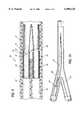
- FIG. 1is an exploded perspective view of the deployment apparatus of the present invention.
- FIG. 2is a perspective view of the structurally supported bifurcated vascular graft of the present invention with structural stent supports located on the interior of the graft shown in phantom. Portions of the hollow tubular limb members of the bifurcated vascular graft are also shown in phantom.
- FIG. 3is a right end view of the structurally supported bifurcated vascular graft of the present invention which is taken from the proximal end of the bifurcated vascular graft which includes the main tubular body of the graft.
- FIG. 4is a cross-sectional view taken along line 4--4 of FIG. 3.
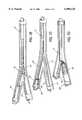
- FIG. 5is a partial cross-sectional view of the deployment apparatus of the present invention with the structurally supported bifurcated vascular graft of the present invention shown loaded within the deployment apparatus of the present invention prior to deployment of the structurally supported bifurcated vascular graft.
- FIG. 6Ais a perspective view of a second hollow limb tube of the deployment apparatus of the present invention which holds the second hollow tubular limb member of the bifurcated vascular graft of the present invention during positioning, and prior to deployment, of the bifurcated vascular graft of the present invention.
- FIG. 6Bis a partial perspective view of a bifurcated blood vessel with the blood vessel shown cut away to illustrate the placement and positioning of the deployment apparatus of the present invention which contains the structurally supported bifurcated vascular graft of the present invention. Portions of the outermost tube of the deployment apparatus are also shown cut away to illustrate the position of the first and second limb tubes and graft body tube which comprise the deployment apparatus. A portion of the second limb tube is shown in phantom.
- FIGS. 7A-7Fare diagrams showing the method and apparatus of the present invention used for deploying the structurally supported bifurcated vascular graft of the present invention.
- FIG. 7Gis a partial perspective view of a bifurcated blood vessel shown cut away to illustrate the structurally supported bifurcated vascular graft of the present invention deployed and anchored in place within the bifurcated blood vessel.
- the deployment apparatus 20includes a graft body tube 21 of variable length and diameter having a tapered tip 22, a first limb tube 23 of variable length and diameter which connects to a hemostatic valve 24, a second limb tube 25 of variable length and diameter having a tapered tip 26 and a guide wire 27 coming from the tapered tip, an outermost tube 28 of variable length and diameter which is large enough to contain the graft body tube 21 and the first and second limb tubes 23 and 25 at the same time and a homeostatic valve 31 connected to the outermost tube 28, and a small metal guide tube 29 of variable length and diameter which is large enough to allow a guide wire to pass therethrough.
- the metal guide tube 29is attached to the graft body tube 21 within the graft body tube 21 near its tapered end 22 when the device is fully loaded and ready to deploy.
- a luer lock 12is shown connected to the metal guide wire 29 and a three-way stopcock for adding and removing fluid is shown connected to the hemostatic valve 24 for the first limb tube 23.
- the deployment apparatus 20 of the present inventionmay be used to deploy any one-piece bifurcated graft, not just the bifurcated vascular graft 30 of the present invention.
- FIG. 2shows a perspective view of the bifurcated vascular graft 30 of the present invention.
- the bifurcated vascular graft 30comprises a hollow tubular body member 32, a first hollow tubular limb member 34, and a second hollow tubular limb member 36.
- the hollow tubular body member 32has a first open end 38 and a second open end 40.
- a first stent 42is positioned about the interior of the hollow tubular body member 32 to support the hollow tubular graft body member 32.
- the first stent 42or any other suitable biocompatible structural support, preferably encompasses the entire interior surface area of the hollow tubular body member 32 in order to provide the necessary structural support.
- the hollow tubular body member 32may be completely supported by attaching several stents along the entire length of the hollow tubular body member 32.
- the first and second hollow tubular limb members 34 and 36have approximately equal diameters, each of which is less than the diameter of the hollow tubular body member 32.
- the first hollow tubular limb member 34comprises a first open end (not shown) and a second open end 44.
- the second hollow tubular limb member 36comprises a first open end (not shown) and a second open end 46.
- Second and third stents 48 and 50are positioned adjacent the second ends 44 and 46 of the first and second hollow limb members 34 and 36 such that they each cover an exterior portion of their respective limb members 34 and 36.
- the second and third stents 48 and 50only encompass that portion of their respective limb members 34 and 36 which extend from the second end 40 of the hollow tubular body member 32.
- the second and third stents 48 and 50may encompass the entire first and second hollow tubular limb members 34 and 36 by extending along their entire lengths. Further, as previously explained with reference to the first stent 42, the second and third stents 48 and 50 may each comprise a plurality of stents or structural supports. Also, these stents may support the first and second hollow tubular limb members 34 and 36 either externally or internally.
- the first and second hollow tubular limb members 34 and 36are circumferentially contained within the hollow tubular body member 32 such that a portion of the hollow tubular limb members 34 and 36 transverse the length of the hollow tubular body member 32.
- the support structures used to provide external structural support to those portions of the hollow tubular limbs 34 and 36 which extend beyond the second end 40 of the hollow tubular body member 32may comprise one or more self expanding stents of varying lengths or any other suitable biocompatible structural support that will self expand to a surrounding vessel diameter.
- the second and third stents 48 and 50are joined and anchored to the first stent 42 to form joints 49 and 51. This configuration prevents twisting and/or misalignment of the limbs 34 and 36 of the graft 30.
- the first hollow tubular limb member 34is loaded into the first limb tube 23
- the second hollow tubular limb member 36is loaded into the second limb tube 25
- the hollow tubular body member 32is loaded into the graft body tube 21.
- the loaded first and second limb tubes 23 and 25may be dimensioned such that they will lie end to end with the loaded graft body tube 21.
- the loaded first and second limb tubes 23 and 25may be of a small enough diameter such that they can be inserted into the interior of the graft body tube 21 so that they can contain the entire length of the respective first and second hollow tubular limb members 34 and 36 within the graft body tube 21.
- the loaded graft body tube 21 and the loaded first and second limb tubes 23 and 25are then all loaded into the outermost tube 28 which is connected to a homeostatic valve 31.
- the metal tube 29 containing a guide wire (not shown), separate and distinct from the guide wire 26 connected to the second limb tube 25,can be inserted through the entire loaded apparatus.
- FIG. 3a right end view of the structurally supported bifurcated vascular graft 30 of the present invention is shown with the right end view taken from the proximal end of the bifurcated vascular graft.
- the first and second hollow tubular limb members 34 and 36are connected to one another along a diameter of the hollow tubular body member 32 which divides the lumen of the hollow tubular body member 32 in half.
- the first and second hollow tubular limb members 34 and 36include first and second lumens 52 and 54, respectively, which are approximately equal to one another area and which fit inside of the lumen of the hollow tubular body member 32.
- the first open ends 56 and 58 of the hollow tubular limb members 34 and 36, respectively,can be seen from this right end view of the bifurcated vascular graft 30. Those portions of the circumference of the first open ends 56 and 58 of the first and second hollow tubular limbs 34 and 36 which are not attached to one another are connected to the circumference of the first open end 38 of the of the hollow tubular body member 32.
- the first stent 42is located about the interior surface area of the hollow tubular body member 32 and is thereby contained between the interior of the hollow tubular body member 32 and the exteriors of the first and second hollow tubular limbs 34 and 36.
- That portion of the circumference of the first ends 56 and 58 of the first and second hollow tubular limbs 34 and 36 which are attached to one anothermay be supported by a cross support stitch or support suture 60 which is positioned underneath the attached area and within the interior of the hollow tubular body member 32.
- Another stitch or suture 57is placed across the diameter of the second end 40 of the hollow tubular body member 32 such that the ends 59 and 61 of the suture are left to trail from the second end 40 of the body member 32 in order to aid in the deployment of the bifurcated vascular graft 30.
- FIG. 3A cross-sectional view of the bifurcated vascular graft 30 of the present invention taken along line 4--4 of FIG. 2 is shown in FIG. 3.
- the first ends 56 and 58 of the first and second hollow tubular limbs 34 and 36are attached to the first end 38 of the hollow tubular body member 32 such that the first and second hollow tubular limbs 34 and 36 are partially contained within the lumen of the hollow tubular body member 32.
- the first stent 42(or structural support) is positioned about the interior surface of the lumen of the hollow tubular body member 32 and is thereby contained between the interior surface of the hollow tubular body member 32 and the exterior surfaces 62 and 64 of the first and second hollow tubular limb members 34 and 36, respectively.
- the second and third stents 48 and 50are positioned adjacent the second ends 44 and 46 of the first and second hollow tubular limb members 34 and 36, respectively, such that they encompass a portion of the exterior surfaces 62 and 64 of the first and second hollow tubular limb members 34 and 36, respectively. Also, as previously described, the first and second hollow tubular limb members 34 and 36 may be structurally supported with stents along their entire length.
- FIG. 5shows a partial cross-section of the deployment apparatus 20 of the present invention with the bifurcated vascular graft 30 of the present invention loaded within the deployment apparatus 20 prior to deployment of the graft 30.
- the first hollow tubular limb member 34 of the bifurcated vascular graft 30is shown loaded into the first limb tube 23 and the second hollow tubular limb member 36 of the bifurcated vascular graft 30 is shown loaded into the second limb tube 25.
- the hollow tubular body member 32 of the bifurcated vascular graft 30is shown loaded into the graft body tube 21 which is tapered at its second end 70 in order to allow for easier movement through the blood vessels and easier re-entry of the graft body tube 21 into the outermost tube 28.
- the loaded first and second limb tubes 23 and 25 and the loaded graft body tube 21are all loaded within the outermost tube 28.
- the first ends 72 and 74 of the loaded first and second limb tubes 23 and 25may lie adjacent the second end 70 of the loaded graft body tube 21 if the second end 70 of the graft body tube 21 is not tapered. However, if the second end 70 of the graft body tube 21 is tapered as shown in FIG. 5, the first ends 72 and 74 of the loaded first and second limb tubes 23 and 25 will not lie in adjacent vertical alignment with the second end 70 of the graft body tube 21. Nevertheless, this configuration of the tubes contained in the deployment apparatus 20 will not affect the successful deployment of a one-piece bifurcated graft from the deployment apparatus 20.
- the first and second limb tubes 23 and 25may also be dimensioned such that they can both be inserted within the interior of the graft body tube 21 at the same time.
- FIG. 6AA perspective view of the second hollow limb tube 25 of the deployment apparatus 20 of the present invention is shown in FIG. 6A.
- the second hollow tube 25includes a tapered tip 26, which may be removable, and a guide wire 27 that is attached to the tapered tip 26.
- the second hollow tubular limb member 34 of the bifurcated vascular graft 30is loaded into the first end 74 of the second hollow limb tube 25 prior to inserting the deployment apparatus into a patient's body and implanting the graft 30.
- FIG. 6Bshows a partial view of a bifurcated blood vessel 80 shown cut away to illustrate the placement and positioning of the deployment apparatus 20 of the present invention. Portions of the outermost tube 28 of the deployment apparatus 20 are also shown cut away to illustrate the positions of the various other tubes which comprise the deployment apparatus 20.
- the first limb tube 23contains the first hollow tubular limb member 34 of the bifurcated vascular graft 30, or any other one-piece bifurcated graft
- the second limb tube 25contains the second hollow tubular limb member 36 of the bifurcated vascular graft 30, or any other one-piece bifurcated graft.
- the first and second limb tubes 23 and 25lie parallel to one another and adjacent to the graft body tube 21 which contains the graft body member 32 of the bifurcated vascular graft 30, or any other one-piece bifurcated graft.
- the first and second limb tubes 23 and 25 and the graft body tube 21are all contained within the outermost tube 28 of the deployment apparatus 20.
- the outermost tube 28has been pulled away from the bifurcation of the blood vessel thereby exposing almost the entire graft body tube 21.
- the guide wire 27 which is attached to the second limb tube 25is passed to the left side 82 of the bifurcated blood vessel 80.
- FIG. 7Ashows the deployment apparatus 20 of the present invention in the same position within the blood vessel 80 as that shown in FIG. 6B with the exception that a longer portion of the blood vessel 80 is shown to illustrate the position of the entire graft body tube 21 within the non-bifurcated portion of a bifurcated blood vessel such as the aorta.
- Techniques commonly known in the prior artare used to place the deployment apparatus 20 and the guide wire 27 at the position shown in FIG. 7A. First, access of both iliac (or femoral) arteries is obtained and sheaths with homeostatic valves are inserted into the left and right common femoral (or left and right common iliac) arteries.
- a separate guide wireis then passed proximally into the aorta from the right sheath.
- an additional guide wireis brought from the left iliac (or femoral) sheath to the right iliac (or femoral) sheath.
- an angiographic catheteris passed from left to right over the guide wire.
- the wireis then removed, leaving the angiographic sheath protruding from the right sheath.
- the right sheathis then removed leaving the angiographic catheter and the aortic guide wire protruding from the artery through the patient's skin.
- Digital pressureis applied for homeostasis.
- the guide wire 27 contained in the delivery apparatus 20is inserted into the angiographic catheter and passed to the sheath in the left side and withdrawn until at least 2/3 to 3/4 of the wire 27 is on the left side.
- the deployment apparatus 20is then loaded onto the second aortic guide wire on the right side.
- the deployment apparatus 20is passed cephalad on the aortic wire (not shown) within the aorta while the second wire 27 on the left is withdrawn further to remove the slack which will occur as the deployment apparatus 20 moves in a cephalad or proximal manner as shown.
- Reverse positioning of the guide wires, catheters and sheathsare carried out when opposite side deployment is carried out, i.e. when the deployment apparatus 30 is inserted into the opposite bifurcated blood vessel.
- Positioning of the deployment apparatus 20 by further movement of the apparatus 20 in a proximal and distal fashion with further gentle traction of the guide wire 27will move the second limb tube 25 through the bifurcation and into the left iliac artery 82 as shown in FIGS. 7B through 7C.
- the deployment apparatus 20Satisfactory positioning of the deployment apparatus 20 is obtained using fluoroscopic visualization such that the graft body tube 21 is located near the bifurcation and below the renal arteries with the first and second limb tubes 23 and 25 extending into the right and left iliac arteries 84 and 82.
- the first and second hollow tubular limb members 34 and 36 of the bifurcated vascular graft 30are deployed by pulling the first and second limb tubes 23 and 25 distally (or caudad) as shown in FIGS. 7D and 7C.
- This processwill uncover the first and second hollow tubular limb members 34 and 36 which have been loaded into the first and second limb tubes 23 and 25 by compressing the second and third stents 48 and 50 which surround the first and second hollow tubular limb members 34 and 36, respectively.
- the self expanding second and third stents 48 and 50will then expand to the surrounding vessel diameter of the right and left iliac arteries 84 and 82.
- the first limb tube 23, which is longer than the second limb tube 25,is retracted back over the metal tube 29 while the second limb tube 25 is pulled through the sheath which still remains on the left side as previously described above with reference to the "cross over" technique.
- the ends 59 and 61 of the suture 57 which is sewn to the second end 40 of the hollow tubular body member 32 of the bifurcated vascular graft 30are held firmly for counter traction while the metal tube 29 attached to the tapered tip 21 of the graft body tube 21 is pushed in a cephalad direction to expose and deploy the hollow tubular body member 32 of the bifurcated vascular graft 30.
- the compressed first stent 42is thereby released and self expands to the diameter of the aorta.
- the bifurcated vascular graft 30 of the present inventionis now fully deployed.
- the first limb tube 23is then pushed cephalad into the graft body tube 21 for a variable distance until a tapered bulb having the same diameter of the graft body tube 21 enters the caudad end of the graft body tube 21 to form a smooth tapered end to the graft body tube 21 so that it will retract easily through the limb members 34 and 36 of the bifurcated vascular graft 30.
- the bifurcated vascular graft of the present inventionmay be comprised of any fabric or plastic materials while the stents or support structures contained in the graft may be comprised of any suitable biocompatible material capable of strengthening the graft.
- the deployment apparatusmay be comprised of any suitable biocompatible material including plastics.
Landscapes
- Health & Medical Sciences (AREA)
- Engineering & Computer Science (AREA)
- Biomedical Technology (AREA)
- Cardiology (AREA)
- Oral & Maxillofacial Surgery (AREA)
- Transplantation (AREA)
- Heart & Thoracic Surgery (AREA)
- Vascular Medicine (AREA)
- Life Sciences & Earth Sciences (AREA)
- Animal Behavior & Ethology (AREA)
- General Health & Medical Sciences (AREA)
- Public Health (AREA)
- Veterinary Medicine (AREA)
- Gastroenterology & Hepatology (AREA)
- Pulmonology (AREA)
- Prostheses (AREA)
- Graft Or Block Polymers (AREA)
Abstract
Description
Claims (26)
Priority Applications (15)
| Application Number | Priority Date | Filing Date | Title |
|---|---|---|---|
| US08/802,478US6090128A (en) | 1997-02-20 | 1997-02-20 | Bifurcated vascular graft deployment device |
| AT98906274TATE418298T1 (en) | 1997-02-20 | 1998-02-06 | BRANCH VESSEL TRANSPLANT AND METHOD AND DEVICE FOR DEPLOYMENT THEREOF |
| PCT/US1998/002534WO1998036708A1 (en) | 1997-02-20 | 1998-02-06 | Bifurcated vascular graft and method and apparatus for deploying same |
| EP98906274AEP1009325B1 (en) | 1997-02-20 | 1998-02-06 | Bifurcated vascular graft and method and apparatus for deploying same |
| KR1019997007607AKR20000075548A (en) | 1997-02-20 | 1998-02-06 | Bifurcated Vascular Graft and Method and Apparatus for Deploying Same |
| CN98802695ACN1248157A (en) | 1997-02-20 | 1998-02-06 | Bifurcated vascular graft and method and apparatus for deploying same |
| AU61540/98AAU725117B2 (en) | 1997-02-20 | 1998-02-06 | Bifurcated vascular graft deployment device |
| DE69840384TDE69840384D1 (en) | 1997-02-20 | 1998-02-06 | Branching vascular graft and method and apparatus for its development |
| JP53670498AJP4555405B2 (en) | 1997-02-20 | 1998-02-06 | Bifurcated artificial blood vessel placement device |
| CA002282343ACA2282343A1 (en) | 1997-02-20 | 1998-02-06 | Bifurcated vascular graft and method and apparatus for deploying same |
| US09/086,247US6156063A (en) | 1997-02-20 | 1998-05-28 | Method of deploying bifurcated vascular graft |
| US09/505,038US6210422B1 (en) | 1997-02-20 | 2000-02-16 | Bifurcated vascular graft deployment device |
| US09/783,720US20020019664A1 (en) | 1997-02-20 | 2001-02-14 | Bifurcated vascular graft and method and apparatus for deploying same |
| US10/639,255US6951572B1 (en) | 1997-02-20 | 2003-08-12 | Bifurcated vascular graft and method and apparatus for deploying same |
| US11/214,427US20050288772A1 (en) | 1997-02-20 | 2005-08-29 | Bifurcated vascular graft and method and apparatus for deploying same |
Applications Claiming Priority (1)
| Application Number | Priority Date | Filing Date | Title |
|---|---|---|---|
| US08/802,478US6090128A (en) | 1997-02-20 | 1997-02-20 | Bifurcated vascular graft deployment device |
Related Child Applications (2)
| Application Number | Title | Priority Date | Filing Date |
|---|---|---|---|
| US09/086,247DivisionUS6156063A (en) | 1997-02-20 | 1998-05-28 | Method of deploying bifurcated vascular graft |
| US09/505,038ContinuationUS6210422B1 (en) | 1997-02-20 | 2000-02-16 | Bifurcated vascular graft deployment device |
Publications (1)
| Publication Number | Publication Date |
|---|---|
| US6090128Atrue US6090128A (en) | 2000-07-18 |
Family
ID=25183805
Family Applications (4)
| Application Number | Title | Priority Date | Filing Date |
|---|---|---|---|
| US08/802,478Expired - LifetimeUS6090128A (en) | 1997-02-20 | 1997-02-20 | Bifurcated vascular graft deployment device |
| US09/086,247Expired - LifetimeUS6156063A (en) | 1997-02-20 | 1998-05-28 | Method of deploying bifurcated vascular graft |
| US09/505,038Expired - LifetimeUS6210422B1 (en) | 1997-02-20 | 2000-02-16 | Bifurcated vascular graft deployment device |
| US09/783,720AbandonedUS20020019664A1 (en) | 1997-02-20 | 2001-02-14 | Bifurcated vascular graft and method and apparatus for deploying same |
Family Applications After (3)
| Application Number | Title | Priority Date | Filing Date |
|---|---|---|---|
| US09/086,247Expired - LifetimeUS6156063A (en) | 1997-02-20 | 1998-05-28 | Method of deploying bifurcated vascular graft |
| US09/505,038Expired - LifetimeUS6210422B1 (en) | 1997-02-20 | 2000-02-16 | Bifurcated vascular graft deployment device |
| US09/783,720AbandonedUS20020019664A1 (en) | 1997-02-20 | 2001-02-14 | Bifurcated vascular graft and method and apparatus for deploying same |
Country Status (10)
| Country | Link |
|---|---|
| US (4) | US6090128A (en) |
| EP (1) | EP1009325B1 (en) |
| JP (1) | JP4555405B2 (en) |
| KR (1) | KR20000075548A (en) |
| CN (1) | CN1248157A (en) |
| AT (1) | ATE418298T1 (en) |
| AU (1) | AU725117B2 (en) |
| CA (1) | CA2282343A1 (en) |
| DE (1) | DE69840384D1 (en) |
| WO (1) | WO1998036708A1 (en) |
Cited By (91)
| Publication number | Priority date | Publication date | Assignee | Title |
|---|---|---|---|---|
| US6290731B1 (en)* | 1998-03-30 | 2001-09-18 | Cordis Corporation | Aortic graft having a precursor gasket for repairing an abdominal aortic aneurysm |
| US20010041928A1 (en)* | 2000-05-04 | 2001-11-15 | Oregon Health Services University | Endovascular stent graft |
| US6478813B1 (en) | 1997-08-01 | 2002-11-12 | Peter T. Keith | Method for joining grafts in a common body passageway |
| US6575994B1 (en) | 1994-02-10 | 2003-06-10 | Teramed, Inc. | Method and apparatus concerning bypass grafts |
| US6626938B1 (en) | 2000-11-16 | 2003-09-30 | Cordis Corporation | Stent graft having a pleated graft member |
| US6663665B2 (en) | 1999-03-11 | 2003-12-16 | Endologix, Inc. | Single puncture bifurcation graft deployment system |
| US6730119B1 (en)* | 2000-10-06 | 2004-05-04 | Board Of Regents Of The University Of Texas System | Percutaneous implantation of partially covered stents in aneurysmally dilated arterial segments with subsequent embolization and obliteration of the aneurysm cavity |
| US20040098084A1 (en)* | 2002-09-02 | 2004-05-20 | Cook Incorporated | Branch grafting device and method |
| US20040133268A1 (en)* | 1998-01-14 | 2004-07-08 | Advanced Stent Technologies, Inc. | Extendible stent apparatus |
| US6835203B1 (en) | 1996-11-04 | 2004-12-28 | Advanced Stent Technologies, Inc. | Extendible stent apparatus |
| US6843802B1 (en) | 2000-11-16 | 2005-01-18 | Cordis Corporation | Delivery apparatus for a self expanding retractable stent |
| US20050033416A1 (en)* | 2003-05-02 | 2005-02-10 | Jacques Seguin | Vascular graft and deployment system |
| US6884258B2 (en) | 1999-06-04 | 2005-04-26 | Advanced Stent Technologies, Inc. | Bifurcation lesion stent delivery using multiple guidewires |
| US6887268B2 (en) | 1998-03-30 | 2005-05-03 | Cordis Corporation | Extension prosthesis for an arterial repair |
| US20050143804A1 (en)* | 2001-10-17 | 2005-06-30 | Haverkost Patrick A. | Method and system for fixation of endoluminal devices |
| WO2004047885A3 (en)* | 2002-11-26 | 2005-07-14 | Endologix Inc | Graft deployment system |
| US20050154444A1 (en)* | 2003-10-10 | 2005-07-14 | Arshad Quadri | System and method for endoluminal grafting of bifurcated and branched vessels |
| US6942692B2 (en) | 2000-11-16 | 2005-09-13 | Cordis Corporation | Supra-renal prosthesis and renal artery bypass |
| US6942672B2 (en) | 2001-10-23 | 2005-09-13 | Vascor, Inc. | Method and apparatus for attaching a conduit to the heart or a blood vessel |
| US6953475B2 (en) | 1998-12-11 | 2005-10-11 | Endologix, Inc. | Bifurcation graft deployment catheter |
| US20050228480A1 (en)* | 2004-04-08 | 2005-10-13 | Douglas Myles S | Endolumenal vascular prosthesis with neointima inhibiting polymeric sleeve |
| US6962602B2 (en) | 1996-11-04 | 2005-11-08 | Advanced Stent Tech Llc | Method for employing an extendible stent apparatus |
| US7066951B2 (en) | 2000-02-02 | 2006-06-27 | Trivascular, Inc. | Delivery system and method for expandable intracorporeal device |
| US20060161244A1 (en)* | 2003-05-02 | 2006-07-20 | Jacques Seguin | Vascular graft and deployment system |
| US7081129B2 (en) | 1998-02-09 | 2006-07-25 | Boston Scientific Santa Rosa Corp. | Endovascular graft |
| US20060271163A1 (en)* | 1998-03-04 | 2006-11-30 | Shokoohi Mehrdad M | Endoluminal vascular prosthesis |
| US7147661B2 (en) | 2001-12-20 | 2006-12-12 | Boston Scientific Santa Rosa Corp. | Radially expandable stent |
| US7147660B2 (en) | 2001-12-20 | 2006-12-12 | Boston Scientific Santa Rosa Corp. | Advanced endovascular graft |
| US7220275B2 (en) | 1996-11-04 | 2007-05-22 | Advanced Stent Technologies, Inc. | Stent with protruding branch portion for bifurcated vessels |
| US7229472B2 (en) | 2000-11-16 | 2007-06-12 | Cordis Corporation | Thoracic aneurysm repair prosthesis and system |
| US7267685B2 (en) | 2000-11-16 | 2007-09-11 | Cordis Corporation | Bilateral extension prosthesis and method of delivery |
| US7314483B2 (en) | 2000-11-16 | 2008-01-01 | Cordis Corp. | Stent graft with branch leg |
| US7326237B2 (en) | 2002-01-08 | 2008-02-05 | Cordis Corporation | Supra-renal anchoring prosthesis |
| AU2003273274B2 (en)* | 2002-09-02 | 2008-02-28 | Cook Incorporated | Branch grafting device and method |
| US7341598B2 (en) | 1999-01-13 | 2008-03-11 | Boston Scientific Scimed, Inc. | Stent with protruding branch portion for bifurcated vessels |
| US7344557B2 (en) | 2003-11-12 | 2008-03-18 | Advanced Stent Technologies, Inc. | Catheter balloon systems and methods |
| US20090093874A1 (en)* | 2002-10-29 | 2009-04-09 | Microfabrica Inc. | Medical Devices and EFAB Methods and Apparatus for Producing Them |
| US20090099648A1 (en)* | 2006-11-09 | 2009-04-16 | Chun Ho Yu | Modular stent graft and delivery system |
| US7585317B2 (en) | 1999-09-23 | 2009-09-08 | Boston Scientific Scimed, Inc. | Stent range transducers |
| US7591846B2 (en) | 1996-11-04 | 2009-09-22 | Boston Scientific Scimed, Inc. | Methods for deploying stents in bifurcations |
| US7655030B2 (en) | 2003-07-18 | 2010-02-02 | Boston Scientific Scimed, Inc. | Catheter balloon systems and methods |
| US7766955B2 (en) | 1996-11-04 | 2010-08-03 | Boston Scientific Scimed, Inc. | Extendible stent apparatus |
| US20100198333A1 (en)* | 2009-01-31 | 2010-08-05 | Macatangay Edwin E | Preform for and an endoluminal prosthesis |
| US7771462B1 (en) | 1999-06-04 | 2010-08-10 | Boston Scientific Scimed, Inc. | Catheter with side sheath and methods |
| US7803178B2 (en) | 2004-01-30 | 2010-09-28 | Trivascular, Inc. | Inflatable porous implants and methods for drug delivery |
| US7935141B2 (en) | 2005-08-17 | 2011-05-03 | C. R. Bard, Inc. | Variable speed stent delivery system |
| US20110130820A1 (en)* | 2009-12-01 | 2011-06-02 | Altura Medical, Inc. | Modular endograft devices and associated systems and methods |
| US8034100B2 (en) | 1999-03-11 | 2011-10-11 | Endologix, Inc. | Graft deployment system |
| US8062344B2 (en) | 2001-04-30 | 2011-11-22 | Angiomed Gmbh & Co. Medizintechnik Kg | Variable speed self-expanding stent delivery system and luer locking connector |
| US8066755B2 (en) | 2007-09-26 | 2011-11-29 | Trivascular, Inc. | System and method of pivoted stent deployment |
| US8083789B2 (en) | 2007-11-16 | 2011-12-27 | Trivascular, Inc. | Securement assembly and method for expandable endovascular device |
| US8118856B2 (en) | 2009-07-27 | 2012-02-21 | Endologix, Inc. | Stent graft |
| US8211167B2 (en) | 1999-12-06 | 2012-07-03 | Boston Scientific Scimed, Inc. | Method of using a catheter with attached flexible side sheath |
| US8216295B2 (en) | 2008-07-01 | 2012-07-10 | Endologix, Inc. | Catheter system and methods of using same |
| US20120179241A1 (en)* | 2007-10-24 | 2012-07-12 | Cordis Corporation | Stent segments axially connected by thin film |
| US8221494B2 (en) | 2008-02-22 | 2012-07-17 | Endologix, Inc. | Apparatus and method of placement of a graft or graft system |
| US8226701B2 (en) | 2007-09-26 | 2012-07-24 | Trivascular, Inc. | Stent and delivery system for deployment thereof |
| US8236040B2 (en) | 2008-04-11 | 2012-08-07 | Endologix, Inc. | Bifurcated graft deployment systems and methods |
| US8241346B2 (en) | 2001-12-20 | 2012-08-14 | Trivascular, Inc. | Endovascular graft and method of delivery |
| US8298280B2 (en) | 2003-08-21 | 2012-10-30 | Boston Scientific Scimed, Inc. | Stent with protruding branch portion for bifurcated vessels |
| US8328861B2 (en) | 2007-11-16 | 2012-12-11 | Trivascular, Inc. | Delivery system and method for bifurcated graft |
| US8377108B2 (en) | 2008-06-02 | 2013-02-19 | Boston Scientific Scimed, Inc. | Staggered two balloon bifurcation catheter assembly and methods |
| US8486134B2 (en) | 2007-08-01 | 2013-07-16 | Boston Scientific Scimed, Inc. | Bifurcation treatment system and methods |
| US8491646B2 (en) | 2009-07-15 | 2013-07-23 | Endologix, Inc. | Stent graft |
| US8500789B2 (en) | 2007-07-11 | 2013-08-06 | C. R. Bard, Inc. | Device for catheter sheath retraction |
| US8523931B2 (en) | 2007-01-12 | 2013-09-03 | Endologix, Inc. | Dual concentric guidewire and methods of bifurcated graft deployment |
| US8617231B2 (en) | 2001-05-18 | 2013-12-31 | Boston Scientific Scimed, Inc. | Dual guidewire exchange catheter system |
| US8663309B2 (en) | 2007-09-26 | 2014-03-04 | Trivascular, Inc. | Asymmetric stent apparatus and method |
| US8747456B2 (en) | 2007-12-31 | 2014-06-10 | Boston Scientific Scimed, Inc. | Bifurcation stent delivery system and methods |
| US8808350B2 (en) | 2011-03-01 | 2014-08-19 | Endologix, Inc. | Catheter system and methods of using same |
| US8808346B2 (en) | 2006-01-13 | 2014-08-19 | C. R. Bard, Inc. | Stent delivery system |
| US8821561B2 (en) | 2006-02-22 | 2014-09-02 | Boston Scientific Scimed, Inc. | Marker arrangement for bifurcation catheter |
| US8827954B2 (en) | 2008-06-05 | 2014-09-09 | Boston Scientific Scimed, Inc. | Deflatable bifurcated device |
| US8858613B2 (en) | 2010-09-20 | 2014-10-14 | Altura Medical, Inc. | Stent graft delivery systems and associated methods |
| US8936567B2 (en) | 2007-11-14 | 2015-01-20 | Boston Scientific Scimed, Inc. | Balloon bifurcated lumen treatment |
| US8945202B2 (en) | 2009-04-28 | 2015-02-03 | Endologix, Inc. | Fenestrated prosthesis |
| US8992595B2 (en) | 2012-04-04 | 2015-03-31 | Trivascular, Inc. | Durable stent graft with tapered struts and stable delivery methods and devices |
| US9078779B2 (en) | 2006-08-07 | 2015-07-14 | C. R. Bard, Inc. | Hand-held actuator device |
| US9393100B2 (en) | 2010-11-17 | 2016-07-19 | Endologix, Inc. | Devices and methods to treat vascular dissections |
| US9498363B2 (en) | 2012-04-06 | 2016-11-22 | Trivascular, Inc. | Delivery catheter for endovascular device |
| US9579103B2 (en) | 2009-05-01 | 2017-02-28 | Endologix, Inc. | Percutaneous method and device to treat dissections |
| US9737426B2 (en) | 2013-03-15 | 2017-08-22 | Altura Medical, Inc. | Endograft device delivery systems and associated methods |
| US9801745B2 (en) | 2010-10-21 | 2017-10-31 | C.R. Bard, Inc. | System to deliver a bodily implant |
| US9925031B2 (en) | 2009-12-28 | 2018-03-27 | Cook Medical Technologies Llc | Endoluminal device with kink-resistant regions |
| US10159557B2 (en) | 2007-10-04 | 2018-12-25 | Trivascular, Inc. | Modular vascular graft for low profile percutaneous delivery |
| US10271974B2 (en) | 2011-06-24 | 2019-04-30 | Cook Medical Technologies Llc | Helical stent |
| US10285833B2 (en) | 2012-08-10 | 2019-05-14 | Lombard Medical Limited | Stent delivery systems and associated methods |
| US10772717B2 (en) | 2009-05-01 | 2020-09-15 | Endologix, Inc. | Percutaneous method and device to treat dissections |
| US11026822B2 (en) | 2006-01-13 | 2021-06-08 | C. R. Bard, Inc. | Stent delivery system |
| US11129737B2 (en) | 2015-06-30 | 2021-09-28 | Endologix Llc | Locking assembly for coupling guidewire to delivery system |
| US11406518B2 (en) | 2010-11-02 | 2022-08-09 | Endologix Llc | Apparatus and method of placement of a graft or graft system |
Families Citing this family (60)
| Publication number | Priority date | Publication date | Assignee | Title |
|---|---|---|---|---|
| US6051020A (en) | 1994-02-09 | 2000-04-18 | Boston Scientific Technology, Inc. | Bifurcated endoluminal prosthesis |
| US5609627A (en)* | 1994-02-09 | 1997-03-11 | Boston Scientific Technology, Inc. | Method for delivering a bifurcated endoluminal prosthesis |
| UA58485C2 (en) | 1996-05-03 | 2003-08-15 | Медінол Лтд. | Method for manufacture of bifurcated stent (variants) and bifurcated stent (variants) |
| US6251133B1 (en) | 1996-05-03 | 2001-06-26 | Medinol Ltd. | Bifurcated stent with improved side branch aperture and method of making same |
| US6770092B2 (en) | 1996-05-03 | 2004-08-03 | Medinol Ltd. | Method of delivering a bifurcated stent |
| US6440165B1 (en) | 1996-05-03 | 2002-08-27 | Medinol, Ltd. | Bifurcated stent with improved side branch aperture and method of making same |
| US7641685B2 (en) | 1996-05-03 | 2010-01-05 | Medinol Ltd. | System and method for delivering a bifurcated stent |
| US6132458A (en)* | 1998-05-15 | 2000-10-17 | American Medical Systems, Inc. | Method and device for loading a stent |
| US6113612A (en)* | 1998-11-06 | 2000-09-05 | St. Jude Medical Cardiovascular Group, Inc. | Medical anastomosis apparatus |
| WO2000027463A1 (en)* | 1998-11-11 | 2000-05-18 | Mark Wilson Ian Webster | Bifurcation stent and delivery systems |
| CA2329213C (en) | 1999-01-22 | 2005-08-09 | Gore Enterprise Holdings, Inc. | Low profile stent and graft combination |
| US6770079B2 (en)* | 1999-03-16 | 2004-08-03 | American Osteomedix, Inc. | Apparatus and method for fixation of osteoporotic bone |
| US6402779B1 (en) | 1999-07-26 | 2002-06-11 | Endomed, Inc. | Balloon-assisted intraluminal stent graft |
| NL1012800C2 (en)* | 1999-08-10 | 2001-02-13 | Rigitec B V | Stent device, especially for blood vessel with Y shaped fork, has spaces between prim. and sec. stents blocked by filler pieces |
| US6183481B1 (en) | 1999-09-22 | 2001-02-06 | Endomed Inc. | Delivery system for self-expanding stents and grafts |
| AU1594301A (en) | 1999-12-02 | 2001-06-12 | Endologix, Inc. | Ptfe embedded low profile endoluminal prosthesis |
| US6451050B1 (en)* | 2000-04-28 | 2002-09-17 | Cardiovasc, Inc. | Stent graft and method |
| EP1745761A1 (en) | 2000-08-23 | 2007-01-24 | LeMaitre Acquisition LLC | Method of manufacturing custom intravascular devices |
| WO2002030329A2 (en) | 2000-10-13 | 2002-04-18 | Rex Medical, L.P. | Covered stents with side branch |
| US20040138734A1 (en)* | 2001-04-11 | 2004-07-15 | Trivascular, Inc. | Delivery system and method for bifurcated graft |
| US6733521B2 (en) | 2001-04-11 | 2004-05-11 | Trivascular, Inc. | Delivery system and method for endovascular graft |
| US6761733B2 (en)* | 2001-04-11 | 2004-07-13 | Trivascular, Inc. | Delivery system and method for bifurcated endovascular graft |
| ES2319621T3 (en) | 2001-08-23 | 2009-05-11 | Darrell C. Gumm | ROTARY SYSTEM OF IMPLANT OF ENDOVASCULAR PROTESIS FOR ACCSO OF SIDE BRANCH AND PROTECTION. |
| US6939368B2 (en) | 2002-01-17 | 2005-09-06 | Scimed Life Systems, Inc. | Delivery system for self expanding stents for use in bifurcated vessels |
| US6989024B2 (en) | 2002-02-28 | 2006-01-24 | Counter Clockwise, Inc. | Guidewire loaded stent for delivery through a catheter |
| US7300460B2 (en)* | 2002-12-31 | 2007-11-27 | Counter Clockwise, Inc. | Bifurcated guidewire and methods of use |
| US7367989B2 (en)* | 2003-02-27 | 2008-05-06 | Scimed Life Systems, Inc. | Rotating balloon expandable sheath bifurcation delivery |
| US7314480B2 (en)* | 2003-02-27 | 2008-01-01 | Boston Scientific Scimed, Inc. | Rotating balloon expandable sheath bifurcation delivery |
| EP1608293B1 (en) | 2003-04-03 | 2015-06-03 | Cook Medical Technologies LLC | Deployment system for a branched stent graft |
| US20040254628A1 (en)* | 2003-06-13 | 2004-12-16 | Patrice Nazzaro | One-branch stent-graft for bifurcated lumens |
| US8784472B2 (en)* | 2003-08-15 | 2014-07-22 | Boston Scientific Scimed, Inc. | Clutch driven stent delivery system |
| US7686841B2 (en)* | 2003-12-29 | 2010-03-30 | Boston Scientific Scimed, Inc. | Rotating balloon expandable sheath bifurcation delivery system |
| US7922753B2 (en)* | 2004-01-13 | 2011-04-12 | Boston Scientific Scimed, Inc. | Bifurcated stent delivery system |
| US8012192B2 (en)* | 2004-02-18 | 2011-09-06 | Boston Scientific Scimed, Inc. | Multi-stent delivery system |
| US7225518B2 (en)* | 2004-02-23 | 2007-06-05 | Boston Scientific Scimed, Inc. | Apparatus for crimping a stent assembly |
| US7744619B2 (en) | 2004-02-24 | 2010-06-29 | Boston Scientific Scimed, Inc. | Rotatable catheter assembly |
| US7922740B2 (en) | 2004-02-24 | 2011-04-12 | Boston Scientific Scimed, Inc. | Rotatable catheter assembly |
| US20050273149A1 (en)* | 2004-06-08 | 2005-12-08 | Tran Thomas T | Bifurcated stent delivery system |
| KR100601969B1 (en)* | 2004-06-15 | 2006-07-14 | 주식회사 에스앤지바이오텍 | Artificial vessel stent |
| US20070050015A1 (en)* | 2005-08-25 | 2007-03-01 | Scimed Life Systems, Inc. | Endoluminal prosthesis adapted to deployment in a distorted branched body lumen and method of deploying the same |
| US20070203563A1 (en)* | 2006-02-13 | 2007-08-30 | Stephen Hebert | System for delivering a stent |
| US20080039926A1 (en)* | 2006-08-11 | 2008-02-14 | Majercak David C | Stent graft sealing zone connecting structure |
| WO2008034140A2 (en)* | 2006-09-15 | 2008-03-20 | Pioneer Surgical Technology, Inc. | Systems and methods for sizing, inserting and securing an implant intervertebral space |
| US8715350B2 (en) | 2006-09-15 | 2014-05-06 | Pioneer Surgical Technology, Inc. | Systems and methods for securing an implant in intervertebral space |
| US20080255654A1 (en)* | 2007-03-22 | 2008-10-16 | Bay Street Medical | System for delivering a stent |
| US9144508B2 (en)* | 2007-07-19 | 2015-09-29 | Back Bay Medical Inc. | Radially expandable stent |
| US20090287145A1 (en)* | 2008-05-15 | 2009-11-19 | Altura Interventional, Inc. | Devices and methods for treatment of abdominal aortic aneurysms |
| US8333003B2 (en) | 2008-05-19 | 2012-12-18 | Boston Scientific Scimed, Inc. | Bifurcation stent crimping systems and methods |
| CA2727000C (en)* | 2008-06-04 | 2014-01-07 | Gore Enterprise Holdings, Inc. | Controlled deployable medical device and method of making the same |
| US8133199B2 (en) | 2008-08-27 | 2012-03-13 | Boston Scientific Scimed, Inc. | Electroactive polymer activation system for a medical device |
| WO2010064244A2 (en) | 2008-12-04 | 2010-06-10 | Inverthis Ltd | Delivery system for delivering a graft from the middle thereof |
| CN101897629B (en)* | 2009-05-26 | 2013-08-07 | 上海微创医疗器械(集团)有限公司 | Branched membrane-covered support conveying system and conveying method thereof |
| US9154866B2 (en) | 2009-06-10 | 2015-10-06 | Apple Inc. | Fiber-based electronic device structures |
| JP5539454B2 (en)* | 2012-07-20 | 2014-07-02 | ファナック株式会社 | Striated structure for industrial robot with hollow member |
| US20200281711A1 (en)* | 2017-02-01 | 2020-09-10 | Endologix, Inc. | Longitudinally extendable stent graft systems and methods |
| WO2019051260A1 (en) | 2017-09-08 | 2019-03-14 | Pioneer Surgical Technology, Inc. | Intervertebral implants, instruments, and methods |
| USD907771S1 (en) | 2017-10-09 | 2021-01-12 | Pioneer Surgical Technology, Inc. | Intervertebral implant |
| DE102018111614A1 (en)* | 2018-05-15 | 2019-11-21 | Jörg Teßarek | Multi-lumen implant |
| WO2020181430A1 (en)* | 2019-03-08 | 2020-09-17 | 孟国伟 | Artificial blood vessel |
| KR102561897B1 (en)* | 2021-01-27 | 2023-08-01 | 주식회사 에스앤지바이오텍 | Stent and manufacturing method thereof |
Citations (86)
| Publication number | Priority date | Publication date | Assignee | Title |
|---|---|---|---|---|
| US2127903A (en)* | 1936-05-05 | 1938-08-23 | Davis & Geck Inc | Tube for surgical purposes and method of preparing and using the same |
| US2845959A (en)* | 1956-03-26 | 1958-08-05 | John B Sidebotham | Bifurcated textile tubes and method of weaving the same |
| US2990605A (en)* | 1957-01-30 | 1961-07-04 | Demsyk Paul | Method of forming artificial vascular members |
| US3029819A (en)* | 1959-07-30 | 1962-04-17 | J L Mcatee | Artery graft and method of producing artery grafts |
| US3096560A (en)* | 1958-11-21 | 1963-07-09 | William J Liebig | Process for synthetic vascular implants |
| US3805301A (en)* | 1972-07-28 | 1974-04-23 | Meadox Medicals Inc | Tubular grafts having indicia thereon |
| US4497074A (en)* | 1976-04-05 | 1985-02-05 | Agence National De Valorisation De La Recherche (Anvar) | Organ prostheses |
| US4501263A (en)* | 1982-03-31 | 1985-02-26 | Harbuck Stanley C | Method for reducing hypertension of a liver |
| US4503568A (en)* | 1981-11-25 | 1985-03-12 | New England Deaconess Hospital | Small diameter vascular bypass and method |
| US4592754A (en)* | 1983-09-09 | 1986-06-03 | Gupte Pradeep M | Surgical prosthetic vessel graft and catheter combination and method |
| US4617932A (en)* | 1984-04-25 | 1986-10-21 | Elliot Kornberg | Device and method for performing an intraluminal abdominal aortic aneurysm repair |
| US4816028A (en)* | 1987-07-01 | 1989-03-28 | Indu Kapadia | Woven vascular graft |
| US4840940A (en)* | 1987-10-21 | 1989-06-20 | Sottiurai Vikrom S | Method for reducing the occurrence of distal anastomotic intimal hyperplasia using fractionated heparin |
| US4856516A (en)* | 1989-01-09 | 1989-08-15 | Cordis Corporation | Endovascular stent apparatus and method |
| US4878906A (en)* | 1986-03-25 | 1989-11-07 | Servetus Partnership | Endoprosthesis for repairing a damaged vessel |
| US4907336A (en)* | 1987-03-13 | 1990-03-13 | Cook Incorporated | Method of making an endovascular stent and delivery system |
| US4922905A (en)* | 1985-11-30 | 1990-05-08 | Strecker Ernst P | Dilatation catheter |
| US5019909A (en)* | 1988-01-30 | 1991-05-28 | Fuji Photo Film Co., Ltd. | Video camera for photographing papers |
| EP0177330B1 (en)* | 1984-10-01 | 1991-06-19 | Cook Incorporated | Percutaneous endovascular stent |
| US5078726A (en)* | 1989-02-01 | 1992-01-07 | Kreamer Jeffry W | Graft stent and method of repairing blood vessels |
| US5104399A (en)* | 1986-12-10 | 1992-04-14 | Endovascular Technologies, Inc. | Artificial graft and implantation method |
| US5108424A (en)* | 1984-01-30 | 1992-04-28 | Meadox Medicals, Inc. | Collagen-impregnated dacron graft |
| US5156619A (en)* | 1990-06-15 | 1992-10-20 | Ehrenfeld William K | Flanged end-to-side vascular graft |
| US5178634A (en)* | 1989-03-31 | 1993-01-12 | Wilson Ramos Martinez | Aortic valved tubes for human implants |
| US5197976A (en)* | 1991-09-16 | 1993-03-30 | Atrium Medical Corporation | Manually separable multi-lumen vascular graft |
| WO1993013825A1 (en)* | 1992-01-15 | 1993-07-22 | Cook Incorporated | Spiral stent |
| US5256141A (en)* | 1992-12-22 | 1993-10-26 | Nelson Gencheff | Biological material deployment method and apparatus |
| US5275622A (en)* | 1983-12-09 | 1994-01-04 | Harrison Medical Technologies, Inc. | Endovascular grafting apparatus, system and method and devices for use therewith |
| US5282824A (en)* | 1990-10-09 | 1994-02-01 | Cook, Incorporated | Percutaneous stent assembly |
| US5304200A (en)* | 1991-05-29 | 1994-04-19 | Cordis Corporation | Welded radially expandable endoprosthesis and the like |
| EP0596145A1 (en)* | 1992-10-31 | 1994-05-11 | Schneider (Europe) Ag | Disposition for implanting a self-expanding endoprothesis |
| US5314472A (en)* | 1991-10-01 | 1994-05-24 | Cook Incorporated | Vascular stent |
| US5316023A (en)* | 1992-01-08 | 1994-05-31 | Expandable Grafts Partnership | Method for bilateral intra-aortic bypass |
| US5342387A (en)* | 1992-06-18 | 1994-08-30 | American Biomed, Inc. | Artificial support for a blood vessel |
| EP0621015A1 (en)* | 1993-04-23 | 1994-10-26 | Schneider (Europe) Ag | Stent with a covering layer of elastic material and methods for applying the layer on the stent |
| US5360443A (en)* | 1990-06-11 | 1994-11-01 | Barone Hector D | Aortic graft for repairing an abdominal aortic aneurysm |
| US5366504A (en)* | 1992-05-20 | 1994-11-22 | Boston Scientific Corporation | Tubular medical prosthesis |
| US5370683A (en)* | 1992-03-25 | 1994-12-06 | Cook Incorporated | Vascular stent |
| US5387235A (en)* | 1991-10-25 | 1995-02-07 | Cook Incorporated | Expandable transluminal graft prosthesis for repair of aneurysm |
| US5423886A (en)* | 1987-05-11 | 1995-06-13 | Sorin Biomedica S.P.A. | Cyclically deformable haemocompatible and biocompatible devices coated with biocompatible carbonaceous material |
| US5425765A (en)* | 1993-06-25 | 1995-06-20 | Tiefenbrun; Jonathan | Surgical bypass method |
| EP0659389A1 (en)* | 1993-10-20 | 1995-06-28 | Schneider (Europe) Ag | Endoprothese |
| US5443498A (en)* | 1991-10-01 | 1995-08-22 | Cook Incorporated | Vascular stent and method of making and implanting a vacsular stent |
| US5443500A (en)* | 1989-01-26 | 1995-08-22 | Advanced Cardiovascular Systems, Inc. | Intravascular stent |
| US5456713A (en)* | 1991-10-25 | 1995-10-10 | Cook Incorporated | Expandable transluminal graft prosthesis for repairs of aneurysm and method for implanting |
| US5489295A (en)* | 1991-04-11 | 1996-02-06 | Endovascular Technologies, Inc. | Endovascular graft having bifurcation and apparatus and method for deploying the same |
| US5496365A (en)* | 1992-07-02 | 1996-03-05 | Sgro; Jean-Claude | Autoexpandable vascular endoprosthesis |
| US5507771A (en)* | 1992-06-15 | 1996-04-16 | Cook Incorporated | Stent assembly |
| US5522881A (en)* | 1994-06-28 | 1996-06-04 | Meadox Medicals, Inc. | Implantable tubular prosthesis having integral cuffs |
| US5522883A (en)* | 1995-02-17 | 1996-06-04 | Meadox Medicals, Inc. | Endoprosthesis stent/graft deployment system |
| US5545211A (en)* | 1993-09-27 | 1996-08-13 | Sooho Medi-Tech Co., Ltd. | Stent for expanding a lumen |
| US5562728A (en)* | 1983-12-09 | 1996-10-08 | Endovascular Tech Inc | Endovascular grafting apparatus, system and method and devices for use therewith |
| EP0740928A2 (en)* | 1995-04-12 | 1996-11-06 | Corvita Europe | Self-expanding stent for introducing a medical device in a body cavity and manufacturing process |
| EP0747020A2 (en)* | 1995-06-07 | 1996-12-11 | Cook Incorporated | Improved barb and expandable transluminal graft prothesis for repair of aneurysm |
| WO1996041589A1 (en)* | 1995-06-13 | 1996-12-27 | William Cook Europe A/S | A device for implantation in a vessel or hollow organ lumen |
| US5591229A (en)* | 1990-06-11 | 1997-01-07 | Parodi; Juan C. | Aortic graft for repairing an abdominal aortic aneurysm |
| US5609627A (en)* | 1994-02-09 | 1997-03-11 | Boston Scientific Technology, Inc. | Method for delivering a bifurcated endoluminal prosthesis |
| WO1997010777A1 (en)* | 1995-09-18 | 1997-03-27 | William Cook Europe A/S | A self-expanding endovascular stent assembly, a method for the manufacture thereof and a stent introducer set comprising such a stent assembly and an introducer catheter for introduction of said stent into a body passage or duct of a patient |
| US5628788A (en)* | 1995-11-07 | 1997-05-13 | Corvita Corporation | Self-expanding endoluminal stent-graft |
| US5632772A (en)* | 1993-10-21 | 1997-05-27 | Corvita Corporation | Expandable supportive branched endoluminal grafts |
| EP0775470A1 (en)* | 1995-11-14 | 1997-05-28 | Schneider (Europe) Ag | Stent delivery device and method for manufacturing a stent delivery device |
| US5643339A (en)* | 1992-08-06 | 1997-07-01 | William Cook Europe A/S | Prosthetic device for sustaining a blood-vessel or hollow organ lumen |
| US5647857A (en)* | 1995-03-16 | 1997-07-15 | Endotex Interventional Systems, Inc. | Protective intraluminal sheath |
| US5653743A (en)* | 1994-09-09 | 1997-08-05 | Martin; Eric C. | Hypogastric artery bifurcation graft and method of implantation |
| US5653727A (en)* | 1987-10-19 | 1997-08-05 | Medtronic, Inc. | Intravascular stent |
| US5653747A (en)* | 1992-12-21 | 1997-08-05 | Corvita Corporation | Luminal graft endoprostheses and manufacture thereof |
| US5653746A (en)* | 1994-03-08 | 1997-08-05 | Meadox Medicals, Inc. | Radially expandable tubular prosthesis |
| US5662702A (en)* | 1995-04-20 | 1997-09-02 | Keranen; Victor J. | Intravascular graft and catheter |
| US5665115A (en)* | 1992-02-21 | 1997-09-09 | Boston Scientific Technology, Inc. | Intraluminal stent |
| US5665117A (en)* | 1995-11-27 | 1997-09-09 | Rhodes; Valentine J. | Endovascular prosthesis with improved sealing means for aneurysmal arterial disease and method of use |
| US5674241A (en)* | 1995-02-22 | 1997-10-07 | Menlo Care, Inc. | Covered expanding mesh stent |
| US5676697A (en)* | 1996-07-29 | 1997-10-14 | Cardiovascular Dynamics, Inc. | Two-piece, bifurcated intraluminal graft for repair of aneurysm |
| US5676696A (en)* | 1995-02-24 | 1997-10-14 | Intervascular, Inc. | Modular bifurcated intraluminal grafts and methods for delivering and assembling same |
| US5679400A (en)* | 1993-04-26 | 1997-10-21 | Medtronic, Inc. | Intravascular stent and method |
| US5681346A (en)* | 1995-03-14 | 1997-10-28 | Advanced Cardiovascular Systems, Inc. | Expandable stent forming projecting barbs and method for deploying |
| US5683451A (en)* | 1994-06-08 | 1997-11-04 | Cardiovascular Concepts, Inc. | Apparatus and methods for deployment release of intraluminal prostheses |
| US5690644A (en)* | 1992-12-30 | 1997-11-25 | Schneider (Usa) Inc. | Apparatus for deploying body implantable stent |
| US5693066A (en)* | 1995-12-21 | 1997-12-02 | Medtronic, Inc. | Stent mounting and transfer device and method |
| US5693084A (en)* | 1991-10-25 | 1997-12-02 | Cook Incorporated | Expandable transluminal graft prosthesis for repair of aneurysm |
| US5693088A (en)* | 1993-11-08 | 1997-12-02 | Lazarus; Harrison M. | Intraluminal vascular graft |
| US5695516A (en)* | 1996-02-21 | 1997-12-09 | Iso Stent, Inc. | Longitudinally elongating balloon expandable stent |
| US5695517A (en)* | 1994-02-10 | 1997-12-09 | Endovascular Systems, Inc. | Method and apparatus for forming an endoluminal bifurcated graft |
| US5723004A (en)* | 1993-10-21 | 1998-03-03 | Corvita Corporation | Expandable supportive endoluminal grafts |
| US5746766A (en)* | 1995-05-09 | 1998-05-05 | Edoga; John K. | Surgical stent |
| US5755771A (en)* | 1994-11-03 | 1998-05-26 | Divysio Solutions Ulc | Expandable stent and method of delivery of same |
| US5769885A (en)* | 1991-04-11 | 1998-06-23 | Endovascular Technologies, Inc. | Bifurcated multicapsule intraluminal grafting system and method |
Family Cites Families (34)
| Publication number | Priority date | Publication date | Assignee | Title |
|---|---|---|---|---|
| US4800882A (en) | 1987-03-13 | 1989-01-31 | Cook Incorporated | Endovascular stent and delivery system |
| US5019090A (en)* | 1988-09-01 | 1991-05-28 | Corvita Corporation | Radially expandable endoprosthesis and the like |
| US4994071A (en) | 1989-05-22 | 1991-02-19 | Cordis Corporation | Bifurcating stent apparatus and method |
| US5064435A (en) | 1990-06-28 | 1991-11-12 | Schneider (Usa) Inc. | Self-expanding prosthesis having stable axial length |
| US5330500A (en) | 1990-10-18 | 1994-07-19 | Song Ho Y | Self-expanding endovascular stent with silicone coating |
| US5135536A (en) | 1991-02-05 | 1992-08-04 | Cordis Corporation | Endovascular stent and method |
| US5282860A (en) | 1991-10-16 | 1994-02-01 | Olympus Optical Co., Ltd. | Stent tube for medical use |
| CA2081424C (en) | 1991-10-25 | 2008-12-30 | Timothy A. Chuter | Expandable transluminal graft prosthesis for repair of aneurysm |
| US5405377A (en) | 1992-02-21 | 1995-04-11 | Endotech Ltd. | Intraluminal stent |
| AU689094B2 (en) | 1993-04-22 | 1998-03-26 | C.R. Bard Inc. | Non-migrating vascular prosthesis and minimally invasive placement system therefor |
| US5843167A (en) | 1993-04-22 | 1998-12-01 | C. R. Bard, Inc. | Method and apparatus for recapture of hooked endoprosthesis |
| CA2125258C (en)* | 1993-08-05 | 1998-12-22 | Dinah B Quiachon | Multicapsule intraluminal grafting system and method |
| US6027779A (en) | 1993-08-18 | 2000-02-22 | W. L. Gore & Associates, Inc. | Thin-wall polytetrafluoroethylene tube |
| US6159565A (en) | 1993-08-18 | 2000-12-12 | W. L. Gore & Associates, Inc. | Thin-wall intraluminal graft |
| ES2135520T3 (en) | 1993-11-04 | 1999-11-01 | Bard Inc C R | NON-MIGRANT VASCULAR PROSTHESIS. |
| US5554181A (en) | 1994-05-04 | 1996-09-10 | Regents Of The University Of Minnesota | Stent |
| US5456694A (en)* | 1994-05-13 | 1995-10-10 | Stentco, Inc. | Device for delivering and deploying intraluminal devices |
| DE4418336A1 (en) | 1994-05-26 | 1995-11-30 | Angiomed Ag | Stent for widening and holding open receptacles |
| EP0790810B1 (en) | 1994-11-09 | 2004-04-28 | Endotex Interventional Systems, Inc. | Kit of delivery catheter and graft for aneurysm repair |
| AU3783195A (en) | 1994-11-15 | 1996-05-23 | Advanced Cardiovascular Systems Inc. | Intraluminal stent for attaching a graft |
| US5755770A (en)* | 1995-01-31 | 1998-05-26 | Boston Scientific Corporatiion | Endovascular aortic graft |
| US5575818A (en) | 1995-02-14 | 1996-11-19 | Corvita Corporation | Endovascular stent with locking ring |
| US5641373A (en) | 1995-04-17 | 1997-06-24 | Baxter International Inc. | Method of manufacturing a radially-enlargeable PTFE tape-reinforced vascular graft |
| AU5918996A (en)* | 1995-05-09 | 1996-11-29 | John K. Edoga | Methods and apparatus for treating abdominal aortic aneurysm s |
| AU5950696A (en) | 1995-06-05 | 1996-12-24 | Creative Products Resource, Inc. | Dry-cleaning kit for in-dryer use |
| US5824037A (en) | 1995-10-03 | 1998-10-20 | Medtronic, Inc. | Modular intraluminal prostheses construction and methods |
| US5593417A (en) | 1995-11-27 | 1997-01-14 | Rhodes; Valentine J. | Intravascular stent with secure mounting means |
| US5810836A (en) | 1996-03-04 | 1998-09-22 | Myocardial Stents, Inc. | Device and method for trans myocardial revascularization (TMR) |
| US5843160A (en)* | 1996-04-01 | 1998-12-01 | Rhodes; Valentine J. | Prostheses for aneurysmal and/or occlusive disease at a bifurcation in a vessel, duct, or lumen |
| US5860998A (en) | 1996-11-25 | 1999-01-19 | C. R. Bard, Inc. | Deployment device for tubular expandable prosthesis |
| JP4042998B2 (en) | 1997-01-29 | 2008-02-06 | クック インコーポレイテッド | Bell bottom modular stent graft |
| US5824053A (en) | 1997-03-18 | 1998-10-20 | Endotex Interventional Systems, Inc. | Helical mesh endoprosthesis and methods of use |
| US6070589A (en) | 1997-08-01 | 2000-06-06 | Teramed, Inc. | Methods for deploying bypass graft stents |
| US5855599A (en) | 1997-09-02 | 1999-01-05 | Sitek, Inc. | Silicon micro machined occlusion implant |
- 1997
- 1997-02-20USUS08/802,478patent/US6090128A/ennot_activeExpired - Lifetime
- 1998
- 1998-02-06JPJP53670498Apatent/JP4555405B2/ennot_activeExpired - Fee Related
- 1998-02-06WOPCT/US1998/002534patent/WO1998036708A1/ennot_activeApplication Discontinuation
- 1998-02-06ATAT98906274Tpatent/ATE418298T1/ennot_activeIP Right Cessation
- 1998-02-06KRKR1019997007607Apatent/KR20000075548A/ennot_activeWithdrawn
- 1998-02-06CNCN98802695Apatent/CN1248157A/enactivePending
- 1998-02-06AUAU61540/98Apatent/AU725117B2/ennot_activeCeased
- 1998-02-06CACA002282343Apatent/CA2282343A1/ennot_activeAbandoned
- 1998-02-06EPEP98906274Apatent/EP1009325B1/ennot_activeExpired - Lifetime
- 1998-02-06DEDE69840384Tpatent/DE69840384D1/ennot_activeExpired - Lifetime
- 1998-05-28USUS09/086,247patent/US6156063A/ennot_activeExpired - Lifetime
- 2000
- 2000-02-16USUS09/505,038patent/US6210422B1/ennot_activeExpired - Lifetime
- 2001
- 2001-02-14USUS09/783,720patent/US20020019664A1/ennot_activeAbandoned
Patent Citations (100)
| Publication number | Priority date | Publication date | Assignee | Title |
|---|---|---|---|---|
| US2127903A (en)* | 1936-05-05 | 1938-08-23 | Davis & Geck Inc | Tube for surgical purposes and method of preparing and using the same |
| US2845959A (en)* | 1956-03-26 | 1958-08-05 | John B Sidebotham | Bifurcated textile tubes and method of weaving the same |
| US2990605A (en)* | 1957-01-30 | 1961-07-04 | Demsyk Paul | Method of forming artificial vascular members |
| US3096560A (en)* | 1958-11-21 | 1963-07-09 | William J Liebig | Process for synthetic vascular implants |
| US3029819A (en)* | 1959-07-30 | 1962-04-17 | J L Mcatee | Artery graft and method of producing artery grafts |
| US3805301A (en)* | 1972-07-28 | 1974-04-23 | Meadox Medicals Inc | Tubular grafts having indicia thereon |
| US4497074A (en)* | 1976-04-05 | 1985-02-05 | Agence National De Valorisation De La Recherche (Anvar) | Organ prostheses |
| US4503568A (en)* | 1981-11-25 | 1985-03-12 | New England Deaconess Hospital | Small diameter vascular bypass and method |
| US4501263A (en)* | 1982-03-31 | 1985-02-26 | Harbuck Stanley C | Method for reducing hypertension of a liver |
| US4592754A (en)* | 1983-09-09 | 1986-06-03 | Gupte Pradeep M | Surgical prosthetic vessel graft and catheter combination and method |
| US5562728A (en)* | 1983-12-09 | 1996-10-08 | Endovascular Tech Inc | Endovascular grafting apparatus, system and method and devices for use therewith |
| US5275622A (en)* | 1983-12-09 | 1994-01-04 | Harrison Medical Technologies, Inc. | Endovascular grafting apparatus, system and method and devices for use therewith |
| US5662700A (en)* | 1983-12-09 | 1997-09-02 | Endovascular Technologies, Inc. | Artificial graft and implantation method |
| US5108424A (en)* | 1984-01-30 | 1992-04-28 | Meadox Medicals, Inc. | Collagen-impregnated dacron graft |
| US4617932A (en)* | 1984-04-25 | 1986-10-21 | Elliot Kornberg | Device and method for performing an intraluminal abdominal aortic aneurysm repair |
| EP0177330B1 (en)* | 1984-10-01 | 1991-06-19 | Cook Incorporated | Percutaneous endovascular stent |
| US4922905A (en)* | 1985-11-30 | 1990-05-08 | Strecker Ernst P | Dilatation catheter |
| US4878906A (en)* | 1986-03-25 | 1989-11-07 | Servetus Partnership | Endoprosthesis for repairing a damaged vessel |
| US5104399A (en)* | 1986-12-10 | 1992-04-14 | Endovascular Technologies, Inc. | Artificial graft and implantation method |
| US4907336A (en)* | 1987-03-13 | 1990-03-13 | Cook Incorporated | Method of making an endovascular stent and delivery system |
| US5423886A (en)* | 1987-05-11 | 1995-06-13 | Sorin Biomedica S.P.A. | Cyclically deformable haemocompatible and biocompatible devices coated with biocompatible carbonaceous material |
| US4816028A (en)* | 1987-07-01 | 1989-03-28 | Indu Kapadia | Woven vascular graft |
| US5653727A (en)* | 1987-10-19 | 1997-08-05 | Medtronic, Inc. | Intravascular stent |
| US4840940A (en)* | 1987-10-21 | 1989-06-20 | Sottiurai Vikrom S | Method for reducing the occurrence of distal anastomotic intimal hyperplasia using fractionated heparin |
| US5019909A (en)* | 1988-01-30 | 1991-05-28 | Fuji Photo Film Co., Ltd. | Video camera for photographing papers |
| US4856516A (en)* | 1989-01-09 | 1989-08-15 | Cordis Corporation | Endovascular stent apparatus and method |
| US5443500A (en)* | 1989-01-26 | 1995-08-22 | Advanced Cardiovascular Systems, Inc. | Intravascular stent |
| US5078726A (en)* | 1989-02-01 | 1992-01-07 | Kreamer Jeffry W | Graft stent and method of repairing blood vessels |
| US5178634A (en)* | 1989-03-31 | 1993-01-12 | Wilson Ramos Martinez | Aortic valved tubes for human implants |
| US5683452A (en)* | 1990-06-11 | 1997-11-04 | Barone; Hector D. | Method for repairing an abdominal aortic aneurysm |
| US5360443A (en)* | 1990-06-11 | 1994-11-01 | Barone Hector D | Aortic graft for repairing an abdominal aortic aneurysm |
| US5522880A (en)* | 1990-06-11 | 1996-06-04 | Barone; Hector D. | Method for repairing an abdominal aortic aneurysm |
| US5693087A (en)* | 1990-06-11 | 1997-12-02 | Parodi; Juan C. | Method for repairing an abdominal aortic aneurysm |
| US5578072A (en)* | 1990-06-11 | 1996-11-26 | Barone; Hector D. | Aortic graft and apparatus for repairing an abdominal aortic aneurysm |
| US5591229A (en)* | 1990-06-11 | 1997-01-07 | Parodi; Juan C. | Aortic graft for repairing an abdominal aortic aneurysm |
| US5156619A (en)* | 1990-06-15 | 1992-10-20 | Ehrenfeld William K | Flanged end-to-side vascular graft |
| US5282824A (en)* | 1990-10-09 | 1994-02-01 | Cook, Incorporated | Percutaneous stent assembly |
| US5609625A (en)* | 1991-04-11 | 1997-03-11 | Endovascular Technologies, Inc. | Endovascular graft having bifurcation and apparatus and method for deploying the same |
| US5769885A (en)* | 1991-04-11 | 1998-06-23 | Endovascular Technologies, Inc. | Bifurcated multicapsule intraluminal grafting system and method |
| US5489295A (en)* | 1991-04-11 | 1996-02-06 | Endovascular Technologies, Inc. | Endovascular graft having bifurcation and apparatus and method for deploying the same |
| US5304200A (en)* | 1991-05-29 | 1994-04-19 | Cordis Corporation | Welded radially expandable endoprosthesis and the like |
| US5197976A (en)* | 1991-09-16 | 1993-03-30 | Atrium Medical Corporation | Manually separable multi-lumen vascular graft |
| US5314472A (en)* | 1991-10-01 | 1994-05-24 | Cook Incorporated | Vascular stent |
| US5443498A (en)* | 1991-10-01 | 1995-08-22 | Cook Incorporated | Vascular stent and method of making and implanting a vacsular stent |
| US5387235A (en)* | 1991-10-25 | 1995-02-07 | Cook Incorporated | Expandable transluminal graft prosthesis for repair of aneurysm |
| US5720776A (en)* | 1991-10-25 | 1998-02-24 | Cook Incorporated | Barb and expandable transluminal graft prosthesis for repair of aneurysm |
| US5693084A (en)* | 1991-10-25 | 1997-12-02 | Cook Incorporated | Expandable transluminal graft prosthesis for repair of aneurysm |
| US5456713A (en)* | 1991-10-25 | 1995-10-10 | Cook Incorporated | Expandable transluminal graft prosthesis for repairs of aneurysm and method for implanting |
| US5683453A (en)* | 1992-01-08 | 1997-11-04 | Expandable Grafts Partnership | Apparatus for bilateral intra-aortic bypass |
| US5316023A (en)* | 1992-01-08 | 1994-05-31 | Expandable Grafts Partnership | Method for bilateral intra-aortic bypass |
| US5507767A (en)* | 1992-01-15 | 1996-04-16 | Cook Incorporated | Spiral stent |
| WO1993013825A1 (en)* | 1992-01-15 | 1993-07-22 | Cook Incorporated | Spiral stent |
| US5683448A (en)* | 1992-02-21 | 1997-11-04 | Boston Scientific Technology, Inc. | Intraluminal stent and graft |
| US5665115A (en)* | 1992-02-21 | 1997-09-09 | Boston Scientific Technology, Inc. | Intraluminal stent |
| US5370683A (en)* | 1992-03-25 | 1994-12-06 | Cook Incorporated | Vascular stent |
| US5674276A (en)* | 1992-05-20 | 1997-10-07 | Boston Scientific Corporation | Tubular medical prosthesis |
| US5366504A (en)* | 1992-05-20 | 1994-11-22 | Boston Scientific Corporation | Tubular medical prosthesis |
| US5507771A (en)* | 1992-06-15 | 1996-04-16 | Cook Incorporated | Stent assembly |
| US5342387A (en)* | 1992-06-18 | 1994-08-30 | American Biomed, Inc. | Artificial support for a blood vessel |
| US5496365A (en)* | 1992-07-02 | 1996-03-05 | Sgro; Jean-Claude | Autoexpandable vascular endoprosthesis |
| US5643339A (en)* | 1992-08-06 | 1997-07-01 | William Cook Europe A/S | Prosthetic device for sustaining a blood-vessel or hollow organ lumen |
| EP0596145A1 (en)* | 1992-10-31 | 1994-05-11 | Schneider (Europe) Ag | Disposition for implanting a self-expanding endoprothesis |
| US5653747A (en)* | 1992-12-21 | 1997-08-05 | Corvita Corporation | Luminal graft endoprostheses and manufacture thereof |
| US5256141A (en)* | 1992-12-22 | 1993-10-26 | Nelson Gencheff | Biological material deployment method and apparatus |
| US5690644A (en)* | 1992-12-30 | 1997-11-25 | Schneider (Usa) Inc. | Apparatus for deploying body implantable stent |
| EP0621015A1 (en)* | 1993-04-23 | 1994-10-26 | Schneider (Europe) Ag | Stent with a covering layer of elastic material and methods for applying the layer on the stent |
| US5679400A (en)* | 1993-04-26 | 1997-10-21 | Medtronic, Inc. | Intravascular stent and method |
| US5425765A (en)* | 1993-06-25 | 1995-06-20 | Tiefenbrun; Jonathan | Surgical bypass method |
| US5545211A (en)* | 1993-09-27 | 1996-08-13 | Sooho Medi-Tech Co., Ltd. | Stent for expanding a lumen |
| EP0659389A1 (en)* | 1993-10-20 | 1995-06-28 | Schneider (Europe) Ag | Endoprothese |
| US5632772A (en)* | 1993-10-21 | 1997-05-27 | Corvita Corporation | Expandable supportive branched endoluminal grafts |
| US5723004A (en)* | 1993-10-21 | 1998-03-03 | Corvita Corporation | Expandable supportive endoluminal grafts |
| US5693088A (en)* | 1993-11-08 | 1997-12-02 | Lazarus; Harrison M. | Intraluminal vascular graft |
| US5693086A (en)* | 1994-02-09 | 1997-12-02 | Boston Scientific Technology, Inc. | Apparatus for delivering an endoluminal stent or prosthesis |
| US5609627A (en)* | 1994-02-09 | 1997-03-11 | Boston Scientific Technology, Inc. | Method for delivering a bifurcated endoluminal prosthesis |
| US5683450A (en)* | 1994-02-09 | 1997-11-04 | Boston Scientific Technology, Inc. | Bifurcated endoluminal prosthesis |
| US5695517A (en)* | 1994-02-10 | 1997-12-09 | Endovascular Systems, Inc. | Method and apparatus for forming an endoluminal bifurcated graft |
| US5653746A (en)* | 1994-03-08 | 1997-08-05 | Meadox Medicals, Inc. | Radially expandable tubular prosthesis |
| US5683451A (en)* | 1994-06-08 | 1997-11-04 | Cardiovascular Concepts, Inc. | Apparatus and methods for deployment release of intraluminal prostheses |
| US5522881A (en)* | 1994-06-28 | 1996-06-04 | Meadox Medicals, Inc. | Implantable tubular prosthesis having integral cuffs |
| US5653743A (en)* | 1994-09-09 | 1997-08-05 | Martin; Eric C. | Hypogastric artery bifurcation graft and method of implantation |
| US5755771A (en)* | 1994-11-03 | 1998-05-26 | Divysio Solutions Ulc | Expandable stent and method of delivery of same |
| US5522883A (en)* | 1995-02-17 | 1996-06-04 | Meadox Medicals, Inc. | Endoprosthesis stent/graft deployment system |
| US5674241A (en)* | 1995-02-22 | 1997-10-07 | Menlo Care, Inc. | Covered expanding mesh stent |
| US5676696A (en)* | 1995-02-24 | 1997-10-14 | Intervascular, Inc. | Modular bifurcated intraluminal grafts and methods for delivering and assembling same |
| US5683449A (en)* | 1995-02-24 | 1997-11-04 | Marcade; Jean Paul | Modular bifurcated intraluminal grafts and methods for delivering and assembling same |
| US5681346A (en)* | 1995-03-14 | 1997-10-28 | Advanced Cardiovascular Systems, Inc. | Expandable stent forming projecting barbs and method for deploying |
| US5647857A (en)* | 1995-03-16 | 1997-07-15 | Endotex Interventional Systems, Inc. | Protective intraluminal sheath |
| EP0740928A2 (en)* | 1995-04-12 | 1996-11-06 | Corvita Europe | Self-expanding stent for introducing a medical device in a body cavity and manufacturing process |
| US5662702A (en)* | 1995-04-20 | 1997-09-02 | Keranen; Victor J. | Intravascular graft and catheter |
| US5746766A (en)* | 1995-05-09 | 1998-05-05 | Edoga; John K. | Surgical stent |
| EP0747020A2 (en)* | 1995-06-07 | 1996-12-11 | Cook Incorporated | Improved barb and expandable transluminal graft prothesis for repair of aneurysm |
| WO1996041589A1 (en)* | 1995-06-13 | 1996-12-27 | William Cook Europe A/S | A device for implantation in a vessel or hollow organ lumen |
| WO1997010777A1 (en)* | 1995-09-18 | 1997-03-27 | William Cook Europe A/S | A self-expanding endovascular stent assembly, a method for the manufacture thereof and a stent introducer set comprising such a stent assembly and an introducer catheter for introduction of said stent into a body passage or duct of a patient |
| US5628788A (en)* | 1995-11-07 | 1997-05-13 | Corvita Corporation | Self-expanding endoluminal stent-graft |
| EP0775470A1 (en)* | 1995-11-14 | 1997-05-28 | Schneider (Europe) Ag | Stent delivery device and method for manufacturing a stent delivery device |
| US5665117A (en)* | 1995-11-27 | 1997-09-09 | Rhodes; Valentine J. | Endovascular prosthesis with improved sealing means for aneurysmal arterial disease and method of use |
| US5693066A (en)* | 1995-12-21 | 1997-12-02 | Medtronic, Inc. | Stent mounting and transfer device and method |
| US5695516A (en)* | 1996-02-21 | 1997-12-09 | Iso Stent, Inc. | Longitudinally elongating balloon expandable stent |
| US5676697A (en)* | 1996-07-29 | 1997-10-14 | Cardiovascular Dynamics, Inc. | Two-piece, bifurcated intraluminal graft for repair of aneurysm |
Cited By (155)
| Publication number | Priority date | Publication date | Assignee | Title |
|---|---|---|---|---|
| US6575994B1 (en) | 1994-02-10 | 2003-06-10 | Teramed, Inc. | Method and apparatus concerning bypass grafts |
| US9561126B2 (en) | 1996-11-04 | 2017-02-07 | Boston Scientific Scimed, Inc. | Catheter with attached flexible side sheath |
| US6835203B1 (en) | 1996-11-04 | 2004-12-28 | Advanced Stent Technologies, Inc. | Extendible stent apparatus |
| US6962602B2 (en) | 1996-11-04 | 2005-11-08 | Advanced Stent Tech Llc | Method for employing an extendible stent apparatus |
| US8771342B2 (en) | 1996-11-04 | 2014-07-08 | Boston Scientific Scimed, Inc. | Methods for deploying stents in bifurcations |
| US7591846B2 (en) | 1996-11-04 | 2009-09-22 | Boston Scientific Scimed, Inc. | Methods for deploying stents in bifurcations |
| US7678142B2 (en) | 1996-11-04 | 2010-03-16 | Boston Scientific Scimed, Inc. | Extendible stent apparatus |
| US7850725B2 (en) | 1996-11-04 | 2010-12-14 | Boston Scientific Scimed, Inc. | Extendible stent apparatus |
| US7220275B2 (en) | 1996-11-04 | 2007-05-22 | Advanced Stent Technologies, Inc. | Stent with protruding branch portion for bifurcated vessels |
| US7766955B2 (en) | 1996-11-04 | 2010-08-03 | Boston Scientific Scimed, Inc. | Extendible stent apparatus |
| US6478813B1 (en) | 1997-08-01 | 2002-11-12 | Peter T. Keith | Method for joining grafts in a common body passageway |
| US8241349B2 (en) | 1998-01-14 | 2012-08-14 | Boston Scientific Scimed, Inc. | Extendible stent apparatus |
| US7892279B2 (en) | 1998-01-14 | 2011-02-22 | Boston Scientific Scimed, Inc. | Extendible stent apparatus |
| US7118593B2 (en) | 1998-01-14 | 2006-10-10 | Advanced Stent Technologies, Inc. | Extendible stent apparatus |
| US20040133268A1 (en)* | 1998-01-14 | 2004-07-08 | Advanced Stent Technologies, Inc. | Extendible stent apparatus |
| US7537609B2 (en) | 1998-01-14 | 2009-05-26 | Boston Scientific Scimed, Inc. | Extendible stent apparatus |
| US7081129B2 (en) | 1998-02-09 | 2006-07-25 | Boston Scientific Santa Rosa Corp. | Endovascular graft |
| US8801769B2 (en) | 1998-02-09 | 2014-08-12 | Trivascular, Inc. | Endovascular graft |
| US10548750B2 (en) | 1998-02-09 | 2020-02-04 | Trivascular, Inc. | Endovascular graft |
| US7615071B2 (en) | 1998-02-09 | 2009-11-10 | Trivascular2, Inc. | Endovascular graft |
| US8361136B2 (en) | 1998-02-09 | 2013-01-29 | Trivascular, Inc. | Endovascular graft |
| US9867727B2 (en) | 1998-02-09 | 2018-01-16 | Trivascular, Inc. | Endovascular graft |
| US20060271163A1 (en)* | 1998-03-04 | 2006-11-30 | Shokoohi Mehrdad M | Endoluminal vascular prosthesis |
| US6290731B1 (en)* | 1998-03-30 | 2001-09-18 | Cordis Corporation | Aortic graft having a precursor gasket for repairing an abdominal aortic aneurysm |
| US6482227B1 (en) | 1998-03-30 | 2002-11-19 | Cordis Corporation | Stent graft having improved attachment within a body vessel |
| US6887268B2 (en) | 1998-03-30 | 2005-05-03 | Cordis Corporation | Extension prosthesis for an arterial repair |
| US6953475B2 (en) | 1998-12-11 | 2005-10-11 | Endologix, Inc. | Bifurcation graft deployment catheter |
| US8147535B2 (en) | 1998-12-11 | 2012-04-03 | Endologix, Inc. | Bifurcation graft deployment catheter |
| US7341598B2 (en) | 1999-01-13 | 2008-03-11 | Boston Scientific Scimed, Inc. | Stent with protruding branch portion for bifurcated vessels |
| US20040138735A1 (en)* | 1999-03-11 | 2004-07-15 | Shaolian Samuel M. | Single puncture bifurcation graft deployment system |
| US7691135B2 (en) | 1999-03-11 | 2010-04-06 | Endologix, Inc. | Single puncture bifurcation graft deployment system |
| US6663665B2 (en) | 1999-03-11 | 2003-12-16 | Endologix, Inc. | Single puncture bifurcation graft deployment system |
| US8034100B2 (en) | 1999-03-11 | 2011-10-11 | Endologix, Inc. | Graft deployment system |
| US8167925B2 (en) | 1999-03-11 | 2012-05-01 | Endologix, Inc. | Single puncture bifurcation graft deployment system |
| US7771462B1 (en) | 1999-06-04 | 2010-08-10 | Boston Scientific Scimed, Inc. | Catheter with side sheath and methods |
| US6884258B2 (en) | 1999-06-04 | 2005-04-26 | Advanced Stent Technologies, Inc. | Bifurcation lesion stent delivery using multiple guidewires |
| US7585317B2 (en) | 1999-09-23 | 2009-09-08 | Boston Scientific Scimed, Inc. | Stent range transducers |
| US8211167B2 (en) | 1999-12-06 | 2012-07-03 | Boston Scientific Scimed, Inc. | Method of using a catheter with attached flexible side sheath |
| US7066951B2 (en) | 2000-02-02 | 2006-06-27 | Trivascular, Inc. | Delivery system and method for expandable intracorporeal device |
| US7338518B2 (en) | 2000-02-02 | 2008-03-04 | Boston Scientific Santa Rosa Corp. | Delivery system and method for expandable intracorporeal device |
| US20010041928A1 (en)* | 2000-05-04 | 2001-11-15 | Oregon Health Services University | Endovascular stent graft |
| US7686842B2 (en)* | 2000-05-04 | 2010-03-30 | Oregon Health Sciences University | Endovascular stent graft |
| US20040215316A1 (en)* | 2000-10-06 | 2004-10-28 | The Board Of Regents Of The University Of Texas System | Percutaneous implantation of partially covered stents in aneurysmally dilated arterial segments with subsequent embolization and obliteration of the aneurysm cavity |
| US6730119B1 (en)* | 2000-10-06 | 2004-05-04 | Board Of Regents Of The University Of Texas System | Percutaneous implantation of partially covered stents in aneurysmally dilated arterial segments with subsequent embolization and obliteration of the aneurysm cavity |
| US7314483B2 (en) | 2000-11-16 | 2008-01-01 | Cordis Corp. | Stent graft with branch leg |
| US6942692B2 (en) | 2000-11-16 | 2005-09-13 | Cordis Corporation | Supra-renal prosthesis and renal artery bypass |
| US7267685B2 (en) | 2000-11-16 | 2007-09-11 | Cordis Corporation | Bilateral extension prosthesis and method of delivery |
| US7500988B1 (en) | 2000-11-16 | 2009-03-10 | Cordis Corporation | Stent for use in a stent graft |
| US7229472B2 (en) | 2000-11-16 | 2007-06-12 | Cordis Corporation | Thoracic aneurysm repair prosthesis and system |
| US6626938B1 (en) | 2000-11-16 | 2003-09-30 | Cordis Corporation | Stent graft having a pleated graft member |
| US6843802B1 (en) | 2000-11-16 | 2005-01-18 | Cordis Corporation | Delivery apparatus for a self expanding retractable stent |
| US7862609B2 (en) | 2000-11-16 | 2011-01-04 | Cordis Corporation | Stent graft having a pleated graft member |
| US8062344B2 (en) | 2001-04-30 | 2011-11-22 | Angiomed Gmbh & Co. Medizintechnik Kg | Variable speed self-expanding stent delivery system and luer locking connector |
| US8617231B2 (en) | 2001-05-18 | 2013-12-31 | Boston Scientific Scimed, Inc. | Dual guidewire exchange catheter system |
| US20050143804A1 (en)* | 2001-10-17 | 2005-06-30 | Haverkost Patrick A. | Method and system for fixation of endoluminal devices |
| US8603153B2 (en) | 2001-10-17 | 2013-12-10 | Lifeshield Sciences, LLC | Method and system for fixation of endoluminal devices |
| US6942672B2 (en) | 2001-10-23 | 2005-09-13 | Vascor, Inc. | Method and apparatus for attaching a conduit to the heart or a blood vessel |
| US7766954B2 (en) | 2001-12-20 | 2010-08-03 | Trivascular2, Inc. | Advanced endovascular graft |
| US11439497B2 (en) | 2001-12-20 | 2022-09-13 | Trivascular, Inc. | Advanced endovascular graft |
| US8864814B2 (en) | 2001-12-20 | 2014-10-21 | Trivascular, Inc. | Method of delivering advanced endovascular graft and system |
| US10470871B2 (en) | 2001-12-20 | 2019-11-12 | Trivascular, Inc. | Advanced endovascular graft |
| US7147661B2 (en) | 2001-12-20 | 2006-12-12 | Boston Scientific Santa Rosa Corp. | Radially expandable stent |
| US7147660B2 (en) | 2001-12-20 | 2006-12-12 | Boston Scientific Santa Rosa Corp. | Advanced endovascular graft |
| US8241346B2 (en) | 2001-12-20 | 2012-08-14 | Trivascular, Inc. | Endovascular graft and method of delivery |
| US7326237B2 (en) | 2002-01-08 | 2008-02-05 | Cordis Corporation | Supra-renal anchoring prosthesis |
| AU2003273274B2 (en)* | 2002-09-02 | 2008-02-28 | Cook Incorporated | Branch grafting device and method |
| US20040098084A1 (en)* | 2002-09-02 | 2004-05-20 | Cook Incorporated | Branch grafting device and method |
| US20090093874A1 (en)* | 2002-10-29 | 2009-04-09 | Microfabrica Inc. | Medical Devices and EFAB Methods and Apparatus for Producing Them |
| WO2004047885A3 (en)* | 2002-11-26 | 2005-07-14 | Endologix Inc | Graft deployment system |
| EP1572034A4 (en)* | 2002-11-26 | 2007-09-19 | Endologix Inc | Graft deployment system |
| US20050033416A1 (en)* | 2003-05-02 | 2005-02-10 | Jacques Seguin | Vascular graft and deployment system |
| US20060161244A1 (en)* | 2003-05-02 | 2006-07-20 | Jacques Seguin | Vascular graft and deployment system |
| US7655030B2 (en) | 2003-07-18 | 2010-02-02 | Boston Scientific Scimed, Inc. | Catheter balloon systems and methods |
| US8771334B2 (en) | 2003-07-18 | 2014-07-08 | Boston Scientific Scimed, Inc. | Catheter balloon systems and methods |
| US8298280B2 (en) | 2003-08-21 | 2012-10-30 | Boston Scientific Scimed, Inc. | Stent with protruding branch portion for bifurcated vessels |
| US20050154444A1 (en)* | 2003-10-10 | 2005-07-14 | Arshad Quadri | System and method for endoluminal grafting of bifurcated and branched vessels |
| US7425219B2 (en) | 2003-10-10 | 2008-09-16 | Arshad Quadri | System and method for endoluminal grafting of bifurcated and branched vessels |
| US7344557B2 (en) | 2003-11-12 | 2008-03-18 | Advanced Stent Technologies, Inc. | Catheter balloon systems and methods |
| US8702779B2 (en) | 2003-11-12 | 2014-04-22 | Boston Scientific Scimed, Inc. | Catheter balloon systems and methods |
| US7803178B2 (en) | 2004-01-30 | 2010-09-28 | Trivascular, Inc. | Inflatable porous implants and methods for drug delivery |
| US8267989B2 (en) | 2004-01-30 | 2012-09-18 | Trivascular, Inc. | Inflatable porous implants and methods for drug delivery |
| US8377110B2 (en) | 2004-04-08 | 2013-02-19 | Endologix, Inc. | Endolumenal vascular prosthesis with neointima inhibiting polymeric sleeve |
| US20050228480A1 (en)* | 2004-04-08 | 2005-10-13 | Douglas Myles S | Endolumenal vascular prosthesis with neointima inhibiting polymeric sleeve |
| US7935141B2 (en) | 2005-08-17 | 2011-05-03 | C. R. Bard, Inc. | Variable speed stent delivery system |
| US9675486B2 (en) | 2006-01-13 | 2017-06-13 | C.R. Bard, Inc. | Stent delivery system |
| US8808346B2 (en) | 2006-01-13 | 2014-08-19 | C. R. Bard, Inc. | Stent delivery system |
| US11026822B2 (en) | 2006-01-13 | 2021-06-08 | C. R. Bard, Inc. | Stent delivery system |
| US8821561B2 (en) | 2006-02-22 | 2014-09-02 | Boston Scientific Scimed, Inc. | Marker arrangement for bifurcation catheter |
| US9078779B2 (en) | 2006-08-07 | 2015-07-14 | C. R. Bard, Inc. | Hand-held actuator device |
| US10993822B2 (en) | 2006-08-07 | 2021-05-04 | C. R. Bard, Inc. | Hand-held actuator device |
| US20090099648A1 (en)* | 2006-11-09 | 2009-04-16 | Chun Ho Yu | Modular stent graft and delivery system |
| US8523931B2 (en) | 2007-01-12 | 2013-09-03 | Endologix, Inc. | Dual concentric guidewire and methods of bifurcated graft deployment |
| US10206800B2 (en) | 2007-07-11 | 2019-02-19 | C.R. Bard, Inc. | Device for catheter sheath retraction |
| US8500789B2 (en) | 2007-07-11 | 2013-08-06 | C. R. Bard, Inc. | Device for catheter sheath retraction |
| US11026821B2 (en) | 2007-07-11 | 2021-06-08 | C. R. Bard, Inc. | Device for catheter sheath retraction |
| US9421115B2 (en) | 2007-07-11 | 2016-08-23 | C. R. Bard, Inc. | Device for catheter sheath retraction |
| US8486134B2 (en) | 2007-08-01 | 2013-07-16 | Boston Scientific Scimed, Inc. | Bifurcation treatment system and methods |
| US8226701B2 (en) | 2007-09-26 | 2012-07-24 | Trivascular, Inc. | Stent and delivery system for deployment thereof |
| US8663309B2 (en) | 2007-09-26 | 2014-03-04 | Trivascular, Inc. | Asymmetric stent apparatus and method |
| US8066755B2 (en) | 2007-09-26 | 2011-11-29 | Trivascular, Inc. | System and method of pivoted stent deployment |
| US10159557B2 (en) | 2007-10-04 | 2018-12-25 | Trivascular, Inc. | Modular vascular graft for low profile percutaneous delivery |
| US12016766B2 (en) | 2007-10-04 | 2024-06-25 | Trivascular, Inc. | Modular vascular graft for low profile percutaneous delivery |
| US10682222B2 (en) | 2007-10-04 | 2020-06-16 | Trivascular, Inc. | Modular vascular graft for low profile percutaneous delivery |
| US20120179241A1 (en)* | 2007-10-24 | 2012-07-12 | Cordis Corporation | Stent segments axially connected by thin film |
| US8906085B2 (en)* | 2007-10-24 | 2014-12-09 | Cordis Corporation | Stent segments axially connected by thin film |
| US8936567B2 (en) | 2007-11-14 | 2015-01-20 | Boston Scientific Scimed, Inc. | Balloon bifurcated lumen treatment |
| US8083789B2 (en) | 2007-11-16 | 2011-12-27 | Trivascular, Inc. | Securement assembly and method for expandable endovascular device |
| US8328861B2 (en) | 2007-11-16 | 2012-12-11 | Trivascular, Inc. | Delivery system and method for bifurcated graft |
| US8747456B2 (en) | 2007-12-31 | 2014-06-10 | Boston Scientific Scimed, Inc. | Bifurcation stent delivery system and methods |
| US8672989B2 (en) | 2008-02-22 | 2014-03-18 | Endologix, Inc. | Apparatus and method of placement of a graft or graft system |
| US8221494B2 (en) | 2008-02-22 | 2012-07-17 | Endologix, Inc. | Apparatus and method of placement of a graft or graft system |
| US9149381B2 (en) | 2008-02-22 | 2015-10-06 | Endologix, Inc. | Apparatus and method of placement of a graft or graft system |
| US10245166B2 (en) | 2008-02-22 | 2019-04-02 | Endologix, Inc. | Apparatus and method of placement of a graft or graft system |
| US8357192B2 (en) | 2008-04-11 | 2013-01-22 | Endologix, Inc. | Bifurcated graft deployment systems and methods |
| US8764812B2 (en) | 2008-04-11 | 2014-07-01 | Endologix, Inc. | Bifurcated graft deployment systems and methods |
| US8236040B2 (en) | 2008-04-11 | 2012-08-07 | Endologix, Inc. | Bifurcated graft deployment systems and methods |
| US8377108B2 (en) | 2008-06-02 | 2013-02-19 | Boston Scientific Scimed, Inc. | Staggered two balloon bifurcation catheter assembly and methods |
| US8827954B2 (en) | 2008-06-05 | 2014-09-09 | Boston Scientific Scimed, Inc. | Deflatable bifurcated device |
| US10512758B2 (en) | 2008-07-01 | 2019-12-24 | Endologix, Inc. | Catheter system and methods of using same |
| US9700701B2 (en) | 2008-07-01 | 2017-07-11 | Endologix, Inc. | Catheter system and methods of using same |
| US8216295B2 (en) | 2008-07-01 | 2012-07-10 | Endologix, Inc. | Catheter system and methods of using same |
| US8926687B2 (en) | 2009-01-31 | 2015-01-06 | Cook Medical Technologies Llc | Preform for and an endoluminal prosthesis |
| US20100198333A1 (en)* | 2009-01-31 | 2010-08-05 | Macatangay Edwin E | Preform for and an endoluminal prosthesis |
| US8641753B2 (en) | 2009-01-31 | 2014-02-04 | Cook Medical Technologies Llc | Preform for and an endoluminal prosthesis |
| US10603196B2 (en) | 2009-04-28 | 2020-03-31 | Endologix, Inc. | Fenestrated prosthesis |
| US8945202B2 (en) | 2009-04-28 | 2015-02-03 | Endologix, Inc. | Fenestrated prosthesis |
| US9579103B2 (en) | 2009-05-01 | 2017-02-28 | Endologix, Inc. | Percutaneous method and device to treat dissections |
| US10772717B2 (en) | 2009-05-01 | 2020-09-15 | Endologix, Inc. | Percutaneous method and device to treat dissections |
| US9757262B2 (en) | 2009-07-15 | 2017-09-12 | Endologix, Inc. | Stent graft |
| US8491646B2 (en) | 2009-07-15 | 2013-07-23 | Endologix, Inc. | Stent graft |
| US8118856B2 (en) | 2009-07-27 | 2012-02-21 | Endologix, Inc. | Stent graft |
| US8821564B2 (en) | 2009-07-27 | 2014-09-02 | Endologix, Inc. | Stent graft |
| US9907642B2 (en) | 2009-07-27 | 2018-03-06 | Endologix, Inc. | Stent graft |
| US10874502B2 (en) | 2009-07-27 | 2020-12-29 | Endologix Llc | Stent graft |
| US20110130820A1 (en)* | 2009-12-01 | 2011-06-02 | Altura Medical, Inc. | Modular endograft devices and associated systems and methods |
| US9572652B2 (en) | 2009-12-01 | 2017-02-21 | Altura Medical, Inc. | Modular endograft devices and associated systems and methods |
| US9925031B2 (en) | 2009-12-28 | 2018-03-27 | Cook Medical Technologies Llc | Endoluminal device with kink-resistant regions |
| US8858613B2 (en) | 2010-09-20 | 2014-10-14 | Altura Medical, Inc. | Stent graft delivery systems and associated methods |
| US9801745B2 (en) | 2010-10-21 | 2017-10-31 | C.R. Bard, Inc. | System to deliver a bodily implant |
| US10952879B2 (en) | 2010-10-21 | 2021-03-23 | C. R. Bard, Inc. | System to deliver a bodily implant |
| US11406518B2 (en) | 2010-11-02 | 2022-08-09 | Endologix Llc | Apparatus and method of placement of a graft or graft system |
| US9393100B2 (en) | 2010-11-17 | 2016-07-19 | Endologix, Inc. | Devices and methods to treat vascular dissections |
| US10660775B2 (en) | 2011-03-01 | 2020-05-26 | Endologix, Inc. | Catheter system and methods of using same |
| US9549835B2 (en) | 2011-03-01 | 2017-01-24 | Endologix, Inc. | Catheter system and methods of using same |
| US12239558B2 (en) | 2011-03-01 | 2025-03-04 | Endologix Llc | Catheter system and methods of using same |
| US9687374B2 (en) | 2011-03-01 | 2017-06-27 | Endologix, Inc. | Catheter system and methods of using same |
| US8808350B2 (en) | 2011-03-01 | 2014-08-19 | Endologix, Inc. | Catheter system and methods of using same |
| US10271974B2 (en) | 2011-06-24 | 2019-04-30 | Cook Medical Technologies Llc | Helical stent |
| US8992595B2 (en) | 2012-04-04 | 2015-03-31 | Trivascular, Inc. | Durable stent graft with tapered struts and stable delivery methods and devices |
| US9498363B2 (en) | 2012-04-06 | 2016-11-22 | Trivascular, Inc. | Delivery catheter for endovascular device |
| US10285833B2 (en) | 2012-08-10 | 2019-05-14 | Lombard Medical Limited | Stent delivery systems and associated methods |
| US9737426B2 (en) | 2013-03-15 | 2017-08-22 | Altura Medical, Inc. | Endograft device delivery systems and associated methods |
| US11129737B2 (en) | 2015-06-30 | 2021-09-28 | Endologix Llc | Locking assembly for coupling guidewire to delivery system |
| EP4417169A2 (en) | 2015-06-30 | 2024-08-21 | Endologix LLC | Locking assembly for coupling guidewire to delivery system |
| US12186215B2 (en) | 2015-06-30 | 2025-01-07 | Endologix Llc | Locking assembly for coupling guidewire to delivery system |
Also Published As
| Publication number | Publication date |
|---|---|
| US6156063A (en) | 2000-12-05 |
| WO1998036708A1 (en) | 1998-08-27 |
| US6210422B1 (en) | 2001-04-03 |
| JP4555405B2 (en) | 2010-09-29 |
| EP1009325A1 (en) | 2000-06-21 |
| JP2001513663A (en) | 2001-09-04 |
| AU725117B2 (en) | 2000-10-05 |
| EP1009325B1 (en) | 2008-12-24 |
| CA2282343A1 (en) | 1998-08-27 |
| ATE418298T1 (en) | 2009-01-15 |
| AU6154098A (en) | 1998-09-09 |
| EP1009325A4 (en) | 2006-08-23 |
| KR20000075548A (en) | 2000-12-15 |
| US20020019664A1 (en) | 2002-02-14 |
| CN1248157A (en) | 2000-03-22 |
| DE69840384D1 (en) | 2009-02-05 |
Similar Documents
| Publication | Publication Date | Title |
|---|---|---|
| US6090128A (en) | Bifurcated vascular graft deployment device | |
| US6951572B1 (en) | Bifurcated vascular graft and method and apparatus for deploying same | |
| US7892277B2 (en) | Self expanding bifurcated endovascular prosthesis | |
| CA2619587C (en) | Assembly of stent grafts | |
| US7112217B1 (en) | Biluminal endovascular graft system | |
| US7232459B2 (en) | Thoracic aortic aneurysm stent graft | |
| US6592615B1 (en) | Graft with multiple channels | |
| US7326237B2 (en) | Supra-renal anchoring prosthesis | |
| US7029496B2 (en) | Interlocking endoluminal device | |
| US20020058993A1 (en) | Supra-renal prosthesis and renal artery bypass | |
| MXPA99007689A (en) | Bifurcated vascular graft and method and apparatus for deploying same | |
| JP5267124B6 (en) | Temporary diameter reduction restriction arrangement for stent graft and temporary diameter reduction restriction method |
Legal Events
| Date | Code | Title | Description |
|---|---|---|---|
| AS | Assignment | Owner name:ENDOLOGIX, INC., CALIFORNIA Free format text:ASSIGNMENT OF ASSIGNORS INTEREST;ASSIGNOR:DOUGLAS, MYLES S.;REEL/FRAME:008867/0424 Effective date:19970630 | |
| STCF | Information on status: patent grant | Free format text:PATENTED CASE | |
| FPAY | Fee payment | Year of fee payment:4 | |
| FPAY | Fee payment | Year of fee payment:8 | |
| FPAY | Fee payment | Year of fee payment:12 | |
| FEPP | Fee payment procedure | Free format text:PAT HOLDER NO LONGER CLAIMS SMALL ENTITY STATUS, ENTITY STATUS SET TO UNDISCOUNTED (ORIGINAL EVENT CODE: STOL); ENTITY STATUS OF PATENT OWNER: LARGE ENTITY | |
| AS | Assignment | Owner name:DEERFIELD PRIVATE DESIGN FUND IV, L.P., AS AGENT, NEW YORK Free format text:SECURITY INTEREST;ASSIGNORS:ENDOLOGIX, INC.;NELLIX, INC.;TRIVASCULAR, INC.;REEL/FRAME:046772/0933 Effective date:20180809 Owner name:DEERFIELD ELGX REVOLVER, LLC, AS AGENT, NEW YORK Free format text:SECURITY INTEREST;ASSIGNORS:ENDOLOGIX, INC.;NELLIX, INC.;TRIVASCULAR, INC.;REEL/FRAME:046762/0169 Effective date:20180809 Owner name:DEERFIELD PRIVATE DESIGN FUND IV, L.P., AS AGENT, Free format text:SECURITY INTEREST;ASSIGNORS:ENDOLOGIX, INC.;NELLIX, INC.;TRIVASCULAR, INC.;REEL/FRAME:046772/0933 Effective date:20180809 | |
| AS | Assignment | Owner name:WILMINGTON TRUST, NATIONAL ASSOCIATION, MINNESOTA Free format text:SECURITY INTEREST;ASSIGNOR:ENDOLOGIX, INC.;REEL/FRAME:052918/0530 Effective date:20200224 | |
| AS | Assignment | Owner name:ENDOLOGIX LLC, CALIFORNIA Free format text:CHANGE OF NAME;ASSIGNOR:ENDOLOGIX, INC.;REEL/FRAME:053971/0135 Effective date:20201001 Owner name:DEERFIELD PRIVATE DESIGN FUND IV, L.P., NEW YORK Free format text:SECURITY INTEREST;ASSIGNORS:ENDOLOGIX LLC (F/K/A ENDOLOGIX, INC.);NELLIX, INC.;TRIVASCULAR TECHNOLOGIES, INC.;AND OTHERS;REEL/FRAME:053971/0052 Effective date:20201001 |