US6090094A - Ball valves and uses thereof including endoscopic surgical instruments - Google Patents
Ball valves and uses thereof including endoscopic surgical instrumentsDownload PDFInfo
- Publication number
- US6090094A US6090094AUS08/726,149US72614996AUS6090094AUS 6090094 AUS6090094 AUS 6090094AUS 72614996 AUS72614996 AUS 72614996AUS 6090094 AUS6090094 AUS 6090094A
- Authority
- US
- United States
- Prior art keywords
- valve
- seal member
- valve member
- seal
- cavity
- Prior art date
- Legal status (The legal status is an assumption and is not a legal conclusion. Google has not performed a legal analysis and makes no representation as to the accuracy of the status listed.)
- Expired - Fee Related
Links
- 238000000034methodMethods0.000claimsabstractdescription44
- 239000000463materialSubstances0.000claimsabstractdescription22
- 230000007246mechanismEffects0.000claimsabstractdescription13
- 230000006835compressionEffects0.000claimsabstractdescription8
- 238000007906compressionMethods0.000claimsabstractdescription8
- 239000012530fluidSubstances0.000claimsdescription5
- 238000012976endoscopic surgical procedureMethods0.000claimsdescription2
- 238000000576coating methodMethods0.000abstractdescription23
- 239000011248coating agentSubstances0.000abstractdescription21
- 230000001954sterilising effectEffects0.000abstractdescription5
- 230000008018meltingEffects0.000abstractdescription2
- 238000002844meltingMethods0.000abstractdescription2
- 239000000314lubricantSubstances0.000description7
- 230000008569processEffects0.000description7
- 229920000052poly(p-xylylene)Polymers0.000description6
- 230000033001locomotionEffects0.000description5
- -1poly(vinylphenyl)Polymers0.000description5
- 238000004140cleaningMethods0.000description4
- 230000000994depressogenic effectEffects0.000description4
- 230000000694effectsEffects0.000description4
- 230000001050lubricating effectEffects0.000description4
- 238000012423maintenanceMethods0.000description4
- 229910001220stainless steelInorganic materials0.000description4
- 239000010935stainless steelSubstances0.000description4
- 239000000560biocompatible materialSubstances0.000description3
- 230000005540biological transmissionEffects0.000description3
- 230000002262irrigationEffects0.000description3
- 238000003973irrigationMethods0.000description3
- 239000002184metalSubstances0.000description3
- 229910052751metalInorganic materials0.000description3
- 239000004033plasticSubstances0.000description3
- 229920003023plasticPolymers0.000description3
- 229920000642polymerPolymers0.000description3
- 238000007789sealingMethods0.000description3
- 238000004659sterilization and disinfectionMethods0.000description3
- 238000000429assemblyMethods0.000description2
- 230000000712assemblyEffects0.000description2
- 230000006378damageEffects0.000description2
- 230000000593degrading effectEffects0.000description2
- 238000013461designMethods0.000description2
- 238000003780insertionMethods0.000description2
- 230000037431insertionEffects0.000description2
- 238000004519manufacturing processMethods0.000description2
- 239000000155meltSubstances0.000description2
- 238000001771vacuum depositionMethods0.000description2
- 229920002449FKMPolymers0.000description1
- GRYLNZFGIOXLOG-UHFFFAOYSA-NNitric acidChemical compoundO[N+]([O-])=OGRYLNZFGIOXLOG-UHFFFAOYSA-N0.000description1
- 239000004743PolypropyleneSubstances0.000description1
- 208000027418Wounds and injuryDiseases0.000description1
- 238000010306acid treatmentMethods0.000description1
- 239000008280bloodSubstances0.000description1
- 210000004369bloodAnatomy0.000description1
- YACLQRRMGMJLJV-UHFFFAOYSA-NchloropreneChemical compoundClC(=C)C=CYACLQRRMGMJLJV-UHFFFAOYSA-N0.000description1
- 230000002950deficientEffects0.000description1
- 230000001419dependent effectEffects0.000description1
- 238000002474experimental methodMethods0.000description1
- 238000001125extrusionMethods0.000description1
- NBVXSUQYWXRMNV-UHFFFAOYSA-NfluoromethaneChemical compoundFCNBVXSUQYWXRMNV-UHFFFAOYSA-N0.000description1
- 238000011010flushing procedureMethods0.000description1
- 230000036541healthEffects0.000description1
- 208000006454hepatitisDiseases0.000description1
- 231100000283hepatitisToxicity0.000description1
- 208000014674injuryDiseases0.000description1
- 238000012830laparoscopic surgical procedureMethods0.000description1
- 238000005461lubricationMethods0.000description1
- 238000010339medical testMethods0.000description1
- 150000002739metalsChemical class0.000description1
- 238000002406microsurgeryMethods0.000description1
- 238000003801millingMethods0.000description1
- 238000000465mouldingMethods0.000description1
- 229910017604nitric acidInorganic materials0.000description1
- 150000002825nitrilesChemical class0.000description1
- 238000002161passivationMethods0.000description1
- 229920001084poly(chloroprene)Polymers0.000description1
- 229920001155polypropylenePolymers0.000description1
- 230000009467reductionEffects0.000description1
- 230000008439repair processEffects0.000description1
- 239000002904solventSubstances0.000description1
- 238000004544sputter depositionMethods0.000description1
- 239000000126substanceSubstances0.000description1
- 238000001356surgical procedureMethods0.000description1
- 238000012546transferMethods0.000description1
- 229940099259vaselineDrugs0.000description1
Images


Classifications
- A—HUMAN NECESSITIES
- A61—MEDICAL OR VETERINARY SCIENCE; HYGIENE
- A61M—DEVICES FOR INTRODUCING MEDIA INTO, OR ONTO, THE BODY; DEVICES FOR TRANSDUCING BODY MEDIA OR FOR TAKING MEDIA FROM THE BODY; DEVICES FOR PRODUCING OR ENDING SLEEP OR STUPOR
- A61M39/00—Tubes, tube connectors, tube couplings, valves, access sites or the like, specially adapted for medical use
- A61M39/22—Valves or arrangement of valves
- A—HUMAN NECESSITIES
- A61—MEDICAL OR VETERINARY SCIENCE; HYGIENE
- A61B—DIAGNOSIS; SURGERY; IDENTIFICATION
- A61B17/00—Surgical instruments, devices or methods
- A61B17/34—Trocars; Puncturing needles
- A61B17/3474—Insufflating needles, e.g. Veress needles
- A—HUMAN NECESSITIES
- A61—MEDICAL OR VETERINARY SCIENCE; HYGIENE
- A61M—DEVICES FOR INTRODUCING MEDIA INTO, OR ONTO, THE BODY; DEVICES FOR TRANSDUCING BODY MEDIA OR FOR TAKING MEDIA FROM THE BODY; DEVICES FOR PRODUCING OR ENDING SLEEP OR STUPOR
- A61M39/00—Tubes, tube connectors, tube couplings, valves, access sites or the like, specially adapted for medical use
- A61M39/22—Valves or arrangement of valves
- A61M2039/229—Stopcocks
Definitions
- the present inventionrelates to novel valves especially suitable for medical and laboratory use and, more particularly, valves adapted for use with endoscopic and laparoscopic surgical instruments.
- endoscopic and laparoscopic surgical proceduresIn the course of endoscopic and laparoscopic surgical procedures, it is common to irrigate or suction an area within a patient to remove blood, vapors, and the like that result from the procedure.
- endoscopic and laparoscopic equipmentTo control the flow of fluid into and out of the body, endoscopic and laparoscopic equipment includes ports, lines and the like which are interconnected to external equipment by on-off valves. The surgeon selectively actuates these valves to irrigate or suction the patient.
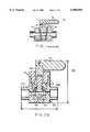
- FIG. 1shows a spring clip stopcock valve 10 that is designed for use in certain special procedures in hospitals and laboratories. That illustrated valve is exemplary of the types of valves presently used in connection with endoscopic and laparoscopic procedures.
- spring clip stopcock valve 10includes body 12, plug valve member 14, handle 16 and spring clip 18.
- Spring clip 18is arranged about body 12 so as to retain the plug valve member 14 in the body.
- Plug valve member 14is frusto-conical in design and extends through apertures in the top and bottom of the body 12. Leak-tightness is attempted by maintaining close tolerances between the valve member and the body cavity receiving the valve member and through use of lubricating material to occlude space between opposing surfaces of those components. These prior valves however often leaked during use, creating an unclean and unsanitary environment and, more seriously, posing grave health concerns such as the transmission of HIV, hepatitis and the like to medical personnel.
- valves used for endoscopic and laparoscopic proceduresare described in U.S. Pat. Nos. 4,263,897; 4,567,880; 4,668,215; 5,290,308; 5,292,305; 5,322,503; 5,347,992 and U.S. Pat. No. 5,490,836.
- the valves usedare similar to those described above or are complex valve assemblies (e.g., spring loaded valves) involving numerous components.
- the present inventionprovides an on-off valve that is particularly useful in medical procedures and in laboratory devices.
- the valve of the inventionessentially or even completely eliminates leakage and can be easily repaired, maintained, cleaned and sterilized.
- Valves of the inventionare especially useful with medical instruments, particularly endoscopic and laparoscopic procedures.
- the inventionalso provides medical instruments, particularly endoscopic and laparoscopic devices that comprises the described valve.
- the on-off valve of the instant inventionis especially useful in connection with medical procedures, medical instruments and laboratory devices, this is not a limitation as to the possible uses for such a valve(s).
- such valvescan be used with any device, instrument and/or system, including those that use Luer fittings or tubing/tubing connections.
- Preferred valves of the inventioninclude a valve body, a valve member, and a flexible seal member, where the body includes a centrally disposed cavity and two through apertures that communicate with the cavity.
- the flexible seal memberincludes an internal chamber and two through-flow apertures.
- the internal chamberis configured to rotatably receive a portion of the valve member, the portion including the internal passage.
- the seal memberis mounted on the valve member and the assembly of the flexible seal member and the valve member is disposed within the body cavity.
- the seal memberis made from BUNA-N material.
- seal member hardnesspreferably lies in the range of from about SHORE A 30 to about SHORE A 60, more preferably a hardness of from about SHORE A 45 to about SHORE A 55.
- a hardness of about SHORE A 50is particularly preferred.
- the valvealso includes a compression mechanism that acts on a surface of the seal member after it is disposed in the seal cavity. That mechanism compresses the seal member so it sealingly engages opposing surfaces of the valve member and the body.
- the valvefurther includes a rotating mechanism that is interconnected to the valve member. Forces applied to a portion of the rotating mechanism cause the valve member to be selectively rotated in either a clockwise or counterclockwise direction. The rotation of the valve member selectively opens and closes the valve.
- the seal memberincludes a coating material on at least the surface of the seal member internal chamber so as to reduce the coefficient of friction between the valve member and the seal member.
- the coating materialpreferably has a melt temperature well above the temperatures used for sterilizing equipment used in medical procedures.
- the coatingis a permanent coating that is deposited or applied to the seal member.
- a permanent coatingreduces or can eliminate the need to re-apply a material after each use of the valve as currently done with lubricating-type valves discussed above.
- a permanent coatingalso avoids transmission of a lubricating material to a patient.
- Preferred permanent coatingsare polymers such as a poly(vinylphenyl) or other poly(aromatic) material. Parylene (e.g., parlyene N) is particularly preferred.
- a vacuum deposition or sputtering processis a preferred method for application of a permanent coating onto a seal member. Also, in less preferred aspects of the invention, any of a number of acceptable lubricants can be used in place of or in addition to a permanent coating.
- a valve according to the instant inventionis capable of withstanding fluid pressures of up to about 110 psig or more, or even 150 psig or more whereas prior art valves used with endoscopic instruments typically are limited to pressures on the order of about 40 psig.
- the seal member coatingreduces the frictional forces between the valve member and the seal member so the valve member rotates smoothly thereby minimizing discomfort and possible injury to the patient.
- a permanent material coating, such as parylene Nis also advantageous in that it does not lose its low coefficient of friction characteristic when subjected to sterilization and cleaning conditions used for surgical instruments.
- Valves of the inventionalso can be easily disassembled and reassembled by a user without requiring special equipment or requiring detailed and complicated procedures. Further, a worn seal member can be easily removed and replaced with a fresh seal member to maintain a leak-tight condition of the valve.
- FIG. 1is a cross sectional side view of a spring clip stopcock valve
- FIG. 2Ais a cross sectional side view of a valve according to the instant invention.
- FIG. 2Bis a cross sectional side view of an alternate handle/stem attachment for the valve of FIG. 2A;
- FIG. 3Ais a cross sectional side view of the body for the valve of FIG. 2;
- FIG. 3Bis a top view of the body for the valve of FIG. 2;
- FIG. 4Ais a top view of the seal member for the valve of FIG. 2;
- FIG. 4Bis a cross sectional side view of the seal member of FIG. 4A;
- FIG. 4Cis a side view of the seal member of FIG. 4A;
- FIG. 5Ais a top view of the washer for the valve of FIG. 2;
- FIG. 5Bis a side view of the washer of FIG. 5A;
- FIG. 5Cis a bottom view of the washer of FIG. 5A;
- FIG. 6is a cross sectional side view of the valve stem for the valve of FIG. 2;
- FIG. 7is a cross sectional side view of the valve member for the valve of FIG. 2;
- FIG. 8is an exemplary endoscopic instrument with the valve of FIGS. 2A-2B.
- FIG. 9is an exemplary laparoscopic instrument with the valve of FIGS. 2A-2B.
- FIG. 2Ashows a cross sectional side view of a preferred valve 100 according to the instant invention. Specific views for certain components of valve 100 also are shown in FIGS. 2B, 3A-B, 4A-C, 5A-C and FIGS. 6-7. As such, reference should be made to these figures in the following discussion. Also, references herein to an endoscopic instrument or procedure shall be understood to be generally inclusive of laparoscopic or other of the less invasive micro-surgery devices or procedures.
- Valve 100preferably is a quarter-turn valve and includes body 102, seal member 104, valve member 106, valve stem 108 and handle 110.
- the valve stem and handle 110are typically secured together by a pin passing through a hole 164 in the valve stem and a corresponding hole in the handle.
- the handle 110can be secured to the stem 108 using any one of a number of available techniques. For example, as shown in FIG. 2B, a handle 110a can be secured to a stem 108a by means of a threaded connection 111.
- handle 110is rotated clockwise or counterclockwise (a quarter turn in the preferred quarter-turn embodiment) to selectively cause the valve member 106 to rotate in a similar fashion, thereby opening or closing the valve.
- the valvealso preferably includes washer 112 and threaded cap 114 that cooperate, as discussed below, to compress the seal member 104 so it sealingly engages interior surfaces of the body 102 and exterior surfaces of valve member 106. In this way, a leak-tight condition is established.
- body 102, valve member 106, valve stem 108, handle 110, washer 112 and cap 114are stainless steel (e.g. 304 SS or 316 SS).
- any or all of these partscan be made from any of a number of biocompatible materials including plastics, that have the strength and chemical resistive properties for the intended use.
- a rigid polypropylenecould be employed.
- a rigid plasticmay be preferred if the valve is intended for single use applications.
- Other metalsalso may be employed, but are generally less preferred than stainless steel.
- Body 102includes inlet and outlet connections 122a,b, which interconnect valve 100 to piping, tubing, endoscopic instrument or the like. Although these connections are illustrated as being threaded, each connection can be any of a number of connection types available and known to those skilled in the art.
- the inlet and outlet connection 122acan be configured with a male or female Luer connection detail.
- These connections 122a,beach include an internal flow passage that communicates with seal cavity 120 internal to valve body 102.
- Valve body 102also includes top opening 124 that communicates with seal cavity 120.
- the top openingis sized so an assembly comprising valve member 106 and seal member 104 can be introduced therethrough.
- the top openingincludes a female thread connection to threadably engage the threads of cap 114.
- the top opening and capcan be configured so as to be secured to each other in any of a number of ways including a snap-lock type of connection.
- the connectionremovably secures cap 114 to valve body 102 so the user can easily disassemble the valve 100 to replace any damaged or worn parts as well as to perform any desired maintenance activities. It is, however, within the scope of the instant invention for cap 114 to be secured in a permanent manner to the valve body 102.
- Seal cavity 120is configured to receive an assembly of the seal and valve members 104,106.
- seal cavity 120 and seal member 104are cylindrically shaped so an axial compression of the seal member causes a radial expansion of the seal member.
- Seal cavity 120also is configured so its bottom and side surfaces sealingly engage the opposing surfaces of the seal member when the seal member is axially compressed therein.
- the configuration and cross-section of seal cavity 120are established to make insertion of the valve/seal member assembly easy and simple yet assure that a leak tight connection can be made when the seal member is axially compressed.
- the difference between the inner diameter of the seal cavity and the outer diameter of the seal memberis about 2 mils.
- Seal member 104preferably is a flexible, resilient, bio-compatible material such as BUNA-N (Nitrile) having a hardness in the range of from about SHORE A 30 to about SHORE A 60 and more particularly a hardness of about SHORE A 50.
- seal member 104can be any of a number of flexible materials such as a fluorocarbon such as VITON, neoprene(chloroprene) and the like that can be manufactured with the required shape and have the required material hardness or softness.
- Seal member 104includes an internal cavity 130 that is configured to generally conform to the spherical shape of the ball-end 150 of the valve member.
- the exposed surfaces of the seal member internal cavity 130are coated with a material 138 to reduce frictional forces between valve member 106 and seal member 104 and thereby reduce the torque required to rotate the valve.
- material 138preferably is a bio-compatible material that is deposited or applied onto the seal member using any of a number of manufacturing techniques so as to essentially form a permanent coating.
- a vacuum depositionis particularly preferred.
- Material 138preferably has a low coefficient of friction, as compared to that for the seal member material, and a melting temperature that is well above the temperatures typically used for sterilization (e.g., a melt temperature of at least about 20-30° C. greater than 135° C.).
- the material coating 138is a polymer such as a poly(vinylphenyl) or other poly(aromatic). More preferably, the polymer coating is parylene such as Parylene N.
- a coating of Parylene Nreduces the torque required to be developed for rotation by about 300-500% as compared to that required to rotate the valve member 106 in the "dry" or non-coated state. This makes the rotation of valve member 106 easy and smooth, thereby minimizing the potential discomfort or damage that could arise because of a sudden or erratic motion that might occur during the course of a surgical procedure.
- valve 100also allows valve 100 to be sterilized repeatedly without degrading the low frictional characteristic of the material.
- the valve with such a coatingdoes not have to be disassembled and reassembled after sterilization or cleaning to establish the low friction condition.
- prior valvestypically require application of a lubricant after each cleaning procedure.
- the valve 100can be operated at such temperatures without degrading the material's low frictional characteristic.
- seal member internal cavity 130Although coating of seal member internal cavity 130 is illustrated, this is not a limitation. The amount of coverage of the coating is dependent upon a number of factors and considerations including simplification of the coating process, e.g., coating of all the exposed surfaces of seal member 104, and covering those surface(s) that would have a direct impact on minimizing the torque required to rotate the valve.
- a lubricantmay be employed, for example vaseline, that is appropriate for the intended use and preferably having any required governmental approvals (e.g., FDA certification). Because of the simplified design for the valve 100 of the instant invention, the process of disassembling and re-assembling, including lubricating the valve, is simplified. Although generally unnecessary and less preferred, a lubricant also may be used in a valve that contains a permanent coating as discussed above.
- seal member 104is mounted on valve member 104 prior to insertion of the valve/seal member assembly into the body 102. This mounting is accomplished by passing valve member ball end 150 through the seal member top opening 134 so it passes into and remains disposed within seal member internal cavity 130. Seal member top opening 134 is sized so it is greater than or equal to the outer diameter of valve member stem portion 154 that extends therethrough. The resiliency of the material for seal member 104 allows seal member top opening 134 to deform so ball end 150 can pass therethrough and then return to the original configuration for seal member top opening 134.
- the resiliency of the materialalso allows seal member 104 to be easily dismounted from valve member 104.
- Thismakes the replacement of a worn seal member 104 by the user easy and simple.
- the seal memberconforms to valve member ball end 150 following axial compression, a leak-tight condition is easily re-established by a replacement seal member 104.
- Thisis in contrast with known prior art valves that rely on tight tolerances and the presence of the lubricating medium to form a leak-tight condition.
- replacement partstend to make the valve prone to leakage more than that seen with originally manufactured valves.
- valve body seal cavity 120preferably includes at least one pair of diametrically opposed arcuate notches 126 and the seal member includes a pair of diametrically opposed arcuate notches 136.
- Arcuate notches 126 in the valve body seal cavityextend downward from internal lip 128 on which washer 112 rests when the valve is completely assembled.
- Seal member arcuate notches 136extend downward from the top surface of seal member 104, the surface which comes into contact with a face 148 of washer disk 140.
- Two diametrically opposed legs 146also extend from this face 148 of washer disk 140. When the valve is completely assembled, as is illustrated in FIG. 2, these legs 146 engage the arcuate notches 126,136 in both valve body 102 and seal member 104. In this way, flow openings 132a,b in seal member 104 are aligned with the flow passages for the inlet and outlet connections 122a,b in the valve body 102. In addition to localizing and orientating seal member 104 within valve body 102, the engagement of legs 146 with arcuate notches 126,136 also assures that seal member 104 is restrained from movement while rotating valve member 106.
- Legs 146preferably are cylindrically shaped extensions from the surface 148 of the washer and each arcuate notch 136 in the seal member 104 preferably forms an essentially hollow cylinder with a corresponding notch 126 in the valve body seal cavity 120. Legs 146 can be arranged on surface 148 so they are stepped in from the outside diameter of disk 140 or lined up with the disk's outside diameter as illustrated in FIGS. 5A-C.
- Washer 112also preferably includes a depressed region 144 that generally corresponds to a 90° arc.
- the depressed region 144cooperates with a finger portion 162 of stem 108 to control the rotation of the stem responsive to the rotary motion of handle 110.
- finger portion 162engages the side walls of the depressed region 144 to limit rotational motion in either a clockwise or counterclockwise direction.
- valve member stem portion 154is secured within the hollow portion 160 of stem 108, such as by an interference fit, valve member 106 also rotates responsively to the rotary motion of handle 110.
- Depressed region 144also is arranged on disk 140 with respect to the legs 146. Additionally, valve member 106 is secured to stem 108 so there is a set relationship between finger portion 162 and valve member internal passage 152. In this way, valve member internal passage 152 is localized and orientated with respect to the flow passages in the valve body inlet and outlet connections 122a,b when the legs 146 of washer 112 engage the valve body notches 126. This renders the user's re-assembly of the valve following maintenance activities simple and easy.
- valve 100 of the instant inventioncan be broken down into two assemblies or groupings: valve body 102 and a valve/seal assembly that includes seal member 104, valve member 106, stem 108, handle 110, washer 112 and cap 114.
- a userunscrews cap 114 from valve body top opening 124 and removes the valve/seal assembly therefrom. The user then can perform whatever maintenance or repair activity is required, for example, the user replaces a worn seal member with a new one. As described above, a seal member is replaced by dis-mounting and mounting it on the valve member.
- valve/seal assemblyFor reassembly, the user inserts the valve/seal assembly into the valve body top opening 124 and orientates the assembly so legs 146 are aligned with arcuate notches 126 in the valve body seal cavity 120. When the valve/seal assembly is properly orientated, the user screws cap 114 into top opening 124 until surface 148 of washer 112 contacts internal lip 128 of valve body 102.
- surface 148 of washer 112also acts on the top surface of the seal member so as to axially compress the seal member 104 within the valve body seal cavity 120.
- the axial compressionin turn causes seal member 104 to expand outwardly to sealingly engage the interior surfaces of seal cavity 120.
- Seal member 104also expands inwardly towards valve member ball end 150 so as to sealingly engage the opposing surfaces of the ball end. That engagement establishes the leak-tight condition.
- Re-assembly of valves of the inventionis also convenient because parts may be readily interchanged after disassembly and cleaning without compromise of the sealing characteristics of the valve.
- the elasticity of sealfacilitates interchange or replacement of ball and body components without reduction of sealing properties.
- prior plug-type valves as discussed aboverequire exact matching of components upon re-assembly to attempt to maintain desired sealing properties.
- FIG. 8shows an exemplary endoscopic instrument 200 of the invention, which comprises a valve 100 as described above.
- FIG. 9shows an exemplary laparoscopic instrument 300, which also includes valve 100 of the invention.
- Flushing devicesirrigation and evacuation
- irrigation and evacuationare generally preferred endoscopic surgical instruments of the invention, wherein fluid flows through valve 100 both into and out of a patient.
- separate valves of the inventioncan be used for irrigation and evacuation functions. Such devices are described in general in the above-mentioned U.S. patents, where the valve of the present invention may be substituted for a prior valve.
- valve 100is illustrated as being used with specific instruments and correspondingly with specific procedures, the valve 100 can be used in any of a number of endoscopic procedures and with any of a number of instruments used in connection with these procedures.
- valves of the invention used for endoscopic proceduresare small but can be easily operated by individuals.
- the diameter of the spherical or ball end 150 of the valve member 106suitably lies in the range of from about 80 to 170 mils, more preferably 90 to 160 mils.
- the diameter of the internal flow passage 152 therethroughlies in the range of from about 45 to 80 mils, more preferably 50 mils to about 80 mils.
- the diameter of the ball end and the internal flow passagesuitably may be larger, for example a ball end 150 diameter of from 200 to 800 mils and a flow passage diameter of from about 100 to 250 mils.
- a 250 mil ball end diameter and a 130 mil diameter flow passagemay be particularly suitable for laboratory applications, e.g. for transfer of solvents or other fluids.
- Larger valvesalso may be appropriate for laboratory use, e.g. an about 500 mils (i.e., 1/2 in.) ball end diameter with a correspondingly larger diameter flow passage.
- a particularly preferred valve of the inventionhas a length (without adapter or connector fittings that may be employed as desired; length y in FIG. 2A) of 3/8 inches and width of 3/8 inches, a height (height z in FIG. 2B) of 7/8 inches, a ball end diameter of 156 mils and a 78 mil diameter flow passage.
- valve of the instant inventionin terms of its use as a valve for endoscopic instruments or procedures, this is not a limitation. It is within the scope of the instant invention for the above described valve to be used in connection with any medical procedure or device, for example, use with any irrigation device. Further, the valve of the instant invention can be used in laboratories for medical and non-medical tests or experiments. Moreover, the valve can be used with any device or in any system that uses Luer fittings/connections or tubing/tubing connections.
- Valves of the inventioncan be manufactured by known procedures. For example, a stainless steel or other metal valve is suitable milled. A seven-axis CITIZEN machining center may be particularly suitable for milling production of a valve of the invention.
- a seal membermay be suitably formed through a molding process.
- a plastic valve assemblymay be suitably produced by an extrusion or an inset mold process, more typically a mold process. It also may be desirable to surface treat a valve, e.g. to subject a stainless steel or other metal valve to a passivation process such as a nitric acid treatment.
- valves of the inventionpreferably are non-integral with systems in which they are used, i.e. the entire valve assembly can be readily removed from a surgical or laboratory instrument or system such as by disconnecting tubing or a fitting.
Landscapes
- Health & Medical Sciences (AREA)
- Heart & Thoracic Surgery (AREA)
- Pulmonology (AREA)
- Engineering & Computer Science (AREA)
- Anesthesiology (AREA)
- Biomedical Technology (AREA)
- Hematology (AREA)
- Life Sciences & Earth Sciences (AREA)
- Animal Behavior & Ethology (AREA)
- General Health & Medical Sciences (AREA)
- Public Health (AREA)
- Veterinary Medicine (AREA)
- Surgical Instruments (AREA)
Abstract
Description
Claims (12)
Priority Applications (4)
| Application Number | Priority Date | Filing Date | Title |
|---|---|---|---|
| US08/726,149US6090094A (en) | 1996-10-04 | 1996-10-04 | Ball valves and uses thereof including endoscopic surgical instruments |
| EP97943594AEP0952865A2 (en) | 1996-10-04 | 1997-09-25 | Ball valves and uses thereof including endoscopic surgical instruments |
| AU45031/97AAU4503197A (en) | 1996-10-04 | 1997-09-25 | Ball valves and uses thereof including endoscopic surgical instruments |
| PCT/US1997/017283WO1998014109A2 (en) | 1996-10-04 | 1997-09-25 | Ball valves and uses thereof including endoscopic surgical instruments |
Applications Claiming Priority (1)
| Application Number | Priority Date | Filing Date | Title |
|---|---|---|---|
| US08/726,149US6090094A (en) | 1996-10-04 | 1996-10-04 | Ball valves and uses thereof including endoscopic surgical instruments |
Publications (1)
| Publication Number | Publication Date |
|---|---|
| US6090094Atrue US6090094A (en) | 2000-07-18 |
Family
ID=24917445
Family Applications (1)
| Application Number | Title | Priority Date | Filing Date |
|---|---|---|---|
| US08/726,149Expired - Fee RelatedUS6090094A (en) | 1996-10-04 | 1996-10-04 | Ball valves and uses thereof including endoscopic surgical instruments |
Country Status (4)
| Country | Link |
|---|---|
| US (1) | US6090094A (en) |
| EP (1) | EP0952865A2 (en) |
| AU (1) | AU4503197A (en) |
| WO (1) | WO1998014109A2 (en) |
Cited By (42)
| Publication number | Priority date | Publication date | Assignee | Title |
|---|---|---|---|---|
| WO2003093704A1 (en)* | 2002-05-03 | 2003-11-13 | Acist Medical Systems, Inc. | Gamma-stable high pressure stopcock |
| US20040167559A1 (en)* | 2001-08-14 | 2004-08-26 | Taylor Scott V. | Access sealing apparatus and method |
| US20050033246A1 (en)* | 2002-05-14 | 2005-02-10 | Ahlberg Russell E. | Surgical device with tack-free gel and method of manufacture |
| US20050054995A1 (en)* | 2003-09-09 | 2005-03-10 | Barzell Winston E. | System and method for irrigation and tissue evacuation and collection |
| US20060229499A1 (en)* | 2004-04-24 | 2006-10-12 | Peter Eisenkolb | Medical-technology valve device for suction and/or flushing lines of medical instruments |
| WO2007038299A3 (en)* | 2005-09-23 | 2009-04-23 | Glad Products Co | Valve element |
| US20090187146A1 (en)* | 2007-12-19 | 2009-07-23 | Vance Products Inc. D/B/A Cook Urological Incorporated | Vacuum aspiration handle |
| US20100056867A1 (en)* | 2004-12-08 | 2010-03-04 | Vision - Sciences Inc. | Endoscope Valve |
| US20140074136A1 (en)* | 1997-09-04 | 2014-03-13 | Smith & Nephew, Inc. | Surgical cutting device and method for its use |
| CN103672006A (en)* | 2012-09-26 | 2014-03-26 | 株式会社富士金 | Ball valve |
| US9636130B2 (en) | 2001-10-26 | 2017-05-02 | Covidien Lp | Reciprocating rotary arthroscopic surgical instrument |
| US9936861B2 (en) | 2004-08-27 | 2018-04-10 | Covidien Lp | Tissue resecting system |
| US10251539B2 (en) | 2010-09-28 | 2019-04-09 | Covidien Lp | Hysteroscopic system |
| US10299819B2 (en) | 2016-07-28 | 2019-05-28 | Covidien Lp | Reciprocating rotary surgical cutting device and system for tissue resecting, and method for its use |
| US10631889B2 (en) | 2014-12-16 | 2020-04-28 | Covidien Lp | Surgical device with incorporated tissue extraction |
| US10772652B2 (en) | 2015-01-28 | 2020-09-15 | Covidien Lp | Tissue resection system |
| US10772654B2 (en) | 2017-03-02 | 2020-09-15 | Covidien Lp | Fluid-driven tissue resecting instruments, systems, and methods |
| US10799264B2 (en) | 2015-06-18 | 2020-10-13 | Covidien Lp | Surgical instrument with suction control |
| US10842350B2 (en) | 2015-06-17 | 2020-11-24 | Covidien Lp | Endoscopic device with drip flange and methods of use thereof for an operative procedure |
| US10869684B2 (en) | 2018-02-13 | 2020-12-22 | Covidien Lp | Powered tissue resecting device |
| US10898218B2 (en) | 2019-02-25 | 2021-01-26 | Covidien Lp | Tissue resecting device including a motor cooling assembly |
| US10945752B2 (en) | 2019-03-20 | 2021-03-16 | Covidien Lp | Tissue resecting instrument including a rotation lock feature |
| US11065147B2 (en) | 2018-10-18 | 2021-07-20 | Covidien Lp | Devices, systems, and methods for pre-heating fluid to be introduced into a patient during a surgical procedure |
| US11083481B2 (en) | 2019-02-22 | 2021-08-10 | Covidien Lp | Tissue resecting instrument including an outflow control seal |
| US11154318B2 (en) | 2019-02-22 | 2021-10-26 | Covidien Lp | Tissue resecting instrument including an outflow control seal |
| US11179172B2 (en) | 2019-12-05 | 2021-11-23 | Covidien Lp | Tissue resecting instrument |
| US11197710B2 (en) | 2018-10-26 | 2021-12-14 | Covidien Lp | Tissue resecting device including a blade lock and release mechanism |
| US11317947B2 (en) | 2020-02-18 | 2022-05-03 | Covidien Lp | Tissue resecting instrument |
| US11376032B2 (en) | 2019-12-05 | 2022-07-05 | Covidien Lp | Tissue resecting instrument |
| US11452806B2 (en) | 2019-10-04 | 2022-09-27 | Covidien Lp | Outflow collection vessels, systems, and components thereof for hysteroscopic surgical procedures |
| US11547782B2 (en) | 2020-01-31 | 2023-01-10 | Covidien Lp | Fluid collecting sheaths for endoscopic devices and systems |
| US11547815B2 (en) | 2018-05-30 | 2023-01-10 | Covidien Lp | Systems and methods for measuring and controlling pressure within an internal body cavity |
| US11553977B2 (en) | 2019-05-29 | 2023-01-17 | Covidien Lp | Hysteroscopy systems and methods for managing patient fluid |
| US11571233B2 (en) | 2020-11-19 | 2023-02-07 | Covidien Lp | Tissue removal handpiece with integrated suction |
| US11596429B2 (en) | 2020-04-20 | 2023-03-07 | Covidien Lp | Tissue resecting instrument |
| US11737777B2 (en) | 2020-02-05 | 2023-08-29 | Covidien Lp | Tissue resecting instruments |
| US11883058B2 (en) | 2019-03-26 | 2024-01-30 | Covidien Lp | Jaw members, end effector assemblies, and ultrasonic surgical instruments including the same |
| US11890237B2 (en) | 2019-10-04 | 2024-02-06 | Covidien Lp | Outflow collection vessels, systems, and components thereof for hysteroscopic surgical procedures |
| US12156673B2 (en) | 2020-10-07 | 2024-12-03 | Covidien Lp | Temperature measurement device for a handpiece of a surgical instrument |
| US12303109B2 (en) | 2021-12-22 | 2025-05-20 | Covidien Lp | Surgical systems and methods for component cooling while warming fluid to be introduced during a surgical procedure |
| US12350462B1 (en)* | 2020-11-04 | 2025-07-08 | Northgate Technologies, Inc. | Smoke suction flow regulator |
| US12364500B2 (en) | 2021-05-26 | 2025-07-22 | Covidien Lp | Tissue resecting instrument |
Citations (29)
| Publication number | Priority date | Publication date | Assignee | Title |
|---|---|---|---|---|
| US2117456A (en)* | 1934-12-22 | 1938-05-17 | Akron Brass Mfg Company Inc | Valve construction |
| US3100501A (en)* | 1960-12-23 | 1963-08-13 | Crane Co | Removable head and seat ball valve construction |
| US3223111A (en)* | 1963-09-27 | 1965-12-14 | Acf Ind Inc | Integral valve and seat unit |
| US3434691A (en)* | 1964-10-12 | 1969-03-25 | Clark H Hamilton | Valve |
| US3648723A (en)* | 1969-12-22 | 1972-03-14 | Goddard Ind Inc | Valve |
| US3735956A (en)* | 1972-04-10 | 1973-05-29 | Whitey Research Tool Co | Ball valve and improved seat arrangement |
| US3827439A (en)* | 1972-10-30 | 1974-08-06 | Heyer Schulte Corp | Plug valve for physiological shunt systems |
| US4026516A (en)* | 1970-05-28 | 1977-05-31 | Whitey Research Tool Co. | Ball valve stem guide |
| US4184510A (en)* | 1977-03-15 | 1980-01-22 | Fibra-Sonics, Inc. | Valued device for controlling vacuum in surgery |
| US4263897A (en)* | 1979-05-04 | 1981-04-28 | Olympus Optical Co., Ltd. | Endoscope |
| US4397617A (en)* | 1980-05-12 | 1983-08-09 | Consiglio Nazionale Delle Ricerche | Heart pump for the circulation of blood outside the body of a living subject |
| US4441524A (en)* | 1980-10-02 | 1984-04-10 | Fuji Kinzoku Kohsaku Co. Ltd. | Ball valve |
| US4567880A (en)* | 1984-12-26 | 1986-02-04 | Goodman Tobias M | Endoscopic device with three-way valve |
| US4573498A (en)* | 1984-03-29 | 1986-03-04 | General Signal Corporation | Ball valve |
| US4604090A (en)* | 1983-11-22 | 1986-08-05 | Consolidated Controls Corporation | Compact implantable medication infusion device |
| US4668215A (en)* | 1986-05-15 | 1987-05-26 | Dexide, Inc. | Irrigator-evacuator control for surgical procedures |
| US4681560A (en)* | 1984-03-16 | 1987-07-21 | Pudenz-Schulte Medical Research Corp. | Subcutaneous infusion reservoir and pump system |
| US4703775A (en)* | 1985-09-16 | 1987-11-03 | Abbott Laboratories | Liquid flow regulator |
| US4819637A (en)* | 1987-09-01 | 1989-04-11 | Interventional Therapeutics Corporation | System for artificial vessel embolization and devices for use therewith |
| US5247960A (en)* | 1991-04-24 | 1993-09-28 | Abb Atom Ab | Replacement valve seat device with expandable ring |
| US5286258A (en)* | 1991-03-08 | 1994-02-15 | Habley Medical Technology Corporation | Multipharmaceutical delivery system |
| US5290308A (en)* | 1992-07-15 | 1994-03-01 | Edward Weck Incorporated | Endoscopic instrument |
| US5292305A (en)* | 1991-09-10 | 1994-03-08 | Cordis Corporation | Double-lumen angioscopy catheter |
| US5312332A (en)* | 1992-10-09 | 1994-05-17 | Symbiosis Corporation | Endoscopic surgical methods utilizing a suction-irrigation instrument with a port for endoscopic manipulating instruments |
| US5322503A (en)* | 1991-10-18 | 1994-06-21 | Desai Ashvin H | Endoscopic surgical instrument |
| US5347992A (en)* | 1993-01-22 | 1994-09-20 | Karl Storz Endoscopy America, Inc. | Single axis three way selector valve for endoscopes |
| US5356394A (en)* | 1992-10-09 | 1994-10-18 | Kevin Farley | Cannula with ball valve |
| US5380320A (en)* | 1993-11-08 | 1995-01-10 | Advanced Surgical Materials, Inc. | Electrosurgical instrument having a parylene coating |
| US5490836A (en)* | 1991-10-18 | 1996-02-13 | Desai; Ashvin H. | Endoscopic surgical instrument |
Family Cites Families (1)
| Publication number | Priority date | Publication date | Assignee | Title |
|---|---|---|---|---|
| US4434691A (en)* | 1982-04-12 | 1984-03-06 | Gerber Garment Technology, Inc. | Method and apparatus for sealing cut sheet material |
- 1996
- 1996-10-04USUS08/726,149patent/US6090094A/ennot_activeExpired - Fee Related
- 1997
- 1997-09-25AUAU45031/97Apatent/AU4503197A/ennot_activeAbandoned
- 1997-09-25EPEP97943594Apatent/EP0952865A2/ennot_activeWithdrawn
- 1997-09-25WOPCT/US1997/017283patent/WO1998014109A2/ennot_activeApplication Discontinuation
Patent Citations (29)
| Publication number | Priority date | Publication date | Assignee | Title |
|---|---|---|---|---|
| US2117456A (en)* | 1934-12-22 | 1938-05-17 | Akron Brass Mfg Company Inc | Valve construction |
| US3100501A (en)* | 1960-12-23 | 1963-08-13 | Crane Co | Removable head and seat ball valve construction |
| US3223111A (en)* | 1963-09-27 | 1965-12-14 | Acf Ind Inc | Integral valve and seat unit |
| US3434691A (en)* | 1964-10-12 | 1969-03-25 | Clark H Hamilton | Valve |
| US3648723A (en)* | 1969-12-22 | 1972-03-14 | Goddard Ind Inc | Valve |
| US4026516A (en)* | 1970-05-28 | 1977-05-31 | Whitey Research Tool Co. | Ball valve stem guide |
| US3735956A (en)* | 1972-04-10 | 1973-05-29 | Whitey Research Tool Co | Ball valve and improved seat arrangement |
| US3827439A (en)* | 1972-10-30 | 1974-08-06 | Heyer Schulte Corp | Plug valve for physiological shunt systems |
| US4184510A (en)* | 1977-03-15 | 1980-01-22 | Fibra-Sonics, Inc. | Valued device for controlling vacuum in surgery |
| US4263897A (en)* | 1979-05-04 | 1981-04-28 | Olympus Optical Co., Ltd. | Endoscope |
| US4397617A (en)* | 1980-05-12 | 1983-08-09 | Consiglio Nazionale Delle Ricerche | Heart pump for the circulation of blood outside the body of a living subject |
| US4441524A (en)* | 1980-10-02 | 1984-04-10 | Fuji Kinzoku Kohsaku Co. Ltd. | Ball valve |
| US4604090A (en)* | 1983-11-22 | 1986-08-05 | Consolidated Controls Corporation | Compact implantable medication infusion device |
| US4681560A (en)* | 1984-03-16 | 1987-07-21 | Pudenz-Schulte Medical Research Corp. | Subcutaneous infusion reservoir and pump system |
| US4573498A (en)* | 1984-03-29 | 1986-03-04 | General Signal Corporation | Ball valve |
| US4567880A (en)* | 1984-12-26 | 1986-02-04 | Goodman Tobias M | Endoscopic device with three-way valve |
| US4703775A (en)* | 1985-09-16 | 1987-11-03 | Abbott Laboratories | Liquid flow regulator |
| US4668215A (en)* | 1986-05-15 | 1987-05-26 | Dexide, Inc. | Irrigator-evacuator control for surgical procedures |
| US4819637A (en)* | 1987-09-01 | 1989-04-11 | Interventional Therapeutics Corporation | System for artificial vessel embolization and devices for use therewith |
| US5286258A (en)* | 1991-03-08 | 1994-02-15 | Habley Medical Technology Corporation | Multipharmaceutical delivery system |
| US5247960A (en)* | 1991-04-24 | 1993-09-28 | Abb Atom Ab | Replacement valve seat device with expandable ring |
| US5292305A (en)* | 1991-09-10 | 1994-03-08 | Cordis Corporation | Double-lumen angioscopy catheter |
| US5322503A (en)* | 1991-10-18 | 1994-06-21 | Desai Ashvin H | Endoscopic surgical instrument |
| US5490836A (en)* | 1991-10-18 | 1996-02-13 | Desai; Ashvin H. | Endoscopic surgical instrument |
| US5290308A (en)* | 1992-07-15 | 1994-03-01 | Edward Weck Incorporated | Endoscopic instrument |
| US5356394A (en)* | 1992-10-09 | 1994-10-18 | Kevin Farley | Cannula with ball valve |
| US5312332A (en)* | 1992-10-09 | 1994-05-17 | Symbiosis Corporation | Endoscopic surgical methods utilizing a suction-irrigation instrument with a port for endoscopic manipulating instruments |
| US5347992A (en)* | 1993-01-22 | 1994-09-20 | Karl Storz Endoscopy America, Inc. | Single axis three way selector valve for endoscopes |
| US5380320A (en)* | 1993-11-08 | 1995-01-10 | Advanced Surgical Materials, Inc. | Electrosurgical instrument having a parylene coating |
Non-Patent Citations (1)
| Title |
|---|
| Product Literature, E/M Corporation.* |
Cited By (81)
| Publication number | Priority date | Publication date | Assignee | Title |
|---|---|---|---|---|
| US9427247B2 (en) | 1997-09-04 | 2016-08-30 | Smith & Nephew, Inc. | Surgical cutting device and method for its use |
| US9089358B2 (en)* | 1997-09-04 | 2015-07-28 | Smith & Nephew, Inc. | Surgical cutting device and method for its use |
| US20140074136A1 (en)* | 1997-09-04 | 2014-03-13 | Smith & Nephew, Inc. | Surgical cutting device and method for its use |
| US20040167559A1 (en)* | 2001-08-14 | 2004-08-26 | Taylor Scott V. | Access sealing apparatus and method |
| US8703034B2 (en) | 2001-08-14 | 2014-04-22 | Applied Medical Resources Corporation | Method of making a tack-free gel |
| US7727255B2 (en) | 2001-08-14 | 2010-06-01 | Applied Medical Resources Corporation | Access sealing apparatus and method |
| US10441306B2 (en) | 2001-10-26 | 2019-10-15 | Covidien Lp | Reciprocating rotary arthroscopic surgical instrument |
| US9636130B2 (en) | 2001-10-26 | 2017-05-02 | Covidien Lp | Reciprocating rotary arthroscopic surgical instrument |
| JP2005524804A (en)* | 2002-05-03 | 2005-08-18 | アシスト メディカル システムズ,インク. | High-pressure stopcock that is stable to gamma rays |
| WO2003093704A1 (en)* | 2002-05-03 | 2003-11-13 | Acist Medical Systems, Inc. | Gamma-stable high pressure stopcock |
| JP2009257595A (en)* | 2002-05-03 | 2009-11-05 | Acist Medical Systems Inc | Gamma stable high pressure stopcock |
| US6880808B2 (en)* | 2002-05-03 | 2005-04-19 | Acist Medical Systems, Inc. | Gamma-stable high pressure stopcock |
| US20050033246A1 (en)* | 2002-05-14 | 2005-02-10 | Ahlberg Russell E. | Surgical device with tack-free gel and method of manufacture |
| US20070213666A1 (en)* | 2003-09-09 | 2007-09-13 | Civco Medical Instruments Co., Inc. | System and method for irrigation and tissue evacuation and collection |
| US7172579B2 (en) | 2003-09-09 | 2007-02-06 | Civco Medical Instruments Co., Inc. | System and method for irrigation and tissue evacuation and collection |
| US20050054995A1 (en)* | 2003-09-09 | 2005-03-10 | Barzell Winston E. | System and method for irrigation and tissue evacuation and collection |
| US20060229499A1 (en)* | 2004-04-24 | 2006-10-12 | Peter Eisenkolb | Medical-technology valve device for suction and/or flushing lines of medical instruments |
| US10939810B2 (en) | 2004-08-27 | 2021-03-09 | Covidien Lp | Tissue resecting system |
| US10076237B2 (en) | 2004-08-27 | 2018-09-18 | Covidien Lp | Tissue resecting system |
| US9936861B2 (en) | 2004-08-27 | 2018-04-10 | Covidien Lp | Tissue resecting system |
| US20100056867A1 (en)* | 2004-12-08 | 2010-03-04 | Vision - Sciences Inc. | Endoscope Valve |
| WO2007038299A3 (en)* | 2005-09-23 | 2009-04-23 | Glad Products Co | Valve element |
| US7811256B2 (en)* | 2007-12-19 | 2010-10-12 | Vance Products Inc. | Vacuum aspiration handle |
| US20090187146A1 (en)* | 2007-12-19 | 2009-07-23 | Vance Products Inc. D/B/A Cook Urological Incorporated | Vacuum aspiration handle |
| US11229354B2 (en) | 2010-09-28 | 2022-01-25 | Covidien Lp | Hysteroscopic system |
| US12369788B2 (en) | 2010-09-28 | 2025-07-29 | Covidien Lp | Hysteroscopic system |
| US10251539B2 (en) | 2010-09-28 | 2019-04-09 | Covidien Lp | Hysteroscopic system |
| US11889993B2 (en) | 2010-09-28 | 2024-02-06 | Covidien Lp | Hysteroscopic system |
| CN103672006B (en)* | 2012-09-26 | 2017-05-03 | 株式会社富士金 | Ball valve |
| CN103672006A (en)* | 2012-09-26 | 2014-03-26 | 株式会社富士金 | Ball valve |
| US20140084198A1 (en)* | 2012-09-26 | 2014-03-27 | Kabushiki Kaisha Fujikin | Ball Valve |
| JP2014066324A (en)* | 2012-09-26 | 2014-04-17 | Fujikin Inc | Ball valve |
| US8931760B2 (en)* | 2012-09-26 | 2015-01-13 | Kabushiki Kaisha Fujikin | Ball valve |
| US10631889B2 (en) | 2014-12-16 | 2020-04-28 | Covidien Lp | Surgical device with incorporated tissue extraction |
| US11871952B2 (en) | 2014-12-16 | 2024-01-16 | Covidien Lp | Surgical device with incorporated tissue extraction |
| US10772652B2 (en) | 2015-01-28 | 2020-09-15 | Covidien Lp | Tissue resection system |
| US11666354B2 (en) | 2015-01-28 | 2023-06-06 | Covidien Lp | Tissue resection system |
| US10842350B2 (en) | 2015-06-17 | 2020-11-24 | Covidien Lp | Endoscopic device with drip flange and methods of use thereof for an operative procedure |
| US11659977B2 (en) | 2015-06-17 | 2023-05-30 | Covidien Lp | Endoscopic device with drip flange and methods of use thereof for an operative procedure |
| US12268412B2 (en) | 2015-06-18 | 2025-04-08 | Covidien Lp | Surgical instrument with suction control |
| US11712262B2 (en) | 2015-06-18 | 2023-08-01 | Covidien Lp | Surgical instrument with suction control |
| US10799264B2 (en) | 2015-06-18 | 2020-10-13 | Covidien Lp | Surgical instrument with suction control |
| US12076041B2 (en) | 2016-07-28 | 2024-09-03 | Covidien Lp | Reciprocating rotary surgical cutting device and system for tissue resecting, and method for its use |
| US10299819B2 (en) | 2016-07-28 | 2019-05-28 | Covidien Lp | Reciprocating rotary surgical cutting device and system for tissue resecting, and method for its use |
| US11172954B2 (en) | 2016-07-28 | 2021-11-16 | Covidien Lp | Reciprocating rotary surgical cutting device and system for tissue resecting, and method for its use |
| US11622787B2 (en) | 2017-03-02 | 2023-04-11 | Covidien Lp | Fluid-driven tissue resecting instruments, systems, and methods |
| US10772654B2 (en) | 2017-03-02 | 2020-09-15 | Covidien Lp | Fluid-driven tissue resecting instruments, systems, and methods |
| US10869684B2 (en) | 2018-02-13 | 2020-12-22 | Covidien Lp | Powered tissue resecting device |
| US11806036B2 (en) | 2018-02-13 | 2023-11-07 | Covidien Lp | Powered tissue resecting device |
| US11547815B2 (en) | 2018-05-30 | 2023-01-10 | Covidien Lp | Systems and methods for measuring and controlling pressure within an internal body cavity |
| US12370329B2 (en) | 2018-05-30 | 2025-07-29 | Covidien Lp | Systems and methods for measuring and controlling pressure within an internal body cavity |
| US12324768B2 (en) | 2018-10-18 | 2025-06-10 | Covidien Lp | Devices, systems, and methods for pre-heating fluid to be introduced into a patient during a surgical procedure |
| US11065147B2 (en) | 2018-10-18 | 2021-07-20 | Covidien Lp | Devices, systems, and methods for pre-heating fluid to be introduced into a patient during a surgical procedure |
| US12376899B2 (en) | 2018-10-26 | 2025-08-05 | Covidien Lp | Tissue resecting device including a blade lock and release mechanism |
| US11197710B2 (en) | 2018-10-26 | 2021-12-14 | Covidien Lp | Tissue resecting device including a blade lock and release mechanism |
| US11083481B2 (en) | 2019-02-22 | 2021-08-10 | Covidien Lp | Tissue resecting instrument including an outflow control seal |
| US11154318B2 (en) | 2019-02-22 | 2021-10-26 | Covidien Lp | Tissue resecting instrument including an outflow control seal |
| US11744606B2 (en) | 2019-02-22 | 2023-09-05 | Covidien Lp | Tissue resecting instrument including an outflow control seal |
| US11871950B2 (en) | 2019-02-25 | 2024-01-16 | Covidien Lp | Tissue resecting device including a motor cooling assembly |
| US10898218B2 (en) | 2019-02-25 | 2021-01-26 | Covidien Lp | Tissue resecting device including a motor cooling assembly |
| US10945752B2 (en) | 2019-03-20 | 2021-03-16 | Covidien Lp | Tissue resecting instrument including a rotation lock feature |
| US11819234B2 (en) | 2019-03-20 | 2023-11-21 | Covidien Lp | Tissue resecting instrument including a rotation lock feature |
| US12285186B2 (en) | 2019-03-20 | 2025-04-29 | Covidien Lp | Tissue resecting instrument including a rotation lock feature |
| US11883058B2 (en) | 2019-03-26 | 2024-01-30 | Covidien Lp | Jaw members, end effector assemblies, and ultrasonic surgical instruments including the same |
| US11553977B2 (en) | 2019-05-29 | 2023-01-17 | Covidien Lp | Hysteroscopy systems and methods for managing patient fluid |
| US11890237B2 (en) | 2019-10-04 | 2024-02-06 | Covidien Lp | Outflow collection vessels, systems, and components thereof for hysteroscopic surgical procedures |
| US11452806B2 (en) | 2019-10-04 | 2022-09-27 | Covidien Lp | Outflow collection vessels, systems, and components thereof for hysteroscopic surgical procedures |
| US11980382B2 (en) | 2019-12-05 | 2024-05-14 | Covidien Lp | Tissue resecting instrument |
| US11376032B2 (en) | 2019-12-05 | 2022-07-05 | Covidien Lp | Tissue resecting instrument |
| US11179172B2 (en) | 2019-12-05 | 2021-11-23 | Covidien Lp | Tissue resecting instrument |
| US11547782B2 (en) | 2020-01-31 | 2023-01-10 | Covidien Lp | Fluid collecting sheaths for endoscopic devices and systems |
| US11737777B2 (en) | 2020-02-05 | 2023-08-29 | Covidien Lp | Tissue resecting instruments |
| US12076049B2 (en) | 2020-02-18 | 2024-09-03 | Covidien Lp | Tissue resecting instrument |
| US11317947B2 (en) | 2020-02-18 | 2022-05-03 | Covidien Lp | Tissue resecting instrument |
| US12226115B2 (en) | 2020-04-20 | 2025-02-18 | Covidien Lp | Tissue resecting instrument |
| US11596429B2 (en) | 2020-04-20 | 2023-03-07 | Covidien Lp | Tissue resecting instrument |
| US12156673B2 (en) | 2020-10-07 | 2024-12-03 | Covidien Lp | Temperature measurement device for a handpiece of a surgical instrument |
| US12350462B1 (en)* | 2020-11-04 | 2025-07-08 | Northgate Technologies, Inc. | Smoke suction flow regulator |
| US11571233B2 (en) | 2020-11-19 | 2023-02-07 | Covidien Lp | Tissue removal handpiece with integrated suction |
| US12364500B2 (en) | 2021-05-26 | 2025-07-22 | Covidien Lp | Tissue resecting instrument |
| US12303109B2 (en) | 2021-12-22 | 2025-05-20 | Covidien Lp | Surgical systems and methods for component cooling while warming fluid to be introduced during a surgical procedure |
Also Published As
| Publication number | Publication date |
|---|---|
| WO1998014109A2 (en) | 1998-04-09 |
| EP0952865A2 (en) | 1999-11-03 |
| AU4503197A (en) | 1998-04-24 |
| WO1998014109A3 (en) | 1998-08-06 |
Similar Documents
| Publication | Publication Date | Title |
|---|---|---|
| US6090094A (en) | Ball valves and uses thereof including endoscopic surgical instruments | |
| US6110154A (en) | Valve and valved trocar jacket tube | |
| US6589167B1 (en) | Valve and valved trocar jacket tube | |
| US7824358B2 (en) | Heart pump connector | |
| CA2506139C (en) | Universal access seal | |
| US4649904A (en) | Biopsy seal | |
| US8449460B2 (en) | Trocar | |
| JP4238137B2 (en) | Wipeable slit valve | |
| US5059186A (en) | Percutaneous access device | |
| CA2525113C (en) | Valve holding fixture for automated reprocessor | |
| CA2369035C (en) | Universal implant fill connector | |
| US20050261637A1 (en) | T-port with swabbable valve | |
| JP2004537380A (en) | Medical device with high-pressure quick-separation handpiece | |
| CN100366309C (en) | Needleless luer activated medical connector | |
| AU2003228844A1 (en) | Gamma-stable high pressure stopcock | |
| WO2001062330A1 (en) | Surgical probe and valve assembly and threaded quick disconnect adapter for use therewith | |
| CA1316519C (en) | Drain through ball valve | |
| US5364070A (en) | High pressure micro valve | |
| US20060063975A1 (en) | Endoscopic instrument | |
| EP1632264B1 (en) | Male luer valve | |
| US5871473A (en) | Cannula housing connection | |
| US20230200850A1 (en) | An attachment for a trocar | |
| JP2023533563A (en) | Holder for acetabular cup implants | |
| ZA200609651B (en) | T-port with swabbable valve |
Legal Events
| Date | Code | Title | Description |
|---|---|---|---|
| AS | Assignment | Owner name:MICROGROUP INC., MASSACHUSETTS Free format text:ASSIGNMENT OF ASSIGNORS INTEREST;ASSIGNORS:CLIFFORD, RICHARD A., JR.;SCAPPATICCI, ANTHONY J.;REEL/FRAME:008310/0753;SIGNING DATES FROM 19961202 TO 19961216 | |
| AS | Assignment | Owner name:FB COMMERCIAL FINANCE, INC., ILLINOIS Free format text:SECURITY AGREEMENT;ASSIGNOR:MICROGROUP ACQUISITION, INC.;REEL/FRAME:012937/0333 Effective date:20020516 | |
| AS | Assignment | Owner name:WELLS FARGO BANK, N.A., MINNESOTA Free format text:SECURITY AGREEMENT;ASSIGNOR:MICROGROUP ACQUISITION, INC.;REEL/FRAME:013056/0378 Effective date:20020516 | |
| FPAY | Fee payment | Year of fee payment:4 | |
| AS | Assignment | Owner name:MICROGROUP, INC., MASSACHUSETTS Free format text:RELEASE OF SECURITY INTEREST;ASSIGNOR:FB COMMERCIAL FINANCE, INC.;REEL/FRAME:016377/0603 Effective date:20050805 Owner name:MICROGROUP ACQUISITION, INC., MASSACHUSETTS Free format text:RELEASE OF SECURITY INTEREST;ASSIGNOR:FB COMMERCIAL FINANCE, INC.;REEL/FRAME:016377/0603 Effective date:20050805 | |
| AS | Assignment | Owner name:MERRILL LYNCH CAPITAL, A DIVISION OF MERRILL LYNCH Free format text:SECURITY AGREEMENT;ASSIGNOR:MICROGROUP ACQUISITION COMPANY T/B/K/A MICROGROUP, INC.;REEL/FRAME:016418/0708 Effective date:20050812 | |
| REMI | Maintenance fee reminder mailed | ||
| FPAY | Fee payment | Year of fee payment:8 | |
| SULP | Surcharge for late payment | Year of fee payment:7 | |
| REMI | Maintenance fee reminder mailed | ||
| AS | Assignment | Owner name:MICROGROUP, INC., MASSACHUSETTS Free format text:RELEASE BY SECURED PARTY;ASSIGNOR:WELLS FARGO BANK, NATIONAL ASSOCIATION;REEL/FRAME:028059/0736 Effective date:20050811 | |
| LAPS | Lapse for failure to pay maintenance fees | ||
| STCH | Information on status: patent discontinuation | Free format text:PATENT EXPIRED DUE TO NONPAYMENT OF MAINTENANCE FEES UNDER 37 CFR 1.362 | |
| FP | Lapsed due to failure to pay maintenance fee | Effective date:20120718 | |
| AS | Assignment | Owner name:MEDALLION CAPITAL, INC., MINNESOTA Free format text:SECURITY INTEREST;ASSIGNORS:MICROGROUP HOLDING COMPANY;MICROGROUP, INC.;REEL/FRAME:036040/0354 Effective date:20150629 |