US6090043A - Tissue retractor retention band - Google Patents
Tissue retractor retention bandDownload PDFInfo
- Publication number
- US6090043A US6090043AUS09/313,143US31314399AUS6090043AUS 6090043 AUS6090043 AUS 6090043AUS 31314399 AUS31314399 AUS 31314399AUS 6090043 AUS6090043 AUS 6090043A
- Authority
- US
- United States
- Prior art keywords
- band
- handle
- proximal end
- hub
- hook
- Prior art date
- Legal status (The legal status is an assumption and is not a legal conclusion. Google has not performed a legal analysis and makes no representation as to the accuracy of the status listed.)
- Expired - Lifetime
Links
Images


Classifications
- A—HUMAN NECESSITIES
- A61—MEDICAL OR VETERINARY SCIENCE; HYGIENE
- A61B—DIAGNOSIS; SURGERY; IDENTIFICATION
- A61B17/00—Surgical instruments, devices or methods
- A61B17/02—Surgical instruments, devices or methods for holding wounds open, e.g. retractors; Tractors
- A61B17/0293—Surgical instruments, devices or methods for holding wounds open, e.g. retractors; Tractors with ring member to support retractor elements
- A—HUMAN NECESSITIES
- A61—MEDICAL OR VETERINARY SCIENCE; HYGIENE
- A61B—DIAGNOSIS; SURGERY; IDENTIFICATION
- A61B17/00—Surgical instruments, devices or methods
- A61B17/02—Surgical instruments, devices or methods for holding wounds open, e.g. retractors; Tractors
- A—HUMAN NECESSITIES
- A61—MEDICAL OR VETERINARY SCIENCE; HYGIENE
- A61B—DIAGNOSIS; SURGERY; IDENTIFICATION
- A61B17/00—Surgical instruments, devices or methods
- A61B17/02—Surgical instruments, devices or methods for holding wounds open, e.g. retractors; Tractors
- A61B2017/0287—Surgical instruments, devices or methods for holding wounds open, e.g. retractors; Tractors with elastic retracting members connectable to a frame, e.g. hooked elastic wires
Definitions
- the present inventionis directed toward surgical retractor systems and, more specifically to a retractor stay having an elastomeric band.
- tissue retraction systemshave been developed over the years in response to the need for a means to maintain tissue out of the way of the surgeon.
- One such systemincludes a frame or support and a tissue-engaging portion.
- One type of conventional frameis a frame made from rigid material with a plurality of notches spaced around the frame. The notches are formed to facilitate attachment of a surgical stay.
- Example surgical frames of this typeare illustrated by U.S. Pat. Nos. 5,785,649, 5,769,783, 4,434,791, 4,430,991, and Re 32,021, the disclosures of which are expressly incorporated herein by reference in their entireties. Additional example frames are disclosed in U.S. patent application Ser. Nos. 09/275,137 filed Mar. 23, 1999, now U.S. Pat. No. 5,951,467, and 29/091,483, filed Jul. 30, 1998, now U.S. Pat. No. D412,576, the disclosures of which are expressly incorporated herein by reference in their entireties and are commonly owned by the assignee of the present application.
- spherically-shaped hubis not intended to include hub configurations with a concave leading end that engages the frame.
- hubs with concave leading edgescan be found in U.S. application Ser. Nos. 29/096,289, filed Nov. 9, 1998, now U.S. Pat. No. D414,265, and 29/085,628 filed Mar. 26, 1998, now abandoned, the disclosures of which are expressly incorporated herein by reference in their entireties and are commonly owned by the assignee of the present application.
- Elastomeric bands having either a uniform diameter or spherical hubstend to easily deform and slip through the retractor frame notches, thereby allowing the incision to close.
- the prior art spherical hubsare larger than the notches in the frame, they tend to slip through the notches since their shapes enable the hubs to leverage themselves through the notch.
- the frame and staytend to become wet during surgery from substances such as blood and irrigation fluid. Although slipping occurs during dry conditions, it occurs with greater frequency during wet conditions since the wetness acts as a lubricant to lower the frictional forces normally retaining the stay in the frame.
- many of the prior art stayshave handles and bands that contain openings and/or cavities in which blood and debris can collect. Such a stay is not autoclavable or reusable.
- Other stayshave bands made from metal balls held together by metal links protruding through holes formed in the balls. Although metal balls are generally too rigid to pull through frame notches, they are not suitable for autoclaving because debris collects in the holes of the balls. Furthermore, the ball and link type design is less preferred by surgeons who desire the elasticity of elastomeric retractor stay bands. Elastic properties allow the hook and handle of the stay to move with the tissue being retracted as the surgical site moves during the operation. An inelastic stay can easily tear the tissue being retracted. Elastic stays are also easily released from the tissue and frame by stretching the band.
- U.S. Pat. No. 3,762,401discloses a frame having slots through which elastic bands extend. The bands are used to hold the patient's fingers and thumb in place during an operation.
- this arrangementis very cumbersome and difficult to use as bands for each finger must be threaded through the frame, wrapped around each finger, tightened and secured.
- Other conventional devices for resisting the clenching tendency of fingershave a narrow band or other geometry which have been known to apply localized pressure on the fingers being restrained. This application of localized pressure has the tendency to cause cuts, reduce circulation, and cause other undesirable injury to the patient.
- the present inventionovercomes these disadvantages by providing a surgical stay including a hook, a handle and an elastomeric band wherein the band is specially designed to remain engaged with an associated surgical frame and to resist pull forces that may be expected during a surgical procedure.
- the hookhas a tissue engaging portion and is retained by the handle such that the tissue engaging portion extends from a first end of the handle.
- a handle end of the bandis retained by a second end of the handle.
- the bandhas a longitudinal body and at least one hub disposed around the body.
- the hubhas a generally flat engagement surface facing the handle.
- a stayhaving a broad body disposed between and connecting a first band and a second band.
- FIG. 1is a perspective view of a surgical retention stay according to a first embodiment of the present invention.
- FIG. 2is a front elevational view of the surgical retractor stay according to the first embodiment of the present invention.
- FIG. 3is a right end view of the surgical retractor stay according to the first embodiment of the present invention.
- FIG. 4is a top view of the surgical retractor stay according to the first embodiment of the present invention.
- FIG. 5is a left end view of the surgical retractor stay according to the first embodiment of the present invention.
- FIG. 6is a bottom view of the surgical retractor stay according to the first embodiment of the present invention.
- FIG. 7Ais a cross-sectional view along the line 7--7 in FIG. 4 illustrating a first handle embodiment of the surgical retractor stay according to the first stay embodiment of the present invention.
- FIG. 7Bis a partial elevational view of the surgical retractor stay with a second handle body member removed to illustrate a second handle embodiment of the surgical retractor stay according to the first stay embodiment of the present invention.
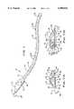
- FIG. 8is schematic view of a series of surgical retractor stays according to the first embodiment of the present invention in use.
- FIG. 9is a cross-sectional view along the line 9--9 in FIG. 8.
- FIG. 10is a cross-sectional view along the line 10--10 in FIG. 8.
- FIG. 11is a conventional spherical hub for a surgical retractor stay.
- FIGS. 12 through 16are views of hub embodiments for surgical retractor stays according to the present invention.
- FIG. 17is a surgical retractor stay according to a second embodiment of the present invention.
- FIG. 18is a side view of the surgical retractor stay according to the second embodiment of the present invention.
- FIG. 19is a surgical retractor stay according to a third embodiment of the present invention.
- FIG. 20is a surgical retractor stay according to a forth embodiment of the present invention.
- FIG. 21is a schematic view of surgical stays according to the first and second embodiments of the present invention in use.
- the stay 10includes a retention hook 12, a handle 14 and an elongated elastic member, or band 16.
- the band 16has a longitudinal body 18 having a series of hubs 20.
- a proximal end, or handle end 22, of the band 16is terminated by a retaining bulb 24 (FIGS. 7A and 7B).
- a distal end, or free end 25, of the band 16is located distal to the handle 14.
- the hook 12is preferably made from metal, such as stainless steel.
- the hook 12has a first end, or tissue engaging portion 26, extending from the handle 14.
- the tissue engaging portion 26is preferably curved, hook shaped, or otherwise bent to grasp tissue 28 surrounding an incision 30 and hold the incision 30 open.
- multiple stays 10can be used in concert with each other to hold the incision 30 open and thereby provide stable access to the incision 30.
- the hook 12has a second end 32 which is secured by the handle 14.
- the second end 32 of the hook 12is bent to form a securing loop 34.
- the handle 14has a first body member 36 and a second body member 38.
- the first body member 36 and the second body member 38are adapted to mate together to form the handle 14.
- the first body member 36 and the second body member 38are permanently fastened to one another, preferably with adhesive or thermal bonding, and cooperate to capture the second end 32 of the hook, as will be described hereinafter.
- the first body member 36is provided with a groove 40 at a first end 42 thereof.
- the first body member 36is also provided with an internal recess 44 for accepting the securing loop 34 of the hook 12.
- the groove 40securely surrounds the hook 12 as the hook 12 enters the handle 14.
- the groove 40forms a passage for the hook 12 to enter the handle 14 so that the securing loop 34 portion of the hook 12 can be received in the recess 44.
- the recess 44is in communication with the groove 40.
- the recess 44is shaped to accommodate the securing loop 34.
- the first body member 36has a boss 46 located in the recess 44 and extending through the securing loop 34 of the hook 12 so as to assist in retaining the hook 12 in the handle 14.
- the boss 46is located such that a portion of the hook 12 is trapped between the boss 46 and at least one sidewall 48 of the recess 44.
- the boss 46is dimensioned so that the second body member 38, which preferably has a flat interior side, flatly engages the boss 46 and the unrecessed portion of the first body member 36, thereby trapping the hook 12 in the handle 14.
- the first body member 36is preferably thicker than the second body member 38 in order to have enough room for the groove 40 and recess 44 in which the hook 12 is secured.
- a second end 50 of the handle 14is preferably provided with shoulders 52 for assisting in gripping the handle 14 portion of the stay 10.
- the shoulders 52project from the exterior side surfaces of the first body member 36 and the second body member 38. Shoulders 52 can optionally be provided at the first end 42 of the handle 14 as well.
- the second end 50 of the handle 14is provided with a channel 54 for receiving and retaining the retaining bulb 24 of the band 16.
- portions of the channel 54are formed in both the first body member 36 and the second body member 38.
- the channel 54 and retaining bulb 24have complimentary shapes such that the handle 14 securely traps the bulb 24 in the handle 14 to prevent separation of the handle 14 and band 16.
- the bulb 24preferably includes a planar face 56 which is in a generally perpendicular relationship to the longitudinal axis of the body 18 and faces toward the free end 25 of the band 16.
- the planer face 56forms an engagement surface which coacts with a complimentary surface 58 in the channel 54 to prevent the band 16 from being pulled from the handle 14.
- the channel 54 and bulb 24are semi-spherical.
- bulb 24 and channel 54can have other shapes so long as they have complementary engaging surfaces to prevent disengagement.
- the first body member 36 and the second body member 38fit securely around the retaining bulb 24 and body 18 of the band 16. This not only helps to keep the handle 14 and band 16 from disengaging, but also prevents blood and debris from entering the channel 54.
- the first body member 36 and the second body member 38can slightly compress the portion of the body 18 of the band 16 received in the channel 54 of the handle 14 so as to further prevent disengagement and entry of debris.
- the shoulders 52 at the second end 50 of the handle 14not only assist the surgeon or user grip the stay 10, but provides extra thickness to the handle 14 to accommodate the channel 54.
- Alternative methods of connecting the band 16 and the handle 14are contemplated. These methods include for example, increasing the hardness of the handle end 22 of the band 16 and/or fashioning a clipped type of engagement between the band 16 and the handle 14.
- FIG. 7Bshows the interior side of the first body member 36, the hook 12 and a portion of the band. For clarity, the second body member 38 has been removed.
- the first body member 36is provided with the groove 40, the recess 44 and the boss 46 for receiving and trapping the hook 12.
- the second end 50 of the handle 14is provided with a channel 54 to receive and retain the retaining bulb 24 of the band 16.
- the first body member 36is provided with a peg 120 located in the channel 54.
- the peg 120extends into a hole 122 defined by the bulb 24.
- the peg 120 and the hole 122are preferably arranged transverse to the longitudinal axis of the band 16.
- the corresponding shapes of the bulb 24 and channel 54are not as critical as in the first handle embodiment. This is because the peg 120 will assist in retaining the band 16.
- the bulb 24preferably has a more oval shape with flattened side surfaces 124.
- the shapegives the bulb 24 a trimmer size to better fit in the handle 14. Edges 126 of the bulb 24 are preferably provided with rounded corners. An intersection 128 between the bulb 24 and the body 18 of the band 16 is preferably molded with a fillet 130.
- the fillet 130serves to relieve stresses caused when the band 16 is placed under tension thereby helping to avoid tearing of the band at the intersection 128.
- the term filletis understood to means a rounded inside corner. More specifically, a fillet is a concavely curved section at the angle formed by the junction of two surfaces.
- the first body member 36 of the second handle embodimentis preferably provided with a perimeter notch 131 adapted to receive a perimeter projection provided on the second body member 38.
- the first body member 36is also preferably provided with receptacles 132 for receiving posts provided on the second body member 38.
- the second body member 38can also be provided with a receptacle for receiving the peg 120, depending on the length of the peg 120.
- both the first and second body members 36, 38can be provided with pegs which are received in the hole 122 or multiple holes 122 defined by the bulb 24.
- the second handle embodimentis preferably provided with shoulders 52 to assist in gripping the handle 14.
- the handle 14has a pair of body members 36, 38 which connect together and retain the band 16 and the hook 12.
- the band 16 and the hook 12are retained independently of one another. More specifically, the band 16 plays no role in retaining the hook 12 and the hook 12 plays no role in retaining the band 16.
- the band 16 and hook 12preferably do not contact each other.
- a frame 60is adapted to surround all or part of a surgical site 62 and act as a support for the stay 10, or series of stays 10, so that the stay(s) 10 can hold the incision 30 open. It is noted that frames of this type are well known in the art and do not form part of the present invention. If further information regarding surgical frames is desired, reference should be made to the surgical frame patents and applications identified in the Description of Related Art section of this specification. Accordingly, the frame 60 is only illustrated and described to the extend necessary to understand the present invention.
- the frame 60has a flange 64 having an upper surface 66 and a lower surface 68. The upper surface 66 and the lower surface 68 are generally planar.
- the frame 60is provided with notches 70 extending from the upper surface 66 to the lower surface 68.
- the notches 70are adapted to releasably receive the body 18 of the band 16.
- the notch 70is preferably sized about as large as the body 18 of the band 16, sometimes smaller. Should the notch 70 be sized smaller than the body 18 of the band 16, the frame 60 will slightly compress the body 18 as the body 18 is inserted into the notch 70.
- the stay 10is used by placing the tissue engaging portion 26 of the hook 12 on the tissue 28 to be retained and inserting the body 18 of the band 16 in one of the notches 70 of the frame 60.
- the stay 10is prevented from moving forward, or towards the surgical site 62, and from being pulled through the notch 70 by mechanical interference. More specifically, the hub 20 adjacent the frame 60 abuts a portion of the lower surface 68 of the frame 60 surrounding the notch 70 thereby preventing movement of the stay 10 except for stretching of the elastic band 16.
- the band 16is preferably solid and made from elastomeric material, such as silicone rubber.
- the band 16preferably has a durometer hardness of about 40 Shore A. As should be apparent, a higher hardness will increase the engagement properties between the hubs 20 and the frame 60. However, this will sacrifice the elastic qualities of the stay 10. This is not desirable since a relatively less elastic stay 10 will loose characteristics important to most surgeons, namely the ability of the hook 12 and handle 14 portions of the stay 10 to move with the tissue 28 being retained as the surgical site 62 shifts during the operation to minimize tearing of the tissue 28 being retracted. The elastic characteristics also allow the stay 10 to be removed from the tissue 28 and/or the frame 60, and allow the band 16 to conveniently bend as best illustrated in FIGS. 9 and 10.
- a plurality of hubs 20which are spaced apart along the length of the body 18.
- the hubs 20extend radially from the body 18.
- the entire band 16, including the hubs 20, the body 18 and the retaining bulb 24,is integrally molded in a single molding process.
- the band 16is liquid injection molded.
- Each hub 20is provided with a frame engagement surface 72 at an end of the hub 20 facing the surgical site 62.
- the frame engagement surface 72is an annular flat face disposed in a generally perpendicular relationship to the longitudinal axis of the body 18.
- Another way to describe the band 16is an alternating series of cylindrical body portions and larger cylindrical hub 20 portions.
- the hubs 20are provided with a broad, or planar, engagement surface 72 to contact the lower surface 68 of the flange 64 portion of the frame 60 surrounding the notch 70.
- the engagement surface 72is effective to distribute tension placed on the band away from the body 18 of the band 16 and thus away from the lower surface 68 area immediately adjacent the notch 70.
- the hub 200With spherical hubs 200 (FIG. 11), as taught by the prior art, the hub 200 initially makes a line contact with the frame 60 at a leading edge 202 of the hub 200 which circles the body 204 on an end of the hub 200 closest to the handle end 206. Consequently, tension is transferred from the hub 200 to the frame 60 immediately adjacent the body 204 which corresponds to an area on the frame 60 that is right against the notch 70. This transfer of force so close to the notch 70 allows the leading edge 202 of the spherical hub 200 to start entering the notch 70. Once partially entered into the notch 70, the spherical hub 200 compresses and squeezes through the notch 70.
- a merger plane 208 where the body 204 and the hub 200 interface to create the leading edge 202is shown by a broken line.
- Merger plane 208is perpendicular to the longitudinal axis of the body 204.
- a curved or arcuate surface 210 of the hub 200extends from the merger plane 208 away from the handle end 206 of the body 204. As more tension is placed on the body 204, the arcuate surface 210 is pulled towards the frame 60 and becomes the engagement surface of the hub, albeit an engagement surface that tends to pull through the notch 70.
- the surface 210is disposed further away from the handle end 206 than the merger plane 208 is from the handle end 206.
- the hub 20 of the present inventionhas an engagement surface 72 that is in face-to-face contact with the lower surface 68 of the frame 60.
- This engagementprovides a distributed area where any tension placed on the band 16 will be transferred to the frame 60.
- This distributed areais larger than, and therefore capable of absorbing greater amounts of tension than, the line-type contact made between the lower surface 68 of the frame 60 and a spherical hub 200 enabling the spherical hub 200 to leverage and compress its way through the notch 70.
- the band 16is placed under relatively less tension than the band 16 in FIG. 9. Therefore, the engagement surface 72 of the hub 20 will have a tendency to sit askew against the lower surface 68 of the frame 60 such that only a portion 74 of the engagement surface 72 is in engagement with the lower surface 68.
- the hub 20will also have a tendency to compress due tension placed on the elastomeric qualities of the band 16 resulting in the configuration illustrated. Nevertheless, the portion 74 of the engagement surface 72 that does contact the lower surface 68 is in a flat relationship with, and makes face-to-face contact with, the lower surface 68.
- the forces placed on the band 16are distributed over a broad area which is capable of absorbing greater amounts of tension than the contact area made between a spherical hub and the lower surface 68 of the frame 60.
- a side 75 of the hub 20is not in contact with the frame 60. Rather, only the portion 74 of the engagement surface 72 which is in contact with the lower surface 68 of the frame 60. This is a result of the elastomeric qualities of the band 16 and the flange 64 portion of the frame 60 being placed at an angle.
- the present inventionprovides a retractor stay 10 having the engagement qualities of a metal band and the elastic qualities of an elastomeric band.
- the body 18 and the hub 20merge with each other at an end of the hub 20 adjacent a merger plane 76, shown in FIG. 12 by a broken line.
- the merger plane 76is generally perpendicular to the longitudinal axis of the band 16.
- the engagement surface 72 of the hub 20is at least as close to the handle end 22 of the band 16 as merger plane 76 is to the handle end 22. Most preferably, the engagement surface 72 is coincident with the merger plane 76.
- the circular cross-sectional shape of the illustrated hub 20is exemplary.
- the present inventionis not to be limited to a stay 10 having the illustrated shapes. Other suitable shapes include, for example, oval and rectangular. In these alternative examples of cross-sectional shapes, the engagement surface 72 will not be annular. However, so long as the engagement surface 72 flatly mates against the frame 60, the hubs 20 will still be effective to prevent the hub 20 from pulling through the frame 60.
- the hub 20is provided with an engagement surface 72 that is not planar or flat but is still effective to distribute tension placed on the band away from the lower surface 68 area immediately adjacent the notch 70.
- the engagement surface 72is at least as close to the handle end 22 of the band as the merger plane 76 is to the handle end 22.
- Example shapesare a bowl-shaped engagement surface 72 and the illustrated concave engagement surface 72 where the merger plane 76 is tangent the engagement surface 72. Under tension, the concave shape may deform against the frame 60 to be relative planar, but the force applied to the band 16 will remain distributed away from the body 18 of the band 16 and away from the notch 70.
- the hub 20can be conical hubs 20 or semi-spherical, similar to the retaining bulb 24 illustrated in FIG. 7A, but with the face 56 side facing the surgical site 62 and serving as the engagement surface 72.
- the engagement surface 72is at least as close to the handle end 22 of the band 16 as the merger plane 76 is to the handle end 22.
- Illustrated in FIG. 14is a conical hub 20 having a planar engagement surface 72 coincident with the merger plane 76.
- This type of hub 20has the ability to be pulled through the frame 60 in one direction to add tension to the band 16 thereby further retracting the tissue 28, but will not inadvertently pull through the frame 60 towards the surgical site 62.
- the engagement surface 72is angled or beveled with respect to the longitudinal axis of the band 16 to match an angled flange 64 portion of the frame 60 (FIGS. 9 and 10).
- the engagement surface 72is no longer generally perpendicular to the longitudinal axis of the band 16, but the engagement surface 72 still flatly mates against the lower surface 68 of frame 60.
- the hub 20mates with the body 18 at a merger plane 76 such that a portion 78 of the engagement surface 72 is at least as close to the handle end 22 of the band 16 as the merger plane 76 is to the handle end 22.
- the merger plane 76is coincident with the engagement surface 72.
- the band 16is preferably molded with a fillet 140 at an intersection of the body 18 and the engagement surface 72.
- the fillet 140is a concavely curved section located at the junction of the surface forming the side of the body 18 and the generally planar engagement surface 72.
- the radius of the fillet 140is preferably about 0.010 inches.
- the fillet 140acts to locally reduce stress placed on the band 16 when it is placed under tension. Reducing the stress at the intersection of the body 18 and the hub 20 reduces the likelihood that the band 16 will break at this intersection.
- the fillet 140is disposed closer to the handle end 22 of the band 16 than the merger plane 76 and/or the engagement surface 72, the fillet is too small to have any significant engagement with the frame 60.
- the fillet 140will most likely enter the notch 70 when the band 16 is placed under tension.
- the engagement surface 72will still make face-to-face contact with the lower surface 68 of the frame 60.
- the engagement surface 72will provide a distributed area to transfer any tension placed on the band 16 to the frame 60.
- the fillet 140is too small with respect to the engagement surface 72 to allow the hub 20 to start to enter the notch 70, and compress and leverage its ways through the notch 70. This is why the merger plane 76 is considered to still be coincident with the engagement surface 72 in this hub embodiment rather than positioned at another point relative to the fillet 140.
- the hub 20is also preferably provided with a rounded corner 142 at the intersection of the engagement surface 72 and the side 75 of the hub 20.
- the radius of the rounded corner 142is preferably about 0.005 inches.
- the rounded corner 142is provided to impart a softer texture to the band 16 and also eases release of the band 16 from the mold.
- the strap 80provides a first band 82, a second band 84 and a broad body 86, such as a planar strip.
- the first band 82 and the second band 84 of the second embodimentare similar to the band 16 of the first embodiment and have a body 18, a series of hubs 20, a proximal end 22 and a free end 25.
- the broad body 86has a first end 88 and a second end 90.
- the broad body 86is disposed between and connected to the first band 82 and the second band 84.
- the first end 90is connected to the proximal end 22 of the first band 82 and the second end 90 is connected to the proximal end of the second band 84.
- the entire strap 80is preferably a unitary piece of elastomeric material such that the first band 82, the second band 84, and the broad body 86 are integrally connected and stretchable.
- Such a strap 80can be made of materials such as silicone rubber, PVC or polyurethane, or a combination thereof.
- the hardness (durometer) of the strap 80can be increased or decreased relative to the hardness of the first and second bands 82, 84.
- the broad body 86can be made of a different material than the first and second bands 82, 84.
- Example materialsare foam or a woven fabric. Preferably, the material is stretchable.
- Example connectorsinclude the bulb/channel arrangement used by the first embodiment between the band 16 and the handle 14, snaps, clips, stitching and the like.
- FIG. 21depicts a pair of straps 80 in use with a frame 60 and two stays 10 of the first embodiment during a surgical procedure on the palm or wrist of a hand.
- One of the straps 80is used to hold the patient's fingers down by resisting the fingers' tendency to curl by natural tension of the flextured tendons.
- the first band 82is held by a notch 70 on one side of the frame 60.
- the second band 84is held by another notch 70 on the opposite side of the frame.
- the broad body 86 portion of the strap 80lies on top of the patient's fingers to offer resistance against the fingers.
- the thumbalso has a tendency to curl during palm and wrist surgery.
- the other strap 80 illustrated in FIG. 21is used to hold back the patient's thumb.
- the first and second bands 82, 84are placed in separate notches 70 adjacent the thumb and the broad body 86 portion is wrapped around the thumb as illustrated to resist inward movement of the thumb.
- both bands 82, 84may be placed in the same notch 70, if the notch 70 is sized appropriately. Fingers can also be held away from one another by using the strap 80 in the same manner as illustrated for the thumb.
- a surgical retractor stay, or strap 92according to a third embodiment of the present invention is illustrated.
- the strap 82provides a band 94 similar to that of the band 16 of the first embodiment and a broad body 86 similar to the broad body 86 of the second embodiment.
- the proximal end 22 of the band 94is connected to the first end 88 of the broad body 86. Since the broad body 86 is made of flexible material, it is adapted to bend so as to form a loop when the first end 88 is fastened to the second end 90.
- the fasteningcan be by any mechanical fastening means.
- the fastening meanscan be preattached to the strap 92 or attached to the strap 92 as needed.
- fastening meansare snaps 96 provided at end 88, 90 of the broad body 86, that are adapted to mate together.
- Other fastening means examplesinclude hook and loop type fasteners, clips, crimps, threaded devices, buckles, buttons and the like.
- the ends 88, 90can also be fastened by fusing them together or with adhesive.
- the strap 92can alternatively be provided with a fastening means including a hole and a serrated end adapted to fit through the hole without pulling back through, similar to the arrangement of a cable tie or a garbage bag tie.
- a surgical retractor stay, or strap 98according to a forth embodiment of the present invention is illustrated.
- the strap 98is provided with a band 94 similar to the band 16 of the first embodiment.
- the strap 98is also provided with a broad body 86 similar to broad body 86 of the second and third embodiments, but both the first end 88 and the second end 90 are permanently connected to the proximate end 22 of the band 94.
- the connection among the ends 20, 88, 90is preferably made during the molding process.
- the strap 92 of the third embodimentcan be manufactured and then the second end 90 can be fused or secured with adhesive to the area where the proximal end 22 and the first end 88 connect.
Landscapes
- Health & Medical Sciences (AREA)
- Life Sciences & Earth Sciences (AREA)
- Surgery (AREA)
- Heart & Thoracic Surgery (AREA)
- Engineering & Computer Science (AREA)
- Biomedical Technology (AREA)
- Nuclear Medicine, Radiotherapy & Molecular Imaging (AREA)
- Medical Informatics (AREA)
- Molecular Biology (AREA)
- Animal Behavior & Ethology (AREA)
- General Health & Medical Sciences (AREA)
- Public Health (AREA)
- Veterinary Medicine (AREA)
- Surgical Instruments (AREA)
Abstract
Description
Claims (21)
Priority Applications (8)
| Application Number | Priority Date | Filing Date | Title |
|---|---|---|---|
| US09/313,143US6090043A (en) | 1999-05-17 | 1999-05-17 | Tissue retractor retention band |
| JP2000617786AJP4180245B2 (en) | 1999-05-17 | 2000-04-06 | Tissue retractor holding band |
| AT00920180TATE432655T1 (en) | 1999-05-17 | 2000-04-06 | BAND FOR HOLDING A TISSUE RETRACTOR |
| EP00920180AEP1185195B1 (en) | 1999-05-17 | 2000-04-06 | Tissue retractor retention band |
| PCT/US2000/009134WO2000069326A1 (en) | 1999-05-17 | 2000-04-06 | Tissue retractor retention band |
| DE60042324TDE60042324D1 (en) | 1999-05-17 | 2000-04-06 | BAND FOR HOLDING A FABRIC TRACTOR |
| CA002363392ACA2363392C (en) | 1999-05-17 | 2001-11-16 | Tissue retractor retention band |
| JP2008061042AJP4841580B2 (en) | 1999-05-17 | 2008-03-11 | Tissue retractor holding band |
Applications Claiming Priority (2)
| Application Number | Priority Date | Filing Date | Title |
|---|---|---|---|
| US09/313,143US6090043A (en) | 1999-05-17 | 1999-05-17 | Tissue retractor retention band |
| CA002363392ACA2363392C (en) | 1999-05-17 | 2001-11-16 | Tissue retractor retention band |
Publications (1)
| Publication Number | Publication Date |
|---|---|
| US6090043Atrue US6090043A (en) | 2000-07-18 |
Family
ID=32070504
Family Applications (1)
| Application Number | Title | Priority Date | Filing Date |
|---|---|---|---|
| US09/313,143Expired - LifetimeUS6090043A (en) | 1999-05-17 | 1999-05-17 | Tissue retractor retention band |
Country Status (5)
| Country | Link |
|---|---|
| US (1) | US6090043A (en) |
| EP (1) | EP1185195B1 (en) |
| JP (1) | JP4180245B2 (en) |
| CA (1) | CA2363392C (en) |
| WO (1) | WO2000069326A1 (en) |
Cited By (74)
| Publication number | Priority date | Publication date | Assignee | Title |
|---|---|---|---|---|
| USD449688S1 (en) | 2000-08-23 | 2001-10-23 | Applied Medical Technology, Inc. | Surgical support band |
| US6409731B1 (en) | 2001-07-30 | 2002-06-25 | Global Orthopaedic Solutions, L.L.C. | Bone leveler apparatus |
| US20040186356A1 (en)* | 2001-08-08 | 2004-09-23 | O'malley Michael T. | Surgical retractor and tissue stabilization device |
| US20050165280A1 (en)* | 2002-05-09 | 2005-07-28 | Russell Heinrich | Organ retractor and method of using the same |
| WO2005070304A1 (en)* | 2004-01-08 | 2005-08-04 | Ams Research Corporation | Surgical retractor having suture control features |
| US6932765B2 (en) | 2001-10-26 | 2005-08-23 | Minnesota Scientific, Inc. | Apparatus for retaining otherwise hand-held retractors |
| US20050240083A1 (en)* | 2002-05-09 | 2005-10-27 | Orban Joseph Iii | Endoscopic organ retractor and method of using the same |
| US20050241647A1 (en)* | 2002-06-05 | 2005-11-03 | Applied Medical Resources Corporation | Wound retractor |
| US20050272982A1 (en)* | 2001-10-26 | 2005-12-08 | Minnesota Scientific, Inc. | Apparatus for retaining otherwise hand-held retractors and method of use |
| US20060052670A1 (en)* | 2002-10-04 | 2006-03-09 | Stearns Ralph A | Endoscopic retractor |
| US7022069B1 (en) | 2001-07-30 | 2006-04-04 | Si-1, Inc. | Circumferential retractor apparatus with locking slots |
| US20060272979A1 (en)* | 2005-06-07 | 2006-12-07 | Lubbers Lawrence M | Surgical Tray |
| US20070156023A1 (en)* | 2006-01-05 | 2007-07-05 | Depuy Spine, Inc. | Non-rigid surgical retractor |
| US20070161867A1 (en)* | 2006-01-11 | 2007-07-12 | Lone Star Medical Products, Inc. | Retractor blade and bridge system |
| US20070250116A1 (en)* | 2006-04-25 | 2007-10-25 | Board Of Regents, The University Of Texas System | Tissue Approximator and Retractor Assistive Device |
| US20080055512A1 (en)* | 2006-08-31 | 2008-03-06 | Tae Hyuck Kim | Liquid crystal display |
| EP1441648A4 (en)* | 2001-10-20 | 2008-04-09 | Applied Med Resources | Wound retraction apparatus and method |
| US20080156333A1 (en)* | 2006-12-31 | 2008-07-03 | David Wolf Galpern | Radio lucent restraining device |
| WO2008045940A3 (en)* | 2006-10-10 | 2008-09-12 | Adrian Edward Park | Adjustable line and net retractors |
| US7473221B2 (en) | 2000-10-19 | 2009-01-06 | Applied Medical Resources Corporation | Surgical access apparatus and method |
| US20090018400A1 (en)* | 2003-12-18 | 2009-01-15 | Depuy Spine, Inc. | Surgical retractor systems and illuminated cannulae |
| US20100030269A1 (en)* | 2006-09-07 | 2010-02-04 | Jean Taylor | Interspinous spinal prosthesis |
| US7704207B2 (en) | 2005-10-14 | 2010-04-27 | Applied Medical Resources Corporation | Circular surgical retractor |
| US20100121456A1 (en)* | 2002-09-10 | 2010-05-13 | Kyphon Sarl | Posterior vertebral support assembly |
| US20100152779A1 (en)* | 2006-11-15 | 2010-06-17 | Warsaw Orthopedic, Inc. | Inter-transverse process spacer device and method for use in correcting a spinal deformity |
| US7758501B2 (en) | 2006-01-04 | 2010-07-20 | Depuy Spine, Inc. | Surgical reactors and methods of minimally invasive surgery |
| US20100185241A1 (en)* | 2009-01-16 | 2010-07-22 | Malandain Hugues F | Adjustable surgical cables and methods for treating spinal stenosis |
| US7909853B2 (en) | 2004-09-23 | 2011-03-22 | Kyphon Sarl | Interspinous process implant including a binder and method of implantation |
| US7918792B2 (en) | 2006-01-04 | 2011-04-05 | Depuy Spine, Inc. | Surgical retractor for use with minimally invasive spinal stabilization systems and methods of minimally invasive surgery |
| US7951076B2 (en) | 2003-02-25 | 2011-05-31 | Applied Medical Resources Corporation | Surgical access system |
| US7981031B2 (en) | 2006-01-04 | 2011-07-19 | Depuy Spine, Inc. | Surgical access devices and methods of minimally invasive surgery |
| US8012209B2 (en) | 2004-09-23 | 2011-09-06 | Kyphon Sarl | Interspinous process implant including a binder, binder aligner and method of implantation |
| US8034079B2 (en) | 2005-04-12 | 2011-10-11 | Warsaw Orthopedic, Inc. | Implants and methods for posterior dynamic stabilization of a spinal motion segment |
| US8048117B2 (en) | 2003-05-22 | 2011-11-01 | Kyphon Sarl | Interspinous process implant and method of implantation |
| WO2011149466A1 (en)* | 2010-05-27 | 2011-12-01 | Picha George J | Tissue retractor stay |
| US20110295075A1 (en)* | 2010-05-27 | 2011-12-01 | Picha George J | Tissue retractor stay |
| US8105357B2 (en)* | 2006-04-28 | 2012-01-31 | Warsaw Orthopedic, Inc. | Interspinous process brace |
| US8109873B2 (en) | 2007-05-11 | 2012-02-07 | Applied Medical Resources Corporation | Surgical retractor with gel pad |
| US8157835B2 (en) | 2001-08-14 | 2012-04-17 | Applied Medical Resouces Corporation | Access sealing apparatus and method |
| US8187177B2 (en) | 2003-09-17 | 2012-05-29 | Applied Medical Resources Corporation | Surgical instrument access device |
| FR2968534A1 (en)* | 2010-12-10 | 2012-06-15 | Xavier Renard | Device for fettering part i.e. finger, of living being for production of lead hand, has set of bulges, where overall section of set of bulges is provided in plane that is perpendicular to longitudinal axis of link having specific value |
| US8226552B2 (en) | 2007-05-11 | 2012-07-24 | Applied Medical Resources Corporation | Surgical retractor |
| US8262568B2 (en) | 2008-10-13 | 2012-09-11 | Applied Medical Resources Corporation | Single port access system |
| US8343047B2 (en) | 2008-01-22 | 2013-01-01 | Applied Medical Resources Corporation | Surgical instrument access device |
| CN102940511A (en)* | 2012-11-02 | 2013-02-27 | 陈健 | Abdominal operation incision retracting device |
| US8388526B2 (en) | 2001-10-20 | 2013-03-05 | Applied Medical Resources Corporation | Wound retraction apparatus and method |
| US20130137934A1 (en)* | 2011-11-30 | 2013-05-30 | Abeon Medical Corporation | Tissue retractor stay |
| US20130261401A1 (en)* | 2012-03-30 | 2013-10-03 | Depuy Spine, Inc. | Methods and Devices for Tissue Retraction |
| US8568455B2 (en) | 1997-01-02 | 2013-10-29 | Warsaw Orthopedic, Inc. | Spine distraction implant and method |
| US8703034B2 (en) | 2001-08-14 | 2014-04-22 | Applied Medical Resources Corporation | Method of making a tack-free gel |
| US8758236B2 (en) | 2011-05-10 | 2014-06-24 | Applied Medical Resources Corporation | Wound retractor |
| US9084594B2 (en) | 2012-01-10 | 2015-07-21 | The Board Of Trustees Of The Lealand Stanford Junior University | Methods for the prevention of surgical site infections |
| USRE45827E1 (en)* | 2010-12-13 | 2015-12-29 | Jianmin Qian | Self-service surgical retractor |
| US9289200B2 (en) | 2010-10-01 | 2016-03-22 | Applied Medical Resources Corporation | Natural orifice surgery system |
| US9289115B2 (en) | 2010-10-01 | 2016-03-22 | Applied Medical Resources Corporation | Natural orifice surgery system |
| US9642608B2 (en) | 2014-07-18 | 2017-05-09 | Applied Medical Resources Corporation | Gels having permanent tack free coatings and method of manufacture |
| US9717522B2 (en) | 2009-08-31 | 2017-08-01 | Applied Medical Resources Corporation | Multi-functional surgical access system |
| GB2553313A (en)* | 2016-08-31 | 2018-03-07 | Bailey Instruments Ltd | Surgical retraction apparatus |
| WO2018046916A1 (en)* | 2016-09-06 | 2018-03-15 | Sheffmed Trade Services Limited | Surgical retractor |
| US9949730B2 (en) | 2014-11-25 | 2018-04-24 | Applied Medical Resources Corporation | Circumferential wound retraction with support and guidance structures |
| US9951904B2 (en) | 2015-03-24 | 2018-04-24 | Stryker Corporation | Rotatable seat clamps for rail clamp |
| US9974564B2 (en) | 2013-03-14 | 2018-05-22 | Prescient Surgical, Inc. | Methods and devices for the prevention of incisional surgical site infections |
| US10172641B2 (en) | 2014-08-15 | 2019-01-08 | Applied Medical Resources Corporation | Natural orifice surgery system |
| US10327751B2 (en) | 2013-03-20 | 2019-06-25 | Prescient Surgical, Inc. | Methods and apparatus for reducing the risk of surgical site infections |
| US10368908B2 (en) | 2015-09-15 | 2019-08-06 | Applied Medical Resources Corporation | Surgical robotic access system |
| US10478364B2 (en) | 2014-03-10 | 2019-11-19 | Stryker Corporation | Limb positioning system |
| US10575840B2 (en) | 2015-10-07 | 2020-03-03 | Applied Medical Resources Corporation | Wound retractor with multi-segment outer ring |
| WO2020060730A1 (en)* | 2018-09-18 | 2020-03-26 | Maruho Medical, Inc. | Tissue care device and method of use |
| US10674896B2 (en) | 2016-09-12 | 2020-06-09 | Applied Medical Resources Corporation | Surgical robotic access system for irregularly shaped robotic actuators and associated robotic surgical instruments |
| US11471142B2 (en) | 2013-03-15 | 2022-10-18 | Applied Medical Resources Corporation | Mechanical gel surgical access device |
| US11596439B2 (en) | 2017-11-07 | 2023-03-07 | Prescient Surgical, Inc. | Methods and apparatus for prevention of surgical site infection |
| US20240252160A1 (en)* | 2019-05-16 | 2024-08-01 | Boston Scientific Scimed, Inc. | Tissue traction bands and methods for tissue traction |
| GB2635283A (en)* | 2024-07-01 | 2025-05-07 | Mosaic Surgical Ltd | Frame |
| GB2637263A (en)* | 2024-07-01 | 2025-07-16 | Mosaic Surgical Ltd | Securing device |
Citations (28)
| Publication number | Priority date | Publication date | Assignee | Title |
|---|---|---|---|---|
| US32201A (en)* | 1861-04-30 | John Neumann | Faucet | |
| US2384304A (en)* | 1944-08-18 | 1945-09-04 | Helfrick Joseph Rembrandt | Anal retractor |
| US2659904A (en)* | 1949-05-05 | 1953-11-24 | Mcginnis Walter | Crib shortening, cover-holding device, and baby anchor |
| US2845925A (en)* | 1953-11-24 | 1958-08-05 | Jayle Gaetan Jean | Automatic eyelids eyeball fixing device for a surgical intervention |
| US3038468A (en)* | 1960-11-15 | 1962-06-12 | Randal R Raeuchle | Surgical retractor |
| US3070088A (en)* | 1961-02-02 | 1962-12-25 | Brahos Nicholas George | Surgical retractor device |
| US3515129A (en)* | 1967-12-29 | 1970-06-02 | Andrew Truhan | Surgical retractor and retainer device for sutures |
| US3522800A (en)* | 1966-07-19 | 1970-08-04 | Arthur J Lesser | Disposable wound retractor and drape and method of using same |
| US3542015A (en)* | 1968-03-25 | 1970-11-24 | Shirley A Steinman | Surgical retractor |
| US3762401A (en)* | 1972-01-05 | 1973-10-02 | J Tupper | Surgical retractor |
| US3823709A (en)* | 1973-04-27 | 1974-07-16 | Guire G Mc | Table supported surgical retractor and pelvic support |
| US3857386A (en)* | 1973-08-17 | 1974-12-31 | T Ashbell | Surgical device for holding and retracting skin or bone |
| US3882855A (en)* | 1973-11-12 | 1975-05-13 | Heyer Schulte Corp | Retractor for soft tissue for example brain tissue |
| US4274398A (en)* | 1979-05-14 | 1981-06-23 | Scott Jr Frank B | Surgical retractor utilizing elastic tubes frictionally held in spaced notches |
| US4430991A (en)* | 1981-11-05 | 1984-02-14 | Humboldt Products Corp. | Surgical retractor stay device and tube connector |
| US4434791A (en)* | 1982-03-15 | 1984-03-06 | Humboldt Products Corp. | Surgical retractor array system |
| DE3234875A1 (en)* | 1982-09-21 | 1984-03-22 | S & T Marketing AG, 8212 Neuhausen am Rheinfall | Device for preparing an operating area in surgery, especially in microsurgery |
| USRE32201E (en) | 1981-08-12 | 1986-07-08 | International Business Machines Corporation | Apparatus and method for reading and writing text characters in a graphics display |
| US4610243A (en)* | 1985-05-06 | 1986-09-09 | Charles D. Ray, Ltd. | Malleable force-fulcrum retractor |
| US5174279A (en)* | 1991-03-06 | 1992-12-29 | Duke University Medical Center | Iris retractor for use in operations on the eye of a living creature |
| US5514076A (en)* | 1994-01-27 | 1996-05-07 | Flexmedics Corporation | Surgical retractor |
| US5638584A (en)* | 1996-04-08 | 1997-06-17 | De Anfrasio; Antoine | Attachment and cable fastening device |
| US5709646A (en)* | 1994-09-23 | 1998-01-20 | Lange; Nancy Erin | Surgical retractor covers |
| US5769783A (en)* | 1996-06-27 | 1998-06-23 | Lone Star Medical Products, Inc. | Surgical retractor stay apparatus |
| US5785649A (en)* | 1997-03-31 | 1998-07-28 | Lone Star Medical Products,Inc. | Surgical retractor stay apparatus |
| US5899853A (en)* | 1998-05-11 | 1999-05-04 | Lone Star Medical Products, Inc. | Double grip surgical retractor stay |
| US5964697A (en)* | 1996-04-22 | 1999-10-12 | Lone Star Medical Products, Inc. | Surgical retractor stay apparatus |
| US5964698A (en)* | 1999-01-20 | 1999-10-12 | Lone Star Medical Products, Inc. | Sliding hook assembly for use with a surgical retractor stay apparatus and methods for use |
Family Cites Families (2)
| Publication number | Priority date | Publication date | Assignee | Title |
|---|---|---|---|---|
| US4069825A (en)* | 1976-01-28 | 1978-01-24 | Taichiro Akiyama | Surgical thread and cutting apparatus for the same |
| GB9111972D0 (en)* | 1991-06-04 | 1991-07-24 | Clinical Product Dev Ltd | Medical/surgical devices |
- 1999
- 1999-05-17USUS09/313,143patent/US6090043A/ennot_activeExpired - Lifetime
- 2000
- 2000-04-06EPEP00920180Apatent/EP1185195B1/ennot_activeExpired - Lifetime
- 2000-04-06WOPCT/US2000/009134patent/WO2000069326A1/enactiveApplication Filing
- 2000-04-06JPJP2000617786Apatent/JP4180245B2/ennot_activeExpired - Fee Related
- 2001
- 2001-11-16CACA002363392Apatent/CA2363392C/ennot_activeExpired - Lifetime
Patent Citations (29)
| Publication number | Priority date | Publication date | Assignee | Title |
|---|---|---|---|---|
| US32201A (en)* | 1861-04-30 | John Neumann | Faucet | |
| US2384304A (en)* | 1944-08-18 | 1945-09-04 | Helfrick Joseph Rembrandt | Anal retractor |
| US2659904A (en)* | 1949-05-05 | 1953-11-24 | Mcginnis Walter | Crib shortening, cover-holding device, and baby anchor |
| US2845925A (en)* | 1953-11-24 | 1958-08-05 | Jayle Gaetan Jean | Automatic eyelids eyeball fixing device for a surgical intervention |
| US3038468A (en)* | 1960-11-15 | 1962-06-12 | Randal R Raeuchle | Surgical retractor |
| US3070088A (en)* | 1961-02-02 | 1962-12-25 | Brahos Nicholas George | Surgical retractor device |
| US3522800A (en)* | 1966-07-19 | 1970-08-04 | Arthur J Lesser | Disposable wound retractor and drape and method of using same |
| US3515129A (en)* | 1967-12-29 | 1970-06-02 | Andrew Truhan | Surgical retractor and retainer device for sutures |
| US3542015A (en)* | 1968-03-25 | 1970-11-24 | Shirley A Steinman | Surgical retractor |
| US3762401A (en)* | 1972-01-05 | 1973-10-02 | J Tupper | Surgical retractor |
| US3823709A (en)* | 1973-04-27 | 1974-07-16 | Guire G Mc | Table supported surgical retractor and pelvic support |
| US3857386A (en)* | 1973-08-17 | 1974-12-31 | T Ashbell | Surgical device for holding and retracting skin or bone |
| US3882855A (en)* | 1973-11-12 | 1975-05-13 | Heyer Schulte Corp | Retractor for soft tissue for example brain tissue |
| US4274398A (en)* | 1979-05-14 | 1981-06-23 | Scott Jr Frank B | Surgical retractor utilizing elastic tubes frictionally held in spaced notches |
| USRE32201E (en) | 1981-08-12 | 1986-07-08 | International Business Machines Corporation | Apparatus and method for reading and writing text characters in a graphics display |
| USRE32201F1 (en) | 1981-08-12 | 1989-08-01 | Ibm | Apparatus and method for reading and writing text characters in a graphics display |
| US4430991A (en)* | 1981-11-05 | 1984-02-14 | Humboldt Products Corp. | Surgical retractor stay device and tube connector |
| US4434791A (en)* | 1982-03-15 | 1984-03-06 | Humboldt Products Corp. | Surgical retractor array system |
| DE3234875A1 (en)* | 1982-09-21 | 1984-03-22 | S & T Marketing AG, 8212 Neuhausen am Rheinfall | Device for preparing an operating area in surgery, especially in microsurgery |
| US4610243A (en)* | 1985-05-06 | 1986-09-09 | Charles D. Ray, Ltd. | Malleable force-fulcrum retractor |
| US5174279A (en)* | 1991-03-06 | 1992-12-29 | Duke University Medical Center | Iris retractor for use in operations on the eye of a living creature |
| US5514076A (en)* | 1994-01-27 | 1996-05-07 | Flexmedics Corporation | Surgical retractor |
| US5709646A (en)* | 1994-09-23 | 1998-01-20 | Lange; Nancy Erin | Surgical retractor covers |
| US5638584A (en)* | 1996-04-08 | 1997-06-17 | De Anfrasio; Antoine | Attachment and cable fastening device |
| US5964697A (en)* | 1996-04-22 | 1999-10-12 | Lone Star Medical Products, Inc. | Surgical retractor stay apparatus |
| US5769783A (en)* | 1996-06-27 | 1998-06-23 | Lone Star Medical Products, Inc. | Surgical retractor stay apparatus |
| US5785649A (en)* | 1997-03-31 | 1998-07-28 | Lone Star Medical Products,Inc. | Surgical retractor stay apparatus |
| US5899853A (en)* | 1998-05-11 | 1999-05-04 | Lone Star Medical Products, Inc. | Double grip surgical retractor stay |
| US5964698A (en)* | 1999-01-20 | 1999-10-12 | Lone Star Medical Products, Inc. | Sliding hook assembly for use with a surgical retractor stay apparatus and methods for use |
Non-Patent Citations (5)
| Title |
|---|
| "Tupper's Universal Handholder and Retractor Set", Accurate Surgical & Scientific Instruments Corporation, p. 39, (undated). |
| A. Kh. Izmailov and B.L. Elyashevich, "Universal Retractor for Cavity Surgery", Jul. 10, 1973, p. 320. |
| A. Kh. Izmailov and B.L. Elyashevich, Universal Retractor for Cavity Surgery , Jul. 10, 1973, p. 320.* |
| Tupper s Universal Handholder and Retractor Set , Accurate Surgical & Scientific Instruments Corporation, p. 39, (undated).* |
| Two and Four FingerStay, Lone Star Medical Products, Inc. (undated).* |
Cited By (159)
| Publication number | Priority date | Publication date | Assignee | Title |
|---|---|---|---|---|
| US8672974B2 (en) | 1997-01-02 | 2014-03-18 | Warsaw Orthopedic, Inc. | Spine distraction implant and method |
| US8568455B2 (en) | 1997-01-02 | 2013-10-29 | Warsaw Orthopedic, Inc. | Spine distraction implant and method |
| USD449688S1 (en) | 2000-08-23 | 2001-10-23 | Applied Medical Technology, Inc. | Surgical support band |
| US8911366B2 (en) | 2000-10-19 | 2014-12-16 | Applied Medical Resources Corporation | Surgical access apparatus and method |
| US8016755B2 (en) | 2000-10-19 | 2011-09-13 | Applied Medical Resources Corporation | Surgical access apparatus and method |
| US8496581B2 (en) | 2000-10-19 | 2013-07-30 | Applied Medical Resources Corporation | Surgical access apparatus and method |
| US7473221B2 (en) | 2000-10-19 | 2009-01-06 | Applied Medical Resources Corporation | Surgical access apparatus and method |
| US8070676B2 (en) | 2000-10-19 | 2011-12-06 | Applied Medical Resources Corporation | Surgical access apparatus and method |
| US8105234B2 (en) | 2000-10-19 | 2012-01-31 | Applied Medical Resources Corporation | Surgical access apparatus and method |
| US8672839B2 (en) | 2000-10-19 | 2014-03-18 | Applied Medical Resource Corporation | Surgical access apparatus and method |
| US7022069B1 (en) | 2001-07-30 | 2006-04-04 | Si-1, Inc. | Circumferential retractor apparatus with locking slots |
| US6409731B1 (en) | 2001-07-30 | 2002-06-25 | Global Orthopaedic Solutions, L.L.C. | Bone leveler apparatus |
| US20040186356A1 (en)* | 2001-08-08 | 2004-09-23 | O'malley Michael T. | Surgical retractor and tissue stabilization device |
| US9669153B2 (en) | 2001-08-14 | 2017-06-06 | Applied Medical Resources Corporation | Method of manufacturing a tack-free gel for a surgical device |
| US8870904B2 (en) | 2001-08-14 | 2014-10-28 | Applied Medical Resources Corporation | Access sealing apparatus and method |
| US8157835B2 (en) | 2001-08-14 | 2012-04-17 | Applied Medical Resouces Corporation | Access sealing apparatus and method |
| US9878140B2 (en) | 2001-08-14 | 2018-01-30 | Applied Medical Resources Corporation | Access sealing apparatus and method |
| US8703034B2 (en) | 2001-08-14 | 2014-04-22 | Applied Medical Resources Corporation | Method of making a tack-free gel |
| EP2289424A1 (en)* | 2001-10-20 | 2011-03-02 | Applied Medical Resources Corporation | Wound retraction apparatus |
| US8388526B2 (en) | 2001-10-20 | 2013-03-05 | Applied Medical Resources Corporation | Wound retraction apparatus and method |
| EP1441648A4 (en)* | 2001-10-20 | 2008-04-09 | Applied Med Resources | Wound retraction apparatus and method |
| US20050187435A1 (en)* | 2001-10-26 | 2005-08-25 | Minnesota Scientific, Inc. | Apparatus for retaining otherwise hand-held retractors |
| US7309312B2 (en) | 2001-10-26 | 2007-12-18 | Minnesota Scientific, Inc. | Apparatus for retaining otherwise hand-held retractors and method of use |
| US6932765B2 (en) | 2001-10-26 | 2005-08-23 | Minnesota Scientific, Inc. | Apparatus for retaining otherwise hand-held retractors |
| US20050272982A1 (en)* | 2001-10-26 | 2005-12-08 | Minnesota Scientific, Inc. | Apparatus for retaining otherwise hand-held retractors and method of use |
| US7311661B2 (en) | 2002-05-09 | 2007-12-25 | Tyco Healthcare Group Lp | Organ retractor and method of using the same |
| US20050240083A1 (en)* | 2002-05-09 | 2005-10-27 | Orban Joseph Iii | Endoscopic organ retractor and method of using the same |
| US7445598B2 (en) | 2002-05-09 | 2008-11-04 | Tyco Healthcare Group Lp | Endoscopic organ retractor and method of using the same |
| US20050165280A1 (en)* | 2002-05-09 | 2005-07-28 | Russell Heinrich | Organ retractor and method of using the same |
| US10507017B2 (en) | 2002-06-05 | 2019-12-17 | Applied Medical Resources Corporation | Wound retractor |
| US20050241647A1 (en)* | 2002-06-05 | 2005-11-03 | Applied Medical Resources Corporation | Wound retractor |
| US8235054B2 (en) | 2002-06-05 | 2012-08-07 | Applied Medical Resources Corporation | Wound retractor |
| US9561024B2 (en) | 2002-06-05 | 2017-02-07 | Applied Medical Resources Corporation | Wound retractor |
| US7650887B2 (en) | 2002-06-05 | 2010-01-26 | Applied Medical Resources Corporation | Wound retractor |
| US7913697B2 (en) | 2002-06-05 | 2011-03-29 | Applied Medical Resources Corporation | Wound retractor |
| US8973583B2 (en) | 2002-06-05 | 2015-03-10 | Applied Medical Resources Corporation | Wound retractor |
| US20100121456A1 (en)* | 2002-09-10 | 2010-05-13 | Kyphon Sarl | Posterior vertebral support assembly |
| US8043336B2 (en) | 2002-09-10 | 2011-10-25 | Warsaw Orthopedic, Inc. | Posterior vertebral support assembly |
| US20060052670A1 (en)* | 2002-10-04 | 2006-03-09 | Stearns Ralph A | Endoscopic retractor |
| US7951076B2 (en) | 2003-02-25 | 2011-05-31 | Applied Medical Resources Corporation | Surgical access system |
| US9295459B2 (en) | 2003-02-25 | 2016-03-29 | Applied Medical Resources Corporation | Surgical access system |
| US8932214B2 (en) | 2003-02-25 | 2015-01-13 | Applied Medical Resources Corporation | Surgical access system |
| US8048117B2 (en) | 2003-05-22 | 2011-11-01 | Kyphon Sarl | Interspinous process implant and method of implantation |
| US8357086B2 (en) | 2003-09-17 | 2013-01-22 | Applied Medical Resources Corporation | Surgical instrument access device |
| US8187177B2 (en) | 2003-09-17 | 2012-05-29 | Applied Medical Resources Corporation | Surgical instrument access device |
| US8622897B2 (en) | 2003-12-18 | 2014-01-07 | DePuy Synthes Products, LLC | Surgical methods and surgical kits |
| US10869657B2 (en) | 2003-12-18 | 2020-12-22 | DePuy Synthes Products, Inc. | Surgical retractor systems and illuminated cannulae |
| US20090018400A1 (en)* | 2003-12-18 | 2009-01-15 | Depuy Spine, Inc. | Surgical retractor systems and illuminated cannulae |
| US8602984B2 (en) | 2003-12-18 | 2013-12-10 | DePuy Synthes Products, LLC | Surgical retractor systems and illuminated cannulae |
| US8038611B2 (en) | 2003-12-18 | 2011-10-18 | Depuy Spine, Inc. | Surgical methods and surgical kits |
| WO2005070304A1 (en)* | 2004-01-08 | 2005-08-04 | Ams Research Corporation | Surgical retractor having suture control features |
| WO2005070303A1 (en)* | 2004-01-08 | 2005-08-04 | Ams Research Corporation | Surgical retractor with intermediate support members |
| US20050171405A1 (en)* | 2004-01-08 | 2005-08-04 | Rowland Randall P. | Surgical retractor with intermediate support members |
| US8012209B2 (en) | 2004-09-23 | 2011-09-06 | Kyphon Sarl | Interspinous process implant including a binder, binder aligner and method of implantation |
| US7909853B2 (en) | 2004-09-23 | 2011-03-22 | Kyphon Sarl | Interspinous process implant including a binder and method of implantation |
| WO2006076127A1 (en)* | 2005-01-12 | 2006-07-20 | The Levahn Intellectual Property Holding Company | Apparatus for retaining otherwise hand-held retractors |
| US8034079B2 (en) | 2005-04-12 | 2011-10-11 | Warsaw Orthopedic, Inc. | Implants and methods for posterior dynamic stabilization of a spinal motion segment |
| US20060272979A1 (en)* | 2005-06-07 | 2006-12-07 | Lubbers Lawrence M | Surgical Tray |
| US8647265B2 (en) | 2005-10-14 | 2014-02-11 | Applied Medical Resources Corporation | Hand access laparoscopic device |
| US7815567B2 (en) | 2005-10-14 | 2010-10-19 | Applied Medical Resources, Corporation | Split hoop wound retractor |
| US7909760B2 (en) | 2005-10-14 | 2011-03-22 | Applied Medical Resources Corporation | Split hoop wound retractor with gel pad |
| US8414487B2 (en) | 2005-10-14 | 2013-04-09 | Applied Medical Resources Corporation | Circular surgical retractor |
| US9017254B2 (en) | 2005-10-14 | 2015-04-28 | Applied Medical Resources Corporation | Hand access laparoscopic device |
| US9101354B2 (en) | 2005-10-14 | 2015-08-11 | Applied Medical Resources Corporation | Wound retractor with gel cap |
| US8267858B2 (en) | 2005-10-14 | 2012-09-18 | Applied Medical Resources Corporation | Wound retractor with gel cap |
| US8308639B2 (en) | 2005-10-14 | 2012-11-13 | Applied Medical Resources Corporation | Split hoop wound retractor with gel pad |
| US8313431B2 (en) | 2005-10-14 | 2012-11-20 | Applied Medical Resources Corporation | Split hoop wound retractor |
| US9649102B2 (en) | 2005-10-14 | 2017-05-16 | Applied Medical Resources Corporation | Wound retractor with split hoops |
| US7892172B2 (en) | 2005-10-14 | 2011-02-22 | Applied Medical Resources Corporation | Circular surgical retractor |
| US7704207B2 (en) | 2005-10-14 | 2010-04-27 | Applied Medical Resources Corporation | Circular surgical retractor |
| US9474519B2 (en) | 2005-10-14 | 2016-10-25 | Applied Medical Resources Corporation | Hand access laparoscopic device |
| US8550995B2 (en) | 2006-01-04 | 2013-10-08 | DePuy Synthes Products, LLC | Surgical access devices and methods of minimally invasive surgery |
| US8517935B2 (en) | 2006-01-04 | 2013-08-27 | DePuy Synthes Products, LLC | Surgical retractors and methods of minimally invasive surgery |
| US7758501B2 (en) | 2006-01-04 | 2010-07-20 | Depuy Spine, Inc. | Surgical reactors and methods of minimally invasive surgery |
| US7981031B2 (en) | 2006-01-04 | 2011-07-19 | Depuy Spine, Inc. | Surgical access devices and methods of minimally invasive surgery |
| US7918792B2 (en) | 2006-01-04 | 2011-04-05 | Depuy Spine, Inc. | Surgical retractor for use with minimally invasive spinal stabilization systems and methods of minimally invasive surgery |
| US7955257B2 (en)* | 2006-01-05 | 2011-06-07 | Depuy Spine, Inc. | Non-rigid surgical retractor |
| US9254126B2 (en) | 2006-01-05 | 2016-02-09 | DePuy Synthes Products, Inc. | Non-rigid surgical retractor |
| US20070156023A1 (en)* | 2006-01-05 | 2007-07-05 | Depuy Spine, Inc. | Non-rigid surgical retractor |
| US20070161867A1 (en)* | 2006-01-11 | 2007-07-12 | Lone Star Medical Products, Inc. | Retractor blade and bridge system |
| US20070250116A1 (en)* | 2006-04-25 | 2007-10-25 | Board Of Regents, The University Of Texas System | Tissue Approximator and Retractor Assistive Device |
| US8105357B2 (en)* | 2006-04-28 | 2012-01-31 | Warsaw Orthopedic, Inc. | Interspinous process brace |
| US20080055512A1 (en)* | 2006-08-31 | 2008-03-06 | Tae Hyuck Kim | Liquid crystal display |
| US20100030269A1 (en)* | 2006-09-07 | 2010-02-04 | Jean Taylor | Interspinous spinal prosthesis |
| WO2008045940A3 (en)* | 2006-10-10 | 2008-09-12 | Adrian Edward Park | Adjustable line and net retractors |
| US20100152779A1 (en)* | 2006-11-15 | 2010-06-17 | Warsaw Orthopedic, Inc. | Inter-transverse process spacer device and method for use in correcting a spinal deformity |
| US20080156333A1 (en)* | 2006-12-31 | 2008-07-03 | David Wolf Galpern | Radio lucent restraining device |
| US8961410B2 (en) | 2007-05-11 | 2015-02-24 | Applied Medical Resources Corporation | Surgical retractor with gel pad |
| US8109873B2 (en) | 2007-05-11 | 2012-02-07 | Applied Medical Resources Corporation | Surgical retractor with gel pad |
| US8226552B2 (en) | 2007-05-11 | 2012-07-24 | Applied Medical Resources Corporation | Surgical retractor |
| US8343047B2 (en) | 2008-01-22 | 2013-01-01 | Applied Medical Resources Corporation | Surgical instrument access device |
| US8894571B2 (en) | 2008-10-13 | 2014-11-25 | Applied Medical Resources Corporation | Single port access system |
| US8480575B2 (en) | 2008-10-13 | 2013-07-09 | Applied Medical Resources Corporation | Single port access system |
| US8721537B2 (en) | 2008-10-13 | 2014-05-13 | Applied Medical Resources Corporation | Single port access system |
| US8262568B2 (en) | 2008-10-13 | 2012-09-11 | Applied Medical Resources Corporation | Single port access system |
| US20100185241A1 (en)* | 2009-01-16 | 2010-07-22 | Malandain Hugues F | Adjustable surgical cables and methods for treating spinal stenosis |
| US8114135B2 (en) | 2009-01-16 | 2012-02-14 | Kyphon Sarl | Adjustable surgical cables and methods for treating spinal stenosis |
| US9743954B2 (en) | 2009-08-31 | 2017-08-29 | Applied Medical Resources Corporation | Multifunctional surgical access system |
| US9717522B2 (en) | 2009-08-31 | 2017-08-01 | Applied Medical Resources Corporation | Multi-functional surgical access system |
| US11510695B2 (en) | 2009-08-31 | 2022-11-29 | Applied Medical Resources Corporation | Multifunctional surgical access system |
| US9138218B2 (en)* | 2010-05-27 | 2015-09-22 | Abeon Medical Corporation | Tissue retractor stay |
| US20110295075A1 (en)* | 2010-05-27 | 2011-12-01 | Picha George J | Tissue retractor stay |
| EP2575635A4 (en)* | 2010-05-27 | 2015-04-22 | George J Picha | Tissue retractor stay |
| WO2011149466A1 (en)* | 2010-05-27 | 2011-12-01 | Picha George J | Tissue retractor stay |
| US9872702B2 (en) | 2010-10-01 | 2018-01-23 | Applied Medical Resources Corporation | Natural orifice surgery system |
| US10271875B2 (en) | 2010-10-01 | 2019-04-30 | Applied Medical Resources Corporation | Natural orifice surgery system |
| US10376282B2 (en) | 2010-10-01 | 2019-08-13 | Applied Medical Resources Corporation | Natural orifice surgery system |
| US9289200B2 (en) | 2010-10-01 | 2016-03-22 | Applied Medical Resources Corporation | Natural orifice surgery system |
| US9289115B2 (en) | 2010-10-01 | 2016-03-22 | Applied Medical Resources Corporation | Natural orifice surgery system |
| US12089872B2 (en) | 2010-10-01 | 2024-09-17 | Applied Medical Resources Corporation | Natural orifice surgery system |
| US11123102B2 (en) | 2010-10-01 | 2021-09-21 | Applied Medical Resources Corporation | Natural orifice surgery system |
| FR2968534A1 (en)* | 2010-12-10 | 2012-06-15 | Xavier Renard | Device for fettering part i.e. finger, of living being for production of lead hand, has set of bulges, where overall section of set of bulges is provided in plane that is perpendicular to longitudinal axis of link having specific value |
| USRE45827E1 (en)* | 2010-12-13 | 2015-12-29 | Jianmin Qian | Self-service surgical retractor |
| US9307975B2 (en) | 2011-05-10 | 2016-04-12 | Applied Medical Resources Corporation | Wound retractor |
| US9241697B2 (en) | 2011-05-10 | 2016-01-26 | Applied Medical Resources Corporation | Wound retractor |
| US8758236B2 (en) | 2011-05-10 | 2014-06-24 | Applied Medical Resources Corporation | Wound retractor |
| US9192366B2 (en) | 2011-05-10 | 2015-11-24 | Applied Medical Resources Corporation | Wound retractor |
| US9011325B2 (en)* | 2011-11-30 | 2015-04-21 | Abeon Medical Corporation | Tissue retractor stay |
| US20130137934A1 (en)* | 2011-11-30 | 2013-05-30 | Abeon Medical Corporation | Tissue retractor stay |
| WO2013082351A1 (en)* | 2011-11-30 | 2013-06-06 | Abeon Medical Corporation | Tissue retractor stay |
| EP2785257A4 (en)* | 2011-11-30 | 2015-09-09 | Abeon Medical Corp | Tissue retractor stay |
| US10993709B2 (en) | 2012-01-10 | 2021-05-04 | The Board Of Trustees Of The Leland Stanford Junior University | Systems for the prevention of surgical site infections |
| US9788823B2 (en) | 2012-01-10 | 2017-10-17 | The Board Of Trustees Of The Leland Stanford Junior University | Methods for the prevention of surgical site infections |
| US9084594B2 (en) | 2012-01-10 | 2015-07-21 | The Board Of Trustees Of The Lealand Stanford Junior University | Methods for the prevention of surgical site infections |
| US9393005B2 (en) | 2012-01-10 | 2016-07-19 | The Board Of Trustees Of The Leland Stanford Junior University | Systems for the prevention of surgical site infections |
| US10085734B2 (en) | 2012-01-10 | 2018-10-02 | The Board Of Trustees Of The Leland Stanford Junior University | Systems for the prevention of surgical site infections |
| US9271711B2 (en)* | 2012-03-30 | 2016-03-01 | DePuy Synthes Products, Inc. | Methods and devices for tissue retraction |
| US20130261401A1 (en)* | 2012-03-30 | 2013-10-03 | Depuy Spine, Inc. | Methods and Devices for Tissue Retraction |
| CN102940511A (en)* | 2012-11-02 | 2013-02-27 | 陈健 | Abdominal operation incision retracting device |
| US9974564B2 (en) | 2013-03-14 | 2018-05-22 | Prescient Surgical, Inc. | Methods and devices for the prevention of incisional surgical site infections |
| US11471142B2 (en) | 2013-03-15 | 2022-10-18 | Applied Medical Resources Corporation | Mechanical gel surgical access device |
| US10327751B2 (en) | 2013-03-20 | 2019-06-25 | Prescient Surgical, Inc. | Methods and apparatus for reducing the risk of surgical site infections |
| US10478364B2 (en) | 2014-03-10 | 2019-11-19 | Stryker Corporation | Limb positioning system |
| US9642608B2 (en) | 2014-07-18 | 2017-05-09 | Applied Medical Resources Corporation | Gels having permanent tack free coatings and method of manufacture |
| US11583316B2 (en) | 2014-08-15 | 2023-02-21 | Applied Medical Resources Corporation | Natural orifice surgery system |
| US12262914B2 (en) | 2014-08-15 | 2025-04-01 | Applied Medical Resources Corporation | Natural orifice surgery system |
| US10172641B2 (en) | 2014-08-15 | 2019-01-08 | Applied Medical Resources Corporation | Natural orifice surgery system |
| US10952768B2 (en) | 2014-08-15 | 2021-03-23 | Applied Medical Resources Corporation | Natural orifice surgery system |
| US9949730B2 (en) | 2014-11-25 | 2018-04-24 | Applied Medical Resources Corporation | Circumferential wound retraction with support and guidance structures |
| US9951904B2 (en) | 2015-03-24 | 2018-04-24 | Stryker Corporation | Rotatable seat clamps for rail clamp |
| US11382658B2 (en) | 2015-09-15 | 2022-07-12 | Applied Medical Resources Corporation | Surgical robotic access system |
| US11883068B2 (en) | 2015-09-15 | 2024-01-30 | Applied Medical Resources Corporation | Surgical robotic access system |
| US10368908B2 (en) | 2015-09-15 | 2019-08-06 | Applied Medical Resources Corporation | Surgical robotic access system |
| US10575840B2 (en) | 2015-10-07 | 2020-03-03 | Applied Medical Resources Corporation | Wound retractor with multi-segment outer ring |
| US12185932B2 (en) | 2015-10-07 | 2025-01-07 | Applied Medical Resources Corporation | Wound retractor with multi-segment outer ring |
| US11602338B2 (en) | 2015-10-07 | 2023-03-14 | Applied Medical Resources Corporation | Wound retractor with multi-segment outer ring |
| GB2553313A (en)* | 2016-08-31 | 2018-03-07 | Bailey Instruments Ltd | Surgical retraction apparatus |
| WO2018046916A1 (en)* | 2016-09-06 | 2018-03-15 | Sheffmed Trade Services Limited | Surgical retractor |
| US10674896B2 (en) | 2016-09-12 | 2020-06-09 | Applied Medical Resources Corporation | Surgical robotic access system for irregularly shaped robotic actuators and associated robotic surgical instruments |
| US11992184B2 (en) | 2016-09-12 | 2024-05-28 | Applied Medical Resources Corporation | Surgical robotic access system for irregularly shaped robotic actuators and associated robotic surgical instruments |
| US11627867B2 (en) | 2016-09-12 | 2023-04-18 | Applied Medical Resources Corporation | Surgical robotic access system for irregularly shaped robotic actuators and associated robotic surgical instruments |
| US11596439B2 (en) | 2017-11-07 | 2023-03-07 | Prescient Surgical, Inc. | Methods and apparatus for prevention of surgical site infection |
| WO2020060730A1 (en)* | 2018-09-18 | 2020-03-26 | Maruho Medical, Inc. | Tissue care device and method of use |
| US20240252160A1 (en)* | 2019-05-16 | 2024-08-01 | Boston Scientific Scimed, Inc. | Tissue traction bands and methods for tissue traction |
| GB2635283A (en)* | 2024-07-01 | 2025-05-07 | Mosaic Surgical Ltd | Frame |
| GB2635800A (en)* | 2024-07-01 | 2025-05-28 | Mosaic Surgical Ltd | Frame |
| GB2637263A (en)* | 2024-07-01 | 2025-07-16 | Mosaic Surgical Ltd | Securing device |
| GB2637267A (en)* | 2024-07-01 | 2025-07-16 | Mosaic Surgical Ltd | Securing device |
| GB2635283B (en)* | 2024-07-01 | 2025-10-15 | Mosaic Surgical Ltd | Frame |
Also Published As
| Publication number | Publication date |
|---|---|
| WO2000069326A1 (en) | 2000-11-23 |
| CA2363392C (en) | 2005-05-10 |
| EP1185195A4 (en) | 2005-04-20 |
| JP4180245B2 (en) | 2008-11-12 |
| JP2003515360A (en) | 2003-05-07 |
| EP1185195B1 (en) | 2009-06-03 |
| CA2363392A1 (en) | 2003-05-16 |
| EP1185195A1 (en) | 2002-03-13 |
Similar Documents
| Publication | Publication Date | Title |
|---|---|---|
| US6090043A (en) | Tissue retractor retention band | |
| JP2003515360A5 (en) | ||
| US5916199A (en) | Tapeless tubing anchoring system with intravenous applications | |
| JP4280885B2 (en) | Fixation system for medical products | |
| ES2220734T3 (en) | UNIVERSAL FIXING SYSTEM FOR CATETER. | |
| CA2564136C (en) | Gastrostomy tube extension device | |
| US3503398A (en) | Atraumatic clamp for vascular surgery | |
| US9271639B2 (en) | Surgical introducer and access port assembly | |
| US5843101A (en) | Disposable clip for temporary vessel occulsion | |
| US11628278B2 (en) | Securement device for polymer tubing and polymer coated cables | |
| US6740095B2 (en) | Umbilical cord clamp and cutter | |
| JP2009183728A (en) | Dialysis catheter anchoring system | |
| US12377247B2 (en) | Interlocking low profile gripping device | |
| US4597391A (en) | Obstetric tractive device | |
| US20040254427A1 (en) | Surgical stay-grip assembly and method of using same | |
| US6398790B1 (en) | Delivery assistance device | |
| JP4841580B2 (en) | Tissue retractor holding band | |
| CN105960209B (en) | Pulse pressing belt | |
| US10369332B2 (en) | Interlocking low profile gripping device | |
| US20090106945A1 (en) | Adjustable napkin clip assembly | |
| KR20210016736A (en) | Catheter Fixing Clip | |
| JP2008178705A5 (en) | ||
| JPS6162461A (en) | Loop shaped artificial anus device | |
| KR200431934Y1 (en) | Hemostatic Belt with Buckle | |
| JP2003511146A (en) | Surgical gripping device and its components |
Legal Events
| Date | Code | Title | Description |
|---|---|---|---|
| AS | Assignment | Owner name:APPLIED MEDICAL TECHNOLOGY, INC., OHIO Free format text:ASSIGNMENT OF ASSIGNORS INTEREST;ASSIGNORS:AUSTIN, GARY;AUSTIN, J. TIMOTHY;PICHA, GEORGE J.;REEL/FRAME:010160/0850;SIGNING DATES FROM 19990513 TO 19990514 | |
| STCF | Information on status: patent grant | Free format text:PATENTED CASE | |
| FEPP | Fee payment procedure | Free format text:PAYOR NUMBER ASSIGNED (ORIGINAL EVENT CODE: ASPN); ENTITY STATUS OF PATENT OWNER: SMALL ENTITY | |
| FPAY | Fee payment | Year of fee payment:4 | |
| FPAY | Fee payment | Year of fee payment:8 | |
| AS | Assignment | Owner name:ARIS MEDICAL CORPORATION, OHIO Free format text:ASSIGNMENT OF ASSIGNORS INTEREST;ASSIGNOR:APPLIED MEDICAL TECHNOLOGY, INC.;REEL/FRAME:025478/0975 Effective date:20101111 | |
| AS | Assignment | Owner name:ABEON MEDICAL CORPORATION, OHIO Free format text:CHANGE OF NAME;ASSIGNOR:ARIS MEDICAL CORPORATION;REEL/FRAME:025689/0628 Effective date:20101220 | |
| FPAY | Fee payment | Year of fee payment:12 | |
| AS | Assignment | Owner name:APPLIED MEDICAL TECHNOLOGY, INC., OHIO Free format text:ASSIGNMENT OF ASSIGNORS INTEREST;ASSIGNOR:ABEON MEDICAL CORPORATION;REEL/FRAME:040047/0070 Effective date:20160930 |