US6088619A - Device and method for aiding the positioning of an external part relative to an implantable part of a charging system for an implantable medical device - Google Patents
Device and method for aiding the positioning of an external part relative to an implantable part of a charging system for an implantable medical deviceDownload PDFInfo
- Publication number
- US6088619A US6088619AUS09/371,272US37127299AUS6088619AUS 6088619 AUS6088619 AUS 6088619AUS 37127299 AUS37127299 AUS 37127299AUS 6088619 AUS6088619 AUS 6088619A
- Authority
- US
- United States
- Prior art keywords
- oscillator
- transmitting
- frequency
- receiving
- coil
- Prior art date
- Legal status (The legal status is an assumption and is not a legal conclusion. Google has not performed a legal analysis and makes no representation as to the accuracy of the status listed.)
- Expired - Lifetime
Links
- 238000000034methodMethods0.000titleclaimsabstractdescription23
- 238000005259measurementMethods0.000claimsabstractdescription36
- 230000008878couplingEffects0.000claimsabstractdescription22
- 238000010168coupling processMethods0.000claimsabstractdescription22
- 238000005859coupling reactionMethods0.000claimsabstractdescription22
- 230000006870functionEffects0.000claimsabstractdescription19
- 238000011156evaluationMethods0.000claimsabstractdescription14
- 230000005540biological transmissionEffects0.000claimsabstractdescription6
- 230000010355oscillationEffects0.000claimsdescription14
- 230000015572biosynthetic processEffects0.000claimsdescription6
- 125000004122cyclic groupChemical group0.000claimsdescription6
- 230000001939inductive effectEffects0.000claimsdescription6
- 230000003287optical effectEffects0.000claimsdescription6
- 230000001419dependent effectEffects0.000claims1
- 239000007943implantSubstances0.000description11
- 230000008569processEffects0.000description10
- 210000003128headAnatomy0.000description6
- 229910052751metalInorganic materials0.000description6
- 239000002184metalSubstances0.000description6
- 238000013461designMethods0.000description4
- 230000008859changeEffects0.000description3
- 230000011664signalingEffects0.000description3
- HTFVKMHFUBCIMH-UHFFFAOYSA-N1,3,5-triiodo-1,3,5-triazinane-2,4,6-trioneChemical compoundIN1C(=O)N(I)C(=O)N(I)C1=OHTFVKMHFUBCIMH-UHFFFAOYSA-N0.000description2
- 208000032041Hearing impairedDiseases0.000description2
- RTAQQCXQSZGOHL-UHFFFAOYSA-NTitaniumChemical compound[Ti]RTAQQCXQSZGOHL-UHFFFAOYSA-N0.000description2
- 239000003990capacitorSubstances0.000description2
- 230000007423decreaseEffects0.000description2
- 238000010586diagramMethods0.000description2
- 239000010936titaniumSubstances0.000description2
- 229910052719titaniumInorganic materials0.000description2
- 230000004397blinkingEffects0.000description1
- 238000006073displacement reactionMethods0.000description1
- 210000003027ear innerAnatomy0.000description1
- 210000000959ear middleAnatomy0.000description1
- 230000005284excitationEffects0.000description1
- 238000012986modificationMethods0.000description1
- 230000004048modificationEffects0.000description1
- 230000000926neurological effectEffects0.000description1
Images

Classifications
- A—HUMAN NECESSITIES
- A61—MEDICAL OR VETERINARY SCIENCE; HYGIENE
- A61N—ELECTROTHERAPY; MAGNETOTHERAPY; RADIATION THERAPY; ULTRASOUND THERAPY
- A61N1/00—Electrotherapy; Circuits therefor
- A61N1/18—Applying electric currents by contact electrodes
- A61N1/32—Applying electric currents by contact electrodes alternating or intermittent currents
- A61N1/36—Applying electric currents by contact electrodes alternating or intermittent currents for stimulation
- A61N1/372—Arrangements in connection with the implantation of stimulators
- A61N1/378—Electrical supply
- A61N1/3787—Electrical supply from an external energy source
Definitions
- the present inventionrelates to a device and method or aiding the positioning of an external part relative to an implantable part of a charging system for charging a rechargeable power source of an implantable medical device.
- the present inventionrelates to such devices and method where an external transmitting part and an internal receiving part are provided with a resonant circuits with coils which can be inductively coupled to one another for transcutaneous power transmission by manual positioning of the external transmitting part.
- a telemetry circuitis assigned to the charging electronics of a receiving part which delivers a signal to the outside which is characterized by the mutual alignment of the transmitting and receiving part (such as those discussed in Leysieffer et al. "A completely implantable hearing system for the hearing impaired: TICA LZ3001" in HNO. 46:853-863 (1998)), thereby providing to the implant wearer information relating to the positioning of the transmitting part relative to the receiving part during the charging process through acoustic signals which are supplied to the acoustic signal path of a hearing aid.
- the primary object of the present inventionis to provide a device and a method for aiding the manual positioning of an external transmitting part in a charging system for implantable medical devices which can provide reliable and obvious positioning signals to the implant wearer.
- a device of the above mentioned typeincluding an external transmitting part having an oscillator which is connected to a transmitting resonant circuit, the oscillator having a resonant frequency which shifts as a function of the coupling between the transmitting and receiving coil.
- the external transmitting partmay also be provided with a measurement arrangement for measuring the frequency detuning of the oscillator and an evaluation arrangement for outputting a positioning signal as a function of the ascertained frequency detuning of the oscillator.
- an oscillator in the external transmitting partwhich is connected to a transmitting resonant circuit, the oscillator having a resonant frequency which shifts as a function of the coupling between a transmitting and a receiving coil.
- the frequency detuning of the oscillatorwhich is indicative of the alignment of the transmitting part relative to the receiving part is measured and depending on the ascertained frequency detuning, a positioning signal is outputted which allows the evaluation of the positioning.
- the device and method in accordance with the present inventionworks without telemetry between the transmitting part and the receiving part and makes it possible to arrange all the components necessary to aid in positioning on the transmitting side, i.e. externally.
- the device and method of the present inventionalso remains serviceable when the implanted medical device or its telemetry arrangement have failed due to drainage of the implanted power source and if (for example) based on charging current control or limitation of the current flowing through the transmitting coil, there is no clear indication for achieving a position which is optimum for the charging process, as long as the resonant properties of the receiving resonant circuit are preserved.
- the relative motion of the transmitting and receiving coilsis detuned in all three dimensional axes (X, Y, and Z). Since during the charging process, the transmitting part is seated on the skin over the receiving part, the axis Z which indicates the distance of the coils to one another, is defined for the implant wearer by the thickness of the skin or tissue over the implant and can be assumed to be constant for the positioning process in the individual patient.
- the external transmitting partmay have an oscillator such as a Donaldson oscillator.
- an oscillatorsuch as a Donaldson oscillator.
- a Donaldson oscillatoris know and described in the article of P. E. K. Donaldson "Power for Neurological Prostheses: A Simple Inductive R.F. Link with Improved Performance", J. Biomed. Eng. Vol. 9 (July, 1987).
- One typical feature of such an oscillatoris that its resonant frequency is shifted as a function of the coupling between the transmitting coil and the receiving coil. The shift increases with increasing coupling between the transmitting and receiving circuit. Since coupling is greatest in aligned coils, the relative positioning of the coils can be determined from the amount of detuning.
- the charging current flowing instantaneously in the receiving resonant circuitbecomes part of the detuning such that with increasing charging state of the rechargeable power source, the detuning decreases.
- the positioning phaseis relatively short (generally at most one minute)
- the change of the charging currentcan be ignored for positioning purposes, especially since generally, each charging process begins with the maximum possible charging current and the charging control circuit controls the current only in a later phase of the charging process.
- the transmitting resonant circuit and the receiving resonant circuitare preferably made as series resonant circuits. Furthermore, the transmitting coil and receiving coil also preferably serve as coils for the respective transmitting resonant circuit and receiving resonant circuit.
- the sign of the detuningshould be explicit.
- the implantwhen the implant is encapsulated in a metal jacket, for example a titanium jacket, it is desirable to be able to distinguish the resulting detuning in the coupling between the transmitting coil and the receiving coil from the detuning in coupling between the transmitting coil and the metal jacket. This can be easily attained since the resonant frequency of the transmitting resonant circuit differs slightly from the resonant frequency of the receiving resonant circuit. In particular, the difference may be preferably roughly 0.5 to 3%.
- the resonant frequency of the transmitting resonant circuitis less than the resonant frequency of the receiving resonant circuit by preferably 1 to 2%.
- the frequency deviationbecomes negative as the coupling of the two circuits increases and the frequency deviation becomes positive when the transmitting coil is coupled to the metal jacket of the implantable receiving part.
- the measurement arrangementcan have a counting circuit which counts the oscillations of the oscillator per unit of time for determining the frequency detuning of the oscillator.
- One such counting circuitcan be built as a discrete circuit or can preferably be integrated into the function of a microcontroller of the external transmitting part.
- the measurement arrangementcan be provided with a means for measuring the fundamental frequency of the oscillator in the uncoupled state and for cyclic comparison measurement and difference formation in the coupled state.
- the measurement arrangementcan be provided with a means for computing the difference of two succeeding frequency measurement values.
- the measurement arrangementcan also have a means for measuring the period of oscillator oscillations which can be used to determine the frequency detuning of the oscillator.
- the value of the frequency deviationcan be determined similar to the above except that the period of the oscillations is measured.
- Measurementsare evaluated preferably by a program executed and controlled by the microcontroller.
- One or more threshold values and/or a self-adapting algorithmcan be programmed into the microcontroller for evaluating the measurement and to determine whether a positioning signal which indicates good or poor positioning should be provided.
- the evaluation arrangementcan especially be designed such that it delivers optical and/or acoustic display signals.
- the optical signaling on the transmitting partcan be provided by a duo-LED unit which lights red, orange or green depending on the respective alignment of the transmitting coil and the receiving coil.
- the oscillator frequencycan be mixed with a fixed reference frequency such that the mixed frequency yields an audible tone, the level of this tone depending on the quality of the coupling between the transmitting coil and the receiving coil.
- the tone levelis set to maximum or minimum depending on the circuit design by the positioning of the transmitting coil relative to the receiving coil and may be set to vary accordingly.
- measurement, evaluation, and signalingare done in real time. This means that the user acquires a return report, especially an optical and/or acoustic return message as a positioning aid, during positioning motion.
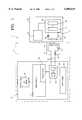
- FIG. 1shows a schematic block diagram of one embodiment of the present invention.
- FIG. 2shows a schematic block diagram of an alternative embodiment of the present invention.
- FIGS. 1 & 2schematically illustrate a device in accordance with two embodiments of the present invention for aiding the positioning of an external part relative to an implantable part of a charging system for charging a rechargeable power source of an implantable medical device.
- the charging system 1in accordance with one embodiment of the present invention, as shown in FIG. 1, has an external transmitting part 10 and an implantable receiving part 11.
- the external transmitting part 10includes a charging head 12 which contains a transmitting resonant circuit 13 with a transmitting coil 14 and a transmitting circuit capacitor 15 connected in series thus forming a series resonant circuit.
- the transmitting coil 14functions as a transmitter for the external transmission part 10.
- the charging head 12is connected via an electrically conductive link such as cables 16 to an output of a charging device 17 which is part of the external transmitting part 10.
- the transmitting resonant circuit 13is connected to a transmitting switching stage 18 which may include an oscillator such as a Donaldson oscillator 19 and a transmission end stage 20 connected downstream of the Donaldson oscillator 19.
- the implantable receiving part 11 in accordance with the present embodimentmay be a component of an implantable medical device generically labeled 22.
- the implantable receiving part 11includes a receiving resonant circuit 23 with a receiving coil 24 and a receiving circuit capacitor 25 connected in series, thus forming a series resonant circuit.
- the receiving coil 24serves as a receiver for the implantable receiving part 11.
- the receiving resonant circuit 23is connected to an input of a receiving switching stage 26 which includes a charging control circuit 27 and a power source 28 downstream of the charging control circuit 27.
- the power source 28may be in the form of a rechargeable DC voltage source including a rechargeable battery.
- the power source 28is used to supply power to an active medical implant 29 such as a hearing aid.
- the power source 28can be designed as a power supply module as shown in an commonly owned, co-pending U.S. patent application Ser. No. 09/359,050 claiming priority of the German patent application, 198 37 912.9-45 which is incorporated herein by reference.
- the charging control circuit 27 and the charging processcan be executed according to the commonly owned, copending U.S. patent application Ser. No. 09/311,566 filed on May 14, 1999 which is also incorporated herein by reference.
- the active medical implant 29such as a hearing aid, can be made for direct mechanical excitation of the middle ear or inner ear of the implant wearer.
- One such hearing aidis shown, for example, in U.S. Pat. No.
- the charging device 17also includes a micro-controller 32 which has a timer/counter 33, a LED display 34 connected to the microcontroller 32, and a power supply 35 for providing power to the components of the transmitting part 10.
- the charging head 12 of the external transmitting part 10is placed on the skin of the implant wearer and is manually positioned such that the transmitting coil 14 is aligned as much as possible with the receiving coil 24 so that the two coils together, form the primary and secondary circuit of a HF transformer and the receiving coil 24 can acquire electromagnetic energy from the transmitting coil 14.
- the positioning aid provided in the illustrated embodiment of the present inventionoperates based on the fact that the resonant frequency of the Donaldson oscillator 19 shifts as a function of the inductive coupling between the transmitting resonant circuit 13 and the receiving resonant circuit 23 such that detuning of the Donaldson oscillator 19 increases as coupling between the transmitting coil 14 and the receiving coil 24 increases. Since the inductive coupling is greatest when the transmitting coil 14 and the receiving coil 24 are aligned, the relative position of these coils 14, 24 can be derived from the amount of detuning present. Admittedly, the detuning depends fundamentally on the relative displacement of the transmitting coil 14 and the receiving coil 24 in all three axial directions.
- the distance between the coils in one axial directionis dictated in by the thickness of the skin or the tissue over the implantable medical device 22 and can be regarded as a constant.
- charging current flowing instantaneously in the receiving resonant circuit 23becomes part of the detuning such that with increasing charging of the power source 28, the detuning decreases.
- the positioning phaseis relatively short (generally at most one minute)
- the change of charging currentcan be ignored for positioning purposes, especially since generally, each charging process begins with the maximum possible charging current and the charging control circuit 27 controls the current only in a later phase of the charging process.
- the sign of the detuningshould be explicit.
- the implantable medical device 22is encapsulated in a metal jacket (not shown), for example a titanium jacket, it is desirable to be able to distinguish the resulting detuning in the coupling between the transmitting coil 14 and the receiving coil 24 from the detuning in coupling between the transmitting coil 14 and the metal jacket (not shown).
- the resonant frequency of the transmitting resonant circuit 13can be made to differ slightly from the resonant frequency of the receiving resonant circuit 23. In particular, the difference may be preferably roughly 0.5 to 3%.
- the resonant frequency of the transmitting resonant circuit 13is made to be less than the resonant frequency of the receiving resonant circuit 23 by preferably 1 to 2%.
- the frequency deviationbecomes negative as the coupling of the two circuits increases and the frequency deviation becomes positive when the transmitting coil 14 is coupled to the metal jacket (not shown) of the implantable medical device 22.
- the frequency detuning of the Donaldson oscillator 19can be determined by a measurement arrangement such as a microcontroller 32 which may include an integral counting circuit such as the timer/counter 33 which counts the oscillations of the Donaldson oscillator 19 per unit of time.
- the counting circuitcan be built as a discrete circuit.
- the counting circuitmay be integrated into the function of the microcontroller 32 as shown in the timer/counter 33 of FIG. 1.
- the value of the frequency deviationcan be determined by:
- the frequency detuning of the Donaldson oscillator 19can also be determined by measuring the period of the oscillator's oscillations.
- a discrete circuit(not shown) may be provided to accomplish this.
- such period measurementmay be integrated into the function of the microcontroller 32.
- the value of the frequency deviationcan be determined in a manner analogous to the aforementioned alternatives (a) and (b) except that the period of the oscillator's oscillations is measured.
- the measurement arrangementsuch as the microcontroller 32 may be provided with a means for measuring the basic period of the Donaldson oscillator 19 in the uncoupled state and for cyclic comparison measurement and difference formation in the coupled state, or the measurement arrangement can be equipped with means for computing the difference of two succeeding period values.
- the above explained measurementsare evaluated by an evaluation arrangement for outputting a positioning signal as a function of the ascertained frequency detuning of said oscillator.
- an evaluation arrangementsuch as a program executed and controlled by the microcontroller 32 is used.
- one or more threshold values and/or a self-adapting algorithmcan be programmed into the microcontroller 32 specifically to evaluate the measurement and to determine whether a positioning signal which indicates good or poor positioning should be provided.
- the evaluation arrangementcan be built as a discrete circuit but preferably, the microcontroller 32 may be used for this purpose.
- the evaluation arrangementsuch as the microcontroller 32 may then trigger a LED display 34 according to the results of the aforementioned evaluation of the measurement which will provided an indication whether the positioning is good or poor.
- the LED display 34may be a duo-LED display unit, for example, which lights red, orange, or green depending on the trigger signal of the microcontroller 32 and thus, clearly indicating to the implant wearer when the charging head 12 assumes a position in which satisfactory coupling of the transmitting coil 14 and the receiving coil 24 is established. It goes without saying that other optical display units may be provided. Furthermore, the proper positioning may also be indicated by a color change of a display and/or by triggering blinking at different rates.
- FIG. 2is very similar to the above discussed embodiment of FIG. 1 and operates similarly except that an alternative embodiment of the charging device 17' is shown which additionally includes a reference oscillator 41, a mixing stage 42, an amplifier 43 and a speaker 44.
- the reference oscillator 41generates a fixed reference frequency which is mixed in the mixing stage 42 with the frequency of the Donaldson oscillator 19 such that a signal in the audible frequency range is formed from the mixed frequency.
- This signalis amplified in an amplifier 43 and is delivered as an audible tone by the speaker 44.
- the tone level in this embodimentdepends on the quality of coupling between the transmitting coil 14 and the receiving coil 24 and thus, can be used as an indicator for the relative positioning of the charging head 12 and the implantable receiving part 11.
- the tone levelis set to maximum or minimum depending on the circuit design by the positioning of the transmitting coil 14 relative to the receiving coil 14 and may be set to vary accordingly.
Landscapes
- Health & Medical Sciences (AREA)
- Engineering & Computer Science (AREA)
- Biomedical Technology (AREA)
- Nuclear Medicine, Radiotherapy & Molecular Imaging (AREA)
- Radiology & Medical Imaging (AREA)
- Life Sciences & Earth Sciences (AREA)
- Animal Behavior & Ethology (AREA)
- General Health & Medical Sciences (AREA)
- Public Health (AREA)
- Veterinary Medicine (AREA)
- Electrotherapy Devices (AREA)
- Charge And Discharge Circuits For Batteries Or The Like (AREA)
Abstract
Description
Claims (25)
Applications Claiming Priority (2)
| Application Number | Priority Date | Filing Date | Title |
|---|---|---|---|
| DE19908438ADE19908438C2 (en) | 1999-02-26 | 1999-02-26 | Device and method for supporting the positioning of an external transmitting part with respect to an implantable receiving part of a charging system of an implantable medical device |
| DE19908438 | 1999-02-26 |
Publications (1)
| Publication Number | Publication Date |
|---|---|
| US6088619Atrue US6088619A (en) | 2000-07-11 |
Family
ID=7899023
Family Applications (1)
| Application Number | Title | Priority Date | Filing Date |
|---|---|---|---|
| US09/371,272Expired - LifetimeUS6088619A (en) | 1999-02-26 | 1999-08-10 | Device and method for aiding the positioning of an external part relative to an implantable part of a charging system for an implantable medical device |
Country Status (4)
| Country | Link |
|---|---|
| US (1) | US6088619A (en) |
| EP (1) | EP1032109B1 (en) |
| AT (1) | ATE276597T1 (en) |
| DE (1) | DE19908438C2 (en) |
Cited By (68)
| Publication number | Priority date | Publication date | Assignee | Title |
|---|---|---|---|---|
| US6540662B2 (en) | 1998-06-05 | 2003-04-01 | St. Croix Medical, Inc. | Method and apparatus for reduced feedback in implantable hearing assistance systems |
| WO2004021876A1 (en)* | 2002-09-04 | 2004-03-18 | Cochlear Limited | Method and apparatus for measurement of transmitter/receiver separation |
| WO2004028623A1 (en)* | 2002-09-25 | 2004-04-08 | Potencia Medical Ag | Detection of implanted wireless energy receiving device |
| US6730015B2 (en) | 2001-06-01 | 2004-05-04 | Mike Schugt | Flexible transducer supports |
| WO2004052450A1 (en)* | 2002-12-12 | 2004-06-24 | Metin Tulgar | Externally activated neuro-implant which directly transmits therapeutic signals |
| US20050075697A1 (en)* | 2003-10-02 | 2005-04-07 | Medtronic, Inc. | External power source for an implantable medical device having an adjustable carrier frequency and system and method related therefore |
| US20050165461A1 (en)* | 2002-05-23 | 2005-07-28 | Harumi Takeda | Non-intrusion type charging system for artificial organ, capacitor and power supplying device used in the system |
| US20060016452A1 (en)* | 2004-07-20 | 2006-01-26 | Medtronic, Inc. | Locating an implanted object based on external antenna loading |
| US20060095014A1 (en)* | 2003-05-08 | 2006-05-04 | Novo Nordisk A/S | External inserter for transcutaneous device |
| US20060142698A1 (en)* | 2003-05-08 | 2006-06-29 | Novo Nordisk A/S | Internal needle inserter |
| US20060247737A1 (en)* | 2005-04-29 | 2006-11-02 | Medtronic, Inc. | Alignment indication for transcutaneous energy transfer |
| US20070021733A1 (en)* | 2003-10-21 | 2007-01-25 | Novo Nordisk A/S | Internal fluid connector |
| US20070028927A1 (en)* | 2003-12-12 | 2007-02-08 | Slattery William H Iii | Surgical instrument set and procedure for implanting sound transducer proximate to patient's outer ear canal |
| US20070049865A1 (en)* | 2003-08-01 | 2007-03-01 | Novo Nordisk A/S | Retraction means for transcutaneous device |
| US20070068350A1 (en)* | 2003-10-09 | 2007-03-29 | Star Micronics Co., Ltd. | Nc automatic lathe |
| US20070104596A1 (en)* | 2004-03-30 | 2007-05-10 | Novo Nordisk A/S | Actuator system comprising lever mechanism |
| WO2007104756A1 (en)* | 2006-03-13 | 2007-09-20 | Novo Nordisk A/S | Medical system comprising dual purpose communication means |
| US20070233205A1 (en)* | 2001-06-06 | 2007-10-04 | Cochlear Limited | Monitor for auditory prosthesis |
| US20080083413A1 (en)* | 2002-10-01 | 2008-04-10 | Potencia Medical Ag | Detection of implanted injection port |
| CN100386916C (en)* | 2006-04-28 | 2008-05-07 | 清华大学 | Transcutaneous Wireless Charging Devices for Implantable Medical Instruments |
| US20080167641A1 (en)* | 2005-05-13 | 2008-07-10 | Novo Nordisk A/S | Medical Device Adapted To Detect Disengagement Of A Transcutaneous Device |
| US20080215006A1 (en)* | 2004-09-22 | 2008-09-04 | Novo Nordisk A/S | Medical Device with Transcutaneous Cannula Device |
| US20090012472A1 (en)* | 2004-09-22 | 2009-01-08 | Novo Nordisk A/S | Medical Device with Cannula Inserter |
| US20090048563A1 (en)* | 2004-12-06 | 2009-02-19 | Novo Nordisk A/S | Ventilated Skin Mountable Device |
| US20090076451A1 (en)* | 2005-01-24 | 2009-03-19 | Nova Nordisk A/S | Medical Device with Protected Transcutaneous Device |
| US20090163874A1 (en)* | 2006-04-26 | 2009-06-25 | Novo Nordisk A/S | Skin-Mountable Device in Packaging Comprising Coated Seal Member |
| US20100063448A1 (en)* | 2007-03-06 | 2010-03-11 | Novo Nordisk A/S | Pump assembly comprising actuator system |
| US20110009924A1 (en)* | 2009-07-10 | 2011-01-13 | Werner Meskens | Varying the effective coil area for an inductive transcutaneous power link |
| US20110008206A1 (en)* | 2007-10-31 | 2011-01-13 | Novo Nordisk A/S | Non-Porous Material as Sterilization Barrier |
| CN101980412A (en)* | 2010-09-27 | 2011-02-23 | 清华大学 | A Percutaneous Closed-Loop Controlled Charging Device for Implantable Medical Instruments |
| US20110060289A1 (en)* | 2003-05-08 | 2011-03-10 | Novo Nordisk A/S | Integrated package |
| US8430805B2 (en) | 2006-10-02 | 2013-04-30 | Emkinetics, Inc. | Method and apparatus for magnetic induction therapy |
| US8588884B2 (en) | 2010-05-28 | 2013-11-19 | Emkinetics, Inc. | Microneedle electrode |
| US8594806B2 (en) | 2010-04-30 | 2013-11-26 | Cyberonics, Inc. | Recharging and communication lead for an implantable device |
| US20140222112A1 (en)* | 2011-07-19 | 2014-08-07 | Greatbatch Ltd. | Devices and methods for visually indicating the alignment of a transcutaneous energy transfer device over an implanted medical device |
| US9002477B2 (en) | 2006-01-17 | 2015-04-07 | Emkinetics, Inc. | Methods and devices for performing electrical stimulation to treat various conditions |
| US9005102B2 (en) | 2006-10-02 | 2015-04-14 | Emkinetics, Inc. | Method and apparatus for electrical stimulation therapy |
| US9173992B2 (en) | 2006-03-13 | 2015-11-03 | Novo Nordisk A/S | Secure pairing of electronic devices using dual means of communication |
| US20160114173A1 (en)* | 2008-12-03 | 2016-04-28 | Boston Scientific Neuromodulation Corporation | External charger with adjustable alignment indicator |
| US9339641B2 (en) | 2006-01-17 | 2016-05-17 | Emkinetics, Inc. | Method and apparatus for transdermal stimulation over the palmar and plantar surfaces |
| US9343923B2 (en) | 2012-08-23 | 2016-05-17 | Cyberonics, Inc. | Implantable medical device with backscatter signal based communication |
| US9399094B2 (en) | 2006-06-06 | 2016-07-26 | Novo Nordisk A/S | Assembly comprising skin-mountable device and packaging therefore |
| US9610459B2 (en) | 2009-07-24 | 2017-04-04 | Emkinetics, Inc. | Cooling systems and methods for conductive coils |
| US9707406B1 (en) | 2016-01-06 | 2017-07-18 | Syntilla Medical LLC | Charging system incorporating receive coil de-tuning within an implanted device |
| US9788756B2 (en) | 2015-04-20 | 2017-10-17 | Medtronic, Inc. | Systems, devices, methods, and computer-readable storage facilitating locating an implantable medical device within a body |
| WO2017218350A1 (en)* | 2016-06-15 | 2017-12-21 | Boston Scientific Neuromodulation Corporation | External charger for an implantable medical device having alignment and centering capabilities |
| WO2017218352A1 (en)* | 2016-06-15 | 2017-12-21 | Boston Scientific Neuromodulation Corporation | External charger for an implantable medical device for adjusting charging power based on determined position using at least one sense coil |
| US9855376B2 (en) | 2014-07-25 | 2018-01-02 | Minnetronix, Inc. | Power scaling |
| US9884190B2 (en) | 2013-08-14 | 2018-02-06 | Syntilla Medical LLC | Surgical method for implantable head mounted neurostimulation system for head pain |
| US9889308B2 (en) | 2013-10-23 | 2018-02-13 | Syntilla Medical LLC | Implantable head located radiofrequency coupled neurostimulation system for head pain |
| US9935498B2 (en) | 2012-09-25 | 2018-04-03 | Cyberonics, Inc. | Communication efficiency with an implantable medical device using a circulator and a backscatter signal |
| CN107923767A (en)* | 2015-08-28 | 2018-04-17 | 罗伯特·博世有限公司 | Method and apparatus for determining cell winding inductance |
| US10149933B2 (en) | 2014-07-25 | 2018-12-11 | Minnetronix, Inc. | Coil parameters and control |
| CN109001615A (en)* | 2018-07-23 | 2018-12-14 | 清华大学 | Auto-Test System for the detection of active implantation medical equipment |
| US10193395B2 (en) | 2015-04-14 | 2019-01-29 | Minnetronix, Inc. | Repeater resonator |
| US10258805B2 (en) | 2013-10-23 | 2019-04-16 | Syntilla Medical, Llc | Surgical method for implantable head mounted neurostimulation system for head pain |
| US10342908B2 (en) | 2015-01-14 | 2019-07-09 | Minnetronix, Inc. | Distributed transformer |
| US10363426B2 (en) | 2016-06-15 | 2019-07-30 | Boston Scientific Neuromodulation Corporation | External charger for an implantable medical device for determining position using phase angle or a plurality of parameters as determined from at least one sense coil |
| US10406267B2 (en) | 2015-01-16 | 2019-09-10 | Minnetronix, Inc. | Data communication in a transcutaneous energy transfer system |
| US20190298485A1 (en)* | 2008-10-10 | 2019-10-03 | Peter Forsell | Charger for an implant |
| US10603501B2 (en) | 2016-06-15 | 2020-03-31 | Boston Scientific Neuromodulation Corporation | External charger for an implantable medical device having at least one sense coil concentric with a charging coil for determining position |
| US10786669B2 (en) | 2006-10-02 | 2020-09-29 | Emkinetics, Inc. | Method and apparatus for transdermal stimulation over the palmar and plantar surfaces |
| US10960215B2 (en) | 2013-10-23 | 2021-03-30 | Nuxcel, Inc. | Low profile head-located neurostimulator and method of fabrication |
| US11129996B2 (en) | 2016-06-15 | 2021-09-28 | Boston Scientific Neuromodulation Corporation | External charger for an implantable medical device for determining position and optimizing power transmission using resonant frequency as determined from at least one sense coil |
| US11224742B2 (en) | 2006-10-02 | 2022-01-18 | Emkinetics, Inc. | Methods and devices for performing electrical stimulation to treat various conditions |
| WO2022079505A1 (en)* | 2020-10-13 | 2022-04-21 | Cochlear Limited | Skin flap thickness estimation |
| US20220183559A1 (en)* | 2020-12-16 | 2022-06-16 | Peter Forsell | Charger for an implant |
| US12376787B2 (en) | 2020-07-21 | 2025-08-05 | DePuy Synthes Products, Inc. | Bone fixation monitoring system |
Families Citing this family (1)
| Publication number | Priority date | Publication date | Assignee | Title |
|---|---|---|---|---|
| DE102013108733A1 (en)* | 2013-08-12 | 2015-02-12 | Wittenstein Ag | Device and method for aligning a primary device |
Citations (4)
| Publication number | Priority date | Publication date | Assignee | Title |
|---|---|---|---|---|
| US5277694A (en)* | 1991-02-13 | 1994-01-11 | Implex Gmbh | Electromechanical transducer for implantable hearing aids |
| US5279292A (en)* | 1991-02-13 | 1994-01-18 | Implex Gmbh | Charging system for implantable hearing aids and tinnitus maskers |
| US5690693A (en)* | 1995-06-07 | 1997-11-25 | Sulzer Intermedics Inc. | Transcutaneous energy transmission circuit for implantable medical device |
| US5814095A (en)* | 1996-09-18 | 1998-09-29 | Implex Gmbh Spezialhorgerate | Implantable microphone and implantable hearing aids utilizing same |
Family Cites Families (2)
| Publication number | Priority date | Publication date | Assignee | Title |
|---|---|---|---|---|
| DE19837912C1 (en)* | 1998-08-20 | 1999-10-28 | Implex Hear Tech Ag | Energy supply module for implanted device e.g. hearing aid or tinnitus masking device, heart pacemaker or drug dispenser |
| DE19838137A1 (en)* | 1998-08-21 | 2000-03-02 | Implex Hear Tech Ag | Charger arrangement for rechargeable Ni Cd, Ni-metal hydride, or Lithium batteries in implant, has current source which provides high initial current |
- 1999
- 1999-02-26DEDE19908438Apatent/DE19908438C2/ennot_activeExpired - Fee Related
- 1999-08-10USUS09/371,272patent/US6088619A/ennot_activeExpired - Lifetime
- 1999-11-15ATAT99122695Tpatent/ATE276597T1/ennot_activeIP Right Cessation
- 1999-11-15EPEP99122695Apatent/EP1032109B1/ennot_activeExpired - Lifetime
Patent Citations (4)
| Publication number | Priority date | Publication date | Assignee | Title |
|---|---|---|---|---|
| US5277694A (en)* | 1991-02-13 | 1994-01-11 | Implex Gmbh | Electromechanical transducer for implantable hearing aids |
| US5279292A (en)* | 1991-02-13 | 1994-01-18 | Implex Gmbh | Charging system for implantable hearing aids and tinnitus maskers |
| US5690693A (en)* | 1995-06-07 | 1997-11-25 | Sulzer Intermedics Inc. | Transcutaneous energy transmission circuit for implantable medical device |
| US5814095A (en)* | 1996-09-18 | 1998-09-29 | Implex Gmbh Spezialhorgerate | Implantable microphone and implantable hearing aids utilizing same |
Non-Patent Citations (3)
| Title |
|---|
| Leysieffer et al., A Completely Implantable Hearing System for the Hearing Impaired: TICA LZ 3001, HNO 46:853 863, (1998).* |
| Leysieffer et al., A Completely Implantable Hearing System for the Hearing Impaired: TICA LZ 3001, HNO 46:853-863, (1998). |
| P.E.K. Donaldson, Power for Neurological Prostheses: A Simple Inductive R.F. Link with Improved Performance, J. Biomed. Eng., vol. 9, (Jul., 1987).* |
Cited By (146)
| Publication number | Priority date | Publication date | Assignee | Title |
|---|---|---|---|---|
| US6755778B2 (en) | 1998-06-05 | 2004-06-29 | St. Croix Medical, Inc. | Method and apparatus for reduced feedback in implantable hearing assistance systems |
| US6540662B2 (en) | 1998-06-05 | 2003-04-01 | St. Croix Medical, Inc. | Method and apparatus for reduced feedback in implantable hearing assistance systems |
| US6730015B2 (en) | 2001-06-01 | 2004-05-04 | Mike Schugt | Flexible transducer supports |
| US20070233205A1 (en)* | 2001-06-06 | 2007-10-04 | Cochlear Limited | Monitor for auditory prosthesis |
| US20050165461A1 (en)* | 2002-05-23 | 2005-07-28 | Harumi Takeda | Non-intrusion type charging system for artificial organ, capacitor and power supplying device used in the system |
| US8000800B2 (en) | 2002-05-23 | 2011-08-16 | Limited Company Tm | Contactless charging system for an artificial organ, a storage device and a feeding device for use with this system |
| EP1513241A4 (en)* | 2002-05-23 | 2008-10-01 | Ltd Company Tm | Non-intrusion type charging system for artificial organ, capacitor and power supplying device used in the system |
| US8452412B2 (en) | 2002-09-04 | 2013-05-28 | Cochlear Limited | Measurement of transmitter/receiver separation |
| US20070100395A1 (en)* | 2002-09-04 | 2007-05-03 | Ibrahim Ibrahim H | Method and apparatus for measurement of transmitter/receiver separation |
| WO2004021876A1 (en)* | 2002-09-04 | 2004-03-18 | Cochlear Limited | Method and apparatus for measurement of transmitter/receiver separation |
| US20040250820A1 (en)* | 2002-09-25 | 2004-12-16 | Potencia Medical Ag | Detection of implanted wireless energy receiving device |
| WO2004028623A1 (en)* | 2002-09-25 | 2004-04-08 | Potencia Medical Ag | Detection of implanted wireless energy receiving device |
| US20080083413A1 (en)* | 2002-10-01 | 2008-04-10 | Potencia Medical Ag | Detection of implanted injection port |
| WO2004052450A1 (en)* | 2002-12-12 | 2004-06-24 | Metin Tulgar | Externally activated neuro-implant which directly transmits therapeutic signals |
| US20060142822A1 (en)* | 2002-12-12 | 2006-06-29 | Metin Tulgar | Externally activated neuro-implant which directly transmits therapeutic signals |
| US7981085B2 (en) | 2003-05-08 | 2011-07-19 | Novo Nordisk A/S | Internal needle inserter |
| US20110060289A1 (en)* | 2003-05-08 | 2011-03-10 | Novo Nordisk A/S | Integrated package |
| US8740851B2 (en) | 2003-05-08 | 2014-06-03 | Novo Nordisk A/S | Integrated package |
| US20060142698A1 (en)* | 2003-05-08 | 2006-06-29 | Novo Nordisk A/S | Internal needle inserter |
| US20060095014A1 (en)* | 2003-05-08 | 2006-05-04 | Novo Nordisk A/S | External inserter for transcutaneous device |
| US8029469B2 (en) | 2003-05-08 | 2011-10-04 | Novo Nordisk A/S | External inserter for transcutaneous device |
| US20070049865A1 (en)* | 2003-08-01 | 2007-03-01 | Novo Nordisk A/S | Retraction means for transcutaneous device |
| US7955297B2 (en) | 2003-08-01 | 2011-06-07 | Novo Nordisk A/S | Retraction means for transcutaneous device |
| US8630717B2 (en) | 2003-10-02 | 2014-01-14 | Medtronic, Inc. | External power source for an implantable medical device having an adjustable carrier frequency and system and method related therefore |
| US8140168B2 (en) | 2003-10-02 | 2012-03-20 | Medtronic, Inc. | External power source for an implantable medical device having an adjustable carrier frequency and system and method related therefore |
| US20050075697A1 (en)* | 2003-10-02 | 2005-04-07 | Medtronic, Inc. | External power source for an implantable medical device having an adjustable carrier frequency and system and method related therefore |
| WO2005037365A1 (en)* | 2003-10-02 | 2005-04-28 | Medtronic, Inc. | External power source for an implantable medical device having an adjustable carrier frequency and system and method related therefore |
| US20070068350A1 (en)* | 2003-10-09 | 2007-03-29 | Star Micronics Co., Ltd. | Nc automatic lathe |
| US20070021733A1 (en)* | 2003-10-21 | 2007-01-25 | Novo Nordisk A/S | Internal fluid connector |
| US7922647B2 (en) | 2003-12-12 | 2011-04-12 | Advanced Bionics Ag | Surgical instrument set and procedure for implanting sound transducer proximate to patient's outer ear canal |
| US20070028927A1 (en)* | 2003-12-12 | 2007-02-08 | Slattery William H Iii | Surgical instrument set and procedure for implanting sound transducer proximate to patient's outer ear canal |
| US20070104596A1 (en)* | 2004-03-30 | 2007-05-10 | Novo Nordisk A/S | Actuator system comprising lever mechanism |
| US20110166524A1 (en)* | 2004-03-30 | 2011-07-07 | Novo Nordisk A/S | Actuator System Comprising Lever Mechanism |
| US7922462B2 (en) | 2004-03-30 | 2011-04-12 | Novo Nordisk A/S | Actuator system comprising lever mechanism |
| WO2006012426A3 (en)* | 2004-07-20 | 2006-03-16 | Medtronic Inc | Locating an implanted object based on external antenna loading |
| US20110118591A1 (en)* | 2004-07-20 | 2011-05-19 | Medtronic, Inc. | Locating an implanted object based on external antenna loading |
| US8015978B2 (en) | 2004-07-20 | 2011-09-13 | Medtronic, Inc. | Locating an implanted object based on external antenna loading |
| US7878207B2 (en) | 2004-07-20 | 2011-02-01 | Medtronic, Inc. | Locating an implanted object based on external antenna loading |
| US20060016452A1 (en)* | 2004-07-20 | 2006-01-26 | Medtronic, Inc. | Locating an implanted object based on external antenna loading |
| US20080215006A1 (en)* | 2004-09-22 | 2008-09-04 | Novo Nordisk A/S | Medical Device with Transcutaneous Cannula Device |
| US20090012472A1 (en)* | 2004-09-22 | 2009-01-08 | Novo Nordisk A/S | Medical Device with Cannula Inserter |
| US20090048563A1 (en)* | 2004-12-06 | 2009-02-19 | Novo Nordisk A/S | Ventilated Skin Mountable Device |
| US8167841B2 (en) | 2005-01-24 | 2012-05-01 | Novo Nordisk A/S | Transcutaneous device assembly |
| US20090076451A1 (en)* | 2005-01-24 | 2009-03-19 | Nova Nordisk A/S | Medical Device with Protected Transcutaneous Device |
| US8024047B2 (en) | 2005-04-29 | 2011-09-20 | Medtronic, Inc. | Alignment indication for transcutaneous energy transfer |
| US20060247737A1 (en)* | 2005-04-29 | 2006-11-02 | Medtronic, Inc. | Alignment indication for transcutaneous energy transfer |
| US7774069B2 (en)* | 2005-04-29 | 2010-08-10 | Medtronic, Inc. | Alignment indication for transcutaneous energy transfer |
| US20100268305A1 (en)* | 2005-04-29 | 2010-10-21 | Medtronic, Inc. | Alignment indication for transcutaneous energy transfer |
| US8457758B2 (en) | 2005-04-29 | 2013-06-04 | Medtronic, Inc. | Alignment indication for transcutaneous energy transfer |
| US20080167641A1 (en)* | 2005-05-13 | 2008-07-10 | Novo Nordisk A/S | Medical Device Adapted To Detect Disengagement Of A Transcutaneous Device |
| US9757584B2 (en) | 2006-01-17 | 2017-09-12 | Emkinetics, Inc. | Methods and devices for performing electrical stimulation to treat various conditions |
| US9387338B2 (en) | 2006-01-17 | 2016-07-12 | Emkinetics, Inc. | Methods and devices for performing electrical stimulation to treat various conditions |
| US9339641B2 (en) | 2006-01-17 | 2016-05-17 | Emkinetics, Inc. | Method and apparatus for transdermal stimulation over the palmar and plantar surfaces |
| US9002477B2 (en) | 2006-01-17 | 2015-04-07 | Emkinetics, Inc. | Methods and devices for performing electrical stimulation to treat various conditions |
| US9630004B2 (en) | 2006-01-17 | 2017-04-25 | Emkinetics, Inc. | Method and apparatus for transdermal stimulation over the palmar and plantar surfaces |
| US9173992B2 (en) | 2006-03-13 | 2015-11-03 | Novo Nordisk A/S | Secure pairing of electronic devices using dual means of communication |
| US20090062778A1 (en)* | 2006-03-13 | 2009-03-05 | Novo Nordisk A/S | Medical System Comprising Dual-Purpose Communication Means |
| WO2007104756A1 (en)* | 2006-03-13 | 2007-09-20 | Novo Nordisk A/S | Medical system comprising dual purpose communication means |
| US20090163874A1 (en)* | 2006-04-26 | 2009-06-25 | Novo Nordisk A/S | Skin-Mountable Device in Packaging Comprising Coated Seal Member |
| CN100386916C (en)* | 2006-04-28 | 2008-05-07 | 清华大学 | Transcutaneous Wireless Charging Devices for Implantable Medical Instruments |
| US9399094B2 (en) | 2006-06-06 | 2016-07-26 | Novo Nordisk A/S | Assembly comprising skin-mountable device and packaging therefore |
| US11224742B2 (en) | 2006-10-02 | 2022-01-18 | Emkinetics, Inc. | Methods and devices for performing electrical stimulation to treat various conditions |
| US11628300B2 (en) | 2006-10-02 | 2023-04-18 | Emkinetics, Inc. | Method and apparatus for transdermal stimulation over the palmar and plantar surfaces |
| US12226632B2 (en) | 2006-10-02 | 2025-02-18 | Emkinetics, Inc. | Method and apparatus for transdermal stimulation over the palmar and plantar surfaces |
| US8435166B2 (en) | 2006-10-02 | 2013-05-07 | Emkinetics, Inc. | Method and apparatus for magnetic induction therapy |
| US8430805B2 (en) | 2006-10-02 | 2013-04-30 | Emkinetics, Inc. | Method and apparatus for magnetic induction therapy |
| US10786669B2 (en) | 2006-10-02 | 2020-09-29 | Emkinetics, Inc. | Method and apparatus for transdermal stimulation over the palmar and plantar surfaces |
| US9005102B2 (en) | 2006-10-02 | 2015-04-14 | Emkinetics, Inc. | Method and apparatus for electrical stimulation therapy |
| US11247053B2 (en) | 2006-10-02 | 2022-02-15 | Emkinetics, Inc. | Method and apparatus for transdermal stimulation over the palmar and plantar surfaces |
| US12083334B2 (en) | 2006-10-02 | 2024-09-10 | Emkinetics, Inc. | Methods and devices for performing electrical stimulation to treat dysmenorrhea or menstrual cramps |
| US11844943B2 (en) | 2006-10-02 | 2023-12-19 | Emkinetics, Inc. | Method and apparatus for transdermal stimulation over the palmar and plantar surfaces |
| US20100063448A1 (en)* | 2007-03-06 | 2010-03-11 | Novo Nordisk A/S | Pump assembly comprising actuator system |
| US8557179B2 (en) | 2007-10-31 | 2013-10-15 | Novo Nordisk A/S | Non-porous material as sterilization barrier |
| US20110008206A1 (en)* | 2007-10-31 | 2011-01-13 | Novo Nordisk A/S | Non-Porous Material as Sterilization Barrier |
| US10874479B2 (en)* | 2008-10-10 | 2020-12-29 | Peter Forsell | Charger for an implant |
| US20190298485A1 (en)* | 2008-10-10 | 2019-10-03 | Peter Forsell | Charger for an implant |
| US20160114173A1 (en)* | 2008-12-03 | 2016-04-28 | Boston Scientific Neuromodulation Corporation | External charger with adjustable alignment indicator |
| US10737103B2 (en) | 2008-12-03 | 2020-08-11 | Boston Scientific Neuromodulation Corporation | External charger with adjustable alignment indicator |
| US10010717B2 (en)* | 2008-12-03 | 2018-07-03 | Boston Scientific Neuromodulation Corporation | External charger with adjustable alignment indicator |
| US8996121B2 (en) | 2009-07-10 | 2015-03-31 | Cochlear Limited | Varying the effective coil area for an inductive transcutaneous power link |
| US20150202438A1 (en)* | 2009-07-10 | 2015-07-23 | Cochlear Limited | Varying the effective coil area for an inductive transcutaneous power link |
| US10080893B2 (en)* | 2009-07-10 | 2018-09-25 | Cochlear Limited | Varying the effective coil area for an inductive transcutaneous power link |
| US20110009924A1 (en)* | 2009-07-10 | 2011-01-13 | Werner Meskens | Varying the effective coil area for an inductive transcutaneous power link |
| US9610459B2 (en) | 2009-07-24 | 2017-04-04 | Emkinetics, Inc. | Cooling systems and methods for conductive coils |
| US8594806B2 (en) | 2010-04-30 | 2013-11-26 | Cyberonics, Inc. | Recharging and communication lead for an implantable device |
| US8588884B2 (en) | 2010-05-28 | 2013-11-19 | Emkinetics, Inc. | Microneedle electrode |
| CN101980412A (en)* | 2010-09-27 | 2011-02-23 | 清华大学 | A Percutaneous Closed-Loop Controlled Charging Device for Implantable Medical Instruments |
| CN101980412B (en)* | 2010-09-27 | 2013-01-30 | 清华大学 | A Percutaneous Closed-Loop Controlled Charging Device for Implantable Medical Instruments |
| US9031666B2 (en)* | 2011-07-19 | 2015-05-12 | Greatbatch Ltd. | Devices and methods for visually indicating the alignment of a transcutaneous energy transfer device over an implanted medical device |
| US20150231392A1 (en)* | 2011-07-19 | 2015-08-20 | Greatbatch Ltd. | Devices and methods for visually indicating the alignment of a transcutaneous energy transfer device over an implanted medical device |
| US20140222112A1 (en)* | 2011-07-19 | 2014-08-07 | Greatbatch Ltd. | Devices and methods for visually indicating the alignment of a transcutaneous energy transfer device over an implanted medical device |
| US9375567B2 (en)* | 2011-07-19 | 2016-06-28 | Nuvectra Corporation | Devices and methods for visually indicating the alignment of a transcutaneous energy transfer device over an implanted medical device |
| US9343923B2 (en) | 2012-08-23 | 2016-05-17 | Cyberonics, Inc. | Implantable medical device with backscatter signal based communication |
| US9935498B2 (en) | 2012-09-25 | 2018-04-03 | Cyberonics, Inc. | Communication efficiency with an implantable medical device using a circulator and a backscatter signal |
| US9884190B2 (en) | 2013-08-14 | 2018-02-06 | Syntilla Medical LLC | Surgical method for implantable head mounted neurostimulation system for head pain |
| US10960215B2 (en) | 2013-10-23 | 2021-03-30 | Nuxcel, Inc. | Low profile head-located neurostimulator and method of fabrication |
| US9889308B2 (en) | 2013-10-23 | 2018-02-13 | Syntilla Medical LLC | Implantable head located radiofrequency coupled neurostimulation system for head pain |
| US12070610B2 (en) | 2013-10-23 | 2024-08-27 | Shiratronics, Inc. | Low profile head-located neurostimulator |
| US11623100B2 (en) | 2013-10-23 | 2023-04-11 | Shiratronics, Inc. | Low profile head-located neurostimulator |
| US11612756B2 (en) | 2013-10-23 | 2023-03-28 | Shiratronics, Inc. | Implantable head mounted neurostimulation system for head pain |
| US11400302B2 (en) | 2013-10-23 | 2022-08-02 | Shiratronics, Inc. | Surgical method for implantable neurostimulation system for pain |
| US11357995B2 (en) | 2013-10-23 | 2022-06-14 | Shiratronics, Inc. | Implantable head located radiofrequency coupled neurostimulation system for head pain |
| US10946205B2 (en) | 2013-10-23 | 2021-03-16 | Nuxcel, Inc. | Implantable head mounted neurostimulation system for head pain |
| US10850112B2 (en) | 2013-10-23 | 2020-12-01 | Nuxcel, Inc. | Surgical method for implantable neurostimulation system for pain |
| US10258805B2 (en) | 2013-10-23 | 2019-04-16 | Syntilla Medical, Llc | Surgical method for implantable head mounted neurostimulation system for head pain |
| US10695571B2 (en) | 2013-10-23 | 2020-06-30 | Nuxcel, Inc. | Implantable head located radiofrequency coupled neurostimulation system for head pain |
| US10898628B2 (en) | 2014-07-25 | 2021-01-26 | Minnetronix, Inc. | Coil parameters and control |
| US9855376B2 (en) | 2014-07-25 | 2018-01-02 | Minnetronix, Inc. | Power scaling |
| US10149933B2 (en) | 2014-07-25 | 2018-12-11 | Minnetronix, Inc. | Coil parameters and control |
| US10376625B2 (en) | 2014-07-25 | 2019-08-13 | Minnetronix, Inc. | Power scaling |
| US11207516B2 (en) | 2015-01-14 | 2021-12-28 | Minnetronix, Inc. | Distributed transformer |
| US10342908B2 (en) | 2015-01-14 | 2019-07-09 | Minnetronix, Inc. | Distributed transformer |
| US10406267B2 (en) | 2015-01-16 | 2019-09-10 | Minnetronix, Inc. | Data communication in a transcutaneous energy transfer system |
| US11235141B2 (en) | 2015-01-16 | 2022-02-01 | Minnetronix, Inc. | Data communication in a transcutaneous energy transfer system |
| US10193395B2 (en) | 2015-04-14 | 2019-01-29 | Minnetronix, Inc. | Repeater resonator |
| US11894695B2 (en) | 2015-04-14 | 2024-02-06 | Minnetronix, Inc. | Repeater resonator |
| US9788756B2 (en) | 2015-04-20 | 2017-10-17 | Medtronic, Inc. | Systems, devices, methods, and computer-readable storage facilitating locating an implantable medical device within a body |
| CN107923767A (en)* | 2015-08-28 | 2018-04-17 | 罗伯特·博世有限公司 | Method and apparatus for determining cell winding inductance |
| CN107923767B (en)* | 2015-08-28 | 2021-02-05 | 罗伯特·博世有限公司 | Method and apparatus for determining sensor coil inductance |
| US9833629B2 (en) | 2016-01-06 | 2017-12-05 | Syntilla Medical LLC | Charging system providing adjustable transmitted power to improve power efficiency within an implanted device |
| US9717917B2 (en) | 2016-01-06 | 2017-08-01 | Syntilla Medical LLC | Charging system incorporating independent charging and communication with multiple implanted devices |
| US10022549B2 (en)* | 2016-01-06 | 2018-07-17 | Syntilla Medical LLC | Charging system incorporating data communication and power transmission using opposite polarity half-wave rectified signals received by implanted device |
| US9757575B2 (en) | 2016-01-06 | 2017-09-12 | Syntilla Medical LLC | Charging system including transmit coil current sensing circuitry |
| US9839788B2 (en) | 2016-01-06 | 2017-12-12 | Syntilla Medical LLC | Charging system incorporating bi-directional communication with implanted device |
| US9707406B1 (en) | 2016-01-06 | 2017-07-18 | Syntilla Medical LLC | Charging system incorporating receive coil de-tuning within an implanted device |
| US9713726B1 (en) | 2016-01-06 | 2017-07-25 | Syntilla Medical LLC | Charging system incorporating feedback excitation control of resonant coil driver amplifier |
| US10603501B2 (en) | 2016-06-15 | 2020-03-31 | Boston Scientific Neuromodulation Corporation | External charger for an implantable medical device having at least one sense coil concentric with a charging coil for determining position |
| CN109310868B (en)* | 2016-06-15 | 2022-07-15 | 波士顿科学神经调制公司 | External charger for an implantable medical device that adjusts charging power based on a position determined with at least one sensing coil |
| US11129996B2 (en) | 2016-06-15 | 2021-09-28 | Boston Scientific Neuromodulation Corporation | External charger for an implantable medical device for determining position and optimizing power transmission using resonant frequency as determined from at least one sense coil |
| US10960219B2 (en) | 2016-06-15 | 2021-03-30 | Boston Scientific Neuromodulation Corporation | External charger for an implantable medical device having alignment and centering capabilities |
| EP3988163A1 (en)* | 2016-06-15 | 2022-04-27 | Boston Scientific Neuromodulation Corporation | External charger for an implantable medical device for adjusting charging power based on determined position using at least one sense coil |
| CN109310867A (en)* | 2016-06-15 | 2019-02-05 | 波士顿科学神经调制公司 | The external charger for implantable medical device with alignment and centering ability |
| US12115377B2 (en) | 2016-06-15 | 2024-10-15 | Boston Scientific Neuromodulation Corporation | External charger for an implantable medical device for adjusting charging power based on determined position using at least one sense coil |
| US10632319B2 (en) | 2016-06-15 | 2020-04-28 | Boston Scientific Neuromodulation Corporation | External charger for an implantable medical device for determining position using phase angle or a plurality of parameters as determined from at least one sense coil |
| US10576294B2 (en) | 2016-06-15 | 2020-03-03 | Boston Scientific Neuromodulation Corporation | External charger for an implantable medical device having alignment and centering capabilities |
| US11471692B2 (en) | 2016-06-15 | 2022-10-18 | Boston Scientific Neuromodulation Corporation | External charger for an implantable medical device for adjusting charging power based on determined position using at least one sense coil |
| WO2017218352A1 (en)* | 2016-06-15 | 2017-12-21 | Boston Scientific Neuromodulation Corporation | External charger for an implantable medical device for adjusting charging power based on determined position using at least one sense coil |
| US10363426B2 (en) | 2016-06-15 | 2019-07-30 | Boston Scientific Neuromodulation Corporation | External charger for an implantable medical device for determining position using phase angle or a plurality of parameters as determined from at least one sense coil |
| CN109310868A (en)* | 2016-06-15 | 2019-02-05 | 波士顿科学神经调制公司 | An external charger for an implantable medical device that adjusts charging power based on a position determined with at least one sense coil |
| US10881870B2 (en) | 2016-06-15 | 2021-01-05 | Boston Scientific Neuromodulation Corporation | External charger for an implantable medical device having at least one sense coil concentric with a charging coil for determining position |
| WO2017218350A1 (en)* | 2016-06-15 | 2017-12-21 | Boston Scientific Neuromodulation Corporation | External charger for an implantable medical device having alignment and centering capabilities |
| US10226637B2 (en) | 2016-06-15 | 2019-03-12 | Boston Scientific Neuromodulation Corporation | External charger for an implantable medical device having alignment and centering capabilities |
| CN109001615A (en)* | 2018-07-23 | 2018-12-14 | 清华大学 | Auto-Test System for the detection of active implantation medical equipment |
| US12376787B2 (en) | 2020-07-21 | 2025-08-05 | DePuy Synthes Products, Inc. | Bone fixation monitoring system |
| WO2022079505A1 (en)* | 2020-10-13 | 2022-04-21 | Cochlear Limited | Skin flap thickness estimation |
| US20220183559A1 (en)* | 2020-12-16 | 2022-06-16 | Peter Forsell | Charger for an implant |
Also Published As
| Publication number | Publication date |
|---|---|
| ATE276597T1 (en) | 2004-10-15 |
| EP1032109A3 (en) | 2003-05-21 |
| DE19908438C2 (en) | 2003-05-15 |
| EP1032109A2 (en) | 2000-08-30 |
| DE19908438A1 (en) | 2000-09-21 |
| EP1032109B1 (en) | 2004-09-15 |
Similar Documents
| Publication | Publication Date | Title |
|---|---|---|
| US6088619A (en) | Device and method for aiding the positioning of an external part relative to an implantable part of a charging system for an implantable medical device | |
| US7650187B2 (en) | Assembly for wireless energy communication to an implanted device | |
| US6212431B1 (en) | Power transfer circuit for implanted devices | |
| US11540065B2 (en) | Contact hearing systems, apparatus and methods | |
| US5279292A (en) | Charging system for implantable hearing aids and tinnitus maskers | |
| US8452412B2 (en) | Measurement of transmitter/receiver separation | |
| EP0670170B1 (en) | Combined telemetry and magnetic field detector unit for a medical implant | |
| EP2633631B1 (en) | Magnetic induction communication system for an implantable medical device | |
| EP2349079B1 (en) | Charger for implant | |
| CA2850226C (en) | Charger alignment in an implantable medical device system employing reflected impedance modulation | |
| US9949669B2 (en) | System and method for determining patient follow-up subsequent to an orthopedic procedure | |
| US9560969B2 (en) | Medical device communications network | |
| US20140024919A1 (en) | Testing tuned circuits | |
| EP0326129A1 (en) | Guiding device for visually handicapped person | |
| WO2002024063B1 (en) | Improved system and method for determining tissue contact of an implantable medical device within a body | |
| JP2006509575A (en) | Intraocular implant | |
| EP2211989A1 (en) | A method and apparatus for supplying energy to a medical device | |
| JP2006060909A (en) | Non-contact power transmission device | |
| US20210255486A1 (en) | Electronic ophthalmic lens for measuring distance using ultrasound time-of-flight | |
| EP0762594A1 (en) | Determining battery voltage during charging and charging device for battery | |
| WO2010042054A1 (en) | Charger for implant | |
| EP3485940A1 (en) | A medical communication and power charging system | |
| CN107049211A (en) | It is a kind of to measure capsule endoscopic and the device of coat of the stomach distance | |
| EP1508302A2 (en) | A system for determining relative distance(s) and/or angle(s) between at least two points | |
| CN212066948U (en) | Posture correction device |
Legal Events
| Date | Code | Title | Description |
|---|---|---|---|
| AS | Assignment | Owner name:IMPLEX AKTIENGESELLSCHAFT HEARING TECHNOLOGY, GERM Free format text:ASSIGNMENT OF ASSIGNORS INTEREST;ASSIGNORS:HEIN, WALTER;MAYER, REINHARD;REEL/FRAME:010163/0342 Effective date:19990730 | |
| STCF | Information on status: patent grant | Free format text:PATENTED CASE | |
| AS | Assignment | Owner name:COCHLEAR LIMITED, AUSTRALIA Free format text:ASSIGNMENT OF ASSIGNORS INTEREST;ASSIGNOR:IMPLEX AG HEARING TECHNOLOGY;REEL/FRAME:012754/0624 Effective date:20011212 | |
| FPAY | Fee payment | Year of fee payment:4 | |
| REMI | Maintenance fee reminder mailed | ||
| FEPP | Fee payment procedure | Free format text:PAT HOLDER NO LONGER CLAIMS SMALL ENTITY STATUS, ENTITY STATUS SET TO UNDISCOUNTED (ORIGINAL EVENT CODE: STOL); ENTITY STATUS OF PATENT OWNER: LARGE ENTITY | |
| REFU | Refund | Free format text:REFUND - PAYMENT OF MAINTENANCE FEE, 8TH YR, SMALL ENTITY (ORIGINAL EVENT CODE: R2552); ENTITY STATUS OF PATENT OWNER: LARGE ENTITY Free format text:REFUND - PAYMENT OF MAINTENANCE FEE UNDER 1.28(C) (ORIGINAL EVENT CODE: R1559); ENTITY STATUS OF PATENT OWNER: LARGE ENTITY | |
| FPAY | Fee payment | Year of fee payment:8 | |
| SULP | Surcharge for late payment | Year of fee payment:7 | |
| FPAY | Fee payment | Year of fee payment:12 |