US6088610A - Method and system for using multiple intravascular sensing devices to detect electrical activity - Google Patents
Method and system for using multiple intravascular sensing devices to detect electrical activityDownload PDFInfo
- Publication number
- US6088610A US6088610AUS09/006,542US654298AUS6088610AUS 6088610 AUS6088610 AUS 6088610AUS 654298 AUS654298 AUS 654298AUS 6088610 AUS6088610 AUS 6088610A
- Authority
- US
- United States
- Prior art keywords
- intravascular
- distal portion
- patient
- shaft
- distal
- Prior art date
- Legal status (The legal status is an assumption and is not a legal conclusion. Google has not performed a legal analysis and makes no representation as to the accuracy of the status listed.)
- Expired - Lifetime
Links
Images


Classifications
- A—HUMAN NECESSITIES
- A61—MEDICAL OR VETERINARY SCIENCE; HYGIENE
- A61B—DIAGNOSIS; SURGERY; IDENTIFICATION
- A61B17/00—Surgical instruments, devices or methods
- A61B17/12—Surgical instruments, devices or methods for ligaturing or otherwise compressing tubular parts of the body, e.g. blood vessels or umbilical cord
- A61B17/12022—Occluding by internal devices, e.g. balloons or releasable wires
- A—HUMAN NECESSITIES
- A61—MEDICAL OR VETERINARY SCIENCE; HYGIENE
- A61B—DIAGNOSIS; SURGERY; IDENTIFICATION
- A61B5/00—Measuring for diagnostic purposes; Identification of persons
- A61B5/24—Detecting, measuring or recording bioelectric or biomagnetic signals of the body or parts thereof
- A61B5/25—Bioelectric electrodes therefor
- A61B5/279—Bioelectric electrodes therefor specially adapted for particular uses
- A61B5/28—Bioelectric electrodes therefor specially adapted for particular uses for electrocardiography [ECG]
- A61B5/283—Invasive
- A61B5/287—Holders for multiple electrodes, e.g. electrode catheters for electrophysiological study [EPS]
- A—HUMAN NECESSITIES
- A61—MEDICAL OR VETERINARY SCIENCE; HYGIENE
- A61B—DIAGNOSIS; SURGERY; IDENTIFICATION
- A61B17/00—Surgical instruments, devices or methods
- A61B2017/00017—Electrical control of surgical instruments
- A61B2017/00022—Sensing or detecting at the treatment site
- A—HUMAN NECESSITIES
- A61—MEDICAL OR VETERINARY SCIENCE; HYGIENE
- A61B—DIAGNOSIS; SURGERY; IDENTIFICATION
- A61B17/00—Surgical instruments, devices or methods
- A61B2017/00017—Electrical control of surgical instruments
- A61B2017/00022—Sensing or detecting at the treatment site
- A61B2017/00026—Conductivity or impedance, e.g. of tissue
- A—HUMAN NECESSITIES
- A61—MEDICAL OR VETERINARY SCIENCE; HYGIENE
- A61B—DIAGNOSIS; SURGERY; IDENTIFICATION
- A61B17/00—Surgical instruments, devices or methods
- A61B17/00234—Surgical instruments, devices or methods for minimally invasive surgery
- A61B2017/00238—Type of minimally invasive operation
- A61B2017/00243—Type of minimally invasive operation cardiac
- A—HUMAN NECESSITIES
- A61—MEDICAL OR VETERINARY SCIENCE; HYGIENE
- A61B—DIAGNOSIS; SURGERY; IDENTIFICATION
- A61B17/00—Surgical instruments, devices or methods
- A61B17/12—Surgical instruments, devices or methods for ligaturing or otherwise compressing tubular parts of the body, e.g. blood vessels or umbilical cord
- A61B17/12022—Occluding by internal devices, e.g. balloons or releasable wires
- A61B2017/1205—Introduction devices
- A—HUMAN NECESSITIES
- A61—MEDICAL OR VETERINARY SCIENCE; HYGIENE
- A61B—DIAGNOSIS; SURGERY; IDENTIFICATION
- A61B2562/00—Details of sensors; Constructional details of sensor housings or probes; Accessories for sensors
- A61B2562/02—Details of sensors specially adapted for in-vivo measurements
- A61B2562/0209—Special features of electrodes classified in A61B5/24, A61B5/25, A61B5/283, A61B5/291, A61B5/296, A61B5/053
- A61B2562/0215—Silver or silver chloride containing
- A—HUMAN NECESSITIES
- A61—MEDICAL OR VETERINARY SCIENCE; HYGIENE
- A61B—DIAGNOSIS; SURGERY; IDENTIFICATION
- A61B2562/00—Details of sensors; Constructional details of sensor housings or probes; Accessories for sensors
- A61B2562/04—Arrangements of multiple sensors of the same type
- A61B2562/043—Arrangements of multiple sensors of the same type in a linear array
Definitions
- This inventiongenerally relates to the detection of electrical activity or signals within a patient's heart and particularly for determining the source of signals causing arrhythmia.
- Prior methods for treating a patient's arrhythmiainclude the use of antiarrhythmic drugs such as sodium and calcium channel blockers or drugs which reduce the Beta-adrenergic activity.
- Other methodsinclude the surgically sectioning the origin of the signals causing the arrhythmia or the conducting pathway for such signals. More frequently, however, to terminate the arrhythmia, the arrhythmogenic site which causes the arrhythmia is destroyed by heat, e.g. applying a laser beam or radio frequency (RF) energy to a desired location on the patient's endocardium.
- RFradio frequency
- the location of the site causing the arrhythmiamust be accurately known in order to be able to contact the desired location with a tissue destroying device.
- a major problem of ablating the arrhythmogenic site, a conductive pathway or a re-entry siteis to accurately determine the location and size of the site so that an excessive amount of good tissue is not destroyed adjacent the site to ensure that the arrhythmia does not return.
- the average arrhythmogenic siteconsists of about 1.4 cm 2 of endocardial tissue, whereas a re-entrant site might be much larger.
- RF ablation techniquesproduce lesions about 0.5 cm 2 in diameter, so a number of lesions may have to be generated in order to completely ablate the area of interest. If the site is not accurately mapped, much of the good tissue surrounding the site will be unnecessarily destroyed.
- a variety of methodshave been used to detect electrical activity within a patient's heart to facilitate the mapping of such heart signals and to thereby determine the location of the electrical signals causing the arrhythmia.
- the literaturealso mentions advancing an intravascular signal sensing device within a patient's coronary artery or coronary sinus or a cardiac vein. However, these methods have been clinical experiment and have not been widely employed.
- This inventionis directed to a method and system for detecting electrical activity from several intravascular locations within a patient's heart to facilitate accurate determination of the site of such electrical activity.
- a plurality of intravascular devicesare positioned within the coronary arteries and/or cardiac veins of patient's heart to detect electrical activity.
- Each of the intravascular devicesinclude an elongated shaft with a proximal section and a distal section with a plurality of sensing electrodes preferably adapted for a bipolar mode of operation spaced along a length of the distal section. Up to 20 or more bipolar electrode pairs may be provided along the distal section of the shaft.
- the distal section of the shaftis configured so as to be considerably more flexible than the proximal section and to be advanceable through a patient's coronary anatomy.
- the sensing electrodesare electrically connected to electrical conductors which extend from the proximal end of the shaft to the distal section where the electrodes are located.
- the shaftis preferably formed of a plurality of insulated electrical conductors braided or wound into an elongated tubular member, although not all of the strands which make up the tubular member need be electrical conductors.
- the insulation on a separate individual conductoris exposed under each of the individual electrodes so that an electrical connection can be made between each of the electrodes and a separate electrical conductor.
- the electrical connectionmay be secured by means of a suitable solder or brazing material.
- the electrodesare secured to the underlying tubular member by a suitable means such as an adhesive so as to ensure that appropriate electrical contact with the exposed conductors is maintained even though brazed or soldered.
- the elongated intravascular sensing devices of the inventionmay be in the form of a guidewire or a catheter.
- the guidewirein one embodiment generally has an elongated core member which is disposed within tubular member formed by the braided electrical conductors.
- the distal section of the guidewirehas a flexible tip coil which is distal to the length on which the electrodes extend and which is disposed about the distal extremity of the core member.
- the distal end of the core membermay be manually shapable by the physician to facilitate steerability by torquing the proximal end.
- a smooth rounded tipis provided at the distal end of the coil to avoid damage when being advanced through the patient's vasculature.
- a safety or shaping ribbonmay extend from the distal end of the core member to the rounded tip in conventional guidewire fashion to facilitate shaping and to prevent the loss of the distal tip of the guidewire.
- the elongated sensing devicemay be in the form of a catheter which has an elongated inner lumen extending from the proximal end to a discharge or guidewire port in the distal end of the device.
- the distal end of the cathetermay be provided with a soft tip to minimize traumatic engagement with a blood vessel wall when being advanced therein.
- the inner lumen of the catheter form of the deviceis usually configured to facilitate the slidable disposition of a guidewire version of the device of the invention therein which allows signal detection at separate locations within the same blood vessel or branch thereof.
- At least two elongated intravascular devicesare advanced into separate blood vessels of a patient's heart in order to detect electrical activity in two intravascular location.
- the devicesmay be guidewires or catheters with inner lumens adapted to receive guidewires.
- the positions of the intravascular sensing devicesmay be adjusted within the individual blood vessels to optimize the reception of the electrical activity to provide a greater degree of accuracy in detecting the ectopic foci.
- At least one of the elongated intravascular devicesis a catheter with an inner lumen extending therein and at least one of the elongated intravascular devices is a guidewire which is configured to be slidably received within the inner lumen of the catheter and extend out the guidewire port in the distal end of the catheter.
- Electrical activityis detected at multiple locations within a single blood vessel or branch thereof by means of the electrodes on the catheter and the electrodes on the guidewire. After the electrical activity is detected at a first location, the relative positions of the catheter and the guidewire disposed within the inner lumen of the catheter may be adjusted and then electrical activity may be detected again. Detections of electrical activity may be repeated at several other locations within the same coronary artery or cardiac vein or elsewhere in the vasculature of the patient's heart to pin point the arrhythmogenic site.
- the sensing electrodes on the intravascular devices of the present inventionare preferably circular bands about 0.25 to about 1 mm in width and may be made from conducting material which is biocompatible with the body fluids such as gold.
- the electrodesare preferably grouped in electrode pairs which are spaced from each other by about 0.5 to about 2 mm, preferably about 0.75 to about 1.25 mm, and the spacing between the bipolar electrode pairs should be about 1 to about 10 mm preferably about 6 to about 8 mm.
- a plastic jacketpreferably a lubricous polymer such as a thermoplastic fluoropolymer, is applied to the length of the shaft of the intravascular sensing device with a slight overlap of the jacket over the edges of the individual electrodes to prevent exposure of a sharp metallic edge which can cause damage when advanced through blood vessels.
- the plurality of devicesare first introduced into the patient percutaneously or by means of a cut-down into one or more of the patient's major peripheral arteries or veins (e.g. the femoral vein or artery) and advanced through the vasculature to one or more desired locations within the veins or arteries of the patient's heart.
- the distal section of the elongated devices of the inventionis preferably configured to be advanceable within blood vessels having native inner diameters of less than about one mm and frequently having native diameters smaller than 0.75 mm.
- Electrodes on the intravascular devicesare employed, with the individual devices being advanced into the arteries and/or veins of the patient's heart which may be branched from major arteries or veins.
- a device within the patient's heart chambers with electrodesto provide known pacing signals to the endocardium which can be compared with the signals received by one or more intravascular sensing devices within epicardial blood vessels. This greatly facilitates the detection of the site of an arrhythmogenic source or a conductive pathway, particularly within the ventricular region of the patient's heart.
- FIG. 1is an anterior view of the coronary arteries of a human heart with portions of the right coronary artery and the anterior interventricular branch of the left coronary artery in section to illustrate the intravascular devices therein.
- FIG. 2is an anterior view of coronary arteries and cardiac veins of a human heart with portions of the anterior interventricular branch of the left coronary artery and the great cardiac vein in section to illustrate the intravascular devices therein.
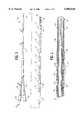
- FIG. 3is an elevational view of a guidewire embodying features of the invention.
- FIG. 4is an enlarged longitudinal cross-sectional view of a distal portion of the guidewire shown in FIG. 3.
- FIG. 5is an enlarged longitudinal cross-sectional view of a distal portion of a guidewire similar to that shown in FIG. 3 but with multiple braided layers in the shaft thereof.
- FIG. 6is a transverse cross-sectional view of a distal portion of the guidewire shown in FIG. 5 taken along the lines 6--6.
- FIG. 7is a longitudinal cross-sectional view of an intermediate portion of the guidewire shown in FIG. 3 taken along the lines 7--7.
- FIG. 8is a longitudinal cross-sectional view of the an extension of the proximal end of the guidewire shown in FIG. 3 taken along the lines 8--8.
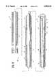
- FIG. 9is an elevational view, partially in section, of a catheter embodying features of the invention.
- FIG. 10is a transverse cross-sectional view of the catheter shown in FIG. 9 taken along the lines 10--10.
- FIG. 11is a longitudinal cross-sectional view of alternative guidewire suitable for use with the present invention.
- FIG. 12is an elevational view, partially in section, of a catheter system suitable for use with the present invention.
- FIG. 13is an enlarged elevational view, partially in section, of the distal portion of the catheter shown in FIG. 12.
- FIG. 14is a schematic view of a wave front passing on end is to a pair of intravascular sensing devices with a plurality of bipolar electrodes and the response from the passage of the wave front through each electrode pair.
- FIG. 15is a schematic view of a wave front emanating from a source between two intravascular sensing devices with a plurality of bipolar electrodes and the response from the passage of the wave front through each electrode pair.
- FIG. 1The presently preferred method of the invention is shown in FIG. 1 wherein a first elongated intravascular sensing device 10 is disposed within the right coronary artery 11 and a second elongated intravascular sensing device 12 is disposed within the anterior interventricular branch of the left coronary artery 13.
- the distal portion 14 of the first elongated intravascular device 10, having a plurality of electrodes 15,extends along a major portion of the right coronary artery 11
- the distal portion 16 of the second elongated intravascular sensing device 11, having a plurality of electrodes 17extends along a major portion of the anterior interventricular branch of the left coronary artery 13.
- the individual intravascular devices 10 and 12may be moved within the arteries as needed to optimize the signals received and particularly to detect with some precision the first onset of signals in question in order to more accurately pin point the source thereof.
- the intravascular sensing devices 10 and 12 as shownare in the form of guidewires which have shapable distal tips 18 and 19 to facilitate entry into side branches of the patient's epicardial blood vessels.
- FIG. 2Another method is depicted in FIG. 2 wherein one elongated intravascular sensing device 20 of the invention is disposed within the great cardiac vein 21 and another elongated intravascular sensing device 22 is disposed in the anterior interventricular branch of the left coronary artery 13.
- the intravascular sensing device 20has a plurality of electrodes 23 space along the distal portion 24 thereof and the intravascular sensing device 22 has a plurality of electrodes 25 space along it distal portion 26.
- a third intravascular sensing device 27might also be deployed within the right coronary artery 11 to provide for detection of electrical activity from a wider region of the patient's heart and to thereby facilitate more comprehensive mapping of the patient's heart.
- the individual steering devicesmay be moved within the arteries or veins to more accurately pinpoint the region from which the received electrical activity originates.
- FIGS. 3-8schematicly illustrate in greater detail an embodiment of the invention wherein the elongated sensing device is the form of a guidewire 40 which includes shaft 41 with a distal portion 42 and a proximal portion 43.
- the shaft 41is formed of a tubular member 44 formed of a plurality of braided or woven electrical conductors 45. While it is preferable that the conductors 45 be interwoven into the tubular member 44, they may be twisted or wound about a mandrel or the core member 48. In the latter case the inner and outer layers of wires would be laid out diagonally but the conductors of one layer would be laid in the opposite direction to that of the conductors in the other layer.
- the wound or twisted conductorsare secured together by suitable adhesive which makes the shaft relatively stiff, whereas with the interwoven conductors there is sufficient interlocking of the conductors that adhesives are not usually needed with the result of a more flexible shaft 41.
- the distal section 42 of the shaft 41is provided with a plurality of electrodes 46 which are preferably arranged as pairs 47 to facilitate a bipolar or multipolar mode of operation.
- the core member 48is disposed within the inner lumen of the braided tubular member 44 and extends beyond the distal end thereof.
- the distal end 49 of the core member 48is preferably flattened, as shown in FIG.
- the core member 48may be provided with one or more tapers 52 as with conventional guidewires.
- the proximal portion 43 of the shaft 41has two extensions 53 and 54 which have multi-pin connectors 55 and 56 on the proximal ends thereof with each of the electrical conductors 45 being electrically connected to a separate pin.
- FIG. 4illustrates the tubular member 44 formed of a single braided layer 57 with sixteen strands.
- a high number of electrical conductors 45e.g. more than 16
- a plurality of braided layersshould be employed, as depicted in FIG. 5.
- the outer braided layer 58terminates at a location proximal to that of the intermediate layer 59 and the intermediate layer terminates at a location proximal to the innermost layer 60 to facilitate securing and electrically connecting the electrodes 46 to the individual electrical conductors 45.
- Some of the strands in the layersmay be formed of nonconductive polymer materials such as Dacron, nylon or silk.
- proximal extension 56is depicted in FIG. 8. wherein an sixteen pin connector 58 is schematically shown, but connectors having a higher or lower number of pins have been found suitable.
- FIGS. 9 and 10schematically illustrate the embodiment of the invention in the form of a catheter 61.
- catheter shaft 62has an inner lumen 63 defined by an inner tubular element or lining 64 which is preferably formed of lubricous material such as fluoropolymers, e.g. Teflon® and polysulfones and hydrophilic polymers such as polyvinypyrrolidone, polyethylene oxide and acrylate-based polymers.
- a tubular member 65is disposed about tubular lining 64 and is formed of at least one braided layer 66.
- a plurality of the strands 67 making up each of the braided layersare insulated electrical conductors which are electrically connected to electrodes 68.
- the electrodes 68are preferably arranged in pairs 69 to facilitate bipolar mode operation. While not shown in the drawing, a plurality of braided layers may be desireable with more than eight electrode pairs 69. Some of the strands 67 in each of the layers may be formed of nonconducting materials such as nylon.
- An outer jacket 70extends the length of the shaft 62 and the portion of the jacket extending beyond the distal end of the braided tubular member 65 is tapered to provide a nontraumatic flexible distal tip 71. As in the previously described embodiments, the outer jacket 70 overlaps the edges of the electrodes 68 to avoid exposing a sharp metal edge when advancing the catheter through a patient's blood vessel.
- a guidewire 72(shown in phantom) is slidably disposed within the inner lumen 63.
- the catheter 61may also be used to direct diagnostic or therapeutic fluids to distal locations within a patients coronary vasculature.
- fluids containing cardioplegic materialssuch as iced saline, solutions of KCI, lidocaine, procaineamide hydrochloride and the like can be delivered to areas of the patient's heart which are suspected to be the origin of or conduct the aberrant signals. If the arrhythmia stops upon the delivery of the cardioplegic agent, then the operator is assured that the artery or vein through which the agent is delivered leads toward or away from the area of the patient's heart which needs to be ablated in order to terminate the arrhythmia.
- guiding cathetersWhen using an approach to the patient's heart through the femoral artery or femoral vein, it is frequently helpful to utilize one or more guiding catheters to guide the intravascular sensing devices of the invention to the coronary artery ostium or the coronary sinus ostium.
- Such guiding cathetersfrequently have specially shaped distal tips to facilitate the seating thereof within the desired coronary ostium or coronary sinus ostium.
- the use of guiding cathetereliminates the need to direct the distal tip of a catheter or a guidewire of the invention into the desire ostium.
- the electrodes on the distal portions of the sensing devicesare typically gold bands with widths of about 0.5 mm.
- the distance between the electrodes of an electrode pairis typically about 1 mm and the distance between electrode pairs is typically about 7-8 mm.
- the overall length of the intravascular devices of the inventiondepend upon the site of introduction into the patient's peripheral vasculature but may range from about 80 to about 300 cm, typically about 135 cm for delivery through the femoral artery or vein and about 90 cm for delivery through the brachiocephalic artery or internal jugular vein.
- the flexible distal portions of the intervascular sensing devicesare about 10 to about 50 cm in length and are configured to be readily advanceable through a patient's coronary arteries or cardiac veins.
- the outer diameter of the catheter form of the sensing deviceshould be less than about 0.055 inch (1.4 mm) and preferably about 0.035 inch (0.89 mm) and the inner lumen thereof is about 0.012 to about 0.022 inch (0.3-0.56 mm) in diameter to facilitate the reception and advancement of a guidewire therethrough.
- the distal portion of the guidewireis about 15 to about 40 cm in length and about 0.008 to about 0.022 inch (0.2-0.56 mm) in outer diameter to facilitate advancement through blood vessels having native diameters of less than 1 mm, frequently less than 0.75 mm.
- the distal coil on the guidewireis about 2 to about 10 cm in length and is formed of wire about 0.0003 to about 0.006 inch (0.0076-0.15 mm) in diameter. It is preferably formed of platinum to facilitate fluoroscopic observation thereof within the patient, but it may be formed in whole or in part with other material such as stainless steel titanium, palladium, niobium, iridium, rhodium and alloys thereof
- the materials of construction of the various guidewire and catheter partsmay be formed of conventional materials.
- the electrical conductorsmay be electrical grade copper wire about 0.005 inch (0.127 mm) in diameter which are provided with a thin insulated jacket or coating of polyimide or other suitable insulator.
- the outer jacketmay be a thermoplastic fluoropolymer such as THV which is available from 3M Corporation.
- the core wire of the guidewiremay be formed of stainless steel or a superelastic NiTi type alloy, the latter exhibiting a stable austenite phase at body temperature.
- the NiTi alloyexhibits a stress induced transformation from the stable austenite to a lower strength martensite phase. Upon release of the stress, the alloy returns to the austenite phase.
- Proximal and distal sections of the core membermay be formed of different materials so as to provide a stronger proximal section for greater pushability and a more flexible distal section to facilitate passage through tortuous coronary anatomy. Manufacturing techniques used in making catheters and guidewires for angioplasty procedures may be used in the making of the intravascular devices of the invention.
- An alternative embodiment of the invention in the form of a guidewire 80is shown in FIG. 11 which is similar to that shown in FIGS. 3-8 except that only a single pair of electrodes 81 and 82 are shown on distal portion 83.
- the shaft 84has a proximal portion 85 which is formed in part of a hypotube 86.
- a core member 87extends through the inner lumen of the hypotube 86 and is electrically isolated from the hypotube 86 by insulating jacket 88.
- the distal portion of the core member 87extends out the distal end of the hypotube 86 as indicated in the drawing.
- the distal electrode 82is electrically secured to the core member 87 by solder 89 and the proximal electrode 81 is secured by solder 90 to electrical conductor 91 which may be an insulated wire or ribbon.
- the proximal end of the electrical conductor 91is secured by solder 92 to the hypotube 86 which is formed of electrically conductive metal (stainless steel).
- the exterior surface of the conductive metal tube 86should be provided with an insulating jacket or coating 93.
- the core member 87 and the conductive metal tube 86are preferably secured together at one or more locations by an insulating adhesive to facilitate the torqueability of the overall guidewire shaft. Preferably, they are secured at least at the distal end of the metal tube
- a coil 94is disposed about the distal portion of the core member 87 proximal to the proximal electrode 81 and it is secured to the core member by a suitable means 95. Such securing may be effected by soldering, brazing, welding or suitable adhesive depending upon the materials from which the coil 94 and the core member 87 are made.
- the core member 87 and the coil 94provide shapeability to the distal portion 83 of the guidewire 80 to facilitate its advancement into side branches of a patient's vasculature.
- An inner tubular member 96may be disposed within the coil 94 in the distal section 83 to provide support to the electrode 81 and inner tubular member 97 may be disposed within the coil 94 to likewise provide support thereto to electrode 82.
- a suitable materialis thin walled polyimide tubing which is frequently mentioned as being suitable for use in intravascular catheters.
- FIGS. 12 and 13illustrate a catheter assembly 100 which embodies an additional aspect of the present invention directed to an intravascular catheter 101 for sensing electrical activity within a patient's coronary or cardiac blood vessels.
- electrodes 102are electrically connected to individual electrical conductors 103 which are woven or wound to form the tubular shaft 104 of the catheter 101. All of the strands which are wound to form the shaft 104 need not be conductors 103 as in the prior embodiments, and when there are more than 16 electrodes and thus more than 16 electrical conductors, multiple woven layers may be employed.
- the electrical conductors 103are typically electrical grade copper wires of suitable outer diameter such as about 0.004 to about 0.01 inch (0.10-0.25 mm).
- the conductors 103may be formed of other conducting materials such as silver, gold and platinum.
- a suitable insulating material to coat the conductors 103is polyimide which minimizes cross talk and which can be applied in very thin layers.
- the conductors 103may be woven or merely wound, but preferably are woven.
- the inner lumen 105 of the catheter 100is configured to slidably receive a guidewire to facilitate the advancement of the catheter over the guidewire and preferably has at least in the distal portion thereof a diameter about 0.002 to about 0.005 inch (0.051-0.127 mm) greater than the guidewire which is to be disposed therein.
- the inner lumen 97would be about 0.018 to about 0.023 inch (0.46-0.58 mm).
- the OD of the cathetermay range from about 0.03 to about 0.1 inch (0.76-2.54 mm) but preferably is about 0.03 to about 0.05 inch (0.076-1.27 mm, particularly 0.035 to about 0.040 inch (0.89-1.02 mm).
- the proximal portion 106 of the catheter 100makes up about 70 to about 95% of the total length of the catheter with the intermediate portion 107 and the distal portion 108 which has the sensing electrodes 102 being the remainder.
- the catheter 100has decreasing stiffness from the proximal portion 106 to the intermediate portion 107 and the distal portion 108 to facilitate the advancement of the catheter 100 within the patient's vasculature.
- the exterior surface of the catheter 100 and the surface defining inner lumen 105are formed of lubricous materials or hydrophilic materials which become lubricous when contacting aqueous based fluids. Polysulfones and polyfluoroalkanes are examples of suitable lubricous polymers and polyvinypyrrolidone, polyethylene oxide and acrylate-based polymers of examples of suitable hydrophilic polymers.
- the proximal end of the catheter 106may be provided with a multiple arm adapter 109 as shown in FIG. 12 with one arm 110 which is configured to receive a syringe for delivering fluid into the inner lumen and a second arm 111 which is provided with an electrical connector 112 which is electrically connected to the electrical conductors 103.
- the central arm 112facilitates entry of a guidewire (not shown) into the inner lumen 105.
- the guidewiremay be removed and means can be advanced through the inner lumen 105 of a catheter of the invention to occlude an arterial passageway which feeds the arrhythmogenic site or conductive pathway so as to terminate the arrhythmia.
- FIG. 14schematically represents the output from a plurality of electrode pairs 120 and 121 on separate intravascular devices (not shown) disposed in different, generally parallel coronary blood vessels, e.g. a coronary artery and the companion vein to a nearly planar wave front approaching on end to the intravascular devices.
- the bipolar response 122 and 123 to the wave front 124 from each electrode pairis shown adjacent thereto, and as indicated, all of the responses are essentially identical except for the time-of-occurence, because the wave front 124 reaches all of the electrodes at the same angle. Changes in tissue properties adjacent the catheters may retard the passage of the wave front and may distort the shape of the output.
- FIG. 15schematically represents the responses 130 and 131 from a plurality of electrode pairs 132 and 133 on separate intravascular devices (not shown) disposed in different generally parallel coronary blood vessels, as in FIG. 14, but the wave front 134 originates from an arrhythmogenic site between and in close proximity to the catheters.
- the wave front 134is circular (idealized) and the size and polarity of the responses to the expanding wave front varies according to the angle of incidence.
- the time of occurrence and the directional information in the aforementioned schematic drawingsmay be used to determine the origin of the ectopic beat.
Landscapes
- Health & Medical Sciences (AREA)
- Life Sciences & Earth Sciences (AREA)
- Surgery (AREA)
- Veterinary Medicine (AREA)
- Public Health (AREA)
- General Health & Medical Sciences (AREA)
- Animal Behavior & Ethology (AREA)
- Engineering & Computer Science (AREA)
- Biomedical Technology (AREA)
- Heart & Thoracic Surgery (AREA)
- Medical Informatics (AREA)
- Molecular Biology (AREA)
- Pathology (AREA)
- Biophysics (AREA)
- Physics & Mathematics (AREA)
- Cardiology (AREA)
- Physiology (AREA)
- Reproductive Health (AREA)
- Vascular Medicine (AREA)
- Nuclear Medicine, Radiotherapy & Molecular Imaging (AREA)
- Measurement And Recording Of Electrical Phenomena And Electrical Characteristics Of The Living Body (AREA)
- Measuring Pulse, Heart Rate, Blood Pressure Or Blood Flow (AREA)
- Measurement Of The Respiration, Hearing Ability, Form, And Blood Characteristics Of Living Organisms (AREA)
- Measuring Or Testing Involving Enzymes Or Micro-Organisms (AREA)
Abstract
Description
Claims (40)
Priority Applications (1)
| Application Number | Priority Date | Filing Date | Title |
|---|---|---|---|
| US09/006,542US6088610A (en) | 1993-01-29 | 1998-01-13 | Method and system for using multiple intravascular sensing devices to detect electrical activity |
Applications Claiming Priority (5)
| Application Number | Priority Date | Filing Date | Title |
|---|---|---|---|
| US1081893A | 1993-01-29 | 1993-01-29 | |
| US4344993A | 1993-04-05 | 1993-04-05 | |
| US5729493A | 1993-05-05 | 1993-05-05 | |
| US08/188,298US5706809A (en) | 1993-01-29 | 1994-01-27 | Method and system for using multiple intravascular sensing devices to detect electrical activity |
| US09/006,542US6088610A (en) | 1993-01-29 | 1998-01-13 | Method and system for using multiple intravascular sensing devices to detect electrical activity |
Related Parent Applications (2)
| Application Number | Title | Priority Date | Filing Date |
|---|---|---|---|
| US1081893AContinuation-In-Part | 1993-01-29 | 1993-01-29 | |
| US08/188,298ContinuationUS5706809A (en) | 1993-01-29 | 1994-01-27 | Method and system for using multiple intravascular sensing devices to detect electrical activity |
Publications (1)
| Publication Number | Publication Date |
|---|---|
| US6088610Atrue US6088610A (en) | 2000-07-11 |
Family
ID=27486036
Family Applications (1)
| Application Number | Title | Priority Date | Filing Date |
|---|---|---|---|
| US09/006,542Expired - LifetimeUS6088610A (en) | 1993-01-29 | 1998-01-13 | Method and system for using multiple intravascular sensing devices to detect electrical activity |
Country Status (9)
| Country | Link |
|---|---|
| US (1) | US6088610A (en) |
| EP (1) | EP0681451B1 (en) |
| AT (1) | ATE205066T1 (en) |
| AU (3) | AU5966398A (en) |
| CA (1) | CA2154774C (en) |
| DE (1) | DE69428188T2 (en) |
| DK (1) | DK0681451T3 (en) |
| ES (1) | ES2163436T3 (en) |
| PT (1) | PT681451E (en) |
Cited By (31)
| Publication number | Priority date | Publication date | Assignee | Title |
|---|---|---|---|---|
| US20040097819A1 (en)* | 2002-11-15 | 2004-05-20 | Duarte Maria J. | Telescoping catheter |
| US6771996B2 (en)* | 2001-05-24 | 2004-08-03 | Cardiac Pacemakers, Inc. | Ablation and high-resolution mapping catheter system for pulmonary vein foci elimination |
| US20040209692A1 (en)* | 2003-04-17 | 2004-10-21 | Grips Elektronik G.M.B.H. | Player insert for a gaming machine, a gaming system and a method of operating a gaming system |
| US20040249417A1 (en)* | 2003-06-04 | 2004-12-09 | Terrance Ransbury | Implantable intravascular device for defibrillation and/or pacing |
| US7025716B1 (en)* | 1996-09-23 | 2006-04-11 | Novoste Corporation | Intraluminal radiation treatment system |
| US20070083193A1 (en)* | 2005-08-22 | 2007-04-12 | Werneth Randell L | User interface for tissue ablation system |
| US20070106293A1 (en)* | 2002-10-25 | 2007-05-10 | Hakan Oral | Ablation catheters |
| US20070167696A1 (en)* | 2002-05-13 | 2007-07-19 | Cathrx Pty Ltd | Multi-electrode lead |
| US20070265673A1 (en)* | 2006-04-03 | 2007-11-15 | Terrance Ransbury | Flexible interconnect assembly for implantable medical devices |
| US20080161803A1 (en)* | 2002-10-25 | 2008-07-03 | The Regents Of The University Of Michigan | Ablation Catheters And Methods For Their Use |
| US7429261B2 (en) | 2004-11-24 | 2008-09-30 | Ablation Frontiers, Inc. | Atrial ablation catheter and method of use |
| US7468062B2 (en) | 2004-11-24 | 2008-12-23 | Ablation Frontiers, Inc. | Atrial ablation catheter adapted for treatment of septal wall arrhythmogenic foci and method of use |
| US7529589B2 (en) | 2003-06-04 | 2009-05-05 | Synecor Llc | Intravascular electrophysiological system and methods |
| US7617007B2 (en) | 2003-06-04 | 2009-11-10 | Synecor Llc | Method and apparatus for retaining medical implants within body vessels |
| US7747335B2 (en) | 2003-12-12 | 2010-06-29 | Synecor Llc | Implantable medical device having pre-implant exoskeleton |
| US7850685B2 (en) | 2005-06-20 | 2010-12-14 | Medtronic Ablation Frontiers Llc | Ablation catheter |
| US20110190756A1 (en)* | 2008-01-09 | 2011-08-04 | Mayo Foundation For Medical Education And Research | Mapping and ablation catheter system |
| US8239045B2 (en) | 2003-06-04 | 2012-08-07 | Synecor Llc | Device and method for retaining a medical device within a vessel |
| US20130090648A1 (en)* | 2011-10-07 | 2013-04-11 | Boston Scientific Scimed, Inc. | Methods and systems for detection and thermal treatment of lower urinary tract conditions |
| US8486063B2 (en) | 2004-10-14 | 2013-07-16 | Medtronic Ablation Frontiers Llc | Ablation catheter |
| US8617152B2 (en) | 2004-11-15 | 2013-12-31 | Medtronic Ablation Frontiers Llc | Ablation system with feedback |
| US8641704B2 (en) | 2007-05-11 | 2014-02-04 | Medtronic Ablation Frontiers Llc | Ablation therapy system and method for treating continuous atrial fibrillation |
| US8834461B2 (en) | 2005-07-11 | 2014-09-16 | Medtronic Ablation Frontiers Llc | Low power tissue ablation system |
| US9089350B2 (en) | 2010-11-16 | 2015-07-28 | Boston Scientific Scimed, Inc. | Renal denervation catheter with RF electrode and integral contrast dye injection arrangement |
| EP2915498A1 (en)* | 2014-03-05 | 2015-09-09 | Biosense Webster (Israel), Ltd. | Multi-arm catheter with signal transmission over braid wires |
| US9492113B2 (en) | 2011-07-15 | 2016-11-15 | Boston Scientific Scimed, Inc. | Systems and methods for monitoring organ activity |
| US9615760B2 (en) | 2013-06-17 | 2017-04-11 | Biosense Webster (Israel), Ltd. | Multiple bipolar sampling |
| US20200129231A1 (en)* | 2018-10-25 | 2020-04-30 | Medtronic Vascular, Inc. | Cavitation guidewire |
| US10675462B2 (en) | 2015-11-04 | 2020-06-09 | Boston Scientific Scimed, Inc. | Medical device and related methods |
| US11266425B2 (en) | 2018-10-25 | 2022-03-08 | Medtronic Vascular, Inc. | Cavitation catheter |
| CN118284365A (en)* | 2021-12-09 | 2024-07-02 | 株式会社爱普森医疗 | Information processing device for epilepsy diagnosis, intravascular device, information processing method for epilepsy diagnosis, and computer program for epilepsy diagnosis |
Citations (50)
| Publication number | Priority date | Publication date | Assignee | Title |
|---|---|---|---|---|
| US33925A (en)* | 1861-12-17 | Improvement in fastenings for shoulder-straps | ||
| US452220A (en)* | 1891-05-12 | gunning | ||
| DE1813232A1 (en)* | 1967-12-15 | 1969-06-26 | Lorraine Carbone | Electrical conductor for electrosystolic stimulators |
| DE2605590A1 (en)* | 1976-02-12 | 1977-08-18 | Heinz Dr Med Praeuer | Pacemaker electrode with flexible electrode catheter - with flexible projecting base for abutment against wall of heart |
| WO1980002801A1 (en)* | 1979-06-14 | 1980-12-24 | B Reenstierna | Endocardial,implantable lead for pacemaker |
| US4271847A (en)* | 1979-06-28 | 1981-06-09 | Medtronic, Inc. | Temporary adjustable bipolar lead |
| US4402330A (en)* | 1979-09-24 | 1983-09-06 | Medtronic, Inc. | Body implantable lead |
| US4437474A (en)* | 1982-07-16 | 1984-03-20 | Cordis Corporation | Method for making multiconductor coil and the coil made thereby |
| US4458677A (en)* | 1979-09-19 | 1984-07-10 | Mccorkle Jr Charles E | Intravenous channel cardiac electrode and lead assembly and method |
| US4467817A (en)* | 1981-04-20 | 1984-08-28 | Cordis Corporation | Small diameter lead with introducing assembly |
| US4481953A (en)* | 1981-11-12 | 1984-11-13 | Cordis Corporation | Endocardial lead having helically wound ribbon electrode |
| US4559951A (en)* | 1982-11-29 | 1985-12-24 | Cardiac Pacemakers, Inc. | Catheter assembly |
| US4690155A (en)* | 1985-07-03 | 1987-09-01 | Cordis Corporation | Monophasic action potential recording lead |
| US4759378A (en)* | 1982-10-14 | 1988-07-26 | American Hospital Supply Corporation | Flexible tip cardiac pacing catheter |
| US4777955A (en)* | 1987-11-02 | 1988-10-18 | Cordis Corporation | Left ventricle mapping probe |
| US4785815A (en)* | 1985-10-23 | 1988-11-22 | Cordis Corporation | Apparatus for locating and ablating cardiac conduction pathways |
| EP0293499A1 (en)* | 1987-06-01 | 1988-12-07 | Siemens-Elema AB | Implantable multi-pole coaxial lead |
| DE3718139C1 (en)* | 1987-05-29 | 1988-12-08 | Strahlen Umweltforsch Gmbh | Cardiac catheter |
| US4867173A (en)* | 1986-06-30 | 1989-09-19 | Meadox Surgimed A/S | Steerable guidewire |
| US4869248A (en)* | 1987-04-17 | 1989-09-26 | Narula Onkar S | Method and apparatus for localized thermal ablation |
| WO1990003151A1 (en)* | 1988-09-23 | 1990-04-05 | Brigham And Women's Hospital | Cryoablation catheter and method of performing cryoablation |
| US4945912A (en)* | 1988-11-25 | 1990-08-07 | Sensor Electronics, Inc. | Catheter with radiofrequency heating applicator |
| US4957110A (en)* | 1989-03-17 | 1990-09-18 | C. R. Bard, Inc. | Steerable guidewire having electrodes for measuring vessel cross-section and blood flow |
| US4966597A (en)* | 1988-11-04 | 1990-10-30 | Cosman Eric R | Thermometric cardiac tissue ablation electrode with ultra-sensitive temperature detection |
| US4979510A (en)* | 1984-03-06 | 1990-12-25 | Ep Technologies, Inc. | Apparatus and method for recording monophasic action potentials from an in vivo heart |
| US5029585A (en)* | 1989-07-14 | 1991-07-09 | Baxter International Inc. | Comformable intralumen electrodes |
| US5044375A (en)* | 1989-12-08 | 1991-09-03 | Cardiac Pacemakers, Inc. | Unitary intravascular defibrillating catheter with separate bipolar sensing |
| US5083565A (en)* | 1990-08-03 | 1992-01-28 | Everest Medical Corporation | Electrosurgical instrument for ablating endocardial tissue |
| US5095916A (en)* | 1985-06-20 | 1992-03-17 | Medtronic, Inc. | Cardioversion and defibrillation lead system |
| US5095917A (en)* | 1990-01-19 | 1992-03-17 | Vancaillie Thierry G | Transuterine sterilization apparatus and method |
| US5099838A (en)* | 1988-12-15 | 1992-03-31 | Medtronic, Inc. | Endocardial defibrillation electrode system |
| USRE33925E (en) | 1984-05-22 | 1992-05-12 | Cordis Corporation | Electrosurgical catheter aned method for vascular applications |
| US5122136A (en)* | 1990-03-13 | 1992-06-16 | The Regents Of The University Of California | Endovascular electrolytically detachable guidewire tip for the electroformation of thrombus in arteries, veins, aneurysms, vascular malformations and arteriovenous fistulas |
| US5125896A (en)* | 1990-10-10 | 1992-06-30 | C. R. Bard, Inc. | Steerable electrode catheter |
| US5140987A (en)* | 1989-03-17 | 1992-08-25 | Wayne State University | Method for transvenous ablation of cardiac electrically conductive tissue by laser photocoagulation |
| US5163445A (en)* | 1987-04-10 | 1992-11-17 | Cardiometrics, Inc. | Apparatus, system and method for measuring spatial average velocity and/or volumetric flow of blood in a vessel and screw joint for use therewith |
| US5165403A (en)* | 1991-02-26 | 1992-11-24 | Medtronic, Inc. | Difibrillation lead system and method of use |
| WO1992021278A1 (en)* | 1991-05-24 | 1992-12-10 | Ep Technologies, Inc. | Combination monophasic action potential/ablation catheter and high-performance filter system |
| US5170802A (en)* | 1991-01-07 | 1992-12-15 | Medtronic, Inc. | Implantable electrode for location within a blood vessel |
| US5174288A (en)* | 1990-11-30 | 1992-12-29 | Medtronic, Inc. | Method and apparatus for cardiac defibrillation |
| US5184621A (en)* | 1991-05-29 | 1993-02-09 | C. R. Bard, Inc. | Steerable guidewire having electrodes for measuring vessel cross-section and blood flow |
| US5193550A (en)* | 1990-11-30 | 1993-03-16 | Medtronic, Inc. | Method and apparatus for discriminating among normal and pathological tachyarrhythmias |
| US5193546A (en)* | 1991-05-15 | 1993-03-16 | Alexander Shaknovich | Coronary intravascular ultrasound imaging method and apparatus |
| WO1994006349A1 (en)* | 1992-09-23 | 1994-03-31 | Endocardial Therapeutics, Inc. | Endocardial mapping system |
| US5330522A (en)* | 1992-12-29 | 1994-07-19 | Siemens Pacesetter, Inc. | Ring electrode for a multilumen lead and method of constructing a multilumen lead |
| US5500012A (en)* | 1992-07-15 | 1996-03-19 | Angeion Corporation | Ablation catheter system |
| US5509411A (en)* | 1993-01-29 | 1996-04-23 | Cardima, Inc. | Intravascular sensing device |
| US5545204A (en)* | 1993-03-08 | 1996-08-13 | Cammilli; Leonardo | Sequential cardiostimulation system (DDD) using a single electrocatheter inserted through the coronary sinus |
| US5549109A (en)* | 1993-10-01 | 1996-08-27 | Target Therapeutics, Inc. | Sheathed multipolar catheter and multipolar guidewire for sensing cardiac electrical activity |
| US5741214A (en)* | 1993-12-20 | 1998-04-21 | Terumo Kabushiki Kaisha | Accessory pathway detecting/cauterizing apparatus |
- 1994
- 1994-01-28DKDK94909513Tpatent/DK0681451T3/enactive
- 1994-01-28CACA002154774Apatent/CA2154774C/ennot_activeExpired - Fee Related
- 1994-01-28PTPT94909513Tpatent/PT681451E/enunknown
- 1994-01-28ESES94909513Tpatent/ES2163436T3/ennot_activeExpired - Lifetime
- 1994-01-28EPEP94909513Apatent/EP0681451B1/ennot_activeExpired - Lifetime
- 1994-01-28DEDE69428188Tpatent/DE69428188T2/ennot_activeExpired - Lifetime
- 1994-01-28ATAT94909513Tpatent/ATE205066T1/ennot_activeIP Right Cessation
- 1998
- 1998-01-13USUS09/006,542patent/US6088610A/ennot_activeExpired - Lifetime
- 1998-03-26AUAU59663/98Apatent/AU5966398A/ennot_activeAbandoned
- 1998-06-30AUAU73960/98Apatent/AU7396098A/ennot_activeAbandoned
- 1998-07-03AUAU74172/98Apatent/AU7417298A/ennot_activeAbandoned
Patent Citations (52)
| Publication number | Priority date | Publication date | Assignee | Title |
|---|---|---|---|---|
| US33925A (en)* | 1861-12-17 | Improvement in fastenings for shoulder-straps | ||
| US452220A (en)* | 1891-05-12 | gunning | ||
| DE1813232A1 (en)* | 1967-12-15 | 1969-06-26 | Lorraine Carbone | Electrical conductor for electrosystolic stimulators |
| DE2605590A1 (en)* | 1976-02-12 | 1977-08-18 | Heinz Dr Med Praeuer | Pacemaker electrode with flexible electrode catheter - with flexible projecting base for abutment against wall of heart |
| WO1980002801A1 (en)* | 1979-06-14 | 1980-12-24 | B Reenstierna | Endocardial,implantable lead for pacemaker |
| US4271847A (en)* | 1979-06-28 | 1981-06-09 | Medtronic, Inc. | Temporary adjustable bipolar lead |
| US4458677A (en)* | 1979-09-19 | 1984-07-10 | Mccorkle Jr Charles E | Intravenous channel cardiac electrode and lead assembly and method |
| US4402330A (en)* | 1979-09-24 | 1983-09-06 | Medtronic, Inc. | Body implantable lead |
| US4467817A (en)* | 1981-04-20 | 1984-08-28 | Cordis Corporation | Small diameter lead with introducing assembly |
| US4481953A (en)* | 1981-11-12 | 1984-11-13 | Cordis Corporation | Endocardial lead having helically wound ribbon electrode |
| US4437474A (en)* | 1982-07-16 | 1984-03-20 | Cordis Corporation | Method for making multiconductor coil and the coil made thereby |
| US4759378A (en)* | 1982-10-14 | 1988-07-26 | American Hospital Supply Corporation | Flexible tip cardiac pacing catheter |
| US4559951A (en)* | 1982-11-29 | 1985-12-24 | Cardiac Pacemakers, Inc. | Catheter assembly |
| US4979510A (en)* | 1984-03-06 | 1990-12-25 | Ep Technologies, Inc. | Apparatus and method for recording monophasic action potentials from an in vivo heart |
| USRE33925E (en) | 1984-05-22 | 1992-05-12 | Cordis Corporation | Electrosurgical catheter aned method for vascular applications |
| US5095916A (en)* | 1985-06-20 | 1992-03-17 | Medtronic, Inc. | Cardioversion and defibrillation lead system |
| US4690155A (en)* | 1985-07-03 | 1987-09-01 | Cordis Corporation | Monophasic action potential recording lead |
| US4785815A (en)* | 1985-10-23 | 1988-11-22 | Cordis Corporation | Apparatus for locating and ablating cardiac conduction pathways |
| US4867173A (en)* | 1986-06-30 | 1989-09-19 | Meadox Surgimed A/S | Steerable guidewire |
| US5163445A (en)* | 1987-04-10 | 1992-11-17 | Cardiometrics, Inc. | Apparatus, system and method for measuring spatial average velocity and/or volumetric flow of blood in a vessel and screw joint for use therewith |
| US4869248A (en)* | 1987-04-17 | 1989-09-26 | Narula Onkar S | Method and apparatus for localized thermal ablation |
| DE3718139C1 (en)* | 1987-05-29 | 1988-12-08 | Strahlen Umweltforsch Gmbh | Cardiac catheter |
| US4840186A (en)* | 1987-06-01 | 1989-06-20 | Siemens Aktiengesellschaft | Implantable multi-pole coaxial lead |
| EP0293499A1 (en)* | 1987-06-01 | 1988-12-07 | Siemens-Elema AB | Implantable multi-pole coaxial lead |
| US4777955A (en)* | 1987-11-02 | 1988-10-18 | Cordis Corporation | Left ventricle mapping probe |
| WO1990003151A1 (en)* | 1988-09-23 | 1990-04-05 | Brigham And Women's Hospital | Cryoablation catheter and method of performing cryoablation |
| US4966597A (en)* | 1988-11-04 | 1990-10-30 | Cosman Eric R | Thermometric cardiac tissue ablation electrode with ultra-sensitive temperature detection |
| US4945912A (en)* | 1988-11-25 | 1990-08-07 | Sensor Electronics, Inc. | Catheter with radiofrequency heating applicator |
| US5099838A (en)* | 1988-12-15 | 1992-03-31 | Medtronic, Inc. | Endocardial defibrillation electrode system |
| US4957110A (en)* | 1989-03-17 | 1990-09-18 | C. R. Bard, Inc. | Steerable guidewire having electrodes for measuring vessel cross-section and blood flow |
| US5140987A (en)* | 1989-03-17 | 1992-08-25 | Wayne State University | Method for transvenous ablation of cardiac electrically conductive tissue by laser photocoagulation |
| US5029585A (en)* | 1989-07-14 | 1991-07-09 | Baxter International Inc. | Comformable intralumen electrodes |
| US5044375A (en)* | 1989-12-08 | 1991-09-03 | Cardiac Pacemakers, Inc. | Unitary intravascular defibrillating catheter with separate bipolar sensing |
| US5095917A (en)* | 1990-01-19 | 1992-03-17 | Vancaillie Thierry G | Transuterine sterilization apparatus and method |
| US5122136A (en)* | 1990-03-13 | 1992-06-16 | The Regents Of The University Of California | Endovascular electrolytically detachable guidewire tip for the electroformation of thrombus in arteries, veins, aneurysms, vascular malformations and arteriovenous fistulas |
| US5083565A (en)* | 1990-08-03 | 1992-01-28 | Everest Medical Corporation | Electrosurgical instrument for ablating endocardial tissue |
| US5125896A (en)* | 1990-10-10 | 1992-06-30 | C. R. Bard, Inc. | Steerable electrode catheter |
| US5174288A (en)* | 1990-11-30 | 1992-12-29 | Medtronic, Inc. | Method and apparatus for cardiac defibrillation |
| US5193550A (en)* | 1990-11-30 | 1993-03-16 | Medtronic, Inc. | Method and apparatus for discriminating among normal and pathological tachyarrhythmias |
| US5170802A (en)* | 1991-01-07 | 1992-12-15 | Medtronic, Inc. | Implantable electrode for location within a blood vessel |
| US5165403A (en)* | 1991-02-26 | 1992-11-24 | Medtronic, Inc. | Difibrillation lead system and method of use |
| US5193546A (en)* | 1991-05-15 | 1993-03-16 | Alexander Shaknovich | Coronary intravascular ultrasound imaging method and apparatus |
| WO1992021278A1 (en)* | 1991-05-24 | 1992-12-10 | Ep Technologies, Inc. | Combination monophasic action potential/ablation catheter and high-performance filter system |
| US5184621A (en)* | 1991-05-29 | 1993-02-09 | C. R. Bard, Inc. | Steerable guidewire having electrodes for measuring vessel cross-section and blood flow |
| US5500012A (en)* | 1992-07-15 | 1996-03-19 | Angeion Corporation | Ablation catheter system |
| WO1994006349A1 (en)* | 1992-09-23 | 1994-03-31 | Endocardial Therapeutics, Inc. | Endocardial mapping system |
| US5330522A (en)* | 1992-12-29 | 1994-07-19 | Siemens Pacesetter, Inc. | Ring electrode for a multilumen lead and method of constructing a multilumen lead |
| US5509411A (en)* | 1993-01-29 | 1996-04-23 | Cardima, Inc. | Intravascular sensing device |
| US5706809A (en)* | 1993-01-29 | 1998-01-13 | Cardima, Inc. | Method and system for using multiple intravascular sensing devices to detect electrical activity |
| US5545204A (en)* | 1993-03-08 | 1996-08-13 | Cammilli; Leonardo | Sequential cardiostimulation system (DDD) using a single electrocatheter inserted through the coronary sinus |
| US5549109A (en)* | 1993-10-01 | 1996-08-27 | Target Therapeutics, Inc. | Sheathed multipolar catheter and multipolar guidewire for sensing cardiac electrical activity |
| US5741214A (en)* | 1993-12-20 | 1998-04-21 | Terumo Kabushiki Kaisha | Accessory pathway detecting/cauterizing apparatus |
Non-Patent Citations (15)
| Title |
|---|
| Brugada et al. "Termination o Tachycardias by Interrupting Blood Flow to the Arrhythmogenic Area" Am. J. Cardiology 62:387-392 (1988). |
| Brugada et al. "Transcordary Chemical Ablation of Ventricular Tachycardia" Circulation 79:475-482 (1989). |
| Brugada et al. Termination o Tachycardias by Interrupting Blood Flow to the Arrhythmogenic Area Am. J. Cardiology 62:387 392 (1988).* |
| Brugada et al. Transcordary Chemical Ablation of Ventricular Tachycardia Circulation 79:475 482 (1989).* |
| Fisher et al. "Nonsurgical Electrical Ablation of Tachycardias: Importance of Prior in Vitro Testing of Catheter Leads" PACE 7:74-81 (1984). |
| Fisher et al. Nonsurgical Electrical Ablation of Tachycardias: Importance of Prior in Vitro Testing of Catheter Leads PACE 7 :74 81 (1984).* |
| Lawrence T. Weston, M.D. et al. "A Prototype Coronary Electrode Catheter for Intracoronary Electrogram Recording" The American Journal of Cardiology 70:1492-1493 (Dec. 1992). |
| Lawrence T. Weston, M.D. et al. A Prototype Coronary Electrode Catheter for Intracoronary Electrogram Recording The American Journal of Cardiology 70:1492 1493 (Dec. 1992).* |
| Lesh, M.D. et al. "Mapping in the Right Coronary Artery as an Aid to Radiofrequency ablation of Right-Sided Accessory Pathways" NASPE Abstracts PACE, 14(213):671 Part II (Apr. 1991). |
| Lesh, M.D. et al. Mapping in the Right Coronary Artery as an Aid to Radiofrequency ablation of Right Sided Accessory Pathways NASPE Abstracts PACE, 14(213):671 Part II (Apr. 1991).* |
| Repetto et al. "Transcoronary Epicardial Mapping of Accessory Pathways. Implications for Ablation Techniques. 10th Int'l Cong."The New Frontiers of Arrhythmias Marilleva, Italy pp 475-480 (Jan. 1992). |
| Repetto et al. Transcoronary Epicardial Mapping of Accessory Pathways. Implications for Ablation Techniques. 10th Int l Cong. The New Frontiers of Arrhythmias Marilleva, Italy pp 475 480 (Jan. 1992).* |
| Swartz, M.D. et al. Endocardial Atrial Catheter Ablation of Accessory Pathways After Intravascular Localization NASPE Abstracts, PACE 13(126):527 (Apr. 1990).* |
| Walter et al. Europ. Surg. Res. 3:130 138 (1971).* |
| Walter et al. Europ. Surg. Res. 3:130-138 (1971). |
Cited By (64)
| Publication number | Priority date | Publication date | Assignee | Title |
|---|---|---|---|---|
| US7025716B1 (en)* | 1996-09-23 | 2006-04-11 | Novoste Corporation | Intraluminal radiation treatment system |
| US6771996B2 (en)* | 2001-05-24 | 2004-08-03 | Cardiac Pacemakers, Inc. | Ablation and high-resolution mapping catheter system for pulmonary vein foci elimination |
| US20070167696A1 (en)* | 2002-05-13 | 2007-07-19 | Cathrx Pty Ltd | Multi-electrode lead |
| US7967817B2 (en)* | 2002-05-13 | 2011-06-28 | Cathrx Ltd. | Multi-electrode lead |
| US20080269738A1 (en)* | 2002-05-13 | 2008-10-30 | Anderson Neil L | Multi-electrode lead |
| US7415300B2 (en)* | 2002-05-13 | 2008-08-19 | Cathrx Ltd. | Multi-electrode lead |
| EP1503667A4 (en)* | 2002-05-13 | 2009-05-13 | Cathrx Ltd | A multi-electrode lead |
| US7993333B2 (en) | 2002-10-25 | 2011-08-09 | The Regents Of The University Of Michigan | Ablation catheters |
| US7857808B2 (en) | 2002-10-25 | 2010-12-28 | The Regents Of The University Of Michigan | Ablation catheters |
| US20070106293A1 (en)* | 2002-10-25 | 2007-05-10 | Hakan Oral | Ablation catheters |
| US20080161803A1 (en)* | 2002-10-25 | 2008-07-03 | The Regents Of The University Of Michigan | Ablation Catheters And Methods For Their Use |
| US7039450B2 (en)* | 2002-11-15 | 2006-05-02 | Biosense Webster, Inc. | Telescoping catheter |
| US20040097819A1 (en)* | 2002-11-15 | 2004-05-20 | Duarte Maria J. | Telescoping catheter |
| US20040209692A1 (en)* | 2003-04-17 | 2004-10-21 | Grips Elektronik G.M.B.H. | Player insert for a gaming machine, a gaming system and a method of operating a gaming system |
| US7529589B2 (en) | 2003-06-04 | 2009-05-05 | Synecor Llc | Intravascular electrophysiological system and methods |
| US7899554B2 (en) | 2003-06-04 | 2011-03-01 | Synecor Llc | Intravascular System and Method |
| US8239045B2 (en) | 2003-06-04 | 2012-08-07 | Synecor Llc | Device and method for retaining a medical device within a vessel |
| US20040249417A1 (en)* | 2003-06-04 | 2004-12-09 | Terrance Ransbury | Implantable intravascular device for defibrillation and/or pacing |
| US7617007B2 (en) | 2003-06-04 | 2009-11-10 | Synecor Llc | Method and apparatus for retaining medical implants within body vessels |
| US7734343B2 (en) | 2003-06-04 | 2010-06-08 | Synecor, Llc | Implantable intravascular device for defibrillation and/or pacing |
| US7082336B2 (en) | 2003-06-04 | 2006-07-25 | Synecor, Llc | Implantable intravascular device for defibrillation and/or pacing |
| US7840282B2 (en) | 2003-06-04 | 2010-11-23 | Synecor Llc | Method and apparatus for retaining medical implants within body vessels |
| US7747335B2 (en) | 2003-12-12 | 2010-06-29 | Synecor Llc | Implantable medical device having pre-implant exoskeleton |
| US9642675B2 (en) | 2004-10-14 | 2017-05-09 | Medtronic Ablation Frontiers Llc | Ablation catheter |
| US8486063B2 (en) | 2004-10-14 | 2013-07-16 | Medtronic Ablation Frontiers Llc | Ablation catheter |
| US8617152B2 (en) | 2004-11-15 | 2013-12-31 | Medtronic Ablation Frontiers Llc | Ablation system with feedback |
| US7468062B2 (en) | 2004-11-24 | 2008-12-23 | Ablation Frontiers, Inc. | Atrial ablation catheter adapted for treatment of septal wall arrhythmogenic foci and method of use |
| US7429261B2 (en) | 2004-11-24 | 2008-09-30 | Ablation Frontiers, Inc. | Atrial ablation catheter and method of use |
| US8273084B2 (en) | 2004-11-24 | 2012-09-25 | Medtronic Ablation Frontiers Llc | Atrial ablation catheter and method of use |
| US9005194B2 (en) | 2004-11-24 | 2015-04-14 | Medtronic Ablation Frontiers Llc | Atrial ablation catheter adapted for treatment of septal wall arrhythmogenic foci and method of use |
| US7850685B2 (en) | 2005-06-20 | 2010-12-14 | Medtronic Ablation Frontiers Llc | Ablation catheter |
| US9468495B2 (en) | 2005-06-20 | 2016-10-18 | Medtronic Ablation Frontiers Llc | Ablation catheter |
| US8771267B2 (en) | 2005-06-20 | 2014-07-08 | Medtronic Ablation Frontiers Llc | Ablation catheter |
| US8337492B2 (en) | 2005-06-20 | 2012-12-25 | Medtronic Ablation Frontiers Llc | Ablation catheter |
| US8979841B2 (en) | 2005-06-20 | 2015-03-17 | Medtronic Ablation Frontiers Llc | Ablation catheter |
| US9566113B2 (en) | 2005-07-11 | 2017-02-14 | Medtronic Ablation Frontiers Llc | Low power tissue ablation system |
| US8834461B2 (en) | 2005-07-11 | 2014-09-16 | Medtronic Ablation Frontiers Llc | Low power tissue ablation system |
| US20070083193A1 (en)* | 2005-08-22 | 2007-04-12 | Werneth Randell L | User interface for tissue ablation system |
| US8657814B2 (en) | 2005-08-22 | 2014-02-25 | Medtronic Ablation Frontiers Llc | User interface for tissue ablation system |
| US20070265673A1 (en)* | 2006-04-03 | 2007-11-15 | Terrance Ransbury | Flexible interconnect assembly for implantable medical devices |
| US8771269B2 (en) | 2007-05-11 | 2014-07-08 | Medtronic Ablation Frontiers Llc | RF energy delivery system and method |
| US8641704B2 (en) | 2007-05-11 | 2014-02-04 | Medtronic Ablation Frontiers Llc | Ablation therapy system and method for treating continuous atrial fibrillation |
| US10219857B2 (en) | 2007-05-11 | 2019-03-05 | Medtronic Ablation Frontiers Llc | RF energy delivery system |
| US20110190756A1 (en)* | 2008-01-09 | 2011-08-04 | Mayo Foundation For Medical Education And Research | Mapping and ablation catheter system |
| US8538501B2 (en)* | 2008-01-09 | 2013-09-17 | Mayo Foundation For Medical Education And Research | Mapping and ablation catheter system |
| US9089350B2 (en) | 2010-11-16 | 2015-07-28 | Boston Scientific Scimed, Inc. | Renal denervation catheter with RF electrode and integral contrast dye injection arrangement |
| US10085694B2 (en) | 2011-07-15 | 2018-10-02 | Boston Scientific Scimed, Inc. | Systems and methods for monitoring organ activity |
| US9492113B2 (en) | 2011-07-15 | 2016-11-15 | Boston Scientific Scimed, Inc. | Systems and methods for monitoring organ activity |
| US9265459B2 (en)* | 2011-10-07 | 2016-02-23 | Boston Scientific Scimed, Inc. | Methods and systems for detection and thermal treatment of lower urinary tract conditions |
| US20130090648A1 (en)* | 2011-10-07 | 2013-04-11 | Boston Scientific Scimed, Inc. | Methods and systems for detection and thermal treatment of lower urinary tract conditions |
| US9615760B2 (en) | 2013-06-17 | 2017-04-11 | Biosense Webster (Israel), Ltd. | Multiple bipolar sampling |
| EP2915498A1 (en)* | 2014-03-05 | 2015-09-09 | Biosense Webster (Israel), Ltd. | Multi-arm catheter with signal transmission over braid wires |
| US9986949B2 (en) | 2014-03-05 | 2018-06-05 | Biosense Webster (Israel) Ltd. | Multi-arm catheter with signal transmission over braid wires |
| JP2015167864A (en)* | 2014-03-05 | 2015-09-28 | バイオセンス・ウエブスター・(イスラエル)・リミテッドBiosense Webster (Israel), Ltd. | Multi-arm catheter with signal transmission via braided wire |
| CN104887294A (en)* | 2014-03-05 | 2015-09-09 | 韦伯斯特生物官能(以色列)有限公司 | Multi-armed catheter that transmits signals via a braided wire |
| AU2015200935B2 (en)* | 2014-03-05 | 2019-10-24 | Biosense Webster (Israel) Ltd. | Multi-arm catheter with signal transmission over braid wires |
| EP4039215A1 (en)* | 2014-03-05 | 2022-08-10 | Biosense Webster (Israel) Ltd. | Multi-arm catheter with signal transmission over braid wires |
| US10675462B2 (en) | 2015-11-04 | 2020-06-09 | Boston Scientific Scimed, Inc. | Medical device and related methods |
| US20200129231A1 (en)* | 2018-10-25 | 2020-04-30 | Medtronic Vascular, Inc. | Cavitation guidewire |
| EP3646807A1 (en)* | 2018-10-25 | 2020-05-06 | Medtronic Vascular Inc. | Cavitation guidewire |
| US11266425B2 (en) | 2018-10-25 | 2022-03-08 | Medtronic Vascular, Inc. | Cavitation catheter |
| US11707289B2 (en) | 2018-10-25 | 2023-07-25 | Medtronic Vascular, Inc. | Cavitation catheter |
| US11826092B2 (en)* | 2018-10-25 | 2023-11-28 | Medtronic Vascular, Inc. | Cavitation guidewire |
| CN118284365A (en)* | 2021-12-09 | 2024-07-02 | 株式会社爱普森医疗 | Information processing device for epilepsy diagnosis, intravascular device, information processing method for epilepsy diagnosis, and computer program for epilepsy diagnosis |
Also Published As
| Publication number | Publication date |
|---|---|
| AU5966398A (en) | 1998-05-28 |
| AU7417298A (en) | 1998-10-01 |
| EP0681451B1 (en) | 2001-09-05 |
| PT681451E (en) | 2002-02-28 |
| EP0681451A1 (en) | 1995-11-15 |
| CA2154774C (en) | 2007-01-02 |
| ATE205066T1 (en) | 2001-09-15 |
| DK0681451T3 (en) | 2001-12-17 |
| ES2163436T3 (en) | 2002-02-01 |
| AU7396098A (en) | 1998-10-08 |
| DE69428188T2 (en) | 2002-03-21 |
| DE69428188D1 (en) | 2001-10-11 |
| CA2154774A1 (en) | 1994-08-04 |
Similar Documents
| Publication | Publication Date | Title |
|---|---|---|
| US5706809A (en) | Method and system for using multiple intravascular sensing devices to detect electrical activity | |
| US6088610A (en) | Method and system for using multiple intravascular sensing devices to detect electrical activity | |
| US5699796A (en) | High resolution intravascular signal detection | |
| US5645082A (en) | Intravascular method and system for treating arrhythmia | |
| US5895355A (en) | Over-the-wire EP catheter | |
| JP4125489B2 (en) | Electrophysiology catheter | |
| EP0828451B1 (en) | Over-the-wire ep catheter | |
| US6002956A (en) | Method of treating using an over-the-wire EP catheter | |
| US5766152A (en) | Intraluminal delivery of tissue lysing medium |
Legal Events
| Date | Code | Title | Description |
|---|---|---|---|
| STCF | Information on status: patent grant | Free format text:PATENTED CASE | |
| AS | Assignment | Owner name:MEDTRONIC, INC., MINNESOTA Free format text:RELEASE OF SECURITY INTEREST;ASSIGNOR:CARDIMA, INC.;REEL/FRAME:011461/0933 Effective date:20001208 Owner name:MEDTRONIC, INC., MINNESOTA Free format text:ASSIGNMENT OF ASSIGNORS INTEREST;ASSIGNOR:CARDIMA, INC.;REEL/FRAME:011461/0938 Effective date:20001219 | |
| FEPP | Fee payment procedure | Free format text:PAT HOLDER NO LONGER CLAIMS SMALL ENTITY STATUS, ENTITY STATUS SET TO UNDISCOUNTED (ORIGINAL EVENT CODE: STOL); ENTITY STATUS OF PATENT OWNER: LARGE ENTITY | |
| FPAY | Fee payment | Year of fee payment:4 | |
| AS | Assignment | Owner name:AGILITY CAPITAL LLC, CALIFORNIA Free format text:INTELLECTUAL PROPERTY SECURITY AGREEMENT;ASSIGNOR:CARDIMA, INC.;REEL/FRAME:016050/0334 Effective date:20050523 | |
| AS | Assignment | Owner name:CARDIMA, INC., CALIFORNIA Free format text:TERMINATION OF PATENT SECURITY INTEREST;ASSIGNOR:AGILITY CAPITAL, LLC;REEL/FRAME:016397/0200 Effective date:20050812 | |
| AS | Assignment | Owner name:APIX INTERNATIONAL LIMITED, CHINA Free format text:SECURITY AGREEMENT;ASSIGNOR:CARDIMA, INC.;REEL/FRAME:016418/0738 Effective date:20050811 | |
| FPAY | Fee payment | Year of fee payment:8 | |
| FPAY | Fee payment | Year of fee payment:12 |