US6088503A - Optical fiber precision handling tool - Google Patents
Optical fiber precision handling toolDownload PDFInfo
- Publication number
- US6088503A US6088503AUS09/017,327US1732798AUS6088503AUS 6088503 AUS6088503 AUS 6088503AUS 1732798 AUS1732798 AUS 1732798AUS 6088503 AUS6088503 AUS 6088503A
- Authority
- US
- United States
- Prior art keywords
- aligning
- rail
- bracket
- aligning bracket
- frame
- Prior art date
- Legal status (The legal status is an assumption and is not a legal conclusion. Google has not performed a legal analysis and makes no representation as to the accuracy of the status listed.)
- Expired - Lifetime
Links
- 239000013307optical fiberSubstances0.000titleclaimsabstractdescription57
- 239000000835fiberSubstances0.000claimsabstractdescription57
- 230000007246mechanismEffects0.000claimsabstractdescription25
- 238000000034methodMethods0.000claimsdescription35
- 230000008569processEffects0.000claimsdescription29
- 239000000919ceramicSubstances0.000claimsdescription20
- 230000033001locomotionEffects0.000claimsdescription12
- 239000012636effectorSubstances0.000claimsdescription3
- 230000000712assemblyEffects0.000claims4
- 238000000429assemblyMethods0.000claims4
- 230000003287optical effectEffects0.000description10
- 238000007499fusion processingMethods0.000description8
- 230000004927fusionEffects0.000description7
- 238000004519manufacturing processMethods0.000description5
- 238000012546transferMethods0.000description5
- 230000008901benefitEffects0.000description3
- 238000002360preparation methodMethods0.000description3
- 238000012360testing methodMethods0.000description3
- 238000004140cleaningMethods0.000description2
- 238000007526fusion splicingMethods0.000description2
- 238000012986modificationMethods0.000description2
- 230000004048modificationEffects0.000description2
- 230000000087stabilizing effectEffects0.000description2
- 239000004593EpoxySubstances0.000description1
- LFQSCWFLJHTTHZ-UHFFFAOYSA-NEthanolChemical compoundCCOLFQSCWFLJHTTHZ-UHFFFAOYSA-N0.000description1
- 239000000853adhesiveSubstances0.000description1
- 238000004873anchoringMethods0.000description1
- 230000005540biological transmissionEffects0.000description1
- 238000000576coating methodMethods0.000description1
- 239000004020conductorSubstances0.000description1
- 238000013461designMethods0.000description1
- 229910003460diamondInorganic materials0.000description1
- 239000010432diamondSubstances0.000description1
- 238000010891electric arcMethods0.000description1
- 239000003365glass fiberSubstances0.000description1
- 238000003780insertionMethods0.000description1
- 230000037431insertionEffects0.000description1
- 239000000463materialSubstances0.000description1
- 230000010355oscillationEffects0.000description1
- 229920000642polymerPolymers0.000description1
- 239000011253protective coatingSubstances0.000description1
- 230000009467reductionEffects0.000description1
- 239000002904solventSubstances0.000description1
- 239000000126substanceSubstances0.000description1
Images


Classifications
- G—PHYSICS
- G02—OPTICS
- G02B—OPTICAL ELEMENTS, SYSTEMS OR APPARATUS
- G02B6/00—Light guides; Structural details of arrangements comprising light guides and other optical elements, e.g. couplings
- G02B6/24—Coupling light guides
- G02B6/255—Splicing of light guides, e.g. by fusion or bonding
- G02B6/2551—Splicing of light guides, e.g. by fusion or bonding using thermal methods, e.g. fusion welding by arc discharge, laser beam, plasma torch
- G—PHYSICS
- G02—OPTICS
- G02B—OPTICAL ELEMENTS, SYSTEMS OR APPARATUS
- G02B6/00—Light guides; Structural details of arrangements comprising light guides and other optical elements, e.g. couplings
- G02B6/24—Coupling light guides
- G02B6/36—Mechanical coupling means
- G02B6/3616—Holders, macro size fixtures for mechanically holding or positioning fibres, e.g. on an optical bench
- G—PHYSICS
- G02—OPTICS
- G02B—OPTICAL ELEMENTS, SYSTEMS OR APPARATUS
- G02B6/00—Light guides; Structural details of arrangements comprising light guides and other optical elements, e.g. couplings
- G02B6/24—Coupling light guides
- G02B6/36—Mechanical coupling means
- G02B6/38—Mechanical coupling means having fibre to fibre mating means
- G02B6/3801—Permanent connections, i.e. wherein fibres are kept aligned by mechanical means
- G02B6/3803—Adjustment or alignment devices for alignment prior to splicing
Definitions
- the present inventiongenerally relates to an optical fiber precision handling tool, and more particularly, to a metrology frame that is used for facilitating the handling of optical fibers throughout the various process steps for interconnecting optical fibers, such as in a fusion process or in a connectorization process.
- Optical fibersare very light, very fragile, and have very small dimensions. During their initial manufacture, there are practical limitations on the lengths of optical fibers that can be drawn. Therefore, the connections between the fibers to create longer designated lengths of fiber are accomplished by splicing. In addition, optical fibers or optical devices must be connected to pieces of terminal equipment, such as optical transmitters and optical receivers, to create functioning optical systems.
- Direct fiber-to-fiber splicingcan be accomplished using mechanical splicing devices or by fusing the glass fiber ends together by means of a flame or electric arc.
- the complexities of interconnecting the fibersdemands careful attention to connector design and a high level of precision in fiber splices.
- present day optical fiber splicing operationsrequire numerous steps, including stripping, cleaning, cleaving, aligning, splicing, recoating and pull-testing. While each of the individual steps can be performed somewhat quickly, the set-up, preparation and transfer time between the steps of the splicing process consumes a significant amount of time. For instance, the total time for the fusion splicing process is approximately one-half of the total for an optical transmission equipment manufacturing process.
- each of the stepsare generally performed manually on a different apparatus or piece of manufacturing equipment.
- nearly all the set-up and preparationis performed manually, thereby increasing not only the amount of time for the process, but the possibility of human errors as well.
- human interventionalso causes some deviation in splicing and connector uniformity across different technicians or different work groups.
- the present inventionis therefore directed to an optical fiber precision handling tool, referred to hereinafter as a metrology frame, that substantially overcomes one or more of the problems due to the limitations and disadvantages of the conventional art.
- the present inventionprovides a metrology frame for holding, transporting and aligning fibers during an optical fiber interconnection process.
- the metrology frameincludes an elongated rail and a pair of brackets slidably attached to the rail so that the brackets move relative to each other.
- the bracketsare interconnected to a drive mechanism for moving the brackets along the rail.
- Aligning devicesare attached to the brackets to orient and secure the optical fibers that are led from a fiber cassette.
- the fiber cassetteis attached to a vertical support member extending from the rail.
- the metrology frameallows the optical fibers to be transported through a series of process steps for interconnecting the optical fibers without having to resecure or re-orient the fibers between the steps.
- the metrology framereduces the amount of manual intervention by an operator during the process steps, thereby increasing the quantity and uniformity of the fiber cable and optical devices manufactured by the interconnection process.
- FIG. 1is a perspective view of a metrology frame in accordance with an embodiment of the present invention
- FIG. 2is a side view of the bracket of FIG. 1;
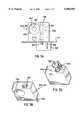
- FIG. 3A, 3B and 3Care side, top perspective, and bottom perspective views, respectively, of one embodiment of a drive mechanism for the metrology frame;
- FIG. 4is a side view of the lead screw assembly of FIG. 1;
- FIG. 5is a perspective view of a metrology frame in accordance with a second embodiment of the present invention illustrating another drive mechanism
- FIG. 6is a top schematic view of the metrology frame of FIG. 5 which incorporates a guide rod for the aligning brackets.
- FIG. 1is a perspective view of one embodiment of a metrology frame 100 of the present invention that is used to align, integrate and automate certain portions of the optical fiber interconnection process, as well as facilitate handling of the optical fibers between steps of the process.
- a metrology frame 100the general steps of an optical fiber fusion process are described below. While the description below refers to an exemplary fusion process, one of ordinary skill in the art would realize that the metrology frame described herein can be employed during any conventional fusion or connectorization process.
- the optical fiber fusion processrequires a number of steps as herein described.
- most fibersare individually coated with one or two polymeric coatings, typically 65 to 185 ⁇ m in thickness, to preserve the intrinsic strength of the fiber and permit fiber handling.
- this protective coatingmust be removed, either mechanically, thermally, or by using a chemical solvent.
- the stripped fiber endsare cleaned in an alcohol or other cleaning solution using an ultrasonic cleaner. Thereafter the fiber is cleaved by scribing the fiber with a diamond and carbide scribe to induce a break. The fiber ends then undergo the actual fusion splicing step.
- a ultraviolet (UV) recoat stepis performed to cover the exposed stripped and spliced portions of the fiber with a polymer for protection against the outside environment.
- a pull-testis performed on the fibers to test the strength of the splice, usually with at least a 150 Kpsi pull being applied to the fibers.
- the metrology frame 100is used to hold, transport and align the optical fibers to be connected, and the fiber cassettes from which the optical fibers extend, during an optical fiber interconnection process.
- the metrology frame 100includes an elongated lateral rail 110 serving as the attachment point for the majority of the components of the frame.
- a vertical support member 120extends from an upper surface of the rail 110.
- the vertical support member 120contains an attachment or end effector device 122 to allow a robot or gantry system to pick-up and transport the entire metrology frame 100 between the various steps of the interconnect process. Since the frame 100 will be transported via the end effector 122, it is preferable to provide the vertical support 120 at a central location on the rail 110 to ensure the frame 100 is balanced during the transfer procedures.
- the vertical support member 120includes a plurality of vertically spaced attachment devices 124.
- a fiber cassette holder 130includes a projection 132 that contacts and rests on the attachment device 124 to detachably attach the fiber cassette holder 130 to the vertical support member 120 in a substantially horizontal orientation with reference to the vertical support member 120.
- the attachment device 124comprises a projecting support bracket.
- the attachment device chosenshould provide a secure fit when the fiber cassette holder 130 and the vertical support member 120 are attached, but still provide the capability for easy insertion and removal.
- the vertical support member 120need only contain one attachment device 124, it is preferable to provide a plurality of attachment devices 124 so as to accommodate a plurality of fiber cassette holders 130.
- the advantage of providing several fiber cassettes 140 on the metrology frame 100is that splicing or connecting operations can be serially performed on the optical fibers 145 wound on each of the fiber cassettes 140. Also, in many cases, an optical fiber 145 from one fiber cassette 140 is spliced to an optical fiber 145 of another fiber cassette 140. By having two or more of the fiber cassettes 140 readily available and in the same place, the splicing or connecting operations can be executed more quickly.
- a pair of aligning brackets 200 and 210are provided on either side of the vertical support 120.
- the aligning brackets 200, 210have an L-shaped lower surface 220 that contacts the upper surface of the rail 110.
- the brackets 200, 210are laterally movable or slidable along the rail 110 as described later in the specification.
- the vertical portion 213 of each of the brackets 200, 210contains a threaded lateral via opening 230.
- the opening 230is threaded to accommodate a lead screw 400 as described later.
- the flange portion 215 of each of the brackets 200, 210includes an aligning device 240 (see FIG. 1) to align and secure the optical fibers during the interconnecting processes. As shown in FIG.
- the optical fibers 145 from the fiber cassette 140are passed through the aligning devices 240.
- the aligning devices 240 in FIG. 1are represented as cube-shaped devices for ease of illustration. However, it is understood that any number of conventional or custom aligning mechanisms may be incorporated into the metrology frame 100 of the present invention. Regardless of the aligning device or mechanism employed, it is important that the optical fiber ends 145a be movable toward and away from each other. As shown in FIG. 1 for example, after the optical fiber ends 145a are aligned by the aligning devices 240, they are in position to undergo the various steps of the fusion or connectorization process between the respective brackets 200, 210 in the area denoted by reference letter M.
- a frame leg 300is attached to one end of the rail 110 and another frame leg 310 is attached to the other end of the rail 110.
- the frame legs 300, 310not only provide stability to the rail 110 and the overall frame 100, in this embodiment they house a drive mechanism to move the aligning brackets 200, 210 along the rail 110.
- the ability to move the brackets 200, 210 along the rail 110provides a significant amount of flexibility in performing the fusion or connectorization process steps without ever having to remove the optical fibers 145 from the aligning devices 240 on the frame 100. This saves time and reduces the need to manually shift or transfer the optical fibers 145, which results in a quicker fusion or connectorization process with a greatly reduced susceptibility to human error or human variation.
- a drive mechanismto move both of the brackets 200, 210 and the discussion below is directed to such an embodiment. While the following discussion describes the operation of one of the drive mechanisms, it is understood that the description is equally applicable to the other drive mechanism.
- the drive mechanism for moving the aligning bracketsincludes a motor 320, shown in one embodiment disposed below a planar surface 515 on which the frame legs 300, 310 rest (FIG. 3A).
- a worm assembly 340is housed within each of the frame legs.
- the worm assembly 340has a shaft 325 extending from the bottom surface of the frame legs to contact the motor 320.
- the motor 320operates to rotate the shaft 325 about its vertical axis.
- the upper part of the shaftis capped by a bearing 341.
- the worm assemblyfurther includes a worm gear 342, the operation of which will be described further below.
- a lead screw assembly 400has one end rotatably connected to the motor 320 through the worm assembly 340, and another end rotatably connected to the threaded opening 230 in the aligning bracket 200, 210. More specifically, one end 411 of the screw shaft 410 contacts the threads of the threaded opening 230 in the aligning brackets 200 or 210. The opposite end 412 of the screw shaft 410 is attached to a worm gear 420.
- the worm gear 420 of the screw assembly 400fits into the recess 330 of the frame leg 300 or 310 as shown in FIG. 3A and FIG. 3B.
- the worm gear 420 of the screw assembly 400intermeshes with the worm gear 342 of the worm assembly 340 disposed inside the frame legs 300 or 310.
- Reference numeral 430denotes a radial thrust bearing.
- the motor 320rotates the shaft 325 of the worm assembly 340, which axially rotates the worm gear 342 as well.
- the axial rotation of the worm gear 342is converted to lateral rotation of the screw assembly 400, that is, coincident with the direction of the rail 110, by the intermeshing of worm gear 342 and worm gear 420.
- the rotation of the screw shaft 410causes the brackets 200 or 210 to move along the rail 110 as the end 411 of the screw shaft 410 intermeshes with the threaded opening 230.
- the motor 320is operative to rotate the shaft 325 in either a clockwise or counter-clockwise manner, so that the brackets 200 or 210 can move either toward or away from each other in the vicinity of the working area M.
- the frame 100further includes a rail guide pin 190 centrally located along and protruding from a bottom surface of the rail 1 10 for guiding and/or stabilizing the frame.
- frame leg guide pins 350protrude from a bottom surface of each of the frame legs 300, 310 for guiding and/or stabilizing the frame legs and anchoring the motor 320.
- the frame leg guiding pins 350may be provided outside the motor 320 to anchor the frame legs to a planar surface.
- FIG. 5illustrates another preferred embodiment of the metrology frame 500 of the present invention in which the worm gear and motor mechanism of FIG. 1 is replaced by a commercially available piezoelectric motor, specifically a piezo ceramic linear motor.
- a commercially available piezoelectric motorspecifically a piezo ceramic linear motor.
- the same reference numerals in FIG. 5illustrate the same or similar parts as described in FIG. 1.
- the piezo motor 510actuates a plurality of ceramic fingers 515 extending from the piezo motor 510, which ceramic fingers 515 are pressed against a ceramic drive strip 520.
- the ceramic drive strip 520is attached by a self-adhesive backing and epoxy to each of the slidable aligning brackets 530, 540.
- application of a voltage to the piezo motor 510causes the ceramic fingers 515 to oscillate or reciprocate in either a clockwise or counter-clockwise manner, depending on the polarity of the signal pulse. Since the piezo motor 510 is fixed relative to the metrology frame 500, the oscillating motion of the ceramic fingers 515 pressed against the ceramic drive strip 520 causes movement of the ceramic drive strip 520.
- the movement of the ceramic drive strip 520results in movement of the aligning brackets 530, 540 to which the ceramic drive strip 520 is attached. Movement of the aligning brackets 530, 540 toward or away from each other is achieved by changing the polarity of the signal pulse, which changes the oscillation direction of the ceramic fingers 515 pressed against the ceramic drive strip 520. Pulse amplitude dictates the velocity of the movement. The ultimate travel distance is governed by the length of the ceramic drive strip 520. This distance would be selected based on the predicted range of travel required by the aligning brackets 530, 540 to execute a fusion or connectorization process.
- Reference numeral 550represents a linear encoder 550 mounted to the piezo motor 510 for providing a feedback loop for the motor position for maximizing the high resolution achieved through the operation of the piezo motor.
- the piezo motor driven movement in this embodimentis more precise (nanometer resolution) than the worm gear assembly motor drive mechanism in the embodiment of FIG. 1.
- Another advantage of the piezo motoris the absence of an intrinsic magnetic field, making the motor immune to external magnetic fields.
- FIG. 6illustrates a top schematic view of the metrology frame 500 incorporating a center bracket 560 connected to the vertical support member 120 and extending between the aligning brackets 530, 540.
- a guide rod 570is connected between the frame legs 300, 310 and passes through openings 531, 561, and 541 in respective of the aligning bracket 530, center bracket 560, and aligning bracket 540.
- the guide rod 570provides lateral guidance for the slidable aligning brackets 530, 540.
- a plurality of centering springsmay be disposed along portions of the guide rod 570 for establishing a reference location for the aligning brackets by maintaining the relative position between the aligning brackets 530, 540 themselves, as well as between the respective aligning bracket 530 or 540 and the adjacent frame leg 300 or 310.
- four centering springs 581, 582, 583 and 584are provided, although less or more can be provided.
- centering spring 581is disposed along a portion of the guide rod 570 between frame leg 300 and aligning bracket 530; centering spring 582 is disposed along a portion of the guide rod 570 between aligning bracket 530 and center bracket 560; centering spring 583 is disposed along a portion of the guide rod 570 between center bracket 560 and aligning bracket 540; and centering spring 584 is disposed along a portion of the guide rod 570 between aligning bracket 540 and frame leg 310.
- Centering springs 582 and 583may be replaced by a single spring, in which case the center bracket can be eliminated.
- the location and/or elastic strength of the centering springscan be optimized for certain critical processes, such as to provide a desired degree of tension during the actual splicing step in an overall fusion process.
- the metrology frameprovides a versatile and stable mechanism to hold, transport and align the optical fibers during any interconnecting process, whether a fusion process or a connectorization process.
- the metrology framewould be manually or automatically positioned adjacent to or over a working area in order to execute the task. After the task is completed, the entire metrology frame would be moved to another location so that the next step in the fusion process or connectorization process can be executed. This sequential transfer of the frame among the work areas can be carried out with a minimum amount of human intervention and without having to remove and replace the optical fibers from one holding device to another.
Landscapes
- Physics & Mathematics (AREA)
- Engineering & Computer Science (AREA)
- Plasma & Fusion (AREA)
- General Physics & Mathematics (AREA)
- Optics & Photonics (AREA)
- Mechanical Coupling Of Light Guides (AREA)
Abstract
Description
Claims (16)
Priority Applications (1)
| Application Number | Priority Date | Filing Date | Title |
|---|---|---|---|
| US09/017,327US6088503A (en) | 1998-02-02 | 1998-02-02 | Optical fiber precision handling tool |
Applications Claiming Priority (1)
| Application Number | Priority Date | Filing Date | Title |
|---|---|---|---|
| US09/017,327US6088503A (en) | 1998-02-02 | 1998-02-02 | Optical fiber precision handling tool |
Publications (1)
| Publication Number | Publication Date |
|---|---|
| US6088503Atrue US6088503A (en) | 2000-07-11 |
Family
ID=21781973
Family Applications (1)
| Application Number | Title | Priority Date | Filing Date |
|---|---|---|---|
| US09/017,327Expired - LifetimeUS6088503A (en) | 1998-02-02 | 1998-02-02 | Optical fiber precision handling tool |
Country Status (1)
| Country | Link |
|---|---|
| US (1) | US6088503A (en) |
Cited By (30)
| Publication number | Priority date | Publication date | Assignee | Title |
|---|---|---|---|---|
| US6434314B1 (en) | 2001-03-13 | 2002-08-13 | 3M Innovative Properties Company | Force equalizing filament clamp |
| WO2002072497A1 (en) | 2001-03-13 | 2002-09-19 | 3M Innovative Properties Company | Filament recoating apparatus and method |
| WO2002073273A1 (en)* | 2001-03-13 | 2002-09-19 | 3M Innovative Properties Company | Filament organizer |
| WO2002072496A1 (en) | 2001-03-13 | 2002-09-19 | 3M Innovative Properties Company | Filament recoating apparatus and method |
| US6478481B2 (en)* | 1999-09-09 | 2002-11-12 | The Furukawa Electric Co., Ltd. | Screening mechanism for optical fiber fusion-splicer |
| US6532327B1 (en) | 2001-03-13 | 2003-03-11 | 3M Innovative Properties Company | Refractive index grating manufacturing process |
| US6547920B2 (en) | 2001-03-13 | 2003-04-15 | 3M Innovative Properties | Chemical stripping apparatus and method |
| WO2002073259A3 (en)* | 2001-03-13 | 2003-09-04 | 3M Innovative Properties Co | Apparatus and method for filament tensioning |
| US6622376B1 (en)* | 2000-04-13 | 2003-09-23 | Capewell Components Company, Llc | Cylindrical fiber holder |
| EP1361466A2 (en)* | 2002-03-13 | 2003-11-12 | Tellabs Oy | Transport box and method for storing optical fiber components |
| US20030223712A1 (en)* | 2002-05-31 | 2003-12-04 | Chapman Thomas R. | Optical fiber splice manufacturing process |
| US20040190834A1 (en)* | 2003-03-24 | 2004-09-30 | Bush Simon P. | Low profile local injection and detection system for optical fiber waveguides |
| US20040190850A1 (en)* | 2003-03-25 | 2004-09-30 | Holam Chau | Automatic apparatus for cleaving optical fiber waveguides |
| US20040190838A1 (en)* | 2003-03-24 | 2004-09-30 | Bush Simon P. | Low profile system for joining optical fiber waveguides |
| US6810192B2 (en) | 2001-07-06 | 2004-10-26 | Ksaria Corporation | Tray for a coiled optical fiber |
| US20040258370A1 (en)* | 2003-03-25 | 2004-12-23 | Bush Simon P. | System for joining polarization-maintaining optical fiber waveguides |
| US20080085565A1 (en)* | 2002-08-20 | 2008-04-10 | Cyvera Corporation | Method of reading encoded particles |
| US20110044600A1 (en)* | 2007-09-25 | 2011-02-24 | Ksaria Corporation | Apparatus for shaping the end of an optical fiber |
| US7898735B2 (en)* | 2002-09-12 | 2011-03-01 | Illumina, Inc. | Methods and systems for writing an optical code within or on a fiber substrate |
| US7900836B2 (en) | 2002-08-20 | 2011-03-08 | Illumina, Inc. | Optical reader system for substrates having an optically readable code |
| US7901630B2 (en) | 2002-08-20 | 2011-03-08 | Illumina, Inc. | Diffraction grating-based encoded microparticle assay stick |
| US8049893B2 (en) | 2003-01-22 | 2011-11-01 | Illumina, Inc. | Methods of identifying analytes and using encoded particles |
| US8081792B2 (en) | 2003-08-20 | 2011-12-20 | Illumina, Inc. | Fourier scattering methods for encoding microbeads and methods and apparatus for reading the same |
| US8254738B2 (en) | 2010-08-27 | 2012-08-28 | Ksaria Corporation | Methods and systems for efficient installation of cables in watercraft |
| US8470605B2 (en) | 2002-09-12 | 2013-06-25 | Illumina, Inc. | Optical reader for reading encoded microparticles |
| US8498052B2 (en) | 2002-08-20 | 2013-07-30 | Illumina, Inc. | Composition including an item and an encoded optical substrate and a method for identifying an item |
| US8614852B2 (en) | 2002-08-20 | 2013-12-24 | Illumina, Inc. | Elongated microparticles having an optically detectable code configured to at least one of reflect or filter light |
| US9239428B2 (en) | 2011-09-28 | 2016-01-19 | Ksaria Corporation | Epoxy dispensing system and dispensing tip used therewith |
| JP2016167012A (en)* | 2015-03-10 | 2016-09-15 | Seiオプティフロンティア株式会社 | Method and device for fusion-splicing optical fibers |
| JP2018163311A (en)* | 2017-03-27 | 2018-10-18 | 古河電気工業株式会社 | Fusion machine |
Citations (4)
| Publication number | Priority date | Publication date | Assignee | Title |
|---|---|---|---|---|
| US4736632A (en)* | 1985-09-19 | 1988-04-12 | Bicc Public Limited Company | Optical fibre splicing |
| US4995728A (en)* | 1988-12-16 | 1991-02-26 | Siemens Aktiengesellschaft | Configuration with several splicing modules |
| US5430823A (en)* | 1990-10-04 | 1995-07-04 | Alcatel Cable Interface | Optical fiber connection cassette |
| US5453653A (en)* | 1993-07-09 | 1995-09-26 | Nanomotion Ltd. | Ceramic motor |
- 1998
- 1998-02-02USUS09/017,327patent/US6088503A/ennot_activeExpired - Lifetime
Patent Citations (4)
| Publication number | Priority date | Publication date | Assignee | Title |
|---|---|---|---|---|
| US4736632A (en)* | 1985-09-19 | 1988-04-12 | Bicc Public Limited Company | Optical fibre splicing |
| US4995728A (en)* | 1988-12-16 | 1991-02-26 | Siemens Aktiengesellschaft | Configuration with several splicing modules |
| US5430823A (en)* | 1990-10-04 | 1995-07-04 | Alcatel Cable Interface | Optical fiber connection cassette |
| US5453653A (en)* | 1993-07-09 | 1995-09-26 | Nanomotion Ltd. | Ceramic motor |
Cited By (51)
| Publication number | Priority date | Publication date | Assignee | Title |
|---|---|---|---|---|
| US6478481B2 (en)* | 1999-09-09 | 2002-11-12 | The Furukawa Electric Co., Ltd. | Screening mechanism for optical fiber fusion-splicer |
| US6622376B1 (en)* | 2000-04-13 | 2003-09-23 | Capewell Components Company, Llc | Cylindrical fiber holder |
| US6665483B2 (en) | 2001-03-13 | 2003-12-16 | 3M Innovative Properties Company | Apparatus and method for filament tensioning |
| WO2002072497A1 (en) | 2001-03-13 | 2002-09-19 | 3M Innovative Properties Company | Filament recoating apparatus and method |
| WO2002073273A1 (en)* | 2001-03-13 | 2002-09-19 | 3M Innovative Properties Company | Filament organizer |
| US20020172777A1 (en)* | 2001-03-13 | 2002-11-21 | 3M Innovative Properties Company | Filament recoating apparatus and method |
| US6503327B2 (en) | 2001-03-13 | 2003-01-07 | 3M Innovative Properties Company | Filament recoating apparatus and method |
| US6532327B1 (en) | 2001-03-13 | 2003-03-11 | 3M Innovative Properties Company | Refractive index grating manufacturing process |
| US6547920B2 (en) | 2001-03-13 | 2003-04-15 | 3M Innovative Properties | Chemical stripping apparatus and method |
| US6600866B2 (en) | 2001-03-13 | 2003-07-29 | 3M Innovative Properties Company | Filament organizer |
| WO2002073259A3 (en)* | 2001-03-13 | 2003-09-04 | 3M Innovative Properties Co | Apparatus and method for filament tensioning |
| US6434314B1 (en) | 2001-03-13 | 2002-08-13 | 3M Innovative Properties Company | Force equalizing filament clamp |
| US6666984B2 (en) | 2001-03-13 | 2003-12-23 | Anthony William Gatica | Chemical stripping apparatus and method |
| US6783597B2 (en) | 2001-03-13 | 2004-08-31 | 3M Innovative Properties Company | Filament recoating apparatus and method |
| WO2002072496A1 (en) | 2001-03-13 | 2002-09-19 | 3M Innovative Properties Company | Filament recoating apparatus and method |
| US6810192B2 (en) | 2001-07-06 | 2004-10-26 | Ksaria Corporation | Tray for a coiled optical fiber |
| EP1361466A2 (en)* | 2002-03-13 | 2003-11-12 | Tellabs Oy | Transport box and method for storing optical fiber components |
| US20030223712A1 (en)* | 2002-05-31 | 2003-12-04 | Chapman Thomas R. | Optical fiber splice manufacturing process |
| US7029187B2 (en)* | 2002-05-31 | 2006-04-18 | Corning Incorporated | Optical fiber splice manufacturing process |
| US7900836B2 (en) | 2002-08-20 | 2011-03-08 | Illumina, Inc. | Optical reader system for substrates having an optically readable code |
| US8333325B2 (en) | 2002-08-20 | 2012-12-18 | Illumina, Inc. | Optical reader system for substrates having an optically readable code |
| US8498052B2 (en) | 2002-08-20 | 2013-07-30 | Illumina, Inc. | Composition including an item and an encoded optical substrate and a method for identifying an item |
| US7923260B2 (en) | 2002-08-20 | 2011-04-12 | Illumina, Inc. | Method of reading encoded particles |
| US8614852B2 (en) | 2002-08-20 | 2013-12-24 | Illumina, Inc. | Elongated microparticles having an optically detectable code configured to at least one of reflect or filter light |
| US7901630B2 (en) | 2002-08-20 | 2011-03-08 | Illumina, Inc. | Diffraction grating-based encoded microparticle assay stick |
| US20080085565A1 (en)* | 2002-08-20 | 2008-04-10 | Cyvera Corporation | Method of reading encoded particles |
| US20110033948A9 (en)* | 2002-08-20 | 2011-02-10 | Cyvera Corporation | Method of reading encoded particles |
| US8470605B2 (en) | 2002-09-12 | 2013-06-25 | Illumina, Inc. | Optical reader for reading encoded microparticles |
| US7898735B2 (en)* | 2002-09-12 | 2011-03-01 | Illumina, Inc. | Methods and systems for writing an optical code within or on a fiber substrate |
| US8049893B2 (en) | 2003-01-22 | 2011-11-01 | Illumina, Inc. | Methods of identifying analytes and using encoded particles |
| US9268983B2 (en) | 2003-01-22 | 2016-02-23 | Illumina, Inc. | Optical system and method for reading encoded microbeads |
| US20040190834A1 (en)* | 2003-03-24 | 2004-09-30 | Bush Simon P. | Low profile local injection and detection system for optical fiber waveguides |
| US20060266082A1 (en)* | 2003-03-24 | 2006-11-30 | Aurora Optics, Inc. | Low profile system for joining optical fiber waveguides |
| US20040190838A1 (en)* | 2003-03-24 | 2004-09-30 | Bush Simon P. | Low profile system for joining optical fiber waveguides |
| US7070342B2 (en) | 2003-03-24 | 2006-07-04 | Aurora Instruments, Inc. | Low profile system for joining optical fiber waveguides |
| US7004640B2 (en) | 2003-03-24 | 2006-02-28 | Aurora Instruments, Inc. | Low profile local injection and detection system for optical fiber waveguides |
| US7255498B2 (en) | 2003-03-24 | 2007-08-14 | Bush Simon P | Low profile system for joining optical fiber waveguides |
| US6984077B2 (en) | 2003-03-25 | 2006-01-10 | Aurora Instruments, Inc. | System for joining polarization-maintaining optical fiber waveguides |
| US20040258370A1 (en)* | 2003-03-25 | 2004-12-23 | Bush Simon P. | System for joining polarization-maintaining optical fiber waveguides |
| US20040190850A1 (en)* | 2003-03-25 | 2004-09-30 | Holam Chau | Automatic apparatus for cleaving optical fiber waveguides |
| US7090414B2 (en) | 2003-03-25 | 2006-08-15 | Aurora Instruments, Inc. | Automatic apparatus for cleaving optical fiber waveguides |
| US8081792B2 (en) | 2003-08-20 | 2011-12-20 | Illumina, Inc. | Fourier scattering methods for encoding microbeads and methods and apparatus for reading the same |
| US8565475B2 (en) | 2003-08-20 | 2013-10-22 | Illumina, Inc. | Optical system and method for reading encoded microbeads |
| US8406598B2 (en) | 2007-09-25 | 2013-03-26 | Ksaria Corporation | Apparatus for shaping the end of an optical fiber |
| US20110044600A1 (en)* | 2007-09-25 | 2011-02-24 | Ksaria Corporation | Apparatus for shaping the end of an optical fiber |
| US8478096B2 (en) | 2010-08-27 | 2013-07-02 | Ksaria Corporation | Methods and systems for efficient installation of cables in watercraft |
| US8577194B2 (en) | 2010-08-27 | 2013-11-05 | Ksaria Corporation | Methods and systems for efficient installation of cables in watercraft |
| US8254738B2 (en) | 2010-08-27 | 2012-08-28 | Ksaria Corporation | Methods and systems for efficient installation of cables in watercraft |
| US9239428B2 (en) | 2011-09-28 | 2016-01-19 | Ksaria Corporation | Epoxy dispensing system and dispensing tip used therewith |
| JP2016167012A (en)* | 2015-03-10 | 2016-09-15 | Seiオプティフロンティア株式会社 | Method and device for fusion-splicing optical fibers |
| JP2018163311A (en)* | 2017-03-27 | 2018-10-18 | 古河電気工業株式会社 | Fusion machine |
Similar Documents
| Publication | Publication Date | Title |
|---|---|---|
| US6088503A (en) | Optical fiber precision handling tool | |
| US6122936A (en) | Apparatus for integrating steps of a process for interconnecting optical fibers | |
| US6003341A (en) | Device for making fiber couplers automatically | |
| CN113740973B (en) | Flexible optical fiber circuit and manufacturing method thereof | |
| KR970004472B1 (en) | Optical connector connecting apparatus and optical connector connecting method | |
| US5857047A (en) | Automated fiber pigtailing machine | |
| EP0778957A2 (en) | System and method for aligning and attaching optical fibers to optical waveguides, and products obtained thereby | |
| WO2002073273A1 (en) | Filament organizer | |
| JP3009591B2 (en) | Polishing method of optical fiber end | |
| US20020168147A1 (en) | Optical circuit pick and place machine | |
| JP2001075026A (en) | Reflection mirror type optical fiber switch | |
| US7068891B1 (en) | System and method for positioning optical fibers | |
| US6690864B1 (en) | System and method for installation and alignment of optical fiber | |
| EP3841413B1 (en) | Optical fiber mass splice methods and assemblies | |
| Parry et al. | An automated multiobject fibre optic coupler for the Anglo-Australian telescope | |
| EP1315990A1 (en) | Recoating of optical fiber | |
| US6665483B2 (en) | Apparatus and method for filament tensioning | |
| KR900008299B1 (en) | Measuring method and apparatus of light fiber | |
| JPH08201650A (en) | Device for adjusting parallelism of end surface of optical substrate | |
| US7712981B2 (en) | Compact, active alignment fusion splicer with automatic view-angle compensation | |
| US6503327B2 (en) | Filament recoating apparatus and method | |
| US6942397B2 (en) | Packaging for a fiber-coupled optical device | |
| US5353361A (en) | Method for assembling a light wave guide switch | |
| WO2002067034A2 (en) | Optical circuit pick and place machine | |
| NL2025616B1 (en) | Apparatus and method for alignment of an optical component with a further optical component |
Legal Events
| Date | Code | Title | Description |
|---|---|---|---|
| AS | Assignment | Owner name:CIENA CORPORATION, MARYLAND Free format text:ASSIGNMENT OF ASSIGNORS INTEREST;ASSIGNORS:CHANDLER, WILLIAM KEITH;BOYER, THOMAS R.;SHAH, NADIR;REEL/FRAME:009320/0138 Effective date:19980716 | |
| STCF | Information on status: patent grant | Free format text:PATENTED CASE | |
| AS | Assignment | Owner name:CIENA PROPERTIES, INC., DELAWARE Free format text:ASSIGNMENT OF ASSIGNORS INTEREST;ASSIGNOR:CIENA CORPORATION;REEL/FRAME:013578/0749 Effective date:20010216 | |
| FPAY | Fee payment | Year of fee payment:4 | |
| AS | Assignment | Owner name:CIENA CORPORATION, MARYLAND Free format text:MERGER;ASSIGNOR:CIENA PROPERTIES;REEL/FRAME:016069/0435 Effective date:20041029 | |
| FPAY | Fee payment | Year of fee payment:8 | |
| FPAY | Fee payment | Year of fee payment:12 | |
| AS | Assignment | Owner name:DEUTSCHE BANK AG NEW YORK BRANCH, NEW YORK Free format text:SECURITY INTEREST;ASSIGNOR:CIENA CORPORATION;REEL/FRAME:033329/0417 Effective date:20140715 | |
| AS | Assignment | Owner name:BANK OF AMERICA, N.A., AS ADMINISTRATIVE AGENT, NO Free format text:PATENT SECURITY AGREEMENT;ASSIGNOR:CIENA CORPORATION;REEL/FRAME:033347/0260 Effective date:20140715 | |
| AS | Assignment | Owner name:CIENA CORPORATION, MARYLAND Free format text:RELEASE BY SECURED PARTY;ASSIGNOR:DEUTSCHE BANK AG NEW YORK BRANCH;REEL/FRAME:050938/0389 Effective date:20191028 | |
| AS | Assignment | Owner name:BANK OF AMERICA, N.A., AS COLLATERAL AGENT, ILLINO Free format text:PATENT SECURITY AGREEMENT;ASSIGNOR:CIENA CORPORATION;REEL/FRAME:050969/0001 Effective date:20191028 | |
| AS | Assignment | Owner name:CIENA CORPORATION, MARYLAND Free format text:RELEASE BY SECURED PARTY;ASSIGNOR:BANK OF AMERICA, N.A.;REEL/FRAME:065630/0232 Effective date:20231024 |