US6088351A - Method and apparatus for accommodating signal blockage in satellite mobile radio systems - Google Patents
Method and apparatus for accommodating signal blockage in satellite mobile radio systemsDownload PDFInfo
- Publication number
- US6088351A US6088351AUS08/872,752US87275297AUS6088351AUS 6088351 AUS6088351 AUS 6088351AUS 87275297 AUS87275297 AUS 87275297AUS 6088351 AUS6088351 AUS 6088351A
- Authority
- US
- United States
- Prior art keywords
- source signal
- signal
- versions
- multiple versions
- time
- Prior art date
- Legal status (The legal status is an assumption and is not a legal conclusion. Google has not performed a legal analysis and makes no representation as to the accuracy of the status listed.)
- Expired - Lifetime
Links
- 238000000034methodMethods0.000titleclaimsdescription80
- 230000005540biological transmissionEffects0.000claimsabstractdescription39
- 230000003111delayed effectEffects0.000claimsabstractdescription32
- 230000006835compressionEffects0.000claimsdescription26
- 238000007906compressionMethods0.000claimsdescription26
- 238000004891communicationMethods0.000claimsdescription20
- 238000012545processingMethods0.000claimsdescription18
- 230000010287polarizationEffects0.000claimsdescription16
- 239000002131composite materialSubstances0.000claimsdescription9
- 230000001934delayEffects0.000claimsdescription6
- 238000012937correctionMethods0.000claimsdescription4
- 230000000694effectsEffects0.000claimsdescription4
- 230000003044adaptive effectEffects0.000claimsdescription3
- 238000005562fadingMethods0.000claims2
- 230000000295complement effectEffects0.000claims1
- 239000000872bufferSubstances0.000description106
- 238000010586diagramMethods0.000description15
- 238000003860storageMethods0.000description8
- 238000001514detection methodMethods0.000description7
- 238000005070samplingMethods0.000description6
- 230000006837decompressionEffects0.000description4
- 238000003780insertionMethods0.000description4
- 230000037431insertionEffects0.000description4
- 230000000116mitigating effectEffects0.000description4
- 230000007480spreadingEffects0.000description4
- 238000003892spreadingMethods0.000description4
- 230000008901benefitEffects0.000description3
- 238000010276constructionMethods0.000description3
- 238000013461designMethods0.000description3
- 230000001360synchronised effectEffects0.000description3
- 230000003321amplificationEffects0.000description2
- 238000012217deletionMethods0.000description2
- 230000037430deletionEffects0.000description2
- 230000006870functionEffects0.000description2
- 238000003199nucleic acid amplification methodMethods0.000description2
- 230000003287optical effectEffects0.000description2
- 230000008569processEffects0.000description2
- 230000003252repetitive effectEffects0.000description2
- 230000005236sound signalEffects0.000description2
- 230000002123temporal effectEffects0.000description2
- 230000001052transient effectEffects0.000description2
- 230000004308accommodationEffects0.000description1
- 238000013459approachMethods0.000description1
- 230000000903blocking effectEffects0.000description1
- 238000006243chemical reactionMethods0.000description1
- 238000001914filtrationMethods0.000description1
- 230000036039immunityEffects0.000description1
- 239000007924injectionSubstances0.000description1
- 238000002347injectionMethods0.000description1
- 238000004519manufacturing processMethods0.000description1
- 238000012856packingMethods0.000description1
- 230000009467reductionEffects0.000description1
- 238000000926separation methodMethods0.000description1
- 230000036962time dependentEffects0.000description1
Images


Classifications
- H—ELECTRICITY
- H04—ELECTRIC COMMUNICATION TECHNIQUE
- H04B—TRANSMISSION
- H04B7/00—Radio transmission systems, i.e. using radiation field
- H04B7/14—Relay systems
- H04B7/15—Active relay systems
- H04B7/185—Space-based or airborne stations; Stations for satellite systems
- H04B7/18523—Satellite systems for providing broadcast service to terrestrial stations, i.e. broadcast satellite service
- H—ELECTRICITY
- H04—ELECTRIC COMMUNICATION TECHNIQUE
- H04H—BROADCAST COMMUNICATION
- H04H20/00—Arrangements for broadcast or for distribution combined with broadcast
- H04H20/20—Arrangements for broadcast or distribution of identical information via plural systems
- H—ELECTRICITY
- H04—ELECTRIC COMMUNICATION TECHNIQUE
- H04H—BROADCAST COMMUNICATION
- H04H20/00—Arrangements for broadcast or for distribution combined with broadcast
- H04H20/53—Arrangements specially adapted for specific applications, e.g. for traffic information or for mobile receivers
- H04H20/57—Arrangements specially adapted for specific applications, e.g. for traffic information or for mobile receivers for mobile receivers
- H—ELECTRICITY
- H04—ELECTRIC COMMUNICATION TECHNIQUE
- H04H—BROADCAST COMMUNICATION
- H04H40/00—Arrangements specially adapted for receiving broadcast information
- H04H40/18—Arrangements characterised by circuits or components specially adapted for receiving
- H04H40/27—Arrangements characterised by circuits or components specially adapted for receiving specially adapted for broadcast systems covered by groups H04H20/53 - H04H20/95
- H04H40/90—Arrangements characterised by circuits or components specially adapted for receiving specially adapted for broadcast systems covered by groups H04H20/53 - H04H20/95 specially adapted for satellite broadcast receiving
Definitions
- the present inventiongenerally relates to a system for accommodating radio signal blockage, and in particular to a system for accommodating signal blockage in satellite mobile radio systems.
- Radio channelsare beamed from earth ground stations to orbiting satellites, which in turn beam the radio channels to individual users all over the earth.
- a broadcast studioIn existing satellite radio systems, a broadcast studio generates analog audio signals much the same as a conventional radio station studio does. For example, an announcer provides real-time narration, and then typically plays music selections from a library of CD music albums.
- the analog signalsare converted to a digital stream of samples, called PCM ("Pulse code modulation").
- PCMPulse code modulation
- the conversionis performed for real-time voice or live music performances by passing the analog signals to an A/D ("analog-to-digital converter").
- the digital outputconsists of 16 bit linearly quantized waveform amplitude samples for two channels (stereo right and left), at a sampling rate of approximately 44 kilosamples per second ("ksps"). This is the data stream quality of CD music in temporal sampling resolution and amplitude resolution.
- the A/D stepis not necessary since the audio data is already in a digital format on the CD.
- the digital audio datais then passed to a satellite ground station for transmission to a satellite on its radio frequency "uplink" carrier.
- the datacan be compressed to save bandwidth and other system resources.
- the satellitereceives the signal from the ground station and retransmits it to the area on the earth's surface where radio reception is desired.
- the satellitecan have a "downlink" beam pattern that covers the continental United States.
- the user's receiverdecompresses the digital data, and converts it back to analog signals (one for each stereo channel) with a DAC ("digital-to-analog converter") for subsequent amplification and listening through loudspeakers.
- DACdigital-to-analog converter
- a useris on a mobile platform, such as a moving automobile, then unique problems are encountered.
- a mobile platformsuch as a moving automobile
- Foliageattenuates a downlink signal from the satellite, and can even render it unusable if the foliage is particularly dense.
- the obstructionscan be divided into two groups: (1) Attenuating: Those objects, such as trees or other foliage, which partially reduce signal strength, and (2) Opaque: Those objects which effectively cut off the line-of-sight signal from the satellite completely, such as telephone poles, buildings, overpasses, or even other adjacent vehicles. In the first case, there are several classical means of assuring adequate signal for acceptable reception.
- a digital audio radio systemin which multiple versions of a digital data source signal are transmitted to one or more satellites to be rebroadcast to a defined reception area, where the multiple versions are delayed relative to each other.
- One of the versionsis intended to be used by a mobile receiver if the broadcast signal from the satellite is not blocked, and the other one or more versions are intended to be used if the broadcast signal from the satellites is blocked. Because each of the multiple versions represent the same source signal that is received at different times, if the signal from the satellites is blocked, the signal being received at a different time can be used.
- the versions that are to be used when the broadcast signal is blockedcan be of a lesser data quality to conserve system resources and the versions can include complimentary and mutual information to be combined for a complete signal.
- the various versions of the source signalcan be separated using any technique in which multiple time-separated versions of the same source signal can be simultaneously transmitted and independently received and separated by a receiver.
- a time multiplexing techniquea frequency domain multiplexing technique, a code division multiplexing scheme, or different electromagnetic polarizations can be employed.
- the receivermay also be designed to perform a weighted combining of the multiple received signals for greater performance. Interleaving techniques can be used to further increase system integrity, and multiple source signals can be transmitted using any applicable channelization technique.
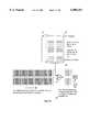
- FIG. 1illustrates a block diagram of an embodiment of a communication system according to the present invention
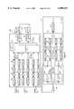
- FIG. 2is a detailed block diagram of embodiments of the pre-transmitter and post-receiver systems of FIG. 1;
- FIG. 3illustrates the architecture of the pretransmitter of FIG. 2
- FIG. 4illustrates the architecture of the post- receiver system of FIG. 2
- FIG. 5is an overall block diagram.
- FIGS. 6-12illustrate the operational steps of the system of FIG. 1 for a sequence of transmission events
- FIG. 13illustrates another embodiment of a communication system according to the present invention
- FIG. 14illustrates another embodiment of a communication system according to the present invention.
- FIG. 15illustrates yet another embodiment of a communication system according to the present invention.
- FIG. 16is a block diagram of a transmitter system illustrating an example of broadcasting multiple time separated transmissions using frequency domain multiplexing, according to an embodiment of the present invention
- FIG. 17is a block diagram of a transmitter system illustrating an example of broadcasting multiple time separated transmissions using a code division multiplexing scheme, according to an embodiment of the present invention
- FIG. 18is a block diagram of a transmitter system illustrating an example of broadcasting multiple time separated transmissions using different electromagnetic polarizations, according to an embodiment of the present invention
- FIG. 19is a block diagram of a receiver that combines multiple received versions of a source signal to increase signal-to-noise, according to an embodiment of the present invention.
- FIG. 20is a block diagram of a transmitter and receiver system broadcasting multiple time separated transmissions and incorporating interleaving, according to an embodiment of the present invention
- FIG. 21is a block diagram of a transmitter and receiver system illustrating an example of a multichannel system, according to an embodiment of the present invention.
- FIG. 22illustrates another embodiment of a communication system according to the present invention.
- FIG. 23illustrates an example dedicated logic implementation of the present invention.
- the system 10comprises a pre-transmitter system 12 including: (i) a first buffer 14 for storing a sequence of digital audio samples from an audio source 16, the first buffer 14 having a beginning 18, an end 20 and a length 22; (ii) storing means 24 for storing the audio samples in the first buffer 14 in shift register configuration format; and (iii) frame construction means 26 for constructing a data frame including a first audio sample from the end 20 of the first buffer 14 and a second audio sample from the beginning 18 of the first buffer 14.
- the data framecan be transmitted and received by a receiver.
- the communication system 10further comprises a post-receiver system 28 including: (i) a second buffer 30 having a beginning 32, an end 34 and a length 36 identical to the length 22 of the first buffer 14; (ii) storing means 38 for storing the second audio sample in the received data frame in the second buffer 30 in shift register configuration format; (iii) means 40 for determining if the data frame was properly received; and (iv) selection means 42 for selecting an audio sample for audio output, wherein the first audio sample in the data frame is selected if the data frame was properly received, otherwise, an audio sample from the end 34 of the second buffer 30 is selected.
- a post-receiver system 28including: (i) a second buffer 30 having a beginning 32, an end 34 and a length 36 identical to the length 22 of the first buffer 14; (ii) storing means 38 for storing the second audio sample in the received data frame in the second buffer 30 in shift register configuration format; (iii) means 40 for determining if the data frame was properly received; and
- null samplee.g., all bits set to 9
- the last or previous samplecan be injected into the data stream when only a few data samples are corrupt.
- Other alternativesinclude an interpolation scheme, or a gentle ramp up/down to null (0) when a stream of samples is missing to avoid a transient "pop" sound in audio output.
- the pre-transmitter system 12can be implemented utilizing a general purpose computer system programmed with instructions for performing the steps of the method of the present invention described below.
- a general purpose computer system 44includes a central processing unit (CPU) 46, memory 48, communication ports 50 and optionally, magnetic or optical storage 52 interconnected through a bus 54.
- the first buffer 14can be implemented as a ring buffer using address pointers in memory.
- the storing means 24 for storing audio samples into the first buffer 14can be a set of program instructions providing buffer operations including insertion, deletion and shifting. Audio samples arrive at the communication port 50 of the computer system 44 and are inserted into the first buffer 14 by the storage means 24 via the bus 54.
- the frame construction means 26 for constructing a data framecan be a set of program instructions for copying data samples from the end 20 and the beginning 18 of the first buffer 14.
- the data framecan be stored in a segment of the memory 48 for output through the communication port 50 via the bus 54.
- An example embodiment of a set of pseudo program instructions for implementing the means for storage and the means for constructing a frame of datais discussed in Example I below.
- the pre-transmitter system 12can also be implemented utilizing a dedicated logic system.
- the first buffer 14can be a memory shift register clocked at a desired rate for receiving audio samples and providing audio samples for transmission at that clock rate.
- the first buffer 14can also be implemented with pointers and conventional memory if preferred.
- Example II belowdescribes an example embodiment of a dedicated logic system.
- the post-receiver system 28can be implemented utilizing a general purpose computer system 44, described above, programmed with instructions for performing the steps of the method of the present invention described below.
- the second buffer 30can be implemented as a ring buffer using address pointers in memory.
- the storing means 38 for storing audio samples into the second buffer 30can be a set of program instructions providing buffer operations including insertion, deletion and shifting. Data frames arrive at the communication port 50 of the computer system 44, and the second audio sample in each data frame is inserted into the second buffer 30 by the storage means 40 via the bus 54.
- the means 40 for determining whether a data frame has been properly receivedcan be implemented by assigning a "Frame OK bit" to each Frame. By examining either the analog signal strength received or error-detection information embedded in the digital data (e.g., parity, checksum, CRC, etc.) or some combination of these, the post-receiver can establish the fidelity of data in a Frame. If no errors are detected, the Frame is assigned a "good” flag in its "OK bit,” and if not, the bit is set to "bad.” This "OK" bit is carried along with the samples through subsequent processing.
- An example embodiment of a set of pseudo program instructions for implementing the storing means 38, the means 40 for determining and the means 42 for selectingis discussed in Example I below.
- the post-receiver system 28can also be implemented utilizing discrete logic elements or chips, a gate array, or by using an embedded microprocessor CPU and ROM microcode.
- the second buffer 30can be a memory shift register clocked at a desired rate for receiving audio samples and providing audio samples for transmission at that clock rate.
- the second buffer 30can also be implemented with pointers and conventional memory if preferred. Example II below describes an example embodiment of a dedicated logic system.
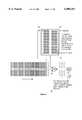
- FIGS. 6-12illustrate an example embodiment of the operational steps of the system 10 of FIGS. 1-4 for a sequence of transmission events from a transmitting ground station via a satellite to a receiving ground station.
- An audio sourcegenerates digital samples (e.g., two 16 bit channels, or 4 bytes per sample) which are received by the pre-transmitter system 12 and fed into the first buffer 14.
- digital samplese.g., two 16 bit channels, or 4 bytes per sample
- the buffer 14has an input 56 where new samples are inserted into the buffer, and an output 58 where samples are shifted out of the buffer.
- the beginning 18 of the buffer 14is at the input 56
- the end 20 of the buffer 14is at the output 58.
- the length 22 of the buffer 14determines the maximum number of digital samples that can be stored in the buffer 14 at any time.
- the buffer 14After an initial startup period, the buffer 14 is always full, and continues to migrate samples from its input 56 ("Future” sample) to its output 58 ("Present” sample). "Present” and “Future” are relative times referred to by a user radio as described below.
- the length 22 of the buffer 14 and the shift clock ratedetermine the time delay between "Present” and “Future” samples. This delay period amount can be determined for a specific embodiment such that performance is optimal for the desired operating scenarios.
- a "frame" of datais constructed for transmission via a transmission medium such as a satellite.
- the data frameconsists of both a “Future” (“F") sample, and a “Present” (“P”) sample (one delayed in time by the buffer).
- FFluture
- PPresent
- a stream of datais transmitted via an uplink consisting of pairs of samples, one "Future,” one "Present,” at every sample period.
- the effective data volume (bit rate) for transmissionhas doubled.
- the satellitethen retransmits the data stream via a downlink to a receiver, such as a user radio, in which the stream of sample pairs (Present and Future) is reconstructed from the data frames by the post-receiver system 28 according to the present invention.
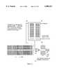
- a "Frame OK bit”is assigned to each data frame to indicate whether the data frame has been properly received. This can be implemented by examining either the analog signal strength received or error-detection information embedded in the digital data (e.g., parity, checksum, CRC, etc.) or a combination. Thus, the post-receiver system 28 can establish the fidelity of data in a data frame. If no errors are detected, the data frame is assigned a "good” flag in its "OK bit,” and if not, the bit is set to "bad.” The "OK" bit is carried along with the samples through subsequent processing.
- the second buffer 30has an input 60, corresponding to the beginning 32 of the buffer 30, and an output 62 corresponding to the end 34 of the buffer 30.
- the Future samplesare split off and injected into the input 60 of the second buffer 30.
- the length 36 of the buffer 30(delay time) matches that of the first buffer 14 in the pre-transmitter system 12.
- samplesmigrate through the second buffer 30, until at the output 60 of the buffer 30 they are identical to the Present samples from the incoming data stream.
- the "OK" bitsare preserved along with the samples as they flow through the buffer 30.
- the selection means 42includes an "OR" switch 64, utilized to select a data sample from the incoming real-time Present data samples or from the second buffer 30 for audio generation. Selection depends on the "OK" bits of the data samples. IF the real-time sample "OK bit" is "good,” then the real-time Present sample is selected. If not, the delayed Present sample is selected (assuming its OK bit is "good”). If neither sample is "good,” then a null sample (e.g., all bits set to 0) is injected into the data stream, and no audio will be produced (an unavoidable dropout occurs). Alternatively, instead of a null sample, the last or previous sample can be injected into the data stream when only a few data samples are corrupt. Other alternatives include an interpolation scheme, or a gentle ramp up/down to null (0) when a stream of samples is missing to avoid a transient "pop" sound in audio output.
- an "OR" switch 64utilized to select a data sample from the incoming real-time Present data samples or from the second buffer
- FIG. 6provides a more detailed view of the post-receiver system 28 operation.
- the buffer 30is empty and all of the OK bits in the buffer 38 are initialized to 0.
- the real-time incoming Present samplesare available as valid samples to the OR switch 64.
- a buffer length (time delay) of 60 secondsis assumed.
- FIG. 7illustrates the status of the post-receiver system 28 a short time after it has been turned on (e.g., 30 seconds).
- the buffer 30has begun to fill up with good "Future” samples, and the samples have migrated about halfway through their passage in the buffer 30.
- the OR switch 64still has only "Present” samples available as valid data.
- FIG. 8illustrates the status of the post-receiver system 28 after an initial 60 seconds after radio turn-on and continual reception of a good signal.
- the buffer 30is now full with valid samples, and is able to provide the OR switch 64 with valid delayed "Present" samples.
- FIG. 9illustrates a blockage encountered by the post-receiver system 28, causing a section of lost samples in the incoming data stream from the satellite.
- FIG. 10shows the blockage about halfway through its travel in the system 28.
- the real-time Present samplesare invalid.
- the paired Future samplesare also invalid as they are inserted into the input 60 of the buffer 30.
- the OR switch 64has good delayed-Present samples available from the output 62 of the buffer 30, and the radio continues producing audio even though the incoming signal has been completely blocked for an extended period.
- the example buffer length discussed for this example embodimentcan produce audio for blockages for as long as a full minute, as might be encountered at a stoplight or while driving through a tunnel.
- FIG. 11shows the blockage after it has passed, and good samples are again being received.
- the bad Future samples resulting from the blockagehave passed about midway through the buffer 30. Radio audio is still being produced, since the OR switch 64 has good Present samples available from real-time reception.
- FIG. 12shows the status of the post-receiver system 28 as the blockage samples in the buffer 30 exit the buffer 30 about a minute after the blockage occurred.
- FIG. 13illustrates an example implementation of another embodiment of the communication system 10 of the present invention.
- the example embodiment shown in FIG. 11incorporates the following three features by affecting the format of the "Future" samples transmitted: (1) Transmitting only monophonic audio to reduce the bit rate (and buffer storage size) by a factor of two; (2) Reducing the amplitude resolution of the Future samples from the nominal 16 bit resolution, with 8 bit amplitude resolution as a practical lower limit (a factor of two less in bit rate and storage), and 12 bit resolution as an intermediate choice (3/4 the amount of transmitted data); and (3) Reducing the sampling period of Future samples by a factor of two (22 ksps) or 4 (11 ksps). Other values for the aforementioned reductions are possible and can be selected according to desired requirements.
- the Future samplesare monophonic, 8 bits in amplitude resolution, and at an 11 ksps sampling rate (1/4 of the nominal 44 ksps rate).
- the Future samples from the buffer 14 of the pre-transmitter system 12are converted to monophonic (add the stereo signals, and divide by two), truncated to 8 bits (drop the high order, least significant byte), and reduced to one sample per every four of the nominal 44 ksps sample rate.
- the lattercould be implemented by, for example, trapping the maxima/minima within alternating four sample sections.
- the resulting single byteis combined with the transmitted nominal 16 bit, 44 ksps stereo bit stream.
- the effective increase in bit rateis about 6% (17/16 bytes per Frame). As a result, advantageously, the user radio memory requirement is drastically reduced, by a factor of 16.
- the delayed-Present data from the buffer 30is converted to emulate the standard 16 bit, stereo 44 ksps audio data stream.
- the 8 bit data (byte)is used for both the right and left stereo channel, and a null (all 0) least significant byte is added to make 16 bit samples.
- the same samplescould be replicated four times to get 44 ksps from the 11 ksps, or an "oversampling" algorithm, such as interpolation, could be applied for more sophistication.
- the present inventionalso contemplates utilizing digital audio compression to reduce the length 36 of buffer 30 for a given time delay. For example, with a compression ratio of 12:1, maintaining essentially "CD quality" sound, the buffer memory requirement is reduced to about one megabyte in size.
- the 60 second delay selected between Present and Futureis arbitrary, and can be longer or shorter as desired in an actual specific design, as determined by the maximum blockage period to be accommodated.
- FIG. 14illustrates yet another embodiment of the present invention.
- both the pre-transmitter and post-receiver buffers 14 and 30, respectivelyare tapped at a shorter delay period, labeled "Soon."
- Soona shorter delay period
- both the Future and Soon samplesare included with Present samples to construct a data frame for transmission.
- the Soon samples(along with the Future samples) would increase the transmitted bit rate by only about 12.5 percent (approximately about 6% for Future and about 6% for Soon).
- both Future and Soon samplesare stripped from the data stream frame, and the Future samples sent to the buffer input 60 as described above.
- the Soon samplesare inserted into the buffer 30 at a point in the buffer corresponding to the delay of Soon samples in the pre-transmitter 12.
- the Soon samplecan be inserted anywhere between Future and Present, such as close to Future, or in the middle of Present and Future. The insertion point depends on the specific nature of the blockage scenario a particular design is aimed at mitigating.
- the Future and Soon samplesare checked for validity and their OK bits set accordingly. If the Soon sample is invalid it is not sent to the buffer 30. If the present Sample is invalid, a delayed-Future sample during a blockage is used by the OR switch 64. In the system of FIG. 14, when short blockages occur, followed by short periods of good data, the buffer 30 is replenished rapidly below the Soon insertion point. Furthermore, if repetitive short blockages such as a row of telephone poles are encountered which are approximately synchronous with the total buffer delay, the Soon injections will prevent audio loss.
- the system of FIG. 14is advantageous for circumstances where both long and frequent short duration blockages are encountered. Objects such as telephone poles, street signs, and traffic lights produce relatively short but opaque blockages (fractions of a second). Overpasses, buildings, and passing traffic (large trucks) would typically result in relatively long blockages (several seconds).
- the system of FIG. 14remedies the situation where repetitive blockages such as telephone poles are encountered which have a separation period approximating the nominal delay of the pre-transmitter and post-receiver buffers 14 and 30, respectively. Even though the blockages are short, audio loss can occur since blockages are synchronous with the lengths 22 and 36 of the buffers 14 and 30, respectively. This is because a new blockage is encountered just as the previous blockage exits the buffer 30 of the post-receiver 28, resulting in audio loss.
- the present inventionalso contemplates use of more than one tap spread optimally throughout the buffers 14 and 30.
- FIG. 15illustrates yet another embodiment of the present invention.
- the system of FIG. 15is a hybrid design, where the Future samples are reduced in size (e.g., 8 bit monophonic at 11 ksps), but the Soon samples maintain nearly the same audio quality as the original data (e.g., CD 16 bit stereo samples at 22 ksps).
- the system of FIG. 15can be optimized for cost versus performance: short blockages would be unnoticed by the listener, while long blockages would have reduced audio quality but maintain operation.
- the post-receiver buffer 30is split into two stages: The first stage handles the long duration blockages with the 8 bit monophonic Future samples, while the second stage handles the higher quality Soon samples.
- the signal from the first satelliterepresents the Present samples
- the signal from the second satelliterepresents the Future data samples
- the signal from any additional satelliteswould have additional delay times, such as the Soon delay described.
- the advantages of this inventioncan therefore be combined with systems utilizing two (or more) satellites without link rate impact (only the shift register buffer memory and associated logic is needed).
- the nominal spatial diversity advantage of two satellitesis significantly enhanced for obviously coincident (and not just random) blockage situations, such as a bridge overpass (both satellites are definitely blocked).
- This aspect of the inventioncan also be utilized in transmission systems using low or medium altitude satellite constellations which require many satellites for global continuous coverage besides line-of-sight coverage.
- the frame construction means 26 within the pre-transmitter system 12 discussed aboveuses a multiple time-separate multiplexing technique or time domain multiple access (TDMA) for combining multiple streams of the same or substantially the same digital data to be transmitted as a single data stream, where each of the multiple streams of digital data are separated from each other by a predetermined time period.
- the multiple streams of digital dataare combined such that frames of data in the data stream include a piece of information that is currently usable, and a piece of information that will be usable in the future.
- time multiplexingis one of many techniques that can be used for transmitting a stream of digital data at one time and the same stream of digital data delayed in time, within the scope of the present invention. Any technique in which multiple time-separated versions of the same source signal can be simultaneously transmitted and independently separated by a receiver is suitable for use with a blocking mitigation technique according to the present invention.
- the “present” samples referred to aboveare the samples that the receivers use when no blockage of the transmitted signal occurs.
- the “future” and “soon” samplesare those samples that are stored in the receivers for some period of time to be later used if the transmitted signal is blocked and the "present” samples are not available. Thus, in one embodiment, it is desirable that the "present” samples be of the best quality desirable or applicable for the particular application.
- Known compression algorithmscompress the 44 ksps PCM signal to provide a compressed digital data signal having a particular bit rate per second. Typical known compression algorithms incorporate frequency domain filtering, and may use fast fourier transform (FFT) processing.
- FFTfast fourier transform
- PACpsycho-acoustic coding
- the original audio waveform itselfis not preserved and replicated, rather, key mathematical features of the waveform, such as frequency bin activity, comprise the compressed data bit stream.
- organizationssuch as Dolby, MPEG, AT&T, Musicam and others have various versions of PAC algorithms, implemented in either software or hardware.
- Each compression algorithmhas a compression factor that is the ratio of the digital data rate going in to the algorithm versus the digital data rate coming out of the algorithm.
- the best qualityis CD quality, having a compressed data rate of 128 kbps. At this rate, each frame represents about 1/30 of a second of audio.
- the various samples or legscan be filtered or separated such that two or more versions include some mutual information and some complimentary information so that when the versions are combined a complete signal is provided.
- the combination of the samplescan provide a complete signal having a predetermined level of quality of the source signal.
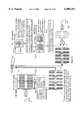
- FIG. 16shows a block diagram of a transmitter system 70 for transmitting multiple transmissions using frequency domain multiple access (FDMA) or frequency domain multiplexing.
- a digital data source signal from a data source 72is applied to several data paths, designated paths 1-n. Any number n paths suitable for the number of delayed transmissions desired for a given system can be used.
- Each data pathincludes a compression system 74 for compressing the digital data in order to conserve system resources by any suitable compression technique known in the art.
- the compressed digital data in each pathis then applied to a delay system 76 that delays the compressed digital data a predetermined time relative to each of the other paths.
- Each delay system 76would have a different delay than the other delay systems 76, and one of the paths will have a delay of zero.
- the individual delay systems 76 depicted hereshow delays of zero seconds, five seconds, ten seconds and fifteen seconds. In a practical environment, the delays would not be symmetric in this nature. Depending on the particular environment that the system 70 is being used in, delays of zero seconds, seven seconds, twenty-five seconds in three minutes may be applicable.
- the delayed and compressed digital datais then applied to a modulator 78 that modulates the digital data onto a carrier frequency suitable for transmission. Each modulator would modulate the digital data at different carrier frequencies so that they are distinguishable by the different frequencies.
- the delayed digital data signals modulated onto the different carrier wavesare then combined by a summation device 80 into a single composite broadcast signal to be transmitted by a suitable transmitter 82 to the satellite or satellites for rebroadcast to the desirable viewing area.
- the receiverwould include circuitry to separate the various frequencies from the broadcast signal, demodulate the various carrier frequencies to extract the compressed digital data, decompress the data, and delay circuitry to align the separate signal paths.
- one or more delayed transmissions of the broadcast signalare available in the receiver to be used in the event that the broadcast signal is blocked in a manner as discussed above. It is noted that in order to conserve system resources, the delayed transmissions can be of a lesser quality than the "present" signal, as discussed above.
- the same composite broadcast signalcan be transmitted as separate delayed signals.
- FIG. 17shows a block diagram of a transmitter system 86 using a code division multiplexing technique where digital source data from a data source 88 is applied to a plurality of separate paths 1-n.
- the digital data in each pathis compressed by a compression system 90 and delayed by a delay system 92.
- the compressed and delayed digital data signalsare then applied to a multiplier 94 in each path that multiplies the digital data with a unique spreading code.
- the spreading codeidentifies each of the separate paths to be later deciphered in the receiver.
- Each of the identified digital data signalsare then applied to a summation device 96 and the summed signal is applied to a modulation/transmitter 98 to be transmitted to the satellite on a carrier wave.
- a single modulatoris all that's required in the transmitter system 86 because the separate paths are not distinguished by their carrier frequencies, but by the unique spreading code.
- FIG. 18shows a block diagram of a transmitter system 100 where digital source data from a data source 102 is applied to multiple paths. Once again, the data in each path is compressed by a compression system 104 and then delayed by a delay system 106. The compressed and delayed digital data is then modulated onto a carrier wave and transmitted by a modulator/transmitter system 108.
- a first transmission pathincludes an antenna 110 that broadcasts the modulated digital data having one polarization, for example, right hand circular polarization, and a second transmission path broadcasts the digital data by an antenna 112 to have another polarization orthogonal to the first polarization, for example, a left hand circular polarization.
- Receiver circuitrywould separate the two transmissions based on these polarizations.
- the system described aboveincludes a receiver that simply selects between the multiple received versions of the source signal. Instead of this simple selection, the receiver may also be designed to perform a weighted combining of the multiple received signals. By doing this, the signal-to-noise a ratio can be increased and signal integrity will improve.
- One simple techniquewould be to align the multiple received signals in time and then add them using an adaptive algorithm that applies the correct phase matching prior to the addition. The resulting signal could then be processed by a detection algorithm.
- FIG. 19shows a block diagram of a receiver 116 that performs such a weighted combining of the multiple received signals.
- the received broadcast signalis applied to a demodulator 118 that strips away the carrier wave to separate the digital data information.
- the digital data informationis applied to a demultiplexer 120 that separates the present signal and the delayed signal.
- the non-delayed signalis applied to a time alignment delay system 122 in order to time align it with the delayed version.
- Both digital data signalsare then applied to an addition system 124 to combine the two signals using an adaptive algorithm that corrects the phase matching prior to the addition.
- the combined signal from the addition system 124is applied to a bit detection/decoding system 126 to decode the bits, and then to a decompression system 128 to decompress the data to put it into its original format.
- data interleavingmay be used in conjunction with the multiple transmission concept to provide additional immunity to time dependent blockages.
- data interleavingis a technique by which consecutive digital data bits are mixed up or separated so that groups of bit errors from various occurrences, such as interference or short duration blockage, are separated, and are more easily deciphered and detected in the receiver.
- more sophisticated systemsmay perform interleaving on some transmitted versions of a source signal and not on others to support fast acquisition and retuning.
- FIG. 20is a block diagram that shows a transmitter and receiver system 134 including a transmitter system 136 and a receiver system 138.
- a stream of digital data from a data source 140is applied to multiple paths in the transmitter system 136, where each path compresses the digital data by a compression system 142, and delays the compressed data a predetermined time by a delay system 144.
- the compressed and delayed digital data streamis then applied to an encoder 146 for encoding the digital data.
- Three of the pathsare applied to an interleaver system 148 to separate the bits in a manner that is well understood in the art.
- Each pathis then applied to a time division multiplexer 150, for example, of the type discussed above, to combine the digital data in each of the paths into a single stream of data.
- a modulator/transmitter 152modulates the digital data onto a carrier wave to be transmitted and received by an antenna 154 associated with the receiver system 138.
- the receiver system 138includes a demodulator 156 that demodulates and strips the carrier wave from the received signal to separate the digital data.
- the digital datais then applied to a demultiplexer 158 that separates the digital data signal back into the same paths as in the transmitter system 136.
- a deinterleaver 160recombines the digital data into the sequence that they were originally in, and a decoder 162 decodes the digital data for subsequent processing. Each path is then applied to an appropriate delay system 164 so that each path is aligned in time.
- a frame select system 166selects the data in the desired path to be used.
- the frame select system 166can select the data in the desired path by any technique suitable for the present invention. For example, the frame select system 166 can select the data path based on one or more of the received signal-to-noise ratio (SNR), the detected bit-error rate, the amplitude level of the received signal, and known tracking loop statistics. Additionally, an output signal can be selected on a segment-by-segment basis.
- a decompression system 168puts the digital data back into its original digital form.
- the signal in the receiver system 138 having no delayis also the signal that has no interleaving in the transmitter system 136. Consequently, it is available almost immediately for the decoding and decompression algorithms. This signal supports fast acquisition, while the additional signals that have interleaving will be more immune to burst errors in the channel.
- FIG. 21shows an example of a multichannel system 172 using a TDMA technique. This example is shown for a two-satellite system providing digital audio or radio services to mobile users.
- the system 172includes a ground station 174 and a mobile receiver 176.
- the ground station 174receives PCM data on a plurality of program channels. Each program channel is separated into a suitable number of paths where each path is time delayed as discussed above.
- Each path of each channelincludes a compression system 178 for compressing the digital data, a time delay system 180 for delaying the compressed data a suitable period of time, an encoder 182 for encoding the digital data, and an interleaver 184 for interleaving the coded digital data.
- Each path of each channelis then applied to both a first multiplexer 186 and a second multiplexer 188.
- the multiplexers 186 and 188determine the composite time ordering of the digital data from all of the delay paths of all of the source signals.
- the composite output signal from the multiplexer 186is applied to a modulator/transmitter system 190 to be transmitted to a first satellite 192, and the selected output of the multiplexer 188 is applied to a modular/transmitter 194 to be transmitted to a second satellite 196.
- the modulator/transmitter 190operates at a different frequency than the modulator/transmitter 194.
- the transmitted signals from the satellites 192 and 196are received by an antenna 198 and are applied to the mobile receiver 176.
- the signalsare simultaneously applied to a first demodulator 200 and a second demodulator 202 which strip off the separate corner frequencies.
- the separate demodulated signalsare then applied to a first demultiplexer 204 and a second demultiplexer 206 to further separate the signals into the various delay paths that were established in the ground station 174 for a selected source signal.
- Each data pathis applied to a deinterleaver 208 for deinterleaving the data, a decoder 210 for decoding the digital data, a time buffer 212 to align each of the paths of each of the channels in time, and then to a frame select 214 to select one of the particular paths of each channel.
- the selected pathis then applied to a decompression system 216 to put the digital data stream back in its original format.
- the mobile receiver 176is capable of receiving and processing only one of the channels at a time. More sophisticated receivers may duplicate the processing shown for the single channels so that additional channels may be available for fast retuning.
- the present inventionalso contemplates: (1) Terrestrial radio transmissions not utilizing satellite systems which also suffer from blockage scenarios; (2) Transmission systems such as optical links which do not utilize RF including transmission of all types of digitized electromagnetic signals; (3) Satellite-to-mobile-user data systems which include the PCS (Personal Communicator Satellite) systems for beepers, facsimile, Internet, "telegrams," electronic mail, etc.
- PCSPersonal Communicator Satellite
- Such systemsinclude systems for communication of traffic, weather or other graphically-oriented information that is continuous but may encounter dynamic blockages. Examples include systems for a dashboard display of position, traffic, and weather; and (4) Video (TV) direct broadcast systems, including any mobile and stationary receipt of TV signals when reception is intermittently obscured.
- Existing TV satellite receiver systemsfunction as long as the dish has a clear view of the satellite, but fail temporarily in the presence of heavy rainfall (cloudburst).
- the present inventioncan be utilized to alleviate such problems by, for example, utilizing a disk storage (e.g., hard disk) for storing Future (or Soon) video in a home satellite TV receiver.
- a disk storagee.g., hard disk
- the present inventionadvantageously, eliminates a severe disadvantage of existing direct satellite broadcasting to mobile radio systems. It provides conventional radio performance for satellite radios without frequent annoying losses of audio.
- the systemcan also be utilized in various industries such as commercial trucking and military applications.
- Transmitterreferred to in the description below is depicted in FIG. 16, where audio is converted from analog-to-digital and prepared for uplink to the satellite.
- Frames of dataare packed for transmission via the uplink every 1/44,100th of a second.
- a "Frame” in this examplecan have one of three sizes, depending on the content at a particular time.
- the outgoing data streamalways has a single "Present” stereo sample of 4 bytes ("P"). Every other Frame also includes a “Soon” stereo sample of 4 bytes (“S”) (8 bytes total). Every fourth Frame includes a "Present” (P) and a “Soon” (S) sample, plus a "Future” (“F”) single byte sample (9 bytes total).
- the Framescan also include a header, identifying size and type, data error detection bits, and other ancillary information.
- Post-receiver Data Operations Description(e.g., car radio)
- the receivercan have its own time base (clock), similar to the clock described in the Transmitter Data Operations Description described above. (Synchronization of the clocks would be via any of several well known means.)
- the following pseudo-codeoccurs (loops) at every receiver clock cycle, here assumed as 44,100 Hz, the same as the standard CD music format PCM sampling rate and the same as the Transmission sample clock.
- a hardware clock(a chip having a down-counter and oscillator time base reference), sends an interrupt which the software program can detect, and a new stereo, 16 bit PCM audio sample is then fed to the output DAC for the production of analog audio for subsequent amplification.
- the "Receiver” referred to hereis depicted in FIG. 16 where digital data is received from the satellite and converted to an analog audio signal.
- FIG. 17block diagrams of an example embodiment of dedicated logic systems for the pre-transmitter and post-receiver systems of the present invention are shown and described.
Landscapes
- Engineering & Computer Science (AREA)
- Signal Processing (AREA)
- Physics & Mathematics (AREA)
- Astronomy & Astrophysics (AREA)
- General Physics & Mathematics (AREA)
- Aviation & Aerospace Engineering (AREA)
- Computer Networks & Wireless Communication (AREA)
- Transmission Systems Not Characterized By The Medium Used For Transmission (AREA)
Abstract
Description
______________________________________ Initialization: STEP T-00 Flush the buffer memory by filling it with null sample values (all 0s). Initialize the Frame Type counter to 0. (This is a count of the relative Frame number in a 0, 1, 2, 3 sequence.) Initialize registers and pointers to be used in the main program. Set up a programmable hardware-clock to provide an interrupt at a rate of 44.100 Hz. Main loop: ______________________________________
______________________________________ STEP T-01 Wait (loop) until a timing interrupt occurs (detect the leading edge of the pulse). Get a Present sample from the exit of the buffer memory (read the sample value). Insert it in any Frame. (A Frame always contains a Present sample.) (The same clock could be used to trigger the A/D device to convert, if needed.) - STEP T-02 Is this an ODD Frame? (Is this theFrame Type count 1 or 3?) If not, skip to STEP T-04, since this is not a Soon or a Future Frame type. Get (read) a Soon sample from the tap (delayed position/address) in the buffer. Insert it in the frame. STEP T-03 Is this the Fourth Frame? (Is the Frame Type count equal to 3?) If not, skip to STEP T-04, since this is not a Future Frame type. Get (read) a Future sample from the start of the buffer. Convert the stereo sample to monophonic (e.g., add the two 16 bit right and left audio channel samples together, then divide by two to get a single bit monophonic sample.) Truncate the 16 bit monophonic (e.g., add the two 16 bit right and left audio channel samples together, then divide by two to get a single 16 bit monophonic sample). Truncate the 16 bit monophonic sample to 8 bits (e.g., discard the high-order byte). Insert the 8 bit, monophonic Future sample into the Frame. STEP T-04 Add the appropriate header information to the Frame (e.g., the Frame Type) Alert the uplink that a Frame is ready for transmittal (e.g., set a data ready flag). (The Frame data could be read by the uplink circuitry by a number of means such as examining designated ports to the CPU). (The uplink circuitry leads the Frame header to get its size, then reads the correct amount of data for the Frame and transmits it, and then resets the data ready flag.) Update the Frame Type counter. (Increment, and if more than 3 reset to 0). Update the buffer pointers to Future, Soon, and Present. (Decrement, and reset if rollover, a standard "ring buffer" technique.) (This is the equivalent of "shifting" the buffer, were it implemented in a hardware shift register.) Get a new 16 bit stereo sample from the audio feed, and insert it at the "Future" pointer position in the buffer. Loop back up to STEP T-01 to build the next Frame to transmit. ______________________________________
______________________________________ Initialization: STEP R-00 Flush all stages of the buffer memory including the "OK flag" bits filling with null samples values (all 0s). Initialize registers and pointers to be used by the main program. Initialize the buffer clock count to 0 (of 0-3 possible). Main loop: Unpack Frames of data received via the downlink once every 1/44, 100th of a second. A "Frame" in this example can have one of three sizes, as described in the Transmit discussion. STEP R-01 Wait (loop) until a timing interrupt occurs (detect the leading edge of the pulse). Get (read into temporary storage) a Frame of data from the incoming downlinked data stream. Determine from the Frame header the Frame Type and size. (Which types of data does this Frame contain: Present, Soon, Future bytes?) (The system clocks should be synchronized such that the Frame Types correspond to the buffer clock count.) Determine from the Frame header error detection information whether all data in the Frame has been correctly received, and set the "OK flag" bit accordingly (e.g., is the Frame checksum correct?) [The "OR" switch function is implemented for the incoming Present sample, and the delayed Future and Soon samples if needed.] If the OK Flag for the incoming Frame is OK, then select the Present sample from the incoming Frame via the "OR" switch, interpolate between odd/even samples if needed, and skip to STEP R-02. Create a null sample, and fall through to STEP R-02. (Neither the Present sample or the delayed Future/Soon samples were valid, a blockage leaked through.) STEP R-02 Send the sample to the DAC and clock it out. (This is a basic PCM audio output cycle.) If the buffer clock count is NOT 1 or 3, skip to STEP R-04. [This is an odd clock cycle: the buffer second stage needs updating.] Shift thebuffer stage 2 one element by moving its pointers (or shifting it if a true shift register is used). If the OK Flag of the incoming "Soon" sample is OK, then insert the new Soon sample at the input ofbuffer stage 2, and skip to STEP R-03. [The Soon sample was bad. Create a sample to input to bufferstage 2 frombuffer stage 1.] If the output sample ofbuffer stage 1 is not valid (bad OK Flag), then set the OK Flag of thebuffer stage 2 input sample to 0 (bad), and skip to STEP R-03. Get a sample from the output of buffer stage 1 (8 bit monophonic, a single byte). Use the same data for both Right and Left channels, interpolate between samples if needed, and insert at thebuffer stage 2 input. [Update buffer stage 1 if this is a clock count of 3.] STEP R-03 If the buffer clock count is NOT 3, skip to STEP R-04. Shift thebuffer stage 1 one element by moving its pointers (or shifting it if a true shift register is used). If the incoming "Future" sample is good (OK Flag is OK), then insert the new Future sample at the input ofbuffer stage 1 and skip to STEP R-04. Set the OK Flag to 0 (bad) of the input to bufferstage 1. STEP R-04 Update the buffer clock counter. (Increment, and if more than 3 reset to 0). Loop back up to STEP R-01 to build the next Frame to transmit. ______________________________________
Claims (58)
Priority Applications (1)
| Application Number | Priority Date | Filing Date | Title |
|---|---|---|---|
| US08/872,752US6088351A (en) | 1996-06-14 | 1997-06-11 | Method and apparatus for accommodating signal blockage in satellite mobile radio systems |
Applications Claiming Priority (2)
| Application Number | Priority Date | Filing Date | Title |
|---|---|---|---|
| US08/665,143US5867530A (en) | 1996-06-14 | 1996-06-14 | Method and apparatus for accomodating signal blockage in satellite mobile radio systems |
| US08/872,752US6088351A (en) | 1996-06-14 | 1997-06-11 | Method and apparatus for accommodating signal blockage in satellite mobile radio systems |
Related Parent Applications (1)
| Application Number | Title | Priority Date | Filing Date |
|---|---|---|---|
| US08/665,143Continuation-In-PartUS5867530A (en) | 1996-06-14 | 1996-06-14 | Method and apparatus for accomodating signal blockage in satellite mobile radio systems |
Publications (1)
| Publication Number | Publication Date |
|---|---|
| US6088351Atrue US6088351A (en) | 2000-07-11 |
Family
ID=46254494
Family Applications (1)
| Application Number | Title | Priority Date | Filing Date |
|---|---|---|---|
| US08/872,752Expired - LifetimeUS6088351A (en) | 1996-06-14 | 1997-06-11 | Method and apparatus for accommodating signal blockage in satellite mobile radio systems |
Country Status (1)
| Country | Link |
|---|---|
| US (1) | US6088351A (en) |
Cited By (37)
| Publication number | Priority date | Publication date | Assignee | Title |
|---|---|---|---|---|
| WO2001076076A1 (en)* | 2000-03-31 | 2001-10-11 | Catena Networks, Inc. | System and method for forward error correction |
| US6654562B1 (en)* | 1998-05-20 | 2003-11-25 | Fujitsu Limited | Optical transmission system and optical transmission device |
| US6671292B1 (en)* | 1999-06-25 | 2003-12-30 | Telefonaktiebolaget Lm Ericsson (Publ) | Method and system for adaptive voice buffering |
| US6735735B1 (en)* | 1999-07-12 | 2004-05-11 | Hitachi, Ltd. | Forward error correcting code encoding equipment, forward error correcting code decoding equipment, and transmission apparatus |
| US20040198305A1 (en)* | 2002-07-19 | 2004-10-07 | Slutter Warren S. | Onboard electronic system with user controlled temporal characteristics |
| US20040266497A1 (en)* | 2003-06-26 | 2004-12-30 | David Reagor | Through-the-earth radio |
| US6845243B1 (en)* | 2000-03-24 | 2005-01-18 | Aubrey L. Gaddy | Method and system for assessing the susceptibility of a wireless communication channel to wind-induced fading |
| US6931021B1 (en)* | 1997-06-27 | 2005-08-16 | Sony Corporation | Multichannel digital data sending device and method, information organizing device and method, and multichannel digital data managing device and method |
| US7010048B1 (en)* | 1998-02-12 | 2006-03-07 | Aqvity, Llc | Multiple access method and system |
| US7020217B1 (en)* | 1999-11-04 | 2006-03-28 | Xm Satellite Radio, Inc. | Satellite digital audio radio receiver with instant replay capability |
| US20060109823A1 (en)* | 2000-02-29 | 2006-05-25 | Yoshihiro Kikuchi | Contents transmission system and contents processing apparatus |
| US7221684B1 (en)* | 2002-01-08 | 2007-05-22 | Cisco Technology, Inc. | Increasing network efficiency using packet compression and decompression |
| EP1306992A3 (en)* | 2001-10-26 | 2008-03-12 | Hitachi, Ltd. | Interpolation method and receiving system for digital broadcast |
| US20110028088A1 (en)* | 2009-08-14 | 2011-02-03 | EMC SatCom Technologies Inc. | System and method for enabling ultra small aperture communication antenna using spectral replication and coherent frequency and phase combining |
| US20110028086A1 (en)* | 2009-08-14 | 2011-02-03 | Abel Avellan | System and method for enabling ultra small aperture communication antenna using spectral replication and coherent frequency and phase combining |
| US20110028087A1 (en)* | 2009-08-14 | 2011-02-03 | EMC SatCom Technologies Inc. | System and method for enabling ultra small aperture communication antenna using spectral replication and coherent frequency and phase combining |
| US20160088416A1 (en)* | 2014-09-24 | 2016-03-24 | Electronics And Telecommunications Research Institute | Audio metadata providing apparatus and method, and multichannel audio data playback apparatus and method to support dynamic format conversion |
| US9485063B2 (en) | 2001-04-26 | 2016-11-01 | Genghiscomm Holdings, LLC | Pre-coding in multi-user MIMO |
| US9628231B2 (en) | 2002-05-14 | 2017-04-18 | Genghiscomm Holdings, LLC | Spreading and precoding in OFDM |
| US10142082B1 (en) | 2002-05-14 | 2018-11-27 | Genghiscomm Holdings, LLC | Pre-coding in OFDM |
| US10200227B2 (en) | 2002-05-14 | 2019-02-05 | Genghiscomm Holdings, LLC | Pre-coding in multi-user MIMO |
| CN109417830A (en)* | 2016-08-08 | 2019-03-01 | 华为技术有限公司 | Data transmission method, sender device and receiver device |
| US10305636B1 (en) | 2004-08-02 | 2019-05-28 | Genghiscomm Holdings, LLC | Cooperative MIMO |
| US10644916B1 (en) | 2002-05-14 | 2020-05-05 | Genghiscomm Holdings, LLC | Spreading and precoding in OFDM |
| US10797732B1 (en) | 2001-04-26 | 2020-10-06 | Genghiscomm Holdings, LLC | Distributed antenna systems |
| US10880145B2 (en) | 2019-01-25 | 2020-12-29 | Genghiscomm Holdings, LLC | Orthogonal multiple access and non-orthogonal multiple access |
| US10931338B2 (en) | 2001-04-26 | 2021-02-23 | Genghiscomm Holdings, LLC | Coordinated multipoint systems |
| US11018918B1 (en) | 2017-05-25 | 2021-05-25 | Genghiscomm Holdings, LLC | Peak-to-average-power reduction for OFDM multiple access |
| US11115160B2 (en) | 2019-05-26 | 2021-09-07 | Genghiscomm Holdings, LLC | Non-orthogonal multiple access |
| US11184037B1 (en) | 2004-08-02 | 2021-11-23 | Genghiscomm Holdings, LLC | Demodulating and decoding carrier interferometry signals |
| US11196603B2 (en) | 2017-06-30 | 2021-12-07 | Genghiscomm Holdings, LLC | Efficient synthesis and analysis of OFDM and MIMO-OFDM signals |
| US11343823B2 (en) | 2020-08-16 | 2022-05-24 | Tybalt, Llc | Orthogonal multiple access and non-orthogonal multiple access |
| US11381285B1 (en) | 2004-08-02 | 2022-07-05 | Genghiscomm Holdings, LLC | Transmit pre-coding |
| US11552737B1 (en) | 2004-08-02 | 2023-01-10 | Genghiscomm Holdings, LLC | Cooperative MIMO |
| US11917604B2 (en) | 2019-01-25 | 2024-02-27 | Tybalt, Llc | Orthogonal multiple access and non-orthogonal multiple access |
| US12206535B1 (en) | 2018-06-17 | 2025-01-21 | Tybalt, Llc | Artificial neural networks in wireless communication systems |
| US12224860B1 (en) | 2014-01-30 | 2025-02-11 | Genghiscomm Holdings, LLC | Linear coding in decentralized networks |
Citations (1)
| Publication number | Priority date | Publication date | Assignee | Title |
|---|---|---|---|---|
| US5594941A (en)* | 1994-01-11 | 1997-01-14 | Ericsson Inc. | A cellular/satellite communications system with generation of a plurality of sets of intersecting antenna beams |
- 1997
- 1997-06-11USUS08/872,752patent/US6088351A/ennot_activeExpired - Lifetime
Patent Citations (2)
| Publication number | Priority date | Publication date | Assignee | Title |
|---|---|---|---|---|
| US5594941A (en)* | 1994-01-11 | 1997-01-14 | Ericsson Inc. | A cellular/satellite communications system with generation of a plurality of sets of intersecting antenna beams |
| US5848060A (en)* | 1994-01-11 | 1998-12-08 | Ericsson Inc. | Cellular/satellite communications system with improved frequency re-use |
Cited By (97)
| Publication number | Priority date | Publication date | Assignee | Title |
|---|---|---|---|---|
| US6931021B1 (en)* | 1997-06-27 | 2005-08-16 | Sony Corporation | Multichannel digital data sending device and method, information organizing device and method, and multichannel digital data managing device and method |
| US7483452B2 (en) | 1997-06-27 | 2009-01-27 | Sony Corporation | Method and apparatus for sending out multi-channel digital data, method and apparatus for programming the information and method and apparatus for managing multi-channel digital data |
| US20050233694A1 (en)* | 1997-06-27 | 2005-10-20 | Sony Corporation | Method and apparatus for sending out multi-channel digital data, method and apparatus for programming the information and method and apparatus for managing multi-channel digital data |
| US7342935B2 (en) | 1997-06-27 | 2008-03-11 | Sony Corporation | Method and apparatus for sending out multi-channel digital data, method and apparatus for programming the information and method and apparatus for managing multi-channel digital data |
| US20050226266A1 (en)* | 1997-06-27 | 2005-10-13 | Sony Corporation | Method and apparatus for sending out multi-channel digital data, method and apparatus for programming the information and method and apparatus for managing multi-channel digital data |
| US7010048B1 (en)* | 1998-02-12 | 2006-03-07 | Aqvity, Llc | Multiple access method and system |
| US6654562B1 (en)* | 1998-05-20 | 2003-11-25 | Fujitsu Limited | Optical transmission system and optical transmission device |
| US20040096220A1 (en)* | 1998-05-20 | 2004-05-20 | Fujitsu Limited | Optical transmisssion system and optical transmission device |
| US7113703B2 (en) | 1998-05-20 | 2006-09-26 | Fujitsu Limited | Optical transmission system and optical transmission device |
| US6671292B1 (en)* | 1999-06-25 | 2003-12-30 | Telefonaktiebolaget Lm Ericsson (Publ) | Method and system for adaptive voice buffering |
| US6871314B2 (en)* | 1999-07-12 | 2005-03-22 | Hitachi, Ltd. | Forward error correcting code encoding equipment, forward error correcting code decoding equipment, and transmission apparatus |
| US6735735B1 (en)* | 1999-07-12 | 2004-05-11 | Hitachi, Ltd. | Forward error correcting code encoding equipment, forward error correcting code decoding equipment, and transmission apparatus |
| US7020217B1 (en)* | 1999-11-04 | 2006-03-28 | Xm Satellite Radio, Inc. | Satellite digital audio radio receiver with instant replay capability |
| US20060109823A1 (en)* | 2000-02-29 | 2006-05-25 | Yoshihiro Kikuchi | Contents transmission system and contents processing apparatus |
| US6845243B1 (en)* | 2000-03-24 | 2005-01-18 | Aubrey L. Gaddy | Method and system for assessing the susceptibility of a wireless communication channel to wind-induced fading |
| US6742155B2 (en) | 2000-03-31 | 2004-05-25 | Catena Networks, Inc. | System and method for forward error correction |
| GB2377868B (en)* | 2000-03-31 | 2004-10-13 | Catena Networks Inc | System and method for forward error correction |
| GB2377868A (en)* | 2000-03-31 | 2003-01-22 | Catena Networks Inc | System and method for forward error correction |
| WO2001076076A1 (en)* | 2000-03-31 | 2001-10-11 | Catena Networks, Inc. | System and method for forward error correction |
| US10797733B1 (en) | 2001-04-26 | 2020-10-06 | Genghiscomm Holdings, LLC | Distributed antenna systems |
| US10931338B2 (en) | 2001-04-26 | 2021-02-23 | Genghiscomm Holdings, LLC | Coordinated multipoint systems |
| US10797732B1 (en) | 2001-04-26 | 2020-10-06 | Genghiscomm Holdings, LLC | Distributed antenna systems |
| US11424792B2 (en) | 2001-04-26 | 2022-08-23 | Genghiscomm Holdings, LLC | Coordinated multipoint systems |
| US9485063B2 (en) | 2001-04-26 | 2016-11-01 | Genghiscomm Holdings, LLC | Pre-coding in multi-user MIMO |
| EP1306992A3 (en)* | 2001-10-26 | 2008-03-12 | Hitachi, Ltd. | Interpolation method and receiving system for digital broadcast |
| US7221684B1 (en)* | 2002-01-08 | 2007-05-22 | Cisco Technology, Inc. | Increasing network efficiency using packet compression and decompression |
| US10009208B1 (en) | 2002-05-14 | 2018-06-26 | Genghiscomm Holdings, LLC | Spreading and precoding in OFDM |
| US10574497B1 (en) | 2002-05-14 | 2020-02-25 | Genghiscomm Holdings, LLC | Spreading and precoding in OFDM |
| US11025312B2 (en) | 2002-05-14 | 2021-06-01 | Genghiscomm Holdings, LLC | Blind-adaptive decoding of radio signals |
| US11025468B1 (en) | 2002-05-14 | 2021-06-01 | Genghiscomm Holdings, LLC | Single carrier frequency division multiple access baseband signal generation |
| US10903970B1 (en) | 2002-05-14 | 2021-01-26 | Genghiscomm Holdings, LLC | Pre-coding in OFDM |
| US10840978B2 (en) | 2002-05-14 | 2020-11-17 | Genghiscomm Holdings, LLC | Cooperative wireless networks |
| US10778492B1 (en) | 2002-05-14 | 2020-09-15 | Genghiscomm Holdings, LLC | Single carrier frequency division multiple access baseband signal generation |
| US10644916B1 (en) | 2002-05-14 | 2020-05-05 | Genghiscomm Holdings, LLC | Spreading and precoding in OFDM |
| US10587369B1 (en) | 2002-05-14 | 2020-03-10 | Genghiscomm Holdings, LLC | Cooperative subspace multiplexing |
| US9628231B2 (en) | 2002-05-14 | 2017-04-18 | Genghiscomm Holdings, LLC | Spreading and precoding in OFDM |
| US9768842B2 (en) | 2002-05-14 | 2017-09-19 | Genghiscomm Holdings, LLC | Pre-coding in multi-user MIMO |
| US10389568B1 (en) | 2002-05-14 | 2019-08-20 | Genghiscomm Holdings, LLC | Single carrier frequency division multiple access baseband signal generation |
| US9800448B1 (en) | 2002-05-14 | 2017-10-24 | Genghiscomm Holdings, LLC | Spreading and precoding in OFDM |
| US9967007B2 (en) | 2002-05-14 | 2018-05-08 | Genghiscomm Holdings, LLC | Cooperative wireless networks |
| US10230559B1 (en) | 2002-05-14 | 2019-03-12 | Genghiscomm Holdings, LLC | Spreading and precoding in OFDM |
| US10015034B1 (en) | 2002-05-14 | 2018-07-03 | Genghiscomm Holdings, LLC | Spreading and precoding in OFDM |
| US10038584B1 (en) | 2002-05-14 | 2018-07-31 | Genghiscomm Holdings, LLC | Spreading and precoding in OFDM |
| US10142082B1 (en) | 2002-05-14 | 2018-11-27 | Genghiscomm Holdings, LLC | Pre-coding in OFDM |
| US10211892B2 (en) | 2002-05-14 | 2019-02-19 | Genghiscomm Holdings, LLC | Spread-OFDM receiver |
| US10200227B2 (en) | 2002-05-14 | 2019-02-05 | Genghiscomm Holdings, LLC | Pre-coding in multi-user MIMO |
| US20040198305A1 (en)* | 2002-07-19 | 2004-10-07 | Slutter Warren S. | Onboard electronic system with user controlled temporal characteristics |
| US7493099B2 (en)* | 2002-07-19 | 2009-02-17 | Warren S. Slutter | Onboard electronic system with user controlled temporal characteristics |
| US20040266497A1 (en)* | 2003-06-26 | 2004-12-30 | David Reagor | Through-the-earth radio |
| AU2004253118B2 (en)* | 2003-06-26 | 2009-10-08 | The Regents Of The University Of California | Through-the-earth radio |
| US7043204B2 (en)* | 2003-06-26 | 2006-05-09 | The Regents Of The University Of California | Through-the-earth radio |
| WO2005002066A3 (en)* | 2003-06-26 | 2005-12-29 | Univ California | Through-the-earth radio |
| US11671299B1 (en) | 2004-08-02 | 2023-06-06 | Genghiscomm Holdings, LLC | Wireless communications using flexible channel bandwidth |
| US11646929B1 (en) | 2004-08-02 | 2023-05-09 | Genghiscomm Holdings, LLC | Spreading and precoding in OFDM |
| US11552737B1 (en) | 2004-08-02 | 2023-01-10 | Genghiscomm Holdings, LLC | Cooperative MIMO |
| US11431386B1 (en) | 2004-08-02 | 2022-08-30 | Genghiscomm Holdings, LLC | Transmit pre-coding |
| US11575555B2 (en) | 2004-08-02 | 2023-02-07 | Genghiscomm Holdings, LLC | Carrier interferometry transmitter |
| US11381285B1 (en) | 2004-08-02 | 2022-07-05 | Genghiscomm Holdings, LLC | Transmit pre-coding |
| US11018917B1 (en) | 2004-08-02 | 2021-05-25 | Genghiscomm Holdings, LLC | Spreading and precoding in OFDM |
| US11223508B1 (en) | 2004-08-02 | 2022-01-11 | Genghiscomm Holdings, LLC | Wireless communications using flexible channel bandwidth |
| US10305636B1 (en) | 2004-08-02 | 2019-05-28 | Genghiscomm Holdings, LLC | Cooperative MIMO |
| US12095529B2 (en) | 2004-08-02 | 2024-09-17 | Genghiscomm Holdings, LLC | Spread-OFDM receiver |
| US11252005B1 (en) | 2004-08-02 | 2022-02-15 | Genghiscomm Holdings, LLC | Spreading and precoding in OFDM |
| US11252006B1 (en) | 2004-08-02 | 2022-02-15 | Genghiscomm Holdings, LLC | Wireless communications using flexible channel bandwidth |
| US11784686B2 (en) | 2004-08-02 | 2023-10-10 | Genghiscomm Holdings, LLC | Carrier interferometry transmitter |
| US11804882B1 (en) | 2004-08-02 | 2023-10-31 | Genghiscomm Holdings, LLC | Single carrier frequency division multiple access baseband signal generation |
| US11075786B1 (en) | 2004-08-02 | 2021-07-27 | Genghiscomm Holdings, LLC | Multicarrier sub-layer for direct sequence channel and multiple-access coding |
| US11184037B1 (en) | 2004-08-02 | 2021-11-23 | Genghiscomm Holdings, LLC | Demodulating and decoding carrier interferometry signals |
| US8285203B2 (en) | 2009-08-14 | 2012-10-09 | Emc Satcom Technologies, Llc | System and method for enabling ultra small aperture communication antenna using spectral replication and coherent frequency and phase combining |
| US7907894B2 (en)* | 2009-08-14 | 2011-03-15 | Emc Satcom Technologies, Inc. | System and method for enabling ultra small aperture communication antenna using spectral replication and coherent frequency and phase combining |
| US8340574B2 (en) | 2009-08-14 | 2012-12-25 | Emc Satcom Technologies, Llc | System and method for enabling ultra small aperture communication antenna using spectral replication and coherent frequency and phase combining |
| US20110028088A1 (en)* | 2009-08-14 | 2011-02-03 | EMC SatCom Technologies Inc. | System and method for enabling ultra small aperture communication antenna using spectral replication and coherent frequency and phase combining |
| US20110028087A1 (en)* | 2009-08-14 | 2011-02-03 | EMC SatCom Technologies Inc. | System and method for enabling ultra small aperture communication antenna using spectral replication and coherent frequency and phase combining |
| US20110028086A1 (en)* | 2009-08-14 | 2011-02-03 | Abel Avellan | System and method for enabling ultra small aperture communication antenna using spectral replication and coherent frequency and phase combining |
| US12224860B1 (en) | 2014-01-30 | 2025-02-11 | Genghiscomm Holdings, LLC | Linear coding in decentralized networks |
| US12395268B1 (en) | 2014-01-30 | 2025-08-19 | Genghiscomm Holdings, LLC | Linear network coding in communication networks |
| US10178488B2 (en) | 2014-09-24 | 2019-01-08 | Electronics And Telecommunications Research Institute | Audio metadata providing apparatus and method, and multichannel audio data playback apparatus and method to support dynamic format conversion |
| US11671780B2 (en) | 2014-09-24 | 2023-06-06 | Electronics And Telecommunications Research Institute | Audio metadata providing apparatus and method, and multichannel audio data playback apparatus and method to support dynamic format conversion |
| US10904689B2 (en) | 2014-09-24 | 2021-01-26 | Electronics And Telecommunications Research Institute | Audio metadata providing apparatus and method, and multichannel audio data playback apparatus and method to support dynamic format conversion |
| US20160088416A1 (en)* | 2014-09-24 | 2016-03-24 | Electronics And Telecommunications Research Institute | Audio metadata providing apparatus and method, and multichannel audio data playback apparatus and method to support dynamic format conversion |
| US9774974B2 (en)* | 2014-09-24 | 2017-09-26 | Electronics And Telecommunications Research Institute | Audio metadata providing apparatus and method, and multichannel audio data playback apparatus and method to support dynamic format conversion |
| US10587975B2 (en) | 2014-09-24 | 2020-03-10 | Electronics And Telecommunications Research Institute | Audio metadata providing apparatus and method, and multichannel audio data playback apparatus and method to support dynamic format conversion |
| CN109417830A (en)* | 2016-08-08 | 2019-03-01 | 华为技术有限公司 | Data transmission method, sender device and receiver device |
| EP3481142A4 (en)* | 2016-08-08 | 2019-05-08 | Huawei Technologies Co., Ltd. | Data transmission method, transmitting terminal device and receiving terminal device |
| CN109417830B (en)* | 2016-08-08 | 2021-10-15 | 华为技术有限公司 | Data transmission method, sender device and receiver device |
| US20190166541A1 (en)* | 2016-08-08 | 2019-05-30 | Huawei Technologies Co., Ltd. | Data Transmission Method, Transmit End Device, and Receive End Device |
| US11700162B2 (en) | 2017-05-25 | 2023-07-11 | Tybalt, Llc | Peak-to-average-power reduction for OFDM multiple access |
| US11018918B1 (en) | 2017-05-25 | 2021-05-25 | Genghiscomm Holdings, LLC | Peak-to-average-power reduction for OFDM multiple access |
| US11894965B2 (en) | 2017-05-25 | 2024-02-06 | Tybalt, Llc | Efficient synthesis and analysis of OFDM and MIMO-OFDM signals |
| US11570029B2 (en) | 2017-06-30 | 2023-01-31 | Tybalt Llc | Efficient synthesis and analysis of OFDM and MIMO-OFDM signals |
| US11196603B2 (en) | 2017-06-30 | 2021-12-07 | Genghiscomm Holdings, LLC | Efficient synthesis and analysis of OFDM and MIMO-OFDM signals |
| US12206535B1 (en) | 2018-06-17 | 2025-01-21 | Tybalt, Llc | Artificial neural networks in wireless communication systems |
| US11917604B2 (en) | 2019-01-25 | 2024-02-27 | Tybalt, Llc | Orthogonal multiple access and non-orthogonal multiple access |
| US10880145B2 (en) | 2019-01-25 | 2020-12-29 | Genghiscomm Holdings, LLC | Orthogonal multiple access and non-orthogonal multiple access |
| US11791953B2 (en) | 2019-05-26 | 2023-10-17 | Tybalt, Llc | Non-orthogonal multiple access |
| US11115160B2 (en) | 2019-05-26 | 2021-09-07 | Genghiscomm Holdings, LLC | Non-orthogonal multiple access |
| US11343823B2 (en) | 2020-08-16 | 2022-05-24 | Tybalt, Llc | Orthogonal multiple access and non-orthogonal multiple access |
Similar Documents
| Publication | Publication Date | Title |
|---|---|---|
| US6088351A (en) | Method and apparatus for accommodating signal blockage in satellite mobile radio systems | |
| US6535717B1 (en) | Method, system and apparatus for transmitting, receiving, and reproducing a digital broadcast signal | |
| US6775654B1 (en) | Digital audio reproducing apparatus | |
| US6519262B1 (en) | Time division multiplex approach for multiple transmitter broadcasting | |
| US11516556B2 (en) | Apparatus for transmitting broadcast signal, apparatus for receiving broadcast signal, method for transmitting broadcast signal and method for receiving broadcast signal | |
| US20040092228A1 (en) | Apparatus and method for enabling use of low power satellites, such as C-band, to broadcast to mobile and non-directional receivers, and signal design therefor | |
| US8750088B2 (en) | Efficient layered coding technique to mitigate shadowing in satellite propagation channel | |
| US6301313B1 (en) | Mobile digital radio system with spatial and time diversity capability | |
| USRE43610E1 (en) | Digital FM radio system | |
| KR20010024618A (en) | Signaling protocol for satellite direct radio broadcast system | |
| US6064658A (en) | Method and apparatus for accommodating signal blockage in satellite mobile radio systems | |
| KR20010023715A (en) | System for selectively downloading information at user terminals from the internet using a satellite system | |
| EP1030463B1 (en) | Tuning scheme for code division multiplex broadcasting system | |
| US8335579B2 (en) | Restoring corrupted audio signals | |
| US5940444A (en) | DARS PSF with no data rate increase | |
| US7295805B2 (en) | Digital RF receiver and method of dynamically adjusting a multi-cluster memory buffer | |
| KR100513075B1 (en) | Gap Filler for Implementing Localized Broadcasts in Satellite Broadcasting System | |
| JP2004129121A (en) | Digital broadcast content transmitting device, receiving device, broadcasting system and broadcasting method | |
| KR100192448B1 (en) | Data processor of receiver for digital audio broadcasting | |
| KR100776090B1 (en) | Apparatus and method for receiving multi-ensemble signal in terrestrial digital multimedia broadcasting system | |
| CA2380745C (en) | Device for receiving digital signals and device for transmitting digital signals | |
| KR100511553B1 (en) | Digital multimedia broadcasting receiver and operating methode thereof | |
| JPS61133736A (en) | Time division multiplex transmission system | |
| Karampiperis et al. | Towards the design and implementation of a novel digital audio broadcasting platform capable of analogue, digital and internet broadcasting of multiplexed multimedia signals | |
| JP2024062698A (en) | Transmitting device and receiving device |
Legal Events
| Date | Code | Title | Description |
|---|---|---|---|
| AS | Assignment | Owner name:TRW INC., CALIFORNIA Free format text:ASSIGNMENT OF ASSIGNORS INTEREST;ASSIGNORS:JENKIN, KEITH R.;SMIGLA, TERRANCE R.;REEL/FRAME:008608/0896;SIGNING DATES FROM 19970606 TO 19970610 | |
| AS | Assignment | Owner name:TRW INC., CALIFORNIA Free format text:CORRECTIVE ASSIGNMENT TO CORRECT THE NAME OF THE SECOND ASSIGNOR RECORDED ON REEL 8608, FRAME 0896;ASSIGNORS:JENKIN, KEITH R.;SMIGLA, TERRENCE R.;REEL/FRAME:008752/0177;SIGNING DATES FROM 19970606 TO 19970610 | |
| STCF | Information on status: patent grant | Free format text:PATENTED CASE | |
| AS | Assignment | Owner name:NORTHROP GRUMMAN CORPORATION, CALIFORNIA Free format text:ASSIGNMENT OF ASSIGNORS INTEREST;ASSIGNOR:TRW, INC. N/K/A NORTHROP GRUMMAN SPACE AND MISSION SYSTEMS CORPORATION, AN OHIO CORPORATION;REEL/FRAME:013751/0849 Effective date:20030122 Owner name:NORTHROP GRUMMAN CORPORATION,CALIFORNIA Free format text:ASSIGNMENT OF ASSIGNORS INTEREST;ASSIGNOR:TRW, INC. N/K/A NORTHROP GRUMMAN SPACE AND MISSION SYSTEMS CORPORATION, AN OHIO CORPORATION;REEL/FRAME:013751/0849 Effective date:20030122 | |
| FEPP | Fee payment procedure | Free format text:PAYOR NUMBER ASSIGNED (ORIGINAL EVENT CODE: ASPN); ENTITY STATUS OF PATENT OWNER: LARGE ENTITY | |
| FPAY | Fee payment | Year of fee payment:4 | |
| FEPP | Fee payment procedure | Free format text:PAYOR NUMBER ASSIGNED (ORIGINAL EVENT CODE: ASPN); ENTITY STATUS OF PATENT OWNER: LARGE ENTITY Free format text:PAYER NUMBER DE-ASSIGNED (ORIGINAL EVENT CODE: RMPN); ENTITY STATUS OF PATENT OWNER: LARGE ENTITY | |
| FPAY | Fee payment | Year of fee payment:8 | |
| AS | Assignment | Owner name:NORTHROP GRUMMAN SPACE & MISSION SYSTEMS CORP.,CAL Free format text:ASSIGNMENT OF ASSIGNORS INTEREST;ASSIGNOR:NORTHROP GRUMMAN CORPORTION;REEL/FRAME:023699/0551 Effective date:20091125 Owner name:NORTHROP GRUMMAN SPACE & MISSION SYSTEMS CORP., CA Free format text:ASSIGNMENT OF ASSIGNORS INTEREST;ASSIGNOR:NORTHROP GRUMMAN CORPORTION;REEL/FRAME:023699/0551 Effective date:20091125 | |
| AS | Assignment | Owner name:NORTHROP GRUMMAN SYSTEMS CORPORATION,CALIFORNIA Free format text:ASSIGNMENT OF ASSIGNORS INTEREST;ASSIGNOR:NORTHROP GRUMMAN SPACE & MISSION SYSTEMS CORP.;REEL/FRAME:023915/0446 Effective date:20091210 Owner name:NORTHROP GRUMMAN SYSTEMS CORPORATION, CALIFORNIA Free format text:ASSIGNMENT OF ASSIGNORS INTEREST;ASSIGNOR:NORTHROP GRUMMAN SPACE & MISSION SYSTEMS CORP.;REEL/FRAME:023915/0446 Effective date:20091210 | |
| FPAY | Fee payment | Year of fee payment:12 |