US6088142A - System and method for precision wavelength monitoring - Google Patents
System and method for precision wavelength monitoringDownload PDFInfo
- Publication number
- US6088142A US6088142AUS08/816,089US81608997AUS6088142AUS 6088142 AUS6088142 AUS 6088142AUS 81608997 AUS81608997 AUS 81608997AUS 6088142 AUS6088142 AUS 6088142A
- Authority
- US
- United States
- Prior art keywords
- light
- filters
- photodiode
- providing
- wavelength
- Prior art date
- Legal status (The legal status is an assumption and is not a legal conclusion. Google has not performed a legal analysis and makes no representation as to the accuracy of the status listed.)
- Expired - Lifetime
Links
- 238000000034methodMethods0.000titleclaimsabstractdescription35
- 238000012544monitoring processMethods0.000titleclaimsabstractdescription25
- 238000001228spectrumMethods0.000description14
- 238000005259measurementMethods0.000description7
- 230000005540biological transmissionEffects0.000description5
- 238000010586diagramMethods0.000description5
- 230000003287optical effectEffects0.000description5
- 239000000835fiberSubstances0.000description4
- 238000004891communicationMethods0.000description2
- 238000004519manufacturing processMethods0.000description2
- 238000012986modificationMethods0.000description2
- 230000004048modificationEffects0.000description2
- 238000005457optimizationMethods0.000description2
- 230000010287polarizationEffects0.000description2
- 238000013459approachMethods0.000description1
- 230000009286beneficial effectEffects0.000description1
- BJQHLKABXJIVAM-UHFFFAOYSA-Nbis(2-ethylhexyl) phthalateChemical compoundCCCCC(CC)COC(=O)C1=CC=CC=C1C(=O)OCC(CC)CCCCBJQHLKABXJIVAM-UHFFFAOYSA-N0.000description1
- 239000000969carrierSubstances0.000description1
- 230000015556catabolic processEffects0.000description1
- 238000010276constructionMethods0.000description1
- 238000006731degradation reactionMethods0.000description1
- RGNPBRKPHBKNKX-UHFFFAOYSA-NhexaflumuronChemical compoundC1=C(Cl)C(OC(F)(F)C(F)F)=C(Cl)C=C1NC(=O)NC(=O)C1=C(F)C=CC=C1FRGNPBRKPHBKNKX-UHFFFAOYSA-N0.000description1
- 230000007774longtermEffects0.000description1
- 238000000926separation methodMethods0.000description1
- 230000006641stabilisationEffects0.000description1
- 238000011105stabilizationMethods0.000description1
- 238000012360testing methodMethods0.000description1
- 238000012795verificationMethods0.000description1
Images


Classifications
- G—PHYSICS
- G01—MEASURING; TESTING
- G01J—MEASUREMENT OF INTENSITY, VELOCITY, SPECTRAL CONTENT, POLARISATION, PHASE OR PULSE CHARACTERISTICS OF INFRARED, VISIBLE OR ULTRAVIOLET LIGHT; COLORIMETRY; RADIATION PYROMETRY
- G01J9/00—Measuring optical phase difference; Determining degree of coherence; Measuring optical wavelength
- H—ELECTRICITY
- H04—ELECTRIC COMMUNICATION TECHNIQUE
- H04B—TRANSMISSION
- H04B10/00—Transmission systems employing electromagnetic waves other than radio-waves, e.g. infrared, visible or ultraviolet light, or employing corpuscular radiation, e.g. quantum communication
- H04B10/50—Transmitters
- H04B10/501—Structural aspects
- H04B10/506—Multiwavelength transmitters
- H—ELECTRICITY
- H04—ELECTRIC COMMUNICATION TECHNIQUE
- H04B—TRANSMISSION
- H04B10/00—Transmission systems employing electromagnetic waves other than radio-waves, e.g. infrared, visible or ultraviolet light, or employing corpuscular radiation, e.g. quantum communication
- H04B10/50—Transmitters
- H04B10/572—Wavelength control
Definitions
- the present inventionrelates to a method and system for providing a wavelength locker and more particularly to a method and system for monitoring and controlling the wavelength without significant interruption of the transmitted light.
- Wave-length-division multiplexingis a cost-effective means to boost capacity without the need to install new fiber or upgrade bandwidth per channel.
- WDMWave-length-division multiplexing
- dataare transmitted over multiple, closely spaced wavelengths, or channels, increasing the capacity of a single transmission line many times over; WDM systems under test feature from four (4) to forty (40) channels.
- the channel crosstalkIn communications, the channel crosstalk must be kept below 25 Db, which requires the wavelength drift of transmitters for dense WDM systems to be small compared to channel separation.
- the suggested grid for channel wavelengthsis 1552.52 nm+-n*0.8 nm, where n is the channel number (1, 2, 3 and so forth).
- WDM system designersmust sift through lasers to find sources with wavelengths matching system-channel definitions.
- WDM laser transmitterscan be specified to within 0.4 nm, with a wavelength stability of 0.02 nm/year over 20 years. Although this is acceptable for a channel spacing of 1.6 nm, it is certainly not appropriate for a channel spacing of 0.8 nm, unless transmitters are periodically serviced, an undesirable scenario.
- Single-mode diode laserssuch as distributed-feedback lasers are commonly operated using thermoelectric coolers for temperature, and, hence, wavelength stabilization. While this technique is adequate over short periods, over the long term laser emission wavelength tends to drift over time.
- Conventional wavelength lockersmonitor and control the wavelength of light produced by a light source.
- Conventional light sourcesare lasers, often distributed feedback Bragg reflective (“DFB”) lasers.
- a DFB laseris typically tuned to produce light of a predetermined wavelength.
- the current generated in the cavitychanges the resonant characteristics of the cavity. Consequently, the wavelength of the light produced by a DFB laser drifts from the predetermined wavelength as the DFB laser is used.
- wavelength lockersIn conventional wavelength lockers, light from the DFB laser is transmitted to a collimator and travels down a fiber.
- Conventional systemsmonitor the wavelength of the incoming light by transmitting the beam to a spectrum analyzer.
- the spectrum analyzerdetermines the wavelengths which comprise the beam of light.
- the spectrum analyzertransfers the information on the wavelength to a feedback system.
- the feedback systemuses this information to change the temperature of the DFB laser to compensate for any drift in the wavelength of the light from the predetermined value.
- WDM systemsare designed, installed, verified and monitored using the following measurements:
- the wavelength and power of the laser transmitteris important. This is particularly true for WDM systems, in which accurate wavelengths are necessary to avoid interference with adjacent channels and accurate amplitude levels are required to account for loss and amplifier efficiency at different wavelengths.
- Measuring carrier wavelengthsoptimizes for system components.
- Measuring carrier powersoptimizes for transmitter reliability and system performance.
- the relative power levels between channels throughout the WDM systemare referred to as flatness.
- carrier levelsare purposely offset from each other. By measuring the relative differences between carrier levels in the system, the flatness can be determined. Measurements of flatness can help optimize for system components and performance.
- Drift in carrier wavelengthis the change in wavelength over time caused by temperature, laser instability, degradation, etc. If a transmitter drifts in a system, it may approach the edge of the channel filters, reducing transmitted power. The result will be increased system error and, eventually, channel failure. Measuring the drift of the optical carriers in a WDM system will provide an indication of overall system stability and verification of performance.
- the signal-to-noise ratio for each channelis one of the most important measurements in an optical transmission system.
- the absolute power of the carrierin dBm
- the noise bandwidth used during the measurementmust be accounted for.
- the conventional systemsare capable of determining and controlling the wavelength of light produced by a DFB laser
- those with ordinary skill in the artwill realize that the spectrum analyzer disrupts the beam.
- the spectrum analyzerIn order for the spectrum analyzer to determine the wavelengths comprising the incoming light, the spectrum analyzer is given access to the entire beam.
- the spectrum analyzeris bulky and expensive. Consequently, any conventional system for monitoring controlling the wavelength of light in a wavelength locker will be costly and relatively large.
- the present inventionprovides a method and system for monitoring a wavelength of light produced by a light source.
- the system and methodcomprise a diffractor for diffracting the light.
- a first portion of the lightis transmitted without diffraction and has a propagation direction.
- a second portion of the lighthas a predetermined wavelength and is diffracted through a predetermined angle from the propagation direction.
- the systemalso comprises a plurality of filters at the predetermined angle from the propagation direction from the diffractor.
- the filterstransmit light of the predetermined wavelength.
- the systemalso comprises a plurality of photodiodes. Each photodiode provides a signal corresponding to an intensity of light and corresponds to a one of the plurality of filters. Each photodiode is placed behind a corresponding filter.
- the present inventionmonitors the wavelength without significant interruption of the beam.
- the system and methodare also compact, low in cost and requires very little alignment. Overall system performance is thereby increased.
- FIG. 1is a block diagram of a conventional system for monitoring and controlling the wavelength of light in a wavelength locker.
- FIG. 2is a block diagram of a first embodiment for monitoring and controlling multiple wavelengths in accordance with the present invention.
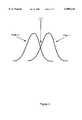
- FIG. 3are waveforms showing the operation of the wavelength locker in accordance with the present invention.
- FIG. 4is a block diagram of a second embodiment for monitoring and controlling multiple wavelengths in accordance with the present invention.
- FIGS. 5 and 6are graphs of laser response various wavelength for a wavelength locker without temperature compensation.
- FIG. 7depicts a system for monitoring a plurality of wavelengths without significantly disrupting the transmitted beam.
- the present inventionrelates to an improvement in monitoring and controlling wavelength, for example in a wavelength locker.
- the following descriptionis presented to enable one of ordinary skill in the art to make and use the invention and is provided in the context of a patent application and its requirements.
- Various modifications to the preferred embodimentwill be readily apparent to those skilled in the art and the generic principles herein may be applied to other embodiments.
- the present inventionis not intended to be limited to the embodiment shown but is to be accorded the widest scope limited to the embodiment shown but is to be accorded the widest scope consistent with the principles and features described herein.
- FIG. 1is a block diagram of a conventional system 10 for monitoring and controlling the wavelength of light in a wavelength locker.
- the light source 11is a distributed feedback Bragg reflective ("DFB") laser.
- the DFB laseris tuned to produce light of a predetermined wavelength. As the DFB laser 11 is used, the current generated in the cavity changes the characteristics of the cavity. Consequently, the wavelength of the light generated by the DFB laser 11 drifts from the predetermined wavelength as the DFB laser 11 is used.
- DFBdistributed feedback Bragg reflective
- Light from the DFB laser 11is then transmitted to collimator 12 and travels down the fiber 13.
- the beamis transmitted through the system 10 to the spectrum analyzer 18.
- the spectrum analyzer 18determines the wavelengths which comprise the beam of light transmitted through the fiber 17.
- the spectrum analyzer 18then feeds the information on the wavelength of the light produced to the feedback system 20.
- the feedback system 20uses this information to change the temperature of the DFB laser 11 to compensate for any drift in the wavelength of the light from the predetermined value.
- the system 10 shown in FIG. 1is capable of determining and controlling the wavelength of light produced by the DFB laser 11, those with ordinary skill in the art will realize that the system 10 disrupts the beam.
- the spectrum analyzer 18In order for the spectrum analyzer 18 to determine the wavelengths comprising the incoming light, the spectrum analyzer 18 is given access to the entire beam.
- the spectrum analyzer 18is bulky and expensive. Consequently, any conventional system 10 for monitoring controlling the wavelength of light in a wavelength locker will be costly and relatively large.
- the present inventionprovides for a method and system for monitoring and controlling the wavelength of light.
- the present inventionwill be described in terms of a wavelength locker using a DFB laser as a light source. However, one of ordinary skill in the art will readily recognize that this method and system will operate effectively for other types of lasers and other systems in which the wavelength of light must be monitored or controlled.
- FIG. 2depicting a block diagram of one embodiment 100 of such a system.
- the system 100includes a DFB laser 110 as a light source.
- the DFB laser 110is tuned to produce light of a predetermined wavelength, l 1 .
- the light from DFB laser 110travels through the collimator 120 to the diffractor 130.
- the diffractor 130diffracts light of a second predetermined wavelength,l 2 , in equal intensities through a predetermined angle t.
- the transmitted lightpasses to the collimator 180 for use in an application.
- Diffractor 130serves as a tap coupler. This tap coupler is insensitive to temperature, incoming wavelength and the state of the polarization. It is inherently insensitive to the temperature and to incoming wavelengths. It is insensitive to polarization because the incoming light is normal to the diffraction.
- the filters 140 and 142are placed at the predetermined angle t from the predetermined wavelength,l 2 .
- Filters 140 and 142could be, for example, bypass filters or they could be etalon filters.
- One of ordinary skill in the artwill readily recognize tht these filters could be a variety of types and still be utilzed within the spirit and scope of the present invention.
- approximately 94% of the light from DFB, for example, laser 110is transmitted to the collimator 180.
- approximately 3% of the lightis diffracted to each of the filters 140 and 142.
- Each filter 140 and 142has a photodiode, 150 and 152, respectively, placed to receive light transmitted by each filter 140 and 142.
- the filters and photodiodesare placed at the angle t from the direction of transmission to the collimator 180, when the DFB laser 110 produces light of wavelength l 1 , the intensity of light of wavelength l 2 at each filter 140 and 142 is equal. Thus, the intensity of light at each photodiode 150 and 152 and the signal from each photodiode 150 and 152 are equal.
- the intensity of the light having wavelength l 2differs at each filter 140 and 142.
- the intensity of light at each photodiode and the signal from each photodiode 150 and 152differs. This difference in intensity the of the light received by photodiodes 150 and 152 indicates the magnitude and direction of the drift in wavelength of the light produced by the DFB laser 110.
- the signals indicating the intensity of light received by photodiodes 150 and 152are sent to the differential amplifier 160.
- the differential amplifier 160calculates the difference in the signals from photodiodes 150 and 152.
- the difference in the intensity of light received by photodiodes 150 and 152indicates the magnitude and direction of the drift in wavelength of the light produced by the DFB laser 110.
- the difference in the signals from photodiodes 150 and 152also indicates the magnitude and direction, whether to higher or lower wavelengths, of the drift.
- the differential amplifier 160After calculating the difference in the signals, the differential amplifier 160 sends this difference to feedback circuit 170. In response to the signal from the differential amplifier 160, the feedback circuit 170 raises or lowers the temperature of the cavity of the DFB laser 110 as required to bring the wavelength of the light produced by the DFB laser 110 back to l 1 .
- the system 100 of FIG. 2requires significantly less disruption of the transmitted beam.
- the system 100is low cost and compact.
- the system of FIG. 2requires relatively little alignment.
- FIG. 3are waveforms showing the operation of the system of FIG. 2.
- ⁇ 1is representative of the wavelength that should be locked.
- FIG. 4shows a system 100' which includes a sensor arrangement.
- System 100'has similar elements to that of FIG. 2 but it also includes a sensor 153 for each of the photodiodes 150' and 152'.
- the sensorsare coupled to the differential amplifier 160' to allow the differential amplifier to modify the amplitude by the poles of the photodiodes. In so doing, the wavelength locker response is significantly improved.
- FIGS. 5 and 6are graphs of laser response versus wavelength for a wavelength locker without temperature compensation. As is seen the wavelength locker response is much more consistent with temperature compensation.
- FIG. 7depicts a system 200 for monitoring a plurality of wavelengths without significantly disrupting the transmitted beam.
- a plurality of diffractors 230-1 through 230-4is are placed in a beam of light.
- Each diffractor 230-1 through 230-4diffracts light of a predetermined wavelength,l 1 through l4, through a corresponding predetermined angle t1 through t4.
- Each diffractor, 230-1 through 230-4has two associated filters 240-1 through 240-4 and 242-1 through 242-4.
- Each set of filters 240-1 through 240-4 and 242-1 through 242-4are placed at angles of t1 through t4 from the transmitted beam.
- Each filter 240-1 through 240-4 and 242-1 through 242-1has a corresponding photodiode, 250-1 through 250-4 and 252-1 through 252-4.
- Each diffractor 230-1 through 230-4, its corresponding filters 240-1 through 240-4 and 242-1 through 242-4, and the associated photodiodes 250-1 through 250-4 and 252-1 through 252-4have the same function as the combination of the diffractor 130, the filters 140 and 142, and the photodiodes 150 and 152 of FIG. 2.
- the system 200can monitor four wavelengths. None prevents the construction of a system monitoring a different number of wavelengths.
- the signal from each photodiode, 250-1 through 250-4 and 252-1 through 252-4can be used to control a light source or other apparatus.
- a method and systemhas been disclosed for monitoring and controlling wavelength of a transmitted beam has disclosed. According to the method and system, the wavelength can be monitored and controlled with very little disruption of the transmitted beam. Also, if a temperature sensor arrangement is utilized a system and method in accordance with the present invention provides for consistent and accurate performance. In addition, the system and method are low in cost, compact, easy to manufacture, and require very little alignment.
Landscapes
- Physics & Mathematics (AREA)
- Spectroscopy & Molecular Physics (AREA)
- Electromagnetism (AREA)
- Engineering & Computer Science (AREA)
- Computer Networks & Wireless Communication (AREA)
- Signal Processing (AREA)
- General Physics & Mathematics (AREA)
- Semiconductor Lasers (AREA)
Abstract
Description
Claims (28)
Priority Applications (1)
| Application Number | Priority Date | Filing Date | Title |
|---|---|---|---|
| US08/816,089US6088142A (en) | 1997-03-13 | 1997-03-13 | System and method for precision wavelength monitoring |
Applications Claiming Priority (1)
| Application Number | Priority Date | Filing Date | Title |
|---|---|---|---|
| US08/816,089US6088142A (en) | 1997-03-13 | 1997-03-13 | System and method for precision wavelength monitoring |
Publications (1)
| Publication Number | Publication Date |
|---|---|
| US6088142Atrue US6088142A (en) | 2000-07-11 |
Family
ID=25219654
Family Applications (1)
| Application Number | Title | Priority Date | Filing Date |
|---|---|---|---|
| US08/816,089Expired - LifetimeUS6088142A (en) | 1997-03-13 | 1997-03-13 | System and method for precision wavelength monitoring |
Country Status (1)
| Country | Link |
|---|---|
| US (1) | US6088142A (en) |
Cited By (21)
| Publication number | Priority date | Publication date | Assignee | Title |
|---|---|---|---|---|
| WO2001011738A1 (en)* | 1999-08-10 | 2001-02-15 | Coretek, Inc. | Double etalon optical wavelength reference device |
| US6449077B1 (en)* | 1999-03-09 | 2002-09-10 | Agere Systems Guardian Corp. | Method and apparatus for electrically switching a wavelength control system |
| US6519068B1 (en)* | 1999-10-18 | 2003-02-11 | Agere Systems Inc. | Circuits and methods for achieving high signal-to-noise ratios and obtaining stabilized laser signals in dense wavelength division multiplexing systems |
| US6548805B1 (en)* | 2000-03-02 | 2003-04-15 | Litton Systems, Inc. | Method and system for detecting radiation |
| US6567433B2 (en) | 2000-10-10 | 2003-05-20 | Tunable Photonics Corporation | System and method for determining transmission wavelengths for lasers in a dense wavelength division multiplexer |
| US6584134B2 (en)* | 2000-01-21 | 2003-06-24 | Photonics Industries International, Inc. | High power laser |
| US6611341B2 (en) | 2000-10-10 | 2003-08-26 | Spectrasensors, Inc. | Method and system for locking transmission wavelengths for lasers in a dense wavelength division multiplexer utilizing a tunable etalon |
| US6633593B2 (en) | 2001-01-02 | 2003-10-14 | Spectrasensors, Inc. | Tunable semiconductor laser having cavity with wavelength selective mirror and Mach-Zehnder interferometer |
| US6671296B2 (en) | 2000-10-10 | 2003-12-30 | Spectrasensors, Inc. | Wavelength locker on optical bench and method of manufacture |
| WO2002075974A3 (en)* | 2001-03-19 | 2004-02-05 | Essex Corp | Wavelength stabilisation in optical communications systems |
| US6693928B2 (en) | 2000-10-10 | 2004-02-17 | Spectrasensors, Inc. | Technique for filtering chirp from optical signals |
| US6738140B2 (en) | 2000-09-19 | 2004-05-18 | Lambda Control, Inc. | Wavelength detector and method of detecting wavelength of an optical signal |
| US20050082524A1 (en)* | 2003-09-16 | 2005-04-21 | Yoshiki Kuhara | Optical receiver |
| US20050245939A1 (en)* | 2002-06-14 | 2005-11-03 | Joseph Ferrante | Device and methods for placing external fixation elements |
| WO2007083250A1 (en) | 2006-01-19 | 2007-07-26 | Philips Intellectual Property & Standards Gmbh | Color-controlled illumination device |
| WO2007082678A1 (en)* | 2006-01-13 | 2007-07-26 | Hottinger Baldwin Messtechnik Gmbh | Optical spectrometer |
| WO2008020841A1 (en)* | 2006-08-15 | 2008-02-21 | X-Rite, Incorporated | Sensing temperature of a light emitting diode |
| US20120155863A1 (en)* | 2009-08-21 | 2012-06-21 | Harald Rohde | Data Processing in an Optical Network |
| WO2018011063A1 (en)* | 2016-07-12 | 2018-01-18 | Blue Industry And Science | Process and device for characterising an optical source |
| US20190238235A1 (en)* | 2018-01-31 | 2019-08-01 | Nokia Solutions And Networks Oy | Optical burst monitoring |
| US11835760B1 (en)* | 2022-06-17 | 2023-12-05 | Taiwan Semiconductor Manufacturing Company Ltd. | Calibration system for wavelength-division multiplexing, wavelength-division multiplexing system, and calibrating method for wavelength-division multiplexing |
Citations (10)
| Publication number | Priority date | Publication date | Assignee | Title |
|---|---|---|---|---|
| US4168107A (en)* | 1978-03-30 | 1979-09-18 | Sperry Rand Corporation | Multimode optic device |
| US4485475A (en)* | 1983-05-27 | 1984-11-27 | The Mitre Corporation | Optical source peak wavelength control using a wavelength feedback network |
| US5029981A (en)* | 1988-09-17 | 1991-07-09 | Stc Plc | Diffraction grating |
| US5299045A (en)* | 1991-01-12 | 1994-03-29 | Canon Kabushiki Kaisha | Light detecting apparatus having a diffraction grating |
| US5410404A (en)* | 1993-11-30 | 1995-04-25 | The United States Of America As Represented By The Secretary Of The Navy | Fiber grating-based detection system for wavelength encoded fiber sensors |
| US5642448A (en)* | 1994-12-21 | 1997-06-24 | E-Tek Dynamics, Inc. | Integrable fiberoptic coupler and resulting devices and systems |
| US5646399A (en)* | 1995-08-28 | 1997-07-08 | Fujitsu Limited | Tunable optical filter having beam splitter and movable film filter |
| US5691989A (en)* | 1991-07-26 | 1997-11-25 | Accuwave Corporation | Wavelength stabilized laser sources using feedback from volume holograms |
| US5777763A (en)* | 1996-01-16 | 1998-07-07 | Bell Communications Research, Inc. | In-line optical wavelength reference and control module |
| US5818857A (en)* | 1997-03-05 | 1998-10-06 | Syncomm Inc. | Stabilized DFB laser |
- 1997
- 1997-03-13USUS08/816,089patent/US6088142A/ennot_activeExpired - Lifetime
Patent Citations (10)
| Publication number | Priority date | Publication date | Assignee | Title |
|---|---|---|---|---|
| US4168107A (en)* | 1978-03-30 | 1979-09-18 | Sperry Rand Corporation | Multimode optic device |
| US4485475A (en)* | 1983-05-27 | 1984-11-27 | The Mitre Corporation | Optical source peak wavelength control using a wavelength feedback network |
| US5029981A (en)* | 1988-09-17 | 1991-07-09 | Stc Plc | Diffraction grating |
| US5299045A (en)* | 1991-01-12 | 1994-03-29 | Canon Kabushiki Kaisha | Light detecting apparatus having a diffraction grating |
| US5691989A (en)* | 1991-07-26 | 1997-11-25 | Accuwave Corporation | Wavelength stabilized laser sources using feedback from volume holograms |
| US5410404A (en)* | 1993-11-30 | 1995-04-25 | The United States Of America As Represented By The Secretary Of The Navy | Fiber grating-based detection system for wavelength encoded fiber sensors |
| US5642448A (en)* | 1994-12-21 | 1997-06-24 | E-Tek Dynamics, Inc. | Integrable fiberoptic coupler and resulting devices and systems |
| US5646399A (en)* | 1995-08-28 | 1997-07-08 | Fujitsu Limited | Tunable optical filter having beam splitter and movable film filter |
| US5777763A (en)* | 1996-01-16 | 1998-07-07 | Bell Communications Research, Inc. | In-line optical wavelength reference and control module |
| US5818857A (en)* | 1997-03-05 | 1998-10-06 | Syncomm Inc. | Stabilized DFB laser |
Cited By (39)
| Publication number | Priority date | Publication date | Assignee | Title |
|---|---|---|---|---|
| US6449077B1 (en)* | 1999-03-09 | 2002-09-10 | Agere Systems Guardian Corp. | Method and apparatus for electrically switching a wavelength control system |
| US6498800B1 (en) | 1999-08-10 | 2002-12-24 | Coretek, Inc. | Double etalon optical wavelength reference device |
| WO2001011738A1 (en)* | 1999-08-10 | 2001-02-15 | Coretek, Inc. | Double etalon optical wavelength reference device |
| US6519068B1 (en)* | 1999-10-18 | 2003-02-11 | Agere Systems Inc. | Circuits and methods for achieving high signal-to-noise ratios and obtaining stabilized laser signals in dense wavelength division multiplexing systems |
| US6584134B2 (en)* | 2000-01-21 | 2003-06-24 | Photonics Industries International, Inc. | High power laser |
| US6548805B1 (en)* | 2000-03-02 | 2003-04-15 | Litton Systems, Inc. | Method and system for detecting radiation |
| US6738140B2 (en) | 2000-09-19 | 2004-05-18 | Lambda Control, Inc. | Wavelength detector and method of detecting wavelength of an optical signal |
| US6836330B2 (en) | 2000-09-19 | 2004-12-28 | Lambda Control, Inc. | Optical beamsplitter for a polarization insensitive wavelength detector and a polarization sensor |
| US6611341B2 (en) | 2000-10-10 | 2003-08-26 | Spectrasensors, Inc. | Method and system for locking transmission wavelengths for lasers in a dense wavelength division multiplexer utilizing a tunable etalon |
| US6671296B2 (en) | 2000-10-10 | 2003-12-30 | Spectrasensors, Inc. | Wavelength locker on optical bench and method of manufacture |
| US6693928B2 (en) | 2000-10-10 | 2004-02-17 | Spectrasensors, Inc. | Technique for filtering chirp from optical signals |
| US6714309B2 (en) | 2000-10-10 | 2004-03-30 | Spectrasensors, Inc. | Method and system for locking transmission wavelengths for lasers in a dense wavelength division multiplexer |
| US20060268948A1 (en)* | 2000-10-10 | 2006-11-30 | Spectrasensors, Inc., A Delaware Corporation | Laser wavelength locker |
| US6587484B1 (en) | 2000-10-10 | 2003-07-01 | Spectrasensor, Inc,. | Method and apparatus for determining transmission wavelengths for lasers in a dense wavelength division multiplexer |
| US7460567B2 (en) | 2000-10-10 | 2008-12-02 | Spectrasensors, Inc. | Laser wavelength locker |
| US6567433B2 (en) | 2000-10-10 | 2003-05-20 | Tunable Photonics Corporation | System and method for determining transmission wavelengths for lasers in a dense wavelength division multiplexer |
| US6633593B2 (en) | 2001-01-02 | 2003-10-14 | Spectrasensors, Inc. | Tunable semiconductor laser having cavity with wavelength selective mirror and Mach-Zehnder interferometer |
| US6690687B2 (en) | 2001-01-02 | 2004-02-10 | Spectrasensors, Inc. | Tunable semiconductor laser having cavity with ring resonator mirror and mach-zehnder interferometer |
| WO2002075974A3 (en)* | 2001-03-19 | 2004-02-05 | Essex Corp | Wavelength stabilisation in optical communications systems |
| US20050245939A1 (en)* | 2002-06-14 | 2005-11-03 | Joseph Ferrante | Device and methods for placing external fixation elements |
| US7366428B2 (en)* | 2003-09-16 | 2008-04-29 | Sumitomo Electric Indutries, Ltd. | Optical receiver |
| US20050082524A1 (en)* | 2003-09-16 | 2005-04-21 | Yoshiki Kuhara | Optical receiver |
| WO2007082678A1 (en)* | 2006-01-13 | 2007-07-26 | Hottinger Baldwin Messtechnik Gmbh | Optical spectrometer |
| KR101370368B1 (en)* | 2006-01-19 | 2014-03-05 | 코닌클리케 필립스 엔.브이. | Color-controlled illumination device |
| US20100158061A1 (en)* | 2006-01-19 | 2010-06-24 | Koninklijke Philips Electronics N.V. | Color-Controlled Illumination Device |
| US8022632B2 (en) | 2006-01-19 | 2011-09-20 | Koninklijke Philips Electronics N.V. | Color-controlled illumination device |
| WO2007083250A1 (en) | 2006-01-19 | 2007-07-26 | Philips Intellectual Property & Standards Gmbh | Color-controlled illumination device |
| CN101371114B (en)* | 2006-01-19 | 2012-11-14 | 皇家飞利浦电子股份有限公司 | Color-controlled illumination device |
| WO2008020841A1 (en)* | 2006-08-15 | 2008-02-21 | X-Rite, Incorporated | Sensing temperature of a light emitting diode |
| US20100128254A1 (en)* | 2006-08-15 | 2010-05-27 | Nisper Jon K | Sensing Temperature Of A Light Emitting Diode |
| US8274644B2 (en)* | 2006-08-15 | 2012-09-25 | X-Rite, Inc. | Sensing temperature of a light emitting diode |
| US20120155863A1 (en)* | 2009-08-21 | 2012-06-21 | Harald Rohde | Data Processing in an Optical Network |
| US8781318B2 (en)* | 2009-08-21 | 2014-07-15 | Xieon Networks S.A.R.L. | Data processing in an optical network |
| WO2018011063A1 (en)* | 2016-07-12 | 2018-01-18 | Blue Industry And Science | Process and device for characterising an optical source |
| FR3054034A1 (en)* | 2016-07-12 | 2018-01-19 | Blue Industry And Science | METHOD AND DEVICE FOR CHARACTERIZING AN OPTICAL SOURCE |
| US10768051B2 (en) | 2016-07-12 | 2020-09-08 | Blue Industry And Science | Process and device including a fixed cavity with a free spectral range for characterizing an optical source |
| US20190238235A1 (en)* | 2018-01-31 | 2019-08-01 | Nokia Solutions And Networks Oy | Optical burst monitoring |
| US11309973B2 (en)* | 2018-01-31 | 2022-04-19 | Nokia Solutions And Networks Oy | Optical burst monitoring |
| US11835760B1 (en)* | 2022-06-17 | 2023-12-05 | Taiwan Semiconductor Manufacturing Company Ltd. | Calibration system for wavelength-division multiplexing, wavelength-division multiplexing system, and calibrating method for wavelength-division multiplexing |
Similar Documents
| Publication | Publication Date | Title |
|---|---|---|
| US6088142A (en) | System and method for precision wavelength monitoring | |
| US6120190A (en) | Spatially variable bandpass filter monitoring and feedback control of laser wavelength especially in wavelength division multiplexing communication systems | |
| CA2209558C (en) | Wavelength monitoring and control assembly for wdm optical transmission systems | |
| US6389046B1 (en) | Method to sense laser array power and wavelength and reduce drift for wavelength selection and stabilization | |
| US5646762A (en) | Optical communication system using tandem Fabry-Perot etalon for wavelength selection | |
| US6349103B1 (en) | Cold-start wavelength-division-multiplexed optical transmission system | |
| US6868200B2 (en) | Wavelength division multiplexing optical transmission apparatus | |
| US5995275A (en) | Doped fiber amplifier using bidirectional pumping with pump lights having different frequencies | |
| US6034812A (en) | Gain equalizer and optical transmission system having the gain equalizer | |
| US7068949B2 (en) | Multi-wavelength locking method and apparatus for wavelength division multiplexing (WDM) optical communication system | |
| US5943152A (en) | Laser wavelength control device | |
| US6369926B1 (en) | Multichannel light source wavelength and strength stabilizing apparatus and method thereof | |
| US9515739B2 (en) | Mitigating noise and OBI in RFoG networks | |
| US6008915A (en) | Method of identifying faults in WDM optical networks | |
| EP1564915B1 (en) | Low relative intensity noise fiber grating type laser diode | |
| US5875273A (en) | Laser wavelength control under direct modulation | |
| US6963681B2 (en) | Automatic raman gain control | |
| US6404798B1 (en) | Low noise and wide power range laser source | |
| WO2001065734A2 (en) | Integrated optical monitoring system with tunable filter | |
| US20020149841A1 (en) | Raman excitation control method and optical transmission system using the same | |
| US7061596B2 (en) | Wavelength-tracking dispersion compensator | |
| US6714739B1 (en) | Optical transmission systems and optical receivers and receiving methods for use therein | |
| EP3185443B1 (en) | A wavelength division multiplexed telecommunication system with automatic compensation of chromatic dispersion | |
| US20050249505A1 (en) | Spectral tilt measurement system and method for an optical medium | |
| US6327064B1 (en) | Frequency stabilized and crosstalk-free signal sources for optical communication systems |
Legal Events
| Date | Code | Title | Description |
|---|---|---|---|
| AS | Assignment | Owner name:OPLINK COMMUNICATIONS, INC., CALIFORNIA Free format text:ASSIGNMENT OF ASSIGNORS INTEREST;ASSIGNORS:CAO, XIAOFAN;ZHENG, YU;REEL/FRAME:008578/0876;SIGNING DATES FROM 19970226 TO 19970227 | |
| STCF | Information on status: patent grant | Free format text:PATENTED CASE | |
| FPAY | Fee payment | Year of fee payment:4 | |
| FEPP | Fee payment procedure | Free format text:PAT HOLDER NO LONGER CLAIMS SMALL ENTITY STATUS, ENTITY STATUS SET TO UNDISCOUNTED (ORIGINAL EVENT CODE: STOL); ENTITY STATUS OF PATENT OWNER: LARGE ENTITY | |
| FEPP | Fee payment procedure | Free format text:PAYOR NUMBER ASSIGNED (ORIGINAL EVENT CODE: ASPN); ENTITY STATUS OF PATENT OWNER: LARGE ENTITY | |
| FPAY | Fee payment | Year of fee payment:8 | |
| REMI | Maintenance fee reminder mailed | ||
| FPAY | Fee payment | Year of fee payment:12 | |
| SULP | Surcharge for late payment | Year of fee payment:11 | |
| FEPP | Fee payment procedure | Free format text:PAYER NUMBER DE-ASSIGNED (ORIGINAL EVENT CODE: RMPN); ENTITY STATUS OF PATENT OWNER: LARGE ENTITY Free format text:PAYOR NUMBER ASSIGNED (ORIGINAL EVENT CODE: ASPN); ENTITY STATUS OF PATENT OWNER: LARGE ENTITY | |
| AS | Assignment | Owner name:OPLINK COMMUNICATIONS, LLC, CALIFORNIA Free format text:CHANGE OF NAME;ASSIGNOR:OPLINK COMMUNICATIONS, INC.;REEL/FRAME:041664/0579 Effective date:20150121 |