US6087983A - System for broadcasting GPS data to a pager - Google Patents
System for broadcasting GPS data to a pagerDownload PDFInfo
- Publication number
- US6087983A US6087983AUS09/357,577US35757799AUS6087983AUS 6087983 AUS6087983 AUS 6087983AUS 35757799 AUS35757799 AUS 35757799AUS 6087983 AUS6087983 AUS 6087983A
- Authority
- US
- United States
- Prior art keywords
- data
- gps
- section
- sections
- remote unit
- Prior art date
- Legal status (The legal status is an assumption and is not a legal conclusion. Google has not performed a legal analysis and makes no representation as to the accuracy of the status listed.)
- Expired - Lifetime
Links
- 238000004891communicationMethods0.000claimsabstractdescription70
- 238000000034methodMethods0.000claimsdescription19
- 230000005540biological transmissionEffects0.000abstractdescription6
- 238000010586diagramMethods0.000description9
- 230000008569processEffects0.000description8
- 238000005516engineering processMethods0.000description3
- 230000000737periodic effectEffects0.000description3
- 230000004044responseEffects0.000description3
- 230000011514reflexEffects0.000description2
- 230000001413cellular effectEffects0.000description1
- 230000008859changeEffects0.000description1
- 230000003247decreasing effectEffects0.000description1
- 230000001934delayEffects0.000description1
- 230000001419dependent effectEffects0.000description1
- 239000000284extractSubstances0.000description1
Images


Classifications
- G—PHYSICS
- G01—MEASURING; TESTING
- G01S—RADIO DIRECTION-FINDING; RADIO NAVIGATION; DETERMINING DISTANCE OR VELOCITY BY USE OF RADIO WAVES; LOCATING OR PRESENCE-DETECTING BY USE OF THE REFLECTION OR RERADIATION OF RADIO WAVES; ANALOGOUS ARRANGEMENTS USING OTHER WAVES
- G01S19/00—Satellite radio beacon positioning systems; Determining position, velocity or attitude using signals transmitted by such systems
- G01S19/01—Satellite radio beacon positioning systems transmitting time-stamped messages, e.g. GPS [Global Positioning System], GLONASS [Global Orbiting Navigation Satellite System] or GALILEO
- G01S19/03—Cooperating elements; Interaction or communication between different cooperating elements or between cooperating elements and receivers
- G01S19/07—Cooperating elements; Interaction or communication between different cooperating elements or between cooperating elements and receivers providing data for correcting measured positioning data, e.g. DGPS [differential GPS] or ionosphere corrections
- G01S19/071—DGPS corrections
- G—PHYSICS
- G01—MEASURING; TESTING
- G01S—RADIO DIRECTION-FINDING; RADIO NAVIGATION; DETERMINING DISTANCE OR VELOCITY BY USE OF RADIO WAVES; LOCATING OR PRESENCE-DETECTING BY USE OF THE REFLECTION OR RERADIATION OF RADIO WAVES; ANALOGOUS ARRANGEMENTS USING OTHER WAVES
- G01S19/00—Satellite radio beacon positioning systems; Determining position, velocity or attitude using signals transmitted by such systems
- G01S19/01—Satellite radio beacon positioning systems transmitting time-stamped messages, e.g. GPS [Global Positioning System], GLONASS [Global Orbiting Navigation Satellite System] or GALILEO
- G01S19/03—Cooperating elements; Interaction or communication between different cooperating elements or between cooperating elements and receivers
- G01S19/05—Cooperating elements; Interaction or communication between different cooperating elements or between cooperating elements and receivers providing aiding data
- G—PHYSICS
- G01—MEASURING; TESTING
- G01S—RADIO DIRECTION-FINDING; RADIO NAVIGATION; DETERMINING DISTANCE OR VELOCITY BY USE OF RADIO WAVES; LOCATING OR PRESENCE-DETECTING BY USE OF THE REFLECTION OR RERADIATION OF RADIO WAVES; ANALOGOUS ARRANGEMENTS USING OTHER WAVES
- G01S19/00—Satellite radio beacon positioning systems; Determining position, velocity or attitude using signals transmitted by such systems
- G01S19/01—Satellite radio beacon positioning systems transmitting time-stamped messages, e.g. GPS [Global Positioning System], GLONASS [Global Orbiting Navigation Satellite System] or GALILEO
- G01S19/03—Cooperating elements; Interaction or communication between different cooperating elements or between cooperating elements and receivers
- G01S19/09—Cooperating elements; Interaction or communication between different cooperating elements or between cooperating elements and receivers providing processing capability normally carried out by the receiver
- G—PHYSICS
- G01—MEASURING; TESTING
- G01S—RADIO DIRECTION-FINDING; RADIO NAVIGATION; DETERMINING DISTANCE OR VELOCITY BY USE OF RADIO WAVES; LOCATING OR PRESENCE-DETECTING BY USE OF THE REFLECTION OR RERADIATION OF RADIO WAVES; ANALOGOUS ARRANGEMENTS USING OTHER WAVES
- G01S19/00—Satellite radio beacon positioning systems; Determining position, velocity or attitude using signals transmitted by such systems
- G01S19/01—Satellite radio beacon positioning systems transmitting time-stamped messages, e.g. GPS [Global Positioning System], GLONASS [Global Orbiting Navigation Satellite System] or GALILEO
- G01S19/13—Receivers
- G01S19/24—Acquisition or tracking or demodulation of signals transmitted by the system
- G01S19/25—Acquisition or tracking or demodulation of signals transmitted by the system involving aiding data received from a cooperating element, e.g. assisted GPS
- G01S19/254—Acquisition or tracking or demodulation of signals transmitted by the system involving aiding data received from a cooperating element, e.g. assisted GPS relating to Doppler shift of satellite signals
- G—PHYSICS
- G01—MEASURING; TESTING
- G01S—RADIO DIRECTION-FINDING; RADIO NAVIGATION; DETERMINING DISTANCE OR VELOCITY BY USE OF RADIO WAVES; LOCATING OR PRESENCE-DETECTING BY USE OF THE REFLECTION OR RERADIATION OF RADIO WAVES; ANALOGOUS ARRANGEMENTS USING OTHER WAVES
- G01S19/00—Satellite radio beacon positioning systems; Determining position, velocity or attitude using signals transmitted by such systems
- G01S19/01—Satellite radio beacon positioning systems transmitting time-stamped messages, e.g. GPS [Global Positioning System], GLONASS [Global Orbiting Navigation Satellite System] or GALILEO
- G01S19/13—Receivers
- G01S19/24—Acquisition or tracking or demodulation of signals transmitted by the system
- G01S19/25—Acquisition or tracking or demodulation of signals transmitted by the system involving aiding data received from a cooperating element, e.g. assisted GPS
- G01S19/258—Acquisition or tracking or demodulation of signals transmitted by the system involving aiding data received from a cooperating element, e.g. assisted GPS relating to the satellite constellation, e.g. almanac, ephemeris data, lists of satellites in view
- G—PHYSICS
- G01—MEASURING; TESTING
- G01S—RADIO DIRECTION-FINDING; RADIO NAVIGATION; DETERMINING DISTANCE OR VELOCITY BY USE OF RADIO WAVES; LOCATING OR PRESENCE-DETECTING BY USE OF THE REFLECTION OR RERADIATION OF RADIO WAVES; ANALOGOUS ARRANGEMENTS USING OTHER WAVES
- G01S2205/00—Position-fixing by co-ordinating two or more direction or position line determinations; Position-fixing by co-ordinating two or more distance determinations
- G01S2205/001—Transmission of position information to remote stations
- G01S2205/008—Transmission of position information to remote stations using a mobile telephone network
- G—PHYSICS
- G01—MEASURING; TESTING
- G01S—RADIO DIRECTION-FINDING; RADIO NAVIGATION; DETERMINING DISTANCE OR VELOCITY BY USE OF RADIO WAVES; LOCATING OR PRESENCE-DETECTING BY USE OF THE REFLECTION OR RERADIATION OF RADIO WAVES; ANALOGOUS ARRANGEMENTS USING OTHER WAVES
- G01S5/00—Position-fixing by co-ordinating two or more direction or position line determinations; Position-fixing by co-ordinating two or more distance determinations
- G01S5/0009—Transmission of position information to remote stations
- G01S5/0045—Transmission from base station to mobile station
- G01S5/0063—Transmission from base station to mobile station of measured values, i.e. measurement on base station and position calculation on mobile
- G—PHYSICS
- G01—MEASURING; TESTING
- G01S—RADIO DIRECTION-FINDING; RADIO NAVIGATION; DETERMINING DISTANCE OR VELOCITY BY USE OF RADIO WAVES; LOCATING OR PRESENCE-DETECTING BY USE OF THE REFLECTION OR RERADIATION OF RADIO WAVES; ANALOGOUS ARRANGEMENTS USING OTHER WAVES
- G01S5/00—Position-fixing by co-ordinating two or more direction or position line determinations; Position-fixing by co-ordinating two or more distance determinations
- G01S5/0009—Transmission of position information to remote stations
- G01S5/009—Transmission of differential positioning data to mobile
Definitions
- the present inventionrelates to global positioning satellite (GPS) systems and, more particularly, to a system that uses a paging system to broadcast GPS aiding data.
- GPSglobal positioning satellite
- FIG. 1illustrates part of a conventional GPS system 10 that can be used to fix the position of a receiver 12, using satellites S 1 -S N .
- the receiver 12is able to receive the transmissions of those satellites that are "in view” (i.e., not blocked by the curvature of the earth).
- the receiver 12uses the arrival time differences between the received simultaneously transmitted signals, along with satellite Doppler and position data and other ephemeris data embedded in the simultaneously transmitted signals, to calculate the position of the receiver 12.
- GPS systemstypically assign unique pseudorandom sequences for each satellite in the system.
- the psuedorandom sequencesare repeated in each GPS satellite transmission at a set rate, and are used in determining pseudoranges (i.e., relative time delays between received satellite transmissions and a local clock in the receiver 12). The pseudoranges are then used in calculating the location of the receiver 12.
- reference GPS network systemsuse a reference GPS base station 20 that takes a snapshot of the GPS data, which is then sent to a remote unit (RU) 22.
- a reference GPS network systemtypically includes a large number of base stations.
- the reference GPS networkperforms some initial processing of the GPS signals received from the satellites.
- each reference GPS base stationreceives the satellite GPS signals via a GPS antenna 24.
- Data from the processed GPS signalsi.e., the aiding data
- the RU 22receives the processed GPS signals via the wireless link using an antenna 25.
- the RU 22also receives the GPS signals from the satellites using a GPS antenna 28. The RU 22 can then relatively quickly and accurately calculate its position using the received GPS signals from the satellites and the corresponding processed GPS data from the base station 20.
- One such conventional systemis disclosed in U.S. Pat. No. 5,663,734 issued to Krasner.
- a communications network for reference GPS network systemsis provided.
- the service areai.e., the geographical area to which GPS service is provided
- the communication networkincludes several communications base stations.
- the communications base stationsare separate from the reference GPS base stations. From the aiding data and the known locations of the sections, the communications network determines differential data corresponding to each section. The communications network then broadcasts the differential data and aiding data to the sections.
- the communications base stations in each sectionbroadcast the differential data with the unique code assigned to that section.
- Remote units requesting a location fixthen use the unique codes to extract the differential data corresponding to the section in which the remote unit is located.
- the accuracy of the pseudorange calculationsis increased and the processing load decreased by limiting the size of the sections.
- the communications networkperiodically broadcasts the differential data and aiding data as described above.
- This techniqueavoids the problem of some conventional systems that must receive and process location fix requests on an individual RU basis before the satellite data is transmitted to the RU.
- this aspect of the present inventionmore efficiently uses the available bandwidth of the communication system to service location fix requests.
- the continuous periodic broadcastsreduce latency in that the RU does not have to wait to receive the aiding data before calculating pseudoranges.
- FIG. 1is a simplified diagram of satellites and a receiver in a conventional GPS system.
- FIG. 2is a simplified functional block diagram illustrating a base station and remote unit of a conventional GPS system.
- FIG. 3is a diagram illustrating signal flow in a GPS communication link according to one embodiment of the present invention.
- FIG. 4is a diagram illustrating microzones in a subzone of a GPS communication link, according to one embodiment of the present invention.
- FIG. 5is a diagram illustrating the coding for the microzones of FIG. 4.
- FIG. 6is flow diagram illustrating the operation of one embodiment of the communications link of the present invention.
- FIG. 7is a block diagram illustrating a GPS communication system using a modified paging system, according to one embodiment of the present invention.
- FIG. 8is a flow diagram illustrating the operation of the system of FIG. 7.
- FIG. 3illustrates signal flow in a GPS communication network according to one embodiment of the present invention.
- the satellites S 1 -S Nperiodically broadcast the satellite data as in a conventional GPS system, which is received and processed by a reference GPS network (not shown) to determine the aiding data in the conventional manner.
- the communications base stations BS 1 -BS Mthen periodically broadcast the aiding data as in a conventional reference GPS network system, except that the aiding data includes differential data corresponding to each of a group of predefined sections in the service area.
- the communications networkis configured to determine the differential data. This is described below in conjunction with FIG. 5 for one particular type of embodiment. One embodiment of the communications network is described below in conjunction with FIG. 7.
- Each of the sections in the grouphas a unique predefined code.
- the codesare geographically Gray coded so that the codes of nearby sections only differ by small number of bits.
- the sectionshave a maximum width of about ten miles, although the size of the sections can vary trading off process load for section size. By limiting the size of the sections, the data processing load of the communications network can be optimized. It will be appreciated that as data processing technology progresses, the size of the sections may be increased.
- the communications networkreceives the aiding data from the conventional reference GPS network (not shown) and determines the differential data corresponding to each section.
- the communications base stations BS 1 -BS M of the communications networkthen broadcast the aiding data and differential data to all of the sections for reception by the RUs.
- the communications networkcauses the communications base stations located in a given section to broadcast the aiding data and the differential data along with the unique code assigned to that given section.
- the communications base stations in each sectionuse simulcast techniques to broadcast that particular section's resulting information. The broadcasted information is then received by RUs 31 1 -31 L .
- the RUscalculate pseudorange information and send the pseudorange information back to the communications network via the base stations BS 1 -BS M .
- This communications link between the RUs and the base stations BS 1 -BS Mis a two-way wireless link that can be implemented using any suitable technology.
- the communications linkcan be implemented using two-way paging system using the ReFLEX® protocol, cellular telephone, or other RF systems.
- the locations of each RUcan be calculated as in the aforementioned U.S. Pat. No. 5,663,734.
- FIG. 4illustrates an embodiment of the communications link in which the sections are implemented as microzones in a subzone of a paging system, according to one embodiment of the present invention.
- the service area of some conventional two-way paging systemsis divided into zones and subzones.
- the subzonesdefine simulcast regions in a simulcast paging system.
- Subzones in a typically conventional paging systemhave a width or size of up to about 150 miles and may vary in shape.
- the subzonesare divided into microzones.
- the subzoneshave a maximum size of about ten miles. As previously described, this size helps optimize data processing speed in the communications network.
- the exemplary subzone 40 in FIG. 4has three microzones 41-43. In light of this disclosure, those skilled in the art will appreciate that the subzones may have different numbers of microzones, and that the microzones may vary in size and shape.
- FIG. 5illustrates a table summarizing the coding for the microzones of a subzone. This embodiment is used when a two-way paging system provides the communications link between the communications base stations and the RUs.
- the communications base stations in the subzonewould broadcast the base data X 1 , along with the differential data ⁇ X 11 for a first microzone, the differential data ⁇ X 12 for a second microzone and ⁇ X 13 for a third microzone.
- the base datamay include the "base" Doppler shift corresponding to some central point in the subzone.
- the differential datawould then be the relative change of the Doppler data for some center point in the first microzone.
- the base Doppler shiftis 200 Hz and the Doppler shift of the first microzone is 205 Hz
- X 1would be 200 Hz while ⁇ X 11 would be +5 Hz.
- the communications base stations in the subzonewould broadcast the base data X 2 , along with the differential data ⁇ X 21 for the first microzone, the differential data ⁇ X 22 for the second microzone and ⁇ X 23 for the third microzone.
- the base data and differential data for the first, second and third microzonesare transmitted for each satellite S 1 -S N .
- each communications base station in the subzonebroadcasts the differential data for each microzone, along with the unique code assigned to the microzone in which the communications base station is located. This technique advantageously reduces the number of symbols or bits transmitted without loss of information, compared to broadcasting the Doppler shift corresponding to each microzone.
- FIG. 6illustrates how the communications network of the present invention is used in determining a location fix using a GPS system.
- the communications networkoperates as follows.
- the satellites S 1 -S Nperiodically broadcast GPS satellite data in the conventional manner.
- the communications networkreceives the satellite data using reference GPS network base stations (not shown) in a conventional manner.
- the reference GPS network(not shown) then processes the received satellite data to generate aiding data in the standard manner.
- the communications networkreceives the aiding data from the reference GPS network and performs further processing. In this embodiment, this processing includes determining the differential Doppler data for each section.
- the communications networkperiodically broadcasts the aiding data and differential data to the RUs 31 1 -31 L via the base stations BS 1 -BS M .
- Thisis different from the conventional reference GPS network systems that only transmit the aiding in response to individual location fix requests from a RU.
- the periodic broadcasting of the aiding data in the present inventionavoids the need for receiving and processing location fix requests from RUs before transmitting the aiding data, thereby increasing latency.
- the differential data and the unique code of the microzone in which each communications base station is locatedhelps ensure that the information is accurate for each particular section while helping to reduce the processing load of the RUs in calculation pseudoranges (described below). This process continuously repeats as indicated by an arrow 62A.
- a location fixis requested.
- the usercan request a location fix by pressing a button on the RU, in the conventional manner.
- the communications networkcan request a location fix of a particular RU by sending a command over the communications link, via the communications base stations BS 1 -BS M .
- the RUdetermines the pseudoranges using the aiding data and differential data it has received from the base stations BS 1 -BS M . More particularly, the RU will receive aiding data and differential data from transmissions from nearby base stations. These base stations will also include the unique code of the microzone in which the base stations are located.
- the RUthen combines the differential data corresponding to the microzone of the received code and the aiding data to calculate accurate pseudoranges. For example, the RU can calculate the pseudoranges from the combined aiding data as disclosed in the aforementioned U.S. Pat. No. 5,663,734.
- the RUtransmits the pseudoranges to the communications network via the communications base stations BS 1 -BS M .
- the communications networkthen calculates the location of the RU and transmits the location to the RU via the communications base stations BS 1 -BS M . The process then returns to performing the blocks 60-62 until the next RU location fix is requested.
- the communications networkcan transmit other information to the RU instead of or with the location information. For example, the communications network can transmit the location of the nearest gas station, bank, hospital, police station, etc. in response to a request transmitted by the user through the RU. This request would then be forwarded to the communications network via the base stations BS 1 -BS M .
- the processcan proceed from the block 64 to a block 68, as indicated by the dashed arrow 64A.
- the RUitself calculates its location using the pseudoranges. The process would then return to performing the blocks 60-62 until the next RU location fix is requested.
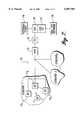
- FIG. 7illustrates a GPS communication system 70 using a modified paging system, according to one embodiment of the present invention.
- the system 70divides the service area into several subzones; i.e., subzone 1 through subzone Y.
- Each subzoneincludes several paging base stations.
- the paging base stationsare implemented using components that are commercially available from Glenayre Electronics, Inc., Charlotte, N.C. Of course, other suitable paging base stations or other types of wireless communications devices can be used in other embodiments.
- paging base stations 71 1 -71 Xare shown for subzone 1, with the base stations for subzone 2-subzone Y being omitted for clarity.
- the paging base stations of each subzoneare connected to a RF director (RFD).
- RFDRF director
- the RFD 73is implemented with a model GL3100 RFD (also available from Glenayre).
- a suitable standard linke.g., telephone lines, data lines, etc. is used to support communication between the RFD 73 and the paging base stations.
- the RFD 73is configured to handle RU registration, message scheduling and retransmissions.
- the RFD 73is connected to a paging switch (PS) 75, which is configured to provide access to the paging system and to manage the message traffic between the paging base stations and RFD and the rest of the communications network.
- PSpaging switch
- the PS 75is implemented with a model GL3000 messaging switch (also available from Glenayre), although other messaging switches can be used in alternative embodiments.
- the PS 75is connected to a location application gateway (LAG) 76.
- the LAG 76is configured to determine the location of the RU requesting a location fix, keeping track of the locations of the RUs, and providing an interface to external users.
- the LAG 76also provides an interface between the PS 75 (i.e., the paging system) and the processing end of the GPS system.
- the processing end of the GPS systemincludes the GPS location server (GPSLS) 77.
- the GPSLS 77extracts the ephemeris and Doppler data from the satellite data received by the base stations of a conventional reference GPS network 78.
- the GPSLS 77can determine the location of the RU instead of the LAG 76.
- the LAG 76 and GPSLS 77are each implemented using a computer system appropriately programmed.
- the functions of the LAG 76 and the GPSLS 77are combined in a single unit.
- the GPSLS 77receives differential GPS data and range correction information from the reference GPS network 78, which is extracted from the GPS signals.
- the GPSLS 77 and reference GPS network 78are implemented using technology available from SnapTrack, Inc., San Jose, Calif.
- An external user interface 79provides access for external user applications.
- the user applicationscan include location dependent traffic information, vehicle tracking, etc.
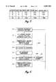
- FIG. 8is a flow diagram illustrating a location fix operation of the communication network 70 (FIG. 7).
- a location fixis determined as follows.
- a RU location fixis requested.
- a usercan request a location fix by pressing a button on the RU, or the communications network can request the location fix through the paging system.
- the RUcalculates the pseudoranges for the in view satellites using the aiding data and differential data broadcasted by the communications base stations.
- the RUrequests an inbound message transmission through the paging system to provide the pseudoranges to the communications network. This procedure is required in the ReFLEX® protocol.
- the RFD 73schedules the request and sends the schedule to the RU through the paging system.
- the RUtransmits the pseudoranges in the requested inbound message.
- the inbound messagealso includes other information needed for the location fix calculations, such as a time stamp.
- the RFD 73routes the inbound message to the PS 75.
- the PS 75routes the data to the LAG 76 in a block 90.
- the LAG 76requests the approximate location of the RU from the PS 75.
- the approximate location of the RUis the location of the communications base station that received the inbound message most strongly.
- the blocks 88-91may be replaced with a single block in which the RFD 73 automatically also passes the approximate location to the PS 75.
- the RFD 73may pass along all of the signal strengths of the communications base stations.
- the PS 75sends the approximate location to the LAG 76, which, in a block 94, sends the inbound data and the approximate location to the GPSLS 77.
- the PS 75may also route the approximate location along with the pseudorange information in the block 90.
- the GPSLS 77calculates the location of the RU using the data from the block 94 and data received from the reference GPS network 78 and sends the calculated location back to the LAG 76.
- the LAG 76sends the calculated location to the PS 75. The calculated location is then broadcast to the RU over the paging system in a block 99.
- the LAG 76may include other information along with the calculated location.
- the LAG 76may include the locations of other entities provided by the external user applications via the external users interface 79.
- the LAG 76may provide the calculated location to the external user application (e.g., a tracking application) via the external users interface 79.
Landscapes
- Engineering & Computer Science (AREA)
- Radar, Positioning & Navigation (AREA)
- Remote Sensing (AREA)
- Computer Networks & Wireless Communication (AREA)
- Physics & Mathematics (AREA)
- General Physics & Mathematics (AREA)
- Position Fixing By Use Of Radio Waves (AREA)
- Mobile Radio Communication Systems (AREA)
Abstract
Description
Claims (8)
Priority Applications (3)
| Application Number | Priority Date | Filing Date | Title |
|---|---|---|---|
| US09/357,577US6087983A (en) | 1999-07-20 | 1999-07-20 | System for broadcasting GPS data to a pager |
| AU76148/00AAU7614800A (en) | 1999-07-20 | 2000-09-20 | System for broadcasting gps data to a pager |
| PCT/US2000/026360WO2001022110A1 (en) | 1999-07-20 | 2000-09-20 | System for broadcasting gps data to a pager |
Applications Claiming Priority (1)
| Application Number | Priority Date | Filing Date | Title |
|---|---|---|---|
| US09/357,577US6087983A (en) | 1999-07-20 | 1999-07-20 | System for broadcasting GPS data to a pager |
Publications (1)
| Publication Number | Publication Date |
|---|---|
| US6087983Atrue US6087983A (en) | 2000-07-11 |
Family
ID=23406180
Family Applications (1)
| Application Number | Title | Priority Date | Filing Date |
|---|---|---|---|
| US09/357,577Expired - LifetimeUS6087983A (en) | 1999-07-20 | 1999-07-20 | System for broadcasting GPS data to a pager |
Country Status (3)
| Country | Link |
|---|---|
| US (1) | US6087983A (en) |
| AU (1) | AU7614800A (en) |
| WO (1) | WO2001022110A1 (en) |
Cited By (10)
| Publication number | Priority date | Publication date | Assignee | Title |
|---|---|---|---|---|
| WO2001048624A1 (en)* | 1999-12-29 | 2001-07-05 | Glorikian Harry A | An internet system for connecting client-travelers with geographically-associated data |
| US6567041B1 (en) | 2001-04-18 | 2003-05-20 | Sprint Spectrum, L.P. | Network system and method for a remote reference receiver system |
| US20040113794A1 (en)* | 1994-10-27 | 2004-06-17 | Dan Schlager | Self-locating personal alarm system equipped parachute |
| WO2007040375A1 (en) | 2005-10-06 | 2007-04-12 | Samsung Electronics Co., Ltd. | Method of acquiring initial gps signal in broadcasting system and system using the method |
| US20080218411A1 (en)* | 2004-06-29 | 2008-09-11 | Telefonaktiebolaget Lm Ericsson (Publ) | Assisted Satellite-Based Positioning |
| US20110018761A1 (en)* | 2009-07-24 | 2011-01-27 | John Walley | Method and system for a full gnss capable multi-standard single chip |
| US8060109B2 (en) | 1997-08-04 | 2011-11-15 | Enovsys Llc | Authorized location reporting mobile communication system |
| US20140184442A1 (en)* | 2012-12-28 | 2014-07-03 | Trimble Navigation Limited | Gnss receiver positioning system |
| US9602974B2 (en) | 2012-12-28 | 2017-03-21 | Trimble Inc. | Dead reconing system based on locally measured movement |
| US9880286B2 (en) | 2012-12-28 | 2018-01-30 | Trimble Inc. | Locally measured movement smoothing of position fixes based on extracted pseudoranges |
Families Citing this family (1)
| Publication number | Priority date | Publication date | Assignee | Title |
|---|---|---|---|---|
| CN112929833B (en)* | 2019-12-06 | 2022-05-06 | 中移(上海)信息通信科技有限公司 | Data distribution system and method |
Citations (17)
| Publication number | Priority date | Publication date | Assignee | Title |
|---|---|---|---|---|
| US3976995A (en)* | 1975-05-22 | 1976-08-24 | Sanders Associates, Inc. | Precessing display pager |
| US4752951A (en)* | 1985-12-23 | 1988-06-21 | Konneker Lloyd K | Method of providing location dependent person locator service |
| US5032845A (en)* | 1990-02-08 | 1991-07-16 | D.G.R., Inc. | Vehicle locating system with Loran-C |
| US5051741A (en)* | 1990-03-28 | 1991-09-24 | Wesby Philip B | Locating system |
| US5327486A (en)* | 1993-03-22 | 1994-07-05 | Bell Communications Research, Inc. | Method and system for managing telecommunications such as telephone calls |
| US5479408A (en)* | 1994-02-22 | 1995-12-26 | Will; Craig A. | Wireless personal paging, communications, and locating system |
| US5485163A (en)* | 1994-03-30 | 1996-01-16 | Motorola, Inc. | Personal locator system |
| US5506886A (en)* | 1993-12-27 | 1996-04-09 | Motorola, Inc. | Wide area paging with roaming subscriber units |
| US5515426A (en)* | 1994-02-28 | 1996-05-07 | Executone Information Systems, Inc. | Telephone communication system having a locator |
| US5625668A (en)* | 1994-04-12 | 1997-04-29 | Trimble Navigation Limited | Position reporting cellular telephone |
| US5663734A (en)* | 1995-10-09 | 1997-09-02 | Precision Tracking, Inc. | GPS receiver and method for processing GPS signals |
| US5682142A (en)* | 1994-07-29 | 1997-10-28 | Id Systems Inc. | Electronic control system/network |
| US5742907A (en)* | 1995-07-19 | 1998-04-21 | Ericsson Inc. | Automatic clear voice and land-line backup alignment for simulcast system |
| US5765112A (en)* | 1995-06-06 | 1998-06-09 | Flash Comm. Inc. | Low cost wide area network for data communication using outbound message specifying inbound message time and frequency |
| US5872539A (en)* | 1996-05-29 | 1999-02-16 | Hughes Electronics Corporation | Method and system for providing a user with precision location information |
| US5946626A (en)* | 1995-12-26 | 1999-08-31 | At&T Corp. | Method and system for determining location of subscriber of two-way paging service |
| US5952959A (en)* | 1995-01-25 | 1999-09-14 | American Technology Corporation | GPS relative position detection system |
- 1999
- 1999-07-20USUS09/357,577patent/US6087983A/ennot_activeExpired - Lifetime
- 2000
- 2000-09-20WOPCT/US2000/026360patent/WO2001022110A1/enactiveSearch and Examination
- 2000-09-20AUAU76148/00Apatent/AU7614800A/ennot_activeAbandoned
Patent Citations (17)
| Publication number | Priority date | Publication date | Assignee | Title |
|---|---|---|---|---|
| US3976995A (en)* | 1975-05-22 | 1976-08-24 | Sanders Associates, Inc. | Precessing display pager |
| US4752951A (en)* | 1985-12-23 | 1988-06-21 | Konneker Lloyd K | Method of providing location dependent person locator service |
| US5032845A (en)* | 1990-02-08 | 1991-07-16 | D.G.R., Inc. | Vehicle locating system with Loran-C |
| US5051741A (en)* | 1990-03-28 | 1991-09-24 | Wesby Philip B | Locating system |
| US5327486A (en)* | 1993-03-22 | 1994-07-05 | Bell Communications Research, Inc. | Method and system for managing telecommunications such as telephone calls |
| US5506886A (en)* | 1993-12-27 | 1996-04-09 | Motorola, Inc. | Wide area paging with roaming subscriber units |
| US5479408A (en)* | 1994-02-22 | 1995-12-26 | Will; Craig A. | Wireless personal paging, communications, and locating system |
| US5515426A (en)* | 1994-02-28 | 1996-05-07 | Executone Information Systems, Inc. | Telephone communication system having a locator |
| US5485163A (en)* | 1994-03-30 | 1996-01-16 | Motorola, Inc. | Personal locator system |
| US5625668A (en)* | 1994-04-12 | 1997-04-29 | Trimble Navigation Limited | Position reporting cellular telephone |
| US5682142A (en)* | 1994-07-29 | 1997-10-28 | Id Systems Inc. | Electronic control system/network |
| US5952959A (en)* | 1995-01-25 | 1999-09-14 | American Technology Corporation | GPS relative position detection system |
| US5765112A (en)* | 1995-06-06 | 1998-06-09 | Flash Comm. Inc. | Low cost wide area network for data communication using outbound message specifying inbound message time and frequency |
| US5742907A (en)* | 1995-07-19 | 1998-04-21 | Ericsson Inc. | Automatic clear voice and land-line backup alignment for simulcast system |
| US5663734A (en)* | 1995-10-09 | 1997-09-02 | Precision Tracking, Inc. | GPS receiver and method for processing GPS signals |
| US5946626A (en)* | 1995-12-26 | 1999-08-31 | At&T Corp. | Method and system for determining location of subscriber of two-way paging service |
| US5872539A (en)* | 1996-05-29 | 1999-02-16 | Hughes Electronics Corporation | Method and system for providing a user with precision location information |
Cited By (24)
| Publication number | Priority date | Publication date | Assignee | Title |
|---|---|---|---|---|
| US20040113794A1 (en)* | 1994-10-27 | 2004-06-17 | Dan Schlager | Self-locating personal alarm system equipped parachute |
| US8149112B2 (en) | 1994-10-27 | 2012-04-03 | Mosaid Technologies Incorporated | Multi-hazard alarm system using selectable power-level transmission and localization |
| US20080311882A1 (en)* | 1994-10-27 | 2008-12-18 | Zoltar Satellite Alarm Systems | Multi-hazard alarm system using selectable power-level transmission and localization |
| US8706078B2 (en) | 1997-08-04 | 2014-04-22 | Enovsys Llc | Location reporting satellite paging system with privacy feature |
| US8195188B2 (en) | 1997-08-04 | 2012-06-05 | Enovsys Llc | Location reporting satellite paging system with optional blocking of location reporting |
| US8060109B2 (en) | 1997-08-04 | 2011-11-15 | Enovsys Llc | Authorized location reporting mobile communication system |
| US8559942B2 (en) | 1997-08-04 | 2013-10-15 | Mundi Fomukong | Updating a mobile device's location |
| US20070083539A1 (en)* | 1999-12-29 | 2007-04-12 | Glorikian Harry A | Internet System for Connecting Client-Travelers with Geographically-Associated Data |
| US9299088B2 (en) | 1999-12-29 | 2016-03-29 | Cufer Asset Ltd. L.L.C. | Internet system for connecting client-travelers with geographically-associated data |
| WO2001048624A1 (en)* | 1999-12-29 | 2001-07-05 | Glorikian Harry A | An internet system for connecting client-travelers with geographically-associated data |
| US8725120B2 (en) | 1999-12-29 | 2014-05-13 | Crystal Development Consulting Services L.L.C. | Internet system for connecting client-travelers with geographically-associated data |
| US20020046259A1 (en)* | 1999-12-29 | 2002-04-18 | Glorikian Harry A. | Internet system for connecting client-travelers with geographically-associated data |
| US6567041B1 (en) | 2001-04-18 | 2003-05-20 | Sprint Spectrum, L.P. | Network system and method for a remote reference receiver system |
| US20080218411A1 (en)* | 2004-06-29 | 2008-09-11 | Telefonaktiebolaget Lm Ericsson (Publ) | Assisted Satellite-Based Positioning |
| EP1932255A4 (en)* | 2005-10-06 | 2012-02-29 | Samsung Electronics Co Ltd | METHOD FOR ACQUIRING A GPS SIGNAL IN A BROADCASTING SYSTEM AND USE |
| WO2007040375A1 (en) | 2005-10-06 | 2007-04-12 | Samsung Electronics Co., Ltd. | Method of acquiring initial gps signal in broadcasting system and system using the method |
| US8339311B2 (en) | 2009-07-24 | 2012-12-25 | Broadcom Corporation | Method and system for a full GNSS capable multi-standard single chip |
| EP2296012A1 (en)* | 2009-07-24 | 2011-03-16 | Broadcom Corporation | A method and system for a full GNSS capable multi-standard single chip |
| US20110018761A1 (en)* | 2009-07-24 | 2011-01-27 | John Walley | Method and system for a full gnss capable multi-standard single chip |
| US8912954B2 (en) | 2009-07-24 | 2014-12-16 | Broadcom Corporation | Method and system for a full GNSS capable multi-standard single chip |
| US20140184442A1 (en)* | 2012-12-28 | 2014-07-03 | Trimble Navigation Limited | Gnss receiver positioning system |
| US9602974B2 (en) | 2012-12-28 | 2017-03-21 | Trimble Inc. | Dead reconing system based on locally measured movement |
| US9612341B2 (en)* | 2012-12-28 | 2017-04-04 | Trimble Inc. | GNSS receiver positioning system |
| US9880286B2 (en) | 2012-12-28 | 2018-01-30 | Trimble Inc. | Locally measured movement smoothing of position fixes based on extracted pseudoranges |
Also Published As
| Publication number | Publication date |
|---|---|
| WO2001022110A1 (en) | 2001-03-29 |
| AU7614800A (en) | 2001-04-24 |
Similar Documents
| Publication | Publication Date | Title |
|---|---|---|
| AU751735B2 (en) | Satellite positioning system augmentation with wireless communication signals | |
| US6411254B1 (en) | Satellite positioning reference system and method | |
| CN1345481B (en) | Position reporting satellite paging system with position reporting selection blocking | |
| KR100610132B1 (en) | Method and apparatus for operating a satellite positioning system receiver | |
| US6215441B1 (en) | Satellite positioning reference system and method | |
| US7233798B2 (en) | Method and apparatus for determining location of a remote unit using GPS | |
| AU2003267224B2 (en) | Method and apparatus for improved location determination in a private radio network using a public network system | |
| RU2000112026A (en) | RECEIVER OF A GLOBAL POSITIONING SYSTEM WITH A LIMITED SPACE FOR FINDING A CODE SHIFT FOR A CELL PHONE SYSTEM | |
| US5423056A (en) | Adaptive cellular paging system | |
| US20110136508A1 (en) | Updating a Mobile Device's Location | |
| EP0501706A2 (en) | Adaptive cellular paging system and object location system | |
| US6087983A (en) | System for broadcasting GPS data to a pager | |
| CN100459730C (en) | System and method for aiding a location determination in a positioning system | |
| US6701153B1 (en) | Methods and systems for determining the location of mobiles in a UMTS telecommunications system | |
| CA2327719A1 (en) | Wireless position location system and method using differential global system information and general packet radio switching technology | |
| KR100594576B1 (en) | Location Tracking System and Method Using Region Segmentation | |
| JPH099339A (en) | Position measurement system using mobile communication system and call system for mobile communication system | |
| KR20030041657A (en) | Method for Automatically Providing Regional Weather Information using Mobile Communication Device | |
| KR100651613B1 (en) | Method and system for checking terminal location using paging channel | |
| AU2003246306B2 (en) | Satellite positioning reference system and method | |
| AU2004200563B2 (en) | Satellite positioning reference system and method | |
| HK1116871B (en) | Method and apparatus for operating a satellite positioning system receiver |
Legal Events
| Date | Code | Title | Description |
|---|---|---|---|
| AS | Assignment | Owner name:GLENAYRE ELECTRONICS, INC., NORTH CAROLINA Free format text:ASSIGNMENT OF ASSIGNORS INTEREST;ASSIGNORS:HO, DEREK;BUTERNOWSKY, BARRY D.;REEL/FRAME:010333/0422 Effective date:19990915 | |
| STCF | Information on status: patent grant | Free format text:PATENTED CASE | |
| FEPP | Fee payment procedure | Free format text:PAYOR NUMBER ASSIGNED (ORIGINAL EVENT CODE: ASPN); ENTITY STATUS OF PATENT OWNER: LARGE ENTITY | |
| FPAY | Fee payment | Year of fee payment:4 | |
| FPAY | Fee payment | Year of fee payment:8 | |
| SULP | Surcharge for late payment | Year of fee payment:7 | |
| AS | Assignment | Owner name:WI-LAN INC., CANADA Free format text:ASSIGNMENT OF ASSIGNORS INTEREST;ASSIGNOR:GLENAYRE ELECTRONICS, INC;REEL/FRAME:026627/0144 Effective date:20110630 | |
| FPAY | Fee payment | Year of fee payment:12 | |
| AS | Assignment | Owner name:QUARTERHILL INC., CANADA Free format text:MERGER AND CHANGE OF NAME;ASSIGNORS:WI-LAN INC.;QUARTERHILL INC.;REEL/FRAME:042902/0973 Effective date:20170601 | |
| AS | Assignment | Owner name:WI-LAN INC., CANADA Free format text:ASSIGNMENT OF ASSIGNORS INTEREST;ASSIGNOR:QUARTERHILL INC.;REEL/FRAME:043167/0149 Effective date:20170601 |