US6087743A - Position control system for use with micromechanical actuators - Google Patents
Position control system for use with micromechanical actuatorsDownload PDFInfo
- Publication number
- US6087743A US6087743AUS09/150,687US15068798AUS6087743AUS 6087743 AUS6087743 AUS 6087743AUS 15068798 AUS15068798 AUS 15068798AUS 6087743 AUS6087743 AUS 6087743A
- Authority
- US
- United States
- Prior art keywords
- movable element
- frequency
- oscillator
- coil
- variable oscillator
- Prior art date
- Legal status (The legal status is an assumption and is not a legal conclusion. Google has not performed a legal analysis and makes no representation as to the accuracy of the status listed.)
- Expired - Lifetime
Links
Images


Classifications
- H—ELECTRICITY
- H02—GENERATION; CONVERSION OR DISTRIBUTION OF ELECTRIC POWER
- H02K—DYNAMO-ELECTRIC MACHINES
- H02K33/00—Motors with reciprocating, oscillating or vibrating magnet, armature or coil system
- H02K33/02—Motors with reciprocating, oscillating or vibrating magnet, armature or coil system with armatures moved one way by energisation of a single coil system and returned by mechanical force, e.g. by springs
- H02K33/10—Motors with reciprocating, oscillating or vibrating magnet, armature or coil system with armatures moved one way by energisation of a single coil system and returned by mechanical force, e.g. by springs wherein the alternate energisation and de-energisation of the single coil system is effected or controlled by movement of the armatures
Definitions
- This inventionpertains generally to the field of positioners and actuators, particularly to micromechanical actuators, and to control devices for such actuators.
- Supplying a sufficient current to a drive coilswitches the movable element of the actuator to one of its terminal positions; it can be returned to its other terminal position either by use of a second coil which is alternately activated or by a spring which biases the movable element of the actuator to its normal stationary or latched position when current to the coil of the actuator is cut off.
- a micromechanical plunger supported by a springmay be drawn by the magnetic field from a drive coil, supplied with a selected level of current, to an intermediate position at which the spring return force is balanced by the magnetic attraction force from the drive coil. In order to provide sufficient positional accuracy for such a system, it is necessary to feed back a signal related to the displacement of the plunger to control the drive current to the coil so that the plunger reaches and remains at its desired commanded position.
- any sensing elements--coils or capacitors--mustnecessarily be quite small, so that the resistance of the element relative to its reactance is generally greater than would be found in sensing elements for larger mechanical systems.
- the relatively low Q factor for such micromechanical sensing systemsthus makes the use of resonant circuit detectors of the type used in large mechanical systems subject to unacceptably large errors in sensing accuracy.
- a simple, inexpensive, compact and high precision positioning systemis provided which is well suited for use with micromechanical actuators.
- the positioning systemallows the feedback control of the position of a moving element in a micromechanical actuator to move the element to a desired position within its range of movement, and to maintain the element at that position in the presence of disturbances.
- the positioning systemcan utilize low Q sensing coils to sense the position of the moving element while nonetheless providing precise positioning of the moving element.
- the position control system of the inventionincorporates the mechanical actuator system into a phase-locked loop which is synchronized to a signal from a reference oscillator at a selected reference frequency.
- a sensing coilis coupled to the movable element of the mechanical actuator system such that the effective inductance of the sensing coil changes with a change in position of the movable element.
- the sensing coilis part of a resonant tank circuit that controls the frequency of oscillation of a variable frequency oscillator.
- the output signal of the variable frequency oscillatoris compared in a phase detector with the reference oscillator signal, and the phase detector provides a pulsed output signal having a pulse duty cycle that is related to the phase or frequency difference. This output signal is provided as a drive signal to the drive coil of the actuator.
- the frequency of the output signal of the variable frequency oscillatormatches the reference oscillator frequency, and with a constant phase difference between the two signals, which results in power provided to the drive coil at a level such that the magnetic force applied by the drive coil is balanced by a restoring spring force so that the movable element is stationary.
- Any mechanical disturbance of the movable elemente.g., from external vibrations, results in a change of the phase difference between the variable oscillator signal and the reference oscillator signal, which serves to increase or decrease the duty cycle of the pulsed drive power to the drive coil as appropriate to move the movable element back to the desired position.
- the position of the movable elementcan be selectively changed, e.g., in a stepwise manner, by changing the frequency of the reference oscillator signal. If the movable element of the actuator is to be displaced to a new position, the output signal of the reference oscillator is changed to a frequency which is known to correspond to that position.
- a stepwise increase in the reference oscillator frequencyresults in a change in the output signal from the phase detector which is provided to the drive coil that reduces the magnetic field force on the movable element, allowing the spring to move the movable element in a direction to reduce the inductance of the sensing coil and thus increase the resonant frequency of the variable oscillator circuit until its frequency matches that of the reference oscillator.
- the difference in phase between the two oscillator signalsthen stabilizes at a new stationary position of the movable element.
- a stepwise decrease in the reference oscillator frequencyresults in a change in the output drive signal from the phase detector to the drive coil that increases the magnetic field from the drive coil, moving the mechanical system in a direction to increase the inductance of the sensing coil and lower the frequency of oscillation of the variable oscillator circuit until it matches the frequency of the reference oscillator.
- the movable elementthen stabilizes at a position at which there is constant phase difference between the reference oscillator signal and the variable oscillator signal.
- the positioning control circuit of the inventionmay be implemented using simple, inexpensive circuit components.
- the variable oscillator circuit that incorporates the sensing coilin particular, may be implemented as a simple positive feedback circuit using a conventional amplifier. Nonlinear feedback is provided in the oscillator circuit to limit oscillation growth. Incorporation of the sensing coil in the variable oscillator circuit in this manner provides a sensitive measure of moving element position that is relatively stable over time and with respect to changes in ambient temperature and component values.
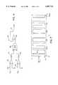
- FIG. 1is a perspective view of an exemplary micromechanical actuator incorporating the positioning system of the invention.
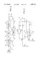
- FIG. 2is a block diagram of the micromechanical actuator and positioning system of the invention.
- FIG. 3is a schematic circuit diagram of a variable frequency oscillator that may be utilized in the present invention.
- FIG. 4is a schematic diagram of a phase detector circuit that may be utilized in the invention.
- FIGS. 5A-5Care exemplary waveforms of, respectively, the sinusoidal oscillator signals provided to the phase detector circuit of FIG. 4, the square wave outputs of the comparators in the circuit of FIG. 4, and the waveform of the phase detector output signal for such input signals.
- FIG. 6is a diagram illustrating the output signal duty cycle as a function of phase for the phase detector circuit of FIG. 4.
- FIG. 7is an exemplary waveform of the output signal of the phase detector circuit of FIG. 4 where the two oscillator input signals to the phase detector are at different frequencies.
- an exemplary mechanical actuator systemis shown generally at 10 in FIG. 1. It includes a magnetically actuated mechanical linear actuator 15 and a positioning system controller 16 which, as described further below, functions to sense the position of the movable element of the actuator 15 and to provide drive current to the actuator to control its position.
- the mechanical actuator 15 of FIG. 1may be formed, for example, as described in U.S. Pat. No. 5,644,177, and is shown for purposes of illustrating the invention only, it being understood that the present invention may be incorporated in any other suitable type of magnetically actuated mechanical actuator, and is particularly useful for micromechanical actuators.
- the actuator 15is formed on a substrate 21, which may have a generally planar top surface 22 as shown.
- the substrate 21may be formed of a variety of materials, including metals, plastics, ceramics, glasses, and semiconductors. Where electronic components are to be integrated with the actuator 15, it is preferable that the substrate 21 be a semiconductor, such as single crystal silicon.
- the actuator 15includes a fixed magnetic core 23 having two separate sections 24 formed on the surface 22 of the substrate 21. As illustrated in FIG.
- the core sections 24are formed generally in a planar fashion on the planar surface 22 of the substrate 21.
- a coil section 25has an upright mandrel 26 which forms part of the magnetic core.
- the mandrel 26has end sections 27 with pegs 28 formed thereon by which the mandrel engages the fixed sections 24 of the core formed on the substrate.
- Both the mandrel 26 and the fixed core sections 24are formed of a ferromagnetic metal, such as nickel, iron, or nickel-iron alloys.
- End faces 33 of the core sections 24are spaced from one another to define a gap into which a magnetic head 35 of an actuator plunger 36 extends.
- the plunger 36forms the movable element of the actuator.
- the plunger 36, or at least the head thereof,is also formed of a magnetic material, for example a ferromagnetic metal.
- the plunger 36is supported for linear movement by springs 37 which preferably provide a highly linear spring force.
- 1are rectangular type springs having a mounting section 38 on either side of the central body portion 39 of the actuator plunger 36, with openings 51 therein by which the springs are mounted to posts 50 extending from the substrate, outwardly extending sections 40 which join an outward end section 41, and inwardly extending sections 42 which extend from the end section 41 to join the plunger body 39.
- the spring sections 40, 41 and 42are free of the substrate 21 and thus can move as the plunger 36 moves.
- a sensing coil 55may be mounted, as shown in FIG. 1, on a mandrel 26' which is engaged to core sections 24' having end faces 33' adjacent to a head section 45 of the plunger 26.
- the ferromagnetic material of the head section 45is coupled to the sensing coil 55 so that the inductance of the sensing coil changes with the position of the plunger 28.
- the mandrel 26' and fixed core sections 24'may be formed in the same manner as the mandrel 26 and the core sections 24. As the plunger is drawn magnetically into the gap between the end faces 33 of the core sections 24, the head section 45 is moved into the gap between the end faces 33' to thus increase the effective inductance of the sensing coil 55.
- FIG. 2A block diagram of the components of the positioning system controller 16 as coupled to the actuator system 15 is shown in FIG. 2.
- the controller 16includes a variable oscillator circuit 57 to which the sensing coil 55 is connected by the lines 56.
- the variable oscillator circuit 57provides an output signal on a line 59 at a frequency ⁇ f to a phase detector 60.
- An adjustable frequency reference oscillator 61which may be any suitable oscillator, such as a commercially available adjustable frequency signal generator, provides an output signal on a line 62 to the phase detector 60 at a reference frequency ⁇ r .
- the phase detector 60provides a pulsed output signal on the lines 31 to the drive coil 30 with a pulse duty cycle that is related to the phase difference between the variable oscillator output signal and the reference oscillator output signal where the reference oscillator frequency ⁇ r and the variable oscillator frequency ⁇ f match each other.
- the phase detector 60provides a pulsed output signal that, as explained further below, has a pulse width that varies as a function of the difference between the frequencies of the two signals.
- the drive coil 30when supplied with the pulses of current provides corresponding pulses of magnetic force to move (or hold) the plunger 36 of the mechanical system 15. The displacement of the plunger affects the inductance of the sensing coil 55.
- the sensing coil 55forms part of a resonant tank circuit in the oscillator circuit 57 that determines the frequency of oscillation of the variable oscillator 57.
- the mechanical system 15can be controlled by control of the adjustable reference oscillator 61 by changing the frequency ⁇ r of the reference output signal on the lines 62 provided to the phase detector 60.
- the oscillator circuit 57comprises a high-gain operational amplifier 70 (e.g., a low cost video amplifier without an internal phase compensation circuit) with a positive feedback loop connected to the positive (non-inverting) input of the amplifier comprising a series resonant tank circuit including the sensing coil 55 (of equivalent inductance L and resistance R L ) and a capacitor 71 of capacitance C.
- a resistor R Brepresents the resistance path to ground in the positive feedback loop.
- a negative feedback loop connected to the negative (inverting) input of the operational amplifier 70includes a feedback resistor R 1 , a grounding resistor R 2 , and a second nonlinear feedback branch in parallel with the resistor R 1 comprised of a resistor R 5 and paralleled, oppositely conducting diodes D 1 and D 2 .
- the circuit of FIG. 1is a negative feedback loop connected to the negative (inverting) input of the operational amplifier 70 .
- R L /R BR 1 /R 2 , where R L and R B represent resistance in the positive feedback branch of the circuit and the ratio R 1 /R 2 determines the gain of the amplifier, or, stated equivalently, that the operational amplifier 70 supplies just enough power to compensate for the losses in the system to provide the unity gain required for sustained oscillation.
- the nonlinear feedback branchcomprised of the resistor R 5 and the diodes D 1 and D 2 is used to limit oscillation growth and to reduce sensitivity to small changes in component values.
- the value of R 1may be set slightly larger than that required for steady state oscillations so that very small signals near zero volts experience a positive exponential growth.
- FIG. 4A schematic diagram of an exemplary phase detector 60 is shown in FIG. 4.
- the phase detector circuit 60 of FIG. 4includes a first comparator 74, referenced to ground, which receives the reference oscillator signal on the line 62, and a second comparator 75, referenced to ground, which receives the variable oscillator signal on the line 59.
- the outputs of the comparators 74 and 75are provided (through diodes 77 and 78, respectively, to prevent negative potentials from being passed) to an exclusive OR (XOR) gate 80, the output of which is provided to a voltage follower operational amplifier 81.
- the circuit 60compares the reference frequency signal supplied on the line 62 to the feedback signal provided on the line 59 from the variable oscillator circuit.
- the output of the phase detector on the lines 31is a duty cycle modulated square wave which is used to power the actuator drive coil 30.
- the comparators 74 and 75convert the incoming sine waves on the lines 59 and 62 to square waves at the frequencies ⁇ r and ⁇ f of the reference oscillator and the variable oscillator, respectively.
- the output of the exclusive OR (XOR) gate 80will be in the logical high state when the inputs received from the comparators 74 and 75 are in different states, one high and one low, and will be low otherwise.
- the output of the XOR gate 80, as passed through the amplifier 81is a string of voltage pulses which are only high when the two input signals from the comparators 74 and 75 differ.
- the width of the pulses provided from the XOR gate 80is effectively the time lag between the reference oscillator signal on the line 62 and the variable oscillator signal on the line 59, and is directly proportional to the phase difference between these two signals when the signals are at the same frequency, as illustrated in FIGS. 5A-5C.
- FIG. 5Ashows the sine wave input signals 85 and 86 on the lines 62 and 59, respectively
- FIG. 5Bshows the corresponding outputs 88 and 89 of the comparators 74 and 75, respectively
- Fig. Cshows the output 90 of the XOR gate 80.
- the input signalsare either both positive or negative at all times, and the outputs of the comparators are identical, causing the pulse output signal 90 of the exclusive XOR gate 80 to be at a 0% duty cycle.
- the signals from the two comparatorsalways have different polarity, and the pulse output of the XOR gate goes to a 100° duty cycle.
- the duty cyclechanges as a triangle wave function 92 of the phase difference, as illustrated in FIG. 6.
- the mass of the plungeressentially low pass filters the pulses of force applied by the drive coil to the plunger to yield an effective steady state position in which the low pass filtered component of the magnetic force pulses applied to the plunger is balanced by the spring bias force.
- a separate low pass filter between the phase detector and drive coilmay be used to filter the signal provided to the drive coil, but because of the dynamics of the mechanical system 15 such a filter is generally not necessary.
- the exclusive OR gate 80produces a signal based on the effective phase ⁇ t between the two signals, ##EQU2## where ⁇ 0 is the effective phase at time t 0 . As long as the input frequencies differ, the integral will continue to change the value of the effective phase.
- the duty cycle of the pulse output 90 of the XOR gate 80will ramp from 0% to 100% and back at a rate determined by the difference of the two input frequencies, as illustrated in FIG. 7.
- the output signal 90as shown in FIG.
- the mass-spring system formed by the plunger 36 supported by the springs 37effectively follows this low frequency component so that the plunger would move periodically from 0% deflection to 100% deflection and back again if the input frequencies ⁇ r and ⁇ f continued to differ.
- the plungermoves, it effectively changes the inductance of the coil 55, and eventually the plunger reaches a position at which the frequencies ⁇ r and ⁇ f are the same, at which point frequency lock is attained.
- the plungerthen stabilizes at a position at which the phase lag between the reference oscillator signal and the variable oscillator signal produces a pulsed output 90 to the drive coil 30 with a pulse duty cycle that provides an effective DC component of magnetic force in the plunger to exactly balance the return force of the springs 37 at the new plunger position.
- phase detector circuit shown in FIG. 4is a very simple and inexpensive phase detector implementation, and is thus preferred. However, any appropriate phase and/or frequency lock circuit used in phase-locked loops could as well be utilized.
Landscapes
- Engineering & Computer Science (AREA)
- Power Engineering (AREA)
- Reciprocating, Oscillating Or Vibrating Motors (AREA)
Abstract
Description
Claims (10)
Priority Applications (1)
| Application Number | Priority Date | Filing Date | Title |
|---|---|---|---|
| US09/150,687US6087743A (en) | 1998-09-10 | 1998-09-10 | Position control system for use with micromechanical actuators |
Applications Claiming Priority (1)
| Application Number | Priority Date | Filing Date | Title |
|---|---|---|---|
| US09/150,687US6087743A (en) | 1998-09-10 | 1998-09-10 | Position control system for use with micromechanical actuators |
Publications (1)
| Publication Number | Publication Date |
|---|---|
| US6087743Atrue US6087743A (en) | 2000-07-11 |
Family
ID=22535592
Family Applications (1)
| Application Number | Title | Priority Date | Filing Date |
|---|---|---|---|
| US09/150,687Expired - LifetimeUS6087743A (en) | 1998-09-10 | 1998-09-10 | Position control system for use with micromechanical actuators |
Country Status (1)
| Country | Link |
|---|---|
| US (1) | US6087743A (en) |
Cited By (14)
| Publication number | Priority date | Publication date | Assignee | Title |
|---|---|---|---|---|
| US6607305B2 (en) | 2001-06-04 | 2003-08-19 | Wisconsin Alumni Research Foundation | Bi-directional micromechanical latching linear actuator |
| US20030155841A1 (en)* | 2002-02-21 | 2003-08-21 | Hirokazu Tamura | MEMS devices and methods for inhibiting errant motion of MEMS components |
| US20030156451A1 (en)* | 2002-02-21 | 2003-08-21 | Fitel Technologies, Inc. | MEMS devices and methods of manufacture |
| US20030155840A1 (en)* | 2002-02-21 | 2003-08-21 | Hirokazu Tamura | MEMS actuators |
| US6734665B2 (en)* | 2000-09-29 | 2004-05-11 | Balluff Gmbh | Inductive sensor having a sensor coil in the form of a structured conductive layer |
| US20050046659A1 (en)* | 1999-06-30 | 2005-03-03 | Kia Silverbrook | Method of detecting a fault condition in a micro-electromechanical device |
| US20050238506A1 (en)* | 2002-06-21 | 2005-10-27 | The Charles Stark Draper Laboratory, Inc. | Electromagnetically-actuated microfluidic flow regulators and related applications |
| US20060030837A1 (en)* | 2004-01-29 | 2006-02-09 | The Charles Stark Draper Laboratory, Inc. | Drug delivery apparatus |
| US20070120608A1 (en)* | 2005-11-28 | 2007-05-31 | Seagate Technology Llc | Capacitor detection by phase shift |
| US20080009836A1 (en)* | 2004-01-29 | 2008-01-10 | Jason Fiering | Drug delivery apparatus |
| US20080249510A1 (en)* | 2007-01-31 | 2008-10-09 | Mescher Mark J | Membrane-based fluid control in microfluidic devices |
| US20090072950A1 (en)* | 2007-07-30 | 2009-03-19 | Bae Systems Information And Electronic Systems Integration Inc. | Transponder with stabilized oscillator |
| US8876795B2 (en) | 2011-02-02 | 2014-11-04 | The Charles Stark Draper Laboratory, Inc. | Drug delivery apparatus |
| WO2017064353A1 (en)* | 2015-10-13 | 2017-04-20 | Sensapex Oy | Integrated measurement and micromechanical positioning apparatus for real-time test control |
Citations (21)
| Publication number | Priority date | Publication date | Assignee | Title |
|---|---|---|---|---|
| US3057195A (en)* | 1958-01-13 | 1962-10-09 | Systron Donner Corp | Force measuring system |
| US3074279A (en)* | 1963-01-22 | Position detecting transducer | ||
| US3102217A (en)* | 1960-02-01 | 1963-08-27 | Barber Coleman Company | Mechanically rebalanced condition control servosystem |
| US3182241A (en)* | 1961-09-08 | 1965-05-04 | Fischer & Porter Co | Measuring apparatus including a balancing servo system |
| US3457481A (en)* | 1966-06-27 | 1969-07-22 | Gen Electric | Force balance servo system in which the resonant circuit ambiguity is eliminated |
| US3461400A (en)* | 1967-08-30 | 1969-08-12 | Systron Donner Corp | Position detecting apparatus and method |
| US3541849A (en)* | 1968-05-08 | 1970-11-24 | James P Corbett | Oscillating crystal force transducer system |
| US3662595A (en)* | 1970-03-19 | 1972-05-16 | Bendix Corp | Oscillator type force measuring system insensitive to input voltage variations |
| US3944903A (en)* | 1973-01-16 | 1976-03-16 | Davy-Loewy Limited | Position transducer arrangement |
| US3970911A (en)* | 1973-06-29 | 1976-07-20 | Precitec Gmbh | Apparatus for distance control |
| US4021681A (en)* | 1976-01-22 | 1977-05-03 | Chrysler Corporation | Resonant sensor using a phase locked loop detector |
| US4810966A (en)* | 1983-07-05 | 1989-03-07 | Schmall Karl Heinz | Inductive sensor arrangement and measuring arrangement for use thereof |
| US5198764A (en)* | 1991-02-22 | 1993-03-30 | Sentech Corp. | Position detector apparatus and method utilizing a transient voltage waveform processor |
| US5381698A (en)* | 1992-04-06 | 1995-01-17 | Onicon Inc. | Flow-responsive apparatus |
| US5470043A (en)* | 1994-05-26 | 1995-11-28 | Lockheed Idaho Technologies Company | Magnetic latching solenoid |
| US5565722A (en)* | 1992-05-19 | 1996-10-15 | Forschungszentrum Julich Gmbh | Magnetic bearing control system |
| US5583290A (en)* | 1994-12-20 | 1996-12-10 | Analog Devices, Inc. | Micromechanical apparatus with limited actuation bandwidth |
| US5602411A (en)* | 1994-04-28 | 1997-02-11 | Siemens Aktiengesellschaft | Micromechanical component with a dielectric movable structure, and microsystem |
| US5644177A (en)* | 1995-02-23 | 1997-07-01 | Wisconsin Alumni Research Foundation | Micromechanical magnetically actuated devices |
| US5767672A (en)* | 1995-09-08 | 1998-06-16 | Schneider Electric Sa | Inductive proximity sensor for detecting magnetic and non-magnetic metallic objects |
| US5808384A (en)* | 1997-06-05 | 1998-09-15 | Wisconsin Alumni Research Foundation | Single coil bistable, bidirectional micromechanical actuator |
- 1998
- 1998-09-10USUS09/150,687patent/US6087743A/ennot_activeExpired - Lifetime
Patent Citations (21)
| Publication number | Priority date | Publication date | Assignee | Title |
|---|---|---|---|---|
| US3074279A (en)* | 1963-01-22 | Position detecting transducer | ||
| US3057195A (en)* | 1958-01-13 | 1962-10-09 | Systron Donner Corp | Force measuring system |
| US3102217A (en)* | 1960-02-01 | 1963-08-27 | Barber Coleman Company | Mechanically rebalanced condition control servosystem |
| US3182241A (en)* | 1961-09-08 | 1965-05-04 | Fischer & Porter Co | Measuring apparatus including a balancing servo system |
| US3457481A (en)* | 1966-06-27 | 1969-07-22 | Gen Electric | Force balance servo system in which the resonant circuit ambiguity is eliminated |
| US3461400A (en)* | 1967-08-30 | 1969-08-12 | Systron Donner Corp | Position detecting apparatus and method |
| US3541849A (en)* | 1968-05-08 | 1970-11-24 | James P Corbett | Oscillating crystal force transducer system |
| US3662595A (en)* | 1970-03-19 | 1972-05-16 | Bendix Corp | Oscillator type force measuring system insensitive to input voltage variations |
| US3944903A (en)* | 1973-01-16 | 1976-03-16 | Davy-Loewy Limited | Position transducer arrangement |
| US3970911A (en)* | 1973-06-29 | 1976-07-20 | Precitec Gmbh | Apparatus for distance control |
| US4021681A (en)* | 1976-01-22 | 1977-05-03 | Chrysler Corporation | Resonant sensor using a phase locked loop detector |
| US4810966A (en)* | 1983-07-05 | 1989-03-07 | Schmall Karl Heinz | Inductive sensor arrangement and measuring arrangement for use thereof |
| US5198764A (en)* | 1991-02-22 | 1993-03-30 | Sentech Corp. | Position detector apparatus and method utilizing a transient voltage waveform processor |
| US5381698A (en)* | 1992-04-06 | 1995-01-17 | Onicon Inc. | Flow-responsive apparatus |
| US5565722A (en)* | 1992-05-19 | 1996-10-15 | Forschungszentrum Julich Gmbh | Magnetic bearing control system |
| US5602411A (en)* | 1994-04-28 | 1997-02-11 | Siemens Aktiengesellschaft | Micromechanical component with a dielectric movable structure, and microsystem |
| US5470043A (en)* | 1994-05-26 | 1995-11-28 | Lockheed Idaho Technologies Company | Magnetic latching solenoid |
| US5583290A (en)* | 1994-12-20 | 1996-12-10 | Analog Devices, Inc. | Micromechanical apparatus with limited actuation bandwidth |
| US5644177A (en)* | 1995-02-23 | 1997-07-01 | Wisconsin Alumni Research Foundation | Micromechanical magnetically actuated devices |
| US5767672A (en)* | 1995-09-08 | 1998-06-16 | Schneider Electric Sa | Inductive proximity sensor for detecting magnetic and non-magnetic metallic objects |
| US5808384A (en)* | 1997-06-05 | 1998-09-15 | Wisconsin Alumni Research Foundation | Single coil bistable, bidirectional micromechanical actuator |
Non-Patent Citations (6)
| Title |
|---|
| H. Guckel, et al., "Electromagnetic Linear Actuators with Inductive Position Sensing," Sensors and Actuators, vol. A53, 1996, pp. 386-391, (Month Unknown). |
| H. Guckel, et al., Electromagnetic Linear Actuators with Inductive Position Sensing, Sensors and Actuators, vol. A53, 1996, pp. 386 391, (Month Unknown).* |
| S. Suzuki, et al., "Semiconductor Capacitance-Type Accelerometer with PWM Electrostatic Servo Technique," Sensors and Actuators, vol. A21-23, 1990, pp. 316-319. (Month Unknown). |
| S. Suzuki, et al., Semiconductor Capacitance Type Accelerometer with PWM Electrostatic Servo Technique, Sensors and Actuators, vol. A21 23, 1990, pp. 316 319. (Month Unknown).* |
| T. Earles, et al., "Magnetic Microactuators for Relay Applications," Proc. of Actuator 96, 5th International Conference on New Actuators, Jun. 26-28, 1996, Bremen, Germany, pp. 132-135. |
| T. Earles, et al., Magnetic Microactuators for Relay Applications, Proc. of Actuator 96, 5 th International Conference on New Actuators, Jun. 26 28, 1996, Bremen, Germany, pp. 132 135.* |
Cited By (38)
| Publication number | Priority date | Publication date | Assignee | Title |
|---|---|---|---|---|
| US6969142B2 (en)* | 1999-06-30 | 2005-11-29 | Silverbrook Research, Pty Ltd | Method of detecting a fault condition in a micro-electromechanical device |
| US20100073429A1 (en)* | 1999-06-30 | 2010-03-25 | Silverbrook Research Pty Ltd | Inkjet Nozzle Device With Cantilevered Actuating Arm |
| US20080211875A1 (en)* | 1999-06-30 | 2008-09-04 | Silverbrook Research Pty Ltd | Inkjet nozzle device with cantilevered actuating arm |
| US8038252B2 (en) | 1999-06-30 | 2011-10-18 | Silverbrook Research Pty Ltd | Method of detecting MEM device faults with single current pulse |
| US7210666B2 (en) | 1999-06-30 | 2007-05-01 | Silverbrook Research Pty Ltd | Fluid ejection device with inner and outer arms |
| US7635177B2 (en) | 1999-06-30 | 2009-12-22 | Silverbrook Research Pty Ltd | Inkjet nozzle device with cantilevered actuating arm |
| US7128093B2 (en) | 1999-06-30 | 2006-10-31 | Silverbrook Research Pty Ltd | MEMS fluid ejection device configured for detecting a fault condition |
| US20060130904A1 (en)* | 1999-06-30 | 2006-06-22 | Silverbrook Research Pty Ltd | Fluid ejection device with inner and outer arms |
| US20050046659A1 (en)* | 1999-06-30 | 2005-03-03 | Kia Silverbrook | Method of detecting a fault condition in a micro-electromechanical device |
| US8317301B2 (en) | 1999-06-30 | 2012-11-27 | Zamtec Limited | Printing nozzle arrangement having fault detector |
| US20050275492A1 (en)* | 1999-06-30 | 2005-12-15 | Silverbrook Research Pty Ltd | Mems fluid ejection device configured for detecting a fault condition |
| US6734665B2 (en)* | 2000-09-29 | 2004-05-11 | Balluff Gmbh | Inductive sensor having a sensor coil in the form of a structured conductive layer |
| US6607305B2 (en) | 2001-06-04 | 2003-08-19 | Wisconsin Alumni Research Foundation | Bi-directional micromechanical latching linear actuator |
| US6900510B2 (en) | 2002-02-21 | 2005-05-31 | Advanced Microsensors | MEMS devices and methods for inhibiting errant motion of MEMS components |
| US6858911B2 (en) | 2002-02-21 | 2005-02-22 | Advanced Micriosensors | MEMS actuators |
| US6812055B2 (en) | 2002-02-21 | 2004-11-02 | Advanced Microsensors | MEMS devices and methods of manufacture |
| US6717227B2 (en) | 2002-02-21 | 2004-04-06 | Advanced Microsensors | MEMS devices and methods of manufacture |
| US20030155840A1 (en)* | 2002-02-21 | 2003-08-21 | Hirokazu Tamura | MEMS actuators |
| US20030156451A1 (en)* | 2002-02-21 | 2003-08-21 | Fitel Technologies, Inc. | MEMS devices and methods of manufacture |
| US20030155841A1 (en)* | 2002-02-21 | 2003-08-21 | Hirokazu Tamura | MEMS devices and methods for inhibiting errant motion of MEMS components |
| US20050238506A1 (en)* | 2002-06-21 | 2005-10-27 | The Charles Stark Draper Laboratory, Inc. | Electromagnetically-actuated microfluidic flow regulators and related applications |
| US20080009836A1 (en)* | 2004-01-29 | 2008-01-10 | Jason Fiering | Drug delivery apparatus |
| US9180054B2 (en) | 2004-01-29 | 2015-11-10 | The Charles Stark Draper Laboratory, Inc. | Drug delivery apparatus |
| US7867193B2 (en) | 2004-01-29 | 2011-01-11 | The Charles Stark Draper Laboratory, Inc. | Drug delivery apparatus |
| US7867194B2 (en) | 2004-01-29 | 2011-01-11 | The Charles Stark Draper Laboratory, Inc. | Drug delivery apparatus |
| US20060030837A1 (en)* | 2004-01-29 | 2006-02-09 | The Charles Stark Draper Laboratory, Inc. | Drug delivery apparatus |
| US20070120608A1 (en)* | 2005-11-28 | 2007-05-31 | Seagate Technology Llc | Capacitor detection by phase shift |
| US7710205B2 (en)* | 2005-11-28 | 2010-05-04 | Seagate Technology Llc | Capacitor detection by phase shift |
| US9651166B2 (en) | 2007-01-31 | 2017-05-16 | The Charles Stark Draper Laboratory, Inc. | Membrane-based fluid control in microfluidic devices |
| US9046192B2 (en) | 2007-01-31 | 2015-06-02 | The Charles Stark Draper Laboratory, Inc. | Membrane-based fluid control in microfluidic devices |
| US20080249510A1 (en)* | 2007-01-31 | 2008-10-09 | Mescher Mark J | Membrane-based fluid control in microfluidic devices |
| US7970357B2 (en)* | 2007-07-30 | 2011-06-28 | Bae Systems Information And Electronic Systems Integration Inc. | Transponder with stabilized oscillator |
| US20090072950A1 (en)* | 2007-07-30 | 2009-03-19 | Bae Systems Information And Electronic Systems Integration Inc. | Transponder with stabilized oscillator |
| US8876795B2 (en) | 2011-02-02 | 2014-11-04 | The Charles Stark Draper Laboratory, Inc. | Drug delivery apparatus |
| US9764121B2 (en) | 2011-02-02 | 2017-09-19 | The Charles Stark Draper Laboratory, Inc. | Drug delivery apparatus |
| WO2017064353A1 (en)* | 2015-10-13 | 2017-04-20 | Sensapex Oy | Integrated measurement and micromechanical positioning apparatus for real-time test control |
| US20190077024A1 (en)* | 2015-10-13 | 2019-03-14 | Sensapex Oy | Integrated measurement and micromechanical positioning apparatus for real-time test control |
| US10828785B2 (en)* | 2015-10-13 | 2020-11-10 | Sensapex Oy | Integrated measurement and micromechanical positioning apparatus for real-time test control |
Similar Documents
| Publication | Publication Date | Title |
|---|---|---|
| US6087743A (en) | Position control system for use with micromechanical actuators | |
| Seeger et al. | Charge control of parallel-plate, electrostatic actuators and the tip-in instability | |
| EP3105853B1 (en) | A drive circuitry for a mems resonator | |
| US5442288A (en) | Magnetoelastic magnetometer | |
| US5641911A (en) | Method and apparatus for feedback-control of an asymmetric differential pressure transducer | |
| US6079272A (en) | Gyroscopes and compensation | |
| US3973191A (en) | Inductive displacement sensor apparatus | |
| EP1666834B1 (en) | Position and electromagnetic field sensor | |
| US20110133488A1 (en) | Electromechanical Generator for, and Method of, Converting Mechanical Vibrational Energy Into Electrical Energy | |
| US11121662B2 (en) | Closed loop resonance tracking using phase matching | |
| WO2011154785A2 (en) | Position sensor | |
| US4644570A (en) | Sensor amplification and enhancement apparatus using digital techniques | |
| EP0239333A2 (en) | Wide bandwidth linear motor system | |
| US6150811A (en) | Magnetic field sensor for stable magnetic field measurement over a wide temperature range | |
| JPS633674A (en) | Controller for motor of reciprocal movement | |
| Csencsics et al. | Design of a phase-locked-loop-based control scheme for lissajous-trajectory scanning of fast steering mirrors | |
| CA1078211A (en) | Servoed linear accelerometer | |
| EP1066533B1 (en) | Apparatus for improving performance of a force balance accelerometer based on a single-coil velocity geophone | |
| Tapson et al. | Improved capacitance measurement by means of resonance locking | |
| US4112345A (en) | Stepping motor with energizing circuit | |
| US4123735A (en) | Induction-type meter for measuring mechanical quantities | |
| CN101375496A (en) | Impedance adjusting circuit | |
| EP0663065B1 (en) | Position sensors | |
| Zhong et al. | Digital charge control for reducing nonlinearity in fast steering mirrors driven by piezoelectric actuators | |
| Krawat et al. | A Lorentz Force Magnetometer with 600 nT/√ Hz Resolution over a Bandwidth of 480 Hz utilizing Force Feedback and CMOS Readout Electronics |
Legal Events
| Date | Code | Title | Description |
|---|---|---|---|
| AS | Assignment | Owner name:NAVY, SECRETARY OF THE, UNITED STATES OF AMERICA O Free format text:CONFIRMATORY LICENSE;ASSIGNOR:WISCONSIN ALUMNI RESEARCH FOUNDATION;REEL/FRAME:009759/0225 Effective date:19981010 | |
| AS | Assignment | Owner name:WISCONSIN ALUMNI RESEARCH FOUNDATION, WISCONSIN Free format text:ASSIGNMENT OF ASSIGNORS INTEREST;ASSIGNORS:GUCKEL, HENRY;STIERS, ERIC W.;REEL/FRAME:009886/0848 Effective date:19990318 | |
| AS | Assignment | Owner name:AIR FORCE, UNITED STATES, OHIO Free format text:ASSIGNMENT OF ASSIGNORS INTEREST;ASSIGNOR:WISCONSIN ALUMNI RESEARCH FOUNDATION;REEL/FRAME:009945/0311 Effective date:19990406 | |
| STCF | Information on status: patent grant | Free format text:PATENTED CASE | |
| AS | Assignment | Owner name:ENERGY, U.S. DEPARTMENT OF, DISTRICT OF COLUMBIA Free format text:CONFIRMATORY LICENSE;ASSIGNOR:UNIVERSITY OF WISCONSIN-WISCONSIN ALUMNI RESEARCH FOUNDATION;REEL/FRAME:014467/0073 Effective date:19981016 | |
| FEPP | Fee payment procedure | Free format text:PAT HOLDER CLAIMS SMALL ENTITY STATUS, ENTITY STATUS SET TO SMALL (ORIGINAL EVENT CODE: LTOS); ENTITY STATUS OF PATENT OWNER: SMALL ENTITY | |
| FEPP | Fee payment procedure | Free format text:PAYOR NUMBER ASSIGNED (ORIGINAL EVENT CODE: ASPN); ENTITY STATUS OF PATENT OWNER: SMALL ENTITY | |
| FPAY | Fee payment | Year of fee payment:4 | |
| FPAY | Fee payment | Year of fee payment:8 | |
| SULP | Surcharge for late payment | Year of fee payment:7 | |
| FPAY | Fee payment | Year of fee payment:12 |