US6086614A - Orthopedic prosthesis having anti-backout screw - Google Patents
Orthopedic prosthesis having anti-backout screwDownload PDFInfo
- Publication number
- US6086614A US6086614AUS09/012,500US1250098AUS6086614AUS 6086614 AUS6086614 AUS 6086614AUS 1250098 AUS1250098 AUS 1250098AUS 6086614 AUS6086614 AUS 6086614A
- Authority
- US
- United States
- Prior art keywords
- screw
- splines
- head
- shoulder
- bore
- Prior art date
- Legal status (The legal status is an assumption and is not a legal conclusion. Google has not performed a legal analysis and makes no representation as to the accuracy of the status listed.)
- Expired - Lifetime
Links
Images


Classifications
- A—HUMAN NECESSITIES
- A61—MEDICAL OR VETERINARY SCIENCE; HYGIENE
- A61F—FILTERS IMPLANTABLE INTO BLOOD VESSELS; PROSTHESES; DEVICES PROVIDING PATENCY TO, OR PREVENTING COLLAPSING OF, TUBULAR STRUCTURES OF THE BODY, e.g. STENTS; ORTHOPAEDIC, NURSING OR CONTRACEPTIVE DEVICES; FOMENTATION; TREATMENT OR PROTECTION OF EYES OR EARS; BANDAGES, DRESSINGS OR ABSORBENT PADS; FIRST-AID KITS
- A61F2/00—Filters implantable into blood vessels; Prostheses, i.e. artificial substitutes or replacements for parts of the body; Appliances for connecting them with the body; Devices providing patency to, or preventing collapsing of, tubular structures of the body, e.g. stents
- A61F2/02—Prostheses implantable into the body
- A61F2/30—Joints
- A61F2/38—Joints for elbows or knees
- A61F2/3859—Femoral components
- A—HUMAN NECESSITIES
- A61—MEDICAL OR VETERINARY SCIENCE; HYGIENE
- A61B—DIAGNOSIS; SURGERY; IDENTIFICATION
- A61B17/00—Surgical instruments, devices or methods
- A61B17/56—Surgical instruments or methods for treatment of bones or joints; Devices specially adapted therefor
- A61B17/58—Surgical instruments or methods for treatment of bones or joints; Devices specially adapted therefor for osteosynthesis, e.g. bone plates, screws or setting implements
- A61B17/68—Internal fixation devices, including fasteners and spinal fixators, even if a part thereof projects from the skin
- A61B17/80—Cortical plates, i.e. bone plates; Instruments for holding or positioning cortical plates, or for compressing bones attached to cortical plates
- A61B17/8033—Cortical plates, i.e. bone plates; Instruments for holding or positioning cortical plates, or for compressing bones attached to cortical plates having indirect contact with screw heads, or having contact with screw heads maintained with the aid of additional components, e.g. nuts, wedges or head covers
- A61B17/8047—Cortical plates, i.e. bone plates; Instruments for holding or positioning cortical plates, or for compressing bones attached to cortical plates having indirect contact with screw heads, or having contact with screw heads maintained with the aid of additional components, e.g. nuts, wedges or head covers wherein the additional element surrounds the screw head in the plate hole
- A—HUMAN NECESSITIES
- A61—MEDICAL OR VETERINARY SCIENCE; HYGIENE
- A61B—DIAGNOSIS; SURGERY; IDENTIFICATION
- A61B17/00—Surgical instruments, devices or methods
- A61B17/56—Surgical instruments or methods for treatment of bones or joints; Devices specially adapted therefor
- A61B17/58—Surgical instruments or methods for treatment of bones or joints; Devices specially adapted therefor for osteosynthesis, e.g. bone plates, screws or setting implements
- A61B17/68—Internal fixation devices, including fasteners and spinal fixators, even if a part thereof projects from the skin
- A61B17/80—Cortical plates, i.e. bone plates; Instruments for holding or positioning cortical plates, or for compressing bones attached to cortical plates
- A61B17/8052—Cortical plates, i.e. bone plates; Instruments for holding or positioning cortical plates, or for compressing bones attached to cortical plates immobilised relative to screws by interlocking form of the heads and plate holes, e.g. conical or threaded
- A—HUMAN NECESSITIES
- A61—MEDICAL OR VETERINARY SCIENCE; HYGIENE
- A61F—FILTERS IMPLANTABLE INTO BLOOD VESSELS; PROSTHESES; DEVICES PROVIDING PATENCY TO, OR PREVENTING COLLAPSING OF, TUBULAR STRUCTURES OF THE BODY, e.g. STENTS; ORTHOPAEDIC, NURSING OR CONTRACEPTIVE DEVICES; FOMENTATION; TREATMENT OR PROTECTION OF EYES OR EARS; BANDAGES, DRESSINGS OR ABSORBENT PADS; FIRST-AID KITS
- A61F2/00—Filters implantable into blood vessels; Prostheses, i.e. artificial substitutes or replacements for parts of the body; Appliances for connecting them with the body; Devices providing patency to, or preventing collapsing of, tubular structures of the body, e.g. stents
- A61F2/02—Prostheses implantable into the body
- A61F2/30—Joints
- A61F2002/30001—Additional features of subject-matter classified in A61F2/28, A61F2/30 and subgroups thereof
- A61F2002/30108—Shapes
- A61F2002/3011—Cross-sections or two-dimensional shapes
- A61F2002/30138—Convex polygonal shapes
- A61F2002/30143—Convex polygonal shapes hexagonal
- A—HUMAN NECESSITIES
- A61—MEDICAL OR VETERINARY SCIENCE; HYGIENE
- A61F—FILTERS IMPLANTABLE INTO BLOOD VESSELS; PROSTHESES; DEVICES PROVIDING PATENCY TO, OR PREVENTING COLLAPSING OF, TUBULAR STRUCTURES OF THE BODY, e.g. STENTS; ORTHOPAEDIC, NURSING OR CONTRACEPTIVE DEVICES; FOMENTATION; TREATMENT OR PROTECTION OF EYES OR EARS; BANDAGES, DRESSINGS OR ABSORBENT PADS; FIRST-AID KITS
- A61F2/00—Filters implantable into blood vessels; Prostheses, i.e. artificial substitutes or replacements for parts of the body; Appliances for connecting them with the body; Devices providing patency to, or preventing collapsing of, tubular structures of the body, e.g. stents
- A61F2/02—Prostheses implantable into the body
- A61F2/30—Joints
- A61F2002/30001—Additional features of subject-matter classified in A61F2/28, A61F2/30 and subgroups thereof
- A61F2002/30316—The prosthesis having different structural features at different locations within the same prosthesis; Connections between prosthetic parts; Special structural features of bone or joint prostheses not otherwise provided for
- A61F2002/30329—Connections or couplings between prosthetic parts, e.g. between modular parts; Connecting elements
- A61F2002/30331—Connections or couplings between prosthetic parts, e.g. between modular parts; Connecting elements made by longitudinally pushing a protrusion into a complementarily-shaped recess, e.g. held by friction fit
- A61F2002/30332—Conically- or frustoconically-shaped protrusion and recess
- A—HUMAN NECESSITIES
- A61—MEDICAL OR VETERINARY SCIENCE; HYGIENE
- A61F—FILTERS IMPLANTABLE INTO BLOOD VESSELS; PROSTHESES; DEVICES PROVIDING PATENCY TO, OR PREVENTING COLLAPSING OF, TUBULAR STRUCTURES OF THE BODY, e.g. STENTS; ORTHOPAEDIC, NURSING OR CONTRACEPTIVE DEVICES; FOMENTATION; TREATMENT OR PROTECTION OF EYES OR EARS; BANDAGES, DRESSINGS OR ABSORBENT PADS; FIRST-AID KITS
- A61F2/00—Filters implantable into blood vessels; Prostheses, i.e. artificial substitutes or replacements for parts of the body; Appliances for connecting them with the body; Devices providing patency to, or preventing collapsing of, tubular structures of the body, e.g. stents
- A61F2/02—Prostheses implantable into the body
- A61F2/30—Joints
- A61F2002/30001—Additional features of subject-matter classified in A61F2/28, A61F2/30 and subgroups thereof
- A61F2002/30316—The prosthesis having different structural features at different locations within the same prosthesis; Connections between prosthetic parts; Special structural features of bone or joint prostheses not otherwise provided for
- A61F2002/30329—Connections or couplings between prosthetic parts, e.g. between modular parts; Connecting elements
- A61F2002/30433—Connections or couplings between prosthetic parts, e.g. between modular parts; Connecting elements using additional screws, bolts, dowels, rivets or washers e.g. connecting screws
- A—HUMAN NECESSITIES
- A61—MEDICAL OR VETERINARY SCIENCE; HYGIENE
- A61F—FILTERS IMPLANTABLE INTO BLOOD VESSELS; PROSTHESES; DEVICES PROVIDING PATENCY TO, OR PREVENTING COLLAPSING OF, TUBULAR STRUCTURES OF THE BODY, e.g. STENTS; ORTHOPAEDIC, NURSING OR CONTRACEPTIVE DEVICES; FOMENTATION; TREATMENT OR PROTECTION OF EYES OR EARS; BANDAGES, DRESSINGS OR ABSORBENT PADS; FIRST-AID KITS
- A61F2/00—Filters implantable into blood vessels; Prostheses, i.e. artificial substitutes or replacements for parts of the body; Appliances for connecting them with the body; Devices providing patency to, or preventing collapsing of, tubular structures of the body, e.g. stents
- A61F2/02—Prostheses implantable into the body
- A61F2/30—Joints
- A61F2002/30001—Additional features of subject-matter classified in A61F2/28, A61F2/30 and subgroups thereof
- A61F2002/30316—The prosthesis having different structural features at different locations within the same prosthesis; Connections between prosthetic parts; Special structural features of bone or joint prostheses not otherwise provided for
- A61F2002/30329—Connections or couplings between prosthetic parts, e.g. between modular parts; Connecting elements
- A61F2002/30476—Connections or couplings between prosthetic parts, e.g. between modular parts; Connecting elements locked by an additional locking mechanism
- A61F2002/305—Snap connection
- A—HUMAN NECESSITIES
- A61—MEDICAL OR VETERINARY SCIENCE; HYGIENE
- A61F—FILTERS IMPLANTABLE INTO BLOOD VESSELS; PROSTHESES; DEVICES PROVIDING PATENCY TO, OR PREVENTING COLLAPSING OF, TUBULAR STRUCTURES OF THE BODY, e.g. STENTS; ORTHOPAEDIC, NURSING OR CONTRACEPTIVE DEVICES; FOMENTATION; TREATMENT OR PROTECTION OF EYES OR EARS; BANDAGES, DRESSINGS OR ABSORBENT PADS; FIRST-AID KITS
- A61F2/00—Filters implantable into blood vessels; Prostheses, i.e. artificial substitutes or replacements for parts of the body; Appliances for connecting them with the body; Devices providing patency to, or preventing collapsing of, tubular structures of the body, e.g. stents
- A61F2/02—Prostheses implantable into the body
- A61F2/30—Joints
- A61F2002/30001—Additional features of subject-matter classified in A61F2/28, A61F2/30 and subgroups thereof
- A61F2002/30316—The prosthesis having different structural features at different locations within the same prosthesis; Connections between prosthetic parts; Special structural features of bone or joint prostheses not otherwise provided for
- A61F2002/30329—Connections or couplings between prosthetic parts, e.g. between modular parts; Connecting elements
- A61F2002/30518—Connections or couplings between prosthetic parts, e.g. between modular parts; Connecting elements with possibility of relative movement between the prosthetic parts
- A61F2002/3052—Connections or couplings between prosthetic parts, e.g. between modular parts; Connecting elements with possibility of relative movement between the prosthetic parts unrestrained in only one direction, e.g. moving unidirectionally
- A—HUMAN NECESSITIES
- A61—MEDICAL OR VETERINARY SCIENCE; HYGIENE
- A61F—FILTERS IMPLANTABLE INTO BLOOD VESSELS; PROSTHESES; DEVICES PROVIDING PATENCY TO, OR PREVENTING COLLAPSING OF, TUBULAR STRUCTURES OF THE BODY, e.g. STENTS; ORTHOPAEDIC, NURSING OR CONTRACEPTIVE DEVICES; FOMENTATION; TREATMENT OR PROTECTION OF EYES OR EARS; BANDAGES, DRESSINGS OR ABSORBENT PADS; FIRST-AID KITS
- A61F2/00—Filters implantable into blood vessels; Prostheses, i.e. artificial substitutes or replacements for parts of the body; Appliances for connecting them with the body; Devices providing patency to, or preventing collapsing of, tubular structures of the body, e.g. stents
- A61F2/02—Prostheses implantable into the body
- A61F2/30—Joints
- A61F2/30767—Special external or bone-contacting surface, e.g. coating for improving bone ingrowth
- A61F2/30771—Special external or bone-contacting surface, e.g. coating for improving bone ingrowth applied in original prostheses, e.g. holes or grooves
- A61F2002/30795—Blind bores, e.g. of circular cross-section
- A61F2002/30797—Blind bores, e.g. of circular cross-section internally-threaded
- A—HUMAN NECESSITIES
- A61—MEDICAL OR VETERINARY SCIENCE; HYGIENE
- A61F—FILTERS IMPLANTABLE INTO BLOOD VESSELS; PROSTHESES; DEVICES PROVIDING PATENCY TO, OR PREVENTING COLLAPSING OF, TUBULAR STRUCTURES OF THE BODY, e.g. STENTS; ORTHOPAEDIC, NURSING OR CONTRACEPTIVE DEVICES; FOMENTATION; TREATMENT OR PROTECTION OF EYES OR EARS; BANDAGES, DRESSINGS OR ABSORBENT PADS; FIRST-AID KITS
- A61F2/00—Filters implantable into blood vessels; Prostheses, i.e. artificial substitutes or replacements for parts of the body; Appliances for connecting them with the body; Devices providing patency to, or preventing collapsing of, tubular structures of the body, e.g. stents
- A61F2/02—Prostheses implantable into the body
- A61F2/30—Joints
- A61F2/30767—Special external or bone-contacting surface, e.g. coating for improving bone ingrowth
- A61F2/30771—Special external or bone-contacting surface, e.g. coating for improving bone ingrowth applied in original prostheses, e.g. holes or grooves
- A61F2002/30878—Special external or bone-contacting surface, e.g. coating for improving bone ingrowth applied in original prostheses, e.g. holes or grooves with non-sharp protrusions, for instance contacting the bone for anchoring, e.g. keels, pegs, pins, posts, shanks, stems, struts
- A—HUMAN NECESSITIES
- A61—MEDICAL OR VETERINARY SCIENCE; HYGIENE
- A61F—FILTERS IMPLANTABLE INTO BLOOD VESSELS; PROSTHESES; DEVICES PROVIDING PATENCY TO, OR PREVENTING COLLAPSING OF, TUBULAR STRUCTURES OF THE BODY, e.g. STENTS; ORTHOPAEDIC, NURSING OR CONTRACEPTIVE DEVICES; FOMENTATION; TREATMENT OR PROTECTION OF EYES OR EARS; BANDAGES, DRESSINGS OR ABSORBENT PADS; FIRST-AID KITS
- A61F2/00—Filters implantable into blood vessels; Prostheses, i.e. artificial substitutes or replacements for parts of the body; Appliances for connecting them with the body; Devices providing patency to, or preventing collapsing of, tubular structures of the body, e.g. stents
- A61F2/02—Prostheses implantable into the body
- A61F2/30—Joints
- A61F2/46—Special tools for implanting artificial joints
- A61F2/4637—Special tools for implanting artificial joints for connecting or disconnecting two parts of a prosthesis
- A61F2002/4638—Tools for performing screwing, e.g. nut or screwdrivers, or particular adaptations therefor
- A—HUMAN NECESSITIES
- A61—MEDICAL OR VETERINARY SCIENCE; HYGIENE
- A61F—FILTERS IMPLANTABLE INTO BLOOD VESSELS; PROSTHESES; DEVICES PROVIDING PATENCY TO, OR PREVENTING COLLAPSING OF, TUBULAR STRUCTURES OF THE BODY, e.g. STENTS; ORTHOPAEDIC, NURSING OR CONTRACEPTIVE DEVICES; FOMENTATION; TREATMENT OR PROTECTION OF EYES OR EARS; BANDAGES, DRESSINGS OR ABSORBENT PADS; FIRST-AID KITS
- A61F2220/00—Fixations or connections for prostheses classified in groups A61F2/00 - A61F2/26 or A61F2/82 or A61F9/00 or A61F11/00 or subgroups thereof
- A61F2220/0025—Connections or couplings between prosthetic parts, e.g. between modular parts; Connecting elements
- A61F2220/0033—Connections or couplings between prosthetic parts, e.g. between modular parts; Connecting elements made by longitudinally pushing a protrusion into a complementary-shaped recess, e.g. held by friction fit
- A—HUMAN NECESSITIES
- A61—MEDICAL OR VETERINARY SCIENCE; HYGIENE
- A61F—FILTERS IMPLANTABLE INTO BLOOD VESSELS; PROSTHESES; DEVICES PROVIDING PATENCY TO, OR PREVENTING COLLAPSING OF, TUBULAR STRUCTURES OF THE BODY, e.g. STENTS; ORTHOPAEDIC, NURSING OR CONTRACEPTIVE DEVICES; FOMENTATION; TREATMENT OR PROTECTION OF EYES OR EARS; BANDAGES, DRESSINGS OR ABSORBENT PADS; FIRST-AID KITS
- A61F2220/00—Fixations or connections for prostheses classified in groups A61F2/00 - A61F2/26 or A61F2/82 or A61F9/00 or A61F11/00 or subgroups thereof
- A61F2220/0025—Connections or couplings between prosthetic parts, e.g. between modular parts; Connecting elements
- A61F2220/0041—Connections or couplings between prosthetic parts, e.g. between modular parts; Connecting elements using additional screws, bolts, dowels or rivets, e.g. connecting screws
- A—HUMAN NECESSITIES
- A61—MEDICAL OR VETERINARY SCIENCE; HYGIENE
- A61F—FILTERS IMPLANTABLE INTO BLOOD VESSELS; PROSTHESES; DEVICES PROVIDING PATENCY TO, OR PREVENTING COLLAPSING OF, TUBULAR STRUCTURES OF THE BODY, e.g. STENTS; ORTHOPAEDIC, NURSING OR CONTRACEPTIVE DEVICES; FOMENTATION; TREATMENT OR PROTECTION OF EYES OR EARS; BANDAGES, DRESSINGS OR ABSORBENT PADS; FIRST-AID KITS
- A61F2230/00—Geometry of prostheses classified in groups A61F2/00 - A61F2/26 or A61F2/82 or A61F9/00 or A61F11/00 or subgroups thereof
- A61F2230/0002—Two-dimensional shapes, e.g. cross-sections
- A61F2230/0017—Angular shapes
Definitions
- the present inventionrelates generally to implantable prostheses for replacing human skeletal joints, and relates more particularly to an anti-backout screw for use with an implantable prosthesis.
- Implantable orthopedic prosthesesin one form, comprise manufactured replacements for the ends and articulating surfaces of the bones of the skeleton. Such prostheses are implanted to repair or reconstruct all or part of an articulating skeletal joint that is functioning abnormally due to disease, trauma, or congenital defect.
- the knee jointis often treated with such prostheses.
- the knee jointis a major weight bearing joint and degenerates more quickly than some other joints in case of abnormality. Also, the knee joint plays a critical role in ambulation and quality of life, resulting in great demand for surgical correction of abnormalities.
- the human knee jointinvolves three bones: the femur, the tibia and the patella, each having smooth articulation surfaces arranged for articulation on an adjacent articulation surface of at least one other bone.
- the femurincludes at its distal extremity an articulation surface having medial and lateral convex condyles separated posteriorly by an intercondylar groove running generally in the anterior-posterior direction.
- the condylesjoin at the distal-anterior face of the femur to form a patellar surface having a shallow vertical groove as an extension of the intercondylar groove.
- the patellaincludes on its posterior face an articulation surface having a vertical ridge separating medial and lateral convex facets, which facets articulate against the patellar surface of the femur and against the medial and lateral condyles during flexion of the knee joint, while the vertical ridge rides within the intercondylar groove to prevent lateral displacement of the patella during flexion.
- the tibiaincludes at its proximal end an articulation surface having medial and lateral meniscal condyles that articulate against the medial and lateral condyles, respectively, of the femur.
- the mutually engaging articulation surfaces of the femur and the patellatogether form, functionally, the patellofemoral joint, and the mutually engaging articulation surfaces of the femur and tibia together form, functionally, the tibiofemoral joint, which two functional joints together form the anatomical knee joint.
- One or more of the articulation surfaces of the knee jointmay fail to act properly, requiring the defective natural articulation surface to be replaced with a prosthetic articulation surface provided by an implantable prosthesis.
- a range of types of orthopedic knee implantsis available. The range extends from total knee prosthesis systems for replacing the entire articulation surface of each of the femur, tibia and patella, to simpler systems for replacing only the tibiofemoral joint, or only one side (medial or lateral) of the tibiofemoral joint, or only the patellofemoral joint.
- femoral componentsreplaces the distal end and condylar articulating surfaces of the femur and may include a proximal stem received within the medullary canal at the distal end of the femur.
- the tibial componentreplaces the proximal end and meniscal articulating surfaces of the tibia and may include a distal stem received within the medullary canal at the proximal end of the tibia.
- the proximal stem of the femoral component or the distal stem of the tibial componentis optional and is provided as a modular component.
- the connection between the femoral or tibial component and the respective proximal or distal stemis often accomplished via friction locking male and female conical tapered surfaces on the respective elements, also known as a Morse taper connection.
- the locking taper connectionis further secured by a threaded screw extending through one element and threadedly received in the other element.
- the patellar componentreplaces the posterior side and natural articulating surface of the patella. Sometimes, the patellar component is not used, and the natural articulating surface of the patella is allowed to articulate against the femoral component.
- a locking taper connectionis employed in an implantable prosthesis, such as between a femoral or tibial component and a respective medullary stem, and further secured by a retaining screw
- the retaining screwcould become loose in its threads and begin to back out, or unscrew. If the screw were to back out too far, the head of the screw could interfere with the articulating surfaces of the prosthetic joint.
- a locking meansis often employed to prevent the screw from backing out.
- the locking meanscomprises a fourth element, inserted after the screw is tightened, to cover the head of the screw and restrain the screw in its appointed location.
- Using a fourth element to retain the screwhas certain disadvantages: an additional step is required to insert the fourth element, thereby prolonging the implantation surgery; and the fourth element is usually small and prone to being dropped or lost during surgery. It would be desirable to provide a retaining screw, with anti-backout characteristics, that overcomes these disadvantages.
- an implantable orthopedic prosthesisin accordance with one aspect of the invention, includes a screw having a threaded shank and a head.
- the headincludes a plurality of splines extending outwardly of the diametrical extent of the head.
- a first implantable prosthetic elementhas a threaded bore for receiving the threaded shank of the screw in threaded engagement.
- a second implantable prosthetic elementhas a shoulder-stepped bore for receiving the threaded shank therethrough and for engaging the head.
- the boreincludes an annular groove for receiving the splines of the head and defines a shoulder for engaging the splines to prevent backout of the screw.
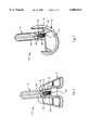
- FIG. 1is an exploded perspective view of a femoral component of an implantable knee joint prosthesis, including a modular medullary stem and a retaining screw, according to the present invention.
- FIG. 2is a sectional view of the femoral component of FIG. 1, taken along section plane 2--2 of FIG. 1 and viewed in the direction of the arrows.
- FIG. 3is a sectional view of the femoral component of FIG. 1, taken along section plane 3--3 of FIG. 1 and viewed in the direction of the arrows.
- FIG. 4is an enlarged portion of the sectional view of FIG. 2, particularly showing the retaining screw in relation to the femoral component and modular stem.
- FIG. 5is an end view of the head of the retaining screw of FIG. 4.
- Femoral component 10of an implantable orthopedic knee joint prosthesis.
- Femoral component 10includes a femoral element 12, a proximal medullary stem 14, and a retaining screw 16.
- Femoral element 12is configured as a posterior stabilized, constrained condylar femoral prosthesis for use with a tibial component having a relatively high central spur that fits closely in the medial-lateral direction between the condyles of the femoral prosthesis.
- the configuration shownis merely illustrative, and other femoral prosthesis configurations can be employed with the present invention.
- Femoral element 12includes condyles 18 and 20, having respective articulating surfaces 22 and 24.
- Condyles 18 and 20are separated at the posterior and inferior aspects of femoral element 12, but are joined at the anterior aspect to form a patellar articulating surface 26.
- the intercondylar opening between condyles 18 and 20is covered by a box 28 defined by side walls 30 and 32 rising from the inward edges of condyles 18 and 20, respectively, and a top wall 34.
- a posterior wall 36completes box 28 and terminates in a cam follower 38 that engages the spur of the tibial component (not shown) to provide posterior stabilization.
- Extending superiorly from top wall 34 of box 28is a boss 40 having a passage 42 therethrough for receiving a shank 44 of screw 16 from below, and for receiving a male taper 46 of proximal stem 14 from above.
- femoral component 10is shown assembled, in cross-section.
- Male conical taper surface 46 of proximal stem 14is received in conical taper locking engagement with female conical taper surface 48 of boss 40.
- Threaded shank 44 of screw 16is threadedly received in a correspondingly threaded blind bore 50 of stem 14.
- a shoulder-stepped bore 52 in boss 40receives screw 16, and includes a superior portion 54 sized for free passage of shank 44 therethrough, and an inferior portion 56 sized larger than portion 54 to form an annular shoulder against which the head 58 of screw 16 bears.
- head 58bears against the shoulder of bore 52 to draw male conical taper 46 of stem 14 into taper locked engagement with female conical taper 48.
- FIGS. 4 and 5an enlarged cross-section of screw 16 and adjacent structures of stem 14 and femoral element 12 is shown, illustrating the anti-backout feature of the present invention.
- Bore 52including superior portion 54 and inferior portion 56, discussed above, are shown clearly, as is the aforementioned annular shoulder, indicated by reference numeral 60.
- Bore 52also includes an annular groove 62 therein having a maximum diameter slightly greater than that of portion 56 of bore 52.
- Annular groove 62in cooperation with a portion of the head 58 of screw 16, described further below, provides the anti-backout feature of the present invention.
- head 58 of screw 16includes a female axial recess 64 that is hexagonal in cross-section.
- Recess 64is convenient for receiving a hexagonal driving tool for imparting torque to screw 16.
- Other polygonal cross-sectionscould be substituted for the hexagonal cross-section of recess 64, as desired.
- Head 58includes a generally annular end-face 66 surrounding recess 64.
- a plurality of splines 68extend generally axially from end-face 66, and are disposed circumferentially about end-face 66.
- Each of splines 68is defined in part by an inner wall 70 lying on a common circle centered on the axis of screw 16 and having a diameter d that is less than the diameter of head 58.
- Each spline 68is further defined by a pair of side walls 72 and 74, each of which lies parallel to, but offset from, a radius of screw 16. Consequently, side walls 72 and 74 of any particular spline 68 converge in a radially inward direction, whereas splines 72 and 74, respectively, of adjacent splines 68 are parallel. As preferred, an even number of splines is provided, equally spaced circumferentially, such that diametrically aligned spaces 76 are defined between adjacent splines.
- Each spline 68is further defined by an outer wall 78 lying on a common circle centered on the axis of screw 16 and having a diameter D that is greater than the diameter of head 58.
- An interrupted frusto-conical surface 80provides a ramped transition between head 58 and outer wall 78.
- the splines 68 of screw 16imparting a castellated appearance to the axial end of head 58, are integral with head 58 and cantilevered therefrom.
- Each spline 68is capable of slight elastic deflection in the radially inward direction.
- the frusto-conical surface 80 of each spline 68is drawn into engagement with the opening of bore 52.
- each spline 68is deflected radially inwardly until outer wall 78 is disposed at the same radial location as bore 52, whereupon outer wall 78 engages bore 52 in spring tension as screw 16 advances.
Landscapes
- Health & Medical Sciences (AREA)
- Orthopedic Medicine & Surgery (AREA)
- Physical Education & Sports Medicine (AREA)
- Cardiology (AREA)
- Oral & Maxillofacial Surgery (AREA)
- Transplantation (AREA)
- Engineering & Computer Science (AREA)
- Biomedical Technology (AREA)
- Heart & Thoracic Surgery (AREA)
- Vascular Medicine (AREA)
- Life Sciences & Earth Sciences (AREA)
- Animal Behavior & Ethology (AREA)
- General Health & Medical Sciences (AREA)
- Public Health (AREA)
- Veterinary Medicine (AREA)
- Prostheses (AREA)
Abstract
Description
Claims (3)
Priority Applications (2)
| Application Number | Priority Date | Filing Date | Title |
|---|---|---|---|
| US09/012,500US6086614A (en) | 1998-01-23 | 1998-01-23 | Orthopedic prosthesis having anti-backout screw |
| PCT/US1999/001359WO1999037253A1 (en) | 1998-01-23 | 1999-01-22 | Orthopedic prosthesis having anti-backout screw |
Applications Claiming Priority (1)
| Application Number | Priority Date | Filing Date | Title |
|---|---|---|---|
| US09/012,500US6086614A (en) | 1998-01-23 | 1998-01-23 | Orthopedic prosthesis having anti-backout screw |
Publications (1)
| Publication Number | Publication Date |
|---|---|
| US6086614Atrue US6086614A (en) | 2000-07-11 |
Family
ID=21755250
Family Applications (1)
| Application Number | Title | Priority Date | Filing Date |
|---|---|---|---|
| US09/012,500Expired - LifetimeUS6086614A (en) | 1998-01-23 | 1998-01-23 | Orthopedic prosthesis having anti-backout screw |
Country Status (2)
| Country | Link |
|---|---|
| US (1) | US6086614A (en) |
| WO (1) | WO1999037253A1 (en) |
Cited By (71)
| Publication number | Priority date | Publication date | Assignee | Title |
|---|---|---|---|---|
| US6524071B2 (en)* | 2000-09-11 | 2003-02-25 | Litex Industries, Inc. | Fan fastener retention structure |
| US20030204268A1 (en)* | 2002-04-25 | 2003-10-30 | Medicinelodge, Inc. | Binary attachment mechanism and method for a modular prosthesis |
| US20030216813A1 (en)* | 2002-03-29 | 2003-11-20 | Ball Robert J. | Distal component for wrist prosthesis |
| US20040117024A1 (en)* | 2002-12-13 | 2004-06-17 | Gerbec Daniel E. | Modular implant for joint reconstruction and method of use |
| US20040230315A1 (en)* | 2000-05-01 | 2004-11-18 | Ek Steven W. | Articular surface implant |
| US6866683B2 (en) | 2002-12-13 | 2005-03-15 | Medicine Lodge, Inc. | Modular implant for joint reconstruction and method of use |
| US6875239B2 (en) | 2002-04-25 | 2005-04-05 | Medicinelodge, Inc. | Modular prosthesis for replacing bone and method |
| US6902583B2 (en) | 2002-04-25 | 2005-06-07 | Medicinelodge, Inc. | Tripartite attachment mechanism and method for a modular prosthesis |
| US20060149235A1 (en)* | 2004-12-20 | 2006-07-06 | Jackson Roger P | Medical implant fastener with nested set screw and method |
| WO2007023196A1 (en) | 2005-07-06 | 2007-03-01 | German Perez Cosias | Whole knee prosthesis |
| US7445639B2 (en) | 2001-02-23 | 2008-11-04 | Biomet Manufacturing Corp. | Knee joint prosthesis |
| US20080306603A1 (en)* | 2007-06-11 | 2008-12-11 | Aesculap Ag | Modular implant part and knee joint prosthesis |
| US7497874B1 (en) | 2001-02-23 | 2009-03-03 | Biomet Manufacturing Corp. | Knee joint prosthesis |
| US20090112177A1 (en)* | 2007-10-31 | 2009-04-30 | Warsaw Orthopedic, Inc. | Implantable Device And Method for Delivering Drug Depots To A Site Beneath the Skin |
| US20090326580A1 (en)* | 2008-06-25 | 2009-12-31 | Anderson Mark E | Spinal fixation device |
| US20100070048A1 (en)* | 2000-05-01 | 2010-03-18 | Arthrosurface, Inc. | System and Method for Joint Resurface Repair |
| US7857858B2 (en) | 2002-04-25 | 2010-12-28 | Zimmer Technology, Inc. | Modular bone implant, tool, and method |
| US20110071641A1 (en)* | 2004-11-22 | 2011-03-24 | Arthrosurface Incorporated | Articular Surface Implant and Delivery System |
| US20110071642A1 (en)* | 2008-03-07 | 2011-03-24 | Aesculap Ag | Medical implant and knee joint endoprosthesis |
| US20110152870A1 (en)* | 2002-12-03 | 2011-06-23 | Arthrosurface Incorporated | Retrograde Delivery of Resurfacing Devices |
| US8157869B2 (en) | 2007-01-10 | 2012-04-17 | Biomet Manufacturing Corp. | Knee joint prosthesis system and method for implantation |
| US8163028B2 (en) | 2007-01-10 | 2012-04-24 | Biomet Manufacturing Corp. | Knee joint prosthesis system and method for implantation |
| US8177841B2 (en) | 2000-05-01 | 2012-05-15 | Arthrosurface Inc. | System and method for joint resurface repair |
| US8187280B2 (en) | 2007-10-10 | 2012-05-29 | Biomet Manufacturing Corp. | Knee joint prosthesis system and method for implantation |
| US8328873B2 (en) | 2007-01-10 | 2012-12-11 | Biomet Manufacturing Corp. | Knee joint prosthesis system and method for implantation |
| US8361159B2 (en) | 2002-12-03 | 2013-01-29 | Arthrosurface, Inc. | System for articular surface replacement |
| US8388624B2 (en) | 2003-02-24 | 2013-03-05 | Arthrosurface Incorporated | Trochlear resurfacing system and method |
| US8523872B2 (en) | 2002-12-03 | 2013-09-03 | Arthrosurface Incorporated | Tibial resurfacing system |
| US8540717B2 (en) | 2000-05-01 | 2013-09-24 | Arthrosurface Incorporated | System and method for joint resurface repair |
| US8556902B2 (en) | 2002-12-03 | 2013-10-15 | Arthrosurface Incorporated | System and method for retrograde procedure |
| US8562616B2 (en) | 2007-10-10 | 2013-10-22 | Biomet Manufacturing, Llc | Knee joint prosthesis system and method for implantation |
| JP2014180557A (en)* | 2013-03-15 | 2014-09-29 | Depuy (Ireland) | Prosthetic components with secondary retention |
| US8926615B2 (en) | 2002-12-03 | 2015-01-06 | Arthrosurface, Inc. | System and method for retrograde procedure |
| US20150025646A1 (en)* | 2013-07-16 | 2015-01-22 | Howmedica Osteonics Corp. | Femoral component with curved central box |
| US9055955B2 (en) | 2000-05-01 | 2015-06-16 | Arthrosurface Inc. | Bone resurfacing system and method |
| US9066716B2 (en) | 2011-03-30 | 2015-06-30 | Arthrosurface Incorporated | Suture coil and suture sheath for tissue repair |
| US9192419B2 (en) | 2008-11-07 | 2015-11-24 | DePuy Synthes Products, Inc. | Zero-profile interbody spacer and coupled plate assembly |
| US9220604B2 (en) | 2010-12-21 | 2015-12-29 | DePuy Synthes Products, Inc. | Intervertebral implants, systems, and methods of use |
| US9220548B2 (en) | 2003-09-03 | 2015-12-29 | DePuy Synthes Products, Inc. | Bone plate with captive clips |
| US9241809B2 (en) | 2010-12-21 | 2016-01-26 | DePuy Synthes Products, Inc. | Intervertebral implants, systems, and methods of use |
| US9283076B2 (en) | 2009-04-17 | 2016-03-15 | Arthrosurface Incorporated | Glenoid resurfacing system and method |
| US9357989B2 (en) | 2000-05-01 | 2016-06-07 | Arthrosurface Incorporated | System and method for joint resurface repair |
| US9358029B2 (en) | 2006-12-11 | 2016-06-07 | Arthrosurface Incorporated | Retrograde resection apparatus and method |
| US9408646B2 (en) | 2003-09-03 | 2016-08-09 | DePuy Synthes Products, Inc. | Bone plate with captive clips |
| US9414870B2 (en) | 2003-09-03 | 2016-08-16 | DePuy Synthes Products, Inc. | Translatable carriage fixation system |
| US9463097B2 (en) | 2003-02-06 | 2016-10-11 | DePuy Synthes Products, Inc. | Intervertebral implant |
| US9468448B2 (en) | 2012-07-03 | 2016-10-18 | Arthrosurface Incorporated | System and method for joint resurfacing and repair |
| US9492200B2 (en) | 2013-04-16 | 2016-11-15 | Arthrosurface Incorporated | Suture system and method |
| US9572681B2 (en) | 2002-02-19 | 2017-02-21 | DePuy Synthes Products, Inc. | Intervertebral implant |
| US9662126B2 (en) | 2009-04-17 | 2017-05-30 | Arthrosurface Incorporated | Glenoid resurfacing system and method |
| US9744049B2 (en) | 2007-11-16 | 2017-08-29 | DePuy Synthes Products, Inc. | Low profile intervertebral implant |
| US9861492B2 (en) | 2014-03-07 | 2018-01-09 | Arthrosurface Incorporated | Anchor for an implant assembly |
| US9867718B2 (en) | 2014-10-22 | 2018-01-16 | DePuy Synthes Products, Inc. | Intervertebral implants, systems, and methods of use |
| US10307198B2 (en) | 2013-03-15 | 2019-06-04 | Depuy Ireland Unlimited Company | Instruments and method for use in disassembling implants |
| US10384048B2 (en) | 2014-07-25 | 2019-08-20 | Warsaw Orthopedic, Inc. | Drug delivery device and methods having an occluding member |
| US10434261B2 (en) | 2016-11-08 | 2019-10-08 | Warsaw Orthopedic, Inc. | Drug pellet delivery system and method |
| US10478603B2 (en) | 2014-07-25 | 2019-11-19 | Warsaw Orthopedic, Inc. | Drug delivery device and methods having a retaining member |
| US10512548B2 (en) | 2006-02-27 | 2019-12-24 | DePuy Synthes Products, Inc. | Intervertebral implant with fixation geometry |
| US10549081B2 (en) | 2016-06-23 | 2020-02-04 | Warsaw Orthopedic, Inc. | Drug delivery device and methods having a retaining member |
| US10624748B2 (en) | 2014-03-07 | 2020-04-21 | Arthrosurface Incorporated | System and method for repairing articular surfaces |
| US10624752B2 (en) | 2006-07-17 | 2020-04-21 | Arthrosurface Incorporated | Tibial resurfacing system and method |
| US10945743B2 (en) | 2009-04-17 | 2021-03-16 | Arthrosurface Incorporated | Glenoid repair system and methods of use thereof |
| US11160663B2 (en) | 2017-08-04 | 2021-11-02 | Arthrosurface Incorporated | Multicomponent articular surface implant |
| US20210393394A1 (en)* | 2020-06-23 | 2021-12-23 | Thomas Zink | Multiple drive interference screw system and device |
| US11298244B2 (en) | 2019-01-31 | 2022-04-12 | K2M, Inc. | Interbody implants and instrumentation |
| US11478358B2 (en) | 2019-03-12 | 2022-10-25 | Arthrosurface Incorporated | Humeral and glenoid articular surface implant systems and methods |
| US11534307B2 (en) | 2019-09-16 | 2022-12-27 | K2M, Inc. | 3D printed cervical standalone implant |
| US11607319B2 (en) | 2014-03-07 | 2023-03-21 | Arthrosurface Incorporated | System and method for repairing articular surfaces |
| US11712276B2 (en) | 2011-12-22 | 2023-08-01 | Arthrosurface Incorporated | System and method for bone fixation |
| US11759614B2 (en) | 2015-11-23 | 2023-09-19 | Warsaw Orthopedic, Inc. | Enhanced stylet for drug depot injector |
| US12251139B2 (en) | 2007-05-23 | 2025-03-18 | Roger P. Jackson | Pivotal bone anchor screw with nested two-piece closure and independent locking twist-in-place insert |
Families Citing this family (1)
| Publication number | Priority date | Publication date | Assignee | Title |
|---|---|---|---|---|
| US9101479B2 (en) | 2013-03-15 | 2015-08-11 | Depuy (Ireland) | Prosthetic components and methods for joint line access |
Citations (5)
| Publication number | Priority date | Publication date | Assignee | Title |
|---|---|---|---|---|
| US4640271A (en)* | 1985-11-07 | 1987-02-03 | Zimmer, Inc. | Bone screw |
| US4672979A (en)* | 1986-01-30 | 1987-06-16 | Cordis Corporation | Suture sleeve assembly |
| US5683472A (en)* | 1995-12-29 | 1997-11-04 | Johnson & Johnson Professional, Inc. | Femoral stem attachment for a modular knee prosthesis |
| US5766255A (en)* | 1996-12-23 | 1998-06-16 | Johnson & Johnson Professional, Inc. | Modular joint prosthesis stabilization and augmentation system |
| US5879389A (en)* | 1995-04-07 | 1999-03-09 | Koshino; Tomihisa | Medical substituting element for hard tissues and artificial joint |
Family Cites Families (3)
| Publication number | Priority date | Publication date | Assignee | Title |
|---|---|---|---|---|
| ES2085604T3 (en)* | 1991-03-07 | 1996-06-01 | Sulzer Medizinaltechnik Ag | NUT FOR THREADED UNION FOR IMPLANTS. |
| US5397360A (en)* | 1993-02-11 | 1995-03-14 | Osteonics Corp. | Modular components for prosthetic implants |
| FR2712047B1 (en)* | 1993-11-05 | 1995-12-08 | Jeanson Jean Francois | Self-retention device for assembly and fixing elements such as screws, bolts and nuts. |
- 1998
- 1998-01-23USUS09/012,500patent/US6086614A/ennot_activeExpired - Lifetime
- 1999
- 1999-01-22WOPCT/US1999/001359patent/WO1999037253A1/enactiveApplication Filing
Patent Citations (5)
| Publication number | Priority date | Publication date | Assignee | Title |
|---|---|---|---|---|
| US4640271A (en)* | 1985-11-07 | 1987-02-03 | Zimmer, Inc. | Bone screw |
| US4672979A (en)* | 1986-01-30 | 1987-06-16 | Cordis Corporation | Suture sleeve assembly |
| US5879389A (en)* | 1995-04-07 | 1999-03-09 | Koshino; Tomihisa | Medical substituting element for hard tissues and artificial joint |
| US5683472A (en)* | 1995-12-29 | 1997-11-04 | Johnson & Johnson Professional, Inc. | Femoral stem attachment for a modular knee prosthesis |
| US5766255A (en)* | 1996-12-23 | 1998-06-16 | Johnson & Johnson Professional, Inc. | Modular joint prosthesis stabilization and augmentation system |
Cited By (144)
| Publication number | Priority date | Publication date | Assignee | Title |
|---|---|---|---|---|
| US20100070048A1 (en)* | 2000-05-01 | 2010-03-18 | Arthrosurface, Inc. | System and Method for Joint Resurface Repair |
| US8864827B2 (en) | 2000-05-01 | 2014-10-21 | Arthrosurface Inc. | System and method for joint resurface repair |
| US8540717B2 (en) | 2000-05-01 | 2013-09-24 | Arthrosurface Incorporated | System and method for joint resurface repair |
| US9055955B2 (en) | 2000-05-01 | 2015-06-16 | Arthrosurface Inc. | Bone resurfacing system and method |
| US20040230315A1 (en)* | 2000-05-01 | 2004-11-18 | Ek Steven W. | Articular surface implant |
| US9204873B2 (en) | 2000-05-01 | 2015-12-08 | Arthrosurface Incorporated | System and method for joint resurface repair |
| US8177841B2 (en) | 2000-05-01 | 2012-05-15 | Arthrosurface Inc. | System and method for joint resurface repair |
| US9357989B2 (en) | 2000-05-01 | 2016-06-07 | Arthrosurface Incorporated | System and method for joint resurface repair |
| US8147559B2 (en)* | 2000-05-01 | 2012-04-03 | Arthrosurface Incorporated | System and method for joint resurface repair |
| US6524071B2 (en)* | 2000-09-11 | 2003-02-25 | Litex Industries, Inc. | Fan fastener retention structure |
| US7445639B2 (en) | 2001-02-23 | 2008-11-04 | Biomet Manufacturing Corp. | Knee joint prosthesis |
| US7497874B1 (en) | 2001-02-23 | 2009-03-03 | Biomet Manufacturing Corp. | Knee joint prosthesis |
| US9572681B2 (en) | 2002-02-19 | 2017-02-21 | DePuy Synthes Products, Inc. | Intervertebral implant |
| US10492922B2 (en) | 2002-02-19 | 2019-12-03 | DePuy Synthes Products, Inc. | Intervertebral implant |
| US20030216813A1 (en)* | 2002-03-29 | 2003-11-20 | Ball Robert J. | Distal component for wrist prosthesis |
| US6890358B2 (en) | 2002-03-29 | 2005-05-10 | Depuy Products, Inc. | Distal component for wrist prosthesis |
| US20030204268A1 (en)* | 2002-04-25 | 2003-10-30 | Medicinelodge, Inc. | Binary attachment mechanism and method for a modular prosthesis |
| US8241367B2 (en) | 2002-04-25 | 2012-08-14 | Zimmer, Inc. | Modular bone implant, tool, and method |
| US6875239B2 (en) | 2002-04-25 | 2005-04-05 | Medicinelodge, Inc. | Modular prosthesis for replacing bone and method |
| US6902583B2 (en) | 2002-04-25 | 2005-06-07 | Medicinelodge, Inc. | Tripartite attachment mechanism and method for a modular prosthesis |
| US7857858B2 (en) | 2002-04-25 | 2010-12-28 | Zimmer Technology, Inc. | Modular bone implant, tool, and method |
| US8361159B2 (en) | 2002-12-03 | 2013-01-29 | Arthrosurface, Inc. | System for articular surface replacement |
| US9044343B2 (en) | 2002-12-03 | 2015-06-02 | Arthrosurface Incorporated | System for articular surface replacement |
| US10076343B2 (en) | 2002-12-03 | 2018-09-18 | Arthrosurface Incorporated | System for articular surface replacement |
| US8663230B2 (en) | 2002-12-03 | 2014-03-04 | Arthrosurface Incorporated | Retrograde delivery of resurfacing devices |
| US8556902B2 (en) | 2002-12-03 | 2013-10-15 | Arthrosurface Incorporated | System and method for retrograde procedure |
| US20110152870A1 (en)* | 2002-12-03 | 2011-06-23 | Arthrosurface Incorporated | Retrograde Delivery of Resurfacing Devices |
| US8926615B2 (en) | 2002-12-03 | 2015-01-06 | Arthrosurface, Inc. | System and method for retrograde procedure |
| US8523872B2 (en) | 2002-12-03 | 2013-09-03 | Arthrosurface Incorporated | Tibial resurfacing system |
| US6887276B2 (en) | 2002-12-13 | 2005-05-03 | Medicine Lodge, Inc | Modular implant for joint reconstruction and method of use |
| US6866683B2 (en) | 2002-12-13 | 2005-03-15 | Medicine Lodge, Inc. | Modular implant for joint reconstruction and method of use |
| US20040117024A1 (en)* | 2002-12-13 | 2004-06-17 | Gerbec Daniel E. | Modular implant for joint reconstruction and method of use |
| US10064740B2 (en) | 2003-02-06 | 2018-09-04 | DePuy Synthes Products, LLC | Intervertebral implant |
| US10660765B2 (en) | 2003-02-06 | 2020-05-26 | DePuy Synthes Products, Inc. | Intervertebral implant |
| US9463097B2 (en) | 2003-02-06 | 2016-10-11 | DePuy Synthes Products, Inc. | Intervertebral implant |
| US9931211B2 (en) | 2003-02-24 | 2018-04-03 | Arthrosurface Incorporated | Trochlear resurfacing system and method |
| US8388624B2 (en) | 2003-02-24 | 2013-03-05 | Arthrosurface Incorporated | Trochlear resurfacing system and method |
| US10624749B2 (en) | 2003-02-24 | 2020-04-21 | Arthrosurface Incorporated | Trochlear resurfacing system and method |
| US9351745B2 (en) | 2003-02-24 | 2016-05-31 | Arthrosurface Incorporated | Trochlear resurfacing system and method |
| US11337819B2 (en) | 2003-02-24 | 2022-05-24 | Arthrosurface Incorporated | Trochlear resurfacing system and method |
| US9414870B2 (en) | 2003-09-03 | 2016-08-16 | DePuy Synthes Products, Inc. | Translatable carriage fixation system |
| US9220548B2 (en) | 2003-09-03 | 2015-12-29 | DePuy Synthes Products, Inc. | Bone plate with captive clips |
| US9408646B2 (en) | 2003-09-03 | 2016-08-09 | DePuy Synthes Products, Inc. | Bone plate with captive clips |
| US10368927B2 (en) | 2003-09-03 | 2019-08-06 | DePuy Synthes Products, Inc. | Bone plate with captive clips |
| US20110071641A1 (en)* | 2004-11-22 | 2011-03-24 | Arthrosurface Incorporated | Articular Surface Implant and Delivery System |
| US8961614B2 (en) | 2004-11-22 | 2015-02-24 | Arthrosurface, Inc. | Articular surface implant and delivery system |
| US20060149235A1 (en)* | 2004-12-20 | 2006-07-06 | Jackson Roger P | Medical implant fastener with nested set screw and method |
| US7204838B2 (en)* | 2004-12-20 | 2007-04-17 | Jackson Roger P | Medical implant fastener with nested set screw and method |
| WO2007023196A1 (en) | 2005-07-06 | 2007-03-01 | German Perez Cosias | Whole knee prosthesis |
| US11696837B2 (en) | 2006-02-27 | 2023-07-11 | DePuy Synthes Products, Inc. | Intervertebral implant with fixation geometry |
| US10512548B2 (en) | 2006-02-27 | 2019-12-24 | DePuy Synthes Products, Inc. | Intervertebral implant with fixation geometry |
| US11471289B2 (en) | 2006-07-17 | 2022-10-18 | Arthrosurface Incorporated | Tibial resurfacing system and method |
| US10624752B2 (en) | 2006-07-17 | 2020-04-21 | Arthrosurface Incorporated | Tibial resurfacing system and method |
| US10959740B2 (en) | 2006-12-11 | 2021-03-30 | Arthrosurface Incorporated | Retrograde resection apparatus and method |
| US10045788B2 (en) | 2006-12-11 | 2018-08-14 | Arthrosurface Incorporated | Retrograde resection apparatus and method |
| US9358029B2 (en) | 2006-12-11 | 2016-06-07 | Arthrosurface Incorporated | Retrograde resection apparatus and method |
| US8328873B2 (en) | 2007-01-10 | 2012-12-11 | Biomet Manufacturing Corp. | Knee joint prosthesis system and method for implantation |
| US8157869B2 (en) | 2007-01-10 | 2012-04-17 | Biomet Manufacturing Corp. | Knee joint prosthesis system and method for implantation |
| US8163028B2 (en) | 2007-01-10 | 2012-04-24 | Biomet Manufacturing Corp. | Knee joint prosthesis system and method for implantation |
| US8936648B2 (en) | 2007-01-10 | 2015-01-20 | Biomet Manufacturing, Llc | Knee joint prosthesis system and method for implantation |
| US8480751B2 (en) | 2007-01-10 | 2013-07-09 | Biomet Manufacturing, Llc | Knee joint prosthesis system and method for implantation |
| US12251139B2 (en) | 2007-05-23 | 2025-03-18 | Roger P. Jackson | Pivotal bone anchor screw with nested two-piece closure and independent locking twist-in-place insert |
| US8540775B2 (en) | 2007-06-11 | 2013-09-24 | Aesculap Ag | Modular implant part and knee joint prosthesis |
| US20080306603A1 (en)* | 2007-06-11 | 2008-12-11 | Aesculap Ag | Modular implant part and knee joint prosthesis |
| US9763793B2 (en) | 2007-10-10 | 2017-09-19 | Biomet Manufacturing, Llc | Knee joint prosthesis system and method for implantation |
| US8187280B2 (en) | 2007-10-10 | 2012-05-29 | Biomet Manufacturing Corp. | Knee joint prosthesis system and method for implantation |
| US8562616B2 (en) | 2007-10-10 | 2013-10-22 | Biomet Manufacturing, Llc | Knee joint prosthesis system and method for implantation |
| US10736747B2 (en) | 2007-10-10 | 2020-08-11 | Biomet Manufacturing, Llc | Knee joint prosthesis system and method for implantation |
| US20090112177A1 (en)* | 2007-10-31 | 2009-04-30 | Warsaw Orthopedic, Inc. | Implantable Device And Method for Delivering Drug Depots To A Site Beneath the Skin |
| US8029478B2 (en) | 2007-10-31 | 2011-10-04 | Warsaw Orthopedic, Inc. | Implantable device and method for delivering drug depots to a site beneath the skin |
| US9744049B2 (en) | 2007-11-16 | 2017-08-29 | DePuy Synthes Products, Inc. | Low profile intervertebral implant |
| US10137003B2 (en) | 2007-11-16 | 2018-11-27 | DePuy Synthes Products, Inc. | Low profile intervertebral implant |
| US10543102B2 (en) | 2007-11-16 | 2020-01-28 | DePuy Synthes Products, Inc. | Low profile intervertebral implant |
| US9649204B2 (en) | 2008-03-07 | 2017-05-16 | Aesculap Ag | Medical implant and knee joint endoprosthesis |
| US20110071642A1 (en)* | 2008-03-07 | 2011-03-24 | Aesculap Ag | Medical implant and knee joint endoprosthesis |
| US9044328B2 (en) | 2008-03-07 | 2015-06-02 | Aesculap Ag | Medical implant and knee joint endoprosthesis |
| US8425514B2 (en) | 2008-06-25 | 2013-04-23 | Westmark Medical, Llc. | Spinal fixation device |
| US20090326580A1 (en)* | 2008-06-25 | 2009-12-31 | Anderson Mark E | Spinal fixation device |
| US12263096B2 (en) | 2008-11-07 | 2025-04-01 | DePuy Synthes Products, Inc. | Zero-profile interbody spacer and coupled plate assembly |
| US10531960B2 (en) | 2008-11-07 | 2020-01-14 | DePuy Synthes Products, Inc. | Zero-profile interbody spacer and coupled plate assembly |
| US11612492B2 (en) | 2008-11-07 | 2023-03-28 | DePuy Synthes Products, Inc. | Zero-profile interbody spacer and coupled plate assembly |
| US9402735B2 (en) | 2008-11-07 | 2016-08-02 | DePuy Synthes Products, Inc. | Zero-profile interbody spacer and coupled plate assembly |
| US11517444B2 (en) | 2008-11-07 | 2022-12-06 | DePuy Synthes Products, Inc. | Zero-profile interbody spacer and coupled plate assembly |
| US9414935B2 (en) | 2008-11-07 | 2016-08-16 | DePuy Synthes Products, Inc. | Zero-profile interbody spacer and coupled plate assembly |
| US9192419B2 (en) | 2008-11-07 | 2015-11-24 | DePuy Synthes Products, Inc. | Zero-profile interbody spacer and coupled plate assembly |
| US10433976B2 (en) | 2008-11-07 | 2019-10-08 | DePuy Synthes Products, Inc. | Zero-profile interbody spacer and coupled plate assembly |
| US10945743B2 (en) | 2009-04-17 | 2021-03-16 | Arthrosurface Incorporated | Glenoid repair system and methods of use thereof |
| US10478200B2 (en) | 2009-04-17 | 2019-11-19 | Arthrosurface Incorporated | Glenoid resurfacing system and method |
| US9662126B2 (en) | 2009-04-17 | 2017-05-30 | Arthrosurface Incorporated | Glenoid resurfacing system and method |
| US9283076B2 (en) | 2009-04-17 | 2016-03-15 | Arthrosurface Incorporated | Glenoid resurfacing system and method |
| US11478259B2 (en) | 2009-04-17 | 2022-10-25 | Arthrosurface, Incorporated | Glenoid resurfacing system and method |
| US9220604B2 (en) | 2010-12-21 | 2015-12-29 | DePuy Synthes Products, Inc. | Intervertebral implants, systems, and methods of use |
| US10507117B2 (en) | 2010-12-21 | 2019-12-17 | DePuy Synthes Products, Inc. | Intervertebral implants, systems, and methods of use |
| US9848992B2 (en) | 2010-12-21 | 2017-12-26 | DePuy Synthes Products, Inc. | Intervertebral implants, systems, and methods of use |
| US9241809B2 (en) | 2010-12-21 | 2016-01-26 | DePuy Synthes Products, Inc. | Intervertebral implants, systems, and methods of use |
| US11458027B2 (en) | 2010-12-21 | 2022-10-04 | DePuy Synthes Products, Inc. | Intervertebral implants, systems, and methods of use |
| US9066716B2 (en) | 2011-03-30 | 2015-06-30 | Arthrosurface Incorporated | Suture coil and suture sheath for tissue repair |
| US11712276B2 (en) | 2011-12-22 | 2023-08-01 | Arthrosurface Incorporated | System and method for bone fixation |
| US10307172B2 (en) | 2012-07-03 | 2019-06-04 | Arthrosurface Incorporated | System and method for joint resurfacing and repair |
| US9468448B2 (en) | 2012-07-03 | 2016-10-18 | Arthrosurface Incorporated | System and method for joint resurfacing and repair |
| US11191552B2 (en) | 2012-07-03 | 2021-12-07 | Arthrosurface, Incorporated | System and method for joint resurfacing and repair |
| JP2014180557A (en)* | 2013-03-15 | 2014-09-29 | Depuy (Ireland) | Prosthetic components with secondary retention |
| US11357562B2 (en) | 2013-03-15 | 2022-06-14 | Depuy Ireland Unlimited Company | Instruments and method for use in disassembling implants |
| US10307198B2 (en) | 2013-03-15 | 2019-06-04 | Depuy Ireland Unlimited Company | Instruments and method for use in disassembling implants |
| US11648036B2 (en) | 2013-04-16 | 2023-05-16 | Arthrosurface Incorporated | Suture system and method |
| US10695096B2 (en) | 2013-04-16 | 2020-06-30 | Arthrosurface Incorporated | Suture system and method |
| US9492200B2 (en) | 2013-04-16 | 2016-11-15 | Arthrosurface Incorporated | Suture system and method |
| US20150025646A1 (en)* | 2013-07-16 | 2015-01-22 | Howmedica Osteonics Corp. | Femoral component with curved central box |
| US10624748B2 (en) | 2014-03-07 | 2020-04-21 | Arthrosurface Incorporated | System and method for repairing articular surfaces |
| US9861492B2 (en) | 2014-03-07 | 2018-01-09 | Arthrosurface Incorporated | Anchor for an implant assembly |
| US11083587B2 (en) | 2014-03-07 | 2021-08-10 | Arthrosurface Incorporated | Implant and anchor assembly |
| US11766334B2 (en) | 2014-03-07 | 2023-09-26 | Arthrosurface Incorporated | System and method for repairing articular surfaces |
| US11607319B2 (en) | 2014-03-07 | 2023-03-21 | Arthrosurface Incorporated | System and method for repairing articular surfaces |
| US9962265B2 (en) | 2014-03-07 | 2018-05-08 | Arthrosurface Incorporated | System and method for repairing articular surfaces |
| US10624754B2 (en) | 2014-03-07 | 2020-04-21 | Arthrosurface Incorporated | System and method for repairing articular surfaces |
| US9931219B2 (en) | 2014-03-07 | 2018-04-03 | Arthrosurface Incorporated | Implant and anchor assembly |
| US10575957B2 (en) | 2014-03-07 | 2020-03-03 | Arthrosurface Incoporated | Anchor for an implant assembly |
| US11504513B2 (en) | 2014-07-25 | 2022-11-22 | Warsaw Orthopedic, Inc. | Drug delivery device and methods having a retaining member |
| US11464958B2 (en) | 2014-07-25 | 2022-10-11 | Warsaw Orthopedic, Inc. | Drug delivery methods having an occluding member |
| US10478603B2 (en) | 2014-07-25 | 2019-11-19 | Warsaw Orthopedic, Inc. | Drug delivery device and methods having a retaining member |
| US10384048B2 (en) | 2014-07-25 | 2019-08-20 | Warsaw Orthopedic, Inc. | Drug delivery device and methods having an occluding member |
| US11540927B2 (en) | 2014-10-22 | 2023-01-03 | DePuy Synthes Products, Inc. | Intervertebral implants, systems, and methods of use |
| US10702394B2 (en) | 2014-10-22 | 2020-07-07 | DePuy Synthes Products, Inc. | Intervertebral implants, systems, and methods of use |
| US9867718B2 (en) | 2014-10-22 | 2018-01-16 | DePuy Synthes Products, Inc. | Intervertebral implants, systems, and methods of use |
| US10010432B2 (en) | 2014-10-22 | 2018-07-03 | DePuy Synthes Products, Inc. | Intervertebral implants, systems, and methods of use |
| US10130492B2 (en) | 2014-10-22 | 2018-11-20 | DePuy Synthes Products, Inc. | Intervertebral implants, systems, and methods of use |
| US11759614B2 (en) | 2015-11-23 | 2023-09-19 | Warsaw Orthopedic, Inc. | Enhanced stylet for drug depot injector |
| US10549081B2 (en) | 2016-06-23 | 2020-02-04 | Warsaw Orthopedic, Inc. | Drug delivery device and methods having a retaining member |
| US12076519B2 (en) | 2016-06-23 | 2024-09-03 | Warsaw Orthopedic, Inc. | Drug delivery device and methods having a retaining member |
| US11413442B2 (en) | 2016-06-23 | 2022-08-16 | Warsaw Orthopedic, Inc. | Drug delivery device and methods having a retaining member |
| US11478587B2 (en) | 2016-11-08 | 2022-10-25 | Warsaw Orthopedic, Inc. | Drug depot delivery system and method |
| US12017050B2 (en) | 2016-11-08 | 2024-06-25 | Warsaw Orthopedic, Inc. | Drug depot delivery system and method |
| US10434261B2 (en) | 2016-11-08 | 2019-10-08 | Warsaw Orthopedic, Inc. | Drug pellet delivery system and method |
| US11160663B2 (en) | 2017-08-04 | 2021-11-02 | Arthrosurface Incorporated | Multicomponent articular surface implant |
| US11298244B2 (en) | 2019-01-31 | 2022-04-12 | K2M, Inc. | Interbody implants and instrumentation |
| US11918487B2 (en) | 2019-01-31 | 2024-03-05 | K2M, Inc. | Interbody implants and instrumentation |
| US11969357B2 (en) | 2019-01-31 | 2024-04-30 | K2M, Inc. | Tritanium AL implants and instrumentation |
| US11617659B2 (en) | 2019-01-31 | 2023-04-04 | K2M, Inc. | Tritanium Al implants and instrumentation |
| US12226320B2 (en) | 2019-01-31 | 2025-02-18 | K2M, Inc. | Tritanium AL implants and instrumentation |
| US12303401B2 (en) | 2019-01-31 | 2025-05-20 | K2M, Inc. | Tritanium AL implants and instrumentation |
| US11478358B2 (en) | 2019-03-12 | 2022-10-25 | Arthrosurface Incorporated | Humeral and glenoid articular surface implant systems and methods |
| US11534307B2 (en) | 2019-09-16 | 2022-12-27 | K2M, Inc. | 3D printed cervical standalone implant |
| US12409045B2 (en) | 2019-09-16 | 2025-09-09 | Vb Spine Us Opco Llc | 3D printed cervical standalone implant |
| US20210393394A1 (en)* | 2020-06-23 | 2021-12-23 | Thomas Zink | Multiple drive interference screw system and device |
Also Published As
| Publication number | Publication date |
|---|---|
| WO1999037253A1 (en) | 1999-07-29 |
Similar Documents
| Publication | Publication Date | Title |
|---|---|---|
| US6086614A (en) | Orthopedic prosthesis having anti-backout screw | |
| US6074424A (en) | Implantable knee joint prosthesis convertible from primary to revision | |
| US7799085B2 (en) | Modular implant system with fully porous coated sleeve | |
| AU2020200583B2 (en) | Knee prosthesis system with standard and distal offset joint line | |
| US8366782B2 (en) | Modular orthopaedic implant system with multi-use stems | |
| US5405398A (en) | Prosthetic knee with posterior stabilized femoral component | |
| US6126693A (en) | Tapped box femoral stem attachment for a modular knee prosthesis | |
| AU750643B2 (en) | Stem offset mechanism for joint prosthesis | |
| EP0714645B1 (en) | Modular knee prosthesis | |
| US8268006B2 (en) | Constrained prosthetic knee with rotating bearing | |
| US5876456A (en) | Implantable prosthesis having interference-locked hole plugs | |
| EP1913902B1 (en) | Bowed femoral sleeve | |
| US20040049285A1 (en) | Duo-fixation prosthetic joints | |
| US6143034A (en) | Implantable hinged knee prosthesis having tibial baseplate | |
| EP1417938A1 (en) | Constrained prosthetic knee with rotating bearning | |
| CA2730564C (en) | Femoral head prosthesis | |
| AU5934599A (en) | Modular stem and sleeve prosthesis | |
| US7998218B1 (en) | Modular orthopedic implant | |
| US8632599B1 (en) | Knee prosthesis system with side-mounted augments | |
| US9144498B2 (en) | Modular knee prosthesis system for use with different load requirements | |
| US20200046508A1 (en) | Knee prosthesis system and method |
Legal Events
| Date | Code | Title | Description |
|---|---|---|---|
| AS | Assignment | Owner name:SULZER ORTHOPEDICS INC., TEXAS Free format text:ASSIGNMENT OF ASSIGNORS INTEREST;ASSIGNOR:MUMME, CHARLES;REEL/FRAME:008965/0228 Effective date:19980120 | |
| STCF | Information on status: patent grant | Free format text:PATENTED CASE | |
| AS | Assignment | Owner name:CENTERPULSE ORTHOPEDICS INC., TEXAS Free format text:CHANGE OF NAME;ASSIGNOR:SULZER ORTHOPEDICS INC.;REEL/FRAME:013516/0549 Effective date:20020930 | |
| FPAY | Fee payment | Year of fee payment:4 | |
| AS | Assignment | Owner name:ZIMMER AUSTIN, INC., TEXAS Free format text:CHANGE OF NAME;ASSIGNOR:CENTERPULSE ORTHOPEDICS INC.;REEL/FRAME:016263/0264 Effective date:20040602 | |
| AS | Assignment | Owner name:CENTERPULSE ORTHOPEDICS INC., TEXAS Free format text:CHANGE OF NAME;ASSIGNOR:SULZER ORTHOPEDICS INC.;REEL/FRAME:016761/0136 Effective date:20020930 | |
| AS | Assignment | Owner name:ZIMMER, INC., INDIANA Free format text:CHANGE OF NAME;ASSIGNOR:ZIMMER AUSTIN, INC.;REEL/FRAME:017435/0714 Effective date:20060208 | |
| FPAY | Fee payment | Year of fee payment:8 | |
| REMI | Maintenance fee reminder mailed | ||
| FPAY | Fee payment | Year of fee payment:12 |