US6086613A - Spacer assembly for use in spinal surgeries - Google Patents
Spacer assembly for use in spinal surgeriesDownload PDFInfo
- Publication number
- US6086613A US6086613AUS09/218,745US21874598AUS6086613AUS 6086613 AUS6086613 AUS 6086613AUS 21874598 AUS21874598 AUS 21874598AUS 6086613 AUS6086613 AUS 6086613A
- Authority
- US
- United States
- Prior art keywords
- spacer
- side wall
- end cap
- extending
- opposite ends
- Prior art date
- Legal status (The legal status is an assumption and is not a legal conclusion. Google has not performed a legal analysis and makes no representation as to the accuracy of the status listed.)
- Expired - Lifetime
Links
Images


Classifications
- A—HUMAN NECESSITIES
- A61—MEDICAL OR VETERINARY SCIENCE; HYGIENE
- A61F—FILTERS IMPLANTABLE INTO BLOOD VESSELS; PROSTHESES; DEVICES PROVIDING PATENCY TO, OR PREVENTING COLLAPSING OF, TUBULAR STRUCTURES OF THE BODY, e.g. STENTS; ORTHOPAEDIC, NURSING OR CONTRACEPTIVE DEVICES; FOMENTATION; TREATMENT OR PROTECTION OF EYES OR EARS; BANDAGES, DRESSINGS OR ABSORBENT PADS; FIRST-AID KITS
- A61F2/00—Filters implantable into blood vessels; Prostheses, i.e. artificial substitutes or replacements for parts of the body; Appliances for connecting them with the body; Devices providing patency to, or preventing collapsing of, tubular structures of the body, e.g. stents
- A61F2/02—Prostheses implantable into the body
- A61F2/30—Joints
- A61F2/44—Joints for the spine, e.g. vertebrae, spinal discs
- A61F2/442—Intervertebral or spinal discs, e.g. resilient
- A—HUMAN NECESSITIES
- A61—MEDICAL OR VETERINARY SCIENCE; HYGIENE
- A61F—FILTERS IMPLANTABLE INTO BLOOD VESSELS; PROSTHESES; DEVICES PROVIDING PATENCY TO, OR PREVENTING COLLAPSING OF, TUBULAR STRUCTURES OF THE BODY, e.g. STENTS; ORTHOPAEDIC, NURSING OR CONTRACEPTIVE DEVICES; FOMENTATION; TREATMENT OR PROTECTION OF EYES OR EARS; BANDAGES, DRESSINGS OR ABSORBENT PADS; FIRST-AID KITS
- A61F2/00—Filters implantable into blood vessels; Prostheses, i.e. artificial substitutes or replacements for parts of the body; Appliances for connecting them with the body; Devices providing patency to, or preventing collapsing of, tubular structures of the body, e.g. stents
- A61F2/02—Prostheses implantable into the body
- A61F2/30—Joints
- A61F2/30721—Accessories
- A61F2/30744—End caps, e.g. for closing an endoprosthetic cavity
- A—HUMAN NECESSITIES
- A61—MEDICAL OR VETERINARY SCIENCE; HYGIENE
- A61F—FILTERS IMPLANTABLE INTO BLOOD VESSELS; PROSTHESES; DEVICES PROVIDING PATENCY TO, OR PREVENTING COLLAPSING OF, TUBULAR STRUCTURES OF THE BODY, e.g. STENTS; ORTHOPAEDIC, NURSING OR CONTRACEPTIVE DEVICES; FOMENTATION; TREATMENT OR PROTECTION OF EYES OR EARS; BANDAGES, DRESSINGS OR ABSORBENT PADS; FIRST-AID KITS
- A61F2/00—Filters implantable into blood vessels; Prostheses, i.e. artificial substitutes or replacements for parts of the body; Appliances for connecting them with the body; Devices providing patency to, or preventing collapsing of, tubular structures of the body, e.g. stents
- A61F2/02—Prostheses implantable into the body
- A61F2/30—Joints
- A61F2/44—Joints for the spine, e.g. vertebrae, spinal discs
- A61F2/4455—Joints for the spine, e.g. vertebrae, spinal discs for the fusion of spinal bodies, e.g. intervertebral fusion of adjacent spinal bodies, e.g. fusion cages
- A61F2/4465—Joints for the spine, e.g. vertebrae, spinal discs for the fusion of spinal bodies, e.g. intervertebral fusion of adjacent spinal bodies, e.g. fusion cages having a circular or kidney shaped cross-section substantially perpendicular to the axis of the spine
- A—HUMAN NECESSITIES
- A61—MEDICAL OR VETERINARY SCIENCE; HYGIENE
- A61F—FILTERS IMPLANTABLE INTO BLOOD VESSELS; PROSTHESES; DEVICES PROVIDING PATENCY TO, OR PREVENTING COLLAPSING OF, TUBULAR STRUCTURES OF THE BODY, e.g. STENTS; ORTHOPAEDIC, NURSING OR CONTRACEPTIVE DEVICES; FOMENTATION; TREATMENT OR PROTECTION OF EYES OR EARS; BANDAGES, DRESSINGS OR ABSORBENT PADS; FIRST-AID KITS
- A61F2/00—Filters implantable into blood vessels; Prostheses, i.e. artificial substitutes or replacements for parts of the body; Appliances for connecting them with the body; Devices providing patency to, or preventing collapsing of, tubular structures of the body, e.g. stents
- A61F2/02—Prostheses implantable into the body
- A61F2/30—Joints
- A61F2/30721—Accessories
- A61F2/30724—Spacers for centering an implant in a bone cavity, e.g. in a cement-receiving cavity
- A—HUMAN NECESSITIES
- A61—MEDICAL OR VETERINARY SCIENCE; HYGIENE
- A61F—FILTERS IMPLANTABLE INTO BLOOD VESSELS; PROSTHESES; DEVICES PROVIDING PATENCY TO, OR PREVENTING COLLAPSING OF, TUBULAR STRUCTURES OF THE BODY, e.g. STENTS; ORTHOPAEDIC, NURSING OR CONTRACEPTIVE DEVICES; FOMENTATION; TREATMENT OR PROTECTION OF EYES OR EARS; BANDAGES, DRESSINGS OR ABSORBENT PADS; FIRST-AID KITS
- A61F2/00—Filters implantable into blood vessels; Prostheses, i.e. artificial substitutes or replacements for parts of the body; Appliances for connecting them with the body; Devices providing patency to, or preventing collapsing of, tubular structures of the body, e.g. stents
- A61F2/02—Prostheses implantable into the body
- A61F2/30—Joints
- A61F2/30767—Special external or bone-contacting surface, e.g. coating for improving bone ingrowth
- A—HUMAN NECESSITIES
- A61—MEDICAL OR VETERINARY SCIENCE; HYGIENE
- A61F—FILTERS IMPLANTABLE INTO BLOOD VESSELS; PROSTHESES; DEVICES PROVIDING PATENCY TO, OR PREVENTING COLLAPSING OF, TUBULAR STRUCTURES OF THE BODY, e.g. STENTS; ORTHOPAEDIC, NURSING OR CONTRACEPTIVE DEVICES; FOMENTATION; TREATMENT OR PROTECTION OF EYES OR EARS; BANDAGES, DRESSINGS OR ABSORBENT PADS; FIRST-AID KITS
- A61F2/00—Filters implantable into blood vessels; Prostheses, i.e. artificial substitutes or replacements for parts of the body; Appliances for connecting them with the body; Devices providing patency to, or preventing collapsing of, tubular structures of the body, e.g. stents
- A61F2/02—Prostheses implantable into the body
- A61F2/30—Joints
- A61F2/46—Special tools for implanting artificial joints
- A61F2/4603—Special tools for implanting artificial joints for insertion or extraction of endoprosthetic joints or of accessories thereof
- A61F2/4611—Special tools for implanting artificial joints for insertion or extraction of endoprosthetic joints or of accessories thereof of spinal prostheses
- A—HUMAN NECESSITIES
- A61—MEDICAL OR VETERINARY SCIENCE; HYGIENE
- A61F—FILTERS IMPLANTABLE INTO BLOOD VESSELS; PROSTHESES; DEVICES PROVIDING PATENCY TO, OR PREVENTING COLLAPSING OF, TUBULAR STRUCTURES OF THE BODY, e.g. STENTS; ORTHOPAEDIC, NURSING OR CONTRACEPTIVE DEVICES; FOMENTATION; TREATMENT OR PROTECTION OF EYES OR EARS; BANDAGES, DRESSINGS OR ABSORBENT PADS; FIRST-AID KITS
- A61F2/00—Filters implantable into blood vessels; Prostheses, i.e. artificial substitutes or replacements for parts of the body; Appliances for connecting them with the body; Devices providing patency to, or preventing collapsing of, tubular structures of the body, e.g. stents
- A61F2/02—Prostheses implantable into the body
- A61F2/30—Joints
- A61F2/46—Special tools for implanting artificial joints
- A61F2/4637—Special tools for implanting artificial joints for connecting or disconnecting two parts of a prosthesis
- A—HUMAN NECESSITIES
- A61—MEDICAL OR VETERINARY SCIENCE; HYGIENE
- A61F—FILTERS IMPLANTABLE INTO BLOOD VESSELS; PROSTHESES; DEVICES PROVIDING PATENCY TO, OR PREVENTING COLLAPSING OF, TUBULAR STRUCTURES OF THE BODY, e.g. STENTS; ORTHOPAEDIC, NURSING OR CONTRACEPTIVE DEVICES; FOMENTATION; TREATMENT OR PROTECTION OF EYES OR EARS; BANDAGES, DRESSINGS OR ABSORBENT PADS; FIRST-AID KITS
- A61F2/00—Filters implantable into blood vessels; Prostheses, i.e. artificial substitutes or replacements for parts of the body; Appliances for connecting them with the body; Devices providing patency to, or preventing collapsing of, tubular structures of the body, e.g. stents
- A61F2/02—Prostheses implantable into the body
- A61F2/28—Bones
- A61F2002/2835—Bone graft implants for filling a bony defect or an endoprosthesis cavity, e.g. by synthetic material or biological material
- A—HUMAN NECESSITIES
- A61—MEDICAL OR VETERINARY SCIENCE; HYGIENE
- A61F—FILTERS IMPLANTABLE INTO BLOOD VESSELS; PROSTHESES; DEVICES PROVIDING PATENCY TO, OR PREVENTING COLLAPSING OF, TUBULAR STRUCTURES OF THE BODY, e.g. STENTS; ORTHOPAEDIC, NURSING OR CONTRACEPTIVE DEVICES; FOMENTATION; TREATMENT OR PROTECTION OF EYES OR EARS; BANDAGES, DRESSINGS OR ABSORBENT PADS; FIRST-AID KITS
- A61F2/00—Filters implantable into blood vessels; Prostheses, i.e. artificial substitutes or replacements for parts of the body; Appliances for connecting them with the body; Devices providing patency to, or preventing collapsing of, tubular structures of the body, e.g. stents
- A61F2/02—Prostheses implantable into the body
- A61F2/30—Joints
- A61F2002/30001—Additional features of subject-matter classified in A61F2/28, A61F2/30 and subgroups thereof
- A61F2002/30108—Shapes
- A61F2002/3011—Cross-sections or two-dimensional shapes
- A61F2002/30112—Rounded shapes, e.g. with rounded corners
- A61F2002/30113—Rounded shapes, e.g. with rounded corners circular
- A61F2002/30115—Rounded shapes, e.g. with rounded corners circular circular-O-shaped
- A—HUMAN NECESSITIES
- A61—MEDICAL OR VETERINARY SCIENCE; HYGIENE
- A61F—FILTERS IMPLANTABLE INTO BLOOD VESSELS; PROSTHESES; DEVICES PROVIDING PATENCY TO, OR PREVENTING COLLAPSING OF, TUBULAR STRUCTURES OF THE BODY, e.g. STENTS; ORTHOPAEDIC, NURSING OR CONTRACEPTIVE DEVICES; FOMENTATION; TREATMENT OR PROTECTION OF EYES OR EARS; BANDAGES, DRESSINGS OR ABSORBENT PADS; FIRST-AID KITS
- A61F2/00—Filters implantable into blood vessels; Prostheses, i.e. artificial substitutes or replacements for parts of the body; Appliances for connecting them with the body; Devices providing patency to, or preventing collapsing of, tubular structures of the body, e.g. stents
- A61F2/02—Prostheses implantable into the body
- A61F2/30—Joints
- A61F2002/30001—Additional features of subject-matter classified in A61F2/28, A61F2/30 and subgroups thereof
- A61F2002/30108—Shapes
- A61F2002/3011—Cross-sections or two-dimensional shapes
- A61F2002/30112—Rounded shapes, e.g. with rounded corners
- A61F2002/30125—Rounded shapes, e.g. with rounded corners elliptical or oval
- A61F2002/30126—Rounded shapes, e.g. with rounded corners elliptical or oval oval-O-shaped
- A—HUMAN NECESSITIES
- A61—MEDICAL OR VETERINARY SCIENCE; HYGIENE
- A61F—FILTERS IMPLANTABLE INTO BLOOD VESSELS; PROSTHESES; DEVICES PROVIDING PATENCY TO, OR PREVENTING COLLAPSING OF, TUBULAR STRUCTURES OF THE BODY, e.g. STENTS; ORTHOPAEDIC, NURSING OR CONTRACEPTIVE DEVICES; FOMENTATION; TREATMENT OR PROTECTION OF EYES OR EARS; BANDAGES, DRESSINGS OR ABSORBENT PADS; FIRST-AID KITS
- A61F2/00—Filters implantable into blood vessels; Prostheses, i.e. artificial substitutes or replacements for parts of the body; Appliances for connecting them with the body; Devices providing patency to, or preventing collapsing of, tubular structures of the body, e.g. stents
- A61F2/02—Prostheses implantable into the body
- A61F2/30—Joints
- A61F2002/30001—Additional features of subject-matter classified in A61F2/28, A61F2/30 and subgroups thereof
- A61F2002/30108—Shapes
- A61F2002/3011—Cross-sections or two-dimensional shapes
- A61F2002/30112—Rounded shapes, e.g. with rounded corners
- A61F2002/30131—Rounded shapes, e.g. with rounded corners horseshoe- or crescent- or C-shaped or U-shaped
- A—HUMAN NECESSITIES
- A61—MEDICAL OR VETERINARY SCIENCE; HYGIENE
- A61F—FILTERS IMPLANTABLE INTO BLOOD VESSELS; PROSTHESES; DEVICES PROVIDING PATENCY TO, OR PREVENTING COLLAPSING OF, TUBULAR STRUCTURES OF THE BODY, e.g. STENTS; ORTHOPAEDIC, NURSING OR CONTRACEPTIVE DEVICES; FOMENTATION; TREATMENT OR PROTECTION OF EYES OR EARS; BANDAGES, DRESSINGS OR ABSORBENT PADS; FIRST-AID KITS
- A61F2/00—Filters implantable into blood vessels; Prostheses, i.e. artificial substitutes or replacements for parts of the body; Appliances for connecting them with the body; Devices providing patency to, or preventing collapsing of, tubular structures of the body, e.g. stents
- A61F2/02—Prostheses implantable into the body
- A61F2/30—Joints
- A61F2002/30001—Additional features of subject-matter classified in A61F2/28, A61F2/30 and subgroups thereof
- A61F2002/30108—Shapes
- A61F2002/3011—Cross-sections or two-dimensional shapes
- A61F2002/30112—Rounded shapes, e.g. with rounded corners
- A61F2002/30133—Rounded shapes, e.g. with rounded corners kidney-shaped or bean-shaped
- A—HUMAN NECESSITIES
- A61—MEDICAL OR VETERINARY SCIENCE; HYGIENE
- A61F—FILTERS IMPLANTABLE INTO BLOOD VESSELS; PROSTHESES; DEVICES PROVIDING PATENCY TO, OR PREVENTING COLLAPSING OF, TUBULAR STRUCTURES OF THE BODY, e.g. STENTS; ORTHOPAEDIC, NURSING OR CONTRACEPTIVE DEVICES; FOMENTATION; TREATMENT OR PROTECTION OF EYES OR EARS; BANDAGES, DRESSINGS OR ABSORBENT PADS; FIRST-AID KITS
- A61F2/00—Filters implantable into blood vessels; Prostheses, i.e. artificial substitutes or replacements for parts of the body; Appliances for connecting them with the body; Devices providing patency to, or preventing collapsing of, tubular structures of the body, e.g. stents
- A61F2/02—Prostheses implantable into the body
- A61F2/30—Joints
- A61F2002/30001—Additional features of subject-matter classified in A61F2/28, A61F2/30 and subgroups thereof
- A61F2002/30108—Shapes
- A61F2002/3011—Cross-sections or two-dimensional shapes
- A61F2002/30112—Rounded shapes, e.g. with rounded corners
- A61F2002/30136—Rounded shapes, e.g. with rounded corners undulated or wavy, e.g. serpentine-shaped or zigzag-shaped
- A—HUMAN NECESSITIES
- A61—MEDICAL OR VETERINARY SCIENCE; HYGIENE
- A61F—FILTERS IMPLANTABLE INTO BLOOD VESSELS; PROSTHESES; DEVICES PROVIDING PATENCY TO, OR PREVENTING COLLAPSING OF, TUBULAR STRUCTURES OF THE BODY, e.g. STENTS; ORTHOPAEDIC, NURSING OR CONTRACEPTIVE DEVICES; FOMENTATION; TREATMENT OR PROTECTION OF EYES OR EARS; BANDAGES, DRESSINGS OR ABSORBENT PADS; FIRST-AID KITS
- A61F2/00—Filters implantable into blood vessels; Prostheses, i.e. artificial substitutes or replacements for parts of the body; Appliances for connecting them with the body; Devices providing patency to, or preventing collapsing of, tubular structures of the body, e.g. stents
- A61F2/02—Prostheses implantable into the body
- A61F2/30—Joints
- A61F2002/30001—Additional features of subject-matter classified in A61F2/28, A61F2/30 and subgroups thereof
- A61F2002/30108—Shapes
- A61F2002/3011—Cross-sections or two-dimensional shapes
- A61F2002/30138—Convex polygonal shapes
- A61F2002/30148—Convex polygonal shapes lozenge- or diamond-shaped
- A—HUMAN NECESSITIES
- A61—MEDICAL OR VETERINARY SCIENCE; HYGIENE
- A61F—FILTERS IMPLANTABLE INTO BLOOD VESSELS; PROSTHESES; DEVICES PROVIDING PATENCY TO, OR PREVENTING COLLAPSING OF, TUBULAR STRUCTURES OF THE BODY, e.g. STENTS; ORTHOPAEDIC, NURSING OR CONTRACEPTIVE DEVICES; FOMENTATION; TREATMENT OR PROTECTION OF EYES OR EARS; BANDAGES, DRESSINGS OR ABSORBENT PADS; FIRST-AID KITS
- A61F2/00—Filters implantable into blood vessels; Prostheses, i.e. artificial substitutes or replacements for parts of the body; Appliances for connecting them with the body; Devices providing patency to, or preventing collapsing of, tubular structures of the body, e.g. stents
- A61F2/02—Prostheses implantable into the body
- A61F2/30—Joints
- A61F2002/30001—Additional features of subject-matter classified in A61F2/28, A61F2/30 and subgroups thereof
- A61F2002/30108—Shapes
- A61F2002/3011—Cross-sections or two-dimensional shapes
- A61F2002/30138—Convex polygonal shapes
- A61F2002/30158—Convex polygonal shapes trapezoidal
- A—HUMAN NECESSITIES
- A61—MEDICAL OR VETERINARY SCIENCE; HYGIENE
- A61F—FILTERS IMPLANTABLE INTO BLOOD VESSELS; PROSTHESES; DEVICES PROVIDING PATENCY TO, OR PREVENTING COLLAPSING OF, TUBULAR STRUCTURES OF THE BODY, e.g. STENTS; ORTHOPAEDIC, NURSING OR CONTRACEPTIVE DEVICES; FOMENTATION; TREATMENT OR PROTECTION OF EYES OR EARS; BANDAGES, DRESSINGS OR ABSORBENT PADS; FIRST-AID KITS
- A61F2/00—Filters implantable into blood vessels; Prostheses, i.e. artificial substitutes or replacements for parts of the body; Appliances for connecting them with the body; Devices providing patency to, or preventing collapsing of, tubular structures of the body, e.g. stents
- A61F2/02—Prostheses implantable into the body
- A61F2/30—Joints
- A61F2002/30001—Additional features of subject-matter classified in A61F2/28, A61F2/30 and subgroups thereof
- A61F2002/30108—Shapes
- A61F2002/30199—Three-dimensional shapes
- A61F2002/302—Three-dimensional shapes toroidal, e.g. rings
- A—HUMAN NECESSITIES
- A61—MEDICAL OR VETERINARY SCIENCE; HYGIENE
- A61F—FILTERS IMPLANTABLE INTO BLOOD VESSELS; PROSTHESES; DEVICES PROVIDING PATENCY TO, OR PREVENTING COLLAPSING OF, TUBULAR STRUCTURES OF THE BODY, e.g. STENTS; ORTHOPAEDIC, NURSING OR CONTRACEPTIVE DEVICES; FOMENTATION; TREATMENT OR PROTECTION OF EYES OR EARS; BANDAGES, DRESSINGS OR ABSORBENT PADS; FIRST-AID KITS
- A61F2/00—Filters implantable into blood vessels; Prostheses, i.e. artificial substitutes or replacements for parts of the body; Appliances for connecting them with the body; Devices providing patency to, or preventing collapsing of, tubular structures of the body, e.g. stents
- A61F2/02—Prostheses implantable into the body
- A61F2/30—Joints
- A61F2002/30001—Additional features of subject-matter classified in A61F2/28, A61F2/30 and subgroups thereof
- A61F2002/30108—Shapes
- A61F2002/30199—Three-dimensional shapes
- A61F2002/30224—Three-dimensional shapes cylindrical
- A61F2002/30228—Cylinders of elliptical or oval basis
- A—HUMAN NECESSITIES
- A61—MEDICAL OR VETERINARY SCIENCE; HYGIENE
- A61F—FILTERS IMPLANTABLE INTO BLOOD VESSELS; PROSTHESES; DEVICES PROVIDING PATENCY TO, OR PREVENTING COLLAPSING OF, TUBULAR STRUCTURES OF THE BODY, e.g. STENTS; ORTHOPAEDIC, NURSING OR CONTRACEPTIVE DEVICES; FOMENTATION; TREATMENT OR PROTECTION OF EYES OR EARS; BANDAGES, DRESSINGS OR ABSORBENT PADS; FIRST-AID KITS
- A61F2/00—Filters implantable into blood vessels; Prostheses, i.e. artificial substitutes or replacements for parts of the body; Appliances for connecting them with the body; Devices providing patency to, or preventing collapsing of, tubular structures of the body, e.g. stents
- A61F2/02—Prostheses implantable into the body
- A61F2/30—Joints
- A61F2002/30001—Additional features of subject-matter classified in A61F2/28, A61F2/30 and subgroups thereof
- A61F2002/30108—Shapes
- A61F2002/30199—Three-dimensional shapes
- A61F2002/30224—Three-dimensional shapes cylindrical
- A61F2002/3023—Three-dimensional shapes cylindrical wedge-shaped cylinders
- A—HUMAN NECESSITIES
- A61—MEDICAL OR VETERINARY SCIENCE; HYGIENE
- A61F—FILTERS IMPLANTABLE INTO BLOOD VESSELS; PROSTHESES; DEVICES PROVIDING PATENCY TO, OR PREVENTING COLLAPSING OF, TUBULAR STRUCTURES OF THE BODY, e.g. STENTS; ORTHOPAEDIC, NURSING OR CONTRACEPTIVE DEVICES; FOMENTATION; TREATMENT OR PROTECTION OF EYES OR EARS; BANDAGES, DRESSINGS OR ABSORBENT PADS; FIRST-AID KITS
- A61F2/00—Filters implantable into blood vessels; Prostheses, i.e. artificial substitutes or replacements for parts of the body; Appliances for connecting them with the body; Devices providing patency to, or preventing collapsing of, tubular structures of the body, e.g. stents
- A61F2/02—Prostheses implantable into the body
- A61F2/30—Joints
- A61F2002/30001—Additional features of subject-matter classified in A61F2/28, A61F2/30 and subgroups thereof
- A61F2002/30108—Shapes
- A61F2002/30199—Three-dimensional shapes
- A61F2002/30224—Three-dimensional shapes cylindrical
- A61F2002/30235—Three-dimensional shapes cylindrical tubular, e.g. sleeves
- A—HUMAN NECESSITIES
- A61—MEDICAL OR VETERINARY SCIENCE; HYGIENE
- A61F—FILTERS IMPLANTABLE INTO BLOOD VESSELS; PROSTHESES; DEVICES PROVIDING PATENCY TO, OR PREVENTING COLLAPSING OF, TUBULAR STRUCTURES OF THE BODY, e.g. STENTS; ORTHOPAEDIC, NURSING OR CONTRACEPTIVE DEVICES; FOMENTATION; TREATMENT OR PROTECTION OF EYES OR EARS; BANDAGES, DRESSINGS OR ABSORBENT PADS; FIRST-AID KITS
- A61F2/00—Filters implantable into blood vessels; Prostheses, i.e. artificial substitutes or replacements for parts of the body; Appliances for connecting them with the body; Devices providing patency to, or preventing collapsing of, tubular structures of the body, e.g. stents
- A61F2/02—Prostheses implantable into the body
- A61F2/30—Joints
- A61F2002/30001—Additional features of subject-matter classified in A61F2/28, A61F2/30 and subgroups thereof
- A61F2002/30316—The prosthesis having different structural features at different locations within the same prosthesis; Connections between prosthetic parts; Special structural features of bone or joint prostheses not otherwise provided for
- A61F2002/30317—The prosthesis having different structural features at different locations within the same prosthesis
- A61F2002/30322—The prosthesis having different structural features at different locations within the same prosthesis differing in surface structures
- A—HUMAN NECESSITIES
- A61—MEDICAL OR VETERINARY SCIENCE; HYGIENE
- A61F—FILTERS IMPLANTABLE INTO BLOOD VESSELS; PROSTHESES; DEVICES PROVIDING PATENCY TO, OR PREVENTING COLLAPSING OF, TUBULAR STRUCTURES OF THE BODY, e.g. STENTS; ORTHOPAEDIC, NURSING OR CONTRACEPTIVE DEVICES; FOMENTATION; TREATMENT OR PROTECTION OF EYES OR EARS; BANDAGES, DRESSINGS OR ABSORBENT PADS; FIRST-AID KITS
- A61F2/00—Filters implantable into blood vessels; Prostheses, i.e. artificial substitutes or replacements for parts of the body; Appliances for connecting them with the body; Devices providing patency to, or preventing collapsing of, tubular structures of the body, e.g. stents
- A61F2/02—Prostheses implantable into the body
- A61F2/30—Joints
- A61F2002/30001—Additional features of subject-matter classified in A61F2/28, A61F2/30 and subgroups thereof
- A61F2002/30316—The prosthesis having different structural features at different locations within the same prosthesis; Connections between prosthetic parts; Special structural features of bone or joint prostheses not otherwise provided for
- A61F2002/30329—Connections or couplings between prosthetic parts, e.g. between modular parts; Connecting elements
- A61F2002/30331—Connections or couplings between prosthetic parts, e.g. between modular parts; Connecting elements made by longitudinally pushing a protrusion into a complementarily-shaped recess, e.g. held by friction fit
- A61F2002/30332—Conically- or frustoconically-shaped protrusion and recess
- A61F2002/30349—Conically- or frustoconically-shaped protrusion and recess the male and female complementary cones being of different conicities, i.e. for reducing the contact area
- A—HUMAN NECESSITIES
- A61—MEDICAL OR VETERINARY SCIENCE; HYGIENE
- A61F—FILTERS IMPLANTABLE INTO BLOOD VESSELS; PROSTHESES; DEVICES PROVIDING PATENCY TO, OR PREVENTING COLLAPSING OF, TUBULAR STRUCTURES OF THE BODY, e.g. STENTS; ORTHOPAEDIC, NURSING OR CONTRACEPTIVE DEVICES; FOMENTATION; TREATMENT OR PROTECTION OF EYES OR EARS; BANDAGES, DRESSINGS OR ABSORBENT PADS; FIRST-AID KITS
- A61F2/00—Filters implantable into blood vessels; Prostheses, i.e. artificial substitutes or replacements for parts of the body; Appliances for connecting them with the body; Devices providing patency to, or preventing collapsing of, tubular structures of the body, e.g. stents
- A61F2/02—Prostheses implantable into the body
- A61F2/30—Joints
- A61F2002/30001—Additional features of subject-matter classified in A61F2/28, A61F2/30 and subgroups thereof
- A61F2002/30316—The prosthesis having different structural features at different locations within the same prosthesis; Connections between prosthetic parts; Special structural features of bone or joint prostheses not otherwise provided for
- A61F2002/30329—Connections or couplings between prosthetic parts, e.g. between modular parts; Connecting elements
- A61F2002/30331—Connections or couplings between prosthetic parts, e.g. between modular parts; Connecting elements made by longitudinally pushing a protrusion into a complementarily-shaped recess, e.g. held by friction fit
- A61F2002/30354—Cylindrically-shaped protrusion and recess, e.g. cylinder of circular basis
- A61F2002/30355—Cylinder of elliptical or oval basis
- A—HUMAN NECESSITIES
- A61—MEDICAL OR VETERINARY SCIENCE; HYGIENE
- A61F—FILTERS IMPLANTABLE INTO BLOOD VESSELS; PROSTHESES; DEVICES PROVIDING PATENCY TO, OR PREVENTING COLLAPSING OF, TUBULAR STRUCTURES OF THE BODY, e.g. STENTS; ORTHOPAEDIC, NURSING OR CONTRACEPTIVE DEVICES; FOMENTATION; TREATMENT OR PROTECTION OF EYES OR EARS; BANDAGES, DRESSINGS OR ABSORBENT PADS; FIRST-AID KITS
- A61F2/00—Filters implantable into blood vessels; Prostheses, i.e. artificial substitutes or replacements for parts of the body; Appliances for connecting them with the body; Devices providing patency to, or preventing collapsing of, tubular structures of the body, e.g. stents
- A61F2/02—Prostheses implantable into the body
- A61F2/30—Joints
- A61F2002/30001—Additional features of subject-matter classified in A61F2/28, A61F2/30 and subgroups thereof
- A61F2002/30316—The prosthesis having different structural features at different locations within the same prosthesis; Connections between prosthetic parts; Special structural features of bone or joint prostheses not otherwise provided for
- A61F2002/30329—Connections or couplings between prosthetic parts, e.g. between modular parts; Connecting elements
- A61F2002/30383—Connections or couplings between prosthetic parts, e.g. between modular parts; Connecting elements made by laterally inserting a protrusion, e.g. a rib into a complementarily-shaped groove
- A61F2002/30403—Longitudinally-oriented cooperating ribs and grooves on mating lateral surfaces of a mainly longitudinal connection
- A—HUMAN NECESSITIES
- A61—MEDICAL OR VETERINARY SCIENCE; HYGIENE
- A61F—FILTERS IMPLANTABLE INTO BLOOD VESSELS; PROSTHESES; DEVICES PROVIDING PATENCY TO, OR PREVENTING COLLAPSING OF, TUBULAR STRUCTURES OF THE BODY, e.g. STENTS; ORTHOPAEDIC, NURSING OR CONTRACEPTIVE DEVICES; FOMENTATION; TREATMENT OR PROTECTION OF EYES OR EARS; BANDAGES, DRESSINGS OR ABSORBENT PADS; FIRST-AID KITS
- A61F2/00—Filters implantable into blood vessels; Prostheses, i.e. artificial substitutes or replacements for parts of the body; Appliances for connecting them with the body; Devices providing patency to, or preventing collapsing of, tubular structures of the body, e.g. stents
- A61F2/02—Prostheses implantable into the body
- A61F2/30—Joints
- A61F2002/30001—Additional features of subject-matter classified in A61F2/28, A61F2/30 and subgroups thereof
- A61F2002/30316—The prosthesis having different structural features at different locations within the same prosthesis; Connections between prosthetic parts; Special structural features of bone or joint prostheses not otherwise provided for
- A61F2002/30535—Special structural features of bone or joint prostheses not otherwise provided for
- A61F2002/30574—Special structural features of bone or joint prostheses not otherwise provided for with an integral complete or partial collar or flange
- A—HUMAN NECESSITIES
- A61—MEDICAL OR VETERINARY SCIENCE; HYGIENE
- A61F—FILTERS IMPLANTABLE INTO BLOOD VESSELS; PROSTHESES; DEVICES PROVIDING PATENCY TO, OR PREVENTING COLLAPSING OF, TUBULAR STRUCTURES OF THE BODY, e.g. STENTS; ORTHOPAEDIC, NURSING OR CONTRACEPTIVE DEVICES; FOMENTATION; TREATMENT OR PROTECTION OF EYES OR EARS; BANDAGES, DRESSINGS OR ABSORBENT PADS; FIRST-AID KITS
- A61F2/00—Filters implantable into blood vessels; Prostheses, i.e. artificial substitutes or replacements for parts of the body; Appliances for connecting them with the body; Devices providing patency to, or preventing collapsing of, tubular structures of the body, e.g. stents
- A61F2/02—Prostheses implantable into the body
- A61F2/30—Joints
- A61F2002/30001—Additional features of subject-matter classified in A61F2/28, A61F2/30 and subgroups thereof
- A61F2002/30316—The prosthesis having different structural features at different locations within the same prosthesis; Connections between prosthetic parts; Special structural features of bone or joint prostheses not otherwise provided for
- A61F2002/30535—Special structural features of bone or joint prostheses not otherwise provided for
- A61F2002/30593—Special structural features of bone or joint prostheses not otherwise provided for hollow
- A—HUMAN NECESSITIES
- A61—MEDICAL OR VETERINARY SCIENCE; HYGIENE
- A61F—FILTERS IMPLANTABLE INTO BLOOD VESSELS; PROSTHESES; DEVICES PROVIDING PATENCY TO, OR PREVENTING COLLAPSING OF, TUBULAR STRUCTURES OF THE BODY, e.g. STENTS; ORTHOPAEDIC, NURSING OR CONTRACEPTIVE DEVICES; FOMENTATION; TREATMENT OR PROTECTION OF EYES OR EARS; BANDAGES, DRESSINGS OR ABSORBENT PADS; FIRST-AID KITS
- A61F2/00—Filters implantable into blood vessels; Prostheses, i.e. artificial substitutes or replacements for parts of the body; Appliances for connecting them with the body; Devices providing patency to, or preventing collapsing of, tubular structures of the body, e.g. stents
- A61F2/02—Prostheses implantable into the body
- A61F2/30—Joints
- A61F2002/30001—Additional features of subject-matter classified in A61F2/28, A61F2/30 and subgroups thereof
- A61F2002/30316—The prosthesis having different structural features at different locations within the same prosthesis; Connections between prosthetic parts; Special structural features of bone or joint prostheses not otherwise provided for
- A61F2002/30535—Special structural features of bone or joint prostheses not otherwise provided for
- A61F2002/30594—Special structural features of bone or joint prostheses not otherwise provided for slotted, e.g. radial or meridian slot ending in a polar aperture, non-polar slots, horizontal or arcuate slots
- A—HUMAN NECESSITIES
- A61—MEDICAL OR VETERINARY SCIENCE; HYGIENE
- A61F—FILTERS IMPLANTABLE INTO BLOOD VESSELS; PROSTHESES; DEVICES PROVIDING PATENCY TO, OR PREVENTING COLLAPSING OF, TUBULAR STRUCTURES OF THE BODY, e.g. STENTS; ORTHOPAEDIC, NURSING OR CONTRACEPTIVE DEVICES; FOMENTATION; TREATMENT OR PROTECTION OF EYES OR EARS; BANDAGES, DRESSINGS OR ABSORBENT PADS; FIRST-AID KITS
- A61F2/00—Filters implantable into blood vessels; Prostheses, i.e. artificial substitutes or replacements for parts of the body; Appliances for connecting them with the body; Devices providing patency to, or preventing collapsing of, tubular structures of the body, e.g. stents
- A61F2/02—Prostheses implantable into the body
- A61F2/30—Joints
- A61F2002/30001—Additional features of subject-matter classified in A61F2/28, A61F2/30 and subgroups thereof
- A61F2002/30316—The prosthesis having different structural features at different locations within the same prosthesis; Connections between prosthetic parts; Special structural features of bone or joint prostheses not otherwise provided for
- A61F2002/30535—Special structural features of bone or joint prostheses not otherwise provided for
- A61F2002/30604—Special structural features of bone or joint prostheses not otherwise provided for modular
- A—HUMAN NECESSITIES
- A61—MEDICAL OR VETERINARY SCIENCE; HYGIENE
- A61F—FILTERS IMPLANTABLE INTO BLOOD VESSELS; PROSTHESES; DEVICES PROVIDING PATENCY TO, OR PREVENTING COLLAPSING OF, TUBULAR STRUCTURES OF THE BODY, e.g. STENTS; ORTHOPAEDIC, NURSING OR CONTRACEPTIVE DEVICES; FOMENTATION; TREATMENT OR PROTECTION OF EYES OR EARS; BANDAGES, DRESSINGS OR ABSORBENT PADS; FIRST-AID KITS
- A61F2/00—Filters implantable into blood vessels; Prostheses, i.e. artificial substitutes or replacements for parts of the body; Appliances for connecting them with the body; Devices providing patency to, or preventing collapsing of, tubular structures of the body, e.g. stents
- A61F2/02—Prostheses implantable into the body
- A61F2/30—Joints
- A61F2/30767—Special external or bone-contacting surface, e.g. coating for improving bone ingrowth
- A61F2/30771—Special external or bone-contacting surface, e.g. coating for improving bone ingrowth applied in original prostheses, e.g. holes or grooves
- A61F2002/30772—Apertures or holes, e.g. of circular cross section
- A61F2002/30777—Oblong apertures
- A—HUMAN NECESSITIES
- A61—MEDICAL OR VETERINARY SCIENCE; HYGIENE
- A61F—FILTERS IMPLANTABLE INTO BLOOD VESSELS; PROSTHESES; DEVICES PROVIDING PATENCY TO, OR PREVENTING COLLAPSING OF, TUBULAR STRUCTURES OF THE BODY, e.g. STENTS; ORTHOPAEDIC, NURSING OR CONTRACEPTIVE DEVICES; FOMENTATION; TREATMENT OR PROTECTION OF EYES OR EARS; BANDAGES, DRESSINGS OR ABSORBENT PADS; FIRST-AID KITS
- A61F2/00—Filters implantable into blood vessels; Prostheses, i.e. artificial substitutes or replacements for parts of the body; Appliances for connecting them with the body; Devices providing patency to, or preventing collapsing of, tubular structures of the body, e.g. stents
- A61F2/02—Prostheses implantable into the body
- A61F2/30—Joints
- A61F2/30767—Special external or bone-contacting surface, e.g. coating for improving bone ingrowth
- A61F2/30771—Special external or bone-contacting surface, e.g. coating for improving bone ingrowth applied in original prostheses, e.g. holes or grooves
- A61F2002/30772—Apertures or holes, e.g. of circular cross section
- A61F2002/30784—Plurality of holes
- A61F2002/30785—Plurality of holes parallel
- A—HUMAN NECESSITIES
- A61—MEDICAL OR VETERINARY SCIENCE; HYGIENE
- A61F—FILTERS IMPLANTABLE INTO BLOOD VESSELS; PROSTHESES; DEVICES PROVIDING PATENCY TO, OR PREVENTING COLLAPSING OF, TUBULAR STRUCTURES OF THE BODY, e.g. STENTS; ORTHOPAEDIC, NURSING OR CONTRACEPTIVE DEVICES; FOMENTATION; TREATMENT OR PROTECTION OF EYES OR EARS; BANDAGES, DRESSINGS OR ABSORBENT PADS; FIRST-AID KITS
- A61F2/00—Filters implantable into blood vessels; Prostheses, i.e. artificial substitutes or replacements for parts of the body; Appliances for connecting them with the body; Devices providing patency to, or preventing collapsing of, tubular structures of the body, e.g. stents
- A61F2/02—Prostheses implantable into the body
- A61F2/30—Joints
- A61F2/30767—Special external or bone-contacting surface, e.g. coating for improving bone ingrowth
- A61F2/30771—Special external or bone-contacting surface, e.g. coating for improving bone ingrowth applied in original prostheses, e.g. holes or grooves
- A61F2002/30772—Apertures or holes, e.g. of circular cross section
- A61F2002/30784—Plurality of holes
- A61F2002/30787—Plurality of holes inclined obliquely with respect to each other
- A—HUMAN NECESSITIES
- A61—MEDICAL OR VETERINARY SCIENCE; HYGIENE
- A61F—FILTERS IMPLANTABLE INTO BLOOD VESSELS; PROSTHESES; DEVICES PROVIDING PATENCY TO, OR PREVENTING COLLAPSING OF, TUBULAR STRUCTURES OF THE BODY, e.g. STENTS; ORTHOPAEDIC, NURSING OR CONTRACEPTIVE DEVICES; FOMENTATION; TREATMENT OR PROTECTION OF EYES OR EARS; BANDAGES, DRESSINGS OR ABSORBENT PADS; FIRST-AID KITS
- A61F2/00—Filters implantable into blood vessels; Prostheses, i.e. artificial substitutes or replacements for parts of the body; Appliances for connecting them with the body; Devices providing patency to, or preventing collapsing of, tubular structures of the body, e.g. stents
- A61F2/02—Prostheses implantable into the body
- A61F2/30—Joints
- A61F2/30767—Special external or bone-contacting surface, e.g. coating for improving bone ingrowth
- A61F2/30771—Special external or bone-contacting surface, e.g. coating for improving bone ingrowth applied in original prostheses, e.g. holes or grooves
- A61F2002/30818—Special external or bone-contacting surface, e.g. coating for improving bone ingrowth applied in original prostheses, e.g. holes or grooves castellated or crenellated
- A—HUMAN NECESSITIES
- A61—MEDICAL OR VETERINARY SCIENCE; HYGIENE
- A61F—FILTERS IMPLANTABLE INTO BLOOD VESSELS; PROSTHESES; DEVICES PROVIDING PATENCY TO, OR PREVENTING COLLAPSING OF, TUBULAR STRUCTURES OF THE BODY, e.g. STENTS; ORTHOPAEDIC, NURSING OR CONTRACEPTIVE DEVICES; FOMENTATION; TREATMENT OR PROTECTION OF EYES OR EARS; BANDAGES, DRESSINGS OR ABSORBENT PADS; FIRST-AID KITS
- A61F2/00—Filters implantable into blood vessels; Prostheses, i.e. artificial substitutes or replacements for parts of the body; Appliances for connecting them with the body; Devices providing patency to, or preventing collapsing of, tubular structures of the body, e.g. stents
- A61F2/02—Prostheses implantable into the body
- A61F2/30—Joints
- A61F2/30767—Special external or bone-contacting surface, e.g. coating for improving bone ingrowth
- A61F2/30771—Special external or bone-contacting surface, e.g. coating for improving bone ingrowth applied in original prostheses, e.g. holes or grooves
- A61F2002/30841—Sharp anchoring protrusions for impaction into the bone, e.g. sharp pins, spikes
- A61F2002/30843—Pyramidally-shaped
- A—HUMAN NECESSITIES
- A61—MEDICAL OR VETERINARY SCIENCE; HYGIENE
- A61F—FILTERS IMPLANTABLE INTO BLOOD VESSELS; PROSTHESES; DEVICES PROVIDING PATENCY TO, OR PREVENTING COLLAPSING OF, TUBULAR STRUCTURES OF THE BODY, e.g. STENTS; ORTHOPAEDIC, NURSING OR CONTRACEPTIVE DEVICES; FOMENTATION; TREATMENT OR PROTECTION OF EYES OR EARS; BANDAGES, DRESSINGS OR ABSORBENT PADS; FIRST-AID KITS
- A61F2/00—Filters implantable into blood vessels; Prostheses, i.e. artificial substitutes or replacements for parts of the body; Appliances for connecting them with the body; Devices providing patency to, or preventing collapsing of, tubular structures of the body, e.g. stents
- A61F2/02—Prostheses implantable into the body
- A61F2/30—Joints
- A61F2/30767—Special external or bone-contacting surface, e.g. coating for improving bone ingrowth
- A61F2/30771—Special external or bone-contacting surface, e.g. coating for improving bone ingrowth applied in original prostheses, e.g. holes or grooves
- A61F2002/30878—Special external or bone-contacting surface, e.g. coating for improving bone ingrowth applied in original prostheses, e.g. holes or grooves with non-sharp protrusions, for instance contacting the bone for anchoring, e.g. keels, pegs, pins, posts, shanks, stems, struts
- A61F2002/30879—Ribs
- A—HUMAN NECESSITIES
- A61—MEDICAL OR VETERINARY SCIENCE; HYGIENE
- A61F—FILTERS IMPLANTABLE INTO BLOOD VESSELS; PROSTHESES; DEVICES PROVIDING PATENCY TO, OR PREVENTING COLLAPSING OF, TUBULAR STRUCTURES OF THE BODY, e.g. STENTS; ORTHOPAEDIC, NURSING OR CONTRACEPTIVE DEVICES; FOMENTATION; TREATMENT OR PROTECTION OF EYES OR EARS; BANDAGES, DRESSINGS OR ABSORBENT PADS; FIRST-AID KITS
- A61F2/00—Filters implantable into blood vessels; Prostheses, i.e. artificial substitutes or replacements for parts of the body; Appliances for connecting them with the body; Devices providing patency to, or preventing collapsing of, tubular structures of the body, e.g. stents
- A61F2/02—Prostheses implantable into the body
- A61F2/30—Joints
- A61F2/30767—Special external or bone-contacting surface, e.g. coating for improving bone ingrowth
- A61F2/30771—Special external or bone-contacting surface, e.g. coating for improving bone ingrowth applied in original prostheses, e.g. holes or grooves
- A61F2002/30878—Special external or bone-contacting surface, e.g. coating for improving bone ingrowth applied in original prostheses, e.g. holes or grooves with non-sharp protrusions, for instance contacting the bone for anchoring, e.g. keels, pegs, pins, posts, shanks, stems, struts
- A61F2002/30891—Plurality of protrusions
- A61F2002/30892—Plurality of protrusions parallel
- A—HUMAN NECESSITIES
- A61—MEDICAL OR VETERINARY SCIENCE; HYGIENE
- A61F—FILTERS IMPLANTABLE INTO BLOOD VESSELS; PROSTHESES; DEVICES PROVIDING PATENCY TO, OR PREVENTING COLLAPSING OF, TUBULAR STRUCTURES OF THE BODY, e.g. STENTS; ORTHOPAEDIC, NURSING OR CONTRACEPTIVE DEVICES; FOMENTATION; TREATMENT OR PROTECTION OF EYES OR EARS; BANDAGES, DRESSINGS OR ABSORBENT PADS; FIRST-AID KITS
- A61F2/00—Filters implantable into blood vessels; Prostheses, i.e. artificial substitutes or replacements for parts of the body; Appliances for connecting them with the body; Devices providing patency to, or preventing collapsing of, tubular structures of the body, e.g. stents
- A61F2/02—Prostheses implantable into the body
- A61F2/30—Joints
- A61F2/30767—Special external or bone-contacting surface, e.g. coating for improving bone ingrowth
- A61F2/30771—Special external or bone-contacting surface, e.g. coating for improving bone ingrowth applied in original prostheses, e.g. holes or grooves
- A61F2002/30878—Special external or bone-contacting surface, e.g. coating for improving bone ingrowth applied in original prostheses, e.g. holes or grooves with non-sharp protrusions, for instance contacting the bone for anchoring, e.g. keels, pegs, pins, posts, shanks, stems, struts
- A61F2002/30891—Plurality of protrusions
- A61F2002/30894—Plurality of protrusions inclined obliquely with respect to each other
- A—HUMAN NECESSITIES
- A61—MEDICAL OR VETERINARY SCIENCE; HYGIENE
- A61F—FILTERS IMPLANTABLE INTO BLOOD VESSELS; PROSTHESES; DEVICES PROVIDING PATENCY TO, OR PREVENTING COLLAPSING OF, TUBULAR STRUCTURES OF THE BODY, e.g. STENTS; ORTHOPAEDIC, NURSING OR CONTRACEPTIVE DEVICES; FOMENTATION; TREATMENT OR PROTECTION OF EYES OR EARS; BANDAGES, DRESSINGS OR ABSORBENT PADS; FIRST-AID KITS
- A61F2/00—Filters implantable into blood vessels; Prostheses, i.e. artificial substitutes or replacements for parts of the body; Appliances for connecting them with the body; Devices providing patency to, or preventing collapsing of, tubular structures of the body, e.g. stents
- A61F2/02—Prostheses implantable into the body
- A61F2/30—Joints
- A61F2/30767—Special external or bone-contacting surface, e.g. coating for improving bone ingrowth
- A61F2/30771—Special external or bone-contacting surface, e.g. coating for improving bone ingrowth applied in original prostheses, e.g. holes or grooves
- A61F2002/30904—Special external or bone-contacting surface, e.g. coating for improving bone ingrowth applied in original prostheses, e.g. holes or grooves serrated profile, i.e. saw-toothed
- A—HUMAN NECESSITIES
- A61—MEDICAL OR VETERINARY SCIENCE; HYGIENE
- A61F—FILTERS IMPLANTABLE INTO BLOOD VESSELS; PROSTHESES; DEVICES PROVIDING PATENCY TO, OR PREVENTING COLLAPSING OF, TUBULAR STRUCTURES OF THE BODY, e.g. STENTS; ORTHOPAEDIC, NURSING OR CONTRACEPTIVE DEVICES; FOMENTATION; TREATMENT OR PROTECTION OF EYES OR EARS; BANDAGES, DRESSINGS OR ABSORBENT PADS; FIRST-AID KITS
- A61F2/00—Filters implantable into blood vessels; Prostheses, i.e. artificial substitutes or replacements for parts of the body; Appliances for connecting them with the body; Devices providing patency to, or preventing collapsing of, tubular structures of the body, e.g. stents
- A61F2/02—Prostheses implantable into the body
- A61F2/30—Joints
- A61F2/30767—Special external or bone-contacting surface, e.g. coating for improving bone ingrowth
- A61F2/30907—Nets or sleeves applied to surface of prostheses or in cement
- A61F2002/30909—Nets
- A61F2002/30912—Nets made of expanded metal, e.g. diamond mesh or metal nets having lozenge-shaped apertures
- A—HUMAN NECESSITIES
- A61—MEDICAL OR VETERINARY SCIENCE; HYGIENE
- A61F—FILTERS IMPLANTABLE INTO BLOOD VESSELS; PROSTHESES; DEVICES PROVIDING PATENCY TO, OR PREVENTING COLLAPSING OF, TUBULAR STRUCTURES OF THE BODY, e.g. STENTS; ORTHOPAEDIC, NURSING OR CONTRACEPTIVE DEVICES; FOMENTATION; TREATMENT OR PROTECTION OF EYES OR EARS; BANDAGES, DRESSINGS OR ABSORBENT PADS; FIRST-AID KITS
- A61F2220/00—Fixations or connections for prostheses classified in groups A61F2/00 - A61F2/26 or A61F2/82 or A61F9/00 or A61F11/00 or subgroups thereof
- A61F2220/0025—Connections or couplings between prosthetic parts, e.g. between modular parts; Connecting elements
- A61F2220/0033—Connections or couplings between prosthetic parts, e.g. between modular parts; Connecting elements made by longitudinally pushing a protrusion into a complementary-shaped recess, e.g. held by friction fit
- A—HUMAN NECESSITIES
- A61—MEDICAL OR VETERINARY SCIENCE; HYGIENE
- A61F—FILTERS IMPLANTABLE INTO BLOOD VESSELS; PROSTHESES; DEVICES PROVIDING PATENCY TO, OR PREVENTING COLLAPSING OF, TUBULAR STRUCTURES OF THE BODY, e.g. STENTS; ORTHOPAEDIC, NURSING OR CONTRACEPTIVE DEVICES; FOMENTATION; TREATMENT OR PROTECTION OF EYES OR EARS; BANDAGES, DRESSINGS OR ABSORBENT PADS; FIRST-AID KITS
- A61F2230/00—Geometry of prostheses classified in groups A61F2/00 - A61F2/26 or A61F2/82 or A61F9/00 or A61F11/00 or subgroups thereof
- A61F2230/0002—Two-dimensional shapes, e.g. cross-sections
- A61F2230/0004—Rounded shapes, e.g. with rounded corners
- A61F2230/0006—Rounded shapes, e.g. with rounded corners circular
- A—HUMAN NECESSITIES
- A61—MEDICAL OR VETERINARY SCIENCE; HYGIENE
- A61F—FILTERS IMPLANTABLE INTO BLOOD VESSELS; PROSTHESES; DEVICES PROVIDING PATENCY TO, OR PREVENTING COLLAPSING OF, TUBULAR STRUCTURES OF THE BODY, e.g. STENTS; ORTHOPAEDIC, NURSING OR CONTRACEPTIVE DEVICES; FOMENTATION; TREATMENT OR PROTECTION OF EYES OR EARS; BANDAGES, DRESSINGS OR ABSORBENT PADS; FIRST-AID KITS
- A61F2230/00—Geometry of prostheses classified in groups A61F2/00 - A61F2/26 or A61F2/82 or A61F9/00 or A61F11/00 or subgroups thereof
- A61F2230/0002—Two-dimensional shapes, e.g. cross-sections
- A61F2230/0004—Rounded shapes, e.g. with rounded corners
- A61F2230/0008—Rounded shapes, e.g. with rounded corners elliptical or oval
- A—HUMAN NECESSITIES
- A61—MEDICAL OR VETERINARY SCIENCE; HYGIENE
- A61F—FILTERS IMPLANTABLE INTO BLOOD VESSELS; PROSTHESES; DEVICES PROVIDING PATENCY TO, OR PREVENTING COLLAPSING OF, TUBULAR STRUCTURES OF THE BODY, e.g. STENTS; ORTHOPAEDIC, NURSING OR CONTRACEPTIVE DEVICES; FOMENTATION; TREATMENT OR PROTECTION OF EYES OR EARS; BANDAGES, DRESSINGS OR ABSORBENT PADS; FIRST-AID KITS
- A61F2230/00—Geometry of prostheses classified in groups A61F2/00 - A61F2/26 or A61F2/82 or A61F9/00 or A61F11/00 or subgroups thereof
- A61F2230/0002—Two-dimensional shapes, e.g. cross-sections
- A61F2230/0004—Rounded shapes, e.g. with rounded corners
- A61F2230/0013—Horseshoe-shaped, e.g. crescent-shaped, C-shaped, U-shaped
- A—HUMAN NECESSITIES
- A61—MEDICAL OR VETERINARY SCIENCE; HYGIENE
- A61F—FILTERS IMPLANTABLE INTO BLOOD VESSELS; PROSTHESES; DEVICES PROVIDING PATENCY TO, OR PREVENTING COLLAPSING OF, TUBULAR STRUCTURES OF THE BODY, e.g. STENTS; ORTHOPAEDIC, NURSING OR CONTRACEPTIVE DEVICES; FOMENTATION; TREATMENT OR PROTECTION OF EYES OR EARS; BANDAGES, DRESSINGS OR ABSORBENT PADS; FIRST-AID KITS
- A61F2230/00—Geometry of prostheses classified in groups A61F2/00 - A61F2/26 or A61F2/82 or A61F9/00 or A61F11/00 or subgroups thereof
- A61F2230/0002—Two-dimensional shapes, e.g. cross-sections
- A61F2230/0004—Rounded shapes, e.g. with rounded corners
- A61F2230/0015—Kidney-shaped, e.g. bean-shaped
- A—HUMAN NECESSITIES
- A61—MEDICAL OR VETERINARY SCIENCE; HYGIENE
- A61F—FILTERS IMPLANTABLE INTO BLOOD VESSELS; PROSTHESES; DEVICES PROVIDING PATENCY TO, OR PREVENTING COLLAPSING OF, TUBULAR STRUCTURES OF THE BODY, e.g. STENTS; ORTHOPAEDIC, NURSING OR CONTRACEPTIVE DEVICES; FOMENTATION; TREATMENT OR PROTECTION OF EYES OR EARS; BANDAGES, DRESSINGS OR ABSORBENT PADS; FIRST-AID KITS
- A61F2230/00—Geometry of prostheses classified in groups A61F2/00 - A61F2/26 or A61F2/82 or A61F9/00 or A61F11/00 or subgroups thereof
- A61F2230/0002—Two-dimensional shapes, e.g. cross-sections
- A61F2230/0017—Angular shapes
- A61F2230/0026—Angular shapes trapezoidal
- A—HUMAN NECESSITIES
- A61—MEDICAL OR VETERINARY SCIENCE; HYGIENE
- A61F—FILTERS IMPLANTABLE INTO BLOOD VESSELS; PROSTHESES; DEVICES PROVIDING PATENCY TO, OR PREVENTING COLLAPSING OF, TUBULAR STRUCTURES OF THE BODY, e.g. STENTS; ORTHOPAEDIC, NURSING OR CONTRACEPTIVE DEVICES; FOMENTATION; TREATMENT OR PROTECTION OF EYES OR EARS; BANDAGES, DRESSINGS OR ABSORBENT PADS; FIRST-AID KITS
- A61F2230/00—Geometry of prostheses classified in groups A61F2/00 - A61F2/26 or A61F2/82 or A61F9/00 or A61F11/00 or subgroups thereof
- A61F2230/0063—Three-dimensional shapes
- A61F2230/0065—Three-dimensional shapes toroidal, e.g. ring-shaped, doughnut-shaped
- A—HUMAN NECESSITIES
- A61—MEDICAL OR VETERINARY SCIENCE; HYGIENE
- A61F—FILTERS IMPLANTABLE INTO BLOOD VESSELS; PROSTHESES; DEVICES PROVIDING PATENCY TO, OR PREVENTING COLLAPSING OF, TUBULAR STRUCTURES OF THE BODY, e.g. STENTS; ORTHOPAEDIC, NURSING OR CONTRACEPTIVE DEVICES; FOMENTATION; TREATMENT OR PROTECTION OF EYES OR EARS; BANDAGES, DRESSINGS OR ABSORBENT PADS; FIRST-AID KITS
- A61F2230/00—Geometry of prostheses classified in groups A61F2/00 - A61F2/26 or A61F2/82 or A61F9/00 or A61F11/00 or subgroups thereof
- A61F2230/0063—Three-dimensional shapes
- A61F2230/0069—Three-dimensional shapes cylindrical
- A—HUMAN NECESSITIES
- A61—MEDICAL OR VETERINARY SCIENCE; HYGIENE
- A61F—FILTERS IMPLANTABLE INTO BLOOD VESSELS; PROSTHESES; DEVICES PROVIDING PATENCY TO, OR PREVENTING COLLAPSING OF, TUBULAR STRUCTURES OF THE BODY, e.g. STENTS; ORTHOPAEDIC, NURSING OR CONTRACEPTIVE DEVICES; FOMENTATION; TREATMENT OR PROTECTION OF EYES OR EARS; BANDAGES, DRESSINGS OR ABSORBENT PADS; FIRST-AID KITS
- A61F2250/00—Special features of prostheses classified in groups A61F2/00 - A61F2/26 or A61F2/82 or A61F9/00 or A61F11/00 or subgroups thereof
- A61F2250/0014—Special features of prostheses classified in groups A61F2/00 - A61F2/26 or A61F2/82 or A61F9/00 or A61F11/00 or subgroups thereof having different values of a given property or geometrical feature, e.g. mechanical property or material property, at different locations within the same prosthesis
- A61F2250/0026—Special features of prostheses classified in groups A61F2/00 - A61F2/26 or A61F2/82 or A61F9/00 or A61F11/00 or subgroups thereof having different values of a given property or geometrical feature, e.g. mechanical property or material property, at different locations within the same prosthesis differing in surface structures
- A—HUMAN NECESSITIES
- A61—MEDICAL OR VETERINARY SCIENCE; HYGIENE
- A61F—FILTERS IMPLANTABLE INTO BLOOD VESSELS; PROSTHESES; DEVICES PROVIDING PATENCY TO, OR PREVENTING COLLAPSING OF, TUBULAR STRUCTURES OF THE BODY, e.g. STENTS; ORTHOPAEDIC, NURSING OR CONTRACEPTIVE DEVICES; FOMENTATION; TREATMENT OR PROTECTION OF EYES OR EARS; BANDAGES, DRESSINGS OR ABSORBENT PADS; FIRST-AID KITS
- A61F2310/00—Prostheses classified in A61F2/28 or A61F2/30 - A61F2/44 being constructed from or coated with a particular material
- A61F2310/00005—The prosthesis being constructed from a particular material
- A61F2310/00011—Metals or alloys
- A61F2310/00023—Titanium or titanium-based alloys, e.g. Ti-Ni alloys
- F—MECHANICAL ENGINEERING; LIGHTING; HEATING; WEAPONS; BLASTING
- F28—HEAT EXCHANGE IN GENERAL
- F28F—DETAILS OF HEAT-EXCHANGE AND HEAT-TRANSFER APPARATUS, OF GENERAL APPLICATION
- F28F2265/00—Safety or protection arrangements; Arrangements for preventing malfunction
- F28F2265/26—Safety or protection arrangements; Arrangements for preventing malfunction for allowing differential expansion between elements
Definitions
- the present applicationrelates to spinal instrumentation systems, more particularly to spacer assemblies for use in interbody fusion procedures of the spine. Most particularly, the present invention relates to end caps for use with spacers that are used in spinal surgeries.
- Interbody fusion proceduresemploy the use of surgical mesh tubes, see for example "Chapter 10: Titanium Surgical Mesh for Vertebral Defect Replacement and Intervertebral Spacers", Gary L. Lowery and Jurgen Harms, Manual of Internal Fixation of the Spine, edited by John S. Thalgott and Max Aebi, Lippincoll-Raven Publishers, Philadelphia, 1996, which is incorporated herein by reference.
- the surgical mesh tubesare used to reinforce weak, bony tissues in orthopaedic procedures and they act as a structural support for the spine.
- a mesh pattern in the conventional surgical mesh tubesprovides access for bone to grow and fuse within the tube.
- These surgical mesh tubesare often formed of titanium and are available in varying shapes and sizes.
- surgical mesh tubescan be trimmed on site by the surgeon to better provide an individual fit for each patient.
- a spacer assemblyfor use in spinal surgeries.
- the spacer assemblycomprises a spacer having opposite ends and a side wall extending between the opposite ends and at least one end cap coupled to at least one of the opposite ends of the spacer.
- Each end capincludes an inner end facing the spacer, an outer end, and a side wall extending between the inner and outer ends.
- the side wall of the end capis formed for engagement with the side wall of the spacer to couple the end cap and spacer together.
- the spacerincludes a passageway between the opposite ends and the inner end of the end cap extends into the passageway.
- the side wall of the end capconverges from the outer end toward the inner end to wedge fit the end cap in the spacer.
- the end capincludes at least one projection coupled to the side wall and formed to engage the spacer. The projection blocks sliding movement of the end cap in the passageway of the spacer.
- the outer endincludes an outer surface that promotes bone ingrowth, such as for example a porous coating or a serrated surface.
- the engagement of the end cap side wall and the projection with the side wall of the spacer 12provides the sole mechanical connection between the end cap and the spacer.
- the side wall of the end capis formed to include a slot extending between the outer and inner ends.
- the slotallows the side wall of the end cap to be compressed as it is inserted into the passageway of the spacer. Once positioned in the passageway, the side wall expands toward the side wall of the spacer to friction lock the end cap in the passageway of the spacer.
- At least one projectionextends from the side wall of the compressible end cap for engagement with the spacer to block sliding movement of the end cap in the passageway.
- the side wall of the spacerincludes an outer surface and an alternative end cap is formed to extend over the opposite end of spacer and be coupled to the outer surface.
- the end capincludes an outer end, an inner end, and a side wall that extends between the outer and inner ends.
- the side wallincludes a slot extending between the outer and inner ends. The slot allows the side wall of the end cap to be expanded as it is placed about the end of the spacer. Once positioned about the outer surface of the spacer, the side wall of the end cap contracts toward the side wall of the spacer to friction lock the end cap on the side wall of the spacer. At least one projection extends from the side wall of the compressible end cap for engagement with the spacer to block sliding movement of the end cap in the passageway.
- FIG. 1is a perspective view of an anterior portion of a spine, a spacer assembly in accordance with the present invention, and showing a portion of one disc removed from the spine to form a disc space and the inter-vertebral spacer sized for extension into the disc space;
- FIG. 2is an exploded isometric view of the spacer assembly of FIG. 1 showing the spacer assembly including a spacer and two end caps of the present invention
- FIG. 3is a side view of the end cap of FIG. 2 showing the end cap including an outer end, an inner surface, a tapered side wall extending between the outer and inner surfaces, teeth extending outwardly from the side wall, and the outer end including a serrated surface;
- FIG. 4is a bottom view of the end cap of FIG. 3 showing the side wall including an outer surface and an inner surface defining a passageway and the teeth extending from the outer surface in a spaced-apart relationship relative to one another;
- FIG. 5is a top view of the end cap of FIG. 3 showing the serrated surface of the outer end;
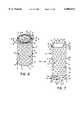
- FIG. 6is an isometric view of the spacer assembly of FIG. 2 following insertion of the end caps into the spacer showing the end caps having a serrated outer side and teeth spaced apart about the periphery of the end cap and engaging the spacer to hold the end cap in place;
- FIG. 7is a cross-sectional view taken along the lines 7--7 of FIG. 6 showing the spacer including a cylindrical side wall defining a passageway and two end caps extending into the passageway and engaging the cylindrical side wall to wedge the end caps and spacer together;
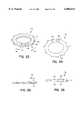
- FIG. 8is a bottom view of an end cap in accordance with an alternative embodiment of the present invention showing the end cap having an oval shape;
- FIG. 9is a side view of the end cap of FIG. 8 showing the end cap having an outer end with a serrated surface, and inner end, and a tapered side wall converging from the outer end toward the inner end;
- FIG. 10.is a top view of the end cap of FIG. 8 showing the serrated surface
- FIG. 11is an isometric view of the spacer of FIG. 2 and end caps in accordance with an alternative embodiment of the present invention showing the end caps having a porous coated top surface and a lip extending about the circumference of the end cap to prevent the end cap from slipping down within a passageway of the surgical mesh tube;
- FIG. 12is a cross-sectional view taken along the lines 12--12 of FIG. 11 showing the tapered side wall of the end cap and the lip engaging peaks of the side wall to prevent the end caps from sliding in the passageway of the spacer;
- FIG. 13is a top view of an end cap in accordance with an alternative embodiment of the present invention showing the end cap to include a solid plate formed with apertures therein;
- FIG. 14is a side view of the end cap of FIG. 13 showing the apertures, in phantom, extending between the outer and inner ends of the end plate;
- FIG. 15is a top view of an end cap in accordance with an alternative embodiment of the present invention showing the end cap including a side wall having a slot formed therein and teeth coupled to the side wall;
- FIG. 16is a perspective view of the end cap of FIG. 15 showing the slot extending between the outer and inner ends of the end cap to permit compression of the end cap;
- FIG. 17is a side view of the end cap of FIG. 15 showing the side wall including a first side wall portion and a tapered second side wall portion;
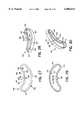
- FIG. 18is a perspective view of an end cap in accordance with an alternative embodiment of the present invention showing the end cap outer and inner ends, a side wall extending between the outer and inner ends, and teeth extending upwardly from the outer end and away from the side wall;
- FIG. 19is a perspective view of an end cap in accordance with an alternative embodiment of the present invention showing the end cap including a side wall having an outer surface and an irregularly shaped inner surface defining a passageway;
- FIG. 20is a top view of the end cap of FIG. 19 showing the inner surface of the side wall defining pockets that are spaced-apart from one another;
- FIG. 21is a front view of the end cap of FIG. 20 showing the slot extending between the outer and inner ends;
- FIG. 22is a side view of the end cap of FIG. 20 showing the side wall including a first side wall portion and a tapered second side wall portion;
- FIG. 23is a perspective view of an end cap in accordance with an alternative embodiment of the present invention showing the end cap including a side wall formed without a chamfer;
- FIG. 24is a top view of the end cap of FIG. 23 showing the outer end including apertures formed therein for receiving a compression instrument;
- FIG. 25is a back view of the end cap of FIG. 23 showing the outer and inner end positioned to lie at an angle relative to one another;
- FIG. 26is a side view of the end cap of FIG. 23 showing the outer and inner end positioned to lie at an angle relative to one another;
- FIG. 27is a top view of an end cap in accordance with an alternative embodiment of the present invention showing the end cap including a crescent-shaped side wall formed for expansion from its original shape to fit over the end of the spacer;
- FIG. 28is a top perspective view of the end cap of FIG. 27 showing the side wall including an inner surface defining a passageway and a lip extending from the side wall into the passageway;
- FIG. 29is a bottom view of the end cap of FIG. 27 showing the lip extending into the passageway.
- FIG. 30is a bottom perspective view of the end cap of FIG. 27.
- End caps 10are provided in accordance with the present invention for use with vertebral body spacers 12 in a spine 14 during disc-replacement or vertebral body replacement surgery to form a spacer assembly 100. As shown in FIG. 1, end cap 10 is coupled to spacer 12 and is suitable for placement into an anterior portion 18 of spine 14. This placement may be done to replace an inter-vertebral disc 20 or to replace a vertebral body 22 or multiple versions of each.
- Spacer 12is, for example, a surgical mesh tube constructed of titanium mesh. Spacer 12 houses bone (not shown) such that spacer 12 fuses to spine 14 to where there will be generally no movement between spacer 12 and spine 14 to reduce a patient's pain.
- Spacer 10includes opposite ends 24, 26 and a cylindrical side wall 30 extending between ends 24, 26 and defining a passageway 32 having a predetermined inner diameter 28. Opposite ends 24, 26 each include peaks 34 and valleys 36 that form detents 38.
- side wall 30has an inner surface 40, an outer surface 42, and apertures 44 extending between inner and outer surfaces 40, 42. As shown in FIG. 2, apertures 44 are generally diamond shaped and positioned to lie in a diamond-like pattern relative to one another.
- apertures 44may have a variety of shapes and sizes and be positioned in a variety of patterns to promote bone ingrowth during the healing process.
- end caps 10are suitable for use with other forms of spacers that are also used in anterior portion 18 of spine 14.
- end caps 10are suitable for use with mesh spacers constructed in a variety of sizes and from a variety of metals, composites, tissue, or bone, or any other type of mesh spacer designed to be placed into spine 14 as a spinal spacer.
- spine 14includes anterior portion 18 and a posterior portion 46.
- spine 14is constructed of vertebral bodies 48, seven of which are cervical vertebral bodies, twelve of which are thoracic vertebral bodies, and five of which are lumber vertebral bodies.
- End caps 10 of the present inventionare coupled to spacer 12 that is delivered to anterior portion 18 or posterior portion 46 of spine 14 whether it is cervical, thoracic or lumber.
- Spacers 12can be designed to replace either disc 20, as shown in FIG. 1, or vertebral body 48. Insertion of spacers 12 into spine is further described in U.S. Patent Application entitled “Insertion Instruments and Method for Delivering a Vertebral Body Spacer,” to Urbahns et. al., filed on Dec. 18, 1998, which is incorporated herein by reference.
- end cap 10is coupled to either end 24, 26 of spacer 12 for use in interbody fusion surgeries. End cap 10, remains at either end 24, 26 of spacer 12 without slipping down within passageway 32.
- end cap 10is formed to include an outer end 50, an inner end 52, and a tapered side wall 54 converging from outer end 50 toward inner end 52.
- side wall 54includes a generally cylindrical inner surface 56 having a constant diameter 58 and defining a passageway 60 and an outer surface 62. While end cap 10 is shown in FIGS.
- outer and inner ends 50, 52may be formed in a variety of shapes to cooperate with a variety of opposite ends 24, 26 of spacers 12 and may be positioned to lie generally parallel to one another or angled relative to one another. It is also appreciated that end caps 10 may vary in size to cooperate with a variety of spacers 12.
- Outer surface 62 of side wall 54cooperates with inner surface 40 of side wall 30 to form a friction lock between end cap 10 and spacer 12, eliminating the necessity of additional parts to couple end cap 10 and spacer 12 together.
- outer surface 62has first outer diameter adjacent 64 to outer end 50 and a second outer diameter 66 adjacent to inner end 52.
- First outer diameter 64is greater than second outer diameter 66 so that outer surface 62 of side wall 54 converges at about an 8 degree taper, as shown in FIG. 3.
- side wall 54may be formed at various angles so long as a friction lock is formed between end cap 10 and spacer 12 in accordance with the present disclosure.
- first outer diameter 64 of side wall 54 adjacent to outer end 50 of end cap 10is generally equivalent to diameter 28 of spacer 14 so that outer end 50 is positioned to lie adjacent to end 24 of spacer 12.
- outer surface 62is further formed to include projections or interdigitating teeth 78 that are spaced apart from another adjacent to outer end 50 of end cap 10.
- teeth 78are positioned on outer surface 62 such that when end cap 10 has been wedged within spacer 12, teeth 78 rest against valleys 36 of opposite ends 24, 26. Because each tooth 78 rests within detent 38, end cap 10 is thus prohibited from slipping within passageway 32 of spacer 12.
- the engagement of side wall 54 and teeth 78 with side wall 30 of spacer 12provides the sole mechanical connection between end cap 10 and spacer 12. While end cap 10 is shown with seven teeth 78, it is appreciated that greater or fewer than seven teeth 78 may be coupled to outer surface 62 in accordance with the present disclosure.
- outer end 50 of end cap 10includes an outer side 68 formed to promote bone ingrowth.
- outer side 68 that promotes bone ingrowthis for example, a porous coated finish 69, as shown in FIGS. 11 and 12.
- An alternative outer side 68 suitable for bone growthis a serrated outer surface 70. See FIGS. 1-7.
- Serrated surface 70 of end cap 10includes peaks 74 and valleys 76. Peaks 74 and valleys 76 provide a rough surface and reduce movement against vertebral body 48.
- porous and serrated outer finishes 70are described, it is appreciated that a variety of anti-skid surfaces that promote bone ingrowth may be used in accordance with the present disclosure.
- the surgeonWhen replacing disc 20 or vertebral bodies 48, the surgeon first removes damaged disc 20 or bodies 48 to create a space 80. See for example disc space 80 in FIG. 1. Once space 80 is formed, the surgeon selects the appropriate size of spacer 12 and at least one corresponding end cap 10. While only one end cap 10 and end 24 of spacer 12 will be discussed hereafter it is appreciated that the description and claims applies to greater than one end cap 10 and end 26. Referring now to FIG. 2, inner end 52 of end cap 10 is aligned with end 24 of spacer 12. Inner end 52 is inserted into passageway 32, as shown in FIG. 7, until outer surface 62 is wedged into engagement with side wall 30 of spacer to form a spacer assembly 100.
- spacer assembly 100may be inserted into space 80 using a variety of surgical techniques. See, for example, U.S. Patent Application entitled “Insertion Instruments and Method for Delivering a Vertebral Body Spacer,” to Urbahns et. al., filed on Dec. 18, 1998, which is incorporated herein by reference.
- an end cap 110has an oval shape. See, FIGS. 8-10.
- End cap 110is formed to cooperate with an oval-shaped spacer (not shown) that is formed identically to spacer 12, except for the oval shape of side wall 30.
- End cap 110is formed similarly to end cap 10 and like reference numerals are use to denote like components.
- end cap 110has a first ring width 164 adjacent to outer end 50 and a second ring width 166 adjacent to inner end 152.
- First ring width 164is greater than second ring width 166, so that outer surface 62 of side wall 54 converges from outer end 50 toward inner end 152 and forms about an 8 degree taper, as shown in FIG. 9.
- end cap 110may be wedged in spacer 12.
- end capincludes ten teeth 78 coupled to outer surface 62. It is appreciated, however, that greater or fewer than ten teeth 78 may be coupled to outer surface 62.
- an end cap 210is provided. End cap 210 is formed similarly to end cap 10 and like reference numerals are used to denote like components. As shown in FIGS. 11 and 12, end cap 210 includes a single projection or outer lip 282 extending from side wall 54 adjacent to outer end 50. Outer lip 282 extends about the circumference of outer end 50 and includes an inner face 284 that rests on peaks 34 of opposite ends 24, 26 respectively to prevent end cap 210 from slipping within passageway 32 of spacer 12. The engagement of side wall 54 and teeth lip 282 with side wall 30 of spacer 12 provides the sole mechanical connection between end cap 210 and spacer 12.
- end cap 310is provided. As shown in FIGS. 13 and 14, end cap 310 is a solid plate 358 shown to have an oval shape and is suited particularly for use with osteoporotic bone. End cap 310 includes an outer end 350, an inner end 352, and a tapered side wall 354 converging from outer end 350 toward inner end 352. Referring now to FIG. 14, side wall 354 includes an outer surface 362. Outer surface 362 of side wall 354 is tapered similarly to outer surface 62 to form a friction lock with spacer 12. The engagement of side wall 354 with side wall 30 of spacer 12 provides the sole mechanical connection between end cap 310 and spacer 12. In addition, apertures 360 extend between outer and inner ends 350, 352.
- end cap 10is shown in FIGS. 13 and 14 with generally oval outer end 350, it is appreciated that end cap 310 may be shaped similarly to end cap 10 or in a variety of shapes to cooperate with a variety of spacers 12 and/or be formed without apertures 360. It is also appreciated that end caps 10 may vary in size to cooperate with a variety of spacers 12. Further, it is appreciated that end cap 310 could be formed to include, outer teeth 54, and/or an outer lip 56.
- End cap 410includes an outer end 414, an inner end 416, and first and second side walls 420, 429 extending between outer and inner ends 414, 416.
- Second side wall 429is a chamfer formed to facilitate inserting end cap 410 into spacer 12 and is tapered similarly to side wall 54 from first side wall portion 420 toward inner end 416.
- Second side wall 429is shown in FIG. 15.
- First and second side walls 420, 429share inside surface 418 defining passageway 422.
- First side wall portion 420also includes outside surface 421 while second side wall 429 includes outside surface 423.
- Six teeth 454extend around the periphery of first side wall portion 420 and are coupled outside surface 421 in the same manner as teeth 78.
- Teeth 454prevent end cap 410 from recessing too far within spacer 12.
- the engagement of first side wall portion 420 and teeth 454 with side wall 30 of spacer 12provides the sole mechanical connection between end cap 410 and spacer 12. It is appreciated that the number of teeth 454 may be greater or fewer than six in accordance with the present disclosure. It is also appreciated that outer and inner ends 414, 416 may be positioned to lie generally parallel to one another or may be angled relative to one another.
- end cap 410also includes inside cross-sectional ends 424, 426 so that end cap 410 has a split-ring shape.
- Cross-sectional ends 424, 426define a slot or cut-out portion 428.
- Slot 428allows end cap 410 to be compressed in direction 430 as it is inserted into passageway 32 of spacer 12.
- End cap 410is shown in its fully opened position in FIGS. 15 and 16 so that a lower outer diameter 432 (see FIG. 17) is greater than diameter 28 of passageway 32.
- end cap 410is compressed together in direction 430, it is sized for insertion within passageway 32 of spacer 12. Once inserted in spacer 12, end cap 410 expands toward its original shape and size thereby pressing against inner surface 40 of spacer 12 to insure a secure and tight fit.
- FIG. 18shows another alternate embodiment of the present invention.
- End cap 510is identical to end cap 410 in nearly all respects and like reference numerals will be used to denote like components.
- End cap 510includes teeth 554 coupled to outer surface 414 and extending away from side wall 420. Thus, outer end 414 is textured to provide further fixation for bone ingrowth.
- end cap 610is provided. End cap 610 is formed similarly to end cap 410 and like reference numerals will be used to denote like components. End cap 610 is formed to include a passageway 622 extending between outer and inner ends 414, 416. Passageway 622 is irregular in shape to maximize a surface area of an inner surface 632 of first and second side walls 420, 429. As shown in FIGS. 19 and 20, inner surface 632 defines pockets 634 spaced apart from one another. While end cap 610 having irregularly shaped passageway 622 with curved pockets 634 is illustrated and described, it is appreciated that end cap 610 may be formed to include a passageway having any number of shapes and sizes in accordance with the present disclosure.
- end cap 710is provided in accordance with the present invention.
- End cap 710is formed similarly to end cap 410 and like reference numerals will be used to denote like components.
- End cap 710includes a side wall 720 extending between inner and outer ends 714, 716.
- Side wall 720is formed without a chamfer.
- inner and outer ends 714, 716are positioned to lie at a predetermined angle 731 relative to one another and are formed to include different surfaces 730, 732, such as, for example porous surface 69 and serrated surface 70. As shown in FIGS.
- end cap 710includes apertures 734 that receive an instrument (not shown) used to compress end cap in direction 430 to be inserted into passageway 32 of spacer 12. Since side wall 720 is not tapered, the surgeon may insert either inner or outer end 714, 716 into passageway 32 so that the desired surface 69, 70 faces away from passageway 32 for engagement with vertebral body 48. It is appreciated that inner and outer ends may be positioned at a variety of angles relative to one another and may be positioned to lie in a generally parallel relationship as well in accordance with the present disclosure.
- FIGS. 27-30illustrate an end cap 810 in accordance with still another embodiment of the present invention.
- End cap 810fits on outer surface 42 of spacer 12 instead of within passageway 32 as previously described end caps 10, 110, 210, 310, 410, 510, 610, and 710.
- End cap 810includes an outer end 814, an inner end 816, and a crescent-shaped side wall 820 extending between outer and inner ends 814, 816. It is appreciated that end cap may be formed into circular, oval, or any complex polynomial shape in accordance with the present disclosure.
- Crescent-shaped side wall 820includes an inside surface 818 defining a passageway 822 and outside surface 821.
- a projection or lip 854extends about the periphery of side wall 820 adjacent to outer end 814 into passageway 822. Lip 854 prevents end cap 810 from recessing too far within spacer 12. It is appreciated that the number of lips 854 may be greater than one in accordance with the present disclosure. It is also appreciated that outer and inner ends 814, 816 may be positioned to lie generally parallel to one another or may be angled relative to one another.
- end cap 810also includes inside cross-sectional ends 824, 826 defining a slot or cut-out portion 828.
- Slot 828allows end cap 810 to expand in direction 830 such than inner surface 818 is sized to extend about outer surface 42 of side wall 30 of spacer 12.
- end cap 810compresses toward its original shape and size shown in FIG. 27, thereby pressing against outer surface 42 of spacer 12 to insure a secure and tight fit.
- Lip 854contacts end 24 of spacer 12 to resist axial loads.
- lipprovides the same support as teeth 78 provide such that end cap 810 cannot recess about side wall 30 of spacer 12 toward end 26.
- the engagement of side wall 820 and lip 854 with side wall 30 of spacer 12provides the sole mechanical connection between end cap 810 and spacer 12.
- end caps 10, 11, 210, 310, 410, 510, 610, 710, and 810are formed to cooperate with spacers to form spacer assemblies for use in spinal surgeries.
- End caps 10, 11, 210, 310, 410, 510, 610, 710, and 810reinforce spacers that are used in spinal and trauma surgeries to increase stability and resistance to shear forces.
- End caps of the present inventionfit within the spacer, on the outside of the spacer, or over the spacer and are coupled to the spacer by a taper or by split-ring forces.
- End caps 10, 11, 210, 310, 410, 510, 610, 710, and 810are preferably self-locking in or on spacer 12.
- end caps of the present inventionmay be formed with a variety of different polynomial shapes to fit a variety of spacer shapes and have a variety of surface coatings or textures to promote bone growth or anti-skid features to prevent movement against bone increasing stability.
- At least one projectionextends from the end cap toward the spacer to prohibit the end cap from slipping within a passageway of the spacer body.
Landscapes
- Health & Medical Sciences (AREA)
- Engineering & Computer Science (AREA)
- Biomedical Technology (AREA)
- Orthopedic Medicine & Surgery (AREA)
- Transplantation (AREA)
- Neurology (AREA)
- Heart & Thoracic Surgery (AREA)
- Oral & Maxillofacial Surgery (AREA)
- Cardiology (AREA)
- Vascular Medicine (AREA)
- Life Sciences & Earth Sciences (AREA)
- Animal Behavior & Ethology (AREA)
- General Health & Medical Sciences (AREA)
- Public Health (AREA)
- Veterinary Medicine (AREA)
- Physical Education & Sports Medicine (AREA)
- Prostheses (AREA)
- Surgical Instruments (AREA)
Abstract
Description
This claims priority under 35 U.S.C. §119(e) of Serial No. 60/068,660 filed Dec. 23, 1997.
The present application relates to spinal instrumentation systems, more particularly to spacer assemblies for use in interbody fusion procedures of the spine. Most particularly, the present invention relates to end caps for use with spacers that are used in spinal surgeries.
There has been a gradual acceptance of interbody fusion as a procedure for a number of spinal disorders. Interbody fusion procedures employ the use of surgical mesh tubes, see for example "Chapter 10: Titanium Surgical Mesh for Vertebral Defect Replacement and Intervertebral Spacers", Gary L. Lowery and Jurgen Harms, Manual of Internal Fixation of the Spine, edited by John S. Thalgott and Max Aebi, Lippincoll-Raven Publishers, Philadelphia, 1996, which is incorporated herein by reference. The surgical mesh tubes are used to reinforce weak, bony tissues in orthopaedic procedures and they act as a structural support for the spine. Moreover, a mesh pattern in the conventional surgical mesh tubes provides access for bone to grow and fuse within the tube. These surgical mesh tubes are often formed of titanium and are available in varying shapes and sizes. In addition, surgical mesh tubes can be trimmed on site by the surgeon to better provide an individual fit for each patient.
Internal rings, connector screws, and fenestrated end plates have been added to the surgical mesh tube. See, for example, "Titanium Surgical Mesh for Vertebral Defect Replacement and Intervertebral Spacers", Gary L. Lowery and Jurgen Harms, Manual of Internal Fixation of the Spine, edited by John S. Thalgott and Max Aebi, Lippincoll-Raven Publishers, Philadelphia, 1996. As discussed in the before mentioned article, conventional rings attach to the contoured mesh through the use of screws. The conventional rings strengthen the surgical mesh tube by acting as a reinforcement to aide in better distributing the axial loads previously taken wholly by the edge of the surgical mesh tube.
According to the present invention a spacer assembly is provided for use in spinal surgeries. The spacer assembly comprises a spacer having opposite ends and a side wall extending between the opposite ends and at least one end cap coupled to at least one of the opposite ends of the spacer. Each end cap includes an inner end facing the spacer, an outer end, and a side wall extending between the inner and outer ends. The side wall of the end cap is formed for engagement with the side wall of the spacer to couple the end cap and spacer together.
In preferred embodiments, the spacer includes a passageway between the opposite ends and the inner end of the end cap extends into the passageway. The side wall of the end cap converges from the outer end toward the inner end to wedge fit the end cap in the spacer. In addition, the end cap includes at least one projection coupled to the side wall and formed to engage the spacer. The projection blocks sliding movement of the end cap in the passageway of the spacer. Also, the outer end includes an outer surface that promotes bone ingrowth, such as for example a porous coating or a serrated surface. Preferably, the engagement of the end cap side wall and the projection with the side wall of thespacer 12 provides the sole mechanical connection between the end cap and the spacer.
Alternatively, the side wall of the end cap is formed to include a slot extending between the outer and inner ends. The slot allows the side wall of the end cap to be compressed as it is inserted into the passageway of the spacer. Once positioned in the passageway, the side wall expands toward the side wall of the spacer to friction lock the end cap in the passageway of the spacer. At least one projection extends from the side wall of the compressible end cap for engagement with the spacer to block sliding movement of the end cap in the passageway.
Still further, the side wall of the spacer includes an outer surface and an alternative end cap is formed to extend over the opposite end of spacer and be coupled to the outer surface. The end cap includes an outer end, an inner end, and a side wall that extends between the outer and inner ends. In addition, the side wall includes a slot extending between the outer and inner ends. The slot allows the side wall of the end cap to be expanded as it is placed about the end of the spacer. Once positioned about the outer surface of the spacer, the side wall of the end cap contracts toward the side wall of the spacer to friction lock the end cap on the side wall of the spacer. At least one projection extends from the side wall of the compressible end cap for engagement with the spacer to block sliding movement of the end cap in the passageway.
Additional features of the invention will become apparent to those skilled in the art upon consideration of the following detailed description of preferred embodiments exemplifying the best mode of carrying out the invention as presently perceived.
FIG. 1 is a perspective view of an anterior portion of a spine, a spacer assembly in accordance with the present invention, and showing a portion of one disc removed from the spine to form a disc space and the inter-vertebral spacer sized for extension into the disc space;
FIG. 2 is an exploded isometric view of the spacer assembly of FIG. 1 showing the spacer assembly including a spacer and two end caps of the present invention;
FIG. 3 is a side view of the end cap of FIG. 2 showing the end cap including an outer end, an inner surface, a tapered side wall extending between the outer and inner surfaces, teeth extending outwardly from the side wall, and the outer end including a serrated surface;
FIG. 4 is a bottom view of the end cap of FIG. 3 showing the side wall including an outer surface and an inner surface defining a passageway and the teeth extending from the outer surface in a spaced-apart relationship relative to one another;
FIG. 5 is a top view of the end cap of FIG. 3 showing the serrated surface of the outer end;
FIG. 6 is an isometric view of the spacer assembly of FIG. 2 following insertion of the end caps into the spacer showing the end caps having a serrated outer side and teeth spaced apart about the periphery of the end cap and engaging the spacer to hold the end cap in place;
FIG. 7 is a cross-sectional view taken along the lines 7--7 of FIG. 6 showing the spacer including a cylindrical side wall defining a passageway and two end caps extending into the passageway and engaging the cylindrical side wall to wedge the end caps and spacer together;
FIG. 8 is a bottom view of an end cap in accordance with an alternative embodiment of the present invention showing the end cap having an oval shape;
FIG. 9 is a side view of the end cap of FIG. 8 showing the end cap having an outer end with a serrated surface, and inner end, and a tapered side wall converging from the outer end toward the inner end;
FIG. 10. is a top view of the end cap of FIG. 8 showing the serrated surface;
FIG. 11 is an isometric view of the spacer of FIG. 2 and end caps in accordance with an alternative embodiment of the present invention showing the end caps having a porous coated top surface and a lip extending about the circumference of the end cap to prevent the end cap from slipping down within a passageway of the surgical mesh tube;
FIG. 12 is a cross-sectional view taken along thelines 12--12 of FIG. 11 showing the tapered side wall of the end cap and the lip engaging peaks of the side wall to prevent the end caps from sliding in the passageway of the spacer;
FIG. 13 is a top view of an end cap in accordance with an alternative embodiment of the present invention showing the end cap to include a solid plate formed with apertures therein;
FIG. 14 is a side view of the end cap of FIG. 13 showing the apertures, in phantom, extending between the outer and inner ends of the end plate;
FIG. 15 is a top view of an end cap in accordance with an alternative embodiment of the present invention showing the end cap including a side wall having a slot formed therein and teeth coupled to the side wall;
FIG. 16 is a perspective view of the end cap of FIG. 15 showing the slot extending between the outer and inner ends of the end cap to permit compression of the end cap;
FIG. 17 is a side view of the end cap of FIG. 15 showing the side wall including a first side wall portion and a tapered second side wall portion;
FIG. 18 is a perspective view of an end cap in accordance with an alternative embodiment of the present invention showing the end cap outer and inner ends, a side wall extending between the outer and inner ends, and teeth extending upwardly from the outer end and away from the side wall;
FIG. 19 is a perspective view of an end cap in accordance with an alternative embodiment of the present invention showing the end cap including a side wall having an outer surface and an irregularly shaped inner surface defining a passageway;
FIG. 20 is a top view of the end cap of FIG. 19 showing the inner surface of the side wall defining pockets that are spaced-apart from one another;
FIG. 21 is a front view of the end cap of FIG. 20 showing the slot extending between the outer and inner ends;
FIG. 22 is a side view of the end cap of FIG. 20 showing the side wall including a first side wall portion and a tapered second side wall portion;
FIG. 23 is a perspective view of an end cap in accordance with an alternative embodiment of the present invention showing the end cap including a side wall formed without a chamfer;
FIG. 24 is a top view of the end cap of FIG. 23 showing the outer end including apertures formed therein for receiving a compression instrument;
FIG. 25 is a back view of the end cap of FIG. 23 showing the outer and inner end positioned to lie at an angle relative to one another;
FIG. 26 is a side view of the end cap of FIG. 23 showing the outer and inner end positioned to lie at an angle relative to one another;
FIG. 27 is a top view of an end cap in accordance with an alternative embodiment of the present invention showing the end cap including a crescent-shaped side wall formed for expansion from its original shape to fit over the end of the spacer;
FIG. 28 is a top perspective view of the end cap of FIG. 27 showing the side wall including an inner surface defining a passageway and a lip extending from the side wall into the passageway;
FIG. 29 is a bottom view of the end cap of FIG. 27 showing the lip extending into the passageway; and
FIG. 30 is a bottom perspective view of the end cap of FIG. 27.
End caps 10 are provided in accordance with the present invention for use with vertebral body spacers 12 in aspine 14 during disc-replacement or vertebral body replacement surgery to form aspacer assembly 100. As shown in FIG. 1,end cap 10 is coupled tospacer 12 and is suitable for placement into ananterior portion 18 ofspine 14. This placement may be done to replace aninter-vertebral disc 20 or to replace avertebral body 22 or multiple versions of each.
Referring now to FIG. 1,spine 14 includesanterior portion 18 and aposterior portion 46. In addition,spine 14 is constructed ofvertebral bodies 48, seven of which are cervical vertebral bodies, twelve of which are thoracic vertebral bodies, and five of which are lumber vertebral bodies. End caps 10 of the present invention are coupled tospacer 12 that is delivered toanterior portion 18 orposterior portion 46 ofspine 14 whether it is cervical, thoracic or lumber.Spacers 12 can be designed to replace eitherdisc 20, as shown in FIG. 1, orvertebral body 48. Insertion ofspacers 12 into spine is further described in U.S. Patent Application entitled "Insertion Instruments and Method for Delivering a Vertebral Body Spacer," to Urbahns et. al., filed on Dec. 18, 1998, which is incorporated herein by reference.
As shown in FIG. 2,end cap 10 is coupled to either end 24, 26 ofspacer 12 for use in interbody fusion surgeries.End cap 10, remains at eitherend spacer 12 without slipping down withinpassageway 32. As shown in FIGS. 2-5,end cap 10 is formed to include anouter end 50, aninner end 52, and atapered side wall 54 converging fromouter end 50 towardinner end 52. Referring now to FIG. 4,side wall 54 includes a generally cylindricalinner surface 56 having aconstant diameter 58 and defining apassageway 60 and anouter surface 62. Whileend cap 10 is shown in FIGS. 4 and 5 with generally circular outer and inner ends 50, 52, it is appreciated that outer and inner ends 50, 52 may be formed in a variety of shapes to cooperate with a variety of opposite ends 24, 26 ofspacers 12 and may be positioned to lie generally parallel to one another or angled relative to one another. It is also appreciated that end caps 10 may vary in size to cooperate with a variety ofspacers 12.
As shown in FIG. 3,outer surface 62 is further formed to include projections or interdigitatingteeth 78 that are spaced apart from another adjacent toouter end 50 ofend cap 10. Referring now to FIGS. 6 and 7,teeth 78 are positioned onouter surface 62 such that whenend cap 10 has been wedged withinspacer 12,teeth 78 rest againstvalleys 36 of opposite ends 24, 26. Because eachtooth 78 rests withindetent 38,end cap 10 is thus prohibited from slipping withinpassageway 32 ofspacer 12. The engagement ofside wall 54 andteeth 78 withside wall 30 ofspacer 12 provides the sole mechanical connection betweenend cap 10 andspacer 12. Whileend cap 10 is shown with seventeeth 78, it is appreciated that greater or fewer than seventeeth 78 may be coupled toouter surface 62 in accordance with the present disclosure.
Referring now to FIG. 6,outer end 50 ofend cap 10 includes anouter side 68 formed to promote bone ingrowth. One type ofouter side 68 that promotes bone ingrowth is for example, a porouscoated finish 69, as shown in FIGS. 11 and 12. An alternativeouter side 68 suitable for bone growth is a serratedouter surface 70. See FIGS. 1-7.Serrated surface 70 ofend cap 10 includespeaks 74 andvalleys 76.Peaks 74 andvalleys 76 provide a rough surface and reduce movement againstvertebral body 48. Although porous and serratedouter finishes 70 are described, it is appreciated that a variety of anti-skid surfaces that promote bone ingrowth may be used in accordance with the present disclosure.
When replacingdisc 20 orvertebral bodies 48, the surgeon first removes damageddisc 20 orbodies 48 to create aspace 80. See forexample disc space 80 in FIG. 1. Oncespace 80 is formed, the surgeon selects the appropriate size ofspacer 12 and at least onecorresponding end cap 10. While only oneend cap 10 and end 24 ofspacer 12 will be discussed hereafter it is appreciated that the description and claims applies to greater than oneend cap 10 andend 26. Referring now to FIG. 2,inner end 52 ofend cap 10 is aligned withend 24 ofspacer 12.Inner end 52 is inserted intopassageway 32, as shown in FIG. 7, untilouter surface 62 is wedged into engagement withside wall 30 of spacer to form aspacer assembly 100. At that time,teeth 78 will be positioned to lie withindetents 38 preventing further migration ofend cap 10 intopassageway 32 ofspacer 12. Onceend cap 10 is coupled tospacer 12,spacer assembly 100 may be inserted intospace 80 using a variety of surgical techniques. See, for example, U.S. Patent Application entitled "Insertion Instruments and Method for Delivering a Vertebral Body Spacer," to Urbahns et. al., filed on Dec. 18, 1998, which is incorporated herein by reference.
In an alternative embodiment of the present invention it is provided that anend cap 110 has an oval shape. See, FIGS. 8-10.End cap 110 is formed to cooperate with an oval-shaped spacer (not shown) that is formed identically tospacer 12, except for the oval shape ofside wall 30.End cap 110 is formed similarly to endcap 10 and like reference numerals are use to denote like components. As shown in FIG. 8,end cap 110 has afirst ring width 164 adjacent toouter end 50 and asecond ring width 166 adjacent to inner end 152.First ring width 164 is greater thansecond ring width 166, so thatouter surface 62 ofside wall 54 converges fromouter end 50 toward inner end 152 and forms about an 8 degree taper, as shown in FIG. 9. It is appreciated that the angle of taper may vary so long asend cap 110 may be wedged inspacer 12. Additionally, end cap includes tenteeth 78 coupled toouter surface 62. It is appreciated, however, that greater or fewer than tenteeth 78 may be coupled toouter surface 62.
In an alternative embodiment of the present invention, anend cap 210 is provided.End cap 210 is formed similarly to endcap 10 and like reference numerals are used to denote like components. As shown in FIGS. 11 and 12,end cap 210 includes a single projection orouter lip 282 extending fromside wall 54 adjacent toouter end 50.Outer lip 282 extends about the circumference ofouter end 50 and includes aninner face 284 that rests onpeaks 34 of opposite ends 24, 26 respectively to preventend cap 210 from slipping withinpassageway 32 ofspacer 12. The engagement ofside wall 54 andteeth lip 282 withside wall 30 ofspacer 12 provides the sole mechanical connection betweenend cap 210 andspacer 12.
In still another embodiment of the present invention anend cap 310 is provided. As shown in FIGS. 13 and 14,end cap 310 is asolid plate 358 shown to have an oval shape and is suited particularly for use with osteoporotic bone.End cap 310 includes anouter end 350, aninner end 352, and atapered side wall 354 converging fromouter end 350 towardinner end 352. Referring now to FIG. 14,side wall 354 includes anouter surface 362.Outer surface 362 ofside wall 354 is tapered similarly toouter surface 62 to form a friction lock withspacer 12. The engagement ofside wall 354 withside wall 30 ofspacer 12 provides the sole mechanical connection betweenend cap 310 andspacer 12. In addition,apertures 360 extend between outer and inner ends 350, 352. Whileend cap 10 is shown in FIGS. 13 and 14 with generally ovalouter end 350, it is appreciated thatend cap 310 may be shaped similarly to endcap 10 or in a variety of shapes to cooperate with a variety ofspacers 12 and/or be formed withoutapertures 360. It is also appreciated that end caps 10 may vary in size to cooperate with a variety ofspacers 12. Further, it is appreciated thatend cap 310 could be formed to include,outer teeth 54, and/or anouter lip 56.
Another embodiment of the present invention is shown in FIGS. 15-17.End cap 410 includes anouter end 414, aninner end 416, and first andsecond side walls Second side wall 429 is a chamfer formed to facilitate insertingend cap 410 intospacer 12 and is tapered similarly toside wall 54 from firstside wall portion 420 towardinner end 416.Second side wall 429 is shown in FIG. 15. First andsecond side walls surface 418 definingpassageway 422. Firstside wall portion 420 also includes outsidesurface 421 whilesecond side wall 429 includesoutside surface 423. Sixteeth 454 extend around the periphery of firstside wall portion 420 and are coupled outsidesurface 421 in the same manner asteeth 78.Teeth 454 preventend cap 410 from recessing too far withinspacer 12. The engagement of firstside wall portion 420 andteeth 454 withside wall 30 ofspacer 12 provides the sole mechanical connection betweenend cap 410 andspacer 12. It is appreciated that the number ofteeth 454 may be greater or fewer than six in accordance with the present disclosure. It is also appreciated that outer and inner ends 414, 416 may be positioned to lie generally parallel to one another or may be angled relative to one another.
As shown in FIGS. 15 and 16,end cap 410 also includes inside cross-sectional ends 424, 426 so thatend cap 410 has a split-ring shape. Cross-sectional ends 424, 426 define a slot or cut-outportion 428.Slot 428 allowsend cap 410 to be compressed indirection 430 as it is inserted intopassageway 32 ofspacer 12.End cap 410 is shown in its fully opened position in FIGS. 15 and 16 so that a lower outer diameter 432 (see FIG. 17) is greater thandiameter 28 ofpassageway 32. Asend cap 410 is compressed together indirection 430, it is sized for insertion withinpassageway 32 ofspacer 12. Once inserted inspacer 12,end cap 410 expands toward its original shape and size thereby pressing againstinner surface 40 ofspacer 12 to insure a secure and tight fit.
FIG. 18 shows another alternate embodiment of the present invention.End cap 510 is identical to endcap 410 in nearly all respects and like reference numerals will be used to denote like components.End cap 510 includesteeth 554 coupled toouter surface 414 and extending away fromside wall 420. Thus,outer end 414 is textured to provide further fixation for bone ingrowth.
As shown in FIGS. 19-22,end cap 610 is provided.End cap 610 is formed similarly to endcap 410 and like reference numerals will be used to denote like components.End cap 610 is formed to include apassageway 622 extending between outer and inner ends 414, 416.Passageway 622 is irregular in shape to maximize a surface area of aninner surface 632 of first andsecond side walls inner surface 632 definespockets 634 spaced apart from one another. Whileend cap 610 having irregularly shapedpassageway 622 withcurved pockets 634 is illustrated and described, it is appreciated thatend cap 610 may be formed to include a passageway having any number of shapes and sizes in accordance with the present disclosure.
Referring now to FIGS. 23-26,end cap 710 is provided in accordance with the present invention.End cap 710 is formed similarly to endcap 410 and like reference numerals will be used to denote like components.End cap 710 includes aside wall 720 extending between inner andouter ends Side wall 720 is formed without a chamfer. In addition, as shown in FIGS. 25 and 26, inner andouter ends different surfaces porous surface 69 andserrated surface 70. As shown in FIGS. 23 and 24,end cap 710 includesapertures 734 that receive an instrument (not shown) used to compress end cap indirection 430 to be inserted intopassageway 32 ofspacer 12. Sinceside wall 720 is not tapered, the surgeon may insert either inner orouter end passageway 32 so that the desiredsurface passageway 32 for engagement withvertebral body 48. It is appreciated that inner and outer ends may be positioned at a variety of angles relative to one another and may be positioned to lie in a generally parallel relationship as well in accordance with the present disclosure.
FIGS. 27-30 illustrate anend cap 810 in accordance with still another embodiment of the present invention.End cap 810 fits onouter surface 42 ofspacer 12 instead of withinpassageway 32 as previously describedend caps End cap 810 includes anouter end 814, aninner end 816, and a crescent-shapedside wall 820 extending between outer and inner ends 814, 816. It is appreciated that end cap may be formed into circular, oval, or any complex polynomial shape in accordance with the present disclosure.
Crescent-shapedside wall 820 includes aninside surface 818 defining apassageway 822 and outsidesurface 821. A projection orlip 854 extends about the periphery ofside wall 820 adjacent toouter end 814 intopassageway 822.Lip 854 preventsend cap 810 from recessing too far withinspacer 12. It is appreciated that the number oflips 854 may be greater than one in accordance with the present disclosure. It is also appreciated that outer and inner ends 814, 816 may be positioned to lie generally parallel to one another or may be angled relative to one another.
As shown in FIGS. 27 and 28,end cap 810 also includes inside cross-sectional ends 824, 826 defining a slot or cut-outportion 828.Slot 828 allowsend cap 810 to expand indirection 830 such thaninner surface 818 is sized to extend aboutouter surface 42 ofside wall 30 ofspacer 12. Once positioned aboutend 24 ofspacer 12,end cap 810 compresses toward its original shape and size shown in FIG. 27, thereby pressing againstouter surface 42 ofspacer 12 to insure a secure and tight fit.Lip 854 contacts end 24 ofspacer 12 to resist axial loads. In addition, lip provides the same support asteeth 78 provide such thatend cap 810 cannot recess aboutside wall 30 ofspacer 12 towardend 26. The engagement ofside wall 820 andlip 854 withside wall 30 ofspacer 12 provides the sole mechanical connection betweenend cap 810 andspacer 12.
Therefore, end caps 10, 11, 210, 310, 410, 510, 610, 710, and 810 are formed to cooperate with spacers to form spacer assemblies for use in spinal surgeries. End caps 10, 11, 210, 310, 410, 510, 610, 710, and 810 reinforce spacers that are used in spinal and trauma surgeries to increase stability and resistance to shear forces. End caps of the present invention fit within the spacer, on the outside of the spacer, or over the spacer and are coupled to the spacer by a taper or by split-ring forces. End caps 10, 11, 210, 310, 410, 510, 610, 710, and 810 are preferably self-locking in or onspacer 12. In addition, end caps of the present invention may be formed with a variety of different polynomial shapes to fit a variety of spacer shapes and have a variety of surface coatings or textures to promote bone growth or anti-skid features to prevent movement against bone increasing stability. At least one projection extends from the end cap toward the spacer to prohibit the end cap from slipping within a passageway of the spacer body.
Although the invention has been described in detail with reference to a preferred embodiment, variations and modifications exist within the scope and spirit of the invention as described and defined in the following claims.
Claims (33)
1. A spacer assembly for use in spinal surgeries, the assembly comprising:
a spacer formed to include opposite ends and a side wall extending between the opposite ends, and
at least one end cap coupled to at least one of the opposite ends, each of the at least one end caps including an inner end facing the spacer, an outer end, and a side wall extending between the inner and outer ends and engaging the side wall of the spacer to provide a mechanical connection between the at least one cap and the spacer, the side wall of the end cap including a slot extending between the outer and inner ends.
2. The spacer assembly of claim 1, wherein the spacer includes a passageway extending between the opposite ends and the inner end of the end cap extends into the passageway.
3. The spacer assembly of claim 2, wherein the side wall of the end cap converges from the outer end toward the inner end.
4. The spacer assembly of claim 3, wherein the end cap includes a projection coupled to the side wall of the end cap and formed for engagement with the spacer.
5. The spacer assembly of claim 3, wherein the outer end is formed to include a porous coating.
6. The spacer assembly of claim 3, wherein the outer end includes a serrated surface.
7. The spacer assembly of claim 2, wherein the end cap includes a projection that extends away from the side wall of the end cap into engagement with the spacer.
8. The spacer assembly of claim 2, wherein the end cap includes projections spaced-apart from one another and formed for engagement with the spacer.
9. The spacer assembly of claim 1, wherein the end cap includes projections spaced-apart from one another and formed for engagement with the spacer.
10. The spacer assembly of claim 1, wherein the side wall of the end cap includes an inner surface that defines a passageway between the inner and outer ends.
11. The spacer assembly of claim 10, wherein the inner surface of the side wall is generally cylindrical in shape.
12. The spacer assembly of claim 1, wherein the end cap is formed as a solid plate including apertures extending between the outer and inner surfaces.
13. The spacer assembly of claim 1, wherein at least one of the ends of the spacer includes peaks and valleys.
14. The spacer assembly of claim 13, wherein the end cap includes projections coupled to the side wall of the end cap and formed for extension between the peaks and engagement with the valleys of the spacer.
15. The spacer assembly of claim 13, wherein the end cap includes a projection coupled to the side wall of the end cap and formed for engagement with the peaks of the spacer.
16. A spacer assembly for use in spinal surgeries, the assembly comprising:
a spacer formed to include opposite ends and a side wall extending between the opposite ends, and
at least one end cap coupled to at least one of the opposite ends, each of the at least one end caps including an inner end facing the spacer, an outer end, and a side wall extending between the inner and outer ends and engaging the side wall of the spacer to provide a mechanical connection between the at least one cap and the spacer and the side wall of the spacer includes an outer surface and the side wall of the end cap is coupled to the outer surface.
17. The spacer assembly of claim 16, wherein the side wall of the end cap includes a slot extending between the outer and inner ends.
18. The spacer assembly of claim 17, wherein the side wall of the end cap defines a passageway and the end cap further includes at least one projection extending into the passageway of the side wall and engaging the spacer.
19. A spacer assembly for use in spinal surgeries, the assembly comprising:
a spacer formed to include opposite ends and a side wall extending between the opposite ends, and
end caps coupled to the opposite ends respectively, each of said end caps including an inner end facing the spacer, an outer end, a side wall extending between the inner and outer ends, and at least one projection extending from the side wall, the engagement of the end cap side wall with the side wall of the spacer and the at least one projection with the side wall with the respective opposite end of the spacer providing the sole mechanical connection between the spacer and the end caps, and the side wall of the end cap including a slot extending between the inner and outer ends.
20. The spacer assembly of claim 19, wherein the opposite ends are formed to include peaks and valleys.
21. The spacer assembly of claim 20, wherein the at least one projection engages at least one of the peaks of the respective opposite ends.
22. The spacer assembly of claim 20, wherein the at least one projection engages at least one of the valleys of the respective opposite ends.
23. The spacer assembly of claim 19, wherein the spacer includes a passageway extending between the opposite ends and the inner end of the end cap extends into the passageway.
24. The spacer assembly of claim 19, wherein the side wall of the spacer includes an outer surface and the side wall of the end cap is coupled to the outer surface.
25. The end cap of claim 19, wherein the outer end of the end cap is generally circular in shape.
26. The end cap of claim 19, wherein the outer end of the end cap includes a coating formed to promote bone growth.
27. The end cap of claim 19, wherein the side wall of the end cap includes a generally cylindrical inner surface defining a passageway.
28. A spacer assembly for use in spinal surgeries, the assembly comprising:
a spacer formed to include opposite ends and a side wall extending between the opposite ends, and
end caps coupled to the opposite ends respectively, each of said end caps including an inner end facing the spacer, an outer end, a side wall extending between the inner and outer ends, and at least one projection extending from the side wall, the engagement of the end cap side wall with the side wall of the spacer and the at least one projection with the side wall with the respective opposite end of the spacer providing the sole mechanical connection between the spacer and the end caps, the spacer including a passageway extending between the opposite ends and the inner end of the end cap extends into the passageway, and the side wall of the end cap is tapered.
29. A spacer assembly for use in spinal surgeries, the assembly comprising:
a spacer formed to include opposite ends and a side wall extending between the opposite ends, and
end caps coupled to the opposite ends respectively, each of said end caps including an inner end facing the spacer, an outer end, a side wall extending between the inner and outer ends, and at least one projection extending from the side wall, the engagement of the end cap side wall with the side wall of the spacer and the at least one projection with the side wall with the respective opposite end of the spacer providing the sole mechanical connection between the spacer and the end caps, the side wall of the spacer includes an outer surface and the side wall of the end cap is coupled to the outer surface and the side wall of the end cap includes a slot extending between the outer and inner ends.
30. An end cap formed for use with a spacer having opposite ends in a spinal surgery, the end cap comprising:
an inner end, an outer end, a side wall extending between the inner and outer ends, and at least one projection extending from the side wall, the side wall including a slot extending between the outer and inner ends and being adapted to provide a mechanical connection between the end cap and the spacer to couple the end cap and spacer together.
31. The end cap of claim 30, wherein the side wall includes an inner surface defining a passageway and an outer surface.
32. The end cap of claim 31, wherein the inner surface of the side wall is generally cylindrical in shape.
33. A spacer assembly for use in spinal surgeries, the assembly comprising:
a spacer formed to include opposite ends and a side wall extending between the opposite ends, and
at least one end cap coupled to at least one of the opposite ends, each of the at least one end caps including an inner end facing the spacer, an outer end having a serrated surface, and a side wall extending between the inner and outer ends and engaging the side wall of the spacer to provide a mechanical connection between the at least one cap and the spacer,
wherein the side wall of the end cap includes a slot extending between the outer and inner ends.
Priority Applications (2)
| Application Number | Priority Date | Filing Date | Title |
|---|---|---|---|
| US09/218,745US6086613A (en) | 1997-12-23 | 1998-12-22 | Spacer assembly for use in spinal surgeries |
| US10/056,909US6776798B2 (en) | 1997-12-23 | 2002-01-25 | Spacer assembly for use in spinal surgeries having end cap which includes serrated surface |
Applications Claiming Priority (2)
| Application Number | Priority Date | Filing Date | Title |
|---|---|---|---|
| US6866097P | 1997-12-23 | 1997-12-23 | |
| US09/218,745US6086613A (en) | 1997-12-23 | 1998-12-22 | Spacer assembly for use in spinal surgeries |
Related Child Applications (1)
| Application Number | Title | Priority Date | Filing Date |
|---|---|---|---|
| US59153000AContinuation | 1997-12-23 | 2000-06-09 |
Publications (1)
| Publication Number | Publication Date |
|---|---|
| US6086613Atrue US6086613A (en) | 2000-07-11 |
Family
ID=22083948
Family Applications (2)
| Application Number | Title | Priority Date | Filing Date |
|---|---|---|---|
| US09/218,745Expired - LifetimeUS6086613A (en) | 1997-12-23 | 1998-12-22 | Spacer assembly for use in spinal surgeries |
| US10/056,909Expired - LifetimeUS6776798B2 (en) | 1997-12-23 | 2002-01-25 | Spacer assembly for use in spinal surgeries having end cap which includes serrated surface |
Family Applications After (1)
| Application Number | Title | Priority Date | Filing Date |
|---|---|---|---|
| US10/056,909Expired - LifetimeUS6776798B2 (en) | 1997-12-23 | 2002-01-25 | Spacer assembly for use in spinal surgeries having end cap which includes serrated surface |
Country Status (9)
| Country | Link |
|---|---|
| US (2) | US6086613A (en) |
| EP (1) | EP1041946B1 (en) |
| JP (1) | JP4097896B2 (en) |
| KR (1) | KR20010033466A (en) |
| CN (1) | CN1253130C (en) |
| AU (1) | AU734942B2 (en) |
| CA (1) | CA2313467C (en) |
| DE (1) | DE69822508T2 (en) |
| WO (1) | WO1999032055A1 (en) |
Cited By (179)
| Publication number | Priority date | Publication date | Assignee | Title |
|---|---|---|---|---|
| US6375681B1 (en)* | 1998-06-23 | 2002-04-23 | Ebi, L.P. | Vertebral body replacement |
| US6447543B1 (en)* | 1999-09-28 | 2002-09-10 | Sulzer Orthopedics Ltd. | Basket-like container for implanting bone tissue |
| US20020165550A1 (en)* | 1999-10-21 | 2002-11-07 | George Frey | Devices and techniques for a posterior lateral disc space approach |
| US6524341B2 (en)* | 1998-10-15 | 2003-02-25 | Synthes (Usa) | Telescopic vertebral prosthesis |
| US20030045935A1 (en)* | 2001-02-28 | 2003-03-06 | Angelucci Christopher M. | Laminoplasty implants and methods of use |
| US20030078660A1 (en)* | 2001-02-15 | 2003-04-24 | Dale Clifford | Orthopedic implant and method for orthopedic treatment |
| US6572654B1 (en) | 2000-10-04 | 2003-06-03 | Albert N. Santilli | Intervertebral spacer |
| US6585770B1 (en) | 1997-06-02 | 2003-07-01 | Sdgi Holdings, Inc. | Devices for supporting bony structures |
| US20030176925A1 (en)* | 2002-03-15 | 2003-09-18 | Francois Paponneau | Vertebral body spacer having variable wedged endplates |
| US6635087B2 (en) | 2001-08-29 | 2003-10-21 | Christopher M. Angelucci | Laminoplasty implants and methods of use |
| US6648915B2 (en)* | 1999-12-23 | 2003-11-18 | John A. Sazy | Intervertebral cage and method of use |
| US6656224B2 (en)* | 1998-06-17 | 2003-12-02 | Howmedica Osteonics Corp. | Artificial intervertebral disc |
| US6660038B2 (en)* | 2000-03-22 | 2003-12-09 | Synthes (Usa) | Skeletal reconstruction cages |
| US6673075B2 (en) | 2001-02-23 | 2004-01-06 | Albert N. Santilli | Porous intervertebral spacer |
| US20040030346A1 (en)* | 1999-10-21 | 2004-02-12 | George Frey | Devices and techniques for a posterior lateral disc space approach |
| US6719794B2 (en) | 2001-05-03 | 2004-04-13 | Synthes (U.S.A.) | Intervertebral implant for transforaminal posterior lumbar interbody fusion procedure |
| US20040073314A1 (en)* | 2002-03-21 | 2004-04-15 | White John L. | Vertebral body and disc space replacement devices |
| US6743257B2 (en) | 2000-12-19 | 2004-06-01 | Cortek, Inc. | Dynamic implanted intervertebral spacer |
| US20040122518A1 (en)* | 2002-12-19 | 2004-06-24 | Rhoda William S. | Intervertebral implant |
| US20040126407A1 (en)* | 2002-10-23 | 2004-07-01 | Falahee Mark H. | Intervertebral cage designs |
| US6758862B2 (en) | 2002-03-21 | 2004-07-06 | Sdgi Holdings, Inc. | Vertebral body and disc space replacement devices |
| US6764491B2 (en) | 1999-10-21 | 2004-07-20 | Sdgi Holdings, Inc. | Devices and techniques for a posterior lateral disc space approach |
| USD493533S1 (en) | 2003-02-14 | 2004-07-27 | Nuvasive, Inc. | Intervertebral implant |
| US6776798B2 (en) | 1997-12-23 | 2004-08-17 | Depuy Acromed, Inc. | Spacer assembly for use in spinal surgeries having end cap which includes serrated surface |
| US6783547B2 (en) | 2002-04-05 | 2004-08-31 | Howmedica Corp. | Apparatus for fusing adjacent bone structures |
| US20040176843A1 (en)* | 2003-03-06 | 2004-09-09 | Rafail Zubok | Instrumentation and methods for use in implanting a cervical disc replacement device |
| US20040199252A1 (en)* | 2003-04-03 | 2004-10-07 | William Sears | Apparatus and method for supporting vertebral bodies |
| US20050004671A1 (en)* | 2003-07-01 | 2005-01-06 | Thomas Ross | Spinal spacer assembly |
| US20050033425A1 (en)* | 2003-08-04 | 2005-02-10 | Schwab Frank J. | Bone supporting devices with bio-absorbable end members |
| US20050085910A1 (en)* | 2003-10-16 | 2005-04-21 | Sweeney Patrick J. | Vertebral prosthesis |
| US20050090898A1 (en)* | 2003-10-22 | 2005-04-28 | Sdgi Holdings, Inc. | Vertebral body replacement implant |
| US20050131543A1 (en)* | 2003-12-10 | 2005-06-16 | Axiomed Spine Corporation | Method and apparatus for replacing a damaged spinal disc |
| US20050143819A1 (en)* | 2002-06-14 | 2005-06-30 | Falahee Mark H. | Percutaneous posterior lateral in-situ cage |
| US20050154459A1 (en)* | 2003-10-20 | 2005-07-14 | Howard Wolek | Vertebral body replacement apparatus and method |
| US20050159814A1 (en)* | 2004-01-15 | 2005-07-21 | Sdgi Holdings, Inc. | Universal interference cleat |
| US6929662B1 (en)* | 1999-02-04 | 2005-08-16 | Synthes (Usa) | End member for a bone fusion implant |
| US20050187634A1 (en)* | 2003-03-20 | 2005-08-25 | Berry Bret M. | Height adjustable vertebral body and disc space replacement devices |
| US6966929B2 (en) | 2002-10-29 | 2005-11-22 | St. Francis Medical Technologies, Inc. | Artificial vertebral disk replacement implant with a spacer |
| US20050267471A1 (en)* | 2004-05-04 | 2005-12-01 | Lutz Biedermann | Flexible space holder |
| US6974480B2 (en) | 2001-05-03 | 2005-12-13 | Synthes (Usa) | Intervertebral implant for transforaminal posterior lumbar interbody fusion procedure |
| US20060025861A1 (en)* | 2000-03-10 | 2006-02-02 | Sdgi Holdings, Inc. | Synthetic reinforced interbody fusion implants |
| US20060074490A1 (en)* | 2004-10-01 | 2006-04-06 | Sweeney Patrick J | Vertebral prosthesis and spinal fixation system |
| US20060149384A1 (en)* | 2003-04-04 | 2006-07-06 | Theken Disc, Llc | Artificial disc prosthesis |
| US7083649B2 (en) | 2002-10-29 | 2006-08-01 | St. Francis Medical Technologies, Inc. | Artificial vertebral disk replacement implant with translating pivot point |
| US20060231672A1 (en)* | 2005-04-15 | 2006-10-19 | E5 Products, Inc. | Electrician's caddy |
| US20060241762A1 (en)* | 2003-12-11 | 2006-10-26 | Deltacor Gmbh | Height-adjustable spinal implant and operating instrument for the implant |
| US20070027544A1 (en)* | 2005-07-28 | 2007-02-01 | Altiva Corporation | Spinal cage implant |
| US20070073395A1 (en)* | 2003-04-11 | 2007-03-29 | Daniel Baumgartner | Anchoring means for intervertebral implants |
| US20070129805A1 (en)* | 2005-12-01 | 2007-06-07 | Braddock Danny H Jr | End device for a vertebral implant |
| US20070162129A1 (en)* | 2006-01-09 | 2007-07-12 | Edie Jason A | Adjustable insertion device for a vertebral implant |
| US7273496B2 (en) | 2002-10-29 | 2007-09-25 | St. Francis Medical Technologies, Inc. | Artificial vertebral disk replacement implant with crossbar spacer and method |
| US20070225806A1 (en)* | 2006-03-24 | 2007-09-27 | Sdgi Holdings, Inc. | Arthroplasty device |
| US20070250171A1 (en)* | 2006-04-24 | 2007-10-25 | Sdgi Holdings, Inc. | Expandable intervertebral devices and methods of use |
| US20070255416A1 (en)* | 2006-05-01 | 2007-11-01 | Sdgi Holdings, Inc. | Intervertebral implants with covered inner chamber and methods of use |
| US20070255415A1 (en)* | 2006-05-01 | 2007-11-01 | Sdgi Holdings, Inc. | Expandable intervertebral spacers and methods of use |
| US20070255413A1 (en)* | 2006-04-27 | 2007-11-01 | Sdgi Holdings, Inc. | Expandable intervertebral spacers and methods of use |
| US20070255414A1 (en)* | 2006-05-01 | 2007-11-01 | Sdgi Holdings, Inc. | Intervertebral implants with one or more covers and methods of use |
| US20070270964A1 (en)* | 2006-04-27 | 2007-11-22 | Sdgi Holdings, Inc. | Expandable vertebral implant and methods of use |
| US20070270960A1 (en)* | 2006-04-24 | 2007-11-22 | Sdgi Holdings, Inc. | Extendable anchor in a vertebral implant and methods of use |
| US7309358B2 (en) | 2002-03-21 | 2007-12-18 | Warsaw Orthopedic, Inc. | Vertebral body and disc space replacement devices |
| US7320707B2 (en) | 2003-11-05 | 2008-01-22 | St. Francis Medical Technologies, Inc. | Method of laterally inserting an artificial vertebral disk replacement implant with crossbar spacer |
| US20080021555A1 (en)* | 2006-07-19 | 2008-01-24 | John White | Expandable vertebral body implants and methods of use |
| US20080021461A1 (en)* | 2006-07-24 | 2008-01-24 | Warsaw Orthopedic Inc. | Spinal stabilization and reconstruction with fusion rods |
| US20080061422A1 (en)* | 2006-09-08 | 2008-03-13 | Samsung Electronics, Co., Ltd. | Spacer spraying method and liquid crystal display manufactured by the same |
| US20080177387A1 (en)* | 2006-11-01 | 2008-07-24 | Warsaw Orthopedic, Inc. | Implants and Related Devices for Monitoring Bony Fusion |
| US7481839B2 (en) | 2003-12-02 | 2009-01-27 | Kyphon Sarl | Bioresorbable interspinous process implant for use with intervertebral disk remediation or replacement implants and procedures |
| US7481840B2 (en) | 2004-09-29 | 2009-01-27 | Kyphon Sarl | Multi-piece artificial spinal disk replacement device with selectably positioning articulating element |
| US7497859B2 (en) | 2002-10-29 | 2009-03-03 | Kyphon Sarl | Tools for implanting an artificial vertebral disk |
| US20090062917A1 (en)* | 2007-08-27 | 2009-03-05 | Foley Kevin T | Spinal interbody replacement devices |
| US7503935B2 (en) | 2003-12-02 | 2009-03-17 | Kyphon Sarl | Method of laterally inserting an artificial vertebral disk replacement with translating pivot point |
| US20090088849A1 (en)* | 2007-09-27 | 2009-04-02 | Warsaw Orthopedic, Inc. | Intervertebral Implant |
| US7527649B1 (en)* | 2002-02-15 | 2009-05-05 | Nuvasive, Inc. | Intervertebral implant and related methods |
| US20090118834A1 (en)* | 2007-04-01 | 2009-05-07 | Spinal Kinetics, Inc. | Expandable Prosthetic Intervertebral Discs That Are Implantable By Minimally Invasive Surgical Techniques |
| US7537616B1 (en)* | 1999-10-20 | 2009-05-26 | Warsaw Orthopedic, Inc. | Impacted orthopedic bone support implant |
| US7544208B1 (en) | 2004-05-03 | 2009-06-09 | Theken Spine, Llc | Adjustable corpectomy apparatus |
| US20090164017A1 (en)* | 2007-12-19 | 2009-06-25 | Robert Sommerich | Expandable Corpectomy Spinal Fusion Cage |
| US20090164018A1 (en)* | 2007-12-19 | 2009-06-25 | Robert Sommerich | Instruments For Expandable Corpectomy Spinal Fusion Cage |
| US20090187248A1 (en)* | 2008-01-18 | 2009-07-23 | Warsaw Orthopedic, Inc. | Lordotic expanding vertebral body spacer |
| US7575600B2 (en) | 2004-09-29 | 2009-08-18 | Kyphon Sarl | Artificial vertebral disk replacement implant with translating articulation contact surface and method |
| US20100042216A1 (en)* | 2008-08-15 | 2010-02-18 | Pioneer Surgical Technology, Inc. | Implant for Deploying Bone Graft Material and Methods Thereof |
| US7670377B2 (en) | 2003-11-21 | 2010-03-02 | Kyphon Sarl | Laterally insertable artifical vertebral disk replacement implant with curved spacer |
| US7674296B2 (en) | 2005-04-21 | 2010-03-09 | Globus Medical, Inc. | Expandable vertebral prosthesis |
| US7708776B1 (en) | 2002-01-16 | 2010-05-04 | Nuvasive, Inc. | Intervertebral disk replacement system and methods |
| US7815683B2 (en) | 2006-10-16 | 2010-10-19 | Warsaw Orthopedic, Inc. | Implants with helical supports and methods of use for spacing vertebral members |
| US20100280616A1 (en)* | 2009-04-29 | 2010-11-04 | William Frasier | Minimally invasive corpectomy cage and instrument |
| US7918876B2 (en) | 2003-03-24 | 2011-04-05 | Theken Spine, Llc | Spinal implant adjustment device |
| US20110087329A1 (en)* | 2009-10-13 | 2011-04-14 | Nicholas Poulos | Lumbar implant |
| US8002834B2 (en) | 2004-07-30 | 2011-08-23 | Spinalmotion, Inc. | Intervertebral prosthetic disc with metallic core |
| US8062366B2 (en) | 2007-01-08 | 2011-11-22 | Warsaw Orthopedic, Inc. | Ratcheting expandable corpectomy/vertebrectomy cage |
| US8083797B2 (en) | 2005-02-04 | 2011-12-27 | Spinalmotion, Inc. | Intervertebral prosthetic disc with shock absorption |
| US8090428B2 (en) | 2003-01-31 | 2012-01-03 | Spinalmotion, Inc. | Spinal midline indicator |
| US8092538B2 (en) | 2003-05-27 | 2012-01-10 | Spinalmotion, Inc. | Intervertebral prosthetic disc |
| US8206447B2 (en) | 2004-08-06 | 2012-06-26 | Spinalmotion, Inc. | Methods and apparatus for intervertebral disc prosthesis insertion |
| US8206449B2 (en) | 2008-07-17 | 2012-06-26 | Spinalmotion, Inc. | Artificial intervertebral disc placement system |
| US8231624B1 (en) | 2010-12-22 | 2012-07-31 | Strippgen Walter E | Dynamic surgical implant |
| US20120239154A1 (en)* | 2005-05-06 | 2012-09-20 | Titan Spine, Llc | Endplate-preserving spinal implant with an integration plate having durable connectors |
| US20120245694A1 (en)* | 2005-05-06 | 2012-09-27 | Titan Spine, Llc | Endplate-preserving spinal implant with an integration plate having durable connectors |
| US8282683B2 (en) | 2010-04-12 | 2012-10-09 | Globus Medical, Inc. | Expandable vertebral implant |
| US8328851B2 (en) | 2005-07-28 | 2012-12-11 | Nuvasive, Inc. | Total disc replacement system and related methods |
| US8328871B2 (en) | 2006-11-09 | 2012-12-11 | Warsaw Orthopedic, Inc. | Expanding vertebral body implant |
| US8377140B2 (en) | 2011-01-12 | 2013-02-19 | Ebi, Llc | Expandable spinal implant device |
| US8435302B2 (en) | 2005-05-06 | 2013-05-07 | Titan Spine, Llc | Instruments and interbody spinal implants enhancing disc space distraction |
| US8454694B2 (en) | 2011-03-03 | 2013-06-04 | Warsaw Orthopedic, Inc. | Interbody device and plate for spinal stabilization and instruments for positioning same |
| US8486147B2 (en) | 2006-04-12 | 2013-07-16 | Spinalmotion, Inc. | Posterior spinal device and method |
| US8496710B2 (en) | 2005-05-06 | 2013-07-30 | Titan Spine, Llc | Interbody spinal implant having a roughened surface topography |
| US8506631B2 (en) | 2007-08-09 | 2013-08-13 | Spinalmotion, Inc. | Customized intervertebral prosthetic disc with shock absorption |
| US8545568B2 (en) | 2005-05-06 | 2013-10-01 | Titan Spine, Llc | Method of using instruments and interbody spinal implants to enhance distraction |
| US8551176B2 (en) | 2005-05-06 | 2013-10-08 | Titan Spine, Llc | Spinal implant having a passage for enhancing contact between bone graft material and cortical endplate bone |
| US8562685B2 (en) | 2005-05-06 | 2013-10-22 | Titan Spine, Llc | Spinal implant and integration plate for optimizing vertebral endplate contact load-bearing edges |
| US8562684B2 (en) | 2005-05-06 | 2013-10-22 | Titan Spine, Llc | Endplate-preserving spinal implant with an integration plate having a roughened surface topography |
| US8568482B2 (en) | 2003-05-14 | 2013-10-29 | Kilian Kraus | Height-adjustable implant to be inserted between vertebral bodies and corresponding handling tool |
| US8585765B2 (en) | 2005-05-06 | 2013-11-19 | Titan Spine, Llc | Endplate-preserving spinal implant having a raised expulsion-resistant edge |
| US8591590B2 (en) | 2005-05-06 | 2013-11-26 | Titan Spine, Llc | Spinal implant having a transverse aperture |
| US8617248B2 (en) | 2005-05-06 | 2013-12-31 | Titan Spine, Llc | Spinal implant having variable ratios of the integration surface area to the axial passage area |
| EP2705809A1 (en) | 2005-08-16 | 2014-03-12 | Benvenue Medical, Inc. | Spinal tissue distraction devices |
| US8721723B2 (en) | 2009-01-12 | 2014-05-13 | Globus Medical, Inc. | Expandable vertebral prosthesis |
| US8758441B2 (en) | 2007-10-22 | 2014-06-24 | Spinalmotion, Inc. | Vertebral body replacement and method for spanning a space formed upon removal of a vertebral body |
| US8758442B2 (en) | 2005-05-06 | 2014-06-24 | Titan Spine, Llc | Composite implants having integration surfaces composed of a regular repeating pattern |
| US8758443B2 (en) | 2005-05-06 | 2014-06-24 | Titan Spine, Llc | Implants with integration surfaces having regular repeating surface patterns |
| US8764833B2 (en) | 2008-03-11 | 2014-07-01 | Spinalmotion, Inc. | Artificial intervertebral disc with lower height |
| US8814939B2 (en) | 2005-05-06 | 2014-08-26 | Titan Spine, Llc | Implants having three distinct surfaces |
| US8845728B1 (en) | 2011-09-23 | 2014-09-30 | Samy Abdou | Spinal fixation devices and methods of use |
| US8845730B2 (en) | 2008-07-18 | 2014-09-30 | Simplify Medical, Inc. | Posterior prosthetic intervertebral disc |
| US8956415B2 (en) | 2010-08-15 | 2015-02-17 | Warsaw Orthopedic, Inc. | Vertebral implant |
| US8992622B2 (en) | 2005-05-06 | 2015-03-31 | Titan Spine, Llc | Interbody spinal implant having a roughened surface topography |
| US8992617B2 (en) | 2007-03-13 | 2015-03-31 | DePuy Synthes Products, LLC | Adjustable intervertebral implant |
| US8992619B2 (en) | 2011-11-01 | 2015-03-31 | Titan Spine, Llc | Microstructured implant surfaces |
| US9011544B2 (en) | 2008-05-05 | 2015-04-21 | Simplify Medical, Inc. | Polyaryletherketone artificial intervertebral disc |
| US9023085B2 (en) | 2010-12-22 | 2015-05-05 | Walter E. Strippgen | Dynamic surgical implant |
| US9034038B2 (en) | 2008-04-11 | 2015-05-19 | Spinalmotion, Inc. | Motion limiting insert for an artificial intervertebral disc |
| US9095444B2 (en) | 2009-07-24 | 2015-08-04 | Warsaw Orthopedic, Inc. | Implant with an interference fit fastener |
| US9125756B2 (en) | 2005-05-06 | 2015-09-08 | Titan Spine, Llc | Processes for producing regular repeating patterns on surfaces of interbody devices |
| US9168147B2 (en) | 2005-05-06 | 2015-10-27 | Titan Spine, Llc | Self-deploying locking screw retention device |
| US9216093B2 (en) | 2009-09-11 | 2015-12-22 | DePuy Synthes Products, Inc. | Minimally invasive intervertebral staple distraction devices |
| US9220603B2 (en) | 2008-07-02 | 2015-12-29 | Simplify Medical, Inc. | Limited motion prosthetic intervertebral disc |
| US9326794B2 (en) | 2003-10-17 | 2016-05-03 | Biedermann Technologies Gmbh & Co. Kg | Rod-shaped implant element with flexible section |
| US9345520B2 (en) | 2003-11-07 | 2016-05-24 | Biedermann Technologies Gmbh & Co. Kg | Stabilization device for bones comprising a spring element and manufacturing method for said spring element |
| US9402745B2 (en) | 2003-01-31 | 2016-08-02 | Simplify Medical, Inc. | Intervertebral prosthesis placement instrument |
| US9492202B2 (en) | 2005-08-24 | 2016-11-15 | Biedermann Technologies Gmbh & Co. Kg | Rod-shaped implant element for the application in spine surgery or trauma surgery and stabilization device with such a rod-shaped implant element |
| US9498349B2 (en) | 2012-10-09 | 2016-11-22 | Titan Spine, Llc | Expandable spinal implant with expansion wedge and anchor |
| US9615933B2 (en) | 2009-09-15 | 2017-04-11 | DePuy Synthes Products, Inc. | Expandable ring intervertebral fusion device |
| US9615935B2 (en) | 2014-01-30 | 2017-04-11 | Titan Spine, Llc | Thermally activated shape memory spring assemblies for implant expansion |
| US9642721B2 (en) | 2012-10-02 | 2017-05-09 | Titan Spine, Llc | Implants with self-deploying anchors |
| US9655741B2 (en) | 2003-05-27 | 2017-05-23 | Simplify Medical Pty Ltd | Prosthetic disc for intervertebral insertion |
| US9655745B2 (en) | 2005-05-06 | 2017-05-23 | Titan Spine, Llc | Methods for manufacturing implants having integration surfaces |
| US9700425B1 (en) | 2011-03-20 | 2017-07-11 | Nuvasive, Inc. | Vertebral body replacement and insertion methods |
| US9707091B2 (en) | 2010-04-12 | 2017-07-18 | Globus Medical, Inc. | Expandable vertebral implant |
| US9808354B2 (en) | 2014-01-17 | 2017-11-07 | Stryker European Holdings I, Llc | Implant insertion tool |
| US9848995B2 (en) | 2012-03-20 | 2017-12-26 | Titan Spine Llc | Process for fabricating bioactive vertebral endplate bone-contacting surfaces on a spinal implant |
| US9877840B2 (en) | 2008-09-04 | 2018-01-30 | DePuy Synthes Products, Inc. | Adjustable intervertebral implant |
| US9913735B2 (en) | 2010-04-12 | 2018-03-13 | Globus Medical, Inc. | Angling inserter tool for expandable vertebral implant |
| US20180071107A1 (en)* | 2016-09-14 | 2018-03-15 | Globus Medical, Inc . | Center lordotic mesh cage |
| US20180098861A1 (en)* | 2016-09-14 | 2018-04-12 | Globus Medical, Inc. | Center lordotic mesh cage |
| US10111757B2 (en) | 2012-10-22 | 2018-10-30 | Cogent Spine, LLC | Devices and methods for spinal stabilization and instrumentation |
| US10130489B2 (en) | 2010-04-12 | 2018-11-20 | Globus Medical, Inc. | Expandable vertebral implant |
| US20190029842A1 (en)* | 2017-04-25 | 2019-01-31 | Second Affiliated Hospital Of Second Military Medical University, Shanghai | Assembled vertebral body |
| US10226357B2 (en)* | 2013-08-14 | 2019-03-12 | Joimax Gmbh | Interbody cage |
| EP3494931A1 (en)* | 2017-12-08 | 2019-06-12 | Globus Medical, Inc. | Center lordotic mesh cage |
| US10478313B1 (en) | 2014-01-10 | 2019-11-19 | Nuvasive, Inc. | Spinal fusion implant and related methods |
| US10517737B2 (en) | 2015-05-22 | 2019-12-31 | Stryker European Operations Limited | Joint or segmental bone implant for deformity correction |
| US10543107B2 (en) | 2009-12-07 | 2020-01-28 | Samy Abdou | Devices and methods for minimally invasive spinal stabilization and instrumentation |
| US10548740B1 (en) | 2016-10-25 | 2020-02-04 | Samy Abdou | Devices and methods for vertebral bone realignment |
| US10695105B2 (en) | 2012-08-28 | 2020-06-30 | Samy Abdou | Spinal fixation devices and methods of use |
| US10857003B1 (en) | 2015-10-14 | 2020-12-08 | Samy Abdou | Devices and methods for vertebral stabilization |
| US10918498B2 (en) | 2004-11-24 | 2021-02-16 | Samy Abdou | Devices and methods for inter-vertebral orthopedic device placement |
| US10973648B1 (en) | 2016-10-25 | 2021-04-13 | Samy Abdou | Devices and methods for vertebral bone realignment |
| US10973655B2 (en)* | 2019-01-28 | 2021-04-13 | Nexxt Spine, LLC | Corpectomy cage |
| US11006982B2 (en) | 2012-02-22 | 2021-05-18 | Samy Abdou | Spinous process fixation devices and methods of use |
| US11096796B2 (en) | 2005-05-06 | 2021-08-24 | Titan Spine, Llc | Interbody spinal implant having a roughened surface topography on one or more internal surfaces |
| US11179248B2 (en) | 2018-10-02 | 2021-11-23 | Samy Abdou | Devices and methods for spinal implantation |
| US11364057B2 (en) | 2009-03-27 | 2022-06-21 | Spinal Elements, Inc. | Flanged interbody fusion device |
| US11382769B2 (en) | 2018-09-20 | 2022-07-12 | Spinal Elements, Inc. | Spinal implant device |
| US11596526B2 (en) | 2016-09-14 | 2023-03-07 | Globus Medical Inc. | Systems and methods for expandable corpectomy spacer implantation |
| US20230338159A1 (en)* | 2016-05-05 | 2023-10-26 | Globus Medical, Inc. | Expandable vertebral implant |
| US11911284B2 (en) | 2020-11-19 | 2024-02-27 | Spinal Elements, Inc. | Curved expandable interbody devices and deployment tools |
| US12161563B2 (en) | 2016-09-14 | 2024-12-10 | Globus Medical, Inc. | Systems and methods for expandable corpectomy spacer implantation |
| US20240407926A1 (en)* | 2023-06-07 | 2024-12-12 | Biedermann Technologies Gmbh & Co. Kg | Implant for engagement between vertebrae, and implant kit |
| US12279969B2 (en) | 2020-12-17 | 2025-04-22 | Spinal Elements, Inc. | Spinal implant device |
| US12390336B2 (en)* | 2021-12-31 | 2025-08-19 | Beijing Naton Medical Technology Holdings Co., Ltd. | Artificial vertebral body |
Families Citing this family (87)
| Publication number | Priority date | Publication date | Assignee | Title |
|---|---|---|---|---|
| USRE38614E1 (en) | 1998-01-30 | 2004-10-05 | Synthes (U.S.A.) | Intervertebral allograft spacer |
| US6986788B2 (en) | 1998-01-30 | 2006-01-17 | Synthes (U.S.A.) | Intervertebral allograft spacer |
| DK1100417T3 (en) | 1998-08-03 | 2004-08-02 | Synthes Ag | Intervertebral allograft spacer |
| TW519488B (en)* | 1999-02-04 | 2003-02-01 | Synthes Ag | End member for a bone fusion implant |
| US7115143B1 (en)* | 1999-12-08 | 2006-10-03 | Sdgi Holdings, Inc. | Orthopedic implant surface configuration |
| US6827740B1 (en)* | 1999-12-08 | 2004-12-07 | Gary K. Michelson | Spinal implant surface configuration |
| EP1265557A2 (en)* | 2000-03-22 | 2002-12-18 | Synthes (U.S.A.) | Skeletal reconstruction cages |
| US20020169507A1 (en) | 2000-12-14 | 2002-11-14 | David Malone | Interbody spine fusion cage |
| WO2002071986A2 (en)* | 2001-03-13 | 2002-09-19 | Depuy International Ltd. | Vertebral body replacement device |
| US20030083746A1 (en)* | 2001-10-31 | 2003-05-01 | Kuslich Stephen D. | Vertebral spacer for spinal stabilization |
| AR038680A1 (en) | 2002-02-19 | 2005-01-26 | Synthes Ag | INTERVERTEBRAL IMPLANT |
| DE10238306B4 (en) | 2002-08-21 | 2005-03-24 | Biedermann Motech Gmbh | Method for producing a tubular spacer and placeholder |
| DE10242329B4 (en) | 2002-09-12 | 2005-03-17 | Biedermann Motech Gmbh | Disc prosthesis |
| DE10242331B4 (en) | 2002-09-12 | 2005-10-20 | Biedermann Motech Gmbh | Placeholder for vertebral bodies or intervertebral discs |
| CA2515247C (en) | 2003-02-06 | 2010-10-05 | Synthes (U.S.A.) | Intervertebral implant |
| US7819903B2 (en) | 2003-03-31 | 2010-10-26 | Depuy Spine, Inc. | Spinal fixation plate |
| WO2005000159A2 (en) | 2003-06-25 | 2005-01-06 | Baylor College Of Medicine | Tissue integration design for seamless implant fixation |
| US7226482B2 (en) | 2003-09-02 | 2007-06-05 | Synthes (U.S.A.) | Multipiece allograft implant |
| US9078706B2 (en) | 2003-09-30 | 2015-07-14 | X-Spine Systems, Inc. | Intervertebral fusion device utilizing multiple mobile uniaxial and bidirectional screw interface plates |
| US8062367B2 (en) | 2003-09-30 | 2011-11-22 | X-Spine Systems, Inc. | Screw locking mechanism and method |
| US7641701B2 (en)* | 2003-09-30 | 2010-01-05 | X-Spine Systems, Inc. | Spinal fusion system and method for fusing spinal bones |
| US8821553B2 (en)* | 2003-09-30 | 2014-09-02 | X-Spine Systems, Inc. | Spinal fusion system utilizing an implant plate having at least one integral lock |
| US7182782B2 (en) | 2003-09-30 | 2007-02-27 | X-Spine Systems, Inc. | Spinal fusion system and method for fusing spinal bones |
| US8372152B2 (en) | 2003-09-30 | 2013-02-12 | X-Spine Systems, Inc. | Spinal fusion system utilizing an implant plate having at least one integral lock and ratchet lock |
| JP2007508085A (en)* | 2003-10-17 | 2007-04-05 | ヴィーダーマン モテッヒ ゲーエムベーハー | Flexible implant |
| US20050116400A1 (en)* | 2003-11-14 | 2005-06-02 | White Moreno J. | Non-linear fiber/matrix architecture |
| GB0401362D0 (en)* | 2004-01-22 | 2004-02-25 | Depuy Int Ltd | Vertebral fusion parts, devices and methods |
| US20050171605A1 (en)* | 2004-02-02 | 2005-08-04 | Cervitech, Inc. | Cervical prosthesis and instrument set |
| DE102004059298B3 (en)* | 2004-12-09 | 2006-07-13 | Aesculap Ag & Co. Kg | Kit for an intervertebral implant and intervertebral implant |
| US20060229613A1 (en)* | 2004-12-31 | 2006-10-12 | Timm Jens P | Sheath assembly for spinal stabilization device |
| US8361149B2 (en)* | 2005-03-24 | 2013-01-29 | Cardinal Spine, Llc | Wedge-like spinal implant |
| US9456907B1 (en) | 2005-03-24 | 2016-10-04 | Igip, Llc | Extendable spinal implant |
| US8246683B2 (en)* | 2005-03-24 | 2012-08-21 | Cardinal Spine, Llc | Spinal implant |
| US8986383B2 (en)* | 2005-03-24 | 2015-03-24 | Igip, Llc | End cap and connector for a spinal implant |
| US8226718B2 (en) | 2005-03-24 | 2012-07-24 | Cardinal Spine, Llc | Spinal implant and method of using spinal implant |
| US8673006B2 (en)* | 2005-03-24 | 2014-03-18 | Igip, Llc | Spinal implant |
| US7435261B1 (en)* | 2005-03-24 | 2008-10-14 | Frank Castro | Spinal implant and method of using spinal implant |
| DE102005061932A1 (en)* | 2005-12-23 | 2007-07-05 | Biedermann Motech Gmbh | Placeholder for implantation to the human vertebrae has three tubular bodies having different lengths and diameters that are inserted and connected to each other by pins so that they project over the edges of the next larger tubular body |
| EP1988855A2 (en) | 2006-02-27 | 2008-11-12 | Synthes GmbH | Intervertebral implant with fixation geometry |
| US7981157B2 (en)* | 2006-04-27 | 2011-07-19 | Warsaw Orthopedic, Inc. | Self-contained expandable implant and method |
| US7819043B2 (en)* | 2006-06-27 | 2010-10-26 | Warsaw Orthopedic, Inc. | Devices and methods for cutting a vertebral implant |
| ES2395298T3 (en) | 2006-07-14 | 2013-02-11 | Biedermann Technologies Gmbh & Co. Kg | Separator for insertion between two vertebrae |
| US8057545B2 (en)* | 2006-08-25 | 2011-11-15 | Warsaw Orthopedic, Inc. | Revision spacer |
| US8506636B2 (en) | 2006-09-08 | 2013-08-13 | Theken Spine, Llc | Offset radius lordosis |
| US20080154374A1 (en)* | 2006-12-20 | 2008-06-26 | Robert David Labrom | Joint implant and a surgical method associated therewith |
| USD585553S1 (en) | 2007-02-22 | 2009-01-27 | Zimmer Spine, Inc. | Spinal implant |
| USD580551S1 (en)* | 2007-02-01 | 2008-11-11 | Zimmer Spine, Inc. | Spinal implant |
| US7963982B2 (en) | 2007-07-16 | 2011-06-21 | X-Spine Systems, Inc. | Implant plate screw locking system and screw having a locking member |
| US8142441B2 (en)* | 2008-10-16 | 2012-03-27 | Aesculap Implant Systems, Llc | Surgical instrument and method of use for inserting an implant between two bones |
| US8182537B2 (en)* | 2007-10-30 | 2012-05-22 | Aesculap Implant Systems, Llc | Vertebral body replacement device and method for use to maintain a space between two vertebral bodies within a spine |
| US20090112325A1 (en)* | 2007-10-30 | 2009-04-30 | Biospine, Llc | Footplate member and a method for use in a vertebral body replacement device |
| US8591587B2 (en) | 2007-10-30 | 2013-11-26 | Aesculap Implant Systems, Llc | Vertebral body replacement device and method for use to maintain a space between two vertebral bodies within a spine |
| JP2011502708A (en) | 2007-11-16 | 2011-01-27 | ジンテス ゲゼルシャフト ミット ベシュレンクテル ハフツング | Low profile intervertebral implant |
| EP2249747B1 (en)* | 2008-03-07 | 2013-12-25 | Synthes GmbH | Expandable interbody spacer device |
| CN102256570B (en) | 2008-11-07 | 2015-09-02 | 斯恩蒂斯有限公司 | Spacer and connecting plate assembly between vertebral bodies |
| US8142435B2 (en)* | 2009-02-19 | 2012-03-27 | Aesculap Implant Systems, Llc | Multi-functional surgical instrument and method of use for inserting an implant between two bones |
| GB0903247D0 (en)* | 2009-02-26 | 2009-04-08 | Depuy Int Ltd | Support structure implant for a bone cavity |
| CN102421383B (en)* | 2009-02-26 | 2014-06-04 | 德普伊国际有限公司 | Support structure implant for a bone cavity |
| JP5455020B2 (en)* | 2009-06-08 | 2014-03-26 | ナカシマメディカル株式会社 | Intervertebral cage |
| US9402734B2 (en) | 2010-07-30 | 2016-08-02 | Igip, Llc | Spacer for spinal implant |
| TW201215369A (en)* | 2010-10-01 | 2012-04-16 | Metal Ind Res & Dev Ct | Spinal implant structure and method for manufacturing the same |
| US20120109302A1 (en)* | 2010-10-27 | 2012-05-03 | Warsaw Orthopedic | Medical implant and method for photodynamic therpy |
| US20120109303A1 (en)* | 2010-10-28 | 2012-05-03 | Warsaw Orthopedic, Inc. | Implant assemblies, devices and methods for providing stabilization between first and second vertebrae |
| WO2012088238A2 (en) | 2010-12-21 | 2012-06-28 | Synthes Usa, Llc | Intervertebral implants, systems, and methods of use |
| US9241809B2 (en) | 2010-12-21 | 2016-01-26 | DePuy Synthes Products, Inc. | Intervertebral implants, systems, and methods of use |
| US9005292B2 (en) | 2011-05-10 | 2015-04-14 | Hooman M. MELAMED | Vertebral spacer |
| US9393709B2 (en)* | 2012-06-26 | 2016-07-19 | K2M, Inc. | Mesh cage scoring and cutting system |
| CN102846415A (en)* | 2012-09-14 | 2013-01-02 | 苏州艾迪尔医疗器械有限公司 | Titanium-mesh interbody fusion cage for minimally invasive surgery |
| US9867718B2 (en) | 2014-10-22 | 2018-01-16 | DePuy Synthes Products, Inc. | Intervertebral implants, systems, and methods of use |
| WO2016137983A1 (en) | 2015-02-24 | 2016-09-01 | X-Spine Systems, Inc. | Modular interspinous fixation system with threaded component |
| CA2983650C (en) | 2015-04-24 | 2021-03-16 | Biomet Manufacturing, Llc | Patient-specific augmented glenoid systems and methods |
| US10695181B2 (en)* | 2016-02-16 | 2020-06-30 | DePuy Synthes Products, Inc. | Bone graft cage |
| JP6953520B2 (en) | 2016-06-13 | 2021-10-27 | デピュイ・シンセス・プロダクツ・インコーポレイテッド | Bone graft cage |
| CN106137474A (en)* | 2016-08-15 | 2016-11-23 | 王琪 | A kind of titanium net anti-sinking pad |
| US10478312B2 (en)* | 2016-10-25 | 2019-11-19 | Institute for Musculoskeletal Science and Education, Ltd. | Implant with protected fusion zones |
| FR3064174B1 (en)* | 2017-03-27 | 2023-03-31 | Raphael Bonaccorsi | CUSTOM ADJUSTABLE INTERVERTEBRAL DEVICE. |
| CN109481088A (en)* | 2017-09-12 | 2019-03-19 | 重庆润泽医药有限公司 | A kind of porous tantalum tantalum stick |
| CN109481087A (en)* | 2017-09-12 | 2019-03-19 | 重庆润泽医药有限公司 | A kind of tantalum stick |
| CN109481086A (en)* | 2017-09-12 | 2019-03-19 | 重庆润泽医药有限公司 | A kind of medical porous tantalum tantalum stick |
| CN109481090A (en)* | 2017-09-13 | 2019-03-19 | 重庆润泽医药有限公司 | Porous tantalum tantalum stick |
| CN109512553A (en)* | 2017-09-19 | 2019-03-26 | 重庆润泽医药有限公司 | A kind of side wall has the tantalum stick of pressing device |
| CN108324406B (en)* | 2017-12-25 | 2021-03-02 | 连云港市第二人民医院(连云港市临床肿瘤研究所) | Net cage with freely extendable length |
| RU189886U1 (en)* | 2019-02-18 | 2019-06-07 | Государственное бюджетное учреждение здравоохранения Свердловской области "Центр специализированных видов медицинской помощи "Уральский институт травматологии и ортопедии имени В.Д. Чаклина" (ГБУЗ СО "ЦСВМП "УИТО им. В.Д. Чаклина") | Implant for reconstruction of the ventral spine with a diamond-like coating |
| US11504240B2 (en) | 2020-06-04 | 2022-11-22 | DePuy Synthes Products, Inc. | Modular bone graft cage |
| GB202302888D0 (en)* | 2023-02-28 | 2023-04-12 | Univ Southampton | Spinal implants |
| EP4570200A1 (en)* | 2023-12-14 | 2025-06-18 | Warsaw Orthopedic, Inc. | Multi-level vertebral implants with pyramesh cage |
| CN119791911B (en)* | 2025-02-10 | 2025-10-03 | 北京大学人民医院 | Intra-osseous expansion filling type reticular fixing device |
Citations (35)
| Publication number | Priority date | Publication date | Assignee | Title |
|---|---|---|---|---|
| US2677369A (en)* | 1952-03-26 | 1954-05-04 | Fred L Knowles | Apparatus for treatment of the spinal column |
| US4309777A (en)* | 1980-11-13 | 1982-01-12 | Patil Arun A | Artificial intervertebral disc |
| EP0268115A1 (en)* | 1986-11-03 | 1988-05-25 | Lutz Biedermann | Space keeping device, especially for a vertebra |
| US4834757A (en)* | 1987-01-22 | 1989-05-30 | Brantigan John W | Prosthetic implant |
| US4997432A (en)* | 1988-03-23 | 1991-03-05 | Waldemar Link Gmbh & Co. | Surgical instrument set |
| US5026373A (en)* | 1988-10-17 | 1991-06-25 | Surgical Dynamics, Inc. | Surgical method and apparatus for fusing adjacent bone structures |
| DE4012622C1 (en)* | 1990-04-20 | 1991-07-18 | Eska Medical Luebeck Medizintechnik Gmbh & Co, 2400 Luebeck, De | Two-part metal vertebra implant - has parts locked by two toothed racks, pre-stressed by elastic cushion between both implant parts |
| US5147402A (en)* | 1990-12-05 | 1992-09-15 | Sulzer Brothers Limited | Implant for ingrowth of osseous tissue |
| US5192327A (en)* | 1991-03-22 | 1993-03-09 | Brantigan John W | Surgical prosthetic implant for vertebrae |
| US5306307A (en)* | 1991-07-22 | 1994-04-26 | Calcitek, Inc. | Spinal disk implant |
| US5425772A (en)* | 1993-09-20 | 1995-06-20 | Brantigan; John W. | Prosthetic implant for intervertebral spinal fusion |
| EP0666068A1 (en)* | 1994-02-07 | 1995-08-09 | SULZER Medizinaltechnik AG | Outer shell a hip joint prosthesis acetabular cup having at least two shells and hip joint prosthesis with such an outer shell |
| US5458638A (en)* | 1989-07-06 | 1995-10-17 | Spine-Tech, Inc. | Non-threaded spinal implant |
| DE4423257A1 (en)* | 1994-07-02 | 1996-01-04 | Ulrich Heinrich | Implant to be inserted between the vertebral body of the spine as a placeholder |
| US5522899A (en)* | 1988-06-28 | 1996-06-04 | Sofamor Danek Properties, Inc. | Artificial spinal fusion implants |
| EP0727196A1 (en)* | 1995-02-14 | 1996-08-21 | Jürgen Prof. Dr. Harms | Device for reserving space, especially for a vertebra or for a spinal disc |
| US5554191A (en)* | 1994-01-26 | 1996-09-10 | Biomat | Intersomatic vertebral cage |
| EP0732093A2 (en)* | 1995-02-17 | 1996-09-18 | Sofamor Danek Group, Inc. | Interbody spinal fusion implants |
| DE19509317A1 (en)* | 1995-03-15 | 1996-09-19 | Heinrich Ulrich | Spinal column implant for mounting between vertebrae |
| FR2733413A1 (en)* | 1995-04-27 | 1996-10-31 | Jbs Sa | CERVICAL CAGE DEVICE FOR REALIZING AN INTERSOMATIC ARTHRODESIS |
| US5571190A (en)* | 1993-08-20 | 1996-11-05 | Heinrich Ulrich | Implant for the replacement of vertebrae and/or stabilization and fixing of the spinal column |
| US5591235A (en)* | 1995-03-15 | 1997-01-07 | Kuslich; Stephen D. | Spinal fixation device |
| US5607424A (en)* | 1995-04-10 | 1997-03-04 | Tropiano; Patrick | Domed cage |
| US5609637A (en)* | 1993-07-09 | 1997-03-11 | Biedermann; Lutz | Space keeper, in particular for an intervertebral disk |
| US5609636A (en)* | 1994-05-23 | 1997-03-11 | Spine-Tech, Inc. | Spinal implant |
| US5609635A (en)* | 1988-06-28 | 1997-03-11 | Michelson; Gary K. | Lordotic interbody spinal fusion implants |
| US5669909A (en)* | 1995-03-27 | 1997-09-23 | Danek Medical, Inc. | Interbody fusion device and method for restoration of normal spinal anatomy |
| DE19622827A1 (en)* | 1996-06-07 | 1997-12-11 | Ulrich Heinrich | Implant to be inserted between the vertebral body as a placeholder |
| US5702449A (en)* | 1995-06-07 | 1997-12-30 | Danek Medical, Inc. | Reinforced porous spinal implants |
| US5702455A (en)* | 1996-07-03 | 1997-12-30 | Saggar; Rahul | Expandable prosthesis for spinal fusion |
| US5716415A (en)* | 1993-10-01 | 1998-02-10 | Acromed Corporation | Spinal implant |
| US5749916A (en)* | 1997-01-21 | 1998-05-12 | Spinal Innovations | Fusion implant |
| US5766253A (en)* | 1996-01-16 | 1998-06-16 | Surgical Dynamics, Inc. | Spinal fusion device |
| US5865845A (en)* | 1996-03-05 | 1999-02-02 | Thalgott; John S. | Prosthetic intervertebral disc |
| US5885299A (en)* | 1994-09-15 | 1999-03-23 | Surgical Dynamics, Inc. | Apparatus and method for implant insertion |
Family Cites Families (6)
| Publication number | Priority date | Publication date | Assignee | Title |
|---|---|---|---|---|
| US7452359B1 (en)* | 1988-06-13 | 2008-11-18 | Warsaw Orthopedic, Inc. | Apparatus for inserting spinal implants |
| US5055104A (en)* | 1989-11-06 | 1991-10-08 | Surgical Dynamics, Inc. | Surgically implanting threaded fusion cages between adjacent low-back vertebrae by an anterior approach |
| JPH06178787A (en)* | 1992-12-14 | 1994-06-28 | Shima Yumiko | Centrum spacer with joint, intervertebral cavity measuring device and centrum spacer pattern |
| US5683394A (en)* | 1995-09-29 | 1997-11-04 | Advanced Spine Fixation Systems, Inc. | Fusion mass constrainer |
| US5968098A (en)* | 1996-10-22 | 1999-10-19 | Surgical Dynamics, Inc. | Apparatus for fusing adjacent bone structures |
| US6086613A (en) | 1997-12-23 | 2000-07-11 | Depuy Acromed, Inc. | Spacer assembly for use in spinal surgeries |
- 1998
- 1998-12-22USUS09/218,745patent/US6086613A/ennot_activeExpired - Lifetime
- 1998-12-23CACA002313467Apatent/CA2313467C/ennot_activeExpired - Fee Related
- 1998-12-23CNCNB988126087Apatent/CN1253130C/ennot_activeExpired - Fee Related
- 1998-12-23EPEP98965477Apatent/EP1041946B1/ennot_activeExpired - Lifetime
- 1998-12-23WOPCT/US1998/027476patent/WO1999032055A1/enactiveIP Right Grant
- 1998-12-23AUAU20936/99Apatent/AU734942B2/ennot_activeCeased
- 1998-12-23KRKR1020007006967Apatent/KR20010033466A/ennot_activeAbandoned
- 1998-12-23JPJP2000525053Apatent/JP4097896B2/ennot_activeExpired - Lifetime
- 1998-12-23DEDE69822508Tpatent/DE69822508T2/ennot_activeExpired - Lifetime
- 2002
- 2002-01-25USUS10/056,909patent/US6776798B2/ennot_activeExpired - Lifetime
Patent Citations (44)
| Publication number | Priority date | Publication date | Assignee | Title |
|---|---|---|---|---|
| US2677369A (en)* | 1952-03-26 | 1954-05-04 | Fred L Knowles | Apparatus for treatment of the spinal column |
| US4309777A (en)* | 1980-11-13 | 1982-01-12 | Patil Arun A | Artificial intervertebral disc |
| EP0268115A1 (en)* | 1986-11-03 | 1988-05-25 | Lutz Biedermann | Space keeping device, especially for a vertebra |
| US4820305A (en)* | 1986-11-03 | 1989-04-11 | Harms Juergen | Place holder, in particular for a vertebra body |
| US4834757A (en)* | 1987-01-22 | 1989-05-30 | Brantigan John W | Prosthetic implant |
| US4878915A (en)* | 1987-01-22 | 1989-11-07 | Brantigan John W | Surgical prosthetic implant facilitating vertebral interbody fusion |
| US4997432A (en)* | 1988-03-23 | 1991-03-05 | Waldemar Link Gmbh & Co. | Surgical instrument set |
| US5593409A (en)* | 1988-06-13 | 1997-01-14 | Sofamor Danek Group, Inc. | Interbody spinal fusion implants |
| US5785710A (en)* | 1988-06-13 | 1998-07-28 | Sofamor Danek Group, Inc. | Interbody spinal fusion implants |
| US5609635A (en)* | 1988-06-28 | 1997-03-11 | Michelson; Gary K. | Lordotic interbody spinal fusion implants |
| US5522899A (en)* | 1988-06-28 | 1996-06-04 | Sofamor Danek Properties, Inc. | Artificial spinal fusion implants |
| US5026373A (en)* | 1988-10-17 | 1991-06-25 | Surgical Dynamics, Inc. | Surgical method and apparatus for fusing adjacent bone structures |
| US5458638A (en)* | 1989-07-06 | 1995-10-17 | Spine-Tech, Inc. | Non-threaded spinal implant |
| DE4012622C1 (en)* | 1990-04-20 | 1991-07-18 | Eska Medical Luebeck Medizintechnik Gmbh & Co, 2400 Luebeck, De | Two-part metal vertebra implant - has parts locked by two toothed racks, pre-stressed by elastic cushion between both implant parts |
| US5147402A (en)* | 1990-12-05 | 1992-09-15 | Sulzer Brothers Limited | Implant for ingrowth of osseous tissue |
| US5192327A (en)* | 1991-03-22 | 1993-03-09 | Brantigan John W | Surgical prosthetic implant for vertebrae |
| US5306307A (en)* | 1991-07-22 | 1994-04-26 | Calcitek, Inc. | Spinal disk implant |
| US5609637A (en)* | 1993-07-09 | 1997-03-11 | Biedermann; Lutz | Space keeper, in particular for an intervertebral disk |
| US5571190A (en)* | 1993-08-20 | 1996-11-05 | Heinrich Ulrich | Implant for the replacement of vertebrae and/or stabilization and fixing of the spinal column |
| US5425772A (en)* | 1993-09-20 | 1995-06-20 | Brantigan; John W. | Prosthetic implant for intervertebral spinal fusion |
| US5716415A (en)* | 1993-10-01 | 1998-02-10 | Acromed Corporation | Spinal implant |
| US5554191A (en)* | 1994-01-26 | 1996-09-10 | Biomat | Intersomatic vertebral cage |
| EP0666068A1 (en)* | 1994-02-07 | 1995-08-09 | SULZER Medizinaltechnik AG | Outer shell a hip joint prosthesis acetabular cup having at least two shells and hip joint prosthesis with such an outer shell |
| US5658337A (en)* | 1994-05-23 | 1997-08-19 | Spine-Tech, Inc. | Intervertebral fusion implant |
| US5609636A (en)* | 1994-05-23 | 1997-03-11 | Spine-Tech, Inc. | Spinal implant |
| US5571192A (en)* | 1994-07-02 | 1996-11-05 | Heinrich Ulrich | Prosthetic vertebral implant |
| DE4423257A1 (en)* | 1994-07-02 | 1996-01-04 | Ulrich Heinrich | Implant to be inserted between the vertebral body of the spine as a placeholder |
| US5885299A (en)* | 1994-09-15 | 1999-03-23 | Surgical Dynamics, Inc. | Apparatus and method for implant insertion |
| US5702451A (en)* | 1995-02-14 | 1997-12-30 | Biedermann; Lutz | Space holder, in particular for a vertebra or an intervertebral disk |
| US5972031A (en)* | 1995-02-14 | 1999-10-26 | Biedermann; Lutz | Space holder in particular for a vertebra or an intervertebral disk |
| EP0727196A1 (en)* | 1995-02-14 | 1996-08-21 | Jürgen Prof. Dr. Harms | Device for reserving space, especially for a vertebra or for a spinal disc |
| EP0732093A2 (en)* | 1995-02-17 | 1996-09-18 | Sofamor Danek Group, Inc. | Interbody spinal fusion implants |
| DE19509317A1 (en)* | 1995-03-15 | 1996-09-19 | Heinrich Ulrich | Spinal column implant for mounting between vertebrae |
| US5591235A (en)* | 1995-03-15 | 1997-01-07 | Kuslich; Stephen D. | Spinal fixation device |
| US5669909A (en)* | 1995-03-27 | 1997-09-23 | Danek Medical, Inc. | Interbody fusion device and method for restoration of normal spinal anatomy |
| US5607424A (en)* | 1995-04-10 | 1997-03-04 | Tropiano; Patrick | Domed cage |
| US5713899A (en)* | 1995-04-27 | 1998-02-03 | Societe Jbs Sa | Cervical cage designed for the performance of intersomatic arthrodesis |
| FR2733413A1 (en)* | 1995-04-27 | 1996-10-31 | Jbs Sa | CERVICAL CAGE DEVICE FOR REALIZING AN INTERSOMATIC ARTHRODESIS |
| US5702449A (en)* | 1995-06-07 | 1997-12-30 | Danek Medical, Inc. | Reinforced porous spinal implants |
| US5766253A (en)* | 1996-01-16 | 1998-06-16 | Surgical Dynamics, Inc. | Spinal fusion device |
| US5865845A (en)* | 1996-03-05 | 1999-02-02 | Thalgott; John S. | Prosthetic intervertebral disc |
| DE19622827A1 (en)* | 1996-06-07 | 1997-12-11 | Ulrich Heinrich | Implant to be inserted between the vertebral body as a placeholder |
| US5702455A (en)* | 1996-07-03 | 1997-12-30 | Saggar; Rahul | Expandable prosthesis for spinal fusion |
| US5749916A (en)* | 1997-01-21 | 1998-05-12 | Spinal Innovations | Fusion implant |
Non-Patent Citations (18)
| Title |
|---|
| "Bench Test Report DM-003 Titanium Surgical Mesh, Evaluation of Titanium Surgical Mesh in Multiple Static Compressive Loading Scenarios," #5M496, 0604-50-000, ©1996 DePuy Motech, Inc. (3 pages). |
| "Bench Test Report DM-004 Titanium Surgical Mesh, Evaluation of Titanium Surgical Mesh in High Cycle Fatigue Loading Scenarios," #5M496, 0604-51-000, ©1996 DePuy Motech, Inc. (3 pages). |
| "Moss® Modular Segmental Spinal Instrumentation Product Catalogue," #9067-15 DePuy Motech Inc. (6 pages). |
| "Surgical Titanium Mesh Product Catalogue,"#9067-14 DePuy Motech Inc. (10 pages). |
| "The DePuy Motech Surgical Titanium Mesh, The Right Size, The Right Shape, Right Now," 10M595 0604-29-000 (Rev. 1), ©1994 DePuy Motech Inc. (1 page). |
| Bench Test Report DM 003 Titanium Surgical Mesh, Evaluation of Titanium Surgical Mesh in Multiple Static Compressive Loading Scenarios, 5M496, 0604 50 000, 1996 DePuy Motech, Inc. (3 pages).* |
| Bench Test Report DM 004 Titanium Surgical Mesh, Evaluation of Titanium Surgical Mesh in High Cycle Fatigue Loading Scenarios, 5M496, 0604 51 000, 1996 DePuy Motech, Inc. (3 pages).* |
| G.L. Lowery and J. Harms: "Titanium Surgical Mesh for Vertebral Defect Replacement and Intervertebral Spacers", Manual of Internal Fixation of the Spine (1996), Lippincoll-Raven Publishers, Philadelphia XP002102821, pp. 127-146. |
| G.L. Lowery and J. Harms: Titanium Surgical Mesh for Vertebral Defect Replacement and Intervertebral Spacers , Manual of Internal Fixation of the Spine (1996), Lippincoll Raven Publishers, Philadelphia XP002102821, pp. 127 146.* |
| Gary L. Lowery and J u rgen Harms, Titanium Surgical Mesh for Vertebral Defect Replacement and Intervertebral Spacers, Manual of Internal Fixation of The Spine, edited by John S. Thalgott and Max Aebi, Lippincott Raven Publishers, Philadelphia, 1996, pp. 127 146.* |
| Gary L. Lowery and Jurgen Harms, "Titanium Surgical Mesh for Vertebral Defect Replacement and Intervertebral Spacers," Manual of Internal Fixation of The Spine, edited by John S. Thalgott and Max Aebi, Lippincott-Raven Publishers, Philadelphia, ©1996, pp. 127-146. |
| J. Harms and D. Stoltze, "The Indications and Principles of Correction of Post-Traumatic Deformities," Eur. Spine J. (1992) 1:142-151. |
| J. Harms and D. Stoltze, The Indications and Principles of Correction of Post Traumatic Deformities, Eur. Spine J. (1992) 1:142 151.* |
| J. Harms, M.D., "Screw-Threaded Rod System in Spinal Fusion Surgery," Spine: State of the Art Reviews--vol. 6, No. 3, Sep. 1992, pp. 541-575. |
| J. Harms, M.D., Screw Threaded Rod System in Spinal Fusion Surgery, Spine: State of the Art Reviews vol. 6, No. 3, Sep. 1992, pp. 541 575.* |
| Moss Modular Segmental Spinal Instrumentation Product Catalogue, 9067 15 DePuy Motech Inc. (6 pages).* |
| Surgical Titanium Mesh Product Catalogue, 9067 14 DePuy Motech Inc. (10 pages).* |
| The DePuy Motech Surgical Titanium Mesh, The Right Size, The Right Shape, Right Now, 10M595 0604 29 000 (Rev. 1), 1994 DePuy Motech Inc. (1 page).* |
Cited By (400)
| Publication number | Priority date | Publication date | Assignee | Title |
|---|---|---|---|---|
| US6585770B1 (en) | 1997-06-02 | 2003-07-01 | Sdgi Holdings, Inc. | Devices for supporting bony structures |
| US6776798B2 (en) | 1997-12-23 | 2004-08-17 | Depuy Acromed, Inc. | Spacer assembly for use in spinal surgeries having end cap which includes serrated surface |
| US6656224B2 (en)* | 1998-06-17 | 2003-12-02 | Howmedica Osteonics Corp. | Artificial intervertebral disc |
| US20040176842A1 (en)* | 1998-06-17 | 2004-09-09 | Howmedica Osteonics Corp. | Artificial intervertebral disc |
| US7128762B2 (en) | 1998-06-17 | 2006-10-31 | Howmedica Osteonics Corp. | Artificial intervertebral disc |
| US6375681B1 (en)* | 1998-06-23 | 2002-04-23 | Ebi, L.P. | Vertebral body replacement |
| US6524341B2 (en)* | 1998-10-15 | 2003-02-25 | Synthes (Usa) | Telescopic vertebral prosthesis |
| US6929662B1 (en)* | 1999-02-04 | 2005-08-16 | Synthes (Usa) | End member for a bone fusion implant |
| US6447543B1 (en)* | 1999-09-28 | 2002-09-10 | Sulzer Orthopedics Ltd. | Basket-like container for implanting bone tissue |
| US20090299474A1 (en)* | 1999-10-20 | 2009-12-03 | Branch Charles L | Impacted orthopedic support implant |
| US7537616B1 (en)* | 1999-10-20 | 2009-05-26 | Warsaw Orthopedic, Inc. | Impacted orthopedic bone support implant |
| US20040117020A1 (en)* | 1999-10-21 | 2004-06-17 | George Frey | Devices and techniques for a posterior lateral disc space approach |
| US9107649B2 (en) | 1999-10-21 | 2015-08-18 | Warsaw Orothpedic, Inc. | Devices and techniques for a posterior lateral disc space approach |
| US7935124B2 (en) | 1999-10-21 | 2011-05-03 | Warsaw Orthopedic, Inc. | Devices and techniques for a posterior lateral disc space approach |
| US20040030346A1 (en)* | 1999-10-21 | 2004-02-12 | George Frey | Devices and techniques for a posterior lateral disc space approach |
| US7967863B2 (en)* | 1999-10-21 | 2011-06-28 | Warsaw Orthopedic, Inc. | Devices and techniques for a posterior lateral disc space approach |
| US6830570B1 (en) | 1999-10-21 | 2004-12-14 | Sdgi Holdings, Inc. | Devices and techniques for a posterior lateral disc space approach |
| US7060073B2 (en) | 1999-10-21 | 2006-06-13 | Sdgi Holdings, Inc. | Devices and techniques for a posterior lateral disc space approach |
| US8491654B2 (en) | 1999-10-21 | 2013-07-23 | Warsaw Orthopedic Inc. | Devices and techniques for a posterior lateral disc space approach |
| US7998215B2 (en) | 1999-10-21 | 2011-08-16 | Warsaw Orthopedic, Inc. | Devices and techniques for a posterior lateral disc space approach |
| US20020165550A1 (en)* | 1999-10-21 | 2002-11-07 | George Frey | Devices and techniques for a posterior lateral disc space approach |
| US20090105836A1 (en)* | 1999-10-21 | 2009-04-23 | George Frey | Devices and techniques for a posterior lateral disc space approach |
| US6764491B2 (en) | 1999-10-21 | 2004-07-20 | Sdgi Holdings, Inc. | Devices and techniques for a posterior lateral disc space approach |
| US20060264968A1 (en)* | 1999-10-21 | 2006-11-23 | George Frey | Devices and techniques for a posterior lateral disc space approach |
| US7481812B2 (en) | 1999-10-21 | 2009-01-27 | Warsaw Orthopedic, Inc. | Devices and techniques for a posterior lateral disc space approach |
| US7361193B2 (en)* | 1999-10-21 | 2008-04-22 | Warsaw Orthopedic, Inc. | Devices and techniques for a posterior lateral disc space approach |
| US20090177285A1 (en)* | 1999-10-21 | 2009-07-09 | George Frey | Devices and techniques for a posterior lateral disc space approach |
| US6648915B2 (en)* | 1999-12-23 | 2003-11-18 | John A. Sazy | Intervertebral cage and method of use |
| US20040143330A1 (en)* | 1999-12-23 | 2004-07-22 | Depuy Acromed, Inc. | Intervertebral cage and method of use |
| US7998207B2 (en)* | 2000-03-10 | 2011-08-16 | Warsaw Orthopedic, Inc. | Synthetic reinforced interbody fusion implants |
| US20060025861A1 (en)* | 2000-03-10 | 2006-02-02 | Sdgi Holdings, Inc. | Synthetic reinforced interbody fusion implants |
| US7473277B2 (en)* | 2000-03-22 | 2009-01-06 | Synthes (U.S.A.) | Skeletal reconstruction cages |
| US6660038B2 (en)* | 2000-03-22 | 2003-12-09 | Synthes (Usa) | Skeletal reconstruction cages |
| US20040181283A1 (en)* | 2000-03-22 | 2004-09-16 | Boyer Michael L. | Skeletal reconstruction cages |
| US7014659B2 (en) | 2000-03-22 | 2006-03-21 | Synthes (Usa) | Skeletal reconstruction cages |
| US20060129241A1 (en)* | 2000-03-22 | 2006-06-15 | Synthes (Usa) | Skeletal reconstruction cages |
| US6572654B1 (en) | 2000-10-04 | 2003-06-03 | Albert N. Santilli | Intervertebral spacer |
| US6743257B2 (en) | 2000-12-19 | 2004-06-01 | Cortek, Inc. | Dynamic implanted intervertebral spacer |
| US20030078660A1 (en)* | 2001-02-15 | 2003-04-24 | Dale Clifford | Orthopedic implant and method for orthopedic treatment |
| US6673075B2 (en) | 2001-02-23 | 2004-01-06 | Albert N. Santilli | Porous intervertebral spacer |
| US20040210222A1 (en)* | 2001-02-28 | 2004-10-21 | Angelucci Christopher M. | Laminoplasty plates and methods of use |
| US20030045935A1 (en)* | 2001-02-28 | 2003-03-06 | Angelucci Christopher M. | Laminoplasty implants and methods of use |
| US20060106460A1 (en)* | 2001-05-03 | 2006-05-18 | Synthes (Usa) | Intervertebral implant for transforaminal posterior lumbar interbody fusion procedure |
| US7226483B2 (en) | 2001-05-03 | 2007-06-05 | Synthes (U.S.A.) | Method of performing a transforaminal posterior lumber interbody fusion procedure |
| USRE46647E1 (en) | 2001-05-03 | 2017-12-26 | DePuy Synthes Products, Inc. | Intervertebral implant for transforaminal posterior lumbar interbody fusion procedure |
| US8435300B2 (en) | 2001-05-03 | 2013-05-07 | DePuy Synthes Products, LLC | Intervertebral implant for transforaminal posterior lumbar interbody fusion procedure |
| US20040172133A1 (en)* | 2001-05-03 | 2004-09-02 | Synthes(U.S.A.) | Intervertebral Implant for transforaminal posterior lumbar interbody fusion procedure |
| US7223292B2 (en) | 2001-05-03 | 2007-05-29 | Synthes (U.S.A.) | Intervertebral implant for transforaminal posterior lumbar interbody fusion procedure |
| US20040167538A1 (en)* | 2001-05-03 | 2004-08-26 | Synthes (U.S.A.) | Method of performing a transforaminal posterior lumbar interbody fusion procedure |
| US6974480B2 (en) | 2001-05-03 | 2005-12-13 | Synthes (Usa) | Intervertebral implant for transforaminal posterior lumbar interbody fusion procedure |
| US8690949B2 (en) | 2001-05-03 | 2014-04-08 | DePuy Synthes Products, LLC | Intervertebral implant for transforaminal posterior lumbar interbody fusion procedure |
| US20070208423A1 (en)* | 2001-05-03 | 2007-09-06 | Dominique Messerli | Intervertebral Implant for Transforminal Posterior Lumbar Interbody Fusion Procedure |
| US20110160864A1 (en)* | 2001-05-03 | 2011-06-30 | Dominique Messerli | Intervertebral implant for transforaminal posterior lumbar interbody fusion procedure |
| US6719794B2 (en) | 2001-05-03 | 2004-04-13 | Synthes (U.S.A.) | Intervertebral implant for transforaminal posterior lumbar interbody fusion procedure |
| US6635087B2 (en) | 2001-08-29 | 2003-10-21 | Christopher M. Angelucci | Laminoplasty implants and methods of use |
| US7708776B1 (en) | 2002-01-16 | 2010-05-04 | Nuvasive, Inc. | Intervertebral disk replacement system and methods |
| US7527649B1 (en)* | 2002-02-15 | 2009-05-05 | Nuvasive, Inc. | Intervertebral implant and related methods |
| US20030176925A1 (en)* | 2002-03-15 | 2003-09-18 | Francois Paponneau | Vertebral body spacer having variable wedged endplates |
| US6808538B2 (en)* | 2002-03-15 | 2004-10-26 | Stryker Spine | Vertebral body spacer having variable wedged endplates |
| US6991653B2 (en) | 2002-03-21 | 2006-01-31 | Sdgi Holdings, Inc. | Vertebral body and disc space replacement devices |
| US20040073314A1 (en)* | 2002-03-21 | 2004-04-15 | White John L. | Vertebral body and disc space replacement devices |
| US20060116770A1 (en)* | 2002-03-21 | 2006-06-01 | White John L | Vertebral body and disc space replacement devices |
| US20040236427A1 (en)* | 2002-03-21 | 2004-11-25 | Berry Bret M. | Vertebral body and disc space replacement devices |
| US7887594B2 (en) | 2002-03-21 | 2011-02-15 | Warsaw Orthopedic, Inc. | Vertebral body and disc space replacement devices |
| US20080103602A1 (en)* | 2002-03-21 | 2008-05-01 | Berry Bret M | Vertebral body and disc space replacement devices |
| US7309358B2 (en) | 2002-03-21 | 2007-12-18 | Warsaw Orthopedic, Inc. | Vertebral body and disc space replacement devices |
| US7615078B2 (en) | 2002-03-21 | 2009-11-10 | Warsaw Orthopedic, Inc. | Vertebral body and disc space replacement devices |
| US6758862B2 (en) | 2002-03-21 | 2004-07-06 | Sdgi Holdings, Inc. | Vertebral body and disc space replacement devices |
| US8512406B2 (en) | 2002-03-21 | 2013-08-20 | Warsaw Orthopedic, Inc. | Vertebral body and disc space replacement devices |
| US20100004752A1 (en)* | 2002-03-21 | 2010-01-07 | White John L | Vertebral body and disc space replacement devices |
| US6783547B2 (en) | 2002-04-05 | 2004-08-31 | Howmedica Corp. | Apparatus for fusing adjacent bone structures |
| US8043376B2 (en)* | 2002-06-14 | 2011-10-25 | Us Spine, Inc. | Percutaneous posterior lateral in-situ cage |
| US20050143819A1 (en)* | 2002-06-14 | 2005-06-30 | Falahee Mark H. | Percutaneous posterior lateral in-situ cage |
| US7232463B2 (en)* | 2002-10-23 | 2007-06-19 | U.S. Spinal Technologies, Llc | Intervertebral cage designs |
| US20040126407A1 (en)* | 2002-10-23 | 2004-07-01 | Falahee Mark H. | Intervertebral cage designs |
| US20090030519A1 (en)* | 2002-10-23 | 2009-01-29 | Falahee Mark H | Intervertebral cage designs |
| US7452379B2 (en) | 2002-10-29 | 2008-11-18 | Kyphon Sarl | Artificial vertebral disk replacement implant with crossbar spacer and method |
| US7083649B2 (en) | 2002-10-29 | 2006-08-01 | St. Francis Medical Technologies, Inc. | Artificial vertebral disk replacement implant with translating pivot point |
| US7273496B2 (en) | 2002-10-29 | 2007-09-25 | St. Francis Medical Technologies, Inc. | Artificial vertebral disk replacement implant with crossbar spacer and method |
| US6966929B2 (en) | 2002-10-29 | 2005-11-22 | St. Francis Medical Technologies, Inc. | Artificial vertebral disk replacement implant with a spacer |
| US7497859B2 (en) | 2002-10-29 | 2009-03-03 | Kyphon Sarl | Tools for implanting an artificial vertebral disk |
| US8597356B2 (en) | 2002-12-19 | 2013-12-03 | DePuy Synthes Products, LLC | Intervertebral implant |
| US8231675B2 (en) | 2002-12-19 | 2012-07-31 | Synthes Usa, Llc | Intervertebral implant |
| US9289309B2 (en) | 2002-12-19 | 2016-03-22 | DePuy Synthes Products, Inc. | Intervertebral implant |
| US9554919B2 (en) | 2002-12-19 | 2017-01-31 | DePuy Synthes Products, Inc. | Intervertebral implant |
| US7192447B2 (en) | 2002-12-19 | 2007-03-20 | Synthes (Usa) | Intervertebral implant |
| US20080161922A1 (en)* | 2002-12-19 | 2008-07-03 | Rhoda William S | Intervertebral Implant |
| US20040122518A1 (en)* | 2002-12-19 | 2004-06-24 | Rhoda William S. | Intervertebral implant |
| US9402745B2 (en) | 2003-01-31 | 2016-08-02 | Simplify Medical, Inc. | Intervertebral prosthesis placement instrument |
| US8090428B2 (en) | 2003-01-31 | 2012-01-03 | Spinalmotion, Inc. | Spinal midline indicator |
| US10105131B2 (en) | 2003-01-31 | 2018-10-23 | Simplify Medical Pty Ltd | Intervertebral prosthesis placement instrument |
| USD493533S1 (en) | 2003-02-14 | 2004-07-27 | Nuvasive, Inc. | Intervertebral implant |
| US20040176843A1 (en)* | 2003-03-06 | 2004-09-09 | Rafail Zubok | Instrumentation and methods for use in implanting a cervical disc replacement device |
| US20050187634A1 (en)* | 2003-03-20 | 2005-08-25 | Berry Bret M. | Height adjustable vertebral body and disc space replacement devices |
| US7384431B2 (en) | 2003-03-20 | 2008-06-10 | Warsaw Orthopedic, Inc. | Height adjustable vertebral body and disc space replacement devices |
| US7918876B2 (en) | 2003-03-24 | 2011-04-05 | Theken Spine, Llc | Spinal implant adjustment device |
| US8613769B2 (en) | 2003-04-03 | 2013-12-24 | Warsaw Orthopedic, Inc. | Apparatus and method for supporting vertebral bodies |
| US20040199252A1 (en)* | 2003-04-03 | 2004-10-07 | William Sears | Apparatus and method for supporting vertebral bodies |
| US20090132053A1 (en)* | 2003-04-03 | 2009-05-21 | William Sears | Apparatus and method for supporting vertebral bodies |
| US20110208314A1 (en)* | 2003-04-03 | 2011-08-25 | William Sears | Apparatus and method for supporting vertebral bodies |
| US8012213B2 (en) | 2003-04-03 | 2011-09-06 | Warsaw Orthopedic, Inc. | Apparatus and method for supporting vertebral bodies |
| US7563281B2 (en) | 2003-04-03 | 2009-07-21 | Warsaw Orthopedic, Inc. | Apparatus and method for supporting vertebral bodies |
| US7806935B2 (en) | 2003-04-04 | 2010-10-05 | Theken Spine, Llc | Artificial disc prosthesis |
| US7771480B2 (en) | 2003-04-04 | 2010-08-10 | Theken Spine, Llc | Artificial disc prosthesis |
| US7771478B2 (en)* | 2003-04-04 | 2010-08-10 | Theken Spine, Llc | Artificial disc prosthesis |
| US7763076B2 (en) | 2003-04-04 | 2010-07-27 | Theken Spine, Llc | Artificial disc prosthesis |
| US7763075B2 (en) | 2003-04-04 | 2010-07-27 | Theken Spine, Llc | Artificial disc prosthesis |
| US20060259143A1 (en)* | 2003-04-04 | 2006-11-16 | Theken Disc, Llc | Artificial disc prosthesis |
| US20060149384A1 (en)* | 2003-04-04 | 2006-07-06 | Theken Disc, Llc | Artificial disc prosthesis |
| US20060259145A1 (en)* | 2003-04-04 | 2006-11-16 | Theken Disc, Llc | Artificial disc prosthesis |
| US20070073395A1 (en)* | 2003-04-11 | 2007-03-29 | Daniel Baumgartner | Anchoring means for intervertebral implants |
| US7628815B2 (en)* | 2003-04-11 | 2009-12-08 | Synthes Usa, Llc | Intervertebral implant with moveable endcaps |
| US8568482B2 (en) | 2003-05-14 | 2013-10-29 | Kilian Kraus | Height-adjustable implant to be inserted between vertebral bodies and corresponding handling tool |
| US10357376B2 (en) | 2003-05-27 | 2019-07-23 | Simplify Medical Pty Ltd | Intervertebral prosthetic disc |
| US11376130B2 (en) | 2003-05-27 | 2022-07-05 | Simplify Medical Pty Ltd | Intervertebral prosthetic disc |
| US8771356B2 (en) | 2003-05-27 | 2014-07-08 | Spinalmotion, Inc. | Intervertebral prosthetic disc |
| US10052211B2 (en) | 2003-05-27 | 2018-08-21 | Simplify Medical Pty Ltd. | Prosthetic disc for intervertebral insertion |
| US8845729B2 (en) | 2003-05-27 | 2014-09-30 | Simplify Medical, Inc. | Prosthetic disc for intervertebral insertion |
| US9788965B2 (en) | 2003-05-27 | 2017-10-17 | Simplify Medical Pty Ltd | Prosthetic disc for intervertebral insertion |
| US8444695B2 (en) | 2003-05-27 | 2013-05-21 | Spinalmotion, Inc. | Prosthetic disc for intervertebral insertion |
| US8454698B2 (en) | 2003-05-27 | 2013-06-04 | Spinalmotion, Inc. | Prosthetic disc for intervertebral insertion |
| US9655741B2 (en) | 2003-05-27 | 2017-05-23 | Simplify Medical Pty Ltd | Prosthetic disc for intervertebral insertion |
| USRE46802E1 (en) | 2003-05-27 | 2018-04-24 | Simplify Medical Pty Limited | Intervertebral prosthetic disc with metallic core |
| US8974533B2 (en) | 2003-05-27 | 2015-03-10 | Simplify Medical, Inc. | Prosthetic disc for intervertebral insertion |
| US10342671B2 (en) | 2003-05-27 | 2019-07-09 | Simplify Medical Pty Ltd | Intervertebral prosthetic disc |
| US11771565B2 (en) | 2003-05-27 | 2023-10-03 | Simplify Medical Pty Ltd | Prosthetic disc for intervertebral insertion |
| US10342670B2 (en) | 2003-05-27 | 2019-07-09 | Simplify Medical Pty Ltd | Intervertebral prosthetic disc |
| US9107762B2 (en) | 2003-05-27 | 2015-08-18 | Spinalmotion, Inc. | Intervertebral prosthetic disc with metallic core |
| US8092538B2 (en) | 2003-05-27 | 2012-01-10 | Spinalmotion, Inc. | Intervertebral prosthetic disc |
| US9439774B2 (en) | 2003-05-27 | 2016-09-13 | Simplify Medical Pty Ltd | Intervertebral prosthetic disc |
| US10219911B2 (en) | 2003-05-27 | 2019-03-05 | Simplify Medical Pty Ltd | Prosthetic disc for intervertebral insertion |
| US7141068B2 (en)* | 2003-07-01 | 2006-11-28 | Thomas Ross | Spinal spacer assembly |
| US20050004671A1 (en)* | 2003-07-01 | 2005-01-06 | Thomas Ross | Spinal spacer assembly |
| US20050033425A1 (en)* | 2003-08-04 | 2005-02-10 | Schwab Frank J. | Bone supporting devices with bio-absorbable end members |
| US8062365B2 (en)* | 2003-08-04 | 2011-11-22 | Warsaw Orthopedic, Inc. | Bone supporting devices with bio-absorbable end members |
| US7819922B2 (en) | 2003-10-16 | 2010-10-26 | Spinal Generations, Llc | Vertebral prosthesis |
| US20050085910A1 (en)* | 2003-10-16 | 2005-04-21 | Sweeney Patrick J. | Vertebral prosthesis |
| US9326794B2 (en) | 2003-10-17 | 2016-05-03 | Biedermann Technologies Gmbh & Co. Kg | Rod-shaped implant element with flexible section |
| US7776093B2 (en)* | 2003-10-20 | 2010-08-17 | Blackstone Medical, Inc. | Vertebral body replacement apparatus and method |
| US20050154459A1 (en)* | 2003-10-20 | 2005-07-14 | Howard Wolek | Vertebral body replacement apparatus and method |
| US7285134B2 (en)* | 2003-10-22 | 2007-10-23 | Warsaw Orthopedic, Inc. | Vertebral body replacement implant |
| US20050090898A1 (en)* | 2003-10-22 | 2005-04-28 | Sdgi Holdings, Inc. | Vertebral body replacement implant |
| US7520899B2 (en) | 2003-11-05 | 2009-04-21 | Kyphon Sarl | Laterally insertable artificial vertebral disk replacement implant with crossbar spacer |
| US7320707B2 (en) | 2003-11-05 | 2008-01-22 | St. Francis Medical Technologies, Inc. | Method of laterally inserting an artificial vertebral disk replacement implant with crossbar spacer |
| US9345520B2 (en) | 2003-11-07 | 2016-05-24 | Biedermann Technologies Gmbh & Co. Kg | Stabilization device for bones comprising a spring element and manufacturing method for said spring element |
| US7691146B2 (en) | 2003-11-21 | 2010-04-06 | Kyphon Sarl | Method of laterally inserting an artificial vertebral disk replacement implant with curved spacer |
| US7670377B2 (en) | 2003-11-21 | 2010-03-02 | Kyphon Sarl | Laterally insertable artifical vertebral disk replacement implant with curved spacer |
| US7503935B2 (en) | 2003-12-02 | 2009-03-17 | Kyphon Sarl | Method of laterally inserting an artificial vertebral disk replacement with translating pivot point |
| US7481839B2 (en) | 2003-12-02 | 2009-01-27 | Kyphon Sarl | Bioresorbable interspinous process implant for use with intervertebral disk remediation or replacement implants and procedures |
| US7588600B2 (en) | 2003-12-10 | 2009-09-15 | Axiomed Spine Corporation | Method for replacing a damaged spinal disc |
| US20050131543A1 (en)* | 2003-12-10 | 2005-06-16 | Axiomed Spine Corporation | Method and apparatus for replacing a damaged spinal disc |
| US7695517B2 (en)* | 2003-12-10 | 2010-04-13 | Axiomed Spine Corporation | Apparatus for replacing a damaged spinal disc |
| US20100100101A1 (en)* | 2003-12-11 | 2010-04-22 | Tpl - Kilian Kraus | Operating Instrument for a Height-Adjustable Spinal Implant |
| US8267998B2 (en) | 2003-12-11 | 2012-09-18 | Kilian Kraus | Operating instrument for a height-adjustable spinal implant |
| US7909870B2 (en) | 2003-12-11 | 2011-03-22 | Tpl - Kilian Kraus | Height-adjustable spinal implant and operating instrument for the implant |
| US20060241762A1 (en)* | 2003-12-11 | 2006-10-26 | Deltacor Gmbh | Height-adjustable spinal implant and operating instrument for the implant |
| US7238205B2 (en) | 2004-01-15 | 2007-07-03 | Warsaw Orthopedic, Inc. | Universal interference cleat |
| US20080234821A1 (en)* | 2004-01-15 | 2008-09-25 | Warsaw Orthopedic, Inc. | Universal interference cleat |
| US7998214B2 (en)* | 2004-01-15 | 2011-08-16 | Warsaw Orthopedic, Inc. | Universal interference cleat |
| US20050159814A1 (en)* | 2004-01-15 | 2005-07-21 | Sdgi Holdings, Inc. | Universal interference cleat |
| US7544208B1 (en) | 2004-05-03 | 2009-06-09 | Theken Spine, Llc | Adjustable corpectomy apparatus |
| US8771357B2 (en)* | 2004-05-04 | 2014-07-08 | Biedermann Technologies Gmbh & Co. Kg | Flexible space holder |
| US20050267471A1 (en)* | 2004-05-04 | 2005-12-01 | Lutz Biedermann | Flexible space holder |
| US8002834B2 (en) | 2004-07-30 | 2011-08-23 | Spinalmotion, Inc. | Intervertebral prosthetic disc with metallic core |
| US8062371B2 (en) | 2004-07-30 | 2011-11-22 | Spinalmotion, Inc. | Intervertebral prosthetic disc with metallic core |
| US9956091B2 (en) | 2004-08-06 | 2018-05-01 | Simplify Medical Pty Ltd | Methods and apparatus for intervertebral disc prosthesis insertion |
| US10888437B2 (en) | 2004-08-06 | 2021-01-12 | Simplify Medical Pty Ltd | Methods and apparatus for intervertebral disc prosthesis insertion |
| US10085853B2 (en) | 2004-08-06 | 2018-10-02 | Simplify Medical Pty Ltd | Methods and apparatus for intervertebral disc prosthesis insertion |
| US10130494B2 (en) | 2004-08-06 | 2018-11-20 | Simplify Medical Pty Ltd. | Methods and apparatus for intervertebral disc prosthesis insertion |
| US9839532B2 (en) | 2004-08-06 | 2017-12-12 | Simplify Medical Pty Ltd | Methods and apparatus for intervertebral disc prosthesis insertion |
| US8974531B2 (en) | 2004-08-06 | 2015-03-10 | Simplify Medical, Inc. | Methods and apparatus for intervertebral disc prosthesis insertion |
| US8206447B2 (en) | 2004-08-06 | 2012-06-26 | Spinalmotion, Inc. | Methods and apparatus for intervertebral disc prosthesis insertion |
| US11857438B2 (en) | 2004-08-06 | 2024-01-02 | Simplify Medical Pty Ltd | Methods and apparatus for intervertebral disc prosthesis insertion |
| US7575600B2 (en) | 2004-09-29 | 2009-08-18 | Kyphon Sarl | Artificial vertebral disk replacement implant with translating articulation contact surface and method |
| US7481840B2 (en) | 2004-09-29 | 2009-01-27 | Kyphon Sarl | Multi-piece artificial spinal disk replacement device with selectably positioning articulating element |
| US20110035009A1 (en)* | 2004-10-01 | 2011-02-10 | Spinal Generations, Llc | Vertebral prosthesis and spinal fixation system |
| US7883543B2 (en) | 2004-10-01 | 2011-02-08 | Spinal Generations, Llc | Vertebral prosthesis and spinal fixation system |
| US20060074490A1 (en)* | 2004-10-01 | 2006-04-06 | Sweeney Patrick J | Vertebral prosthesis and spinal fixation system |
| US9980820B2 (en) | 2004-10-01 | 2018-05-29 | Spinal Generations, Llc | Vertebral prosthesis and spinal fixation system |
| US11096799B2 (en) | 2004-11-24 | 2021-08-24 | Samy Abdou | Devices and methods for inter-vertebral orthopedic device placement |
| US10918498B2 (en) | 2004-11-24 | 2021-02-16 | Samy Abdou | Devices and methods for inter-vertebral orthopedic device placement |
| US11992423B2 (en) | 2004-11-24 | 2024-05-28 | Samy Abdou | Devices and methods for inter-vertebral orthopedic device placement |
| US8398712B2 (en) | 2005-02-04 | 2013-03-19 | Spinalmotion, Inc. | Intervertebral prosthetic disc with shock absorption |
| US8083797B2 (en) | 2005-02-04 | 2011-12-27 | Spinalmotion, Inc. | Intervertebral prosthetic disc with shock absorption |
| US20060231672A1 (en)* | 2005-04-15 | 2006-10-19 | E5 Products, Inc. | Electrician's caddy |
| US20080116312A1 (en)* | 2005-04-15 | 2008-05-22 | E5 Products, Inc | Wire dispensing system |
| US7674296B2 (en) | 2005-04-21 | 2010-03-09 | Globus Medical, Inc. | Expandable vertebral prosthesis |
| US20100298942A1 (en)* | 2005-04-21 | 2010-11-25 | Noah Hansell | Expandable Vertebral Prosthesis |
| US8337559B2 (en) | 2005-04-21 | 2012-12-25 | Globus Medical, Inc. | Expandable vertebral prosthesis |
| US8496710B2 (en) | 2005-05-06 | 2013-07-30 | Titan Spine, Llc | Interbody spinal implant having a roughened surface topography |
| US8562685B2 (en) | 2005-05-06 | 2013-10-22 | Titan Spine, Llc | Spinal implant and integration plate for optimizing vertebral endplate contact load-bearing edges |
| US8758443B2 (en) | 2005-05-06 | 2014-06-24 | Titan Spine, Llc | Implants with integration surfaces having regular repeating surface patterns |
| US8435302B2 (en) | 2005-05-06 | 2013-05-07 | Titan Spine, Llc | Instruments and interbody spinal implants enhancing disc space distraction |
| US9011546B2 (en) | 2005-05-06 | 2015-04-21 | Titan Spine, Llc | Composite implants having integration surfaces composed of a regular repeating pattern |
| US9655745B2 (en) | 2005-05-06 | 2017-05-23 | Titan Spine, Llc | Methods for manufacturing implants having integration surfaces |
| US9168147B2 (en) | 2005-05-06 | 2015-10-27 | Titan Spine, Llc | Self-deploying locking screw retention device |
| US8814939B2 (en) | 2005-05-06 | 2014-08-26 | Titan Spine, Llc | Implants having three distinct surfaces |
| US8992622B2 (en) | 2005-05-06 | 2015-03-31 | Titan Spine, Llc | Interbody spinal implant having a roughened surface topography |
| US20120245694A1 (en)* | 2005-05-06 | 2012-09-27 | Titan Spine, Llc | Endplate-preserving spinal implant with an integration plate having durable connectors |
| US20120239154A1 (en)* | 2005-05-06 | 2012-09-20 | Titan Spine, Llc | Endplate-preserving spinal implant with an integration plate having durable connectors |
| US11096796B2 (en) | 2005-05-06 | 2021-08-24 | Titan Spine, Llc | Interbody spinal implant having a roughened surface topography on one or more internal surfaces |
| US9327051B2 (en) | 2005-05-06 | 2016-05-03 | Titan Spine, Llc | Implants with integration surfaces having regular repeating surface patterns |
| US8545568B2 (en) | 2005-05-06 | 2013-10-01 | Titan Spine, Llc | Method of using instruments and interbody spinal implants to enhance distraction |
| US8551176B2 (en) | 2005-05-06 | 2013-10-08 | Titan Spine, Llc | Spinal implant having a passage for enhancing contact between bone graft material and cortical endplate bone |
| US8758442B2 (en) | 2005-05-06 | 2014-06-24 | Titan Spine, Llc | Composite implants having integration surfaces composed of a regular repeating pattern |
| US8562684B2 (en) | 2005-05-06 | 2013-10-22 | Titan Spine, Llc | Endplate-preserving spinal implant with an integration plate having a roughened surface topography |
| US8940053B2 (en) | 2005-05-06 | 2015-01-27 | Titan Spine, Llc | Spinal implant and integration plate for optimizing vertebral endplate contact load-bearing edges |
| US8617248B2 (en) | 2005-05-06 | 2013-12-31 | Titan Spine, Llc | Spinal implant having variable ratios of the integration surface area to the axial passage area |
| US8585765B2 (en) | 2005-05-06 | 2013-11-19 | Titan Spine, Llc | Endplate-preserving spinal implant having a raised expulsion-resistant edge |
| US8585766B2 (en)* | 2005-05-06 | 2013-11-19 | Titan Spine, Llc | Endplate-preserving spinal implant with an integration plate having durable connectors |
| US8585767B2 (en)* | 2005-05-06 | 2013-11-19 | Titan Spine, Llc | Endplate-preserving spinal implant with an integration plate having durable connectors |
| US8591590B2 (en) | 2005-05-06 | 2013-11-26 | Titan Spine, Llc | Spinal implant having a transverse aperture |
| US9433511B2 (en) | 2005-05-06 | 2016-09-06 | Titan Spine, Llc | Interbody spinal implant having a roughened surface topography |
| US9125756B2 (en) | 2005-05-06 | 2015-09-08 | Titan Spine, Llc | Processes for producing regular repeating patterns on surfaces of interbody devices |
| US8834571B2 (en) | 2005-05-06 | 2014-09-16 | Titan Spine, Llc | Interbody spinal implant having a roughened surface topography |
| US8870960B2 (en) | 2005-07-28 | 2014-10-28 | Nuvasive, Inc. | Total disc replacement system and related methods |
| US9168149B2 (en) | 2005-07-28 | 2015-10-27 | NaVasive, Inc. | Total disc replacement system and related methods |
| US9610171B2 (en) | 2005-07-28 | 2017-04-04 | Nuvasive, Inc. | Total disc replacement system and related methods |
| US8328851B2 (en) | 2005-07-28 | 2012-12-11 | Nuvasive, Inc. | Total disc replacement system and related methods |
| US20070027544A1 (en)* | 2005-07-28 | 2007-02-01 | Altiva Corporation | Spinal cage implant |
| EP2705809A1 (en) | 2005-08-16 | 2014-03-12 | Benvenue Medical, Inc. | Spinal tissue distraction devices |
| US9492202B2 (en) | 2005-08-24 | 2016-11-15 | Biedermann Technologies Gmbh & Co. Kg | Rod-shaped implant element for the application in spine surgery or trauma surgery and stabilization device with such a rod-shaped implant element |
| US20070162126A1 (en)* | 2005-12-01 | 2007-07-12 | Sdgi Holdings, Inc. | End device for a vertebral implant |
| US7674294B2 (en) | 2005-12-01 | 2010-03-09 | Warsaw Orthopedic, Inc. | End device for a vertebral implant |
| US20070129805A1 (en)* | 2005-12-01 | 2007-06-07 | Braddock Danny H Jr | End device for a vertebral implant |
| US7621953B2 (en) | 2005-12-01 | 2009-11-24 | Warsaw Orthopedic, Inc. | End device for a vertebral implant |
| US20070162129A1 (en)* | 2006-01-09 | 2007-07-12 | Edie Jason A | Adjustable insertion device for a vertebral implant |
| US7935148B2 (en) | 2006-01-09 | 2011-05-03 | Warsaw Orthopedic, Inc. | Adjustable insertion device for a vertebral implant |
| US20070225806A1 (en)* | 2006-03-24 | 2007-09-27 | Sdgi Holdings, Inc. | Arthroplasty device |
| US8734519B2 (en) | 2006-04-12 | 2014-05-27 | Spinalmotion, Inc. | Posterior spinal device and method |
| US8801792B2 (en) | 2006-04-12 | 2014-08-12 | Spinalmotion, Inc. | Posterio spinal device and method |
| USRE47796E1 (en) | 2006-04-12 | 2020-01-07 | Simplify Medical Pty Ltd | Posterior spinal device and method |
| US8486147B2 (en) | 2006-04-12 | 2013-07-16 | Spinalmotion, Inc. | Posterior spinal device and method |
| US8657882B2 (en) | 2006-04-24 | 2014-02-25 | Warsaw Orthopedic, Inc. | Expandable intervertebral devices and methods of use |
| US20070250171A1 (en)* | 2006-04-24 | 2007-10-25 | Sdgi Holdings, Inc. | Expandable intervertebral devices and methods of use |
| US20070270960A1 (en)* | 2006-04-24 | 2007-11-22 | Sdgi Holdings, Inc. | Extendable anchor in a vertebral implant and methods of use |
| US20070255413A1 (en)* | 2006-04-27 | 2007-11-01 | Sdgi Holdings, Inc. | Expandable intervertebral spacers and methods of use |
| US7794501B2 (en) | 2006-04-27 | 2010-09-14 | Wasaw Orthopedic, Inc. | Expandable intervertebral spacers and methods of use |
| US8187331B2 (en) | 2006-04-27 | 2012-05-29 | Warsaw Orthopedic, Inc. | Expandable vertebral implant and methods of use |
| US20070270964A1 (en)* | 2006-04-27 | 2007-11-22 | Sdgi Holdings, Inc. | Expandable vertebral implant and methods of use |
| US7658766B2 (en) | 2006-05-01 | 2010-02-09 | Warsaw Orthopedic, Inc. | Intervertebral implants with covered inner chamber and methods of use |
| US7708779B2 (en) | 2006-05-01 | 2010-05-04 | Warsaw Orthopedic, Inc. | Expandable intervertebral spacers and methods of use |
| US8579979B2 (en) | 2006-05-01 | 2013-11-12 | Warsaw Orthopedic, Inc. | Expandable intervertebral spacers and methods of use |
| US20070255416A1 (en)* | 2006-05-01 | 2007-11-01 | Sdgi Holdings, Inc. | Intervertebral implants with covered inner chamber and methods of use |
| US20070255415A1 (en)* | 2006-05-01 | 2007-11-01 | Sdgi Holdings, Inc. | Expandable intervertebral spacers and methods of use |
| US20070255414A1 (en)* | 2006-05-01 | 2007-11-01 | Sdgi Holdings, Inc. | Intervertebral implants with one or more covers and methods of use |
| US7862618B2 (en) | 2006-07-19 | 2011-01-04 | Warsaw Orthopedic, Inc. | Expandable vertebral body implants and methods of use |
| US20080021555A1 (en)* | 2006-07-19 | 2008-01-24 | John White | Expandable vertebral body implants and methods of use |
| US20080021461A1 (en)* | 2006-07-24 | 2008-01-24 | Warsaw Orthopedic Inc. | Spinal stabilization and reconstruction with fusion rods |
| US7967847B2 (en) | 2006-07-24 | 2011-06-28 | Warsaw Orthopedic, Inc. | Spinal stabilization and reconstruction with fusion rods |
| US20080061422A1 (en)* | 2006-09-08 | 2008-03-13 | Samsung Electronics, Co., Ltd. | Spacer spraying method and liquid crystal display manufactured by the same |
| US7815683B2 (en) | 2006-10-16 | 2010-10-19 | Warsaw Orthopedic, Inc. | Implants with helical supports and methods of use for spacing vertebral members |
| US20080177387A1 (en)* | 2006-11-01 | 2008-07-24 | Warsaw Orthopedic, Inc. | Implants and Related Devices for Monitoring Bony Fusion |
| US8328871B2 (en) | 2006-11-09 | 2012-12-11 | Warsaw Orthopedic, Inc. | Expanding vertebral body implant |
| US8062366B2 (en) | 2007-01-08 | 2011-11-22 | Warsaw Orthopedic, Inc. | Ratcheting expandable corpectomy/vertebrectomy cage |
| US8992617B2 (en) | 2007-03-13 | 2015-03-31 | DePuy Synthes Products, LLC | Adjustable intervertebral implant |
| US20090118834A1 (en)* | 2007-04-01 | 2009-05-07 | Spinal Kinetics, Inc. | Expandable Prosthetic Intervertebral Discs That Are Implantable By Minimally Invasive Surgical Techniques |
| US10548739B2 (en) | 2007-08-09 | 2020-02-04 | Simplify Medical Pty Ltd | Customized intervertebral prosthetic disc with shock absorption |
| US9827108B2 (en) | 2007-08-09 | 2017-11-28 | Simplify Medical Pty Ltd | Customized intervertebral prosthetic disc with shock absorption |
| US11229526B2 (en) | 2007-08-09 | 2022-01-25 | Simplify Medical Pty Ltd. | Customized intervertebral prosthetic disc with shock absorption |
| US9554917B2 (en) | 2007-08-09 | 2017-01-31 | Simplify Medical Pty Ltd | Customized intervertebral prosthetic disc with shock absorption |
| US8506631B2 (en) | 2007-08-09 | 2013-08-13 | Spinalmotion, Inc. | Customized intervertebral prosthetic disc with shock absorption |
| US9687355B2 (en) | 2007-08-09 | 2017-06-27 | Simplify Medical Pty Ltd | Customized intervertebral prosthetic disc with shock absorption |
| US12029656B2 (en) | 2007-08-09 | 2024-07-09 | Globus Medical Inc. | Customized intervertebral prosthetic disc with shock absorption |
| US20090062917A1 (en)* | 2007-08-27 | 2009-03-05 | Foley Kevin T | Spinal interbody replacement devices |
| USRE48058E1 (en) | 2007-09-27 | 2020-06-23 | Warsaw Orthopedic, Inc. | Intervertebral implant |
| US8852280B2 (en) | 2007-09-27 | 2014-10-07 | Warsaw Orthopedic, Inc. | Intervertebral implant |
| US20090088849A1 (en)* | 2007-09-27 | 2009-04-02 | Warsaw Orthopedic, Inc. | Intervertebral Implant |
| USRE47470E1 (en) | 2007-10-22 | 2019-07-02 | Simplify Medical Pty Ltd | Vertebral body placement and method for spanning a space formed upon removal of a vertebral body |
| US8758441B2 (en) | 2007-10-22 | 2014-06-24 | Spinalmotion, Inc. | Vertebral body replacement and method for spanning a space formed upon removal of a vertebral body |
| US11364129B2 (en) | 2007-10-22 | 2022-06-21 | Simplify Medical Pty Ltd | Method and spacer device for spanning a space formed upon removal of an intervertebral disc |
| US8241363B2 (en) | 2007-12-19 | 2012-08-14 | Depuy Spine, Inc. | Expandable corpectomy spinal fusion cage |
| US8241294B2 (en) | 2007-12-19 | 2012-08-14 | Depuy Spine, Inc. | Instruments for expandable corpectomy spinal fusion cage |
| US20090164018A1 (en)* | 2007-12-19 | 2009-06-25 | Robert Sommerich | Instruments For Expandable Corpectomy Spinal Fusion Cage |
| USRE46261E1 (en) | 2007-12-19 | 2017-01-03 | DePuy Synthes Products, Inc. | Instruments for expandable corpectomy spinal fusion cage |
| US20090164017A1 (en)* | 2007-12-19 | 2009-06-25 | Robert Sommerich | Expandable Corpectomy Spinal Fusion Cage |
| US8425608B2 (en) | 2008-01-18 | 2013-04-23 | Warsaw Orthopedic, Inc. | Lordotic expanding vertebral body spacer |
| US20090187248A1 (en)* | 2008-01-18 | 2009-07-23 | Warsaw Orthopedic, Inc. | Lordotic expanding vertebral body spacer |
| US11357633B2 (en) | 2008-03-11 | 2022-06-14 | Simplify Medical Pty Ltd | Artificial intervertebral disc with lower height |
| US9439775B2 (en) | 2008-03-11 | 2016-09-13 | Simplify Medical Pty Ltd | Artificial intervertebral disc with lower height |
| US12138171B2 (en) | 2008-03-11 | 2024-11-12 | Simplify Medical Pty Ltd. | Artificial intervertebral disc with lower height |
| US9883945B2 (en) | 2008-03-11 | 2018-02-06 | Simplify Medical Pty Ltd | Artificial intervertebral disc with lower height |
| US9668878B2 (en) | 2008-03-11 | 2017-06-06 | Simplify Medical Pty Ltd | Artificial intervertebral disc with lower height |
| US10517733B2 (en) | 2008-03-11 | 2019-12-31 | Simplify Medical Pty Ltd | Artificial intervertebral disc with lower height |
| US8764833B2 (en) | 2008-03-11 | 2014-07-01 | Spinalmotion, Inc. | Artificial intervertebral disc with lower height |
| US9034038B2 (en) | 2008-04-11 | 2015-05-19 | Spinalmotion, Inc. | Motion limiting insert for an artificial intervertebral disc |
| US11207190B2 (en) | 2008-05-05 | 2021-12-28 | Simplify Medical Pty Ltd | Polyaryletherketone artificial intervertebral disc |
| US9011544B2 (en) | 2008-05-05 | 2015-04-21 | Simplify Medical, Inc. | Polyaryletherketone artificial intervertebral disc |
| US9220603B2 (en) | 2008-07-02 | 2015-12-29 | Simplify Medical, Inc. | Limited motion prosthetic intervertebral disc |
| US8636805B2 (en) | 2008-07-17 | 2014-01-28 | Spinalmotion, Inc. | Artificial intervertebral disc placement system |
| US8206449B2 (en) | 2008-07-17 | 2012-06-26 | Spinalmotion, Inc. | Artificial intervertebral disc placement system |
| US9351846B2 (en) | 2008-07-18 | 2016-05-31 | Simplify Medical, Inc. | Posterior prosthetic intervertebral disc |
| US11986395B2 (en) | 2008-07-18 | 2024-05-21 | Simplify Medical Pty Ltd | Posterior prosthetic intervertebral disc |
| US11413156B2 (en) | 2008-07-18 | 2022-08-16 | Simplify Medical Pty Ltd. | Posterior prosthetic intervertebral disc |
| US8845730B2 (en) | 2008-07-18 | 2014-09-30 | Simplify Medical, Inc. | Posterior prosthetic intervertebral disc |
| US11324605B2 (en) | 2008-07-18 | 2022-05-10 | Simplify Medical Pty Ltd | Posterior prosthetic intervertebral disc |
| US20100042216A1 (en)* | 2008-08-15 | 2010-02-18 | Pioneer Surgical Technology, Inc. | Implant for Deploying Bone Graft Material and Methods Thereof |
| US9877840B2 (en) | 2008-09-04 | 2018-01-30 | DePuy Synthes Products, Inc. | Adjustable intervertebral implant |
| US12220324B2 (en) | 2009-01-12 | 2025-02-11 | Globus Medical, Inc. | Expandable vertebral prosthesis |
| US11399951B2 (en) | 2009-01-12 | 2022-08-02 | Globus Medical, Inc. | Expandable vertebral prosthesis |
| US8721723B2 (en) | 2009-01-12 | 2014-05-13 | Globus Medical, Inc. | Expandable vertebral prosthesis |
| US10314717B2 (en) | 2009-01-12 | 2019-06-11 | Globus Medical, Inc. | Expandable vertebral prosthesis |
| US9962268B2 (en) | 2009-01-12 | 2018-05-08 | Globus Medical, Inc. | Expandable vertebral prosthesis |
| US11364057B2 (en) | 2009-03-27 | 2022-06-21 | Spinal Elements, Inc. | Flanged interbody fusion device |
| US8876905B2 (en) | 2009-04-29 | 2014-11-04 | DePuy Synthes Products, LLC | Minimally invasive corpectomy cage and instrument |
| US20100280616A1 (en)* | 2009-04-29 | 2010-11-04 | William Frasier | Minimally invasive corpectomy cage and instrument |
| US9095444B2 (en) | 2009-07-24 | 2015-08-04 | Warsaw Orthopedic, Inc. | Implant with an interference fit fastener |
| US9433453B2 (en) | 2009-07-24 | 2016-09-06 | Warsaw Orthopedic, Inc. | Implant with an interference fit fastener |
| US9744054B2 (en) | 2009-09-11 | 2017-08-29 | DePuy Synthes Products, Inc. | Minimally invasive intervertebral staple distraction devices |
| US9216093B2 (en) | 2009-09-11 | 2015-12-22 | DePuy Synthes Products, Inc. | Minimally invasive intervertebral staple distraction devices |
| US9615933B2 (en) | 2009-09-15 | 2017-04-11 | DePuy Synthes Products, Inc. | Expandable ring intervertebral fusion device |
| US20110087329A1 (en)* | 2009-10-13 | 2011-04-14 | Nicholas Poulos | Lumbar implant |
| US9180017B2 (en)* | 2009-10-13 | 2015-11-10 | Nicholas Poulos | Lumbar implant |
| US10857004B2 (en) | 2009-12-07 | 2020-12-08 | Samy Abdou | Devices and methods for minimally invasive spinal stabilization and instrumentation |
| US10610380B2 (en) | 2009-12-07 | 2020-04-07 | Samy Abdou | Devices and methods for minimally invasive spinal stabilization and instrumentation |
| US10543107B2 (en) | 2009-12-07 | 2020-01-28 | Samy Abdou | Devices and methods for minimally invasive spinal stabilization and instrumentation |
| US10945861B2 (en) | 2009-12-07 | 2021-03-16 | Samy Abdou | Devices and methods for minimally invasive spinal stabilization and instrumentation |
| US11918486B2 (en) | 2009-12-07 | 2024-03-05 | Samy Abdou | Devices and methods for minimally invasive spinal stabilization and instrumentation |
| US10130489B2 (en) | 2010-04-12 | 2018-11-20 | Globus Medical, Inc. | Expandable vertebral implant |
| US9913735B2 (en) | 2010-04-12 | 2018-03-13 | Globus Medical, Inc. | Angling inserter tool for expandable vertebral implant |
| US11298243B2 (en) | 2010-04-12 | 2022-04-12 | Globus Medical, Inc. | Angling inserter tool for expandable vertebral implant |
| US12279971B2 (en) | 2010-04-12 | 2025-04-22 | Globus Medical, Inc. | Angling inserter tool for expandable vertebral implant |
| US8282683B2 (en) | 2010-04-12 | 2012-10-09 | Globus Medical, Inc. | Expandable vertebral implant |
| US10492928B2 (en) | 2010-04-12 | 2019-12-03 | Globus Medical, Inc. | Angling inserter tool for expandable vertebral implant |
| US9707091B2 (en) | 2010-04-12 | 2017-07-18 | Globus Medical, Inc. | Expandable vertebral implant |
| US8956415B2 (en) | 2010-08-15 | 2015-02-17 | Warsaw Orthopedic, Inc. | Vertebral implant |
| US8231624B1 (en) | 2010-12-22 | 2012-07-31 | Strippgen Walter E | Dynamic surgical implant |
| US9393120B2 (en) | 2010-12-22 | 2016-07-19 | Walter E. Strippgen | Dynamic surgical implant |
| US8608784B2 (en) | 2010-12-22 | 2013-12-17 | Walter E. Strippgen | Dynamic surgical implant |
| US9023085B2 (en) | 2010-12-22 | 2015-05-05 | Walter E. Strippgen | Dynamic surgical implant |
| US8377140B2 (en) | 2011-01-12 | 2013-02-19 | Ebi, Llc | Expandable spinal implant device |
| US9050195B2 (en) | 2011-01-12 | 2015-06-09 | Ebi, Llc | Expandable spinal implant device |
| US8690948B2 (en) | 2011-03-03 | 2014-04-08 | Warsaw Orthopedic, Inc. | Interbody device and plate for spinal stabilization and instruments for positioning same |
| US9180019B2 (en) | 2011-03-03 | 2015-11-10 | Warsaw Orthopedic, Inc. | Interbody device and plate for spinal stabilization and instruments for positioning same |
| US9526532B2 (en) | 2011-03-03 | 2016-12-27 | Warsaw Orthopedic, Inc. | Interbody device and plate for spinal stabilization and instruments for positioning same |
| US9615940B2 (en) | 2011-03-03 | 2017-04-11 | Warsaw Orthopedic, Inc. | Interbody device and plate for spinal stabilization and instruments for positioning same |
| US8454694B2 (en) | 2011-03-03 | 2013-06-04 | Warsaw Orthopedic, Inc. | Interbody device and plate for spinal stabilization and instruments for positioning same |
| US9925063B2 (en) | 2011-03-03 | 2018-03-27 | Warsaw Orthopedic, Inc. | Interbody device and plate for spinal stabilization and instruments for positioning same |
| US9700425B1 (en) | 2011-03-20 | 2017-07-11 | Nuvasive, Inc. | Vertebral body replacement and insertion methods |
| US10485672B2 (en) | 2011-03-20 | 2019-11-26 | Nuvasive, Inc. | Vertebral body replacement and insertion methods |
| US11389301B2 (en) | 2011-03-20 | 2022-07-19 | Nuvasive, Inc. | Vertebral body replacement and insertion methods |
| US12186198B2 (en) | 2011-03-20 | 2025-01-07 | Nuvasive, Inc. | Vertebral body replacement and insertion methods |
| US11517449B2 (en) | 2011-09-23 | 2022-12-06 | Samy Abdou | Spinal fixation devices and methods of use |
| US10575961B1 (en) | 2011-09-23 | 2020-03-03 | Samy Abdou | Spinal fixation devices and methods of use |
| US9610176B1 (en) | 2011-09-23 | 2017-04-04 | Samy Abdou | Spinal fixation devices and methods of use |
| US12167973B2 (en) | 2011-09-23 | 2024-12-17 | Samy Abdou | Spinal fixation devices and methods of use |
| US11324608B2 (en) | 2011-09-23 | 2022-05-10 | Samy Abdou | Spinal fixation devices and methods of use |
| US9901458B1 (en) | 2011-09-23 | 2018-02-27 | Samy Abdou | Spinal fixation devices and methods of use |
| US8845728B1 (en) | 2011-09-23 | 2014-09-30 | Samy Abdou | Spinal fixation devices and methods of use |
| US9867714B1 (en) | 2011-09-23 | 2018-01-16 | Samy Abdou | Spinal fixation devices and methods of use |
| US9314350B1 (en) | 2011-09-23 | 2016-04-19 | Samy Abdou | Spinal fixation devices and methods of use |
| US8992619B2 (en) | 2011-11-01 | 2015-03-31 | Titan Spine, Llc | Microstructured implant surfaces |
| US11839413B2 (en) | 2012-02-22 | 2023-12-12 | Samy Abdou | Spinous process fixation devices and methods of use |
| US11006982B2 (en) | 2012-02-22 | 2021-05-18 | Samy Abdou | Spinous process fixation devices and methods of use |
| US9848995B2 (en) | 2012-03-20 | 2017-12-26 | Titan Spine Llc | Process for fabricating bioactive vertebral endplate bone-contacting surfaces on a spinal implant |
| US10695105B2 (en) | 2012-08-28 | 2020-06-30 | Samy Abdou | Spinal fixation devices and methods of use |
| US11559336B2 (en) | 2012-08-28 | 2023-01-24 | Samy Abdou | Spinal fixation devices and methods of use |
| US9642721B2 (en) | 2012-10-02 | 2017-05-09 | Titan Spine, Llc | Implants with self-deploying anchors |
| US9498349B2 (en) | 2012-10-09 | 2016-11-22 | Titan Spine, Llc | Expandable spinal implant with expansion wedge and anchor |
| US10111757B2 (en) | 2012-10-22 | 2018-10-30 | Cogent Spine, LLC | Devices and methods for spinal stabilization and instrumentation |
| US11173040B2 (en) | 2012-10-22 | 2021-11-16 | Cogent Spine, LLC | Devices and methods for spinal stabilization and instrumentation |
| US11918483B2 (en) | 2012-10-22 | 2024-03-05 | Cogent Spine Llc | Devices and methods for spinal stabilization and instrumentation |
| US10226357B2 (en)* | 2013-08-14 | 2019-03-12 | Joimax Gmbh | Interbody cage |
| US10478313B1 (en) | 2014-01-10 | 2019-11-19 | Nuvasive, Inc. | Spinal fusion implant and related methods |
| US10433982B2 (en) | 2014-01-17 | 2019-10-08 | Stryker European Holdings I, Llc | Implant insertion tool |
| US9808354B2 (en) | 2014-01-17 | 2017-11-07 | Stryker European Holdings I, Llc | Implant insertion tool |
| US9615935B2 (en) | 2014-01-30 | 2017-04-11 | Titan Spine, Llc | Thermally activated shape memory spring assemblies for implant expansion |
| US11759332B2 (en) | 2015-05-22 | 2023-09-19 | Stryker European Operations Limited | Joint or segmental bone implant for deformity correction |
| US10517737B2 (en) | 2015-05-22 | 2019-12-31 | Stryker European Operations Limited | Joint or segmental bone implant for deformity correction |
| US11395747B2 (en) | 2015-05-22 | 2022-07-26 | Stryker European Operations Limited | Joint or segmental bone implant for deformity correction |
| US11246718B2 (en) | 2015-10-14 | 2022-02-15 | Samy Abdou | Devices and methods for vertebral stabilization |
| US10857003B1 (en) | 2015-10-14 | 2020-12-08 | Samy Abdou | Devices and methods for vertebral stabilization |
| US20230338159A1 (en)* | 2016-05-05 | 2023-10-26 | Globus Medical, Inc. | Expandable vertebral implant |
| US10881528B2 (en)* | 2016-09-14 | 2021-01-05 | Globus Medical, Inc. | Center lordotic mesh cage |
| US11596526B2 (en) | 2016-09-14 | 2023-03-07 | Globus Medical Inc. | Systems and methods for expandable corpectomy spacer implantation |
| US10278833B2 (en)* | 2016-09-14 | 2019-05-07 | Globus Medical, Inc. | Center lordotic mesh cage |
| US12161563B2 (en) | 2016-09-14 | 2024-12-10 | Globus Medical, Inc. | Systems and methods for expandable corpectomy spacer implantation |
| US10278834B2 (en)* | 2016-09-14 | 2019-05-07 | Globus Medical, Inc. | Center lordotic mesh cage |
| US20180098861A1 (en)* | 2016-09-14 | 2018-04-12 | Globus Medical, Inc. | Center lordotic mesh cage |
| US20180071107A1 (en)* | 2016-09-14 | 2018-03-15 | Globus Medical, Inc . | Center lordotic mesh cage |
| US11998455B2 (en) | 2016-09-14 | 2024-06-04 | Globus Medical, Inc. | Systems and methods for expandable corpectomy spacer implantation |
| US11752008B1 (en) | 2016-10-25 | 2023-09-12 | Samy Abdou | Devices and methods for vertebral bone realignment |
| US11259935B1 (en) | 2016-10-25 | 2022-03-01 | Samy Abdou | Devices and methods for vertebral bone realignment |
| US10548740B1 (en) | 2016-10-25 | 2020-02-04 | Samy Abdou | Devices and methods for vertebral bone realignment |
| US10744000B1 (en) | 2016-10-25 | 2020-08-18 | Samy Abdou | Devices and methods for vertebral bone realignment |
| US10973648B1 (en) | 2016-10-25 | 2021-04-13 | Samy Abdou | Devices and methods for vertebral bone realignment |
| US11058548B1 (en) | 2016-10-25 | 2021-07-13 | Samy Abdou | Devices and methods for vertebral bone realignment |
| US10687960B2 (en)* | 2017-04-25 | 2020-06-23 | Second Affiliated Hospital Of Second Military Mediccal University, Shanghai | Assembled vertebral body |
| US20190029842A1 (en)* | 2017-04-25 | 2019-01-31 | Second Affiliated Hospital Of Second Military Medical University, Shanghai | Assembled vertebral body |
| EP3494931A1 (en)* | 2017-12-08 | 2019-06-12 | Globus Medical, Inc. | Center lordotic mesh cage |
| US12318311B2 (en) | 2018-09-20 | 2025-06-03 | Spinal Elements, Inc. | Spinal implant device |
| US11382769B2 (en) | 2018-09-20 | 2022-07-12 | Spinal Elements, Inc. | Spinal implant device |
| US11179248B2 (en) | 2018-10-02 | 2021-11-23 | Samy Abdou | Devices and methods for spinal implantation |
| US10973655B2 (en)* | 2019-01-28 | 2021-04-13 | Nexxt Spine, LLC | Corpectomy cage |
| US11911284B2 (en) | 2020-11-19 | 2024-02-27 | Spinal Elements, Inc. | Curved expandable interbody devices and deployment tools |
| US12414858B2 (en) | 2020-11-19 | 2025-09-16 | Spinal Elements, Inc. | Curved expandable interbody devices and deployment tools |
| US12279969B2 (en) | 2020-12-17 | 2025-04-22 | Spinal Elements, Inc. | Spinal implant device |
| US12390336B2 (en)* | 2021-12-31 | 2025-08-19 | Beijing Naton Medical Technology Holdings Co., Ltd. | Artificial vertebral body |
| US20240407926A1 (en)* | 2023-06-07 | 2024-12-12 | Biedermann Technologies Gmbh & Co. Kg | Implant for engagement between vertebrae, and implant kit |
| US12396864B2 (en)* | 2023-06-07 | 2025-08-26 | Biedermann Technologies Gmbh & Co. Kg | Implant for engagement between vertebrae, and implant kit |
Also Published As
| Publication number | Publication date |
|---|---|
| DE69822508T2 (en) | 2005-01-05 |
| JP4097896B2 (en) | 2008-06-11 |
| CA2313467A1 (en) | 1999-07-01 |
| US20020068978A1 (en) | 2002-06-06 |
| DE69822508D1 (en) | 2004-04-22 |
| EP1041946B1 (en) | 2004-03-17 |
| KR20010033466A (en) | 2001-04-25 |
| US6776798B2 (en) | 2004-08-17 |
| CN1283090A (en) | 2001-02-07 |
| EP1041946A1 (en) | 2000-10-11 |
| WO1999032055A1 (en) | 1999-07-01 |
| AU734942B2 (en) | 2001-06-28 |
| CN1253130C (en) | 2006-04-26 |
| JP2001526083A (en) | 2001-12-18 |
| CA2313467C (en) | 2007-10-09 |
| AU2093699A (en) | 1999-07-12 |
Similar Documents
| Publication | Publication Date | Title |
|---|---|---|
| US6086613A (en) | Spacer assembly for use in spinal surgeries | |
| US6929662B1 (en) | End member for a bone fusion implant | |
| US6402785B1 (en) | Artificial disc implant | |
| EP2328495B1 (en) | Intervertebral fusion implant | |
| US7819903B2 (en) | Spinal fixation plate | |
| US7341591B2 (en) | Anterior buttress staple | |
| US7226482B2 (en) | Multipiece allograft implant | |
| US6090143A (en) | Box cage for intervertebral body fusion | |
| US6902581B2 (en) | Apparatus for fusing adjacent bone structure | |
| CA2360871C (en) | End member for a bone fusion implant | |
| CA2617889C (en) | End member for a bone fusion implant |
Legal Events
| Date | Code | Title | Description |
|---|---|---|---|
| AS | Assignment | Owner name:DEPUY ACROMED, INC., OHIO Free format text:ASSIGNMENT OF ASSIGNORS INTEREST;ASSIGNORS:MALONE, JOHN D.;CAMINO, THOMAS S.;REEL/FRAME:009802/0196;SIGNING DATES FROM 19990208 TO 19990226 | |
| STCF | Information on status: patent grant | Free format text:PATENTED CASE | |
| AS | Assignment | Owner name:BIEDERMANN MOTECH GMBH, GERMANY Free format text:ASSIGNMENT OF ASSIGNORS INTEREST;ASSIGNORS:BIEDERMANN, LUTZ;RAPP, HELMAR;REEL/FRAME:013634/0294 Effective date:20021202 | |
| CC | Certificate of correction | ||
| AS | Assignment | Owner name:BIEDERMANN MOTECH GMBH, GERMANY Free format text:ASSIGNMENT OF ASSIGNORS INTEREST;ASSIGNORS:BIEDERMANN, LUTZ;RAPP, HELMAN;REEL/FRAME:014428/0117 Effective date:20021202 | |
| FPAY | Fee payment | Year of fee payment:4 | |
| FPAY | Fee payment | Year of fee payment:8 | |
| FPAY | Fee payment | Year of fee payment:12 |