US6086605A - Cannula with associated filter and methods of use during cardiac surgery - Google Patents
Cannula with associated filter and methods of use during cardiac surgeryDownload PDFInfo
- Publication number
- US6086605A US6086605AUS08/982,226US98222697AUS6086605AUS 6086605 AUS6086605 AUS 6086605AUS 98222697 AUS98222697 AUS 98222697AUS 6086605 AUS6086605 AUS 6086605A
- Authority
- US
- United States
- Prior art keywords
- cannula
- mesh
- blood
- filter
- arterial
- Prior art date
- Legal status (The legal status is an assumption and is not a legal conclusion. Google has not performed a legal analysis and makes no representation as to the accuracy of the status listed.)
- Expired - Lifetime
Links
Images


Classifications
- A—HUMAN NECESSITIES
- A61—MEDICAL OR VETERINARY SCIENCE; HYGIENE
- A61F—FILTERS IMPLANTABLE INTO BLOOD VESSELS; PROSTHESES; DEVICES PROVIDING PATENCY TO, OR PREVENTING COLLAPSING OF, TUBULAR STRUCTURES OF THE BODY, e.g. STENTS; ORTHOPAEDIC, NURSING OR CONTRACEPTIVE DEVICES; FOMENTATION; TREATMENT OR PROTECTION OF EYES OR EARS; BANDAGES, DRESSINGS OR ABSORBENT PADS; FIRST-AID KITS
- A61F2/00—Filters implantable into blood vessels; Prostheses, i.e. artificial substitutes or replacements for parts of the body; Appliances for connecting them with the body; Devices providing patency to, or preventing collapsing of, tubular structures of the body, e.g. stents
- A61F2/01—Filters implantable into blood vessels
- A61F2/011—Instruments for their placement or removal
- A—HUMAN NECESSITIES
- A61—MEDICAL OR VETERINARY SCIENCE; HYGIENE
- A61F—FILTERS IMPLANTABLE INTO BLOOD VESSELS; PROSTHESES; DEVICES PROVIDING PATENCY TO, OR PREVENTING COLLAPSING OF, TUBULAR STRUCTURES OF THE BODY, e.g. STENTS; ORTHOPAEDIC, NURSING OR CONTRACEPTIVE DEVICES; FOMENTATION; TREATMENT OR PROTECTION OF EYES OR EARS; BANDAGES, DRESSINGS OR ABSORBENT PADS; FIRST-AID KITS
- A61F2/00—Filters implantable into blood vessels; Prostheses, i.e. artificial substitutes or replacements for parts of the body; Appliances for connecting them with the body; Devices providing patency to, or preventing collapsing of, tubular structures of the body, e.g. stents
- A61F2/01—Filters implantable into blood vessels
- A61F2002/018—Filters implantable into blood vessels made from tubes or sheets of material, e.g. by etching or laser-cutting
- A—HUMAN NECESSITIES
- A61—MEDICAL OR VETERINARY SCIENCE; HYGIENE
- A61F—FILTERS IMPLANTABLE INTO BLOOD VESSELS; PROSTHESES; DEVICES PROVIDING PATENCY TO, OR PREVENTING COLLAPSING OF, TUBULAR STRUCTURES OF THE BODY, e.g. STENTS; ORTHOPAEDIC, NURSING OR CONTRACEPTIVE DEVICES; FOMENTATION; TREATMENT OR PROTECTION OF EYES OR EARS; BANDAGES, DRESSINGS OR ABSORBENT PADS; FIRST-AID KITS
- A61F2230/00—Geometry of prostheses classified in groups A61F2/00 - A61F2/26 or A61F2/82 or A61F9/00 or A61F11/00 or subgroups thereof
- A61F2230/0002—Two-dimensional shapes, e.g. cross-sections
- A61F2230/0004—Rounded shapes, e.g. with rounded corners
- A61F2230/0006—Rounded shapes, e.g. with rounded corners circular
- A—HUMAN NECESSITIES
- A61—MEDICAL OR VETERINARY SCIENCE; HYGIENE
- A61F—FILTERS IMPLANTABLE INTO BLOOD VESSELS; PROSTHESES; DEVICES PROVIDING PATENCY TO, OR PREVENTING COLLAPSING OF, TUBULAR STRUCTURES OF THE BODY, e.g. STENTS; ORTHOPAEDIC, NURSING OR CONTRACEPTIVE DEVICES; FOMENTATION; TREATMENT OR PROTECTION OF EYES OR EARS; BANDAGES, DRESSINGS OR ABSORBENT PADS; FIRST-AID KITS
- A61F2230/00—Geometry of prostheses classified in groups A61F2/00 - A61F2/26 or A61F2/82 or A61F9/00 or A61F11/00 or subgroups thereof
- A61F2230/0063—Three-dimensional shapes
- A61F2230/0067—Three-dimensional shapes conical
- A—HUMAN NECESSITIES
- A61—MEDICAL OR VETERINARY SCIENCE; HYGIENE
- A61F—FILTERS IMPLANTABLE INTO BLOOD VESSELS; PROSTHESES; DEVICES PROVIDING PATENCY TO, OR PREVENTING COLLAPSING OF, TUBULAR STRUCTURES OF THE BODY, e.g. STENTS; ORTHOPAEDIC, NURSING OR CONTRACEPTIVE DEVICES; FOMENTATION; TREATMENT OR PROTECTION OF EYES OR EARS; BANDAGES, DRESSINGS OR ABSORBENT PADS; FIRST-AID KITS
- A61F2250/00—Special features of prostheses classified in groups A61F2/00 - A61F2/26 or A61F2/82 or A61F9/00 or A61F11/00 or subgroups thereof
- A61F2250/0003—Special features of prostheses classified in groups A61F2/00 - A61F2/26 or A61F2/82 or A61F9/00 or A61F11/00 or subgroups thereof having an inflatable pocket filled with fluid, e.g. liquid or gas
- A—HUMAN NECESSITIES
- A61—MEDICAL OR VETERINARY SCIENCE; HYGIENE
- A61M—DEVICES FOR INTRODUCING MEDIA INTO, OR ONTO, THE BODY; DEVICES FOR TRANSDUCING BODY MEDIA OR FOR TAKING MEDIA FROM THE BODY; DEVICES FOR PRODUCING OR ENDING SLEEP OR STUPOR
- A61M2210/00—Anatomical parts of the body
- A61M2210/12—Blood circulatory system
- A61M2210/127—Aorta
Definitions
- the present inventionrelates generally to blood filter devices for temporary placement in a blood vessel to capture embolic material, and more particularly to a cannula device having an associated blood filter for placement in a blood vessel to carry blood to an artery from a bypass-oxygenator system and to entrap embolic material in the vessel. More particularly, the invention relates to a blood filter device to be placed in the aorta during cardiac surgery. The present invention also relates to methods for temporarily filtering blood to entrap and remove embolic material and, more particularly, to methods for protecting a patient from embolization which has been caused by procedures such as incising, clamping, and clamp release which can dislodge atheromatous material from the artery.
- Kimmell, Jr.U.S. Pat. No. 3,952,747 (this and all other references cited herein are expressly incorporated by reference as if fully set forth in their entirety herein), discloses the so-called Kimray-Greenfield filter.
- Thisis a permanent filter typically placed in the vena cava comprising a plurality of convergent legs in a generally conical array, which are joined at their convergent ends to an apical hub. Each leg has a bent hook at its end to impale the internal walls of the vena cava.
- Cottenceau et al.U.S. Pat. No. 5,375,612 discloses a blood filter intended for implantation in a blood vessel, typically in the vena cava.
- This devicecomprises a zigzagged thread wound on itself and a central strainer section to retain blood clots.
- This strainer sectioncomprises a meshed net and may be made from a biologically absorbable material.
- This deviceis also provided with attachment means which penetrate into the wall of the vessel.
- Gunther et al.U.S. Pat. No. 5,329,942 discloses a method for filtering blood in the venous system wherein a filter is positioned within a blood vessel beyond the distal end of a catheter by a positioning means guided through the catheter. The positioning means is locked to the catheter, and the catheter is anchored to the patient.
- the filtertakes the form of a basket and is comprised of a plurality of thin resilient wires. This filter can be repositioned within the vessel to avoid endothelialization within the vessel wall.
- LefebvreFrench Patent No. 2,567,405 discloses a blood filter for implantation by an endovenous route into the vena cava.
- the filteris present in the form of a cone, and the filtering means may consist of a flexible metallic grid, or a flexible synthetic or plastic grid, or a weave of synthetic filaments, or a non-degradable or possibly bio-degradable textile cloth.
- this deviceincludes flexible rods which are sharpened so that they may easily penetrate into the inner wall of the vena cava.
- a temporary venous filter deviceis disclosed in Bajaj, U.S. Pat. No. 5,053,008. This device treats emboli in the pulmonary artery which, despite its name, is in fact a vein.
- the Bajaj deviceis an intracardiac catheter for temporary placement in the pulmonary trunk of a patient predisposed to pulmonary embolism because of hip surgery, stroke or cerebral hemorrhage, major trauma, major abdominal or pelvic surgery, neurosurgery, neoplasm, sepsis, cardiorespiratory failure or immobilization.
- the Bajaj deviceincludes an umbrella made from meshwork which traps venous emboli before they reach the lungs.
- This devicecan also lyse emboli with a thrombolytic agent such as tissue plasminogen activator (TPA), destroy emboli with high velocity ultrasound energy, and remove emboli by vacuum suction through the lumen of the catheter.
- TPAtissue plasminogen activator
- a filter that functions not only in veins, but also in arteriesmust address additional concerns because of the hemodynamic differences between arteries and veins.
- Arteriesare much more flexible and elastic than veins and, in the arteries, blood flow is pulsatile with large pressure variations between systolic and diastolic flow. These pressure variations cause the artery walls to expand and contract. Blood flow rates in the arteries vary from about 1 to about 5 L/min.
- GinsburgU.S. Pat. No. 4,873,978, discloses an arterial device.
- This deviceincludes a catheter that has a strainer device at its distal end.
- This deviceis normally used in conjunction with non-surgical angioplastic treatment.
- This deviceis inserted into the vessel downstream from the treatment site and, after the treatment, the strainer is collapsed around the entrapped emboli, and the strainer and emboli are removed from the body.
- the Ginsburg devicecould not withstand flow rates of 5 L/min. It is designed for only small arteries and therefore could not capture emboli destined for all parts of the body. For example, it would not catch emboli going to the brain.
- German Patent DE 34 17 738discloses another filter which may be used in the arteries of persons with a risk of embolism.
- This filterhas an inherent tension which converts the filter from the collapsed to the unfolded state, or it can be unfolded by means of a folding linkage system.
- This folding linkage systemcomprises a plurality of folding arms spaced in parallel rows along the longitudinal axis of the conical filter (roughly similar to branches on a tree). The folding arms may be provided with small barbs at their projecting ends intended to penetrate the wall of the blood vessel to improve the hold of the filter within the vessel.
- the present inventionrelates to blood filter devices and methods of filtering blood.
- the devices of the present inventionare adapted to filter embolic material from the blood.
- Embolic material or foreign matteris any particulate matter which may cause complications in the body if allowed to travel freely in the bloodstream. This particulate matter includes but is not limited to atheromatous fragments or material, and fat.
- the deviceincludes four major elements: a mesh, which filters blood flowing in a blood vessel; an insertion tube adapted for placing the mesh into and removing it from the blood vessel; an umbrella frame adapted for connecting the mesh to the insertion tube and for positioning and maintaining the mesh in a position wherein blood passes therethrough; and a means for opening and closing the umbrella frame.
- the devicein another embodiment, includes three major elements: a mesh, which filters blood flowing in a blood vessel; an umbrella frame adapted for positioning and maintaining the mesh in a position wherein blood passes therethrough; and a means for opening and closing the umbrella frame.
- the umbrella frameis affixed to a cannula which is inserted into the blood vessel.
- the meshadditionally may be provided to cover the end of the cannula if necessary. This additional mesh simply may be an extension of the mesh of the second preferred embodiment, or it may be a separate mesh located either at the end of the cannula or within the cannula.
- the devicein another embodiment, includes four major elements: a continuous mesh for filtering blood flowing within a blood vessel; an inflatable donut-shaped balloon adapted to open and close the mesh; a plurality of tie lines to hold the mesh and balloon in place within the bloodstream; and an actuation assembly.
- the meshis cone-shaped and four tie lines attached to the inflatable balloon are employed to hold the balloon and the mesh in place for filtering.
- the devicemay include an arterial cannula disposed within a pressurizing cannula.
- the pressurizing cannulahas a proximal region, a distal region, and an intermediate region therebetween, which intermediate region includes a first lumen passing from the proximal to distal end and shaped to receive a cannula for blood supply.
- the distal regionmay include an associated filter comprising a mesh which may have a substantially conical shape in an expanded condition and which may be contracted to a smaller, substantially cylindrical shape.
- the proximal end of the meshmay be attached to an inflatable, donut-shaped balloon or inflation seal adapted to open and close the mesh.
- the devicein another embodiment, includes a mesh, an arterial cannula, a blood flow diffuser and a structure adapted to open and close the mesh within the blood vessel, such as an umbrella frame or inflatable balloon.
- the blood flow diffusermay be located inside or outside of the arterial cannula. In both the intra-cannula and extra-cannula diffuser embodiments, the flow diffuser can be located either proximal or distal to the mesh.
- the devicein another embodiment, includes a sleeve which, when unrolled, captures the mesh and the expansion frame adapted to open and close the mesh.
- the sleevemay be actuated by control lines which control the unrolling and rolling-up of the sleeve.
- the captured structuremay be an umbrella frame adapted for positioning and maintaining the mesh in a position wherein blood passes therethrough.
- the captured structureis an inflatable balloon.
- the deviceincludes a cannula made in part of a deformable (e.g.) elastomeric material such that the deformable part of the cannula collapses to absorb the mesh and the corresponding adapted structure upon mesh closure, thereby reducing the profile of the instrument for vessel introduction.
- a deformable (e.g.) elastomeric materialsuch that the deformable part of the cannula collapses to absorb the mesh and the corresponding adapted structure upon mesh closure, thereby reducing the profile of the instrument for vessel introduction.
- the methods of the present inventionrelate to filtering blood flowing within a blood vessel, particularly to entrap embolic material, thereby protecting a patient from embolization.
- a patientis protected from embolization during surgery while performing a procedure affecting a region of an artery of the patient wherein the artery includes foreign matter on an inside surface thereof at least a portion of which is dislodged as a result of mechanical or other forces applied during the procedure, by deploying a removable filtration device in a blood vessel downstream of one affected region of the artery to entrap the dislodged foreign matter.
- the methods of the present inventiongenerally include the following steps: introducing a mesh into a blood vessel to entrap embolic material or foreign matter in the blood, positioning the mesh, if necessary, and removing the mesh and the entrapped foreign matter from the blood vessel. Additionally, visualization techniques including transcranial doppler ultrasonography, transesophageal echocardiography, epicardiac echocardiography, and transcutaneous or intravascular ultrasonography in conjunction with the procedure may be used to ensure effective filtration.
- bloodis filtered during cardiac surgery, in particular during cardiac bypass surgery, to protect a patient from embolization.
- the meshis positioned in the aorta where it filters blood before it reaches the carotid arteries, brachiocephalic trunk, and left subclavian artery.
- the present inventionwas developed, in part, in view of a recognition of the occurrence of embolization during cardiac surgery.
- Emboliare frequently detected in cardiac surgery patients and have been found to account for neurologic, cardiac and other systemic complications. Specifically, embolization appears to contribute significantly to problems such as strokes, lengthy hospital stays and, in some cases, death. Of the patients undergoing cardiac surgery, 5-10% experience strokes and 30% become cognitively impaired.
- embolizationis often the result of procedures performed on blood vessels such as incising, clamping, and cannulation, wherein mechanical or other force is applied to the vessel.
- embolizationis more likely in certain types of patients. For example, embolization occurs more frequently in elderly patients and in those patients who have atheromatosis. In fact, atheromatous embolization, which is related to severity of aortic atheromatosis, is the single most important contributing factor to perioperative neurologic morbidity in patients undergoing cardiac surgery.
- Embolic materialwhich has been detected at 2.88 mm in diameter, will generally range from 0.02 mm (20 ⁇ m) to 5 mm, and consists predominantly of atheromatous fragments dislodged from the aortic wall and air bubbles introduced during dissection, but also includes platelet aggregates which form during cardiac surgery. See Barbut et al., "Determination of Embolic Size and Volume of Embolization During Coronary Artery Bypass Surgery Using Transesophageal Echocardiography," J. Cardiothoracic Anesthesia (1996). These emboli enter either the cerebral circulation or systemic arterial system. Those entering the cerebral circulation obstruct small arteries and lead to macroscopic or microscopic cerebral infarction, with ensuing neurocognitive dysfinction.
- TCDtranscranial Doppler ultrasonography
- Emboli entering the cerebral circulation during coronary artery bypass surgeryhave been detected with transcranial Doppler ultrasonography (TCD).
- TCDis a standard visualization technique used for monitoring emboli in the cerebral circulation.
- the middle cerebral artery of a bypass patientis continuously monitored from aortic cannulation to bypass discontinuation using a 2 MHZ pulsed-wave TCD probe (Medasonics-CDS) placed on the patient's temple at a depth of 4.5 to 6.0 cm.
- the number of emboliis determined by counting the number of embolic signals, which are high-amplitude, unidirectional, transient signals, lasting less than 0.1 second in duration and associated with a characteristic chirping sound.
- TCDis useful in analyzing the relationship between embolization and procedures performed on blood vessels. For example, the timing of embolic signals detected by TCD have been recorded along with the timing of procedures performed during open or closed cardiac surgical procedures. One of these procedures is cross-clamping of the aorta to temporarily block the flow of blood back into the heart. It has been found that flurries of emboli are frequently detected after aortic clamping and clamp release. During the placement and removal for the clamps, atheromatous material along the aortic wall apparently becomes detached and finds its way to the brain and other parts of the body. Similarly, flurries of emboli are also detected during aortic cannulation and inception and termination of bypass.
- intravascular ultrasoundAnother visualization technique, intravascular ultrasound, is also useful in evaluating the condition of a patient's blood vessel. Unlike the other techniques mentioned, intravascular ultrasound visualizes the blood vessel from its inside. Thus, for example, it is useful for visualizing the ascending aorta overcoming deficiencies of the other techniques. In one aspect of the invention, it is contemplated that intravascular ultrasound is useful in conjunction with devices disclosed herein. In this way, the device and visualizing means may be introduced into the vessel by means of a single catheter.
- TEE epicardial aortic ultrasonography and intravascular ultrasoundit is possible to identify the patients with plaque and to determine appropriate regions of a patient's vessel on which to perform certain procedures. For example, during cardiac surgery, in particular, coronary artery bypass surgery, positioning a probe to view the aortic arch allows monitoring of all sources of emboli in this procedure, including air introduced during aortic cannulation, air in the bypass equipment, platelet emboli formed by turbulence in the system and atheromatous emboli from the aortic wall.
- Visualization techniquesmay be used in conjunction with a blood filter device to filter blood effectively. For example, through use of a visualization technique, a user may adjust the position of a blood filter device, and the degree of actuation of that device as well as assessing the efficacy of the device by determining whether foreign matter has bypassed the device.
- the present inventionis intended to entrap and remove emboli in a variety of situations.
- bloodmay be filtered in a patient during procedures which affect blood vessels of the patient.
- the present inventionis particularly suited for temporary filtration of blood in an artery of a patient to entrap embolic debris. This in turn will eliminate or reduce neurologic, cognitive, and cardiac complications helping to reduce length of hospital stay.
- bloodmay be filtered temporarily in a patient who has been identified as being at risk for embolization.
- one objectis to provide simple, safe and reliable devices that are easy to manufacture and use.
- a further objectis to provide devices that may be used in any blood vessel.
- Yet another objectis to provide devices that will improve surgery by lessening complications, decreasing the length of patients' hospital stays and lowering costs associated with the surgery. See Barbut et al., "Intraoperative Embolization Affects Neurologic and Cardiac Outcome and Length of Hospital Stay in Patients Undergoing Coronary Bypass Surgery", Stroke (1996).
- the devices disclosed hereinhave the following characteristics: can withstand high arterial blood flow rates for an extended time; include a mesh that is porous enough to allow adequate blood flow in a blood vessel while capturing mobile emboli; can be used with or without imaging equipment; remove the entrapped emboli when the operation has ended; will not dislodge mobile plaque; and can be used in men, women, and children of varying sizes.
- an objectis to provide temporary filtration in any blood vessel and more particularly in any artery.
- a further objectis to provide a method for temporarily filtering blood in an aorta of a patient before the blood reaches the carotid arteries and the distal aorta.
- a further objectis to provide a method for filtering blood in patients who have been identified as being at risk for embolization.
- Yet a further objectis to provide a method to be carried out in conjunction with a blood filter device and visualization technique that will assist a user in determining appropriate sites of filtration. This visualization technique also may assist the user in adjusting the blood filter device to ensure effective filtration.
- Yet a further objectis to provide a method for filtering blood during surgery only when filtration is necessary.
- Yet another objectis to provide a method for eliminating or minimizing embolization resulting from a procedure on a patient's blood vessel by using a visualization technique to determine an appropriate site to perform the procedure. Another object is to provide a method for minimizing incidence of thromboatheroembolisms resulting from cannula procedures by coordinating filtration and blood flow diffusion techniques in a single device. Another object is to provide a method of passing a filtering device through a vessel wall by first capturing the mesh filter with a sleeve so as to reduce the device profile.
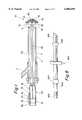
- FIG. 1is a longitudinal view of a blood filter device according to one embodiment
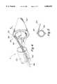
- FIG. 2is a longitudinal view of a blood filter device according to another embodiment, and in which the device is unsheathed and in an actuation position;
- FIG. 3is a longitudinal view of a blood filter device depicted in FIG. 2, and in which the device is unsheathed and in a release position;
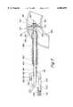
- FIG. 4is a longitudinal view of a blood filter device according to another embodiment;
- FIG. 5is a cross-sectional view through section line 5--5 of the device depicted in FIG. 4, showing the connection between the balloon and mesh of the device;
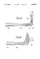
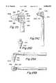
- FIG. 7is a longitudinal view of the blood filter device depicted in FIG. 6, showing the filter deployed after insertion of the cannula into the aorta;
- FIG. 8is a longitudinal view of a flexible arterial cannula showing standard features which are presently commercially available;
- FIG. 9is a longitudinal view of a blood filter device according to another embodiment, showing the filter deployed after insertion of the cannula into the aorta;
- FIG. 10is a longitudinal view of a blood filter device according to another embodiment.
- FIG. 10Ais a cross-sectional view through section line A--A of the blood filter device depicted in FIG. 10.
- FIG. 11is longitudinal view of a cannula with associated filter and distal flow diffuser.
- FIG. 11ais a detail of the flow diffuser of FIG. 11.
- FIG. 12is a longitudinal view of a cannula with associated filter and distal flow diffuser.
- FIG. 13is a longitudinal view of a cannula with associated filter and proximal flow diffuser.
- FIG. 14is a longitudinal view of a cannula with associated filter and a proximal flow diffuser.
- FIG. 17shows detail of an unrolled filter sleeve and accompanying control lines.
- FIG. 18is a three-dimensional drawing of a cannula with associated filter with a filter sleeve in the rolled up position.
- FIG. 19is a longitudinal view of a cannula with associated filter including a sleeve deployable by virtue of a pulley mechanism.
- FIG. 20is a longitudinal view of a cannula with associated filter wherein the cannula has a collapsible section which can accommodate the thickness of the filter.
- FIG. 21is a longitudinal view of a balloon aortic elastic cannula wherein the cannula's outer diameter and filter profile are reduced by introduction of a stylet in the cannula's central lumen.
- FIG. 22is a longitudinal view of the balloon aortic elastic cannula of FIG. 21 wherein the stylet has been withdrawn.
- FIG. 23is a longitudinal view of a cannula wherein the expander is proximal to the collapsible portion of the distal cannula.
- FIGS. 25 and 25cdepict a cannula wherein the filter has an elasticmeric compliant edge which conforms to vessel irregularities.
- FIGS. 25a, 25b, and 25dshow other views of the cannula depicted in FIG. 25c.
- FIG. 26shows a cannula having an open-ended sleeve disposed within the aorta.
- FIG. 1shows one embodiment of the blood filter device for use herein.
- the blood filter device 10comprises an insertion tube 20, an umbrella frame 30, and an end plate 60, an activation tube 50, a mesh 40, an adjustment device 70, and a handle 80.
- the device 10is introduced into a vessel through a main port 7 of a cannula 5, and blood or other surgical equipment may be introduced into the main port 7 of the cannula 5 through a side port 3.
- the cannula 5 and the device 10will not interfere with placement of equipment which may be used during a surgical procedure.
- the umbrella frame 30comprises a plurality of arms 32 (some of which are not shown), which may include 3 arms, more preferably 4 arms, more preferably 5 arms, more preferably 6 arms, more preferably 7 arms, more preferably 8 arms, more preferably 9 arms, and most preferably 10 arms.
- the armsare sonically welded to a socket 34, which in turn is adhesive bonded to the insertion tube 20 which is dimensioned to fit within the main port 7 of the cannula 5 without unnecessarily impeding blood flow.
- the socket 34may be connected to the insertion tube 20 by welding or epoxy.
- the insertion tube 20is made of commercially available material such as polyvinyl, clear PVC, polyurethane, or other plastics.
- the arms 32 of the umbrella frame 30are made of plastic or thin gage metal. Because of the flexibility of this material, the arms 32 bend without the need for extra parts such as hinges. This simplifies assembly and reduces the chances of misassembly.
- Each of the arms 32is provided with an undercut to facilitate bending.
- the arms 32may be made of a material having a shape memory characteristic, causing the arms to bend in the absence of external forces.
- a silicone materialmay be attached to the arms at the point at which they bend to act as a shock absorber.
- the armsmay be coated with a hydrophilic coating or other shock absorbing material.
- the frameincludes eight arms in one preferred embodiment, it is also contemplated that the umbrella frame may comprise more or less than eight arms.
- the end plate 60comprises a one-piece injection molded component, made of plastics or metal.
- the end plate 60is substantially O-shaped with a radius r and indent in the center of the O-shape.
- the eight arms 32 of the umbrella frame 30are sonic welded or bonded to the end plate 60 at eight arm junctures 61 spaced in 45 degree increments along a circumference of a circle defined by radius less than r.
- the activation tube 50is welded or attached with epoxy to the indent 62.
- the activation tube 50extends from the end plate 60, through the insertion tube 20, to the adjustment device 70 housed in the handle 80 as shown in FIG. 1.
- the adjustment device 70is a linear actuation device, comprising a thumb switch 72 which is attached to a guide frame 74 which in turn is attached to the activation tube 50 via a bond joint.
- Thumb switch 72comprises a base 76 and a ratchet arm 78 which moves along a ratchet slot 82 along the top of the handle 80, locking in predetermined intervals in a manner known in the art. Sliding the thumb switch 72 away from the distal end 2 of the cannula 5 retracts the activation tube 50, which in turn draws the end plate 60 toward the handle 80.
- the linear actuation devicemust include a locking mechanism which, when locked, maintains the arms 32 in a straight position and which, when released, allows the arms 32 of the umbrella frame 30 to bend.
- linear actuation devicesknown in the art also may be incorporated into the present invention such as, but not limited to, a friction fit slot device with a nub on the end, a device which incorporates hydraulic pressure or an electromechanical device with a motor.
- the meshTo filter blood effectively, i.e., to entrap embolic material, without unduly disrupting blood flow, the mesh must have the appropriate physical characteristics, including area (A M ), thread diameter (D T ), and pore size ( P S ).
- the mesh 40In the aorta, the mesh 40 must permit flow rates as high as 3 L/min or more, more preferably 3.5 L/min or more, more preferably 4 L/min or more, more preferably 4.5 L/min or more, more preferably 5 L/min or more preferably 5.5 L/min or more, and most preferably 6 L/min or more at pre-arterial pressures of around 120 mm Hg or less.
- aortic embolic loadhas been found to range from 0.57 cc to 11.2 cc, with a mean of 3.7 cc, and an estimated cerebral embolic load has been found to range from 60 to 510 mm 3 , with a mean of 276 mm 3 .
- the benefit of reducing the size of the interactive bubblesis twofold.
- the area of the mesh required for the device 10is calculated in the following manner.
- the number of pores N P in the meshis calculated as a function of thread diameter, pore size, flow rate, upstream pressure and downstream pressure. This is done using Bernoulli's equation for flow in a tube with an obstruction: ##EQU1##
- KK entry +K exit ;
- fis given as ##EQU3## where Re is the Reynold's number and the Reynold's number is given by the following equation: ##EQU4## where ⁇ is the kinematic viscosity of the fluid and A h is the area of one hole in the mesh given by S P *S P .
- the area of the meshis calculated as a function of the number of pores, thread diameter and pore size using the following equation:
- mesh areais 3-10 in 2 , more preferably 4-9 in 2 , more preferably 5-8 in 2 , more preferably 6-8 in 2 , most preferably 7-8 in 2 ;
- mesh thicknessis 20-280 ⁇ m, more preferably 23-240 ⁇ m, more preferably 26-200 ⁇ m, more preferably 29-160 ⁇ m, more preferably 32-120 ⁇ m, more preferably 36-90 ⁇ m, more preferably 40-60 ⁇ m; thread diameter is 10-145 ⁇ m, more preferably 12-125 ⁇ m, more preferably 14-105 ⁇ m, more preferably 16-85 ⁇ m, 85 ⁇ m, more preferably 20-40 ⁇ m; and pore size is 50-300 ⁇ m, more preferably 57-285 ⁇ m, more preferably 64-270 ⁇ m, more preferably 71-255 ⁇ m, more preferably 78-240 ⁇ m, more preferably
- mesh areais 3-8 in 2 , mesh thickness is 36-90 ⁇ m, thread diameter is 16-85 ⁇ m, and pore size is 103-165 ⁇ m.
- mesh areais 3-5 in 2 , mesh thickness is 40-60 ⁇ m, thread diameter is 20-40 ⁇ m, and pore size is 120-150 ⁇ m.
- Fluid flowmay be observed from a reservoir through a pipe attached to the bottom of the reservoir with the mesh placed over the mouth of the pipe through which the fluid exits the pipe.
- a mixture of glycerin and watermay be used to simulate blood.
- Fluid height (h)is the length of the pipe in addition to the depth of the fluid in the reservoir, and it is given by the following equation: ##EQU7## where ⁇ is given by the density of the glycerin-water mixture, and g is given by the gravity constant (9.8 ms 2 ).
- V 1is given by the following equation:
- Reynold's number (Re)is given by the following equation: ##EQU9## where ⁇ and ⁇ are, respectively, the density and kinematic viscosity of the glycerin-water mixture.
- suitable meshcan be found among standard meshes known in the art.
- polyurethane meshesmay be used, such as Saati and Tetko meshes. These are available in sheet form and can be easily cut and formed into a desired shape.
- the meshis sonic welded into a cone shape.
- Other meshes known in the art, which have the desired physical characteristics,are also suitable.
- the mesh 40is sonic welded or adhesive bonded to the arms 32 of the umbrella frame 30 from the end plate 60 to a point on each arm 32 between the end plate 60 and the socket 34 as shown in FIG. 1. This is the optimal placement of the Mesh 40 when the device 10 is inserted into the vessel in the direction of the blood flow.
- the device 10may be inserted in a direction opposite the blood flow.
- the mesh 40would be attached to the arms 32 of the umbrella frame 30 from the socket 34 to a point on each arm 32 between the socket 34 and the end plate 60.
- Anticoagulantssuch as heparin and heparinoids, may be applied to the mesh 40 to reduce the chances of blood clotting on the mesh 40.
- Anticoagulants other than heparinoidsalso may be used.
- the anticoagulantmay be painted or sprayed onto the mesh.
- a chemical dip comprising the anticoagulantalso may be used.
- Other methods known in the art for applying chemicals to meshmay be used.
- the device 10may be used in the following manner.
- a cannula 5is introduced into the vessel through an incision made in the vessel wall, and the cannula 5 is then sutured to the vessel wall.
- the cannula 5is preferably size 22-25 French (outer diameter).
- the blood filter device 10is then inserted into the vessel through the cannula 5.
- the blood filter device 10is maintained in a release position in which the arms 32 of the umbrella frame 30 are straight and the mesh 40 is closed. (See FIG. 3.)
- the surgeonslides the thumb switch 72 of the adjustment device 70 along the ratchet slot 82, away from the distal end 2 of the cannula 5, until an appropriate actuation position is achieved or until the mesh 40 is opened to its maximum size. (See FIG. 2.)
- the arms 32may bend to varying degrees in a plurality of actuation positions, and the appropriate actuation position depends on the cross-sectional dimension of the blood vessel. During filtration, a user may gently palpate the outside of the blood vessel to feel points of contact between the vessel wall and the device 10. This enables the user to determine the appropriate actuation position and the location of the device within the vessel.
- the userslides the thumb switch 72 toward the distal end 2 of the cannula 5, thereby effecting the release position, in which the arms 32 of the umbrella frame 30 straighten and the mesh 40 closes around the captured emboli.
- the handle 80may be additionally provided with a marker band which matches up with a corresponding marker band on the thumb switch 72 when the device 10 is in the release position.
- the device 10is pulled back into the cannula 5, and then cannula 5 and the device 10, along with the captured emboli, are removed from the body.
- a blood filter deviceis provided as illustrated in FIGS. 2 and 3.
- the device 10comprises an introducer 103, a cannula 105, having a distal end 111, a sheath 120, an umbrella frame 130, an annular mesh 140, a movable ring 150, a fixed ring 160, guidewires 170, and a clam-shell handle 180.
- the introducer 103comprises a cylinder 107 and an adjustable suture ring 109.
- the cylinder 107 of the introducer 103is made to fit around the sheath 120, which slides over the cannula 105 and the guidewires 170.
- the umbrella frame 130is substantially similar to the umbrella frame 30 depicted in FIG. 1.
- the umbrella frame 130comprises a plurality of arms 132 (some of which are not shown) as discussed above with reference to FIG. 1, which arms are connected at one end (of each arm 132) to the fixed ring 160 and at the other end (of each arm 132) to the movable ring 150.
- the fixed ring 160is firmly secured to the cannula 105.
- Each guidewire 170is firmly secured at one end to the movable ring 150m, which slides along the outer surface of the cannula 105, and at the other end to the clamshell handle 180, which is a linear actuation device known in the art.
- the mesh 140must entrap embolic material without unduly disrupting blood flow. This mesh 140 also may be found among standard meshes known in the art. The same analysis used to select and test the mesh 40 of the first preferred embodiment may be used to select the mesh 140.
- the device 10is used in the following manner.
- the device 10is inserted into the blood vessel.
- the sheath 120is retracted until it exposes the umbrella frame 130.
- a usereffects the actuation position by pushing the movable ring 150 toward the fixed ring 160 via the clam-shell handle 180 and the guidewires 170 as shown in FIG. 2.
- the arms 132 of the umbrella frame 130are bent and the annular mesh 140 is open and ready to capture foreign matter in the blood.
- the userIn order to remove the blood filter 10 from the body, the user first pulls the movable ring 150 away from the fixed ring 160 via the clamshell handle 180 and the guidewires 170. This causes the arms 132 of the umbrella frame 130 to straighten and the annular mesh 140 to close, trapping the emboli against the cannula 105. The user then removes the blood filter device 10 from the body along with the captured emboli. Alternatively, the user may first slide the sheath 120 back over the cannula 105, and then remove the device 10 from the body along with the captured emboli.
- a second meshmay be placed over the distal end 111 of the cannula 105 or within the cannula 105 so that blood flowing into the body from an extracorporeal source is also filtered.
- a single meshmay be used which is configured such that it covers the distal end 111 of the cannula 105.
- An advantage of the embodiment depicted in FIG. 2is that it does not require a cannula with a separate port for the introduction of blood or a surgical equipment.
- FIG. 4shows another embodiment of the blood filter device disclosed herein.
- the blood filter device 10comprises a mesh 220, an inflatable balloon 230, a collar 240, a plurality of tie lines 250, and an actuation assembly 260.
- the mesh 220is attached to the balloon 230 via the collar 240.
- the device 10is positioned and maintained in a blood vessel via the plurality of tie lines 250.
- Manipulation of actuation assembly 260inflates and deflates the balloon 230 and controls the degree of inflation and deflation. Inflation of the balloon 230 opens the mesh 220, and deflation of the balloon 230 allows the mesh 220 to close.
- Mesh 220found among standard meshes as in the first two embodiments, should cover substantially all of the cross-sectional area of a vessel so that blood flowing in the vessel must pass through the mesh 220. In this way, foreign matter in blood within the vessel is entrapped by the mesh 220.
- the mesh 220is generally cone-shaped. However, the shape of the mesh 220 may be modified to assume any shape as long as blood flowing in the vessel passes through the mesh 220.
- inflatable balloon 230is attached to the mesh 220 via the collar 240.
- the balloon 230is made of two pieces of a flexible, slightly porous material such as urethane or polyethylene terephalate (PET), each piece having an outer diameter and an inner diameter. These pieces are welded together at both the outer and inner diameters in a manner known in the art.
- the balloon 230also has a valve 268 and a valve stem 266 located between the outer diameter and the inner diameter of the balloon 230.
- Material used for the balloon 230must be capable of inflation and deflation. It also must be sufficiently flexible to conform to the walls of a vessel regardless of possible irregularities in the walls, such as may be caused by plaque or other materials adhering to the walls. Material used for the balloon 230 also must be sufficiently flexible to allow the balloon 230 to fold up within a cannula 205. Exemplary materials include elastomeric and certain non-elastomeric balloons.
- a fluid or a gasis introduced into the balloon 230 through the valve 268.
- the fluid or gasis removed from the balloon 230 through the valve 268.
- Fluidssuch as saline may be used, and gases such as inert gases may be used with this invention. Any fluid or gas may be used as long as it does not harm the patient if released into the bloodstream.
- the saline or other suitable inflation materialis typically stored in a reservoir outside the body, which is capable of fluid communication with the balloon 230 through a tube 264.
- the dimensions of the balloon 230may be adjusted in alternative embodiments adapted for use in vessels other than the aorta. Alternatively, expandable members other than a balloon also may be used with this invention.
- the collar 240is attached to the outer diameter of the balloon 230 and is a generally circular piece of plastic.
- Other materialssuch as silicone or high density polyethylene may be used. This material should be rigid enough to withstand flow conditions in blood vessels, yet flexible enough to expand as the balloon 230 is inflated and to fold up as the balloon 230 is deflated and stored within the cannula 205.
- the collar 240has both an inner and outer diameter, and the outer diameter is bent slightly outward. As shown in FIG. 5, the collar 240 is attached to the outer diameter of the balloon 230 by welding, adhesive or other attachment means known in the art.
- the mesh 220is adhesive bonded to the collar 240. Alternatively, the mesh 220 may be connected to the collar 240 by welding, epoxy, or other suitable adhesive means.
- Actuation of the device 10is accomplished by the actuation assembly 260, which inflates and deflates the balloon 230 by introducing into and removing from the balloon 230 the fluid or gas.
- the actuation assembly 260also controls the degree to which the mesh is opened within the blood vessel.
- the actuation assembly 260may be used to adjust the fit of the device 10 within the vessel during filtration or use of the device 10.
- one embodiment of the devicemay be suitable for a variety of vessel sizes.
- Actuation assembly 260comprises an inflation catheter 262 and the tube 264 which is connected to the valve stem 266.
- the inflation catheter 262is preferably 9 F. O.D. and is marked in cubic centimeter increments in order to monitor the degree to which the balloon 230 is inflated.
- the tube 264is preferably size 12 Fr. O.D. and 7.2 Fr. I.D.
- a plurality of tie lines 250which may include three tie lines, four tie lines, or more than four tie lines, position and maintain the device 10 in place in the bloodstream.
- the tie lines 250are made of wire and are threaded through the balloon 230 at points equally spaced along the inner diameter of the balloon, e.g., for four tie lines the four points are space 90 degrees apart along the inner diameter of the balloon 230.
- the tie lines 250may be made of other materials having sufficient stiffness to push and pull the balloon 230 out of and into the cannula 205 and to maintain the device 10 within the blood vessel.
- All components of this deviceshould be composed of materials suitable for insertion into the body. Additionally, sizes of all components are determined by dimensional parameters of the vessels in which the devices are intended to be used. These parameters are known by those skilled in the art.
- An advantage of all embodiments disclosed hereinis that the blood filter will capture emboli which may result from the incision through which the blood filter is inserted.
- the devices of the present inventionare particularly suited for use in methods of the present invention. However, other devices may be adapted for use in accordance with the methods of the present invention.
- the methods of the present inventiongenerally include the following steps: introducing a blood filter device into a blood vessel of a patient to entrap embolic matter or foreign matter in the blood; and removing the mesh and the entrapped foreign matter from the blood vessel.
- the blood filter devicealso may be adjusted if this is necessary during the course of filtration.
- visualization techniquesis also contemplated in order to determine which patients require filtration (identify risk factors), where to effectively position a blood filter device to maximize effectiveness, when to adjust the device if adjustment is necessary, when to actuate the device and appropriate regions for performing any procedures required on a patient's blood vessel.
- the blood filter device depicted in FIGS. 4 and 5is introduced into a patient's blood vessel.
- an incisionis first made in a vessel of a patient, and, with reference to FIG. 4, cannula 205 is introduced into the incision in the direction of blood flow.
- the device 10is stored in a closed position in which the balloon is deflated and generally folded in upon itself and the mesh 220 is closed.
- the blood filter device 10is then pushed out through the cannula 205 into the vessel by pushing the tie lines 250 in the direction of blood flow.
- the actuation assembly 260inflates the balloon until the balloon 230 opens the mesh 220 within the vessel to cover substantially all of the cross-sectional area of the vessel such that blood flowing through the vessel flows through the mesh 220. As the blood flows through the mesh 220, foreign matter is entrapped by the mesh.
- the device 10When the filter is no longer needed, the device 10 is removed from the vessel along with the entrapped foreign matter.
- the balloon 230is deflated, and the tie lines 250 are pulled toward the cannula opposite the direction of the blood flow.
- the balloon 230As the balloon 230 is pulled into the cannula 205, the balloon 230 folds in upon itself, and the mesh 220 closes around the entrapped foreign matter.
- the cannula 205may be configured to further accommodate entry of the balloon 230, the mesh 220, and the entrapped foreign matter into the cannula 205 without disturbing blood flow.
- the end of the cannula placed within the vesselmay be very slightly flared.
- a visualization techniquesuch as TCD is used to determine when to actuate a blood filter device.
- TCDa visualization technique
- a meshmay be opened within a vessel downstream of the aorta during these procedures and closed when embolization resulting from these procedures has ceased. Closing the mesh when filtration is not required helps to minimize obstruction of the blood flow.
- a visualization techniqueis used to monitor emboli entering cerebral circulation to evaluate the effectiveness of a blood filter device in trapping emboli. Also, a visualization technique is useful to positioning a device within a vessel so that it operates at optimum efficiency. For example, a user may adjust the position of the device if TCD monitoring indicates emboli are freely entering the cerebral circulation. In addition, a user may adjust a mesh of a blood filter device to ensure that substantially all of the blood flowing in the vessel passes through the mesh.
- a visualization techniquesuch as TEE and epicardial aortic ultrasonography, is used to identify those patients requiring blood filtration according to the present invention.
- these visualization techniquesmay be used to identify patients who are likely to experience embolization due to the presence of mobile plaque. These techniques may be used before the patient undergoes any type of procedure which will affect a blood vessel in which mobile plaque is located.
- visualization techniquesmay be used to select appropriate sites on a blood vessel to perform certain procedures to eliminate or reduce the occurrence of embolization.
- the aortais both clamped and cannulated. These procedures frequently dislodge atheromatous material already present on the walls of the aorta.
- a usermay clamp or cannulate a section of the aorta which contains the least amount of atheromatous material, as identified by TEE, epicardial aortic ultrasonography or other visualization technique.
- Procedures other than incising and clampingalso tend to dislodge atheromatous material from the walls of vessels. These procedures include, but are not limited to, dilatation, angioplasty, and atherectomy.
- Visualization techniquesalso may be used to select appropriate sites for filtering blood. Once atheromatous material is located within a vessel, a blood filter device may be placed downstream of that location.
- Visualization techniquesare also useful in ascertaining the contours of a blood vessel affected by surgical procedure to assess a variety of risk of embolization factors, and to locate appropriate sections of a vessel for performing certain procedures. Any suitable visualization device may be used to evaluate the efficacy of a device, such as those disclosed herein, in trapping emboli.
- a cannula with associated filteris provided as depicted in FIGS. 6 and 7.
- the deviceincludes a pressurizing cannula 300 having proximal region 301, distal region 302, and an intermediate region which connects the proximal and distal regions.
- the pressurizing cannula 300is typically a rigid or semi-rigid, preferably transparent tube having a first substantially cylindrical lumen 303 which extends from the proximal region to the distal region and is shaped to receive blood supply cannula 350.
- the pressurizing cannula 300further includes at its proximal region luer fittings 304 and 305 which are shaped to receive a cap or septum 306 and a syringe 307 filled with saline or gas and having a locking mechanism 308 (FIG. 7) for locking the barrel 309 and plunger 310 in a fixed position.
- the pressurizing cannula 300typically has a dual lumen to effect pressurization of the inflation seal (discussed below).
- luer 305is connected to passage 311 which is in fluid communication with a second lumen 312 which extends from the proximal to the distal end of pressurizing cannula 300.
- luer 304is connected to passage 313 which is in fluid communication with a third lumen 314 which extends from the proximal to the distal end of pressurizing cannula 300.
- the pressurizing cannula 300includes a blood filtration assembly 315 which is shown in greater detail in FIG. 7.
- FIG. 8depicts a standard flexible arterial cannula 400 which is commercially available from Sarns 3M (Ann Arbor, Mich.). With reference to FIG. 8, the cannula will typically have a length of about 25 cm.
- the cannulaincludes a distal end region 401, a proximal end region 402, and an intermediate region disposed therebetween.
- Distal end region 401has an outer diameter of about 8 mm, and a sealing ring 403 having an enlarged diameter of about 13 mm, a width of about 5 mm, and being disposed about 25 mm from the distal tip of cannula 400.
- Sealing ring 403functions as an anchor point against the inside of an aortic incision so that cannula 400 does not slide from the aorta during a procedure.
- Proximal end region 402includes a connector 404 which joins the cannula to the blood machine.
- the cannulaAt its proximal tip, the cannula includes a tapered joint 405 which connects and locks the cannula to a bypass-oxygenator machine.
- blood supply cannula 350may have certain features in common with the standard cannula 400 depicted in FIG. 8.
- Blood supply cannula 350 for use hereinis a substantially cylindrical, semi-rigid, and preferably transparent tube which includes a rib 351 disposed about the circumference at a distal region thereof.
- the blood cannulais slidable within the pressurizing cannula, and in the proximal region, the blood cannula 350 may be angled to adopt a shape which does not interfere with syringe 307.
- the blood cannulawill typically include a fitting or molded joint 352 which is adapted for coupling to a bypass-oxygenator system.
- Blood cannula 350is adapted to carry blood to the aorta from the bypass-oxygenator system.
- the pressurizing cannulamay also include an inserting and retracting handle 380 comprising a substantially cylindrical tube disposed about the intermediate region of pressurizing cannula 300.
- Handle 380will generally include a rigid or semi-rigid, preferably transparent tube with molded hand grip to facilitate holding and inserting.
- handle 380is slidable relative to the pressurizing cannula 300, and may include a sealing member 381 comprising a rubber washer or O-ring mounted in a proximal region of the handle and disposed between handle 380 and pressurizing cannula 300 to prevent leakage of blood therebetween.
- Handle 380may include corrugation ribs 382 and its proximal and intermediate regions, and a substantially flat or level collar insertion region 383 adapted to fit tightly against vessel material at an aortic incision.
- the collar insertion region 383will include a sealing ring or rib (not shown), having a width of about 5 mm and an outer diameter of about 13 mm, which serves as an anchor against the aorta to prevent the cannula assembly from slipping out during a surgical procedure.
- a "purse string" sutureis generally tied around the circumference of the aortic incision, and this string will be tightened around the ring in collar region 383 to prevent slippage of the cannula assembly.
- Handle 380may also include an enlarged end region 384 which encloses the blood filtration assembly 315 as depicted before insertion in FIG. 6.
- This housing enclosure 384is a particularly preferred component because it prevents inadvertent deployment of the blood filtration assembly, and it provides a smooth outer surface to the cannula which facilitates entry through an incision in the aorta without tearing the aorta. In the absence of such housing enclosure, the balloon and filter are liable to scrape against the inner wall of a vessel, and thereby damage or rupture the vessel.
- handle 380may include inverted cuff 385 which bears against rib 351 of blood cannula 350 to form a seal when the filtration assembly 315 is enclosed in handle 380.
- the distal region of pressurizing cannula 300is shown with blood filtration assembly 315 deployed in the ascending region of a human aorta 399.
- Handle 380has been moved proximally to expose filter assembly 315.
- the distal region of pressurizing cannula 300includes a plurality of spokes or holding strings 316 made from DacronTM or other suitable material. Holding strings 316 connect the distal region of the pressurizing cannula 300 to an inflation seal 317 which comprises a continuous ring of preferably thin tubing attached to filter mesh 318 on its outer side.
- Filter mesh 318is bonded at its distal end around the circumference of blood cannula 350, preferably at a cross-sectional position which closely abuts rib 351.
- Inflation seal 317may be constructed from elastomeric or non-elastomeric tubular material which encloses donut-shaped chamber 319. When deployed, the inflation seal will expand to a diameter which fits tightly against the lumen of aorta 399. The inflation seal will thus be capable of expansion to an outer diameter of at least 2 cm, more preferably at least 2.5 cm, more preferably at least 3 cm, more preferably at least 3.5 cm, more preferably at least 4 cm, more preferably at least 4.5 cm. These diameter ranges will accommodate both pediatric use and adult use.
- the inflation sealis typically a continuous ring of very thin tubing attached to the mesh filter on one side and to the pressurizing cannula by holding strings on the other side.
- the inflation sealshould be able to maintain an internal pressure in chamber 319, without bursting, of greater than 55 mm Hg, more preferably greater than 60 mm Hg, more preferably greater than 70 mm Hg, more preferably greater than 80 mm Hg, more preferably greater than 90 mm Hg, more preferably greater than 100 mm Hg, more preferably greater than 110 mm Hg, more preferably greater than 120 mm Hg, more preferably greater than 130 mm Hg, more preferably greater than 140 mm Hg, more preferably greater than 150 mm Hg.
- the internal pressure neededwill depend on the pressure maintained in the aorta against the mesh.
- the aortic pressureis 55 mm Hg
- the pressure in the inflation sealmust be greater than 55 mm Hg to prevent leakage around the seal.
- the aortic pressurewill be at least 75 mm Hg because this level of pressure is needed to ensure adequate brain perfusion. It will be recognized that such inflation seal pressures are much higher than the maximum level that can be used in the pulmonary venous system because the veins and arteries therein will typically hold no more than about 40-50 mm Hg, or at most 60 mm Hg without rupture.
- Chamber 319is in fluid communication with a first tubular passage 320 and a second tubular passage 321 which permit chamber 319 to be inflated with gas, or preferably a fluid such as saline.
- Passage 320is in fluid communication with second lumen 312 of pressurizing cannula 300, while passage 321 is in fluid communication with third lumen 314 of pressurizing cannula 300.
- Passage 320 and 321thereby interconnect chamber 319 with the second and third lumens 312 and 314, respectively, of pressurizing cannula 300.
- inflation seal 317will include a septum 322 which blocks the movement of fluid in one direction around chamber 319. If septum 322 is positioned in close proximity to the fluid entry port, then the injection of fluid will push all gas in chamber 319 around inflation seal 317 and out through passage 321. In one embodiment, the entry port and the exit port are positioned in close proximity with septum 322 disposed between the entry and exit port. In this case, injection of fluid will force virtually all gas out of inflation seal 317.
- Filter mesh 318is bonded at its proximal end to inflation seal 317 and at its distal end to blood cannula 350, optionally at the proximal or distal edge of rib 351.
- Mesh 318can be made of a material which is reinforced or non-reinforced.
- Mesh 318when expanded as shown in FIG. 7, may assume a substantially conical shape with a truncated distal region.
- the meshshould be formed of a material having a pore size which obstructs objects 5 mm in size or less, more preferably 3 mm in size, more preferably less than 3 mm, more preferably less than 2.75 mm, more preferably less than 2.5 mm, more preferably less than 2.25 mm, more preferably less than 2 mm, more preferably less than 1.5 mm, more preferably less than 1 mm, more preferably less than 0.75 mm, more preferably less than 0.5 mm, more preferably less than 0.25 mm, more preferably less than 0.1 mm, more preferably less than 0.075 mm, more preferably less than 0.05 mm, more preferably less than 0.025 mm, more preferably 0.02 mm, and down to sizes just larger than a red blood cell.
- the necessary pore sizeis a function of blood throughput, surface area of the mesh, and the pressure on the proximal and distal side of the mesh. For example, if a throughput of 5-6 L/min. is desired at a cross-section of the aorta having a diameter of 40 mm, and a pressure of 120 mm Hg will be applied to the proximal side of the mesh to obtain a distal pressure of 80 mm Hg, then a pore size of about ⁇ 50 ⁇ m is needed.
- the same throughputis needed, but the artery cross-section has a diameter of only 30 mm.
- the proximal pressureis typically 40-60 mm Hg, while the distal pressure is about 20 mm Hg.
- a much larger pore sizeis needed to maintain blood flow. If pore sizes as disclosed herein for the aorta were used in the pulmonary artery, the blood throughput would be insufficient to maintain blood oxygenation, and the patient would suffer right ventricular overload because of pulmonary artery hypertension.
- the cannulamust have an inner diameter which allows blood throughput at a mean flow rate of at least 3.0 L/min., more preferably 3.5 L/min., more preferably 4 L/min., more preferably at least 4.5 L/min., more preferably at least 5 L/min., and more.
- flow ratecan vary intermittently down to as low as 0.5 L/min.
- the inner diameter of blood supply cannula 350will typically be at least 9 F (3.0 mm), more preferably 10 F, more preferably 11 F, more preferably 12 F (4 mm), more preferably 13 F, more preferably 14 F, more preferably 15 F (5 mm), and greater.
- the outer diameter of blood cannula 350is approximately 8 mm.
- the pressurizing cannula 300 and handle at the collar region 383have outer diameters of approximately 10.5 mm and 13.0 mm, respectively.
- the cannula with associated filterhas syringe 307 which is removed, and aseptically filled with a saline solution.
- the syringeis then attached to pressurizing cannula 300, and cap 306 is removed.
- Salineis injected until saline exits from luer 304, thereby purging substantially all gas from the inflation seal and dual lumen system of pressurizing cannula 300.
- Cap 306is then replaced and secured to the pressurizing cannula 300.
- Cardiac surgerycan then be conducted in accordance with procedures which employ standard cannula insertion, as known in the art, and discussed more fully herein.
- the mesh 318 and inflation seal 317are enclosed under handle 380 at the enlarged end, just beyond the distal tip of pressurizing cannula 300.
- the cannulais introduced into the aorta, preferably the ascending aorta, of a patient through an incision, and the incision may be tightened about the cannula by use of a "purse string" suture. Cardiopulmonary bypass occurs through blood cannula 350.
- the filterWith the cannula in place, the filter is ready for deployment.
- the surgeongrips the handle, and the blood cannula 350 and pressurizing cannula 300 are pushed forward. This movement breaks the seal at the tip of the handle and allows the blood cannula and pressurizing cannula to thrust forward, thereby releasing the filter.
- the plunger of the syringeis then depressed within the barrel to expand the inflation seal.
- the inflation sealexpands to ensure contact with the inside of the aorta at all points along the circumference of the lumen.
- the syringeis then locked in place to prevent inflation or depressurization of the inflation seal during use.
- the aortais then cross-clamped at a region between the heart and the cannula incision. Embolic material dislodged from the aorta is caught and trapped by filter mesh 318.
- the bypass-oxygenator systemis then started to achieve cardiopulmonary bypass through blood cannula 350. Cardiac surgery is then performed while the filter and inflation seal are maintained in place for a number of hours, typically 8 hours or less, more typically 7 hours or less, more typically 6 hours or less, more typically 5 hours or less, more typically 4 hours or less, more typically 3 hours or less, and more typically 2 hours or less.
- the filteris depressurized and removed from the ascending aorta.
- the syringe lockis released and, while holding handle 380, the pressurizing cannula is drawn back. This will cause release of saline from inflation seal 317, and will retrieve the filter mesh, inflation seal, and pressurizing cannula back into and under the handle, as it was configured before deployment.
- embolic material collected in the filteris also trapped under the handle at its enlarged segment.
- the inflation sealmay be deflated before pull-back of the pressurizing cannula by operating the syringe to withdraw saline from the inflation seal.
- a cannulais provided as depicted in FIGS. 6 and 7 with a continuous filter mesh as shown in FIG. 4 which extends beyond and over the lumen of the blood cannula so that blood from the cannula passes through the mesh before circulating within the patient.
- the devicemay include a pressurizing cannula 300, blood cannula 350, inflation seal 317 and mesh 318.
- the devicemay optionally include a handle 380 and an inflation system as described above with reference to FIGS. 6 and 7.
- the inflation systemmay be carried by either the pressurizing cannula or the blood cannula.
- the blood cannula and pressurizing cannulawill be integrally combined into a single unitary component, and the inflation system may be carried either within or on the outside of the blood cannula. It will be understood that FIG. 9 shares many features in common with FIGS. 6 and 7, and the numbering of apparatus components has been duplicated so that appropriate description can be found with reference to FIGS. 6 and 7.
- a cannulais provided with an inflatable loading balloon as depicted in FIG. 10.
- the deviceincludes cannula 421 having pressurizing lumen 422 which extends from the proximal to the distal end.
- the cannulais equipped with an inflatable loading balloon 423 which, when inflated, exerts a radial outward force on stiffening wire ribs 424.
- the ribssupport filtration mesh 425 which extends from the surface of the cannula at one edge to inflation seal 426 at another edge.
- a plurality of retrieving strings 427are optionally provided which are attached at another end (not shown) to the plunger of the pressurizing syringe and therefore can be activated (advanced and withdrawn) by the motion of the pressurizing syringe which operates at the proximal end of cannula 421.
- the stringsmay be attached at the proximal end to a ring or slide which can be drawn to pull back, or advanced to let out the strings.
- FIG. 10Ashows a cross-sectional view of aorta 399 taken through section line A--A. It can be seen that the cannula is equipped with a plurality of stiffening wire ribs 424 which extend radially outward when loading balloon 423 is expanded.
- a cannula with associated filter and distal flow diffuseris provided in FIGS. 11 and 11a.
- the deviceincludes a pressurizing cannula 300, blood supply cannula 350 and a blood filtration assembly 315 comprising holding strings 316 inflation seal 317, filter mesh 318, chamber 319, tubular passages 320 and 321, and septum 322.
- the distal end of the blood supply cannulais closed with a cap 390 and the flow diffuser 395 is a rounded, hemispherical shape to facilitate the insertion of the distal end of the cannula 350 into the vessel.
- the flow diffuser 395tapers towards the proximal end of the cannula 350 starting from the cap 390.
- the shape of the diffuseris preferably conical, in order to avoid damaging the blood. However, other shapes, including pyramidal shapes, may be employed.
- a plurality of outlet openings 391are formed in the sidewall of the cannula 350 adjacent to its distal end.
- the openingsmay have an arched configuration, with the curved portion 392 of each arch oriented in the upstream direction.
- a preferred embodimenthas six openings.
- the total area of the openingsis greater than the area of the distal end opening of a conventional catheter of the same diameter.
- the length of the openings 391are also preferably greater than the length of the flow diffuser 395.
- a cannula with associated filter and flow diffuseris provided as depicted in FIGS. 12 and 12a.
- the distal end of the cannula 350contains a diffuser 396 with a helical configuration.
- the diffuser 396can be held in place within the cannula by the tapering configuration of the distal end of the cannula, by adhesives, by ultrasonic welding, or by some other suitable means.
- the diffuseris preferably formed from a flat rectangular member with a single one-hundred-eighty degree twist. In this embodiment, the distal end of the cannula is partially blocked. Additionally, any number of outlet openings 397 may be formed in the sidewall of the cannula.
- intra-cannula flow diffusers of FIG. 11 and FIG. 12may also be employed proximal to the filter by, for example, positioning the diffuser within the blood cannula of the device depicted in FIG. 9.
- Other variations and details of intra-lumen flow diffusersmay be found in Cosgrove et. al., Low Velocity Aortic Cannula, U.S. Pat. No. 5,354,288, which is incorporated by reference herein.
- a blood cannula with associated filter and flow diffuseris provided as in FIG. 13.
- the proximal end of a flow diffuser 702is connected to the distal end of the cannula 350 by a plurality of structural supports 704.
- the diffuser 702is preferably conical, although other shapes may be used.
- the distal end of the flow diffuser 702extends to the apex of the filter 706 by virtue of a linear shaft 708 said shaft running through the center of the expanded filter.
- the flow diffuser 702diffuses blood flow proximal to the filter 706.
- an arterial blood cannulais provided as in FIG. 14.
- the flow diffuser 802is contained within the distal end of the blood cannula 10.
- the diffuser 802is the helical diffuser shown in FIG. 12 and 12a.
- the flow diffuser 802can be held in place by the tapering configuration of the distal end of the cannula, by adhesives, by ultrasonic welding, or by any other suitable means.
- the distal end of the diffuser 802is attached to the apex of the filter 806 by virtue of a linear shaft 808 said shaft running through the center of the expanded filter.
- the shaftmay be any shape which will not traumatize blood components, and preferably comprises a rounded surface which tapers outward in the distal direction.
- the flow diffuseralso diffuses cannula blood flow proximal to the filter.
- the cannula 350optionally contains openings 803 in its distal end 804 to further diffuse the cannula blood.
- blood diffuser 802is contained within cannula 350 but is not connected to filter 806 said filter being supported as disclosed in FIG. 9.
- flow diffuserssuch as those of FIG. 11-14 can be used in any blood filter device having a blood supply cannula and associated filter, including the devices depicted in FIG. 2 and FIG. 3.
- the diffuser of FIG. 14may be employed inside a cannula having a distal filter, such as in FIG. 7, thus creating a blood filter device with two filters, one proximal to and one distal to the cannula opening.
- a blood filter device and associated filter 906include a generally cylindrical filter sleeve 908 disposed circumferentially about the distal end of cannula 10, and attached to four control lines 902a, 902b, 904a, and 904b. Proximal force on unroll control lines 904a and 904b unrolls filter sleeve 908 from its depicted position so as to capture the filter as shown in FIG. 16.
- the manner of unrolling the filter sleeveis analogous to the unrolling of a latex condom.
- the sleevemay be any shape, provided it both encases the device and rolls up in response to the control lines, in a preferred embodiment the sleeve has a circular cross-section.
- FIG. 15shows a cross-sectional cut-away of the sleeve.
- the full sleevenot depicted, is a continuous piece surrounding the cannula about a 360 degree axis.
- a circular condom-like sleeveis attached at the outer-diameter of the cannula along the arc of circle 910.
- the condom-like sleevehas a distal opening to permit exit of the cannula tip.
- a pair of control lines 902a and 904aenter a control lumen at points 928 and 929 respectively and run inside control lumen 922 adjacent the cannula lumen until exiting the control lumen at a proximal point on the cannula (not shown).
- control lines 902b and 904bsimilarly enter and exit a second control lumen 924 at points 926 and 927 respectively, said points located 180 degrees from the first lumen on the cannula's outer diameter.
- unroll control lines 904a and 904bare attached to sleeve 908 at points 914 and 916 respectively, said points located at the proximal end of the sleeve. Consequently, when sleeve 908 is rolled-up, as shown in FIG. 15, points 914 and 916 are rolled into the center of the nautilus-shaped lip of sleeve 908 while unroll control lines 904a and 904b are rolled-up along side the sleeve.
- roll-up control lines 902a and 902bare attached to the cannula at points 918 and 920 respectively. Points 918 and 920 are located on arc 910.
- the roll-up control lines 902a and 902brun from their respective points of attachment 918 and 920, along the exposed side of the rolled-up sleeve, and enter the control lumens 922 and 924 at points 926 and 928 respectively. After entering the control lumens, the roll-up lines proceed through the control lumens until exiting at points (not shown) proximally located on the cannula.
- FIG. 16shows the same blood filter device with blood cannula and associated filter as FIG. 15 but with the sleeve 908 fully unrolled and capturing filter 906.
- the unrolled sleeveprovides a compact, smooth profile for the device's introduction to and retraction from a vessel.
- the unroll lines 904a and 904b of FIG. 16are pulled in a proximal direction, away from the cannula tip. Consequently, points 914 and 916 are positioned at the proximal end of unrolled sleeve 908.
- the roll-up linesmay be pulled in a proximal direction, away from the cannula tip. Pulling the roll-up lines causes the sleeve 908 to roll-up until reaching the rolled-up state shown in FIG. 15.
- the sleeve 908is unrolled prior to insertion of the cannula in a vessel, rolled up during mesh deployment, and once again unrolled prior to cannula retraction.
- FIG. 17shows a cross-sectional detail of the sleeve 908 in the unrolled state, with emphasis on the points of attachment for the control lines.
- the sleevewhich is a continuous about 360 degrees (not shown) is directly connected to the two roll-up lines 902a and 902b at points 918 and 920 respectively.
- the roll-up linesare attached directly to the cannula at points neighboring 918 and 920 located immediately under the distal end of the sleeve. Pulling the roll-up lines in a proximal direction, as shown by the arrows in FIG. 17, causes the sleeve to roll-up like a condom.
- the sleeve materialshould be thin enough to avoid bunching and to provide smooth rolling in reaction to proximal force exerted by the roll-up lines.
- the sleeveis made of latex, with a thickness of between 3 and 14 thousandths of an inch.
- the sleeveis made of latex with a thickness of between 4 and 16 thousandths of an inch.
- the inventionmay also use silicone or another silastic, biocompatible material to construct the sleeve. Other materials as are known in the art may permit use of a sleeve with a thickness of less than 6 thousandths of an inch provided the material gives suitable assurances against breaking or tearing.
- FIG. 18is a three-dimensional depiction of the cannula 350, filter 906 and sleeve 908, with sleeve 908 in the rolled-up state.
- the filter 906is located distal to the cannula opening such that cannula output is filtered upon exiting the cannula.
- the filteris located proximal to the cannula opening such that cannula output is downstream of the filter.
- the cannula openingmay optionally have a planar diffuser 932.
- Filter 906is made of a mesh which is contiguous with a sealing skirt 930. With the exception of entrance point 933 both the roll-up and unroll lines enter and exit the cannula at points not shown.
- control linesattach to a control line actuating mechanism such as a capstan, ring or pulley (also not shown).
- a control line actuating mechanismsuch as a capstan, ring or pulley (also not shown).
- the structure adapted to open and close the filtermay be an umbrella frame (not shown), such as depicted in FIG. 1, or alternatively an inflation balloon (not shown), such as shown in FIG. 7 and FIG. 9.
- the FIG. 18 embodimentmay be used with any of the various means to actuate the structure as described herein.
- unroll control lines 904a and 904b in a proximal directioncauses the capture sleeve to roll out over the top of the filter. Subsequently pulling the roll-up control lines 902a and 902b in a proximal direction rolls-up the capture sleeve thereby permitting filter deployment.
- the unroll linesare oriented at an angle of 180 degrees from one another along the circumference of the filter (thus 904b not shown).
- the roll-up lines 902a and 902bare similarly oriented at an angle of 180 degrees from one another.
- this embodimentmay employ any number of control lines spaced at varying differences around the outer diameter of the filter sleeve.
- FIG. 19shows an alternative embodiment wherein one control ring 936 controls rolling and unrolling of the sleeve 934 with the assistance of a pulley mechanism.
- the control ring 936is movable in both the proximal and distal directions along the outer diameter of the cannula (not shown).
- Control ring 936is directly attached to unroll control lines 904a and 904b and attached to roll-up control lines 902a and 902b through pulley 934. Proximal movement of the control ring causes the sleeve 908 to unroll. Distal movement conversely causes sleeve 908 to roll up.
- the cannula 350contains a collapsible or deformable section 938 such that the cannula can accommodate the filter 906 and filter seal 907, as well as other filter components.
- the collapsible section 938is made out of an elastomeric material such as latex or silicone.
- the collapsible sectionis a double walled balloon.
- the sectionis made of a flexible material with built in memory such that the collapsible walls automatically return to their non-collapsed state when deployment force expands the filter means.
- the collapsing sectionbegins proximal to the filter seal 907 when the filter is in its collapsed state.
- the collapsing section 938begins just proximal to the site of the filter seal 907 and has a length equal to the length of the filter and filter seal.
- the collapsing sectionextends to the tip of the catheter from just proximal to the filter seal.
- the deformable sectioncollapses radially inward when the filtration assembly is closed in order to produce a low-profile distal end to the cannula.
- a portion of the radial volume of the cannulais occupied by the filtration assembly when the filtration assembly is deployed; however, the blood flowing through the cannula subsequently blows the deformable cannula walls outwards to allow the flow of blood through the entire cannula diameter.
- the cannula 350is composed of a medically acceptable elastic material, such as latex, silicone, rubber, and the like.
- the cannulahas an intrinsic length and diameter which characterizes the cannula when it is not under axial stress.
- the intrinsic length and diameter of the cannulavary according to vessel size.
- the cannulamay be closed ended with a cap diffuser of the type disclosed in FIG. 11. Alternatively, the cannula may be partially closed at the tip as in FIG. 12.
- a stylet 944is placed in the cannula 350 and engages the cannula tip.
- the styletengages a ring suspended at the opening of an open tip.
- the lengthy stylet 944engages the distal tip of the cannula and axially stretches the cannula body as shown. In this way the cannula is stretched so as to reduce cannula diameter.
- a finger grip 946 secured to the proximal end of the styletincludes latch member 948.
- the latch memberengages a recess 950, formed on a proximal fitting 952 of the cannula, in order to maintain the cannula's stretched configuration.
- the elastic cannulais radially expanded and shortened by depressing latch member 948 and withdrawing the stylet as in FIG. 22.
- filter 908is fixed to the outer diameter of the unexpanded elastic cannula 350 by tether lines 954 and 956 such that when the stylet is introduced cannula extension causes the tether lines to go taut. This in turn causes the filter to contour to the cannula. Conversely, as shown in FIG. 22, when the stylet is removed the cannula shortens thereby permitting expansion of the filter.
- the filteritself is made of memory-wire biased to an open state.
- the distal cannula portion 960 upon which the filter assembly 962 is mountedis, at least in part, a radially flexible material or composite construction which is normally in a necked down, contracted position. This allows the contracted filter assembly 962 to create as small of a profile as possible for insertion into the blood vessel.
- the necked-down portion 964 of the distal cannulais opened by inserting a close fitting expander 966 through the necked-down portion.
- the expander 966has a distal end 967.
- the filter assembly 962exhibits an extruding profile relative to the outer contours of the distal cannula.
- the filter assembly 962may be fully deployed by a deployment mechanism (not shown), as previously described herein.
- the expanderis fixed relative to the proximal cannula 968. Both are moved distally relative to the distal cannula so as to insert the expander into the collapsible section.
- the expander 966may move independent of the proximal cannula 968.
- cannula 350includes filter 906 having skirt 970 disposed around its outermost edge.
- Skirt 970is an elasticmeric strip of material (e.g., silicon or other suitable material) attached to the proximal edge of the filter mesh.
- Skirt 970forms a compliant edge which conforms to vessel lumen topography and gives a better seal with the vessel lumen when the filter is deployed.
- the compliant edge 970allow for changes in the vessel interior dimension as the vessel pulses from systole to diastole.
- Both unroll control lines 904a and 904b, as well as roll-up control lines 902a and 902b (not shown)are routed through tube 978 and then through the cannula housing at location 971 and thereafter ride within tubing 972 to the point where they are manipulated outside of the body.
- a fifth control lineis also carried through tube 972 and location 971 for the purpose of operating the umbrella frame 973 depicted in FIG. 25. This control line can ride either inside or outside of tube 978.
- the umbrella frameconsists of a series of primary struts 974 extending from the distal to proximal end of the mesh and disposed circumferentially thereabout, and a series of secondary struts 975.
- Struts 975connect at their proximal end to struts 974 and at their distal end are slidably connected to the axis of the conical filtration mesh. Secondary struts 975 therefore operate to open and close the expansion frame between a radially expanded and radially contracted condition.
- cannula 350includes on its distal end a "windsock" or open-ended sleeve 976 which is either a porous mesh, a non-porous material (e.g., silicon), or a non-porous material with holes which allow some degree of lateral blood flow.
- the windsock cannulais shown deployed within aorta 99.
- embolic debris dislodged upstream of the cannulawill be carried through the windsock 976 and will exit the distal opening 977.
- Sleeve 976thereby prevents passage of embolic material laterally in the region of the carotid arteries and thereby prevents or reduces the occurrence of embolic material reaching the brain.
- the windsock apparatusovercomes difficulties associated with filter blockage due to blood clotting and buildup of debris by delivering a high volume of blood downstream of the carotid arteries without the need to pass laterally through the sleeve.
- a preferred method of the present inventionmay be used to protect a patient from embolization during cardiac surgery, particularly cardiac bypass surgery.
- This methodincludes the following steps: introducing a mesh into an aorta of the patient; positioning the mesh to cover substantially all of the cross-sectional area of the aorta preferably proximal to the carotid arteries so that the mesh may entrap embolic matter or foreign matter in the blood before it can escape to the brain; adjusting the mesh to maintain its position covering substantially all of the cross-sectional area of the aorta; and removing the mesh and the entrapped foreign matter from the aorta.
- a variantcomprises placing a cylindric mesh at the level of the take off of the cerebral vessel to divert emboli otherwise destined for the brain to other parts of the body.
- the aortais clamped a number of times. Because clamping the aorta dislodges atheromatous material from the walls of the aorta, which is released into the bloodstream, the mesh must be positioned within the aorta before clamping begins. Atheromatous material also accumulates behind the clamps during the surgery and, because removal of the clamps releases this material into the bloodstream, the mesh must be maintained within the blood stream for about four to ten minutes after removal of the clamps. Because the aorta is often a source of much of the atheromatous material that is eventually released into the bloodstream, it is preferable to place the mesh in the aorta between the heart and the carotid arteries. This placement ensures that foreign matter will be entrapped before it can reach the brain.
- the method for filtering bloodwill be described in connection with the device depicted in FIG. 4.
- the cannula 205ranging from about 22 to about 25 Fr. O.D. in size, is introduced into an incision made in the aorta.
- the cannula 205is sutured to the aortic wall, and the heart is paralyzed.
- the device 10is stored in a closed position within the cannula 205, in which the balloon 230 is deflated and folded in upon itself, and the mesh 220 is closed.
- the cannula 205 and the device 10will not interfere with other equipment used in the surgical procedure.
- the surgeoncross-clamps the aorta, or, in an alternative procedure, balloon occludes the artery or aorta.
- Cross-clamping and/or balloon occluding the aortadislodges atheromatous material from the walls of the aorta and releases it into the blood flow. Because cross-clamping is done upstream from the device 10, the atheromatous material will be filtered from the blood by the device 10.
- the surgeongrafts one end of a vein removed from the patient's leg on to the coronary artery. After the surgeon checks the blood flow to make sure there is no leakage, the aortic clamps are removed.
- Atheromatous materialaccumulates behind the clamps and, when the clamps are removed, this material is released into the blood flow, which will be filtered by the device 10.
- the flow rate from the bypass machineis kept low to minimize embolization, and the heart is made to beat again.
- the dimensions of the deviceshould be adjusted to fit the vessel affected.
- An appropriate meshalso should be chosen for blood flow in that vessel.
- the devicemay be positioned so that it is placed downstream of the portion of the vessel that is affected during the procedure, by clamping or other step in the procedure.
- the cone-shaped filtercan be placed such that the cone points toward the foot.
- An advantage of the devices and methods of the present invention and the methods for filtering blood described hereinis that it is possible to entrap foreign matter resulting from the incisions through which the devices are inserted.
- Another advantage of the devices of the present inventionis that the flexibility of the inflatable balloon allows it to conform to possible irregularities in the wall of a vessel.
- the filteris decoupled from the cannula and the filter is disposed on an elongate member separate from the cannula.
- the filter disposed on an elongate membermay or may not be entered through the same incision as the cannula.
- the filtermay enter by any of the following routes; (1) through the cannula and deployed downstream of the cannula, (2) through the cannula and deployed upstream of the cannula, (3) through the left subclavian artery and deployed at a point either upstream or downstream of the cannula, and (4) through the femoral artery and thereafter into the aortic arch and deployed either upstream or downstream of the cannula.
- the filteris deployed during stages of the cardiac surgery procedure and removed between certain stages.
- a filterdeploy shortly before cross clamp removal and removed shortly thereafter.
- a filterdeploy only during the period just after cross clamp placement and removed after cross clamp removal.
- the filtermay be deployed before and removed after installation of the cross clamp or removal of the cross clamp or placement of the partial occlusion clamp or removal of the partial occlusion clamp.
- the filteris deployed only during the interval between placement and removal of the aortic cross clamp.
- the filter deployed only transiently for events of short duratione.g., cannula on, bypass on, cross clamp on, cross clamp off, partial occlusion clamp on, partial occlusion clamp off, and bypass off.
- events of short duratione.g., cannula on, bypass on, cross clamp on, cross clamp off, partial occlusion clamp on, partial occlusion clamp off, and bypass off.
- it will be desirable to have the filter deployed only during one or more interval between these manipulative eventsFor a discussion of embolic staging during bypass surgery the reader is referred to Barbut et al., Stroke 25:2398-2402 (1994), expressly incorporated herein by reference.
Landscapes
- Health & Medical Sciences (AREA)
- Cardiology (AREA)
- Oral & Maxillofacial Surgery (AREA)
- Transplantation (AREA)
- Engineering & Computer Science (AREA)
- Biomedical Technology (AREA)
- Heart & Thoracic Surgery (AREA)
- Vascular Medicine (AREA)
- Life Sciences & Earth Sciences (AREA)
- Animal Behavior & Ethology (AREA)
- General Health & Medical Sciences (AREA)
- Public Health (AREA)
- Veterinary Medicine (AREA)
- Surgical Instruments (AREA)
- External Artificial Organs (AREA)
- Electrotherapy Devices (AREA)
- Prostheses (AREA)
Abstract
Description
A.sub.M =N.sub.P *(D.sub.T +S.sub.P).sup.2
V.sub.1 =Q/A.sub.1
______________________________________ Temperature Range 25-39 degrees C. Pressure Range 50-120 mm Hg Flow Rate usually up to 5 L/min., can be as high as 6 L/min. Duration of single use up to approxirnately 5 hours Average emboli trapped 5-10,000 Pressure gradient range (100-140)/(50-90) ______________________________________
Claims (57)
Priority Applications (2)
| Application Number | Priority Date | Filing Date | Title |
|---|---|---|---|
| US08/982,226US6086605A (en) | 1997-04-16 | 1997-12-17 | Cannula with associated filter and methods of use during cardiac surgery |
| US09/352,546US6136016A (en) | 1995-11-07 | 1999-07-12 | Cannula with associated filter and methods of use during cardiac surgery |
Applications Claiming Priority (2)
| Application Number | Priority Date | Filing Date | Title |
|---|---|---|---|
| US08/842,727US5989281A (en) | 1995-11-07 | 1997-04-16 | Cannula with associated filter and methods of use during cardiac surgery |
| US08/982,226US6086605A (en) | 1997-04-16 | 1997-12-17 | Cannula with associated filter and methods of use during cardiac surgery |
Related Parent Applications (1)
| Application Number | Title | Priority Date | Filing Date |
|---|---|---|---|
| US08/842,727ContinuationUS5989281A (en) | 1995-11-07 | 1997-04-16 | Cannula with associated filter and methods of use during cardiac surgery |
Related Child Applications (1)
| Application Number | Title | Priority Date | Filing Date |
|---|---|---|---|
| US09/352,546ContinuationUS6136016A (en) | 1995-11-07 | 1999-07-12 | Cannula with associated filter and methods of use during cardiac surgery |
Publications (1)
| Publication Number | Publication Date |
|---|---|
| US6086605Atrue US6086605A (en) | 2000-07-11 |
Family
ID=25288110
Family Applications (10)
| Application Number | Title | Priority Date | Filing Date |
|---|---|---|---|
| US08/842,727Expired - LifetimeUS5989281A (en) | 1995-11-07 | 1997-04-16 | Cannula with associated filter and methods of use during cardiac surgery |
| US08/982,226Expired - LifetimeUS6086605A (en) | 1995-11-07 | 1997-12-17 | Cannula with associated filter and methods of use during cardiac surgery |
| US09/336,372Expired - LifetimeUS6117154A (en) | 1995-11-07 | 1999-06-17 | Cannula with associated filter and methods of use during cardiac surgery |
| US09/352,546Expired - LifetimeUS6136016A (en) | 1995-11-07 | 1999-07-12 | Cannula with associated filter and methods of use during cardiac surgery |
| US09/455,874Expired - LifetimeUS6235045B1 (en) | 1995-11-07 | 1999-12-06 | Cannula with associated filter and methods of use |
| US09/691,641Expired - LifetimeUS6423086B1 (en) | 1995-11-07 | 2000-10-18 | Cannula with associated filter and methods of use during cardiac surgery |
| US10/006,410Expired - Fee RelatedUS7011672B2 (en) | 1995-11-07 | 2001-11-30 | Cannula with associated filter and methods of use during cardiac surgery |
| US10/750,701Expired - Fee RelatedUS7344551B2 (en) | 1995-11-07 | 2003-12-31 | Cannula with associated filter and methods of use during cardiac surgery |
| US12/028,745Expired - Fee RelatedUS8025674B2 (en) | 1995-11-07 | 2008-02-08 | Cannula with associated filter and methods of use during cardiac surgery |
| US13/245,679Expired - Fee RelatedUS8840636B2 (en) | 1995-11-07 | 2011-09-26 | Cannula with associated filter and methods of use during cardiac surgery |
Family Applications Before (1)
| Application Number | Title | Priority Date | Filing Date |
|---|---|---|---|
| US08/842,727Expired - LifetimeUS5989281A (en) | 1995-11-07 | 1997-04-16 | Cannula with associated filter and methods of use during cardiac surgery |
Family Applications After (8)
| Application Number | Title | Priority Date | Filing Date |
|---|---|---|---|
| US09/336,372Expired - LifetimeUS6117154A (en) | 1995-11-07 | 1999-06-17 | Cannula with associated filter and methods of use during cardiac surgery |
| US09/352,546Expired - LifetimeUS6136016A (en) | 1995-11-07 | 1999-07-12 | Cannula with associated filter and methods of use during cardiac surgery |
| US09/455,874Expired - LifetimeUS6235045B1 (en) | 1995-11-07 | 1999-12-06 | Cannula with associated filter and methods of use |
| US09/691,641Expired - LifetimeUS6423086B1 (en) | 1995-11-07 | 2000-10-18 | Cannula with associated filter and methods of use during cardiac surgery |
| US10/006,410Expired - Fee RelatedUS7011672B2 (en) | 1995-11-07 | 2001-11-30 | Cannula with associated filter and methods of use during cardiac surgery |
| US10/750,701Expired - Fee RelatedUS7344551B2 (en) | 1995-11-07 | 2003-12-31 | Cannula with associated filter and methods of use during cardiac surgery |
| US12/028,745Expired - Fee RelatedUS8025674B2 (en) | 1995-11-07 | 2008-02-08 | Cannula with associated filter and methods of use during cardiac surgery |
| US13/245,679Expired - Fee RelatedUS8840636B2 (en) | 1995-11-07 | 2011-09-26 | Cannula with associated filter and methods of use during cardiac surgery |
Country Status (8)
| Country | Link |
|---|---|
| US (10) | US5989281A (en) |
| EP (1) | EP0975384B1 (en) |
| JP (3) | JP4150429B2 (en) |
| AT (1) | ATE479465T1 (en) |
| AU (1) | AU7119298A (en) |
| CA (1) | CA2286787A1 (en) |
| DE (1) | DE69841869D1 (en) |
| WO (1) | WO1998046297A1 (en) |
Cited By (188)
| Publication number | Priority date | Publication date | Assignee | Title |
|---|---|---|---|---|
| US6258115B1 (en)* | 1997-04-23 | 2001-07-10 | Artemis Medical, Inc. | Bifurcated stent and distal protection system |
| US6371971B1 (en) | 1999-11-15 | 2002-04-16 | Scimed Life Systems, Inc. | Guidewire filter and methods of use |
| US6371969B1 (en) | 1997-05-08 | 2002-04-16 | Scimed Life Systems, Inc. | Distal protection device and method |
| US6371970B1 (en) | 1999-07-30 | 2002-04-16 | Incept Llc | Vascular filter having articulation region and methods of use in the ascending aorta |
| US20020049467A1 (en)* | 1997-11-07 | 2002-04-25 | Paul Gilson | Embolic protection system |
| US20020082639A1 (en)* | 1997-03-06 | 2002-06-27 | Scimed Life Systems, Inc. | Distal protection device and method |
| US20020095171A1 (en)* | 2001-01-16 | 2002-07-18 | Scimed Life Systems, Inc. | Endovascular guidewire filter and methods of use |
| US20020095141A1 (en)* | 2001-01-16 | 2002-07-18 | Scimed Life Systems, Inc. | Rapid exchange sheath for deployment of medical devices and methods of use |
| US20020121472A1 (en)* | 2001-03-01 | 2002-09-05 | Joseph Garner | Intravascular filter retrieval device having an actuatable dilator tip |
| US20020161393A1 (en)* | 1999-07-30 | 2002-10-31 | Demond Jackson F. | Vascular device for emboli and thrombi removal and methods of use |
| US20020165557A1 (en)* | 1999-10-27 | 2002-11-07 | Scimed Life Systems, Inc. | Retrieval device made of precursor alloy cable |
| US6530939B1 (en) | 1999-07-30 | 2003-03-11 | Incept, Llc | Vascular device having articulation region and methods of use |
| US6537295B2 (en) | 2001-03-06 | 2003-03-25 | Scimed Life Systems, Inc. | Wire and lock mechanism |
| US6544279B1 (en) | 2000-08-09 | 2003-04-08 | Incept, Llc | Vascular device for emboli, thrombus and foreign body removal and methods of use |
| US6544280B1 (en) | 1999-02-24 | 2003-04-08 | Scimed Life Systems, Inc. | Intravascular filter and method |
| US20030078519A1 (en)* | 2001-10-19 | 2003-04-24 | Amr Salahieh | Vascular embolic filter exchange devices and methods of use thereof |
| US6562058B2 (en) | 2001-03-02 | 2003-05-13 | Jacques Seguin | Intravascular filter system |
| US6589263B1 (en) | 1999-07-30 | 2003-07-08 | Incept Llc | Vascular device having one or more articulation regions and methods of use |
| US20030130688A1 (en)* | 1997-03-06 | 2003-07-10 | Scimed Life Systems, Inc. | Distal protection device and method |
| US20030135162A1 (en)* | 2002-01-17 | 2003-07-17 | Scimed Life Systems, Inc. | Delivery and retrieval manifold for a distal protection filter |
| US20030153942A1 (en)* | 2002-02-12 | 2003-08-14 | Scimed Life Systems, Inc. | Embolic protection device |
| US20030163064A1 (en)* | 2002-02-26 | 2003-08-28 | Scimed Life Systems, Inc. | Articulating guide wire for embolic protection and methods of use |
| US6616679B1 (en) | 1999-07-30 | 2003-09-09 | Incept, Llc | Rapid exchange vascular device for emboli and thrombus removal and methods of use |
| US6616681B2 (en) | 2000-10-05 | 2003-09-09 | Scimed Life Systems, Inc. | Filter delivery and retrieval device |
| US6620148B1 (en) | 1999-08-04 | 2003-09-16 | Scimed Life Systems, Inc. | Filter flush system and methods of use |
| US6620182B1 (en) | 1999-07-30 | 2003-09-16 | Incept Llc | Vascular filter having articulation region and methods of use in the ascending aorta |
| US20030176885A1 (en)* | 2002-03-13 | 2003-09-18 | Scimed Life Systems, Inc. | Filter frame |
| US20030188052A1 (en)* | 2002-03-07 | 2003-10-02 | Hamilton Tony G. | Scalable logic |
| US6645221B1 (en)* | 2000-05-30 | 2003-11-11 | Zuli, Holdings Ltd. | Active arterial embolization filter |
| US6652505B1 (en) | 1999-08-03 | 2003-11-25 | Scimed Life Systems Inc. | Guided filter with support wire and methods of use |
| US20030220665A1 (en)* | 2002-05-23 | 2003-11-27 | Alan Eskuri | Cartridge embolic protection filter and methods of use |
| US20030225418A1 (en)* | 2002-05-29 | 2003-12-04 | Scimed Life Systems, Inc. | Dedicated distal protection guidewires |
| US20030229295A1 (en)* | 2002-06-11 | 2003-12-11 | Scimed Life Systems, Inc. | Shaft and wire lock |
| US6663651B2 (en) | 2001-01-16 | 2003-12-16 | Incept Llc | Systems and methods for vascular filter retrieval |
| US6673090B2 (en) | 1999-08-04 | 2004-01-06 | Scimed Life Systems, Inc. | Percutaneous catheter and guidewire for filtering during ablation of myocardial or vascular tissue |
| US6676682B1 (en) | 1997-05-08 | 2004-01-13 | Scimed Life Systems, Inc. | Percutaneous catheter and guidewire having filter and medical device deployment capabilities |
| US6689151B2 (en) | 2001-01-25 | 2004-02-10 | Scimed Life Systems, Inc. | Variable wall thickness for delivery sheath housing |
| US20040044360A1 (en)* | 2002-09-04 | 2004-03-04 | Scimed Life Systems, Inc. | Embolic management filter design |
| US20040044359A1 (en)* | 2002-09-04 | 2004-03-04 | Incept Llc | Sheath tip |
| US6726703B2 (en) | 2000-11-27 | 2004-04-27 | Scimed Life Systems, Inc. | Distal protection device and method |
| US20040082967A1 (en)* | 2002-10-25 | 2004-04-29 | Scimed Life Systems, Inc. | Multiple membrane embolic protection filter |
| US20040102789A1 (en)* | 2002-11-22 | 2004-05-27 | Scimed Life Systems, Inc. | Selectively locking device |
| US20040116831A1 (en)* | 2002-12-13 | 2004-06-17 | Scimed Life Systems, Inc. | Distal protection guidewire with nitinol core |
| US6755847B2 (en) | 2001-10-05 | 2004-06-29 | Scimed Life Systems, Inc. | Emboli capturing device and method of manufacture therefor |
| US20040127933A1 (en)* | 2002-12-30 | 2004-07-01 | Jackson Demond | Embolic protection device |
| US20040138693A1 (en)* | 2003-01-14 | 2004-07-15 | Scimed Life Systems, Inc. | Snare retrievable embolic protection filter with guidewire stopper |
| US20040147955A1 (en)* | 2003-01-28 | 2004-07-29 | Scimed Life Systems, Inc. | Embolic protection filter having an improved filter frame |
| US20040158275A1 (en)* | 2003-02-11 | 2004-08-12 | Scimed Life Systems, Inc. | Filter membrane manufacturing method |
| US20040158277A1 (en)* | 2001-03-01 | 2004-08-12 | Scimed Life Systems, Inc. | Embolic protection filter delivery sheath |
| US20040167566A1 (en)* | 2003-02-24 | 2004-08-26 | Scimed Life Systems, Inc. | Apparatus for anchoring an intravascular device along a guidewire |
| US20040167565A1 (en)* | 2003-02-24 | 2004-08-26 | Scimed Life Systems, Inc. | Embolic protection filtering device that can be adapted to be advanced over a guidewire |
| US20040164030A1 (en)* | 2003-02-24 | 2004-08-26 | Scimed Life Systems, Inc. | Flexible tube for cartridge filter |
| US6793666B2 (en) | 2001-12-18 | 2004-09-21 | Scimed Life Systems, Inc. | Distal protection mechanically attached filter cartridge |
| US20040186510A1 (en)* | 2003-03-18 | 2004-09-23 | Scimed Life Systems, Inc. | Embolic protection ivc filter |
| US20040193207A1 (en)* | 2003-03-26 | 2004-09-30 | Scimed Life Systems, Inc. | Method for manufacturing medical devices from linear elastic materials while maintaining linear elastic properties |
| US20040193208A1 (en)* | 2003-03-27 | 2004-09-30 | Scimed Life Systems, Inc. | Radiopaque embolic protection filter membrane |
| US20040188261A1 (en)* | 2003-03-27 | 2004-09-30 | Scimed Life Systems, Inc. | Methods of forming medical devices |
| US20040199198A1 (en)* | 2003-04-02 | 2004-10-07 | Scimed Life Systems, Inc. | Anchoring mechanisms for intravascular devices |
| US20040199199A1 (en)* | 2003-04-02 | 2004-10-07 | Scimed Life Systems, Inc. | Filter and method of making a filter |
| US20040204737A1 (en)* | 2003-04-11 | 2004-10-14 | Scimed Life Systems, Inc. | Embolic filter loop fabricated from composite material |
| US20040249409A1 (en)* | 2003-06-09 | 2004-12-09 | Scimed Life Systems, Inc. | Reinforced filter membrane |
| US20040254601A1 (en)* | 2003-06-12 | 2004-12-16 | Scimed Life Systems, Inc. | Valved embolic protection filter |
| US20040260333A1 (en)* | 1997-11-12 | 2004-12-23 | Dubrul William R. | Medical device and method |
| US6840950B2 (en) | 2001-02-20 | 2005-01-11 | Scimed Life Systems, Inc. | Low profile emboli capture device |
| US20050033347A1 (en)* | 2003-07-30 | 2005-02-10 | Scimed Life Systems, Inc. | Embolic protection aspirator |
| US20050038468A1 (en)* | 2003-07-03 | 2005-02-17 | Regents Of The University Of Minnesota | Medical device and method of intravenous filtration |
| US20050055048A1 (en)* | 1999-11-04 | 2005-03-10 | Dieck Martin S. | Methods and devices for filtering fluid flow through a body structure |
| US6918921B2 (en) | 1999-05-07 | 2005-07-19 | Salviac Limited | Support frame for an embolic protection device |
| US6932830B2 (en) | 2002-01-10 | 2005-08-23 | Scimed Life Systems, Inc. | Disc shaped filter |
| US6942672B2 (en) | 2001-10-23 | 2005-09-13 | Vascor, Inc. | Method and apparatus for attaching a conduit to the heart or a blood vessel |
| US20050212068A1 (en)* | 2003-10-07 | 2005-09-29 | Applied Materials, Inc. | Self-aligned implanted waveguide detector |
| US6951570B2 (en) | 2001-07-02 | 2005-10-04 | Rubicon Medical, Inc. | Methods, systems, and devices for deploying a filter from a filter device |
| US6962598B2 (en) | 2001-07-02 | 2005-11-08 | Rubicon Medical, Inc. | Methods, systems, and devices for providing embolic protection |
| US6964672B2 (en) | 1999-05-07 | 2005-11-15 | Salviac Limited | Support frame for an embolic protection device |
| US6969396B2 (en) | 2003-05-07 | 2005-11-29 | Scimed Life Systems, Inc. | Filter membrane with increased surface area |
| US20060030877A1 (en)* | 2002-01-30 | 2006-02-09 | Martinez Lorraine M | Distal filtration devices and methods of use during aortic procedures |
| US6997939B2 (en) | 2001-07-02 | 2006-02-14 | Rubicon Medical, Inc. | Methods, systems, and devices for deploying an embolic protection filter |
| US7014647B2 (en) | 1999-05-07 | 2006-03-21 | Salviac Limited | Support frame for an embolic protection device |
| US7037320B2 (en) | 2001-12-21 | 2006-05-02 | Salviac Limited | Support frame for an embolic protection device |
| US7052500B2 (en) | 2001-10-19 | 2006-05-30 | Scimed Life Systems, Inc. | Embolus extractor |
| US7060082B2 (en) | 2002-05-06 | 2006-06-13 | Scimed Life Systems, Inc. | Perfusion guidewire in combination with a distal filter |
| US7094249B1 (en) | 1997-03-06 | 2006-08-22 | Boston Scientific Scimed, Inc. | Distal protection device and method |
| US20060203769A1 (en)* | 2005-03-11 | 2006-09-14 | Saholt Douglas R | Intravascular filter with centering member |
| US20060224175A1 (en)* | 2005-03-29 | 2006-10-05 | Vrba Anthony C | Methods and apparatuses for disposition of a medical device onto an elongate medical device |
| US20060229657A1 (en)* | 2005-03-30 | 2006-10-12 | Wasicek Lawrence D | Single operator exchange embolic protection filter |
| US7137991B2 (en) | 2003-02-24 | 2006-11-21 | Scimed Life Systems, Inc. | Multi-wire embolic protection filtering device |
| US7144408B2 (en) | 2002-03-05 | 2006-12-05 | Salviac Limited | Embolic protection system |
| US20060282116A1 (en)* | 2004-01-20 | 2006-12-14 | Scimed Life Systems, Inc. | Sheath for use with an embolic protection filtering protection |
| US7153320B2 (en) | 2001-12-13 | 2006-12-26 | Scimed Life Systems, Inc. | Hydraulic controlled retractable tip filter retrieval catheter |
| US20070010878A1 (en)* | 2003-11-12 | 2007-01-11 | Medtronic Vascular, Inc. | Coronary sinus approach for repair of mitral valve regurgitation |
| US7172614B2 (en) | 2002-06-27 | 2007-02-06 | Advanced Cardiovascular Systems, Inc. | Support structures for embolic filtering devices |
| US7204464B2 (en) | 2005-01-21 | 2007-04-17 | Boston Scientific Scimed, Inc. | Medical wire holder |
| US7217255B2 (en) | 1999-12-30 | 2007-05-15 | Advanced Cardiovascular Systems, Inc. | Embolic protection devices |
| US7241304B2 (en) | 2001-12-21 | 2007-07-10 | Advanced Cardiovascular Systems, Inc. | Flexible and conformable embolic filtering devices |
| US7244267B2 (en) | 2001-06-29 | 2007-07-17 | Advanced Cardiovascular Systems, Inc. | Filter device for embolic protection systems |
| US7252675B2 (en) | 2002-09-30 | 2007-08-07 | Advanced Cardiovascular, Inc. | Embolic filtering devices |
| US7306619B1 (en) | 2001-08-30 | 2007-12-11 | Advanced Cardiovascular Systems, Inc. | Self furling umbrella frame for carotid filter |
| US7320697B2 (en) | 1999-07-30 | 2008-01-22 | Boston Scientific Scimed, Inc. | One piece loop and coil |
| US7331973B2 (en) | 2002-09-30 | 2008-02-19 | Avdanced Cardiovascular Systems, Inc. | Guide wire with embolic filtering attachment |
| US7338510B2 (en) | 2001-06-29 | 2008-03-04 | Advanced Cardiovascular Systems, Inc. | Variable thickness embolic filtering devices and method of manufacturing the same |
| US7425215B2 (en) | 2000-10-17 | 2008-09-16 | Advanced Cardiovascular Systems, Inc. | Delivery systems for embolic filter devices |
| US7473265B2 (en) | 2004-03-15 | 2009-01-06 | Boston Scientific Scimed, Inc. | Filter media and methods of manufacture |
| US7478465B1 (en) | 2005-01-10 | 2009-01-20 | Boston Scientific Scimed, Inc. | Method of securing a restraining member on a medical device |
| US7491215B2 (en) | 1999-05-07 | 2009-02-17 | Salviac Limited | Filter element for embolic protection device |
| US7491216B2 (en) | 1997-11-07 | 2009-02-17 | Salviac Limited | Filter element with retractable guidewire tip |
| US20090062840A1 (en)* | 2007-08-31 | 2009-03-05 | Artificial Airways, Inc. | Multi-lumen central access vena cava filter apparatus and method of using same |
| ES2315070A1 (en)* | 2005-12-27 | 2009-03-16 | Universidad De Zaragoza Y En Su Nombre Y Representacion - Jesus Arauzo Perez Director De La O.T.R.I | INSTRUMENT TO QUANTIFY THE FORCE OF DEINLAVATION AND REMOVAL OF REMOVABLE FILTERS FROM THE VENA CAVA. |
| US7510565B2 (en) | 1997-11-07 | 2009-03-31 | Salviac Limited | Embolic protection device |
| US7537598B2 (en) | 2000-07-13 | 2009-05-26 | Advanced Cardiovascular Systems, Inc. | Embolic protection guide wire |
| US7537601B2 (en) | 2000-11-09 | 2009-05-26 | Advanced Cardiovascular Systems, Inc. | Apparatus for capturing objects beyond an operative site utilizing a capture device delivered on a medical guide wire |
| US20090182371A1 (en)* | 2007-07-26 | 2009-07-16 | William Cook Europe Aps | Implantable vascular filters, apparatus and methods of implantation |
| US7563272B2 (en) | 1999-07-16 | 2009-07-21 | Boston Scientific Scimed, Inc. | Emboli filtration system and methods of use |
| US20090187208A1 (en)* | 2008-01-18 | 2009-07-23 | William Cook Europe Aps | Introduction catheter set for a self-expandable implant |
| US7572272B2 (en) | 2002-06-26 | 2009-08-11 | Advanced Cardiovascular Systems, Inc. | Embolic filtering devices for bifurcated vessels |
| US7585309B2 (en) | 2002-05-16 | 2009-09-08 | Boston Scientific Scimed, Inc. | Aortic filter |
| US7594926B2 (en) | 2001-11-09 | 2009-09-29 | Boston Scientific Scimed, Inc. | Methods, systems and devices for delivering stents |
| US7621904B2 (en) | 2004-10-21 | 2009-11-24 | Boston Scientific Scimed, Inc. | Catheter with a pre-shaped distal tip |
| US20100010534A1 (en)* | 2008-07-14 | 2010-01-14 | Boston Scientific Scimed, Inc. | Embolic protection device |
| US7651514B2 (en) | 2003-12-11 | 2010-01-26 | Boston Scientific Scimed, Inc. | Nose rider improvement for filter exchange and methods of use |
| US7662166B2 (en) | 2000-12-19 | 2010-02-16 | Advanced Cardiocascular Systems, Inc. | Sheathless embolic protection system |
| US7678129B1 (en) | 2004-03-19 | 2010-03-16 | Advanced Cardiovascular Systems, Inc. | Locking component for an embolic filter assembly |
| US7678131B2 (en) | 2002-10-31 | 2010-03-16 | Advanced Cardiovascular Systems, Inc. | Single-wire expandable cages for embolic filtering devices |
| US7695465B2 (en) | 2001-07-30 | 2010-04-13 | Boston Scientific Scimed, Inc. | Chronic total occlusion device with variable stiffness shaft |
| US7708770B2 (en) | 2001-11-09 | 2010-05-04 | Boston Scientific Scimed, Inc. | Stent delivery device with embolic protection |
| US7766934B2 (en) | 2005-07-12 | 2010-08-03 | Cook Incorporated | Embolic protection device with an integral basket and bag |
| US7771452B2 (en) | 2005-07-12 | 2010-08-10 | Cook Incorporated | Embolic protection device with a filter bag that disengages from a basket |
| US7780694B2 (en) | 1999-12-23 | 2010-08-24 | Advanced Cardiovascular Systems, Inc. | Intravascular device and system |
| US7780611B2 (en) | 2003-05-01 | 2010-08-24 | Boston Scientific Scimed, Inc. | Medical instrument with controlled torque transmission |
| US7794472B2 (en) | 2004-08-11 | 2010-09-14 | Boston Scientific Scimed, Inc. | Single wire intravascular filter |
| US7842064B2 (en) | 2001-08-31 | 2010-11-30 | Advanced Cardiovascular Systems, Inc. | Hinged short cage for an embolic protection device |
| US7850708B2 (en) | 2005-06-20 | 2010-12-14 | Cook Incorporated | Embolic protection device having a reticulated body with staggered struts |
| US7867273B2 (en) | 2007-06-27 | 2011-01-11 | Abbott Laboratories | Endoprostheses for peripheral arteries and other body vessels |
| US7875050B2 (en) | 1997-09-30 | 2011-01-25 | Target Therapeutics, Inc. | Mechanical clot treatment device |
| US7892251B1 (en) | 2003-11-12 | 2011-02-22 | Advanced Cardiovascular Systems, Inc. | Component for delivering and locking a medical device to a guide wire |
| US7918820B2 (en) | 1999-12-30 | 2011-04-05 | Advanced Cardiovascular Systems, Inc. | Device for, and method of, blocking emboli in vessels such as blood arteries |
| US7998163B2 (en) | 2002-10-03 | 2011-08-16 | Boston Scientific Scimed, Inc. | Expandable retrieval device |
| US8038696B2 (en) | 2004-12-06 | 2011-10-18 | Boston Scientific Scimed, Inc. | Sheath for use with an embolic protection filter |
| US8070769B2 (en) | 2002-05-06 | 2011-12-06 | Boston Scientific Scimed, Inc. | Inverted embolic protection filter |
| US20120016408A1 (en)* | 1995-11-07 | 2012-01-19 | Edwards Lifesciences Corporation | Cannula with associated filter and methods of use during cardiac surgery |
| US8109962B2 (en) | 2005-06-20 | 2012-02-07 | Cook Medical Technologies Llc | Retrievable device having a reticulation portion with staggered struts |
| US8123777B2 (en) | 2001-07-24 | 2012-02-28 | Incept, Llc | Apparatus and methods for aspirating emboli |
| US8137377B2 (en) | 1999-12-23 | 2012-03-20 | Abbott Laboratories | Embolic basket |
| US8142442B2 (en) | 1999-12-23 | 2012-03-27 | Abbott Laboratories | Snare |
| US8152831B2 (en) | 2005-11-17 | 2012-04-10 | Cook Medical Technologies Llc | Foam embolic protection device |
| US8182508B2 (en) | 2005-10-04 | 2012-05-22 | Cook Medical Technologies Llc | Embolic protection device |
| US8187298B2 (en) | 2005-08-04 | 2012-05-29 | Cook Medical Technologies Llc | Embolic protection device having inflatable frame |
| US8216209B2 (en) | 2007-05-31 | 2012-07-10 | Abbott Cardiovascular Systems Inc. | Method and apparatus for delivering an agent to a kidney |
| US8216269B2 (en) | 2005-11-02 | 2012-07-10 | Cook Medical Technologies Llc | Embolic protection device having reduced profile |
| US8221446B2 (en) | 2005-03-15 | 2012-07-17 | Cook Medical Technologies | Embolic protection device |
| US8241315B2 (en) | 2004-06-24 | 2012-08-14 | Boston Scientific Scimed, Inc. | Apparatus and method for treating occluded vasculature |
| US8252017B2 (en) | 2005-10-18 | 2012-08-28 | Cook Medical Technologies Llc | Invertible filter for embolic protection |
| US8252018B2 (en) | 2007-09-14 | 2012-08-28 | Cook Medical Technologies Llc | Helical embolic protection device |
| US8262689B2 (en) | 2001-09-28 | 2012-09-11 | Advanced Cardiovascular Systems, Inc. | Embolic filtering devices |
| US8337519B2 (en) | 2003-07-10 | 2012-12-25 | Boston Scientific Scimed, Inc. | Embolic protection filtering device |
| US8377092B2 (en) | 2005-09-16 | 2013-02-19 | Cook Medical Technologies Llc | Embolic protection device |
| US8388644B2 (en) | 2008-12-29 | 2013-03-05 | Cook Medical Technologies Llc | Embolic protection device and method of use |
| US8393328B2 (en) | 2003-08-22 | 2013-03-12 | BiO2 Medical, Inc. | Airway assembly and methods of using an airway assembly |
| US8419748B2 (en) | 2007-09-14 | 2013-04-16 | Cook Medical Technologies Llc | Helical thrombus removal device |
| US8444669B2 (en) | 2008-12-15 | 2013-05-21 | Boston Scientific Scimed, Inc. | Embolic filter delivery system and method |
| US8468678B2 (en) | 2002-10-02 | 2013-06-25 | Boston Scientific Scimed, Inc. | Expandable retrieval device |
| US8480629B2 (en) | 2005-01-28 | 2013-07-09 | Boston Scientific Scimed, Inc. | Universal utility board for use with medical devices and methods of use |
| US8535344B2 (en) | 2003-09-12 | 2013-09-17 | Rubicon Medical, Inc. | Methods, systems, and devices for providing embolic protection and removing embolic material |
| US8591540B2 (en) | 2003-02-27 | 2013-11-26 | Abbott Cardiovascular Systems Inc. | Embolic filtering devices |
| US8613753B2 (en) | 2007-08-31 | 2013-12-24 | BiO2 Medical, Inc. | Multi-lumen central access vena cava filter apparatus and method of using same |
| US8632562B2 (en) | 2005-10-03 | 2014-01-21 | Cook Medical Technologies Llc | Embolic protection device |
| US8647359B2 (en) | 2002-01-10 | 2014-02-11 | Boston Scientific Scimed, Inc. | Distal protection filter |
| US8795315B2 (en) | 2004-10-06 | 2014-08-05 | Cook Medical Technologies Llc | Emboli capturing device having a coil and method for capturing emboli |
| US8821478B2 (en) | 2011-03-04 | 2014-09-02 | Boston Scientific Scimed, Inc. | Catheter with variable stiffness |
| US8845583B2 (en) | 1999-12-30 | 2014-09-30 | Abbott Cardiovascular Systems Inc. | Embolic protection devices |
| US8945169B2 (en) | 2005-03-15 | 2015-02-03 | Cook Medical Technologies Llc | Embolic protection device |
| US8999364B2 (en) | 2004-06-15 | 2015-04-07 | Nanyang Technological University | Implantable article, method of forming same and method for reducing thrombogenicity |
| US9039729B2 (en) | 2007-08-31 | 2015-05-26 | BiO2 Medical, Inc. | IVC filter catheter with imaging modality |
| US9138307B2 (en) | 2007-09-14 | 2015-09-22 | Cook Medical Technologies Llc | Expandable device for treatment of a stricture in a body vessel |
| US9186487B2 (en) | 1997-11-12 | 2015-11-17 | Genesis Technologies Llc | Medical device and method |
| US9259305B2 (en) | 2005-03-31 | 2016-02-16 | Abbott Cardiovascular Systems Inc. | Guide wire locking mechanism for rapid exchange and other catheter systems |
| US9295393B2 (en) | 2012-11-09 | 2016-03-29 | Elwha Llc | Embolism deflector |
| US9498604B2 (en) | 1997-11-12 | 2016-11-22 | Genesis Technologies Llc | Medical device and method |
| US9561094B2 (en) | 2010-07-23 | 2017-02-07 | Nfinium Vascular Technologies, Llc | Devices and methods for treating venous diseases |
| US9687333B2 (en) | 2007-08-31 | 2017-06-27 | BiO2 Medical, Inc. | Reduced profile central venous access catheter with vena cava filter and method |
| US9901434B2 (en) | 2007-02-27 | 2018-02-27 | Cook Medical Technologies Llc | Embolic protection device including a Z-stent waist band |
| US9907639B2 (en) | 2006-09-19 | 2018-03-06 | Cook Medical Technologies Llc | Apparatus and methods for in situ embolic protection |
| US9908143B2 (en) | 2008-06-20 | 2018-03-06 | Amaranth Medical Pte. | Stent fabrication via tubular casting processes |
| US10376685B2 (en) | 2007-08-31 | 2019-08-13 | Mermaid Medical Vascular Aps | Thrombus detection device and method |
| US10646359B2 (en) | 2008-06-20 | 2020-05-12 | Amaranth Medical Pte. | Stent fabrication via tubular casting processes |
| US11129702B2 (en) | 2018-05-09 | 2021-09-28 | Boston Scientific Scimed, Inc. | Pedal access embolic filtering sheath |
| US11266414B2 (en) | 2014-06-04 | 2022-03-08 | Vascular Development Corp, Llc | Low radial force vascular device and method of occlusion |
| US11931484B2 (en) | 2008-06-20 | 2024-03-19 | Razmodics Llc | Composite stent having multi-axial flexibility and method of manufacture thereof |
| US12440650B2 (en) | 2023-02-27 | 2025-10-14 | Vascular Development Corp, Llc | Augmented delivery catheter and method |
Families Citing this family (322)
| Publication number | Priority date | Publication date | Assignee | Title |
|---|---|---|---|---|
| US6994689B1 (en) | 1995-06-05 | 2006-02-07 | Medtronic Vascular, Inc. | Occlusion of a vessel |
| US6048331A (en)* | 1996-05-14 | 2000-04-11 | Embol-X, Inc. | Cardioplegia occluder |
| AU3122197A (en)* | 1996-05-14 | 1997-12-05 | Embol-X, Inc. | Aortic occluder with associated filter and methods of use during cardiac surgery |
| US5662671A (en)* | 1996-07-17 | 1997-09-02 | Embol-X, Inc. | Atherectomy device having trapping and excising means for removal of plaque from the aorta and other arteries |
| EP0934092A4 (en)* | 1997-03-06 | 2008-03-26 | Boston Scient Scimed Inc | DEVICE AND METHOD FOR DISTAL PROTECTION |
| US6743246B1 (en)* | 1997-05-08 | 2004-06-01 | Edwards Lifesciences Corporation | Devices and methods for protecting a patient from embolic material during surgery |
| US5846260A (en)* | 1997-05-08 | 1998-12-08 | Embol-X, Inc. | Cannula with a modular filter for filtering embolic material |
| US6258120B1 (en)* | 1997-12-23 | 2001-07-10 | Embol-X, Inc. | Implantable cerebral protection device and methods of use |
| US6007557A (en) | 1998-04-29 | 1999-12-28 | Embol-X, Inc. | Adjustable blood filtration system |
| US6231588B1 (en) | 1998-08-04 | 2001-05-15 | Percusurge, Inc. | Low profile catheter for angioplasty and occlusion |
| US7314477B1 (en) | 1998-09-25 | 2008-01-01 | C.R. Bard Inc. | Removable embolus blood clot filter and filter delivery unit |
| US7128073B1 (en) | 1998-11-06 | 2006-10-31 | Ev3 Endovascular, Inc. | Method and device for left atrial appendage occlusion |
| US7044134B2 (en) | 1999-11-08 | 2006-05-16 | Ev3 Sunnyvale, Inc | Method of implanting a device in the left atrial appendage |
| US6896690B1 (en) | 2000-01-27 | 2005-05-24 | Viacor, Inc. | Cardiac valve procedure methods and devices |
| US6355051B1 (en)* | 1999-03-04 | 2002-03-12 | Bioguide Consulting, Inc. | Guidewire filter device |
| US6214026B1 (en) | 1999-07-30 | 2001-04-10 | Incept Llc | Delivery system for a vascular device with articulation region |
| JP4439780B2 (en)* | 1999-07-30 | 2010-03-24 | インセプト エルエルシー | Vascular device for removal of emboli, thrombus and foreign bodies |
| US6179861B1 (en) | 1999-07-30 | 2001-01-30 | Incept Llc | Vascular device having one or more articulation regions and methods of use |
| EP1207933B1 (en)* | 1999-07-30 | 2011-05-11 | Incept Llc | Vascular filter having articulation region |
| US6203561B1 (en) | 1999-07-30 | 2001-03-20 | Incept Llc | Integrated vascular device having thrombectomy element and vascular filter and methods of use |
| US6245087B1 (en)* | 1999-08-03 | 2001-06-12 | Embol-X, Inc. | Variable expansion frame system for deploying medical devices and methods of use |
| US6280432B1 (en) | 1999-08-04 | 2001-08-28 | Embol-X, Inc. | Clip-on access port and methods of use |
| US7708749B2 (en) | 2000-12-20 | 2010-05-04 | Fox Hollow Technologies, Inc. | Debulking catheters and methods |
| US8328829B2 (en) | 1999-08-19 | 2012-12-11 | Covidien Lp | High capacity debulking catheter with razor edge cutting window |
| US7713279B2 (en) | 2000-12-20 | 2010-05-11 | Fox Hollow Technologies, Inc. | Method and devices for cutting tissue |
| US7887556B2 (en)* | 2000-12-20 | 2011-02-15 | Fox Hollow Technologies, Inc. | Debulking catheters and methods |
| US6638233B2 (en) | 1999-08-19 | 2003-10-28 | Fox Hollow Technologies, Inc. | Apparatus and methods for material capture and removal |
| US6299622B1 (en) | 1999-08-19 | 2001-10-09 | Fox Hollow Technologies, Inc. | Atherectomy catheter with aligned imager |
| US6231561B1 (en) | 1999-09-20 | 2001-05-15 | Appriva Medical, Inc. | Method and apparatus for closing a body lumen |
| US6264672B1 (en) | 1999-10-25 | 2001-07-24 | Biopsy Sciences, Llc | Emboli capturing device |
| US6652555B1 (en) | 1999-10-27 | 2003-11-25 | Atritech, Inc. | Barrier device for covering the ostium of left atrial appendage |
| US6689150B1 (en) | 1999-10-27 | 2004-02-10 | Atritech, Inc. | Filter apparatus for ostium of left atrial appendage |
| US6551303B1 (en) | 1999-10-27 | 2003-04-22 | Atritech, Inc. | Barrier device for ostium of left atrial appendage |
| US6994092B2 (en)* | 1999-11-08 | 2006-02-07 | Ev3 Sunnyvale, Inc. | Device for containing embolic material in the LAA having a plurality of tissue retention structures |
| AU1623201A (en) | 1999-11-18 | 2001-05-30 | Advanced Cardiovascular Systems Inc. | Embolic protection system and method including an emboli-capturing catheter |
| US6645199B1 (en)* | 1999-11-22 | 2003-11-11 | Scimed Life Systems, Inc. | Loop structures for supporting diagnostic and therapeutic elements contact with body tissue and expandable push devices for use with same |
| US6529756B1 (en) | 1999-11-22 | 2003-03-04 | Scimed Life Systems, Inc. | Apparatus for mapping and coagulating soft tissue in or around body orifices |
| US6542781B1 (en) | 1999-11-22 | 2003-04-01 | Scimed Life Systems, Inc. | Loop structures for supporting diagnostic and therapeutic elements in contact with body tissue |
| US6623450B1 (en) | 1999-12-17 | 2003-09-23 | Advanced Cardiovascular Systems, Inc. | System for blocking the passage of emboli through a body vessel |
| US6443971B1 (en) | 1999-12-21 | 2002-09-03 | Advanced Cardiovascular Systems, Inc. | System for, and method of, blocking the passage of emboli through a vessel |
| US6406471B1 (en) | 1999-12-28 | 2002-06-18 | Embol-X, Inc. | Arterial filter with aspiration and methods of use |
| US6290710B1 (en) | 1999-12-29 | 2001-09-18 | Advanced Cardiovascular Systems, Inc. | Embolic protection device |
| US6383206B1 (en) | 1999-12-30 | 2002-05-07 | Advanced Cardiovascular Systems, Inc. | Embolic protection system and method including filtering elements |
| US6511503B1 (en) | 1999-12-30 | 2003-01-28 | Advanced Cardiovascular Systems, Inc. | Catheter apparatus for treating occluded vessels and filtering embolic debris and method of use |
| US6702834B1 (en) | 1999-12-30 | 2004-03-09 | Advanced Cardiovascular Systems, Inc. | Embolic protection devices |
| US6645220B1 (en) | 1999-12-30 | 2003-11-11 | Advanced Cardiovascular Systems, Inc. | Embolic protection system and method including and embolic-capturing filter |
| US7749245B2 (en)* | 2000-01-27 | 2010-07-06 | Medtronic, Inc. | Cardiac valve procedure methods and devices |
| GB0002972D0 (en)* | 2000-02-09 | 2000-03-29 | Orange Personal Comm Serv Ltd | Data handling system |
| US6695865B2 (en) | 2000-03-20 | 2004-02-24 | Advanced Bio Prosthetic Surfaces, Ltd. | Embolic protection device |
| US6485500B1 (en) | 2000-03-21 | 2002-11-26 | Advanced Cardiovascular Systems, Inc. | Emboli protection system |
| US6592616B1 (en) | 2000-04-28 | 2003-07-15 | Advanced Cardiovascular Systems, Inc. | System and device for minimizing embolic risk during an interventional procedure |
| US6602271B2 (en) | 2000-05-24 | 2003-08-05 | Medtronic Ave, Inc. | Collapsible blood filter with optimal braid geometry |
| US6569180B1 (en)* | 2000-06-02 | 2003-05-27 | Avantec Vascular Corporation | Catheter having exchangeable balloon |
| US7238168B2 (en)* | 2000-06-02 | 2007-07-03 | Avantec Vascular Corporation | Exchangeable catheter |
| US20030055377A1 (en)* | 2000-06-02 | 2003-03-20 | Avantec Vascular Corporation | Exchangeable catheter |
| US6939362B2 (en)* | 2001-11-27 | 2005-09-06 | Advanced Cardiovascular Systems, Inc. | Offset proximal cage for embolic filtering devices |
| US6689147B1 (en)* | 2000-06-13 | 2004-02-10 | J. Kenneth Koster, Jr. | Anastomosis punch device and method |
| US6565591B2 (en) | 2000-06-23 | 2003-05-20 | Salviac Limited | Medical device |
| US7285126B2 (en)* | 2000-06-29 | 2007-10-23 | Concentric Medical, Inc. | Systems, methods and devices for removing obstructions from a blood vessel |
| AU2001273088A1 (en) | 2000-06-30 | 2002-01-30 | Viacor Incorporated | Intravascular filter with debris entrapment mechanism |
| EP1401358B1 (en)* | 2000-06-30 | 2016-08-17 | Medtronic, Inc. | Apparatus for performing a procedure on a cardiac valve |
| US6575995B1 (en) | 2000-07-14 | 2003-06-10 | Advanced Cardiovascular Systems, Inc. | Expandable cage embolic material filter system and method |
| US6679902B1 (en) | 2000-07-19 | 2004-01-20 | Advanced Cardiovascular Systems, Inc. | Reduced profile delivery sheath for use in interventional procedures |
| US6394978B1 (en) | 2000-08-09 | 2002-05-28 | Advanced Cardiovascular Systems, Inc. | Interventional procedure expandable balloon expansion enabling system and method |
| US6558405B1 (en) | 2000-08-29 | 2003-05-06 | Advanced Cardiovascular Systems, Inc. | Embolic filter |
| US6511496B1 (en) | 2000-09-12 | 2003-01-28 | Advanced Cardiovascular Systems, Inc. | Embolic protection device for use in interventional procedures |
| EP1318766A2 (en) | 2000-09-21 | 2003-06-18 | Atritech, Inc. | Apparatus for implanting devices in atrial appendages |
| WO2002047539A2 (en)* | 2000-12-15 | 2002-06-20 | Viacor, Inc. | Apparatus and method for replacing aortic valve |
| US7699790B2 (en) | 2000-12-20 | 2010-04-20 | Ev3, Inc. | Debulking catheters and methods |
| US7927784B2 (en) | 2000-12-20 | 2011-04-19 | Ev3 | Vascular lumen debulking catheters and methods |
| JP4080874B2 (en) | 2000-12-20 | 2008-04-23 | フォックス ハロウ テクノロジーズ,インコーポレイティド | Bulking catheter |
| US6582448B1 (en) | 2000-12-21 | 2003-06-24 | Advanced Cardiovascular Systems, Inc. | Vessel occlusion device for embolic protection system |
| US6569184B2 (en) | 2001-02-27 | 2003-05-27 | Advanced Cardiovascular Systems, Inc. | Recovery system for retrieving an embolic protection device |
| US6974468B2 (en)* | 2001-02-28 | 2005-12-13 | Scimed Life Systems, Inc. | Filter retrieval catheter |
| US20020128679A1 (en)* | 2001-03-08 | 2002-09-12 | Embol-X, Inc. | Cerebral protection during carotid endarterectomy and methods of use |
| US20020161395A1 (en)* | 2001-04-03 | 2002-10-31 | Nareak Douk | Guide wire apparatus for prevention of distal atheroembolization |
| US6911036B2 (en)* | 2001-04-03 | 2005-06-28 | Medtronic Vascular, Inc. | Guidewire apparatus for temporary distal embolic protection |
| US6428559B1 (en)* | 2001-04-03 | 2002-08-06 | Cordis Corporation | Removable, variable-diameter vascular filter system |
| US6508826B2 (en)* | 2001-04-30 | 2003-01-21 | Embol-X, Inc. | Cannula with flow diversion mechanism and methods of use |
| US6635070B2 (en)* | 2001-05-21 | 2003-10-21 | Bacchus Vascular, Inc. | Apparatus and methods for capturing particulate material within blood vessels |
| CA2449468A1 (en) | 2001-06-04 | 2002-12-12 | Albert Einstein Healthcare Network | Cardiac stimulating apparatus having a blood clot filter and atrial pacer |
| US7044952B2 (en) | 2001-06-06 | 2006-05-16 | Sdgi Holdings, Inc. | Dynamic multilock anterior cervical plate system having non-detachably fastened and moveable segments |
| US6783538B2 (en) | 2001-06-18 | 2004-08-31 | Rex Medical, L.P | Removable vein filter |
| WO2002102280A2 (en) | 2001-06-18 | 2002-12-27 | Rex Medical, L.P. | Removable vein filter |
| US8282668B2 (en)* | 2001-06-18 | 2012-10-09 | Rex Medical, L.P. | Vein filter |
| US6793665B2 (en) | 2001-06-18 | 2004-09-21 | Rex Medical, L.P. | Multiple access vein filter |
| US7179275B2 (en)* | 2001-06-18 | 2007-02-20 | Rex Medical, L.P. | Vein filter |
| US6623506B2 (en) | 2001-06-18 | 2003-09-23 | Rex Medical, L.P | Vein filter |
| US6575996B1 (en) | 2001-06-29 | 2003-06-10 | Advanced Cardiovascular Systems, Inc. | Filter device for embolic protection system |
| US7544206B2 (en) | 2001-06-29 | 2009-06-09 | Medtronic, Inc. | Method and apparatus for resecting and replacing an aortic valve |
| US8771302B2 (en) | 2001-06-29 | 2014-07-08 | Medtronic, Inc. | Method and apparatus for resecting and replacing an aortic valve |
| US7011671B2 (en) | 2001-07-18 | 2006-03-14 | Atritech, Inc. | Cardiac implant device tether system and method |
| US6878151B2 (en)* | 2001-09-27 | 2005-04-12 | Scimed Life Systems, Inc. | Medical retrieval device |
| US20030069597A1 (en)* | 2001-10-10 | 2003-04-10 | Scimed Life Systems, Inc. | Loading tool |
| US20030078614A1 (en)* | 2001-10-18 | 2003-04-24 | Amr Salahieh | Vascular embolic filter devices and methods of use therefor |
| US20030083692A1 (en)* | 2001-10-29 | 2003-05-01 | Scimed Life Systems, Inc. | Distal protection device and method of use thereof |
| US7438710B2 (en)* | 2001-11-07 | 2008-10-21 | Anderson Kent D | Distal protection device with local drug infusion by physician to maintain patency |
| WO2003047648A2 (en)* | 2001-12-05 | 2003-06-12 | Sagax Inc. | Endovascular device for entrapment of particulate matter and method for use |
| US20030181942A1 (en) | 2002-01-25 | 2003-09-25 | Sutton Gregg S. | Atrial appendage blood filtration systems |
| US6953471B1 (en) | 2002-02-07 | 2005-10-11 | Edwards Lifesciences Corporation | Cannula with flexible remote cable filter deployment |
| US9204956B2 (en) | 2002-02-20 | 2015-12-08 | C. R. Bard, Inc. | IVC filter with translating hooks |
| US20030187495A1 (en)* | 2002-04-01 | 2003-10-02 | Cully Edward H. | Endoluminal devices, embolic filters, methods of manufacture and use |
| US7004174B2 (en)* | 2002-05-31 | 2006-02-28 | Neothermia Corporation | Electrosurgery with infiltration anesthesia |
| US8425549B2 (en)* | 2002-07-23 | 2013-04-23 | Reverse Medical Corporation | Systems and methods for removing obstructive matter from body lumens and treating vascular defects |
| AU2003262938A1 (en) | 2002-08-27 | 2004-03-19 | Amir Belson | Embolic protection device |
| AU2003263454A1 (en)* | 2002-09-19 | 2004-04-08 | Petrus Besselink | Vascular filter with improved strength and flexibility |
| US20040093011A1 (en)* | 2002-10-01 | 2004-05-13 | Scimed Life Systems, Inc. | Embolic protection device with lesion length assessment markers |
| US20040093012A1 (en) | 2002-10-17 | 2004-05-13 | Cully Edward H. | Embolic filter frame having looped support strut elements |
| US20040111110A1 (en)* | 2002-12-05 | 2004-06-10 | Melker Richard J | Temporary peripheral blood filtration methods to reduce or prevent post-surgery related cognitive dysfunction |
| DE10258708A1 (en)* | 2002-12-12 | 2004-07-08 | Simag GmbH Systeme und Instrumente für die Magnetresonanztomographie | vessel filter |
| US20040138694A1 (en)* | 2003-01-15 | 2004-07-15 | Scimed Life Systems, Inc. | Intravascular filtering membrane and method of making an embolic protection filter device |
| CA2515657C (en)* | 2003-02-11 | 2015-06-23 | Dilip Tapadiya, M.D., Inc. | Wound irrigation equipment |
| US7077801B2 (en)* | 2003-02-19 | 2006-07-18 | Corlife Gbr | Methods and devices for improving cardiac output |
| US20040199201A1 (en)* | 2003-04-02 | 2004-10-07 | Scimed Life Systems, Inc. | Embolectomy devices |
| US8070761B2 (en) | 2003-04-10 | 2011-12-06 | Boston Scientific Scimed, Inc. | Vessel occluding material extractor |
| US8246640B2 (en) | 2003-04-22 | 2012-08-21 | Tyco Healthcare Group Lp | Methods and devices for cutting tissue at a vascular location |
| US7699865B2 (en) | 2003-09-12 | 2010-04-20 | Rubicon Medical, Inc. | Actuating constraining mechanism |
| US10219899B2 (en)* | 2004-04-23 | 2019-03-05 | Medtronic 3F Therapeutics, Inc. | Cardiac valve replacement systems |
| US7604650B2 (en)* | 2003-10-06 | 2009-10-20 | 3F Therapeutics, Inc. | Method and assembly for distal embolic protection |
| US7267680B2 (en)* | 2003-10-08 | 2007-09-11 | David Walter Wright | Anastomosis apparatus and methods of deployment and manufacture |
| WO2005105191A2 (en)* | 2003-10-27 | 2005-11-10 | Besselink, Petrus, A. | Self-activating endoluminal device |
| US8182569B2 (en) | 2003-11-17 | 2012-05-22 | Donaldson Company, Inc. | Separator arrangement for gas/liquid separation; apparatus; and, methods |
| US7998104B2 (en) | 2003-11-21 | 2011-08-16 | Silk Road Medical, Inc. | Method and apparatus for treating a carotid artery |
| US8211140B2 (en) | 2004-01-22 | 2012-07-03 | Rex Medical, L.P. | Vein filter |
| US9510929B2 (en) | 2004-01-22 | 2016-12-06 | Argon Medical Devices, Inc. | Vein filter |
| US7704266B2 (en) | 2004-01-22 | 2010-04-27 | Rex Medical, L.P. | Vein filter |
| US8500774B2 (en) | 2004-01-22 | 2013-08-06 | Rex Medical, L.P. | Vein filter |
| US8062326B2 (en) | 2004-01-22 | 2011-11-22 | Rex Medical, L.P. | Vein filter |
| US7976562B2 (en) | 2004-01-22 | 2011-07-12 | Rex Medical, L.P. | Method of removing a vein filter |
| US8162972B2 (en) | 2004-01-22 | 2012-04-24 | Rex Medical, Lp | Vein filter |
| US7338512B2 (en) | 2004-01-22 | 2008-03-04 | Rex Medical, L.P. | Vein filter |
| US7799050B2 (en)* | 2004-05-05 | 2010-09-21 | Boston Scientific Scimed, Inc. | Devices and methods for magnetically manipulating intravascular devices |
| US7704267B2 (en) | 2004-08-04 | 2010-04-27 | C. R. Bard, Inc. | Non-entangling vena cava filter |
| NL1026884C2 (en)* | 2004-08-19 | 2006-02-21 | Univ Delft Tech | Instrument comprising a cable or hose provided with a propulsion member. |
| ES2444590T3 (en) | 2004-09-27 | 2014-02-25 | Rex Medical, L.P. | Venous filter |
| WO2006047748A2 (en)* | 2004-10-26 | 2006-05-04 | Cordis Neurovascular, Inc. | Method of delivering embolic particles to an aneurysm |
| US8382786B2 (en)* | 2004-10-27 | 2013-02-26 | Petrus A. Besselink | Self-activating endoluminal device |
| US20060095067A1 (en)* | 2004-11-01 | 2006-05-04 | Horng-Ban Lin | Lubricious filter |
| ITMI20042131A1 (en)* | 2004-11-05 | 2005-02-05 | Ethicon Endo Surgery Inc | DEVICE AND METHOD FOR OBESITY THERAPY |
| US7794473B2 (en) | 2004-11-12 | 2010-09-14 | C.R. Bard, Inc. | Filter delivery system |
| US8267954B2 (en) | 2005-02-04 | 2012-09-18 | C. R. Bard, Inc. | Vascular filter with sensing capability |
| US20060184194A1 (en)* | 2005-02-15 | 2006-08-17 | Cook Incorporated | Embolic protection device |
| US8109941B2 (en)* | 2005-02-28 | 2012-02-07 | Boston Scientific Scimed, Inc. | Distal release retrieval assembly and related methods of use |
| US7628756B2 (en)* | 2005-03-07 | 2009-12-08 | Terumo Cardiovascular Systems Corporation | Extracorporeal emboli detector |
| US7794413B2 (en) | 2005-04-19 | 2010-09-14 | Ev3, Inc. | Libraries and data structures of materials removed by debulking catheters |
| US7935075B2 (en)* | 2005-04-26 | 2011-05-03 | Cardiac Pacemakers, Inc. | Self-deploying vascular occlusion device |
| US8613754B2 (en) | 2005-05-12 | 2013-12-24 | C. R. Bard, Inc. | Tubular filter |
| US12115057B2 (en) | 2005-05-12 | 2024-10-15 | C.R. Bard, Inc. | Tubular filter |
| CA2607580C (en) | 2005-05-12 | 2016-12-20 | C.R. Bard Inc. | Removable embolus blood clot filter |
| JP2007202614A (en)* | 2006-01-31 | 2007-08-16 | Kaneka Corp | Catheter |
| JP4940583B2 (en)* | 2005-06-29 | 2012-05-30 | 株式会社カネカ | catheter |
| WO2007001033A1 (en)* | 2005-06-29 | 2007-01-04 | Kaneka Corporation | Catheter |
| US8007508B2 (en)* | 2005-07-01 | 2011-08-30 | Cox John A | System for tissue dissection and retraction |
| DE102006017873A1 (en)* | 2005-07-14 | 2007-01-25 | Qualimed Innovative Medizinprodukte Gmbh | Temporary stent |
| WO2007021340A1 (en) | 2005-08-09 | 2007-02-22 | C.R. Bard Inc | Embolus blood clot filter and delivery system |
| US7972359B2 (en) | 2005-09-16 | 2011-07-05 | Atritech, Inc. | Intracardiac cage and method of delivering same |
| US20080188793A1 (en)* | 2007-02-06 | 2008-08-07 | Possis Medical, Inc. | Miniature flexible thrombectomy catheter |
| US9131999B2 (en) | 2005-11-18 | 2015-09-15 | C.R. Bard Inc. | Vena cava filter with filament |
| US7837702B2 (en)* | 2005-12-21 | 2010-11-23 | Nexeon Medsystems, Inc. | Interventional catheter for retrograde use having embolic protection capability and methods of use |
| US7989207B2 (en) | 2006-02-17 | 2011-08-02 | Tyco Healthcare Group Lp | Testing lumenectomy samples for markers of non-vascular diseases |
| WO2007098376A2 (en)* | 2006-02-17 | 2007-08-30 | The Catheter Exchange, Inc. | Device for placing an occlusion removing structure in a tubular structure with a substantially closed distal end |
| WO2007133366A2 (en) | 2006-05-02 | 2007-11-22 | C. R. Bard, Inc. | Vena cava filter formed from a sheet |
| US20070276419A1 (en) | 2006-05-26 | 2007-11-29 | Fox Hollow Technologies, Inc. | Methods and devices for rotating an active element and an energy emitter on a catheter |
| US9326842B2 (en) | 2006-06-05 | 2016-05-03 | C. R . Bard, Inc. | Embolus blood clot filter utilizable with a single delivery system or a single retrieval system in one of a femoral or jugular access |
| JP5065710B2 (en)* | 2006-06-20 | 2012-11-07 | テルモ株式会社 | Catheter assembly |
| US10076401B2 (en) | 2006-08-29 | 2018-09-18 | Argon Medical Devices, Inc. | Vein filter |
| US9480548B2 (en) | 2006-09-11 | 2016-11-01 | Edwards Lifesciences Ag | Embolic protection device and method of use |
| US20100179583A1 (en)* | 2006-09-11 | 2010-07-15 | Carpenter Judith T | Methods of deploying and retrieving an embolic diversion device |
| US9339367B2 (en) | 2006-09-11 | 2016-05-17 | Edwards Lifesciences Ag | Embolic deflection device |
| US8460335B2 (en)* | 2006-09-11 | 2013-06-11 | Embrella Cardiovascular, Inc. | Method of deflecting emboli from the cerebral circulation |
| US20100179647A1 (en)* | 2006-09-11 | 2010-07-15 | Carpenter Judith T | Methods of reducing embolism to cerebral circulation as a consequence of an index cardiac procedure |
| US9107734B2 (en) | 2006-11-29 | 2015-08-18 | Emboline, Inc. | Embolic protection device |
| US20080221552A1 (en)* | 2007-03-09 | 2008-09-11 | Abbott Cardiovascular Systems Inc. | Agent delivery perfusion catheter |
| US20080294189A1 (en)* | 2007-05-23 | 2008-11-27 | Moll Fransiscus L | Vein filter |
| EP2497520B1 (en) | 2007-07-18 | 2022-04-13 | Silk Road Medical, Inc. | Systems for establishing retrograde carotid arterial blood flow |
| US20090198172A1 (en)* | 2008-02-05 | 2009-08-06 | Garrison Michi E | Interventional sheath with retention features |
| US8858490B2 (en) | 2007-07-18 | 2014-10-14 | Silk Road Medical, Inc. | Systems and methods for treating a carotid artery |
| WO2009032834A1 (en) | 2007-09-07 | 2009-03-12 | Crusader Medical Llc | Percutaneous permanent retrievable vascular filter |
| US8795318B2 (en)* | 2007-09-07 | 2014-08-05 | Merit Medical Systems, Inc. | Percutaneous retrievable vascular filter |
| JP4687708B2 (en) | 2007-12-18 | 2011-05-25 | トヨタ自動車株式会社 | Control device for automatic transmission |
| JP2011510796A (en)* | 2008-02-05 | 2011-04-07 | シルク・ロード・メディカル・インコーポレイテッド | Intervention catheter system and method |
| US8784440B2 (en) | 2008-02-25 | 2014-07-22 | Covidien Lp | Methods and devices for cutting tissue |
| WO2009124148A1 (en)* | 2008-04-04 | 2009-10-08 | Curaseal, Inc. | Implantable fistula closure device |
| WO2009150920A1 (en)* | 2008-06-09 | 2009-12-17 | 株式会社パイオラックスメディカルデバイス | Medical treatment tool for tubular organs |
| US8574245B2 (en) | 2008-08-13 | 2013-11-05 | Silk Road Medical, Inc. | Suture delivery device |
| EP2323566A2 (en) | 2008-08-13 | 2011-05-25 | Silk Road Medical, Inc. | Suture delivery device |
| EP2330985A4 (en) | 2008-09-04 | 2015-11-18 | Curaseal Inc | Inflatable devices for enteric fistula treatment |
| US8414604B2 (en) | 2008-10-13 | 2013-04-09 | Covidien Lp | Devices and methods for manipulating a catheter shaft |
| WO2010075445A1 (en) | 2008-12-23 | 2010-07-01 | Silk Road Medical, Inc. | Methods and systems for treatment of acute ischemic stroke |
| EP2387427B1 (en) | 2009-01-16 | 2014-08-27 | Claret Medical, Inc. | Intravascular blood filter |
| US9636205B2 (en) | 2009-01-16 | 2017-05-02 | Claret Medical, Inc. | Intravascular blood filters and methods of use |
| US9326843B2 (en)* | 2009-01-16 | 2016-05-03 | Claret Medical, Inc. | Intravascular blood filters and methods of use |
| US20170202657A1 (en) | 2009-01-16 | 2017-07-20 | Claret Medical, Inc. | Intravascular blood filters and methods of use |
| US8518073B2 (en)* | 2009-01-29 | 2013-08-27 | Claret Medical, Inc. | Illuminated intravascular blood filter |
| KR101084717B1 (en) | 2009-02-10 | 2011-11-22 | 전남대학교산학협력단 | Method for manufacturing network structure including full functional polymer and full functional polymer of medical waste removal collector and waste removal collector using mesh attached to full functional polymer |
| WO2010099437A1 (en)* | 2009-02-27 | 2010-09-02 | Silk Road Medical, Inc. | Vessel closure clip device |
| EP2241284B1 (en) | 2009-04-15 | 2012-09-19 | National University of Ireland, Galway | Intravasculature devices and balloons for use therewith |
| CN102625673B (en) | 2009-04-29 | 2014-12-24 | 泰科保健集团有限合伙公司 | Methods and devices for cutting and abrading tissue |
| WO2010132748A1 (en) | 2009-05-14 | 2010-11-18 | Fox Hollow Technologies, Inc. | Easily cleaned atherectomy catheters and methods of use |
| WO2010141752A1 (en) | 2009-06-03 | 2010-12-09 | Silk Road Medical, Inc. | System and methods for controlling retrograde carotid arterial blood flow |
| US8974489B2 (en) | 2009-07-27 | 2015-03-10 | Claret Medical, Inc. | Dual endovascular filter and methods of use |
| US20110106012A1 (en)* | 2009-10-29 | 2011-05-05 | Velarde Franz E | Sheath Introducer with Self-Anchoring Mechanism |
| US8409240B2 (en)* | 2009-11-25 | 2013-04-02 | Boston Scientific Scimed, Inc. | Embolic protection device |
| US9539081B2 (en) | 2009-12-02 | 2017-01-10 | Surefire Medical, Inc. | Method of operating a microvalve protection device |
| WO2011068932A1 (en) | 2009-12-02 | 2011-06-09 | Fox Hollow Technologies, Inc. | Methods and devices for cutting tissue |
| US20110137333A1 (en)* | 2009-12-04 | 2011-06-09 | Boston Scientific Scimed, Inc. | Embolic protection device |
| US20110137331A1 (en)* | 2009-12-07 | 2011-06-09 | Michael Walsh | Perfusion device |
| CN102695463B (en) | 2009-12-11 | 2015-01-14 | 泰科保健集团有限合伙公司 | Material removal device having improved material capture efficiency and methods of use |
| US8398579B2 (en) | 2009-12-16 | 2013-03-19 | Medrad, Inc. | Catheter including composite guide and methods for use of the same |
| WO2011083460A2 (en)* | 2010-01-11 | 2011-07-14 | Assis Medical Ltd. | Device system and method for reshaping tissue openings |
| US8545552B2 (en)* | 2010-02-26 | 2013-10-01 | Silk Road Medical, Inc. | Systems and methods for transcatheter aortic valve treatment |
| RU2538174C2 (en) | 2010-06-14 | 2015-01-10 | Ковидиен Лп | Device for material removal |
| CA2815186C (en) | 2010-10-28 | 2015-12-29 | Covidien Lp | Material removal device and method of use |
| KR101420134B1 (en)* | 2010-11-10 | 2014-07-17 | 이재화 | Cannula |
| KR20150020240A (en) | 2010-11-11 | 2015-02-25 | 코비디엔 엘피 | Flexible debulking catheters with imaging and methods of use and manufacture |
| US9492264B2 (en) | 2010-12-30 | 2016-11-15 | Claret Medical, Inc. | Embolic protection device for protecting the cerebral vasculature |
| US12150851B2 (en) | 2010-12-30 | 2024-11-26 | Claret Medical, Inc. | Method of isolating the cerebral circulation during a cardiac procedure |
| US20120277757A1 (en)* | 2011-04-13 | 2012-11-01 | Curax, Llc | Multi-function cannulated surgical device |
| US20120293894A1 (en)* | 2011-05-20 | 2012-11-22 | Ningbo Chima Winch Co., Ltd. | Supervision and protection for an electric capstan |
| JP6122424B2 (en) | 2011-06-16 | 2017-04-26 | キュラシール インコーポレイテッド | Device for fistula treatment and related method |
| CN107137114A (en) | 2011-06-17 | 2017-09-08 | 库拉希尔公司 | The device and method treated for fistula |
| US8449565B2 (en)* | 2011-07-21 | 2013-05-28 | Francis Duhay | Approaches to venous occlusion for embolus management |
| US8734480B2 (en) | 2011-08-05 | 2014-05-27 | Merit Medical Systems, Inc. | Vascular filter |
| US8740931B2 (en) | 2011-08-05 | 2014-06-03 | Merit Medical Systems, Inc. | Vascular filter |
| US10779855B2 (en) | 2011-08-05 | 2020-09-22 | Route 92 Medical, Inc. | Methods and systems for treatment of acute ischemic stroke |
| EP4101399B1 (en) | 2011-08-05 | 2025-04-09 | Route 92 Medical, Inc. | System for treatment of acute ischemic stroke |
| EP2750862B1 (en) | 2011-09-01 | 2016-07-06 | Covidien LP | Catheter with helical drive shaft and methods of manufacture |
| JP2015500677A (en) | 2011-11-08 | 2015-01-08 | ボストン サイエンティフィック サイムド,インコーポレイテッドBoston Scientific Scimed,Inc. | Handle assembly for left atrial appendage closure device |
| RU2014129392A (en) | 2012-01-06 | 2016-02-27 | Эмболайн, Инк. | Embedded anti-embolic protection |
| EP2816969B1 (en)* | 2012-02-23 | 2018-06-13 | Merit Medical Systems, Inc. | Vascular filter |
| US8961550B2 (en)* | 2012-04-17 | 2015-02-24 | Indian Wells Medical, Inc. | Steerable endoluminal punch |
| US9655627B2 (en) | 2012-05-11 | 2017-05-23 | Michael Zhadkevich | Anti-embolic device and method |
| US10130374B2 (en) | 2012-05-11 | 2018-11-20 | Michael Zhadkevich | Anti-embolic device and method |
| US11311365B2 (en) | 2012-07-06 | 2022-04-26 | Michael Zhadkevich | Catheter for prevention of stroke and method of use |
| US10537308B2 (en) | 2012-07-06 | 2020-01-21 | Michael Zhadkevich | Catheter for prevention of stroke and method of use |
| US9913967B2 (en) | 2012-07-06 | 2018-03-13 | Michael Zhadkevich | Occluding catheter and dynamic method for prevention of stroke |
| US11013515B2 (en) | 2012-07-06 | 2021-05-25 | Michael Zhadkevich | Occluding catheter with an optional common inflation and guideware channel and method of use |
| US9498225B2 (en) | 2012-07-06 | 2016-11-22 | Michael Zhadkevich | Occluding catheter and method for prevention of stroke |
| US11160957B2 (en) | 2012-07-17 | 2021-11-02 | Michael Zhadkevich | Carotid artery occluding apparatus with first, second and third occluding balloons |
| US9597084B2 (en) | 2012-07-17 | 2017-03-21 | Michael Zhadkevich | Carotid artery occluding apparatus with first and second occluding balloons |
| US10159479B2 (en) | 2012-08-09 | 2018-12-25 | Silk Road Medical, Inc. | Suture delivery device |
| US9204887B2 (en) | 2012-08-14 | 2015-12-08 | W. L. Gore & Associates, Inc. | Devices and systems for thrombus treatment |
| US9532844B2 (en) | 2012-09-13 | 2017-01-03 | Covidien Lp | Cleaning device for medical instrument and method of use |
| US9943329B2 (en) | 2012-11-08 | 2018-04-17 | Covidien Lp | Tissue-removing catheter with rotatable cutter |
| CN104968390B (en) | 2012-12-06 | 2019-04-23 | 印第安维尔斯医疗公司 | Steerable guide wire and method of use |
| US9011481B2 (en) | 2012-12-30 | 2015-04-21 | Cook Medical Technologies Llc | Vascular occlusion device having a jelly fish |
| WO2014138404A1 (en)* | 2013-03-07 | 2014-09-12 | Merit Medical Systems, Inc. | Embolic filter balloon |
| US20180360586A9 (en) | 2013-03-07 | 2018-12-20 | Merit Medical Systems, Inc. | Embolic filter balloon |
| US10390879B2 (en) | 2013-05-20 | 2019-08-27 | Mayo Foundation For Medical Education And Research | Devices and methods for ablation of tissue |
| EP3030194B1 (en) | 2013-08-09 | 2019-03-13 | Merit Medical Systems, Inc. | Vascular filter delivery systems |
| US9265512B2 (en) | 2013-12-23 | 2016-02-23 | Silk Road Medical, Inc. | Transcarotid neurovascular catheter |
| US9730701B2 (en) | 2014-01-16 | 2017-08-15 | Boston Scientific Scimed, Inc. | Retrieval wire centering device |
| US12042610B2 (en)* | 2014-01-30 | 2024-07-23 | Tar Toong Victor Chao | Arterial sheath which allows distal perfusion within a cannulated vessel |
| AU2015223182B2 (en) | 2014-02-25 | 2017-09-14 | Icu Medical, Inc. | Patient monitoring system with gatekeeper signal |
| US9241699B1 (en) | 2014-09-04 | 2016-01-26 | Silk Road Medical, Inc. | Methods and devices for transcarotid access |
| US9968740B2 (en) | 2014-03-25 | 2018-05-15 | Surefire Medical, Inc. | Closed tip dynamic microvalve protection device |
| WO2015171519A2 (en) | 2014-05-04 | 2015-11-12 | Michael Zhadkevich | Noninvasive protection from emboli |
| US10087573B1 (en)* | 2014-05-08 | 2018-10-02 | Regina B. Casperson | Elastomeric tubular casings for drawstrings and a method of laundering accessories therewith |
| WO2015175537A1 (en) | 2014-05-16 | 2015-11-19 | Silk Road Medical, Inc. | Vessel access and closure assist system and method |
| US10226595B2 (en) | 2014-06-16 | 2019-03-12 | Edwards Lifesciences Corporation | Spring cannulae |
| WO2015200702A1 (en) | 2014-06-27 | 2015-12-30 | Covidien Lp | Cleaning device for catheter and catheter including the same |
| WO2016022797A1 (en) | 2014-08-06 | 2016-02-11 | Edwards Lifesciences Corporation | Multi-lumen cannulae |
| US11027104B2 (en) | 2014-09-04 | 2021-06-08 | Silk Road Medical, Inc. | Methods and devices for transcarotid access |
| US9993266B2 (en) | 2014-09-13 | 2018-06-12 | Indian Wells Medical, Inc. | Steerable endoluminal punch |
| EP3705087B1 (en)* | 2014-09-14 | 2023-12-27 | Emboline, Inc. | Introducer sheath with embolic protection |
| US9981119B2 (en) | 2014-10-29 | 2018-05-29 | Edwards Lifesciences Corporation | Bi-directional cannula |
| AU2016209053B2 (en) | 2015-01-23 | 2020-04-16 | Contego Medical, Inc. | Interventional device having an integrated embolic filter and associated methods |
| EP3050520A1 (en) | 2015-01-27 | 2016-08-03 | Michael Zhadkevich | Devices and techniques for vascular compression |
| US10426497B2 (en) | 2015-07-24 | 2019-10-01 | Route 92 Medical, Inc. | Anchoring delivery system and methods |
| CN119949953A (en) | 2015-02-04 | 2025-05-09 | 92号医疗公司 | Intravascular access system, dilator and system including dilator |
| US11065019B1 (en) | 2015-02-04 | 2021-07-20 | Route 92 Medical, Inc. | Aspiration catheter systems and methods of use |
| US10314667B2 (en) | 2015-03-25 | 2019-06-11 | Covidien Lp | Cleaning device for cleaning medical instrument |
| US20160287839A1 (en) | 2015-03-31 | 2016-10-06 | Surefire Medical, Inc. | Apparatus and Method for Infusing an Immunotherapy Agent to a Solid Tumor for Treatment |
| US9566144B2 (en) | 2015-04-22 | 2017-02-14 | Claret Medical, Inc. | Vascular filters, deflectors, and methods |
| US10292721B2 (en) | 2015-07-20 | 2019-05-21 | Covidien Lp | Tissue-removing catheter including movable distal tip |
| EP3344323B1 (en) | 2015-09-04 | 2019-02-27 | Petrus A. Besselink | Flexible and steerable device |
| US11103416B2 (en) | 2015-09-28 | 2021-08-31 | Michael Zhadkevich | Device and method for simultaneous detection, monitoring and prevention of cerebral emboli |
| US10314664B2 (en) | 2015-10-07 | 2019-06-11 | Covidien Lp | Tissue-removing catheter and tissue-removing element with depth stop |
| WO2017070120A1 (en) | 2015-10-19 | 2017-04-27 | Icu Medical, Inc. | Hemodynamic monitoring system with detachable display unit |
| US20180360531A1 (en) | 2015-10-27 | 2018-12-20 | Mayo Foundation For Medical Education And Research | Devices and methods for ablation of tissue |
| CN108882941B (en) | 2015-11-13 | 2021-08-24 | 心脏起搏器公司 | Bioabsorbable left atrial appendage closure with endothelialization-promoting surface |
| US10617509B2 (en) | 2015-12-29 | 2020-04-14 | Emboline, Inc. | Multi-access intraprocedural embolic protection device |
| US10786655B2 (en) | 2016-03-14 | 2020-09-29 | Indian Wells Medical, Inc. | Steerable guidewire and method of use |
| CN110392591B (en) | 2017-01-10 | 2022-06-03 | 92号医疗公司 | Aspiration catheter system and method of use |
| US10864350B2 (en) | 2017-01-20 | 2020-12-15 | Route 92 Medical, Inc. | Single operator intracranial medical device delivery systems and methods of use |
| US11337790B2 (en) | 2017-02-22 | 2022-05-24 | Boston Scientific Scimed, Inc. | Systems and methods for protecting the cerebral vasculature |
| EP3614933A1 (en) | 2017-04-27 | 2020-03-04 | Boston Scientific Scimed, Inc. | Occlusive medical device with fabric retention barb |
| US9848906B1 (en)* | 2017-06-20 | 2017-12-26 | Joe Michael Eskridge | Stent retriever having an expandable fragment guard |
| EP3700464B1 (en) | 2017-10-27 | 2024-02-14 | Boston Scientific Scimed, Inc. | Systems for protecting the cerebral vasculature |
| EP3727164B1 (en) | 2017-12-18 | 2024-03-13 | Boston Scientific Scimed, Inc. | Occlusive device with expandable member |
| US11154390B2 (en) | 2017-12-19 | 2021-10-26 | Claret Medical, Inc. | Systems for protection of the cerebral vasculature during a cardiac procedure |
| US11413048B2 (en) | 2018-01-19 | 2022-08-16 | Boston Scientific Scimed, Inc. | Occlusive medical device with delivery system |
| US11076944B2 (en) | 2018-03-26 | 2021-08-03 | Tc1 Llc | Methods and systems for irrigating and capturing particulates during heart pump implantation |
| US11439491B2 (en) | 2018-04-26 | 2022-09-13 | Claret Medical, Inc. | Systems and methods for protecting the cerebral vasculature |
| EP4512318A3 (en) | 2018-05-02 | 2025-04-09 | Boston Scientific Scimed, Inc. | Occlusive sealing sensor system |
| US11241239B2 (en) | 2018-05-15 | 2022-02-08 | Boston Scientific Scimed, Inc. | Occlusive medical device with charged polymer coating |
| JP7616642B2 (en) | 2018-05-17 | 2025-01-17 | ルート92メディカル・インコーポレイテッド | Suction catheter system and method of use |
| EP3801300A1 (en) | 2018-06-08 | 2021-04-14 | Boston Scientific Scimed, Inc. | Medical device with occlusive member |
| US11123079B2 (en) | 2018-06-08 | 2021-09-21 | Boston Scientific Scimed, Inc. | Occlusive device with actuatable fixation members |
| US11382635B2 (en) | 2018-07-06 | 2022-07-12 | Boston Scientific Scimed, Inc. | Occlusive medical device |
| CN112714632B (en) | 2018-08-21 | 2024-08-30 | 波士顿科学医学有限公司 | Barbed protruding member for cardiovascular device |
| JP2021535778A (en) | 2018-08-21 | 2021-12-23 | ボストン サイエンティフィック サイムド, インコーポレイテッドBoston Scientific Scimed, Inc. | A system to protect the cerebrovascular system |
| US11272945B2 (en) | 2018-10-10 | 2022-03-15 | Innova Vascular, Inc. | Device for removing an embolus |
| KR20210126681A (en) | 2019-02-13 | 2021-10-20 | 엠볼린, 인크. | Catheter with integrated embolic protection |
| WO2020180866A1 (en)* | 2019-03-04 | 2020-09-10 | Boston Scientific Scimed, Inc. | Systems and methods for protecting the cerebral vasculature |
| CN114126540A (en) | 2019-07-17 | 2022-03-01 | 波士顿科学医学有限公司 | Continuously covered left atrial appendage implant |
| US11707351B2 (en) | 2019-08-19 | 2023-07-25 | Encompass Technologies, Inc. | Embolic protection and access system |
| EP4563099A3 (en) | 2019-08-30 | 2025-08-06 | Boston Scientific Scimed, Inc. | Left atrial appendage implant with sealing disk |
| KR20220119007A (en)* | 2019-10-21 | 2022-08-26 | 아디언트 메디컬, 인코포레이티드 | Absorbent Vascular Filter |
| US20210213248A1 (en)* | 2020-01-09 | 2021-07-15 | Rishi Razdan, M.D. | Umbrella Catheter Device |
| WO2021195085A1 (en) | 2020-03-24 | 2021-09-30 | Boston Scientific Scimed, Inc. | Medical system for treating a left atrial appendage |
| WO2022076893A1 (en) | 2020-10-09 | 2022-04-14 | Route 92 Medical, Inc. | Aspiration catheter systems and methods of use |
| JP7627761B2 (en) | 2020-11-30 | 2025-02-06 | ボストン サイエンティフィック サイムド,インコーポレイテッド | Implantable passive mean pressure sensor |
| US12023036B2 (en) | 2020-12-18 | 2024-07-02 | Boston Scientific Scimed, Inc. | Occlusive medical device having sensing capabilities |
| US12383201B2 (en) | 2021-02-03 | 2025-08-12 | Boston Scientific Scimed, Inc. | Medical system for treating a left atrial appendage |
| EP4358872A1 (en) | 2021-06-22 | 2024-05-01 | Boston Scientific Scimed, Inc. | Left atrial appendage implant |
| CN117615720A (en) | 2021-07-08 | 2024-02-27 | 波士顿科学医学有限公司 | Left auricle closing device |
| US11786265B1 (en) | 2021-07-30 | 2023-10-17 | Indian Wells Medical, Inc. | Steerable microcatheter and method of use |
| US11648025B1 (en) | 2021-07-30 | 2023-05-16 | Indian Wells Medical, Inc. | Steerable endoluminal punch with introducer and guidewire |
| WO2023038929A1 (en) | 2021-09-08 | 2023-03-16 | Boston Scientific Scimed, Inc. | Occlusive implant with multi-sharpness split tip soft tissue anchors |
| WO2024192304A1 (en)* | 2023-03-14 | 2024-09-19 | Venocare, Inc. | Intravascular blood extraction systems, devices, and methods |
| CN119548110A (en)* | 2024-11-29 | 2025-03-04 | 中国医学科学院阜外医院 | A monitoring and control method and control device for off-pump coronary artery bypass grafting |
Citations (31)
| Publication number | Priority date | Publication date | Assignee | Title |
|---|---|---|---|---|
| US3701433A (en)* | 1970-11-10 | 1972-10-31 | Pall Corp | Filter for use in the filtration of blood |
| US4494531A (en)* | 1982-12-06 | 1985-01-22 | Cook, Incorporated | Expandable blood clot filter |
| DE3417738A1 (en)* | 1984-05-12 | 1985-11-14 | Ing. Walter Hengst GmbH & Co KG, 4400 Münster | Blood filter insertable in veins |
| FR2567405A1 (en)* | 1984-07-12 | 1986-01-17 | Lefebvre Jean Marie | Filter for medical use. |
| US4572724A (en)* | 1984-04-12 | 1986-02-25 | Pall Corporation | Blood filter |
| US4619246A (en)* | 1984-05-23 | 1986-10-28 | William Cook, Europe A/S | Collapsible filter basket |
| US4688553A (en)* | 1984-11-29 | 1987-08-25 | L. G. Medical S.A. | Filter, particularly for trapping blood clots |
| US4723549A (en)* | 1986-09-18 | 1988-02-09 | Wholey Mark H | Method and apparatus for dilating blood vessels |
| US4832055A (en)* | 1988-07-08 | 1989-05-23 | Palestrant Aubrey M | Mechanically locking blood clot filter |
| US4873978A (en)* | 1987-12-04 | 1989-10-17 | Robert Ginsburg | Device and method for emboli retrieval |
| US4955895A (en)* | 1986-12-23 | 1990-09-11 | Terumo Kabushiki Kaisha | Vasodilating catheter |
| US4969891A (en)* | 1989-03-06 | 1990-11-13 | Gewertz Bruce L | Removable vascular filter |
| US5053008A (en)* | 1990-11-21 | 1991-10-01 | Sandeep Bajaj | Intracardiac catheter |
| US5133733A (en)* | 1989-11-28 | 1992-07-28 | William Cook Europe A/S | Collapsible filter for introduction in a blood vessel of a patient |
| US5147379A (en)* | 1990-11-26 | 1992-09-15 | Louisiana State University And Agricultural And Mechanical College | Insertion instrument for vena cava filter |
| US5152777A (en)* | 1989-01-25 | 1992-10-06 | Uresil Corporation | Device and method for providing protection from emboli and preventing occulsion of blood vessels |
| BR9301980A (en)* | 1993-06-09 | 1993-10-19 | Jose Pedro Da Dr Silva | INTRARTERIAL FILTER |
| US5300086A (en)* | 1990-01-19 | 1994-04-05 | Pierre Gory | Device with a locating member for removably implanting a blood filter in a vein of the human body |
| US5329942A (en)* | 1990-08-14 | 1994-07-19 | Cook, Incorporated | Method for filtering blood in a blood vessel of a patient |
| US5330451A (en)* | 1992-12-17 | 1994-07-19 | Shelhigh, Inc. | Multi purpose perfusion cannula |
| US5370685A (en)* | 1991-07-16 | 1994-12-06 | Stanford Surgical Technologies, Inc. | Endovascular aortic valve replacement |
| US5370657A (en)* | 1993-03-26 | 1994-12-06 | Scimed Life Systems, Inc. | Recoverable thrombosis filter |
| US5375612A (en)* | 1992-04-07 | 1994-12-27 | B. Braun Celsa | Possibly absorbable blood filter |
| US5383887A (en)* | 1992-12-28 | 1995-01-24 | Celsa Lg | Device for selectively forming a temporary blood filter |
| US5415630A (en)* | 1991-07-17 | 1995-05-16 | Gory; Pierre | Method for removably implanting a blood filter in a vein of the human body |
| US5549626A (en)* | 1994-12-23 | 1996-08-27 | New York Society For The Ruptured And Crippled Maintaining The Hospital For Special Surgery | Vena caval filter |
| WO1997017100A1 (en)* | 1995-11-07 | 1997-05-15 | Embol-X, Inc. | Cannula with associated filter and methods of use during cardiac surgery |
| EP0791340A1 (en)* | 1996-02-22 | 1997-08-27 | Cordis Corporation | Temporary filter catheter |
| US5695519A (en)* | 1995-11-30 | 1997-12-09 | American Biomed, Inc. | Percutaneous filter for carotid angioplasty |
| US5814064A (en)* | 1997-03-06 | 1998-09-29 | Scimed Life Systems, Inc. | Distal protection device |
| US5846260A (en)* | 1997-05-08 | 1998-12-08 | Embol-X, Inc. | Cannula with a modular filter for filtering embolic material |
Family Cites Families (31)
| Publication number | Priority date | Publication date | Assignee | Title |
|---|---|---|---|---|
| AT149761B (en) | 1936-12-05 | 1937-05-25 | Richard Dal Ing Pont | Process for the manufacture of electrodes for electrical collectors. |
| US3472230A (en)* | 1966-12-19 | 1969-10-14 | Fogarty T J | Umbrella catheter |
| SU764684A1 (en)* | 1978-01-31 | 1980-09-25 | Челябинский государственный медицинский институт | Trap filter |
| US4425908A (en)* | 1981-10-22 | 1984-01-17 | Beth Israel Hospital | Blood clot filter |
| US4557255A (en)* | 1983-08-22 | 1985-12-10 | Goodman Tobias M | Ureteroscope |
| US4790812A (en)* | 1985-11-15 | 1988-12-13 | Hawkins Jr Irvin F | Apparatus and method for removing a target object from a body passsageway |
| FR2606642B1 (en)* | 1986-11-14 | 1989-04-28 | Michel Camus | ELEMENT TO BE IMPLANTED IN A VEIN AND CARRIER DEVICE THEREOF |
| US4793348A (en)* | 1986-11-15 | 1988-12-27 | Palmaz Julio C | Balloon expandable vena cava filter to prevent migration of lower extremity venous clots into the pulmonary circulation |
| US4873987A (en)* | 1988-06-30 | 1989-10-17 | Ljubomir Djordjevich | Noninvasive continuous monitor of arterial blood pressure waveform |
| US5042985A (en)* | 1989-05-11 | 1991-08-27 | Advanced Cardiovascular Systems, Inc. | Dilatation catheter suitable for peripheral arteries |
| US5421832A (en)* | 1989-12-13 | 1995-06-06 | Lefebvre; Jean-Marie | Filter-catheter and method of manufacturing same |
| FR2655533A1 (en) | 1989-12-13 | 1991-06-14 | Lefebvre Jean Marie | FILTER CATHETER. |
| SU1741791A1 (en) | 1990-02-08 | 1992-06-23 | Челябинский Политехнический Институт Им.Ленинского Комсомола | Appliance for implantation of an intravenous filter |
| US5201756A (en)* | 1990-06-20 | 1993-04-13 | Danforth Biomedical, Inc. | Radially-expandable tubular elements for use in the construction of medical devices |
| US5160342A (en)* | 1990-08-16 | 1992-11-03 | Evi Corp. | Endovascular filter and method for use thereof |
| ATE197906T1 (en)* | 1990-10-09 | 2000-12-15 | Medtronic Inc | DEVICE FOR MANIPULATING MATTER |
| US5383877A (en)* | 1991-05-01 | 1995-01-24 | Clarke; Henry C. | Instruments and method for suturing and ligation |
| US5558644A (en)* | 1991-07-16 | 1996-09-24 | Heartport, Inc. | Retrograde delivery catheter and method for inducing cardioplegic arrest |
| US5190555A (en)* | 1991-12-13 | 1993-03-02 | Unisurge, Inc. | Device for collection and removal of body parts during laparoscopic surgery |
| AT399674B (en) | 1992-08-03 | 1995-06-26 | Voest Alpine Ind Anlagen | DEVICE FOR CONTINUOUSLY FORMING A METAL TUBE |
| US5354288A (en)* | 1993-02-24 | 1994-10-11 | Minnesota Mining And Manufacturing Company | Low velocity aortic cannula |
| JPH07124251A (en)* | 1993-06-27 | 1995-05-16 | Terumo Corp | Blood filter for indwelling in artery |
| US5709704A (en)* | 1994-11-30 | 1998-01-20 | Boston Scientific Corporation | Blood clot filtering |
| JPH08187294A (en)* | 1995-01-12 | 1996-07-23 | Clinical Supply:Kk | Filter for thrombus catching |
| US5989281A (en) | 1995-11-07 | 1999-11-23 | Embol-X, Inc. | Cannula with associated filter and methods of use during cardiac surgery |
| US5769871A (en)* | 1995-11-17 | 1998-06-23 | Louisville Laboratories, Inc. | Embolectomy catheter |
| AU3122197A (en)* | 1996-05-14 | 1997-12-05 | Embol-X, Inc. | Aortic occluder with associated filter and methods of use during cardiac surgery |
| US6254628B1 (en)* | 1996-12-09 | 2001-07-03 | Micro Therapeutics, Inc. | Intracranial stent |
| US5848964A (en)* | 1997-06-06 | 1998-12-15 | Samuels; Shaun Lawrence Wilkie | Temporary inflatable filter device and method of use |
| US6179859B1 (en)* | 1999-07-16 | 2001-01-30 | Baff Llc | Emboli filtration system and methods of use |
| JP4126161B2 (en) | 2001-03-26 | 2008-07-30 | 株式会社サンコーシヤ | Lightning arrester for communication |
- 1997
- 1997-04-16USUS08/842,727patent/US5989281A/ennot_activeExpired - Lifetime
- 1997-12-17USUS08/982,226patent/US6086605A/ennot_activeExpired - Lifetime
- 1998
- 1998-04-15DEDE69841869Tpatent/DE69841869D1/ennot_activeExpired - Lifetime
- 1998-04-15CACA002286787Apatent/CA2286787A1/ennot_activeAbandoned
- 1998-04-15AUAU71192/98Apatent/AU7119298A/ennot_activeAbandoned
- 1998-04-15EPEP98918228Apatent/EP0975384B1/ennot_activeExpired - Lifetime
- 1998-04-15ATAT98918228Tpatent/ATE479465T1/ennot_activeIP Right Cessation
- 1998-04-15WOPCT/US1998/007558patent/WO1998046297A1/enactiveApplication Filing
- 1998-04-15JPJP54424498Apatent/JP4150429B2/ennot_activeExpired - Lifetime
- 1999
- 1999-06-17USUS09/336,372patent/US6117154A/ennot_activeExpired - Lifetime
- 1999-07-12USUS09/352,546patent/US6136016A/ennot_activeExpired - Lifetime
- 1999-12-06USUS09/455,874patent/US6235045B1/ennot_activeExpired - Lifetime
- 2000
- 2000-10-18USUS09/691,641patent/US6423086B1/ennot_activeExpired - Lifetime
- 2001
- 2001-11-30USUS10/006,410patent/US7011672B2/ennot_activeExpired - Fee Related
- 2003
- 2003-12-31USUS10/750,701patent/US7344551B2/ennot_activeExpired - Fee Related
- 2007
- 2007-08-06JPJP2007204801Apatent/JP4712009B2/ennot_activeExpired - Fee Related
- 2008
- 2008-02-08USUS12/028,745patent/US8025674B2/ennot_activeExpired - Fee Related
- 2010
- 2010-09-16JPJP2010208653Apatent/JP2011015989A/ennot_activeWithdrawn
- 2011
- 2011-09-26USUS13/245,679patent/US8840636B2/ennot_activeExpired - Fee Related
Patent Citations (33)
| Publication number | Priority date | Publication date | Assignee | Title |
|---|---|---|---|---|
| US3701433A (en)* | 1970-11-10 | 1972-10-31 | Pall Corp | Filter for use in the filtration of blood |
| US4494531A (en)* | 1982-12-06 | 1985-01-22 | Cook, Incorporated | Expandable blood clot filter |
| US4572724A (en)* | 1984-04-12 | 1986-02-25 | Pall Corporation | Blood filter |
| DE3417738A1 (en)* | 1984-05-12 | 1985-11-14 | Ing. Walter Hengst GmbH & Co KG, 4400 Münster | Blood filter insertable in veins |
| US4619246A (en)* | 1984-05-23 | 1986-10-28 | William Cook, Europe A/S | Collapsible filter basket |
| FR2567405A1 (en)* | 1984-07-12 | 1986-01-17 | Lefebvre Jean Marie | Filter for medical use. |
| US4688553A (en)* | 1984-11-29 | 1987-08-25 | L. G. Medical S.A. | Filter, particularly for trapping blood clots |
| US4723549A (en)* | 1986-09-18 | 1988-02-09 | Wholey Mark H | Method and apparatus for dilating blood vessels |
| US4955895A (en)* | 1986-12-23 | 1990-09-11 | Terumo Kabushiki Kaisha | Vasodilating catheter |
| US4873978A (en)* | 1987-12-04 | 1989-10-17 | Robert Ginsburg | Device and method for emboli retrieval |
| US4832055A (en)* | 1988-07-08 | 1989-05-23 | Palestrant Aubrey M | Mechanically locking blood clot filter |
| US5152777A (en)* | 1989-01-25 | 1992-10-06 | Uresil Corporation | Device and method for providing protection from emboli and preventing occulsion of blood vessels |
| US4969891A (en)* | 1989-03-06 | 1990-11-13 | Gewertz Bruce L | Removable vascular filter |
| US5133733A (en)* | 1989-11-28 | 1992-07-28 | William Cook Europe A/S | Collapsible filter for introduction in a blood vessel of a patient |
| US5300086A (en)* | 1990-01-19 | 1994-04-05 | Pierre Gory | Device with a locating member for removably implanting a blood filter in a vein of the human body |
| US5329942A (en)* | 1990-08-14 | 1994-07-19 | Cook, Incorporated | Method for filtering blood in a blood vessel of a patient |
| US5053008A (en)* | 1990-11-21 | 1991-10-01 | Sandeep Bajaj | Intracardiac catheter |
| US5147379A (en)* | 1990-11-26 | 1992-09-15 | Louisiana State University And Agricultural And Mechanical College | Insertion instrument for vena cava filter |
| US5370685A (en)* | 1991-07-16 | 1994-12-06 | Stanford Surgical Technologies, Inc. | Endovascular aortic valve replacement |
| US5415630A (en)* | 1991-07-17 | 1995-05-16 | Gory; Pierre | Method for removably implanting a blood filter in a vein of the human body |
| US5375612A (en)* | 1992-04-07 | 1994-12-27 | B. Braun Celsa | Possibly absorbable blood filter |
| US5330451A (en)* | 1992-12-17 | 1994-07-19 | Shelhigh, Inc. | Multi purpose perfusion cannula |
| US5599329A (en)* | 1992-12-17 | 1997-02-04 | Gabbay; Shlomo | Multi purpose perfusion cannula |
| US5383887A (en)* | 1992-12-28 | 1995-01-24 | Celsa Lg | Device for selectively forming a temporary blood filter |
| US5370657A (en)* | 1993-03-26 | 1994-12-06 | Scimed Life Systems, Inc. | Recoverable thrombosis filter |
| BR9301980A (en)* | 1993-06-09 | 1993-10-19 | Jose Pedro Da Dr Silva | INTRARTERIAL FILTER |
| US5549626A (en)* | 1994-12-23 | 1996-08-27 | New York Society For The Ruptured And Crippled Maintaining The Hospital For Special Surgery | Vena caval filter |
| WO1997017100A1 (en)* | 1995-11-07 | 1997-05-15 | Embol-X, Inc. | Cannula with associated filter and methods of use during cardiac surgery |
| US5769816A (en)* | 1995-11-07 | 1998-06-23 | Embol-X, Inc. | Cannula with associated filter |
| US5695519A (en)* | 1995-11-30 | 1997-12-09 | American Biomed, Inc. | Percutaneous filter for carotid angioplasty |
| EP0791340A1 (en)* | 1996-02-22 | 1997-08-27 | Cordis Corporation | Temporary filter catheter |
| US5814064A (en)* | 1997-03-06 | 1998-09-29 | Scimed Life Systems, Inc. | Distal protection device |
| US5846260A (en)* | 1997-05-08 | 1998-12-08 | Embol-X, Inc. | Cannula with a modular filter for filtering embolic material |
Non-Patent Citations (32)
| Title |
|---|
| Barbut et al., "Aortic Atheromatosis and Risks of Cerebral Embolization," Journal of Cardiothoracic and Vascular Anesthesia 10(1):24-30 (1996). |
| Barbut et al., "Cerebral Emboli Detected During Bypass Surgery Are Associated With Clamp Removal," Stroke 25(12):2398-2402(1994). |
| Barbut et al., "Comparison of Transcranial Doppler Ultrasonography and Transesophageal Echocardiography to Monitor Emboli During Coronary Artery Bypass Surgery," Stroke 27(1):87-90 (1996). |
| Barbut et al., Aortic Atheromatosis and Risks of Cerebral Embolization, Journal of Cardiothoracic and Vascular Anesthesia 10(1):24 30 (1996).* |
| Barbut et al., Cerebral Emboli Detected During Bypass Surgery Are Associated With Clamp Removal, Stroke 25(12):2398 2402(1994).* |
| Barbut et al., Comparison of Transcranial Doppler Ultrasonography and Transesophageal Echocardiography to Monitor Emboli During Coronary Artery Bypass Surgery, Stroke 27(1):87 90 (1996).* |
| Cascudo et al., "Myxoma of the Right Atrium," Arquivos Brasileiros de Cardiologia 56(5):389-391 (1991). |
| Cascudo et al., Myxoma of the Right Atrium, Arquivos Brasileiros de Cardiologia 56(5):389 391 (1991).* |
| Culliford et al., "The Atherosclerotic Ascending Aorta and Transverse Arch: A New Technique to Prevent Cerebral Injury during Bypass: Experience with 13 Patients," The Annals of Thoracic Surgery 41(1):27-35 (1986). |
| Culliford et al., The Atherosclerotic Ascending Aorta and Transverse Arch: A New Technique to Prevent Cerebral Injury during Bypass: Experience with 13 Patients, The Annals of Thoracic Surgery 41(1):27 35 (1986).* |
| da Silva et al., "Heart and Unilateral Lung Transplantation for Cardiomyopathy With High Pulmonary Vascular Resistance," Ann. Thorac. Surg. 53:700-702 (1992). |
| da Silva et al., "Heart-lung transplantation. Initial clinical experience," Arquivos Brasileiros de Cardiologia 57(2):103-108 (1991). |
| da Silva et al., "Postinfarction ventricular septal defect," J. Thorac. Cardiovasc. Surg. 97:86-89 (1989). |
| da Silva et al., "The Heart-lung transplant. Initial clinical experience," Revista Portuguese de Cardiologia 12(1):9, 51-5 (1993). |
| da Silva et al., Heart and Unilateral Lung Transplantation for Cardiomyopathy With High Pulmonary Vascular Resistance, Ann. Thorac. Surg. 53:700 702 (1992).* |
| da Silva et al., Heart lung transplantation. Initial clinical experience, Arquivos Brasileiros de Cardiologia 57(2):103 108 (1991).* |
| da Silva et al., Heterotopic heart transplantation: A direct pulmonary artery anastomosis technique, The Journal of Thoracic and Cardiovascular Surgery 108(4):795 (1994).* |
| da Silva et al., Postinfarction ventricular septal defect, J. Thorac. Cardiovasc. Surg. 97:86 89 (1989).* |
| da Silva et al., The Heart lung transplant. Initial clinical experience, Revista Portuguese de Cardiologia 12(1):9, 51 5 (1993).* |
| Dam a sio et al., Multiple Cerebral Aneurysms and Cardiac Myxoma, Arch. Neurol. 32:269 270 (1975).* |
| Damasio et al., "Multiple Cerebral Aneurysms and Cardiac Myxoma," Arch. Neurol. 32:269-270 (1975). |
| Fornari et al., "High-resolution electrocardiogram in the study of early rejection of heart transplant by spectral temporal mapping," Arquivos Brasileiros de Cardiologia 60(3):183-185 (1993). |
| Fornari et al., High resolution electrocardiogram in the study of early rejection of heart transplant by spectral temporal mapping, Arquivos Brasileiros de Cardiologia 60(3):183 185 (1993).* |
| Lazor et al., "Use of the Multiple Uptake Gated Acquisition Scan for the Preoperative Assessment of Cardiac Risk," Surgery, Gynecology & Obstetrics 167:234-238 (1988). |
| Lazor et al., Use of the Multiple Uptake Gated Acquisition Scan for the Preoperative Assessment of Cardiac Risk, Surgery, Gynecology & Obstetrics 167:234 238 (1988).* |
| Mills et al., "Atherosclerosis of the ascending aorta and coronary artery bypass," J. Thoracic Cardiovasc. Surg. 102(4):546-553 (1991). |
| Mills et al., Atherosclerosis of the ascending aorta and coronary artery bypass, J. Thoracic Cardiovasc. Surg. 102(4):546 553 (1991).* |
| Schneider, "Particulate Emboli Retained by Bypass Blood Filters," Scand. J. Haemat. 12:185-203 (1974). |
| Schneider, Particulate Emboli Retained by Bypass Blood Filters, Scand. J. Haemat. 12:185 203 (1974).* |
| van der Linden et al., "When Do Cerebral Emboli Appear During Open Heart Operations? A Transcranial Doppler Study," Ann. Thorac. Surg. 51:237-241 (1991). |
| van der Linden et al., When Do Cerebral Emboli Appear During Open Heart Operations A Transcranial Doppler Study, Ann. Thorac. Surg. 51:237 241 (1991).* |
| Yao et al., Detection of Aortic Emboli by Transesophageal Echocardiography During Coronary Bypass Surgery, ASA Abstract No. 126, Anesthesiology 83(3) (1995).* |
Cited By (329)
| Publication number | Priority date | Publication date | Assignee | Title |
|---|---|---|---|---|
| US20120016408A1 (en)* | 1995-11-07 | 2012-01-19 | Edwards Lifesciences Corporation | Cannula with associated filter and methods of use during cardiac surgery |
| US8840636B2 (en)* | 1995-11-07 | 2014-09-23 | Edwards Lifesciences Corporation | Cannula with associated filter and methods of use during cardiac surgery |
| US6974469B2 (en) | 1997-03-06 | 2005-12-13 | Scimed Life Systems, Inc. | Distal protection device and method |
| US7094249B1 (en) | 1997-03-06 | 2006-08-22 | Boston Scientific Scimed, Inc. | Distal protection device and method |
| US20030130688A1 (en)* | 1997-03-06 | 2003-07-10 | Scimed Life Systems, Inc. | Distal protection device and method |
| US20020082639A1 (en)* | 1997-03-06 | 2002-06-27 | Scimed Life Systems, Inc. | Distal protection device and method |
| US6663652B2 (en) | 1997-03-06 | 2003-12-16 | John M. K. Daniel | Distal protection device and method |
| US20050119691A1 (en)* | 1997-03-06 | 2005-06-02 | Daniel John M. | Distal protection device and method |
| US20040106944A1 (en)* | 1997-03-06 | 2004-06-03 | Scimed Life Systems, Inc. | Distal protection device and method |
| US6258115B1 (en)* | 1997-04-23 | 2001-07-10 | Artemis Medical, Inc. | Bifurcated stent and distal protection system |
| US6964673B2 (en) | 1997-05-08 | 2005-11-15 | Scimed Life Systems, Inc. | Percutaneous catheter and guidewire having filter and medical device deployment capabilities |
| US6371969B1 (en) | 1997-05-08 | 2002-04-16 | Scimed Life Systems, Inc. | Distal protection device and method |
| US7691123B2 (en) | 1997-05-08 | 2010-04-06 | Boston Scientific Scimed, Inc. | Percutaneous catheter and guidewire having filter and medical device deployment capabilities |
| US6676682B1 (en) | 1997-05-08 | 2004-01-13 | Scimed Life Systems, Inc. | Percutaneous catheter and guidewire having filter and medical device deployment capabilities |
| US7875050B2 (en) | 1997-09-30 | 2011-01-25 | Target Therapeutics, Inc. | Mechanical clot treatment device |
| US8486104B2 (en) | 1997-09-30 | 2013-07-16 | Stryker Corporation | Mechanical clot treatment device with distal filter |
| US7837701B2 (en) | 1997-11-07 | 2010-11-23 | Salviac Limited | Embolic protection device |
| US7972352B2 (en) | 1997-11-07 | 2011-07-05 | Salviac Limited | Embolic protection system |
| US8226678B2 (en) | 1997-11-07 | 2012-07-24 | Salviac Limited | Embolic protection device |
| US7491216B2 (en) | 1997-11-07 | 2009-02-17 | Salviac Limited | Filter element with retractable guidewire tip |
| US8221448B2 (en) | 1997-11-07 | 2012-07-17 | Salviac Limited | Embolic protection device |
| US7510565B2 (en) | 1997-11-07 | 2009-03-31 | Salviac Limited | Embolic protection device |
| US8216270B2 (en) | 1997-11-07 | 2012-07-10 | Salviac Limited | Embolic protection device |
| US8328842B2 (en) | 1997-11-07 | 2012-12-11 | Salviac Limited | Filter element with retractable guidewire tip |
| US8123776B2 (en) | 1997-11-07 | 2012-02-28 | Salviac Limited | Embolic protection system |
| US7662165B2 (en) | 1997-11-07 | 2010-02-16 | Salviac Limited | Embolic protection device |
| US8057504B2 (en) | 1997-11-07 | 2011-11-15 | Salviac Limited | Embolic protection device |
| US8052716B2 (en) | 1997-11-07 | 2011-11-08 | Salviac Limited | Embolic protection system |
| US8852226B2 (en) | 1997-11-07 | 2014-10-07 | Salviac Limited | Vascular device for use during an interventional procedure |
| US7780697B2 (en) | 1997-11-07 | 2010-08-24 | Salviac Limited | Embolic protection system |
| US7785342B2 (en) | 1997-11-07 | 2010-08-31 | Salviac Limited | Embolic protection device |
| US8430901B2 (en) | 1997-11-07 | 2013-04-30 | Salviac Limited | Embolic protection device |
| US8241319B2 (en) | 1997-11-07 | 2012-08-14 | Salviac Limited | Embolic protection system |
| US7833242B2 (en) | 1997-11-07 | 2010-11-16 | Salviac Limited | Embolic protection device |
| US7842063B2 (en) | 1997-11-07 | 2010-11-30 | Salviac Limited | Embolic protection device |
| US7842066B2 (en) | 1997-11-07 | 2010-11-30 | Salviac Limited | Embolic protection system |
| US7846176B2 (en) | 1997-11-07 | 2010-12-07 | Salviac Limited | Embolic protection system |
| US7901426B2 (en) | 1997-11-07 | 2011-03-08 | Salviac Limited | Embolic protection device |
| US20020049467A1 (en)* | 1997-11-07 | 2002-04-25 | Paul Gilson | Embolic protection system |
| US8603131B2 (en) | 1997-11-07 | 2013-12-10 | Salviac Limited | Embolic protection device |
| US7901427B2 (en) | 1997-11-07 | 2011-03-08 | Salviac Limited | Filter element with retractable guidewire tip |
| US20040260333A1 (en)* | 1997-11-12 | 2004-12-23 | Dubrul William R. | Medical device and method |
| US9498604B2 (en) | 1997-11-12 | 2016-11-22 | Genesis Technologies Llc | Medical device and method |
| US9186487B2 (en) | 1997-11-12 | 2015-11-17 | Genesis Technologies Llc | Medical device and method |
| US9119706B2 (en) | 1999-02-24 | 2015-09-01 | Boston Scientific Scimed Inc. | Intravascular filter and method |
| US7618433B2 (en) | 1999-02-24 | 2009-11-17 | Boston Scientific Scimed, Inc. | Intravascular filter and method |
| US8303618B2 (en) | 1999-02-24 | 2012-11-06 | Boston Scientific Scimed, Inc. | Intravascular filter and method |
| US6544280B1 (en) | 1999-02-24 | 2003-04-08 | Scimed Life Systems, Inc. | Intravascular filter and method |
| US8002790B2 (en) | 1999-05-07 | 2011-08-23 | Salviac Limited | Support frame for an embolic protection device |
| US7799051B2 (en) | 1999-05-07 | 2010-09-21 | Salviac Limited | Support frame for an embolic protection device |
| US7014647B2 (en) | 1999-05-07 | 2006-03-21 | Salviac Limited | Support frame for an embolic protection device |
| US6918921B2 (en) | 1999-05-07 | 2005-07-19 | Salviac Limited | Support frame for an embolic protection device |
| US6964672B2 (en) | 1999-05-07 | 2005-11-15 | Salviac Limited | Support frame for an embolic protection device |
| US7491215B2 (en) | 1999-05-07 | 2009-02-17 | Salviac Limited | Filter element for embolic protection device |
| US7699866B2 (en) | 1999-07-16 | 2010-04-20 | Boston Scientific Scimed, Inc. | Emboli filtration system and methods of use |
| US7563272B2 (en) | 1999-07-16 | 2009-07-21 | Boston Scientific Scimed, Inc. | Emboli filtration system and methods of use |
| USRE43882E1 (en) | 1999-07-30 | 2012-12-25 | Incept, Llc | Vascular device for emboli, thrombus and foreign body removal and methods of use |
| US6371970B1 (en) | 1999-07-30 | 2002-04-16 | Incept Llc | Vascular filter having articulation region and methods of use in the ascending aorta |
| US7410491B2 (en) | 1999-07-30 | 2008-08-12 | Incept Llc | Vascular device for emboli, thrombus and foreign body removal and methods of use |
| US6620182B1 (en) | 1999-07-30 | 2003-09-16 | Incept Llc | Vascular filter having articulation region and methods of use in the ascending aorta |
| US6589263B1 (en) | 1999-07-30 | 2003-07-08 | Incept Llc | Vascular device having one or more articulation regions and methods of use |
| US20020161393A1 (en)* | 1999-07-30 | 2002-10-31 | Demond Jackson F. | Vascular device for emboli and thrombi removal and methods of use |
| US6616679B1 (en) | 1999-07-30 | 2003-09-09 | Incept, Llc | Rapid exchange vascular device for emboli and thrombus removal and methods of use |
| US6530939B1 (en) | 1999-07-30 | 2003-03-11 | Incept, Llc | Vascular device having articulation region and methods of use |
| US8617201B2 (en) | 1999-07-30 | 2013-12-31 | Incept Llc | Vascular device for emboli, thrombus and foreign body removal and methods of use |
| USRE43902E1 (en) | 1999-07-30 | 2013-01-01 | Incept, Llc | Vascular device for emboli, thrombus and foreign body removal and methods of use |
| US7320697B2 (en) | 1999-07-30 | 2008-01-22 | Boston Scientific Scimed, Inc. | One piece loop and coil |
| US7306618B2 (en) | 1999-07-30 | 2007-12-11 | Incept Llc | Vascular device for emboli and thrombi removal and methods of use |
| US9283066B2 (en) | 1999-07-30 | 2016-03-15 | Incept Llc | Vascular device for emboli, thrombus and foreign body removal and methods of use |
| US7235061B2 (en) | 1999-08-03 | 2007-06-26 | Boston Scientific Scimed, Inc. | Guided filter with support wire and methods of use |
| US6652505B1 (en) | 1999-08-03 | 2003-11-25 | Scimed Life Systems Inc. | Guided filter with support wire and methods of use |
| US6673090B2 (en) | 1999-08-04 | 2004-01-06 | Scimed Life Systems, Inc. | Percutaneous catheter and guidewire for filtering during ablation of myocardial or vascular tissue |
| US8444665B2 (en) | 1999-08-04 | 2013-05-21 | Boston Scientific Scimed, Inc. | Filter flush system and methods of use |
| US7326226B2 (en) | 1999-08-04 | 2008-02-05 | Boston Scientific Scimed, Inc. | Percutaneous catheter and guidewire for filtering during ablation of myocardial or vascular tissue |
| US6620148B1 (en) | 1999-08-04 | 2003-09-16 | Scimed Life Systems, Inc. | Filter flush system and methods of use |
| US20020165557A1 (en)* | 1999-10-27 | 2002-11-07 | Scimed Life Systems, Inc. | Retrieval device made of precursor alloy cable |
| US6814740B2 (en) | 1999-10-27 | 2004-11-09 | Scimed Life Systems, Inc. | Retrieval device made of precursor alloy cable |
| US20040068271A1 (en)* | 1999-10-27 | 2004-04-08 | Scimed Life Systems, Inc. | Retrieval device made of precursor alloy cable |
| US8221434B2 (en) | 1999-10-27 | 2012-07-17 | Boston Scientific Scimed, Inc. | Retrieval device made of precursor alloy cable |
| US20050055048A1 (en)* | 1999-11-04 | 2005-03-10 | Dieck Martin S. | Methods and devices for filtering fluid flow through a body structure |
| US7691122B2 (en) | 1999-11-04 | 2010-04-06 | Concentric Medical, Inc. | Methods and devices for filtering fluid flow through a body structure |
| US20020183782A1 (en)* | 1999-11-15 | 2002-12-05 | Scimed Life Systems, Inc. | Guidewire filter and methods of use |
| US6371971B1 (en) | 1999-11-15 | 2002-04-16 | Scimed Life Systems, Inc. | Guidewire filter and methods of use |
| US7780694B2 (en) | 1999-12-23 | 2010-08-24 | Advanced Cardiovascular Systems, Inc. | Intravascular device and system |
| US8137377B2 (en) | 1999-12-23 | 2012-03-20 | Abbott Laboratories | Embolic basket |
| US8142442B2 (en) | 1999-12-23 | 2012-03-27 | Abbott Laboratories | Snare |
| US7217255B2 (en) | 1999-12-30 | 2007-05-15 | Advanced Cardiovascular Systems, Inc. | Embolic protection devices |
| US8845583B2 (en) | 1999-12-30 | 2014-09-30 | Abbott Cardiovascular Systems Inc. | Embolic protection devices |
| US7918820B2 (en) | 1999-12-30 | 2011-04-05 | Advanced Cardiovascular Systems, Inc. | Device for, and method of, blocking emboli in vessels such as blood arteries |
| US6645221B1 (en)* | 2000-05-30 | 2003-11-11 | Zuli, Holdings Ltd. | Active arterial embolization filter |
| US7537598B2 (en) | 2000-07-13 | 2009-05-26 | Advanced Cardiovascular Systems, Inc. | Embolic protection guide wire |
| US8177791B2 (en) | 2000-07-13 | 2012-05-15 | Abbott Cardiovascular Systems Inc. | Embolic protection guide wire |
| US6544279B1 (en) | 2000-08-09 | 2003-04-08 | Incept, Llc | Vascular device for emboli, thrombus and foreign body removal and methods of use |
| US7229464B2 (en) | 2000-10-05 | 2007-06-12 | Scimed Life Systems, Inc. | Filter delivery and retrieval device |
| US6616681B2 (en) | 2000-10-05 | 2003-09-09 | Scimed Life Systems, Inc. | Filter delivery and retrieval device |
| US7425215B2 (en) | 2000-10-17 | 2008-09-16 | Advanced Cardiovascular Systems, Inc. | Delivery systems for embolic filter devices |
| US7537601B2 (en) | 2000-11-09 | 2009-05-26 | Advanced Cardiovascular Systems, Inc. | Apparatus for capturing objects beyond an operative site utilizing a capture device delivered on a medical guide wire |
| US6726703B2 (en) | 2000-11-27 | 2004-04-27 | Scimed Life Systems, Inc. | Distal protection device and method |
| US7662166B2 (en) | 2000-12-19 | 2010-02-16 | Advanced Cardiocascular Systems, Inc. | Sheathless embolic protection system |
| US7931666B2 (en) | 2000-12-19 | 2011-04-26 | Advanced Cardiovascular Systems, Inc. | Sheathless embolic protection system |
| US6663651B2 (en) | 2001-01-16 | 2003-12-16 | Incept Llc | Systems and methods for vascular filter retrieval |
| US20020095171A1 (en)* | 2001-01-16 | 2002-07-18 | Scimed Life Systems, Inc. | Endovascular guidewire filter and methods of use |
| US7479153B2 (en) | 2001-01-16 | 2009-01-20 | Boston Scientific Scimed, Inc. | Endovascular guidewire filter and methods of use |
| US20020095141A1 (en)* | 2001-01-16 | 2002-07-18 | Scimed Life Systems, Inc. | Rapid exchange sheath for deployment of medical devices and methods of use |
| US6936059B2 (en) | 2001-01-16 | 2005-08-30 | Scimed Life Systems, Inc. | Endovascular guidewire filter and methods of use |
| US20050159774A1 (en)* | 2001-01-16 | 2005-07-21 | Belef W. M. | Endovascular guidewire filter and methods of use |
| US8460336B2 (en) | 2001-01-16 | 2013-06-11 | Incept Llc | Systems and methods for vascular filter retrieval |
| US7169165B2 (en) | 2001-01-16 | 2007-01-30 | Boston Scientific Scimed, Inc. | Rapid exchange sheath for deployment of medical devices and methods of use |
| US20060247675A1 (en)* | 2001-01-25 | 2006-11-02 | Scimed Life Systems, Inc. | Variable wall thickness for delivery sheath housing |
| US7097652B2 (en) | 2001-01-25 | 2006-08-29 | Scimed Life Systems, Inc. | Variable wall thickness for delivery sheath housing |
| US6689151B2 (en) | 2001-01-25 | 2004-02-10 | Scimed Life Systems, Inc. | Variable wall thickness for delivery sheath housing |
| US8236024B2 (en) | 2001-02-20 | 2012-08-07 | Boston Scientific Scimed, Inc. | Low profile emboli capture device |
| US6840950B2 (en) | 2001-02-20 | 2005-01-11 | Scimed Life Systems, Inc. | Low profile emboli capture device |
| US20040158277A1 (en)* | 2001-03-01 | 2004-08-12 | Scimed Life Systems, Inc. | Embolic protection filter delivery sheath |
| US7476236B2 (en) | 2001-03-01 | 2009-01-13 | Boston Scientific Scimed, Inc. | Embolic protection filter delivery sheath |
| US20020121472A1 (en)* | 2001-03-01 | 2002-09-05 | Joseph Garner | Intravascular filter retrieval device having an actuatable dilator tip |
| US7226464B2 (en) | 2001-03-01 | 2007-06-05 | Scimed Life Systems, Inc. | Intravascular filter retrieval device having an actuatable dilator tip |
| US6562058B2 (en) | 2001-03-02 | 2003-05-13 | Jacques Seguin | Intravascular filter system |
| US8262690B2 (en) | 2001-03-06 | 2012-09-11 | Boston Scientific Scimed, Inc. | Wire and lock mechanism |
| US6991642B2 (en) | 2001-03-06 | 2006-01-31 | Scimed Life Systems, Inc. | Wire and lock mechanism |
| US6537295B2 (en) | 2001-03-06 | 2003-03-25 | Scimed Life Systems, Inc. | Wire and lock mechanism |
| US7959646B2 (en) | 2001-06-29 | 2011-06-14 | Abbott Cardiovascular Systems Inc. | Filter device for embolic protection systems |
| US8016854B2 (en) | 2001-06-29 | 2011-09-13 | Abbott Cardiovascular Systems Inc. | Variable thickness embolic filtering devices and methods of manufacturing the same |
| US7338510B2 (en) | 2001-06-29 | 2008-03-04 | Advanced Cardiovascular Systems, Inc. | Variable thickness embolic filtering devices and method of manufacturing the same |
| US7244267B2 (en) | 2001-06-29 | 2007-07-17 | Advanced Cardiovascular Systems, Inc. | Filter device for embolic protection systems |
| US6997939B2 (en) | 2001-07-02 | 2006-02-14 | Rubicon Medical, Inc. | Methods, systems, and devices for deploying an embolic protection filter |
| US6951570B2 (en) | 2001-07-02 | 2005-10-04 | Rubicon Medical, Inc. | Methods, systems, and devices for deploying a filter from a filter device |
| US6962598B2 (en) | 2001-07-02 | 2005-11-08 | Rubicon Medical, Inc. | Methods, systems, and devices for providing embolic protection |
| US8123777B2 (en) | 2001-07-24 | 2012-02-28 | Incept, Llc | Apparatus and methods for aspirating emboli |
| US7695465B2 (en) | 2001-07-30 | 2010-04-13 | Boston Scientific Scimed, Inc. | Chronic total occlusion device with variable stiffness shaft |
| US7959647B2 (en) | 2001-08-30 | 2011-06-14 | Abbott Cardiovascular Systems Inc. | Self furling umbrella frame for carotid filter |
| US7306619B1 (en) | 2001-08-30 | 2007-12-11 | Advanced Cardiovascular Systems, Inc. | Self furling umbrella frame for carotid filter |
| US7842064B2 (en) | 2001-08-31 | 2010-11-30 | Advanced Cardiovascular Systems, Inc. | Hinged short cage for an embolic protection device |
| US8262689B2 (en) | 2001-09-28 | 2012-09-11 | Advanced Cardiovascular Systems, Inc. | Embolic filtering devices |
| US7320698B2 (en) | 2001-10-05 | 2008-01-22 | Boston Scientific Scimed, Inc. | Emboli capturing device and method of manufacture therefor |
| US6755847B2 (en) | 2001-10-05 | 2004-06-29 | Scimed Life Systems, Inc. | Emboli capturing device and method of manufacture therefor |
| US7981134B2 (en) | 2001-10-19 | 2011-07-19 | Incept Llc | Vascular embolic filter exchange devices and methods of use thereof |
| US20030078519A1 (en)* | 2001-10-19 | 2003-04-24 | Amr Salahieh | Vascular embolic filter exchange devices and methods of use thereof |
| US8267956B2 (en) | 2001-10-19 | 2012-09-18 | Incept, Llc | Vascular embolic filter exchange devices and methods of use thereof |
| US6887257B2 (en) | 2001-10-19 | 2005-05-03 | Incept Llc | Vascular embolic filter exchange devices and methods of use thereof |
| US7052500B2 (en) | 2001-10-19 | 2006-05-30 | Scimed Life Systems, Inc. | Embolus extractor |
| US6942672B2 (en) | 2001-10-23 | 2005-09-13 | Vascor, Inc. | Method and apparatus for attaching a conduit to the heart or a blood vessel |
| US8579957B2 (en) | 2001-11-09 | 2013-11-12 | Boston Scientific Scimed, Inc. | Stent delivery device with embolic protection |
| US7594926B2 (en) | 2001-11-09 | 2009-09-29 | Boston Scientific Scimed, Inc. | Methods, systems and devices for delivering stents |
| US7708770B2 (en) | 2001-11-09 | 2010-05-04 | Boston Scientific Scimed, Inc. | Stent delivery device with embolic protection |
| US7153320B2 (en) | 2001-12-13 | 2006-12-26 | Scimed Life Systems, Inc. | Hydraulic controlled retractable tip filter retrieval catheter |
| US20050033266A1 (en)* | 2001-12-18 | 2005-02-10 | Hansen James G. | Distal protection mechanically attached filter cartridge |
| US7001407B2 (en) | 2001-12-18 | 2006-02-21 | Scimed Life Systems Inc. | Distal protection mechanically attached filter cartridge |
| US6793666B2 (en) | 2001-12-18 | 2004-09-21 | Scimed Life Systems, Inc. | Distal protection mechanically attached filter cartridge |
| US7037320B2 (en) | 2001-12-21 | 2006-05-02 | Salviac Limited | Support frame for an embolic protection device |
| US8114115B2 (en) | 2001-12-21 | 2012-02-14 | Salviac Limited | Support frame for an embolic protection device |
| US20070233183A1 (en)* | 2001-12-21 | 2007-10-04 | Abbott Laboratories | Support frame for an embolic protection device |
| US7972356B2 (en) | 2001-12-21 | 2011-07-05 | Abbott Cardiovascular Systems, Inc. | Flexible and conformable embolic filtering devices |
| US7927349B2 (en) | 2001-12-21 | 2011-04-19 | Salviac Limited | Support frame for an embolic protection device |
| US7241304B2 (en) | 2001-12-21 | 2007-07-10 | Advanced Cardiovascular Systems, Inc. | Flexible and conformable embolic filtering devices |
| US6932830B2 (en) | 2002-01-10 | 2005-08-23 | Scimed Life Systems, Inc. | Disc shaped filter |
| US8647359B2 (en) | 2002-01-10 | 2014-02-11 | Boston Scientific Scimed, Inc. | Distal protection filter |
| US20030135162A1 (en)* | 2002-01-17 | 2003-07-17 | Scimed Life Systems, Inc. | Delivery and retrieval manifold for a distal protection filter |
| US20060030877A1 (en)* | 2002-01-30 | 2006-02-09 | Martinez Lorraine M | Distal filtration devices and methods of use during aortic procedures |
| US20050049610A1 (en)* | 2002-02-12 | 2005-03-03 | Ling Wang | Embolic protection device |
| US6997938B2 (en) | 2002-02-12 | 2006-02-14 | Scimed Life Systems, Inc. | Embolic protection device |
| US20030153942A1 (en)* | 2002-02-12 | 2003-08-14 | Scimed Life Systems, Inc. | Embolic protection device |
| US20030163064A1 (en)* | 2002-02-26 | 2003-08-28 | Scimed Life Systems, Inc. | Articulating guide wire for embolic protection and methods of use |
| US7118539B2 (en) | 2002-02-26 | 2006-10-10 | Scimed Life Systems, Inc. | Articulating guide wire for embolic protection and methods of use |
| US7144408B2 (en) | 2002-03-05 | 2006-12-05 | Salviac Limited | Embolic protection system |
| US20030188052A1 (en)* | 2002-03-07 | 2003-10-02 | Hamilton Tony G. | Scalable logic |
| US7029440B2 (en) | 2002-03-13 | 2006-04-18 | Scimed Life Systems, Inc. | Distal protection filter and method of manufacture |
| US20030176885A1 (en)* | 2002-03-13 | 2003-09-18 | Scimed Life Systems, Inc. | Filter frame |
| US7785344B2 (en) | 2002-05-06 | 2010-08-31 | Boston Scientific Scimed, Inc. | Perfusion guidewire in combination with a distal filter |
| US7060082B2 (en) | 2002-05-06 | 2006-06-13 | Scimed Life Systems, Inc. | Perfusion guidewire in combination with a distal filter |
| US8070769B2 (en) | 2002-05-06 | 2011-12-06 | Boston Scientific Scimed, Inc. | Inverted embolic protection filter |
| US7585309B2 (en) | 2002-05-16 | 2009-09-08 | Boston Scientific Scimed, Inc. | Aortic filter |
| US7001406B2 (en) | 2002-05-23 | 2006-02-21 | Scimed Life Systems Inc. | Cartridge embolic protection filter and methods of use |
| US20030220665A1 (en)* | 2002-05-23 | 2003-11-27 | Alan Eskuri | Cartridge embolic protection filter and methods of use |
| US7959584B2 (en) | 2002-05-29 | 2011-06-14 | Boston Scientific Scimed, Inc. | Dedicated distal protection guidewires |
| US20030225418A1 (en)* | 2002-05-29 | 2003-12-04 | Scimed Life Systems, Inc. | Dedicated distal protection guidewires |
| US20030229295A1 (en)* | 2002-06-11 | 2003-12-11 | Scimed Life Systems, Inc. | Shaft and wire lock |
| US7326224B2 (en) | 2002-06-11 | 2008-02-05 | Boston Scientific Scimed, Inc. | Shaft and wire lock |
| US7572272B2 (en) | 2002-06-26 | 2009-08-11 | Advanced Cardiovascular Systems, Inc. | Embolic filtering devices for bifurcated vessels |
| US7172614B2 (en) | 2002-06-27 | 2007-02-06 | Advanced Cardiovascular Systems, Inc. | Support structures for embolic filtering devices |
| US7174636B2 (en) | 2002-09-04 | 2007-02-13 | Scimed Life Systems, Inc. | Method of making an embolic filter |
| US20040044359A1 (en)* | 2002-09-04 | 2004-03-04 | Incept Llc | Sheath tip |
| US7115138B2 (en) | 2002-09-04 | 2006-10-03 | Boston Scientific Scimed, Inc. | Sheath tip |
| US20040044360A1 (en)* | 2002-09-04 | 2004-03-04 | Scimed Life Systems, Inc. | Embolic management filter design |
| US7331973B2 (en) | 2002-09-30 | 2008-02-19 | Avdanced Cardiovascular Systems, Inc. | Guide wire with embolic filtering attachment |
| US7976560B2 (en) | 2002-09-30 | 2011-07-12 | Abbott Cardiovascular Systems Inc. | Embolic filtering devices |
| US7815660B2 (en) | 2002-09-30 | 2010-10-19 | Advanced Cardivascular Systems, Inc. | Guide wire with embolic filtering attachment |
| US7252675B2 (en) | 2002-09-30 | 2007-08-07 | Advanced Cardiovascular, Inc. | Embolic filtering devices |
| US8029530B2 (en) | 2002-09-30 | 2011-10-04 | Abbott Cardiovascular Systems Inc. | Guide wire with embolic filtering attachment |
| US8468678B2 (en) | 2002-10-02 | 2013-06-25 | Boston Scientific Scimed, Inc. | Expandable retrieval device |
| US7998163B2 (en) | 2002-10-03 | 2011-08-16 | Boston Scientific Scimed, Inc. | Expandable retrieval device |
| US20040082967A1 (en)* | 2002-10-25 | 2004-04-29 | Scimed Life Systems, Inc. | Multiple membrane embolic protection filter |
| US7481823B2 (en) | 2002-10-25 | 2009-01-27 | Boston Scientific Scimed, Inc. | Multiple membrane embolic protection filter |
| US7678131B2 (en) | 2002-10-31 | 2010-03-16 | Advanced Cardiovascular Systems, Inc. | Single-wire expandable cages for embolic filtering devices |
| US20040102789A1 (en)* | 2002-11-22 | 2004-05-27 | Scimed Life Systems, Inc. | Selectively locking device |
| US20040116831A1 (en)* | 2002-12-13 | 2004-06-17 | Scimed Life Systems, Inc. | Distal protection guidewire with nitinol core |
| US8123779B2 (en) | 2002-12-30 | 2012-02-28 | Boston Scientific Scimed, Inc. | Embolic protection device |
| US20090264917A1 (en)* | 2002-12-30 | 2009-10-22 | Boston Scientific Scimed, Inc. | Embolic protection device |
| US20040127933A1 (en)* | 2002-12-30 | 2004-07-01 | Jackson Demond | Embolic protection device |
| US7625389B2 (en) | 2002-12-30 | 2009-12-01 | Boston Scientific Scimed, Inc. | Embolic protection device |
| US20040138693A1 (en)* | 2003-01-14 | 2004-07-15 | Scimed Life Systems, Inc. | Snare retrievable embolic protection filter with guidewire stopper |
| US20040147955A1 (en)* | 2003-01-28 | 2004-07-29 | Scimed Life Systems, Inc. | Embolic protection filter having an improved filter frame |
| US7163549B2 (en) | 2003-02-11 | 2007-01-16 | Boston Scientific Scimed Inc. | Filter membrane manufacturing method |
| US20040158275A1 (en)* | 2003-02-11 | 2004-08-12 | Scimed Life Systems, Inc. | Filter membrane manufacturing method |
| US20040164030A1 (en)* | 2003-02-24 | 2004-08-26 | Scimed Life Systems, Inc. | Flexible tube for cartridge filter |
| US20090054907A1 (en)* | 2003-02-24 | 2009-02-26 | Boston Scientific Scimed, Inc. | Flexible tube for cartridge filter |
| US7459080B2 (en) | 2003-02-24 | 2008-12-02 | Boston Scientific Scimed, Inc. | Flexible tube for cartridge filter |
| US6878291B2 (en) | 2003-02-24 | 2005-04-12 | Scimed Life Systems, Inc. | Flexible tube for cartridge filter |
| US7137991B2 (en) | 2003-02-24 | 2006-11-21 | Scimed Life Systems, Inc. | Multi-wire embolic protection filtering device |
| US8007510B2 (en) | 2003-02-24 | 2011-08-30 | Boston Scientific Scimed, Inc. | Embolic protection filtering device that can be adapted to be advanced over a guidewire |
| US7987994B2 (en) | 2003-02-24 | 2011-08-02 | Boston Scientific Scimed, Inc. | Flexible tube for cartridge filter |
| US20050126979A1 (en)* | 2003-02-24 | 2005-06-16 | Lowe Brian J. | Flexible tube for cartridge filter |
| US20040167566A1 (en)* | 2003-02-24 | 2004-08-26 | Scimed Life Systems, Inc. | Apparatus for anchoring an intravascular device along a guidewire |
| US8287564B2 (en) | 2003-02-24 | 2012-10-16 | Boston Scientific Scimed, Inc. | Embolic protection filtering device that can be adapted to be advanced over a guidewire |
| US20040167565A1 (en)* | 2003-02-24 | 2004-08-26 | Scimed Life Systems, Inc. | Embolic protection filtering device that can be adapted to be advanced over a guidewire |
| US7762403B2 (en) | 2003-02-24 | 2010-07-27 | Boston Scientific Scimed, Inc. | Flexible tube for cartridge filter |
| US7740644B2 (en) | 2003-02-24 | 2010-06-22 | Boston Scientific Scimed, Inc. | Embolic protection filtering device that can be adapted to be advanced over a guidewire |
| US8591540B2 (en) | 2003-02-27 | 2013-11-26 | Abbott Cardiovascular Systems Inc. | Embolic filtering devices |
| US20040186510A1 (en)* | 2003-03-18 | 2004-09-23 | Scimed Life Systems, Inc. | Embolic protection ivc filter |
| US7163550B2 (en) | 2003-03-26 | 2007-01-16 | Scimed Life Systems, Inc. | Method for manufacturing medical devices from linear elastic materials while maintaining linear elastic properties |
| US20040193207A1 (en)* | 2003-03-26 | 2004-09-30 | Scimed Life Systems, Inc. | Method for manufacturing medical devices from linear elastic materials while maintaining linear elastic properties |
| US6960370B2 (en) | 2003-03-27 | 2005-11-01 | Scimed Life Systems, Inc. | Methods of forming medical devices |
| US20040193208A1 (en)* | 2003-03-27 | 2004-09-30 | Scimed Life Systems, Inc. | Radiopaque embolic protection filter membrane |
| US20040188261A1 (en)* | 2003-03-27 | 2004-09-30 | Scimed Life Systems, Inc. | Methods of forming medical devices |
| US6902572B2 (en) | 2003-04-02 | 2005-06-07 | Scimed Life Systems, Inc. | Anchoring mechanisms for intravascular devices |
| US20040199199A1 (en)* | 2003-04-02 | 2004-10-07 | Scimed Life Systems, Inc. | Filter and method of making a filter |
| US20040199198A1 (en)* | 2003-04-02 | 2004-10-07 | Scimed Life Systems, Inc. | Anchoring mechanisms for intravascular devices |
| US20040204737A1 (en)* | 2003-04-11 | 2004-10-14 | Scimed Life Systems, Inc. | Embolic filter loop fabricated from composite material |
| US20090222036A1 (en)* | 2003-04-11 | 2009-09-03 | Boston Scientific Scimed, Inc. | Embolic filter loop fabricated from composite material |
| US8292829B2 (en) | 2003-05-01 | 2012-10-23 | Boston Scientific Scimed, Inc. | Medical instrument with controlled torque transmission |
| US8845552B2 (en) | 2003-05-01 | 2014-09-30 | Boston Scientific Scimed, Inc. | Medical instrument with controlled torque transmission |
| US7780611B2 (en) | 2003-05-01 | 2010-08-24 | Boston Scientific Scimed, Inc. | Medical instrument with controlled torque transmission |
| US6969396B2 (en) | 2003-05-07 | 2005-11-29 | Scimed Life Systems, Inc. | Filter membrane with increased surface area |
| US20040249409A1 (en)* | 2003-06-09 | 2004-12-09 | Scimed Life Systems, Inc. | Reinforced filter membrane |
| US20040254601A1 (en)* | 2003-06-12 | 2004-12-16 | Scimed Life Systems, Inc. | Valved embolic protection filter |
| US7537600B2 (en) | 2003-06-12 | 2009-05-26 | Boston Scientific Scimed, Inc. | Valved embolic protection filter |
| US20050038468A1 (en)* | 2003-07-03 | 2005-02-17 | Regents Of The University Of Minnesota | Medical device and method of intravenous filtration |
| US7722634B2 (en) | 2003-07-03 | 2010-05-25 | Regents Of The University Of Minnesota | Medical device and method of intravenous filtration |
| US8337519B2 (en) | 2003-07-10 | 2012-12-25 | Boston Scientific Scimed, Inc. | Embolic protection filtering device |
| US20050033347A1 (en)* | 2003-07-30 | 2005-02-10 | Scimed Life Systems, Inc. | Embolic protection aspirator |
| US9301829B2 (en) | 2003-07-30 | 2016-04-05 | Boston Scientific Scimed, Inc. | Embolic protection aspirator |
| US8393328B2 (en) | 2003-08-22 | 2013-03-12 | BiO2 Medical, Inc. | Airway assembly and methods of using an airway assembly |
| US8535344B2 (en) | 2003-09-12 | 2013-09-17 | Rubicon Medical, Inc. | Methods, systems, and devices for providing embolic protection and removing embolic material |
| US20050212068A1 (en)* | 2003-10-07 | 2005-09-29 | Applied Materials, Inc. | Self-aligned implanted waveguide detector |
| US7955384B2 (en)* | 2003-11-12 | 2011-06-07 | Medtronic Vascular, Inc. | Coronary sinus approach for repair of mitral valve regurgitation |
| US7892251B1 (en) | 2003-11-12 | 2011-02-22 | Advanced Cardiovascular Systems, Inc. | Component for delivering and locking a medical device to a guide wire |
| US20070010878A1 (en)* | 2003-11-12 | 2007-01-11 | Medtronic Vascular, Inc. | Coronary sinus approach for repair of mitral valve regurgitation |
| US7651514B2 (en) | 2003-12-11 | 2010-01-26 | Boston Scientific Scimed, Inc. | Nose rider improvement for filter exchange and methods of use |
| US20060282116A1 (en)* | 2004-01-20 | 2006-12-14 | Scimed Life Systems, Inc. | Sheath for use with an embolic protection filtering protection |
| US7473265B2 (en) | 2004-03-15 | 2009-01-06 | Boston Scientific Scimed, Inc. | Filter media and methods of manufacture |
| US7879065B2 (en) | 2004-03-19 | 2011-02-01 | Advanced Cardiovascular Systems, Inc. | Locking component for an embolic filter assembly |
| US7678129B1 (en) | 2004-03-19 | 2010-03-16 | Advanced Cardiovascular Systems, Inc. | Locking component for an embolic filter assembly |
| US8308753B2 (en) | 2004-03-19 | 2012-11-13 | Advanced Cardiovascular Systems, Inc. | Locking component for an embolic filter assembly |
| US8999364B2 (en) | 2004-06-15 | 2015-04-07 | Nanyang Technological University | Implantable article, method of forming same and method for reducing thrombogenicity |
| US8241315B2 (en) | 2004-06-24 | 2012-08-14 | Boston Scientific Scimed, Inc. | Apparatus and method for treating occluded vasculature |
| US7794472B2 (en) | 2004-08-11 | 2010-09-14 | Boston Scientific Scimed, Inc. | Single wire intravascular filter |
| US8795315B2 (en) | 2004-10-06 | 2014-08-05 | Cook Medical Technologies Llc | Emboli capturing device having a coil and method for capturing emboli |
| US7621904B2 (en) | 2004-10-21 | 2009-11-24 | Boston Scientific Scimed, Inc. | Catheter with a pre-shaped distal tip |
| US20100030191A1 (en)* | 2004-10-21 | 2010-02-04 | Boston Scientific Scimed, Inc. | Catheter with a pre-shaped distal tip |
| US7896861B2 (en) | 2004-10-21 | 2011-03-01 | Boston Scientific Scimed, Inc. | Catheter with a pre-shaped distal tip |
| US8403912B2 (en) | 2004-10-21 | 2013-03-26 | Boston Scientific Scimed, Inc. | Catheter with a pre-shaped distal tip |
| US8038696B2 (en) | 2004-12-06 | 2011-10-18 | Boston Scientific Scimed, Inc. | Sheath for use with an embolic protection filter |
| US7478465B1 (en) | 2005-01-10 | 2009-01-20 | Boston Scientific Scimed, Inc. | Method of securing a restraining member on a medical device |
| US7204464B2 (en) | 2005-01-21 | 2007-04-17 | Boston Scientific Scimed, Inc. | Medical wire holder |
| US8480629B2 (en) | 2005-01-28 | 2013-07-09 | Boston Scientific Scimed, Inc. | Universal utility board for use with medical devices and methods of use |
| US20060203769A1 (en)* | 2005-03-11 | 2006-09-14 | Saholt Douglas R | Intravascular filter with centering member |
| US7998164B2 (en) | 2005-03-11 | 2011-08-16 | Boston Scientific Scimed, Inc. | Intravascular filter with centering member |
| US8945169B2 (en) | 2005-03-15 | 2015-02-03 | Cook Medical Technologies Llc | Embolic protection device |
| US8221446B2 (en) | 2005-03-15 | 2012-07-17 | Cook Medical Technologies | Embolic protection device |
| US20060224175A1 (en)* | 2005-03-29 | 2006-10-05 | Vrba Anthony C | Methods and apparatuses for disposition of a medical device onto an elongate medical device |
| US20060229657A1 (en)* | 2005-03-30 | 2006-10-12 | Wasicek Lawrence D | Single operator exchange embolic protection filter |
| US9259305B2 (en) | 2005-03-31 | 2016-02-16 | Abbott Cardiovascular Systems Inc. | Guide wire locking mechanism for rapid exchange and other catheter systems |
| US8845677B2 (en) | 2005-06-20 | 2014-09-30 | Cook Medical Technologies Llc | Retrievable device having a reticulation portion with staggered struts |
| US8109962B2 (en) | 2005-06-20 | 2012-02-07 | Cook Medical Technologies Llc | Retrievable device having a reticulation portion with staggered struts |
| US7850708B2 (en) | 2005-06-20 | 2010-12-14 | Cook Incorporated | Embolic protection device having a reticulated body with staggered struts |
| US7867247B2 (en) | 2005-07-12 | 2011-01-11 | Cook Incorporated | Methods for embolic protection during treatment of a stenotic lesion in a body vessel |
| US7771452B2 (en) | 2005-07-12 | 2010-08-10 | Cook Incorporated | Embolic protection device with a filter bag that disengages from a basket |
| US7766934B2 (en) | 2005-07-12 | 2010-08-03 | Cook Incorporated | Embolic protection device with an integral basket and bag |
| US8187298B2 (en) | 2005-08-04 | 2012-05-29 | Cook Medical Technologies Llc | Embolic protection device having inflatable frame |
| US8377092B2 (en) | 2005-09-16 | 2013-02-19 | Cook Medical Technologies Llc | Embolic protection device |
| US8632562B2 (en) | 2005-10-03 | 2014-01-21 | Cook Medical Technologies Llc | Embolic protection device |
| US8182508B2 (en) | 2005-10-04 | 2012-05-22 | Cook Medical Technologies Llc | Embolic protection device |
| US8252017B2 (en) | 2005-10-18 | 2012-08-28 | Cook Medical Technologies Llc | Invertible filter for embolic protection |
| US8216269B2 (en) | 2005-11-02 | 2012-07-10 | Cook Medical Technologies Llc | Embolic protection device having reduced profile |
| US8152831B2 (en) | 2005-11-17 | 2012-04-10 | Cook Medical Technologies Llc | Foam embolic protection device |
| ES2315070A1 (en)* | 2005-12-27 | 2009-03-16 | Universidad De Zaragoza Y En Su Nombre Y Representacion - Jesus Arauzo Perez Director De La O.T.R.I | INSTRUMENT TO QUANTIFY THE FORCE OF DEINLAVATION AND REMOVAL OF REMOVABLE FILTERS FROM THE VENA CAVA. |
| ES2315070B1 (en)* | 2005-12-27 | 2010-01-04 | Universidad De Zaragoza | INSTRUMENT TO QUANTIFY THE FORCE OF DEINLAVATION AND REMOVAL OF REMOVABLE FILTERS FROM THE VENA CAVA. |
| US9907639B2 (en) | 2006-09-19 | 2018-03-06 | Cook Medical Technologies Llc | Apparatus and methods for in situ embolic protection |
| US9901434B2 (en) | 2007-02-27 | 2018-02-27 | Cook Medical Technologies Llc | Embolic protection device including a Z-stent waist band |
| US8216209B2 (en) | 2007-05-31 | 2012-07-10 | Abbott Cardiovascular Systems Inc. | Method and apparatus for delivering an agent to a kidney |
| US7867273B2 (en) | 2007-06-27 | 2011-01-11 | Abbott Laboratories | Endoprostheses for peripheral arteries and other body vessels |
| US20090182371A1 (en)* | 2007-07-26 | 2009-07-16 | William Cook Europe Aps | Implantable vascular filters, apparatus and methods of implantation |
| US9039728B2 (en) | 2007-08-31 | 2015-05-26 | BiO2 Medical, Inc. | IVC filter catheter with imaging modality |
| US9101450B2 (en) | 2007-08-31 | 2015-08-11 | BiO2 Medical, Inc. | Multi-lumen central access vena cava filter apparatus and method of using same |
| US9693850B2 (en) | 2007-08-31 | 2017-07-04 | BiO2 Medical, Inc. | Multi-lumen central access vena cava filter apparatus and method of using same |
| US8777981B2 (en) | 2007-08-31 | 2014-07-15 | Bio2Medical, Inc. | Multi-lumen central access vena cava filter apparatus and method of using same |
| US8777977B2 (en) | 2007-08-31 | 2014-07-15 | BiO2 Medical, Inc. | Self-centering catheter and method of using same |
| US8668712B2 (en) | 2007-08-31 | 2014-03-11 | BiO2 Medical, Inc. | Multi-lumen central access vena cava filter apparatus and method of using same |
| US10973619B2 (en) | 2007-08-31 | 2021-04-13 | Mermaid Medical Vascular Aps | Tethered vena cava filter apparatus and method of using same |
| US9039729B2 (en) | 2007-08-31 | 2015-05-26 | BiO2 Medical, Inc. | IVC filter catheter with imaging modality |
| US10478282B2 (en) | 2007-08-31 | 2019-11-19 | Mermaid Medical Vascular, ApS | Reduced profile central venous access catheter with vena cava filter and method |
| US9687333B2 (en) | 2007-08-31 | 2017-06-27 | BiO2 Medical, Inc. | Reduced profile central venous access catheter with vena cava filter and method |
| US20090062840A1 (en)* | 2007-08-31 | 2009-03-05 | Artificial Airways, Inc. | Multi-lumen central access vena cava filter apparatus and method of using same |
| US10376685B2 (en) | 2007-08-31 | 2019-08-13 | Mermaid Medical Vascular Aps | Thrombus detection device and method |
| US8613753B2 (en) | 2007-08-31 | 2013-12-24 | BiO2 Medical, Inc. | Multi-lumen central access vena cava filter apparatus and method of using same |
| US8252018B2 (en) | 2007-09-14 | 2012-08-28 | Cook Medical Technologies Llc | Helical embolic protection device |
| US9138307B2 (en) | 2007-09-14 | 2015-09-22 | Cook Medical Technologies Llc | Expandable device for treatment of a stricture in a body vessel |
| US8419748B2 (en) | 2007-09-14 | 2013-04-16 | Cook Medical Technologies Llc | Helical thrombus removal device |
| US9398946B2 (en) | 2007-09-14 | 2016-07-26 | Cook Medical Technologies Llc | Expandable device for treatment of a stricture in a body vessel |
| US20090187208A1 (en)* | 2008-01-18 | 2009-07-23 | William Cook Europe Aps | Introduction catheter set for a self-expandable implant |
| US8114116B2 (en) | 2008-01-18 | 2012-02-14 | Cook Medical Technologies Llc | Introduction catheter set for a self-expandable implant |
| US10646359B2 (en) | 2008-06-20 | 2020-05-12 | Amaranth Medical Pte. | Stent fabrication via tubular casting processes |
| US10893960B2 (en) | 2008-06-20 | 2021-01-19 | Razmodics Llc | Stent fabrication via tubular casting processes |
| US11931484B2 (en) | 2008-06-20 | 2024-03-19 | Razmodics Llc | Composite stent having multi-axial flexibility and method of manufacture thereof |
| US9908143B2 (en) | 2008-06-20 | 2018-03-06 | Amaranth Medical Pte. | Stent fabrication via tubular casting processes |
| US8052717B2 (en)* | 2008-07-14 | 2011-11-08 | Boston Scientific Scimed, Inc. | Embolic protection device |
| US20100010534A1 (en)* | 2008-07-14 | 2010-01-14 | Boston Scientific Scimed, Inc. | Embolic protection device |
| US8444669B2 (en) | 2008-12-15 | 2013-05-21 | Boston Scientific Scimed, Inc. | Embolic filter delivery system and method |
| US8388644B2 (en) | 2008-12-29 | 2013-03-05 | Cook Medical Technologies Llc | Embolic protection device and method of use |
| US8657849B2 (en) | 2008-12-29 | 2014-02-25 | Cook Medical Technologies Llc | Embolic protection device and method of use |
| US9561094B2 (en) | 2010-07-23 | 2017-02-07 | Nfinium Vascular Technologies, Llc | Devices and methods for treating venous diseases |
| US8821478B2 (en) | 2011-03-04 | 2014-09-02 | Boston Scientific Scimed, Inc. | Catheter with variable stiffness |
| US9295393B2 (en) | 2012-11-09 | 2016-03-29 | Elwha Llc | Embolism deflector |
| US9414752B2 (en) | 2012-11-09 | 2016-08-16 | Elwha Llc | Embolism deflector |
| US11266414B2 (en) | 2014-06-04 | 2022-03-08 | Vascular Development Corp, Llc | Low radial force vascular device and method of occlusion |
| US12357314B2 (en) | 2014-06-04 | 2025-07-15 | Vascular Development Corp, Llc | Low radial force vascular device and method of occlusion |
| US11642508B2 (en) | 2015-04-23 | 2023-05-09 | Mermaid Medical Vascular Aps | Thrombus detection device and method |
| US11129702B2 (en) | 2018-05-09 | 2021-09-28 | Boston Scientific Scimed, Inc. | Pedal access embolic filtering sheath |
| US12440650B2 (en) | 2023-02-27 | 2025-10-14 | Vascular Development Corp, Llc | Augmented delivery catheter and method |
Also Published As
| Publication number | Publication date |
|---|---|
| US6423086B1 (en) | 2002-07-23 |
| US6136016A (en) | 2000-10-24 |
| JP2001520548A (en) | 2001-10-30 |
| AU7119298A (en) | 1998-11-11 |
| US20120016408A1 (en) | 2012-01-19 |
| EP0975384B1 (en) | 2010-09-01 |
| US20040162576A1 (en) | 2004-08-19 |
| CA2286787A1 (en) | 1998-10-22 |
| US20080125808A1 (en) | 2008-05-29 |
| JP2011015989A (en) | 2011-01-27 |
| JP4150429B2 (en) | 2008-09-17 |
| DE69841869D1 (en) | 2010-10-14 |
| US6235045B1 (en) | 2001-05-22 |
| EP0975384A1 (en) | 2000-02-02 |
| US6117154A (en) | 2000-09-12 |
| US5989281A (en) | 1999-11-23 |
| US7344551B2 (en) | 2008-03-18 |
| EP0975384A4 (en) | 2005-04-06 |
| JP4712009B2 (en) | 2011-06-29 |
| US8025674B2 (en) | 2011-09-27 |
| US7011672B2 (en) | 2006-03-14 |
| US8840636B2 (en) | 2014-09-23 |
| ATE479465T1 (en) | 2010-09-15 |
| JP2007325948A (en) | 2007-12-20 |
| US20020062134A1 (en) | 2002-05-23 |
| WO1998046297A1 (en) | 1998-10-22 |
Similar Documents
| Publication | Publication Date | Title |
|---|---|---|
| US6086605A (en) | Cannula with associated filter and methods of use during cardiac surgery | |
| US5769816A (en) | Cannula with associated filter | |
| US7306575B2 (en) | Aortic occluder with associated filter and methods of use during cardiac surgery | |
| WO1997042879A9 (en) | Aortic occluder with associated filter and methods of use during cardiac surgery | |
| AU749573B2 (en) | Perfusion filter catheter | |
| US7722634B2 (en) | Medical device and method of intravenous filtration | |
| US20040243175A1 (en) | Vascular obstruction removal system and method |
Legal Events
| Date | Code | Title | Description |
|---|---|---|---|
| AS | Assignment | Owner name:EMBOL-X, INC., CALIFORNIA Free format text:ASSIGNMENT OF ASSIGNORS INTEREST;ASSIGNORS:BARBUT, DENISE;MAAHS, TRACY D.;REEL/FRAME:009242/0253;SIGNING DATES FROM 19980513 TO 19980519 | |
| AS | Assignment | Owner name:MMC/GATX PARTNERSHIP NO.1, CALIFORNIA Free format text:SECURITY INTEREST;ASSIGNOR:EMBOL-X, INC.;REEL/FRAME:010152/0958 Effective date:19990923 Owner name:SILICON VALLEY BANK, CALIFORNIA Free format text:SECURITY INTEREST;ASSIGNOR:EMBOL-X, INC.;REEL/FRAME:010152/0958 Effective date:19990923 | |
| STCF | Information on status: patent grant | Free format text:PATENTED CASE | |
| AS | Assignment | Owner name:EMBOL-X, INC., CALIFORNIA Free format text:TERMINATION OF SECURITY INTEREST;ASSIGNORS:MMC/GATX PARNERSHIP NO. I;SILICON VALLEY BANK;REEL/FRAME:013029/0415 Effective date:20020809 | |
| FEPP | Fee payment procedure | Free format text:PAT HOLDER NO LONGER CLAIMS SMALL ENTITY STATUS, ENTITY STATUS SET TO UNDISCOUNTED (ORIGINAL EVENT CODE: STOL); ENTITY STATUS OF PATENT OWNER: LARGE ENTITY | |
| AS | Assignment | Owner name:EDWARDS LIFESCIENCES CORPORATION, CALIFORNIA Free format text:ASSIGNMENT OF ASSIGNORS INTEREST;ASSIGNOR:EMBOL-X, INC.;REEL/FRAME:013998/0632 Effective date:20030417 | |
| FEPP | Fee payment procedure | Free format text:PAYER NUMBER DE-ASSIGNED (ORIGINAL EVENT CODE: RMPN); ENTITY STATUS OF PATENT OWNER: LARGE ENTITY Free format text:PAYOR NUMBER ASSIGNED (ORIGINAL EVENT CODE: ASPN); ENTITY STATUS OF PATENT OWNER: LARGE ENTITY | |
| FPAY | Fee payment | Year of fee payment:4 | |
| FPAY | Fee payment | Year of fee payment:8 | |
| REMI | Maintenance fee reminder mailed | ||
| FPAY | Fee payment | Year of fee payment:12 |