US6086595A - Apparatus and method for spinal stabilization - Google Patents
Apparatus and method for spinal stabilizationDownload PDFInfo
- Publication number
- US6086595A US6086595AUS08/921,001US92100197AUS6086595AUS 6086595 AUS6086595 AUS 6086595AUS 92100197 AUS92100197 AUS 92100197AUS 6086595 AUS6086595 AUS 6086595A
- Authority
- US
- United States
- Prior art keywords
- distal end
- guide
- disc space
- drill tube
- external
- Prior art date
- Legal status (The legal status is an assumption and is not a legal conclusion. Google has not performed a legal analysis and makes no representation as to the accuracy of the status listed.)
- Expired - Fee Related
Links
Images


Classifications
- A—HUMAN NECESSITIES
- A61—MEDICAL OR VETERINARY SCIENCE; HYGIENE
- A61B—DIAGNOSIS; SURGERY; IDENTIFICATION
- A61B17/00—Surgical instruments, devices or methods
- A61B17/02—Surgical instruments, devices or methods for holding wounds open, e.g. retractors; Tractors
- A61B17/025—Joint distractors
- A—HUMAN NECESSITIES
- A61—MEDICAL OR VETERINARY SCIENCE; HYGIENE
- A61B—DIAGNOSIS; SURGERY; IDENTIFICATION
- A61B17/00—Surgical instruments, devices or methods
- A61B17/16—Instruments for performing osteoclasis; Drills or chisels for bones; Trepans
- A61B17/17—Guides or aligning means for drills, mills, pins or wires
- A61B17/1739—Guides or aligning means for drills, mills, pins or wires specially adapted for particular parts of the body
- A61B17/1757—Guides or aligning means for drills, mills, pins or wires specially adapted for particular parts of the body for the spine
- A—HUMAN NECESSITIES
- A61—MEDICAL OR VETERINARY SCIENCE; HYGIENE
- A61F—FILTERS IMPLANTABLE INTO BLOOD VESSELS; PROSTHESES; DEVICES PROVIDING PATENCY TO, OR PREVENTING COLLAPSING OF, TUBULAR STRUCTURES OF THE BODY, e.g. STENTS; ORTHOPAEDIC, NURSING OR CONTRACEPTIVE DEVICES; FOMENTATION; TREATMENT OR PROTECTION OF EYES OR EARS; BANDAGES, DRESSINGS OR ABSORBENT PADS; FIRST-AID KITS
- A61F2/00—Filters implantable into blood vessels; Prostheses, i.e. artificial substitutes or replacements for parts of the body; Appliances for connecting them with the body; Devices providing patency to, or preventing collapsing of, tubular structures of the body, e.g. stents
- A61F2/02—Prostheses implantable into the body
- A61F2/30—Joints
- A61F2/44—Joints for the spine, e.g. vertebrae, spinal discs
- A61F2/4455—Joints for the spine, e.g. vertebrae, spinal discs for the fusion of spinal bodies, e.g. intervertebral fusion of adjacent spinal bodies, e.g. fusion cages
- A61F2/446—Joints for the spine, e.g. vertebrae, spinal discs for the fusion of spinal bodies, e.g. intervertebral fusion of adjacent spinal bodies, e.g. fusion cages having a circular or elliptical cross-section substantially parallel to the axis of the spine, e.g. cylinders or frustocones
- A—HUMAN NECESSITIES
- A61—MEDICAL OR VETERINARY SCIENCE; HYGIENE
- A61F—FILTERS IMPLANTABLE INTO BLOOD VESSELS; PROSTHESES; DEVICES PROVIDING PATENCY TO, OR PREVENTING COLLAPSING OF, TUBULAR STRUCTURES OF THE BODY, e.g. STENTS; ORTHOPAEDIC, NURSING OR CONTRACEPTIVE DEVICES; FOMENTATION; TREATMENT OR PROTECTION OF EYES OR EARS; BANDAGES, DRESSINGS OR ABSORBENT PADS; FIRST-AID KITS
- A61F2/00—Filters implantable into blood vessels; Prostheses, i.e. artificial substitutes or replacements for parts of the body; Appliances for connecting them with the body; Devices providing patency to, or preventing collapsing of, tubular structures of the body, e.g. stents
- A61F2/02—Prostheses implantable into the body
- A61F2/30—Joints
- A61F2/46—Special tools for implanting artificial joints
- A61F2/4603—Special tools for implanting artificial joints for insertion or extraction of endoprosthetic joints or of accessories thereof
- A61F2/4611—Special tools for implanting artificial joints for insertion or extraction of endoprosthetic joints or of accessories thereof of spinal prostheses
- A—HUMAN NECESSITIES
- A61—MEDICAL OR VETERINARY SCIENCE; HYGIENE
- A61B—DIAGNOSIS; SURGERY; IDENTIFICATION
- A61B17/00—Surgical instruments, devices or methods
- A61B17/02—Surgical instruments, devices or methods for holding wounds open, e.g. retractors; Tractors
- A61B17/025—Joint distractors
- A61B2017/0256—Joint distractors for the spine
- A—HUMAN NECESSITIES
- A61—MEDICAL OR VETERINARY SCIENCE; HYGIENE
- A61B—DIAGNOSIS; SURGERY; IDENTIFICATION
- A61B90/00—Instruments, implements or accessories specially adapted for surgery or diagnosis and not covered by any of the groups A61B1/00 - A61B50/00, e.g. for luxation treatment or for protecting wound edges
- A61B90/06—Measuring instruments not otherwise provided for
- A61B2090/062—Measuring instruments not otherwise provided for penetration depth
- A—HUMAN NECESSITIES
- A61—MEDICAL OR VETERINARY SCIENCE; HYGIENE
- A61B—DIAGNOSIS; SURGERY; IDENTIFICATION
- A61B90/00—Instruments, implements or accessories specially adapted for surgery or diagnosis and not covered by any of the groups A61B1/00 - A61B50/00, e.g. for luxation treatment or for protecting wound edges
- A61B90/39—Markers, e.g. radio-opaque or breast lesions markers
- A—HUMAN NECESSITIES
- A61—MEDICAL OR VETERINARY SCIENCE; HYGIENE
- A61F—FILTERS IMPLANTABLE INTO BLOOD VESSELS; PROSTHESES; DEVICES PROVIDING PATENCY TO, OR PREVENTING COLLAPSING OF, TUBULAR STRUCTURES OF THE BODY, e.g. STENTS; ORTHOPAEDIC, NURSING OR CONTRACEPTIVE DEVICES; FOMENTATION; TREATMENT OR PROTECTION OF EYES OR EARS; BANDAGES, DRESSINGS OR ABSORBENT PADS; FIRST-AID KITS
- A61F2/00—Filters implantable into blood vessels; Prostheses, i.e. artificial substitutes or replacements for parts of the body; Appliances for connecting them with the body; Devices providing patency to, or preventing collapsing of, tubular structures of the body, e.g. stents
- A61F2/02—Prostheses implantable into the body
- A61F2/30—Joints
- A61F2/44—Joints for the spine, e.g. vertebrae, spinal discs
- A61F2/442—Intervertebral or spinal discs, e.g. resilient
- A—HUMAN NECESSITIES
- A61—MEDICAL OR VETERINARY SCIENCE; HYGIENE
- A61F—FILTERS IMPLANTABLE INTO BLOOD VESSELS; PROSTHESES; DEVICES PROVIDING PATENCY TO, OR PREVENTING COLLAPSING OF, TUBULAR STRUCTURES OF THE BODY, e.g. STENTS; ORTHOPAEDIC, NURSING OR CONTRACEPTIVE DEVICES; FOMENTATION; TREATMENT OR PROTECTION OF EYES OR EARS; BANDAGES, DRESSINGS OR ABSORBENT PADS; FIRST-AID KITS
- A61F2/00—Filters implantable into blood vessels; Prostheses, i.e. artificial substitutes or replacements for parts of the body; Appliances for connecting them with the body; Devices providing patency to, or preventing collapsing of, tubular structures of the body, e.g. stents
- A61F2/02—Prostheses implantable into the body
- A61F2/28—Bones
- A61F2002/2835—Bone graft implants for filling a bony defect or an endoprosthesis cavity, e.g. by synthetic material or biological material
- A—HUMAN NECESSITIES
- A61—MEDICAL OR VETERINARY SCIENCE; HYGIENE
- A61F—FILTERS IMPLANTABLE INTO BLOOD VESSELS; PROSTHESES; DEVICES PROVIDING PATENCY TO, OR PREVENTING COLLAPSING OF, TUBULAR STRUCTURES OF THE BODY, e.g. STENTS; ORTHOPAEDIC, NURSING OR CONTRACEPTIVE DEVICES; FOMENTATION; TREATMENT OR PROTECTION OF EYES OR EARS; BANDAGES, DRESSINGS OR ABSORBENT PADS; FIRST-AID KITS
- A61F2/00—Filters implantable into blood vessels; Prostheses, i.e. artificial substitutes or replacements for parts of the body; Appliances for connecting them with the body; Devices providing patency to, or preventing collapsing of, tubular structures of the body, e.g. stents
- A61F2/02—Prostheses implantable into the body
- A61F2/30—Joints
- A61F2002/30001—Additional features of subject-matter classified in A61F2/28, A61F2/30 and subgroups thereof
- A61F2002/30108—Shapes
- A61F2002/30199—Three-dimensional shapes
- A61F2002/30224—Three-dimensional shapes cylindrical
- A61F2002/30235—Three-dimensional shapes cylindrical tubular, e.g. sleeves
- A—HUMAN NECESSITIES
- A61—MEDICAL OR VETERINARY SCIENCE; HYGIENE
- A61F—FILTERS IMPLANTABLE INTO BLOOD VESSELS; PROSTHESES; DEVICES PROVIDING PATENCY TO, OR PREVENTING COLLAPSING OF, TUBULAR STRUCTURES OF THE BODY, e.g. STENTS; ORTHOPAEDIC, NURSING OR CONTRACEPTIVE DEVICES; FOMENTATION; TREATMENT OR PROTECTION OF EYES OR EARS; BANDAGES, DRESSINGS OR ABSORBENT PADS; FIRST-AID KITS
- A61F2/00—Filters implantable into blood vessels; Prostheses, i.e. artificial substitutes or replacements for parts of the body; Appliances for connecting them with the body; Devices providing patency to, or preventing collapsing of, tubular structures of the body, e.g. stents
- A61F2/02—Prostheses implantable into the body
- A61F2/30—Joints
- A61F2002/30001—Additional features of subject-matter classified in A61F2/28, A61F2/30 and subgroups thereof
- A61F2002/30316—The prosthesis having different structural features at different locations within the same prosthesis; Connections between prosthetic parts; Special structural features of bone or joint prostheses not otherwise provided for
- A61F2002/30535—Special structural features of bone or joint prostheses not otherwise provided for
- A61F2002/30593—Special structural features of bone or joint prostheses not otherwise provided for hollow
- A—HUMAN NECESSITIES
- A61—MEDICAL OR VETERINARY SCIENCE; HYGIENE
- A61F—FILTERS IMPLANTABLE INTO BLOOD VESSELS; PROSTHESES; DEVICES PROVIDING PATENCY TO, OR PREVENTING COLLAPSING OF, TUBULAR STRUCTURES OF THE BODY, e.g. STENTS; ORTHOPAEDIC, NURSING OR CONTRACEPTIVE DEVICES; FOMENTATION; TREATMENT OR PROTECTION OF EYES OR EARS; BANDAGES, DRESSINGS OR ABSORBENT PADS; FIRST-AID KITS
- A61F2/00—Filters implantable into blood vessels; Prostheses, i.e. artificial substitutes or replacements for parts of the body; Appliances for connecting them with the body; Devices providing patency to, or preventing collapsing of, tubular structures of the body, e.g. stents
- A61F2/02—Prostheses implantable into the body
- A61F2/30—Joints
- A61F2/30767—Special external or bone-contacting surface, e.g. coating for improving bone ingrowth
- A61F2/30771—Special external or bone-contacting surface, e.g. coating for improving bone ingrowth applied in original prostheses, e.g. holes or grooves
- A61F2002/30772—Apertures or holes, e.g. of circular cross section
- A61F2002/30784—Plurality of holes
- A61F2002/30785—Plurality of holes parallel
- A—HUMAN NECESSITIES
- A61—MEDICAL OR VETERINARY SCIENCE; HYGIENE
- A61F—FILTERS IMPLANTABLE INTO BLOOD VESSELS; PROSTHESES; DEVICES PROVIDING PATENCY TO, OR PREVENTING COLLAPSING OF, TUBULAR STRUCTURES OF THE BODY, e.g. STENTS; ORTHOPAEDIC, NURSING OR CONTRACEPTIVE DEVICES; FOMENTATION; TREATMENT OR PROTECTION OF EYES OR EARS; BANDAGES, DRESSINGS OR ABSORBENT PADS; FIRST-AID KITS
- A61F2/00—Filters implantable into blood vessels; Prostheses, i.e. artificial substitutes or replacements for parts of the body; Appliances for connecting them with the body; Devices providing patency to, or preventing collapsing of, tubular structures of the body, e.g. stents
- A61F2/02—Prostheses implantable into the body
- A61F2/30—Joints
- A61F2/30767—Special external or bone-contacting surface, e.g. coating for improving bone ingrowth
- A61F2/30771—Special external or bone-contacting surface, e.g. coating for improving bone ingrowth applied in original prostheses, e.g. holes or grooves
- A61F2002/30772—Apertures or holes, e.g. of circular cross section
- A61F2002/30784—Plurality of holes
- A61F2002/30787—Plurality of holes inclined obliquely with respect to each other
- A—HUMAN NECESSITIES
- A61—MEDICAL OR VETERINARY SCIENCE; HYGIENE
- A61F—FILTERS IMPLANTABLE INTO BLOOD VESSELS; PROSTHESES; DEVICES PROVIDING PATENCY TO, OR PREVENTING COLLAPSING OF, TUBULAR STRUCTURES OF THE BODY, e.g. STENTS; ORTHOPAEDIC, NURSING OR CONTRACEPTIVE DEVICES; FOMENTATION; TREATMENT OR PROTECTION OF EYES OR EARS; BANDAGES, DRESSINGS OR ABSORBENT PADS; FIRST-AID KITS
- A61F2/00—Filters implantable into blood vessels; Prostheses, i.e. artificial substitutes or replacements for parts of the body; Appliances for connecting them with the body; Devices providing patency to, or preventing collapsing of, tubular structures of the body, e.g. stents
- A61F2/02—Prostheses implantable into the body
- A61F2/30—Joints
- A61F2/30767—Special external or bone-contacting surface, e.g. coating for improving bone ingrowth
- A61F2/30771—Special external or bone-contacting surface, e.g. coating for improving bone ingrowth applied in original prostheses, e.g. holes or grooves
- A61F2002/3085—Special external or bone-contacting surface, e.g. coating for improving bone ingrowth applied in original prostheses, e.g. holes or grooves with a threaded, e.g. self-tapping, bone-engaging surface, e.g. external surface
- A61F2002/30868—Square, rectangular or rhomboidal threads
- A—HUMAN NECESSITIES
- A61—MEDICAL OR VETERINARY SCIENCE; HYGIENE
- A61F—FILTERS IMPLANTABLE INTO BLOOD VESSELS; PROSTHESES; DEVICES PROVIDING PATENCY TO, OR PREVENTING COLLAPSING OF, TUBULAR STRUCTURES OF THE BODY, e.g. STENTS; ORTHOPAEDIC, NURSING OR CONTRACEPTIVE DEVICES; FOMENTATION; TREATMENT OR PROTECTION OF EYES OR EARS; BANDAGES, DRESSINGS OR ABSORBENT PADS; FIRST-AID KITS
- A61F2/00—Filters implantable into blood vessels; Prostheses, i.e. artificial substitutes or replacements for parts of the body; Appliances for connecting them with the body; Devices providing patency to, or preventing collapsing of, tubular structures of the body, e.g. stents
- A61F2/02—Prostheses implantable into the body
- A61F2/30—Joints
- A61F2/44—Joints for the spine, e.g. vertebrae, spinal discs
- A61F2002/448—Joints for the spine, e.g. vertebrae, spinal discs comprising multiple adjacent spinal implants within the same intervertebral space or within the same vertebra, e.g. comprising two adjacent spinal implants
- A—HUMAN NECESSITIES
- A61—MEDICAL OR VETERINARY SCIENCE; HYGIENE
- A61F—FILTERS IMPLANTABLE INTO BLOOD VESSELS; PROSTHESES; DEVICES PROVIDING PATENCY TO, OR PREVENTING COLLAPSING OF, TUBULAR STRUCTURES OF THE BODY, e.g. STENTS; ORTHOPAEDIC, NURSING OR CONTRACEPTIVE DEVICES; FOMENTATION; TREATMENT OR PROTECTION OF EYES OR EARS; BANDAGES, DRESSINGS OR ABSORBENT PADS; FIRST-AID KITS
- A61F2/00—Filters implantable into blood vessels; Prostheses, i.e. artificial substitutes or replacements for parts of the body; Appliances for connecting them with the body; Devices providing patency to, or preventing collapsing of, tubular structures of the body, e.g. stents
- A61F2/02—Prostheses implantable into the body
- A61F2/30—Joints
- A61F2/46—Special tools for implanting artificial joints
- A61F2/4603—Special tools for implanting artificial joints for insertion or extraction of endoprosthetic joints or of accessories thereof
- A61F2002/4625—Special tools for implanting artificial joints for insertion or extraction of endoprosthetic joints or of accessories thereof with relative movement between parts of the instrument during use
- A61F2002/4627—Special tools for implanting artificial joints for insertion or extraction of endoprosthetic joints or of accessories thereof with relative movement between parts of the instrument during use with linear motion along or rotating motion about the instrument axis or the implantation direction, e.g. telescopic, along a guiding rod, screwing inside the instrument
- A—HUMAN NECESSITIES
- A61—MEDICAL OR VETERINARY SCIENCE; HYGIENE
- A61F—FILTERS IMPLANTABLE INTO BLOOD VESSELS; PROSTHESES; DEVICES PROVIDING PATENCY TO, OR PREVENTING COLLAPSING OF, TUBULAR STRUCTURES OF THE BODY, e.g. STENTS; ORTHOPAEDIC, NURSING OR CONTRACEPTIVE DEVICES; FOMENTATION; TREATMENT OR PROTECTION OF EYES OR EARS; BANDAGES, DRESSINGS OR ABSORBENT PADS; FIRST-AID KITS
- A61F2/00—Filters implantable into blood vessels; Prostheses, i.e. artificial substitutes or replacements for parts of the body; Appliances for connecting them with the body; Devices providing patency to, or preventing collapsing of, tubular structures of the body, e.g. stents
- A61F2/02—Prostheses implantable into the body
- A61F2/30—Joints
- A61F2/46—Special tools for implanting artificial joints
- A61F2002/4687—Mechanical guides for implantation instruments
- A—HUMAN NECESSITIES
- A61—MEDICAL OR VETERINARY SCIENCE; HYGIENE
- A61F—FILTERS IMPLANTABLE INTO BLOOD VESSELS; PROSTHESES; DEVICES PROVIDING PATENCY TO, OR PREVENTING COLLAPSING OF, TUBULAR STRUCTURES OF THE BODY, e.g. STENTS; ORTHOPAEDIC, NURSING OR CONTRACEPTIVE DEVICES; FOMENTATION; TREATMENT OR PROTECTION OF EYES OR EARS; BANDAGES, DRESSINGS OR ABSORBENT PADS; FIRST-AID KITS
- A61F2230/00—Geometry of prostheses classified in groups A61F2/00 - A61F2/26 or A61F2/82 or A61F9/00 or A61F11/00 or subgroups thereof
- A61F2230/0063—Three-dimensional shapes
- A61F2230/0069—Three-dimensional shapes cylindrical
- Y—GENERAL TAGGING OF NEW TECHNOLOGICAL DEVELOPMENTS; GENERAL TAGGING OF CROSS-SECTIONAL TECHNOLOGIES SPANNING OVER SEVERAL SECTIONS OF THE IPC; TECHNICAL SUBJECTS COVERED BY FORMER USPC CROSS-REFERENCE ART COLLECTIONS [XRACs] AND DIGESTS
- Y10—TECHNICAL SUBJECTS COVERED BY FORMER USPC
- Y10S—TECHNICAL SUBJECTS COVERED BY FORMER USPC CROSS-REFERENCE ART COLLECTIONS [XRACs] AND DIGESTS
- Y10S606/00—Surgery
- Y10S606/914—Toolkit for installing or removing spinal positioner or stabilizer
Definitions
- This inventionpertains to spinal stabilization surgical procedures and apparatus for performing such procedures. More particularly, this invention pertains to an apparatus and method for implanting a fusion spinal implant between two vertebrae.
- Chronic back problemscause pain and disability for a large segment of the population. In many cases, chronic back problems are attributed to relative movement between vertebrae in the spine.
- Orthopedic surgeryincludes procedures to stabilize vertebrae. Common stabilization techniques include fusing the vertebrae together.
- a boreis formed between opposing vertebrae to be fused.
- An implantcommonly containing bone growth-inducing material such as harvested bone chips, is placed within the bore.
- a boreshould be formed centrally between the vertebrae such that the bore cuts equally into both vertebrae. Also, from time to time, it is desirable to place two implants within the same disc space. In such procedures, it is desirable that the vertebrae be spaced apart by a minimum spacing sufficient to prevent the implants from contacting one another during the implanting procedure.
- numerous methodshave been disclosed for performing spinal stabilization procedures.
- a spinal implant and stabilization procedureis taught in U.S. Pat. Nos. 5,015,247 and 5,484,437 both to Michaelson, dated May 14, 1991 and Jan. 16, 1996, respectively. That patent teaches a threaded spinal implant as well as a method of implantation including certain tools to form a bore into which the implant is threaded.
- An implant and surgical methodare also shown in U.S. Pat. No. 4,961,740 to Ray, et al., dated Oct. 9, 1990, as well as U.S. Pat. No. 5,026,373 to Ray, et al., dated Jun. 25, 1991. The latter patent teaches preparing a bore for the implant by drilling over a pilot rod.
- implantsmay take on different geometries, including non-cylindrical implants such as those shown in U.S. Pat. No. 5,609,636 dated Mar. 11, 1997.
- conical implantshave been suggested, where the conical implants have a conical angle approximating a desirable lordosis between the opposing vertebrae.
- an apparatus and methodfor implanting a spinal fusion implant into a disc space separating a first vertebra and a second vertebra.
- the methodcomprises inserting a distal end of a rigid centering guide into the disc space.
- the guideextends along a longitudinal axis from a distal to a proximal end.
- the guidehas a first external guide surface with a predetermined geometry.
- a drill guideis placed against the centering guide.
- the drill guideis adapted to axially guide a drill.
- the drill guidehas an external guided surface which is shaped complementary to the external guide surface of the centering guide.
- the external guide surface and the guided surfaceare mutually nested with the guided surface sliding against the external guide surface along a path of travel parallel to the longitudinal axis of the centering guide.
- the drill guideis slid toward the vertebrae with the guide surface and the guided surface maintaining movement of the drill guide along the desired path of travel.
- FIG. 1is a side elevation view of a prior art implant for use with the method of the present invention
- FIG. 2is a view of the implant of FIG. 1. with the implant rotated 90° about its axis;
- FIG. 3is a view taken along line 3--3 of FIG. 1;
- FIG. 4is a view taken along line 4--4 of FIG. 3;
- FIG. 5is a view taken along line 5--5 of FIG. 2;
- FIG. 6is a view taken along line 6--6 of FIG. 3;
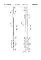
- FIG. 7is a side elevation of a first embodiment of a centering guide according to the present invention for use in a posterior approach and without a lordotic distal end;
- FIG. 8is a view taken along line 8--8 of FIG. 7;
- FIG. 9is a top plan view of the centering guide of FIG. 7;
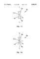
- FIG. 10is a side elevation view of a second embodiment of a centering guide according to the present invention for use in an anterior approach and without a lordotic distal end;
- FIG. 11is a view taken along line 11--11 of FIG. 10;
- FIG. 12is a top plan view of the centering guide of FIG. 10;
- FIG. 13is a side elevation view of a third embodiment of a centering guide according to the present invention for use in an anterior approach and with a lordotic distal end;
- FIG. 14is a view taken along line 14--14 of FIG. 13;
- FIG. 15is a top plan view of the centering guide of FIG. 13;
- FIG. 16is a side elevation view of a fourth embodiment of the centering guide according to the present invention for use in a posterior approach and with a lordotic distal end;
- FIG. 17is a view taken along line 17--17 of FIG. 16;
- FIG. 18is a top plan view of the centering guide of FIG. 16;
- FIG. 19is a side elevation tube of a prior art drill tube for use with the present invention.
- FIG. 20is a view taken along line 21--21 of FIG. 19;
- FIG. 21is an enlarged side elevation view of a distal end of the drill tube of FIG. 19;
- FIG. 22is a side elevation view of a prior art boring tool for use with the present invention.
- FIG. 23is an elevation view of a proximal end of the boring tool of FIG. 22;
- FIG. 24is an enlarged view of a boring head of the boring tool of FIG. 22;
- FIG. 25is an end elevation view of a distal end of the boring head of FIG. 24;
- FIG. 26is a side elevation view of a prior art tap for use with the present invention.
- FIG. 27is a view taken along line 27--27 of FIG. 26;
- FIG. 28is an enlarged sectional view of threaded cutting teeth on the tool of FIG. 26;
- FIG. 29is a side elevation view of an implant driver for use with the present invention.
- FIG. 30is an end view of a hub on a distal end of the tool of FIG. 29;
- FIG. 31is a view taken along line 31--31 of FIG. 29;
- FIG. 32is a side elevation view of a shaft of a tool of FIG. 29 showing an attachment collet
- FIG. 33is a cross sectional view of FIG. 32 taken along line 33--33;
- FIG. 34is a side elevation view of a protective sleeve for use on the drill tube of FIG. 19;
- FIG. 35is an end elevation view of the sleeve of FIG. 34;
- FIG. 36is a schematic posterior to anterior view of two vertebrae separated by a disc space and showing a dura extending centrally along a mid line between the vertebrae;
- FIG. 37is the view of FIG. 30 with a dura retracted to a left side;
- FIG. 38is the view of FIG. 37 with a centering guide of the present invention such as that shown in FIG. 7 inserted into the disc space between the vertebrae prior to the centering guide being rotated to a distraction position;
- FIG. 39is the view of FIG. 38 with the centering guide rotated to a distraction position
- FIG. 40is a plan view of a disc space showing the elements of FIG. 39;
- FIG. 41is a view taken along line 41--41 of FIG. 40;
- FIG. 42is the view of FIG. 39 with a drill tube of FIG. 19 inserted into position and guided by the centering guide;
- FIG. 43is a plan view of the elements of FIG. 42 with the drill tube shown in section;
- FIG. 44is the view of FIG. 43 following formation of a bore in the disc space and vertebrae and showing retraction of a boring tool through the drill tube;
- FIG. 45is the view of FIG. 44 following formation of a tapped thread in the bore of FIG. 44 and showing removal of the tapping tool through the drill tube;
- FIG. 46is the view of FIG. 45 showing an implant inserted into the threaded bore of FIG. 45 and showing removal of the implant driving tool through the drill tube;
- FIG. 47is a posterior-to-anterior view showing a dura retracted to a right side over an inserted implant and with the centering guide reversed and with a drill tube positioned against the centering guide prior to formation of a bore on the left side of the vertebra;
- FIG. 48is a plan view of the elements of FIG. 47 with the drill tube shown in section;
- FIG. 49is an anterior-to-posterior view of two vertebrae separated by a disc space and showing a non-lordotic, anterior approach centering guide of the present invention (such as that shown in FIG. 10) and shown inserted into the disc space between the vertebrae and with a drill tube being guided by the centering guide;
- FIG. 50is the view of FIG. 49 showing an implant inserted into a formed bore on a left side of the vertebrae and with the drill tube moved to be guided by an opposite side of the centering guide prior to formation of a bore on the right side of the vertebra;
- FIG. 51shows a drill tube of FIG. 19 and a protective sleeve of FIG. 34 guided by a posterior centering guide of FIG. 7;
- FIG. 52shows a still further embodiment of a centering guide
- FIG. 53is a side elevation view of an alternative embodiment of a drill tube for use with the centering guide of the present invention.
- FIG. 54is a view taken along line 54--54 of FIG. 53;
- FIG. 55is the view of FIG. 53 with drill tube rotated 90° about its longitudinal axis.
- FIG. 56is a view taken along line 56--56 of FIG. 53.
- the implant 10(FIGS. 1--6) is a hollow cylinder 12 having male, square-profile threads 14 exposed on the exterior cylindrical surface of cylinder 12.
- the cylinderincludes a forward interior chamber 16 and a rear interior chamber 17 separated by a reinforcing rib 19. A bond slurry or bone chips may be compacted into chambers 16, 17.
- a first plurality of holes 18extend radially through the cylinder wall and communicate with the chambers 16, 17.
- a second (and enlarged) plurality of holes 21are disposed on diametrically opposed sides of the implant 10.
- a rear end 22 of the implanthas a slot 24 which communicates with the chamber 17.
- the slot 24allows the bone slurry or bone chips to be impacted into the implant 10.
- a slot 25is defined by rib 19.
- the slot. 25is sized to receive a distal end of a tool (as will be more fully described) to place the implant within a bore formed between opposing vertebrae.
- End caps(not shown) may be used with the implant. Such end caps are shown in U.S. Pat. No. 5,489,307.
- the technique of the present inventionwill be performed with a prescribed kit of tools.
- the tools of the kitwill now be described. It will be appreciated that the method of surgery can be practiced using a wide variety of tools of different size and shapes.
- implants 10having minor outside diameters (D m ) of 3 mm, 5 mm, 7 mm, 9 mm, 11 mm, 13 mm, 15 mm, 17 mm, 19 mm and 21 mm with lengths (L) of 10 mm, 12 mm, 14, mm 16 mm, 18 mm, 20 mm, 24 mm, 28 mm, 30 mm, 32 mm, 34 mm, 38 mm, 42 mm and 44 mm, respectively, are anticipated to accommodate various spine locations and sizes.
- the major outside diameters (D M ) of the implants 10are 2.5 mm larger than the minor outside diameters D m .
- a reaming tool 126is sized for particular sizes of implants. Namely, the reaming tool 126 must form a bore sized to receive the implant. Since ten sizes of implants are anticipated, ten sizes of boring tools 126 are anticipated as will become apparent to one of ordinary skill in the art.
- the present inventionutilizes a novel centering guide to ensure accurate positioning of a drill tube prior to forming a bore and placing an implant.
- a centering guide 100is shown for use in an anterior approach where a surgeon is approaching the disc space from an anterior side of the patient.
- the centering guide 100 1is a rigid rod extending from a distal end 102 1 to a proximal end 104 1 along a longitudinal axis X 1 --X 1 .
- the distal end 102 1is rounded to facilitate easy insertion of the distal end 102 1 into the disc space.
- the anterior guide 100 1has, in cross section, a major transverse axis Y 1 --Y 1 with the guide being symmetrical about the axis Y 1 --Y 1 and axis X 1 --X 1 .
- the guide 100 1has a distraction portion 106 1 .
- the distraction portion 106 1is defined by parallel and spaced-apart side edges 108 1 which are spaced apart by a distance equal to desired distraction of the vertebrae.
- the side edges 108 1act against the end plates of the opposing vertebrae to urge the vertebrae apart.
- the end plateshold the centering guide 100 1 with the axis X 1 --X 1 centrally positioned between the end plates. While the tool proximal end 104 1 can be moved left or right relative to the vertebrae, the precise central positioning of the proximal end 104 1 can be determined through x-ray analysis following placement of the centering guide 100 1 such that a surgeon can be assured that the longitudinal axis X 1 --X 1 extends perpendicular to a transverse plane of the vertebrae.
- the distraction portion 106 1is provided with a plurality of indicia 110 1 in the form of grooves positioned at 5 millimeter increments from the distal end 102 1 .
- the grooves 110 1are detectable in x-ray films to permit a surgeon to measure the degree of insertion of the distal end 102 1 into a disc space.
- the guide 100 1includes a stop 109 1 on edges 108 1 . The stop 109 1 abuts vertebrae to prevent further insertion of guide 100 1 beyond full insertion of portion 106 1 .
- the guide surfaces 112 1 , 114 1are concave and have a radius of curvature equal to a radius of curvature of a drill tube as will be described.
- the proximal end 104 1is provided with a hole 105 1 to permit a surgeon to place a tool (not shown) into the hole 105 1 to twist the centering guide 100 1 to release the centering guide 100 1 if necessary.
- an angled hole 107 1is provided near portion 106 1 to permit insertion of a rod (not shown) into hole 107 1 to permit a surgeon to force the guide 100 1 to the mid-line of vertebrae.
- FIGS. 7-9show a centering guide 100 2 similar to that of FIGS. 10-13 but differing due to the fact that centering guide 100 1 of FIGS. 7-9 is intended for use in a posterior approach where a surgeon approaches the vertebrae from the posterior side of the patient.
- centering guide 100 1 of FIGS. 7-9is intended for use in a posterior approach where a surgeon approaches the vertebrae from the posterior side of the patient.
- simple elementsare numbered similarly with the addition of subscripts to distinguish the embodiments.
- the centering guide 100 2 of FIGS. 7-9is for a non-lordotic parallel distraction appliance where the side edges 108 2 are spaced apart in parallel alignment at the distraction portion 106 2 .
- the centering guide 100 2 of FIGS. 7-9is not symmetrical about its major transverse axis Y 2 --Y 2 (although it is symmetrical about axis X 2 --X 2 .
- the centering guide 100 2 of FIGS. 7-9includes only a first concave guiding surface 112 2 extending on one side of the centering guide 100 2 .
- the opposite surface 114 2is a convex surface to present a smooth surface opposing a dura following insertion of the centering guide 100 2 as will be described.
- the centering guides 100 1 , 100 2 of FIGS. 7-12both show distraction portions 106 1 , 106 2 having distracting edges 108 1 , 108 2 which are parallel and spaced apart. From time to time, it may be desirable to ensure that end plates of opposing vertebrae are retained at a desired degree of lordosis (i.e., with a non-parallel angle between end plates of the opposing vertebrae).
- FIGS. 16-18show a centering guide 100 3 for a posterior approach and having a lordotic distraction portion 106 3 .
- the distraction portion 106 3has side edges 108 3 placed at an angle, A, equal to the desired degree of lordosis.
- the centering guide 100 3 of FIGS. 16-18is identical to that of FIGS. 7-9.
- FIGS. 13-15show a lordotic centering guide 100 4 for use in an anterior approach.
- the distractor end 106 4 of the tool 100 4has distracting side edges 108 4 set at a lordotic angle, A', equal to but reverse that of the embodiment of FIGS. 16-18.
- the centering guide 100 4 of FIGS. 13-15is identical to that of FIGS. 10-12.
- Laparoscopic versions of both the lordotic and non-lordotic centering guidescan also be provided. Although not shown in the drawings, such laparoscopic centering guides would have a shorter length than the non-laparoscopic centering guides shown in the drawings.
- a non-lordotic, laparoscopic anterior centering guidewould be identical to that of guide 100 1 (FIG. 10) but have its axial length detachable so that the terminal end 104 1 is spaced from the distal tip 102 1 by about 3 inches. After insertion of the portion 106 1 into the disc space, approximately 1.5 inches of the guide surfaces 112 1 , 144 1 would protrude beyond the vertebrae and provide a guide surface for directing a laparoscopic drill tube. The design would also permit the maintenance of insufflation.
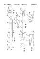
- a drill tube 92(FIGS. 20-22) is provided in the form of a hollow cylindrical tube 94.
- the distal end 96 of the tube 94is provided with axially projecting teeth 98.
- the proximal end 99 of the tube 94is flared outwardly.
- ten sizes of tube 92are required with inside diameters D DT to slip in close tolerance over ten sizes of implants 10 (i.e., D DT is 0.5 mm larger than D M )
- the teeth 98each have a length, T L , of preferably 3 mm.
- the valleys 97are flat to provide stop surfaces to hit bone as teeth 98 are forced into vertebrae. This helps prevent the drill tube 92 from being forced too far into bone.
- the drill tube 92is identical to that shown in U.S. Pat. No. 5,489,307.
- FIGS. 53-56An alternative embodiment of a drill tube 192 is illustrated in FIGS. 53-56.
- the drill tubeis a hollow cylindrical tube 194 with an outside diameter having a radius of curvature to match the radius of curvature of the guide surfaces 112 1 , 114 1 .
- the distal end 196 of the tube 194includes diametrically opposed and axially projecting sharpened teeth 198 for penetration into vertebrae.
- Diametrically opposed and axially extending retraction paddles 199are provided ninety degrees offset from the teeth 198 (with reference to the longitudinal axis (X' D --X' D ).
- the paddles 199have a width (W in FIG. 54) equal to the desired distraction of the vertebrae.
- the proximal end 197 of the tube 194is a handle to be gripped by a surgeon.
- the tube 194has a length L D measured from the base of the teeth 198 and retraction paddles 199 to the base of the handle 197.
- the length L Dis equal to the length of a centering guide (such as the length of guide 100 1 of FIG. 10) between the proximal end 104 1 and the insertion portion 106 1 . Therefore, when the insertion portion 106 1 is fully inserted into the disc space, the end 104 1 buts against the handle 197 when the teeth 198 are forced into the vertebrae.
- a vertebral reamer 126(or boring tool) (FIGS. 22 through 25), is provided for forming a bore.
- the reamer 126is such as that shown in U.S. Pat. No. 5,489,307.
- the reamer 126includes a shaft 128.
- a distal end of the shaftis provided with a reamer end 130 having side and end cutting blades 131.
- a proximal end of the shaftis provided with an outwardly flared hub 132. Extending from hub 132 is an axial shaft 134.
- the outside diameter D R of reamer 126equals the minor outside diameter D m of implants 10.
- the diameter D RG of the guide hub 133equals the inner diameter of the drill tube D DT .
- a bone tap 142(FIGS. 26-28) is provided, having a shaft 144.
- the top 142is such as that shown in U.S. Pat. No. 5,489,307.
- a tapping head 146At the distal end of the shaft 144 is a tapping head 146 having tapping threads 148.
- an enlarged diameter portion 156Near the proximal end of the shaft 144 is an enlarged diameter portion 156 having an outwardly flared flange 158.
- a handle 160is secured to an enlarged portion 156.
- the shaft 144is also enlarged at portion 162 adjacent tapping head 146.
- the enlarged portion 156is sized with diameter D 8 to be received, in close tolerance, within the drill tube 92 such that the tube 92 will guide the tap 142 as will be more fully described.
- Diameter D Tis equal to the major outside diameter D M of implant 10.
- the head 146has a minor outside diameter D t (i.e., the diameter without threads 148) equal to the minor outside diameter D m of the implants 10.
- an implant driver 164(FIGS. 29 through 33) is provided.
- the driver 164is such as that shown in U.S. Pat. No. 5,487,307.
- a driveris also shown in U.S. Pat. No. 5,609,636.
- the driver 164includes a shaft 166 having a reduced diameter distal portion 166a.
- a distal end of the shaft 166is provided with a hub 168 sized to be received within slot 24 of the implant 10 to urge the implant 10 to rotate as the implant driver 164 is rotated.
- the implant driver 164includes a stepped enlarged portion 170 including a first diameter portion 172, a second diameter portion 174 and a third diameter portion 176 to accommodate the different diameters of drill tubes 92.
- a handle 178is secured to the shaft 164.
- Grooves 180,180aare formed on the shafts 166,166a and extend along their axial lengths. The grooves 180 provide a means for a surgeon to sight the alignment of the implant.
- FIGS. 32-33show the implant driver 164 with a collet 171.
- the collet 171has a cylindrical, knurled body 173 slidably carried on shaft 166a.
- a pin 175 extending from body 173 into groove 180apermits collet 171 to slide on shaft 166 but not rotate.
- Four prongs 177extend axially from body 173 toward hub 168.
- shaft 166is passed through end opening 24 of implant 10.
- Hub 168is received within slot 25.
- the prongs 177are forced by a surgeon pushing on body 171 for the prongs 177 to be urged between opposing surfaces of the implant 10 and shaft 166a to thereby securely capture the implant 10 on driver 164.
- the implant 10cannot inadvertently fall off.
- the Figures showing the method of the invention, e.g., FIG. 46,does not show use of collet 171).
- Drill tube 92is passed through a patient's body to an implant site.
- a drill tube sheath 300is provided (FIGS. 34, 35).
- the sheath 300is such as that: shown in U.S. Pat. No. 5,489,307.
- the sheath 300is a hollow tube with inside diameter D s slightly smaller than the outside diameter of drill tube 92 (accordingly, ten sizes of sheath 300 are required).
- the sheath 300has an axial slit 301 extending its entire length.
- the sheath 300has a blunt distal end 302 and a flared proximal end 304.
- the sheathis slipped onto the drill tubs 92 with end 302 extending beyond the teeth 98.
- the blunt end 302covers the teeth and prevents the unwanted cutting of vessels, nerves or organs.
- the end 302abuts the vertebrae.
- the sheath 300slides on the tube 92 until teeth 98 abut the vertebrae.
- sheath 300remains in place whenever drill tube 92 are used. However, for ease of illustration, sheath 300 is not shown in FIGS. 42-50.
- a posterior approacha surgeon seeks access to the spine through the back of the patient.
- Another alternative approachis the lateral approach, where the patient is on his side and a single cage is inserted across the disk space.
- An alternative approachis an anterior approach where the surgeon seeks access to the spine through the abdomen of a patient. The approaches can be done through open surgery or through laparoscopic surgery.
- the surgeonidentifies an implant 10 of desired size and the surgeon determines the desired amount of distraction of the disc space 202 to be required before placement of the implant 10.
- the surgeonshould ensure that the device will remain within the lateral borders of the intervertebral disc space 202 while also penetrating at least 3 mm into the vertebral bodies 200,200' cephalad and caudal to the disc.
- a patientis placed on the operating table in either a prone or kneeling-sitting position. At the discretion of the surgeon, the spine is flexed slightly. Anesthesia is administered.
- Exposure of the intervertebral discis obtained through any suitable technique well-known in the art.
- the facet of the vertebraeis removed in as limited amount as possible to permit insertion of the instruments and the implants.
- Preferably, bone dissected from the lamina, facets and spinous processare preserved for -Later use as bone graft.
- FIG. 36shows two vertebrae 200,200' separated by a disc space 202.
- disc materialis not shown in space 202 having an undistracted thickness T R .
- a dura 204extends between the vertebrae 200,200' and is central-y positioned along a medial line, M, between the vertebrae 200,200'.
- the line Mseparates the disc space 202 and vertebrae 200,200' into a left side L and right side R corresponding to the patient's left and right sides.
- the dura 204is first retracted to the left through any suitable means to expose the disc space 202 and vertebrae 200,200' at the medial line, M.
- a distal end 102 2 of the centering guide 100 2 of FIGS. 7-9is inserted into the disc space 202 in the manner illustrated in FIG. 38 with the distracting side edges 108 2 opposing and in line with the disc space 202.
- the centering tool 100 2is rotated 90° to the position shown in FIG. 39 such that the side edges 108 2 of the distraction portion 106 2 oppose and distract the vertebrae and the convex surface 114 2 is opposing the dura 204 to prevent damage to the dura 204.
- the vertebrae 200,200'are now distracted to a spacing of T D equal to the distance between side edges 108 2 .
- the distraction portion 106 2 of the guide 100 2is forced into the disc space 202 at the mid line M of the disc space 202.
- the size (i.e., the spacing between the side edges 108 2 ) of the centering guide 100 2is selected to distract the annulus fibrosus without causing damage to the surrounding vertebral bone, annular fibers or spinal nerves. Accordingly, it is recommended that a surgeon initially insert a relatively narrow distal end centering guide (e.g., 6 millimeters) followed by successively larger guides until the annulus is distracted to the surgeon's satisfaction.
- the correct maximum size distraction portion 106 2has been chosen, it is left in place.
- the disc space 202has now been stretched so that a parallel distraction of the end plates 201,201' of the vertebrae 200,200' has occurred on both the left and right sides of 1the vertebrae.
- the distraction portion 106 2is fully inserted such that the indicia 110 2 are flush or slightly recessed within the disc space.
- the drill tube 92is placed against the centering guide 100 2 . Since the guiding surface 112 2 of the centering guide 100 2 is concave with a radius of curvature matching the outer radius of curvature of the drill tube 92, the drill tube 92 can be slid along the length of the guide 100 2 into precise position with the axis X D --X D of the drill tube 92 centrally positioned between the end plates 201,201' of the vertebrae 200,200'.
- the drill tube 92will be surrounded by a sliding protective sleeve 300 such as that shown in FIGS. 34-35 and described fully in U.S. Pat. No. 5,489,307.
- the thin wall of the drill sleeve 300has substantially the same radius of curvature as the drill tube 92 and does not materially affect the positioning.
- the addition of the protective sleeve 300increases the spacing of the axis X D --X D of the drill tube 92 from the axis X 2 --X 2 of the guide 100 2 (FIG. 51) but does not alter the central positioning of the axis X D --X D of the drill tube 92 between the end plates 201,201'.
- the drill sleeve protective sleeveis not shown in FIGS. 42-50.
- the preparation of the implant bore 206is completed by inserting the reamer 126 into the drill tube 92 (FIG. 44).
- the reamer 126is rotated with any suitable driver (such as driver 136 shown in U.S. Pat. No. 5,489,307).
- the reamer 126will bore into the disc space 202 and bore equally into and through the end plates 201,201' of the opposing vertebrae.
- the reamer 126is selected to form a bore 206 having a diameter D m equal to the minor outside diameter of the implant 10 (in the case of a cylindrical implant such as that shown in FIGS. 1-6).
- a bone tap 142is passed through the drill tube 92 and rotated to at least partially pretap the bore (FIG. 45). The tap is then removed to expose a tapped bore 207 with the drill tube 92 remaining in place.
- the implant 10may then be packed with a bone graft material.
- the graftmay be autograft obtained previously from the iliac crest or some other graft material (e.g., allograft or artificial bone).
- the implant 10is attached to the implant driver 164 by placing the hub 168 within the slot 25 and securing the implant 10 with the collet 171. The implant 10 is then passed through the drill tube 92.
- the implant 10is threaded into the bore 207 with the implant driver 164 by the surgeon rotating the driver 164 and advancing it into the drill tube 92.
- the larger holes of the implantare oriented in a superior-inferior direction (i.e., the larger holes are facing the vertebrae 200,200').
- the implant driver 164is removed through the drill tube 92 (FIG. 47).
- the drill tube 92is then removed.
- the dura 204is retracted slightly and the centering guide 100 is then removed.
- the dura 204is then retracted to the opposite side and the centering guide 100 2 is repositioned with the disc space 204 but rotated 180° relative to FIG. 39 so that the rounded side 114 2 is facing both the dura 204 and the previously placed implant 10 and the guide surface 112 2 is facing the opposite side of the disc space 202.
- the procedurecan then be repeated by placing the drill tube 92 against the vertebrae with the drill tube 92 aligned by the guide 100 2 as previously described (FIG. 47).
- the surgeonuses the anterior guide 100,100 4 which has concave guiding surfaces 112,114 on opposite sides of the centering guide 100.
- the anterior centering guide 100is placed at the mid line M and a drill tube 92 is guided by a first 112 of the guiding surfaces 112,114 so that a first bore can be formed, tapped and an implant 10 inserted through the drill tube (FIG. 50).
- the centering guide 100remains in place but the drill tube 92 is moved to the opposite side and guided into position by the second guiding surface 114 (FIG. 51).
- a bore 206is then formed by passing the reamer and tap through the drill tube and a second implant is inserted through the drill tube.
- the present inventionis particularly suited for a lateral approach where an elongated single implant is to be placed in the inner vertebral space.
- the present inventionrequires smaller access space to the disc space which is of particular advantage in a lateral approach where there is substantial anatomic structure limiting access to the disc space in a lateral approach at certain vertebrae locations.
- the guide surfacehas been shown as a concave surface 112 having the same radius of curvature of the guided surface of the cylindrical drill tube. It will be appreciated that while a circular arc of a guide surface corresponding to a radius of curvature of a cylindrical drill tube is preferred, a plurality of complementary geometries could be used for the guide surface and the guiding surface.
- the guide surface 112' on the centering guide 100'could be dovetail grooved and the guided surface on the drill tube 92' could be a complementary shaped dovetail rail 93' which slides within the dovetail groove 112'.
- Such a modificationwould preclude non-parallel alignment of the axis X D '--X D ' of the drill tube 92' and the longitudinal axis X'--X' of the centering guide 100'.
- such a modificationwould require accurate alignment of the drill tube 92', whereas in the preferred embodiment previously disclosed, the drill tube 92 may be rotated about its axis X D --X D .
Landscapes
- Health & Medical Sciences (AREA)
- Engineering & Computer Science (AREA)
- Biomedical Technology (AREA)
- Orthopedic Medicine & Surgery (AREA)
- Life Sciences & Earth Sciences (AREA)
- Animal Behavior & Ethology (AREA)
- Veterinary Medicine (AREA)
- Public Health (AREA)
- General Health & Medical Sciences (AREA)
- Heart & Thoracic Surgery (AREA)
- Surgery (AREA)
- Neurology (AREA)
- Transplantation (AREA)
- Oral & Maxillofacial Surgery (AREA)
- Cardiology (AREA)
- Nuclear Medicine, Radiotherapy & Molecular Imaging (AREA)
- Vascular Medicine (AREA)
- Medical Informatics (AREA)
- Molecular Biology (AREA)
- Physical Education & Sports Medicine (AREA)
- Dentistry (AREA)
- Prostheses (AREA)
- Surgical Instruments (AREA)
Abstract
Description
Claims (20)
Priority Applications (7)
| Application Number | Priority Date | Filing Date | Title |
|---|---|---|---|
| US08/921,001US6086595A (en) | 1997-08-29 | 1997-08-29 | Apparatus and method for spinal stabilization |
| US09/116,747US6059790A (en) | 1997-08-29 | 1998-07-16 | Apparatus and method for spinal stabilization |
| AU89205/98AAU8920598A (en) | 1997-08-29 | 1998-08-26 | Apparatus and method for spinal stabilization |
| PCT/US1998/017646WO1999009896A1 (en) | 1997-08-29 | 1998-08-26 | Apparatus and method for spinal stabilization |
| US09/364,127US6156040A (en) | 1997-08-29 | 1999-07-30 | Apparatus and method for spinal stablization |
| US09/717,531US6562041B1 (en) | 1997-08-29 | 2000-11-21 | Apparatus and method for spinal stabilization |
| US10/438,249US20040015168A1 (en) | 1997-08-29 | 2003-05-13 | Apparatus and method for spinal stabilization |
Applications Claiming Priority (1)
| Application Number | Priority Date | Filing Date | Title |
|---|---|---|---|
| US08/921,001US6086595A (en) | 1997-08-29 | 1997-08-29 | Apparatus and method for spinal stabilization |
Related Child Applications (2)
| Application Number | Title | Priority Date | Filing Date |
|---|---|---|---|
| US09/116,747Continuation-In-PartUS6059790A (en) | 1997-08-29 | 1998-07-16 | Apparatus and method for spinal stabilization |
| US09/364,127DivisionUS6156040A (en) | 1997-08-29 | 1999-07-30 | Apparatus and method for spinal stablization |
Publications (1)
| Publication Number | Publication Date |
|---|---|
| US6086595Atrue US6086595A (en) | 2000-07-11 |
Family
ID=25444763
Family Applications (4)
| Application Number | Title | Priority Date | Filing Date |
|---|---|---|---|
| US08/921,001Expired - Fee RelatedUS6086595A (en) | 1997-08-29 | 1997-08-29 | Apparatus and method for spinal stabilization |
| US09/364,127Expired - LifetimeUS6156040A (en) | 1997-08-29 | 1999-07-30 | Apparatus and method for spinal stablization |
| US09/717,531Expired - LifetimeUS6562041B1 (en) | 1997-08-29 | 2000-11-21 | Apparatus and method for spinal stabilization |
| US10/438,249AbandonedUS20040015168A1 (en) | 1997-08-29 | 2003-05-13 | Apparatus and method for spinal stabilization |
Family Applications After (3)
| Application Number | Title | Priority Date | Filing Date |
|---|---|---|---|
| US09/364,127Expired - LifetimeUS6156040A (en) | 1997-08-29 | 1999-07-30 | Apparatus and method for spinal stablization |
| US09/717,531Expired - LifetimeUS6562041B1 (en) | 1997-08-29 | 2000-11-21 | Apparatus and method for spinal stabilization |
| US10/438,249AbandonedUS20040015168A1 (en) | 1997-08-29 | 2003-05-13 | Apparatus and method for spinal stabilization |
Country Status (3)
| Country | Link |
|---|---|
| US (4) | US6086595A (en) |
| AU (1) | AU8920598A (en) |
| WO (1) | WO1999009896A1 (en) |
Cited By (69)
| Publication number | Priority date | Publication date | Assignee | Title |
|---|---|---|---|---|
| US6277122B1 (en)* | 1999-10-15 | 2001-08-21 | Sdgi Holdings, Inc. | Distraction instrument with fins for maintaining insertion location |
| US6283966B1 (en)* | 1999-07-07 | 2001-09-04 | Sulzer Spine-Tech Inc. | Spinal surgery tools and positioning method |
| US20020156481A1 (en)* | 1998-04-09 | 2002-10-24 | Boyd Lawrence M. | Method and instrumentation for vertebral interbody fusion |
| US6500180B1 (en) | 1999-10-20 | 2002-12-31 | Sdgi Holdings, Inc. | Methods and instrumentation for distraction of a disc space |
| US20030082169A1 (en)* | 2001-11-01 | 2003-05-01 | Boyd Lawrence M. | System and method for the pretreatment of the endplates of an intervertebral disc |
| US6562045B2 (en) | 2001-02-13 | 2003-05-13 | Sdgi Holdings, Inc. | Machining apparatus |
| US6575899B1 (en) | 1999-10-20 | 2003-06-10 | Sdgi Holdings, Inc. | Methods and instruments for endoscopic interbody surgical techniques |
| US6575981B1 (en) | 1999-02-04 | 2003-06-10 | Sdgi Holdings, Inc. | Methods and instrumentation for vertebral interbody fusion |
| US6582437B2 (en) | 1999-08-26 | 2003-06-24 | Sdgi Holdings, Inc. | Devices and methods for implanting fusion cages |
| US20030135277A1 (en)* | 2001-11-26 | 2003-07-17 | Sdgi Holdings, Inc. | Implantable joint prosthesis and associated instrumentation |
| US6632225B2 (en)* | 2001-06-20 | 2003-10-14 | Zimmer, Inc. | Method and apparatus for resecting a distal femur and a proximal tibia in preparation for implanting a partial knee prosthesis |
| US20030199982A1 (en)* | 1998-09-04 | 2003-10-23 | Sdgi Holdings, Inc. | Peanut spectacle multi discoid thoraco-lumbar disc prosthesis |
| US20030199738A1 (en)* | 2000-08-08 | 2003-10-23 | Sdgi Holdings,Inc. | Clamping apparatus and methods |
| US6648895B2 (en) | 2000-02-04 | 2003-11-18 | Sdgi Holdings, Inc. | Methods and instrumentation for vertebral interbody fusion |
| US20040010259A1 (en)* | 2002-03-12 | 2004-01-15 | Waldemar Link Gmbh & Co. | Cervical prosthesis and instrumentation therefor |
| US20040054411A1 (en)* | 2000-08-08 | 2004-03-18 | Sdgi Holdings, Inc. | Wear-resistant endoprosthetic devices |
| US20040098131A1 (en)* | 1996-07-22 | 2004-05-20 | Sdgi Holdings, Inc. | Human spinal disc prosthesis |
| US6743234B2 (en) | 1999-02-04 | 2004-06-01 | Sdgi Holdings, Inc. | Methods and instrumentation for vertebral interbody fusion |
| US20040158254A1 (en)* | 2003-02-12 | 2004-08-12 | Sdgi Holdings, Inc. | Instrument and method for milling a path into bone |
| US20040177494A1 (en)* | 2002-03-12 | 2004-09-16 | Waldemar Link Gmbh & Co | Instrument set for fitting an intervertebral joint prosthesis |
| US20050027300A1 (en)* | 2003-03-31 | 2005-02-03 | Depuy Spine, Inc. | Method and apparatus for artificial disc insertion |
| US20050059976A1 (en)* | 2000-08-08 | 2005-03-17 | Sdgi Holdings, Inc. | Method and apparatus for stereotactic implantation |
| US20050071009A1 (en)* | 2000-09-08 | 2005-03-31 | Nabil L. Muhanna, M.D. | System and methods for inserting a vertebral spacer |
| US20050182414A1 (en)* | 2004-01-08 | 2005-08-18 | Richard Manzi | Apparatus and method for injecting fluent material at a distracted tissue site |
| US20050288677A1 (en)* | 2005-10-03 | 2005-12-29 | Inventit, Llc | Spinal surgery distractor with an integrated retractor |
| US20060009851A1 (en)* | 2004-06-29 | 2006-01-12 | Keith Collins | Percutaneous methods for injecting a curable biomaterial into an intervertebral space |
| US20060036261A1 (en)* | 2004-08-13 | 2006-02-16 | Stryker Spine | Insertion guide for a spinal implant |
| US20060116688A1 (en)* | 1998-04-09 | 2006-06-01 | Boyd Lawrence M | Method and instrumentation for vertebral interbody fusion |
| US20060223639A1 (en)* | 2004-12-20 | 2006-10-05 | Aruze Corp. | Game chip |
| US20060241762A1 (en)* | 2003-12-11 | 2006-10-26 | Deltacor Gmbh | Height-adjustable spinal implant and operating instrument for the implant |
| US7147665B1 (en) | 1998-07-22 | 2006-12-12 | Sdgi Holdings, Inc. | Threaded cylindrical multidiscoid single or multiple array disc prosthesis |
| US20070016221A1 (en)* | 1999-09-14 | 2007-01-18 | Boris Beyersdorff | Insertion instrument for an intervertebral implant |
| US20070043361A1 (en)* | 2005-02-17 | 2007-02-22 | Malandain Hugues F | Percutaneous spinal implants and methods |
| US20070162134A1 (en)* | 2002-12-13 | 2007-07-12 | Theirry Marnay | Intervertebral implant, insertion tool and method of inserting same |
| US20070208347A1 (en)* | 1997-01-02 | 2007-09-06 | Zucherman James F | Spine distraction implant and method |
| US20070208346A1 (en)* | 2003-04-28 | 2007-09-06 | Theirry Marnay | Instruments and method for preparing an intervertebral space for receiving an artificial disc implant |
| US20070233261A1 (en)* | 2006-03-28 | 2007-10-04 | Depuy Spine, Inc. | Artificial Disc Replacement Using Posterior Approach |
| US20070233244A1 (en)* | 2006-03-28 | 2007-10-04 | Depuy Spine, Inc. | Artificial Disc Replacement Using Posterior Approach |
| US20070276406A1 (en)* | 2004-02-09 | 2007-11-29 | Depuy Spine, Inc | Systems and Methods for Spinal Surgery |
| US20080071281A1 (en)* | 2006-09-08 | 2008-03-20 | Spine Wave Inc. | Modular Injection Needle and Seal Assembly |
| US20080147191A1 (en)* | 2006-12-14 | 2008-06-19 | Depuy Spine, Inc. | Buckling disc replacement |
| US20080147190A1 (en)* | 2006-12-14 | 2008-06-19 | Warsaw Orthopedic, Inc. | Interspinous Process Devices and Methods |
| US20080215058A1 (en)* | 1997-01-02 | 2008-09-04 | Zucherman James F | Spine distraction implant and method |
| US20090088847A1 (en)* | 2007-10-01 | 2009-04-02 | Manoj Krishna | Surgical instrument system |
| US20090182341A1 (en)* | 2002-03-12 | 2009-07-16 | Cervitech, Inc. | Instrument set for fitting an intervertebral jont prosthesis |
| US20090234397A1 (en)* | 2004-11-22 | 2009-09-17 | Petersen David A | Methods and Surgical Kits for Minimally-Invasive Facet Joint Fusion |
| US7641692B2 (en) | 2000-08-08 | 2010-01-05 | Warsaw Orthopedic, Inc. | Implantable joint prosthesis |
| US7799081B2 (en) | 2004-09-14 | 2010-09-21 | Aeolin, Llc | System and method for spinal fusion |
| US7803162B2 (en) | 2003-07-21 | 2010-09-28 | Spine Solutions, Inc. | Instruments and method for inserting an intervertebral implant |
| US7927354B2 (en) | 2005-02-17 | 2011-04-19 | Kyphon Sarl | Percutaneous spinal implants and methods |
| US20110224672A1 (en)* | 2004-10-26 | 2011-09-15 | Orthovita, Inc. | Surgical instruments and method of using same |
| US8021392B2 (en)* | 2004-11-22 | 2011-09-20 | Minsurg International, Inc. | Methods and surgical kits for minimally-invasive facet joint fusion |
| US8029567B2 (en) | 2005-02-17 | 2011-10-04 | Kyphon Sarl | Percutaneous spinal implants and methods |
| US8066750B2 (en) | 2006-10-06 | 2011-11-29 | Warsaw Orthopedic, Inc | Port structures for non-rigid bone plates |
| US8096994B2 (en) | 2005-02-17 | 2012-01-17 | Kyphon Sarl | Percutaneous spinal implants and methods |
| US8096995B2 (en) | 2005-02-17 | 2012-01-17 | Kyphon Sarl | Percutaneous spinal implants and methods |
| US8114131B2 (en) | 2008-11-05 | 2012-02-14 | Kyphon Sarl | Extension limiting devices and methods of use for the spine |
| US8167890B2 (en) | 2005-02-17 | 2012-05-01 | Kyphon Sarl | Percutaneous spinal implants and methods |
| US20120191103A1 (en)* | 2009-09-07 | 2012-07-26 | Nobel Biocare Services Ag | Components for guided threading of bone |
| US8282641B2 (en) | 2006-03-28 | 2012-10-09 | Depuy Spine, Inc. | Methods and instrumentation for disc replacement |
| US8337500B2 (en) | 2006-07-31 | 2012-12-25 | Synthes Usa, Llc | Drilling/milling guide and keel cut preparation system |
| US8425603B2 (en) | 2008-12-22 | 2013-04-23 | Synthes Usa, Llc | Orthopedic implant with flexible keel |
| US8506634B2 (en) | 1999-07-02 | 2013-08-13 | DePuy Synthes Products, LLC | Intervertebral implant |
| US8568482B2 (en) | 2003-05-14 | 2013-10-29 | Kilian Kraus | Height-adjustable implant to be inserted between vertebral bodies and corresponding handling tool |
| US20140257391A1 (en)* | 2004-04-20 | 2014-09-11 | James L. Chappuis | Internal Pedicle Insulator Apparatus and Method of Use |
| US8840617B2 (en) | 2010-02-26 | 2014-09-23 | Warsaw Orthopedic, Inc. | Interspinous process spacer diagnostic parallel balloon catheter and methods of use |
| US8998990B2 (en) | 2006-07-24 | 2015-04-07 | DePuy Synthes Products, LLC | Intervertebral implant with keel |
| US9259299B2 (en) | 2009-09-07 | 2016-02-16 | Nobel Biocare Services Ag | Components for threading of bone |
| US10327787B2 (en) | 2015-12-28 | 2019-06-25 | Nuvasive, Inc | Adjustable depth drill guide |
Families Citing this family (57)
| Publication number | Priority date | Publication date | Assignee | Title |
|---|---|---|---|---|
| US5782919A (en) | 1995-03-27 | 1998-07-21 | Sdgi Holdings, Inc. | Interbody fusion device and method for restoration of normal spinal anatomy |
| US6245072B1 (en) | 1995-03-27 | 2001-06-12 | Sdgi Holdings, Inc. | Methods and instruments for interbody fusion |
| US6059790A (en)* | 1997-08-29 | 2000-05-09 | Sulzer Spine-Tech Inc. | Apparatus and method for spinal stabilization |
| US6478800B1 (en) | 2000-05-08 | 2002-11-12 | Depuy Acromed, Inc. | Medical installation tool |
| CA2428546A1 (en) | 2000-11-13 | 2002-05-16 | Frank H. Boehm, Jr. | Device and method for lumbar interbody fusion |
| US6814738B2 (en) | 2001-01-23 | 2004-11-09 | Depuy Acromed, Inc. | Medical impacting device and system |
| US20020138147A1 (en)* | 2001-03-22 | 2002-09-26 | Surgical Dynamics, Inc. | Apparatus for fusing adjacent bone structures |
| US6719794B2 (en) | 2001-05-03 | 2004-04-13 | Synthes (U.S.A.) | Intervertebral implant for transforaminal posterior lumbar interbody fusion procedure |
| US6974480B2 (en) | 2001-05-03 | 2005-12-13 | Synthes (Usa) | Intervertebral implant for transforaminal posterior lumbar interbody fusion procedure |
| US6652533B2 (en) | 2001-09-20 | 2003-11-25 | Depuy Acromed, Inc. | Medical inserter tool with slaphammer |
| US6709439B2 (en) | 2001-10-30 | 2004-03-23 | Depuy Spine, Inc. | Slaphammer tool |
| AR038680A1 (en) | 2002-02-19 | 2005-01-26 | Synthes Ag | INTERVERTEBRAL IMPLANT |
| US20040153076A1 (en)* | 2002-10-29 | 2004-08-05 | Wamis Singhatat | Ligament graft cage fixation device |
| CA2515247C (en) | 2003-02-06 | 2010-10-05 | Synthes (U.S.A.) | Intervertebral implant |
| US7354442B2 (en)* | 2003-05-05 | 2008-04-08 | Warsaw Orthopedic, Inc. | Bone anchor and methods of using the same |
| US20050209610A1 (en) | 2004-03-03 | 2005-09-22 | Scimed Life Systems, Inc. | Radially adjustable tissue removal device |
| US20050197661A1 (en)* | 2004-03-03 | 2005-09-08 | Scimed Life Systems, Inc. | Tissue removal probe with sliding burr in cutting window |
| US8784421B2 (en) | 2004-03-03 | 2014-07-22 | Boston Scientific Scimed, Inc. | Apparatus and methods for removing vertebral bone and disc tissue |
| US20050209622A1 (en)* | 2004-03-03 | 2005-09-22 | Scimed Life Systems, Inc. | Tissue removal probe with irrigation and aspiration ports |
| US20060095136A1 (en)* | 2004-11-03 | 2006-05-04 | Mcluen Design, Inc. | Bone fusion device |
| US8597360B2 (en) | 2004-11-03 | 2013-12-03 | Neuropro Technologies, Inc. | Bone fusion device |
| US7828830B2 (en)* | 2005-05-12 | 2010-11-09 | Lanx, Inc. | Dynamic spinal stabilization |
| US20060271048A1 (en)* | 2005-05-12 | 2006-11-30 | Jeffery Thramann | Pedicle screw based vertebral body stabilization apparatus |
| US20070093897A1 (en)* | 2005-10-21 | 2007-04-26 | Stryker Spine (In France) | System and method for fusion cage implantation |
| US7559930B2 (en)* | 2006-01-26 | 2009-07-14 | Warsaw Orthopedic, Inc. | Surgical tool and method with an actuation mechanism for controlling reciprocation and locking of an anti-rotation member relative to an engagement member for facilitating positioning of an intervertebral device |
| US8377072B2 (en) | 2006-02-06 | 2013-02-19 | Depuy Spine, Inc. | Medical device installation tool |
| EP1988855A2 (en) | 2006-02-27 | 2008-11-12 | Synthes GmbH | Intervertebral implant with fixation geometry |
| US7615079B2 (en)* | 2006-04-20 | 2009-11-10 | Meditech Advisors, Llc | Monorail system |
| US8790403B2 (en)* | 2006-04-20 | 2014-07-29 | K2M, Inc. | Monorail system |
| US8303601B2 (en) | 2006-06-07 | 2012-11-06 | Stryker Spine | Collet-activated distraction wedge inserter |
| US9526525B2 (en) | 2006-08-22 | 2016-12-27 | Neuropro Technologies, Inc. | Percutaneous system for dynamic spinal stabilization |
| US8740941B2 (en) | 2006-11-10 | 2014-06-03 | Lanx, Inc. | Pedicle based spinal stabilization with adjacent vertebral body support |
| JP2011502708A (en) | 2007-11-16 | 2011-01-27 | ジンテス ゲゼルシャフト ミット ベシュレンクテル ハフツング | Low profile intervertebral implant |
| CN102256570B (en) | 2008-11-07 | 2015-09-02 | 斯恩蒂斯有限公司 | Spacer and connecting plate assembly between vertebral bodies |
| WO2010107692A1 (en) | 2009-03-16 | 2010-09-23 | Synthes Usa, Llc | System and method for stabilizing vertebrae in spine surgery through a lateral access channel |
| US9028553B2 (en) | 2009-11-05 | 2015-05-12 | DePuy Synthes Products, Inc. | Self-pivoting spinal implant and associated instrumentation |
| WO2011111301A1 (en)* | 2010-03-09 | 2011-09-15 | 国立大学法人神戸大学 | Inter-spinous process implant |
| EP2547292B1 (en) | 2010-03-16 | 2019-04-24 | Pinnacle Spine Group, LLC | Ntervertebral implants and graft delivery systems |
| WO2012088238A2 (en) | 2010-12-21 | 2012-06-28 | Synthes Usa, Llc | Intervertebral implants, systems, and methods of use |
| US9358123B2 (en) | 2011-08-09 | 2016-06-07 | Neuropro Spinal Jaxx, Inc. | Bone fusion device, apparatus and method |
| US10420654B2 (en) | 2011-08-09 | 2019-09-24 | Neuropro Technologies, Inc. | Bone fusion device, system and method |
| WO2013023096A1 (en) | 2011-08-09 | 2013-02-14 | Neuropro Technologies, Inc. | Bone fusion device, system and method |
| US9380932B1 (en) | 2011-11-02 | 2016-07-05 | Pinnacle Spine Group, Llc | Retractor devices for minimally invasive access to the spine |
| US10159583B2 (en) | 2012-04-13 | 2018-12-25 | Neuropro Technologies, Inc. | Bone fusion device |
| US9532883B2 (en) | 2012-04-13 | 2017-01-03 | Neuropro Technologies, Inc. | Bone fusion device |
| US10022245B2 (en) | 2012-12-17 | 2018-07-17 | DePuy Synthes Products, Inc. | Polyaxial articulating instrument |
| WO2014159739A1 (en) | 2013-03-14 | 2014-10-02 | Pinnacle Spine Group, Llc | Interbody implants and graft delivery systems |
| CA2906531C (en) | 2013-03-15 | 2020-10-06 | Neuropro Technologies, Inc. | Bodiless bone fusion device, apparatus and method |
| US9867718B2 (en) | 2014-10-22 | 2018-01-16 | DePuy Synthes Products, Inc. | Intervertebral implants, systems, and methods of use |
| US10973657B2 (en) | 2017-01-18 | 2021-04-13 | Neuropro Technologies, Inc. | Bone fusion surgical system and method |
| US10111760B2 (en) | 2017-01-18 | 2018-10-30 | Neuropro Technologies, Inc. | Bone fusion system, device and method including a measuring mechanism |
| US10213321B2 (en) | 2017-01-18 | 2019-02-26 | Neuropro Technologies, Inc. | Bone fusion system, device and method including delivery apparatus |
| US10729560B2 (en) | 2017-01-18 | 2020-08-04 | Neuropro Technologies, Inc. | Bone fusion system, device and method including an insertion instrument |
| US10966843B2 (en) | 2017-07-18 | 2021-04-06 | DePuy Synthes Products, Inc. | Implant inserters and related methods |
| US11045331B2 (en) | 2017-08-14 | 2021-06-29 | DePuy Synthes Products, Inc. | Intervertebral implant inserters and related methods |
| US11998457B2 (en)* | 2020-05-05 | 2024-06-04 | Corelink, Llc | Implant trial with radiographically visible indicium |
| CN114993590B (en)* | 2021-02-24 | 2023-10-13 | 中国航发商用航空发动机有限责任公司 | Excitation system and test equipment for testing aero-engine rotor |
Citations (21)
| Publication number | Priority date | Publication date | Assignee | Title |
|---|---|---|---|---|
| US3486505A (en)* | 1967-05-22 | 1969-12-30 | Gordon M Morrison | Orthopedic surgical instrument |
| US3848601A (en)* | 1972-06-14 | 1974-11-19 | G Ma | Method for interbody fusion of the spine |
| US3875595A (en)* | 1974-04-15 | 1975-04-08 | Edward C Froning | Intervertebral disc prosthesis and instruments for locating same |
| FR2429007A1 (en)* | 1978-06-21 | 1980-01-18 | Tornier Sa | Tool cutting cylindrical hole in bone - has hollow cylindrical section with serrated cutting edge and removable rotary blades hollowing out hole |
| SU759096A1 (en)* | 1978-10-03 | 1980-08-30 | Хабаровский государственный медицинский институт | Front spondylodesis method |
| US4341206A (en)* | 1978-12-19 | 1982-07-27 | Synthes Ag | Device for producing a hole in a bone |
| DE3505567A1 (en)* | 1984-11-30 | 1986-06-05 | José Manuel Otero Dr. Vigo Pontevedra Vich | Screw-type surgical implant for cervical bones |
| EP0260044A1 (en)* | 1986-08-29 | 1988-03-16 | John Anthony Norman Shepperd | Spinal implant |
| US4834757A (en)* | 1987-01-22 | 1989-05-30 | Brantigan John W | Prosthetic implant |
| US4961740A (en)* | 1988-10-17 | 1990-10-09 | Surgical Dynamics, Inc. | V-thread fusion cage and method of fusing a bone joint |
| US5015247A (en)* | 1988-06-13 | 1991-05-14 | Michelson Gary K | Threaded spinal implant |
| WO1994028824A2 (en)* | 1988-06-13 | 1994-12-22 | Karlin Technology, Inc. | Apparatus and method of inserting spinal implants |
| US5489307A (en)* | 1993-02-10 | 1996-02-06 | Spine-Tech, Inc. | Spinal stabilization surgical method |
| US5489308A (en)* | 1989-07-06 | 1996-02-06 | Spine-Tech, Inc. | Spinal implant |
| WO1996027345A2 (en)* | 1988-06-13 | 1996-09-12 | Michelson Gary K | Appartus and method of inserting spinal implants |
| WO1996027321A2 (en)* | 1995-02-27 | 1996-09-12 | Michelson Gary K | Improved methods and instrumentation for the surgical correction of human thoracic and lumbar spinal disease from the lateral aspect of the spine |
| US5571109A (en)* | 1993-08-26 | 1996-11-05 | Man Ceramics Gmbh | System for the immobilization of vertebrae |
| US5609636A (en)* | 1994-05-23 | 1997-03-11 | Spine-Tech, Inc. | Spinal implant |
| US5653761A (en)* | 1994-03-18 | 1997-08-05 | Pisharodi; Madhavan | Method of lumbar intervertebral disk stabilization |
| US5669909A (en)* | 1995-03-27 | 1997-09-23 | Danek Medical, Inc. | Interbody fusion device and method for restoration of normal spinal anatomy |
| US5766252A (en)* | 1995-01-24 | 1998-06-16 | Osteonics Corp. | Interbody spinal prosthetic implant and method |
Family Cites Families (26)
| Publication number | Priority date | Publication date | Assignee | Title |
|---|---|---|---|---|
| US3916907A (en)* | 1974-06-21 | 1975-11-04 | Wendell C Peterson | Spreader instrument for use in performing a spinal fusion |
| US4350151A (en)* | 1981-03-12 | 1982-09-21 | Lone Star Medical Products, Inc. | Expanding dilator |
| US4501269A (en)* | 1981-12-11 | 1985-02-26 | Washington State University Research Foundation, Inc. | Process for fusing bone joints |
| US4736738A (en)* | 1984-07-09 | 1988-04-12 | Matej Lipovsek | Instrument kit and procedure for performing posterior lumbar interbody fusion |
| US4877020A (en)* | 1984-11-30 | 1989-10-31 | Vich Jose M O | Apparatus for bone graft |
| DE3809793A1 (en)* | 1988-03-23 | 1989-10-05 | Link Waldemar Gmbh Co | SURGICAL INSTRUMENT SET |
| CA1333209C (en)* | 1988-06-28 | 1994-11-29 | Gary Karlin Michelson | Artificial spinal fusion implants |
| US4927424A (en)* | 1988-07-26 | 1990-05-22 | Mcconnell Bernard E | Reamer guide for intramedullary nail placement |
| US5318570A (en)* | 1989-01-31 | 1994-06-07 | Advanced Osseous Technologies, Inc. | Ultrasonic tool |
| US4936844A (en)* | 1989-05-25 | 1990-06-26 | Boehringer Mannheim Corporation | Bone fixation system |
| ES2124217T3 (en)* | 1989-11-06 | 1999-02-01 | Surgical Dynamics Inc | APPARATUS FOR MELTING TWO ADJACENT BONE STRUCTURES. |
| US5055104A (en) | 1989-11-06 | 1991-10-08 | Surgical Dynamics, Inc. | Surgically implanting threaded fusion cages between adjacent low-back vertebrae by an anterior approach |
| US5300077A (en)* | 1990-07-16 | 1994-04-05 | Arthrotek | Method and instruments for ACL reconstruction |
| US5179915A (en)* | 1992-01-06 | 1993-01-19 | Osteonics Corporation | Anatomically matching intramedullary alignment rod |
| US5250055A (en) | 1992-06-08 | 1993-10-05 | Orthopedic Systems Inc. | Method and apparatus for tying suture to bone |
| US5423825A (en)* | 1992-06-10 | 1995-06-13 | Levine; Andrew S. | Spinal fusion instruments and methods |
| CA2131141A1 (en)* | 1993-09-24 | 1995-03-25 | James A. Boucher | Ligament graft protection apparatus and method |
| US5395188A (en)* | 1993-12-23 | 1995-03-07 | Roy E. Bowling | Guide for angled and curved drilling |
| CA2199462C (en) | 1996-03-14 | 2006-01-03 | Charles J. Winslow | Method and instrumentation for implant insertion |
| US5792044A (en)* | 1996-03-22 | 1998-08-11 | Danek Medical, Inc. | Devices and methods for percutaneous surgery |
| JP3819962B2 (en)* | 1996-04-01 | 2006-09-13 | ペンタックス株式会社 | Interbody fusion implant guide device |
| USD397436S (en) | 1996-09-30 | 1998-08-25 | Gary Karlin Michelson | Combined distractor and sleeve for inserting spinal implants |
| WO1998017208A2 (en) | 1996-10-22 | 1998-04-30 | Surgical Dynamics, Inc. | Apparatus for fusing adjacent bone structures |
| US5810828A (en)* | 1997-02-13 | 1998-09-22 | Mednext, Inc. | Adjustable depth drill guide |
| US5904719A (en)* | 1997-07-24 | 1999-05-18 | Techsys Medical, Llc | Interbody fusion device having partial circular section cross-sectional segments |
| US6159215A (en)* | 1997-12-19 | 2000-12-12 | Depuy Acromed, Inc. | Insertion instruments and method for delivering a vertebral body spacer |
- 1997
- 1997-08-29USUS08/921,001patent/US6086595A/ennot_activeExpired - Fee Related
- 1998
- 1998-08-26AUAU89205/98Apatent/AU8920598A/ennot_activeAbandoned
- 1998-08-26WOPCT/US1998/017646patent/WO1999009896A1/enactiveApplication Filing
- 1999
- 1999-07-30USUS09/364,127patent/US6156040A/ennot_activeExpired - Lifetime
- 2000
- 2000-11-21USUS09/717,531patent/US6562041B1/ennot_activeExpired - Lifetime
- 2003
- 2003-05-13USUS10/438,249patent/US20040015168A1/ennot_activeAbandoned
Patent Citations (26)
| Publication number | Priority date | Publication date | Assignee | Title |
|---|---|---|---|---|
| US3486505A (en)* | 1967-05-22 | 1969-12-30 | Gordon M Morrison | Orthopedic surgical instrument |
| US3848601A (en)* | 1972-06-14 | 1974-11-19 | G Ma | Method for interbody fusion of the spine |
| US3875595A (en)* | 1974-04-15 | 1975-04-08 | Edward C Froning | Intervertebral disc prosthesis and instruments for locating same |
| FR2429007A1 (en)* | 1978-06-21 | 1980-01-18 | Tornier Sa | Tool cutting cylindrical hole in bone - has hollow cylindrical section with serrated cutting edge and removable rotary blades hollowing out hole |
| SU759096A1 (en)* | 1978-10-03 | 1980-08-30 | Хабаровский государственный медицинский институт | Front spondylodesis method |
| US4341206A (en)* | 1978-12-19 | 1982-07-27 | Synthes Ag | Device for producing a hole in a bone |
| DE3505567A1 (en)* | 1984-11-30 | 1986-06-05 | José Manuel Otero Dr. Vigo Pontevedra Vich | Screw-type surgical implant for cervical bones |
| EP0260044A1 (en)* | 1986-08-29 | 1988-03-16 | John Anthony Norman Shepperd | Spinal implant |
| US4834757A (en)* | 1987-01-22 | 1989-05-30 | Brantigan John W | Prosthetic implant |
| US4878915A (en)* | 1987-01-22 | 1989-11-07 | Brantigan John W | Surgical prosthetic implant facilitating vertebral interbody fusion |
| US5797909A (en)* | 1988-06-13 | 1998-08-25 | Michelson; Gary Karlin | Apparatus for inserting spinal implants |
| US5015247A (en)* | 1988-06-13 | 1991-05-14 | Michelson Gary K | Threaded spinal implant |
| WO1996027345A2 (en)* | 1988-06-13 | 1996-09-12 | Michelson Gary K | Appartus and method of inserting spinal implants |
| WO1994028824A2 (en)* | 1988-06-13 | 1994-12-22 | Karlin Technology, Inc. | Apparatus and method of inserting spinal implants |
| US5484437A (en)* | 1988-06-13 | 1996-01-16 | Michelson; Gary K. | Apparatus and method of inserting spinal implants |
| US5026373A (en)* | 1988-10-17 | 1991-06-25 | Surgical Dynamics, Inc. | Surgical method and apparatus for fusing adjacent bone structures |
| US4961740B1 (en)* | 1988-10-17 | 1997-01-14 | Surgical Dynamics Inc | V-thread fusion cage and method of fusing a bone joint |
| US4961740A (en)* | 1988-10-17 | 1990-10-09 | Surgical Dynamics, Inc. | V-thread fusion cage and method of fusing a bone joint |
| US5489308A (en)* | 1989-07-06 | 1996-02-06 | Spine-Tech, Inc. | Spinal implant |
| US5489307A (en)* | 1993-02-10 | 1996-02-06 | Spine-Tech, Inc. | Spinal stabilization surgical method |
| US5571109A (en)* | 1993-08-26 | 1996-11-05 | Man Ceramics Gmbh | System for the immobilization of vertebrae |
| US5653761A (en)* | 1994-03-18 | 1997-08-05 | Pisharodi; Madhavan | Method of lumbar intervertebral disk stabilization |
| US5609636A (en)* | 1994-05-23 | 1997-03-11 | Spine-Tech, Inc. | Spinal implant |
| US5766252A (en)* | 1995-01-24 | 1998-06-16 | Osteonics Corp. | Interbody spinal prosthetic implant and method |
| WO1996027321A2 (en)* | 1995-02-27 | 1996-09-12 | Michelson Gary K | Improved methods and instrumentation for the surgical correction of human thoracic and lumbar spinal disease from the lateral aspect of the spine |
| US5669909A (en)* | 1995-03-27 | 1997-09-23 | Danek Medical, Inc. | Interbody fusion device and method for restoration of normal spinal anatomy |
Non-Patent Citations (7)
| Title |
|---|
| Declaration of Douglas Kohrs, filed in Applicants related application Ser. No. 08/015,863.* |
| Declaration of Paul M. Sand, Apr. 22, 1999.* |
| PCT International Publication No. WO91/06261, Dated May, 1991.* |
| Posterior Lumbar Interbody Fusion by Paul Lin ( 1982), pp. 114 124.* |
| Posterior Lumbar Interbody Fusion by Paul Lin (©1982), pp. 114-124. |
| Spine: State of the Art Review, vol. 6, No. 1, Jan., 1992, pp. 175 200.* |
| Spine: State of the Art Review, vol. 6, No. 1, Jan., 1992, pp. 175-200. |
Cited By (158)
| Publication number | Priority date | Publication date | Assignee | Title |
|---|---|---|---|---|
| USRE42576E1 (en) | 1994-11-14 | 2011-07-26 | Warsaw Orthopedic, Inc. | Human spinal disc prosthesis |
| USRE42480E1 (en) | 1994-11-14 | 2011-06-21 | Warsaw Orthopedic, Inc. | Human spinal disc prothesis with hinges |
| US20040098131A1 (en)* | 1996-07-22 | 2004-05-20 | Sdgi Holdings, Inc. | Human spinal disc prosthesis |
| US20080215058A1 (en)* | 1997-01-02 | 2008-09-04 | Zucherman James F | Spine distraction implant and method |
| US8828017B2 (en) | 1997-01-02 | 2014-09-09 | Warsaw Orthopedic, Inc. | Spine distraction implant and method |
| US20070208347A1 (en)* | 1997-01-02 | 2007-09-06 | Zucherman James F | Spine distraction implant and method |
| US8157840B2 (en) | 1997-01-02 | 2012-04-17 | Kyphon Sarl | Spine distraction implant and method |
| US7749253B2 (en)* | 1997-01-02 | 2010-07-06 | Kyphon SÀRL | Spine distraction implant and method |
| US7776046B2 (en)* | 1998-04-09 | 2010-08-17 | Warsaw Orthopedic, Inc. | Method and instrumentation for vertebral interbody fusion |
| US7189242B2 (en)* | 1998-04-09 | 2007-03-13 | Warsaw Orthopedic, Inc. | Method and instrumentation for vertebral interbody fusion |
| US20020156481A1 (en)* | 1998-04-09 | 2002-10-24 | Boyd Lawrence M. | Method and instrumentation for vertebral interbody fusion |
| US20060116688A1 (en)* | 1998-04-09 | 2006-06-01 | Boyd Lawrence M | Method and instrumentation for vertebral interbody fusion |
| US7147665B1 (en) | 1998-07-22 | 2006-12-12 | Sdgi Holdings, Inc. | Threaded cylindrical multidiscoid single or multiple array disc prosthesis |
| US20060074489A1 (en)* | 1998-09-04 | 2006-04-06 | Sdgi Holdings, Inc. | Peanut spectacle multi discoid thoraco-lumbar disc prosthesis |
| US20030199982A1 (en)* | 1998-09-04 | 2003-10-23 | Sdgi Holdings, Inc. | Peanut spectacle multi discoid thoraco-lumbar disc prosthesis |
| US8579909B2 (en) | 1999-02-04 | 2013-11-12 | Warsaw Orthopedic, Inc | Methods and instrument for vertebral interbody fusion |
| US6743234B2 (en) | 1999-02-04 | 2004-06-01 | Sdgi Holdings, Inc. | Methods and instrumentation for vertebral interbody fusion |
| US20040176775A1 (en)* | 1999-02-04 | 2004-09-09 | Burkus J. Kenneth | Methods and instrumentation for vertebral interbody fusion |
| US20040024408A1 (en)* | 1999-02-04 | 2004-02-05 | Burkus J. Kenneth | Methods and instrumentation for vertebral interbody fusion |
| US20070288007A1 (en)* | 1999-02-04 | 2007-12-13 | Burkus J K | Methods and instrument for vertebral interbody fusion |
| US20030195520A1 (en)* | 1999-02-04 | 2003-10-16 | Boyd Lawrence M. | Methods and instrumentation for vertebral interbody fusion |
| US7244258B2 (en) | 1999-02-04 | 2007-07-17 | Warsaw Orthopedic, Inc. | Methods and instrumentation for vertebral interbody fusion |
| US6575981B1 (en) | 1999-02-04 | 2003-06-10 | Sdgi Holdings, Inc. | Methods and instrumentation for vertebral interbody fusion |
| US8795371B2 (en) | 1999-07-02 | 2014-08-05 | DePuy Synthes Products, LLC | Intervertebral implant |
| US8882839B2 (en) | 1999-07-02 | 2014-11-11 | DePuy Synthes Products, LLC | Intervertebral implant |
| US9526624B2 (en) | 1999-07-02 | 2016-12-27 | DePuy Synthes Products, Inc. | Intervertebral implant |
| US8974530B2 (en) | 1999-07-02 | 2015-03-10 | DePuy Synthes Products, LLC | Intervertebral implant |
| US8506634B2 (en) | 1999-07-02 | 2013-08-13 | DePuy Synthes Products, LLC | Intervertebral implant |
| US6283966B1 (en)* | 1999-07-07 | 2001-09-04 | Sulzer Spine-Tech Inc. | Spinal surgery tools and positioning method |
| US20040172037A1 (en)* | 1999-08-26 | 2004-09-02 | Dorchak John D. | Devices and methods for implanting fusion cages |
| US7316686B2 (en) | 1999-08-26 | 2008-01-08 | Warsaw Orthopedic, Inc. | Devices and methods for implanting fusion cages |
| US6582437B2 (en) | 1999-08-26 | 2003-06-24 | Sdgi Holdings, Inc. | Devices and methods for implanting fusion cages |
| US6719760B2 (en) | 1999-08-26 | 2004-04-13 | Sdgi Holdings, Inc. | Devices and methods for implanting fusion cages |
| US6723096B1 (en) | 1999-08-26 | 2004-04-20 | Sdgi Holdings, Inc. | Devices and methods for implanting fusion cages |
| US8083744B2 (en) | 1999-08-26 | 2011-12-27 | Warsaw Orthopedic, Inc. | Devices and methods for implanting fusion cages |
| US8535326B2 (en) | 1999-09-14 | 2013-09-17 | DePuy Synthes Products, LLC | Insertion instrument for an intervertebral implant |
| US8876836B2 (en) | 1999-09-14 | 2014-11-04 | DePuy Synthes Products, LLC | Insertion instrument for an intervertebral implant |
| US20070016221A1 (en)* | 1999-09-14 | 2007-01-18 | Boris Beyersdorff | Insertion instrument for an intervertebral implant |
| US6277122B1 (en)* | 1999-10-15 | 2001-08-21 | Sdgi Holdings, Inc. | Distraction instrument with fins for maintaining insertion location |
| US8308803B2 (en) | 1999-10-20 | 2012-11-13 | Warsaw Orthopedic, Inc. | Methods and instruments for endoscopic interbody surgical techniques |
| US20100241127A1 (en)* | 1999-10-20 | 2010-09-23 | Foley Kevin T | Methods and instrumentation for distraction of a disc space |
| US20030199871A1 (en)* | 1999-10-20 | 2003-10-23 | Foley Kevin T. | Methods and instruments for endoscopic interbody surgical techniques |
| US20030032966A1 (en)* | 1999-10-20 | 2003-02-13 | Foley Kevin T. | Methods and instrumentation for distraction of a disc space |
| US20080208258A1 (en)* | 1999-10-20 | 2008-08-28 | Foley Kevin T | Methods and instruments for endoscopic interbody surgical techniques |
| US7320688B2 (en)* | 1999-10-20 | 2008-01-22 | Warsaw Orthopedic, Inc. | Methods and instruments for endoscopic interbody surgical techniques |
| US7648512B2 (en) | 1999-10-20 | 2010-01-19 | Warsaw Orthopedic, Inc. | Methods and instrumentation for distraction of a disc space |
| US20050154396A1 (en)* | 1999-10-20 | 2005-07-14 | Foley Kevin T. | Methods and instrumentation for distraction of a disc space |
| US6500180B1 (en) | 1999-10-20 | 2002-12-31 | Sdgi Holdings, Inc. | Methods and instrumentation for distraction of a disc space |
| US6855148B2 (en) | 1999-10-20 | 2005-02-15 | Sdgi Holdings, Inc. | Methods and instrumentation for distraction of a disc space |
| US8100917B2 (en) | 1999-10-20 | 2012-01-24 | Warsaw Orthopedic, Inc. | Methods and instrumentation for distraction of a disc space |
| US6575899B1 (en) | 1999-10-20 | 2003-06-10 | Sdgi Holdings, Inc. | Methods and instruments for endoscopic interbody surgical techniques |
| US6648895B2 (en) | 2000-02-04 | 2003-11-18 | Sdgi Holdings, Inc. | Methods and instrumentation for vertebral interbody fusion |
| US8092542B2 (en) | 2000-08-08 | 2012-01-10 | Warsaw Orthopedic, Inc. | Implantable joint prosthesis |
| US7601174B2 (en) | 2000-08-08 | 2009-10-13 | Warsaw Orthopedic, Inc. | Wear-resistant endoprosthetic devices |
| US7179262B2 (en) | 2000-08-08 | 2007-02-20 | Sdgi Holdings, Inc. | Method and apparatus for stereotactic implantation |
| US20030199738A1 (en)* | 2000-08-08 | 2003-10-23 | Sdgi Holdings,Inc. | Clamping apparatus and methods |
| US6949105B2 (en) | 2000-08-08 | 2005-09-27 | Sdgi Holdings, Inc. | Method and apparatus for stereotactic implantation |
| US20050059976A1 (en)* | 2000-08-08 | 2005-03-17 | Sdgi Holdings, Inc. | Method and apparatus for stereotactic implantation |
| US20040054411A1 (en)* | 2000-08-08 | 2004-03-18 | Sdgi Holdings, Inc. | Wear-resistant endoprosthetic devices |
| US7641692B2 (en) | 2000-08-08 | 2010-01-05 | Warsaw Orthopedic, Inc. | Implantable joint prosthesis |
| US20110071637A1 (en)* | 2000-09-08 | 2011-03-24 | Muhanna Nabil L | System and methods for inserting a vertebral spacer |
| US20050071009A1 (en)* | 2000-09-08 | 2005-03-31 | Nabil L. Muhanna, M.D. | System and methods for inserting a vertebral spacer |
| US6562045B2 (en) | 2001-02-13 | 2003-05-13 | Sdgi Holdings, Inc. | Machining apparatus |
| US6632225B2 (en)* | 2001-06-20 | 2003-10-14 | Zimmer, Inc. | Method and apparatus for resecting a distal femur and a proximal tibia in preparation for implanting a partial knee prosthesis |
| US7575577B2 (en) | 2001-11-01 | 2009-08-18 | Spinewave | Devices and methods for the restoration of a spinal disc |
| US20030082169A1 (en)* | 2001-11-01 | 2003-05-01 | Boyd Lawrence M. | System and method for the pretreatment of the endplates of an intervertebral disc |
| US20050096746A1 (en)* | 2001-11-26 | 2005-05-05 | Sdgi Holdings, Inc. | Instrumentation and associated methods for joint prosthesis implantation |
| US20030135277A1 (en)* | 2001-11-26 | 2003-07-17 | Sdgi Holdings, Inc. | Implantable joint prosthesis and associated instrumentation |
| US7025787B2 (en) | 2001-11-26 | 2006-04-11 | Sdgi Holdings, Inc. | Implantable joint prosthesis and associated instrumentation |
| US20040177494A1 (en)* | 2002-03-12 | 2004-09-16 | Waldemar Link Gmbh & Co | Instrument set for fitting an intervertebral joint prosthesis |
| US7527629B2 (en) | 2002-03-12 | 2009-05-05 | Cervitech, Inc. | Instrument set for fitting an intervertebral joint prosthesis |
| US20040010259A1 (en)* | 2002-03-12 | 2004-01-15 | Waldemar Link Gmbh & Co. | Cervical prosthesis and instrumentation therefor |
| US20090182341A1 (en)* | 2002-03-12 | 2009-07-16 | Cervitech, Inc. | Instrument set for fitting an intervertebral jont prosthesis |
| US20070162134A1 (en)* | 2002-12-13 | 2007-07-12 | Theirry Marnay | Intervertebral implant, insertion tool and method of inserting same |
| US8105381B2 (en) | 2002-12-13 | 2012-01-31 | Spine Solutions, Inc. | Intervertebral implant, insertion tool and method of inserting same |
| US9084682B2 (en) | 2002-12-13 | 2015-07-21 | DePuy Synthes Products, Inc. | Intervertebral implant, insertion tool and method of inserting same |
| US9956086B2 (en) | 2002-12-13 | 2018-05-01 | Centinel Spine Llc | Intervertebral implant, insertion tool and method of inserting same |
| US9585763B2 (en) | 2002-12-13 | 2017-03-07 | DePuy Synthes Products, Inc. | Intervertebral implant, insertion tool and method of inserting same |
| US8579978B2 (en) | 2002-12-13 | 2013-11-12 | DePuy Synthes Products, LLC | Intervertebral implant, insertion tool and method of inserting same |
| US20040158254A1 (en)* | 2003-02-12 | 2004-08-12 | Sdgi Holdings, Inc. | Instrument and method for milling a path into bone |
| US20060167461A1 (en)* | 2003-03-31 | 2006-07-27 | Hawkins John R | Method and apparatus for artificial disc insertion |
| US20050027300A1 (en)* | 2003-03-31 | 2005-02-03 | Depuy Spine, Inc. | Method and apparatus for artificial disc insertion |
| US8663229B2 (en) | 2003-04-28 | 2014-03-04 | DePuy Synthes Products, LLC | Instruments and method for preparing an intervertebral space for receiving an artificial disc implant |
| US10182831B2 (en) | 2003-04-28 | 2019-01-22 | Centinel Spine Llc | Instruments and method for preparing an intervertebral space for receiving an artificial disc implant |
| US20070208346A1 (en)* | 2003-04-28 | 2007-09-06 | Theirry Marnay | Instruments and method for preparing an intervertebral space for receiving an artificial disc implant |
| US8568482B2 (en) | 2003-05-14 | 2013-10-29 | Kilian Kraus | Height-adjustable implant to be inserted between vertebral bodies and corresponding handling tool |
| US7803162B2 (en) | 2003-07-21 | 2010-09-28 | Spine Solutions, Inc. | Instruments and method for inserting an intervertebral implant |
| US8349017B2 (en) | 2003-07-21 | 2013-01-08 | Spine Solutions, Inc. | Instruments and method for inserting an intervertebral implant |
| US20100100101A1 (en)* | 2003-12-11 | 2010-04-22 | Tpl - Kilian Kraus | Operating Instrument for a Height-Adjustable Spinal Implant |
| US20060241762A1 (en)* | 2003-12-11 | 2006-10-26 | Deltacor Gmbh | Height-adjustable spinal implant and operating instrument for the implant |
| US7909870B2 (en) | 2003-12-11 | 2011-03-22 | Tpl - Kilian Kraus | Height-adjustable spinal implant and operating instrument for the implant |
| US8267998B2 (en) | 2003-12-11 | 2012-09-18 | Kilian Kraus | Operating instrument for a height-adjustable spinal implant |
| WO2005070071A3 (en)* | 2004-01-08 | 2006-12-21 | Spine Wave Inc | Apparatus and method for injecting fluent material at a distracted tissue site |
| US7789912B2 (en) | 2004-01-08 | 2010-09-07 | Spine Wave, Inc. | Apparatus and method for injecting fluent material at a distracted tissue site |
| US20050182414A1 (en)* | 2004-01-08 | 2005-08-18 | Richard Manzi | Apparatus and method for injecting fluent material at a distracted tissue site |
| US9180024B2 (en) | 2004-02-09 | 2015-11-10 | Medos International Sarl | Systems and methods for spinal surgery |
| US8016829B2 (en) | 2004-02-09 | 2011-09-13 | Depuy Spine, Inc. | Systems and methods for spinal surgery |
| US20070276406A1 (en)* | 2004-02-09 | 2007-11-29 | Depuy Spine, Inc | Systems and Methods for Spinal Surgery |
| US10398425B2 (en) | 2004-02-09 | 2019-09-03 | Medos International Sarl | Systems and methods for spinal surgery |
| US9289242B2 (en)* | 2004-04-20 | 2016-03-22 | James L. Chappuis | Internal pedicle insulator apparatus and method of use |
| US20140257391A1 (en)* | 2004-04-20 | 2014-09-11 | James L. Chappuis | Internal Pedicle Insulator Apparatus and Method of Use |
| US20060009779A1 (en)* | 2004-06-29 | 2006-01-12 | Keith Collins | Devices for injecting a curable biomaterial into a intervertebral space |
| US20080045897A1 (en)* | 2004-06-29 | 2008-02-21 | Spine Wave, Inc. | Devices for Injecting a Curable Biomaterial into an Intervertebral Space |
| US20060009851A1 (en)* | 2004-06-29 | 2006-01-12 | Keith Collins | Percutaneous methods for injecting a curable biomaterial into an intervertebral space |
| US7837733B2 (en) | 2004-06-29 | 2010-11-23 | Spine Wave, Inc. | Percutaneous methods for injecting a curable biomaterial into an intervertebral space |
| US7722579B2 (en) | 2004-06-29 | 2010-05-25 | Spine Wave, Inc. | Devices for injecting a curable biomaterial into a intervertebral space |
| US8226691B2 (en) | 2004-08-13 | 2012-07-24 | Stryker Spine | Insertion guide for a spinal implant |
| US20060036261A1 (en)* | 2004-08-13 | 2006-02-16 | Stryker Spine | Insertion guide for a spinal implant |
| US20110022175A1 (en)* | 2004-08-13 | 2011-01-27 | Stryker Spine | Insertion guide for a spinal implant |
| US7799081B2 (en) | 2004-09-14 | 2010-09-21 | Aeolin, Llc | System and method for spinal fusion |
| US8562683B2 (en) | 2004-09-14 | 2013-10-22 | Aeolin Llc | System and method for spinal fusion |
| US8435242B2 (en)* | 2004-10-26 | 2013-05-07 | Orthovita, Inc. | Surgical instruments and method of using same |
| US20110224672A1 (en)* | 2004-10-26 | 2011-09-15 | Orthovita, Inc. | Surgical instruments and method of using same |
| US20090234397A1 (en)* | 2004-11-22 | 2009-09-17 | Petersen David A | Methods and Surgical Kits for Minimally-Invasive Facet Joint Fusion |
| US7837713B2 (en) | 2004-11-22 | 2010-11-23 | Minsurg International, Inc. | Methods and surgical kits for minimally-invasive facet joint fusion |
| US8021392B2 (en)* | 2004-11-22 | 2011-09-20 | Minsurg International, Inc. | Methods and surgical kits for minimally-invasive facet joint fusion |
| US20060223639A1 (en)* | 2004-12-20 | 2006-10-05 | Aruze Corp. | Game chip |
| US7993342B2 (en) | 2005-02-17 | 2011-08-09 | Kyphon Sarl | Percutaneous spinal implants and methods |
| US8221458B2 (en) | 2005-02-17 | 2012-07-17 | Kyphon Sarl | Percutaneous spinal implants and methods |
| US20070043361A1 (en)* | 2005-02-17 | 2007-02-22 | Malandain Hugues F | Percutaneous spinal implants and methods |
| US8096995B2 (en) | 2005-02-17 | 2012-01-17 | Kyphon Sarl | Percutaneous spinal implants and methods |
| US8029567B2 (en) | 2005-02-17 | 2011-10-04 | Kyphon Sarl | Percutaneous spinal implants and methods |
| US7927354B2 (en) | 2005-02-17 | 2011-04-19 | Kyphon Sarl | Percutaneous spinal implants and methods |
| US8167890B2 (en) | 2005-02-17 | 2012-05-01 | Kyphon Sarl | Percutaneous spinal implants and methods |
| US8096994B2 (en) | 2005-02-17 | 2012-01-17 | Kyphon Sarl | Percutaneous spinal implants and methods |
| US20050288677A1 (en)* | 2005-10-03 | 2005-12-29 | Inventit, Llc | Spinal surgery distractor with an integrated retractor |
| US8105331B2 (en)* | 2005-10-03 | 2012-01-31 | Globus Medical, Inc. | Spinal surgery distractor with an integrated retractor |
| US8282641B2 (en) | 2006-03-28 | 2012-10-09 | Depuy Spine, Inc. | Methods and instrumentation for disc replacement |
| US8137404B2 (en) | 2006-03-28 | 2012-03-20 | Depuy Spine, Inc. | Artificial disc replacement using posterior approach |
| US20070233261A1 (en)* | 2006-03-28 | 2007-10-04 | Depuy Spine, Inc. | Artificial Disc Replacement Using Posterior Approach |
| US20070233244A1 (en)* | 2006-03-28 | 2007-10-04 | Depuy Spine, Inc. | Artificial Disc Replacement Using Posterior Approach |
| US8998990B2 (en) | 2006-07-24 | 2015-04-07 | DePuy Synthes Products, LLC | Intervertebral implant with keel |
| US9883950B2 (en) | 2006-07-24 | 2018-02-06 | Centinel Spine Llc | Intervertebral implant with keel |
| US10583014B2 (en) | 2006-07-24 | 2020-03-10 | Centinel Spine, Llc | Intervertebral implant with keel |
| US11690728B2 (en) | 2006-07-24 | 2023-07-04 | Centinel Spine, Llc | Intervertebral implant with keel |
| US9387086B2 (en) | 2006-07-24 | 2016-07-12 | DePuy Synthes Products, Inc. | Intervertebral implant with keel |
| US9949746B2 (en) | 2006-07-31 | 2018-04-24 | Centinel Spine Llc | Drilling/milling guide and keel cut preparation system |
| US9717511B2 (en) | 2006-07-31 | 2017-08-01 | DePuy Synthes Products, Inc. | Drilling/milling guide and keel cut preparation system |
| US9254139B2 (en) | 2006-07-31 | 2016-02-09 | DePuy Synthes Products, Inc. | Drilling/milling guide and keel cut preparation system |
| US8337500B2 (en) | 2006-07-31 | 2012-12-25 | Synthes Usa, Llc | Drilling/milling guide and keel cut preparation system |
| US20080071281A1 (en)* | 2006-09-08 | 2008-03-20 | Spine Wave Inc. | Modular Injection Needle and Seal Assembly |
| US8357168B2 (en) | 2006-09-08 | 2013-01-22 | Spine Wave, Inc. | Modular injection needle and seal assembly |
| US8066750B2 (en) | 2006-10-06 | 2011-11-29 | Warsaw Orthopedic, Inc | Port structures for non-rigid bone plates |
| US20080147190A1 (en)* | 2006-12-14 | 2008-06-19 | Warsaw Orthopedic, Inc. | Interspinous Process Devices and Methods |
| US7955392B2 (en) | 2006-12-14 | 2011-06-07 | Warsaw Orthopedic, Inc. | Interspinous process devices and methods |
| US20080147191A1 (en)* | 2006-12-14 | 2008-06-19 | Depuy Spine, Inc. | Buckling disc replacement |
| US8715352B2 (en) | 2006-12-14 | 2014-05-06 | Depuy Spine, Inc. | Buckling disc replacement |
| US20090088847A1 (en)* | 2007-10-01 | 2009-04-02 | Manoj Krishna | Surgical instrument system |
| US8114131B2 (en) | 2008-11-05 | 2012-02-14 | Kyphon Sarl | Extension limiting devices and methods of use for the spine |
| US8425603B2 (en) | 2008-12-22 | 2013-04-23 | Synthes Usa, Llc | Orthopedic implant with flexible keel |
| US9615894B2 (en) | 2009-09-07 | 2017-04-11 | Nobel Biocare Services Ag | Components for guided threading of bone |
| US20120191103A1 (en)* | 2009-09-07 | 2012-07-26 | Nobel Biocare Services Ag | Components for guided threading of bone |
| US9259299B2 (en) | 2009-09-07 | 2016-02-16 | Nobel Biocare Services Ag | Components for threading of bone |
| US8840617B2 (en) | 2010-02-26 | 2014-09-23 | Warsaw Orthopedic, Inc. | Interspinous process spacer diagnostic parallel balloon catheter and methods of use |
| US10327787B2 (en) | 2015-12-28 | 2019-06-25 | Nuvasive, Inc | Adjustable depth drill guide |
| US10898207B2 (en) | 2015-12-28 | 2021-01-26 | Nuvasive, Inc. | Adjustable depth drill guide |
| US11723675B2 (en) | 2015-12-28 | 2023-08-15 | Nuvasive, Inc. | Adjustable depth drill guide |
| US12185955B2 (en) | 2015-12-28 | 2025-01-07 | Globus Medical Inc. | Adjustable depth drill guide |
Also Published As
| Publication number | Publication date |
|---|---|
| AU8920598A (en) | 1999-03-16 |
| US6562041B1 (en) | 2003-05-13 |
| WO1999009896A1 (en) | 1999-03-04 |
| US20040015168A1 (en) | 2004-01-22 |
| US6156040A (en) | 2000-12-05 |
Similar Documents
| Publication | Publication Date | Title |
|---|---|---|
| US6086595A (en) | Apparatus and method for spinal stabilization | |
| US6059790A (en) | Apparatus and method for spinal stabilization | |
| US6599320B1 (en) | Alignment guide assembly for spinal stabilization | |
| EP0904037B1 (en) | Instruments for interbody fusion | |
| US7621958B2 (en) | Methods and instruments for interbody fusion | |
| US7300440B2 (en) | Methods and instruments for interbody fusion | |
| AU2003231687B2 (en) | Methods and Instruments for Interbody Fusion | |
| HK1005540B (en) | Spinal stabilization surgical tool set |
Legal Events
| Date | Code | Title | Description |
|---|---|---|---|
| AS | Assignment | Owner name:SPINE-TECH, INC., MINNESOTA Free format text:ASSIGNMENT OF ASSIGNORS INTEREST;ASSIGNORS:YONEMURA, KENNETH S.;KOHRS, DOUGLAS W.;REEL/FRAME:008701/0466;SIGNING DATES FROM 19970813 TO 19970815 | |
| AS | Assignment | Owner name:SULZER SPINE-TECH INC., MINNESOTA Free format text:MERGER;ASSIGNOR:SPINE-TECH, INC.;REEL/FRAME:009355/0100 Effective date:19980401 | |
| CC | Certificate of correction | ||
| AS | Assignment | Owner name:UBS AG, STAMFORD BRANCH AS SECURITY AGENT FOR THE Free format text:SECURITY INTEREST;ASSIGNORS:CENTERPULSE ORTHOPEDICS INC.;CENTERPULSE USA HOLDING CO., CORPORATION, DELAWARE;CENTERPULSE USA INC., CORPORATION, DELAWARE;AND OTHERS;REEL/FRAME:013467/0328 Effective date:20021029 | |
| AS | Assignment | Owner name:CENTERPULSE SPINE-TECH INC., MINNESOTA Free format text:CHANGE OF NAME;ASSIGNOR:SULZER SPINE-TECH, INC.;REEL/FRAME:013506/0896 Effective date:20020930 | |
| AS | Assignment | Owner name:CENTERPULSE USA INC., TEXAS Free format text:PATENT RELEASE AGREEMENT;ASSIGNOR:UBS AG, STAMFORD BRANCH;REEL/FRAME:014699/0404 Effective date:20031002 | |
| REFU | Refund | Free format text:REFUND - SURCHARGE FOR LATE PAYMENT, SMALL ENTITY (ORIGINAL EVENT CODE: R2554); ENTITY STATUS OF PATENT OWNER: LARGE ENTITY Free format text:REFUND - SURCHARGE, PETITION TO ACCEPT PYMT AFTER EXP, UNINTENTIONAL (ORIGINAL EVENT CODE: R2551); ENTITY STATUS OF PATENT OWNER: LARGE ENTITY | |
| FPAY | Fee payment | Year of fee payment:4 | |
| SULP | Surcharge for late payment | ||
| REMI | Maintenance fee reminder mailed | ||
| AS | Assignment | Owner name:ZIMMER SPINE, INC., TEXAS Free format text:CHANGE OF NAME;ASSIGNOR:CENTERPULSE SPINE-TECH INC.;REEL/FRAME:015642/0498 Effective date:20040429 | |
| FPAY | Fee payment | Year of fee payment:8 | |
| REMI | Maintenance fee reminder mailed | ||
| REMI | Maintenance fee reminder mailed | ||
| LAPS | Lapse for failure to pay maintenance fees | ||
| STCH | Information on status: patent discontinuation | Free format text:PATENT EXPIRED DUE TO NONPAYMENT OF MAINTENANCE FEES UNDER 37 CFR 1.362 | |
| FP | Lapsed due to failure to pay maintenance fee | Effective date:20120711 |