US6086528A - Surgical devices with removable imaging capability and methods of employing same - Google Patents
Surgical devices with removable imaging capability and methods of employing sameDownload PDFInfo
- Publication number
- US6086528A US6086528AUS08/927,785US92778597AUS6086528AUS 6086528 AUS6086528 AUS 6086528AUS 92778597 AUS92778597 AUS 92778597AUS 6086528 AUS6086528 AUS 6086528A
- Authority
- US
- United States
- Prior art keywords
- microendoscope
- imaging sensor
- distal end
- surgical
- circuitry means
- Prior art date
- Legal status (The legal status is an assumption and is not a legal conclusion. Google has not performed a legal analysis and makes no representation as to the accuracy of the status listed.)
- Expired - Fee Related
Links
Images


Classifications
- A—HUMAN NECESSITIES
- A61—MEDICAL OR VETERINARY SCIENCE; HYGIENE
- A61B—DIAGNOSIS; SURGERY; IDENTIFICATION
- A61B1/00—Instruments for performing medical examinations of the interior of cavities or tubes of the body by visual or photographical inspection, e.g. endoscopes; Illuminating arrangements therefor
- A61B1/00064—Constructional details of the endoscope body
- A61B1/00071—Insertion part of the endoscope body
- A61B1/0008—Insertion part of the endoscope body characterised by distal tip features
- A61B1/00087—Tools
- A—HUMAN NECESSITIES
- A61—MEDICAL OR VETERINARY SCIENCE; HYGIENE
- A61B—DIAGNOSIS; SURGERY; IDENTIFICATION
- A61B1/00—Instruments for performing medical examinations of the interior of cavities or tubes of the body by visual or photographical inspection, e.g. endoscopes; Illuminating arrangements therefor
- A61B1/00064—Constructional details of the endoscope body
- A61B1/00071—Insertion part of the endoscope body
- A61B1/0008—Insertion part of the endoscope body characterised by distal tip features
- A61B1/00082—Balloons
- A—HUMAN NECESSITIES
- A61—MEDICAL OR VETERINARY SCIENCE; HYGIENE
- A61B—DIAGNOSIS; SURGERY; IDENTIFICATION
- A61B1/00—Instruments for performing medical examinations of the interior of cavities or tubes of the body by visual or photographical inspection, e.g. endoscopes; Illuminating arrangements therefor
- A61B1/00131—Accessories for endoscopes
- A61B1/00135—Oversleeves mounted on the endoscope prior to insertion
- A—HUMAN NECESSITIES
- A61—MEDICAL OR VETERINARY SCIENCE; HYGIENE
- A61B—DIAGNOSIS; SURGERY; IDENTIFICATION
- A61B1/00—Instruments for performing medical examinations of the interior of cavities or tubes of the body by visual or photographical inspection, e.g. endoscopes; Illuminating arrangements therefor
- A61B1/04—Instruments for performing medical examinations of the interior of cavities or tubes of the body by visual or photographical inspection, e.g. endoscopes; Illuminating arrangements therefor combined with photographic or television appliances
- A61B1/05—Instruments for performing medical examinations of the interior of cavities or tubes of the body by visual or photographical inspection, e.g. endoscopes; Illuminating arrangements therefor combined with photographic or television appliances characterised by the image sensor, e.g. camera, being in the distal end portion
Definitions
- This inventionrelates to surgical devices with removable imaging capability and methods of using the same, and more particularly, a microendoscope which may be used in conjunction with traditional surgical instruments which do not have their own integral imaging capability, and methods of employing such a microendoscope in various surgical procedures.
- endoscopic surgeryis now the accepted medical standard for performing many surgical procedures which in past years were not traditionally conducted with endoscopic instruments.
- a major advantage of endoscopic surgeryis that it creates much less trauma for the patient than traditional surgical techniques which required direct visual observation of the site under investigation by the surgeon. Advances have occurred in the electronic industry which allow smaller and smaller endoscopes to be used, thereby permitting endoscopic procedures to be undertaken in a less invasive manner then was previously possible. Also, improved circuitry and optics technology has resulted in enhanced visual imagery by the smaller endoscopes.
- a microendoscopewhich may be used with standard surgical instruments which are retrofitted to include a small tube or other means by which the microendoscope may be introduced simultaneously with the standard instruments.
- the microendoscope of this inventionis so small that it by itself presents little or no problem in terms of being an overly invasive object introduced into the surgical area.
- the microendoscope of this inventioncan be manufactured with an overall diameter as little as 1 mm.
- the microendoscopeis capable of being manufactured in such a small size by use of either a modified CCD chip or a CMOS-type imaging chip.
- imaging chipscommunicate with circuitry in the form of a miniature circuit board which may be incorporated directly into the microendoscope, is or the circuitry can be located within the video control device remote from the microendoscope.
- the microendoscopemay further include integral light means by which the surgical area under investigation may be illuminated.
- the microendoscope of this inventionmay be used in conjunction with standard Jackson grasping forceps which have been modified to include a longitudinal tube or channel for which to receive the microendoscope.
- the microendoscopeprovides an integral imaging capability while the surgeon manipulates the Jackson grasping forceps for removal of a foreign object within a patient.
- the microendoscope of this inventionmay be used in conjunction with an "over-tube” dissecting or tissue separating device in order to conduct very precise cutting, tissue separating or fulgeration procedures.
- the microendoscopemay be used in conjunction with a steerable balloon catheter in much the same manner as the microendoscope is used with the stent placement catheter.
- the microendoscopemay be sterilized or disinfected in any number of different protocols.
- the sheath of the microendoscopemay be made of a material which can with stand the heat and pressure of an autoclave sterilizing protocol, as well as pure gas or liquid soaking sterilization protocols. Accordingly, the microendoscope may be used numerous times in any number of differing types of surgical instruments in differing kinds of surgical procedures after re-sterilization.
- the sheath of the microendoscopealso may be very flexible which enables the microendoscope to be twisted or bent in any desired configuration in order to conform to the particular path of the surgical instrument introduced within the patient's body.
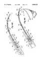
- FIG. 1is a perspective view of the microendoscope used in conjunction with the surgical devices and methods of this invention
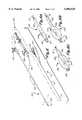
- FIG. 2is an enlarged fragmentary exploded perspective view illustrating the major components of the microendoscope
- FIG. 3Bis a perspective view of a patient undergoing a surgical procedure to remove a foreign object such as a coin from the patient's lungs or trachea by use of the Jackson grasping forceps with imaging capability.
- FIG. 4Bis another fragmentary perspective view of the microendoscope used in conjunction with the stent placement catheter wherein the stent placement catheter has been positioned within a desired location within the patient's body and the stent has been activated to allow removal of the catheter and microendoscope;
- FIG. 5Ais a greatly enlarged fragmentary perspective view of the microendoscope used in conjunction with an over-tube tissue separating device
- FIG. 6is a perspective, exploded view of a balloon catheter and the microendoscope prior to its insertion within the catheter;
- FIG. 6Ais a fragmentary perspective view of the balloon catheter with the microendoscope inserted therethrough prior to inflation of the balloon portion;
- FIGS. 1, 2 and 2Aillustrate a microendoscope that may be used with any number of different standard sized surgical instruments.
- the microendoscope 10includes a sheath 12 which receives and retains therein imaging elements.
- the imaging elementscomprise an imaging sensor or chip such as a CMOS or CCD-type which may be small as 0.50 mm.
- the size of the CMOS or CCD-type sensormay be varied. For most purposes, although the chip may be made as small as 0.50 mm in diameter, the optimal size would be between 2 to 4 mm with an upper range being from 6 to 10 mm. For most applications, the CMOS-type imaging sensor is more desirable since it can be made in any desired shape.
- CMOS-type imaging sensordesirable specifications for this type of imaging sensor would include a CMOS color imager having an array of pixels of 450 ⁇ 350, a spectral response of 350 nanometers to 800 nanometers, a resolution of more than 350 television lines at center, and a minimum illumination of 8 lux at f1.4.
- Some manufacturers which can provide such a CMOS-type imaging sensorinclude companies such as VLSI, Inc. of Scotland, Vision, Inc. of San Jose, Calif., Photobit, Inc. of La Crescenta, Calif., and i.e.t., Inc. of Cicero, N.Y.
- the imaging chip or sensor 16communicates with a miniature circuit board 14 by means of wires or other appropriate conducting means.
- the circuit boardinterprets the images transmitted by the imaging chip, or otherwise conditions the imaging signals so that such signals may be received and viewed on the video control unit 29 via wires or cable 19.
- FIG. 2illustrates the use of one circuit board, it will be understood that a series of circuit boards could be used in order to condition or otherwise manipulate the imaging signals produced by the imaging sensor. Regardless of the number of circuit boards used, they are connected to each other by a series of wire type of conductors or cables which are able to transmit the electronic signals from board to board or from the imaging sensor to the board, if only one board is used.
- the circuitry in these very small circuit boardscan be manufactured to condition the imaging signals produced by the imaging sensors in order to produce the desired visual output on a monitor screen, or may otherwise condition the imaging signals so that they can be recorded in a desired format such as on a compact disk or the like.
- the distal end 21 of the microendoscopemay be equipped with a desired lens system 20 in order that the surgical area under investigation may be magnified or otherwise conditioned prior to images of the area being received by the chip 16.
- a window 25may be used to seal the distal end of the microendoscope.
- the lens system 20may be movable in front of the imaging sensor, or the imaging sensor 16 and lens system 20 may be bonded together. In either case, the imaging sensor 16 and the lens system 20 are held in a fixed relationship with respect to one another by an outer plastic or metal tube (not shown) which fits over the lens system 20 and the imaging sensor 16.
- This outer plastic or metal tubemay be made of such a diameter or shape that it creates a tight friction fit in holding the lens system 20 and imaging system 16 in place.
- the chip and lensmay also be bonded in place inside the metal or plastic tube by an appropriate adhesive.
- the proximal end 23 of the microendoscope 10may be split into two separate branches and be further equipped in one branch with a video connector 24 which may connect directly to the mother circuit board or corresponding port of a video control unit 29 such as a laptop computer, and the other branch may receive fitting 22 which connects directly to a source of light 28.
- a video connector 24which may connect directly to the mother circuit board or corresponding port of a video control unit 29 such as a laptop computer
- the other branchmay receive fitting 22 which connects directly to a source of light 28.
- One section of the sheath 12could be made sterile and have a sufficient length which enabled it to extend out of the sterile field of the surgical area and then connect to the appropriate video control or light sources.
- the sheath 12can be made of a rigid material such as stainless steel, aluminum, or rigid plastic tubing made by companies such as the Polygon Company of Walkerton, Ind.
- a plurality of longitudinal channels 26may be integrally formed within and around the circumference of the sheath 12 which receives a plurality of light fibers 27.
- the light fibers 27may extend from fitting 22 all the way to the distal end 21 of the microendoscope in order that the surgical area under investigation may be illuminated. Even with the addition of the longitudinal channels containing the light fibers, the overall diameter D of the microendoscope may be maintained as small as 1 mm.
- other devices or materialsmay be passed through these small lumens or channels 26.
- laser fibers, guide wires, or metallic shaping wirescan be placed therein.
- Malleable wiressuch as shaping wires may be used in an instance where it is desired to form the microendoscope into a particular shape prior to insertion within a bodily opening. This "shaping" of the endoscope may be particularly useful in the visually aided placement of a device such as an endo-tracheal tube.
- the main channel or lumen of the sheath which receives the components of the microendoscopeis sealed or bonded to such components so that fluids will not be able to contact the various sensitive electronic elements.
- an appropriate epoxycan be used to seal the lens system 20 with respect to the interior sides of the sheath which form the main channel or lumen.
- the sheath 12may be include a braided metal layer (not shown) which effectively shields the electronic components within the sheath from static electricity or other electromagnetic disruptions.
- This composite sheath or tube protected from staticis commonly known in the art as a braided shielded cable.
- This braided layermay be formed interiorly or exteriorly of the channels 26.
- circuit board 14is illustrated as being inserted within the microendoscope, it shall be understood that the circuit board may be placed within the video control unit 29 or within the video connector 24. In such a circumstance, wires or conductors 18 can be extended the necessary length to link up with the circuit board 14 wherever its particular location. In addition to light fibers 27, fluid or gas can be introduced through one or more of the channels 26 in order to flush or otherwise clear the surgical area.
- One method to securely affix the lens system 20 to the sheath, which in turn stabilizes the adjacent electronic components within the sheath,is to drill a plurality of small holes (not shown) within the proximal end of the terminal window 25 which match the spacing and arrangement of longitudinal channels 26.
- the light fibersare then inserted through the longitudinal channels and into the small holes formed on the terminal window 25.
- the distal ends of the light fibers 26are then secured within the holes in the terminal window 25. This traversal of the light fibers actually into the terminal window 25 provides greater strength with respect to the attachment between the sheath and terminal window 25.
- one or more of metal wirescan be placed within one of the channels 26 and inserted within one of the small holes of the terminal window 25 in order to further provide a strong interlock between the sheath 12 and the terminal window 25.
- a thin-walled drape(not shown) could be used which is sterile and covers any exposed wiring or cables which are attached to the sheath and which may be in the sterile field.
- a drapewhich isolates nonsterile components from the sterile field.
- the microendoscope 10will now be described as it is used within a number of differing type of surgical instruments which do not have their own integral imaging capabilities.
- FIGS. 3A and 3BThe first application of the microendoscope is illustrated in FIGS. 3A and 3B.
- the microendoscope 10may be used with modified Jackson grasping forceps 30.
- the particular grasping forceps 30 illustrated in FIG. 3Ais characterized by an instrument channel 32 which may receive therethrough a pair of elongate grasping tines 34.
- the grasping tines 34terminate at the proximal end by forming a single tine rod 35.
- Grasping tines 34may be slid inwardly or outwardly within instrument channel 32 by the scissor action of first member 40 and second member 42.
- the first and second members 40 and 42connect at pivot point 44.
- the distal end of second member 42includes a push link 46 attached thereto at one end by means of pin 50.
- first member 40will cause the grasping tines 34 to be moved in a rearward or proximal direction such that the normally separated or open distal ends of tines 34 are pressed or drawn together by their proximal movement into the instrument channel 32.
- rings 56 and 58are again separated.
- the forcepsare able to grasp a foreign object by the open-close action of the tines 34.
- tightening knob 54may be provided so that first member 40 may be positioned at a desired location along tine rod 35. The particular positioning of first member 40 along tine rod 35 enables the grasping tines 34 to protrude a desired distance beyond the distal end of instrument channel 32.
- the grasping forceps 30are modified to include an endoscope tube 36 which receives the microendoscope 10.
- the tube 36may be welded or glued alongside channel 32, or attached by other well-known means.
- the endoscope tube 36may include a tightening knob or adjustment member 38 to control the extent to which the distal end 21 of the endoscope 10 protrudes beyond the distal end of the endoscope tube 36.
- Placement of the microendoscope directly alongside the forcepsenables the microendoscope to view the tines as they are manipulated to grasp the foreign object.
- the forward or distal placement of the microendoscopealso enables it to view the path of insertion into the patient.
- the Jackson grasping forcepsare inserted into the patient P to remove a foreign object O which can be viewed on the screen of the video control device 29.
- a foreign objectsuch as a coin may be removed from the lungs or trachea of the patient P by means of the Jackson grasping forceps 30.
- an instrumentsuch as a full-sized Jackson grasping forceps could not be introduced simultaneously with an endoscope because the trachea or throat of the patient could not accommodate the simultaneous introduction of both the forceps and the endoscope.
- the Jackson grasping deviceis the preferred surgical instrument since large objects such as coins require removal by tines of substantial size and strength as found only with such forceps. In other words, smaller forceps which may be introduced through a channel of standard endoscopes do not have the grasping strength or size to hold a relatively large foreign object such as a coin.
- FIGS. 4A and 4Billustrate the microendoscope 10 being used in conjunction with a stent placement catheter 90.
- a stent placement catheter assembly 90may include a catheter tube 92 which is used to transfer a stent coil 94 to the blockage B.
- the stent coil 94is wrapped around the exterior walls of the catheter tube 92.
- a pair of control wires 96 and 98may connect to the opposite ends of the stent coil 94 at junctions 100 and 102, respectively.
- Retainers 99may be used to secure the control wires 96 and 98 to the catheter tube 92.
- channelsformed within the walls of the tube 92 may be used to secure the control wires.
- the small size of many arteries Aprevented the introduction of an endoscope within the artery itself. Accordingly, exact placement of the stent 94 as viewed within the artery was not possible. Because of the small size of the microendoscope 10, it can be placed inside the catheter tube 92 so to provide the surgeon a view of the interior wall of the artery.
- the distal end 21 of the microendoscopemay protrude beyond the distal end of the catheter tube 92 in order to provide an image to the surgeon as the stent placement catheter is traversed through the artery or other bodily passages on the route to the artery.
- the microendoscopemay be removed from within the stent placement catheter and the stent coil may be activated to dilate the blockage B.
- One popular procedure for activating the stent coil 94is to make the stent from a material such as Nitronol which will remain expanded when activated within the body. Nitronol is a material which is very sensitive to changes in temperature.
- a low electric currentmay be introduced through the first and second control wires 96 and 98 in order to heat and, therefore, activate the stent coil 94 so that it uncoils or unravels within the blockage B. Furthermore, the electric current introduced through control wires 96 and 98 will cause the forked ends of junctions 100 and 102 to open thus enabling the control wires to be separated from the opposite ends of the stent coil 94.
- FIG. 4Billustrates the control wires 96 and 98 being removed after the appropriate electric current has expanded the stent coil 94 and has caused the release of junctions 100 and 102 from the opposite ends of the stent coil 94. After the stent coil has been activated, the catheter may be placed adjacent the coil and the microendoscope may again protrude from the distal end of the catheter enabling the microendoscope to again view the stent to ensure its proper placement.
- FIGS. 5A and 5Billustrate another application of the microendoscope 10 with a surgical instrument.
- a very small diameter over-tube tissue separating device 104is provided which is characterized by a guide tube 106 which receives the microendoscope.
- An extension 107is formed on the distal end of the guide tube 106 to provide a desired separation between the microendoscope 10 and a tissue contacting member.
- the tissue contacting memberis in the form of a separating bead 108.
- the microendoscopemay be introduced into a bodily passage simultaneously with the over-tube separator 104 wherein the separating bead 108 can separate linings of tissue or other discrete delineations between tissue types so that a subsequent surgical procedure can take place at the location of the separated tissues. Because of the extremely small size of the microendoscope, the separating bead 108 can be used in the most delicate separating procedures.
- the guide tube 106is preferably rigid and may extend any desired length depending upon the particular bodily passage within which the separator 104 is to be introduced.
- FIG. 5Billustrates one modification of the over-tube separator 104.
- the over-tube devicemay take the form of an over-tube dissector 110 which also includes a guide tube 112 and an extension 113.
- the extension 113may have attached thereto a dissecting hook 116 which can be used to separate, cut, or otherwise manipulate tissue in a desired location.
- the distal end of the microendoscope 21may protrude beyond the distal end of the guide tube 112.
- an adequate visual image of the area under investigationmay be achieved by having the distal end of the microendoscope 21 positioned flush with the distal end of the guide tube 106.
- the over-tube dissectorcould also include an electrode positioned adjacent to or in lieu of the separating bead 108 or hook 116. Such an electrode could be charged with an electric current to fulgerate tissue at a desired area.
- the microendoscope 10may be used in conjunction with a balloon catheter 120.
- the balloon catheter 120 shown in FIG. 6is of a type used within very small bodily passages such as the urethra or the like.
- the balloon catheter 120may include an elongate guide tube 122 having a distal end 123 which may be non-steerable, or steerable by guide wires (not shown) and a steering unit (not shown) which controls the guide wires as understood by those skilled in the art.
- the free or proximal end of air inflation port 124connects to stop cock 128 which in turn connects to syringe 130.
- a very small diameter air inflation line(not shown) may be formed interiorly of guide tube 122 and connect between port 124 and openings 134.
- stop cock 128may be positioned to prevent the back flow of air into the syringe 130 thus keeping the balloon inflated.
- guide tube 122may further include its own stop cock 126 positioned at the proximal end thereof in order that the guide tube 122 may also introduce liquids or gas simultaneously with the endoscope. Supply tubes (not shown) can supply the appropriate liquids or gas through stop cock 126.
- the microendoscope 10is inserted through the guide tube 122.
- the distal end 21 of the microendoscopemay protrude beyond the distal end 123 of the guide tube 122 as shown in FIG. 6A.
- the catheteris then inserted into the body of a patient.
- the microendoscope 10can provide a continuous image of the path of traversal.
- balloon 136may be inflated as illustrated in FIG. 6B.
- the microendoscopemay then be withdrawn back through the guide tube 122.
- the desired surgical proceduremay then take place by the introduction of a desired instrument through the guide tube 122.
Landscapes
- Health & Medical Sciences (AREA)
- Life Sciences & Earth Sciences (AREA)
- Surgery (AREA)
- Nuclear Medicine, Radiotherapy & Molecular Imaging (AREA)
- Biomedical Technology (AREA)
- Optics & Photonics (AREA)
- Pathology (AREA)
- Radiology & Medical Imaging (AREA)
- Biophysics (AREA)
- Engineering & Computer Science (AREA)
- Physics & Mathematics (AREA)
- Heart & Thoracic Surgery (AREA)
- Medical Informatics (AREA)
- Molecular Biology (AREA)
- Animal Behavior & Ethology (AREA)
- General Health & Medical Sciences (AREA)
- Public Health (AREA)
- Veterinary Medicine (AREA)
- Endoscopes (AREA)
Abstract
Description
This invention relates to surgical devices with removable imaging capability and methods of using the same, and more particularly, a microendoscope which may be used in conjunction with traditional surgical instruments which do not have their own integral imaging capability, and methods of employing such a microendoscope in various surgical procedures.
In recent years, the popularity of endoscopic surgery has proliferated. In fact, it may be accurate to say that endoscopic surgery is now the accepted medical standard for performing many surgical procedures which in past years were not traditionally conducted with endoscopic instruments. A major advantage of endoscopic surgery is that it creates much less trauma for the patient than traditional surgical techniques which required direct visual observation of the site under investigation by the surgeon. Advances have occurred in the electronic industry which allow smaller and smaller endoscopes to be used, thereby permitting endoscopic procedures to be undertaken in a less invasive manner then was previously possible. Also, improved circuitry and optics technology has resulted in enhanced visual imagery by the smaller endoscopes.
However, because of the sophisticated optics and circuitry contained in modern endoscopes, they can be very expensive and difficult to maintain. Additionally, since the size of the endoscope is still a major concern in endoscopic procedures, standard surgical instruments must be modified to reduce their size in order that the instruments can be used simultaneously with the endoscope. For example, it is well-known in the art to provide a plurality of channels within or around the endoscope in order that miniature surgical instruments such as forceps or the like may be simultaneously introduced with the endoscope. Therefore, the construction of most prior art endoscopes begins first with consideration of the size of the endoscope, and then operative channels are formed within or around the endoscope so that the modified surgical instrument may be introduced simultaneously to the site under investigation.
Although great advances have been made in the electronic industry in terms of reducing the size of the imaging elements which are used within the endoscope, many endoscopes in use continue to be too large to conduct certain surgical procedures. Additionally, many surgical procedures cannot be effectively conducted with the miniaturized surgical instruments. Rather, a more fall size surgical instrument is still required. Furthermore, cost continues to be a prohibitive factor because the special surgical instruments must be manufactured which are small enough to fit within the small channels of the endoscope being used.
From the foregoing, it is apparent that an even smaller imaging device is desirable which can be used universally with larger and more standard sized surgical instruments in order to reduce the cost of providing endoscopic capability for certain surgical procedures as well as maintaining a minimally invasive sized instrument with imaging capability which is used to conduct such surgical procedures.
In accordance with the present invention, a microendoscope is provided which may be used with standard surgical instruments which are retrofitted to include a small tube or other means by which the microendoscope may be introduced simultaneously with the standard instruments. The microendoscope of this invention is so small that it by itself presents little or no problem in terms of being an overly invasive object introduced into the surgical area. The microendoscope of this invention can be manufactured with an overall diameter as little as 1 mm. The microendoscope is capable of being manufactured in such a small size by use of either a modified CCD chip or a CMOS-type imaging chip. These imaging chips communicate with circuitry in the form of a miniature circuit board which may be incorporated directly into the microendoscope, is or the circuitry can be located within the video control device remote from the microendoscope. The microendoscope may further include integral light means by which the surgical area under investigation may be illuminated.
In one application, the microendoscope of this invention may be used in conjunction with standard Jackson grasping forceps which have been modified to include a longitudinal tube or channel for which to receive the microendoscope. In use, the microendoscope provides an integral imaging capability while the surgeon manipulates the Jackson grasping forceps for removal of a foreign object within a patient.
In another application, the microendoscope may be used in conjunction with a stent placement catheter. In this application, the microendoscope is placed through the small diameter tube of the catheter to provide integral imaging capability for guiding the catheter to the precise location in the body at which the stent is to be positioned.
In yet another application, the microendoscope of this invention may be used in conjunction with an "over-tube" dissecting or tissue separating device in order to conduct very precise cutting, tissue separating or fulgeration procedures.
In another application, the microendoscope may be used in conjunction with a steerable balloon catheter in much the same manner as the microendoscope is used with the stent placement catheter.
The microendoscope may be sterilized or disinfected in any number of different protocols. The sheath of the microendoscope may be made of a material which can with stand the heat and pressure of an autoclave sterilizing protocol, as well as pure gas or liquid soaking sterilization protocols. Accordingly, the microendoscope may be used numerous times in any number of differing types of surgical instruments in differing kinds of surgical procedures after re-sterilization.
The sheath of the microendoscope also may be very flexible which enables the microendoscope to be twisted or bent in any desired configuration in order to conform to the particular path of the surgical instrument introduced within the patient's body.
These and other advantages will become apparent to those skilled in the art in view of the description of the drawings and the description of the preferred embodiments which follow.
FIG. 1 is a perspective view of the microendoscope used in conjunction with the surgical devices and methods of this invention,
FIG. 2 is an enlarged fragmentary exploded perspective view illustrating the major components of the microendoscope;
FIG. 2A is a longitudinal section taken alongline 2A--2A of FIG. 1 illustrating the arrangement of the major components within the microendoscope;
FIG. 3A is a perspective view of the microendoscope used in conjunction with Jackson grasping forceps;
FIG. 3B is a perspective view of a patient undergoing a surgical procedure to remove a foreign object such as a coin from the patient's lungs or trachea by use of the Jackson grasping forceps with imaging capability.
FIG. 4A is an enlarged fragmentary perspective view of the microendoscope used in conjunction with a stent placement catheter;
FIG. 4B is another fragmentary perspective view of the microendoscope used in conjunction with the stent placement catheter wherein the stent placement catheter has been positioned within a desired location within the patient's body and the stent has been activated to allow removal of the catheter and microendoscope;
FIG. 5A is a greatly enlarged fragmentary perspective view of the microendoscope used in conjunction with an over-tube tissue separating device;
FIG. 5B is a fragmentary perspective view of the microendoscope used in conjunction with an over tube dissecting device used for cutting tissue or ligation;
FIG. 6 is a perspective, exploded view of a balloon catheter and the microendoscope prior to its insertion within the catheter;
FIG. 6A is a fragmentary perspective view of the balloon catheter with the microendoscope inserted therethrough prior to inflation of the balloon portion;
FIG. 6B is another fragmentary perspective view of the microendoscope inserted through the balloon catheter after the balloon portion has inflated; and
FIG. 6C is yet another fragmentary perspective view as in FIGS. 6A and 6B illustrating the microendoscope being removed from within the balloon catheter.
FIGS. 1, 2 and 2A illustrate a microendoscope that may be used with any number of different standard sized surgical instruments. Themicroendoscope 10 includes asheath 12 which receives and retains therein imaging elements. The imaging elements comprise an imaging sensor or chip such as a CMOS or CCD-type which may be small as 0.50 mm. The size of the CMOS or CCD-type sensor may be varied. For most purposes, although the chip may be made as small as 0.50 mm in diameter, the optimal size would be between 2 to 4 mm with an upper range being from 6 to 10 mm. For most applications, the CMOS-type imaging sensor is more desirable since it can be made in any desired shape. This is because CCD devices have to be made either square or rectangular in shape because the information collected on the pixels of the CCD chip must be transferred and interpreted by the circuitry in a line-by-line fashion, versus a CMOS-type chip which can have its imaging data interpreted pixel by pixel. Typical specifications for the use a CCD-type chip would include one which is approximately 1/8 inch in size and contains an array of pixels of 640×480. In this array and chip size, the pixels would each be approximately 2.4×2.4 microns. One manufacturer for such a small CCD device is the Philips Imaging Technology Company from Eindoven, Netherlands. Other manufacturers which also provide such small type CCD imaging sensors are the Sony Corporation and Panasonic. For the CMOS-type imaging sensor, desirable specifications for this type of imaging sensor would include a CMOS color imager having an array of pixels of 450×350, a spectral response of 350 nanometers to 800 nanometers, a resolution of more than 350 television lines at center, and a minimum illumination of 8 lux at f1.4. Some manufacturers which can provide such a CMOS-type imaging sensor include companies such as VLSI, Inc. of Scotland, Vision, Inc. of San Jose, Calif., Photobit, Inc. of La Crescenta, Calif., and i.e.t., Inc. of Cicero, N.Y. The imaging chip orsensor 16 communicates with aminiature circuit board 14 by means of wires or other appropriate conducting means. The circuit board interprets the images transmitted by the imaging chip, or otherwise conditions the imaging signals so that such signals may be received and viewed on thevideo control unit 29 via wires orcable 19.
The imaging signals produced by theimaging sensor 16 can be either a digital or analog format. In many instances, the digital format is preferred since it provides the capability to better condition or manipulate the image viewed on a screen. For example, the digital format allows the creation of a number of functions for the image viewed on a screen. Functions such as automatic focus, automatic light control, automatic iris, automatic white balance, and digital recording on compact disks or D.V.D. recording systems are possible.
Although FIG. 2 illustrates the use of one circuit board, it will be understood that a series of circuit boards could be used in order to condition or otherwise manipulate the imaging signals produced by the imaging sensor. Regardless of the number of circuit boards used, they are connected to each other by a series of wire type of conductors or cables which are able to transmit the electronic signals from board to board or from the imaging sensor to the board, if only one board is used. The circuitry in these very small circuit boards can be manufactured to condition the imaging signals produced by the imaging sensors in order to produce the desired visual output on a monitor screen, or may otherwise condition the imaging signals so that they can be recorded in a desired format such as on a compact disk or the like.
Thedistal end 21 of the microendoscope may be equipped with a desiredlens system 20 in order that the surgical area under investigation may be magnified or otherwise conditioned prior to images of the area being received by thechip 16. In addition to or in lieu of alens system 20, awindow 25 may be used to seal the distal end of the microendoscope. Thelens system 20 may be movable in front of the imaging sensor, or theimaging sensor 16 andlens system 20 may be bonded together. In either case, theimaging sensor 16 and thelens system 20 are held in a fixed relationship with respect to one another by an outer plastic or metal tube (not shown) which fits over thelens system 20 and theimaging sensor 16. This outer plastic or metal tube may be made of such a diameter or shape that it creates a tight friction fit in holding thelens system 20 andimaging system 16 in place. Alternatively, the chip and lens may also be bonded in place inside the metal or plastic tube by an appropriate adhesive.
Theproximal end 23 of themicroendoscope 10 may be split into two separate branches and be further equipped in one branch with avideo connector 24 which may connect directly to the mother circuit board or corresponding port of avideo control unit 29 such as a laptop computer, and the other branch may receive fitting 22 which connects directly to a source oflight 28. There is essentially no limit as to the length of theflexible sheath 12. One section of thesheath 12 could be made sterile and have a sufficient length which enabled it to extend out of the sterile field of the surgical area and then connect to the appropriate video control or light sources. Thesheath 12 can be made of a rigid material such as stainless steel, aluminum, or rigid plastic tubing made by companies such as the Polygon Company of Walkerton, Ind. Polygon tubing is a material made of a composite plastic and is structurally as strong as many metal materials. Alternatively, the sheath may be made of plastics which are thin-walled and flexible. Using such a flexible material allows for the SASS microendoscope to be both flexible and steerable. Preferable materials for making the microendoscope flexible and steerable include various formulations of teflon®, polyethylene, and polypropylene. Furthermore, if thesheath 12 is made flexible, it can conform to the sharp turns and twists that it may encounter within the body on the path to the desired surgical site.
A plurality oflongitudinal channels 26 may be integrally formed within and around the circumference of thesheath 12 which receives a plurality oflight fibers 27. Thelight fibers 27 may extend from fitting 22 all the way to thedistal end 21 of the microendoscope in order that the surgical area under investigation may be illuminated. Even with the addition of the longitudinal channels containing the light fibers, the overall diameter D of the microendoscope may be maintained as small as 1 mm.
In addition tolight fibers 27, other devices or materials may be passed through these small lumens orchannels 26. For example, laser fibers, guide wires, or metallic shaping wires can be placed therein. Malleable wires such as shaping wires may be used in an instance where it is desired to form the microendoscope into a particular shape prior to insertion within a bodily opening. This "shaping" of the endoscope may be particularly useful in the visually aided placement of a device such as an endo-tracheal tube.
The main channel or lumen of the sheath which receives the components of the microendoscope is sealed or bonded to such components so that fluids will not be able to contact the various sensitive electronic elements. For example, an appropriate epoxy can be used to seal thelens system 20 with respect to the interior sides of the sheath which form the main channel or lumen. In addition to making the sheath watertight or fluid resistant, it is desirable to shield the interior electronic components from static or other disruptive electric signals. Therefore, thesheath 12 may be include a braided metal layer (not shown) which effectively shields the electronic components within the sheath from static electricity or other electromagnetic disruptions. This composite sheath or tube protected from static is commonly known in the art as a braided shielded cable. This braided layer may be formed interiorly or exteriorly of thechannels 26.
Although thecircuit board 14 is illustrated as being inserted within the microendoscope, it shall be understood that the circuit board may be placed within thevideo control unit 29 or within thevideo connector 24. In such a circumstance, wires orconductors 18 can be extended the necessary length to link up with thecircuit board 14 wherever its particular location. In addition tolight fibers 27, fluid or gas can be introduced through one or more of thechannels 26 in order to flush or otherwise clear the surgical area.
One method to securely affix thelens system 20 to the sheath, which in turn stabilizes the adjacent electronic components within the sheath, is to drill a plurality of small holes (not shown) within the proximal end of theterminal window 25 which match the spacing and arrangement oflongitudinal channels 26. The light fibers are then inserted through the longitudinal channels and into the small holes formed on theterminal window 25. The distal ends of thelight fibers 26 are then secured within the holes in theterminal window 25. This traversal of the light fibers actually into theterminal window 25 provides greater strength with respect to the attachment between the sheath andterminal window 25. Furthermore, one or more of metal wires can be placed within one of thechannels 26 and inserted within one of the small holes of theterminal window 25 in order to further provide a strong interlock between thesheath 12 and theterminal window 25.
In addition to providing a sterile sheath and extending the length ofsheath 12 to ensure that it extends away from the sterile field the desired length, a thin-walled drape (not shown) could be used which is sterile and covers any exposed wiring or cables which are attached to the sheath and which may be in the sterile field. Although not illustrated, it is well understood by those skilled in the art to use a drape which isolates nonsterile components from the sterile field.
Themicroendoscope 10 will now be described as it is used within a number of differing type of surgical instruments which do not have their own integral imaging capabilities.
The first application of the microendoscope is illustrated in FIGS. 3A and 3B. As shown, themicroendoscope 10 may be used with modifiedJackson grasping forceps 30. The particular graspingforceps 30 illustrated in FIG. 3A is characterized by aninstrument channel 32 which may receive therethrough a pair of elongate graspingtines 34. The graspingtines 34 terminate at the proximal end by forming asingle tine rod 35. Graspingtines 34 may be slid inwardly or outwardly withininstrument channel 32 by the scissor action offirst member 40 andsecond member 42. The first andsecond members pivot point 44. The distal end ofsecond member 42 includes apush link 46 attached thereto at one end by means ofpin 50. The other end ofpush link 46 is connected tobracket 48 by means ofpin 52. Asrings members first member 40 will cause the graspingtines 34 to be moved in a rearward or proximal direction such that the normally separated or open distal ends oftines 34 are pressed or drawn together by their proximal movement into theinstrument channel 32. When it is desired to have thetines 34 protrude from theinstrument channel 32, rings 56 and 58 are again separated. The forceps are able to grasp a foreign object by the open-close action of thetines 34. Conveniently, tighteningknob 54 may be provided so thatfirst member 40 may be positioned at a desired location alongtine rod 35. The particular positioning offirst member 40 alongtine rod 35 enables the graspingtines 34 to protrude a desired distance beyond the distal end ofinstrument channel 32.
The graspingforceps 30 are modified to include anendoscope tube 36 which receives themicroendoscope 10. Thetube 36 may be welded or glued alongsidechannel 32, or attached by other well-known means. Conveniently, theendoscope tube 36 may include a tightening knob oradjustment member 38 to control the extent to which thedistal end 21 of theendoscope 10 protrudes beyond the distal end of theendoscope tube 36. Placement of the microendoscope directly alongside the forceps enables the microendoscope to view the tines as they are manipulated to grasp the foreign object. The forward or distal placement of the microendoscope also enables it to view the path of insertion into the patient.
As shown in FIG. 3B, the Jackson grasping forceps are inserted into the patient P to remove a foreign object O which can be viewed on the screen of thevideo control device 29. From the surgery being performed in FIG. 3B, a foreign object such as a coin may be removed from the lungs or trachea of the patient P by means of theJackson grasping forceps 30. In the past, an instrument such as a full-sized Jackson grasping forceps could not be introduced simultaneously with an endoscope because the trachea or throat of the patient could not accommodate the simultaneous introduction of both the forceps and the endoscope. Therefore, this procedure previously had to be conducted without the surgeon being able to visualize the Jackson grasping forceps as it was introduced into and through the path in the patient's body prior to reaching the surgical site under investigation. Because of the small size of themicroendoscope 10, the addition ofendoscope tube 36 makes it possible for the Jackson grasping forceps to have the integral imaging capability. In the operation depicted in FIG. 3B, the Jackson grasping device is the preferred surgical instrument since large objects such as coins require removal by tines of substantial size and strength as found only with such forceps. In other words, smaller forceps which may be introduced through a channel of standard endoscopes do not have the grasping strength or size to hold a relatively large foreign object such as a coin.
FIGS. 4A and 4B illustrate themicroendoscope 10 being used in conjunction with astent placement catheter 90. One common procedure used to dilate or expand a blocked artery A is the introduction of a stent which is used to force open the blockage B. As shown in FIG. 4A, a stentplacement catheter assembly 90 may include acatheter tube 92 which is used to transfer astent coil 94 to the blockage B. Thestent coil 94 is wrapped around the exterior walls of thecatheter tube 92. A pair ofcontrol wires stent coil 94 atjunctions control wires catheter tube 92. Alternatively, channels (not shown) formed within the walls of thetube 92 may be used to secure the control wires. In prior procedures, the small size of many arteries A prevented the introduction of an endoscope within the artery itself. Accordingly, exact placement of thestent 94 as viewed within the artery was not possible. Because of the small size of themicroendoscope 10, it can be placed inside thecatheter tube 92 so to provide the surgeon a view of the interior wall of the artery.
In operation, thedistal end 21 of the microendoscope may protrude beyond the distal end of thecatheter tube 92 in order to provide an image to the surgeon as the stent placement catheter is traversed through the artery or other bodily passages on the route to the artery. As shown in FIG. 4B, once the stent placement catheter has been introduced into the blockage B, the microendoscope may be removed from within the stent placement catheter and the stent coil may be activated to dilate the blockage B. One popular procedure for activating thestent coil 94 is to make the stent from a material such as Nitronol which will remain expanded when activated within the body. Nitronol is a material which is very sensitive to changes in temperature. A low electric current may be introduced through the first andsecond control wires stent coil 94 so that it uncoils or unravels within the blockage B. Furthermore, the electric current introduced throughcontrol wires junctions stent coil 94. FIG. 4B illustrates thecontrol wires stent coil 94 and has caused the release ofjunctions stent coil 94. After the stent coil has been activated, the catheter may be placed adjacent the coil and the microendoscope may again protrude from the distal end of the catheter enabling the microendoscope to again view the stent to ensure its proper placement.
FIGS. 5A and 5B illustrate another application of themicroendoscope 10 with a surgical instrument. As shown in FIG. 5A, a very small diameter over-tubetissue separating device 104 is provided which is characterized by aguide tube 106 which receives the microendoscope. Anextension 107 is formed on the distal end of theguide tube 106 to provide a desired separation between themicroendoscope 10 and a tissue contacting member. In FIG. 5A, the tissue contacting member is in the form of a separating bead 108. In use, the microendoscope may be introduced into a bodily passage simultaneously with theover-tube separator 104 wherein the separating bead 108 can separate linings of tissue or other discrete delineations between tissue types so that a subsequent surgical procedure can take place at the location of the separated tissues. Because of the extremely small size of the microendoscope, the separating bead 108 can be used in the most delicate separating procedures. Theguide tube 106 is preferably rigid and may extend any desired length depending upon the particular bodily passage within which theseparator 104 is to be introduced.
FIG. 5B illustrates one modification of theover-tube separator 104. As shown in FIG. 5B, the over-tube device may take the form of anover-tube dissector 110 which also includes aguide tube 112 and anextension 113. In lieu of the separating bead 108, theextension 113 may have attached thereto adissecting hook 116 which can be used to separate, cut, or otherwise manipulate tissue in a desired location. As further shown in FIG. 5B, the distal end of themicroendoscope 21 may protrude beyond the distal end of theguide tube 112. Alternatively, as shown in FIG. 5A, an adequate visual image of the area under investigation may be achieved by having the distal end of themicroendoscope 21 positioned flush with the distal end of theguide tube 106. Although not illustrated, the over-tube dissector could also include an electrode positioned adjacent to or in lieu of the separating bead 108 orhook 116. Such an electrode could be charged with an electric current to fulgerate tissue at a desired area.
In yet another application, themicroendoscope 10 may be used in conjunction with aballoon catheter 120. Theballoon catheter 120 shown in FIG. 6 is of a type used within very small bodily passages such as the urethra or the like. Theballoon catheter 120 may include anelongate guide tube 122 having adistal end 123 which may be non-steerable, or steerable by guide wires (not shown) and a steering unit (not shown) which controls the guide wires as understood by those skilled in the art. The free or proximal end ofair inflation port 124 connects to stopcock 128 which in turn connects tosyringe 130. A very small diameter air inflation line (not shown) may be formed interiorly ofguide tube 122 and connect betweenport 124 andopenings 134. When theplunger 132 of the syringe is depressed, air is forced throughair inflation port 124, through the small inflation line (not shown) and throughopenings 134 to inflate theballoon 136. Stopcock 128 may be positioned to prevent the back flow of air into thesyringe 130 thus keeping the balloon inflated. As also shown in FIG. 6, guidetube 122 may further include itsown stop cock 126 positioned at the proximal end thereof in order that theguide tube 122 may also introduce liquids or gas simultaneously with the endoscope. Supply tubes (not shown) can supply the appropriate liquids or gas throughstop cock 126.
The sequential operation of the balloon catheter will now be explained with reference to FIGS. 6A-6C. First, themicroendoscope 10 is inserted through theguide tube 122. Thedistal end 21 of the microendoscope may protrude beyond thedistal end 123 of theguide tube 122 as shown in FIG. 6A. The catheter is then inserted into the body of a patient. As the balloon catheter is traversed through the desired bodily passage, themicroendoscope 10 can provide a continuous image of the path of traversal. When the distal end of the balloon catheter reaches its desired destination,balloon 136 may be inflated as illustrated in FIG. 6B. As shown in FIG. 6C, the microendoscope may then be withdrawn back through theguide tube 122. The desired surgical procedure may then take place by the introduction of a desired instrument through theguide tube 122.
By the foregoing, it is apparent that many surgical procedures can be enhanced by the use of a very small microendoscope which provides an integral imaging capability to the surgeon. Relatively large surgical instruments such as Jackson grasping forceps may be provided with their own integral imaging capability by the attachment of the microendoscope. The introduction of stents into arteries may now be achieved with direct view of the blockage by the microendoscope which is introduced simultaneously with the catheter. In procedures where tissue must be separated or dissected, very precise tissue manipulation can occur by use of an over-tube device which is placed directly over the microendoscope. In yet another application, the use of a balloon catheter may be enhanced by the microendoscope which is again introduced simultaneously with the catheter.
This invention has been described in detail with reference to particular embodiments thereof, but it will be understood that various other modifications can be effected within the spirit and scope of this invention.
Claims (19)
1. A surgical device with removable imaging capability for use at a surgical site, said surgical device comprising:
a microendoscope including an elongate sheath having a peripheral wall and a central passageway formed therethrough, an imaging sensor placed within said central passageway at a distal end of said sheath, circuitry means placed adjacent said imaging sensor at said distal end and extending along said central passageway such that said circuitry means does not extend circumferentially beyond said imaging sensor, conducting means interconnecting said imaging sensor to said circuitry means for transferring electrical signals from said imaging sensor to said circuitry means, and a conductor interconnecting said circuitry means for providing a video ready signal to a video control device which enables a viewer to view visual images captured by said imaging sensor of the surgical site;
grasping forceps including an instrument channel having a central opening formed therethrough, grasping tines having proximal ends connected to one another and distal ends spaced apart a desired distance, said proximal ends being inserted through said central opening, a first member having a distal end attached to said proximal ends of said grasping tines, a second member having a distal end attached to said instrument channel and said second member being pivotally connected to said first member, said first member being movable with respect to said second member to move said grasping tines longitudinally within said instrument channel to cause said distal ends of said grasping tines to be pressed together when entering said central opening or to be spaced apart when exiting said central opening; and
an endoscope tube attached exteriorly of said instrument channel for receiving said microendoscope such that said microendoscope may provide a visual image as said grasping forceps are manipulated within the body of a patient.
2. A device, as claimed in claim 1, farther including:
a lens within said passageway of said elongate sheath to condition the image of the surgical site prior to being received by said imaging sensor.
3. A device, as claimed in claim 1, further including:
a plurality of longitudinal channels formed within said peripheral wall of said elongate sheath; and
at least one light fiber in one of said plurality of longitudinal channels and extending to said distal end of said elongate sheath, said light fiber communicating with a source of light to illuminate the surgical area under observation.
4. A surgical device with removable imaging capability for use at a surgical site, said surgical device comprising:
a microendoscope including an elongate sheath having a peripheral wall and a central passageway formed therethrough, an imaging sensor placed within said central passageway at a distal end of said sheath, processor circuitry means placed adjacent said imaging sensor at said distal end and extending along said central passageway such that said circuitry means does not extend circumferentially beyond said imaging sensor, conducting means interconnecting said imaging sensor to said processor circuitry means for transferring electrical signals from said imaging sensor to said processor circuitry means, and a conductor directly interconnecting said processor circuitry means for providing a video ready signal to a video control device which enables a viewer to view visual images captured by said imaging sensor of the surgical site; and
a stent placement catheter including a tube having a central opening formed therethrough, a stent coil positioned at a distal end of said tube and exteriorly thereof, at least one control wire connected to said stent coil, said at least one control wire extending longitudinally along said tube, said microendoscope being insertable through said central opening such that said microendoscope may provide a visual image as said catheter is manipulated within the body of a patient.
5. A device, as claimed in claim 4, further including:
a lens within said passageway of said elongate sheath to condition the image of the surgical site prior to being received by said imaging sensor.
6. A device, as claimed in claim 4, further including:
a plurality of longitudinal channels formed within said peripheral wall of said elongate sheath; and
at least one light fiber in one of said plurality of longitudinal channels and extending to said distal end of said elongate sheath, said light fiber communicating with a source of light to illuminate the surgical area under observation.
7. A surgical device with removable imaging capability for use at a surgical site, said surgical device comprising:
a microendoscope including an elongate sheath having a peripheral wall and a central passageway formed therethrough, an imaging sensor placed within said central passageway at a distal end of said sheath, circuitry means placed adjacent said imaging sensor at said distal end and extending along said central passageway such that said circuitry means does not extend circumferentially beyond said imaging sensor, conducting means interconnecting said imaging sensor to said circuitry means for transferring electrical signals from said imaging sensor to said circuitry means, and a conductor interconnecting said circuitry means for providing a video ready signal to a video control device which enables a viewer to view visual images captured by said imaging sensor of the surgical site; and
an over-tube device including a guide tube having a central opening formed therethrough, an extension connected to a distal end of said over-tube device and extending distally thereof, and a tissue contacting member attached to said extension for manipulating the tissue of a patient, said microendoscope being insertable through said central opening enabling said microendoscope to view said tissue contacting member and the surrounding surgical area as tissue manipulation occurs.
8. A device, as claimed in claim 7, further including:
a lens within said passageway of said elongate sheath to condition the image of the surgical site prior to being received by said imaging sensor.
9. A device, as claimed in claim 7, further including:
a plurality of longitudinal channels formed within said peripheral wall of said elongate sheath; and
at least one light fiber in one of said plurality of longitudinal channels and extending to said distal end of said elongate sheath, said light fiber communicating with a source of light to illuminate the surgical area under observation.
10. A device, as claimed in claim 7, wherein said tissue contacting member is a separating bead having a spherical shape especially adapted for tissue separation.
11. A device, as claimed in claim 7, wherein said tissue contacting member is a hook-shaped structure enabling tissue cutting.
12. A surgical device with removable imaging capability for use at a surgical site, said surgical device comprising:
a microendoscope including an elongate sheath having a peripheral wall and a central passageway formed therethrough, an imaging sensor placed within said central passageway at a distal end of said sheath, processor circuitry means placed adjacent said imaging sensor at said distal end and extending along said central passageway such that said circuitry means does not extend circumferentially beyond said imaging sensor, conducting means interconnecting said imaging sensor to said processor circuitry means for transferring electrical signals from said imaging sensor to said processor circuitry means, and a conductor directly interconnecting said processor circuitry means for providing a video ready signal to a video control device which enables a viewer to view visual images captured by said imaging sensor of the surgical site; and
a balloon catheter including a guide tube having a distal end, a periphery, and a central opening formed therethrough, a balloon attached around said distal end and said periphery of said guide tube, at least one hole formed through said distal end of said guide tube, a means to introduce gas through said at least one hole, said introducing means communicating with a source of air to inflate said balloon, wherein said microendoscope is insertable through said central opening to enable the microendoscope to provide a visual image as said balloon catheter is manipulated within the body of a patient.
13. A device, as claimed in claim 12, further including:
a lens within said passageway of said elongate sheath to condition the image of the surgical site prior to being received by said imaging sensor.
14. A device, as claimed in claim 12, further including:
a plurality of longitudinal channels formed within said peripheral wall of said elongate sheath; and
at least one light fiber in one of said plurality of longitudinal channels and extending to said distal end of said elongate sheath, said light fiber communicating with a source of light to illuminate the surgical area under observation.
15. A device, as claimed in claim 12, further including:
a stop cock placed in line with said introducing means to control flow of air through said at least one hole.
16. A method of placing a stent at a desired site within the body of a patient, said method comprising the steps of:
providing a catheter including a central opening and a stent attached at the distal end of the catheter;
inserting a microendoscope through the central opening of the catheter, said microendoscope including an elongate sheath having a peripheral wall and a central passageway formed therethrough, an imaging sensor placed within said central passageway at a distal end of said sheath, processor circuitry means placed adjacent said imaging sensor at said distal end and extending along said central passageway such that said circuitry means does not extend circumferentially beyond said imaging sensor, conducting means interconnecting said imaging sensor to said processor circuitry means for transferring electrical signals from said imaging sensor to said processor circuitry means, and a conductor directly interconnecting said processor circuitry means for providing a video ready signal to a video control device which enables a viewer to view visual images captured by said imaging sensor of the surgical site;
inserting the catheter containing the microendoscope into the body of a patient;
viewing the body of the patient by images produced from the microendoscope as the catheter is moved therethrough;
locating the desired site to which the stent is to be placed by means of the images produced from the microendoscope;
activating the stent at the desired site; and
withdrawing the catheter and microendoscope from within the body of the patient.
17. A method, as claimed in claim 16, further including the step of:
recording the images produced from the microendoscope by means of a computer.
18. A method of placing a balloon catheter at a desired location within the body of a patient, said method comprising the steps of:
providing a catheter having a central opening and a balloon attached to a distal end of the catheter;
inserting a microendoscope through the central opening of the catheter, said microendoscope including an elongate sheath having a peripheral wall and a central passageway formed therethrough, an imaging sensor placed within said central passageway at a distal end of said sheath, processor circuitry means placed adjacent said imaging sensor at said distal end and extending along said central passageway such that said circuitry means does not extend circumferentially beyond said imaging sensor, conducting means interconnecting said imaging sensor to said processor circuitry means for transferring electrical signals from said imaging sensor to said processor circuitry means and a conductor directly interconnecting said processor circuitry means for providing a video ready signal to a video control device which enables a viewer to view visual images captured by said imaging sensor of the surgical site;
inserting the catheter containing the microendoscope within the body of the patient;
viewing the body of the patient as the catheter is moved through the body by means of visual images produced from the microendoscope;
locating the desired surgical area by means of the images produced from the microendoscope;
activating the balloon of the balloon catheter within a bodily passage of the patient at the desired surgical area;
withdrawing the microendoscope from within the central opening of the balloon catheter; and
introducing a surgical instrument through the central opening of the balloon catheter and to the desired surgical area to conduct a surgical procedure.
19. A method, as claimed in claim 18, further including the step of:
recording the images produced from the microendoscope by means of a computer.
Priority Applications (2)
| Application Number | Priority Date | Filing Date | Title |
|---|---|---|---|
| US08/927,785US6086528A (en) | 1997-09-11 | 1997-09-11 | Surgical devices with removable imaging capability and methods of employing same |
| US09/544,528US6211904B1 (en) | 1997-09-11 | 2000-04-06 | Surgical devices incorporating reduced area imaging devices |
Applications Claiming Priority (1)
| Application Number | Priority Date | Filing Date | Title |
|---|---|---|---|
| US08/927,785US6086528A (en) | 1997-09-11 | 1997-09-11 | Surgical devices with removable imaging capability and methods of employing same |
Related Child Applications (1)
| Application Number | Title | Priority Date | Filing Date |
|---|---|---|---|
| US08/944,322Continuation-In-PartUS5929901A (en) | 1997-09-11 | 1997-10-06 | Reduced area imaging devices incorporated within surgical instruments |
Publications (1)
| Publication Number | Publication Date |
|---|---|
| US6086528Atrue US6086528A (en) | 2000-07-11 |
Family
ID=25455253
Family Applications (1)
| Application Number | Title | Priority Date | Filing Date |
|---|---|---|---|
| US08/927,785Expired - Fee RelatedUS6086528A (en) | 1997-09-11 | 1997-09-11 | Surgical devices with removable imaging capability and methods of employing same |
Country Status (1)
| Country | Link |
|---|---|
| US (1) | US6086528A (en) |
Cited By (148)
| Publication number | Priority date | Publication date | Assignee | Title |
|---|---|---|---|---|
| US20010016804A1 (en)* | 1996-09-04 | 2001-08-23 | Cunningham Richard L. | Surgical simulation interface device and method |
| US6387043B1 (en)* | 1998-05-13 | 2002-05-14 | Inbae Yoon | Penetrating endoscope and endoscopic surgical instrument with CMOS image sensor and display |
| US6419626B1 (en)* | 1998-08-12 | 2002-07-16 | Inbae Yoon | Surgical instrument endoscope with CMOS image sensor and physical parameter sensor |
| US20020165444A1 (en)* | 2001-04-20 | 2002-11-07 | Whitman Michael P. | Imaging device |
| US20020173786A1 (en)* | 2001-05-21 | 2002-11-21 | Kortenbach Juergen A. | Methods and apparatus for on-endoscope instruments having end effectors and combinations of on-endoscope and through-endoscope instruments |
| US6506150B1 (en)* | 1999-04-13 | 2003-01-14 | Pentax Corporation | Self-retaining endoscope |
| WO2002047541A3 (en)* | 2000-12-15 | 2003-01-23 | Amir Belson | Obstetrical imaging system and integrated fetal vacuum extraction system |
| US6517530B1 (en)* | 1996-11-08 | 2003-02-11 | Leiv Eiriksson Nyfotek As | Probe device |
| US6599237B1 (en)* | 2000-01-10 | 2003-07-29 | Errol O. Singh | Instrument and method for facilitating endoscopic examination and surgical procedures |
| US20030176794A1 (en)* | 2002-01-30 | 2003-09-18 | Whitman Michael P. | Surgical imaging device |
| US20030233092A1 (en)* | 2000-12-06 | 2003-12-18 | Kortenbach Juergen A. | Methods and apparatus for the treatment of gastric ulcers |
| WO2002055126A3 (en)* | 2001-01-11 | 2004-01-15 | Given Imaging Ltd | Device and system for in-vivo procedures |
| US6685716B1 (en)* | 2000-01-04 | 2004-02-03 | Transvascular, Inc. | Over-the-wire apparatus and method for open surgery making of fluid connection between two neighboring vessels |
| US20040076940A1 (en)* | 1998-01-28 | 2004-04-22 | Immersion Medical, Inc. | Interface device and method for interfacing instruments to medical procedure simulation systems |
| US20040093056A1 (en)* | 2002-10-26 | 2004-05-13 | Johnson Lianw M. | Medical appliance delivery apparatus and method of use |
| US6736828B1 (en)* | 2000-09-29 | 2004-05-18 | Scimed Life Systems, Inc. | Method for performing endoluminal fundoplication and apparatus for use in the method |
| US20040193243A1 (en)* | 2003-03-31 | 2004-09-30 | Mangiardi Eric K. | Medical appliance optical delivery and deployment apparatus and method |
| US20050010138A1 (en)* | 2003-07-11 | 2005-01-13 | Mangiardi Eric K. | Lumen-measuring devices and method |
| US20050049509A1 (en)* | 2003-08-28 | 2005-03-03 | Mansour Hebah Noshy | Cervix monitoring system and related devices and methods |
| US6879851B2 (en) | 2001-06-07 | 2005-04-12 | Lightlab Imaging, Llc | Fiber optic endoscopic gastrointestinal probe |
| US20050283048A1 (en)* | 2001-10-19 | 2005-12-22 | Visionscope, Llc | Portable imaging system employing a miniature endoscope |
| EP1335659A4 (en)* | 2000-10-30 | 2006-04-05 | Vision Sciences Inc | Inflatable member for an endoscope sheath |
| US20060155168A1 (en)* | 2005-01-10 | 2006-07-13 | Pease Alfred A | Optical snake |
| US20060161044A1 (en)* | 2000-10-30 | 2006-07-20 | Katsumi Oneda | Inflatable member for an endoscope sheath |
| US20060167340A1 (en)* | 2005-01-10 | 2006-07-27 | Pease Alfred A | Optical snake |
| US20060217759A1 (en)* | 2003-08-07 | 2006-09-28 | Jason Reynolds | Therapeutic medical appliance delivery and method of use |
| US20060281972A1 (en)* | 2005-01-10 | 2006-12-14 | Pease Alfred A | Remote inspection device |
| US7202851B2 (en) | 2001-05-04 | 2007-04-10 | Immersion Medical Inc. | Haptic interface for palpation simulation |
| US20070117437A1 (en)* | 2005-01-10 | 2007-05-24 | Perceptron, Inc. | Detachable coupling for a remote inspection device |
| US20070167678A1 (en)* | 2004-05-14 | 2007-07-19 | Nathan Moskowitz | Tools for implantation and extraction of posteriorly placed lumbar articial discs including: a totally wireless electronically embedded action-ended endoscope utilizing differential directional illumination with digitally controlled mirrors and/or prisms, and a disc ball inserter , a plate extractor, and rescue disc plates |
| US7252680B2 (en) | 2001-04-18 | 2007-08-07 | Alveolus, Inc. | Removable essentially cylindrical implants |
| US20070185379A1 (en)* | 2005-01-10 | 2007-08-09 | Perceptron, Inc. | Modular remote inspection device with digital imager |
| US20070249932A1 (en)* | 2006-04-25 | 2007-10-25 | Shahinian Hrayr K | Remote manipulator with eyeballs |
| US20070270645A1 (en)* | 2006-05-17 | 2007-11-22 | Fujinon Corporation | Endoscope |
| US20080009673A1 (en)* | 2006-05-15 | 2008-01-10 | Khachi Gerald J | Balloon endoscope device |
| US20080039684A1 (en)* | 2001-10-12 | 2008-02-14 | Applied Medical Resources Corporation | High flow stone basket system |
| US20080039783A1 (en)* | 2004-04-19 | 2008-02-14 | Searete Llc | System with a reservoir for perfusion management |
| US7404716B2 (en) | 2001-07-16 | 2008-07-29 | Immersion Corporation | Interface apparatus with cable-driven force feedback and four grounded actuators |
| US20080248673A1 (en)* | 2006-06-30 | 2008-10-09 | Al Boehnlein | Detachable coupling for a remote inspection device |
| US7561317B2 (en) | 2006-11-03 | 2009-07-14 | Ethicon Endo-Surgery, Inc. | Resonant Fourier scanning |
| US7589316B2 (en) | 2007-01-18 | 2009-09-15 | Ethicon Endo-Surgery, Inc. | Scanning beam imaging with adjustable detector sensitivity or gain |
| US7604660B2 (en) | 2003-05-01 | 2009-10-20 | Merit Medical Systems, Inc. | Bifurcated medical appliance delivery apparatus and method |
| US20090318798A1 (en)* | 2008-06-23 | 2009-12-24 | Errol Singh | Flexible visually directed medical intubation instrument and method |
| US7713265B2 (en) | 2006-12-22 | 2010-05-11 | Ethicon Endo-Surgery, Inc. | Apparatus and method for medically treating a tattoo |
| US20100121139A1 (en)* | 2008-11-12 | 2010-05-13 | Ouyang Xiaolong | Minimally Invasive Imaging Systems |
| US20100121155A1 (en)* | 2008-11-12 | 2010-05-13 | Ouyang Xiaolong | Minimally Invasive Tissue Modification Systems With Integrated Visualization |
| US20100121142A1 (en)* | 2008-11-12 | 2010-05-13 | Ouyang Xiaolong | Minimally Invasive Imaging Device |
| US20100204609A1 (en)* | 2009-02-10 | 2010-08-12 | Howard Worth | Microendoscope and methods of use |
| US7785360B2 (en) | 2001-09-28 | 2010-08-31 | Merit Medical Systems, Inc. | Instrument for implanting vascular prostheses |
| US20100286477A1 (en)* | 2009-05-08 | 2010-11-11 | Ouyang Xiaolong | Internal tissue visualization system comprising a rf-shielded visualization sensor module |
| US7833018B2 (en) | 1996-09-04 | 2010-11-16 | Immersion Corporation | Interface device and method for interfacing instruments to medical procedure simulation systems |
| US7860555B2 (en) | 2005-02-02 | 2010-12-28 | Voyage Medical, Inc. | Tissue visualization and manipulation system |
| US7857767B2 (en) | 2004-04-19 | 2010-12-28 | Invention Science Fund I, Llc | Lumen-traveling device |
| US7860556B2 (en) | 2005-02-02 | 2010-12-28 | Voyage Medical, Inc. | Tissue imaging and extraction systems |
| US7879023B2 (en) | 2004-04-19 | 2011-02-01 | The Invention Science Fund I, Llc | System for perfusion management |
| US7918787B2 (en) | 2005-02-02 | 2011-04-05 | Voyage Medical, Inc. | Tissue visualization and manipulation systems |
| US7925333B2 (en) | 2007-08-28 | 2011-04-12 | Ethicon Endo-Surgery, Inc. | Medical device including scanned beam unit with operational control features |
| US7930016B1 (en) | 2005-02-02 | 2011-04-19 | Voyage Medical, Inc. | Tissue closure system |
| US7982776B2 (en) | 2007-07-13 | 2011-07-19 | Ethicon Endo-Surgery, Inc. | SBI motion artifact removal apparatus and method |
| US7983739B2 (en) | 2007-08-27 | 2011-07-19 | Ethicon Endo-Surgery, Inc. | Position tracking and control for a scanning assembly |
| US7995045B2 (en) | 2007-04-13 | 2011-08-09 | Ethicon Endo-Surgery, Inc. | Combined SBI and conventional image processor |
| US7998060B2 (en) | 2004-04-19 | 2011-08-16 | The Invention Science Fund I, Llc | Lumen-traveling delivery device |
| US8019413B2 (en) | 2007-03-19 | 2011-09-13 | The Invention Science Fund I, Llc | Lumen-traveling biological interface device and method of use |
| US8050746B2 (en) | 2005-02-02 | 2011-11-01 | Voyage Medical, Inc. | Tissue visualization device and method variations |
| US8050520B2 (en) | 2008-03-27 | 2011-11-01 | Ethicon Endo-Surgery, Inc. | Method for creating a pixel image from sampled data of a scanned beam imager |
| US20110275895A1 (en)* | 2004-02-10 | 2011-11-10 | Mackin Robert A | Endotracheal tube with camera and illuminator at distal end |
| US8078266B2 (en) | 2005-10-25 | 2011-12-13 | Voyage Medical, Inc. | Flow reduction hood systems |
| US8092549B2 (en) | 2004-09-24 | 2012-01-10 | The Invention Science Fund I, Llc | Ciliated stent-like-system |
| US8131350B2 (en) | 2006-12-21 | 2012-03-06 | Voyage Medical, Inc. | Stabilization of visualization catheters |
| US8137333B2 (en) | 2005-10-25 | 2012-03-20 | Voyage Medical, Inc. | Delivery of biological compounds to ischemic and/or infarcted tissue |
| US8160678B2 (en) | 2007-06-18 | 2012-04-17 | Ethicon Endo-Surgery, Inc. | Methods and devices for repairing damaged or diseased tissue using a scanning beam assembly |
| US8216214B2 (en) | 2007-03-12 | 2012-07-10 | Ethicon Endo-Surgery, Inc. | Power modulation of a scanning beam for imaging, therapy, and/or diagnosis |
| US8221310B2 (en) | 2005-10-25 | 2012-07-17 | Voyage Medical, Inc. | Tissue visualization device and method variations |
| US8235985B2 (en) | 2007-08-31 | 2012-08-07 | Voyage Medical, Inc. | Visualization and ablation system variations |
| US8273015B2 (en) | 2007-01-09 | 2012-09-25 | Ethicon Endo-Surgery, Inc. | Methods for imaging the anatomy with an anatomically secured scanner assembly |
| US8332014B2 (en) | 2008-04-25 | 2012-12-11 | Ethicon Endo-Surgery, Inc. | Scanned beam device and method using same which measures the reflectance of patient tissue |
| US8333012B2 (en) | 2008-10-10 | 2012-12-18 | Voyage Medical, Inc. | Method of forming electrode placement and connection systems |
| US8353896B2 (en) | 2004-04-19 | 2013-01-15 | The Invention Science Fund I, Llc | Controllable release nasal system |
| US8361013B2 (en)* | 2004-04-19 | 2013-01-29 | The Invention Science Fund I, Llc | Telescoping perfusion management system |
| US20130096382A1 (en)* | 2011-10-18 | 2013-04-18 | Ian Joseph Alexander | Endoscopic Peripheral |
| US8512219B2 (en) | 2004-04-19 | 2013-08-20 | The Invention Science Fund I, Llc | Bioelectromagnetic interface system |
| WO2013131578A1 (en)* | 2012-03-09 | 2013-09-12 | Charité-Universitätsmedizin Berlin | Endoscopic multifunction device for medical therapy |
| US8626271B2 (en) | 2007-04-13 | 2014-01-07 | Ethicon Endo-Surgery, Inc. | System and method using fluorescence to examine within a patient's anatomy |
| US8657805B2 (en) | 2007-05-08 | 2014-02-25 | Intuitive Surgical Operations, Inc. | Complex shape steerable tissue visualization and manipulation catheter |
| US8694071B2 (en) | 2010-02-12 | 2014-04-08 | Intuitive Surgical Operations, Inc. | Image stabilization techniques and methods |
| US8709008B2 (en) | 2007-05-11 | 2014-04-29 | Intuitive Surgical Operations, Inc. | Visual electrode ablation systems |
| US8758229B2 (en) | 2006-12-21 | 2014-06-24 | Intuitive Surgical Operations, Inc. | Axial visualization systems |
| US8801606B2 (en) | 2007-01-09 | 2014-08-12 | Ethicon Endo-Surgery, Inc. | Method of in vivo monitoring using an imaging system including scanned beam imaging unit |
| US8858609B2 (en) | 2008-02-07 | 2014-10-14 | Intuitive Surgical Operations, Inc. | Stent delivery under direct visualization |
| US8885034B2 (en) | 1997-10-06 | 2014-11-11 | Micro-Imaging Solutions Llc | Reduced area imaging device incorporated within endoscopic devices |
| US8934962B2 (en) | 2005-02-02 | 2015-01-13 | Intuitive Surgical Operations, Inc. | Electrophysiology mapping and visualization system |
| US8942530B2 (en) | 2011-09-20 | 2015-01-27 | San Marino Capital, Inc. | Endoscope connector method and apparatus |
| US9011329B2 (en) | 2004-04-19 | 2015-04-21 | Searete Llc | Lumenally-active device |
| US9049351B2 (en) | 2010-05-03 | 2015-06-02 | Inspectron, Inc. | Insulator design for video inspection devices |
| US9050004B2 (en) | 2007-12-07 | 2015-06-09 | Socorro Medical, Inc. | Endoscopic system for accessing constrained surgical spaces |
| US9055906B2 (en) | 2006-06-14 | 2015-06-16 | Intuitive Surgical Operations, Inc. | In-vivo visualization systems |
| US9079762B2 (en) | 2006-09-22 | 2015-07-14 | Ethicon Endo-Surgery, Inc. | Micro-electromechanical device |
| US9101735B2 (en) | 2008-07-07 | 2015-08-11 | Intuitive Surgical Operations, Inc. | Catheter control systems |
| US9125552B2 (en) | 2007-07-31 | 2015-09-08 | Ethicon Endo-Surgery, Inc. | Optical scanning module and means for attaching the module to medical instruments for introducing the module into the anatomy |
| US9155452B2 (en) | 2007-04-27 | 2015-10-13 | Intuitive Surgical Operations, Inc. | Complex shape steerable tissue visualization and manipulation catheter |
| US9198563B2 (en) | 2006-04-12 | 2015-12-01 | The Invention Science Fund I, Llc | Temporal control of a lumen traveling device in a body tube tree |
| US9241757B2 (en) | 2012-01-13 | 2016-01-26 | Covidien Lp | System and method for performing surgical procedures with a reusable instrument module |
| US20160051126A1 (en)* | 2014-08-20 | 2016-02-25 | Clear Image Technology, Llc | Micro-endoscope and method of making same |
| US9295375B2 (en) | 2012-09-27 | 2016-03-29 | Hrayr Karnig Shahinian | Programmable spectral source and design tool for 3D imaging using complementary bandpass filters |
| US9307893B2 (en) | 2011-12-29 | 2016-04-12 | Cook Medical Technologies Llc | Space-optimized visualization catheter with camera train holder in a catheter with off-centered lumens |
| US9370295B2 (en) | 2014-01-13 | 2016-06-21 | Trice Medical, Inc. | Fully integrated, disposable tissue visualization device |
| US9456735B2 (en) | 2012-09-27 | 2016-10-04 | Shahinian Karnig Hrayr | Multi-angle rear-viewing endoscope and method of operation thereof |
| US9468364B2 (en) | 2008-11-14 | 2016-10-18 | Intuitive Surgical Operations, Inc. | Intravascular catheter with hood and image processing systems |
| US9510732B2 (en) | 2005-10-25 | 2016-12-06 | Intuitive Surgical Operations, Inc. | Methods and apparatus for efficient purging |
| US9549667B2 (en) | 2007-12-18 | 2017-01-24 | Harish M. MANOHARA | Endoscope and system and method of operation thereof |
| US9668643B2 (en) | 2011-12-29 | 2017-06-06 | Cook Medical Technologies Llc | Space-optimized visualization catheter with oblong shape |
| US20170258309A1 (en)* | 2016-03-14 | 2017-09-14 | Intuitive Surgical Operations, Inc. | Endoscopic instrument with compliant thermal interface |
| US9814522B2 (en) | 2010-04-06 | 2017-11-14 | Intuitive Surgical Operations, Inc. | Apparatus and methods for ablation efficacy |
| US9861261B2 (en) | 2014-03-14 | 2018-01-09 | Hrayr Karnig Shahinian | Endoscope system and method of operation thereof |
| US9867675B2 (en) | 2012-01-13 | 2018-01-16 | Covidien Lp | System and method for performing surgical procedures with a reusable instrument module |
| US10004388B2 (en) | 2006-09-01 | 2018-06-26 | Intuitive Surgical Operations, Inc. | Coronary sinus cannulation |
| US10064540B2 (en) | 2005-02-02 | 2018-09-04 | Intuitive Surgical Operations, Inc. | Visualization apparatus for transseptal access |
| US10070772B2 (en) | 2006-09-01 | 2018-09-11 | Intuitive Surgical Operations, Inc. | Precision control systems for tissue visualization and manipulation assemblies |
| US10111705B2 (en) | 2008-10-10 | 2018-10-30 | Intuitive Surgical Operations, Inc. | Integral electrode placement and connection systems |
| US10143358B2 (en) | 2012-02-07 | 2018-12-04 | Treble Innovations, Llc | System and method for a magnetic endoscope |
| EP3449802A1 (en)* | 2017-08-31 | 2019-03-06 | Fujikura Ltd. | Imaging module and imaging-module-attached catheter |
| EP3449801A1 (en)* | 2017-08-31 | 2019-03-06 | Fujikura Ltd. | Imaging module and imaging-module-attached catheter |
| US10244927B2 (en) | 2011-12-29 | 2019-04-02 | Cook Medical Technologies Llc | Space-optimized visualization catheter with camera train holder |
| CN109561859A (en)* | 2016-07-18 | 2019-04-02 | 维奥普蒂克斯公司 | Blood oxygen measuring device with laparoscope extension |
| US10245056B2 (en) | 2012-01-13 | 2019-04-02 | Covidien Lp | Hand-held electromechanical surgical system |
| US10335131B2 (en) | 2006-10-23 | 2019-07-02 | Intuitive Surgical Operations, Inc. | Methods for preventing tissue migration |
| US10342579B2 (en) | 2014-01-13 | 2019-07-09 | Trice Medical, Inc. | Fully integrated, disposable tissue visualization device |
| JP2019129503A (en)* | 2018-01-26 | 2019-08-01 | 株式会社フジクラ | Imaging module |
| US10405886B2 (en) | 2015-08-11 | 2019-09-10 | Trice Medical, Inc. | Fully integrated, disposable tissue visualization device |
| US10441136B2 (en) | 2006-12-18 | 2019-10-15 | Intuitive Surgical Operations, Inc. | Systems and methods for unobstructed visualization and ablation |
| US20200229702A1 (en)* | 2019-01-19 | 2020-07-23 | Marek Sekowski | Microsurgical imaging system |
| US11096774B2 (en) | 2016-12-09 | 2021-08-24 | Zenflow, Inc. | Systems, devices, and methods for the accurate deployment of an implant in the prostatic urethra |
| US11406250B2 (en) | 2005-02-02 | 2022-08-09 | Intuitive Surgical Operations, Inc. | Methods and apparatus for treatment of atrial fibrillation |
| US11445891B2 (en) | 2011-10-18 | 2022-09-20 | Treble Innovations, Llc | Portable wireless endoscope |
| US11478152B2 (en) | 2005-02-02 | 2022-10-25 | Intuitive Surgical Operations, Inc. | Electrophysiology mapping and visualization system |
| US11529042B2 (en) | 2009-11-13 | 2022-12-20 | Hrayr Karnig Shahinian | Stereo imaging miniature endoscope with single imaging and conjugated multi-bandpass filters |
| US11547446B2 (en) | 2014-01-13 | 2023-01-10 | Trice Medical, Inc. | Fully integrated, disposable tissue visualization device |
| US11622753B2 (en) | 2018-03-29 | 2023-04-11 | Trice Medical, Inc. | Fully integrated endoscope with biopsy capabilities and methods of use |
| US20230320574A1 (en)* | 2012-11-10 | 2023-10-12 | Agile Devices, Inc. | Coaxial micro-endoscope |
| US11890213B2 (en) | 2019-11-19 | 2024-02-06 | Zenflow, Inc. | Systems, devices, and methods for the accurate deployment and imaging of an implant in the prostatic urethra |
| US11957421B2 (en) | 2021-09-29 | 2024-04-16 | Cilag Gmbh International | Methods and systems for controlling cooperative surgical instruments |
| US12121305B2 (en) | 2021-09-29 | 2024-10-22 | Cilag Gmbh International | Methods and systems for controlling cooperative surgical instruments with variable surgical site access trajectories |
| US12137872B2 (en) | 2021-09-29 | 2024-11-12 | Cilag Gmbh International | Surgical devices, systems, and methods using multi-source imaging |
| US12137986B2 (en) | 2021-09-29 | 2024-11-12 | Cilag Gmbh International | Methods for controlling cooperative surgical instruments |
| US12239387B2 (en) | 2021-09-29 | 2025-03-04 | Cilag Gmbh International | Surgical methods using fiducial identification and tracking |
| US12295667B2 (en) | 2021-09-29 | 2025-05-13 | Cilag Gmbh International | Surgical devices, systems, and methods using multi-source imaging |
| US12364545B2 (en) | 2021-09-29 | 2025-07-22 | Cilag Gmbh International | Surgical devices, systems, and methods using fiducial identification and tracking |
| CN120616424A (en)* | 2025-08-18 | 2025-09-12 | 湖南英术生命科技有限公司 | An electronic arthroscope with an external hanging structure |
Citations (49)
| Publication number | Priority date | Publication date | Assignee | Title |
|---|---|---|---|---|
| US3294085A (en)* | 1963-09-27 | 1966-12-27 | American Cystoscope Makers Inc | Endoscope |
| US4027510A (en)* | 1974-05-15 | 1977-06-07 | Siegfried Hiltebrandt | Forceps |
| DE2847633A1 (en)* | 1977-11-04 | 1979-05-10 | Olympus Optical Co | Gallstone removal balloon catheter - is introduced through endoscope, with balloon mounted on ends of flexible telescopic tubes |
| US4249533A (en)* | 1977-05-16 | 1981-02-10 | Olympus Optical Co., Ltd. | Laser knife |
| US4300564A (en)* | 1978-11-09 | 1981-11-17 | Olympus Optical Co., Ltd. | Forceps for extracting stones in the pelvis of a kidney |
| US4604992A (en)* | 1983-12-27 | 1986-08-12 | Olympus Optical Company, Ltd. | Endoscope system |
| US4718423A (en)* | 1986-10-17 | 1988-01-12 | Spectramed, Inc. | Multiple-function cardiovascular catheter system with very high lumenal efficiency and no crossovers |
| US4759348A (en)* | 1981-09-28 | 1988-07-26 | Cawood Charles David | Endoscope assembly and surgical instrument for use therewith |
| US4762120A (en)* | 1983-11-08 | 1988-08-09 | Laserscope, Inc. | Endoscopic device having handle assembly and catheter assembly |
| US4777524A (en)* | 1986-08-08 | 1988-10-11 | Olympus Optical Co., Ltd. | Endoscope having an electrically insulated solid-state image sensing unit |
| US4782819A (en)* | 1987-02-25 | 1988-11-08 | Adair Edwin Lloyd | Optical catheter |
| US4798193A (en)* | 1987-05-18 | 1989-01-17 | Thomas J. Fogarty | Protective sheath instrument carrier |
| US4878485A (en)* | 1989-02-03 | 1989-11-07 | Adair Edwin Lloyd | Rigid video endoscope with heat sterilizable sheath |
| US4878893A (en)* | 1988-04-28 | 1989-11-07 | Thomas J. Fogarty | Angioscope with flush solution deflector shield |
| US4898586A (en)* | 1987-11-19 | 1990-02-06 | The Academy Of Applied Science | Suction catheter and storage holder and package |
| US4918521A (en)* | 1987-01-20 | 1990-04-17 | Olympus Optical Co., Ltd. | Solid state imaging apparatus |
| JPH02177965A (en)* | 1988-12-29 | 1990-07-11 | M & M:Kk | Catheter of endoscope with balloon for blood vessel |
| US4945895A (en)* | 1989-03-20 | 1990-08-07 | Vance Products Incorporated | Remote fiber optic medical procedure and device |
| US5035248A (en)* | 1987-04-23 | 1991-07-30 | Zinnecker Hal P | Polyolefin sheath and silicone O-ring for medical instrument |
| US5116317A (en)* | 1988-06-16 | 1992-05-26 | Optimed Technologies, Inc. | Angioplasty catheter with integral fiber optic assembly |
| US5152277A (en)* | 1987-07-23 | 1992-10-06 | Terumo Kabushiki Kaisha | Catheter tube |
| US5166787A (en)* | 1989-06-28 | 1992-11-24 | Karl Storz Gmbh & Co. | Endoscope having provision for repositioning a video sensor to a location which does not provide the same cross-sectionally viewed relationship with the distal end |
| US5188596A (en)* | 1990-09-27 | 1993-02-23 | Mentor Corporation | Transparent prostate dilation balloon and scope |
| US5191879A (en)* | 1991-07-24 | 1993-03-09 | Welch Allyn, Inc. | Variable focus camera for borescope or endoscope |
| US5197978A (en)* | 1991-04-26 | 1993-03-30 | Advanced Coronary Technology, Inc. | Removable heat-recoverable tissue supporting device |
| US5222477A (en)* | 1991-09-30 | 1993-06-29 | Welch Allyn, Inc. | Endoscope or borescope stereo viewing system |
| JPH05228109A (en)* | 1992-02-21 | 1993-09-07 | Fuji Photo Optical Co Ltd | Narrow place insertion type observing device |
| US5251613A (en)* | 1991-05-06 | 1993-10-12 | Adair Edwin Lloyd | Method of cervical videoscope with detachable camera |
| US5263928A (en)* | 1991-06-14 | 1993-11-23 | Baxter International Inc. | Catheter and endoscope assembly and method of use |
| US5278642A (en)* | 1992-02-26 | 1994-01-11 | Welch Allyn, Inc. | Color imaging system |
| US5290284A (en)* | 1992-05-01 | 1994-03-01 | Adair Edwin Lloyd | Laparoscopic surgical ligation and electrosurgical coagulation and cutting device |
| US5329940A (en)* | 1990-02-14 | 1994-07-19 | Adair Edwin Lloyd | Endotracheal tube intubation assist device |
| US5402768A (en)* | 1992-09-01 | 1995-04-04 | Adair; Edwin L. | Endoscope with reusable core and disposable sheath with passageways |
| US5411016A (en)* | 1994-02-22 | 1995-05-02 | Scimed Life Systems, Inc. | Intravascular balloon catheter for use in combination with an angioscope |
| US5489256A (en)* | 1992-09-01 | 1996-02-06 | Adair; Edwin L. | Sterilizable endoscope with separable disposable tube assembly |
| US5494483A (en)* | 1992-09-30 | 1996-02-27 | Adair; Edwin L. | Stereoscopic endoscope with miniaturized electronic imaging chip |
| US5495114A (en)* | 1992-09-30 | 1996-02-27 | Adair; Edwin L. | Miniaturized electronic imaging chip |
| US5536234A (en)* | 1993-08-18 | 1996-07-16 | Vista Medical Technologies, Inc. | Optical surgical device with scraping tool |
| US5630782A (en)* | 1992-09-01 | 1997-05-20 | Adair; Edwin L. | Sterilizable endoscope with separable auxiliary assembly |
| US5662585A (en)* | 1994-05-05 | 1997-09-02 | Imagyn Medical, Inc. | Endoscope with protruding member and method of utilizing the same |
| US5667478A (en)* | 1992-11-06 | 1997-09-16 | Clarus Medical Systems, Inc. | Surgical instrument with stick-on fiber-optic viewing system and method of using |
| US5667472A (en)* | 1994-03-18 | 1997-09-16 | Clarus Medical Systems, Inc. | Surgical instrument and method for use with a viewing system |
| US5681262A (en)* | 1994-10-05 | 1997-10-28 | Very Inventive Physicians Inc. | Endoscope and tool therefore |
| US5716321A (en)* | 1995-10-10 | 1998-02-10 | Conceptus, Inc. | Method for maintaining separation between a falloposcope and a tubal wall |
| US5746770A (en)* | 1995-11-22 | 1998-05-05 | Zeitels; Jerrold Roy | Endoscopic retriever |
| US5746692A (en)* | 1994-05-05 | 1998-05-05 | Imagen Medical, Inc. | Catheter and endoscope system with distal protruding ball tip and method |
| US5762604A (en)* | 1994-06-01 | 1998-06-09 | Archimedes Surgical, Inc. | Surgical instrument permitting endoscopic viewing and dissecting |
| US5873816A (en)* | 1994-11-02 | 1999-02-23 | Olympus Optical Co., Ltd. | Electronic endoscope having an insertional portion a part of which is a conductive armor |
| US5962842A (en)* | 1996-08-30 | 1999-10-05 | Kabushiki Kaisha Toshiba | Mounting apparatus for photoelectric converting device and fabrication method thereof |
- 1997
- 1997-09-11USUS08/927,785patent/US6086528A/ennot_activeExpired - Fee Related
Patent Citations (50)
| Publication number | Priority date | Publication date | Assignee | Title |
|---|---|---|---|---|
| US3294085A (en)* | 1963-09-27 | 1966-12-27 | American Cystoscope Makers Inc | Endoscope |
| US4027510A (en)* | 1974-05-15 | 1977-06-07 | Siegfried Hiltebrandt | Forceps |
| US4249533A (en)* | 1977-05-16 | 1981-02-10 | Olympus Optical Co., Ltd. | Laser knife |
| DE2847633A1 (en)* | 1977-11-04 | 1979-05-10 | Olympus Optical Co | Gallstone removal balloon catheter - is introduced through endoscope, with balloon mounted on ends of flexible telescopic tubes |
| US4300564A (en)* | 1978-11-09 | 1981-11-17 | Olympus Optical Co., Ltd. | Forceps for extracting stones in the pelvis of a kidney |
| US4759348A (en)* | 1981-09-28 | 1988-07-26 | Cawood Charles David | Endoscope assembly and surgical instrument for use therewith |
| US4762120A (en)* | 1983-11-08 | 1988-08-09 | Laserscope, Inc. | Endoscopic device having handle assembly and catheter assembly |
| US4604992A (en)* | 1983-12-27 | 1986-08-12 | Olympus Optical Company, Ltd. | Endoscope system |
| US4777524A (en)* | 1986-08-08 | 1988-10-11 | Olympus Optical Co., Ltd. | Endoscope having an electrically insulated solid-state image sensing unit |
| US4718423A (en)* | 1986-10-17 | 1988-01-12 | Spectramed, Inc. | Multiple-function cardiovascular catheter system with very high lumenal efficiency and no crossovers |
| US4918521A (en)* | 1987-01-20 | 1990-04-17 | Olympus Optical Co., Ltd. | Solid state imaging apparatus |
| US4782819A (en)* | 1987-02-25 | 1988-11-08 | Adair Edwin Lloyd | Optical catheter |
| US5035248A (en)* | 1987-04-23 | 1991-07-30 | Zinnecker Hal P | Polyolefin sheath and silicone O-ring for medical instrument |
| US4798193A (en)* | 1987-05-18 | 1989-01-17 | Thomas J. Fogarty | Protective sheath instrument carrier |
| US5152277A (en)* | 1987-07-23 | 1992-10-06 | Terumo Kabushiki Kaisha | Catheter tube |
| US4898586A (en)* | 1987-11-19 | 1990-02-06 | The Academy Of Applied Science | Suction catheter and storage holder and package |
| US4878893A (en)* | 1988-04-28 | 1989-11-07 | Thomas J. Fogarty | Angioscope with flush solution deflector shield |
| US5116317A (en)* | 1988-06-16 | 1992-05-26 | Optimed Technologies, Inc. | Angioplasty catheter with integral fiber optic assembly |
| JPH02177965A (en)* | 1988-12-29 | 1990-07-11 | M & M:Kk | Catheter of endoscope with balloon for blood vessel |
| US4878485A (en)* | 1989-02-03 | 1989-11-07 | Adair Edwin Lloyd | Rigid video endoscope with heat sterilizable sheath |
| US4945895A (en)* | 1989-03-20 | 1990-08-07 | Vance Products Incorporated | Remote fiber optic medical procedure and device |
| US5166787A (en)* | 1989-06-28 | 1992-11-24 | Karl Storz Gmbh & Co. | Endoscope having provision for repositioning a video sensor to a location which does not provide the same cross-sectionally viewed relationship with the distal end |
| US5329940A (en)* | 1990-02-14 | 1994-07-19 | Adair Edwin Lloyd | Endotracheal tube intubation assist device |
| US5188596A (en)* | 1990-09-27 | 1993-02-23 | Mentor Corporation | Transparent prostate dilation balloon and scope |
| US5197978A (en)* | 1991-04-26 | 1993-03-30 | Advanced Coronary Technology, Inc. | Removable heat-recoverable tissue supporting device |
| US5197978B1 (en)* | 1991-04-26 | 1996-05-28 | Advanced Coronary Tech | Removable heat-recoverable tissue supporting device |
| US5251613A (en)* | 1991-05-06 | 1993-10-12 | Adair Edwin Lloyd | Method of cervical videoscope with detachable camera |
| US5263928A (en)* | 1991-06-14 | 1993-11-23 | Baxter International Inc. | Catheter and endoscope assembly and method of use |
| US5191879A (en)* | 1991-07-24 | 1993-03-09 | Welch Allyn, Inc. | Variable focus camera for borescope or endoscope |
| US5222477A (en)* | 1991-09-30 | 1993-06-29 | Welch Allyn, Inc. | Endoscope or borescope stereo viewing system |
| JPH05228109A (en)* | 1992-02-21 | 1993-09-07 | Fuji Photo Optical Co Ltd | Narrow place insertion type observing device |
| US5278642A (en)* | 1992-02-26 | 1994-01-11 | Welch Allyn, Inc. | Color imaging system |
| US5290284A (en)* | 1992-05-01 | 1994-03-01 | Adair Edwin Lloyd | Laparoscopic surgical ligation and electrosurgical coagulation and cutting device |
| US5630782A (en)* | 1992-09-01 | 1997-05-20 | Adair; Edwin L. | Sterilizable endoscope with separable auxiliary assembly |
| US5402768A (en)* | 1992-09-01 | 1995-04-04 | Adair; Edwin L. | Endoscope with reusable core and disposable sheath with passageways |
| US5489256A (en)* | 1992-09-01 | 1996-02-06 | Adair; Edwin L. | Sterilizable endoscope with separable disposable tube assembly |
| US5494483A (en)* | 1992-09-30 | 1996-02-27 | Adair; Edwin L. | Stereoscopic endoscope with miniaturized electronic imaging chip |
| US5495114A (en)* | 1992-09-30 | 1996-02-27 | Adair; Edwin L. | Miniaturized electronic imaging chip |
| US5667478A (en)* | 1992-11-06 | 1997-09-16 | Clarus Medical Systems, Inc. | Surgical instrument with stick-on fiber-optic viewing system and method of using |
| US5536234A (en)* | 1993-08-18 | 1996-07-16 | Vista Medical Technologies, Inc. | Optical surgical device with scraping tool |
| US5411016A (en)* | 1994-02-22 | 1995-05-02 | Scimed Life Systems, Inc. | Intravascular balloon catheter for use in combination with an angioscope |
| US5667472A (en)* | 1994-03-18 | 1997-09-16 | Clarus Medical Systems, Inc. | Surgical instrument and method for use with a viewing system |
| US5662585A (en)* | 1994-05-05 | 1997-09-02 | Imagyn Medical, Inc. | Endoscope with protruding member and method of utilizing the same |
| US5746692A (en)* | 1994-05-05 | 1998-05-05 | Imagen Medical, Inc. | Catheter and endoscope system with distal protruding ball tip and method |
| US5762604A (en)* | 1994-06-01 | 1998-06-09 | Archimedes Surgical, Inc. | Surgical instrument permitting endoscopic viewing and dissecting |
| US5681262A (en)* | 1994-10-05 | 1997-10-28 | Very Inventive Physicians Inc. | Endoscope and tool therefore |
| US5873816A (en)* | 1994-11-02 | 1999-02-23 | Olympus Optical Co., Ltd. | Electronic endoscope having an insertional portion a part of which is a conductive armor |
| US5716321A (en)* | 1995-10-10 | 1998-02-10 | Conceptus, Inc. | Method for maintaining separation between a falloposcope and a tubal wall |
| US5746770A (en)* | 1995-11-22 | 1998-05-05 | Zeitels; Jerrold Roy | Endoscopic retriever |
| US5962842A (en)* | 1996-08-30 | 1999-10-05 | Kabushiki Kaisha Toshiba | Mounting apparatus for photoelectric converting device and fabrication method thereof |
Cited By (288)
| Publication number | Priority date | Publication date | Assignee | Title |
|---|---|---|---|---|
| US7833018B2 (en) | 1996-09-04 | 2010-11-16 | Immersion Corporation | Interface device and method for interfacing instruments to medical procedure simulation systems |
| US7815436B2 (en) | 1996-09-04 | 2010-10-19 | Immersion Corporation | Surgical simulation interface device and method |
| US8480406B2 (en) | 1996-09-04 | 2013-07-09 | Immersion Medical, Inc. | Interface device and method for interfacing instruments to medical procedure simulation systems |
| US7931470B2 (en) | 1996-09-04 | 2011-04-26 | Immersion Medical, Inc. | Interface device and method for interfacing instruments to medical procedure simulation systems |
| US20010016804A1 (en)* | 1996-09-04 | 2001-08-23 | Cunningham Richard L. | Surgical simulation interface device and method |
| US6517530B1 (en)* | 1996-11-08 | 2003-02-11 | Leiv Eiriksson Nyfotek As | Probe device |
| US9186052B1 (en) | 1997-10-06 | 2015-11-17 | Micro-Imagaing Solutions | Reduced area imaging device incorporated within endoscopic devices |
| US9667896B2 (en) | 1997-10-06 | 2017-05-30 | Cellect Llc | Reduced area imaging device incorporated within endoscopic devices |
| US9198565B2 (en) | 1997-10-06 | 2015-12-01 | Micro-Imaging Solutions | Reduced area imaging device incorporated within endoscopic devices |
| US8885034B2 (en) | 1997-10-06 | 2014-11-11 | Micro-Imaging Solutions Llc | Reduced area imaging device incorporated within endoscopic devices |
| US9307895B2 (en) | 1997-10-06 | 2016-04-12 | Micro-Imaging Solutions, Llc | Reduced area imaging device incorporated within endoscopic devices |
| US7806696B2 (en) | 1998-01-28 | 2010-10-05 | Immersion Corporation | Interface device and method for interfacing instruments to medical procedure simulation systems |
| US20040076940A1 (en)* | 1998-01-28 | 2004-04-22 | Immersion Medical, Inc. | Interface device and method for interfacing instruments to medical procedure simulation systems |
| US6387043B1 (en)* | 1998-05-13 | 2002-05-14 | Inbae Yoon | Penetrating endoscope and endoscopic surgical instrument with CMOS image sensor and display |
| US6419626B1 (en)* | 1998-08-12 | 2002-07-16 | Inbae Yoon | Surgical instrument endoscope with CMOS image sensor and physical parameter sensor |
| US6506150B1 (en)* | 1999-04-13 | 2003-01-14 | Pentax Corporation | Self-retaining endoscope |
| US6685716B1 (en)* | 2000-01-04 | 2004-02-03 | Transvascular, Inc. | Over-the-wire apparatus and method for open surgery making of fluid connection between two neighboring vessels |
| US6599237B1 (en)* | 2000-01-10 | 2003-07-29 | Errol O. Singh | Instrument and method for facilitating endoscopic examination and surgical procedures |
| US7074229B2 (en) | 2000-09-29 | 2006-07-11 | Scimed Life Systems, Inc. | Device for performing endoluminal fundoplication |
| US6736828B1 (en)* | 2000-09-29 | 2004-05-18 | Scimed Life Systems, Inc. | Method for performing endoluminal fundoplication and apparatus for use in the method |
| US20060241662A1 (en)* | 2000-09-29 | 2006-10-26 | Boston Scientific Scimed, Inc. | Method for performing endoluminal fundoplication and apparatus for use in the method |
| AU2001291185B2 (en)* | 2000-09-29 | 2006-06-22 | Boston Scientific Limited | Method for performing endoluminal fundoplication and apparatus for use in the method |
| US20040158264A1 (en)* | 2000-09-29 | 2004-08-12 | Scimed Life Systems Inc. | Device for performing endoluminal fundoplication |
| US20060161044A1 (en)* | 2000-10-30 | 2006-07-20 | Katsumi Oneda | Inflatable member for an endoscope sheath |
| US8845518B2 (en) | 2000-10-30 | 2014-09-30 | Vision Sciences, Inc. | Inflatable member for an endoscope sheath |
| EP1335659A4 (en)* | 2000-10-30 | 2006-04-05 | Vision Sciences Inc | Inflatable member for an endoscope sheath |
| US20030233092A1 (en)* | 2000-12-06 | 2003-12-18 | Kortenbach Juergen A. | Methods and apparatus for the treatment of gastric ulcers |
| US7083617B2 (en)* | 2000-12-06 | 2006-08-01 | Syntheon, Llc | Methods and apparatus for the treatment of gastric ulcers |
| WO2002047541A3 (en)* | 2000-12-15 | 2003-01-23 | Amir Belson | Obstetrical imaging system and integrated fetal vacuum extraction system |
| US20050080342A1 (en)* | 2001-01-11 | 2005-04-14 | Gilreath Mark G. | Device and system for in-vivo procedures |
| WO2002055126A3 (en)* | 2001-01-11 | 2004-01-15 | Given Imaging Ltd | Device and system for in-vivo procedures |
| JP2004524076A (en)* | 2001-01-11 | 2004-08-12 | ギブン・イメージング・リミテツド | Apparatus and system for in vivo procedures |
| US7252680B2 (en) | 2001-04-18 | 2007-08-07 | Alveolus, Inc. | Removable essentially cylindrical implants |
| US8262560B2 (en)* | 2001-04-20 | 2012-09-11 | Tyco Healthcare Group Lp | Imaging device for use with a surgical device |
| US20020165444A1 (en)* | 2001-04-20 | 2002-11-07 | Whitman Michael P. | Imaging device |
| US7202851B2 (en) | 2001-05-04 | 2007-04-10 | Immersion Medical Inc. | Haptic interface for palpation simulation |
| US8638308B2 (en) | 2001-05-04 | 2014-01-28 | Immersion Medical, Inc. | Haptic interface for palpation simulation |
| US7307619B2 (en) | 2001-05-04 | 2007-12-11 | Immersion Medical, Inc. | Haptic interface for palpation simulation |
| US6808491B2 (en)* | 2001-05-21 | 2004-10-26 | Syntheon, Llc | Methods and apparatus for on-endoscope instruments having end effectors and combinations of on-endoscope and through-endoscope instruments |
| US20020173786A1 (en)* | 2001-05-21 | 2002-11-21 | Kortenbach Juergen A. | Methods and apparatus for on-endoscope instruments having end effectors and combinations of on-endoscope and through-endoscope instruments |
| US6879851B2 (en) | 2001-06-07 | 2005-04-12 | Lightlab Imaging, Llc | Fiber optic endoscopic gastrointestinal probe |
| US7404716B2 (en) | 2001-07-16 | 2008-07-29 | Immersion Corporation | Interface apparatus with cable-driven force feedback and four grounded actuators |
| US8007282B2 (en) | 2001-07-16 | 2011-08-30 | Immersion Corporation | Medical simulation interface apparatus and method |
| US7785360B2 (en) | 2001-09-28 | 2010-08-31 | Merit Medical Systems, Inc. | Instrument for implanting vascular prostheses |
| US20080039684A1 (en)* | 2001-10-12 | 2008-02-14 | Applied Medical Resources Corporation | High flow stone basket system |
| US20050283048A1 (en)* | 2001-10-19 | 2005-12-22 | Visionscope, Llc | Portable imaging system employing a miniature endoscope |
| US8038602B2 (en)* | 2001-10-19 | 2011-10-18 | Visionscope Llc | Portable imaging system employing a miniature endoscope |
| US7751870B2 (en)* | 2002-01-30 | 2010-07-06 | Power Medical Interventions, Llc | Surgical imaging device |
| US8812086B2 (en)* | 2002-01-30 | 2014-08-19 | Covidien Lp | Surgical imaging device |
| US9867523B2 (en)* | 2002-01-30 | 2018-01-16 | Covidien Lp | Surgical imaging device |
| US20030176794A1 (en)* | 2002-01-30 | 2003-09-18 | Whitman Michael P. | Surgical imaging device |
| US20100249499A1 (en)* | 2002-01-30 | 2010-09-30 | Power Medical Interventions, Llc | Surgical imaging device |
| US20140066702A1 (en)* | 2002-01-30 | 2014-03-06 | Covidien Lp | Surgical imaging device |
| US7608099B2 (en) | 2002-10-26 | 2009-10-27 | Merit Medical Systems Inc. | Medical appliance delivery apparatus and method of use |
| US20040093056A1 (en)* | 2002-10-26 | 2004-05-13 | Johnson Lianw M. | Medical appliance delivery apparatus and method of use |
| US8267987B2 (en) | 2002-10-26 | 2012-09-18 | Merit Medical Systems, Inc. | Medical appliance delivery apparatus and method of use |
| US20040193243A1 (en)* | 2003-03-31 | 2004-09-30 | Mangiardi Eric K. | Medical appliance optical delivery and deployment apparatus and method |
| US8298277B2 (en) | 2003-03-31 | 2012-10-30 | Merit Medical Systems, Inc. | Medical appliance optical delivery and deployment apparatus and method |
| US7637934B2 (en) | 2003-03-31 | 2009-12-29 | Merit Medical Systems, Inc. | Medical appliance optical delivery and deployment apparatus and method |
| US8353946B2 (en) | 2003-05-01 | 2013-01-15 | Merit Medical Systems, Inc. | Bifurcated medical appliance delivery apparatus and method |
| EP1617791A4 (en)* | 2003-05-01 | 2009-12-30 | Merit Medical Systems Inc | Bifurcated medical appliance delivery apparatus and method |
| US7604660B2 (en) | 2003-05-01 | 2009-10-20 | Merit Medical Systems, Inc. | Bifurcated medical appliance delivery apparatus and method |
| US8083692B2 (en) | 2003-07-11 | 2011-12-27 | Merit Medical Systems, Inc. | Lumen-measuring devices and method |
| US20050010138A1 (en)* | 2003-07-11 | 2005-01-13 | Mangiardi Eric K. | Lumen-measuring devices and method |
| US20110082392A1 (en)* | 2003-07-11 | 2011-04-07 | Merit Medical Systems, Inc. | Lumen-measuring devices and method |
| US20100305390A1 (en)* | 2003-08-07 | 2010-12-02 | Merit Medical Systems, Inc. | Therapeutic medical appliance delivery and method of use |
| US7757691B2 (en) | 2003-08-07 | 2010-07-20 | Merit Medical Systems, Inc. | Therapeutic medical appliance delivery and method of use |
| US8511310B2 (en) | 2003-08-07 | 2013-08-20 | Merit Medical Systems, Inc. | Therapeutic medical appliance delivery and method of use |
| US20060217759A1 (en)* | 2003-08-07 | 2006-09-28 | Jason Reynolds | Therapeutic medical appliance delivery and method of use |
| US20050049509A1 (en)* | 2003-08-28 | 2005-03-03 | Mansour Hebah Noshy | Cervix monitoring system and related devices and methods |
| US20110275895A1 (en)* | 2004-02-10 | 2011-11-10 | Mackin Robert A | Endotracheal tube with camera and illuminator at distal end |
| US8361014B2 (en) | 2004-04-19 | 2013-01-29 | The Invention Science Fund I, Llc | Telescoping perfusion management system |
| US8000784B2 (en) | 2004-04-19 | 2011-08-16 | The Invention Science Fund I, Llc | Lumen-traveling device |
| US9173837B2 (en) | 2004-04-19 | 2015-11-03 | The Invention Science Fund I, Llc | Controllable release nasal system |
| US8323263B2 (en) | 2004-04-19 | 2012-12-04 | The Invention Science Fund I, Llc | System with a reservoir for perfusion management |
| US7850676B2 (en)* | 2004-04-19 | 2010-12-14 | The Invention Science Fund I, Llc | System with a reservoir for perfusion management |
| US8337482B2 (en)* | 2004-04-19 | 2012-12-25 | The Invention Science Fund I, Llc | System for perfusion management |
| US7857767B2 (en) | 2004-04-19 | 2010-12-28 | Invention Science Fund I, Llc | Lumen-traveling device |
| US8660642B2 (en) | 2004-04-19 | 2014-02-25 | The Invention Science Fund I, Llc | Lumen-traveling biological interface device and method of use |
| US7867217B2 (en) | 2004-04-19 | 2011-01-11 | The Invention Science Fund I, Llc | System with a reservoir for perfusion management |
| US7871402B2 (en) | 2004-04-19 | 2011-01-18 | The Invention Science Fund I, Llc | System with a reservoir for perfusion management |
| US7879023B2 (en) | 2004-04-19 | 2011-02-01 | The Invention Science Fund I, Llc | System for perfusion management |
| US9011329B2 (en) | 2004-04-19 | 2015-04-21 | Searete Llc | Lumenally-active device |
| US8353896B2 (en) | 2004-04-19 | 2013-01-15 | The Invention Science Fund I, Llc | Controllable release nasal system |
| US9801527B2 (en) | 2004-04-19 | 2017-10-31 | Gearbox, Llc | Lumen-traveling biological interface device |
| US8512219B2 (en) | 2004-04-19 | 2013-08-20 | The Invention Science Fund I, Llc | Bioelectromagnetic interface system |
| US8361013B2 (en)* | 2004-04-19 | 2013-01-29 | The Invention Science Fund I, Llc | Telescoping perfusion management system |
| US20080039783A1 (en)* | 2004-04-19 | 2008-02-14 | Searete Llc | System with a reservoir for perfusion management |
| US8361056B2 (en) | 2004-04-19 | 2013-01-29 | The Invention Science Fund I, Llc | System with a reservoir for perfusion management |
| US8372032B2 (en) | 2004-04-19 | 2013-02-12 | The Invention Science Fund I, Llc | Telescoping perfusion management system |
| US7998060B2 (en) | 2004-04-19 | 2011-08-16 | The Invention Science Fund I, Llc | Lumen-traveling delivery device |
| US10695187B2 (en)* | 2004-05-14 | 2020-06-30 | Moskowitz Family Llc | Hand manipulated endoscopic medical device |
| US8251891B2 (en)* | 2004-05-14 | 2012-08-28 | Nathan Moskowitz | Totally wireless electronically embedded action-ended endoscope utilizing differential directional illumination with digitally controlled mirrors and/or prisms |
| US20130173002A1 (en)* | 2004-05-14 | 2013-07-04 | Nathan Moskowitz | Tools for implantation and extraction of posteriorly placed lumbar articial discs including: a totally wireless electronically embedded action-ended endoscope utilizing differential directional illumination with digitally controlled mirrors and/or prisms, and a disc ball inserter , a plate extractor, and rescue disc plates |
| US20070167678A1 (en)* | 2004-05-14 | 2007-07-19 | Nathan Moskowitz | Tools for implantation and extraction of posteriorly placed lumbar articial discs including: a totally wireless electronically embedded action-ended endoscope utilizing differential directional illumination with digitally controlled mirrors and/or prisms, and a disc ball inserter , a plate extractor, and rescue disc plates |
| US9801728B2 (en)* | 2004-05-14 | 2017-10-31 | Nathan C. Moskowitz | Tools for implantation and extraction of artificial discs |
| US20180049883A1 (en)* | 2004-05-14 | 2018-02-22 | Nathan C. Moskowitz | Tools for implantation and extraction of articial discs |
| US8092549B2 (en) | 2004-09-24 | 2012-01-10 | The Invention Science Fund I, Llc | Ciliated stent-like-system |
| US20060155168A1 (en)* | 2005-01-10 | 2006-07-13 | Pease Alfred A | Optical snake |
| US20060167340A1 (en)* | 2005-01-10 | 2006-07-27 | Pease Alfred A | Optical snake |
| US20070185379A1 (en)* | 2005-01-10 | 2007-08-09 | Perceptron, Inc. | Modular remote inspection device with digital imager |
| US20070117437A1 (en)* | 2005-01-10 | 2007-05-24 | Perceptron, Inc. | Detachable coupling for a remote inspection device |
| US20060281972A1 (en)* | 2005-01-10 | 2006-12-14 | Pease Alfred A | Remote inspection device |
| US7384308B2 (en) | 2005-01-10 | 2008-06-10 | Perceptron, Inc. | Detachable coupling for a remote inspection device |
| US7584534B2 (en) | 2005-01-10 | 2009-09-08 | Perceptron, Inc. | Remote inspection device |
| US20090284649A1 (en)* | 2005-01-10 | 2009-11-19 | Perceptron,Inc. | Remote inspection device |
| US8218074B2 (en) | 2005-01-10 | 2012-07-10 | Perceptron, Inc. | Remote inspection device |
| US7758495B2 (en) | 2005-01-10 | 2010-07-20 | Perceptron, Inc. | Remote inspection device |
| US8814845B2 (en) | 2005-02-02 | 2014-08-26 | Intuitive Surgical Operations, Inc. | Delivery of biological compounds to ischemic and/or infarcted tissue |
| US7930016B1 (en) | 2005-02-02 | 2011-04-19 | Voyage Medical, Inc. | Tissue closure system |
| US12408824B2 (en) | 2005-02-02 | 2025-09-09 | Intuitive Surgical Operations, Inc. | Tissue visualization and manipulation system |
| US9332893B2 (en) | 2005-02-02 | 2016-05-10 | Intuitive Surgical Operations, Inc. | Delivery of biological compounds to ischemic and/or infarcted tissue |
| US12329360B2 (en) | 2005-02-02 | 2025-06-17 | Intuitive Surgical Operations, Inc. | Methods and apparatus for treatment of atrial fibrillation |
| US8934962B2 (en) | 2005-02-02 | 2015-01-13 | Intuitive Surgical Operations, Inc. | Electrophysiology mapping and visualization system |
| US11889982B2 (en) | 2005-02-02 | 2024-02-06 | Intuitive Surgical Operations, Inc. | Electrophysiology mapping and visualization system |
| US9526401B2 (en) | 2005-02-02 | 2016-12-27 | Intuitive Surgical Operations, Inc. | Flow reduction hood systems |
| US10064540B2 (en) | 2005-02-02 | 2018-09-04 | Intuitive Surgical Operations, Inc. | Visualization apparatus for transseptal access |
| US11819190B2 (en) | 2005-02-02 | 2023-11-21 | Intuitive Surgical Operations, Inc. | Methods and apparatus for efficient purging |
| US7860555B2 (en) | 2005-02-02 | 2010-12-28 | Voyage Medical, Inc. | Tissue visualization and manipulation system |
| US7860556B2 (en) | 2005-02-02 | 2010-12-28 | Voyage Medical, Inc. | Tissue imaging and extraction systems |
| US11478152B2 (en) | 2005-02-02 | 2022-10-25 | Intuitive Surgical Operations, Inc. | Electrophysiology mapping and visualization system |
| US8050746B2 (en) | 2005-02-02 | 2011-11-01 | Voyage Medical, Inc. | Tissue visualization device and method variations |
| US7918787B2 (en) | 2005-02-02 | 2011-04-05 | Voyage Medical, Inc. | Tissue visualization and manipulation systems |
| US11406250B2 (en) | 2005-02-02 | 2022-08-09 | Intuitive Surgical Operations, Inc. | Methods and apparatus for treatment of atrial fibrillation |
| US10278588B2 (en) | 2005-02-02 | 2019-05-07 | Intuitive Surgical Operations, Inc. | Electrophysiology mapping and visualization system |
| US10368729B2 (en) | 2005-02-02 | 2019-08-06 | Intuitive Surgical Operations, Inc. | Methods and apparatus for efficient purging |
| US8417321B2 (en) | 2005-02-02 | 2013-04-09 | Voyage Medical, Inc | Flow reduction hood systems |
| US8419613B2 (en) | 2005-02-02 | 2013-04-16 | Voyage Medical, Inc. | Tissue visualization device |
| US10772492B2 (en) | 2005-02-02 | 2020-09-15 | Intuitive Surgical Operations, Inc. | Methods and apparatus for efficient purging |
| US10463237B2 (en) | 2005-02-02 | 2019-11-05 | Intuitive Surgical Operations, Inc. | Delivery of biological compounds to ischemic and/or infarcted tissue |
| US8078266B2 (en) | 2005-10-25 | 2011-12-13 | Voyage Medical, Inc. | Flow reduction hood systems |
| US9192287B2 (en) | 2005-10-25 | 2015-11-24 | Intuitive Surgical Operations, Inc. | Tissue visualization device and method variations |
| US8137333B2 (en) | 2005-10-25 | 2012-03-20 | Voyage Medical, Inc. | Delivery of biological compounds to ischemic and/or infarcted tissue |
| US9510732B2 (en) | 2005-10-25 | 2016-12-06 | Intuitive Surgical Operations, Inc. | Methods and apparatus for efficient purging |
| US8221310B2 (en) | 2005-10-25 | 2012-07-17 | Voyage Medical, Inc. | Tissue visualization device and method variations |
| US9408530B2 (en) | 2006-04-12 | 2016-08-09 | Gearbox, Llc | Parameter-based navigation by a lumen traveling device |
| US9198563B2 (en) | 2006-04-12 | 2015-12-01 | The Invention Science Fund I, Llc | Temporal control of a lumen traveling device in a body tube tree |
| US8694092B2 (en) | 2006-04-12 | 2014-04-08 | The Invention Science Fund I, Llc | Lumen-traveling biological interface device and method of use |
| US7601119B2 (en)* | 2006-04-25 | 2009-10-13 | Hrayr Kamig Shahinian | Remote manipulator with eyeballs |
| US20070249932A1 (en)* | 2006-04-25 | 2007-10-25 | Shahinian Hrayr K | Remote manipulator with eyeballs |
| US8038598B2 (en) | 2006-05-15 | 2011-10-18 | Baystate Health, Inc. | Balloon endoscope device |
| US20080009673A1 (en)* | 2006-05-15 | 2008-01-10 | Khachi Gerald J | Balloon endoscope device |
| US8083670B2 (en)* | 2006-05-17 | 2011-12-27 | Fujifilm Corporation | Endoscope with axially displaceable balloon |
| US20070270645A1 (en)* | 2006-05-17 | 2007-11-22 | Fujinon Corporation | Endoscope |
| US10470643B2 (en) | 2006-06-14 | 2019-11-12 | Intuitive Surgical Operations, Inc. | In-vivo visualization systems |
| US11882996B2 (en) | 2006-06-14 | 2024-01-30 | Intuitive Surgical Operations, Inc. | In-vivo visualization systems |
| US12376735B2 (en) | 2006-06-14 | 2025-08-05 | Intuitive Surgical Operations, Inc. | In-vivo visualization systems |
| US9055906B2 (en) | 2006-06-14 | 2015-06-16 | Intuitive Surgical Operations, Inc. | In-vivo visualization systems |
| US7581988B2 (en) | 2006-06-30 | 2009-09-01 | Perceptron, Inc. | Detachable coupling for a remote inspection device |
| US20080248673A1 (en)* | 2006-06-30 | 2008-10-09 | Al Boehnlein | Detachable coupling for a remote inspection device |
| US11337594B2 (en) | 2006-09-01 | 2022-05-24 | Intuitive Surgical Operations, Inc. | Coronary sinus cannulation |
| US10004388B2 (en) | 2006-09-01 | 2018-06-26 | Intuitive Surgical Operations, Inc. | Coronary sinus cannulation |
| US11779195B2 (en) | 2006-09-01 | 2023-10-10 | Intuitive Surgical Operations, Inc. | Precision control systems for tissue visualization and manipulation assemblies |
| US10070772B2 (en) | 2006-09-01 | 2018-09-11 | Intuitive Surgical Operations, Inc. | Precision control systems for tissue visualization and manipulation assemblies |
| US9079762B2 (en) | 2006-09-22 | 2015-07-14 | Ethicon Endo-Surgery, Inc. | Micro-electromechanical device |
| US11369356B2 (en) | 2006-10-23 | 2022-06-28 | Intuitive Surgical Operations, Inc. | Methods and apparatus for preventing tissue migration |
| US10335131B2 (en) | 2006-10-23 | 2019-07-02 | Intuitive Surgical Operations, Inc. | Methods for preventing tissue migration |
| US7561317B2 (en) | 2006-11-03 | 2009-07-14 | Ethicon Endo-Surgery, Inc. | Resonant Fourier scanning |
| US10441136B2 (en) | 2006-12-18 | 2019-10-15 | Intuitive Surgical Operations, Inc. | Systems and methods for unobstructed visualization and ablation |
| US9226648B2 (en) | 2006-12-21 | 2016-01-05 | Intuitive Surgical Operations, Inc. | Off-axis visualization systems |
| US8758229B2 (en) | 2006-12-21 | 2014-06-24 | Intuitive Surgical Operations, Inc. | Axial visualization systems |
| US11559188B2 (en) | 2006-12-21 | 2023-01-24 | Intuitive Surgical Operations, Inc. | Off-axis visualization systems |
| US8131350B2 (en) | 2006-12-21 | 2012-03-06 | Voyage Medical, Inc. | Stabilization of visualization catheters |
| US12133631B2 (en) | 2006-12-21 | 2024-11-05 | Intuitive Surgical Operations, Inc. | Off-axis visualization systems |
| US10390685B2 (en) | 2006-12-21 | 2019-08-27 | Intuitive Surgical Operations, Inc. | Off-axis visualization systems |
| US7713265B2 (en) | 2006-12-22 | 2010-05-11 | Ethicon Endo-Surgery, Inc. | Apparatus and method for medically treating a tattoo |
| US8273015B2 (en) | 2007-01-09 | 2012-09-25 | Ethicon Endo-Surgery, Inc. | Methods for imaging the anatomy with an anatomically secured scanner assembly |
| US8801606B2 (en) | 2007-01-09 | 2014-08-12 | Ethicon Endo-Surgery, Inc. | Method of in vivo monitoring using an imaging system including scanned beam imaging unit |
| US7589316B2 (en) | 2007-01-18 | 2009-09-15 | Ethicon Endo-Surgery, Inc. | Scanning beam imaging with adjustable detector sensitivity or gain |
| US8216214B2 (en) | 2007-03-12 | 2012-07-10 | Ethicon Endo-Surgery, Inc. | Power modulation of a scanning beam for imaging, therapy, and/or diagnosis |
| US8024036B2 (en) | 2007-03-19 | 2011-09-20 | The Invention Science Fund I, Llc | Lumen-traveling biological interface device and method of use |
| US8019413B2 (en) | 2007-03-19 | 2011-09-13 | The Invention Science Fund I, Llc | Lumen-traveling biological interface device and method of use |
| US7995045B2 (en) | 2007-04-13 | 2011-08-09 | Ethicon Endo-Surgery, Inc. | Combined SBI and conventional image processor |
| US8626271B2 (en) | 2007-04-13 | 2014-01-07 | Ethicon Endo-Surgery, Inc. | System and method using fluorescence to examine within a patient's anatomy |
| US12193638B2 (en) | 2007-04-27 | 2025-01-14 | Intuitive Surgical Operations, Inc. | Complex shape steerable tissue visualization and manipulation catheter |
| US9155452B2 (en) | 2007-04-27 | 2015-10-13 | Intuitive Surgical Operations, Inc. | Complex shape steerable tissue visualization and manipulation catheter |
| US10092172B2 (en) | 2007-05-08 | 2018-10-09 | Intuitive Surgical Operations, Inc. | Complex shape steerable tissue visualization and manipulation catheter |
| US8657805B2 (en) | 2007-05-08 | 2014-02-25 | Intuitive Surgical Operations, Inc. | Complex shape steerable tissue visualization and manipulation catheter |
| US10624695B2 (en) | 2007-05-11 | 2020-04-21 | Intuitive Surgical Operations, Inc. | Visual electrode ablation systems |
| US8709008B2 (en) | 2007-05-11 | 2014-04-29 | Intuitive Surgical Operations, Inc. | Visual electrode ablation systems |
| US9155587B2 (en) | 2007-05-11 | 2015-10-13 | Intuitive Surgical Operations, Inc. | Visual electrode ablation systems |
| US8160678B2 (en) | 2007-06-18 | 2012-04-17 | Ethicon Endo-Surgery, Inc. | Methods and devices for repairing damaged or diseased tissue using a scanning beam assembly |
| US7982776B2 (en) | 2007-07-13 | 2011-07-19 | Ethicon Endo-Surgery, Inc. | SBI motion artifact removal apparatus and method |
| US9125552B2 (en) | 2007-07-31 | 2015-09-08 | Ethicon Endo-Surgery, Inc. | Optical scanning module and means for attaching the module to medical instruments for introducing the module into the anatomy |
| US7983739B2 (en) | 2007-08-27 | 2011-07-19 | Ethicon Endo-Surgery, Inc. | Position tracking and control for a scanning assembly |
| US7925333B2 (en) | 2007-08-28 | 2011-04-12 | Ethicon Endo-Surgery, Inc. | Medical device including scanned beam unit with operational control features |
| US8235985B2 (en) | 2007-08-31 | 2012-08-07 | Voyage Medical, Inc. | Visualization and ablation system variations |
| US10085733B2 (en) | 2007-12-07 | 2018-10-02 | Socorro Medical, Inc. | Endoscopic system for accessing constrained surgical spaces |
| US9050004B2 (en) | 2007-12-07 | 2015-06-09 | Socorro Medical, Inc. | Endoscopic system for accessing constrained surgical spaces |
| US10278568B2 (en) | 2007-12-18 | 2019-05-07 | Harish M. MANOHARA | Endoscope and system and method of operation thereof |
| US9549667B2 (en) | 2007-12-18 | 2017-01-24 | Harish M. MANOHARA | Endoscope and system and method of operation thereof |
| US10278849B2 (en) | 2008-02-07 | 2019-05-07 | Intuitive Surgical Operations, Inc. | Stent delivery under direct visualization |
| US11241325B2 (en) | 2008-02-07 | 2022-02-08 | Intuitive Surgical Operations, Inc. | Stent delivery under direct visualization |
| US11986409B2 (en) | 2008-02-07 | 2024-05-21 | Intuitive Surgical Operations, Inc. | Stent delivery under direct visualization |
| US8858609B2 (en) | 2008-02-07 | 2014-10-14 | Intuitive Surgical Operations, Inc. | Stent delivery under direct visualization |
| US8050520B2 (en) | 2008-03-27 | 2011-11-01 | Ethicon Endo-Surgery, Inc. | Method for creating a pixel image from sampled data of a scanned beam imager |
| US8332014B2 (en) | 2008-04-25 | 2012-12-11 | Ethicon Endo-Surgery, Inc. | Scanned beam device and method using same which measures the reflectance of patient tissue |
| US20090318798A1 (en)* | 2008-06-23 | 2009-12-24 | Errol Singh | Flexible visually directed medical intubation instrument and method |
| US11350815B2 (en) | 2008-07-07 | 2022-06-07 | Intuitive Surgical Operations, Inc. | Catheter control systems |
| US9101735B2 (en) | 2008-07-07 | 2015-08-11 | Intuitive Surgical Operations, Inc. | Catheter control systems |
| US8333012B2 (en) | 2008-10-10 | 2012-12-18 | Voyage Medical, Inc. | Method of forming electrode placement and connection systems |
| US10111705B2 (en) | 2008-10-10 | 2018-10-30 | Intuitive Surgical Operations, Inc. | Integral electrode placement and connection systems |
| US11950838B2 (en) | 2008-10-10 | 2024-04-09 | Intuitive Surgical Operations, Inc. | Integral electrode placement and connection systems |
| US20100121139A1 (en)* | 2008-11-12 | 2010-05-13 | Ouyang Xiaolong | Minimally Invasive Imaging Systems |
| US20100121142A1 (en)* | 2008-11-12 | 2010-05-13 | Ouyang Xiaolong | Minimally Invasive Imaging Device |
| US10045686B2 (en) | 2008-11-12 | 2018-08-14 | Trice Medical, Inc. | Tissue visualization and modification device |
| US20100121155A1 (en)* | 2008-11-12 | 2010-05-13 | Ouyang Xiaolong | Minimally Invasive Tissue Modification Systems With Integrated Visualization |
| US12433490B2 (en) | 2008-11-14 | 2025-10-07 | Intuitive Surgical Operations, Inc. | Ablation and imaging catheter with user interface to catalogue ablation parameters and identification labels for lesions |
| US9468364B2 (en) | 2008-11-14 | 2016-10-18 | Intuitive Surgical Operations, Inc. | Intravascular catheter with hood and image processing systems |
| US11622689B2 (en) | 2008-11-14 | 2023-04-11 | Intuitive Surgical Operations, Inc. | Mapping and real-time imaging a plurality of ablation lesions with registered ablation parameters received from treatment device |
| US20100204609A1 (en)* | 2009-02-10 | 2010-08-12 | Howard Worth | Microendoscope and methods of use |
| US20100286477A1 (en)* | 2009-05-08 | 2010-11-11 | Ouyang Xiaolong | Internal tissue visualization system comprising a rf-shielded visualization sensor module |
| US11529042B2 (en) | 2009-11-13 | 2022-12-20 | Hrayr Karnig Shahinian | Stereo imaging miniature endoscope with single imaging and conjugated multi-bandpass filters |
| US8694071B2 (en) | 2010-02-12 | 2014-04-08 | Intuitive Surgical Operations, Inc. | Image stabilization techniques and methods |
| US9814522B2 (en) | 2010-04-06 | 2017-11-14 | Intuitive Surgical Operations, Inc. | Apparatus and methods for ablation efficacy |
| US9049351B2 (en) | 2010-05-03 | 2015-06-02 | Inspectron, Inc. | Insulator design for video inspection devices |
| US9549662B2 (en) | 2011-09-20 | 2017-01-24 | San Marino Capital, Inc. | Endoscope connector method and apparatus |
| US8942530B2 (en) | 2011-09-20 | 2015-01-27 | San Marino Capital, Inc. | Endoscope connector method and apparatus |
| US11375884B2 (en) | 2011-09-27 | 2022-07-05 | California Institute Of Technology | Multi-angle rear-viewing endoscope and method of operation thereof |
| US9713419B2 (en) | 2011-09-27 | 2017-07-25 | California Institute Of Technology | Programmable spectral source and design tool for 3D imaging using complementary bandpass filters |
| US12208225B2 (en) | 2011-10-18 | 2025-01-28 | Treble Innovations, Llc | Flexible endoscopic peripheral |
| US10945589B2 (en) | 2011-10-18 | 2021-03-16 | Treble Innovations, Llc | Flexible endoscopic peripheral |
| US20130096382A1 (en)* | 2011-10-18 | 2013-04-18 | Ian Joseph Alexander | Endoscopic Peripheral |
| US10029079B2 (en)* | 2011-10-18 | 2018-07-24 | Treble Innovations | Endoscopic peripheral |
| US11445891B2 (en) | 2011-10-18 | 2022-09-20 | Treble Innovations, Llc | Portable wireless endoscope |
| US9668643B2 (en) | 2011-12-29 | 2017-06-06 | Cook Medical Technologies Llc | Space-optimized visualization catheter with oblong shape |
| US9307893B2 (en) | 2011-12-29 | 2016-04-12 | Cook Medical Technologies Llc | Space-optimized visualization catheter with camera train holder in a catheter with off-centered lumens |
| US10244927B2 (en) | 2011-12-29 | 2019-04-02 | Cook Medical Technologies Llc | Space-optimized visualization catheter with camera train holder |
| US11832839B2 (en) | 2012-01-13 | 2023-12-05 | Covidien Lp | Hand-held electromechanical surgical system |
| US9241757B2 (en) | 2012-01-13 | 2016-01-26 | Covidien Lp | System and method for performing surgical procedures with a reusable instrument module |
| US10426503B2 (en) | 2012-01-13 | 2019-10-01 | Covidien Lp | System and method for performing surgical procedures with a reusable instrument module |
| US11583303B2 (en) | 2012-01-13 | 2023-02-21 | Covidien Lp | System and method for performing surgical procedures with a reusable instrument module |
| US11083479B2 (en) | 2012-01-13 | 2021-08-10 | Covidien Lp | Hand-held electromechanical surgical system |
| US10245056B2 (en) | 2012-01-13 | 2019-04-02 | Covidien Lp | Hand-held electromechanical surgical system |
| US9987029B2 (en) | 2012-01-13 | 2018-06-05 | Covidien Lp | System and method for performing surgical procedures with a reusable instrument module |
| US9867675B2 (en) | 2012-01-13 | 2018-01-16 | Covidien Lp | System and method for performing surgical procedures with a reusable instrument module |
| US10143358B2 (en) | 2012-02-07 | 2018-12-04 | Treble Innovations, Llc | System and method for a magnetic endoscope |
| WO2013131578A1 (en)* | 2012-03-09 | 2013-09-12 | Charité-Universitätsmedizin Berlin | Endoscopic multifunction device for medical therapy |
| US9295375B2 (en) | 2012-09-27 | 2016-03-29 | Hrayr Karnig Shahinian | Programmable spectral source and design tool for 3D imaging using complementary bandpass filters |
| US9456735B2 (en) | 2012-09-27 | 2016-10-04 | Shahinian Karnig Hrayr | Multi-angle rear-viewing endoscope and method of operation thereof |
| US20230320574A1 (en)* | 2012-11-10 | 2023-10-12 | Agile Devices, Inc. | Coaxial micro-endoscope |
| US10398298B2 (en) | 2014-01-13 | 2019-09-03 | Trice Medical, Inc. | Fully integrated, disposable tissue visualization device |
| US10342579B2 (en) | 2014-01-13 | 2019-07-09 | Trice Medical, Inc. | Fully integrated, disposable tissue visualization device |
| US11547446B2 (en) | 2014-01-13 | 2023-01-10 | Trice Medical, Inc. | Fully integrated, disposable tissue visualization device |
| US9370295B2 (en) | 2014-01-13 | 2016-06-21 | Trice Medical, Inc. | Fully integrated, disposable tissue visualization device |
| US9610007B2 (en) | 2014-01-13 | 2017-04-04 | Trice Medical, Inc. | Fully integrated, disposable tissue visualization device |
| US10092176B2 (en) | 2014-01-13 | 2018-10-09 | Trice Medical, Inc. | Fully integrated, disposable tissue visualization device |
| US9861261B2 (en) | 2014-03-14 | 2018-01-09 | Hrayr Karnig Shahinian | Endoscope system and method of operation thereof |
| US20160051126A1 (en)* | 2014-08-20 | 2016-02-25 | Clear Image Technology, Llc | Micro-endoscope and method of making same |
| US10973393B2 (en)* | 2014-08-20 | 2021-04-13 | Clear Image Technology, Llc | Micro-endoscope and method of making same |
| US10405886B2 (en) | 2015-08-11 | 2019-09-10 | Trice Medical, Inc. | Fully integrated, disposable tissue visualization device |
| US10945588B2 (en) | 2015-08-11 | 2021-03-16 | Trice Medical, Inc. | Fully integrated, disposable tissue visualization device |
| US10702137B2 (en)* | 2016-03-14 | 2020-07-07 | Intuitive Surgical Operations, Inc.. | Endoscopic instrument with compliant thermal interface |
| US11089953B2 (en) | 2016-03-14 | 2021-08-17 | Intuitive Surgical Operations, Inc. | Endoscopic instrument with compliant thermal interface |
| US20170258309A1 (en)* | 2016-03-14 | 2017-09-14 | Intuitive Surgical Operations, Inc. | Endoscopic instrument with compliant thermal interface |
| CN109561859A (en)* | 2016-07-18 | 2019-04-02 | 维奥普蒂克斯公司 | Blood oxygen measuring device with laparoscope extension |
| US11096774B2 (en) | 2016-12-09 | 2021-08-24 | Zenflow, Inc. | Systems, devices, and methods for the accurate deployment of an implant in the prostatic urethra |
| US12090040B2 (en) | 2016-12-09 | 2024-09-17 | Zenflow, Inc. | Methods for deployment of an implant |
| US11998438B2 (en) | 2016-12-09 | 2024-06-04 | Zenflow, Inc. | Systems, devices, and methods for the accurate deployment of an implant in the prostatic urethra |
| US11903859B1 (en) | 2016-12-09 | 2024-02-20 | Zenflow, Inc. | Methods for deployment of an implant |
| JP2019047299A (en)* | 2017-08-31 | 2019-03-22 | 株式会社フジクラ | Imaging module and catheter with the same |
| EP3449802A1 (en)* | 2017-08-31 | 2019-03-06 | Fujikura Ltd. | Imaging module and imaging-module-attached catheter |
| US10560658B2 (en)* | 2017-08-31 | 2020-02-11 | Fujikura Ltd. | Imaging module and imaging-module-attached catheter |
| EP3449801A1 (en)* | 2017-08-31 | 2019-03-06 | Fujikura Ltd. | Imaging module and imaging-module-attached catheter |
| US10462342B2 (en) | 2017-08-31 | 2019-10-29 | Fujikura Ltd. | Imaging module and imaging-module-attached catheter |
| US10888217B2 (en) | 2018-01-26 | 2021-01-12 | Fujikura Ltd. | Imaging module applicable to head-swing endoscope |
| JP2019129503A (en)* | 2018-01-26 | 2019-08-01 | 株式会社フジクラ | Imaging module |
| US11622753B2 (en) | 2018-03-29 | 2023-04-11 | Trice Medical, Inc. | Fully integrated endoscope with biopsy capabilities and methods of use |
| US20200229702A1 (en)* | 2019-01-19 | 2020-07-23 | Marek Sekowski | Microsurgical imaging system |
| US11672424B2 (en)* | 2019-01-19 | 2023-06-13 | Marek Sekowski | Microsurgical imaging system |
| US11890213B2 (en) | 2019-11-19 | 2024-02-06 | Zenflow, Inc. | Systems, devices, and methods for the accurate deployment and imaging of an implant in the prostatic urethra |
| US12137872B2 (en) | 2021-09-29 | 2024-11-12 | Cilag Gmbh International | Surgical devices, systems, and methods using multi-source imaging |
| US12121305B2 (en) | 2021-09-29 | 2024-10-22 | Cilag Gmbh International | Methods and systems for controlling cooperative surgical instruments with variable surgical site access trajectories |
| US12171399B2 (en) | 2021-09-29 | 2024-12-24 | Cilag Gmbh International | Surgical devices, systems, and methods using multi-source imaging |
| US12144561B2 (en) | 2021-09-29 | 2024-11-19 | Cilag Gmbh International | Methods and systems for controlling cooperative surgical instruments with variable surgical site access trajectories |
| US12137986B2 (en) | 2021-09-29 | 2024-11-12 | Cilag Gmbh International | Methods for controlling cooperative surgical instruments |
| US12239387B2 (en) | 2021-09-29 | 2025-03-04 | Cilag Gmbh International | Surgical methods using fiducial identification and tracking |
| US12290319B2 (en) | 2021-09-29 | 2025-05-06 | Cilag Gmbh International | Methods for controlling cooperative surgical instruments |
| US12290320B2 (en) | 2021-09-29 | 2025-05-06 | Cilag Gmbh International | Methods and systems for controlling cooperative surgical instruments |
| US12295667B2 (en) | 2021-09-29 | 2025-05-13 | Cilag Gmbh International | Surgical devices, systems, and methods using multi-source imaging |
| US12161425B2 (en) | 2021-09-29 | 2024-12-10 | Cilag Gmbh International | Methods and systems for controlling cooperative surgical instruments with variable surgical site access trajectories |
| US12343089B2 (en) | 2021-09-29 | 2025-07-01 | Cilag GmbH Intenational | Methods and systems for controlling cooperative surgical instruments |
| US12364545B2 (en) | 2021-09-29 | 2025-07-22 | Cilag Gmbh International | Surgical devices, systems, and methods using fiducial identification and tracking |
| US12102392B2 (en) | 2021-09-29 | 2024-10-01 | Cilag Gmbh International | Methods and systems for controlling cooperative surgical instruments |
| US12376910B2 (en) | 2021-09-29 | 2025-08-05 | Cilag Gmbh International | Methods for controlling cooperative surgical instruments |
| US12082885B2 (en) | 2021-09-29 | 2024-09-10 | Cilag Gmbh International | Methods and systems for controlling cooperative surgical instruments |
| US11957421B2 (en) | 2021-09-29 | 2024-04-16 | Cilag Gmbh International | Methods and systems for controlling cooperative surgical instruments |
| CN120616424A (en)* | 2025-08-18 | 2025-09-12 | 湖南英术生命科技有限公司 | An electronic arthroscope with an external hanging structure |
Similar Documents
| Publication | Publication Date | Title |
|---|---|---|
| US6086528A (en) | Surgical devices with removable imaging capability and methods of employing same | |
| US6387043B1 (en) | Penetrating endoscope and endoscopic surgical instrument with CMOS image sensor and display | |
| JP6585796B2 (en) | Circuit board assembly for multi-view element endoscope | |
| US8690760B2 (en) | Endoscope including a multifunction conductor | |
| EP1090593B1 (en) | Surgical device with integrally mounted image sensor | |
| US8803960B2 (en) | Small diameter video camera heads and visualization probes and medical devices containing them | |
| JP6490066B2 (en) | Circuit board assembly for multi-view element endoscope | |
| US8289381B2 (en) | Endoscope with an imaging catheter assembly and method of configuring an endoscope | |
| EP1988812B1 (en) | Endoscope with an imaging catheter assembly and method of configuring an endoscope | |
| US20090231419A1 (en) | Endoscope Assembly and Method of Performing a Medical Procedure | |
| WO2001001847A1 (en) | Penetrating endoscope and endoscopic surgical instrument with cmos image sensor and display | |
| US20070015967A1 (en) | Autosteering vision endoscope | |
| US20080108869A1 (en) | Optical surgical device and methods of use | |
| CA2368245A1 (en) | Surgical devices incorporating reduced area imaging devices | |
| EP2211683A2 (en) | Endoscope assembly comprising retrograde viewing imaging device and instrument channel | |
| JP2016540571A (en) | Fluid distributor for observation endoscope | |
| WO2014186521A1 (en) | Multiple viewing elements endoscope having two front service channels | |
| US4994910A (en) | Modular endoscopic apparatus with probe | |
| EP4388976B1 (en) | Endoscope with noise mitigation | |
| CN214804563U (en) | Superfine-diameter electronic endoscope and endoscope system | |
| JP3034905B2 (en) | Electronic endoscope | |
| US20250040893A1 (en) | Medical assemblies, devices, systems, and related methods for multiple sensors |
Legal Events
| Date | Code | Title | Description |
|---|---|---|---|
| AS | Assignment | Owner name:MICRO-MEDICAL DEVICES, INC., COLORADO Free format text:ASSIGNMENT OF ASSIGNORS INTEREST;ASSIGNOR:ADAIR, EDWIN L.;REEL/FRAME:012539/0488 Effective date:20011220 | |
| FPAY | Fee payment | Year of fee payment:4 | |
| REMI | Maintenance fee reminder mailed | ||
| REMI | Maintenance fee reminder mailed | ||
| LAPS | Lapse for failure to pay maintenance fees | ||
| STCH | Information on status: patent discontinuation | Free format text:PATENT EXPIRED DUE TO NONPAYMENT OF MAINTENANCE FEES UNDER 37 CFR 1.362 | |
| FP | Lapsed due to failure to pay maintenance fee | Effective date:20080711 |