US6085838A - Method and apparatus for cementing a well - Google Patents
Method and apparatus for cementing a wellDownload PDFInfo
- Publication number
- US6085838A US6085838AUS08/863,652US86365297AUS6085838AUS 6085838 AUS6085838 AUS 6085838AUS 86365297 AUS86365297 AUS 86365297AUS 6085838 AUS6085838 AUS 6085838A
- Authority
- US
- United States
- Prior art keywords
- liner
- die member
- wellbore
- fluid
- fluid tight
- Prior art date
- Legal status (The legal status is an assumption and is not a legal conclusion. Google has not performed a legal analysis and makes no representation as to the accuracy of the status listed.)
- Ceased
Links
Images

Classifications
- E—FIXED CONSTRUCTIONS
- E21—EARTH OR ROCK DRILLING; MINING
- E21B—EARTH OR ROCK DRILLING; OBTAINING OIL, GAS, WATER, SOLUBLE OR MELTABLE MATERIALS OR A SLURRY OF MINERALS FROM WELLS
- E21B43/00—Methods or apparatus for obtaining oil, gas, water, soluble or meltable materials or a slurry of minerals from wells
- E21B43/02—Subsoil filtering
- E21B43/10—Setting of casings, screens, liners or the like in wells
- E21B43/103—Setting of casings, screens, liners or the like in wells of expandable casings, screens, liners, or the like
- E21B43/105—Expanding tools specially adapted therefor
- E—FIXED CONSTRUCTIONS
- E21—EARTH OR ROCK DRILLING; MINING
- E21B—EARTH OR ROCK DRILLING; OBTAINING OIL, GAS, WATER, SOLUBLE OR MELTABLE MATERIALS OR A SLURRY OF MINERALS FROM WELLS
- E21B33/00—Sealing or packing boreholes or wells
- E21B33/10—Sealing or packing boreholes or wells in the borehole
- E21B33/13—Methods or devices for cementing, for plugging holes, crevices or the like
- E21B33/14—Methods or devices for cementing, for plugging holes, crevices or the like for cementing casings into boreholes
Definitions
- This inventionrelates to a method for cementing a well and to apparatus useful in well cementing operations.
- each succeeding liner placed in the wellborehas an outside diameter significantly reduced in size when compared to the casing or liner previously installed.
- cement slurryis pumped downhole and back up into the space or annulus between the casing or liner and the wall of the wellbore, in an amount sufficient to fill the space.
- the cement slurryupon setting, stabilizes the casing or liner in the wellbore, prevents fluid exchange between or among formation layers through which the wellbore passes, and prevents gas from rising up the wellbore.
- a method or process, useful in cementing a well, especially a hydrocarbon wellwhich is characterized by the use of increased external and internal diameter liners, i.e., by a reduction in the degree of diameter reduction of the liners required, and which does not require excessively large initial conductor casing or surface pipe.
- the inventionrelates to a method of cementing a wellbore in which a casing or first liner is provided in a wellbore.
- enlarged wellborerefers to a wellbore or borehole having a diameter greater than that of the internal diameter of the casing or preceding liner, preferably greater than the external diameter of the casing or preceding liner, such a wellbore being provided or drilled in a manner known to those skilled in the art, as described more fully hereinafter.
- a second linerwhose greatest external (outside) diameter approximates, i.e., is only slightly smaller than the internal diameter of the casing or first liner provided, is then provided in the enlarged wellbore through the casing or first liner.
- the second linercomprises a minor section or segment of significantly or further reduced external and internal diameter (in relation to the remaining or remainder segment of the second liner) and is composed, at least in said minor section, of a deformable liner material.
- the second lineris positioned in relation to the enlarged wellbore so that the section of reduced external diameter is located or positioned in the lower portion of the casing or first liner and the remainder segment below the lower portion, in such manner that fluid may circulate freely, i.e., without substantial or significant impediment, in the annuli formed by the second liner and the enlarged wellbore and the internal wall of the casing or first liner.
- a movable, fluid tight die memberof appropriate dimensions, preferably positioned in the second liner distant from the bottom of the remainder segment and proximate the minor section of reduced external and internal diameter, and which, after initial positioning or installation in the enlarged wellbore, is fixed in relation to said wellbore.
- the phrase "fluid tight”, in reference to the die memberis understood to indicate that the die member is appropriately sized and shaped and contains appropriate sealing means to prevent significant passage of fluid, even under substantial pressure, as described hereinafter, past its periphery or circumference which is contiguous to the interior wall or bore of the remainder segment of the second liner.
- the fluid tight die memberis further a component or element of the novel die-expansion assembly of the invention which comprises means for transmitting a fluid to the bore of a liner, and means for connecting the die member to a drillstring.
- the latter meansare important in positioning the novel liner-die assembly in the enlarged wellbore initially, as described more fully hereinafter, and in responding to applied fluid pressure.
- the term "drillstring”is understood to include tool members or collars, etc., normally utilized in wellbore operations.
- the die-expansion assemblycomprises means for transmitting a fluid to the bore of the remainder segment of the second liner, to the end that a fluid under significant pressure may be applied to the bore of the remainder segment of the second liner, and further comprises means for connecting the die member to a drillstring.
- cement slurryis then pumped down the drillstring through the casing or first liner and the second liner (via the means for transmitting a fluid) and into the enlarged wellbore annulus in an amount sufficient to cement the wellbore annulus.
- the bottom or bottom end of the second lineris sealed, by standard techniques known to those skilled in the art, to prevent egress of fluid from the liner.
- reference to the "bottom” or “bottom end” of the lineris to be construed as referring to a site downhole on or in the liner rather than as a precise location of the liner body.
- the sealing of the bottom end of the liner, coupled with the seal provided by the fluid tight die member,provides or constitutes, assuming a location of the die member removed or distant from the bottom of the liner, and, with the exception of communication with the aforementioned means for transmitting a fluid, a sealed compartment or recess in the bore of the remainder segment of the second liner.
- Substantial fluid pressureis then applied to the interior of this sealed remainder segment recess by pumping a fluid, e.g., a wellbore fluid such as a drilling fluid or a spacer fluid, through said means for transmitting a fluid which communicates with the compartment or recess.
- the position of the die-expansion assembly, including the die memberis mechanically adjusted or allowed to adjust by translation upward in the liner (and the wellbore).
- the rate of upward adjustment or movement of the die-expansion assembly by upward movement of the running string and the application of pressure to the second liner bore recessare correlated so as to produce movement of the die member up through the section of reduced diameter with concurrent gradual deformation and expansion of the section of reduced diameter, providing an expanded section or segment having an external diameter equal to or approximating, preferably slightly greater or larger than that of the remainder segment of the second liner, as described more fully hereinafter.
- the expansion of the sectionprovides an external diameter for the section which more closely approximates the internal diameter of the casing or first liner, while providing a larger flow passage internally for production fluids.
- the inventionrelates to a novel liner, which may additionally include expansion means therein; to an apparatus or tool for expansion of a liner having a reduced diameter section; and to a novel liner-die assembly or combination which is useful in cementing operations.
- the liner of the inventioncomprises a wellbore liner having a minor section of reduced external and internal diameter composed of a deformable material and a larger remainder section of increased external and internal diameter.
- the expansion device or apparatus of the inventioncomprises unique fluid tight die means adapted for expansion of a liner section of reduced internal and external diameter, and preferably comprises a means for transmitting a fluid, e.g., a pipe; a die member adapted for expanding, at least substantially uniformly, the bore of a liner, on the periphery of said pipe; and sealing means positioned on the periphery of the die member adapted to provide a fluid tight seal between the bore of a liner and said die member.
- a fluide.g., a pipe
- a die memberadapted for expanding, at least substantially uniformly, the bore of a liner, on the periphery of said pipe
- sealing meanspositioned on the periphery of the die member adapted to provide a fluid tight seal between the bore of a liner and said die member.
- the pipeis provided at one end thereof with means for connecting the pipe to, or for suspending the pipe from, a drillstring, and is further preferably provided at the opposite end thereof with means for suspending a tool, preferably components used in cementing operations, and, especially, in one aspect of the invention, means to assist in sealing the end of the liner distant from said opposite end of the pipe.
- the inventionfurther relates to a novel liner-die assembly.
- the inventioncomprises the novel wellbore liner in which there is disposed the die-expansion assembly of the invention, as described, the assembly being disposed in said liner with the longitudinal axis of the means for transmitting fluid, or pipe, coincident with the axis of the liner and the fluid tight die member positioned in the remainder segment of the liner.
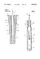
- FIG. 1illustrates schematically the prior art practice of telescoping liner sections.
- FIG. 2illustrates schematically a liner and liner assembly according to the invention.
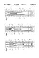
- FIGS. 3 and 4illustrate sectional views of liner expansion tools according to the invention.
- FIGS. 5 through 7illustrate schematically the pipe expansion method or process of the invention.
- FIG. 1there is shown a well string 1 extending to the earth surface 2 and to conductor pipe or casing 3.
- Conductor pipe 3is positioned in the portion 4a of wellbore 4, while pipe 5 is in reduced diameter section 4b of the same wellbore.
- the wellboreforms segmented annulus 6 with pipes 3 and 5, the width of the annulus segments being the same or approximately the same.
- a further reduced diameter section 9is illustrated.
- standard cementing operationsprovide a cemented annulus which stabilizes the wellbore, but the effective diameter of the conducting passage is progressively and substantially reduced as the well is deepened.
- FIG. 2illustrates an important aspect of the invention. Accordingly, in FIG. 2 there is shown a liner-die assembly designated generally as 10.
- the assemblyincludes the liner component 11 which, as shown, comprises a liner head section 12 which includes a section of reduced external and internal diameter coupled to a main body portion or remainder segment 13.
- the external diameter of the section of reduced external and internal diametermay be reduced from that of the remainder segment on the order of two inches or so, with a corresponding decrease in the internal diameter of the reduced diameter section.
- a “liner” or “casing”will be composed of segments or sections assembled and coupled by suitable means, such as by threading.
- the section of reduced external and internal diameter 12may be formed in one or composed of more than one section of liner, it being recognized that the remainder section or segment will normally comprise many sections (30 ft.) to the end or bottom end thereof.
- Head section 12which comprises a deformable material, preferably is connected to the main segment of the liner 13 by appropriate threading of the two segments. Alternately, not shown, the head section and a portion of the remainder or main body segment may be of integral construction.
- An elastic or compressible sleeve (e.g., rubber) or sleeves 12amay be provided on head section 12 for stability and sealing.
- a preferred fluid tight die assemblyindicated generally as 14, and described more fully hereinafter, is provided.
- the preferred assembly 14includes suitable mounting means or connecting means, such as a threaded connection 15, for connecting to a running string or other tool, and may be provided with threads or other suitable connecting means to connect to other tools, e.g., cementing operation components, indicated generally at 16, such as wiper plug launching apparatus, as described, for example, in U.S. Ser. No. 08/805,782, filed Feb. 25, 1997, by Gilbert Lavaure, Jason Jonas, and Bernard Piot, incorporated herein by reference.
- Liner segment 13is provided with suitable partial sealing means 17, such as a differential fill-up collar, at or near the end of the liner opposite the suspending or connecting means, to allow ingress of fluid into the liner during insertion thereof in the enlarged wellbore, seal the liner from ingress of fluid from the wellbore after its insertion, and prevent egress of fluid from the bore of segment 13 (as described more fully hereinafter).
- suitable partial sealing means 17such as a differential fill-up collar, at or near the end of the liner opposite the suspending or connecting means, to allow ingress of fluid into the liner during insertion thereof in the enlarged wellbore, seal the liner from ingress of fluid from the wellbore after its insertion, and prevent egress of fluid from the bore of segment 13 (as described more fully hereinafter).
- suitable partial sealing means 17such as a differential fill-up collar, at or near the end of the liner opposite the suspending or connecting means, to allow ingress of fluid into the liner during insertion thereof in the enlarged well
- FIG. 3illustrates the simplest form of the die member assembly. Accordingly, there is shown a die member 20 of suitable shape and composition, such as hardened steel, and adapted or sized and shaped to expand a liner section of reduced diameter. Other suitable die forming materials are well known, and the particular die member material utilized is a matter of choice.
- the die member 20comprises enlarged sections of variable diameter and is of generally frustoconical shape provided with suitable beveling in the segment of the die member where shaping of the liner section will be initiated, although other deforming shapes of the die member may be provided.
- the die memberwill be shaped or designed to provide an at least substantially uniform expanded or deformed liner segment of circular or approximately circular periphery, the die structure being selected to provide a periphery of the deformed and expanded segment equal to or approximating (slightly larger or less than) the periphery of the remainder segment of the liner.
- die structuresare known, for example, which will deform the reduced diameter segment to provide an expanded internal periphery slightly larger than that of the die. This aspect of the invention is preferred, since there is the possibility of a virtual force fit of the expanded section in the casing or upper liner.
- the die member 20further comprises a fluid tight seal 21, as previously described, such as a polymer cupseal, for sealing the die in a liner and allowing sufficient fluid pressure, as described hereinafter, to produce movement of the die member.
- a fluid tight seal 21such as a polymer cupseal
- the particular sealing materialmay be selected by those skilled in the art, a wide variety of sealing materials being suitable. For example, rubber or neoprene may also be utilized.
- the die memberis provided with a bore or means 22 for transmitting a fluid in its center, and the bore terminates at both ends thereof with or in connecting means.
- threadsare provided at 23 and 24 for connecting the die member to a running string or a tool, and suspending and/or positioning components, respectively.
- the die assembly showncomprises a pipe or generally tubular body 25 having threaded connecting means or segments 26 and 27 (box and pin) for connecting to a running string and suspending a tool or suitable cementing components in a liner, respectively.
- a die member 28is provided on pipe 25 and is preferably of integral construction therewith, being of suitable shape and composition, as described with respect to FIG. 3, and adapted or sized and shaped in a similar manner to expand a liner section such as liner section 12.
- the connecting meansin whatever form employed, e.g., as also shown in FIG. 3, thus enables the positioning or adjustment of the position of the die member in a liner by movement, for example, of a drillstring attached thereto.
- die member 28may be mounted on pipe 25 by suitable mounting means (not shown).
- the die member 28comprises enlarged sections of variable diameter and is of generally frustoconical shape provided with suitable beveling in the segment of the die member where shaping of the liner section 12 will be initiated, although other deforming shapes of the die member may be provided.
- the die member 28further comprises a fluid tight seal 29, as previously described.
- FIG. 5the liner assembly is provided in a wellbore 30, such as an oil or gas well bore, and positioned in relation to cemented casing 31, as shown.
- Wellbore 30has a diameter greater than the external diameter of casing 31, such wellbores being obtainable by use of a bi-center bit, under-reamer bit, or similar tool known to those skilled in the art.
- the external diameter of liner segment 13is preferably slightly smaller than the internal diameter of casing 31, being just sufficiently smaller to allow lowering thereof through casing 31.
- the liner assemblyis positioned in the enlarged wellbore, as shown, so that fluids, e.g., drilling mud or cement slurry, may be passed down the string 1 and via the pipe or bore 25 into the liner segment 13 or suitable tools or structure therein, described more fully hereinafter, out of the liner segment 13, and into the wellbore annulus 32, and through the annulus segment 33, which is formed by the external wall of section 12 and the lower portion of casing 31.
- Liner section 12is formed, as mentioned, of a deformable liner material, such as a metal, e.g., steel or other alloy, which is suitable for liner duty.
- the term "deformable"is understood in its common sense as indicating a capacity for shaping or expansion by suitable application of mechanical pressure.
- the fluid tight die assemblyis positioned or disposed in the liner so that the longitudinal axes of the pipe and the liner are coincident.
- Pipe 25may be of variable length and may or may not extend from liner 11.
- the inventionis particularly adapted to use of liners of decreased wall thickness.
- liner segment 13is provided with suitable structure 17, at or near the end of the remainder segment of the liner, disposed from the die assembly, to allow ingress of fluid from the wellbore, such as a displacement fluid, during insertion of the liner, and sealing of the liner from ingress of cement slurry after cementing.
- a differential fill-up collarwill be employed at or near the bottom of the liner to prevent wellbore fluids from entering the liner, and any suitable such collar or similar device may be employed.
- a variety of such devicesare described in Well Cementing, edited by E. I. Nelson, Schlumberger Educational Services (1990), and the selection of a particular device is well within the ambit of those skilled in the art.
- suitable sealing meansmay be provided to prevent egress of fluid from the liner.
- the wiper plug system described in the aforementioned Ser. No. 08/805,782may be employed, to the effect that a fluid tight seal is formed at the end of the liner distant from the assembly, or the bottom of the liner.
- the liner assemblyis especially adapted to a cementing operation, and hanger elements are not required since the liner assembly may be supported by the string 1. More particularly, following standard cementing procedures, cement slurry may be pumped downhole through the string 1 and through liner 11 via pipe 25 in the die assembly, through flow distributor 16, which may be that of the aforementioned wiper plug launching system, and out the bottom of the liner through open sealing means 17.
- the cement slurrydisplaces drilling fluid and/or a suitable spacer fluid between the cement slurry and the drilling fluid in the wellbore annulus, the drilling fluid and/or spacer fluid passing from annulus 32 into annulus 33 in casing 31 without substantial impediment.
- sealing means 17(schematically shown) at the bottom of liner section 13 is sealed to the ingress and egress of fluid.
- a wiper plugwhich is solid, is sent downhole, after sufficient cement slurry has been sent into annulus 32, to seal, with the differential fillup collar, the bottom of liner to egress of fluid.
- the technique of the aforementioned Ser. No. 08/805,782is preferred. Fluid pressure is then applied to the bore of the liner segment 13 by pumping a fluid through the pipe 25 into the bore of liner 13.
- Any suitable wellbore fluid or liquid availablemay be used, e.g., a displacement fluid, a completion fluid, water, or sea water.
- the fluidis pumped at sufficient pressure, e.g., 3000 psig, through pipe 25 to provide upward movement of die member 28 if the member is freed for movement.
- sufficient pressuree.g. 3000 psig
- the position of the die assembly(including die member 28) is adjusted or allowed to adjust upward by gradual upward movement of the running string 1.
- Adjustment of the drillstring lengthis made at a rate sufficient to move the die member upward or allow upward movement thereof, caused by the pressure on the die, at a controlled rate, in response to such continued sufficient application of fluid pressure, the continued application of sufficient pressure being indicated by change in drillstring weight.
Landscapes
- Life Sciences & Earth Sciences (AREA)
- Engineering & Computer Science (AREA)
- Geology (AREA)
- Mining & Mineral Resources (AREA)
- Physics & Mathematics (AREA)
- Environmental & Geological Engineering (AREA)
- Fluid Mechanics (AREA)
- General Life Sciences & Earth Sciences (AREA)
- Geochemistry & Mineralogy (AREA)
- Earth Drilling (AREA)
Abstract
Description
This invention relates to a method for cementing a well and to apparatus useful in well cementing operations.
In the conventional drilling of a well, such as an oil well, a series of casings and/or liners are commonly installed sequentially in the wellbore or borehole. In standard practice, each succeeding liner placed in the wellbore has an outside diameter significantly reduced in size when compared to the casing or liner previously installed. Commonly, after the installation of each casing or liner, cement slurry is pumped downhole and back up into the space or annulus between the casing or liner and the wall of the wellbore, in an amount sufficient to fill the space. The cement slurry, upon setting, stabilizes the casing or liner in the wellbore, prevents fluid exchange between or among formation layers through which the wellbore passes, and prevents gas from rising up the wellbore.
The use of a series of liners which have sequentially reduced diameters is derived from long experience and is aimed at avoiding problems at the time of insertion of casing or liner installation in the wellbore. The number of liners or casings required to reach a given target location is determined principally by the properties of the formations penetrated and by the pressures of the fluids contained in the formations. If the driller encounters an extended series of high pressure/low pressure configurations, the number of liners required under such circumstances may be such that the well cannot usefully be completed because of the continued reduction of the liner diameters required. Again, a further problem of the standard well liner configuration is that large volumes of cuttings are produced initially, and heavy logistics are required during early phases of drilling.
While several approaches to the resolution of these problems have been attempted, none have proven totally satisfactory. Accordingly, there has existed a need for a well lining and cementing technique or procedure, and means to carry it out, which would eliminate or significantly reduce the degree of diameter reduction required when a series of well liners must be inserted. The invention addresses this need.
There is thus provided, in one embodiment, a method or process, useful in cementing a well, especially a hydrocarbon well, which is characterized by the use of increased external and internal diameter liners, i.e., by a reduction in the degree of diameter reduction of the liners required, and which does not require excessively large initial conductor casing or surface pipe. Accordingly, in this embodiment, the invention relates to a method of cementing a wellbore in which a casing or first liner is provided in a wellbore. (As utilized herein, the terms "first" and "second", etc., in relation to the casing or liners mentioned, are relative, it being understood that, after the initial "second" casing or liner is cemented, it may become a "first" liner for the next cementing operation as such operations proceed down the wellbore.)
Further drilling operations are then conducted to provide an enlarged wellbore. As used herein, the term "enlarged wellbore" refers to a wellbore or borehole having a diameter greater than that of the internal diameter of the casing or preceding liner, preferably greater than the external diameter of the casing or preceding liner, such a wellbore being provided or drilled in a manner known to those skilled in the art, as described more fully hereinafter. At a desired depth, or when it is otherwise decided to line and cement the enlarged wellbore, a second liner, whose greatest external (outside) diameter approximates, i.e., is only slightly smaller than the internal diameter of the casing or first liner provided, is then provided in the enlarged wellbore through the casing or first liner. The second liner comprises a minor section or segment of significantly or further reduced external and internal diameter (in relation to the remaining or remainder segment of the second liner) and is composed, at least in said minor section, of a deformable liner material. According to the invention, the second liner is positioned in relation to the enlarged wellbore so that the section of reduced external diameter is located or positioned in the lower portion of the casing or first liner and the remainder segment below the lower portion, in such manner that fluid may circulate freely, i.e., without substantial or significant impediment, in the annuli formed by the second liner and the enlarged wellbore and the internal wall of the casing or first liner.
Inside the bore of the larger remaining or remainder segment of the second liner there is disposed or provided, as more fully described hereinafter, a movable, fluid tight die member of appropriate dimensions, preferably positioned in the second liner distant from the bottom of the remainder segment and proximate the minor section of reduced external and internal diameter, and which, after initial positioning or installation in the enlarged wellbore, is fixed in relation to said wellbore. As utilized herein, the phrase "fluid tight", in reference to the die member, is understood to indicate that the die member is appropriately sized and shaped and contains appropriate sealing means to prevent significant passage of fluid, even under substantial pressure, as described hereinafter, past its periphery or circumference which is contiguous to the interior wall or bore of the remainder segment of the second liner. The fluid tight die member, including the sealing means, is further a component or element of the novel die-expansion assembly of the invention which comprises means for transmitting a fluid to the bore of a liner, and means for connecting the die member to a drillstring. The latter means are important in positioning the novel liner-die assembly in the enlarged wellbore initially, as described more fully hereinafter, and in responding to applied fluid pressure. As utilized herein, the term "drillstring" is understood to include tool members or collars, etc., normally utilized in wellbore operations. In the specific context of the invention, the die-expansion assembly comprises means for transmitting a fluid to the bore of the remainder segment of the second liner, to the end that a fluid under significant pressure may be applied to the bore of the remainder segment of the second liner, and further comprises means for connecting the die member to a drillstring.
According to the method of the invention, upon proper positioning of the liner-die assembly of the invention in the wellbore, cement slurry is then pumped down the drillstring through the casing or first liner and the second liner (via the means for transmitting a fluid) and into the enlarged wellbore annulus in an amount sufficient to cement the wellbore annulus. After the cement is in place, the bottom or bottom end of the second liner is sealed, by standard techniques known to those skilled in the art, to prevent egress of fluid from the liner. As utilized herein, reference to the "bottom" or "bottom end" of the liner is to be construed as referring to a site downhole on or in the liner rather than as a precise location of the liner body. The sealing of the bottom end of the liner, coupled with the seal provided by the fluid tight die member, provides or constitutes, assuming a location of the die member removed or distant from the bottom of the liner, and, with the exception of communication with the aforementioned means for transmitting a fluid, a sealed compartment or recess in the bore of the remainder segment of the second liner. Substantial fluid pressure is then applied to the interior of this sealed remainder segment recess by pumping a fluid, e.g., a wellbore fluid such as a drilling fluid or a spacer fluid, through said means for transmitting a fluid which communicates with the compartment or recess. As fluid under pressure is introduced into the otherwise sealed recess, the increasing pressure therein tends to force the fluid tight die member up the second liner bore. According to the invention, as fluid pressure is increased in the sealed recess, the position of the die-expansion assembly, including the die member, is mechanically adjusted or allowed to adjust by translation upward in the liner (and the wellbore). The rate of upward adjustment or movement of the die-expansion assembly by upward movement of the running string and the application of pressure to the second liner bore recess are correlated so as to produce movement of the die member up through the section of reduced diameter with concurrent gradual deformation and expansion of the section of reduced diameter, providing an expanded section or segment having an external diameter equal to or approximating, preferably slightly greater or larger than that of the remainder segment of the second liner, as described more fully hereinafter. The expansion of the section provides an external diameter for the section which more closely approximates the internal diameter of the casing or first liner, while providing a larger flow passage internally for production fluids. Continued application of fluid pressure and correlated upward translation or adjustment of the position of the die-expansion assembly frees the die member from the second liner, the second liner then being positioned or allowed to remain with a substantial minor portion of the newly expanded segment in the casing or first liner. The cement slurry in the wellbore annulus is then allowed to set.
In yet further embodiments, the invention relates to a novel liner, which may additionally include expansion means therein; to an apparatus or tool for expansion of a liner having a reduced diameter section; and to a novel liner-die assembly or combination which is useful in cementing operations. More particularly, the liner of the invention comprises a wellbore liner having a minor section of reduced external and internal diameter composed of a deformable material and a larger remainder section of increased external and internal diameter. The expansion device or apparatus of the invention comprises unique fluid tight die means adapted for expansion of a liner section of reduced internal and external diameter, and preferably comprises a means for transmitting a fluid, e.g., a pipe; a die member adapted for expanding, at least substantially uniformly, the bore of a liner, on the periphery of said pipe; and sealing means positioned on the periphery of the die member adapted to provide a fluid tight seal between the bore of a liner and said die member. In the preferred arrangement, the pipe is provided at one end thereof with means for connecting the pipe to, or for suspending the pipe from, a drillstring, and is further preferably provided at the opposite end thereof with means for suspending a tool, preferably components used in cementing operations, and, especially, in one aspect of the invention, means to assist in sealing the end of the liner distant from said opposite end of the pipe.
The invention further relates to a novel liner-die assembly. In this aspect, the invention comprises the novel wellbore liner in which there is disposed the die-expansion assembly of the invention, as described, the assembly being disposed in said liner with the longitudinal axis of the means for transmitting fluid, or pipe, coincident with the axis of the liner and the fluid tight die member positioned in the remainder segment of the liner.
FIG. 1 illustrates schematically the prior art practice of telescoping liner sections.
FIG. 2 illustrates schematically a liner and liner assembly according to the invention.
FIGS. 3 and 4 illustrate sectional views of liner expansion tools according to the invention.
FIGS. 5 through 7 illustrate schematically the pipe expansion method or process of the invention.
For a fuller understanding of the invention, reference is made to the drawing. Accordingly, in FIG. 1 there is shown a well string 1 extending to theearth surface 2 and to conductor pipe orcasing 3.Conductor pipe 3 is positioned in theportion 4a ofwellbore 4, whilepipe 5 is in reduceddiameter section 4b of the same wellbore. The wellbore forms segmentedannulus 6 withpipes diameter section 9 is illustrated. As indicated, standard cementing operations provide a cemented annulus which stabilizes the wellbore, but the effective diameter of the conducting passage is progressively and substantially reduced as the well is deepened.
FIG. 2 illustrates an important aspect of the invention. Accordingly, in FIG. 2 there is shown a liner-die assembly designated generally as 10. The assembly includes theliner component 11 which, as shown, comprises aliner head section 12 which includes a section of reduced external and internal diameter coupled to a main body portion orremainder segment 13. In a practical case, the external diameter of the section of reduced external and internal diameter may be reduced from that of the remainder segment on the order of two inches or so, with a corresponding decrease in the internal diameter of the reduced diameter section. As will be understood by those skilled in the art, a "liner" or "casing" will be composed of segments or sections assembled and coupled by suitable means, such as by threading. In the present invention, the section of reduced external andinternal diameter 12 may be formed in one or composed of more than one section of liner, it being recognized that the remainder section or segment will normally comprise many sections (30 ft.) to the end or bottom end thereof.Head section 12, which comprises a deformable material, preferably is connected to the main segment of theliner 13 by appropriate threading of the two segments. Alternately, not shown, the head section and a portion of the remainder or main body segment may be of integral construction. An elastic or compressible sleeve (e.g., rubber) orsleeves 12a may be provided onhead section 12 for stability and sealing. A preferred fluid tight die assembly, indicated generally as 14, and described more fully hereinafter, is provided. Thepreferred assembly 14 includes suitable mounting means or connecting means, such as a threadedconnection 15, for connecting to a running string or other tool, and may be provided with threads or other suitable connecting means to connect to other tools, e.g., cementing operation components, indicated generally at 16, such as wiper plug launching apparatus, as described, for example, in U.S. Ser. No. 08/805,782, filed Feb. 25, 1997, by Gilbert Lavaure, Jason Jonas, and Bernard Piot, incorporated herein by reference.Liner segment 13 is provided with suitable partial sealing means 17, such as a differential fill-up collar, at or near the end of the liner opposite the suspending or connecting means, to allow ingress of fluid into the liner during insertion thereof in the enlarged wellbore, seal the liner from ingress of fluid from the wellbore after its insertion, and prevent egress of fluid from the bore of segment 13 (as described more fully hereinafter). As will be evident to those skilled in the art, a portion of the liner containing the die assembly may suitably be lowered into a wellbore as a unit, to the purpose that, upon completion of the cementing and deforming technique described more fully hereinafter, a suitable cemented liner combination of genuine advantage is provided.
FIG. 3 illustrates the simplest form of the die member assembly. Accordingly, there is shown adie member 20 of suitable shape and composition, such as hardened steel, and adapted or sized and shaped to expand a liner section of reduced diameter. Other suitable die forming materials are well known, and the particular die member material utilized is a matter of choice. In the illustration, thedie member 20 comprises enlarged sections of variable diameter and is of generally frustoconical shape provided with suitable beveling in the segment of the die member where shaping of the liner section will be initiated, although other deforming shapes of the die member may be provided. In each application of the invention, the die member will be shaped or designed to provide an at least substantially uniform expanded or deformed liner segment of circular or approximately circular periphery, the die structure being selected to provide a periphery of the deformed and expanded segment equal to or approximating (slightly larger or less than) the periphery of the remainder segment of the liner. As will be recognized by those skilled in the art, die structures are known, for example, which will deform the reduced diameter segment to provide an expanded internal periphery slightly larger than that of the die. This aspect of the invention is preferred, since there is the possibility of a virtual force fit of the expanded section in the casing or upper liner.
In this illustration, thedie member 20 further comprises a fluidtight seal 21, as previously described, such as a polymer cupseal, for sealing the die in a liner and allowing sufficient fluid pressure, as described hereinafter, to produce movement of the die member. The particular sealing material may be selected by those skilled in the art, a wide variety of sealing materials being suitable. For example, rubber or neoprene may also be utilized. The die member is provided with a bore or means 22 for transmitting a fluid in its center, and the bore terminates at both ends thereof with or in connecting means. Thus, threads are provided at 23 and 24 for connecting the die member to a running string or a tool, and suspending and/or positioning components, respectively.
A preferred embodiment of the die assembly is illustrated in greater detail in FIG. 4. The die assembly shown comprises a pipe or generallytubular body 25 having threaded connecting means orsegments 26 and 27 (box and pin) for connecting to a running string and suspending a tool or suitable cementing components in a liner, respectively. Adie member 28 is provided onpipe 25 and is preferably of integral construction therewith, being of suitable shape and composition, as described with respect to FIG. 3, and adapted or sized and shaped in a similar manner to expand a liner section such asliner section 12. The connecting means, in whatever form employed, e.g., as also shown in FIG. 3, thus enables the positioning or adjustment of the position of the die member in a liner by movement, for example, of a drillstring attached thereto. If not of integral construction, diemember 28 may be mounted onpipe 25 by suitable mounting means (not shown). In a manner similar to the embodiment of FIG. 3, thedie member 28 comprises enlarged sections of variable diameter and is of generally frustoconical shape provided with suitable beveling in the segment of the die member where shaping of theliner section 12 will be initiated, although other deforming shapes of the die member may be provided. Thedie member 28 further comprises a fluidtight seal 29, as previously described.
The procedure of the invention and operation of theliner 10 assembly and dieassembly 14 are understood more fully by reference to schematic FIGS. 5 through 7. Elements previously described with respect to FIGS. 1 through 4 are referred to by identical numbers. Accordingly, in FIG. 5 the liner assembly is provided in awellbore 30, such as an oil or gas well bore, and positioned in relation to cementedcasing 31, as shown.Wellbore 30 has a diameter greater than the external diameter ofcasing 31, such wellbores being obtainable by use of a bi-center bit, under-reamer bit, or similar tool known to those skilled in the art. The external diameter ofliner segment 13 is preferably slightly smaller than the internal diameter ofcasing 31, being just sufficiently smaller to allow lowering thereof throughcasing 31. The liner assembly is positioned in the enlarged wellbore, as shown, so that fluids, e.g., drilling mud or cement slurry, may be passed down the string 1 and via the pipe or bore 25 into theliner segment 13 or suitable tools or structure therein, described more fully hereinafter, out of theliner segment 13, and into thewellbore annulus 32, and through theannulus segment 33, which is formed by the external wall ofsection 12 and the lower portion ofcasing 31.Liner section 12 is formed, as mentioned, of a deformable liner material, such as a metal, e.g., steel or other alloy, which is suitable for liner duty. As used herein, the term "deformable" is understood in its common sense as indicating a capacity for shaping or expansion by suitable application of mechanical pressure. The fluid tight die assembly is positioned or disposed in the liner so that the longitudinal axes of the pipe and the liner are coincident.Pipe 25 may be of variable length and may or may not extend fromliner 11. As will be evident to those skilled in the art, the invention is particularly adapted to use of liners of decreased wall thickness.
As previously mentioned,liner segment 13 is provided withsuitable structure 17, at or near the end of the remainder segment of the liner, disposed from the die assembly, to allow ingress of fluid from the wellbore, such as a displacement fluid, during insertion of the liner, and sealing of the liner from ingress of cement slurry after cementing. In the usual case, a differential fill-up collar will be employed at or near the bottom of the liner to prevent wellbore fluids from entering the liner, and any suitable such collar or similar device may be employed. A variety of such devices are described in Well Cementing, edited by E. I. Nelson, Schlumberger Educational Services (1990), and the selection of a particular device is well within the ambit of those skilled in the art. Additionally, in order to seal the bottom of the liner after the cement has been placed in the wellbore annulus, as more fully described hereinafter, suitable sealing means, known to those skilled in the art, may be provided to prevent egress of fluid from the liner. Preferably, the wiper plug system described in the aforementioned Ser. No. 08/805,782 may be employed, to the effect that a fluid tight seal is formed at the end of the liner distant from the assembly, or the bottom of the liner.
In the position shown in FIG. 5, the liner assembly is especially adapted to a cementing operation, and hanger elements are not required since the liner assembly may be supported by the string 1. More particularly, following standard cementing procedures, cement slurry may be pumped downhole through the string 1 and throughliner 11 viapipe 25 in the die assembly, throughflow distributor 16, which may be that of the aforementioned wiper plug launching system, and out the bottom of the liner through open sealing means 17. The cement slurry displaces drilling fluid and/or a suitable spacer fluid between the cement slurry and the drilling fluid in the wellbore annulus, the drilling fluid and/or spacer fluid passing fromannulus 32 intoannulus 33 incasing 31 without substantial impediment. The advantage of the reduced cross section ofsegment 12, which permits flow of fluids out of the wellbore, is demonstrated at this juncture. Without such feature, the ultimate goal of a wider cross section for production fluids cannot be achieved because of the requirement for removal of fluids from the borehole annulus. Sufficient cement slurry is employed to fill theannulus 32. The invention now provides for expansion ofsection 12 to provide for a larger diameter cross section corresponding to that ofsection 13.
As shown in FIG. 6, sealing means 17 (schematically shown) at the bottom ofliner section 13 is sealed to the ingress and egress of fluid. In the normal case, a wiper plug, which is solid, is sent downhole, after sufficient cement slurry has been sent intoannulus 32, to seal, with the differential fillup collar, the bottom of liner to egress of fluid. As mentioned, the technique of the aforementioned Ser. No. 08/805,782 is preferred. Fluid pressure is then applied to the bore of theliner segment 13 by pumping a fluid through thepipe 25 into the bore ofliner 13. Any suitable wellbore fluid or liquid available may be used, e.g., a displacement fluid, a completion fluid, water, or sea water. The fluid is pumped at sufficient pressure, e.g., 3000 psig, throughpipe 25 to provide upward movement ofdie member 28 if the member is freed for movement. To this end, the position of the die assembly (including die member 28) is adjusted or allowed to adjust upward by gradual upward movement of the running string 1. Adjustment of the drillstring length is made at a rate sufficient to move the die member upward or allow upward movement thereof, caused by the pressure on the die, at a controlled rate, in response to such continued sufficient application of fluid pressure, the continued application of sufficient pressure being indicated by change in drillstring weight. As continuing sufficient fluid pressure moves diemember 28 upward, its movement causes thedie member 28 to expand and shape thedeformable liner section 12 so that the section diameter and radial cross section thereof equals or approximates the diameter and radial cross section of thelower section 13. Further application of fluid pressure in the bore ofliner 11 with continued adjustment of the position ofdie member 28 will free the die 28 from theliner 11, as shown in FIG. 7. The result of the deformation operation is the provision of anupper segment 12 of theliner 11 which now corresponds in size to that oflower segment 13. The cement is then allowed to set, producing a stabilized wellbore with increased flow capability over conventional liner sequence technique.
While the invention has been described with reference to specific embodiments, it is understood that various modifications and embodiments will be suggested to those skilled in the art upon reading and understanding this disclosure. Accordingly, it is intended that all such modifications and embodiments be included within the invention and that the scope of the invention be limited only by the appended claims.
Claims (12)
1. A method of cementing a wellbore comprising providing a casing in a wellbore and drilling a further segment of enlarged wellbore;
providing in the enlarged wellbore, through the casing, a liner of smaller external diameter comprising a minor section of further reduced external and internal diameter composed of a deformable liner material, and a remainder segment having an external diameter approximating the internal diameter of the casing, containing a movable fluid tight die member in the bore thereof at a location in the bore distant from the bottom end of said remainder segment, the liner further comprising means for transmitting a fluid to the bore of the remainder segment below the fluid tight die member, through the fluid tight die member, the section of reduced external and internal diameter being positioned in the lower portion of said casing in such manner, and the remainder segment of the liner below the lower portion of the casing in the enlarged wellbore, so that fluid may circulate without substantial impediment in the annuli formed by said liner and the enlarged wellbore and casing;
pumping a cement slurry down the casing and through the liner, and into the wellbore annulus in an amount sufficient to cement said wellbore annulus;
sealing the bottom of the remainder segment of the liner;
transmitting a fluid to and applying sufficient fluid pressure to the bore of the remainder segment of the liner below the fluid tight die member to move the die member up the liner and expand said minor section, and allowing said fluid tight die member to move up the wellbore to provide an external diameter of the minor section equal to or approximating that of the remainder segment of the liner;
and removing the fluid tight die member from the expanded minor section and allowing the cement to set.
2. A method of cementing a wellbore comprising
providing a first liner in a wellbore and drilling a further segment of enlarged wellbore;
providing in the enlarged wellbore, through the first liner, a second liner of smaller external diameter comprising a minor section of further reduced external and internal diameter composed of a deformable liner material, and a remainder segment having an external diameter approximating the internal diameter of the liner, containing a fluid tight die member in the bore thereof, at a location in the bore distant from the bottom end of said remainder segment, the liner further comprising means for transmitting a fluid to the bore of the remainder segment below the fluid tight die member, through the fluid tight die member, the section of reduced external and internal diameter being positioned in the lower portion of said first liner in such manner, and the remainder segment of the second liner below the lower portion of the first liner in the enlarged wellbore, so that fluid may circulate without substantial impediment in the annuli formed by said liner and the enlarged wellbore and first liner;
pumping a cement slurry down the first liner and through the second liner, and into the wellbore annulus in an amount sufficient to cement said wellbore annulus;
sealing the bottom of the remainder segment of the second liner;
transmitting a fluid to and applying sufficient fluid pressure to the bore of the remainder segment of the second liner below the fluid tight die member to move the die member up the liner and expand said minor section, and allowing said fluid tight die to move up the wellbore to provide an external diameter of the minor section equal to or approximating that of the remainder segment of the liner;
and removing the fluid tight die member from the expanded minor section and allowing the cement to set.
3. An improved wellbore liner for ameliorating subsequent casing diameter reduction, comprising a section of reduced external and internal diameter composed of a deformable liner material and a larger remainder segment of increased external and internal diameter, and a fluid tight die member disposed in the bore of the remainder segment, wherein the fluid tight die member comprises a means for transmitting a fluid therethrough, and comprising a means for sealing an end of said liner at a location removed from the fluid tight die member.
4. Apparatus comprising a die member adapted for expanding, at least substantially uniformly, the bore of a liner;
sealing means positioned on the periphery of said die member adapted to provide a fluid tight seal between the bore of a liner and said die member;
means for transmitting a fluid through the die member;
means for connecting the die member to a drillstring;
and means for suspending a tool from the die member.
5. Apparatus comprising a pipe, a die member adapted for expanding, at least substantially uniformly, the bore of a liner, on the periphery of said pipe, and sealing means positioned on the periphery of said die member adapted to provide a fluid tight seal between the bore of said liner and said die member.
6. The apparatus of claim 5 wherein the pipe is provided at one end thereof with means for connecting the pipe to a drillstring.
7. Apparatus comprising a pipe, a die member adapted for expanding, at least substantially uniformly, the bore of a liner, on the periphery of said pipe, and sealing means positioned on the periphery of said die member adapted to provide a fluid tight seal between the bore of said liner and said die member, and wherein said pipe is provided at one end thereof with a means for connecting the pipe and at the opposite end thereof, a means for suspending a tool.
8. A wellbore liner for ameliorating subsequent casing diameter reduction associated with subterranean drilling operations comprising
(a) a section of reduced external and internal diameter composed of a deformable liner material and a larger remainder segment of increased external and internal diameter;
(b) a fluid tight die assembly disposed in said liner, said assembly comprising a fluid tight die member including a sealing means on the periphery of a pipe, the assembly disposed in said liner with the longitudinal axis of the pipe coincident with the axis of the liner and the fluid tight die member positioned in the remainder segment of the liner.
9. A wellbore liner comprising a section of reduced external and internal diameter composed of a deformable liner material and a larger remainder segment of increased external and internal diameter, and at least one sleeve composed of a compressible material mounted on the periphery of the section of reduced external and internal diameter.
10. The liner of claim 9 in which the compressible material is rubber.
11. A method of cementing a wellbore comprising providing a casing in a wellbore and drilling a further segment of enlarged wellbore;
providing in the enlarged wellbore, through the casing, and connected to a drillstring, a liner of smaller external diameter comprising a minor section of further reduced external and internal diameter composed of a deformable liner material, and a remainder segment having an external diameter approximating the internal diameter of the casing, containing a movable fluid tight die member in the bore thereof at a location in the bore distant from the bottom end of said remainder segment, the liner further comprising means for transmitting a fluid to the bore of the remainder segment below the fluid tight die member, through the fluid tight die member, the section of reduced external and internal diameter being positioned in the lower portion of said casing in such manner, and the remainder segment of the liner below the lower portion of the casing in the enlarged wellbore, so that fluid may circulate without substantial impediment in the annuli formed by said liner and the enlarged wellbore and casing;
pumping a cement slurry down the casing and through the liner, and into the wellbore annulus in an amount sufficient to cement said wellbore annulus;
sealing the bottom of the remainder segment of the liner;
transmitting a fluid to and applying sufficient fluid pressure to the bore of the remainder segment of the liner below the fluid tight die member to move the die member up the liner and expand said minor section, and moving said fluid tight die member up the wellbore in response to continued sufficient fluid pressure by adjusting the position of the drillstring upward, to provide an external diameter of the minor section equal to or approximating that of the remainder segment of the liner;
and removing the fluid tight die member from the expanded minor section and allowing the cement to set.
12. The method of claim 11 wherein the well is a hydrocarbon well.
Priority Applications (7)
| Application Number | Priority Date | Filing Date | Title |
|---|---|---|---|
| US08/863,652US6085838A (en) | 1997-05-27 | 1997-05-27 | Method and apparatus for cementing a well |
| CA002234386ACA2234386C (en) | 1997-05-27 | 1998-04-08 | Method and apparatus for cementing a well |
| DK98400997TDK0881354T3 (en) | 1997-05-27 | 1998-04-24 | Method and apparatus for cementing a well |
| EP98400997AEP0881354B1 (en) | 1997-05-27 | 1998-04-24 | Method and apparatus for cementing a well |
| DE69820153TDE69820153T2 (en) | 1997-05-27 | 1998-04-24 | Method and device for cementing a borehole |
| NO19982371ANO316930B1 (en) | 1997-05-27 | 1998-05-26 | Method and apparatus for cementing an expandable casing |
| US10/184,996USRE38578E1 (en) | 1997-05-27 | 2002-06-28 | Method and apparatus for cementing a well |
Applications Claiming Priority (1)
| Application Number | Priority Date | Filing Date | Title |
|---|---|---|---|
| US08/863,652US6085838A (en) | 1997-05-27 | 1997-05-27 | Method and apparatus for cementing a well |
Related Child Applications (1)
| Application Number | Title | Priority Date | Filing Date |
|---|---|---|---|
| US10/184,996ReissueUSRE38578E1 (en) | 1997-05-27 | 2002-06-28 | Method and apparatus for cementing a well |
Publications (1)
| Publication Number | Publication Date |
|---|---|
| US6085838Atrue US6085838A (en) | 2000-07-11 |
Family
ID=25341501
Family Applications (2)
| Application Number | Title | Priority Date | Filing Date |
|---|---|---|---|
| US08/863,652CeasedUS6085838A (en) | 1997-05-27 | 1997-05-27 | Method and apparatus for cementing a well |
| US10/184,996Expired - LifetimeUSRE38578E1 (en) | 1997-05-27 | 2002-06-28 | Method and apparatus for cementing a well |
Family Applications After (1)
| Application Number | Title | Priority Date | Filing Date |
|---|---|---|---|
| US10/184,996Expired - LifetimeUSRE38578E1 (en) | 1997-05-27 | 2002-06-28 | Method and apparatus for cementing a well |
Country Status (6)
| Country | Link |
|---|---|
| US (2) | US6085838A (en) |
| EP (1) | EP0881354B1 (en) |
| CA (1) | CA2234386C (en) |
| DE (1) | DE69820153T2 (en) |
| DK (1) | DK0881354T3 (en) |
| NO (1) | NO316930B1 (en) |
Cited By (120)
| Publication number | Priority date | Publication date | Assignee | Title |
|---|---|---|---|---|
| US6328113B1 (en) | 1998-11-16 | 2001-12-11 | Shell Oil Company | Isolation of subterranean zones |
| WO2001098623A1 (en)* | 1998-11-16 | 2001-12-27 | Shell Oil Company | Radial expansion of tubular members |
| WO2002010550A1 (en)* | 2000-07-28 | 2002-02-07 | Enventure Global Technology | Liner hanger with standoffs |
| WO2002029199A1 (en)* | 2000-10-02 | 2002-04-11 | Shell Oil Company | Method and apparatus for casing expansion |
| WO2002066783A1 (en)* | 2001-02-20 | 2002-08-29 | Enventure Global Technology | Mono-diameter wellbore casing |
| WO2002068792A1 (en)* | 2001-01-17 | 2002-09-06 | Enventure Global Technology | Mono-diameter wellbore casing |
| US6446724B2 (en) | 1999-05-20 | 2002-09-10 | Baker Hughes Incorporated | Hanging liners by pipe expansion |
| US6454013B1 (en)* | 1997-11-01 | 2002-09-24 | Weatherford/Lamb, Inc. | Expandable downhole tubing |
| US6470966B2 (en) | 1998-12-07 | 2002-10-29 | Robert Lance Cook | Apparatus for forming wellbore casing |
| WO2002053867A3 (en)* | 2001-01-03 | 2003-02-06 | Enventure Global Technology | Mono-diameter wellbore casing |
| WO2003029607A1 (en)* | 2001-10-03 | 2003-04-10 | Enventure Global Technlogy | Mono-diameter wellbore casing |
| US6557640B1 (en)* | 1998-12-07 | 2003-05-06 | Shell Oil Company | Lubrication and self-cleaning system for expansion mandrel |
| US6568471B1 (en) | 1999-02-26 | 2003-05-27 | Shell Oil Company | Liner hanger |
| US6575250B1 (en) | 1999-11-15 | 2003-06-10 | Shell Oil Company | Expanding a tubular element in a wellbore |
| US6575240B1 (en)* | 1998-12-07 | 2003-06-10 | Shell Oil Company | System and method for driving pipe |
| US20030127225A1 (en)* | 2001-12-22 | 2003-07-10 | Harrall Simon John | Bore liner |
| US6604763B1 (en) | 1998-12-07 | 2003-08-12 | Shell Oil Company | Expandable connector |
| US6622797B2 (en) | 2001-10-24 | 2003-09-23 | Hydril Company | Apparatus and method to expand casing |
| US6634431B2 (en) | 1998-11-16 | 2003-10-21 | Robert Lance Cook | Isolation of subterranean zones |
| US6640903B1 (en) | 1998-12-07 | 2003-11-04 | Shell Oil Company | Forming a wellbore casing while simultaneously drilling a wellbore |
| WO2004003337A1 (en)* | 2002-06-26 | 2004-01-08 | Enventure Global Technology | System for radially expanding a tubular member |
| US20040031610A1 (en)* | 2002-08-13 | 2004-02-19 | Schultz Roger L. | Expanding well tools |
| US6712154B2 (en) | 1998-11-16 | 2004-03-30 | Enventure Global Technology | Isolation of subterranean zones |
| WO2003023179A3 (en)* | 2001-09-06 | 2004-04-08 | Enventure Global Technology | System for lining a wellbore casing |
| US6725919B2 (en) | 1998-12-07 | 2004-04-27 | Shell Oil Company | Forming a wellbore casing while simultaneously drilling a wellbore |
| US6732806B2 (en) | 2002-01-29 | 2004-05-11 | Weatherford/Lamb, Inc. | One trip expansion method and apparatus for use in a wellbore |
| US6742591B2 (en)* | 2000-09-20 | 2004-06-01 | Weatherford/Lamb, Inc. | Downhole apparatus |
| US6745845B2 (en) | 1998-11-16 | 2004-06-08 | Shell Oil Company | Isolation of subterranean zones |
| US6745846B1 (en) | 1999-09-06 | 2004-06-08 | E2 Tech Limited | Expandable downhole tubing |
| US6745853B2 (en) | 2002-10-04 | 2004-06-08 | Halliburton Energy Services, Inc. | Methods and apparatus for open hole drilling |
| WO2003016669A3 (en)* | 2001-08-20 | 2004-06-10 | Eventure Global Technology | Apparatus for radially expanding tubular members including a segmented expansion cone |
| US20040134668A1 (en)* | 2002-12-27 | 2004-07-15 | Mackay Alexander Craig | Downhole cutting tool and method |
| WO2003071086A3 (en)* | 2002-02-15 | 2004-07-22 | Enventure Global Technology | Mono-diameter wellbore casing |
| US20040149431A1 (en)* | 2001-11-14 | 2004-08-05 | Halliburton Energy Services, Inc. | Method and apparatus for a monodiameter wellbore, monodiameter casing and monobore |
| WO2004027205A3 (en)* | 2002-09-20 | 2004-08-05 | Enventure Global Technlogy | Mono diameter wellbore casing |
| GB2399120A (en)* | 2000-09-18 | 2004-09-08 | Shell Int Research | Forming a wellbore casing |
| US6789622B1 (en)* | 1999-09-06 | 2004-09-14 | Ez Tech Limited | Apparatus for and a method of anchoring an expandable conduit |
| GB2400624A (en)* | 2000-07-28 | 2004-10-20 | Enventure Global Technology | Coupling an expandable liner to a wellbore casing |
| US6823937B1 (en) | 1998-12-07 | 2004-11-30 | Shell Oil Company | Wellhead |
| US20050023001A1 (en)* | 2003-07-09 | 2005-02-03 | Hillis David John | Expanding tubing |
| US6860329B1 (en) | 1999-09-06 | 2005-03-01 | E2 Tech Limited | Apparatus for and method of including a packer to facilitate anchoring a first conduit to a second conduit |
| WO2004023014A3 (en)* | 2002-09-20 | 2005-03-03 | Enventure Global Technlogy | Threaded connection for expandable tubulars |
| WO2004076798A3 (en)* | 2003-02-26 | 2005-03-24 | Enventure Global Technology | Apparatus for radially expanding and plastically deforming a tubular member |
| US6892819B2 (en) | 1998-12-07 | 2005-05-17 | Shell Oil Company | Forming a wellbore casing while simultaneously drilling a wellbore |
| AU783245B2 (en)* | 1999-11-01 | 2005-10-06 | Shell Internationale Research Maatschappij B.V. | Wellbore casing repair |
| US6968618B2 (en) | 1999-04-26 | 2005-11-29 | Shell Oil Company | Expandable connector |
| US6976541B2 (en) | 2000-09-18 | 2005-12-20 | Shell Oil Company | Liner hanger with sliding sleeve valve |
| US7011161B2 (en) | 1998-12-07 | 2006-03-14 | Shell Oil Company | Structural support |
| US20060076147A1 (en)* | 2004-10-12 | 2006-04-13 | Lev Ring | Methods and apparatus for manufacturing of expandable tubular |
| US7055608B2 (en) | 1999-03-11 | 2006-06-06 | Shell Oil Company | Forming a wellbore casing while simultaneously drilling a wellbore |
| US7093653B2 (en) | 2002-10-25 | 2006-08-22 | Weatherford/Lamb | Downhole filter |
| US20060185855A1 (en)* | 2002-12-13 | 2006-08-24 | Jordan John C | Retractable joint and cementing shoe for use in completing a wellbore |
| US7100684B2 (en) | 2000-07-28 | 2006-09-05 | Enventure Global Technology | Liner hanger with standoffs |
| US7100685B2 (en) | 2000-10-02 | 2006-09-05 | Enventure Global Technology | Mono-diameter wellbore casing |
| US7104322B2 (en) | 2003-05-20 | 2006-09-12 | Weatherford/Lamb, Inc. | Open hole anchor and associated method |
| US7121352B2 (en) | 1998-11-16 | 2006-10-17 | Enventure Global Technology | Isolation of subterranean zones |
| US7168496B2 (en) | 2001-07-06 | 2007-01-30 | Eventure Global Technology | Liner hanger |
| US20070029082A1 (en)* | 2005-08-05 | 2007-02-08 | Giroux Richard L | Apparatus and methods for creation of down hole annular barrier |
| US7188687B2 (en) | 1998-12-22 | 2007-03-13 | Weatherford/Lamb, Inc. | Downhole filter |
| US20070062694A1 (en)* | 2005-07-22 | 2007-03-22 | Lev Ring | Apparatus and methods for creation of down hole annular barrier |
| US7195064B2 (en) | 1998-12-07 | 2007-03-27 | Enventure Global Technology | Mono-diameter wellbore casing |
| US7228901B2 (en) | 1994-10-14 | 2007-06-12 | Weatherford/Lamb, Inc. | Method and apparatus for cementing drill strings in place for one pass drilling and completion of oil and gas wells |
| US7231985B2 (en) | 1998-11-16 | 2007-06-19 | Shell Oil Company | Radial expansion of tubular members |
| US7234531B2 (en) | 1999-12-03 | 2007-06-26 | Enventure Global Technology, Llc | Mono-diameter wellbore casing |
| US7234542B2 (en) | 1994-10-14 | 2007-06-26 | Weatherford/Lamb, Inc. | Methods and apparatus for cementing drill strings in place for one pass drilling and completion of oil and gas wells |
| US20070187113A1 (en)* | 2006-02-15 | 2007-08-16 | Weatherford/Lamb, Inc. | Method and apparatus for expanding tubulars in a wellbore |
| US7258168B2 (en) | 2001-07-27 | 2007-08-21 | Enventure Global Technology L.L.C. | Liner hanger with slip joint sealing members and method of use |
| US7264067B2 (en) | 2003-10-03 | 2007-09-04 | Weatherford/Lamb, Inc. | Method of drilling and completing multiple wellbores inside a single caisson |
| US20070221374A1 (en)* | 2006-03-27 | 2007-09-27 | Grinaldi Ltd | High Performance Expandable Tubular System |
| US20070240878A1 (en)* | 2006-04-12 | 2007-10-18 | Grinaldi Ltd. | Apparatus for Radial Expansion of a Tubular |
| US7290616B2 (en) | 2001-07-06 | 2007-11-06 | Enventure Global Technology, L.L.C. | Liner hanger |
| US7290605B2 (en) | 2001-12-27 | 2007-11-06 | Enventure Global Technology | Seal receptacle using expandable liner hanger |
| US20070257486A1 (en)* | 2006-05-03 | 2007-11-08 | Grinaldi Ltd. | Elastomeric Seal for Expandable Connector |
| US7303022B2 (en) | 2002-10-11 | 2007-12-04 | Weatherford/Lamb, Inc. | Wired casing |
| US7308755B2 (en) | 2003-06-13 | 2007-12-18 | Shell Oil Company | Apparatus for forming a mono-diameter wellbore casing |
| US7311148B2 (en) | 1999-02-25 | 2007-12-25 | Weatherford/Lamb, Inc. | Methods and apparatus for wellbore construction and completion |
| US7334650B2 (en) | 2000-04-13 | 2008-02-26 | Weatherford/Lamb, Inc. | Apparatus and methods for drilling a wellbore using casing |
| US7350564B2 (en) | 1998-12-07 | 2008-04-01 | Enventure Global Technology, L.L.C. | Mono-diameter wellbore casing |
| US7350563B2 (en) | 1999-07-09 | 2008-04-01 | Enventure Global Technology, L.L.C. | System for lining a wellbore casing |
| US7360594B2 (en) | 2003-03-05 | 2008-04-22 | Weatherford/Lamb, Inc. | Drilling with casing latch |
| US7360591B2 (en) | 2002-05-29 | 2008-04-22 | Enventure Global Technology, Llc | System for radially expanding a tubular member |
| US7363984B2 (en) | 1998-12-07 | 2008-04-29 | Enventure Global Technology, Llc | System for radially expanding a tubular member |
| US7377326B2 (en) | 2002-08-23 | 2008-05-27 | Enventure Global Technology, L.L.C. | Magnetic impulse applied sleeve method of forming a wellbore casing |
| US7383889B2 (en) | 2001-11-12 | 2008-06-10 | Enventure Global Technology, Llc | Mono diameter wellbore casing |
| US7398832B2 (en) | 2002-06-10 | 2008-07-15 | Enventure Global Technology, Llc | Mono-diameter wellbore casing |
| US7404444B2 (en) | 2002-09-20 | 2008-07-29 | Enventure Global Technology | Protective sleeve for expandable tubulars |
| RU2330930C2 (en)* | 2003-05-05 | 2008-08-10 | Шелл Интернэшнл Рисерч Маатсхаппий Б.В. | Expansion device for expanding pipes |
| US7410000B2 (en) | 2001-01-17 | 2008-08-12 | Enventure Global Technology, Llc. | Mono-diameter wellbore casing |
| US7413020B2 (en) | 2003-03-05 | 2008-08-19 | Weatherford/Lamb, Inc. | Full bore lined wellbores |
| US7416027B2 (en) | 2001-09-07 | 2008-08-26 | Enventure Global Technology, Llc | Adjustable expansion cone assembly |
| US7424918B2 (en) | 2002-08-23 | 2008-09-16 | Enventure Global Technology, L.L.C. | Interposed joint sealing layer method of forming a wellbore casing |
| US7503393B2 (en) | 2003-01-27 | 2009-03-17 | Enventure Global Technology, Inc. | Lubrication system for radially expanding tubular members |
| US20090071661A1 (en)* | 2007-09-18 | 2009-03-19 | Lev Ring | Apparatus and methods for running liners in extended reach wells |
| US7513313B2 (en) | 2002-09-20 | 2009-04-07 | Enventure Global Technology, Llc | Bottom plug for forming a mono diameter wellbore casing |
| US7552776B2 (en) | 1998-12-07 | 2009-06-30 | Enventure Global Technology, Llc | Anchor hangers |
| US7571774B2 (en) | 2002-09-20 | 2009-08-11 | Eventure Global Technology | Self-lubricating expansion mandrel for expandable tubular |
| US20090229835A1 (en)* | 2005-11-07 | 2009-09-17 | Mohawk Energy Ltd. | Method and Apparatus for Downhole Tubular Expansion |
| US7603758B2 (en) | 1998-12-07 | 2009-10-20 | Shell Oil Company | Method of coupling a tubular member |
| US20100052319A1 (en)* | 2008-08-28 | 2010-03-04 | Mohawk Energy Ltd. | Dual Seal Expandable Tubular Connection |
| US7712522B2 (en) | 2003-09-05 | 2010-05-11 | Enventure Global Technology, Llc | Expansion cone and system |
| US7739917B2 (en) | 2002-09-20 | 2010-06-22 | Enventure Global Technology, Llc | Pipe formability evaluation for expandable tubulars |
| US7740076B2 (en) | 2002-04-12 | 2010-06-22 | Enventure Global Technology, L.L.C. | Protective sleeve for threaded connections for expandable liner hanger |
| US7775290B2 (en) | 2003-04-17 | 2010-08-17 | Enventure Global Technology, Llc | Apparatus for radially expanding and plastically deforming a tubular member |
| US7793721B2 (en) | 2003-03-11 | 2010-09-14 | Eventure Global Technology, Llc | Apparatus for radially expanding and plastically deforming a tubular member |
| US20100243277A1 (en)* | 2007-09-18 | 2010-09-30 | Lev Ring | Apparatus and methods for running liners in extended reach wells |
| US7819185B2 (en) | 2004-08-13 | 2010-10-26 | Enventure Global Technology, Llc | Expandable tubular |
| US7857052B2 (en) | 2006-05-12 | 2010-12-28 | Weatherford/Lamb, Inc. | Stage cementing methods used in casing while drilling |
| RU2410514C1 (en)* | 2010-04-05 | 2011-01-27 | Открытое акционерное общество "Татнефть" им. В.Д. Шашина | Method for well construction |
| US7886831B2 (en) | 2003-01-22 | 2011-02-15 | Enventure Global Technology, L.L.C. | Apparatus for radially expanding and plastically deforming a tubular member |
| US7918284B2 (en) | 2002-04-15 | 2011-04-05 | Enventure Global Technology, L.L.C. | Protective sleeve for threaded connections for expandable liner hanger |
| US7938201B2 (en) | 2002-12-13 | 2011-05-10 | Weatherford/Lamb, Inc. | Deep water drilling with casing |
| US20110220369A1 (en)* | 2010-03-15 | 2011-09-15 | Delange Richard W | Methods and apparatus relating to expansion tools for tubular strings |
| USRE42877E1 (en) | 2003-02-07 | 2011-11-01 | Weatherford/Lamb, Inc. | Methods and apparatus for wellbore construction and completion |
| US8276689B2 (en) | 2006-05-22 | 2012-10-02 | Weatherford/Lamb, Inc. | Methods and apparatus for drilling with casing |
| US20140041880A1 (en)* | 2012-08-07 | 2014-02-13 | Enventure Global Technology, Llc | Hybrid expansion cone |
| US8746028B2 (en) | 2002-07-11 | 2014-06-10 | Weatherford/Lamb, Inc. | Tubing expansion |
| US10107067B2 (en)* | 2015-09-22 | 2018-10-23 | Aarbakke Innovation, A.S. | Methods for placing a barrier material in a wellbore to permanently leave tubing in casing for permanent wellbore abandonment |
| US10837264B2 (en) | 2017-08-10 | 2020-11-17 | Mohawk Energy Ltd. | Casing patch system |
| US11530586B2 (en) | 2017-08-10 | 2022-12-20 | Coretrax Americas Limited | Casing patch system |
| US11788388B2 (en) | 2017-08-10 | 2023-10-17 | Coretrax Americas Limited | Casing patch system |
Families Citing this family (49)
| Publication number | Priority date | Publication date | Assignee | Title |
|---|---|---|---|---|
| US7036610B1 (en) | 1994-10-14 | 2006-05-02 | Weatherford / Lamb, Inc. | Apparatus and method for completing oil and gas wells |
| US7100710B2 (en) | 1994-10-14 | 2006-09-05 | Weatherford/Lamb, Inc. | Methods and apparatus for cementing drill strings in place for one pass drilling and completion of oil and gas wells |
| US6868906B1 (en) | 1994-10-14 | 2005-03-22 | Weatherford/Lamb, Inc. | Closed-loop conveyance systems for well servicing |
| US7147068B2 (en) | 1994-10-14 | 2006-12-12 | Weatherford / Lamb, Inc. | Methods and apparatus for cementing drill strings in place for one pass drilling and completion of oil and gas wells |
| US7013997B2 (en) | 1994-10-14 | 2006-03-21 | Weatherford/Lamb, Inc. | Methods and apparatus for cementing drill strings in place for one pass drilling and completion of oil and gas wells |
| US7108084B2 (en) | 1994-10-14 | 2006-09-19 | Weatherford/Lamb, Inc. | Methods and apparatus for cementing drill strings in place for one pass drilling and completion of oil and gas wells |
| US7509722B2 (en) | 1997-09-02 | 2009-03-31 | Weatherford/Lamb, Inc. | Positioning and spinning device |
| US6742596B2 (en) | 2001-05-17 | 2004-06-01 | Weatherford/Lamb, Inc. | Apparatus and methods for tubular makeup interlock |
| US6536520B1 (en) | 2000-04-17 | 2003-03-25 | Weatherford/Lamb, Inc. | Top drive casing system |
| GB9815809D0 (en) | 1998-07-22 | 1998-09-16 | Appleton Robert P | Casing running tool |
| GB2340858A (en) | 1998-08-24 | 2000-03-01 | Weatherford Lamb | Methods and apparatus for facilitating the connection of tubulars using a top drive |
| GB2340859A (en) | 1998-08-24 | 2000-03-01 | Weatherford Lamb | Method and apparatus for facilitating the connection of tubulars using a top drive |
| GB2340857A (en) | 1998-08-24 | 2000-03-01 | Weatherford Lamb | An apparatus for facilitating the connection of tubulars and alignment with a top drive |
| GB2345308B (en)* | 1998-12-22 | 2003-08-06 | Petroline Wellsystems Ltd | Tubing anchor |
| AU772327B2 (en) | 1998-12-22 | 2004-04-22 | Weatherford Technology Holdings, Llc | Procedures and equipment for profiling and jointing of pipes |
| GB2347441B (en) | 1998-12-24 | 2003-03-05 | Weatherford Lamb | Apparatus and method for facilitating the connection of tubulars using a top drive |
| GB2345074A (en) | 1998-12-24 | 2000-06-28 | Weatherford Lamb | Floating joint to facilitate the connection of tubulars using a top drive |
| US6857487B2 (en) | 2002-12-30 | 2005-02-22 | Weatherford/Lamb, Inc. | Drilling with concentric strings of casing |
| US6896075B2 (en) | 2002-10-11 | 2005-05-24 | Weatherford/Lamb, Inc. | Apparatus and methods for drilling with casing |
| GB2385356B (en)* | 1999-02-26 | 2003-10-08 | Shell Int Research | A method of applying a force to a piston |
| GB2348223B (en)* | 1999-03-11 | 2003-09-24 | Shell Internat Res Maatschhapp | Method of creating a casing in a borehole |
| EP1234090B1 (en)* | 1999-11-29 | 2003-08-06 | Shell Internationale Researchmaatschappij B.V. | Pipe connecting method |
| US7216727B2 (en) | 1999-12-22 | 2007-05-15 | Weatherford/Lamb, Inc. | Drilling bit for drilling while running casing |
| US7325610B2 (en) | 2000-04-17 | 2008-02-05 | Weatherford/Lamb, Inc. | Methods and apparatus for handling and drilling with tubulars or casing |
| GB0010378D0 (en) | 2000-04-28 | 2000-06-14 | Bbl Downhole Tools Ltd | Expandable apparatus for drift and reaming a borehole |
| GB2365463B (en) | 2000-08-01 | 2005-02-16 | Renovus Ltd | Drilling method |
| MY134794A (en)* | 2001-03-13 | 2007-12-31 | Shell Int Research | Expander for expanding a tubular element |
| GB0108638D0 (en)* | 2001-04-06 | 2001-05-30 | Weatherford Lamb | Tubing expansion |
| GB0111779D0 (en)* | 2001-05-15 | 2001-07-04 | Weatherford Lamb | Expanding tubing |
| US7172027B2 (en) | 2001-05-15 | 2007-02-06 | Weatherford/Lamb, Inc. | Expanding tubing |
| US7546881B2 (en) | 2001-09-07 | 2009-06-16 | Enventure Global Technology, Llc | Apparatus for radially expanding and plastically deforming a tubular member |
| GB0206227D0 (en) | 2002-03-16 | 2002-05-01 | Weatherford Lamb | Bore-lining and drilling |
| US6994176B2 (en) | 2002-07-29 | 2006-02-07 | Weatherford/Lamb, Inc. | Adjustable rotating guides for spider or elevator |
| US6899186B2 (en) | 2002-12-13 | 2005-05-31 | Weatherford/Lamb, Inc. | Apparatus and method of drilling with casing |
| US7128154B2 (en) | 2003-01-30 | 2006-10-31 | Weatherford/Lamb, Inc. | Single-direction cementing plug |
| CA2516649C (en) | 2003-02-27 | 2010-01-19 | Weatherford/Lamb, Inc. | Drill shoe |
| WO2004079147A2 (en) | 2003-03-05 | 2004-09-16 | Weatherford/Lamb, Inc. | Method and apparatus for drilling with casing |
| GB2415722B (en) | 2003-03-05 | 2007-12-05 | Weatherford Lamb | Casing running and drilling system |
| GB2436484B (en)* | 2003-03-05 | 2007-11-07 | Weatherford Lamb | Full bore lined wellbores |
| US7503397B2 (en) | 2004-07-30 | 2009-03-17 | Weatherford/Lamb, Inc. | Apparatus and methods of setting and retrieving casing with drilling latch and bottom hole assembly |
| WO2004090279A1 (en) | 2003-04-04 | 2004-10-21 | Weatherford/Lamb, Inc. | Method and apparatus for handling wellbore tubulars |
| US7650944B1 (en) | 2003-07-11 | 2010-01-26 | Weatherford/Lamb, Inc. | Vessel for well intervention |
| US7284617B2 (en) | 2004-05-20 | 2007-10-23 | Weatherford/Lamb, Inc. | Casing running head |
| US7540325B2 (en)* | 2005-03-14 | 2009-06-02 | Presssol Ltd. | Well cementing apparatus and method |
| US7322413B2 (en)* | 2005-07-15 | 2008-01-29 | Halliburton Energy Services, Inc. | Equalizer valve assembly |
| NO324088B1 (en)* | 2005-12-30 | 2007-08-13 | Statoil Asa | Method and extension pipe for cementing a drill well |
| US20100230100A1 (en)* | 2009-03-13 | 2010-09-16 | Reservoir Management Inc. | Plug for a Perforated Liner and Method of Using Same |
| US10570710B2 (en) | 2015-07-01 | 2020-02-25 | Shell Oil Company | Method and system for sealing a segmented expandable cone |
| MX2018002718A (en) | 2015-09-23 | 2018-04-13 | Halliburton Energy Services Inc | Compositions including acidic chelator for treatment of subterranean formations including one or more fractures. |
Citations (14)
| Publication number | Priority date | Publication date | Assignee | Title |
|---|---|---|---|---|
| US3353599A (en)* | 1964-08-04 | 1967-11-21 | Gulf Oil Corp | Method and apparatus for stabilizing formations |
| US3412565A (en)* | 1966-10-03 | 1968-11-26 | Continental Oil Co | Method of strengthening foundation piling |
| SU976019A1 (en)* | 1981-05-13 | 1982-11-23 | Всесоюзный научно-исследовательский институт по креплению скважин и буровым растворам | Method of setting a patch of corrugated pipe length |
| US4976322A (en)* | 1988-01-21 | 1990-12-11 | Abdrakhmanov Gabrashit S | Method of construction of multiple-string wells |
| US5083608A (en)* | 1988-11-22 | 1992-01-28 | Abdrakhmanov Gabdrashit S | Arrangement for patching off troublesome zones in a well |
| US5119661A (en)* | 1988-11-22 | 1992-06-09 | Abdrakhmanov Gabdrashit S | Apparatus for manufacturing profile pipes used in well construction |
| WO1993025799A1 (en)* | 1992-06-09 | 1993-12-23 | Shell Internationale Research Maatschappij B.V. | Method of creating a wellbore in an underground formation |
| US5366012A (en)* | 1992-06-09 | 1994-11-22 | Shell Oil Company | Method of completing an uncased section of a borehole |
| WO1996037680A1 (en)* | 1995-05-24 | 1996-11-28 | Shell Internationale Research Maatschappij B.V. | Connector assembly for an expandable slotted pipe |
| US5667011A (en)* | 1995-01-16 | 1997-09-16 | Shell Oil Company | Method of creating a casing in a borehole |
| WO1998000626A1 (en)* | 1996-07-01 | 1998-01-08 | Shell Internationale Research Maatschappij B.V. | Method for expanding a steel tubing and well with such a tubing |
| WO1998022690A1 (en)* | 1996-11-22 | 1998-05-28 | Shell Internationale Research Maatschappij B.V. | Connector for an expandable tubing string |
| WO1998026152A1 (en)* | 1996-12-13 | 1998-06-18 | Petroline Wellsystems Limited | Expandable tubing |
| WO1998042947A1 (en)* | 1997-03-21 | 1998-10-01 | Petroline Wellsystems Limited | Expandable slotted tubing string and method for connecting such a tubing string |
Family Cites Families (1)
| Publication number | Priority date | Publication date | Assignee | Title |
|---|---|---|---|---|
| US3669190A (en)* | 1970-12-21 | 1972-06-13 | Otis Eng Corp | Methods of completing a well |
- 1997
- 1997-05-27USUS08/863,652patent/US6085838A/ennot_activeCeased
- 1998
- 1998-04-08CACA002234386Apatent/CA2234386C/ennot_activeExpired - Fee Related
- 1998-04-24EPEP98400997Apatent/EP0881354B1/ennot_activeExpired - Lifetime
- 1998-04-24DEDE69820153Tpatent/DE69820153T2/ennot_activeExpired - Lifetime
- 1998-04-24DKDK98400997Tpatent/DK0881354T3/enactive
- 1998-05-26NONO19982371Apatent/NO316930B1/ennot_activeIP Right Cessation
- 2002
- 2002-06-28USUS10/184,996patent/USRE38578E1/ennot_activeExpired - Lifetime
Patent Citations (16)
| Publication number | Priority date | Publication date | Assignee | Title |
|---|---|---|---|---|
| US3353599A (en)* | 1964-08-04 | 1967-11-21 | Gulf Oil Corp | Method and apparatus for stabilizing formations |
| US3412565A (en)* | 1966-10-03 | 1968-11-26 | Continental Oil Co | Method of strengthening foundation piling |
| SU976019A1 (en)* | 1981-05-13 | 1982-11-23 | Всесоюзный научно-исследовательский институт по креплению скважин и буровым растворам | Method of setting a patch of corrugated pipe length |
| US4976322A (en)* | 1988-01-21 | 1990-12-11 | Abdrakhmanov Gabrashit S | Method of construction of multiple-string wells |
| US5083608A (en)* | 1988-11-22 | 1992-01-28 | Abdrakhmanov Gabdrashit S | Arrangement for patching off troublesome zones in a well |
| US5119661A (en)* | 1988-11-22 | 1992-06-09 | Abdrakhmanov Gabdrashit S | Apparatus for manufacturing profile pipes used in well construction |
| US5366012A (en)* | 1992-06-09 | 1994-11-22 | Shell Oil Company | Method of completing an uncased section of a borehole |
| US5348095A (en)* | 1992-06-09 | 1994-09-20 | Shell Oil Company | Method of creating a wellbore in an underground formation |
| WO1993025799A1 (en)* | 1992-06-09 | 1993-12-23 | Shell Internationale Research Maatschappij B.V. | Method of creating a wellbore in an underground formation |
| US5667011A (en)* | 1995-01-16 | 1997-09-16 | Shell Oil Company | Method of creating a casing in a borehole |
| WO1996037680A1 (en)* | 1995-05-24 | 1996-11-28 | Shell Internationale Research Maatschappij B.V. | Connector assembly for an expandable slotted pipe |
| WO1996037681A1 (en)* | 1995-05-24 | 1996-11-28 | Petroline Wellsystems Limited | Connector assembly for an expandable slotted pipe |
| WO1998000626A1 (en)* | 1996-07-01 | 1998-01-08 | Shell Internationale Research Maatschappij B.V. | Method for expanding a steel tubing and well with such a tubing |
| WO1998022690A1 (en)* | 1996-11-22 | 1998-05-28 | Shell Internationale Research Maatschappij B.V. | Connector for an expandable tubing string |
| WO1998026152A1 (en)* | 1996-12-13 | 1998-06-18 | Petroline Wellsystems Limited | Expandable tubing |
| WO1998042947A1 (en)* | 1997-03-21 | 1998-10-01 | Petroline Wellsystems Limited | Expandable slotted tubing string and method for connecting such a tubing string |
Non-Patent Citations (8)
| Title |
|---|
| Barker, J.W. (Mar. 1997). Wellbore Design With Reduced Clearance Between Casing Strings. Society of Petroleum Engineers , SPE/IADC 37615, 341 349.* |
| Barker, J.W. (Mar. 1997). Wellbore Design With Reduced Clearance Between Casing Strings. Society of Petroleum Engineers, SPE/IADC 37615, 341-349. |
| Claude J. Vercaemer, Invention Disclosure, "Drillable Liner", dated on or about Dec. 1, 1998 and previously on Jul. 1, 1998. |
| Claude J. Vercaemer, Invention Disclosure, Drillable Liner , dated on or about Dec. 1, 1998 and previously on Jul. 1, 1998.* |
| Rothermund, Heinz, Shell Expro Managing Director, Shell U.K. Exploration and Production. "Accelerating the Application of New Well Technology". Brochure produced by Publications and Cartography Services, UEPS/21, (Jun. 1996). |
| Rothermund, Heinz, Shell Expro Managing Director, Shell U.K. Exploration and Production. "The Challenge of Drilling in the New Millenium". Brochure produced by Publications and Cartography Services UEPS/2 (Sep. 1996). |
| Rothermund, Heinz, Shell Expro Managing Director, Shell U.K. Exploration and Production. Accelerating the Application of New Well Technology . Brochure produced by Publications and Cartography Services, UEPS/21, (Jun. 1996).* |
| Rothermund, Heinz, Shell Expro Managing Director, Shell U.K. Exploration and Production. The Challenge of Drilling in the New Millenium . Brochure produced by Publications and Cartography Services UEPS/2 (Sep. 1996).* |
Cited By (245)
| Publication number | Priority date | Publication date | Assignee | Title |
|---|---|---|---|---|
| US7228901B2 (en) | 1994-10-14 | 2007-06-12 | Weatherford/Lamb, Inc. | Method and apparatus for cementing drill strings in place for one pass drilling and completion of oil and gas wells |
| US7234542B2 (en) | 1994-10-14 | 2007-06-26 | Weatherford/Lamb, Inc. | Methods and apparatus for cementing drill strings in place for one pass drilling and completion of oil and gas wells |
| US6454013B1 (en)* | 1997-11-01 | 2002-09-24 | Weatherford/Lamb, Inc. | Expandable downhole tubing |
| US7124830B2 (en) | 1997-11-01 | 2006-10-24 | Weatherford/Lamb, Inc. | Methods of placing expandable downhole tubing in a wellbore |
| US6920935B2 (en) | 1997-11-01 | 2005-07-26 | Weatherford/Lamb, Inc. | Expandable downhole tubing |
| US20050279514A1 (en)* | 1997-11-01 | 2005-12-22 | Weatherford/Lamb, Inc. | Expandable downhole tubing |
| US6745845B2 (en) | 1998-11-16 | 2004-06-08 | Shell Oil Company | Isolation of subterranean zones |
| US7108072B2 (en) | 1998-11-16 | 2006-09-19 | Shell Oil Company | Lubrication and self-cleaning system for expansion mandrel |
| GB2384502B (en)* | 1998-11-16 | 2004-10-13 | Shell Oil Co | Coupling an expandable tubular member to a preexisting structure |
| US6328113B1 (en) | 1998-11-16 | 2001-12-11 | Shell Oil Company | Isolation of subterranean zones |
| WO2001098623A1 (en)* | 1998-11-16 | 2001-12-27 | Shell Oil Company | Radial expansion of tubular members |
| US7231985B2 (en) | 1998-11-16 | 2007-06-19 | Shell Oil Company | Radial expansion of tubular members |
| US7246667B2 (en) | 1998-11-16 | 2007-07-24 | Shell Oil Company | Radial expansion of tubular members |
| US7168499B2 (en) | 1998-11-16 | 2007-01-30 | Shell Oil Company | Radial expansion of tubular members |
| US7270188B2 (en) | 1998-11-16 | 2007-09-18 | Shell Oil Company | Radial expansion of tubular members |
| US7121352B2 (en) | 1998-11-16 | 2006-10-17 | Enventure Global Technology | Isolation of subterranean zones |
| US7299881B2 (en) | 1998-11-16 | 2007-11-27 | Shell Oil Company | Radial expansion of tubular members |
| US6712154B2 (en) | 1998-11-16 | 2004-03-30 | Enventure Global Technology | Isolation of subterranean zones |
| US7275601B2 (en) | 1998-11-16 | 2007-10-02 | Shell Oil Company | Radial expansion of tubular members |
| US7357190B2 (en) | 1998-11-16 | 2008-04-15 | Shell Oil Company | Radial expansion of tubular members |
| US6634431B2 (en) | 1998-11-16 | 2003-10-21 | Robert Lance Cook | Isolation of subterranean zones |
| GB2384502A (en)* | 1998-11-16 | 2003-07-30 | Shell Oil Co | Radial expansion of tubular members |
| US7044218B2 (en)* | 1998-12-07 | 2006-05-16 | Shell Oil Company | Apparatus for radially expanding tubular members |
| US7552776B2 (en) | 1998-12-07 | 2009-06-30 | Enventure Global Technology, Llc | Anchor hangers |
| US6604763B1 (en) | 1998-12-07 | 2003-08-12 | Shell Oil Company | Expandable connector |
| US7108061B2 (en) | 1998-12-07 | 2006-09-19 | Shell Oil Company | Expander for a tapered liner with a shoe |
| US6631760B2 (en) | 1998-12-07 | 2003-10-14 | Shell Oil Company | Tie back liner for a well system |
| US7036582B2 (en) | 1998-12-07 | 2006-05-02 | Shell Oil Company | Expansion cone for radially expanding tubular members |
| US7357188B1 (en) | 1998-12-07 | 2008-04-15 | Shell Oil Company | Mono-diameter wellbore casing |
| US7077211B2 (en) | 1998-12-07 | 2006-07-18 | Shell Oil Company | Method of creating a casing in a borehole |
| US6640903B1 (en) | 1998-12-07 | 2003-11-04 | Shell Oil Company | Forming a wellbore casing while simultaneously drilling a wellbore |
| US7419009B2 (en) | 1998-12-07 | 2008-09-02 | Shell Oil Company | Apparatus for radially expanding and plastically deforming a tubular member |
| US7121337B2 (en) | 1998-12-07 | 2006-10-17 | Shell Oil Company | Apparatus for expanding a tubular member |
| US7350564B2 (en) | 1998-12-07 | 2008-04-01 | Enventure Global Technology, L.L.C. | Mono-diameter wellbore casing |
| US7603758B2 (en) | 1998-12-07 | 2009-10-20 | Shell Oil Company | Method of coupling a tubular member |
| US6575240B1 (en)* | 1998-12-07 | 2003-06-10 | Shell Oil Company | System and method for driving pipe |
| US6892819B2 (en) | 1998-12-07 | 2005-05-17 | Shell Oil Company | Forming a wellbore casing while simultaneously drilling a wellbore |
| US7147053B2 (en) | 1998-12-07 | 2006-12-12 | Shell Oil Company | Wellhead |
| US20040045616A1 (en)* | 1998-12-07 | 2004-03-11 | Shell Oil Co. | Tubular liner for wellbore casing |
| US7159665B2 (en)* | 1998-12-07 | 2007-01-09 | Shell Oil Company | Wellbore casing |
| US7077213B2 (en) | 1998-12-07 | 2006-07-18 | Shell Oil Company | Expansion cone for radially expanding tubular members |
| US7434618B2 (en) | 1998-12-07 | 2008-10-14 | Shell Oil Company | Apparatus for expanding a tubular member |
| US6725919B2 (en) | 1998-12-07 | 2004-04-27 | Shell Oil Company | Forming a wellbore casing while simultaneously drilling a wellbore |
| US7363984B2 (en) | 1998-12-07 | 2008-04-29 | Enventure Global Technology, Llc | System for radially expanding a tubular member |
| US6739392B2 (en)* | 1998-12-07 | 2004-05-25 | Shell Oil Company | Forming a wellbore casing while simultaneously drilling a wellbore |
| US6561227B2 (en) | 1998-12-07 | 2003-05-13 | Shell Oil Company | Wellbore casing |
| US6470966B2 (en) | 1998-12-07 | 2002-10-29 | Robert Lance Cook | Apparatus for forming wellbore casing |
| US7048062B2 (en) | 1998-12-07 | 2006-05-23 | Shell Oil Company | Method of selecting tubular members |
| US6557640B1 (en)* | 1998-12-07 | 2003-05-06 | Shell Oil Company | Lubrication and self-cleaning system for expansion mandrel |
| US7240729B2 (en) | 1998-12-07 | 2007-07-10 | Shell Oil Company | Apparatus for expanding a tubular member |
| US6758278B2 (en) | 1998-12-07 | 2004-07-06 | Shell Oil Company | Forming a wellbore casing while simultaneously drilling a wellbore |
| US7240728B2 (en) | 1998-12-07 | 2007-07-10 | Shell Oil Company | Expandable tubulars with a radial passage and wall portions with different wall thicknesses |
| US7665532B2 (en) | 1998-12-07 | 2010-02-23 | Shell Oil Company | Pipeline |
| US7174964B2 (en) | 1998-12-07 | 2007-02-13 | Shell Oil Company | Wellhead with radially expanded tubulars |
| US7011161B2 (en) | 1998-12-07 | 2006-03-14 | Shell Oil Company | Structural support |
| US7021390B2 (en)* | 1998-12-07 | 2006-04-04 | Shell Oil Company | Tubular liner for wellbore casing |
| US7216701B2 (en) | 1998-12-07 | 2007-05-15 | Shell Oil Company | Apparatus for expanding a tubular member |
| US7198100B2 (en) | 1998-12-07 | 2007-04-03 | Shell Oil Company | Apparatus for expanding a tubular member |
| US7195064B2 (en) | 1998-12-07 | 2007-03-27 | Enventure Global Technology | Mono-diameter wellbore casing |
| US6823937B1 (en) | 1998-12-07 | 2004-11-30 | Shell Oil Company | Wellhead |
| US6497289B1 (en) | 1998-12-07 | 2002-12-24 | Robert Lance Cook | Method of creating a casing in a borehole |
| US7195061B2 (en) | 1998-12-07 | 2007-03-27 | Shell Oil Company | Apparatus for expanding a tubular member |
| US7188687B2 (en) | 1998-12-22 | 2007-03-13 | Weatherford/Lamb, Inc. | Downhole filter |
| US7159667B2 (en) | 1999-02-25 | 2007-01-09 | Shell Oil Company | Method of coupling a tubular member to a preexisting structure |
| US7311148B2 (en) | 1999-02-25 | 2007-12-25 | Weatherford/Lamb, Inc. | Methods and apparatus for wellbore construction and completion |
| US6631769B2 (en) | 1999-02-26 | 2003-10-14 | Shell Oil Company | Method of operating an apparatus for radially expanding a tubular member |
| US6631759B2 (en) | 1999-02-26 | 2003-10-14 | Shell Oil Company | Apparatus for radially expanding a tubular member |
| US7556092B2 (en) | 1999-02-26 | 2009-07-07 | Enventure Global Technology, Llc | Flow control system for an apparatus for radially expanding tubular members |
| US6857473B2 (en) | 1999-02-26 | 2005-02-22 | Shell Oil Company | Method of coupling a tubular member to a preexisting structure |
| US6705395B2 (en) | 1999-02-26 | 2004-03-16 | Shell Oil Company | Wellbore casing |
| US7044221B2 (en)* | 1999-02-26 | 2006-05-16 | Shell Oil Company | Apparatus for coupling a tubular member to a preexisting structure |
| US7040396B2 (en) | 1999-02-26 | 2006-05-09 | Shell Oil Company | Apparatus for releasably coupling two elements |
| US7063142B2 (en) | 1999-02-26 | 2006-06-20 | Shell Oil Company | Method of applying an axial force to an expansion cone |
| US6568471B1 (en) | 1999-02-26 | 2003-05-27 | Shell Oil Company | Liner hanger |
| US6684947B2 (en) | 1999-02-26 | 2004-02-03 | Shell Oil Company | Apparatus for radially expanding a tubular member |
| US6966370B2 (en) | 1999-02-26 | 2005-11-22 | Shell Oil Company | Apparatus for actuating an annular piston |
| US7438132B2 (en) | 1999-03-11 | 2008-10-21 | Shell Oil Company | Concentric pipes expanded at the pipe ends and method of forming |
| US7055608B2 (en) | 1999-03-11 | 2006-06-06 | Shell Oil Company | Forming a wellbore casing while simultaneously drilling a wellbore |
| US6968618B2 (en) | 1999-04-26 | 2005-11-29 | Shell Oil Company | Expandable connector |
| US6561271B2 (en) | 1999-05-20 | 2003-05-13 | Baker Hughes Incorporated | Hanging liners by pipe expansion |
| US6631765B2 (en) | 1999-05-20 | 2003-10-14 | Baker Hughes Incorporated | Hanging liners by pipe expansion |
| US6446724B2 (en) | 1999-05-20 | 2002-09-10 | Baker Hughes Incorporated | Hanging liners by pipe expansion |
| US20040016545A1 (en)* | 1999-05-20 | 2004-01-29 | Baugh John L. | Hanging liners by pipe expansion |
| US6915852B2 (en) | 1999-05-20 | 2005-07-12 | Baker Hughes Incorporated | Hanging liners by pipe expansion |
| US6598677B1 (en)* | 1999-05-20 | 2003-07-29 | Baker Hughes Incorporated | Hanging liners by pipe expansion |
| US7350563B2 (en) | 1999-07-09 | 2008-04-01 | Enventure Global Technology, L.L.C. | System for lining a wellbore casing |
| US7124823B2 (en) | 1999-09-06 | 2006-10-24 | E2 Tech Limited | Apparatus for and method of anchoring a first conduit to a second conduit |
| US20040256098A1 (en)* | 1999-09-06 | 2004-12-23 | E2Tech Limited | Apparatus for and a method of anchoring an expandable conduit |
| US20050133225A1 (en)* | 1999-09-06 | 2005-06-23 | E2 Tech Limited | Apparatus for and method of anchoring a first conduit to a second conduit |
| US6789622B1 (en)* | 1999-09-06 | 2004-09-14 | Ez Tech Limited | Apparatus for and a method of anchoring an expandable conduit |
| US6860329B1 (en) | 1999-09-06 | 2005-03-01 | E2 Tech Limited | Apparatus for and method of including a packer to facilitate anchoring a first conduit to a second conduit |
| US6745846B1 (en) | 1999-09-06 | 2004-06-08 | E2 Tech Limited | Expandable downhole tubing |
| AU783245B2 (en)* | 1999-11-01 | 2005-10-06 | Shell Internationale Research Maatschappij B.V. | Wellbore casing repair |
| US7048067B1 (en) | 1999-11-01 | 2006-05-23 | Shell Oil Company | Wellbore casing repair |
| US6575250B1 (en) | 1999-11-15 | 2003-06-10 | Shell Oil Company | Expanding a tubular element in a wellbore |
| US7516790B2 (en) | 1999-12-03 | 2009-04-14 | Enventure Global Technology, Llc | Mono-diameter wellbore casing |
| US7234531B2 (en) | 1999-12-03 | 2007-06-26 | Enventure Global Technology, Llc | Mono-diameter wellbore casing |
| US7334650B2 (en) | 2000-04-13 | 2008-02-26 | Weatherford/Lamb, Inc. | Apparatus and methods for drilling a wellbore using casing |
| GB2382367B (en)* | 2000-07-28 | 2004-09-22 | Enventure Global Technology | Coupling an expandable liner to a wellbore casing |
| US7100684B2 (en) | 2000-07-28 | 2006-09-05 | Enventure Global Technology | Liner hanger with standoffs |
| WO2002010550A1 (en)* | 2000-07-28 | 2002-02-07 | Enventure Global Technology | Liner hanger with standoffs |
| AU2001283026B2 (en)* | 2000-07-28 | 2006-02-16 | Enventure Global Technology | Liner hanger with standoffs |
| GB2400624A (en)* | 2000-07-28 | 2004-10-20 | Enventure Global Technology | Coupling an expandable liner to a wellbore casing |
| GB2382367A (en)* | 2000-07-28 | 2003-05-28 | Enventure Global Technology | Liner hanger with standoffs |
| GB2400624B (en)* | 2000-07-28 | 2005-02-09 | Enventure Global Technology | Coupling an expandable liner to a wellbore casing |
| GB2399120B (en)* | 2000-09-18 | 2005-03-02 | Shell Int Research | Forming a wellbore casing |
| US7172021B2 (en) | 2000-09-18 | 2007-02-06 | Shell Oil Company | Liner hanger with sliding sleeve valve |
| GB2399120A (en)* | 2000-09-18 | 2004-09-08 | Shell Int Research | Forming a wellbore casing |
| AU2001292695B2 (en)* | 2000-09-18 | 2006-07-06 | Shell Internationale Research Maatschappij B.V. | Liner hanger with sliding sleeve valve |
| US6976541B2 (en) | 2000-09-18 | 2005-12-20 | Shell Oil Company | Liner hanger with sliding sleeve valve |
| US6742591B2 (en)* | 2000-09-20 | 2004-06-01 | Weatherford/Lamb, Inc. | Downhole apparatus |
| GB2389597B (en)* | 2000-10-02 | 2005-05-18 | Shell Oil Co | Plastically deforming and radially expanding a tubular member |
| US7363691B2 (en) | 2000-10-02 | 2008-04-29 | Shell Oil Company | Method and apparatus for forming a mono-diameter wellbore casing |
| GB2389597A (en)* | 2000-10-02 | 2003-12-17 | Shell Oil Co | Method and apparatus for casing expansion |
| WO2002029199A1 (en)* | 2000-10-02 | 2002-04-11 | Shell Oil Company | Method and apparatus for casing expansion |
| US7172024B2 (en) | 2000-10-02 | 2007-02-06 | Shell Oil Company | Mono-diameter wellbore casing |
| US7100685B2 (en) | 2000-10-02 | 2006-09-05 | Enventure Global Technology | Mono-diameter wellbore casing |
| US7325602B2 (en) | 2000-10-02 | 2008-02-05 | Shell Oil Company | Method and apparatus for forming a mono-diameter wellbore casing |
| US7363690B2 (en) | 2000-10-02 | 2008-04-29 | Shell Oil Company | Method and apparatus for forming a mono-diameter wellbore casing |
| US7204007B2 (en) | 2000-10-02 | 2007-04-17 | Shell Oil Company | Method and apparatus for forming a mono-diameter wellbore casing |
| US7172019B2 (en) | 2000-10-02 | 2007-02-06 | Shell Oil Company | Method and apparatus for forming a mono-diameter wellbore casing |
| US7201223B2 (en) | 2000-10-02 | 2007-04-10 | Shell Oil Company | Method and apparatus for forming a mono-diameter wellbore casing |
| US7146702B2 (en) | 2000-10-02 | 2006-12-12 | Shell Oil Company | Method and apparatus for forming a mono-diameter wellbore casing |
| WO2002053867A3 (en)* | 2001-01-03 | 2003-02-06 | Enventure Global Technology | Mono-diameter wellbore casing |
| GB2387405A (en)* | 2001-01-03 | 2003-10-15 | Enventure Global Technology | Mono-diameter wellbore casing |
| US7410000B2 (en) | 2001-01-17 | 2008-08-12 | Enventure Global Technology, Llc. | Mono-diameter wellbore casing |
| GB2388134B (en)* | 2001-01-17 | 2005-03-30 | Enventure Global Technology | Mono-diameter wellbore casing |
| WO2002068792A1 (en)* | 2001-01-17 | 2002-09-06 | Enventure Global Technology | Mono-diameter wellbore casing |
| GB2388134A (en)* | 2001-01-17 | 2003-11-05 | Enventure Global Technology | Mono-diameter wellbore casing |
| AU2002239857B2 (en)* | 2001-01-17 | 2006-04-27 | Enventure Global Technology | Mono-diameter wellbore casing |
| GB2390622A (en)* | 2001-02-20 | 2004-01-14 | Enventure Global Technology | Mono-diameter wellbore casing |
| GB2390622B (en)* | 2001-02-20 | 2005-08-24 | Enventure Global Technology | Mono-diameter wellbore casing |
| AU2002240366B2 (en)* | 2001-02-20 | 2007-01-04 | Enventure Global Technology | Mono-diameter wellbore casing |
| WO2002066783A1 (en)* | 2001-02-20 | 2002-08-29 | Enventure Global Technology | Mono-diameter wellbore casing |
| US7168496B2 (en) | 2001-07-06 | 2007-01-30 | Eventure Global Technology | Liner hanger |
| US7290616B2 (en) | 2001-07-06 | 2007-11-06 | Enventure Global Technology, L.L.C. | Liner hanger |
| US7258168B2 (en) | 2001-07-27 | 2007-08-21 | Enventure Global Technology L.L.C. | Liner hanger with slip joint sealing members and method of use |
| GB2396639B (en)* | 2001-08-20 | 2006-03-08 | Enventure Global Technology | An apparatus for forming a wellbore casing by use of an adjustable tubular expansion cone |
| WO2003016669A3 (en)* | 2001-08-20 | 2004-06-10 | Eventure Global Technology | Apparatus for radially expanding tubular members including a segmented expansion cone |
| GB2398087B (en)* | 2001-09-06 | 2006-06-14 | Enventure Global Technology | System for lining a wellbore casing |
| WO2003023179A3 (en)* | 2001-09-06 | 2004-04-08 | Enventure Global Technology | System for lining a wellbore casing |
| GB2398087A (en)* | 2001-09-06 | 2004-08-11 | Enventure Global Technology | System for lining a wellbore casing |
| US7416027B2 (en) | 2001-09-07 | 2008-08-26 | Enventure Global Technology, Llc | Adjustable expansion cone assembly |
| GB2398326A (en)* | 2001-10-03 | 2004-08-18 | Enventure Global Technology | Mono-diameter wellbore casing |
| WO2003029607A1 (en)* | 2001-10-03 | 2003-04-10 | Enventure Global Technlogy | Mono-diameter wellbore casing |
| GB2398326B (en)* | 2001-10-03 | 2005-08-24 | Enventure Global Technology | Mono-diameter wellbore casing |
| US6622797B2 (en) | 2001-10-24 | 2003-09-23 | Hydril Company | Apparatus and method to expand casing |
| US7559365B2 (en) | 2001-11-12 | 2009-07-14 | Enventure Global Technology, Llc | Collapsible expansion cone |
| US7383889B2 (en) | 2001-11-12 | 2008-06-10 | Enventure Global Technology, Llc | Mono diameter wellbore casing |
| US7066284B2 (en) | 2001-11-14 | 2006-06-27 | Halliburton Energy Services, Inc. | Method and apparatus for a monodiameter wellbore, monodiameter casing, monobore, and/or monowell |
| US20080087423A1 (en)* | 2001-11-14 | 2008-04-17 | Halliburton Energy Services, Inc. | Method and Apparatus for a Monodiameter Wellbore, Monodiameter Casing, Monobore, and/or Monowell |
| US20050241855A1 (en)* | 2001-11-14 | 2005-11-03 | Halliburton Energy Services, Inc. | Method and apparatus for a monodiameter wellbore, monodiameter casing, monobore, and/or monowell |
| US7225879B2 (en) | 2001-11-14 | 2007-06-05 | Halliburton Energy Services, Inc. | Method and apparatus for a monodiameter wellbore, monodiameter casing, monobore, and/or monowell |
| US7571777B2 (en) | 2001-11-14 | 2009-08-11 | Halliburton Energy Services, Inc. | Method and apparatus for a monodiameter wellbore, monodiameter casing, monobore, and/or monowell |
| US7341117B2 (en) | 2001-11-14 | 2008-03-11 | Halliburton Energy Services, Inc. | Method and apparatus for a monodiameter wellbore, monodiameter casing, monobore, and/or monowell |
| US20040149431A1 (en)* | 2001-11-14 | 2004-08-05 | Halliburton Energy Services, Inc. | Method and apparatus for a monodiameter wellbore, monodiameter casing and monobore |
| US20070158080A1 (en)* | 2001-12-22 | 2007-07-12 | Harrall Simon J | Tubular hanger and method of lining a drilled bore |
| US20030127225A1 (en)* | 2001-12-22 | 2003-07-10 | Harrall Simon John | Bore liner |
| US7475735B2 (en) | 2001-12-22 | 2009-01-13 | Weatherford/Lamb, Inc. | Tubular hanger and method of lining a drilled bore |
| US7152684B2 (en) | 2001-12-22 | 2006-12-26 | Weatherford/Lamb, Inc. | Tubular hanger and method of lining a drilled bore |
| US7290605B2 (en) | 2001-12-27 | 2007-11-06 | Enventure Global Technology | Seal receptacle using expandable liner hanger |
| US6732806B2 (en) | 2002-01-29 | 2004-05-11 | Weatherford/Lamb, Inc. | One trip expansion method and apparatus for use in a wellbore |
| WO2003071086A3 (en)* | 2002-02-15 | 2004-07-22 | Enventure Global Technology | Mono-diameter wellbore casing |
| US7740076B2 (en) | 2002-04-12 | 2010-06-22 | Enventure Global Technology, L.L.C. | Protective sleeve for threaded connections for expandable liner hanger |
| US7918284B2 (en) | 2002-04-15 | 2011-04-05 | Enventure Global Technology, L.L.C. | Protective sleeve for threaded connections for expandable liner hanger |
| US7360591B2 (en) | 2002-05-29 | 2008-04-22 | Enventure Global Technology, Llc | System for radially expanding a tubular member |
| US7398832B2 (en) | 2002-06-10 | 2008-07-15 | Enventure Global Technology, Llc | Mono-diameter wellbore casing |
| GB2406599B (en)* | 2002-06-26 | 2006-08-02 | Enventure Global Technology | System for radially expanding a tubular member |
| GB2406599A (en)* | 2002-06-26 | 2005-04-06 | Enventure Global Technology | System for radially expanding a tubular member |
| WO2004003337A1 (en)* | 2002-06-26 | 2004-01-08 | Enventure Global Technology | System for radially expanding a tubular member |
| GB2418690A (en)* | 2002-06-26 | 2006-04-05 | Enventure Global Technology | Expansion device |
| GB2418690B (en)* | 2002-06-26 | 2006-08-02 | Enventure Global Technology | System for radially expanding a tubular member |
| US8746028B2 (en) | 2002-07-11 | 2014-06-10 | Weatherford/Lamb, Inc. | Tubing expansion |
| US20050039916A1 (en)* | 2002-08-13 | 2005-02-24 | Halliburton Energy Services, Inc. | Expanding well tools |
| US20040031610A1 (en)* | 2002-08-13 | 2004-02-19 | Schultz Roger L. | Expanding well tools |
| US6799635B2 (en)* | 2002-08-13 | 2004-10-05 | Halliburton Energy Services, Inc. | Method of cementing a tubular string in a wellbore |
| US7086479B2 (en) | 2002-08-13 | 2006-08-08 | Halliburton Energy Services, Inc. | Expanding well tools |
| US7377326B2 (en) | 2002-08-23 | 2008-05-27 | Enventure Global Technology, L.L.C. | Magnetic impulse applied sleeve method of forming a wellbore casing |
| US7424918B2 (en) | 2002-08-23 | 2008-09-16 | Enventure Global Technology, L.L.C. | Interposed joint sealing layer method of forming a wellbore casing |
| WO2004023014A3 (en)* | 2002-09-20 | 2005-03-03 | Enventure Global Technlogy | Threaded connection for expandable tubulars |
| US7571774B2 (en) | 2002-09-20 | 2009-08-11 | Eventure Global Technology | Self-lubricating expansion mandrel for expandable tubular |
| US7404444B2 (en) | 2002-09-20 | 2008-07-29 | Enventure Global Technology | Protective sleeve for expandable tubulars |
| US7513313B2 (en) | 2002-09-20 | 2009-04-07 | Enventure Global Technology, Llc | Bottom plug for forming a mono diameter wellbore casing |
| WO2004027205A3 (en)* | 2002-09-20 | 2004-08-05 | Enventure Global Technlogy | Mono diameter wellbore casing |
| US7739917B2 (en) | 2002-09-20 | 2010-06-22 | Enventure Global Technology, Llc | Pipe formability evaluation for expandable tubulars |
| WO2004033840A3 (en)* | 2002-10-04 | 2004-08-05 | Halliburton Energy Serv Inc | Methods and apparatus for open hole drilling |
| US6745853B2 (en) | 2002-10-04 | 2004-06-08 | Halliburton Energy Services, Inc. | Methods and apparatus for open hole drilling |
| US7303022B2 (en) | 2002-10-11 | 2007-12-04 | Weatherford/Lamb, Inc. | Wired casing |
| US7093653B2 (en) | 2002-10-25 | 2006-08-22 | Weatherford/Lamb | Downhole filter |
| US20060185855A1 (en)* | 2002-12-13 | 2006-08-24 | Jordan John C | Retractable joint and cementing shoe for use in completing a wellbore |
| US7730965B2 (en) | 2002-12-13 | 2010-06-08 | Weatherford/Lamb, Inc. | Retractable joint and cementing shoe for use in completing a wellbore |
| US7938201B2 (en) | 2002-12-13 | 2011-05-10 | Weatherford/Lamb, Inc. | Deep water drilling with casing |
| US20040134668A1 (en)* | 2002-12-27 | 2004-07-15 | Mackay Alexander Craig | Downhole cutting tool and method |
| US7140444B2 (en)* | 2002-12-27 | 2006-11-28 | Weatherford/Lamb, Inc | Downhole cutting tool and method |
| US7886831B2 (en) | 2003-01-22 | 2011-02-15 | Enventure Global Technology, L.L.C. | Apparatus for radially expanding and plastically deforming a tubular member |
| US7503393B2 (en) | 2003-01-27 | 2009-03-17 | Enventure Global Technology, Inc. | Lubrication system for radially expanding tubular members |
| USRE42877E1 (en) | 2003-02-07 | 2011-11-01 | Weatherford/Lamb, Inc. | Methods and apparatus for wellbore construction and completion |
| GB2415983B (en)* | 2003-02-26 | 2007-09-05 | Enventure Global Technology | Apparatus for radially expanding and plastically deforming a tubular member |
| GB2415983A (en)* | 2003-02-26 | 2006-01-11 | Enventure Global Technology | Apparatus for radially expanding and plastically deforming a tubular member |
| US7438133B2 (en) | 2003-02-26 | 2008-10-21 | Enventure Global Technology, Llc | Apparatus and method for radially expanding and plastically deforming a tubular member |
| WO2004076798A3 (en)* | 2003-02-26 | 2005-03-24 | Enventure Global Technology | Apparatus for radially expanding and plastically deforming a tubular member |
| US7413020B2 (en) | 2003-03-05 | 2008-08-19 | Weatherford/Lamb, Inc. | Full bore lined wellbores |
| US7360594B2 (en) | 2003-03-05 | 2008-04-22 | Weatherford/Lamb, Inc. | Drilling with casing latch |
| US7793721B2 (en) | 2003-03-11 | 2010-09-14 | Eventure Global Technology, Llc | Apparatus for radially expanding and plastically deforming a tubular member |
| US7775290B2 (en) | 2003-04-17 | 2010-08-17 | Enventure Global Technology, Llc | Apparatus for radially expanding and plastically deforming a tubular member |
| RU2330930C2 (en)* | 2003-05-05 | 2008-08-10 | Шелл Интернэшнл Рисерч Маатсхаппий Б.В. | Expansion device for expanding pipes |
| US7104322B2 (en) | 2003-05-20 | 2006-09-12 | Weatherford/Lamb, Inc. | Open hole anchor and associated method |
| US7308755B2 (en) | 2003-06-13 | 2007-12-18 | Shell Oil Company | Apparatus for forming a mono-diameter wellbore casing |
| US20050023001A1 (en)* | 2003-07-09 | 2005-02-03 | Hillis David John | Expanding tubing |
| US7395857B2 (en) | 2003-07-09 | 2008-07-08 | Weatherford/Lamb, Inc. | Methods and apparatus for expanding tubing with an expansion tool and a cone |
| US7712522B2 (en) | 2003-09-05 | 2010-05-11 | Enventure Global Technology, Llc | Expansion cone and system |
| US7264067B2 (en) | 2003-10-03 | 2007-09-04 | Weatherford/Lamb, Inc. | Method of drilling and completing multiple wellbores inside a single caisson |
| US7819185B2 (en) | 2004-08-13 | 2010-10-26 | Enventure Global Technology, Llc | Expandable tubular |
| US20060076147A1 (en)* | 2004-10-12 | 2006-04-13 | Lev Ring | Methods and apparatus for manufacturing of expandable tubular |
| US7757774B2 (en) | 2004-10-12 | 2010-07-20 | Weatherford/Lamb, Inc. | Method of completing a well |
| US20070062694A1 (en)* | 2005-07-22 | 2007-03-22 | Lev Ring | Apparatus and methods for creation of down hole annular barrier |
| US7475723B2 (en) | 2005-07-22 | 2009-01-13 | Weatherford/Lamb, Inc. | Apparatus and methods for creation of down hole annular barrier |
| US20070029082A1 (en)* | 2005-08-05 | 2007-02-08 | Giroux Richard L | Apparatus and methods for creation of down hole annular barrier |
| US7798225B2 (en) | 2005-08-05 | 2010-09-21 | Weatherford/Lamb, Inc. | Apparatus and methods for creation of down hole annular barrier |
| US7640976B2 (en) | 2005-11-07 | 2010-01-05 | Mohawk Energy Ltd. | Method and apparatus for downhole tubular expansion |
| US20090229835A1 (en)* | 2005-11-07 | 2009-09-17 | Mohawk Energy Ltd. | Method and Apparatus for Downhole Tubular Expansion |
| US7503396B2 (en) | 2006-02-15 | 2009-03-17 | Weatherford/Lamb | Method and apparatus for expanding tubulars in a wellbore |
| US20070187113A1 (en)* | 2006-02-15 | 2007-08-16 | Weatherford/Lamb, Inc. | Method and apparatus for expanding tubulars in a wellbore |
| US7497255B2 (en) | 2006-03-27 | 2009-03-03 | Mohawk Energy Ltd. | High performance expandable tubular system |
| US20070221374A1 (en)* | 2006-03-27 | 2007-09-27 | Grinaldi Ltd | High Performance Expandable Tubular System |
| US7493946B2 (en) | 2006-04-12 | 2009-02-24 | Mohawk Energy Ltd. | Apparatus for radial expansion of a tubular |
| US20070240878A1 (en)* | 2006-04-12 | 2007-10-18 | Grinaldi Ltd. | Apparatus for Radial Expansion of a Tubular |
| US20070257486A1 (en)* | 2006-05-03 | 2007-11-08 | Grinaldi Ltd. | Elastomeric Seal for Expandable Connector |
| US7857052B2 (en) | 2006-05-12 | 2010-12-28 | Weatherford/Lamb, Inc. | Stage cementing methods used in casing while drilling |
| US8276689B2 (en) | 2006-05-22 | 2012-10-02 | Weatherford/Lamb, Inc. | Methods and apparatus for drilling with casing |
| US8839870B2 (en) | 2007-09-18 | 2014-09-23 | Weatherford/Lamb, Inc. | Apparatus and methods for running liners in extended reach wells |
| US7699113B2 (en) | 2007-09-18 | 2010-04-20 | Weatherford/Lamb, Inc. | Apparatus and methods for running liners in extended reach wells |
| US20090071661A1 (en)* | 2007-09-18 | 2009-03-19 | Lev Ring | Apparatus and methods for running liners in extended reach wells |
| US20100243277A1 (en)* | 2007-09-18 | 2010-09-30 | Lev Ring | Apparatus and methods for running liners in extended reach wells |
| US20100052319A1 (en)* | 2008-08-28 | 2010-03-04 | Mohawk Energy Ltd. | Dual Seal Expandable Tubular Connection |
| US20110220369A1 (en)* | 2010-03-15 | 2011-09-15 | Delange Richard W | Methods and apparatus relating to expansion tools for tubular strings |
| EP2369129A2 (en) | 2010-03-15 | 2011-09-28 | Weatherford/Lamb, Inc. | Methods and apparatus relating to expansion tools for tubular strings |
| US9169722B2 (en) | 2010-03-15 | 2015-10-27 | Weatherford Technology Holdings, Llc | Methods and apparatus relating to expansion tools for tubular strings |
| US8714243B2 (en) | 2010-03-15 | 2014-05-06 | Weatherford/Lamb, Inc. | Methods and apparatus relating to expansion tools for tubular strings |
| RU2410514C1 (en)* | 2010-04-05 | 2011-01-27 | Открытое акционерное общество "Татнефть" им. В.Д. Шашина | Method for well construction |
| US20140041880A1 (en)* | 2012-08-07 | 2014-02-13 | Enventure Global Technology, Llc | Hybrid expansion cone |
| US10107067B2 (en)* | 2015-09-22 | 2018-10-23 | Aarbakke Innovation, A.S. | Methods for placing a barrier material in a wellbore to permanently leave tubing in casing for permanent wellbore abandonment |
| US10837264B2 (en) | 2017-08-10 | 2020-11-17 | Mohawk Energy Ltd. | Casing patch system |
| US11530586B2 (en) | 2017-08-10 | 2022-12-20 | Coretrax Americas Limited | Casing patch system |
| US11788388B2 (en) | 2017-08-10 | 2023-10-17 | Coretrax Americas Limited | Casing patch system |
Also Published As
| Publication number | Publication date |
|---|---|
| CA2234386C (en) | 2003-03-18 |
| DK0881354T3 (en) | 2004-04-13 |
| USRE38578E1 (en) | 2004-09-14 |
| EP0881354A3 (en) | 2000-03-15 |
| DE69820153T2 (en) | 2004-09-30 |
| EP0881354A2 (en) | 1998-12-02 |
| NO316930B1 (en) | 2004-06-28 |
| CA2234386A1 (en) | 1998-11-27 |
| DE69820153D1 (en) | 2004-01-15 |
| NO982371L (en) | 1998-11-30 |
| NO982371D0 (en) | 1998-05-26 |
| EP0881354B1 (en) | 2003-12-03 |
Similar Documents
| Publication | Publication Date | Title |
|---|---|---|
| US6085838A (en) | Method and apparatus for cementing a well | |
| US6098710A (en) | Method and apparatus for cementing a well | |
| US7004264B2 (en) | Bore lining and drilling | |
| US5875847A (en) | Multilateral sealing | |
| US5031699A (en) | Method of casing off a producing formation in a well | |
| EP1505251B1 (en) | Drilling method | |
| US3746092A (en) | Means for stabilizing wellbores | |
| US7552776B2 (en) | Anchor hangers | |
| US6513598B2 (en) | Drillable floating equipment and method of eliminating bit trips by using drillable materials for the construction of shoe tracks | |
| US7798223B2 (en) | Bore isolation | |
| US7603758B2 (en) | Method of coupling a tubular member | |
| US5348095A (en) | Method of creating a wellbore in an underground formation | |
| AU780123B2 (en) | Expanding a tubular member | |
| US4869323A (en) | Cementing and rotating an upper well casing attached by swivel to a lower casing | |
| US7699112B2 (en) | Sidetrack option for monobore casing string | |
| US20050173108A1 (en) | Method of forming a mono diameter wellbore casing | |
| US20080066929A1 (en) | Protective Sleeve For Expandable Tubulars | |
| US20040154810A1 (en) | Method and system for increasing tubing resistance to pressure | |
| GB2382361A (en) | A method of forming a bore | |
| GB2397262A (en) | Expanding a tubular member | |
| EA002563B1 (en) | Method for drilling and completing a hydrocarbon production well | |
| US7681648B2 (en) | Method of monodiameter well construction | |
| NO336239B1 (en) | Procedure for drilling |
Legal Events
| Date | Code | Title | Description |
|---|---|---|---|
| AS | Assignment | Owner name:SCHLUMBERGER TECHNOLOGY CORPORATION, TEXAS Free format text:ASSIGNMENT OF ASSIGNORS INTEREST;ASSIGNORS:DARLLING, BRIAN W.E.;DARLLING, BRIAN W.E.;REEL/FRAME:008797/0208;SIGNING DATES FROM 19970522 TO 19970526 | |
| STCF | Information on status: patent grant | Free format text:PATENTED CASE | |
| RF | Reissue application filed | Effective date:20020628 | |
| FPAY | Fee payment | Year of fee payment:4 | |
| AS | Assignment | Owner name:SCHLUMBERGER TECHNOLOGY CORPORATION, TEXAS Free format text:CORRECTIVE ASSIGNMENT TO CORRECT THE ASSIGNOR NAME PREVIOUSLY RECORDED AT REEL: 008797 FRAME: 0208. ASSIGNOR(S) HEREBY CONFIRMS THE ASSIGNMENT;ASSIGNORS:VERCAEMER, CLAUDE J.;DARLING, BRIAN W. E.;SIGNING DATES FROM 19970522 TO 19970526;REEL/FRAME:034161/0359 |