US6085631A - Piston-to-cylinder seal for a pneumatic engine - Google Patents
Piston-to-cylinder seal for a pneumatic engineDownload PDFInfo
- Publication number
- US6085631A US6085631AUS09/363,023US36302399AUS6085631AUS 6085631 AUS6085631 AUS 6085631AUS 36302399 AUS36302399 AUS 36302399AUS 6085631 AUS6085631 AUS 6085631A
- Authority
- US
- United States
- Prior art keywords
- piston
- cylinder
- skirt
- seal
- engine
- Prior art date
- Legal status (The legal status is an assumption and is not a legal conclusion. Google has not performed a legal analysis and makes no representation as to the accuracy of the status listed.)
- Expired - Lifetime
Links
Images


Classifications
- F—MECHANICAL ENGINEERING; LIGHTING; HEATING; WEAPONS; BLASTING
- F01—MACHINES OR ENGINES IN GENERAL; ENGINE PLANTS IN GENERAL; STEAM ENGINES
- F01B—MACHINES OR ENGINES, IN GENERAL OR OF POSITIVE-DISPLACEMENT TYPE, e.g. STEAM ENGINES
- F01B17/00—Reciprocating-piston machines or engines characterised by use of uniflow principle
- F01B17/02—Engines
Definitions
- the mechanics of the pneumatic engineare very simple. When the piston is moving from the intake valve, it is in the compression stroke. When the piston is furthest away from the intake valve it exhausts any pressure left from the compression cycle. When the moving towards the intake valve, it is in the return cycle. This return cycle is where the piston's movement back to the firing position is critical; no pressure buildup should occur. In all designs only the inertia of the rotating components force the piston down during this cycle.
- the present inventionis therefore directed to an engine seal adapted to seal against the piston wall only during the compression stroke, but not during the return stroke, thereby obviating the need for either an exhaust valve or higher mass engine components.
- the inventive systemcomprises a piston proportioned for complemental travel within said piston cylinder, said piston having a radial compression surface thereof and means for effecting the axial reciprocation of said piston within said piston housing.
- the systemfurther includes a piston seal including means for securement to said compression surface of said piston and an integrally dependent resilient annular skirt normally biased inwardly toward a longitudinal system axis, said skirt, in combination with said securement means, defining a radius of less than that from said system axis to interior walls of said cylinder during low pressure (return stroke) phases of a work cycle of the pneumatic engine and, during high pressure (compression stroke) phases thereof, defining a radius equal to that from the system axis to said inner wall of said cylinder.
- said inward bias of said skirtis overcome thereby causing axial and radial lifting of the skirt against inner walls of the cylinder, to effect a piston seal of a high integrity during high pressure phases of the engine work cycle.
- no sealis effected since the skirt has not yet expanded.
- the piston sealmore particularly includes a hollow cylindrical segment having an interior diameter complemental with an outside diameter of the piston to be sealed oppositely to the compression region of the engine cylinder.
- An upper base of the hollow cylindrical segmentdefines, in part, a surface which is complemental to lower annular surfaces of said piston which are radially inward from the inside diameter of the cylinder.
- the inventiveincludes, radially outwardly from said upper base of said cylindrical segment, an integrally dependent resilient annular umbrella-like skirt having a radial extent, when measured from the system axis, which is normally less than the radius from said axis to the outside diameter of the piston. Therein, the annular skirt in normally biased inwardly toward the system axis and radially away from the cylinder wall in which interface.
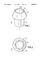
- FIG. 1is a perspective view of the inventive piston seal.
- FIG. 2is a top view thereof.
- FIG. 3is an operational view of the piston seal showing the same at the beginning of a low pressure phase (return stroke) of a pneumatic engine work cycle.
- FIG. 4is an operational view of the piston seal showing the same at the beginning of a high pressure (compression stroke) phase of the engine work cycle.
- FIG. 5is a view, similar to the view of FIG. 4, however showing the entire piston, piston seal, cylinder and air inlet assembly.
- FIG. 6is a view, similar to the view of FIG. 5, however showing the piston in its comparison stroke, however advanced twenty degrees within the engine cycle from the position of FIG. 5.
- FIG. 7is a system view, similar to the views of FIGS. 5 and 6, however showing the piston and associated seal in a low pressure phase of the engine cycle corresponding to that of FIG. 3.
- FIG. 8is a system view similar to that of FIGS. 5 through 7, however, showing a near-completed down or return stroke of the system, in which a high pressure phase had not yet been reached.
- an inventive piston seal 10may be seen to include a substantially cylindrical sleeve 12 including, integrally dependent from a radial base 14, an annular skirt 16.
- said cylindrical sleeve 12 and annular skirt 16are polarly symmetric about a longitudinal axis 18 thereof, also referred to herein as a system axis.
- the transverse width of skirt 16is about one-half the width or thickness of the sleeve 12.
- FIG. 2A top view of the seal is shown in FIG. 2.
- FIG. 3includes a cross-sectional view of a piston cylinder 20 of a pneumatic engine and a piston 22 which is proportioned for complemental travel therewith.
- the systemalso includes a piston rod 24 which comprises means for effecting the axial reciprocation of the piston 22 within the piston cylinder 20.
- the illustrated pistonconstitutes but one of numerous geometries to which the present invention is applicable.
- FIG. 3further shows a radial compression surface 26 of said piston 22.
- said piston seal 10is complementally or, otherwise as by bonding means, secured.
- the interior diameter of cylindrical sleeve 12 of the seal 10 as well as radial base 14 thereofwill be secured, this leaving only resilient annular skirt 16 without direct securement to compression surface 26 of the piston 22.
- skirt 16 of seal 10is normally biased inwardly toward system.
- axis 18such that, during a low pressure phase or return stroke of the work cycle (which is shown in FIG. 3) of the pneumatic engine, skirt 16 will exhibit the geometry shown therein. That is, skirt 16 will not touch interior wall 30 of the piston cylinder 20. In the view of FIG. 3, this geometry is shown permits the escape of air 32 through cylinder aperture 34.
- the piston and piston sealare lower within piston cylinder 20 and are moving upward relative to bottom surface 36 of the piston cylinder. See FIG. 4.
- high pressure air bursts 38 and 38acreate a high pressure region 40 within cylinder 20 thereby applying sufficient axial and radial pressure against the underside of skirt 16 to overcome said inward bias.
- the upper surface of skirt 16will deformably urge against wall 30 of the cylinder thereby creating a high pressure, high integrity annular seal within region 42, between said surface 30 of cylinder 20, said skirt 16 of seal 10 and an annular interface region 44 of the piston 22.
- FIG. 5a view of an entire piston, cylinder and associated air inlet 45 assembly for a pneumatic engine to which the present invention is applicable.
- FIG. 5(which corresponds to that of FIG. 4) show a high compression phase of the engine work cycle, that is, the part of the work cycle during which piston 22 is moving upward but has not yet reached cylinder apertures 34 through which air is released.
- inlet ball 46is closed relative to cylinder inlet 48.
- spring 50which rests on rod 52, is shown in the process of pushing off of ball 46 to impart kinetic energy to piston 22.
- FIG. 7corresponds to that of FIG. 3.
- This phase of the work cyclecorresponds to the point of lowest internal compression within the cylinder 20, i.e., the return stroke.
- FIG. 8is shown the downward motion of piston 22, however, before sufficient pressure has been reached within region 40 to overcome the inward bias of piston seal skirt 16 toward axis 18 of the system. Accordingly, during the phases of the work cycle shown in FIGS. 7 and 8, the skirt 16 maintains its normally closed inward biased (also shown in FIG. 1), thereby permitting escape of air within region 40 in order to release back pressure that would otherwise develop therein. Thereby, maximum engine efficiency is obtained.
Landscapes
- Engineering & Computer Science (AREA)
- Mechanical Engineering (AREA)
- General Engineering & Computer Science (AREA)
- Pistons, Piston Rings, And Cylinders (AREA)
- Compressor (AREA)
- Compressors, Vaccum Pumps And Other Relevant Systems (AREA)
Abstract
Description
Claims (1)
Priority Applications (8)
| Application Number | Priority Date | Filing Date | Title |
|---|---|---|---|
| US09/363,023US6085631A (en) | 1998-10-26 | 1999-07-29 | Piston-to-cylinder seal for a pneumatic engine |
| NZ337744ANZ337744A (en) | 1998-10-26 | 1999-09-09 | Piston-to-cylinder seal for a pneumatic engine with pressure dependent, variable sealing diameter |
| US09/613,569US6230605B1 (en) | 1998-10-26 | 2000-07-10 | Piston-to-cylinder seal for a pneumatic engine |
| EP00115440AEP1072756A3 (en) | 1999-07-29 | 2000-07-18 | Piston-to-cylinder seal for a pneumatic engine |
| PCT/US2000/020388WO2001009489A1 (en) | 1999-07-29 | 2000-07-27 | Piston-to-cylinder seal for a pneumatic engine |
| AU63804/00AAU767524B2 (en) | 1999-07-29 | 2000-07-27 | Piston-to-cylinder seal for a pneumatic engine |
| CNB008123136ACN1189645C (en) | 1999-07-29 | 2000-07-27 | Piston-to-cylinder seals for pneumatic engines and method of sealing pistons in cylinders |
| US09/756,299US20020002902A1 (en) | 1998-10-26 | 2001-01-09 | Piston-to-cylinder seal for a pneumatic engine |
Applications Claiming Priority (2)
| Application Number | Priority Date | Filing Date | Title |
|---|---|---|---|
| US09/178,595US6006517A (en) | 1998-04-09 | 1998-10-26 | Pneumatic engine |
| US09/363,023US6085631A (en) | 1998-10-26 | 1999-07-29 | Piston-to-cylinder seal for a pneumatic engine |
Related Parent Applications (1)
| Application Number | Title | Priority Date | Filing Date |
|---|---|---|---|
| US09/178,595Continuation-In-PartUS6006517A (en) | 1998-04-09 | 1998-10-26 | Pneumatic engine |
Related Child Applications (1)
| Application Number | Title | Priority Date | Filing Date |
|---|---|---|---|
| US09/613,569ContinuationUS6230605B1 (en) | 1998-10-26 | 2000-07-10 | Piston-to-cylinder seal for a pneumatic engine |
Publications (1)
| Publication Number | Publication Date |
|---|---|
| US6085631Atrue US6085631A (en) | 2000-07-11 |
Family
ID=23428461
Family Applications (1)
| Application Number | Title | Priority Date | Filing Date |
|---|---|---|---|
| US09/363,023Expired - LifetimeUS6085631A (en) | 1998-10-26 | 1999-07-29 | Piston-to-cylinder seal for a pneumatic engine |
Country Status (5)
| Country | Link |
|---|---|
| US (1) | US6085631A (en) |
| EP (1) | EP1072756A3 (en) |
| CN (1) | CN1189645C (en) |
| AU (1) | AU767524B2 (en) |
| WO (1) | WO2001009489A1 (en) |
Cited By (6)
| Publication number | Priority date | Publication date | Assignee | Title |
|---|---|---|---|---|
| US6230605B1 (en)* | 1998-10-26 | 2001-05-15 | Spin Master Toys | Piston-to-cylinder seal for a pneumatic engine |
| US6511493B1 (en) | 2000-01-10 | 2003-01-28 | Hydrocision, Inc. | Liquid jet-powered surgical instruments |
| US20030088259A1 (en)* | 2001-08-08 | 2003-05-08 | Staid Kevin P | Medical device with high pressure quick disconnect handpiece |
| US6626079B1 (en) | 2002-03-28 | 2003-09-30 | Rehco, Llc | Pneumatic motor |
| US20040200924A1 (en)* | 2003-01-29 | 2004-10-14 | Clark Leonard R. | Radio-controlled flying toy |
| US7717685B2 (en) | 2001-04-27 | 2010-05-18 | Hydrocision, Inc. | High pressure pumping cartridges for medical and surgical pumping and infusion applications |
Families Citing this family (1)
| Publication number | Priority date | Publication date | Assignee | Title |
|---|---|---|---|---|
| US9618116B2 (en) | 2013-08-27 | 2017-04-11 | Illinois Tool Works Inc. | Ported piston for automatic nailer |
Citations (8)
| Publication number | Priority date | Publication date | Assignee | Title |
|---|---|---|---|---|
| US29497A (en)* | 1860-08-07 | Improvement in seeding-machines | ||
| US2846190A (en)* | 1952-02-29 | 1958-08-05 | Schlumberger Well Surv Corp | Hydraulic devices |
| USRE29497E (en) | 1972-06-24 | 1977-12-20 | Stabilus Gmbh | Piston rod seal for adjustable pneumatic spring |
| JPS5644408A (en)* | 1979-09-19 | 1981-04-23 | Tomy Kogyo Co Inc | Engine for toy and model |
| US4355564A (en)* | 1979-03-30 | 1982-10-26 | Atlas Copco Aktiebolag | Pneumatic reciprocating mechanism |
| US5042365A (en)* | 1983-08-15 | 1991-08-27 | Rockwell International Corporation | Annular preloaded seal for a sliding piston in cylindrical tank |
| US5079997A (en)* | 1989-07-27 | 1992-01-14 | Korea Institute Of Science And Technology | Piston seal device for a pneumatic cylinder |
| US5558117A (en)* | 1995-01-11 | 1996-09-24 | Mcguinness; Frank J. | Pneumatic valve assembly with dynamic annular seal flange |
Family Cites Families (2)
| Publication number | Priority date | Publication date | Assignee | Title |
|---|---|---|---|---|
| IT1214182B (en)* | 1987-05-07 | 1990-01-10 | Caenazzo Alessandro Pasqualott | FLUID MICROMOTOR. |
| US6006517A (en)* | 1998-04-09 | 1999-12-28 | Spin Master Toys, Ltd. | Pneumatic engine |
- 1999
- 1999-07-29USUS09/363,023patent/US6085631A/ennot_activeExpired - Lifetime
- 2000
- 2000-07-18EPEP00115440Apatent/EP1072756A3/ennot_activeWithdrawn
- 2000-07-27AUAU63804/00Apatent/AU767524B2/ennot_activeCeased
- 2000-07-27WOPCT/US2000/020388patent/WO2001009489A1/enactiveIP Right Grant
- 2000-07-27CNCNB008123136Apatent/CN1189645C/ennot_activeExpired - Lifetime
Patent Citations (8)
| Publication number | Priority date | Publication date | Assignee | Title |
|---|---|---|---|---|
| US29497A (en)* | 1860-08-07 | Improvement in seeding-machines | ||
| US2846190A (en)* | 1952-02-29 | 1958-08-05 | Schlumberger Well Surv Corp | Hydraulic devices |
| USRE29497E (en) | 1972-06-24 | 1977-12-20 | Stabilus Gmbh | Piston rod seal for adjustable pneumatic spring |
| US4355564A (en)* | 1979-03-30 | 1982-10-26 | Atlas Copco Aktiebolag | Pneumatic reciprocating mechanism |
| JPS5644408A (en)* | 1979-09-19 | 1981-04-23 | Tomy Kogyo Co Inc | Engine for toy and model |
| US5042365A (en)* | 1983-08-15 | 1991-08-27 | Rockwell International Corporation | Annular preloaded seal for a sliding piston in cylindrical tank |
| US5079997A (en)* | 1989-07-27 | 1992-01-14 | Korea Institute Of Science And Technology | Piston seal device for a pneumatic cylinder |
| US5558117A (en)* | 1995-01-11 | 1996-09-24 | Mcguinness; Frank J. | Pneumatic valve assembly with dynamic annular seal flange |
Cited By (15)
| Publication number | Priority date | Publication date | Assignee | Title |
|---|---|---|---|---|
| US6230605B1 (en)* | 1998-10-26 | 2001-05-15 | Spin Master Toys | Piston-to-cylinder seal for a pneumatic engine |
| US6511493B1 (en) | 2000-01-10 | 2003-01-28 | Hydrocision, Inc. | Liquid jet-powered surgical instruments |
| US6669710B2 (en) | 2000-01-10 | 2003-12-30 | Hydrocision, Inc. | Liquid jet-powered surgical instruments |
| US8851866B2 (en) | 2001-04-27 | 2014-10-07 | Hydrocision, Inc. | Methods and apparatuses for joining a pumping cartridge to a pump drive |
| US7717685B2 (en) | 2001-04-27 | 2010-05-18 | Hydrocision, Inc. | High pressure pumping cartridges for medical and surgical pumping and infusion applications |
| US6923792B2 (en) | 2001-08-08 | 2005-08-02 | Hydrocision, Inc. | Medical device with high pressure quick disconnect handpiece |
| US20030088259A1 (en)* | 2001-08-08 | 2003-05-08 | Staid Kevin P | Medical device with high pressure quick disconnect handpiece |
| US7951107B2 (en) | 2001-08-08 | 2011-05-31 | Hydrocision, Inc. | Medical device with high pressure quick disconnect handpiece |
| US20050267443A1 (en)* | 2001-08-08 | 2005-12-01 | Hydrocision, Inc. | Medical device with high pressure quick disconnect handpiece |
| US6626079B1 (en) | 2002-03-28 | 2003-09-30 | Rehco, Llc | Pneumatic motor |
| US6862973B2 (en) | 2002-03-28 | 2005-03-08 | Rehco, Llc | Pneumatic motor |
| AU2003216471B2 (en)* | 2002-03-28 | 2006-09-07 | Rehco, Llc | Pneumatic motor |
| US20040060429A1 (en)* | 2002-03-28 | 2004-04-01 | Jeffrey Rehkemper | Pneumatic motor |
| WO2003083271A1 (en) | 2002-03-28 | 2003-10-09 | Rehco, Llc | Pneumatic motor |
| US20040200924A1 (en)* | 2003-01-29 | 2004-10-14 | Clark Leonard R. | Radio-controlled flying toy |
Also Published As
| Publication number | Publication date |
|---|---|
| CN1189645C (en) | 2005-02-16 |
| EP1072756A3 (en) | 2002-03-20 |
| WO2001009489A1 (en) | 2001-02-08 |
| CN1371448A (en) | 2002-09-25 |
| AU6380400A (en) | 2001-02-19 |
| AU767524B2 (en) | 2003-11-13 |
| EP1072756A2 (en) | 2001-01-31 |
Similar Documents
| Publication | Publication Date | Title |
|---|---|---|
| US6085631A (en) | Piston-to-cylinder seal for a pneumatic engine | |
| EP1082550B1 (en) | Pneumatic engine | |
| JPS6325379A (en) | Piston pump | |
| US3830347A (en) | Shock absorber and dirt shield therefor | |
| US6230605B1 (en) | Piston-to-cylinder seal for a pneumatic engine | |
| CN208605537U (en) | A kind of novel dual damping Liquid and gas damper | |
| HK1036645A (en) | Piston-to-cylinder seal for a pneumatic engine | |
| US20030209013A1 (en) | Piston air engine | |
| KR880004251A (en) | Air spring with inner sealing band and installation method | |
| CN209615399U (en) | A kind of energy conservation travelling valve arrangement | |
| EP0289806B1 (en) | Fluid-operated miniature engine | |
| JPH0430353Y2 (en) | ||
| JP2617954B2 (en) | Cushion packing for pressure cylinder | |
| RU2003794C1 (en) | Air-operated hammer with throttle air manifold | |
| JPS6120345Y2 (en) | ||
| KR100489424B1 (en) | Sealing device of gas filling part at the gas shock absorber | |
| EP1803894B1 (en) | Pneumatic motor | |
| JPS5918201Y2 (en) | gas compressor piston ring | |
| JPH0550263U (en) | Valve mechanism | |
| JPS5985419A (en) | pump assembly | |
| JPH0143564Y2 (en) | ||
| JPH0654964U (en) | Sealing device for reciprocating motion | |
| JPH055339Y2 (en) | ||
| JP2517399Y2 (en) | Rodless cylinder device | |
| KR850700060A (en) | Internal combustion engine with dynamic variable compression ratio |
Legal Events
| Date | Code | Title | Description |
|---|---|---|---|
| AS | Assignment | Owner name:SPIN MASTER TOYS, LTD., CANADA Free format text:ASSIGNMENT OF ASSIGNORS INTEREST;ASSIGNOR:KOWNACKI, CHARLES D.;REEL/FRAME:010739/0039 Effective date:19991215 | |
| STCF | Information on status: patent grant | Free format text:PATENTED CASE | |
| AS | Assignment | Owner name:SPIN MASTER TOYS, CANADA Free format text:ASSIGNMENT OF ASSIGNORS INTEREST;ASSIGNOR:KOWNACKI, CHARLES D.;REEL/FRAME:011284/0818 Effective date:20001113 | |
| AS | Assignment | Owner name:SPIN MASTER TOYS, ONTARIO Free format text:CORRECTIVE ASSIGNMENT REEL 010739 FRAME 0039;ASSIGNOR:KOWNACKI, CHARLES D.;REEL/FRAME:013386/0352 Effective date:19991215 Owner name:SPIN MASTER LTD., CANADA Free format text:ASSIGNMENT OF ASSIGNORS INTEREST;ASSIGNOR:SPIN MASTER TOYS;REEL/FRAME:013380/0919 Effective date:20021010 | |
| FPAY | Fee payment | Year of fee payment:4 | |
| FPAY | Fee payment | Year of fee payment:8 | |
| FEPP | Fee payment procedure | Free format text:PAT HOLDER NO LONGER CLAIMS SMALL ENTITY STATUS, ENTITY STATUS SET TO UNDISCOUNTED (ORIGINAL EVENT CODE: STOL); ENTITY STATUS OF PATENT OWNER: LARGE ENTITY | |
| FPAY | Fee payment | Year of fee payment:12 |