US6085350A - Single event upset tolerant system and method - Google Patents
Single event upset tolerant system and methodDownload PDFInfo
- Publication number
- US6085350A US6085350AUS09/034,282US3428298AUS6085350AUS 6085350 AUS6085350 AUS 6085350AUS 3428298 AUS3428298 AUS 3428298AUS 6085350 AUS6085350 AUS 6085350A
- Authority
- US
- United States
- Prior art keywords
- output
- upset
- signal
- voted
- input
- Prior art date
- Legal status (The legal status is an assumption and is not a legal conclusion. Google has not performed a legal analysis and makes no representation as to the accuracy of the status listed.)
- Expired - Fee Related
Links
Images


Classifications
- G—PHYSICS
- G06—COMPUTING OR CALCULATING; COUNTING
- G06F—ELECTRIC DIGITAL DATA PROCESSING
- G06F11/00—Error detection; Error correction; Monitoring
- G06F11/07—Responding to the occurrence of a fault, e.g. fault tolerance
- G06F11/16—Error detection or correction of the data by redundancy in hardware
- G06F11/18—Error detection or correction of the data by redundancy in hardware using passive fault-masking of the redundant circuits
- G06F11/183—Error detection or correction of the data by redundancy in hardware using passive fault-masking of the redundant circuits by voting, the voting not being performed by the redundant components
- G06F11/184—Error detection or correction of the data by redundancy in hardware using passive fault-masking of the redundant circuits by voting, the voting not being performed by the redundant components where the redundant components implement processing functionality
- G06F11/185—Error detection or correction of the data by redundancy in hardware using passive fault-masking of the redundant circuits by voting, the voting not being performed by the redundant components where the redundant components implement processing functionality and the voting is itself performed redundantly
- G—PHYSICS
- G06—COMPUTING OR CALCULATING; COUNTING
- G06F—ELECTRIC DIGITAL DATA PROCESSING
- G06F11/00—Error detection; Error correction; Monitoring
- G06F11/07—Responding to the occurrence of a fault, e.g. fault tolerance
- G06F11/16—Error detection or correction of the data by redundancy in hardware
- G06F11/18—Error detection or correction of the data by redundancy in hardware using passive fault-masking of the redundant circuits
- G06F11/187—Voting techniques
Definitions
- This inventionrelates in general to the field of systems tolerant to radiation and, in particular, to systems tolerant to radiation induced single event upsets.
- SEUsingle event upset
- space borne applications having high speed communication ratesfrequently experience single event upsets in a high radiation environment.
- many space borne applications having high speed communicationsneed synchronization with ground equipment.
- Some applications needing synchronization with ground equipmentinclude direct-sequence spread spectrum systems, frequency hopping systems, and synchronous stream encryption systems.
- a significant problem with some space borne applications needing synchronization with ground equipmentoccurs when a system element, such as a pseudo-noise generator, experiences an single event upset due to radiation.
- GaAsgallium arsenide
- ECLemitter coupled logic
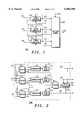
- FIG. 1is a simplified block diagram of an SEU tolerant system in accordance with a preferred embodiment of the present invention
- FIG. 2is a simplified block diagram of a decision element in accordance with a preferred embodiment of the present invention.
- FIG. 3is a simplified block diagram of a voter element in accordance with a preferred embodiment of the present invention.
- FIG. 4is a simplified block diagram of an output disabler element in accordance with a preferred embodiment of the present invention.
- FIG. 5is a simplified flow chart of a procedure for identifying and correcting an single event upset in accordance with a preferred embodiment of the present invention.
- the present inventionprovides a system and method tolerant to an SEU.
- the present inventionalso provides a system and method capable of maintaining synchronization between a transmitter and a receiver after experiencing an SEU.
- the present inventionalso provides a system and method which maintain continuous communications between a transmitter and a receiver following an SEU.
- the present inventionalso provides a voter system which is tolerant of hard failures.
- FIG. 1is a simplified block diagram of an SEU tolerant system in accordance with a preferred embodiment of the present invention.
- SEU tolerant system 100illustrates a system capable of identifying and correcting an SEU.
- SEU tolerant system 100includes signal generators 105 coupled to decision element 200 via outputs 120 and upset detected signals 125.
- each of signal generators 105accepts at least one of inputs 115 and generates at least one of outputs 120.
- inputs 115represent independent inputs
- outputs 120represent independent outputs.
- inputs 115represent red (e.g., plain text) data flowing into signal generators 105
- outputs 120represent black (e.g., encrypted text) flowing out of signal generators 105.
- upset detected signals 125represent an upset detected signal determined by decision element 200.
- voted output 130represents a single output from decision element 200.
- voted output 130is generated by decision element 200 and represents a majority voted output determined from outputs 120.
- signal generators 105represent redundant signal generators.
- signal generators 105receive inputs 115 and perform operations substantially simultaneously. Additionally, signal generators generate outputs 120 and receive outputs 120 as feedback.
- each signal generatoris preferably coupled to feedback from at least one other signal generator.
- each signal generatorincludes a selector (not shown) to select feedback (e.g., outputs 120) based on control information determined via an upset detected signal.
- signal generators 105represent encryptors for encrypting red (e.g., plain text) data into black (e.g., clear text) data.
- signal generators 105represent decryptors for decrypting black (e.g., encrypted text) data into red (e.g., plain text) data.
- signal generators 105represent pseudo-noise generators.
- signal generators 105rely on internal feedback (not shown) to determine an output, and therefore an SEU affects the internal state (e.g., sequence) of a signal generator.
- the present inventionprovides an apparatus and method for correcting the internal state of a signal generator experiencing an SEU by copying feedback from another signal generator.
- the present inventionprovides an apparatus and method for restoring the internal state of a signal generator experiencing an SEU. Additionally, when the internal state is corrected for the signal generator experiencing an SEU, the signal generator experiencing the SEU again receives its own internal feedback.
- FIG. 2is a simplified block diagram of a decision element in accordance with a preferred embodiment of the present invention.
- Decision element 200illustrates an apparatus for identifying and correcting an SEU.
- decision element 200includes voters 300, comparators 210, data stores 215, and output disabler 400.
- Decision element 200may be implemented in software; however, decision element 200 is preferably implemented using high speed logic such as differential GaAs and ECL.
- three voters 300receive outputs 120.
- Each of the three voters 300are preferably individually coupled to comparators 210.
- Voters 300preferably perform a majority voter operation on outputs 120.
- outputs 120are preferably generated via individual signal generators 105 (FIG. 1).
- intermediate voted outputs 315couple three voters 300 to three comparators 210.
- Each of comparators 210preferably receives at least one intermediate voted output 315 and at least one output 120 and performs a compare operation on each of the received pairs.
- Results of the comparisone.g., "1" or "0" are preferably stored in a corresponding one of data stores 215.
- data stores 215are coupled to comparators 210. Additionally, data stores 215 provide upset detected signals 125 based on comparisons between at least one of outputs 120 and intermediate voter outputs 315. In one embodiment, an external element may reset or force a data value from data stores 215 via resets 220.
- voter 301receives each of intermediate voted outputs 315 and performs another majority voter operation.
- voter 301generates a second intermediate voted output 316 similar to intermediate voted outputs 315.
- Second intermediate voted output 316couples voter 301 to output disabler 400.
- upset detected signals 125couple data stores 215 to output disabler 400.
- output disabler 400accepts second intermediate voted output 316 and determines when to inhibit second intermediate voted output 316 based on upset detected signals 125.
- output disabler 400inhibits second intermediate voted output 316 from appearing on voted output 130.
- other numbers of voters 300, voter 301, comparators 210, data stores 215, and output disabler 400may represent an apparatus for identifying and correcting an SEU.
- FIG. 3is a simplified block diagram of a voter element in accordance with a preferred embodiment of the present invention.
- this voter elementrepresents one of voters 300 (FIG. 2).
- a voter 300comprises two primary elements, exclusive-or gate 305 and selector 310.
- the voter shown in FIG. 3performs a majority voter operation.
- the voter shown in FIG. 3receives three inputs and provides one output.
- exclusive-or gate 305receives outputs 120 when coupled to an element other than a voter (e.g., signal generators 105 (FIG. 1)). Alternatively, exclusive-or gate 305 preferably receives intermediate voted outputs 315 when coupled to voters 300 (FIG. 2). Exclusive-or gate 305 performs a logical exclusive-or operation on received signals. Exclusive-or gate 305 provides a single output to selector 310.
- a votere.g., signal generators 105 (FIG. 1)
- exclusive-or gate 305preferably receives intermediate voted outputs 315 when coupled to voters 300 (FIG. 2).
- Exclusive-or gate 305performs a logical exclusive-or operation on received signals. Exclusive-or gate 305 provides a single output to selector 310.
- Selector 310receives outputs 120 when coupled to an element other than a voter (e.g., signal generators 105 (FIG. 1)). Alternatively, selector 310 receives intermediate voted outputs 315 when coupled to voters 300 (FIG. 2). Selector 310 is preferably controlled by a single output received from exclusive-or gate 305. A single output controls selector 310 to select one of two signals received by selector 310. Selector 310 preferably provides a single intermediate voted output similar to intermediate voted outputs 315 and second intermediate voted output 316.
- FIG. 4is a simplified block diagram of an output disabler element in accordance with a preferred embodiment of the present invention.
- Output disabler 400illustrates an apparatus for inhibiting second intermediate voted output 316 from being presented to output 130 when a majority of upset detected signals are asserted.
- output disabler 400is comprised of a plurality of gates 425-430.
- each of gates 425-430performs a logical AND operation.
- gate 425receives second intermediate voted output 316 from a voter.
- enable signal 410is determined by performing a logical AND operation via gate 426 on two independent upset detected signals 125 (e.g., a first and second upset detected signal).
- enable signal 415is determined by gate 427 based on two independent upset detected signals 125 (e.g., a second and third upset detected signal).
- enable signal 415controls intermediate voted output 317 between gate 425 and gate 429.
- enable signal 420is determined by gate 428 based on two independent upset detected signals 125 (e.g., a first and third upset detected signal).
- enable signal 420controls intermediate voted output 318 between gate 429 and gate 430.
- FIG. 5is a simplified flow chart of a procedure 500 for identifying and correcting an single event upset in accordance with a preferred embodiment of the present invention.
- procedure 500is performed by a decision element receiving redundant outputs from a plurality of signal generators.
- outputsare received from signal generators.
- outputs from a plurality of signal generatorsare received by a decision element.
- outputs from the plurality of signal generatorsare received substantially simultaneously.
- outputsare compared using first-level voters.
- a plurality of three votersperform a majority voting operation on three independent outputs from three independent, redundant signal generators.
- Each of the plurality of votersgenerates an intermediate voted output creating a preferred total of three intermediate voted outputs.
- a second compareis performed using a second-level voter.
- a voterperforms a majority voting operation using the three intermediate voted outputs determined in task 510.
- the majority voting operation performed in task 510generates a second intermediate voted output representing a majority of inputs received by the second-level voter.
- outputs from signal generatorsare compared with intermediate voted outputs from first-level voters to determine upset detected signals.
- outputs from signal generatorsare compared with intermediate voted outputs from first-level majority voters to determine upset detected signals.
- a comparatorasserts an upset detected signal.
- a comparatordoes not assert an upset detected signal.
- task 520is performed using three independent comparators receiving independent inputs and generating independent outputs.
- the voted outputis inhibited when a majority of upset detected signals are asserted.
- a majoritye.g., 2-of-3
- outputis inhibited from a decision element.
- outpute.g., second intermediate voted output (task 515)
- task 525is performed by an output disabler. In one embodiment of the present invention, task 525 is optional.
- task 530another check for upset detected signals is performed.
- a signal generatorreceives feedback from an output associated therewith, and then task 505 is performed.
- task 532is performed.
- an upset detected signalis provided to an upset one of the signal generators.
- an upset detected signalis asserted, an upset detected signal is returned to a corresponding signal generator.
- an upset detected signalis asserted until the signal generator experiencing an SEU produces an output corresponding to output from signal generators unaffected by an SEU.
- execution order of task 525is interchangeable with tasks 530-532.
- feedbackis selected for a signal generator associated with an single event upset.
- an associated signal generatorselects feedback from another signal generator.
- a signal generatorselects feedback from another signal generator while an associated upset detected signal is asserted.
- an output for the upset signal generatoris generated based on the input signal and the feedback signal.
- a signal generator experiencing an SEUreceives feedback from another signal generator (task 535). Additionally, each signal generator preferably receives input from a source external to the signal generator. Preferably, the signal generator experiencing an SEU generates an output based on the feedback from another signal generator and input from an external source. In a preferred embodiment, when the signal generator which experienced an SEU again produces an output corresponding to the output of signal generators unaffected by an SEU, the signal generator which experienced the SEU switches to receive feedback from its own output.
- a system and method tolerant to an SEUWhat has also been shown are a system and method capable of maintaining synchronization between a transmitter and a receiver after experiencing an SEU. What has also been shown are a system and method which maintain continuous communications between a transmitter and a receiver following an SEU. Also shown is a voter system which is tolerant of hard failures.
Landscapes
- Engineering & Computer Science (AREA)
- Theoretical Computer Science (AREA)
- Quality & Reliability (AREA)
- Physics & Mathematics (AREA)
- General Engineering & Computer Science (AREA)
- General Physics & Mathematics (AREA)
- Hardware Redundancy (AREA)
Abstract
Description
Claims (17)
Priority Applications (1)
| Application Number | Priority Date | Filing Date | Title |
|---|---|---|---|
| US09/034,282US6085350A (en) | 1998-03-04 | 1998-03-04 | Single event upset tolerant system and method |
Applications Claiming Priority (1)
| Application Number | Priority Date | Filing Date | Title |
|---|---|---|---|
| US09/034,282US6085350A (en) | 1998-03-04 | 1998-03-04 | Single event upset tolerant system and method |
Publications (1)
| Publication Number | Publication Date |
|---|---|
| US6085350Atrue US6085350A (en) | 2000-07-04 |
Family
ID=21875429
Family Applications (1)
| Application Number | Title | Priority Date | Filing Date |
|---|---|---|---|
| US09/034,282Expired - Fee RelatedUS6085350A (en) | 1998-03-04 | 1998-03-04 | Single event upset tolerant system and method |
Country Status (1)
| Country | Link |
|---|---|
| US (1) | US6085350A (en) |
Cited By (16)
| Publication number | Priority date | Publication date | Assignee | Title |
|---|---|---|---|---|
| US6637005B1 (en)* | 2000-02-29 | 2003-10-21 | Hughes Electronics Corporation | Triple redundant self-scrubbing integrated circuit |
| KR100402757B1 (en)* | 2001-08-22 | 2003-10-22 | 한국전자통신연구원 | Signal Processing Method and Module for Reliable System Considering Safety |
| KR100449232B1 (en)* | 2001-12-04 | 2004-09-18 | 한국전기연구원 | Method for voting a pulse for redundancy controllers |
| US20040195460A1 (en)* | 2003-01-23 | 2004-10-07 | Supercomputing System Ag | Fault tolerant computer controlled system |
| US20050278567A1 (en)* | 2004-06-15 | 2005-12-15 | Honeywell International Inc. | Redundant processing architecture for single fault tolerance |
| US20060036909A1 (en)* | 2004-08-13 | 2006-02-16 | Seakr Engineering, Incorporated | Soft error detection and recovery |
| US20060236168A1 (en)* | 2005-04-01 | 2006-10-19 | Honeywell International Inc. | System and method for dynamically optimizing performance and reliability of redundant processing systems |
| US7383479B1 (en)* | 2001-02-14 | 2008-06-03 | Xilinx, Inc. | Techniques for mitigating, detecting, and correcting single event upset effects in systems using SRAM-based field programmable gate arrays |
| US20110214043A1 (en)* | 2010-02-26 | 2011-09-01 | Honeywell International Inc. | High integrity data bus fault detection using multiple signal components |
| US8054208B2 (en) | 2010-03-30 | 2011-11-08 | Honeywell International Inc. | Re-configurable multipurpose analog interface |
| WO2011121414A3 (en)* | 2010-03-29 | 2011-12-01 | Nelson Mandela Metropolitan University | A method for mitigating single event upsets in sequential electronic circuits |
| US8390324B2 (en) | 2010-09-20 | 2013-03-05 | Honeywell International Inc. | Universal functionality module |
| US20140164839A1 (en)* | 2011-08-24 | 2014-06-12 | Tadanobu Toba | Programmable device, method for reconfiguring programmable device, and electronic device |
| US8782299B2 (en) | 2010-04-27 | 2014-07-15 | Honeywell International Inc. | Re-configurable multi-purpose digital interface |
| US9092621B2 (en) | 2012-07-12 | 2015-07-28 | Samsung Electronics Co., Ltd. | Method of detecting fault attack |
| US10956265B2 (en) | 2015-02-03 | 2021-03-23 | Hamilton Sundstrand Corporation | Method of performing single event upset testing |
Citations (4)
| Publication number | Priority date | Publication date | Assignee | Title |
|---|---|---|---|---|
| US5297052A (en)* | 1989-10-16 | 1994-03-22 | The Boeing Company | Integrated fault-tolerant air data inertial reference system |
| US5537583A (en)* | 1994-10-11 | 1996-07-16 | The Boeing Company | Method and apparatus for a fault tolerant clock with dynamic reconfiguration |
| US5630046A (en)* | 1995-01-27 | 1997-05-13 | Sextant Avionique | Fault-tolerant computer architecture |
| US5903717A (en)* | 1997-04-02 | 1999-05-11 | General Dynamics Information Systems, Inc. | Fault tolerant computer system |
- 1998
- 1998-03-04USUS09/034,282patent/US6085350A/ennot_activeExpired - Fee Related
Patent Citations (4)
| Publication number | Priority date | Publication date | Assignee | Title |
|---|---|---|---|---|
| US5297052A (en)* | 1989-10-16 | 1994-03-22 | The Boeing Company | Integrated fault-tolerant air data inertial reference system |
| US5537583A (en)* | 1994-10-11 | 1996-07-16 | The Boeing Company | Method and apparatus for a fault tolerant clock with dynamic reconfiguration |
| US5630046A (en)* | 1995-01-27 | 1997-05-13 | Sextant Avionique | Fault-tolerant computer architecture |
| US5903717A (en)* | 1997-04-02 | 1999-05-11 | General Dynamics Information Systems, Inc. | Fault tolerant computer system |
Cited By (23)
| Publication number | Priority date | Publication date | Assignee | Title |
|---|---|---|---|---|
| US6637005B1 (en)* | 2000-02-29 | 2003-10-21 | Hughes Electronics Corporation | Triple redundant self-scrubbing integrated circuit |
| US7620883B1 (en) | 2001-02-14 | 2009-11-17 | Xilinx, Inc. | Techniques for mitigating, detecting, and correcting single event upset effects |
| US7383479B1 (en)* | 2001-02-14 | 2008-06-03 | Xilinx, Inc. | Techniques for mitigating, detecting, and correcting single event upset effects in systems using SRAM-based field programmable gate arrays |
| KR100402757B1 (en)* | 2001-08-22 | 2003-10-22 | 한국전자통신연구원 | Signal Processing Method and Module for Reliable System Considering Safety |
| KR100449232B1 (en)* | 2001-12-04 | 2004-09-18 | 한국전기연구원 | Method for voting a pulse for redundancy controllers |
| US20040195460A1 (en)* | 2003-01-23 | 2004-10-07 | Supercomputing System Ag | Fault tolerant computer controlled system |
| US7263630B2 (en)* | 2003-01-23 | 2007-08-28 | Supercomputing System Ag | Fault tolerant computer controlled system |
| AU2004200226B2 (en)* | 2003-01-23 | 2008-10-30 | Supercomputing System Ag | Fault tolerant computer controlled system |
| CN100363899C (en)* | 2003-01-23 | 2008-01-23 | 超级计算系统股份公司 | Fault tolerant computer controlled system |
| US7392426B2 (en)* | 2004-06-15 | 2008-06-24 | Honeywell International Inc. | Redundant processing architecture for single fault tolerance |
| US20050278567A1 (en)* | 2004-06-15 | 2005-12-15 | Honeywell International Inc. | Redundant processing architecture for single fault tolerance |
| US20060036909A1 (en)* | 2004-08-13 | 2006-02-16 | Seakr Engineering, Incorporated | Soft error detection and recovery |
| US7263631B2 (en) | 2004-08-13 | 2007-08-28 | Seakr Engineering, Incorporated | Soft error detection and recovery |
| US20060236168A1 (en)* | 2005-04-01 | 2006-10-19 | Honeywell International Inc. | System and method for dynamically optimizing performance and reliability of redundant processing systems |
| US20110214043A1 (en)* | 2010-02-26 | 2011-09-01 | Honeywell International Inc. | High integrity data bus fault detection using multiple signal components |
| US8365024B2 (en) | 2010-02-26 | 2013-01-29 | Honeywell International Inc. | High integrity data bus fault detection using multiple signal components |
| WO2011121414A3 (en)* | 2010-03-29 | 2011-12-01 | Nelson Mandela Metropolitan University | A method for mitigating single event upsets in sequential electronic circuits |
| US8054208B2 (en) | 2010-03-30 | 2011-11-08 | Honeywell International Inc. | Re-configurable multipurpose analog interface |
| US8782299B2 (en) | 2010-04-27 | 2014-07-15 | Honeywell International Inc. | Re-configurable multi-purpose digital interface |
| US8390324B2 (en) | 2010-09-20 | 2013-03-05 | Honeywell International Inc. | Universal functionality module |
| US20140164839A1 (en)* | 2011-08-24 | 2014-06-12 | Tadanobu Toba | Programmable device, method for reconfiguring programmable device, and electronic device |
| US9092621B2 (en) | 2012-07-12 | 2015-07-28 | Samsung Electronics Co., Ltd. | Method of detecting fault attack |
| US10956265B2 (en) | 2015-02-03 | 2021-03-23 | Hamilton Sundstrand Corporation | Method of performing single event upset testing |
Similar Documents
| Publication | Publication Date | Title |
|---|---|---|
| US6085350A (en) | Single event upset tolerant system and method | |
| US5440633A (en) | Communication network access method and system | |
| US7133524B2 (en) | Key installation system, LSI for implementing the same, and key installation method | |
| US4926475A (en) | Data encryption key failure monitor | |
| EP0711051B1 (en) | Data processing system with verification of authenticity of cryptographic algorithms according to the challenge/response principle | |
| US6408389B2 (en) | System for supporting secured log-in of multiple users into a plurality of computers using combined presentation of memorized password and transportable passport record | |
| Zhang et al. | Stealthy integrity attacks for a class of nonlinear cyber-physical systems | |
| US10826943B2 (en) | Security controller | |
| US11343266B2 (en) | Self-certified security for assured cyber-physical systems | |
| US5822431A (en) | Virtual authentication network for secure processors | |
| US5958073A (en) | Reliability enhanced processing system and method for optimizing | |
| US9485225B2 (en) | Method for manufacturing a filtering module | |
| US20220078021A1 (en) | Aerospace advanced chain of trust | |
| KR20140043537A (en) | Secure communication apparatus and method for securing scada communication network | |
| US20220067175A1 (en) | Encryption converter | |
| US20220156153A1 (en) | Method for controlling other systems based on single-point execution contract | |
| US5101373A (en) | System and method for securing remote terminal and remote terminal program | |
| US10955830B2 (en) | Systems and methods for designing and securing edge data processing pipelines | |
| Kolybelnikov | Trust model, reliability theory in theory of secrecy | |
| US5655021A (en) | Method for checking data sequences | |
| CN114615075B (en) | Software tamper-proof system and method of controller and storage medium | |
| CN116132094B (en) | A method, device, equipment and readable storage medium for docking system services | |
| Valdivia et al. | Coexistence of safety and security: Synchronized redundant system with security enhancements | |
| Zhu et al. | Side-Channel Attack Counter-measure Analysis for Control and Diagnostics Applications | |
| Killmann | The History of the Development and the Analysis of the Cipher Machine T-310/50 and the Procedure ARGON by the ZCO |
Legal Events
| Date | Code | Title | Description |
|---|---|---|---|
| AS | Assignment | Owner name:MOTOROLA, INC., ILLINOIS Free format text:ASSIGNMENT OF ASSIGNORS INTEREST;ASSIGNORS:EMMERT, STEVEN ROBERT;HANDLY, PAUL ROBERT;COMER, ERWIN PERRY;AND OTHERS;REEL/FRAME:009063/0382 Effective date:19980226 | |
| AS | Assignment | Owner name:GENERAL DYNAMICS DECISION SYSTEMS, INC., ARIZONA Free format text:ASSIGNMENT OF ASSIGNORS INTEREST;ASSIGNOR:MOTOROLA, INC.;REEL/FRAME:012435/0219 Effective date:20010928 | |
| FEPP | Fee payment procedure | Free format text:PAYOR NUMBER ASSIGNED (ORIGINAL EVENT CODE: ASPN); ENTITY STATUS OF PATENT OWNER: LARGE ENTITY | |
| FPAY | Fee payment | Year of fee payment:4 | |
| REMI | Maintenance fee reminder mailed | ||
| AS | Assignment | Owner name:VOICE SIGNALS LLC, NEVADA Free format text:ASSIGNMENT OF ASSIGNORS INTEREST;ASSIGNOR:GENERAL DYNAMICS C4 SYSTEMS, INC.;REEL/FRAME:017154/0330 Effective date:20050725 | |
| AS | Assignment | Owner name:GENERAL DYNAMICS C4 SYSTEMS, INC., VIRGINIA Free format text:MERGER;ASSIGNOR:GENERAL DYNAMICS DECISION SYSTEMS, INC.;REEL/FRAME:018480/0321 Effective date:20041217 | |
| FEPP | Fee payment procedure | Free format text:PAYER NUMBER DE-ASSIGNED (ORIGINAL EVENT CODE: RMPN); ENTITY STATUS OF PATENT OWNER: LARGE ENTITY Free format text:PAYOR NUMBER ASSIGNED (ORIGINAL EVENT CODE: ASPN); ENTITY STATUS OF PATENT OWNER: LARGE ENTITY | |
| FPAY | Fee payment | Year of fee payment:8 | |
| REMI | Maintenance fee reminder mailed | ||
| LAPS | Lapse for failure to pay maintenance fees | ||
| LAPS | Lapse for failure to pay maintenance fees | Free format text:PATENT EXPIRED FOR FAILURE TO PAY MAINTENANCE FEES (ORIGINAL EVENT CODE: EXP.); ENTITY STATUS OF PATENT OWNER: LARGE ENTITY | |
| STCH | Information on status: patent discontinuation | Free format text:PATENT EXPIRED DUE TO NONPAYMENT OF MAINTENANCE FEES UNDER 37 CFR 1.362 | |
| FP | Lapsed due to failure to pay maintenance fee | Effective date:20120704 | |
| AS | Assignment | Owner name:HANGER SOLUTIONS, LLC, GEORGIA Free format text:ASSIGNMENT OF ASSIGNORS INTEREST;ASSIGNOR:INTELLECTUAL VENTURES ASSETS 161 LLC;REEL/FRAME:052159/0509 Effective date:20191206 |