US6084768A - Non-operational shock protection for disk carriers in a high density package - Google Patents
Non-operational shock protection for disk carriers in a high density packageDownload PDFInfo
- Publication number
- US6084768A US6084768AUS09/094,817US9481798AUS6084768AUS 6084768 AUS6084768 AUS 6084768AUS 9481798 AUS9481798 AUS 9481798AUS 6084768 AUS6084768 AUS 6084768A
- Authority
- US
- United States
- Prior art keywords
- carrier
- disk drive
- data storage
- top side
- assembly
- Prior art date
- Legal status (The legal status is an assumption and is not a legal conclusion. Google has not performed a legal analysis and makes no representation as to the accuracy of the status listed.)
- Expired - Lifetime
Links
Images


Classifications
- G—PHYSICS
- G11—INFORMATION STORAGE
- G11B—INFORMATION STORAGE BASED ON RELATIVE MOVEMENT BETWEEN RECORD CARRIER AND TRANSDUCER
- G11B33/00—Constructional parts, details or accessories not provided for in the other groups of this subclass
- G11B33/12—Disposition of constructional parts in the apparatus, e.g. of power supply, of modules
- G11B33/125—Disposition of constructional parts in the apparatus, e.g. of power supply, of modules the apparatus comprising a plurality of recording/reproducing devices, e.g. modular arrangements, arrays of disc drives
- G11B33/127—Mounting arrangements of constructional parts onto a chassis
- G11B33/128—Mounting arrangements of constructional parts onto a chassis of the plurality of recording/reproducing devices, e.g. disk drives, onto a chassis
- G—PHYSICS
- G06—COMPUTING OR CALCULATING; COUNTING
- G06F—ELECTRIC DIGITAL DATA PROCESSING
- G06F1/00—Details not covered by groups G06F3/00 - G06F13/00 and G06F21/00
- G06F1/16—Constructional details or arrangements
- G06F1/18—Packaging or power distribution
- G06F1/183—Internal mounting support structures, e.g. for printed circuit boards, internal connecting means
- G06F1/184—Mounting of motherboards
- G—PHYSICS
- G06—COMPUTING OR CALCULATING; COUNTING
- G06F—ELECTRIC DIGITAL DATA PROCESSING
- G06F1/00—Details not covered by groups G06F3/00 - G06F13/00 and G06F21/00
- G06F1/16—Constructional details or arrangements
- G06F1/18—Packaging or power distribution
- G06F1/183—Internal mounting support structures, e.g. for printed circuit boards, internal connecting means
- G06F1/187—Mounting of fixed and removable disk drives
- G—PHYSICS
- G11—INFORMATION STORAGE
- G11B—INFORMATION STORAGE BASED ON RELATIVE MOVEMENT BETWEEN RECORD CARRIER AND TRANSDUCER
- G11B33/00—Constructional parts, details or accessories not provided for in the other groups of this subclass
- G11B33/02—Cabinets; Cases; Stands; Disposition of apparatus therein or thereon
- G11B33/022—Cases
- G—PHYSICS
- G11—INFORMATION STORAGE
- G11B—INFORMATION STORAGE BASED ON RELATIVE MOVEMENT BETWEEN RECORD CARRIER AND TRANSDUCER
- G11B33/00—Constructional parts, details or accessories not provided for in the other groups of this subclass
- G11B33/02—Cabinets; Cases; Stands; Disposition of apparatus therein or thereon
- G11B33/08—Insulation or absorption of undesired vibrations or sounds
Definitions
- the present inventiongenerally relates to the mounting and support of hard disk drives for computers and, in a preferred embodiment thereof, more particularly relates to apparatus for removably supporting a plurality of hot plug-connected hard disk drives.
- Hard disk drives for a file server or other type of computerare often mounted, in a vertically or horizontally stacked array, in a rectangular sheet metal "cage" structure which may be disposed within the computer housing or externally thereto.
- each disk driveis typically "hot plug” connected within the cage. This type of electrical connection permits any of the supported disk drives to be removed and re-installed within the cage without disturbing the operation of the other disk drives.
- each disk driveis typically supported on a carrier structure which is slidably and removably insertable into the cage to mate an electrical connector carried on a rear portion of the drive or its carrier structure with a corresponding electrical connector on a back plane circuit board suitably supported at the rear interior side of the cage.
- a computer systemwhich includes a CPU unit having a microprocessor and a data storage section operative to store data retrievable by the microprocessor.
- the data storage sectionincludes a housing structure in which a series of device/carrier assemblies are disposed in a closely stacked array.
- Each assemblyincludes a carrier structure removably supported by the housing structure, and a data storage, representatively a hot-pluggable hard disk drive, mounted on the carrier structure.
- Each adjacent pair of device/carrier assemblies in the closely stacked array thereofhave facing first and second side portions.
- the first side portionhas a recessed area thereon
- the second side portionrepresentatively a bottom side of one of the assemblies, has a spaced plurality of resilient shock absorbing feet projecting outwardly therefrom and nestingly received in the recessed area of the facing first side portion of the other assembly.
- the resilient shock absorbing feet on the bottom of the carrier portion of the assemblyare positioned horizontally outwardly of the horizontal periphery of the disk drive that the carrier supports, the feet are arranged in spaced pairs of feet positioned outwardly adjacent opposite sides of the disk drive, and the recessed area is defined by two vertical recesses on the top side of the assembly on these opposite sides of the disk drive. Accordingly, the pairs of resilient shock absorbing feet on each assembly nest in these two recess areas on the top side of the assembly immediately below the feet.
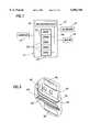
- FIG. 1is a schematic diagram of a representative computer system having incorporated therein a stacked hard disk drive/carrier array supported in a cage structure and embodying principles of the present invention
- FIG. 2is a simplified, partially exploded perspective view of the cage structure and the plurality of disk drive/carrier assemblies operatively supported therein and hot plug-connected to backplane electrical connectors therein, with one of the disk drive/carrier assemblies having been removed from the cage structure;
- FIG. 3is an enlarged scale perspective detail view of an inner side portion of one of the vertical side walls of the cage structure
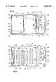
- FIG. 4is an enlarged scale top plan view of the removed disk drive/carrier assembly
- FIG. 5is an enlarged scale bottom plan view of the removed disk drive/carrier assembly
- FIG. 6is an enlarged scale front end elevational view of the removed disk drive/carrier assembly
- FIG. 7is an enlarged scale rear end elevational view of the removed disk drive/carrier assembly
- FIG. 8is an enlarged scale right side elevational view of the removed disk drive/carrier assembly
- FIG. 9is an enlarged scale left side elevational view of the removed disk drive/carrier assembly
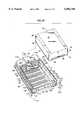
- FIG. 10is an enlarged scale exploded top, rear and right side perspective view of the removed disk drive/carrier assembly, with opposite heat sink wall portions of the carrier being pivoted outwardly to their disk drive release positions relative to a base wall portion of the carrier, and portions of the assembly having been removed for purposes of illustrative clarity;
- FIGS. 11-13are enlarged scale top, front and left side perspective views of the removed disk drive/carrier assembly, with a latch portion thereof respectively being in closed, partially opened, and fully opened positions thereof;
- FIGS. 11A-13Aare enlarged scale partial cross-sectional views through the removed disk drive/carrier assembly respectively taken along lines 11A--11A, 12A--12A and 13A--13A of FIGS. 11-13;
- FIG. 14is an enlarged scale, partially cut away perspective view of part of the carrier portion of the removed assembly and illustrates a fiber optic cable-based LED indicating light transfer structure integrally incorporated into the carrier;
- FIG. 15is an enlarged scale partial exploded perspective view of the removed disk drive/carrier assembly and illustrates a heat sink support structure feature thereof;
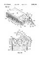
- FIG. 16is an enlarged scale cross-sectional view through one of the cage-supported disk drive/carrier assemblies taken along line 16--16 of FIG. 2;
- FIG. 17is an enlarged scale front side elevational view of the cage structure and illustrates two of the disk drive/carrier assemblies supported and hot plug-connected therein;
- FIG. 18is an enlarged scale detail view of the dashed circled area "A" in FIG. 17.
- FIG. 1Schematically illustrated in FIG. 1 is a representative computer system 10, the components of which are interconnected as shown and include a computer, illustratively in the form of a tower type CPU unit 12; a monitor 14; a keyboard 16; and a pointing device, representatively in the form of a mouse 18.
- the CPU unit 12has a data storage section, representatively a vertically stacked series of hard disk drives 20, operative to store data that may be retrieved by a microprocessor 22 within the CPU unit 12.
- the vertically stacked series of hard disk drives 20are removably positioned within a support housing, representatively in the form of a sheet metal cage structure 24 positioned within the outer housing 26 of the CPU unit 12, using specially designed carrier apparatus embodying principles of the present invention and subsequently described herein.
- the cage structure 24could be located externally of the CPU housing 26 within a separate rack housing (not shown).
- the disk drives 20have been representatively illustrated as being vertically stacked, they could also be positioned in a horizontally stacked array in which the cage 24 was rotated ninety degrees to one side instead of being vertically oriented.
- the data storage section of the computer system 10, with its vertically stacked array of hard disk drives 20(representatively five in number), is shown in simplified, partially exploded perspective form in FIG. 2.
- the sheet metal cage structure 24functions as a support housing and representatively is of a vertically elongated rectangular configuration, having an open front side 28, top and bottom walls 30 and 32, left and right vertical side walls 34 and 36, and a backplane structure 38 extending along its rear side. Ventilation holes 40 are formed in the top, left and right cage walls 30,34 and 36, and a schematically illustrated fan 42 is operatively disposed behind the backplane structure 38 within the computer housing 26.
- the fan 42draws cooling air 44 into the interior of the cage structure 24 through its open front side 28 and its ventilation holes 40, flows the air 44 along the disk drives 20 supported within the cage 24, and then discharges the air outwardly through the rear of the cage 24 around the periphery of the backplane structure 38.
- the backplane structure 38has a vertically elongated rectangular configuration, with a front side 46 from which a vertically spaced array of five male electrical connectors 48 (one for each of the five disk drives 20) forwardly project. To the left of each of the connectors 48 are three vertically stacked LED indicating lights 50,52 and 54. AS later described herein, these indicating lights are used to provide a visual indicia as to the operating state of each of the hard disk drives 20.
- Each of the disk drives 20is supported on a specially designed carrier structure 60 which is used, as later described herein, to removably support the disk drives 20 within the cage 24 in a manner creating a hot plug connection for each drive to one of the backplane connectors 48.
- portions 62 of the vertical left and right side walls 34,36 of the cage 24are lanced inwardly to form for each carrier 60 a pair of front and rear guide rail sections 64 on each of the left and right cage side walls 34 and 36 (see FIGS. 3 and 16-18), with each of the guide rail sections 64 being defined by vertically facing pairs of the lanced-in cage wall portions 62.
- each front pair of lanced-in wall portions 62is an arcuate lanced-in wall portion 66.
- Each disk drive 20(see FIGS. 10 and 15) has a generally rectangular configuration which is elongated in a front-to-rear direction, and further has front and rear end walls 68 and 70, top and bottom side walls 72 and 74, and left and right vertical side walls 76 and 78.
- a pair of threaded mounting holes 80,82are formed near the bottom side of the disk drive respectively adjacent respectively adjacent its front and rear ends
- a circuit board 84is operatively mounted on the bottom side of the disk drive 20, and is electrically coupled thereto.
- the circuit board 84which forms a portion of the overall disk drive structure, has a female SCA connector 86 thereon which is centrally positioned at the rear end wall 70 of the disk drive and is releasably mateable, in a hot-plug manner, with a corresponding one of the backplane connectors 48 (see FIGS. 2 and 16) in response to operative insertion of the disk drive 20 into the cage 24 as later described herein.
- the carrier structures 60are used to support the hard disk drives 20 for removable sliding insertion into the interior cage 24 to supported operating positions in which the disk drives are releasably hot-plugged to the backplane connectors 48 received in the SCA connectors 86 of the inserted disk drives 20.
- Each carrier structure 60is of a unitary, no loose parts construction comprised of several components that are captively retained on one another so that none of the components can be separated from the structure and become misplaced, lost or easily damaged.
- each of the disk drive carriers 60includes a perforated sheet metal bottom or base wall 90; left and right metal side wall heat sink structures 92 and 94; a molded plastic front bezel structure 96; and a molded plastic ejector latch assembly 98.
- Base wall 90has front and rear end edges 100 and 102, left and right side edges 104 and 106, and an upturned rear end flange 108 having a rectangular opening 110 therein.
- Each of the left and right metal side wall heat sink structures 92 and 94extends upwardly from its associated base wall 90 and has a relatively thin rectangular body section 114 which is horizontally elongated in a front-to-rear direction relative to the base wall 90 and is positioned adjacent one of the left and right base wall side edges 104,106.
- the outer sides of the left and right side body sections 114have formed thereon vertically spaced pluralities of elongated heat sink fin projections 116 that longitudinally extend in front-to-rear directions.
- each of the left and right side walls 92,94is an outwardly projecting mounting flange 118 which is slidingly receivable in the previously mentioned cage guide rail sections 64 to mount the carrier 60 (and thus the disk drive 20 which it supports) within the cage 24.
- Front and rear disk drive mounting screws 120,122are captively retained on each of the body sections 114 and extend therethrough from their outer sides to their inner sides 124.
- just forwardly of the front mounting screws 120are a pair of outwardly projecting boss structures 126 formed on the outer sides of the left and right carrier side wall body sections 114.
- flanges 128, elongated in a front-to-rear directions,are formed on the top side edges of the body sections 114.
- each of the side wall body sections 114is an inturned tab 130 having a horizontal slot 132 formed therein. Top end portions 112a of the upturned base wall rear corner tabs 112 are slidingly received in the slots 132 which are substantially wider in left-to-right directions than the corresponding widths of the top tab end portions 112a.
- the side wall body sections 114have inturned transverse front end portions 114a each defined by a vertically spaced series of separated heat sink fins 134 joined at their inner ends by a vertical bar member 136.
- Front and rear resilient shock isolation feet 137a,137bare suitably secured to the underside of each of the side wall body sections 114 and project downwardly beyond its bottom side surface.
- Feet 137a,137bhave rectangular configurations which are elongated in front-to-rear directions, with the feet 137a being positioned adjacent the junctures of the body sections 114 and their associated transverse front end portions, and the feet 137b being positioned adjacent the rear ends of the body sections 114.
- the molded plastic bezel structure 96(see FIGS. 5, 6, 10 and 14) is positioned at the front end of the carrier 60 and has a hollow rectangular central section 138 with an open rear side 140 and a front wall 142 with a rectangular opening 144 therein.
- a translucent plastic plate member 146 with disk operating icons 148,150,152 thereonis received in the opening 144.
- a bottom base plate portion 154 of the bezelwhich is elongated in left and right directions and underlies a front end edge portion of the metal carrier base wall 90.
- a spaced series of postsextend upwardly from the bezel base plate portion 154 through corresponding holes in the metal carrier base plate 90 and are heat staked thereto as at 156.
- Hollow bosses 158,160are respectively formed on left and right sides of the central bezel section 138 and are respectively received between the two lowermost heat sink fins 134 on the transverse front end portions 114a of the left and right heat sink walls 92,94 of the carrier 60. Shouldered screws 162 extend vertically through the front end portions 114a, and the bosses 158,160, and secure the front end portions 114a to the bezel 96 for pivotal motion relative thereto about vertical axes extending through the bosses 158,160.
- the ejector latch assembly 98(see FIGS. 11-13A) includes an elongated molded plastic ejector lever member 164; a molded plastic retainer slide member 166; and a molded plastic bifurcated spring member 168.
- the ejector lever member 164has an inner end portion 170 with an inner side recess 172 formed therein, and a generally transverse, rearwardly inturned outer end portion 174 having an outer side notch 176 disposed at its juncture with the balance of the lever member.
- the retainer slide member 166is formed integrally with an elongated spring arm structure 178 which, in turn, is formed integrally with a left side of the central bezel section 138 and extends between the two lowermost heat sink fins 134 on the left front corner of the carrier 60. AS illustrated, the retainer slide member 166 is exposed on a left front side portion of the carrier 60.
- the bifurcated spring member 168has an elongated inner side arm 180, an elongated outer side arm 182 with a rounded projection 184 at its outer end, and an inner end portion 186 with a notch 188 formed therein. Inner end portions of the ejector lever 164 and the bifurcated spring member 168 are positioned between the two lowermost heat sink fins 134 on a right front corner portion of the carrier 60 and are pivotally secured to such heat sink fins 134 by a vertically extending shouldered screw 190.
- the spring member 168is pivotable relative to the lever member 164 in a manner such that the outer side arm 182 can swing into and out of the lever side recess 172, and the outer end of the inner side arm 180 is forwardly adjacent the boss 160.
- the notched inner end portion 186 of the ejector lever member 164projects outwardly beyond a right front corner portion of the carrier 60 in a rightward direction.
- a rearwardly facing exposed optical connector 192is suitably mounted on the left rear corner of the carrier 60 in a cutout area 194 of the left inturned side wall tab 130.
- the connector 192extends forwardly through the cutout area 194 into a vertically enlarged portion of a horizontally elongated groove 196 formed in the inner side surface 124 of the body section 114 of the left heat sink side wall 92.
- Three fiber optic cables 198,200,202are operatively coupled at rear ends thereof to the connector 192 and longitudinally extend therefrom through the groove 196 to adjacent its front end near the front end section 114a of the left side wall heat sink structure 92.
- the fiber optic cables 198,200,202turn rightwardly to a location directly behind the open rear side 140 of the central bezel section 138.
- the cablesthen turn forwardly and connect to a lens structure 204 disposed within the interior of the central bezel section 138.
- Lens structure 204has three spaced apart, forwardly projecting sections 206,208,210 which are respectively associated with the front ends of the fiber optic cables 198,200,202.
- the lens sections 206,208,210have front ends which are located behind the plastic plate member 145 and respectively aligned with the drive operating icons 148,150,152 thereon (see FIG. 6).
- each of the carriers 60also includes a pair of thermally conductive resilient heat transfer interface pad members 212 having horizontally elongated configurations. Pads 212 are adhered to the inner sides 124 of the side wall body sections 114, with the left pad 212 being mounted over the groove 196 in the left body section 114. Holes 120a,122a are formed in the pads 212 to permit passage of the captively retained mounting screws 120,122 therethrough.
- the rear ends of the left and right side wall heat sink structures 92,94are pivoted outwardly away from one another and the opposite left and right side edges 104,106 of the base wall 90, as indicated by the arrows 214 in FIG. 10, to thereby increase the distance between the inner side surfaces 124 of the body sections 114.
- the two side wall portions 92,94pivot horizontally about the vertical shouldered screws 162 at the front of the carrier 60 (see FIG. 11A), with the engagement of the rear corner tabs 112 with the inner end surfaces of the tab slots 132 serving to limit the extent of this outward pivoting.
- the disk drive 20is then simply placed atop the base wall 90 so that the disk drive threaded mounting holes 80,82 are aligned with the front and rear mounting screws 120,122 captively retained on the left and right side wall structures 92 and 94.
- the side walls 92 and 94are then pivoted back toward one another to their positions shown in FIGS. 4 and 5 in which they are parallel to the left and right side edges of the base wall 90.
- the mounting screws 120,122are simply screwed into the corresponding opposing disk drive side openings 80 and 82.
- This simple proceduresecurely mounts the disk drive 20 in the carrier 60 in a manner such that the bottom, opposite sides and opposite ends of the mounted disk drive are shielded by portions of the carrier structure against user hand contact with the mounted disk drive, while at the same time providing an appreciable degree of ESD shielding for the disk drive 20.
- the completed disk drive/carrier assembly 20,60may then be operatively inserted into the cage 24 (see FIG. 2) as later described herein.
- the removal of the disk drive 20 from its carrieris effected simply by unscrewing the mounting screws 120,122 from the disk drive 20, pivoting the carrier side wall structures 92,94 outwardly to their FIG. 10 release positions to facilitate removal of the disk drive, and then simply lifting the now freed disk drive 20 off of the top side of the base wall 90.
- both the installation of the disk drive 20 on its associated carrier 60, and the subsequent removal of the disk drive 20 from its carrier 60,can be carried out without the removal of any portion of the carrier 60 from the balance thereof. This is due to the unique "no loose parts" construction of the carrier 60 in which all of its components are captively carried by the balance of the carrier.
- the front ends of the side wall structures 92,94are captively and movably retained on the bezel 96
- the rear ends of the side wall structures 92,94are captively and movably retained on the base wall 90
- the bezel 96is captively retained on the base wall 90
- the latch assembly 98is captively and movably retained on the bezel 96 and the right side wall structure 94
- the mounting screws 120,122are captively and movably retained on the left and right carrier side wall portions 92 and 94.
- Each of the disk drive/carrier assembliesmay be operatively installed within the interior of the cage 24 (see FIG. 2) by simply sliding the carrier mounting flanges 118 rearwardly into the appropriate opposing pairs of cage guide rail sections 64 (see FIGS. 3, 16 and 18), and then using the carrier's ejector latch assembly 98 to releasably mate, in a hot-plugged manner, the disk drive's rear-mounted SCA connector 86 (see FIGS. 10 and 15) with a facing one of the backplane connectors 48 (see FIGS. 2 and 16).
- the operation of the specially designed ejector latch assembly 98will now be described with reference to FIGS. 11-13A.
- FIGS. 11 and 11AOne of the disk drive/carrier assemblies 20,60 is shown in FIGS. 11 and 11A with its ejector latch assembly 98 in its fully closed, locked position to which it is moved, after the carrier 60 is slid into the cage 24, to mate the disk drive/backplane connector pair 86,48 and releasably lock the disk drive/carrier assembly 20/60 in its operative position within the cage 24.
- the ejector lever member 164longitudinally extends in a left-to-right direction and is compactly positioned closely adjacent the front side of the central bezel section 138, with the inturned outer end portion 174 of the lever member 164 being received between the lowermost pair of heat sink fins 134 on the left front corner of the carrier 60.
- the outer end of the inner side arm 180 of the bifurcated spring member 168is in abutment with the boss 160, and the outer side arm 182 is received within the inner side recess 172 of the outer side arm 182.
- the outer end projection 184 of the outer side arm 182is engaging the front side surface of the recess 172 in a manner rearwardly bending the outer side arm 182, thereby exerting a resilient forward pivotal biasing force on the ejector lever member 164.
- the forwardly biased ejector lever member 164is prevented from forwardly pivoting away from its fully closed position shown in FIGS.
- the retainer slide member 166a portion of which forwardly overlies the outer side notch area 176 at the outer end of the lever member 164 and releasably blocks forward pivoting of the lever member 164 relative to the front end of the carrier 60.
- the inner or right end 186 of the bifurcated spring member 168, adjacent the notch 188 therein,is received within an immediately adjacent vertical channel portion 36a of the right side wall 36 of the cage 24 (see FIG. 2).
- the userWhen it is desired to remove the inserted disk drive/carrier assembly 20,60 from the interior of the cage 24, and unplug the disk drive connector 86 from its associated backplane connector 48, the user simply moves the retainer slide member 166 leftwardly, as indicated by the arrows 216 in FIGS. 11 and 11A, thereby leftwardly bending the spring arm structure 178 and shifting the retainer slide member 166 out of overlying, blocking engagement with the left end of the ejector lever member 164.
- the lever member 164engages and rearwardly bends the outer spring side arm 182, and the curved outer side surface 222 of the lever member outer end portion 174 engages and leftwardly cams the retainer slide member 166 (thus leftwardly bending the spring arm structure 178) to permit the lever member end portion 174 to enter the space between the two lowermost heat sink fins 134 on the left front corner of the carrier 60.
- the resiliently deformed spring arm structure 178causes the retainer slide member 166 to snap rightwardly back into the outer end notch 176 of the lever member 164 to releasably retain the lever member 164 in its closed position, shown in FIGS. 11 and 11A, against the forward pivotal biasing force of the resiliently deformed outer side arm 182 of the bifurcated spring member 168.
- the overall ejector latch assembly 98is of a simple, relatively inexpensive construction, and is easily useable with one hand, in a quite intuitive manner, to latch and unlatch the carrier 60 to and from the cage 24 and couple and decouple the connector pair 48,86.
- the ejector latch assembly 98 in its closed orientationis also quite compact, but opens outwardly to define an easily graspable pull handle structure. While the ejector latch assembly 98 has been illustrated as being associated with a disk drive structure it could be alternatively utilized with a variety of other types of pluggable devices such as, by way of example, circuit boards and CD ROM drives.
- the carrier 60is provided with several other advantages over conventionally configured carrier structures used to operatively support disk drives in support housings such as sheet metal cages.
- One of these additional advantagesis the provision of substantially improved dissipation of disk drive operating heat.
- the pivotable opposite side wall portions 92,94 of the carrier 60are configured as heat sink structures, having integral fin portions 116,134 thereon.
- the operation of the fan 42draws cooling air 44 inwardly through the front carrier fins 134 and along the supported disk drive, and inwardly through the cage ventilation holes 40 along the disk drive 20 and the carrier side wall cooling fins 116 to convectively dissipate disk drive operating heat from the disk drive/carrier assembly 20,60.
- This convective heat dissipationis very substantially augmented by the provision of the heat conductive thermal interface pad members 212 (see FIGS. 10 and 15) which are compressed between the carrier side wall members 92,94 and the facing left and right sides 76,78 of the disk drive 20.
- the use of these pads 212substantially increases the conductive heat transfer between the supported disk drive and the heat sink side wall portions 92,94 of the carrier 60 to thereby increase the overall disk drive operating heat transfer to the cooling flow of air 44 rearwardly through the interior of the support cage structure 24.
- the carrier structure 60provides a visual indication of the operational state of the disk drive 20 that it removably supports within the cage 24.
- the circuitry associated with the drive 20i.e., the electronics on its underlying circuit board portion 84
- the circuitry associated with the drive 20activates the three LED indicating lights 50,52,54 leftwardly adjacent the backplane connector 48 (see FIGS. 2 and 14) in accordance with the operational state of the disk drive 20.
- any of the three indicating lights 50,52,54When any of the three indicating lights 50,52,54 is activated, its light output is received by the optical connector 192 on the left rear corner of the carrier 60 and transmitted via the associated one of the three fiber optic cables 198,200,202 to the lens structure 204 at the front of the carrier 60 and then to the associated one of the three drive operating icons 148,150,152 via one of the lens sections 206,208,210 disposed in a central front end portion of the carrier 60.
- the unique positioning of the light transmitting elements 200,202,204 within the interior of the carrier 60, as opposed to being routed externally along the outer side thereof or on the cage structure 24,provides this transfer of the LED indicating light signals without increasing the outer spatial envelope of the carrier 60 or adding the complexity of placing the transfer elements on the cage structure. Additionally, due to the use of fiber optic cables as the light transmitting elements, neither the required bends in the elements to accommodate the central placement of the operating icons 148,150,152 nor the length of the transmitting element runs from the LED lights 50,52,54 to the operating icons 148,150,152 appreciably diminishes the light output intensity at the operating icons.
- the hard disk drives 20 supported by the carriers 60are high speed drives that operate in the 7,200 RPM to 12,000 RPM rotational speed range.
- This speed rangerefers to the rotational speed range of the platter portion of each drive around a rotational axis 224 of the drive (see FIG. 16) which is transverse to the base wall 90 of the carrier 60.
- this high rotational speedtends to cause self-induced rotational vibration of the drive about the axis 224 as indicated by the double-ended arrow 226 in FIG. 16. If not suitably controlled, this rotational vibration 226 about the axis 224 can substantially degrade the performance of the supported disk drive 20.
- the self-induced rotational vibratory forces of its supported hard disk drive 20 about the axis 224are very substantially reduced by using the two boss structures 126 on opposite sides of the carrier 60 (see FIGS. 16 and 17) to create on the cage-inserted carrier 60 two oppositely disposed interference fits between the boss structures 126 and the lanced-in carrier side wall portions 66 in response to insertion of the carrier 60 into the cage 24 as previously described herein.
- Non-operational shock damageAnother potential source of damage to the disk drives 20 arises from what is commonly referred to as non-operational shock damage.
- This type of shock damage to one of the carrier-supported disk drives 20can arise when the carrier is removed from the cage 24 and placed on a horizontal work surface such as a table or work bench. For example, if the removed carrier accidentally slips out of a technician's hand and falls only a short distance onto the surface, or is placed on edge on the surface and then tips over onto the surface, the carrier-supported drive can be damaged from this type of non-operational shock.
- the configurations of the disk drive/carrier assemblies 20,60are related to one another in a unique manner permitting the previously described vibration isolation feet 137a,137b (see FIGS. 5-9, 17 and 18) to be placed on the bottom sides of the carriers 60 without appreciably increasing the overall stack height of a stacked array of disk drive/carrier assemblies 20,60 within the cage structure 24.
- each disk drive/carrier-assembly 20,60is configured in a manner such that the top side edges of the top edge flanges 128 on the left and right carrier side wall structures 92,94 are downwardly offset from the top side of the disk drive 20 supported in the carrier 60 to thereby create in the assembly 20,60 front-to-rear extending depressed areas 228 (see FIGS. 17 and 18) outwardly adjacent top right and left corner portions of the supported disk drive 20.
- These depressed areas 228define what may be termed nesting areas that downwardly receive the resilient support feet 137a,137b on the bottom side of the upwardly adjacent carrier 20.
- the support feet 137a,137b on the bottom side of the upper disk drive/carrier assembly 20,60a shown in FIGS. 17 and 18downwardly nest in the opposite top corner depressed areas 228 of the lower disk drive/carrier assembly 20,60b, with the bottom sides of the support feet 137a,137b on the upper disk drive/carrier assembly 20,60a being downwardly offset from the top side of the top side of the lower disk drive 20.
- each vertically successive pair of disk drive/carrier assemblies 20,60the resilient shock absorbing feet 137a,137b in the upper assembly are received and nest within the outer spatial envelope of the lower assembly so that the desirable presence of the shock absorbing feet 137a,137b does not appreciably increase the stack height of the multi-disk drive array. While this unique nesting of the support feet has been representatively illustrated and described in conjunction with a vertically stacked array of carrier-supported disk drives, it will be readily appreciated that it could also be utilized to advantage in conjunction with a horizontally stacked array of carrier-supported disk drives as well.
Landscapes
- Engineering & Computer Science (AREA)
- Theoretical Computer Science (AREA)
- Computer Hardware Design (AREA)
- Power Engineering (AREA)
- Human Computer Interaction (AREA)
- Physics & Mathematics (AREA)
- General Engineering & Computer Science (AREA)
- General Physics & Mathematics (AREA)
- Casings For Electric Apparatus (AREA)
Abstract
Description
Claims (16)
Priority Applications (1)
| Application Number | Priority Date | Filing Date | Title |
|---|---|---|---|
| US09/094,817US6084768A (en) | 1998-06-15 | 1998-06-15 | Non-operational shock protection for disk carriers in a high density package |
Applications Claiming Priority (1)
| Application Number | Priority Date | Filing Date | Title |
|---|---|---|---|
| US09/094,817US6084768A (en) | 1998-06-15 | 1998-06-15 | Non-operational shock protection for disk carriers in a high density package |
Publications (1)
| Publication Number | Publication Date |
|---|---|
| US6084768Atrue US6084768A (en) | 2000-07-04 |
Family
ID=22247357
Family Applications (1)
| Application Number | Title | Priority Date | Filing Date |
|---|---|---|---|
| US09/094,817Expired - LifetimeUS6084768A (en) | 1998-06-15 | 1998-06-15 | Non-operational shock protection for disk carriers in a high density package |
Country Status (1)
| Country | Link |
|---|---|
| US (1) | US6084768A (en) |
Cited By (68)
| Publication number | Priority date | Publication date | Assignee | Title |
|---|---|---|---|---|
| US6231224B1 (en) | 1999-09-22 | 2001-05-15 | International Business Machines Corporation | Light pipe guide and carrier for hard disk drive |
| US6373696B1 (en)* | 1998-06-15 | 2002-04-16 | Compaq Computer Corporation | Hard drive cooling using finned heat sink and thermally conductive interface pad |
| US6445587B1 (en)* | 2000-09-13 | 2002-09-03 | Storage Technology Corporation | Disk drive vibration/shock attenuation system and method |
| US6487081B2 (en) | 2000-12-29 | 2002-11-26 | Compaq Information Technologies Group, L.P. | Hard disk drive mounting system and method |
| US6490153B1 (en)* | 1999-08-06 | 2002-12-03 | California Digital Corporation | Computer system for highly-dense mounting of system components |
| US6525933B2 (en) | 2001-01-31 | 2003-02-25 | Hewlett-Packard Company | Computer peripheral mounting bracket |
| US6614653B2 (en)* | 2001-10-03 | 2003-09-02 | International Business Machines Corporation | Disk drive insertion tool and method |
| US6633481B2 (en) | 2001-07-12 | 2003-10-14 | Storage Technology Corporation | Media drive vibration attenuation system and method |
| EP1333442A3 (en)* | 2002-02-05 | 2004-01-28 | Quantum Corporation | Thermal cooling system for densely packed storage devices |
| US20040264116A1 (en)* | 2003-06-27 | 2004-12-30 | Rumney Gary Simon | Mounting arrangement for demountable units |
| US6856513B1 (en)* | 2003-03-31 | 2005-02-15 | Sun Microsystems, Inc. | Media drive mount |
| US6894893B2 (en)* | 1999-03-10 | 2005-05-17 | Fujitsu Limited | Electronic apparatus |
| US20050117288A1 (en)* | 2003-12-01 | 2005-06-02 | Imation Corp. | Data storage cartridge with hard drive and alignment feature |
| WO2004095256A3 (en)* | 2003-04-11 | 2005-07-07 | Raytheon Co | System and method for transferring large amounts of stored data |
| US20050207059A1 (en)* | 2004-03-19 | 2005-09-22 | Cochrane Paul D | Life extension in hard disk drives through virbration and thermal dampening using polymer springs |
| WO2005092045A3 (en)* | 2004-03-19 | 2006-05-04 | Stealthdrive Llc | Hard disk drive vibration damening using polymer springs |
| US20070127202A1 (en)* | 2005-12-01 | 2007-06-07 | Xyratex Technology Limited | Data storage device carrier and carrier tray |
| US20070211423A1 (en)* | 2006-03-08 | 2007-09-13 | Tsung-Chi Huang | Data access device and holder thereof |
| US20080259554A1 (en)* | 2007-04-17 | 2008-10-23 | Hong Fu Jin Precision Industry (Shenzhen) Co., Ltd. | Mounting apparatus for storage device |
| US7626810B1 (en)* | 2007-05-24 | 2009-12-01 | Netapp, Inc. | Apparatus and method for inhibiting high-frequency, electromagnetic interference from non-metallic hard disk drive carriers |
| US7778031B1 (en) | 2009-07-15 | 2010-08-17 | Teradyne, Inc. | Test slot cooling system for a storage device testing system |
| US7848106B2 (en) | 2008-04-17 | 2010-12-07 | Teradyne, Inc. | Temperature control within disk drive testing systems |
| US7890207B2 (en) | 2008-04-17 | 2011-02-15 | Teradyne, Inc. | Transferring storage devices within storage device testing systems |
| US7904211B2 (en) | 2008-04-17 | 2011-03-08 | Teradyne, Inc. | Dependent temperature control within disk drive testing systems |
| US7908029B2 (en) | 2008-06-03 | 2011-03-15 | Teradyne, Inc. | Processing storage devices |
| US7911778B2 (en) | 2008-04-17 | 2011-03-22 | Teradyne, Inc. | Vibration isolation within disk drive testing systems |
| US7929303B1 (en) | 2010-02-02 | 2011-04-19 | Teradyne, Inc. | Storage device testing system cooling |
| US7932734B2 (en) | 2009-07-15 | 2011-04-26 | Teradyne, Inc. | Individually heating storage devices in a testing system |
| US7940529B2 (en) | 2009-07-15 | 2011-05-10 | Teradyne, Inc. | Storage device temperature sensing |
| US7945424B2 (en) | 2008-04-17 | 2011-05-17 | Teradyne, Inc. | Disk drive emulator and method of use thereof |
| US7987018B2 (en) | 2008-04-17 | 2011-07-26 | Teradyne, Inc. | Transferring disk drives within disk drive testing systems |
| US7996174B2 (en) | 2007-12-18 | 2011-08-09 | Teradyne, Inc. | Disk drive testing |
| US8041449B2 (en) | 2008-04-17 | 2011-10-18 | Teradyne, Inc. | Bulk feeding disk drives to disk drive testing systems |
| US8102173B2 (en) | 2008-04-17 | 2012-01-24 | Teradyne, Inc. | Thermal control system for test slot of test rack for disk drive testing system with thermoelectric device and a cooling conduit |
| US8116079B2 (en) | 2009-07-15 | 2012-02-14 | Teradyne, Inc. | Storage device testing system cooling |
| US8238099B2 (en) | 2008-04-17 | 2012-08-07 | Teradyne, Inc. | Enclosed operating area for disk drive testing systems |
| US8405971B2 (en) | 2007-12-18 | 2013-03-26 | Teradyne, Inc. | Disk drive transport, clamping and testing |
| US8482915B2 (en) | 2008-04-17 | 2013-07-09 | Teradyne, Inc. | Temperature control within disk drive testing systems |
| US8514561B2 (en)* | 2010-12-07 | 2013-08-20 | Hong Fu Jin Precision Industry (Shenzhen) Co., Ltd. | Locking mechanism and information handling system using the same |
| US8547123B2 (en) | 2009-07-15 | 2013-10-01 | Teradyne, Inc. | Storage device testing system with a conductive heating assembly |
| US8628239B2 (en) | 2009-07-15 | 2014-01-14 | Teradyne, Inc. | Storage device temperature sensing |
| US8687349B2 (en) | 2010-07-21 | 2014-04-01 | Teradyne, Inc. | Bulk transfer of storage devices using manual loading |
| US9001456B2 (en) | 2010-08-31 | 2015-04-07 | Teradyne, Inc. | Engaging test slots |
| GB2527176A (en)* | 2014-06-13 | 2015-12-16 | Chris Hagan | Download booths |
| US20160125706A1 (en)* | 2014-10-30 | 2016-05-05 | International Business Machines Corporation | Indicator module for modular computing units |
| US9459312B2 (en) | 2013-04-10 | 2016-10-04 | Teradyne, Inc. | Electronic assembly test system |
| US9513677B2 (en) | 2014-03-18 | 2016-12-06 | Western Digital Technologies, Inc. | Shaped backplane for receiving electrical components |
| US9594409B1 (en)* | 2015-03-18 | 2017-03-14 | Western Digital Technologies, Inc. | Storage drive heat sink mounting structure |
| US20170094822A1 (en)* | 2015-09-24 | 2017-03-30 | Quanta Computer Inc. | Electronic device enclosure with an access mechanism |
| US9743547B1 (en) | 2016-04-19 | 2017-08-22 | Western Digital Technologies, Inc. | Switchable mechanical constraint for electrical connector with compliant mounting |
| US9779780B2 (en) | 2010-06-17 | 2017-10-03 | Teradyne, Inc. | Damping vibrations within storage device testing systems |
| US9785206B2 (en)* | 2013-01-29 | 2017-10-10 | Netgear, Inc. | Method and apparatus for housing a hard-disk drive using a tray with anchoring strips |
| US9823712B2 (en) | 2014-03-18 | 2017-11-21 | Western Digital Technologies, Inc. | Backplane for receiving electrical components |
| US10096344B2 (en)* | 2017-01-11 | 2018-10-09 | Fujitsu Limited | Holding frame for electronic device |
| US10546617B2 (en) | 2017-11-20 | 2020-01-28 | Western Digital Technologies, Inc. | Alternately shaped backplane for receiving electrical components |
| US10725091B2 (en) | 2017-08-28 | 2020-07-28 | Teradyne, Inc. | Automated test system having multiple stages |
| US10775408B2 (en) | 2018-08-20 | 2020-09-15 | Teradyne, Inc. | System for testing devices inside of carriers |
| US10845410B2 (en) | 2017-08-28 | 2020-11-24 | Teradyne, Inc. | Automated test system having orthogonal robots |
| US10948534B2 (en) | 2017-08-28 | 2021-03-16 | Teradyne, Inc. | Automated test system employing robotics |
| US10983145B2 (en) | 2018-04-24 | 2021-04-20 | Teradyne, Inc. | System for testing devices inside of carriers |
| US11226390B2 (en) | 2017-08-28 | 2022-01-18 | Teradyne, Inc. | Calibration process for an automated test system |
| US11754622B2 (en) | 2020-10-22 | 2023-09-12 | Teradyne, Inc. | Thermal control system for an automated test system |
| US11754596B2 (en) | 2020-10-22 | 2023-09-12 | Teradyne, Inc. | Test site configuration in an automated test system |
| US11867749B2 (en) | 2020-10-22 | 2024-01-09 | Teradyne, Inc. | Vision system for an automated test system |
| US11899042B2 (en) | 2020-10-22 | 2024-02-13 | Teradyne, Inc. | Automated test system |
| US11953519B2 (en) | 2020-10-22 | 2024-04-09 | Teradyne, Inc. | Modular automated test system |
| US20240168528A1 (en)* | 2022-11-18 | 2024-05-23 | Dell Products L.P. | Information handling system carrier |
| US12007411B2 (en) | 2021-06-22 | 2024-06-11 | Teradyne, Inc. | Test socket having an automated lid |
Citations (32)
| Publication number | Priority date | Publication date | Assignee | Title |
|---|---|---|---|---|
| EP0029484A1 (en)* | 1979-11-21 | 1981-06-03 | Contraves Ag | Locking and extraction member |
| CA1123503A (en)* | 1979-09-18 | 1982-05-11 | Northern Telecom Limited | Latching lever for printed circuit boards |
| US4377315A (en)* | 1981-02-09 | 1983-03-22 | Bell Telephone Laboratories, Incorporated | Circuit board keying arrangement |
| US4530615A (en)* | 1984-07-02 | 1985-07-23 | Nikko Kogyo Kabushiki Kaisha | Locking and releasing device for use with a panel plate |
| US4537454A (en)* | 1983-07-25 | 1985-08-27 | Amp Incorporated | Intercard-extraction means |
| US4550362A (en)* | 1982-11-22 | 1985-10-29 | Gte Automatic Electric Inc. | Board positioning arrangement |
| US4574332A (en)* | 1983-06-29 | 1986-03-04 | Calabro Anthony Denis | Cage apparatus for printed circuit boards and method for preventing sharp spikes in the signal applied to said printed circuit boards |
| US4579478A (en)* | 1984-12-24 | 1986-04-01 | Nifco Inc. | Sheet part fixing device |
| US4692571A (en)* | 1986-09-02 | 1987-09-08 | Motorola, Inc. | Panel assembly with easily detachable switch actuators |
| US4694380A (en)* | 1986-06-11 | 1987-09-15 | Tektronix, Inc. | Carrier tray for circuit board |
| US4713714A (en)* | 1985-11-26 | 1987-12-15 | Motorola Computer Systems, Inc. | Computer peripheral shock mount for limiting motion-induced errors |
| US4742608A (en)* | 1982-04-19 | 1988-05-10 | General Electric Company | Method of retaining molded case circuit breakers |
| EP0278358A1 (en)* | 1987-02-06 | 1988-08-17 | Sony Corporation | Disk for recording and/or reproducing apparatus having magnetic chucking device |
| US4849944A (en)* | 1986-08-18 | 1989-07-18 | Tokyo Electric Company, Ltd. | Connecting structure for connecting a memory unit to a memory unit controller |
| EP0349285A2 (en)* | 1988-06-27 | 1990-01-03 | Teknekron Infoswitch Corporation | Plug-in card module |
| US4894739A (en)* | 1986-07-04 | 1990-01-16 | Teac Corporation | Disc recording and/or reproducing apparatus |
| US4896777A (en)* | 1988-04-06 | 1990-01-30 | Digital Equipment Corporation | Lock and shock mounted device for computer disk drive |
| US4941841A (en)* | 1988-06-09 | 1990-07-17 | Darden Julius C | Adapter and a removable slide-in cartridge for an information storage system |
| US4979909A (en)* | 1989-12-18 | 1990-12-25 | Hewlett-Packard Company | Release apparatus for computer mass storage devices |
| FR2649854A1 (en)* | 1989-07-12 | 1991-01-18 | Cit Alcatel | Band for a printed-circuit board |
| US5003431A (en)* | 1989-12-18 | 1991-03-26 | Unisys Corporation | Insertion, extraction, and clamping apparatus for electrical modules |
| EP0425175A2 (en)* | 1989-10-27 | 1991-05-02 | International Business Machines Corporation | Grounding structure for rail-mounted devices employed in a computer |
| EP0428294A2 (en)* | 1989-11-13 | 1991-05-22 | International Business Machines Corporation | Deflectable contact for providing positive surface contact for shielding electromagnetic interference |
| EP0488679A2 (en)* | 1990-11-30 | 1992-06-03 | Fujitsu Limited | Storage disk module and storage disk device having a plurality of storage disk modules |
| US5187643A (en)* | 1992-02-04 | 1993-02-16 | Shou Tsai I | Computer mounting structure for a detachable hard disk drive |
| US5233594A (en)* | 1991-05-02 | 1993-08-03 | Wilhelm Joseph R | Easily installable removable integrated hard disk and controller |
| US5277615A (en)* | 1992-09-24 | 1994-01-11 | Compaq Computer Corporation | Apparatus for removably supporting a plurality of hot plug-connected hard disk drives |
| US5463527A (en)* | 1993-10-06 | 1995-10-31 | Allen-Bradley Company, Inc. | Suspension system for disk drives utilizing shear loaded elastomeric supports of different durometer hardnesses and elastomeric pads |
| US5548480A (en)* | 1994-11-15 | 1996-08-20 | Tandberg Data Storage As | Tape drive with floating support for insert |
| US5654874A (en)* | 1991-02-22 | 1997-08-05 | Sony Corporation | Mounting device for mounting a small electronic device in a space for a larger electronic device |
| US5673171A (en)* | 1995-12-05 | 1997-09-30 | Compaq Computer Corporation | Hard disc drive support tray apparatus with built-in handling shock reduction, EMI shielding and mounting alignment structures |
| US5777845A (en)* | 1995-05-24 | 1998-07-07 | Seagate Technology, Inc. | High density redundant array of independent disks in a chassis having a door with shock absorbers held against the disks when the door is closed |
- 1998
- 1998-06-15USUS09/094,817patent/US6084768A/ennot_activeExpired - Lifetime
Patent Citations (33)
| Publication number | Priority date | Publication date | Assignee | Title |
|---|---|---|---|---|
| CA1123503A (en)* | 1979-09-18 | 1982-05-11 | Northern Telecom Limited | Latching lever for printed circuit boards |
| EP0029484A1 (en)* | 1979-11-21 | 1981-06-03 | Contraves Ag | Locking and extraction member |
| US4377315A (en)* | 1981-02-09 | 1983-03-22 | Bell Telephone Laboratories, Incorporated | Circuit board keying arrangement |
| US4742608A (en)* | 1982-04-19 | 1988-05-10 | General Electric Company | Method of retaining molded case circuit breakers |
| US4550362A (en)* | 1982-11-22 | 1985-10-29 | Gte Automatic Electric Inc. | Board positioning arrangement |
| US4574332A (en)* | 1983-06-29 | 1986-03-04 | Calabro Anthony Denis | Cage apparatus for printed circuit boards and method for preventing sharp spikes in the signal applied to said printed circuit boards |
| US4537454A (en)* | 1983-07-25 | 1985-08-27 | Amp Incorporated | Intercard-extraction means |
| US4530615A (en)* | 1984-07-02 | 1985-07-23 | Nikko Kogyo Kabushiki Kaisha | Locking and releasing device for use with a panel plate |
| US4579478A (en)* | 1984-12-24 | 1986-04-01 | Nifco Inc. | Sheet part fixing device |
| US4713714A (en)* | 1985-11-26 | 1987-12-15 | Motorola Computer Systems, Inc. | Computer peripheral shock mount for limiting motion-induced errors |
| US4694380A (en)* | 1986-06-11 | 1987-09-15 | Tektronix, Inc. | Carrier tray for circuit board |
| US4894739A (en)* | 1986-07-04 | 1990-01-16 | Teac Corporation | Disc recording and/or reproducing apparatus |
| US4849944A (en)* | 1986-08-18 | 1989-07-18 | Tokyo Electric Company, Ltd. | Connecting structure for connecting a memory unit to a memory unit controller |
| US4692571A (en)* | 1986-09-02 | 1987-09-08 | Motorola, Inc. | Panel assembly with easily detachable switch actuators |
| EP0278358A1 (en)* | 1987-02-06 | 1988-08-17 | Sony Corporation | Disk for recording and/or reproducing apparatus having magnetic chucking device |
| US4896777A (en)* | 1988-04-06 | 1990-01-30 | Digital Equipment Corporation | Lock and shock mounted device for computer disk drive |
| US4941841A (en)* | 1988-06-09 | 1990-07-17 | Darden Julius C | Adapter and a removable slide-in cartridge for an information storage system |
| EP0349285A2 (en)* | 1988-06-27 | 1990-01-03 | Teknekron Infoswitch Corporation | Plug-in card module |
| FR2649854A1 (en)* | 1989-07-12 | 1991-01-18 | Cit Alcatel | Band for a printed-circuit board |
| EP0425175A2 (en)* | 1989-10-27 | 1991-05-02 | International Business Machines Corporation | Grounding structure for rail-mounted devices employed in a computer |
| EP0428294A2 (en)* | 1989-11-13 | 1991-05-22 | International Business Machines Corporation | Deflectable contact for providing positive surface contact for shielding electromagnetic interference |
| US4979909A (en)* | 1989-12-18 | 1990-12-25 | Hewlett-Packard Company | Release apparatus for computer mass storage devices |
| US5003431A (en)* | 1989-12-18 | 1991-03-26 | Unisys Corporation | Insertion, extraction, and clamping apparatus for electrical modules |
| EP0488679A2 (en)* | 1990-11-30 | 1992-06-03 | Fujitsu Limited | Storage disk module and storage disk device having a plurality of storage disk modules |
| US5654874A (en)* | 1991-02-22 | 1997-08-05 | Sony Corporation | Mounting device for mounting a small electronic device in a space for a larger electronic device |
| US5233594A (en)* | 1991-05-02 | 1993-08-03 | Wilhelm Joseph R | Easily installable removable integrated hard disk and controller |
| US5187643A (en)* | 1992-02-04 | 1993-02-16 | Shou Tsai I | Computer mounting structure for a detachable hard disk drive |
| US5340340A (en)* | 1992-09-24 | 1994-08-23 | Compaq Computer Corporation | Apparatus for removably supporting a plurality of hot plug-connected hard disk drives |
| US5277615A (en)* | 1992-09-24 | 1994-01-11 | Compaq Computer Corporation | Apparatus for removably supporting a plurality of hot plug-connected hard disk drives |
| US5463527A (en)* | 1993-10-06 | 1995-10-31 | Allen-Bradley Company, Inc. | Suspension system for disk drives utilizing shear loaded elastomeric supports of different durometer hardnesses and elastomeric pads |
| US5548480A (en)* | 1994-11-15 | 1996-08-20 | Tandberg Data Storage As | Tape drive with floating support for insert |
| US5777845A (en)* | 1995-05-24 | 1998-07-07 | Seagate Technology, Inc. | High density redundant array of independent disks in a chassis having a door with shock absorbers held against the disks when the door is closed |
| US5673171A (en)* | 1995-12-05 | 1997-09-30 | Compaq Computer Corporation | Hard disc drive support tray apparatus with built-in handling shock reduction, EMI shielding and mounting alignment structures |
Non-Patent Citations (4)
| Title |
|---|
| IBM Technical Disclosure Bulletin, vol. 33, No. 12, May, 1991, "Removable Tray Assembly", pp. 178-183. |
| IBM Technical Disclosure Bulletin, vol. 33, No. 12, May, 1991, Removable Tray Assembly , pp. 178 183.* |
| Patent Abstracts of Japan, vol. 13, No. 435 (E 825), Sep. 28, 1989.* |
| Patent Abstracts of Japan, vol. 13, No. 435 (E-825), Sep. 28, 1989. |
Cited By (100)
| Publication number | Priority date | Publication date | Assignee | Title |
|---|---|---|---|---|
| US6373696B1 (en)* | 1998-06-15 | 2002-04-16 | Compaq Computer Corporation | Hard drive cooling using finned heat sink and thermally conductive interface pad |
| US6894893B2 (en)* | 1999-03-10 | 2005-05-17 | Fujitsu Limited | Electronic apparatus |
| US6490153B1 (en)* | 1999-08-06 | 2002-12-03 | California Digital Corporation | Computer system for highly-dense mounting of system components |
| US6231224B1 (en) | 1999-09-22 | 2001-05-15 | International Business Machines Corporation | Light pipe guide and carrier for hard disk drive |
| US6445587B1 (en)* | 2000-09-13 | 2002-09-03 | Storage Technology Corporation | Disk drive vibration/shock attenuation system and method |
| US6487081B2 (en) | 2000-12-29 | 2002-11-26 | Compaq Information Technologies Group, L.P. | Hard disk drive mounting system and method |
| US6525933B2 (en) | 2001-01-31 | 2003-02-25 | Hewlett-Packard Company | Computer peripheral mounting bracket |
| US6633481B2 (en) | 2001-07-12 | 2003-10-14 | Storage Technology Corporation | Media drive vibration attenuation system and method |
| US6614653B2 (en)* | 2001-10-03 | 2003-09-02 | International Business Machines Corporation | Disk drive insertion tool and method |
| EP1881502A1 (en)* | 2002-02-05 | 2008-01-23 | Quantum Corporation | Thermal cooling system for densely packed storage devices |
| EP1333442A3 (en)* | 2002-02-05 | 2004-01-28 | Quantum Corporation | Thermal cooling system for densely packed storage devices |
| US6778387B2 (en) | 2002-02-05 | 2004-08-17 | Quantum Corporation | Thermal cooling system for densely packed storage devices |
| US20040066621A1 (en)* | 2002-02-05 | 2004-04-08 | Robert Fairchild | Thermal cooling system for densely packed storage devices |
| US6856513B1 (en)* | 2003-03-31 | 2005-02-15 | Sun Microsystems, Inc. | Media drive mount |
| US7120013B1 (en) | 2003-04-11 | 2006-10-10 | Raytheon Company | System and method for transferring large amounts of stored data |
| WO2004095256A3 (en)* | 2003-04-11 | 2005-07-07 | Raytheon Co | System and method for transferring large amounts of stored data |
| US6989983B2 (en)* | 2003-06-27 | 2006-01-24 | Sun Microsystems, Inc. | Mounting arrangement for demountable units |
| US20040264116A1 (en)* | 2003-06-27 | 2004-12-30 | Rumney Gary Simon | Mounting arrangement for demountable units |
| US20050117288A1 (en)* | 2003-12-01 | 2005-06-02 | Imation Corp. | Data storage cartridge with hard drive and alignment feature |
| US7200001B2 (en)* | 2003-12-01 | 2007-04-03 | Imation Corp. | Data storage cartridge with hard drive and alignment feature |
| US20050207059A1 (en)* | 2004-03-19 | 2005-09-22 | Cochrane Paul D | Life extension in hard disk drives through virbration and thermal dampening using polymer springs |
| WO2005092045A3 (en)* | 2004-03-19 | 2006-05-04 | Stealthdrive Llc | Hard disk drive vibration damening using polymer springs |
| US7142419B2 (en)* | 2004-03-19 | 2006-11-28 | Stealthdrive Llc | Life extension in hard disk drives through vibration dampening using pre-stressed polymer springs |
| US20070127202A1 (en)* | 2005-12-01 | 2007-06-07 | Xyratex Technology Limited | Data storage device carrier and carrier tray |
| US7554811B2 (en)* | 2005-12-01 | 2009-06-30 | Xyratex Technology Limited | Data storage device carrier and carrier tray |
| US7701704B2 (en)* | 2006-03-08 | 2010-04-20 | Infortrend Technology, Inc. | Data storage device and a support thereof |
| US20070211423A1 (en)* | 2006-03-08 | 2007-09-13 | Tsung-Chi Huang | Data access device and holder thereof |
| US20080259554A1 (en)* | 2007-04-17 | 2008-10-23 | Hong Fu Jin Precision Industry (Shenzhen) Co., Ltd. | Mounting apparatus for storage device |
| US7639490B2 (en)* | 2007-04-17 | 2009-12-29 | Hong Fu Jin Precision Industry (Shenzhen) Co., Ltd. | Mounting apparatus for storage device |
| US7626810B1 (en)* | 2007-05-24 | 2009-12-01 | Netapp, Inc. | Apparatus and method for inhibiting high-frequency, electromagnetic interference from non-metallic hard disk drive carriers |
| US7996174B2 (en) | 2007-12-18 | 2011-08-09 | Teradyne, Inc. | Disk drive testing |
| US8549912B2 (en) | 2007-12-18 | 2013-10-08 | Teradyne, Inc. | Disk drive transport, clamping and testing |
| US8467180B2 (en) | 2007-12-18 | 2013-06-18 | Teradyne, Inc. | Disk drive transport, clamping and testing |
| US8405971B2 (en) | 2007-12-18 | 2013-03-26 | Teradyne, Inc. | Disk drive transport, clamping and testing |
| US8140182B2 (en) | 2008-04-17 | 2012-03-20 | Teradyne, Inc. | Bulk feeding disk drives to disk drive testing systems |
| US8482915B2 (en) | 2008-04-17 | 2013-07-09 | Teradyne, Inc. | Temperature control within disk drive testing systems |
| US7911778B2 (en) | 2008-04-17 | 2011-03-22 | Teradyne, Inc. | Vibration isolation within disk drive testing systems |
| US8655482B2 (en) | 2008-04-17 | 2014-02-18 | Teradyne, Inc. | Enclosed operating area for storage device testing systems |
| US8712580B2 (en) | 2008-04-17 | 2014-04-29 | Teradyne, Inc. | Transferring storage devices within storage device testing systems |
| US7848106B2 (en) | 2008-04-17 | 2010-12-07 | Teradyne, Inc. | Temperature control within disk drive testing systems |
| US7945424B2 (en) | 2008-04-17 | 2011-05-17 | Teradyne, Inc. | Disk drive emulator and method of use thereof |
| US7987018B2 (en) | 2008-04-17 | 2011-07-26 | Teradyne, Inc. | Transferring disk drives within disk drive testing systems |
| US8451608B2 (en) | 2008-04-17 | 2013-05-28 | Teradyne, Inc. | Temperature control within storage device testing systems |
| US7890207B2 (en) | 2008-04-17 | 2011-02-15 | Teradyne, Inc. | Transferring storage devices within storage device testing systems |
| US8041449B2 (en) | 2008-04-17 | 2011-10-18 | Teradyne, Inc. | Bulk feeding disk drives to disk drive testing systems |
| US8305751B2 (en) | 2008-04-17 | 2012-11-06 | Teradyne, Inc. | Vibration isolation within disk drive testing systems |
| US8095234B2 (en) | 2008-04-17 | 2012-01-10 | Teradyne, Inc. | Transferring disk drives within disk drive testing systems |
| US8102173B2 (en) | 2008-04-17 | 2012-01-24 | Teradyne, Inc. | Thermal control system for test slot of test rack for disk drive testing system with thermoelectric device and a cooling conduit |
| US8238099B2 (en) | 2008-04-17 | 2012-08-07 | Teradyne, Inc. | Enclosed operating area for disk drive testing systems |
| US8117480B2 (en) | 2008-04-17 | 2012-02-14 | Teradyne, Inc. | Dependent temperature control within disk drive testing systems |
| US7904211B2 (en) | 2008-04-17 | 2011-03-08 | Teradyne, Inc. | Dependent temperature control within disk drive testing systems |
| US8160739B2 (en) | 2008-04-17 | 2012-04-17 | Teradyne, Inc. | Transferring storage devices within storage device testing systems |
| US8086343B2 (en) | 2008-06-03 | 2011-12-27 | Teradyne, Inc. | Processing storage devices |
| US7908029B2 (en) | 2008-06-03 | 2011-03-15 | Teradyne, Inc. | Processing storage devices |
| US8466699B2 (en) | 2009-07-15 | 2013-06-18 | Teradyne, Inc. | Heating storage devices in a testing system |
| US8279603B2 (en) | 2009-07-15 | 2012-10-02 | Teradyne, Inc. | Test slot cooling system for a storage device testing system |
| US7995349B2 (en) | 2009-07-15 | 2011-08-09 | Teradyne, Inc. | Storage device temperature sensing |
| US7940529B2 (en) | 2009-07-15 | 2011-05-10 | Teradyne, Inc. | Storage device temperature sensing |
| US8116079B2 (en) | 2009-07-15 | 2012-02-14 | Teradyne, Inc. | Storage device testing system cooling |
| US7932734B2 (en) | 2009-07-15 | 2011-04-26 | Teradyne, Inc. | Individually heating storage devices in a testing system |
| US8547123B2 (en) | 2009-07-15 | 2013-10-01 | Teradyne, Inc. | Storage device testing system with a conductive heating assembly |
| US7778031B1 (en) | 2009-07-15 | 2010-08-17 | Teradyne, Inc. | Test slot cooling system for a storage device testing system |
| US8628239B2 (en) | 2009-07-15 | 2014-01-14 | Teradyne, Inc. | Storage device temperature sensing |
| US7920380B2 (en) | 2009-07-15 | 2011-04-05 | Teradyne, Inc. | Test slot cooling system for a storage device testing system |
| US7929303B1 (en) | 2010-02-02 | 2011-04-19 | Teradyne, Inc. | Storage device testing system cooling |
| US8687356B2 (en) | 2010-02-02 | 2014-04-01 | Teradyne, Inc. | Storage device testing system cooling |
| US9779780B2 (en) | 2010-06-17 | 2017-10-03 | Teradyne, Inc. | Damping vibrations within storage device testing systems |
| US8687349B2 (en) | 2010-07-21 | 2014-04-01 | Teradyne, Inc. | Bulk transfer of storage devices using manual loading |
| US8964361B2 (en) | 2010-07-21 | 2015-02-24 | Teradyne, Inc. | Bulk transfer of storage devices using manual loading |
| US9001456B2 (en) | 2010-08-31 | 2015-04-07 | Teradyne, Inc. | Engaging test slots |
| US8514561B2 (en)* | 2010-12-07 | 2013-08-20 | Hong Fu Jin Precision Industry (Shenzhen) Co., Ltd. | Locking mechanism and information handling system using the same |
| US9785206B2 (en)* | 2013-01-29 | 2017-10-10 | Netgear, Inc. | Method and apparatus for housing a hard-disk drive using a tray with anchoring strips |
| US9459312B2 (en) | 2013-04-10 | 2016-10-04 | Teradyne, Inc. | Electronic assembly test system |
| US9513677B2 (en) | 2014-03-18 | 2016-12-06 | Western Digital Technologies, Inc. | Shaped backplane for receiving electrical components |
| US9823712B2 (en) | 2014-03-18 | 2017-11-21 | Western Digital Technologies, Inc. | Backplane for receiving electrical components |
| GB2527176A (en)* | 2014-06-13 | 2015-12-16 | Chris Hagan | Download booths |
| US20160125706A1 (en)* | 2014-10-30 | 2016-05-05 | International Business Machines Corporation | Indicator module for modular computing units |
| US9715795B2 (en)* | 2014-10-30 | 2017-07-25 | International Business Machines Corporation | Indicator module for modular computing units |
| US10289173B2 (en)* | 2015-03-18 | 2019-05-14 | Western Digital Technologies, Inc. | Storage drive heat sink mounting structure |
| US20170185117A1 (en)* | 2015-03-18 | 2017-06-29 | Western Digital Technologies, Inc. | Storage drive heat sink mounting structure |
| US9594409B1 (en)* | 2015-03-18 | 2017-03-14 | Western Digital Technologies, Inc. | Storage drive heat sink mounting structure |
| US20170094822A1 (en)* | 2015-09-24 | 2017-03-30 | Quanta Computer Inc. | Electronic device enclosure with an access mechanism |
| US9992904B2 (en)* | 2015-09-24 | 2018-06-05 | Quanta Computer Inc. | Electronic device enclosure with an access mechanism |
| US9743547B1 (en) | 2016-04-19 | 2017-08-22 | Western Digital Technologies, Inc. | Switchable mechanical constraint for electrical connector with compliant mounting |
| US10096344B2 (en)* | 2017-01-11 | 2018-10-09 | Fujitsu Limited | Holding frame for electronic device |
| US10948534B2 (en) | 2017-08-28 | 2021-03-16 | Teradyne, Inc. | Automated test system employing robotics |
| US10725091B2 (en) | 2017-08-28 | 2020-07-28 | Teradyne, Inc. | Automated test system having multiple stages |
| US10845410B2 (en) | 2017-08-28 | 2020-11-24 | Teradyne, Inc. | Automated test system having orthogonal robots |
| US11226390B2 (en) | 2017-08-28 | 2022-01-18 | Teradyne, Inc. | Calibration process for an automated test system |
| US10546617B2 (en) | 2017-11-20 | 2020-01-28 | Western Digital Technologies, Inc. | Alternately shaped backplane for receiving electrical components |
| US10983145B2 (en) | 2018-04-24 | 2021-04-20 | Teradyne, Inc. | System for testing devices inside of carriers |
| US10775408B2 (en) | 2018-08-20 | 2020-09-15 | Teradyne, Inc. | System for testing devices inside of carriers |
| US11754622B2 (en) | 2020-10-22 | 2023-09-12 | Teradyne, Inc. | Thermal control system for an automated test system |
| US11754596B2 (en) | 2020-10-22 | 2023-09-12 | Teradyne, Inc. | Test site configuration in an automated test system |
| US11867749B2 (en) | 2020-10-22 | 2024-01-09 | Teradyne, Inc. | Vision system for an automated test system |
| US11899042B2 (en) | 2020-10-22 | 2024-02-13 | Teradyne, Inc. | Automated test system |
| US11953519B2 (en) | 2020-10-22 | 2024-04-09 | Teradyne, Inc. | Modular automated test system |
| US12007411B2 (en) | 2021-06-22 | 2024-06-11 | Teradyne, Inc. | Test socket having an automated lid |
| US20240168528A1 (en)* | 2022-11-18 | 2024-05-23 | Dell Products L.P. | Information handling system carrier |
| US12189440B2 (en)* | 2022-11-18 | 2025-01-07 | Dell Products L.P. | Information handling system carrier |
Similar Documents
| Publication | Publication Date | Title |
|---|---|---|
| US6084768A (en) | Non-operational shock protection for disk carriers in a high density package | |
| US6088221A (en) | Hot-pluggable disk drive carrier assembly with no loose parts | |
| US6373696B1 (en) | Hard drive cooling using finned heat sink and thermally conductive interface pad | |
| US6247944B1 (en) | Slide-activated, spring-loaded ejector for hot-pluggable disk drive carrier | |
| US6819555B2 (en) | Hot-pluggable disk drive carrier having enhanced rotational drive vibration control capability | |
| AU779571B2 (en) | Electronic equipment and television game machine having heat radiation structure | |
| US6560098B1 (en) | Disk drive module | |
| CN206097038U (en) | Fan module | |
| US7236361B2 (en) | Fan assembly for installing and removing fans individually and collectively | |
| US5544006A (en) | Computer chassis having flexible card guide for expansion card insertion and removal | |
| US7522415B2 (en) | Mounting assembly for fan | |
| US6956745B2 (en) | Handling system for use with a blade in a blade server system | |
| US6808411B2 (en) | Fan holder with electrical connector socket | |
| US6430053B1 (en) | Pluggable transceiver module having rotatable release and removal lever with living hinge | |
| US6064568A (en) | Computer system with peripheral device carrier | |
| US7036574B2 (en) | Heat sink | |
| US20030214789A1 (en) | Wire lever actuator mechanism for optical transceiver | |
| TW201311118A (en) | Apparatus and systems having storage devices in a side accessible drive sled | |
| US6597567B2 (en) | Corner support members for housing system | |
| US6769540B2 (en) | Hard disk storage device for industrial computers | |
| US6356438B1 (en) | Expansion board and circuit board retaining apparatus and method | |
| US7813136B2 (en) | Server enclosure | |
| US20100118440A1 (en) | Cage | |
| US20050168932A1 (en) | Computer component retention module | |
| CA2298183C (en) | Electronic equipment shelf with blank for unequipped position |
Legal Events
| Date | Code | Title | Description |
|---|---|---|---|
| AS | Assignment | Owner name:COMPAQ COMPUTER CORPORATION, TEXAS Free format text:ASSIGNMENT OF ASSIGNORS INTEREST;ASSIGNOR:BOLOGNIA, DAVID F.;REEL/FRAME:009248/0867 Effective date:19980609 | |
| FEPP | Fee payment procedure | Free format text:PAYOR NUMBER ASSIGNED (ORIGINAL EVENT CODE: ASPN); ENTITY STATUS OF PATENT OWNER: LARGE ENTITY | |
| STCF | Information on status: patent grant | Free format text:PATENTED CASE | |
| AS | Assignment | Owner name:COMPAQ INFORMATION TECHNOLOGIES GROUP, L.P., TEXAS Free format text:ASSIGNMENT OF ASSIGNORS INTEREST;ASSIGNOR:COMPAQ COMPUTER CORPORATION;REEL/FRAME:012418/0222 Effective date:20010620 | |
| FPAY | Fee payment | Year of fee payment:4 | |
| AS | Assignment | Owner name:HEWLETT-PACKARD DEVELOPMENT COMPANY, L.P., TEXAS Free format text:CHANGE OF NAME;ASSIGNOR:COMPAQ INFORMATION TECHNOLOGIES GROUP, LP;REEL/FRAME:015000/0305 Effective date:20021001 | |
| FPAY | Fee payment | Year of fee payment:8 | |
| REMI | Maintenance fee reminder mailed | ||
| FPAY | Fee payment | Year of fee payment:12 | |
| AS | Assignment | Owner name:HEWLETT PACKARD ENTERPRISE DEVELOPMENT LP, TEXAS Free format text:ASSIGNMENT OF ASSIGNORS INTEREST;ASSIGNOR:HEWLETT-PACKARD DEVELOPMENT COMPANY, L.P.;REEL/FRAME:037079/0001 Effective date:20151027 |