US6083522A - Devices for tissue repair and methods for preparation and use thereof - Google Patents
Devices for tissue repair and methods for preparation and use thereofDownload PDFInfo
- Publication number
- US6083522A US6083522AUS09/004,550US455098AUS6083522AUS 6083522 AUS6083522 AUS 6083522AUS 455098 AUS455098 AUS 455098AUS 6083522 AUS6083522 AUS 6083522A
- Authority
- US
- United States
- Prior art keywords
- implant
- tissue
- implant body
- collagen
- polymer
- Prior art date
- Legal status (The legal status is an assumption and is not a legal conclusion. Google has not performed a legal analysis and makes no representation as to the accuracy of the status listed.)
- Expired - Lifetime
Links
- 238000000034methodMethods0.000titleclaimsabstractdescription46
- 230000017423tissue regenerationEffects0.000titleclaimsabstractdescription21
- 238000002360preparation methodMethods0.000titledescription4
- 239000007943implantSubstances0.000claimsabstractdescription354
- 229920000249biocompatible polymerPolymers0.000claimsabstractdescription29
- 239000000463materialSubstances0.000claimsabstractdescription27
- 238000004519manufacturing processMethods0.000claimsabstractdescription5
- 210000001519tissueAnatomy0.000claimsdescription127
- 102000008186CollagenHuman genes0.000claimsdescription100
- 108010035532CollagenProteins0.000claimsdescription100
- 229920001436collagenPolymers0.000claimsdescription100
- 229920000642polymerPolymers0.000claimsdescription100
- 239000011159matrix materialSubstances0.000claimsdescription94
- 239000003431cross linking reagentSubstances0.000claimsdescription43
- 238000001035dryingMethods0.000claimsdescription35
- SXRSQZLOMIGNAQ-UHFFFAOYSA-NGlutaraldehydeChemical compoundO=CCCCC=OSXRSQZLOMIGNAQ-UHFFFAOYSA-N0.000claimsdescription28
- 239000000203mixtureSubstances0.000claimsdescription28
- 238000004132cross linkingMethods0.000claimsdescription26
- 108060002894fibrillar collagenProteins0.000claimsdescription22
- 102000013373fibrillar collagenHuman genes0.000claimsdescription22
- -1poly(lactic acid)Polymers0.000claimsdescription22
- 239000011541reaction mixtureSubstances0.000claimsdescription22
- 239000002245particleSubstances0.000claimsdescription17
- 239000011236particulate materialSubstances0.000claimsdescription16
- 239000000919ceramicSubstances0.000claimsdescription13
- WSFSSNUMVMOOMR-UHFFFAOYSA-NFormaldehydeChemical compoundO=CWSFSSNUMVMOOMR-UHFFFAOYSA-N0.000claimsdescription12
- QORWJWZARLRLPR-UHFFFAOYSA-Htricalcium bis(phosphate)Chemical compound[Ca+2].[Ca+2].[Ca+2].[O-]P([O-])([O-])=O.[O-]P([O-])([O-])=OQORWJWZARLRLPR-UHFFFAOYSA-H0.000claimsdescription12
- 239000013543active substanceSubstances0.000claimsdescription11
- 150000001299aldehydesChemical class0.000claimsdescription11
- 239000001506calcium phosphateSubstances0.000claimsdescription11
- 229910000391tricalcium phosphateInorganic materials0.000claimsdescription11
- 235000019731tricalcium phosphateNutrition0.000claimsdescription11
- 229940078499tricalcium phosphateDrugs0.000claimsdescription11
- 229920001223polyethylene glycolPolymers0.000claimsdescription10
- 229920001477hydrophilic polymerPolymers0.000claimsdescription9
- 238000011065in-situ storageMethods0.000claimsdescription9
- 238000002156mixingMethods0.000claimsdescription9
- 239000003102growth factorSubstances0.000claimsdescription8
- 102000009618Transforming Growth FactorsHuman genes0.000claimsdescription7
- 108010009583Transforming Growth FactorsProteins0.000claimsdescription7
- VTYYLEPIZMXCLO-UHFFFAOYSA-LCalcium carbonateChemical compound[Ca+2].[O-]C([O-])=OVTYYLEPIZMXCLO-UHFFFAOYSA-L0.000claimsdescription6
- 238000004873anchoringMethods0.000claimsdescription6
- OSGAYBCDTDRGGQ-UHFFFAOYSA-Lcalcium sulfateChemical compound[Ca+2].[O-]S([O-])(=O)=OOSGAYBCDTDRGGQ-UHFFFAOYSA-L0.000claimsdescription6
- 229910052588hydroxylapatiteInorganic materials0.000claimsdescription6
- 229910052751metalInorganic materials0.000claimsdescription6
- 239000002184metalSubstances0.000claimsdescription6
- XYJRXVWERLGGKC-UHFFFAOYSA-Dpentacalcium;hydroxide;triphosphateChemical compound[OH-].[Ca+2].[Ca+2].[Ca+2].[Ca+2].[Ca+2].[O-]P([O-])([O-])=O.[O-]P([O-])([O-])=O.[O-]P([O-])([O-])=OXYJRXVWERLGGKC-UHFFFAOYSA-D0.000claimsdescription6
- 210000000513rotator cuffAnatomy0.000claimsdescription6
- 239000002202Polyethylene glycolSubstances0.000claimsdescription4
- 229920000954PolyglycolidePolymers0.000claimsdescription4
- 229920000747poly(lactic acid)Polymers0.000claimsdescription4
- 108010059616ActivinsProteins0.000claimsdescription3
- HTTJABKRGRZYRN-UHFFFAOYSA-NHeparinChemical compoundOC1C(NC(=O)C)C(O)OC(COS(O)(=O)=O)C1OC1C(OS(O)(=O)=O)C(O)C(OC2C(C(OS(O)(=O)=O)C(OC3C(C(O)C(O)C(O3)C(O)=O)OS(O)(=O)=O)C(CO)O2)NS(O)(=O)=O)C(C(O)=O)O1HTTJABKRGRZYRN-UHFFFAOYSA-N0.000claimsdescription3
- 108090000723Insulin-Like Growth Factor IProteins0.000claimsdescription3
- 239000000488activinSubstances0.000claimsdescription3
- 229910000019calcium carbonateInorganic materials0.000claimsdescription3
- 239000004068calcium phosphate ceramicSubstances0.000claimsdescription3
- 238000007906compressionMethods0.000claimsdescription3
- 230000006835compressionEffects0.000claimsdescription3
- 238000010438heat treatmentMethods0.000claimsdescription3
- 229920000669heparinPolymers0.000claimsdescription3
- 229960002897heparinDrugs0.000claimsdescription3
- 238000005304joiningMethods0.000claimsdescription3
- 229920001343polytetrafluoroethylenePolymers0.000claimsdescription3
- 239000004810polytetrafluoroethyleneSubstances0.000claimsdescription3
- HBMJWWWQQXIZIP-UHFFFAOYSA-Nsilicon carbideChemical compound[Si+]#[C-]HBMJWWWQQXIZIP-UHFFFAOYSA-N0.000claimsdescription3
- 229910010271silicon carbideInorganic materials0.000claimsdescription3
- 229920002379silicone rubberPolymers0.000claimsdescription3
- 239000004945silicone rubberSubstances0.000claimsdescription3
- UBWXUGDQUBIEIZ-UHFFFAOYSA-N(13-methyl-3-oxo-2,6,7,8,9,10,11,12,14,15,16,17-dodecahydro-1h-cyclopenta[a]phenanthren-17-yl) 3-phenylpropanoateChemical compoundCC12CCC(C3CCC(=O)C=C3CC3)C3C1CCC2OC(=O)CCC1=CC=CC=C1UBWXUGDQUBIEIZ-UHFFFAOYSA-N0.000claimsdescription2
- 102000005606ActivinsHuman genes0.000claimsdescription2
- 108010007726Bone Morphogenetic ProteinsProteins0.000claimsdescription2
- 102000007350Bone Morphogenetic ProteinsHuman genes0.000claimsdescription2
- 108010004250InhibinsProteins0.000claimsdescription2
- 102000002746InhibinsHuman genes0.000claimsdescription2
- 229940112869bone morphogenetic proteinDrugs0.000claimsdescription2
- 230000012010growthEffects0.000claimsdescription2
- 239000000893inhibinSubstances0.000claimsdescription2
- 102000013275SomatomedinsHuman genes0.000claims1
- 230000008961swellingEffects0.000abstractdescription22
- 238000003780insertionMethods0.000abstractdescription21
- 230000037431insertionEffects0.000abstractdescription21
- 230000008569processEffects0.000abstractdescription6
- 210000000988bone and boneAnatomy0.000description92
- 230000008439repair processEffects0.000description23
- 238000001125extrusionMethods0.000description22
- 239000000243solutionSubstances0.000description21
- 210000004872soft tissueAnatomy0.000description18
- 238000007493shaping processMethods0.000description15
- 238000012360testing methodMethods0.000description14
- 230000015572biosynthetic processEffects0.000description12
- 239000000725suspensionSubstances0.000description12
- 210000000426patellar ligamentAnatomy0.000description11
- 239000002861polymer materialSubstances0.000description11
- 238000009472formulationMethods0.000description10
- 230000035876healingEffects0.000description10
- 239000000047productSubstances0.000description10
- 241001653121GlenoidesSpecies0.000description7
- 239000003795chemical substances by applicationSubstances0.000description7
- 239000012634fragmentSubstances0.000description7
- 239000002953phosphate buffered salineSubstances0.000description7
- 229920002959polymer blendPolymers0.000description7
- 239000000126substanceSubstances0.000description7
- 241001465754MetazoaSpecies0.000description6
- 230000015556catabolic processEffects0.000description6
- 238000006731degradation reactionMethods0.000description6
- 108010020199glutaraldehyde-cross-linked collagenProteins0.000description6
- 238000001356surgical procedureMethods0.000description6
- 210000002435tendonAnatomy0.000description6
- XLYOFNOQVPJJNP-UHFFFAOYSA-NwaterChemical compoundOXLYOFNOQVPJJNP-UHFFFAOYSA-N0.000description6
- 241000283690Bos taurusSpecies0.000description5
- 238000010382chemical cross-linkingMethods0.000description5
- 210000002303tibiaAnatomy0.000description5
- 210000004027cellAnatomy0.000description4
- 230000006378damageEffects0.000description4
- 230000007547defectEffects0.000description4
- 238000013461designMethods0.000description4
- 239000000835fiberSubstances0.000description4
- 230000036571hydrationEffects0.000description4
- 238000006703hydration reactionMethods0.000description4
- 238000002513implantationMethods0.000description4
- 238000001727in vivoMethods0.000description4
- 229920000728polyesterPolymers0.000description4
- 238000012545processingMethods0.000description4
- 238000011282treatmentMethods0.000description4
- PEDCQBHIVMGVHV-UHFFFAOYSA-NGlycerineChemical compoundOCC(O)COPEDCQBHIVMGVHV-UHFFFAOYSA-N0.000description3
- 241001494479PecoraSpecies0.000description3
- 239000007900aqueous suspensionSubstances0.000description3
- 239000000501collagen implantSubstances0.000description3
- 201000007750congenital bile acid synthesis defectDiseases0.000description3
- 238000010276constructionMethods0.000description3
- 229920001577copolymerPolymers0.000description3
- 239000008367deionised waterSubstances0.000description3
- 229910021641deionized waterInorganic materials0.000description3
- 230000000694effectsEffects0.000description3
- 210000001145finger jointAnatomy0.000description3
- RAXXELZNTBOGNW-UHFFFAOYSA-NimidazoleNatural productsC1=CNC=N1RAXXELZNTBOGNW-UHFFFAOYSA-N0.000description3
- 208000014674injuryDiseases0.000description3
- 210000003041ligamentAnatomy0.000description3
- 238000000465mouldingMethods0.000description3
- 230000000704physical effectEffects0.000description3
- 229920003229poly(methyl methacrylate)Polymers0.000description3
- 239000004926polymethyl methacrylateSubstances0.000description3
- 229920001184polypeptidePolymers0.000description3
- 102000004196processed proteins & peptidesHuman genes0.000description3
- 108090000765processed proteins & peptidesProteins0.000description3
- 210000001991scapulaAnatomy0.000description3
- 229920001059synthetic polymerPolymers0.000description3
- 239000004971Cross linkerSubstances0.000description2
- 229920004934Dacron®Polymers0.000description2
- 102000004190EnzymesHuman genes0.000description2
- 108090000790EnzymesProteins0.000description2
- 102000018233Fibroblast Growth FactorHuman genes0.000description2
- 108050007372Fibroblast Growth FactorProteins0.000description2
- WZUVPPKBWHMQCE-UHFFFAOYSA-NHaematoxylinChemical compoundC12=CC(O)=C(O)C=C2CC2(O)C1C1=CC=C(O)C(O)=C1OC2WZUVPPKBWHMQCE-UHFFFAOYSA-N0.000description2
- 102000014429Insulin-like growth factorHuman genes0.000description2
- 241000283973Oryctolagus cuniculusSpecies0.000description2
- 208000003076OsteolysisDiseases0.000description2
- 102000010780Platelet-Derived Growth FactorHuman genes0.000description2
- 108010038512Platelet-Derived Growth FactorProteins0.000description2
- 208000027418Wounds and injuryDiseases0.000description2
- MCMNRKCIXSYSNV-UHFFFAOYSA-NZirconium dioxideChemical compoundO=[Zr]=OMCMNRKCIXSYSNV-UHFFFAOYSA-N0.000description2
- 239000007864aqueous solutionSubstances0.000description2
- 230000002146bilateral effectEffects0.000description2
- 239000000969carrierSubstances0.000description2
- 230000001112coagulating effectEffects0.000description2
- 239000000512collagen gelSubstances0.000description2
- 210000002808connective tissueAnatomy0.000description2
- 230000001054cortical effectEffects0.000description2
- 238000005520cutting processMethods0.000description2
- 230000018044dehydrationEffects0.000description2
- 238000006297dehydration reactionMethods0.000description2
- 238000011156evaluationMethods0.000description2
- 229940126864fibroblast growth factorDrugs0.000description2
- 238000011049fillingMethods0.000description2
- 239000000499gelSubstances0.000description2
- 210000004095humeral headAnatomy0.000description2
- 230000002209hydrophobic effectEffects0.000description2
- 230000005847immunogenicityEffects0.000description2
- 210000004969inflammatory cellAnatomy0.000description2
- 230000000977initiatory effectEffects0.000description2
- 210000003127kneeAnatomy0.000description2
- 208000029791lytic metastatic bone lesionDiseases0.000description2
- WSFSSNUMVMOOMR-NJFSPNSNSA-NmethanoneChemical compoundO=[14CH2]WSFSSNUMVMOOMR-NJFSPNSNSA-N0.000description2
- 230000007935neutral effectEffects0.000description2
- 230000000399orthopedic effectEffects0.000description2
- 210000002826placentaAnatomy0.000description2
- 229920003023plasticPolymers0.000description2
- 239000004033plasticSubstances0.000description2
- 239000005020polyethylene terephthalateSubstances0.000description2
- 235000018102proteinsNutrition0.000description2
- 102000004169proteins and genesHuman genes0.000description2
- 108090000623proteins and genesProteins0.000description2
- 238000011555rabbit modelMethods0.000description2
- 238000007634remodelingMethods0.000description2
- 150000003839saltsChemical class0.000description2
- 239000007787solidSubstances0.000description2
- 229910001220stainless steelInorganic materials0.000description2
- 230000009261transgenic effectEffects0.000description2
- KIUKXJAPPMFGSW-DNGZLQJQSA-N(2S,3S,4S,5R,6R)-6-[(2S,3R,4R,5S,6R)-3-Acetamido-2-[(2S,3S,4R,5R,6R)-6-[(2R,3R,4R,5S,6R)-3-acetamido-2,5-dihydroxy-6-(hydroxymethyl)oxan-4-yl]oxy-2-carboxy-4,5-dihydroxyoxan-3-yl]oxy-5-hydroxy-6-(hydroxymethyl)oxan-4-yl]oxy-3,4,5-trihydroxyoxane-2-carboxylic acidChemical compoundCC(=O)N[C@H]1[C@H](O)O[C@H](CO)[C@@H](O)[C@@H]1O[C@H]1[C@H](O)[C@@H](O)[C@H](O[C@H]2[C@@H]([C@@H](O[C@H]3[C@@H]([C@@H](O)[C@H](O)[C@H](O3)C(O)=O)O)[C@H](O)[C@@H](CO)O2)NC(C)=O)[C@@H](C(O)=O)O1KIUKXJAPPMFGSW-DNGZLQJQSA-N0.000description1
- SQDAZGGFXASXDW-UHFFFAOYSA-N5-bromo-2-(trifluoromethoxy)pyridineChemical compoundFC(F)(F)OC1=CC=C(Br)C=N1SQDAZGGFXASXDW-UHFFFAOYSA-N0.000description1
- 108010049931Bone Morphogenetic Protein 2Proteins0.000description1
- 108010049951Bone Morphogenetic Protein 3Proteins0.000description1
- 108010049976Bone Morphogenetic Protein 5Proteins0.000description1
- 108010049974Bone Morphogenetic Protein 6Proteins0.000description1
- 108010049870Bone Morphogenetic Protein 7Proteins0.000description1
- 102100028728Bone morphogenetic protein 1Human genes0.000description1
- 108090000654Bone morphogenetic protein 1Proteins0.000description1
- 102100024506Bone morphogenetic protein 2Human genes0.000description1
- 102100024504Bone morphogenetic protein 3Human genes0.000description1
- 102100024505Bone morphogenetic protein 4Human genes0.000description1
- 102100022526Bone morphogenetic protein 5Human genes0.000description1
- 102100022525Bone morphogenetic protein 6Human genes0.000description1
- 102100022544Bone morphogenetic protein 7Human genes0.000description1
- 102100022545Bone morphogenetic protein 8BHuman genes0.000description1
- 229920002101ChitinPolymers0.000description1
- 229920001661ChitosanPolymers0.000description1
- 229920001287Chondroitin sulfatePolymers0.000description1
- 102000001187Collagen Type IIIHuman genes0.000description1
- 108010069502Collagen Type IIIProteins0.000description1
- 229920002307DextranPolymers0.000description1
- 102000016942ElastinHuman genes0.000description1
- 108010014258ElastinProteins0.000description1
- 102100040897Embryonic growth/differentiation factor 1Human genes0.000description1
- KRHYYFGTRYWZRS-UHFFFAOYSA-MFluoride anionChemical compound[F-]KRHYYFGTRYWZRS-UHFFFAOYSA-M0.000description1
- YCKRFDGAMUMZLT-UHFFFAOYSA-NFluorine atomChemical compound[F]YCKRFDGAMUMZLT-UHFFFAOYSA-N0.000description1
- WQZGKKKJIJFFOK-GASJEMHNSA-NGlucoseNatural productsOC[C@H]1OC(O)[C@H](O)[C@@H](O)[C@@H]1OWQZGKKKJIJFFOK-GASJEMHNSA-N0.000description1
- 229920002683GlycosaminoglycanPolymers0.000description1
- 108010090296Growth Differentiation Factor 1Proteins0.000description1
- 108010090290Growth Differentiation Factor 2Proteins0.000description1
- 102100040892Growth/differentiation factor 2Human genes0.000description1
- 101000762379Homo sapiens Bone morphogenetic protein 4Proteins0.000description1
- 101000899368Homo sapiens Bone morphogenetic protein 8BProteins0.000description1
- PMMYEEVYMWASQN-DMTCNVIQSA-NHydroxyprolineChemical compoundO[C@H]1CN[C@H](C(O)=O)C1PMMYEEVYMWASQN-DMTCNVIQSA-N0.000description1
- 102100026818Inhibin beta E chainHuman genes0.000description1
- ONIBWKKTOPOVIA-BYPYZUCNSA-NL-ProlineChemical compoundOC(=O)[C@@H]1CCCN1ONIBWKKTOPOVIA-BYPYZUCNSA-N0.000description1
- 241000906034OrthopsSpecies0.000description1
- 208000002804OsteochondritisDiseases0.000description1
- 201000009859OsteochondrosisDiseases0.000description1
- 239000004952PolyamideSubstances0.000description1
- 229920002732PolyanhydridePolymers0.000description1
- 229920001710PolyorthoesterPolymers0.000description1
- ONIBWKKTOPOVIA-UHFFFAOYSA-NProlineNatural productsOC(=O)C1CCCN1ONIBWKKTOPOVIA-UHFFFAOYSA-N0.000description1
- XBDQKXXYIPTUBI-UHFFFAOYSA-NPropionic acidChemical compoundCCC(O)=OXBDQKXXYIPTUBI-UHFFFAOYSA-N0.000description1
- 229920002385Sodium hyaluronatePolymers0.000description1
- 239000004809TeflonSubstances0.000description1
- 229920006362Teflon®Polymers0.000description1
- RTAQQCXQSZGOHL-UHFFFAOYSA-NTitaniumChemical compound[Ti]RTAQQCXQSZGOHL-UHFFFAOYSA-N0.000description1
- 239000004699Ultra-high molecular weight polyethyleneSubstances0.000description1
- 210000001361achilles tendonAnatomy0.000description1
- 108010023082activin AProteins0.000description1
- 108010023079activin BProteins0.000description1
- 150000001298alcoholsChemical class0.000description1
- PNEYBMLMFCGWSK-UHFFFAOYSA-Naluminium oxideInorganic materials[O-2].[O-2].[O-2].[Al+3].[Al+3]PNEYBMLMFCGWSK-UHFFFAOYSA-N0.000description1
- 150000001413amino acidsChemical class0.000description1
- 238000004458analytical methodMethods0.000description1
- 239000003242anti bacterial agentSubstances0.000description1
- 229940088710antibiotic agentDrugs0.000description1
- 239000004599antimicrobialSubstances0.000description1
- 210000001188articular cartilageAnatomy0.000description1
- 230000003416augmentationEffects0.000description1
- WQZGKKKJIJFFOK-VFUOTHLCSA-Nbeta-D-glucoseChemical compoundOC[C@H]1O[C@@H](O)[C@H](O)[C@@H](O)[C@@H]1OWQZGKKKJIJFFOK-VFUOTHLCSA-N0.000description1
- 230000004071biological effectEffects0.000description1
- 230000000903blocking effectEffects0.000description1
- 230000037237body shapeEffects0.000description1
- 159000000007calcium saltsChemical class0.000description1
- 150000001718carbodiimidesChemical class0.000description1
- 150000001720carbohydratesChemical class0.000description1
- 235000014633carbohydratesNutrition0.000description1
- 210000000845cartilageAnatomy0.000description1
- 238000005266castingMethods0.000description1
- 230000036755cellular responseEffects0.000description1
- 229910010293ceramic materialInorganic materials0.000description1
- 230000008859changeEffects0.000description1
- 238000006243chemical reactionMethods0.000description1
- 230000002648chondrogenic effectEffects0.000description1
- 229940059329chondroitin sulfateDrugs0.000description1
- 239000002131composite materialSubstances0.000description1
- 150000001875compoundsChemical class0.000description1
- 230000000593degrading effectEffects0.000description1
- 239000008121dextroseSubstances0.000description1
- LOKCTEFSRHRXRJ-UHFFFAOYSA-Idipotassium trisodium dihydrogen phosphate hydrogen phosphate dichlorideChemical compoundP(=O)(O)(O)[O-].[K+].P(=O)(O)([O-])[O-].[Na+].[Na+].[Cl-].[K+].[Cl-].[Na+]LOKCTEFSRHRXRJ-UHFFFAOYSA-I0.000description1
- 201000010099diseaseDiseases0.000description1
- 208000037265diseases, disorders, signs and symptomsDiseases0.000description1
- 239000006185dispersionSubstances0.000description1
- 238000010494dissociation reactionMethods0.000description1
- 230000005593dissociationsEffects0.000description1
- 238000009826distributionMethods0.000description1
- AFOSIXZFDONLBT-UHFFFAOYSA-Ndivinyl sulfoneChemical compoundC=CS(=O)(=O)C=CAFOSIXZFDONLBT-UHFFFAOYSA-N0.000description1
- PMMYEEVYMWASQN-UHFFFAOYSA-Ndl-hydroxyprolineNatural productsOC1C[NH2+]C(C([O-])=O)C1PMMYEEVYMWASQN-UHFFFAOYSA-N0.000description1
- 238000005553drillingMethods0.000description1
- 239000000975dyeSubstances0.000description1
- 230000002500effect on skinEffects0.000description1
- 229920002549elastinPolymers0.000description1
- 230000002708enhancing effectEffects0.000description1
- 229940088598enzymeDrugs0.000description1
- YQGOJNYOYNNSMM-UHFFFAOYSA-NeosinChemical compound[Na+].OC(=O)C1=CC=CC=C1C1=C2C=C(Br)C(=O)C(Br)=C2OC2=C(Br)C(O)=C(Br)C=C21YQGOJNYOYNNSMM-UHFFFAOYSA-N0.000description1
- 150000002118epoxidesChemical class0.000description1
- 210000003414extremityAnatomy0.000description1
- 230000003328fibroblastic effectEffects0.000description1
- 239000012467final productSubstances0.000description1
- 239000011737fluorineSubstances0.000description1
- 229910052731fluorineInorganic materials0.000description1
- 239000006260foamSubstances0.000description1
- 230000008014freezingEffects0.000description1
- 238000007710freezingMethods0.000description1
- 230000004927fusionEffects0.000description1
- 102000034356gene-regulatory proteinsHuman genes0.000description1
- 108091006104gene-regulatory proteinsProteins0.000description1
- 238000007429general methodMethods0.000description1
- 239000011521glassSubstances0.000description1
- 150000004676glycansChemical class0.000description1
- 210000002411hand boneAnatomy0.000description1
- 239000005556hormoneSubstances0.000description1
- 229940088597hormoneDrugs0.000description1
- 210000002758humerusAnatomy0.000description1
- 229920002674hyaluronanPolymers0.000description1
- 229960003160hyaluronic acidDrugs0.000description1
- 150000004677hydratesChemical class0.000description1
- 239000000017hydrogelSubstances0.000description1
- 229920001600hydrophobic polymerPolymers0.000description1
- 229960002591hydroxyprolineDrugs0.000description1
- 238000003384imaging methodMethods0.000description1
- 238000011534incubationMethods0.000description1
- 230000008595infiltrationEffects0.000description1
- 238000001764infiltrationMethods0.000description1
- 230000002757inflammatory effectEffects0.000description1
- 108010067471inhibin AProteins0.000description1
- 108010067479inhibin BProteins0.000description1
- 230000002401inhibitory effectEffects0.000description1
- 229910052500inorganic mineralInorganic materials0.000description1
- 230000005865ionizing radiationEffects0.000description1
- 230000001788irregularEffects0.000description1
- 210000003141lower extremityAnatomy0.000description1
- 238000003754machiningMethods0.000description1
- 230000014759maintenance of locationEffects0.000description1
- 230000035800maturationEffects0.000description1
- 238000005259measurementMethods0.000description1
- 230000007246mechanismEffects0.000description1
- 230000005499meniscusEffects0.000description1
- 235000013336milkNutrition0.000description1
- 239000008267milkSubstances0.000description1
- 210000004080milkAnatomy0.000description1
- 239000011707mineralSubstances0.000description1
- 238000012986modificationMethods0.000description1
- 230000004048modificationEffects0.000description1
- 238000011587new zealand white rabbitMethods0.000description1
- 230000011164ossificationEffects0.000description1
- 230000002138osteoinductive effectEffects0.000description1
- 230000001009osteoporotic effectEffects0.000description1
- 229910002077partially stabilized zirconiaInorganic materials0.000description1
- 230000035699permeabilityEffects0.000description1
- 230000002688persistenceEffects0.000description1
- 238000009428plumbingMethods0.000description1
- 229920002492poly(sulfone)Polymers0.000description1
- 229920002647polyamidePolymers0.000description1
- 229920001282polysaccharidePolymers0.000description1
- 239000005017polysaccharideSubstances0.000description1
- 239000002243precursorSubstances0.000description1
- 230000000750progressive effectEffects0.000description1
- 235000004252protein componentNutrition0.000description1
- 238000007586pull-out testMethods0.000description1
- 238000000746purificationMethods0.000description1
- 239000000018receptor agonistSubstances0.000description1
- 229940044601receptor agonistDrugs0.000description1
- 239000002464receptor antagonistSubstances0.000description1
- 229940044551receptor antagonistDrugs0.000description1
- 230000000306recurrent effectEffects0.000description1
- 238000005057refrigerationMethods0.000description1
- 238000009877renderingMethods0.000description1
- 238000011160researchMethods0.000description1
- 238000000926separation methodMethods0.000description1
- 210000003491skinAnatomy0.000description1
- 238000002791soakingMethods0.000description1
- 229940010747sodium hyaluronateDrugs0.000description1
- YWIVKILSMZOHHF-QJZPQSOGSA-Nsodium;(2s,3s,4s,5r,6r)-6-[(2s,3r,4r,5s,6r)-3-acetamido-2-[(2s,3s,4r,5r,6r)-6-[(2r,3r,4r,5s,6r)-3-acetamido-2,5-dihydroxy-6-(hydroxymethyl)oxan-4-yl]oxy-2-carboxy-4,5-dihydroxyoxan-3-yl]oxy-5-hydroxy-6-(hydroxymethyl)oxan-4-yl]oxy-3,4,5-trihydroxyoxane-2-Chemical compound[Na+].CC(=O)N[C@H]1[C@H](O)O[C@H](CO)[C@@H](O)[C@@H]1O[C@H]1[C@H](O)[C@@H](O)[C@H](O[C@H]2[C@@H]([C@@H](O[C@H]3[C@@H]([C@@H](O)[C@H](O)[C@H](O3)C(O)=O)O)[C@H](O)[C@@H](CO)O2)NC(C)=O)[C@@H](C(O)=O)O1YWIVKILSMZOHHF-QJZPQSOGSA-N0.000description1
- 230000007928solubilizationEffects0.000description1
- 238000005063solubilizationMethods0.000description1
- 239000002904solventSubstances0.000description1
- 239000012798spherical particleSubstances0.000description1
- 230000006641stabilisationEffects0.000description1
- 238000011105stabilizationMethods0.000description1
- 239000010935stainless steelSubstances0.000description1
- 230000001954sterilising effectEffects0.000description1
- 238000004659sterilization and disinfectionMethods0.000description1
- 238000005728strengtheningMethods0.000description1
- 210000005065subchondral bone plateAnatomy0.000description1
- 239000003356suture materialSubstances0.000description1
- 230000000451tissue damageEffects0.000description1
- 231100000827tissue damageToxicity0.000description1
- 229910052719titaniumInorganic materials0.000description1
- 239000010936titaniumSubstances0.000description1
- FGMPLJWBKKVCDB-UHFFFAOYSA-Ntrans-L-hydroxy-prolineNatural productsON1CCCC1C(O)=OFGMPLJWBKKVCDB-UHFFFAOYSA-N0.000description1
- 238000012546transferMethods0.000description1
- 230000008733traumaEffects0.000description1
- 210000005239tubuleAnatomy0.000description1
- 229920000785ultra high molecular weight polyethylenePolymers0.000description1
- 210000000689upper legAnatomy0.000description1
- VBEQCZHXXJYVRD-GACYYNSASA-NuroantheloneChemical compoundC([C@@H](C(=O)N[C@H](C(=O)N[C@@H](CS)C(=O)N[C@@H](CC(N)=O)C(=O)N[C@@H](CS)C(=O)N[C@H](C(=O)N[C@@H]([C@@H](C)CC)C(=O)NCC(=O)N[C@@H](CC=1C=CC(O)=CC=1)C(=O)N[C@@H](CO)C(=O)NCC(=O)N[C@@H](CC(O)=O)C(=O)N[C@@H](CCCNC(N)=N)C(=O)N[C@@H](CS)C(=O)N[C@@H](CCC(N)=O)C(=O)N[C@@H]([C@@H](C)O)C(=O)N[C@@H](CCCNC(N)=N)C(=O)N[C@@H](CC(O)=O)C(=O)N[C@@H](CC(C)C)C(=O)N[C@@H](CCCNC(N)=N)C(=O)N[C@@H](CC=1C2=CC=CC=C2NC=1)C(=O)N[C@@H](CC=1C2=CC=CC=C2NC=1)C(=O)N[C@@H](CCC(O)=O)C(=O)N[C@@H](CC(C)C)C(=O)N[C@@H](CCCNC(N)=N)C(O)=O)C(C)C)[C@@H](C)O)NC(=O)[C@H](CO)NC(=O)[C@H](CC(O)=O)NC(=O)[C@H](CC(C)C)NC(=O)[C@H](CO)NC(=O)[C@H](CCC(O)=O)NC(=O)[C@@H](NC(=O)[C@H](CC=1NC=NC=1)NC(=O)[C@H](CCSC)NC(=O)[C@H](CS)NC(=O)[C@@H](NC(=O)CNC(=O)CNC(=O)[C@H](CC(N)=O)NC(=O)[C@H](CC(C)C)NC(=O)[C@H](CS)NC(=O)[C@H](CC=1C=CC(O)=CC=1)NC(=O)CNC(=O)[C@H](CC(O)=O)NC(=O)[C@H](CC=1C=CC(O)=CC=1)NC(=O)[C@H](CO)NC(=O)[C@H](CO)NC(=O)[C@H]1N(CCC1)C(=O)[C@H](CS)NC(=O)CNC(=O)[C@H]1N(CCC1)C(=O)[C@H](CC=1C=CC(O)=CC=1)NC(=O)[C@H](CO)NC(=O)[C@@H](N)CC(N)=O)C(C)C)[C@@H](C)CC)C1=CC=C(O)C=C1VBEQCZHXXJYVRD-GACYYNSASA-N0.000description1
- 239000007966viscous suspensionSubstances0.000description1
- 238000012800visualizationMethods0.000description1
- 239000011800void materialSubstances0.000description1
- 238000005406washingMethods0.000description1
- 230000004584weight gainEffects0.000description1
- 235000019786weight gainNutrition0.000description1
- 230000029663wound healingEffects0.000description1
- 210000000707wristAnatomy0.000description1
Images


Classifications
- A—HUMAN NECESSITIES
- A61—MEDICAL OR VETERINARY SCIENCE; HYGIENE
- A61B—DIAGNOSIS; SURGERY; IDENTIFICATION
- A61B17/00—Surgical instruments, devices or methods
- A61B17/04—Surgical instruments, devices or methods for suturing wounds; Holders or packages for needles or suture materials
- A61B17/0401—Suture anchors, buttons or pledgets, i.e. means for attaching sutures to bone, cartilage or soft tissue; Instruments for applying or removing suture anchors
- A—HUMAN NECESSITIES
- A61—MEDICAL OR VETERINARY SCIENCE; HYGIENE
- A61L—METHODS OR APPARATUS FOR STERILISING MATERIALS OR OBJECTS IN GENERAL; DISINFECTION, STERILISATION OR DEODORISATION OF AIR; CHEMICAL ASPECTS OF BANDAGES, DRESSINGS, ABSORBENT PADS OR SURGICAL ARTICLES; MATERIALS FOR BANDAGES, DRESSINGS, ABSORBENT PADS OR SURGICAL ARTICLES
- A61L27/00—Materials for grafts or prostheses or for coating grafts or prostheses
- A61L27/14—Macromolecular materials
- A61L27/22—Polypeptides or derivatives thereof, e.g. degradation products
- A61L27/24—Collagen
- A—HUMAN NECESSITIES
- A61—MEDICAL OR VETERINARY SCIENCE; HYGIENE
- A61L—METHODS OR APPARATUS FOR STERILISING MATERIALS OR OBJECTS IN GENERAL; DISINFECTION, STERILISATION OR DEODORISATION OF AIR; CHEMICAL ASPECTS OF BANDAGES, DRESSINGS, ABSORBENT PADS OR SURGICAL ARTICLES; MATERIALS FOR BANDAGES, DRESSINGS, ABSORBENT PADS OR SURGICAL ARTICLES
- A61L27/00—Materials for grafts or prostheses or for coating grafts or prostheses
- A61L27/40—Composite materials, i.e. containing one material dispersed in a matrix of the same or different material
- A61L27/44—Composite materials, i.e. containing one material dispersed in a matrix of the same or different material having a macromolecular matrix
- A61L27/46—Composite materials, i.e. containing one material dispersed in a matrix of the same or different material having a macromolecular matrix with phosphorus-containing inorganic fillers
- A—HUMAN NECESSITIES
- A61—MEDICAL OR VETERINARY SCIENCE; HYGIENE
- A61L—METHODS OR APPARATUS FOR STERILISING MATERIALS OR OBJECTS IN GENERAL; DISINFECTION, STERILISATION OR DEODORISATION OF AIR; CHEMICAL ASPECTS OF BANDAGES, DRESSINGS, ABSORBENT PADS OR SURGICAL ARTICLES; MATERIALS FOR BANDAGES, DRESSINGS, ABSORBENT PADS OR SURGICAL ARTICLES
- A61L27/00—Materials for grafts or prostheses or for coating grafts or prostheses
- A61L27/40—Composite materials, i.e. containing one material dispersed in a matrix of the same or different material
- A61L27/44—Composite materials, i.e. containing one material dispersed in a matrix of the same or different material having a macromolecular matrix
- A61L27/48—Composite materials, i.e. containing one material dispersed in a matrix of the same or different material having a macromolecular matrix with macromolecular fillers
- A—HUMAN NECESSITIES
- A61—MEDICAL OR VETERINARY SCIENCE; HYGIENE
- A61L—METHODS OR APPARATUS FOR STERILISING MATERIALS OR OBJECTS IN GENERAL; DISINFECTION, STERILISATION OR DEODORISATION OF AIR; CHEMICAL ASPECTS OF BANDAGES, DRESSINGS, ABSORBENT PADS OR SURGICAL ARTICLES; MATERIALS FOR BANDAGES, DRESSINGS, ABSORBENT PADS OR SURGICAL ARTICLES
- A61L31/00—Materials for other surgical articles, e.g. stents, stent-grafts, shunts, surgical drapes, guide wires, materials for adhesion prevention, occluding devices, surgical gloves, tissue fixation devices
- A61L31/04—Macromolecular materials
- A61L31/043—Proteins; Polypeptides; Degradation products thereof
- A61L31/044—Collagen
- A—HUMAN NECESSITIES
- A61—MEDICAL OR VETERINARY SCIENCE; HYGIENE
- A61L—METHODS OR APPARATUS FOR STERILISING MATERIALS OR OBJECTS IN GENERAL; DISINFECTION, STERILISATION OR DEODORISATION OF AIR; CHEMICAL ASPECTS OF BANDAGES, DRESSINGS, ABSORBENT PADS OR SURGICAL ARTICLES; MATERIALS FOR BANDAGES, DRESSINGS, ABSORBENT PADS OR SURGICAL ARTICLES
- A61L31/00—Materials for other surgical articles, e.g. stents, stent-grafts, shunts, surgical drapes, guide wires, materials for adhesion prevention, occluding devices, surgical gloves, tissue fixation devices
- A61L31/12—Composite materials, i.e. containing one material dispersed in a matrix of the same or different material
- A61L31/125—Composite materials, i.e. containing one material dispersed in a matrix of the same or different material having a macromolecular matrix
- A61L31/127—Composite materials, i.e. containing one material dispersed in a matrix of the same or different material having a macromolecular matrix containing fillers of phosphorus-containing inorganic materials
- A—HUMAN NECESSITIES
- A61—MEDICAL OR VETERINARY SCIENCE; HYGIENE
- A61L—METHODS OR APPARATUS FOR STERILISING MATERIALS OR OBJECTS IN GENERAL; DISINFECTION, STERILISATION OR DEODORISATION OF AIR; CHEMICAL ASPECTS OF BANDAGES, DRESSINGS, ABSORBENT PADS OR SURGICAL ARTICLES; MATERIALS FOR BANDAGES, DRESSINGS, ABSORBENT PADS OR SURGICAL ARTICLES
- A61L31/00—Materials for other surgical articles, e.g. stents, stent-grafts, shunts, surgical drapes, guide wires, materials for adhesion prevention, occluding devices, surgical gloves, tissue fixation devices
- A61L31/12—Composite materials, i.e. containing one material dispersed in a matrix of the same or different material
- A61L31/125—Composite materials, i.e. containing one material dispersed in a matrix of the same or different material having a macromolecular matrix
- A61L31/129—Composite materials, i.e. containing one material dispersed in a matrix of the same or different material having a macromolecular matrix containing macromolecular fillers
- B—PERFORMING OPERATIONS; TRANSPORTING
- B29—WORKING OF PLASTICS; WORKING OF SUBSTANCES IN A PLASTIC STATE IN GENERAL
- B29C—SHAPING OR JOINING OF PLASTICS; SHAPING OF MATERIAL IN A PLASTIC STATE, NOT OTHERWISE PROVIDED FOR; AFTER-TREATMENT OF THE SHAPED PRODUCTS, e.g. REPAIRING
- B29C48/00—Extrusion moulding, i.e. expressing the moulding material through a die or nozzle which imparts the desired form; Apparatus therefor
- B29C48/03—Extrusion moulding, i.e. expressing the moulding material through a die or nozzle which imparts the desired form; Apparatus therefor characterised by the shape of the extruded material at extrusion
- B29C48/09—Articles with cross-sections having partially or fully enclosed cavities, e.g. pipes or channels
- B—PERFORMING OPERATIONS; TRANSPORTING
- B29—WORKING OF PLASTICS; WORKING OF SUBSTANCES IN A PLASTIC STATE IN GENERAL
- B29C—SHAPING OR JOINING OF PLASTICS; SHAPING OF MATERIAL IN A PLASTIC STATE, NOT OTHERWISE PROVIDED FOR; AFTER-TREATMENT OF THE SHAPED PRODUCTS, e.g. REPAIRING
- B29C48/00—Extrusion moulding, i.e. expressing the moulding material through a die or nozzle which imparts the desired form; Apparatus therefor
- B29C48/03—Extrusion moulding, i.e. expressing the moulding material through a die or nozzle which imparts the desired form; Apparatus therefor characterised by the shape of the extruded material at extrusion
- B29C48/12—Articles with an irregular circumference when viewed in cross-section, e.g. window profiles
- B—PERFORMING OPERATIONS; TRANSPORTING
- B29—WORKING OF PLASTICS; WORKING OF SUBSTANCES IN A PLASTIC STATE IN GENERAL
- B29C—SHAPING OR JOINING OF PLASTICS; SHAPING OF MATERIAL IN A PLASTIC STATE, NOT OTHERWISE PROVIDED FOR; AFTER-TREATMENT OF THE SHAPED PRODUCTS, e.g. REPAIRING
- B29C48/00—Extrusion moulding, i.e. expressing the moulding material through a die or nozzle which imparts the desired form; Apparatus therefor
- B29C48/25—Component parts, details or accessories; Auxiliary operations
- B29C48/36—Means for plasticising or homogenising the moulding material or forcing it through the nozzle or die
- B29C48/50—Details of extruders
- B29C48/695—Flow dividers, e.g. breaker plates
- B29C48/70—Flow dividers, e.g. breaker plates comprising means for dividing, distributing and recombining melt flows
- A—HUMAN NECESSITIES
- A61—MEDICAL OR VETERINARY SCIENCE; HYGIENE
- A61B—DIAGNOSIS; SURGERY; IDENTIFICATION
- A61B17/00—Surgical instruments, devices or methods
- A61B2017/00526—Methods of manufacturing
- A—HUMAN NECESSITIES
- A61—MEDICAL OR VETERINARY SCIENCE; HYGIENE
- A61B—DIAGNOSIS; SURGERY; IDENTIFICATION
- A61B17/00—Surgical instruments, devices or methods
- A61B2017/00831—Material properties
- A61B2017/00898—Material properties expandable upon contact with fluid
- A—HUMAN NECESSITIES
- A61—MEDICAL OR VETERINARY SCIENCE; HYGIENE
- A61B—DIAGNOSIS; SURGERY; IDENTIFICATION
- A61B17/00—Surgical instruments, devices or methods
- A61B17/04—Surgical instruments, devices or methods for suturing wounds; Holders or packages for needles or suture materials
- A61B17/0401—Suture anchors, buttons or pledgets, i.e. means for attaching sutures to bone, cartilage or soft tissue; Instruments for applying or removing suture anchors
- A61B2017/0404—Buttons
- A—HUMAN NECESSITIES
- A61—MEDICAL OR VETERINARY SCIENCE; HYGIENE
- A61B—DIAGNOSIS; SURGERY; IDENTIFICATION
- A61B17/00—Surgical instruments, devices or methods
- A61B17/04—Surgical instruments, devices or methods for suturing wounds; Holders or packages for needles or suture materials
- A61B17/0401—Suture anchors, buttons or pledgets, i.e. means for attaching sutures to bone, cartilage or soft tissue; Instruments for applying or removing suture anchors
- A61B2017/0409—Instruments for applying suture anchors
- A—HUMAN NECESSITIES
- A61—MEDICAL OR VETERINARY SCIENCE; HYGIENE
- A61B—DIAGNOSIS; SURGERY; IDENTIFICATION
- A61B17/00—Surgical instruments, devices or methods
- A61B17/04—Surgical instruments, devices or methods for suturing wounds; Holders or packages for needles or suture materials
- A61B17/0401—Suture anchors, buttons or pledgets, i.e. means for attaching sutures to bone, cartilage or soft tissue; Instruments for applying or removing suture anchors
- A61B2017/0414—Suture anchors, buttons or pledgets, i.e. means for attaching sutures to bone, cartilage or soft tissue; Instruments for applying or removing suture anchors having a suture-receiving opening, e.g. lateral opening
- A—HUMAN NECESSITIES
- A61—MEDICAL OR VETERINARY SCIENCE; HYGIENE
- A61B—DIAGNOSIS; SURGERY; IDENTIFICATION
- A61B17/00—Surgical instruments, devices or methods
- A61B17/04—Surgical instruments, devices or methods for suturing wounds; Holders or packages for needles or suture materials
- A61B17/0401—Suture anchors, buttons or pledgets, i.e. means for attaching sutures to bone, cartilage or soft tissue; Instruments for applying or removing suture anchors
- A61B2017/0445—Suture anchors, buttons or pledgets, i.e. means for attaching sutures to bone, cartilage or soft tissue; Instruments for applying or removing suture anchors cannulated, e.g. with a longitudinal through-hole for passage of an instrument
- A—HUMAN NECESSITIES
- A61—MEDICAL OR VETERINARY SCIENCE; HYGIENE
- A61F—FILTERS IMPLANTABLE INTO BLOOD VESSELS; PROSTHESES; DEVICES PROVIDING PATENCY TO, OR PREVENTING COLLAPSING OF, TUBULAR STRUCTURES OF THE BODY, e.g. STENTS; ORTHOPAEDIC, NURSING OR CONTRACEPTIVE DEVICES; FOMENTATION; TREATMENT OR PROTECTION OF EYES OR EARS; BANDAGES, DRESSINGS OR ABSORBENT PADS; FIRST-AID KITS
- A61F2/00—Filters implantable into blood vessels; Prostheses, i.e. artificial substitutes or replacements for parts of the body; Appliances for connecting them with the body; Devices providing patency to, or preventing collapsing of, tubular structures of the body, e.g. stents
- A61F2/02—Prostheses implantable into the body
- A61F2/08—Muscles; Tendons; Ligaments
- A61F2/0811—Fixation devices for tendons or ligaments
- A—HUMAN NECESSITIES
- A61—MEDICAL OR VETERINARY SCIENCE; HYGIENE
- A61F—FILTERS IMPLANTABLE INTO BLOOD VESSELS; PROSTHESES; DEVICES PROVIDING PATENCY TO, OR PREVENTING COLLAPSING OF, TUBULAR STRUCTURES OF THE BODY, e.g. STENTS; ORTHOPAEDIC, NURSING OR CONTRACEPTIVE DEVICES; FOMENTATION; TREATMENT OR PROTECTION OF EYES OR EARS; BANDAGES, DRESSINGS OR ABSORBENT PADS; FIRST-AID KITS
- A61F2310/00—Prostheses classified in A61F2/28 or A61F2/30 - A61F2/44 being constructed from or coated with a particular material
- A61F2310/00005—The prosthesis being constructed from a particular material
- A61F2310/00365—Proteins; Polypeptides; Degradation products thereof
- A—HUMAN NECESSITIES
- A61—MEDICAL OR VETERINARY SCIENCE; HYGIENE
- A61L—METHODS OR APPARATUS FOR STERILISING MATERIALS OR OBJECTS IN GENERAL; DISINFECTION, STERILISATION OR DEODORISATION OF AIR; CHEMICAL ASPECTS OF BANDAGES, DRESSINGS, ABSORBENT PADS OR SURGICAL ARTICLES; MATERIALS FOR BANDAGES, DRESSINGS, ABSORBENT PADS OR SURGICAL ARTICLES
- A61L2430/00—Materials or treatment for tissue regeneration
- A61L2430/02—Materials or treatment for tissue regeneration for reconstruction of bones; weight-bearing implants
Definitions
- This inventionrelates to uniformly shaped swellable devices comprising polymeric materials. This invention also provides methods and apparatuses for making such swellable devices. In a preferred embodiment, this invention provides for implants for use in tissue repair comprising dehydrated biocompatible crosslinked polymeric matrices and methods and apparatuses for their manufacture and use.
- Uniformly shaped deviceswhich are capable of swelling when exposed to an aqueous environment have applications in a wide variety of different fields where there is a need to provide temporary or permanent filling or blocking of a lumen, space or void.
- such devicesmay be useful in oceanography or plumbing.
- these types of devicesare particularly useful for in vivo applications where the shapes of implantable devices and their properties when exposed to in vivo conditions are important.
- uniformly shaped devicesare useful for implantation into surgically preformed or naturally occurring voids in hard tissue for facilitating bone repair.
- Bone repairis necessary to treat a variety of orthopedic conditions. For example, when hard tissue such as bone is damaged as a result of disease or injury, it is often necessary to provide a means for strengthening the damaged bone during the healing process to prevent further damage. This can be achieved externally by placing the area of the body in which the damaged bone is located in a supporting device such as a cast. Alternatively, in the more severe situations where direct support is necessary, the damaged bone can be supported by implanting surgical devices such as metal pins and rods to which the damaged bone is attached while healing.
- implantsthat are placed within the tissue.
- Such implantsmay take the form of plugs or rods, which are placed in the hard tissue after forming a depression or channel therein.
- tissue damageresults in the dissociation of two or more tissues, most often a soft tissue such as tendon or ligament which detaches from bone. In such situations, it is necessary to reattach the tissues together either permanently, or temporarily while the two tissues became permanently reattached during the healing process.
- Devices for reattaching tissueshave been described in the literature. For example, Innovasive Devices, Inc. (Marlborough, Mass.) markets a device called the ROCTM Fastener which is a nonresorbable, permanent synthetic insert.
- Other synthetic devicesinclude the following: metal barbed anchors which are designed to hold a suture (Mitek, Norwood, Mass.); metal screws to which suture material can be attached (Linvatec, Largo, Fla.); and plastic suture anchors with expandable wings (Acufex Microsurgical, Inc., Norwood, Mass.).
- the implant body which comprises the principle component of the implant device of the present inventionis preferably formed from a dehydrated crosslinked collagen matrix.
- Collagen matriceshave been previously described for various uses. See, for example: U.S. Pat. Nos. 5,162,430; 5,324,775; 5,328,955; 5,475,052; 5,523,348; 5,304,595; 5,306,500; 5,376,375; 5,413,791; and 5,446,091.
- collagen-containing materialshave been described for use in soft tissue repair (U.S. Pat. Nos. 4,424,208 and 4,582,640.) As described therein, these materials were used in the form of injectable aqueous dispersions of collagen gels.
- U.S. Pat. Nos. 4,563,350 and 4,888,366describe the use of lyophilized ('350) and preformed ('366) collagen carriers of osteoinductive factors in bone repair. When used as preformed solid implants, these carriers consist generally of ceramic materials which are held together by collagen.
- U.S. Pat. No. 4,776,890describes non-crosslinked collagen/mineral implants, which can be moistened and molded into a desired shape before implantation. Therein, crosslinking is described as being undesirable because of its inhibitory effects on bone ingrowth.
- U.S. Pat. Nos. 4,795,467, 5,035,715 and 5,110,604describe porous collagen-containing implants for use in bone repair and/or wound healing.
- Uniformly shaped swellable devices made from polymeric materialsare not easily manufactured. This is due in part to the fact that in order to be swellable, it is generally necessary for the polymeric material to be preformed while "wet,” then dried to effect shrinkage. When the material is rewetted, it will thus have a tendency to swell in size. However, the drying process is not easily controlled and often results in formation of irregularly and irreproducibly shaped materials. Accordingly, there is a need to provide methods and apparatuses for making swellable, uniformly shaped devices from polymeric materials.
- the present inventiontherefore relates to methods and apparatuses for making such devices using extrusion molding, and more particularly to collagen-containing devices which, when dried, have uniform shape, and have predetermined swelling characteristics.
- Shaped collagen-containing products and methods of making shaped collagen-containing productsare known. Common methods for fabricating shaped collagen include film-forming methods, such as the casting of a lenticular device defined by a mold as disclosed in U.S. Pat. No. 5,322,648.
- U.S. Pat. No. 5,501,706discloses a shaped medical implant structure which is shaped using a containment member. Extrusion is also used to form shaped collagen products.
- U.S. Pat. No. 4,923,380discloses a method for extruding a reactive collagen gel through a spinneret into a coagulating bath to create a collagen tubule suitable for prosthetic and nerve-suture applications.
- a shaped productis also formed by extruding a collagen-containing precursor mixture into a coagulating solution and subsequently freezing to achieve the final shaped collagen product as disclosed by U.S. Pat. No. 4,533,358.
- the present inventionrelates to the use of dense, preformed hard tissue implants comprising a crosslinked implant body which is both resorbable (i.e. it is replaced by ingrowth of tissue) and swellable. Because the implant body swells after insertion, the implant becomes anchored in place, which eliminates the necessity for anchoring structures such as barbs, fins and wings. Additionally, because the implant body is dense when implanted and thereafter rendered less dense by degradation, it can initially provide adequate mechanical integrity while later serving as a scaffold for tissue ingrowth.
- the implants of the present inventionare placed within the hard tissue to increase its load bearing capacity, and/or to serve as a site for attachment of a second tissue. Also, by combining the use of these implants with other surgical devices such as sutures, screws, pins and rods, the effectiveness of tissue repair can be greatly enhanced.
- the present inventionalso relates to apparatuses and methods for manufacturing implants, as well as polymer devices which are suitable for use in non-medical applications which, like the implants, are uniformly shaped and swellable.
- a hard tissue implantwhich increases the load bearing capacity of the hard tissue into which it is implanted.
- the implantconsists of a resorbable, swellable implant body of a dehydrated crosslinked biocompatible polymer.
- the implantconsists of an elongated cylindrical implant body, and a load-distributing device which is adapted to fit at one end of the implant body.
- the load-distributing deviceserves as an attachment site for a suture which is threaded through a hollow channel that runs through the entire length of the implant body.
- the implant bodymay have a smooth exterior surface, or it may have an enhanced surface morphology.
- the implantmay be pitted, textured or ribbed on its exterior surface to enhance fixation into the hard tissue.
- the implant dimensionswill be determined in accordance with the particular use to which the implant will be put.
- the implant bodyis elongated, i.e. it is longer than it is wide.
- the implantis preferably between about 1.0 mm and about 6.0 mm wide, and between about 3.0 mm and about 30 mm long, more preferably between about 2.0 mm and about 5.0 mm wide, and between about 5.0 mm and about 20.0 mm long, most preferably between about 2.5 mm and about 4.5 mm wide, and between about 8.0 mm and about 18.0 mm long.
- the implant bodyis formed from a biocompatible polymer which has been crosslinked, either covalently or noncovalently, into a three dimensional matrix.
- the biocompatible polymeris crosslinked by reacting it with a crosslinking agent.
- Particularly preferred crosslinking agentsare the aldehyde-containing crosslinking agents, such as glutaraldehyde and formaldehyde.
- the crosslinking agentmay be a functionally activated synthetic hydrophilic polymer, or a mixture of an aldehyde-containing crosslinking agent and a functionally activated synthetic hydrophilic polymer.
- the functionally activated synthetic polymercan be a multifunctionally activated polyethylene glycol, such as SG-PEG or SE-PEG.
- crosslinkingmay be achieved by non-chemical methods such as drying, irradiation, heating or compression.
- the biocompatible polymercan be any of a number of polymers which are capable of forming a crosslinked three-dimensional matrix that is both resorbable and swellable after drying.
- the biocompatible polymeris collagen, and more preferably it is fibrillar collagen.
- the implant bodymay also contain particulate material, such as particulate collagen, poly(lactic acid), poly(glycolic acid), polytetrafluoroethylene, silicone rubber, calcium carbonate, calcium sulfate, and silicon carbide.
- particulate material for inclusion in the implant bodyis calcium phosphate ceramic particles, such as tricalcium phosphate and hydroxyapatite, or a mixture of tricalcium phosphate and hydroxyapatite.
- the implant bodymay also include one or more biologically active agents, such as a growth factor, and in particular, a member of the transforming growth factor supergene family.
- biologically active agentssuch as a growth factor, and in particular, a member of the transforming growth factor supergene family.
- Also in accordance with the present inventionis a process for preparing an implant body for use in a load bearing implant device for hard tissue repair in the body of a mammalian subject comprising the steps of:
- This processcan be utilized to prepare any of the aforementioned embodiments of the implant body of the present invention.
- Another aspect of the present inventionis a method for joining a second tissue to a first hard tissue which involves the steps of:
- a resorbable, swellable implant bodycomprising a dehydrated crosslinked biocompatible polymer
- the implantcan be used in a method for anchoring a surgical device into a hard tissue, which method involves the steps of:
- the implantcomprises a resorbable, swellable implant body comprising a dehydrated crosslinked biocompatible polymer
- step (d)before or after step (c), allowing the implant body to rehydrate in situ to anchor the implant into the hard tissue.
- the implantcan be used in a method to secure a first hard tissue to a second hard tissue, which method involves the steps of:
- each load bearing implanttraverses both of the hard tissues, wherein the load bearing implant comprises a resorbable, swellable implant body comprising a dehydrated crosslinked biocompatible polymer;
- a further aspect of the present inventionrelates to methods and apparatuses for making dried, swellable, uniformly shaped polymer bodies which can be used for mechanical and industrial applications as well as in the medical field.
- the polymer bodies which are made therefromexhibit physical properties that give rise to enhanced drying and swelling characteristics.
- the method for making a polymer bodycomprises the steps of: forming a viscous suspension or solution (i.e. a mixture) of a polymer; extruding the mixture through a mold die into a mold to form a polymer matrix, wherein the mold die has a central axis and at least three ribs extending in an outward direction from the central axis; then drying the matrix to form the polymer body.
- This methodcan be used to prepare a polymer body from any of the aforementioned compositions which were useful for making implant devices.
- the moldcontains a mandrel through the mold cavity, so that the implant body formed with such a device will have a channel running through it for holding a suture.
- the apparatus for making the polymer bodycomprises a mold die as previously described, and a mold which is adapted for extrusion of the polymer mixture into the mold.
- the polymer bodies that are made according to the aforementioned methodcomprise polymer molecules having a uniform orientation along the longitudinal axis and areas having a different orientation across the cross-section. These areas differ in the degree in which the polymer molecules are oriented parallel to the longitudinal axis.
- Such polymer bodiesexhibit uniform swelling rates along the longitudinal axis and areas having different swelling rates across the cross-section, with those areas which correspond to polymer molecules oriented parallel to the longitudinal axis demonstrating less swelling than those areas which are less oriented in this manner.
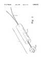
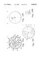
- FIG. 1is a perspective view of a representative embodiment of the implant of the present invention.
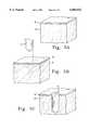
- FIG. 2ais a perspective view of the implant body of the implant depicted in FIG. 1 which further depicts the width (w) and length (l) of the implant body as they relate to the x and the y axis, respectively.
- FIG. 2bshows a top view of the implant body depicted in FIG. 2a which shows the direction of swelling.
- FIG. 2cis a cross-section of the implant depicted in FIG. 1 after placement in a hard tissue, which shows the direction of swelling.
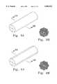
- FIG. 3ais a perspective view of a representative embodiment of the implant body of the present invention.
- FIG. 3bis a cross-section of the implant body of FIG. 3a.
- FIG. 4ais a perspective view of another representative embodiment of the implant body of the present invention.
- FIG. 4bis a cross-section of the implant body of FIG. 4a.
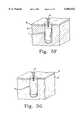
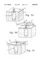
- FIGS. 5a-gare perspective views of the employment of the implant depicted in FIG. 1 as follows:
- FIG. 5adepicts a hard tissue
- FIG. 5bdepicts the hard tissue in relation to an awl to be used to form a cavity in the hard tissue.
- FIG. 5cdepicts the hard tissue after formation of a cavity.
- FIG. 5ddepicts the implant being inserted into the hard tissue via an insertion device.
- FIG. 5edepicts the implant during insertion into the hard tissue.
- FIG. 5fis a perspective view of the implant immediately after insertion.
- FIG. 5gis a perspective view of the implant after swelling.
- FIGS. 6a-care perspective views of the employment of the implant depicted in FIG. 1 for use in attaching a second tissue to a first tissue as follows:
- FIG. 6adepicts the implant after insertion into a hard (first) tissue and swelling.
- FIG. 6bdepicts the implant in relation to a soft (second) tissue to be attached to the hard tissue.
- FIG. 6cdepicts the attachment of the second tissue to the first tissue via a suture.
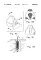
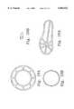
- FIG. 7ais a perspective view of a representative embodiment of a load-distributing device.
- FIG. 7bis a cross-section of the load-distributing device depicted in 7a.
- FIG. 7cis a perspective view of another representative embodiment of a load-distributing device.
- FIG. 7dis a cross-section of the load-distributing device depicted in 7c.
- FIG. 7eis a perspective view of still another representative embodiment of a load-distributing device.
- FIG. 7fis a cross-section of the load-distributing device depicted in 7e.
- FIG. 8ais a perspective view of a representative embodiment of a load-distributing device having a complex shape.
- FIG. 8bis a cross-section of the load-distributing device depicted in 8a.
- FIG. 8cis a side view of the load-distributing device depicted in 8a.
- FIG. 8dis a cross-section of a representative embodiment of the implant which utilizes the load-distributing device depicted in FIGS. 8a-c.
- FIG. 9ais a graphical representation of a series of two of the implants of the present invention being used to secure a first hard tissue to a second hard tissue.
- FIG. 9bis another graphical representation of a series of two of the implants made according to the present invention which are being used to secure a first hard tissue to a second hard tissue.
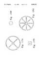
- FIG. 10ais a graphical representation of two surgical screws deployed within a hard tissue.
- FIG. 10bis the same graphical representation showing the use of a representative embodiment of the implant of the present invention as a platform for the surgical screws.
- FIG. 11ais a graphical representation of a hand bone depicting an artificial joint and a bone defect.
- FIG. 11bis the same graphical representation showing the use of a representative embodiment of the implant of the present invention as a platform for the artificial joint.
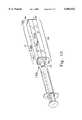
- FIG. 12is a perspective view of a representative embodiment of an apparatus (i.e. a polymer body shaping device), before assembly, which is used to make a polymer body according to the present invention.
- FIG. 12also depicts a standard syringe for which the apparatus is adapted to extrude a polymer material into the mold through the mold die.
- FIG. 13is a perspective view of the apparatus (and syringe) depicted in FIG. 12 after assembly.
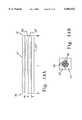
- FIG. 14ais a perspective cross-section view of the mold of FIG. 13 without the polymer mixture/matrix therein.
- FIG. 14bis a cross-section view of the same mold showing the polymer mixture/matrix in the cavity defined by the mold.
- FIGS. 15a-hdepict the various steps which are employed for formation of a polymer body using the apparatus depicted in FIG. 1.
- FIG. 15ais a cross-section of the apparatus (and a side view of the syringe containing the polymer material) before extrusion of the polymer material through the mold die into the mold.
- FIG. 15bis the same view after extrusion of a portion of the polymer material through the mold die into the mold.
- FIG. 15cis the same view after all of the polymer material is extruded through the mold die into the mold.
- FIG. 15dis the same view after disassembly of the mold from around the polymer matrix.
- FIG. 15eis a cross-section of a drying oven containing the polymer matrix vertically suspended therein.
- FIG. 15fis the same view after the polymer matrix has been dried to form a swellable polymer body.
- FIG. 15gis the same view after separation of the polymer body.
- FIG. 15his the same view during cutting of the polymer body to the desired length.
- FIGS. 16a-ddepict a cross-section of the relationship between the shape and appearance of a polymer body and the corresponding shape and appearance of the mold die through which the polymer material is extruded during formation of the polymer body.
- FIG. 16ais a cross-section of the mold die.
- FIG. 16bshows the appearance of the undried polymer body under normal fluorescent light.
- FIG. 16cshows the appearance of the same undried polymer body under polarized light.
- FIG. 16dshows the polymer body after drying.
- FIGS. 17a, 17b, 18a, 18b 19a, 19b, 20a, 20b, 21a and 21bdepict cross-sections of various alternate embodiments of mold dies (FIGS. 17a, 18a, 19a, 20a and 21a) and the corresponding dried polymer bodies (FIGS. 17b, 18b, 19b, 20b and 21b, respectively.)
- the present inventionrelates to uniformly shaped, swellable devices made from polymeric materials.
- the uniformly shaped devicesare adapted for use as implants in tissue repair. More specifically, the implants impart enhanced load bearing capacity to hard tissue, which increases the load that can be put on the hard tissue during the repair process.
- the implants of the present inventionmay be useful for securing or joining a second (hard or soft) tissue to a first (hard) tissue. Additionally, the implants may be useful in anchoring a surgical device, such as a screw or pin, into a hard tissue.
- the implant of the present inventioncomprises a dehydrated, resorbable, swellable preformed body of a crosslinked matrix material.
- One feature of the implant bodyis that it becomes anchored in place after insertion due to swelling upon rehydration, rather than by means of mechanical anchoring, such as protruding barbs and fins. This swelling fills the site of insertion in the hard tissue, which can compensate for any irregularities in the shape of the cavity.
- Another feature of the implant bodyis that it is eventually resorbed. In general, by the time the implant body has completely resorbed, the site that the implant body occupied will have been replaced by native tissue. Because the implant body is eventually resorbed by the body and replaced by native tissue, a second surgery to remove the device is not necessary. Also, in the event of a recurrent injury, the same site may be used to implant another device.
- the implantmay also optionally incorporate other devices, such as load-distributing devices, surgical screws, pins, etc.
- the term “implant”refers to the entire device to be inserted into the hard tissue
- the term “implant body”refers to the portion of the implant consisting of the preformed crosslinked matrix. See, for example, FIG. 1, which depicts a preferred embodiment of the implant (1), and shows the relationship between the implant body (2), and an optional load-distributing device (3) which is used to distribute the load put upon the implant body (2) when the suture (4) is pulled.
- the devices which are made in accordance with the present inventionare formed by extruding a matrix material through a mold die into a mold to produce a preformed "polymer matrix,” which is subsequently dehydrated to form a polymer body.
- the matrix(and thus the polymer body) may also include optional components, such as biologically active agents.
- matrix materialThe choice of matrix material will necessarily depend on the application for which the device will be used. For example, in order to prepare an implant body for in vivo applications, it is first necessary to provide a biocompatible polymer which serves as the matrix material. Depending on the matrix material selected, it may also be necessary to provide a chemical crosslinking agent.
- collagenserves as the matrix material.
- Collagenis the major protein component of bone, cartilage, skin, and connective tissue in animals.
- Collagen in its native formis typically a rigid, rod-shaped molecule approximately 300 nanometers (nm) long and 1.5 nm in diameter. It is comprised of three collagen polypeptides which form a tight triple helix.
- the collagen polypeptidesare characterized by a long midsection having the repeating sequence -Gly-X-Y-, where X and Y are often proline or hydroxyproline, bounded at each end by the "telopeptide" regions, which constitute less than about 5 percent (%) of the molecule.
- the telopeptide region of the collagen chainsare typically responsible for the crosslinking between chains and for the immunogenicity of the protein.
- collagen from any sourcemay be used in the practice of the present invention.
- collagenmay be extracted and purified from human or other mammalian source, such as bovine or porcine corium and human placenta, or may be recombinantly or otherwise produced.
- the preparation of purified collagen in solution from bovine skinis basically a three-step process involving solubilization, enzyme treatment, and purification, as described in U.S. Pat. Nos. 4,140,537 and 4,488,911.
- U.S. Pat. No. 5,428,022discloses methods of extracting and purifying collagen from the human placenta.
- PCT Publication No. WO 94/16570discloses methods of producing recombinant human collagen in the milk of transgenic animals, including transgenic cows.
- Collagen of any typeincluding, but not limited to, types I, II, III, IV, or any combination thereof, may be used, although type I is generally preferred. Either atelopeptide or telopeptide-containing collagen may be used. However, when collagen from a xenogenic source, such as bovine collagen, is used, atelopeptide collagen is generally preferred, because of its reduced immunogenicity compared to telopeptide-containing collagen.
- collagenor “collagen material” as used herein refers to all forms of collagen, including those which have been processed or otherwise modified.
- Collagen for use in the present inventionis typically available in an aqueous suspension (fibrillar collagen) or solution (nonfibrillar collagen) having a collagen concentration within the range of about 10 mg/ml to about 120 mg/ml, preferably, between about 20 mg/ml to about 90 mg/ml.
- Collagen in fibrillar formis preferably used in the practice of the present invention because of its expected superior strength and greater persistence in hard tissue compared to nonfibrillar collagen.
- nonfibrillar collagenmay be used in place of or in addition to fibrillar collagen.
- nonfibrillar collagenas used herein is intended to encompass collagen types that are nonfibrillar in native form (such as types IV, VI, and VII); collagen that has been rendered substantially nonfibrillar by the addition of one or more fiber disassembly agent; and collagen which has been chemically modified such that it is in substantially nonfibrillar form at or around neutral pH.
- Fibrillar collagenmay be rendered nonfibrillar by the addition of one or more fiber disassembly agents.
- the fiber disassembly agentshould be present in an amount sufficient to render the collagen substantially nonfibrillar at pH 7.
- Agents capable of rendering collagen nonfibrillarinclude, without limitation, various biocompatible alcohols, amino acids, inorganic salts, and carbohydrates.
- Collagens that have been chemically modified to be nonfibrillar at neutral pHinclude succinylated collagen and methylated collagen, both of which can be prepared according to the methods described in U.S. Pat. No. 4,164,559.
- polymers which are suitable for use in forming uniformly shaped swellable devicesinclude a wide range of synthetic and naturally occurring materials. In general, the polymers need only be capable of forming a polymer body which is both swellable, and sufficiently strong to withstand the mechanical load to which it is subjected after placement.
- polymer materials which are biodegradable and are suitable for use in forming implant bodies for tissue repairinclude, inter alia, polyesters, polyamides, polypeptides, poly(orthoesters), polyanhydrides, polysaccharides and proteins.
- Suitable polymerscan be hydrophilic or hydrophobic.
- the matrixmay be formed from a single biocompatible polymer, or a mixture of two or more biocompatible polymers.
- a synthetic hydrophilic polymercan be added to a suspension or solution of collagen to enhance the rate of hydration after implantation.
- the matrixmay be formed from a polymer per se, or it may be formed from individual monomeric units which are at least partially polymerized before extrusion through the mold die as described below.
- Crosslinkingmay be achieved by a variety of known chemical and non-chemical methods. Non-chemical methods include, inter alia, irradiation, drying, heating and compression. Preferably, crosslinking is achieved using chemical methods, which includes either ionic or covalent crosslinking. Covalent crosslinking can be achieved by functionalizing the matrix material, or by supplying a separate chemical crosslinking agent. As used herein, the term "crosslinking agent" refers to a chemical crosslinking agent. Crosslinking may also be achieved by a combination of two or more different mechanisms.
- Suitable chemical crosslinking agents for use in the practice of the inventioninclude, without limitation, glutaraldehyde, functionally activated synthetic hydrophobic or hydrophilic polymers, photoactivatable crosslinking agents, formaldehyde, divinyl sulfone, carbodiimide, epoxide, imidazole, and combinations thereof.
- the optimum ratio of crosslinking agent to matrix materialwill, of course, vary depending on the particular crosslinking agent used and the degree of crosslinking desired.
- Aldehyde-containing crosslinking agentssuch as glutaraldehyde and formaldehyde are particularly preferred for use in formation of implant bodies for tissue repair, because the matrices thus formed have sufficient physical strength to withstand the various processing and handling steps (e.g., molding and drying). Also, once dried, a formaldehyde or glutaraldehyde crosslinked collagen matrix has sufficient strength to enhance the structural integrity of hard tissue. Methods for crosslinking collagen using glutaraldehyde are disclosed in U.S. Pat. Nos. 4,582,640 and 4,642,117. When aldehyde-containing crosslinking agents, such as glutaraldehyde or formaldehyde, are used in the practice of the invention, the amount of crosslinking agent is optimized to limit unbound crosslinker in the final product.
- Functionally activated synthetic hydrophilic polymerscan also be used as the crosslinking agent either alone or in combination with the aforementioned crosslinking agents.
- Methods for crosslinking matrix materials using functionally activated synthetic hydrophilic polymersare disclosed in U.S. Pat. Nos. 5,162,430 and 5,328,955.
- Multifunctionally activated synthetic polymersare disclosed in U.S. Pat. No. 5,328,955, which describes the use of difunctionally activated poly(ethyleneglycol)-bis-(succinimidyl glutarate) (SG-PEG) and difunctionally activated poly(ethyleneglycol)-bis-succinimidyl proprionic acid (SE-PEG).
- Optional componentscan be incorporated into the devices at any stage during formation.
- optional componentscan be added to either the polymer or the crosslinker before they are mixed together.
- theycan be added to the reaction mixture at any stage during crosslinking.
- optional componentscan be added to the matrix after crosslinking at any stage of implant processing.
- Particulate materialsmay also be incorporated into the device by incorporating them into the matrix material prior to crosslinking (or the matrix material-crosslinking agent mixture).
- the presence of a particulate material in the implant bodymay serve several functions, as follows: (i) it may aid in shape retention during dehydration of the implant; (ii) it may provide additional roughness to the surface of the implant body to aid in initial fixation of the implant into the hard tissue; and (iii) it may enhance resorbability of the implant by native tissue.
- Particulate materialmay be any shape, such as spherical, elongated fibers, etc.
- fiber-shaped particlescan be included in the reaction mixture and, because of their shape, they would be expected to be oriented in much the same way as the polymer material during extrusion.
- Particulate materials for use in formation of implant bodieshave a preferred particle diameter between about 50 to about 500 ⁇ m; more preferably, between about 75 to about 300 ⁇ m; most preferably, between about 100 to about 200 ⁇ m.
- Particulate materialsare generally incorporated into the biocompatible polymer suspension at a concentration of about 50% wt./wt. or less particulate material/biocompatible polymer ratio. Higher concentrations of particulate material are not preferred, because such compositions will not generally shrink or swell to a sufficient degree to achieve the desired density and associated mechanical strength.
- Suitable particulate materials for use in forming implant bodiesinclude, without limitation, implant-grade biologically-derived polymers such as collagen; synthetic polymers such as poly(lactic acid), poly(glycolic acid), polytetrafluoroethylene; silicon carbide or silicone rubber; hydrogels; and ceramics or glasses such as calcium carbonate, calcium sulfate or other calcium salts.
- implant-grade biologically-derived polymerssuch as collagen
- synthetic polymerssuch as poly(lactic acid), poly(glycolic acid), polytetrafluoroethylene
- silicon carbide or silicone rubbersuch as silicone oils
- hydrogelssuch as calcium carbonate, calcium sulfate or other calcium salts.
- ceramics or glassessuch as calcium carbonate, calcium sulfate or other calcium salts.
- particulate materialsalso refers to mixtures or copolymers containing two or more different types of particulate material, such as those listed above.
- Preferred ceramic particles for use in forming implant bodiesinclude calcium phosphate ceramics, such as tricalcium phosphate particles, hydroxyapatite particles, and mixtures thereof.
- the ceramic particlesgenerally comprise spherical particles having a diameter within the range of about 100 microns to about 1000 microns.
- Biologically active agentsmay also be incorporated into an implant body.
- biologically active agentrefers to molecules which exert biological effects in vivo. Examples of biologically active agents include, without limitation, enzymes, receptor antagonists or agonists, hormones, growth factors, fluoride, antibiotics, antimicrobial agents, and antibodies.
- biologically active agentis also intended to encompass combinations or mixtures of two or more active agents, as defined above. The biologically active agents must also be capable of maintaining their activity in the final implant device.
- Suitable biologically active agents for use in implant bodiesinclude members of the transforming growth factor (TGF) supergene family, which are multifunctional regulatory proteins.
- TGFtransforming growth factor
- Members of the TGF supergene familyinclude the beta transforming growth factors (for example, TGF-1, TGF-2, TGF-3); bone morphogenetic proteins (for example, BMP-1, BMP-2, BMP-3, BMP4, BMP-5, BMP-6, BMP-7, BMP-8, BMP-9); heparin binding growth factors (for example, fibroblast growth factor (FGF), epidermal growth factor (EGF), platelet-derived growth factor (PDGF), insulin-like growth factor (IGF)); Inhibins (for example, Inhibin A, Inhibin B); growth differentiating factors (for example, GDF-1); and Activins (for example, Activin A, Activin B, Activin AB).
- beta transforming growth factorsfor example, TGF-1, TGF-2, TGF-3
- agents which enhance the visualization of the implanted device using various imaging techniquesinclude, inter alia, radiopaque agents, fluorine-containing chemicals, dyes, fluorescent substances and magnetically responsive compounds.
- components which may be incorporated into the matrixinclude, without limitation, the following: polyethylene glycol (non activated), dextrose, glycerol, and glycosaminoglycans such as sodium hyaluronate, chondroitin sulfate and heparin.
- an aqueous suspension/solution of the matrix materialis mixed with a chemical crosslinking agent to form a reaction mixture.
- the matrix materialis preferably present in the aqueous suspension/solution at a concentration within the range of about 10 to about 120 milligrams per milliliter of suspension/solution, preferably, between about 30 to about 90 milligrams per milliliter of suspension/solution.
- the concentration of crosslinking agent usedwill depend upon a number of factors, including the particular crosslinking agent used, the concentration and type of matrix material used, and the degree of crosslinking desired.
- the concentration of glutaraldehydeis generally within the range of about 8 to about 40 micrograms of glutaraldehyde per milligram of matrix material (e.g., when a collagen suspension/solution having a collagen concentration of 35 mg/ml is used, the concentration of glutaraldehyde used to crosslink the collagen would be in the range of about 280 micrograms to about 1.4 milligrams per milliliter of collagen suspension/solution; when a collagen suspension/solution having a collagen concentration of 65 mg/ml is used, the concentration of glutaraldehyde would be about 520 micrograms to about 2.6 milligrams per milliliter of collagen suspension/solution).
- the collagen and crosslinking agentare preferably mixed so that the crosslinking agent is homogeneously dispersed with the matrix material suspension/solution.
- the collagen and crosslinking agentmay be mixed, for example, using syringe-to-syringe mixing.
- the amount of mixing and mixing method chosennecessarily depends on the matrix material and crosslinking agent, as well as their relative concentrations, and can easily be determined and optimized by one of skill in the art.
- the reaction mixtureis introduced into a mold, in which the matrix material and crosslinking agent are allowed to crosslink to form a matrix having the shape of the mold.
- the reaction mixturecan be introduced into the mold and then crosslinked using known methods.
- the matrix material and crosslinking agentare incubated within the mold until complete crosslinking is achieved.
- the reaction mixturemay be incubated at elevated temperature (preferably, no greater than 37° C.) to accelerate the crosslinking reaction.
- the incubation timeis a function of reaction mixture component concentrations and temperature, and can be easily optimized.
- the preferred method for introducing the reaction mixture into the moldis via extrusion through a specially designed mold die.
- the resulting matrixis preferably removed from the mold and washed to remove any salts and excess, unreacted crosslinking agent. Washing may be performed, for example, by soaking the preformed matrix in deionized water overnight, preferably at room temperature or under refrigeration at 2-4° C.
- the swellable polymer bodyis formed by drying the matrix, preferably until it has a moisture content of 20% or less by weight (i.e. until it is "dry") and more preferably less than 15%.
- the matrixmay be dried in an oven at 37° C., which generally requires a minimum of 12 hours, preferably 18-24 hours.
- Suitable moisture contentwill necessarily depend on the desired amount of swelling of the polymer body during use, and can easily be determined by preparing polymer bodies with different moisture contents and choosing the appropriate moisture content for the given application.
- Preformed matrices containing particulate materialsgenerally require shorter drying times. To give the polymer body a certain predetermined shape, it may also be possible to further shape the preformed matrix during the drying process.
- the matrixUpon drying, the matrix should exhibit a sufficient amount of shrinkage due to moisture loss during the drying process to allow adequate swelling to occur during rehydration to meet the needs of a given application. For example, if the swellable polymer body is being used as a hard tissue implant body, the amount of shrinkage during drying will be that which permits a sufficient degree of swelling after implantation to anchor the implant in place. Generally, the matrix should shrink to less than 80%, preferably to less than 50%, and most preferably to between 10% to 25% of its original volume. An elongated matrix will generally shrink to between 10% to 50% of its original diameter, and may also shrink to between 80% to 95% of its length. For example, an elongated matrix prior to drying may have a diameter of 11 mm and a length of 100 mm, but will shrink to about 2.8 to 5.5 mm in diameter and about 80 to 95 mm in length upon drying.
- the polymer bodymay be manufactured under aseptic conditions or terminally sterilized following the dehydration step using e-beam or gamma irradiation.
- a preferred polymer body shapeis one which has a width, w (x-axis) and length, l (y-axis) as depicted in FIG. 2a, wherein the length is greater than the width.
- the widthis equivalent to its diameter, such that when the implant (1) is inserted lengthwise into the hard tissue (2) as depicted in FIG. 2c, the majority of the swelling occurs radially (in an outward direction from the y-axis) as depicted in FIGS. 2b and 2c, thus resulting in a general increase in its diameter.
- the polymer bodymay also have any oblong or irregular shape which is generally elongated (i.e. the greatest dimension of the polymer body along the y axis (i.e. its length) is greater than the greatest dimension in a plane perpendicular to the y axis (i.e. its width)).
- the shape of the polymer bodymay be formed using a mold of a particular shape, or it may be formed after molding. Using an appropriate mold, no further sculpting of the implant body may be necessary. However, it is possible and sometimes desirable to use a mold that exceeds the desired finished dimensions of the preformed matrix, in which case the resulting matrix (or polymer body after drying) may be cut or sculpted to the desired size or shape.
- the polymer bodymay be texturized (e.g., dimpled, pitted or ribbed) to give it an enhanced surface morphology.
- the matrixcan be texturized before, during or after drying.
- the outer surface of the implant bodycan be machined in such a manner as to create a texturized surface after drying.
- the term "enhanced surface morphology"refers to a matrix (or an implant body formed therefrom) having an exterior surface that is not smooth. For example, it may be dimpled, pitted, or ribbed, or otherwise textured so as to increase the surface area of the implant body. This may serve to increase the rate of rehydration of the polymer body, which in turn results in an increased swelling rate.
- the enhanced surface morphologymay also increase the friction between the implant body and the hard tissue to aid in anchoring the implant body into the hard tissue.
- the implant bodyhas edges or protrusions extending outward from a generally cylindrical surface, these edges or protrusions may compress upon insertion to provide an interference fit (i.e. a fit which results in enhanced fixation due to the force of the outer surface of the implant body upon the inner surface of the cavity).
- FIG. 3adepicts a perspective view
- 3bdepicts a cross-section of an implant body having 8 edges extending radially outward from the cylindrical surface of the implant body and running the entire length of the implant.
- the cross-section of the implant bodyis generally octagonal in shape, and the edges result from the intersections of the sides of the octagon.
- a central corewhich extends longitudinally through the implant through which a suture can be threaded.
- FIG. 4aA perspective view of an alternative embodiment is depicted in FIG. 4a. As shown in the cross-section depicted in FIG. 4b, this implant body has protrusions in the form of ribs which run the entire length of the implant body.
- the end of the implant to be insertedmay be tapered (e.g., pointed or bullet-shaped) to facilitate driving the implant into the insertion site.
- the polymer bodies which are made according to the present inventionare used to repair a rotater cuff.
- the dimensions of the implant bodyare preferably between about 1.0 to about 6.0 mm in diameter and between about 3 to about 30 mm in length; more preferably, between about 2.0 to about 5.0 mm in diameter and between about 5 to about 20 mm in length; most preferably, between about to about 2.5 to about 4.5 mm in diameter and between about 8 to about 18 mm in length.
- the polymer bodywill necessarily have different dimensions that would be determined on the basis of their intended purpose.
- the implant bodycan be used alone in the practice of the present invention, or it can be used in conjunction with a load-distributing device, or other surgical devices such as screws, pins, etc. These additional devices can be incorporated into the implant body at any time before or after its formation.
- a surgical pincan be placed within the mold, in which case the preformed matrix and resultant implant body would be formed with the pin already in place.
- the load-distributing or surgical devicecan be attached or inserted into the implant body after formation, but before insertion of the implant into the hard tissue.
- the implantcomprises an implant body and a load-distributing device.
- load-distributing devicerefers to a member which acts to distribute the mechanical forces placed on the implant body when the implant is being used to facilitate attachment of a first tissue to a second tissue. Such load-distributing devices may also be useful in other non-medical applications.
- FIGS. 5a to 5gA general method for insertion is depicted in FIGS. 5a to 5g.
- FIG. 5ashows the hard tissue (5) having a surface (6) into which the implant will be inserted.
- the cavityis generally formed using a surgical drill or awl (7).
- FIG. 5cshows the cavity (8) thus formed.
- the implant (1)is then inserted manually into the cavity as depicted in FIGS. 5d and 5e using manual or mechanically induced pressure.
- Insertion of the implantmay be facilitated by use of a specially designed insertion tool (9) and/or a mallet to drive the implant into the cavity.
- FIG. 5fshows the implant after insertion which is slightly below the surface (6) of the hard tissue (5).
- FIG. 5eshows the implant after the swelling of the implant body as depicted by an increase in diameter, but no substantial increase in length.
- the diameter of the cavity (8)will approximate the diameter of the implant (1) to be inserted.
- a cavitycan be formed which is slightly smaller in diameter than the implant, which allows the implant to be press fit into the cavity.
- the inner diameter of the cavityshould be approximately 0.1-0.5 millimeter less than the outer diameter of the implant, depending on the type and quality of the hard tissue. For example, when an implant having an outer diameter of 3.6 mm is used, the inner diameter of the cavity should be between about 3.1 to about 3.5 mm.
- the implantis generally cylindrical in shape and has protrusions extending outward as depicted in FIGS. 3a-b and 4a-b
- a cylindrical cavityis formed which has a diameter which approximates the smallest diameter of the insert. This diameter differential enhances the interference fit of the implant.
- the implant bodyshould be dense enough to achieve the desired mechanical strength.
- denseit is meant that the implant body is substantially compact, thus restricting its permeability to cells.
- the implants of the present inventionare different from the implants described in U.S. Pat. No. 5,110,604, which are not dense, but are porous. This means that the implant body will restrict tissue ingrowth until the implant body begins to degrade, after which it is capable of being infiltrated by tissue cells and replaced by tissue. In this way, strength can be optimized while still allowing for eventual resorption.
- the load bearing implants of the present inventionare particularly useful in porous bone, where a normal implant may not transfer load effectively to the bone.
- the entire implantswells, which means that the implant can accommodate larger imperfections of poorer quality bone.
- the implant after insertion and rehydration in situpreferably achieves a degree of fixation (i.e. attainment of holding strength) soon enough to allow a surgeon to place a load on the implant during surgery without concern about dislodging the implant. In the ideal case, fixation occurs soon after placement of the device.
- Types of surgical repairsthat can be effected using the implants and methods of the present invention include, without limitation, repairs of the shoulder, endoscopic face lifts, collateral knee ligaments, cruciate knee ligaments, Achilles tendon, patellar tendon, hand, or wrist.
- the implantis used as a suture anchor to attach a second tissue to the hard tissue into which the implant is anchored.
- the implantpreferably has a hollow channel running through its length through which surgical suture can be threaded.
- the mold used to form the implant bodymay contain at least one mandrel running the entire length of the mold. Alternatively, if the mold does not contain a mandrel, a hollow channel can subsequently be formed in the matrix or implant body formed therefrom by drilling or machining the channel after formation.
- At least one standard surgical suture(e.g., Dacron #1 or #2 or braided polyester) is preferably threaded through at least one hollow channel in the implant (or in the matrix prior to drying).
- one suturemay be threaded through one channel; or several sutures may be threaded through the same channel; or several sutures may be threaded, one each, through several channels.
- the suturemay be knotted at the bottom of the implant.
- the implantmay have attached thereto or associated therewith a load-distributing device, which may serve several functions: 1) it may distribute the mechanical forces on the implant; 2) it may prevent the suture from tearing or cutting through the implant; 3) it may aid fixation of the implant into the hard tissue; and 4) it may facilitate "suture slippage," i.e. allowing one end of the suture to slide relative to the other end during surgical procedures, which in turn facilitates complicated manipulations of sutures by surgeons, such as tying knots, especially through an arthroscopic portal (i.e., the knot is tied in an accessible region and slid downward to anchor the tissue).
- a load-distributing devicewhich may serve several functions: 1) it may distribute the mechanical forces on the implant; 2) it may prevent the suture from tearing or cutting through the implant; 3) it may aid fixation of the implant into the hard tissue; and 4) it may facilitate "suture slippage," i.e. allowing one end of the
- the load-distributing device and the implant bodypreferably come in contact over a fairly large area.
- the necessary load bearing capacity of a suture anchor immediately after placementis determined by the forces required to tie the second tissue to the first tissue.
- the implantmust be capable of withstanding the forces necessary to bring the two tissues into close proximity. Since the implant will ultimately be exposed to the same types of forces as are exerted on the suture, the implant should be able to withstand (not be dislodged or damaged) as much forces as the suture for a desired length of time.
- FIGS. 6a to 6cdepict the use of an implant device to attach a soft tissue (10) to a hard tissue.
- the load-distributing device (3)is distal from the surface of the hard tissue (6).
- the suture (4)is threaded around (not shown) the load-distributing device, and is threaded through a hollow channel in the implant body (2).
- the sutureis then threaded through the soft tissue (10).
- the suture slippageallows the soft tissue to be properly moved in place next to the hard tissue. Then, as depicted in FIG.
- FIGS. 7a, c and eshow perspective views of three different load-distributing device designs.
- FIGS. 7b, d and fshow cross-sections of the same devices, respectively.
- the load-distributing devicemay have a modified button-shape with two channels running through the device. The two "sides" of the button can be thought of as the two "ends" of the device. The two channels exit a single hole on one end of the device, and separate holes on the other end.
- This load-distributing deviceis also depicted in FIG. 2c. As shown, the end of the device with the single hole is next to the end of the insert body which is distal from the surface of the hard tissue This configuration is believed to facilitate load distribution.
- FIGS. 7c and 7dshow another embodiment of the load distributing device which is button-shaped.
- the load-distributing devicehas a hollow channel with a center bridging feature around which the suture is threaded. This configuration facilitates suture slippage.
- FIGS. 7e and 7fshows yet another configuration of the load distributing device which consists of two separate members: a disc (12), and a mandrel attached thereto (13), where the mandrel has an eye (14) running through it at the end distal from the disc through which a suture can be threaded.
- a preferred embodiment of the load-distributing devicehas a complex generally conical shape as depicted in FIGS. 8a to 8d.
- the end of the device having the smaller cone diameterwill be distal from the implant body, and the end of the device having the larger cone diameter will be next to the implant body.
- the devicehas a center portion (15) which has a tear-drop shape. The suture is threaded around this center portion, and exits through a single opening (16).
- the devicepreferably has a continuous outer lip (17) in contact with the outer circumference of the implant body.
- the load-distributing devicemay be manufactured from any medical grade ceramic (e.g., alumina, zirconia, hydroxyapatite), polymer (e.g., polysulfone, polymethyl methacrylate, ultra-high molecular weight polyethylene), metal (e.g., stainless steel or titanium), or composite material, but is preferably made from a material that is at least partially biodegradable, more preferably, fully biodegradable, such as a highly crosslinked collagen material.
- ceramice.g., alumina, zirconia, hydroxyapatite
- polymere.g., polysulfone, polymethyl methacrylate, ultra-high molecular weight polyethylene
- metale.g., stainless steel or titanium
- composite materialbut is preferably made from a material that is at least partially biodegradable, more preferably, fully biodegradable, such as a highly crosslinked collagen material.
- the implant bodymay also be used alone as an implant (i.e. inserted by itself without a load-distributing device or other surgical device attached thereto or associated therewith.)
- the implant of the present inventionmay be used to secure two hard tissues together as depicted in FIGS. 9a and 9b and further described in Example 7. As shown, a series of two implants (18' and 18") can be inserted into a damaged bone to prevent further damage during healing.
- the implant bodymay be used alone to join cartilagenous tissues together, such as in the repair of articular cartilage or the meniscus.
- the implant of the present inventionmay also be used to enhance the mechanical integrity and thus the load bearing capacity of a hard tissue by serving as a platform for attachment of a surgical device such as a screw, rod or pin. See FIGS. 10a and b, and 11a and b and refer to Example 8 for a further explanation.
- a surgical devicesuch as a screw, rod or pin.
- surgical screws (19' and 19")are commonly used in bone repair.
- FIG. 10bshows the use of a series of implants (20' and 20") which are used to facilitate fixation of the screws.
- FIG. 11ashows the use of an artificial joint (21), one end of which is inserted into a bone with a boney defect (22).
- an implant (23)can be used to enhance the structural integrity of the bone at the location of the boney defect.
- the implantmay contain a cavity which is adapted to receive the surgical device.
- the cavitycan be formed either by using an appropriately shaped mold to form the implant body, or the implant body can be sculpted after formation.
- the polymer matrixis shaped by extruding the reaction mixture containing the matrix material and any other optionally included components through a specially designed "mold die.”
- the mold diefunctions by changing the cross-sectional orientation of the polymeric material during the extrusion process, which provides for different shrinkage characteristics across the cross-section of the matrix during drying. Accordingly, in order to retain this change in orientation throughout the entire length of the mold, the reaction mixture should be sufficiently viscous prior to extrusion to maintain its shape during and after extrusion. This generally necessitates that the reaction mixture is somewhat gelatinous, i.e. it has some of the physical properties of a quasi-solid.
- FIG. 12A representative embodiment of an apparatus (24) according to the present invention is shown in FIG. 12. Also depicted in FIG. 12 is a standard syringe which can be used to load the reaction mixture into the mold.
- the apparatusexcluding the syringe, is also referred to herein as a "polymer body shaping device" or simply a “shaping device.”
- a two-piece syringe adapter (25)can be used along with the shaping device (24), and may also be useful in holding the mold die (26) in place next to the two-piece mold (27).
- a second mold die (26')can be used to hold a mandrel (28) in place.
- the mandrelis used to form a polymer body with a channel running through its length as described above and depicted in FIG. 1.
- the inner walls (29' and 29") of the two pieces of the mold (27' and 27")join together to form one continuous inner surface which defines an elongated cavity into which the polymer mixture is extruded.
- the moldhas a length, "l,” and an inner diameter, "d,” and the cavity extends along the longitudinal axis of the mold between the proximal end (30) and distal end (31) of the mold. Then, as shown in FIG. 14b after extrusion of the polymer mixture into the mold, the polymer mixture fills the cavity and surrounds the mandrel (28).
- the molddefines an elongated cylindrically-shaped cavity and has a length and inner diameter which are sufficient to produce a polymer body with the desired length and width, respectively.
- the length of the moldis between about 75 mm and about 300 mm, more preferably about 150 mm, and the diameter of the cavity is preferably between about 9 and about 14.5 mm.
- FIGS. 15a-hshow how the shaping device depicted in FIGS. 12 and 13 can be used to form uniformly shaped polymer bodies of different lengths.
- FIG. 15ashows a cross-section of the shaping device (and a side view of the syringe containing the reaction mixture) before extrusion through the mold die (26) into the mold (27).
- FIG. 15bshows the same view after partial extrusion of the reaction mixture into the mold (27).
- FIG. 15cshows the shaping device after extrusion has been completed and the syringe and syringe adapter (25) have been disconnected from the shaping device (24).
- FIG. 15dshows the same shaping device after the two-piece mold has been disassembled to expose the polymer matrix (32).
- FIGS. 15e and fshow the polymer matrix in a drying oven before (15e) and after (15f) drying the polymer matrix.
- the polymer matrixis hung vertically in the drying oven, and allowed to dry at a sufficient temperature and a sufficient length of time to drive water from the matrix without harming the biocompatible polymer.
- this temperatureis generally between 22° C. and 35° C., and for polymer matrix having a diameter of 14.4 mm, a drying time of 18-36 hours is preferred to achieve a final moisture content of 2-3% and a final diameter of about 3.5 mm.
- FIG. 15gshows removal of the mold dies (26 and 26') and the mandrel (28) from the uniformly shaped polymer body (33).
- FIG. 15hshows the polymer body containing a central cavity (34) and a diameter, "d,” being cut into desired lengths, "l.”
- FIGS. 16a-ddepict a cross-section of the relationship between the shape and appearance of a polymer body and the corresponding shape and appearance of the mold die through which the polymer material is extruded during formation of the polymer body. This relationship dictates the drying characteristics of the polymer matrix, which in turn dictates both the shape and rehydration characteristics of the polymer body.
- a cross-section of a preferred embodiment of a mold dieis shown in FIG. 16a.
- the preferred mold die designis that of a "spiderwheel” having a plurality of angularly spaced ribs (35) which fan out radially from the axis of the spiderwheel (36) and form a plurality of apertures (37) shaped like "pieces of a pie” in the mold die through which the polymer material can be extruded. Also shown is a central core in the mold die which runs along the axis (36), and which could be occupied by a mandrel as described above and shown in FIGS. 15a-f. It is hypothesized that during extrusion, the polymer molecules come in contact with the inner surfaces (38) of these apertures (37) and become oriented in a direction which is parallel to the direction of extrusion, i.e. along the length of the mold.
- FIG. 16bshows the appearance of the polymer matrix (i.e. the undried polymer body) under normal fluorescent light after it has been extruded through the mold die into the mold.
- the areas corresponding to the location of the ribsappear darker.
- the polymer matrixis extruded through eight different apertures which effectively splits the polymer matrix into eight separate streams as it passes through the mold die, the polymer matrix is sufficiently gelatinous for these separate streams to rejoin into one continuous matrix after extrusion.
- the pattern of reflected lightwhich is shown in FIG. 16b would be expected to be consistent throughout the length of the mold die.
- the length of the mold diecan be shortened, the viscosity of the polymer matrix can be increased, or the flow rate of extrusion can be slowed, or a combination of these can be employed, to ensure uniformity of the shape and physical properties of the dried polymer body.
- FIG. 16cshows the appearance of the polymer matrix under polarized light. Again, it can be seen that the areas corresponding to the location of the ribs have a different appearance that the areas in-between the ribs which suggests that the polymer molecules in these areas may be oriented differently.
- FIG. 16cshows the dried polymer body which, as shown, has shrunk in diameter to about one fifth its size when wet (FIGS. 16b and c), while the diameter of the central core (39) has remained the same.
- FIG. 16dis the pattern of shrinkage of the polymer body using this type of mold die. As shown, shrinkage is greater in-between the areas where the polymer came into contact with the ribs of the mold die, resulting in a "star shaped" polymer body.
- the mold diecan have any shape, size and design which is necessary to achieve the desired size and swellability, and can be easily designed according to the principles described above for the spiderwheel design.
- the mold diehas an essentially central axis with at least three ribs extending radially outward therefrom which form at least three separate apertures through which the polymer material is extruded. It may also be desirable to use a mold die with two or more axes, ribs which are not straight, apertures which are unequal in size, etc. Examples of different mold dies, each having a distinctive pattern, and the corresponding polymer bodies which are formed by extrusion through these mold dies are shown in FIGS. 17-21.
- a solution of glutaraldehyde(in PBS pH 7.4) was prepared with a final aldehyde concentration of 1550 ppm.
- a 30 cc syringewas filled with 9.3 grams of the glutaraldehyde solution.
- a second 30 cc syringewas filled with 20 grams of fibrillar collagen at 70 mg/ml. (Collagen Corporation, Palo Alto, Calif.).
- the syringe containing the collagen suspensionwas connected to the syringe containing the glutaraldehyde solution using a syringe connector.
- the glutaraldehyde and collagenwere mixed using syringe-to-syringe mixing for 20-40 passes of material between the syringes.
- the collagen/glutaraldehyde reaction mixturewas extruded into two separate cylindrical molds each having a 13 mm outside diameter and a mandrel running through the center, and incubated at 37° C. for one hour to allow complete crosslinking to be achieved between the collagen and the glutaraldehyde.
- the resulting implant bodywas removed from the mold and soaked in deionized water overnight at room temperature.
- the preformed bodywas dried for two days at room temperature, then placed in an oven at 37° C. for about 24 hours to complete the drying process, then terminally sterilized using gamma irradiation.
- a solution of glutaraldehyde in PBS pH 7.4was prepared with a final aldehyde concentration of 1550 ppm.
- a 30 cc syringewas filled with a mixture of 20 ml fibrillar collagen at 70 mg/ml with 1.4 grams tricalcium phosphate (TCP) (50% wt./wt.).
- TCPtricalcium phosphate
- the syringe containing the collagen/TCP mixturewas connected to the syringe containing the glutaraldehyde solution using a syringe connector.
- the glutaraldehyde and collagen/TCP mixturewere mixed using syringe-to-syringe mixing for 20-40 passes of material between the syringes.
- the collagen/TCP/glutaraldehyde reaction mixturewas extruded into two separate cylindrical molds, each having an 11 mm outside diameter and a mandrel running through the center, and incubated at 37° C. for one hour to allow complete crosslinking to be achieved between the collagen and the glutaraldehyde.
- the resulting preformed bodywas removed from the mold and soaked in deionized water overnight at room temperature, then dried in an oven at 37° C. for 18 hours, then terminally sterilized using gamma irradiation.
- PBSphosphate buffered saline
- the implant bodywas removed from the vial, rinsed and blotted to remove excess water. The dimensions of the implant body were measured, then the implant body was returned to the vial for further hydration. The results are given below in Table 1. (It should be noted that expansion during actual use will be limited by the diameter of the hole and the quality of the bone.)
- the mechanical strength of glutaraldehyde-crosslinked collagen bone anchors(collagen bone anchors), prepared as described in Example 1, and glutaraldehyde-crosslinked collagen bone anchors containing ceramic particles (collagen--ceramic bone anchors), prepared as described in Example 2, was measured in SawbonesTM, a polymeric foam bone model (manufactured by Pacific Research Laboratories, Vashon, Wash.). A commercially available bone suture anchor, the Innovasive 3.5TM, was used as a control.
- the bone anchorswere placed in 3.5 mm diameter, 13 mm deep depressions in the Sawbones and allowed to rehydrate in 37° C. PBS until maximum strength was achieved. The anchors were then pulled perpendicular to the Sawbones surface at a rate of 100 millimeters per minute using an Instron Model 4202. Results of pull-out testing are presented in Table 2, below.
- the mechanical strength of glutaraldehyde-crosslinked collagen bone anchors(collagen bone anchors), prepared as described in Example 1, and glutaraldehyde-crosslinked collagen bone anchors containing ceramic particles (collagen--ceramic bone anchors), prepared as described in Example 2, was measured in the greater tuberosity of the humeral head of cadaver bones. This site was chosen as it is the specific site used in rotator cuff repair. A commercially available bone suture anchor, the Innovasive 3.5 ROCTM, was used as a control.
- the bone anchorswere hydrated in situ for at least one hour in physiological solution at 37° C., then pulled perpendicular to the bone surface at a rate of 305 millimeters per minute using an Instron Model 8511.
- stainless steel wirewas used in place of the Dacron #2 suture in order to permit measurement of the ultimate pull-out strength of the anchor.
- the ultimate pull-out strength of the collagen bone anchorswas measured to be 160 ⁇ 47 N.
- the ROCTM anchorsfailed at 119 ⁇ 32 N.
- the ultimate pull-out strength of the collagen bone anchorswas measured to be 170 ⁇ 57 N.
- the implant disclosedmay be used alone or in multiples to reattach avulsed soft tissue to hard tissue, for example, in repair of the rotator cuff of the shoulder.
- a cavityis created in the trough between the humeral head and the greater tuberosity of the humerus.
- the implantwhich includes an implant body, a load-distributing device, and suture (hereinafter referred to as "bone anchor") as depicted in FIG. 1 is introduced into a cavity. This may be accomplished by hand pressure or by using an instrument consisting of a sleeve into which the bone anchor is placed and a plunger which forces the anchor into the cavity.
- the bone anchoris placed into the cavity so that the anchor is countersunk below the surface of the humeral trough with the free ends of the suture protruding out of the cavity.
- the free ends of the sutureare then passed through the avulsed tendon and tied on the superior surface.
- One or more bone anchorsmay be used to repair the rotator cuff, these anchors being spaced a suitable distance apart in the humeral trough.
- the implant bodyis resorbed and replaced by native tissue.
- the load-distributing member and suturemay or may not resorb depending upon the material employed in their construction.
- the cavity created to receive the anchoris filled by native tissue, which may be expected to enhance the soft tissue to hard tissue repair.
- FIG. 1Another example of soft tissue to hard tissue repair is in reattachment of the glenoid labrum of the shoulder to the scapula ("Bankart Repair").
- a cavityis created in the periphery of the glenoid rim of the scapula.
- the implant body, load-distributing device, and suture(hereinafter referred to as "bone anchor") is introduced into the cavity. This may be accomplished by hand pressure or by using an instrument consisting of a sleeve into which the bone anchor is placed and a plunger which forces the anchor into the cavity.
- the bone anchoris placed into the cavity so that the anchor is countersunk below the surface of the glenoid rim with the free ends of the suture protruding out of the cavity.
- the free ends of the sutureare then passed through the avulsed glenoid labrum and tied on the surface away from the scapula.
- One or more bone anchorsmay be used to repair the glenoid labrum, these anchors being spaced a suitable distance apart around the periphery of the glenoid rim.
- the implant bodyis resorbed and replaced by native tissue.
- the load-distributing member and suturemay or may not resorb depending upon the material employed in their construction. In any case, the cavity created to receive the anchor is filled by native tissue, which may be expected to enhance the soft tissue to hard tissue repair.
- FIG. 1Another example of soft tissue to hard tissue repair is in reattachment of the patella tendon (ligamentum patellae) to the tibial tubercle.
- a cavityis created in the tibial tubercle.
- the implant body, load-distributing device, and suture(hereinafter referred to as "bone anchor") is introduced into the cavity. This may be accomplished by hand pressure or by using an instrument consisting of a sleeve into which the bone anchor is placed and a plunger which forces the anchor into the cavity.
- the bone anchoris placed into the cavity so that the anchor is countersunk below the surface of the tibia with the free ends of the suture protruding out of the cavity.
- the free ends of the sutureare then passed through the avulsed patella tendon and tied on the superior surface.
- One or more bone anchorsmay be used to repair the patella tendon, these anchors being spaced a suitable distance apart laterally across the tibia.
- the implant bodyis resorbed and replaced by native tissue.
- the load-distributing member and suturemay or may not resorb depending upon the material employed in their construction. In any case, the cavity created to receive the anchor is filled by native tissue, which may be expected to enhance the soft tissue to hard tissue repair.
- the implantmay be used to attach two hard tissues together by means of mechanical forces alone.
- two implantswere used in each of the applications depicted in FIGS. 9a and 9b, it is possible to use a single implant, or a series of three or more implants.
- a free osteochondral fragmentmay be reattached to the articular surface of the femur using one or more of the implants in a manner similar to a surgical pin (FIG. 9b). The fragment is aligned with the defect in the articular surface and one or more of the implants are driven through the fragment into the subchondral bone.
- the apparatusswells and achieves an interference fit in both the fragment and the underlying bone, maintaining the two in close apposition and facilitating healing of the osteochondral fragment to bone.
- the implantresorbs and is replaced by native tissue, leaving no residual material to interfere the normal remodeling process of bone nor to act as a stress riser that could provide an initiation site for a new fracture.
- any bone chipmay be reattached to the bony site from which it came using the same method described.
- the implantmay be used to join two ends of a fractured small bone together to enable fracture repair.
- the two ends of the bonecan be aligned and one or more of the apparatus driven lengthwise through the intermedullary space. Once in place, the apparatus swells and achieves an interference fit in both fragments of bone, maintaining the two in close apposition and facilitating healing of the two bone fragments.
- the implantresorbs and is replaced by native tissue, leaving no residual material to interfere the normal remodeling process of bone nor act as a stress riser that could provide an initiation site for a new fracture.
- Implant(Implant Body) as a Platform for the Attachment of a Surgical Device
- FIG. 10athe implant facilitates fixation of the screw to the vertebral body by acting as a sleeve between screw and bone, filling the gaps in the bone and providing a more uniform surface for the screw threads to engage.
- the implantprovides improved immediate holding strength of the screw into the vertebrae.
- the apparatusis resorbed and replaced by native tissue which fills the space up to the threads of the screw.
- the implantmay be used in revision synthetic implant surgery to fill gaps in bone caused by osteolysis prior to insertion of a new synthetic implant into the site.
- the implantmay be inserted into the intermedullary canal of the metacarpal after removal of the failed synthetic total finger joint replacement to fill gaps caused by osteolysis (FIG. 11a).
- a new total finger jointmay then be inserted with the stem of the joint being driven into a cavity in the center of the insert as depicted in FIG. 11b.
- the implantprovides a platform for the total finger joint in the bone, enhancing its immediate stability.
- the implantis resorbed and replaced by native tissue which fills up the space up to the surface of the synthetic implant stem.
- the shear strength of glutaraldehyde-crosslinked fibrillar collagen pinswas measured in Sawbones. Pins were placed into 2.6 mm diameter holes in adjoining Sawbones and allowed to rehydrate in 37° PBS for three days. The Sawbones were pulled apart at a rate of 50 mm/minute using an Instron Model 4202. The orientation of the pins in the Sawbones was such that the pins were subjected primarily to shear forces. The strength of the pins was determined to be approximately 6 MPa.
- the CBAswere composed of either dehydrated glutaraldehyde-cross linked fibrillar collagen or dehydrated glutaraldehyde-cross linked fibrillar collagen with tricalcium phosphate, and were prepared as described in Examples 1 and 2, respectively. All CBAs included a load distributing device made of polymethyl methacrylate (PMMA).
- the CBAswere gamma irradiated (2.5 Mrad) or aseptically prepared.
- the patellar tendonwas elevated from its tibial insertion site and repaired by the insertion of two implants into the tibia and then attached with a #2 braided polyester suture using a modified whip stitch.
- the animalswere bandaged in full extension using a modified bulky soft bandage. The bandages were removed after 21 days and animals were sacrificed six weeks post-operatively. The right and left hind limbs were x-rayed, mechanically tested, and histologically processed.
- Bone anchorswhich facilitate reattachment of soft tissue to bone, are currently made from metal, nondegradable plastics, and synthetic bioabsorbable polymers.
- the ideal bone anchorwould provide initial stabilization of soft tissue, be easily deployed arthroscopically, be degraded over time, and be eventually replaced by normal bone.
- Bioabsorbable collagen-based implantshave been used successfully for bone grafting (Cornell C N, et al., J Orthop Trauma 5(1):1-8, 1991) and soft tissue augmentation (Keefe J. et al., Clin Mater 9:155-162, 1992). The objective of this study was to evaluate the biocompatibility and degradation of two collagen bone anchor formulations in a rabbit model.
- the implant devices used in this studywere two-part devices: an implant body and a load-distributing device through which a suture could be threaded. See FIG. 1.
- the implant bodyconsisted of dehydrated glutaraldehyde-crosslinked fibrillar collagen (FC) or glutaraldehyde-crosslinked fibrillar collagen with ⁇ -tricalcium phosphate ceramic particles (FC-TCP).
- FCis highly purified bovine dermal collagen which is >95% Type I and ⁇ 5% Type III collagen.
- the button-shaped washerwas made by yttria-partially stabilized zirconia (YTZP), and the suture was #2 braided polyester.
- YTZPyttria-partially stabilized zirconia
- the dried implant bodyhydrates in situ, swelling and locking the anchor into the predrilled bone hole.
- the washerprovides suture slip capability (for arthroscopic knot tying) and distributes the suture load to the implant body.
- Histological evaluationswere performed by a veterinary pathologist on decalcified sections stained with hematoxylin and eosin. For pullout testing, the condyles were dissected free of all soft tissue and the sutures pulled at 100 mm/minute perpendicular to the bone surface until failure.
- FC-TCP anchorsalso showed mild granulomatous inflammatory activity at later timepoints. Extensive degradation of the FC-TCP anchors was seen at six weeks, although both formulations showed comparable levels of degradation at 12 weeks. Osteoblast-like cells and new bone were observed within the collagen bodies by 12 weeks. Notable chondrogenic activity, mostly over the top of the anchor and down into the suture hole, was observed at 12 weeks for the FC formulation. For both formulations, a well-developed bony "cap” formed over the tops of anchors seated below the cortical bone layer; this cap was less established for anchors which protruded into that layer or above the surface.
- a 30 cc syringewas filled with 9.3 grams of the glutaraldehyde solution.
- a second syringewas filled with a fibrillar collagen suspension to a final concentration of 65 mg/ml.
- the syringe containing the collagen suspensionwas connected to the syringe containing the glutaraldehyde solution using a syringe connector.
- the glutaraldehyde and collagenwere mixed using syringe-to-syringe mixing for 20-40 passes of material between the syringes.
- the collagen/glutaraldehyde reaction mixturewas extruded into a shaping device having a cylindrical cavity and a teflon mandrel running longitudinally through the cavity as shown in FIGS. 15a-d.
- the shaping devicealso comprised a mold die as depicted in FIG. 16a.
- the extruded collagen matrixwas allowed to incubate inside the shaping device for one hour at 37° C. to allow complete crosslinking.
- the resulting preformed collagen matrixwas placed vertically in a drying oven and allowed to air dry under quiescent conditions at 15-25° C. for 18-36 hours.
- the final tubular producthad a water content of 2-3%, with a longitudinal shrinkage in a direction parallel to the central axis of the tube.
- the resulting dried tubular producthad a final diameter of 3.5 mm, with a capability of expanding radially outward up to 14.5 mm upon rehydration.
- Cross-sectional analysis of the collagen matrixrevealed eight lines of different intensity, radiating from the central axis of the matrix.
- the eight lineswere introduced into the gel by the spiderwheel-shaped mold die during extrusion. Since shrinkage rates during drying differed between the area around the extrusion lines and the undisturbed gel, the dried product of an implant body had a shape which, in cross-section, was generally of a star shape with eight points as shown in FIG. 16d.
Landscapes
- Health & Medical Sciences (AREA)
- Chemical & Material Sciences (AREA)
- Life Sciences & Earth Sciences (AREA)
- Engineering & Computer Science (AREA)
- Animal Behavior & Ethology (AREA)
- General Health & Medical Sciences (AREA)
- Public Health (AREA)
- Veterinary Medicine (AREA)
- Epidemiology (AREA)
- Surgery (AREA)
- Materials Engineering (AREA)
- Composite Materials (AREA)
- Heart & Thoracic Surgery (AREA)
- Oral & Maxillofacial Surgery (AREA)
- Transplantation (AREA)
- Mechanical Engineering (AREA)
- Vascular Medicine (AREA)
- Dermatology (AREA)
- Medicinal Chemistry (AREA)
- Inorganic Chemistry (AREA)
- Biophysics (AREA)
- Rheumatology (AREA)
- Nuclear Medicine, Radiotherapy & Molecular Imaging (AREA)
- Biomedical Technology (AREA)
- Medical Informatics (AREA)
- Molecular Biology (AREA)
- Prostheses (AREA)
- Materials For Medical Uses (AREA)
Abstract
Description
TABLE 1 ______________________________________ Hydration Results Time % Weight Gain % Length Gain % Diameter Gain ______________________________________ 1 hr 81 0 17 3 130 1 32 6 149 2 36 24 184 3 40 48 187 3 41 72 179 3 46 ______________________________________
TABLE 2 ______________________________________ Holding Strength Anchor Type Holding Strength (N) ______________________________________ Collagen 162 Collagen - ceramic 159 3.5 ROC ™ 228 ______________________________________
TABLE 3 ______________________________________ Peak Load, N Group Time (wks) (mean ± sd) ______________________________________ Mitek 0 246 ± 19 CBA 0 274 ± 21Mitek 6 1119 ± 12CBA 6 1208 ± 490Control 6 2481 ± 408 ______________________________________
Claims (36)
Priority Applications (2)
| Application Number | Priority Date | Filing Date | Title |
|---|---|---|---|
| US09/004,550US6083522A (en) | 1997-01-09 | 1998-01-08 | Devices for tissue repair and methods for preparation and use thereof |
| US09/362,124US6280474B1 (en) | 1997-01-09 | 1999-07-27 | Devices for tissue repair and methods for preparation and use thereof |
Applications Claiming Priority (3)
| Application Number | Priority Date | Filing Date | Title |
|---|---|---|---|
| US78101297A | 1997-01-09 | 1997-01-09 | |
| US83387497A | 1997-04-10 | 1997-04-10 | |
| US09/004,550US6083522A (en) | 1997-01-09 | 1998-01-08 | Devices for tissue repair and methods for preparation and use thereof |
Related Parent Applications (1)
| Application Number | Title | Priority Date | Filing Date |
|---|---|---|---|
| US83387497AContinuation-In-Part | 1997-01-09 | 1997-04-10 |
Related Child Applications (1)
| Application Number | Title | Priority Date | Filing Date |
|---|---|---|---|
| US09/362,124DivisionUS6280474B1 (en) | 1997-01-09 | 1999-07-27 | Devices for tissue repair and methods for preparation and use thereof |
Publications (1)
| Publication Number | Publication Date |
|---|---|
| US6083522Atrue US6083522A (en) | 2000-07-04 |
Family
ID=27119788
Family Applications (2)
| Application Number | Title | Priority Date | Filing Date |
|---|---|---|---|
| US09/004,550Expired - LifetimeUS6083522A (en) | 1997-01-09 | 1998-01-08 | Devices for tissue repair and methods for preparation and use thereof |
| US09/362,124Expired - LifetimeUS6280474B1 (en) | 1997-01-09 | 1999-07-27 | Devices for tissue repair and methods for preparation and use thereof |
Family Applications After (1)
| Application Number | Title | Priority Date | Filing Date |
|---|---|---|---|
| US09/362,124Expired - LifetimeUS6280474B1 (en) | 1997-01-09 | 1999-07-27 | Devices for tissue repair and methods for preparation and use thereof |
Country Status (3)
| Country | Link |
|---|---|
| US (2) | US6083522A (en) |
| AU (2) | AU6021598A (en) |
| WO (2) | WO1998030141A2 (en) |
Cited By (163)
| Publication number | Priority date | Publication date | Assignee | Title |
|---|---|---|---|---|
| US20020026201A1 (en)* | 1994-09-16 | 2002-02-28 | Foerster Seth A. | Methods for defining and marking tissue |
| US20020058882A1 (en)* | 1998-06-22 | 2002-05-16 | Artemis Medical, Incorporated | Biopsy localization method and device |
| US20020110541A1 (en)* | 1999-06-07 | 2002-08-15 | Wright Medical Technology, Inc. | Bone graft substitute composition |
| US20020151466A1 (en)* | 1992-02-11 | 2002-10-17 | Hubbard William G. | Tissue augmentation material and method |
| US20020169066A1 (en)* | 2001-04-16 | 2002-11-14 | Cerabio, L.L.C. | Dense porous structures for use as bone substitutes |
| US20030008831A1 (en)* | 1998-08-10 | 2003-01-09 | Chunlin Yang | Type III collagen compositions |
| US6521244B1 (en)* | 2000-06-13 | 2003-02-18 | Nozomu Kanesaka | Body filling material |
| US20030141618A1 (en)* | 2001-11-30 | 2003-07-31 | Cambridge Polymer Group, Inc. | Layered aligned polymer structures and methods of making same |
| US20030195565A1 (en)* | 1996-08-19 | 2003-10-16 | Bonutti Peter M. | Tissue fixation device |
| US6652887B1 (en) | 2002-06-24 | 2003-11-25 | Wright Medical Technology, Inc. | Bone graft substitute composition |
| US20030235621A1 (en)* | 2002-06-24 | 2003-12-25 | Miller Leasa C. | Bone graft substitute composition |
| US20040034351A1 (en)* | 2002-08-14 | 2004-02-19 | Sherman Michael C. | Techniques for spinal surgery and attaching constructs to vertebral elements |
| US20040034437A1 (en)* | 2002-08-15 | 2004-02-19 | Reinhold Schmieding | Osteochondral repair using plug fashioned from whole distal femur or condyle formed of hydrogel composition |
| US20040062790A1 (en)* | 2002-09-26 | 2004-04-01 | Constantine Barry E. | Hemostatic compositions and methods |
| US20040185021A1 (en)* | 1992-02-11 | 2004-09-23 | Bioform Inc. | Tissue augmentation material and method |
| US20040220681A1 (en)* | 2003-02-04 | 2004-11-04 | Cole Jantzen A. | Injectable resorbable bone graft material, powder for forming same and methods relating thereto for treating bone defects |
| US20050019488A1 (en)* | 2001-11-30 | 2005-01-27 | Cambridge Polymer Group, Inc., Boston, Ma | Layered aligned polymer structures and methods of making same |
| US20050085919A1 (en)* | 2003-10-17 | 2005-04-21 | Zimmer Technology, Inc. | Method and instruments for positioning humeral component during shoulder arthroplasty |
| US20050142219A1 (en)* | 2003-12-26 | 2005-06-30 | Diversified Natural Products, Inc. | Essentially sodium-free potassium salt derived from seaweed |
| US20050245876A1 (en)* | 2003-12-24 | 2005-11-03 | Accessclosure, Inc. | Apparatus and methods for facilitating access through a puncture including sealing compound therein |
| US6994722B2 (en) | 2001-07-03 | 2006-02-07 | Scimed Life Systems, Inc. | Implant having improved fixation to a body lumen and method for implanting the same |
| US20060088601A1 (en)* | 2004-10-22 | 2006-04-27 | Wright Medical Technology, Inc. | Synthetic bone substitute material |
| US20060100664A1 (en)* | 2004-11-05 | 2006-05-11 | Accessclosure, Inc. | Apparatus and methods for sealing a vascular puncture |
| US20060099238A1 (en)* | 2004-11-05 | 2006-05-11 | Accessclosure, Inc. | Apparatus and methods for sealing a vascular puncture |
| US20060253072A1 (en)* | 2005-04-22 | 2006-11-09 | Accessclosure, Inc. | Apparatus and methods for sealing a puncture in tissue |
| US20060293675A1 (en)* | 2005-06-23 | 2006-12-28 | Zhigang Li | Tissue repair device and fabrication thereof |
| US20060290029A1 (en)* | 2005-06-23 | 2006-12-28 | Zhigang Li | Tissue repair device and fabrication thereof |
| US20060293674A1 (en)* | 2005-06-23 | 2006-12-28 | Zhigang Li | Tissue repair device and fabrication thereof |
| US20070001341A1 (en)* | 2005-06-23 | 2007-01-04 | Zhigang Li | Tissue repair device and fabrication thereof |
| US20070010891A1 (en)* | 2003-07-16 | 2007-01-11 | Waldemar Link Bmbh & Co. Kg | Hip prosthesis provided with a shaft inserted into the femur |
| US7211266B2 (en) | 2002-03-29 | 2007-05-01 | Wright Medical Technology, Inc. | Bone graft substitute composition |
| US20070231366A1 (en)* | 2006-03-29 | 2007-10-04 | Sawhney Amarpreet S | Superabsorbent, freeze dried hydrogels for medical applications |
| US7316704B2 (en) | 2003-06-04 | 2008-01-08 | Accessclosure, Inc. | Occlusion member and tensioner apparatus and methods of their use for sealing a vascular puncture |
| US20080009794A1 (en)* | 2005-04-22 | 2008-01-10 | Accessclosure, Inc. | Apparatus and method for temporary hemostasis |
| US20080082122A1 (en)* | 2006-09-13 | 2008-04-03 | Farhad Khosravi | Apparatus and methods for sealing a vascular puncture |
| US7371409B2 (en) | 2001-09-06 | 2008-05-13 | Wright Medical Technology, Inc. | Bone graft substitute composition |
| US20080255560A1 (en)* | 2004-05-21 | 2008-10-16 | Myers Surgical Solutions, Llc | Fracture Fixation and Site Stabilization System |
| WO2007112024A3 (en)* | 2006-03-24 | 2008-11-06 | Johnson & Johnson Regenerative | Barbed sutures having a therapeutics agent thereon |
| WO2007076376A3 (en)* | 2005-12-19 | 2008-12-04 | Stout Medical Group Lp | Expandable delivery device |
| US20090004239A1 (en)* | 2007-06-27 | 2009-01-01 | Sebastien Ladet | Dural repair material |
| US20090062922A1 (en)* | 2007-09-05 | 2009-03-05 | Mckay William F | Method and apparatus for delivering treatment to a joint |
| US20090060971A1 (en)* | 2007-09-05 | 2009-03-05 | Mckay William F | Methods of treating a trauma or disorder of the knee joint by local administration and sustained-delivery of a biological agent |
| US20090069838A1 (en)* | 2004-12-06 | 2009-03-12 | Paul Ram H | Inflatable occlusion devices, methods, and systems |
| US20090088793A1 (en)* | 2007-09-28 | 2009-04-02 | Accessclosure, Inc. | Apparatus and methods for sealing a vascular puncture |
| US20090254110A1 (en)* | 2008-04-04 | 2009-10-08 | Accessclosure, Inc. | Apparatus and Methods for Sealing a Vascular Puncture |
| US20100041788A1 (en)* | 2006-02-06 | 2010-02-18 | Bioform Medical, Inc. | Implantation Compositions for Use in Tissue Augmentation |
| US7668582B2 (en) | 1998-12-24 | 2010-02-23 | Ethicon Endo-Surgery, Inc. | Biopsy site marker |
| US20100168789A1 (en)* | 2008-11-12 | 2010-07-01 | Bagaoisan Celso J | Apparatus and methods for sealing a vascular puncture |
| US7754246B2 (en) | 2005-09-09 | 2010-07-13 | Wright Medical Technology, Inc. | Composite bone graft substitute cement and articles produced therefrom |
| US20100217312A1 (en)* | 2009-02-20 | 2010-08-26 | Boston Scientific Scimed, Inc. | Composite plug for arteriotomy closure and method of use |
| US20100274280A1 (en)* | 2007-11-02 | 2010-10-28 | Incept, Llc | Apparatus and methods for sealing a vascular puncture |
| US20100305039A1 (en)* | 1994-07-27 | 2010-12-02 | Pharming Intellectual Property B.V. | Production of collagen in the milk of transgenic mammals |
| US20110054065A1 (en)* | 2008-03-24 | 2011-03-03 | Terumo Kabushiki Kaisha | Medical instrument, medical material, and method for production of the medical instrument and medical material |
| US20110217366A1 (en)* | 1997-05-19 | 2011-09-08 | Dainippon Sumitomo Pharma Co., Ltd. | Immunopotentiating composition |
| US8025903B2 (en) | 2005-09-09 | 2011-09-27 | Wright Medical Technology, Inc. | Composite bone graft substitute cement and articles produced therefrom |
| US20110288652A1 (en)* | 2010-05-20 | 2011-11-24 | Indiana University Research & Technology Corporation | Materials and methods for treating critically sized defects in mouse bone |
| US20120115780A1 (en)* | 2010-10-01 | 2012-05-10 | Delaney David C | Porogen Containing Calcium Phosphate Cement Compositions |
| US20120150309A1 (en)* | 2009-04-29 | 2012-06-14 | Roelof Marissen | Hinge structure |
| US8292822B2 (en) | 1998-06-22 | 2012-10-23 | Devicor Medical Products, Inc. | Biopsy localization method and device |
| US8348971B2 (en) | 2004-08-27 | 2013-01-08 | Accessclosure, Inc. | Apparatus and methods for facilitating hemostasis within a vascular puncture |
| US8496657B2 (en) | 2006-02-07 | 2013-07-30 | P Tech, Llc. | Methods for utilizing vibratory energy to weld, stake and/or remove implants |
| US8535380B2 (en) | 2010-05-13 | 2013-09-17 | Stout Medical Group, L.P. | Fixation device and method |
| US8551525B2 (en) | 2010-12-23 | 2013-10-08 | Biostructures, Llc | Bone graft materials and methods |
| US20130345747A1 (en)* | 2012-06-20 | 2013-12-26 | Arthrex, Inc. | Biological suture anchor with suture eyelet |
| US8617185B2 (en) | 2007-02-13 | 2013-12-31 | P Tech, Llc. | Fixation device |
| US8709042B2 (en) | 2004-09-21 | 2014-04-29 | Stout Medical Group, LP | Expandable support device and method of use |
| US8721680B2 (en) | 2012-03-23 | 2014-05-13 | Accessclosure, Inc. | Apparatus and methods for sealing a vascular puncture |
| US8747439B2 (en) | 2000-03-13 | 2014-06-10 | P Tech, Llc | Method of using ultrasonic vibration to secure body tissue with fastening element |
| US20140222065A1 (en)* | 2013-02-01 | 2014-08-07 | St. Jude Medical Puerto Rico Llc | Hemostasis devices, components for hemostasis devices, and related methods |
| US8808329B2 (en) | 1998-02-06 | 2014-08-19 | Bonutti Skeletal Innovations Llc | Apparatus and method for securing a portion of a body |
| US8814902B2 (en) | 2000-05-03 | 2014-08-26 | Bonutti Skeletal Innovations Llc | Method of securing body tissue |
| US20140243888A1 (en)* | 2013-02-22 | 2014-08-28 | Arthrex, Inc. | Laminated surgical device |
| WO2014138408A1 (en)* | 2013-03-06 | 2014-09-12 | Howmedica Osteonics Corp. | Implant and method for glenoid and labrum repair |
| US8845699B2 (en) | 1999-08-09 | 2014-09-30 | Bonutti Skeletal Innovations Llc | Method of securing tissue |
| US8961516B2 (en) | 2005-05-18 | 2015-02-24 | Sonoma Orthopedic Products, Inc. | Straight intramedullary fracture fixation devices and methods |
| US20150127047A1 (en)* | 2008-10-23 | 2015-05-07 | CMC Group LLC | Sling suspension system for supporting the thumb of a patient after basal joint arthroplasty |
| US9050112B2 (en) | 2011-08-23 | 2015-06-09 | Flexmedex, LLC | Tissue removal device and method |
| US20150157312A1 (en)* | 2006-05-18 | 2015-06-11 | Arthrex, Inc. | Swivel anchor for knotless fixation of tissue |
| US9060820B2 (en) | 2005-05-18 | 2015-06-23 | Sonoma Orthopedic Products, Inc. | Segmented intramedullary fracture fixation devices and methods |
| US9060767B2 (en) | 2003-04-30 | 2015-06-23 | P Tech, Llc | Tissue fastener and methods for using same |
| US9089323B2 (en) | 2005-02-22 | 2015-07-28 | P Tech, Llc | Device and method for securing body tissue |
| US9138222B2 (en) | 2000-03-13 | 2015-09-22 | P Tech, Llc | Method and device for securing body tissue |
| US9149286B1 (en) | 2010-11-12 | 2015-10-06 | Flexmedex, LLC | Guidance tool and method for use |
| US9149281B2 (en) | 2002-03-20 | 2015-10-06 | P Tech, Llc | Robotic system for engaging a fastener with body tissue |
| US9155574B2 (en) | 2006-05-17 | 2015-10-13 | Sonoma Orthopedic Products, Inc. | Bone fixation device, tools and methods |
| US9173647B2 (en) | 2004-10-26 | 2015-11-03 | P Tech, Llc | Tissue fixation system |
| US9173650B2 (en) | 2006-02-07 | 2015-11-03 | P Tech, Llc | Methods and devices for trauma welding |
| US9226828B2 (en) | 2004-10-26 | 2016-01-05 | P Tech, Llc | Devices and methods for stabilizing tissue and implants |
| US9242026B2 (en) | 2008-06-27 | 2016-01-26 | Sofradim Production | Biosynthetic implant for soft tissue repair |
| US9259250B2 (en) | 2006-11-22 | 2016-02-16 | Sonoma Orthopedic Products, Inc. | Fracture fixation device, tools and methods |
| US9271766B2 (en) | 2004-10-26 | 2016-03-01 | P Tech, Llc | Devices and methods for stabilizing tissue and implants |
| US20160058551A1 (en)* | 2000-06-22 | 2016-03-03 | Arthrex, Inc. | Knotless graft fixation assembly |
| US9289195B2 (en) | 2003-06-04 | 2016-03-22 | Access Closure, Inc. | Auto-retraction apparatus and methods for sealing a vascular puncture |
| US9308068B2 (en) | 2007-12-03 | 2016-04-12 | Sofradim Production | Implant for parastomal hernia |
| US9364206B2 (en) | 2008-04-04 | 2016-06-14 | Access Closure, Inc. | Apparatus and methods for sealing a vascular puncture |
| US9364199B2 (en) | 2013-03-14 | 2016-06-14 | Covidien Lp | Medical devices |
| US9386968B2 (en) | 2011-05-11 | 2016-07-12 | Access Closure, Inc. | Apparatus and methods for sealing a vascular puncture |
| US9402620B2 (en) | 2013-03-04 | 2016-08-02 | Howmedica Osteonics Corp. | Knotless filamentary fixation devices, assemblies and systems and methods of assembly and use |
| US9439642B2 (en) | 2006-02-07 | 2016-09-13 | P Tech, Llc | Methods and devices for utilizing bondable materials |
| US9445883B2 (en) | 2011-12-29 | 2016-09-20 | Sofradim Production | Barbed prosthetic knit and hernia repair mesh made therefrom as well as process for making said prosthetic knit |
| US9445803B2 (en) | 2011-11-23 | 2016-09-20 | Howmedica Osteonics Corp. | Filamentary suture anchor |
| US9463012B2 (en) | 2004-10-26 | 2016-10-11 | P Tech, Llc | Apparatus for guiding and positioning an implant |
| US9463004B2 (en) | 2009-05-04 | 2016-10-11 | Incept, Llc. | Biomaterials for track and puncture closure |
| US9492570B2 (en) | 1998-12-24 | 2016-11-15 | Devicor Medical Products, Inc. | Device and method for safe location and marking of a biopsy cavity |
| US9499927B2 (en) | 2012-09-25 | 2016-11-22 | Sofradim Production | Method for producing a prosthesis for reinforcing the abdominal wall |
| US9526603B2 (en) | 2011-09-30 | 2016-12-27 | Covidien Lp | Reversible stiffening of light weight mesh |
| US9554887B2 (en) | 2011-03-16 | 2017-01-31 | Sofradim Production | Prosthesis comprising a three-dimensional and openworked knit |
| US9622843B2 (en) | 2011-07-13 | 2017-04-18 | Sofradim Production | Umbilical hernia prosthesis |
| US9669113B1 (en) | 1998-12-24 | 2017-06-06 | Devicor Medical Products, Inc. | Device and method for safe location and marking of a biopsy cavity |
| US9750496B2 (en) | 2002-08-27 | 2017-09-05 | P Tech, Llc | System for securing a portion of a body |
| US9750837B2 (en) | 2012-09-25 | 2017-09-05 | Sofradim Production | Haemostatic patch and method of preparation |
| US9750846B2 (en) | 2007-09-07 | 2017-09-05 | Sofradim Production Sas | Bioresorbable and biocompatible compounds for surgical use |
| US9757105B2 (en) | 2012-03-23 | 2017-09-12 | Accessclosure, Inc. | Apparatus and methods for sealing a vascular puncture |
| US9770238B2 (en) | 2001-12-03 | 2017-09-26 | P Tech, Llc | Magnetic positioning apparatus |
| US9770278B2 (en) | 2014-01-17 | 2017-09-26 | Arthrex, Inc. | Dual tip guide wire |
| US9770339B2 (en) | 2005-07-14 | 2017-09-26 | Stout Medical Group, L.P. | Expandable support device and method of use |
| US9808242B2 (en) | 2012-04-06 | 2017-11-07 | Howmedica Osteonics Corp. | Knotless filament anchor for soft tissue repair |
| US9814499B2 (en) | 2014-09-30 | 2017-11-14 | Arthrex, Inc. | Intramedullary fracture fixation devices and methods |
| US9820728B2 (en) | 2011-01-19 | 2017-11-21 | Access Closure, Inc. | Apparatus and methods for sealing a vascular puncture |
| JP2017205500A (en)* | 2016-05-06 | 2017-11-24 | メドス・インターナショナル・エスエイアールエルMedos International SARL | Method, apparatus and system for blood flow |
| US9839505B2 (en) | 2012-09-25 | 2017-12-12 | Sofradim Production | Prosthesis comprising a mesh and a strengthening means |
| US9867909B2 (en) | 2011-09-30 | 2018-01-16 | Sofradim Production | Multilayer implants for delivery of therapeutic agents |
| US9877820B2 (en) | 2014-09-29 | 2018-01-30 | Sofradim Production | Textile-based prosthesis for treatment of inguinal hernia |
| US9888916B2 (en) | 2004-03-09 | 2018-02-13 | P Tech, Llc | Method and device for securing body tissue |
| US9932695B2 (en) | 2014-12-05 | 2018-04-03 | Sofradim Production | Prosthetic porous knit |
| US9931198B2 (en) | 2015-04-24 | 2018-04-03 | Sofradim Production | Prosthesis for supporting a breast structure |
| US9980802B2 (en) | 2011-07-13 | 2018-05-29 | Sofradim Production | Umbilical hernia prosthesis |
| US9986992B2 (en) | 2014-10-28 | 2018-06-05 | Stryker Corporation | Suture anchor and associated methods of use |
| US10058393B2 (en) | 2015-10-21 | 2018-08-28 | P Tech, Llc | Systems and methods for navigation and visualization |
| US10070968B2 (en) | 2010-08-24 | 2018-09-11 | Flexmedex, LLC | Support device and method for use |
| US10076377B2 (en) | 2013-01-05 | 2018-09-18 | P Tech, Llc | Fixation systems and methods |
| US10080639B2 (en) | 2011-12-29 | 2018-09-25 | Sofradim Production | Prosthesis for inguinal hernia |
| US10123792B2 (en) | 2012-08-03 | 2018-11-13 | Howmedica Osteonics Corp. | Soft tissue fixation devices and methods |
| US10159555B2 (en) | 2012-09-28 | 2018-12-25 | Sofradim Production | Packaging for a hernia repair device |
| US10184032B2 (en) | 2015-02-17 | 2019-01-22 | Sofradim Production | Method for preparing a chitosan-based matrix comprising a fiber reinforcement member |
| US10182800B2 (en) | 2011-01-19 | 2019-01-22 | Access Closure, Inc. | Apparatus and methods for sealing a vascular puncture |
| US10213283B2 (en) | 2013-06-07 | 2019-02-26 | Sofradim Production | Textile-based prosthesis for laparoscopic surgery |
| US10231744B2 (en) | 2009-08-20 | 2019-03-19 | Howmedica Osteonics Corp. | Flexible ACL instrumentation, kit and method |
| US10285820B2 (en) | 2008-11-12 | 2019-05-14 | Stout Medical Group, L.P. | Fixation device and method |
| US10327882B2 (en) | 2014-09-29 | 2019-06-25 | Sofradim Production | Whale concept—folding mesh for TIPP procedure for inguinal hernia |
| US10363690B2 (en) | 2012-08-02 | 2019-07-30 | Sofradim Production | Method for preparing a chitosan-based porous layer |
| US10405960B2 (en) | 2013-06-07 | 2019-09-10 | Sofradim Production | Textile-based prothesis for laparoscopic surgery |
| US10524916B2 (en)* | 2006-01-11 | 2020-01-07 | Novabone Products, Llc | Resorbable macroporous bioactive glass scaffold and method of manufacture |
| US10549015B2 (en) | 2014-09-24 | 2020-02-04 | Sofradim Production | Method for preparing an anti-adhesion barrier film |
| US10568616B2 (en) | 2014-12-17 | 2020-02-25 | Howmedica Osteonics Corp. | Instruments and methods of soft tissue fixation |
| US10646321B2 (en) | 2016-01-25 | 2020-05-12 | Sofradim Production | Prosthesis for hernia repair |
| US10669383B2 (en) | 2006-10-31 | 2020-06-02 | Evonik Corporation | Spheronized polymer particles |
| US10675137B2 (en) | 2017-05-02 | 2020-06-09 | Sofradim Production | Prosthesis for inguinal hernia repair |
| US10682215B2 (en) | 2016-10-21 | 2020-06-16 | Sofradim Production | Method for forming a mesh having a barbed suture attached thereto and the mesh thus obtained |
| US10743976B2 (en) | 2015-06-19 | 2020-08-18 | Sofradim Production | Synthetic prosthesis comprising a knit and a non porous film and method for forming same |
| US10758289B2 (en) | 2006-05-01 | 2020-09-01 | Stout Medical Group, L.P. | Expandable support device and method of use |
| USD902405S1 (en) | 2018-02-22 | 2020-11-17 | Stryker Corporation | Self-punching bone anchor inserter |
| US10865505B2 (en) | 2009-09-04 | 2020-12-15 | Sofradim Production | Gripping fabric coated with a bioresorbable impenetrable layer |
| US10940014B2 (en) | 2008-11-12 | 2021-03-09 | Stout Medical Group, L.P. | Fixation device and method |
| US11246638B2 (en) | 2006-05-03 | 2022-02-15 | P Tech, Llc | Methods and devices for utilizing bondable materials |
| US11253296B2 (en) | 2006-02-07 | 2022-02-22 | P Tech, Llc | Methods and devices for intracorporeal bonding of implants with thermal energy |
| US11278331B2 (en) | 2006-02-07 | 2022-03-22 | P Tech Llc | Method and devices for intracorporeal bonding of implants with thermal energy |
| US11331094B2 (en) | 2013-04-22 | 2022-05-17 | Stryker Corporation | Method and apparatus for attaching tissue to bone |
| US11471257B2 (en) | 2018-11-16 | 2022-10-18 | Sofradim Production | Implants suitable for soft tissue repair |
| US11484301B2 (en) | 2014-01-14 | 2022-11-01 | Simparo Inc. | Suture-locking washer for use with a bone anchor, and method for supporting the thumb of a patient after basal joint arthroplasty, and other novel orthopedic apparatus and other novel orthopedic procedures |
| US11517301B2 (en)* | 2016-06-02 | 2022-12-06 | Parcus Medical, Llc | Surgical tool and method of use |
| US12064330B2 (en) | 2020-04-28 | 2024-08-20 | Covidien Lp | Implantable prothesis for minimally invasive hernia repair |
| US12083246B2 (en) | 2019-02-08 | 2024-09-10 | The United States Of America, As Represented By The Secretary, Department Of Health And Human Services | Composite gels and methods of use thereof |
Families Citing this family (270)
| Publication number | Priority date | Publication date | Assignee | Title |
|---|---|---|---|---|
| US7541049B1 (en) | 1997-09-02 | 2009-06-02 | Linvatec Biomaterials Oy | Bioactive and biodegradable composites of polymers and ceramics or glasses and method to manufacture such composites |
| SE514908C2 (en)* | 1998-07-13 | 2001-05-14 | Gs Dev Ab | Means for bone reconstruction |
| US6350284B1 (en) | 1998-09-14 | 2002-02-26 | Bionx Implants, Oy | Bioabsorbable, layered composite material for guided bone tissue regeneration |
| US6398814B1 (en) | 1998-09-14 | 2002-06-04 | Bionx Implants Oy | Bioabsorbable two-dimensional multi-layer composite device and a method of manufacturing same |
| AU1617800A (en)* | 1998-11-12 | 2000-05-29 | Polymer Biosciences, Inc. | Hemostatic polymer useful for rapid blood coagulation and hemostasis |
| US9521999B2 (en) | 2005-09-13 | 2016-12-20 | Arthrex, Inc. | Fully-threaded bioabsorbable suture anchor |
| US8343186B2 (en) | 2004-04-06 | 2013-01-01 | Arthrex, Inc. | Fully threaded suture anchor with transverse anchor pin |
| DE60020526T2 (en)* | 1999-02-04 | 2006-05-11 | SDGI Holdings, Inc., Wilmington | OSTEOGENIC PASTE COMPOSITIONS AND THEIR USE |
| US6610079B1 (en) | 1999-12-14 | 2003-08-26 | Linvatec Corporation | Fixation system and method |
| US6524317B1 (en) | 1999-12-30 | 2003-02-25 | Opus Medical, Inc. | Method and apparatus for attaching connective tissues to bone using a knotless suture anchoring device |
| US8177841B2 (en) | 2000-05-01 | 2012-05-15 | Arthrosurface Inc. | System and method for joint resurface repair |
| US7713305B2 (en) | 2000-05-01 | 2010-05-11 | Arthrosurface, Inc. | Articular surface implant |
| US7618462B2 (en) | 2000-05-01 | 2009-11-17 | Arthrosurface Incorporated | System and method for joint resurface repair |
| US6610067B2 (en) | 2000-05-01 | 2003-08-26 | Arthrosurface, Incorporated | System and method for joint resurface repair |
| US7678151B2 (en) | 2000-05-01 | 2010-03-16 | Ek Steven W | System and method for joint resurface repair |
| US7163541B2 (en) | 2002-12-03 | 2007-01-16 | Arthrosurface Incorporated | Tibial resurfacing system |
| US6520964B2 (en) | 2000-05-01 | 2003-02-18 | Std Manufacturing, Inc. | System and method for joint resurface repair |
| US6589208B2 (en)* | 2000-06-20 | 2003-07-08 | Applied Medical Resources Corporation | Self-deploying catheter assembly |
| US7144414B2 (en) | 2000-06-27 | 2006-12-05 | Smith & Nephew, Inc. | Surgical procedures and instruments |
| AU2002214595A1 (en)* | 2000-10-24 | 2002-05-06 | Sdgi Holdings, Inc. | Osteogenic packing device and method |
| US20020114795A1 (en) | 2000-12-22 | 2002-08-22 | Thorne Kevin J. | Composition and process for bone growth and repair |
| WO2006130693A2 (en) | 2005-06-01 | 2006-12-07 | Arthrocare Corporation | Knotless suture anchoring device having deforming section to accommodate sutures of various diameters |
| US6770076B2 (en) | 2001-02-12 | 2004-08-03 | Opus Medical, Inc. | Method and apparatus for attaching connective tissues to bone using a knotless suture anchoring device |
| US20060094112A1 (en)* | 2001-03-07 | 2006-05-04 | Omotunde Babalola | Biological scaffold |
| US20050065533A1 (en)* | 2001-05-31 | 2005-03-24 | Magen Hugh E. | Apparatus for assembling anterior cruciate ligament reconstruction system |
| US20040153153A1 (en)* | 2001-05-31 | 2004-08-05 | Elson Robert J. | Anterior cruciate ligament reconstruction system and method of implementing same |
| US6547800B2 (en) | 2001-06-06 | 2003-04-15 | Opus Medical, Inc. | Method and apparatus for attaching connective tissues to bone using a cortical bone anchoring device |
| US8012205B2 (en)* | 2001-07-16 | 2011-09-06 | Depuy Products, Inc. | Cartilage repair and regeneration device |
| WO2003007784A2 (en) | 2001-07-16 | 2003-01-30 | Depuy Products, Inc. | Meniscus regeneration device and method |
| AU2002316694B2 (en) | 2001-07-16 | 2007-09-06 | Depuy Products, Inc. | Hybrid biologic/synthetic porous extracellular matrix scaffolds |
| US20050027307A1 (en) | 2001-07-16 | 2005-02-03 | Schwartz Herbert Eugene | Unitary surgical device and method |
| US7819918B2 (en) | 2001-07-16 | 2010-10-26 | Depuy Products, Inc. | Implantable tissue repair device |
| JP4197158B2 (en)* | 2001-07-16 | 2008-12-17 | デピュイ・プロダクツ・インコーポレイテッド | Devices with naturally occurring biologically derived materials |
| US8025896B2 (en) | 2001-07-16 | 2011-09-27 | Depuy Products, Inc. | Porous extracellular matrix scaffold and method |
| US20030055316A1 (en)* | 2001-09-19 | 2003-03-20 | Brannon James Kevin | Endoscopic bone debridement |
| US6780198B1 (en) | 2001-12-06 | 2004-08-24 | Opus Medical, Inc. | Bone anchor insertion device |
| JP2005514105A (en)* | 2001-12-31 | 2005-05-19 | アレス ラボラトリーズ エルエルシー | Hemostasis composition and method for controlling bleeding |
| US6855157B2 (en) | 2002-02-04 | 2005-02-15 | Arthrocare Corporation | Method and apparatus for attaching connective tissues to bone using a knotless suture anchoring device |
| US6914126B2 (en)* | 2002-04-10 | 2005-07-05 | Keraplast Technologies, Ltd. | Methods for producing, films comprising, and methods for using heterogenous crosslinked protein networks |
| US7001987B2 (en)* | 2002-04-22 | 2006-02-21 | Keraplast Technologies, Ltd. | Hydrogel with controllable mechanical, chemical, and biological properties and method for making same |
| US6793678B2 (en) | 2002-06-27 | 2004-09-21 | Depuy Acromed, Inc. | Prosthetic intervertebral motion disc having dampening |
| US7090690B2 (en)* | 2002-11-19 | 2006-08-15 | Arthrocare Corporation | Devices and methods for repairing soft tissue |
| US7901408B2 (en) | 2002-12-03 | 2011-03-08 | Arthrosurface, Inc. | System and method for retrograde procedure |
| US7914545B2 (en) | 2002-12-03 | 2011-03-29 | Arthrosurface, Inc | System and method for retrograde procedure |
| US8709038B2 (en)* | 2002-12-20 | 2014-04-29 | Boston Scientific Scimed, Inc. | Puncture hole sealing device |
| AU2004212942A1 (en) | 2003-02-14 | 2004-09-02 | Depuy Spine, Inc. | In-situ formed intervertebral fusion device |
| US8388624B2 (en) | 2003-02-24 | 2013-03-05 | Arthrosurface Incorporated | Trochlear resurfacing system and method |
| US7160305B2 (en)* | 2003-03-07 | 2007-01-09 | Arthrex, Inc. | Retrodrill technique for insertion of autograft, allograft or synthetic osteochondral implants |
| US20040197828A1 (en)* | 2003-03-26 | 2004-10-07 | Gaddy Dana P. | Method for diagnosis and treatment of bone turnover |
| US8133257B2 (en)* | 2003-06-27 | 2012-03-13 | Depuy Mitek, Inc. | Bioabsorbable suture anchor system for use in small joints |
| US20040267367A1 (en) | 2003-06-30 | 2004-12-30 | Depuy Acromed, Inc | Intervertebral implant with conformable endplate |
| US20050090828A1 (en)* | 2003-08-04 | 2005-04-28 | Alford J. W. | Orthopedic hole filler |
| US7896917B2 (en) | 2003-10-15 | 2011-03-01 | Biomet Sports Medicine, Llc | Method and apparatus for graft fixation |
| US7682374B2 (en) | 2003-10-21 | 2010-03-23 | Arthrocare Corporation | Knotless suture lock and bone anchor implant method |
| AU2004293042A1 (en) | 2003-11-20 | 2005-06-09 | Arthrosurface, Inc. | Retrograde delivery of resurfacing devices |
| US7951163B2 (en) | 2003-11-20 | 2011-05-31 | Arthrosurface, Inc. | Retrograde excision system and apparatus |
| GB0329654D0 (en) | 2003-12-23 | 2004-01-28 | Smith & Nephew | Tunable segmented polyacetal |
| US20050197614A1 (en)* | 2004-03-04 | 2005-09-08 | Wilson Pritchard | Occlusive biomedical devices, punctum plugs, and methods of use thereof |
| US7383164B2 (en)* | 2004-03-05 | 2008-06-03 | Depuy Products, Inc. | System and method for designing a physiometric implant system |
| US20050215959A1 (en)* | 2004-03-24 | 2005-09-29 | Children's Memorial Hospital. | Delivery devices and methods of delivering liquids and nutrition to patients |
| US7569233B2 (en) | 2004-05-04 | 2009-08-04 | Depuy Products, Inc. | Hybrid biologic-synthetic bioabsorbable scaffolds |
| US8062334B2 (en) | 2004-06-02 | 2011-11-22 | Kfx Medical Corporation | Suture anchor |
| AU2005310320B2 (en) | 2004-06-02 | 2012-02-09 | Kfx Medical Corporation | System and method for attaching soft tissue to bone |
| WO2006004885A2 (en) | 2004-06-28 | 2006-01-12 | Arthrosurface, Inc. | System for articular surface replacement |
| US8002778B1 (en)* | 2004-06-28 | 2011-08-23 | Biomet Sports Medicine, Llc | Crosspin and method for inserting the same during soft ligament repair |
| US7582105B2 (en)* | 2004-06-30 | 2009-09-01 | Silhouette Lift Societad Limitada | Suture for wound closure, tissue approximation, tissue support, suspension and/or fixation |
| JP5255274B2 (en)* | 2004-07-06 | 2013-08-07 | スリーディー マトリックス, インコーポレイテッド | Purified amphiphilic peptide composition and use thereof |
| DE102004053471A1 (en)* | 2004-11-03 | 2006-05-04 | Karl Storz Gmbh & Co. Kg | Securing pin in particular to be used in tendon transplantation, comprising specifically shaped cross section |
| US8137382B2 (en) | 2004-11-05 | 2012-03-20 | Biomet Sports Medicine, Llc | Method and apparatus for coupling anatomical features |
| US8298262B2 (en) | 2006-02-03 | 2012-10-30 | Biomet Sports Medicine, Llc | Method for tissue fixation |
| US9017381B2 (en) | 2007-04-10 | 2015-04-28 | Biomet Sports Medicine, Llc | Adjustable knotless loops |
| US8088130B2 (en) | 2006-02-03 | 2012-01-03 | Biomet Sports Medicine, Llc | Method and apparatus for coupling soft tissue to a bone |
| US8118836B2 (en) | 2004-11-05 | 2012-02-21 | Biomet Sports Medicine, Llc | Method and apparatus for coupling soft tissue to a bone |
| US7909851B2 (en) | 2006-02-03 | 2011-03-22 | Biomet Sports Medicine, Llc | Soft tissue repair device and associated methods |
| US8361113B2 (en) | 2006-02-03 | 2013-01-29 | Biomet Sports Medicine, Llc | Method and apparatus for coupling soft tissue to a bone |
| US7658751B2 (en) | 2006-09-29 | 2010-02-09 | Biomet Sports Medicine, Llc | Method for implanting soft tissue |
| US8303604B2 (en) | 2004-11-05 | 2012-11-06 | Biomet Sports Medicine, Llc | Soft tissue repair device and method |
| US7905904B2 (en) | 2006-02-03 | 2011-03-15 | Biomet Sports Medicine, Llc | Soft tissue repair device and associated methods |
| US7857830B2 (en) | 2006-02-03 | 2010-12-28 | Biomet Sports Medicine, Llc | Soft tissue repair and conduit device |
| US9801708B2 (en) | 2004-11-05 | 2017-10-31 | Biomet Sports Medicine, Llc | Method and apparatus for coupling soft tissue to a bone |
| US8128658B2 (en) | 2004-11-05 | 2012-03-06 | Biomet Sports Medicine, Llc | Method and apparatus for coupling soft tissue to bone |
| US8840645B2 (en) | 2004-11-05 | 2014-09-23 | Biomet Sports Medicine, Llc | Method and apparatus for coupling soft tissue to a bone |
| US7749250B2 (en) | 2006-02-03 | 2010-07-06 | Biomet Sports Medicine, Llc | Soft tissue repair assembly and associated method |
| US8998949B2 (en) | 2004-11-09 | 2015-04-07 | Biomet Sports Medicine, Llc | Soft tissue conduit device |
| US7828853B2 (en) | 2004-11-22 | 2010-11-09 | Arthrosurface, Inc. | Articular surface implant and delivery system |
| CA2590783A1 (en)* | 2004-12-14 | 2006-06-22 | Fidia Advanced Biopolymers S.R.L. | Process for the preparation of two and three dimensional polymer scaffolds |
| US7354627B2 (en) | 2004-12-22 | 2008-04-08 | Depuy Products, Inc. | Method for organizing the assembly of collagen fibers and compositions formed therefrom |
| CN101170966A (en)* | 2005-04-01 | 2008-04-30 | 科罗拉多州立大学董事会 | Graft fixation devices and methods |
| US20060264951A1 (en) | 2005-05-18 | 2006-11-23 | Nelson Charles L | Minimally Invasive Actuable Bone Fixation Devices Having a Retractable Interdigitation Process |
| US7595062B2 (en) | 2005-07-28 | 2009-09-29 | Depuy Products, Inc. | Joint resurfacing orthopaedic implant and associated method |
| EP1762186B1 (en) | 2005-09-12 | 2011-02-16 | Arthrex, Inc. | Suture anchor with eyelet |
| US7899533B2 (en)* | 2005-10-25 | 2011-03-01 | Medtronic, Inc. | System and method of AV interval selection in an implantable medical device |
| ATE481039T1 (en) | 2005-11-10 | 2010-10-15 | Arthrex Inc | DEVICE FOR RESTORING THE ANTERIOR CRUCIAL LIGAMENT USING A DRILL FOR RETROGRADE SHAPING OF CANALS |
| WO2007076018A2 (en)* | 2005-12-22 | 2007-07-05 | Kfx Medical Corporation | System and method for attaching soft tissue to bone |
| AU2007208243B2 (en) | 2006-01-25 | 2013-09-19 | Children's Medical Center Corporation | Methods and procedures for ligament repair |
| US8771352B2 (en) | 2011-05-17 | 2014-07-08 | Biomet Sports Medicine, Llc | Method and apparatus for tibial fixation of an ACL graft |
| US11259792B2 (en) | 2006-02-03 | 2022-03-01 | Biomet Sports Medicine, Llc | Method and apparatus for coupling anatomical features |
| US8251998B2 (en) | 2006-08-16 | 2012-08-28 | Biomet Sports Medicine, Llc | Chondral defect repair |
| US9078644B2 (en) | 2006-09-29 | 2015-07-14 | Biomet Sports Medicine, Llc | Fracture fixation device |
| US8574235B2 (en) | 2006-02-03 | 2013-11-05 | Biomet Sports Medicine, Llc | Method for trochanteric reattachment |
| US8801783B2 (en) | 2006-09-29 | 2014-08-12 | Biomet Sports Medicine, Llc | Prosthetic ligament system for knee joint |
| US8562645B2 (en) | 2006-09-29 | 2013-10-22 | Biomet Sports Medicine, Llc | Method and apparatus for forming a self-locking adjustable loop |
| US9271713B2 (en) | 2006-02-03 | 2016-03-01 | Biomet Sports Medicine, Llc | Method and apparatus for tensioning a suture |
| US9468433B2 (en) | 2006-02-03 | 2016-10-18 | Biomet Sports Medicine, Llc | Method and apparatus for forming a self-locking adjustable loop |
| US8562647B2 (en) | 2006-09-29 | 2013-10-22 | Biomet Sports Medicine, Llc | Method and apparatus for securing soft tissue to bone |
| US8652171B2 (en) | 2006-02-03 | 2014-02-18 | Biomet Sports Medicine, Llc | Method and apparatus for soft tissue fixation |
| US8968364B2 (en) | 2006-02-03 | 2015-03-03 | Biomet Sports Medicine, Llc | Method and apparatus for fixation of an ACL graft |
| US9149267B2 (en) | 2006-02-03 | 2015-10-06 | Biomet Sports Medicine, Llc | Method and apparatus for coupling soft tissue to a bone |
| US8506597B2 (en) | 2011-10-25 | 2013-08-13 | Biomet Sports Medicine, Llc | Method and apparatus for interosseous membrane reconstruction |
| US8652172B2 (en) | 2006-02-03 | 2014-02-18 | Biomet Sports Medicine, Llc | Flexible anchors for tissue fixation |
| US11311287B2 (en) | 2006-02-03 | 2022-04-26 | Biomet Sports Medicine, Llc | Method for tissue fixation |
| US9538998B2 (en) | 2006-02-03 | 2017-01-10 | Biomet Sports Medicine, Llc | Method and apparatus for fracture fixation |
| US10517587B2 (en) | 2006-02-03 | 2019-12-31 | Biomet Sports Medicine, Llc | Method and apparatus for forming a self-locking adjustable loop |
| US8597327B2 (en) | 2006-02-03 | 2013-12-03 | Biomet Manufacturing, Llc | Method and apparatus for sternal closure |
| US7615061B2 (en) | 2006-02-28 | 2009-11-10 | Arthrocare Corporation | Bone anchor suture-loading system, method and apparatus |
| US7572291B2 (en)* | 2006-03-28 | 2009-08-11 | Warsaw Orthopedic, Inc. | Osteochondral repair assembly including retracting spacer, kit and method |
| US20070248653A1 (en)* | 2006-04-20 | 2007-10-25 | Cochrum Kent C | Hemostatic compositions and methods for controlling bleeding |
| DE602006016407D1 (en)* | 2006-05-16 | 2010-10-07 | Biedermann Motech Gmbh | Longitudinal part for spine or trauma surgery |
| DE102006026589A1 (en)* | 2006-06-01 | 2007-12-06 | Ossacur Ag | Use of a collagen with osteoinductive agents for the treatment of tendon and / or ligament defects |
| US20080009900A1 (en)* | 2006-06-12 | 2008-01-10 | Kfx Medical Corporation | Surgical grasping device |
| US8034110B2 (en) | 2006-07-31 | 2011-10-11 | Depuy Spine, Inc. | Spinal fusion implant |
| US8133258B2 (en) | 2006-08-03 | 2012-03-13 | Arthrocare Corporation | Method and apparatus for attaching connective tissues to bone using a knotless suture anchoring device |
| CA2664866C (en) | 2006-09-28 | 2018-08-14 | Children's Medical Center Coporation | Methods and collagen products for tissue repair |
| US8672969B2 (en) | 2006-09-29 | 2014-03-18 | Biomet Sports Medicine, Llc | Fracture fixation device |
| US11259794B2 (en) | 2006-09-29 | 2022-03-01 | Biomet Sports Medicine, Llc | Method for implanting soft tissue |
| US9918826B2 (en) | 2006-09-29 | 2018-03-20 | Biomet Sports Medicine, Llc | Scaffold for spring ligament repair |
| US8500818B2 (en) | 2006-09-29 | 2013-08-06 | Biomet Manufacturing, Llc | Knee prosthesis assembly with ligament link |
| WO2008070863A2 (en) | 2006-12-07 | 2008-06-12 | Interventional Spine, Inc. | Intervertebral implant |
| US9358029B2 (en) | 2006-12-11 | 2016-06-07 | Arthrosurface Incorporated | Retrograde resection apparatus and method |
| US7871440B2 (en) | 2006-12-11 | 2011-01-18 | Depuy Products, Inc. | Unitary surgical device and method |
| US7718616B2 (en) | 2006-12-21 | 2010-05-18 | Zimmer Orthobiologics, Inc. | Bone growth particles and osteoinductive composition thereof |
| AU2007339257B2 (en)* | 2006-12-27 | 2013-01-10 | Shriners Hospitals For Children | Woven and/or braided fiber implants and methods of making same |
| US8858633B2 (en)* | 2007-02-20 | 2014-10-14 | Shriners Hospital For Children | In vivo hydraulic fixation including bio-rivets using biocompatible expandable fibers |
| US8147546B2 (en) | 2007-03-13 | 2012-04-03 | Biomet Sports Medicine, Llc | Method and apparatus for graft fixation |
| WO2008118782A2 (en)* | 2007-03-23 | 2008-10-02 | Smith & Nephew, Inc. | Fixation devices and method of repair |
| EP2142353A1 (en) | 2007-04-18 | 2010-01-13 | Smith & Nephew PLC | Expansion moulding of shape memory polymers |
| US9000066B2 (en) | 2007-04-19 | 2015-04-07 | Smith & Nephew, Inc. | Multi-modal shape memory polymers |
| EP2150288B1 (en) | 2007-04-19 | 2011-04-13 | Smith & Nephew, Inc. | Graft fixation |
| US9549809B2 (en)* | 2007-04-21 | 2017-01-24 | Kyon Ag | ACL prosthesis and anchor therefor |
| US8137381B2 (en) | 2007-04-25 | 2012-03-20 | Arthrocare Corporation | Knotless suture anchor having discrete polymer components and related methods |
| US8715348B2 (en)* | 2007-04-25 | 2014-05-06 | Alaska Hand Research LLC | Method and device for stabilizing joints with limited axial movement |
| US8062364B1 (en) | 2007-04-27 | 2011-11-22 | Knee Creations, Llc | Osteoarthritis treatment and device |
| US8900307B2 (en) | 2007-06-26 | 2014-12-02 | DePuy Synthes Products, LLC | Highly lordosed fusion cage |
| US20100131069A1 (en)* | 2007-08-01 | 2010-05-27 | Jeffrey Halbrecht | Method and system for patella tendon realignment |
| US20100198354A1 (en)* | 2007-08-01 | 2010-08-05 | Jeffrey Halbrecht | Method and system for patella tendon realignment |
| US7963972B2 (en) | 2007-09-12 | 2011-06-21 | Arthrocare Corporation | Implant and delivery system for soft tissue repair |
| CA2781407A1 (en) | 2008-01-14 | 2009-07-23 | Michael P. Brenzel | Apparatus and methods for fracture repair |
| EP2237748B1 (en) | 2008-01-17 | 2012-09-05 | Synthes GmbH | An expandable intervertebral implant |
| US9681869B2 (en)* | 2008-02-22 | 2017-06-20 | Mimedx Group, Inc. | Biostaples suitable for wrist, hand and other ligament replacements or repairs |
| EP2262448A4 (en) | 2008-03-03 | 2014-03-26 | Arthrosurface Inc | Bone resurfacing system and method |
| US8679168B2 (en)* | 2008-03-03 | 2014-03-25 | Alaska Hand Research, Llc | Cannulated anchor and system |
| US8936641B2 (en) | 2008-04-05 | 2015-01-20 | DePuy Synthes Products, LLC | Expandable intervertebral implant |
| AU2009246785B2 (en) | 2008-05-14 | 2015-05-28 | Smith & Nephew, Inc. | Arthroscopic biceps tenodesis repair |
| WO2009139871A2 (en)* | 2008-05-16 | 2009-11-19 | Mimedx, Inc. | Medical constructs of twisted lengths of collagen fibers and methods of making same |
| JP2011523889A (en) | 2008-06-10 | 2011-08-25 | ソノマ・オーソペディック・プロダクツ・インコーポレーテッド | Device, tool and method for fixing fractures |
| US8105343B2 (en) | 2008-06-30 | 2012-01-31 | Arthrocare Corporation | Independent suture tensioning and snaring apparatus |
| US9943302B2 (en) | 2008-08-12 | 2018-04-17 | Covidien Lp | Medical device for wound closure and method of use |
| US9271706B2 (en)* | 2008-08-12 | 2016-03-01 | Covidien Lp | Medical device for wound closure and method of use |
| US12419632B2 (en) | 2008-08-22 | 2025-09-23 | Biomet Sports Medicine, Llc | Method and apparatus for coupling anatomical features |
| US12245759B2 (en) | 2008-08-22 | 2025-03-11 | Biomet Sports Medicine, Llc | Method and apparatus for coupling soft tissue to bone |
| JPWO2010041636A1 (en) | 2008-10-06 | 2012-03-08 | 株式会社スリー・ディー・マトリックス | Tissue occlusive agent |
| CA2740008C (en)* | 2008-10-09 | 2017-01-31 | Mimedx, Inc. | Methods of making biocomposite medical constructs and related constructs including artificial tissues, vessels and patches |
| AU2009333625B2 (en)* | 2008-12-09 | 2015-09-03 | Smith & Nephew, Inc. | Tissue repair assembly |
| US8858606B2 (en)* | 2008-12-09 | 2014-10-14 | Smith & Nephew, Inc. | Tissue repair assembly |
| US9526620B2 (en) | 2009-03-30 | 2016-12-27 | DePuy Synthes Products, Inc. | Zero profile spinal fusion cage |
| WO2010121250A1 (en) | 2009-04-17 | 2010-10-21 | Arthrosurface Incorporated | Glenoid resurfacing system and method |
| US10945743B2 (en) | 2009-04-17 | 2021-03-16 | Arthrosurface Incorporated | Glenoid repair system and methods of use thereof |
| AU2010236182A1 (en) | 2009-04-17 | 2011-11-24 | Arthrosurface Incorporated | Glenoid resurfacing system and method |
| WO2010132673A1 (en) | 2009-05-13 | 2010-11-18 | Keraplast Technologies, Ltd. | Biopolymer materials |
| US8343227B2 (en) | 2009-05-28 | 2013-01-01 | Biomet Manufacturing Corp. | Knee prosthesis assembly with ligament link |
| US12096928B2 (en) | 2009-05-29 | 2024-09-24 | Biomet Sports Medicine, Llc | Method and apparatus for coupling soft tissue to a bone |
| US9861408B2 (en) | 2009-08-27 | 2018-01-09 | The Foundry, Llc | Method and apparatus for treating canine cruciate ligament disease |
| US10349980B2 (en) | 2009-08-27 | 2019-07-16 | The Foundry, Llc | Method and apparatus for altering biomechanics of the shoulder |
| CA2771332C (en) | 2009-08-27 | 2020-11-10 | Cotera, Inc. | Method and apparatus for force redistribution in articular joints |
| US9278004B2 (en) | 2009-08-27 | 2016-03-08 | Cotera, Inc. | Method and apparatus for altering biomechanics of the articular joints |
| US9011487B2 (en)* | 2009-08-27 | 2015-04-21 | Ethicon, Inc. | Barbed sutures having pledget stoppers and methods therefor |
| US9668868B2 (en) | 2009-08-27 | 2017-06-06 | Cotera, Inc. | Apparatus and methods for treatment of patellofemoral conditions |
| US8613756B2 (en) | 2009-10-30 | 2013-12-24 | Depuy Mitek, Llc | Knotless suture anchor |
| US9168138B2 (en) | 2009-12-09 | 2015-10-27 | DePuy Synthes Products, Inc. | Aspirating implants and method of bony regeneration |
| US9393129B2 (en) | 2009-12-10 | 2016-07-19 | DePuy Synthes Products, Inc. | Bellows-like expandable interbody fusion cage |
| US20110178520A1 (en) | 2010-01-15 | 2011-07-21 | Kyle Taylor | Rotary-rigid orthopaedic rod |
| WO2011091052A1 (en) | 2010-01-20 | 2011-07-28 | Kyle Taylor | Apparatus and methods for bone access and cavity preparation |
| EP2542165A4 (en) | 2010-03-05 | 2015-10-07 | Arthrosurface Inc | Tibial resurfacing system and method |
| WO2011112615A1 (en) | 2010-03-08 | 2011-09-15 | Krinke Todd A | Apparatus and methods for securing a bone implant |
| US8641418B2 (en) | 2010-03-29 | 2014-02-04 | Biomet 3I, Llc | Titanium nano-scale etching on an implant surface |
| CH702937A1 (en)* | 2010-04-13 | 2011-10-14 | Synergy Biosurgical Ag C O Confidas Treuhand Ag | Fixation implant. |
| WO2011146729A2 (en) | 2010-05-19 | 2011-11-24 | Cook Incorporated | Devices and methods useful for sealing bodily openings |
| US9907560B2 (en) | 2010-06-24 | 2018-03-06 | DePuy Synthes Products, Inc. | Flexible vertebral body shavers |
| US8979860B2 (en) | 2010-06-24 | 2015-03-17 | DePuy Synthes Products. LLC | Enhanced cage insertion device |
| US8623091B2 (en) | 2010-06-29 | 2014-01-07 | DePuy Synthes Products, LLC | Distractible intervertebral implant |
| FR2965168A1 (en)* | 2010-09-23 | 2012-03-30 | Tornier Inc | SUTURE IMPLANT COMPONENT AND SUTURE IMPLANT DEVICE COMPRISING SUCH COMPONENT |
| US9402732B2 (en) | 2010-10-11 | 2016-08-02 | DePuy Synthes Products, Inc. | Expandable interspinous process spacer implant |
| WO2012068135A1 (en) | 2010-11-15 | 2012-05-24 | Zimmer Orthobiologics, Inc. | Bone void fillers |
| WO2012121986A2 (en) | 2011-03-08 | 2012-09-13 | Mimedx, Inc.. | Collagen fiber ribbons with integrated fixation sutures and methods of making the same |
| US9066716B2 (en) | 2011-03-30 | 2015-06-30 | Arthrosurface Incorporated | Suture coil and suture sheath for tissue repair |
| US12329373B2 (en) | 2011-05-02 | 2025-06-17 | Biomet Sports Medicine, Llc | Method and apparatus for soft tissue fixation |
| US9694106B2 (en)* | 2011-07-11 | 2017-07-04 | Mimedx Group, Inc. | Synthetic collagen threads for cosmetic uses including skin wrinkle treatments and associated methods |
| US9636101B2 (en) | 2011-09-01 | 2017-05-02 | Arthrocare Corporation | Bone anchor having an integrated stress isolator |
| US8986378B2 (en) | 2011-11-02 | 2015-03-24 | Mimedx Group, Inc. | Implantable collagen devices and related methods and systems of making same |
| US9357991B2 (en) | 2011-11-03 | 2016-06-07 | Biomet Sports Medicine, Llc | Method and apparatus for stitching tendons |
| US9370350B2 (en) | 2011-11-10 | 2016-06-21 | Biomet Sports Medicine, Llc | Apparatus for coupling soft tissue to a bone |
| US9314241B2 (en) | 2011-11-10 | 2016-04-19 | Biomet Sports Medicine, Llc | Apparatus for coupling soft tissue to a bone |
| US9381013B2 (en) | 2011-11-10 | 2016-07-05 | Biomet Sports Medicine, Llc | Method for coupling soft tissue to a bone |
| EP2804565B1 (en) | 2011-12-22 | 2018-03-07 | Arthrosurface Incorporated | System for bone fixation |
| US9226742B2 (en) | 2012-01-27 | 2016-01-05 | Arthrocare Corporation | Restricted wedge suture anchor and method for soft tissue repair |
| US9034014B2 (en) | 2012-01-27 | 2015-05-19 | Arthrocare Corporation | Free floating wedge suture anchor for soft tissue repair |
| US9364210B2 (en) | 2012-01-27 | 2016-06-14 | Arthrocare Corporation | Biased wedge suture anchor and method for soft tissue repair |
| US9198649B2 (en) | 2012-01-27 | 2015-12-01 | Arthrocare Corporation | Rotating locking member suture anchor and method for soft tissue repair |
| US9023083B2 (en) | 2012-01-27 | 2015-05-05 | Arthrocare Corporation | Method for soft tissue repair with free floating suture locking member |
| US9204959B2 (en)* | 2012-02-02 | 2015-12-08 | Smith & Nephew, Inc. | Implantable biologic holder |
| EP2828100B1 (en) | 2012-03-20 | 2018-05-16 | Biomet 3i, LLC | Surface treatment for an implant surface |
| US9855028B2 (en) | 2012-04-06 | 2018-01-02 | Arthrocare Corporation | Multi-suture knotless anchor for attaching tissue to bone and related method |
| WO2014008126A1 (en) | 2012-07-03 | 2014-01-09 | Arthrosurface Incorporated | System and method for joint resurfacing and repair |
| EP3466964A1 (en) | 2012-07-06 | 2019-04-10 | 3-D Matrix Ltd. | Fill-finish process for peptide solutions |
| US9468466B1 (en) | 2012-08-24 | 2016-10-18 | Cotera, Inc. | Method and apparatus for altering biomechanics of the spine |
| US9901334B2 (en)* | 2012-10-12 | 2018-02-27 | Cayenne Medical, Inc. | Systems and methods for repairing soft tissues using nanofiber material |
| US10070850B2 (en)* | 2012-10-19 | 2018-09-11 | Cook Medical Technologies Llc | Vascular closure with multiple connections |
| US9943298B2 (en) | 2012-10-19 | 2018-04-17 | Cook Medical Technologies Llc | Vascular closure with shape memory characteristic |
| US9757495B2 (en) | 2013-02-01 | 2017-09-12 | Children's Medical Center Corporation | Collagen scaffolds |
| US9717601B2 (en) | 2013-02-28 | 2017-08-01 | DePuy Synthes Products, Inc. | Expandable intervertebral implant, system, kit and method |
| US9522070B2 (en) | 2013-03-07 | 2016-12-20 | Interventional Spine, Inc. | Intervertebral implant |
| US9757119B2 (en) | 2013-03-08 | 2017-09-12 | Biomet Sports Medicine, Llc | Visual aid for identifying suture limbs arthroscopically |
| US9918827B2 (en) | 2013-03-14 | 2018-03-20 | Biomet Sports Medicine, Llc | Scaffold for spring ligament repair |
| WO2014160019A1 (en) | 2013-03-14 | 2014-10-02 | Lifenet Health | Aligned fiber and method of use thereof |
| US9492200B2 (en) | 2013-04-16 | 2016-11-15 | Arthrosurface Incorporated | Suture system and method |
| US9936940B2 (en) | 2013-06-07 | 2018-04-10 | Biomet Sports Medicine, Llc | Method and apparatus for coupling soft tissue to bone |
| CN105939677A (en) | 2013-12-12 | 2016-09-14 | 康文图斯整形外科公司 | Tissue displacement tools and methods |
| US10136886B2 (en) | 2013-12-20 | 2018-11-27 | Biomet Sports Medicine, Llc | Knotless soft tissue devices and techniques |
| US11607319B2 (en) | 2014-03-07 | 2023-03-21 | Arthrosurface Incorporated | System and method for repairing articular surfaces |
| US9931219B2 (en) | 2014-03-07 | 2018-04-03 | Arthrosurface Incorporated | Implant and anchor assembly |
| US10624748B2 (en) | 2014-03-07 | 2020-04-21 | Arthrosurface Incorporated | System and method for repairing articular surfaces |
| AU2015229549B2 (en) | 2014-03-10 | 2019-05-23 | 3-D Matrix, Ltd. | Self-assembling peptide compositions |
| BR112016019510A2 (en) | 2014-03-10 | 2017-10-24 | 3 D Matrix Ltd | sterilization and filtration of peptide compositions |
| WO2015138478A1 (en) | 2014-03-10 | 2015-09-17 | 3-D Matrix, Ltd. | Autoassembling peptides for the treatment of pulmonary bulla |
| US9615822B2 (en) | 2014-05-30 | 2017-04-11 | Biomet Sports Medicine, Llc | Insertion tools and method for soft anchor |
| US9700291B2 (en) | 2014-06-03 | 2017-07-11 | Biomet Sports Medicine, Llc | Capsule retractor |
| US10039543B2 (en) | 2014-08-22 | 2018-08-07 | Biomet Sports Medicine, Llc | Non-sliding soft anchor |
| US9955980B2 (en) | 2015-02-24 | 2018-05-01 | Biomet Sports Medicine, Llc | Anatomic soft tissue repair |
| US11426290B2 (en) | 2015-03-06 | 2022-08-30 | DePuy Synthes Products, Inc. | Expandable intervertebral implant, system, kit and method |
| US9974534B2 (en) | 2015-03-31 | 2018-05-22 | Biomet Sports Medicine, Llc | Suture anchor with soft anchor of electrospun fibers |
| EP3297558B1 (en) | 2015-05-22 | 2023-11-22 | Cayenne Medical, Inc. | Systems for repairing soft tissues |
| US20190060516A1 (en)* | 2015-08-17 | 2019-02-28 | The Johns Hopkins University | In situ forming composite material for tissue restoration |
| WO2017120092A1 (en) | 2016-01-06 | 2017-07-13 | 3-D Matrix, Ltd. | Combination compositions |
| EP3474784A2 (en) | 2016-06-28 | 2019-05-01 | Eit Emerging Implant Technologies GmbH | Expandable and angularly adjustable intervertebral cages with articulating joint |
| US11510788B2 (en) | 2016-06-28 | 2022-11-29 | Eit Emerging Implant Technologies Gmbh | Expandable, angularly adjustable intervertebral cages |
| CA3024196A1 (en) | 2016-07-06 | 2018-01-11 | Children's Medical Center Corporation | Indirect method of articular tissue repair |
| AU2017204355B2 (en) | 2016-07-08 | 2021-09-09 | Mako Surgical Corp. | Scaffold for alloprosthetic composite implant |
| US10888433B2 (en) | 2016-12-14 | 2021-01-12 | DePuy Synthes Products, Inc. | Intervertebral implant inserter and related methods |
| US10631881B2 (en) | 2017-03-09 | 2020-04-28 | Flower Orthopedics Corporation | Plating depth gauge and countersink instrument |
| US10398563B2 (en) | 2017-05-08 | 2019-09-03 | Medos International Sarl | Expandable cage |
| AU2018268713B2 (en) | 2017-05-16 | 2024-04-18 | Embody Inc. | Biopolymer compositions, scaffolds and devices |
| US11344424B2 (en) | 2017-06-14 | 2022-05-31 | Medos International Sarl | Expandable intervertebral implant and related methods |
| WO2019010252A2 (en) | 2017-07-04 | 2019-01-10 | Conventus Orthopaedics, Inc. | APPARATUS AND METHODS FOR TREATING BONES |
| US10940016B2 (en) | 2017-07-05 | 2021-03-09 | Medos International Sarl | Expandable intervertebral fusion cage |
| US11160663B2 (en) | 2017-08-04 | 2021-11-02 | Arthrosurface Incorporated | Multicomponent articular surface implant |
| CN111225620B (en)* | 2017-08-10 | 2023-08-15 | 康曼德公司 | Mixed suture anchor |
| JP7529567B2 (en) | 2017-10-24 | 2024-08-06 | エムボディ インコーポレイテッド | Biopolymer scaffold implants and methods for their production - Patents.com |
| CN111712230B (en) | 2017-12-15 | 2024-04-26 | 立美基股份有限公司 | Surfactant peptide nanostructures and their use in drug delivery |
| AU2019265839B2 (en) | 2018-05-09 | 2025-04-24 | The Johns Hopkins University | Nanofiber-hydrogel composites for enhanced soft tissue replacement and regeneration |
| JP2021522938A (en) | 2018-05-09 | 2021-09-02 | ザ ジョンズ ホプキンス ユニバーシティ | Nanofiber-hydrogel complex for cell and tissue delivery |
| US11446156B2 (en) | 2018-10-25 | 2022-09-20 | Medos International Sarl | Expandable intervertebral implant, inserter instrument, and related methods |
| WO2020160491A1 (en) | 2019-02-01 | 2020-08-06 | Embody, Inc. | Microfluidic extrusion |
| WO2020186099A1 (en) | 2019-03-12 | 2020-09-17 | Arthrosurface Incorporated | Humeral and glenoid articular surface implant systems and methods |
| US11896476B2 (en) | 2020-01-02 | 2024-02-13 | Zkr Orthopedics, Inc. | Patella tendon realignment implant with changeable shape |
| US11426286B2 (en) | 2020-03-06 | 2022-08-30 | Eit Emerging Implant Technologies Gmbh | Expandable intervertebral implant |
| WO2021231253A1 (en) | 2020-05-11 | 2021-11-18 | Zkr Orthopedics, Inc. | Adjustable patellar tendon realignment implant |
| US11850160B2 (en) | 2021-03-26 | 2023-12-26 | Medos International Sarl | Expandable lordotic intervertebral fusion cage |
| US11752009B2 (en) | 2021-04-06 | 2023-09-12 | Medos International Sarl | Expandable intervertebral fusion cage |
| US20230000482A1 (en)* | 2021-06-30 | 2023-01-05 | Miach Orthopaedics, Inc. | Implant devices and fabrication methods for implant devices |
| US12090064B2 (en) | 2022-03-01 | 2024-09-17 | Medos International Sarl | Stabilization members for expandable intervertebral implants, and related systems and methods |
Citations (36)
| Publication number | Priority date | Publication date | Assignee | Title |
|---|---|---|---|---|
| US3187383A (en)* | 1962-08-02 | 1965-06-08 | United States Steel Corp | Method and apparatus for sizing extruded plastic pipe |
| US4140537A (en)* | 1975-10-22 | 1979-02-20 | Collagen Corporation | Aqueous collagen composition |
| US4164559A (en)* | 1977-09-21 | 1979-08-14 | Cornell Research Foundation, Inc. | Collagen drug delivery device |
| US4424208A (en)* | 1982-01-11 | 1984-01-03 | Collagen Corporation | Collagen implant material and method for augmenting soft tissue |
| US4488911A (en)* | 1975-10-22 | 1984-12-18 | Luck Edward E | Non-antigenic collagen and articles of manufacture |
| US4533358A (en)* | 1983-09-29 | 1985-08-06 | Nitta Gelatin Co., Ltd. | Process for producing a shaped product of collagen by syneresis |
| US4544516A (en)* | 1982-07-28 | 1985-10-01 | Battelle Development Corporation | Collagen orientation |
| US4563350A (en)* | 1984-10-24 | 1986-01-07 | Collagen Corporation | Inductive collagen based bone repair preparations |
| US4582640A (en)* | 1982-03-08 | 1986-04-15 | Collagen Corporation | Injectable cross-linked collagen implant material |
| GB2167514A (en)* | 1984-07-26 | 1986-05-29 | Celanese Corp | Fasteners fabricated from thermotropic liquid crystalline polymers |
| US4642117A (en)* | 1985-03-22 | 1987-02-10 | Collagen Corporation | Mechanically sheared collagen implant material and method |
| US4743229A (en)* | 1986-09-29 | 1988-05-10 | Collagen Corporation | Collagen/mineral mixing device and method |
| US4776890A (en)* | 1985-12-18 | 1988-10-11 | Collagen Corporation | Preparation of collagen hydroxyapatite matrix for bone repair |
| US4795467A (en)* | 1985-03-28 | 1989-01-03 | Collagen Corporation | Xenogeneic collagen/mineral preparations in bone repair |
| WO1989011301A1 (en)* | 1988-05-16 | 1989-11-30 | Kensey Nash Corporation | Device for sealing percutaneous puncture in a vessel |
| US4888366A (en)* | 1984-10-24 | 1989-12-19 | Collagen Corporation | Inductive collagen-based bone repair preparations |
| US4923380A (en)* | 1984-02-21 | 1990-05-08 | Bioetica, S.A. | Apparatus for the extrusion of collogen tubes |
| US5035715A (en)* | 1986-11-06 | 1991-07-30 | Collagen Corporation | Gamma irradiation of collagen/mineral mixtures |
| US5110604A (en)* | 1988-06-30 | 1992-05-05 | Collagen Corporation | Processes for producing collagen matrixes and methods of using same |
| US5162430A (en)* | 1988-11-21 | 1992-11-10 | Collagen Corporation | Collagen-polymer conjugates |
| WO1994001483A1 (en)* | 1992-07-02 | 1994-01-20 | Collagen Corporation | Biocompatible polymer conjugates |
| EP0412280B1 (en)* | 1989-08-08 | 1994-03-16 | BIOVISION GmbH Entwicklung, Herstellung und Vertrieb von Biomaterialien | Fastening means |
| US5304595A (en)* | 1988-11-21 | 1994-04-19 | Collagen Corporation | Collagen-polymer conjugates |
| US5306500A (en)* | 1988-11-21 | 1994-04-26 | Collagen Corporation | Method of augmenting tissue with collagen-polymer conjugates |
| US5322648A (en)* | 1991-08-26 | 1994-06-21 | Vitaphore Corporation | Process for forming shaped collagen devices |
| WO1994016570A1 (en)* | 1993-01-28 | 1994-08-04 | Collagen Corporation | Production of human recombinant collagen in the milk of transgenic animals |
| US5428022A (en)* | 1992-07-29 | 1995-06-27 | Collagen Corporation | Composition of low type III content human placental collagen |
| EP0668081A2 (en)* | 1994-02-17 | 1995-08-23 | Collagen Corporation | Collagen-synthetic polymer conjugates having controlled fiber size distributions |
| US5475052A (en)* | 1988-11-21 | 1995-12-12 | Collagen Corporation | Collagen-synthetic polymer matrices prepared using a multiple step reaction |
| EP0700671A1 (en)* | 1994-09-08 | 1996-03-13 | Howmedica Inc. | Hydrogel intervertebral disc nucleus |
| US5501706A (en)* | 1994-11-29 | 1996-03-26 | Wildflower Communications, Inc. | Medical implant structure and method for using the same |
| WO1996014095A1 (en)* | 1994-11-07 | 1996-05-17 | The University Of Medicine And Dentistry Of New Jersey | Synthetic collagen orthopaedic structures such as grafts, tendons and other structures |
| EP0713707A1 (en)* | 1994-11-23 | 1996-05-29 | Collagen Corporation | In situ crosslinkable, injectable collagen composition for tissue augmention |
| WO1996039169A1 (en)* | 1995-06-05 | 1996-12-12 | Genetics Institute, Inc. | Methods and compositions for healing and repair of connective tissue attachment |
| WO1997022372A1 (en)* | 1995-12-18 | 1997-06-26 | Collagen Corporation | Use of injectable or implantable biomaterials for filling or blocking lumens and voids of the body |
| US5718717A (en)* | 1996-08-19 | 1998-02-17 | Bonutti; Peter M. | Suture anchor |
Family Cites Families (20)
| Publication number | Priority date | Publication date | Assignee | Title |
|---|---|---|---|---|
| DE3061269D1 (en) | 1979-06-29 | 1983-01-13 | Wellcome Found | Substituted phenol ethers, their preparation, intermediates therefor, pharmaceutical compositions containing them and the preparation thereof |
| GB2131293B (en) | 1982-12-03 | 1986-03-05 | Roy Mitchell | Composition containing dextran for use in medical treatment |
| US4803075A (en) | 1986-06-25 | 1989-02-07 | Collagen Corporation | Injectable implant composition having improved intrudability |
| US5294249A (en) | 1987-03-27 | 1994-03-15 | Luisi Pier L | Blendpolymers |
| US5735902A (en)* | 1987-07-20 | 1998-04-07 | Regen Biologics, Inc. | Hand implant device |
| US4947840A (en)* | 1987-08-21 | 1990-08-14 | Massachusetts Institute Of Technology | Biodegradable templates for the regeneration of tissues |
| US5290552A (en) | 1988-05-02 | 1994-03-01 | Matrix Pharmaceutical, Inc./Project Hear | Surgical adhesive material |
| US5527856A (en)* | 1988-11-21 | 1996-06-18 | Collagen Corporation | Method of preparing crosslinked biomaterial compositions for use in tissue augmentation |
| US5550187A (en)* | 1988-11-21 | 1996-08-27 | Collagen Corporation | Method of preparing crosslinked biomaterial compositions for use in tissue augmentation |
| US5800541A (en)* | 1988-11-21 | 1998-09-01 | Collagen Corporation | Collagen-synthetic polymer matrices prepared using a multiple step reaction |
| US5643464A (en)* | 1988-11-21 | 1997-07-01 | Collagen Corporation | Process for preparing a sterile, dry crosslinking agent |
| US5226877A (en) | 1989-06-23 | 1993-07-13 | Epstein Gordon H | Method and apparatus for preparing fibrinogen adhesive from whole blood |
| US5709687A (en)* | 1994-03-16 | 1998-01-20 | Pennig; Dietmar | Fixation pin for small-bone fragments |
| US5489210A (en)* | 1994-05-13 | 1996-02-06 | Hanosh; Frederick N. | Expanding dental implant and method for its use |
| US5906827A (en)* | 1994-06-03 | 1999-05-25 | Creative Biomolecules, Inc. | Matrix for the manufacture of autogenous replacement body parts |
| US5478342A (en)* | 1994-06-30 | 1995-12-26 | Spinetech, Inc. | Reversible bone screw lock |
| US5709934A (en)* | 1994-11-22 | 1998-01-20 | Tissue Engineering, Inc. | Bipolymer foams having extracellular matrix particulates |
| US5580923A (en) | 1995-03-14 | 1996-12-03 | Collagen Corporation | Anti-adhesion films and compositions for medical use |
| US5919193A (en)* | 1996-03-14 | 1999-07-06 | Slavitt; Jerome A. | Method and kit for surgically correcting malformations in digits of a finger or toe |
| US5837752A (en)* | 1997-07-17 | 1998-11-17 | Massachusetts Institute Of Technology | Semi-interpenetrating polymer networks |
- 1998
- 1998-01-08USUS09/004,550patent/US6083522A/ennot_activeExpired - Lifetime
- 1998-01-08AUAU60215/98Apatent/AU6021598A/ennot_activeAbandoned
- 1998-01-08WOPCT/US1998/000414patent/WO1998030141A2/enactiveApplication Filing
- 1998-01-08WOPCT/US1998/000530patent/WO1998030252A1/enactiveApplication Filing
- 1998-01-08AUAU60198/98Apatent/AU6019898A/ennot_activeAbandoned
- 1999
- 1999-07-27USUS09/362,124patent/US6280474B1/ennot_activeExpired - Lifetime
Patent Citations (42)
| Publication number | Priority date | Publication date | Assignee | Title |
|---|---|---|---|---|
| US3187383A (en)* | 1962-08-02 | 1965-06-08 | United States Steel Corp | Method and apparatus for sizing extruded plastic pipe |
| US4140537A (en)* | 1975-10-22 | 1979-02-20 | Collagen Corporation | Aqueous collagen composition |
| US4488911A (en)* | 1975-10-22 | 1984-12-18 | Luck Edward E | Non-antigenic collagen and articles of manufacture |
| US4164559A (en)* | 1977-09-21 | 1979-08-14 | Cornell Research Foundation, Inc. | Collagen drug delivery device |
| US4424208A (en)* | 1982-01-11 | 1984-01-03 | Collagen Corporation | Collagen implant material and method for augmenting soft tissue |
| US4582640A (en)* | 1982-03-08 | 1986-04-15 | Collagen Corporation | Injectable cross-linked collagen implant material |
| US4544516A (en)* | 1982-07-28 | 1985-10-01 | Battelle Development Corporation | Collagen orientation |
| US4533358A (en)* | 1983-09-29 | 1985-08-06 | Nitta Gelatin Co., Ltd. | Process for producing a shaped product of collagen by syneresis |
| US4923380A (en)* | 1984-02-21 | 1990-05-08 | Bioetica, S.A. | Apparatus for the extrusion of collogen tubes |
| GB2167514A (en)* | 1984-07-26 | 1986-05-29 | Celanese Corp | Fasteners fabricated from thermotropic liquid crystalline polymers |
| US4563350A (en)* | 1984-10-24 | 1986-01-07 | Collagen Corporation | Inductive collagen based bone repair preparations |
| US4888366A (en)* | 1984-10-24 | 1989-12-19 | Collagen Corporation | Inductive collagen-based bone repair preparations |
| US4642117A (en)* | 1985-03-22 | 1987-02-10 | Collagen Corporation | Mechanically sheared collagen implant material and method |
| US4795467A (en)* | 1985-03-28 | 1989-01-03 | Collagen Corporation | Xenogeneic collagen/mineral preparations in bone repair |
| US4776890A (en)* | 1985-12-18 | 1988-10-11 | Collagen Corporation | Preparation of collagen hydroxyapatite matrix for bone repair |
| US4743229A (en)* | 1986-09-29 | 1988-05-10 | Collagen Corporation | Collagen/mineral mixing device and method |
| US5035715A (en)* | 1986-11-06 | 1991-07-30 | Collagen Corporation | Gamma irradiation of collagen/mineral mixtures |
| WO1989011301A1 (en)* | 1988-05-16 | 1989-11-30 | Kensey Nash Corporation | Device for sealing percutaneous puncture in a vessel |
| US5110604A (en)* | 1988-06-30 | 1992-05-05 | Collagen Corporation | Processes for producing collagen matrixes and methods of using same |
| US5413791A (en)* | 1988-11-21 | 1995-05-09 | Collagen Corporation | Collagen-polymer conjugates |
| US5162430A (en)* | 1988-11-21 | 1992-11-10 | Collagen Corporation | Collagen-polymer conjugates |
| US5446091A (en)* | 1988-11-21 | 1995-08-29 | Collagen Corporation | Collagen-polymer conjugates containing an ether linkage |
| US5304595A (en)* | 1988-11-21 | 1994-04-19 | Collagen Corporation | Collagen-polymer conjugates |
| US5306500A (en)* | 1988-11-21 | 1994-04-26 | Collagen Corporation | Method of augmenting tissue with collagen-polymer conjugates |
| US5475052A (en)* | 1988-11-21 | 1995-12-12 | Collagen Corporation | Collagen-synthetic polymer matrices prepared using a multiple step reaction |
| US5324775A (en)* | 1988-11-21 | 1994-06-28 | Collagen Corporation | Biologically inert, biocompatible-polymer conjugates |
| US5328955A (en)* | 1988-11-21 | 1994-07-12 | Collagen Corporation | Collagen-polymer conjugates |
| US5523348A (en)* | 1988-11-21 | 1996-06-04 | Collagen Corporation | Method of preparing collagen-polymer conjugates |
| US5376375A (en)* | 1988-11-21 | 1994-12-27 | Collagen Corporation | Method of augmenting tissue using collagen-polymer conjugates |
| EP0412280B1 (en)* | 1989-08-08 | 1994-03-16 | BIOVISION GmbH Entwicklung, Herstellung und Vertrieb von Biomaterialien | Fastening means |
| US5322648A (en)* | 1991-08-26 | 1994-06-21 | Vitaphore Corporation | Process for forming shaped collagen devices |
| WO1994001483A1 (en)* | 1992-07-02 | 1994-01-20 | Collagen Corporation | Biocompatible polymer conjugates |
| US5428022A (en)* | 1992-07-29 | 1995-06-27 | Collagen Corporation | Composition of low type III content human placental collagen |
| WO1994016570A1 (en)* | 1993-01-28 | 1994-08-04 | Collagen Corporation | Production of human recombinant collagen in the milk of transgenic animals |
| EP0668081A2 (en)* | 1994-02-17 | 1995-08-23 | Collagen Corporation | Collagen-synthetic polymer conjugates having controlled fiber size distributions |
| EP0700671A1 (en)* | 1994-09-08 | 1996-03-13 | Howmedica Inc. | Hydrogel intervertebral disc nucleus |
| WO1996014095A1 (en)* | 1994-11-07 | 1996-05-17 | The University Of Medicine And Dentistry Of New Jersey | Synthetic collagen orthopaedic structures such as grafts, tendons and other structures |
| EP0713707A1 (en)* | 1994-11-23 | 1996-05-29 | Collagen Corporation | In situ crosslinkable, injectable collagen composition for tissue augmention |
| US5501706A (en)* | 1994-11-29 | 1996-03-26 | Wildflower Communications, Inc. | Medical implant structure and method for using the same |
| WO1996039169A1 (en)* | 1995-06-05 | 1996-12-12 | Genetics Institute, Inc. | Methods and compositions for healing and repair of connective tissue attachment |
| WO1997022372A1 (en)* | 1995-12-18 | 1997-06-26 | Collagen Corporation | Use of injectable or implantable biomaterials for filling or blocking lumens and voids of the body |
| US5718717A (en)* | 1996-08-19 | 1998-02-17 | Bonutti; Peter M. | Suture anchor |
Non-Patent Citations (6)
| Title |
|---|
| Cornell et al., "Multicenter trial of collagraft as bone graft substitute" J. Orthop. Trauma (1991) 5(1):1-8. |
| Cornell et al., Multicenter trial of collagraft as bone graft substitute J. Orthop. Trauma (1991) 5(1):1 8.* |
| Keefe et al., "Clinical use of injectable bovine collagen: A decade of experience" Clin. Mater. (1992) 9:155-162. |
| Keefe et al., Clinical use of injectable bovine collagen: A decade of experience Clin. Mater. (1992) 9:155 162.* |
| Pagnani et al., "Arthroscopic fixation of superior labral lesions using a biodegradable implant: A preliminary report" Arthroscopy (1995) 11(2): 194-198. |
| Pagnani et al., Arthroscopic fixation of superior labral lesions using a biodegradable implant: A preliminary report Arthroscopy (1995) 11(2): 194 198.* |
Cited By (400)
| Publication number | Priority date | Publication date | Assignee | Title |
|---|---|---|---|---|
| US20100240946A1 (en)* | 1992-02-11 | 2010-09-23 | Bioform Medical, Inc. | Tissue Augmentation Material And Method |
| US20060173551A1 (en)* | 1992-02-11 | 2006-08-03 | Bioform Inc. | Tissue augmentation material and method |
| US20040185021A1 (en)* | 1992-02-11 | 2004-09-23 | Bioform Inc. | Tissue augmentation material and method |
| US20020151466A1 (en)* | 1992-02-11 | 2002-10-17 | Hubbard William G. | Tissue augmentation material and method |
| US7968110B2 (en) | 1992-02-11 | 2011-06-28 | Merz Aesthetics, Inc. | Tissue augmentation material and method |
| US8067027B2 (en) | 1992-02-11 | 2011-11-29 | Merz Aesthetics, Inc. | Tissue augmentation material and method |
| US20110125288A1 (en)* | 1992-02-11 | 2011-05-26 | Merz Aesthetics, Inc. | Tissue Augmentation Material And Method |
| US20100305039A1 (en)* | 1994-07-27 | 2010-12-02 | Pharming Intellectual Property B.V. | Production of collagen in the milk of transgenic mammals |
| US20020193815A1 (en)* | 1994-09-16 | 2002-12-19 | Foerster Seth A. | Methods and devices for defining and marking tissue |
| US7229417B2 (en) | 1994-09-16 | 2007-06-12 | Ethicon Endo-Surgery, Inc. | Methods for marking a biopsy site |
| US20020026201A1 (en)* | 1994-09-16 | 2002-02-28 | Foerster Seth A. | Methods for defining and marking tissue |
| US7625397B2 (en) | 1994-09-16 | 2009-12-01 | Ethicon Endo-Surgery, Inc. | Methods for defining and marking tissue |
| US8277391B2 (en) | 1994-09-16 | 2012-10-02 | Devicor Medical Products, Inc. | Methods and devices for defining and marking tissue |
| US20030195565A1 (en)* | 1996-08-19 | 2003-10-16 | Bonutti Peter M. | Tissue fixation device |
| US6955683B2 (en)* | 1996-08-19 | 2005-10-18 | Bonutti Ip, Llc | Tissue fixation device |
| US20110217366A1 (en)* | 1997-05-19 | 2011-09-08 | Dainippon Sumitomo Pharma Co., Ltd. | Immunopotentiating composition |
| US8808329B2 (en) | 1998-02-06 | 2014-08-19 | Bonutti Skeletal Innovations Llc | Apparatus and method for securing a portion of a body |
| US20020058882A1 (en)* | 1998-06-22 | 2002-05-16 | Artemis Medical, Incorporated | Biopsy localization method and device |
| US8292822B2 (en) | 1998-06-22 | 2012-10-23 | Devicor Medical Products, Inc. | Biopsy localization method and device |
| US10010380B2 (en) | 1998-06-22 | 2018-07-03 | Devicor Medical Products, Inc. | Biopsy localization method and device |
| US20030008831A1 (en)* | 1998-08-10 | 2003-01-09 | Chunlin Yang | Type III collagen compositions |
| US7790192B2 (en) | 1998-08-14 | 2010-09-07 | Accessclosure, Inc. | Apparatus and methods for sealing a vascular puncture |
| US9380998B2 (en) | 1998-12-24 | 2016-07-05 | Devicor Medical Products, Inc. | Subcutaneous cavity marking device and method |
| US8600481B2 (en) | 1998-12-24 | 2013-12-03 | Devicor Medical Products, Inc. | Subcutaneous cavity marking device |
| US9669113B1 (en) | 1998-12-24 | 2017-06-06 | Devicor Medical Products, Inc. | Device and method for safe location and marking of a biopsy cavity |
| US7668582B2 (en) | 1998-12-24 | 2010-02-23 | Ethicon Endo-Surgery, Inc. | Biopsy site marker |
| US9492570B2 (en) | 1998-12-24 | 2016-11-15 | Devicor Medical Products, Inc. | Device and method for safe location and marking of a biopsy cavity |
| US9986974B2 (en)* | 1998-12-24 | 2018-06-05 | Devicor Medical Products, Inc. | Biopsy cavity marking device |
| US8320993B2 (en) | 1998-12-24 | 2012-11-27 | Devicor Medical Products, Inc. | Subcutaneous cavity marking device |
| US8320994B2 (en) | 1998-12-24 | 2012-11-27 | Devicor Medical Products, Inc. | Biopsy cavity marking device and method |
| US8306602B2 (en) | 1998-12-24 | 2012-11-06 | Devicor Medical Products, Inc. | Biopsy cavity marking device |
| US7371408B1 (en) | 1999-06-07 | 2008-05-13 | Wright Medical Technology, Inc. | Bone graft substitute composition |
| US7371410B2 (en) | 1999-06-07 | 2008-05-13 | Wright Medical Technology, Inc. | Bone graft substitute composition |
| US20020110541A1 (en)* | 1999-06-07 | 2002-08-15 | Wright Medical Technology, Inc. | Bone graft substitute composition |
| US8845699B2 (en) | 1999-08-09 | 2014-09-30 | Bonutti Skeletal Innovations Llc | Method of securing tissue |
| US9138222B2 (en) | 2000-03-13 | 2015-09-22 | P Tech, Llc | Method and device for securing body tissue |
| US9884451B2 (en) | 2000-03-13 | 2018-02-06 | P Tech, Llc | Method of using ultrasonic vibration to secure body tissue |
| US9986994B2 (en) | 2000-03-13 | 2018-06-05 | P Tech, Llc | Method and device for securing body tissue |
| US9067362B2 (en) | 2000-03-13 | 2015-06-30 | P Tech, Llc | Method of using ultrasonic vibration to secure body tissue with fastening element |
| US8747439B2 (en) | 2000-03-13 | 2014-06-10 | P Tech, Llc | Method of using ultrasonic vibration to secure body tissue with fastening element |
| US8814902B2 (en) | 2000-05-03 | 2014-08-26 | Bonutti Skeletal Innovations Llc | Method of securing body tissue |
| US6521244B1 (en)* | 2000-06-13 | 2003-02-18 | Nozomu Kanesaka | Body filling material |
| US9706986B2 (en)* | 2000-06-22 | 2017-07-18 | Arthrex, Inc. | Knotless suture and tissue securing method |
| US20160058551A1 (en)* | 2000-06-22 | 2016-03-03 | Arthrex, Inc. | Knotless graft fixation assembly |
| US10716556B2 (en) | 2000-06-22 | 2020-07-21 | Arthtrex, Inc. | Knotless tissue fixation assembly |
| US9775599B2 (en)* | 2000-06-22 | 2017-10-03 | Arthrex, Inc. | Knotless tissue fixation assembly |
| US10052091B2 (en) | 2000-06-22 | 2018-08-21 | Arthrex, Inc. | Knotless suture or tissue fixation using an implant having a pointed tip |
| US10709436B2 (en) | 2000-06-22 | 2020-07-14 | Arthrex, Inc. | Graft fixation using a plug against suture |
| US20020169066A1 (en)* | 2001-04-16 | 2002-11-14 | Cerabio, L.L.C. | Dense porous structures for use as bone substitutes |
| US6994722B2 (en) | 2001-07-03 | 2006-02-07 | Scimed Life Systems, Inc. | Implant having improved fixation to a body lumen and method for implanting the same |
| US7371409B2 (en) | 2001-09-06 | 2008-05-13 | Wright Medical Technology, Inc. | Bone graft substitute composition |
| US20030141618A1 (en)* | 2001-11-30 | 2003-07-31 | Cambridge Polymer Group, Inc. | Layered aligned polymer structures and methods of making same |
| US20050019488A1 (en)* | 2001-11-30 | 2005-01-27 | Cambridge Polymer Group, Inc., Boston, Ma | Layered aligned polymer structures and methods of making same |
| US7048963B2 (en) | 2001-11-30 | 2006-05-23 | Cambridge Polymers Group, Inc. | Layered aligned polymer structures and methods of making same |
| US20060159722A1 (en)* | 2001-11-30 | 2006-07-20 | Braithwaite Gavin J C | Layered aligned polymer structures and methods of making same |
| US20060228401A1 (en)* | 2001-11-30 | 2006-10-12 | Cambridge Polymer Group, Inc. | Layered aligned polymer structures and methods of making same |
| US9770238B2 (en) | 2001-12-03 | 2017-09-26 | P Tech, Llc | Magnetic positioning apparatus |
| US9877793B2 (en) | 2002-03-20 | 2018-01-30 | P Tech, Llc | Robotic arthroplasty system |
| US9271779B2 (en) | 2002-03-20 | 2016-03-01 | P Tech, Llc | Methods of using a robotic spine system |
| US10959791B2 (en) | 2002-03-20 | 2021-03-30 | P Tech, Llc | Robotic surgery |
| US9149281B2 (en) | 2002-03-20 | 2015-10-06 | P Tech, Llc | Robotic system for engaging a fastener with body tissue |
| US9155544B2 (en) | 2002-03-20 | 2015-10-13 | P Tech, Llc | Robotic systems and methods |
| US9808318B2 (en) | 2002-03-20 | 2017-11-07 | P Tech, Llc | Robotic arthroplasty system |
| US9192395B2 (en) | 2002-03-20 | 2015-11-24 | P Tech, Llc | Robotic fastening system |
| US10932869B2 (en) | 2002-03-20 | 2021-03-02 | P Tech, Llc | Robotic surgery |
| US9271741B2 (en) | 2002-03-20 | 2016-03-01 | P Tech, Llc | Robotic ultrasonic energy system |
| US10869728B2 (en) | 2002-03-20 | 2020-12-22 | P Tech, Llc | Robotic surgery |
| US10368953B2 (en) | 2002-03-20 | 2019-08-06 | P Tech, Llc | Robotic system for fastening layers of body tissue together and method thereof |
| US9486227B2 (en) | 2002-03-20 | 2016-11-08 | P Tech, Llc | Robotic retractor system |
| US10265128B2 (en) | 2002-03-20 | 2019-04-23 | P Tech, Llc | Methods of using a robotic spine system |
| US9585725B2 (en) | 2002-03-20 | 2017-03-07 | P Tech, Llc | Robotic arthroplasty system |
| US9629687B2 (en) | 2002-03-20 | 2017-04-25 | P Tech, Llc | Robotic arthroplasty system |
| US20070186819A1 (en)* | 2002-03-29 | 2007-08-16 | Wright Medical Technology, Inc. | Bone Graft Substitute Composition |
| US8657952B2 (en) | 2002-03-29 | 2014-02-25 | Wright Medical Technology, Inc. | Bone graft substitute composition |
| US8968465B2 (en) | 2002-03-29 | 2015-03-03 | Wright Medical Technology, Inc. | Bone graft substitute composition |
| US7211266B2 (en) | 2002-03-29 | 2007-05-01 | Wright Medical Technology, Inc. | Bone graft substitute composition |
| US6652887B1 (en) | 2002-06-24 | 2003-11-25 | Wright Medical Technology, Inc. | Bone graft substitute composition |
| US7658768B2 (en) | 2002-06-24 | 2010-02-09 | Wright Medical Technology, Inc. | Bone graft substitute composition |
| US7291179B2 (en) | 2002-06-24 | 2007-11-06 | Wright Medical Technology, Inc. | Bone graft substitute composition |
| US20030235621A1 (en)* | 2002-06-24 | 2003-12-25 | Miller Leasa C. | Bone graft substitute composition |
| US20040034351A1 (en)* | 2002-08-14 | 2004-02-19 | Sherman Michael C. | Techniques for spinal surgery and attaching constructs to vertebral elements |
| US20110276138A1 (en)* | 2002-08-14 | 2011-11-10 | Sherman Michael C | Techniques for spinal surgery and attaching constructs to vertebral elements |
| US20060189986A1 (en)* | 2002-08-14 | 2006-08-24 | Sherman Michael C | Techniques for spinal surgery and attaching constructs to vertebral elements |
| US7052497B2 (en) | 2002-08-14 | 2006-05-30 | Sdgi Holdings, Inc. | Techniques for spinal surgery and attaching constructs to vertebral elements |
| US8303632B2 (en)* | 2002-08-14 | 2012-11-06 | Warsaw Orthopedic, Inc. | Techniques for spinal surgery and attaching constructs to vertebral elements |
| US8012187B2 (en) | 2002-08-14 | 2011-09-06 | Warsaw Orthopedic, Inc. | Techniques for spinal surgery and attaching constructs to vertebral elements |
| US20040034437A1 (en)* | 2002-08-15 | 2004-02-19 | Reinhold Schmieding | Osteochondral repair using plug fashioned from whole distal femur or condyle formed of hydrogel composition |
| US7959636B2 (en)* | 2002-08-15 | 2011-06-14 | Arthrex, Inc. | Osteochondral repair using plug fashioned from whole distal femur or condyle formed of hydrogel composition |
| US9750496B2 (en) | 2002-08-27 | 2017-09-05 | P Tech, Llc | System for securing a portion of a body |
| US7074425B2 (en) | 2002-09-26 | 2006-07-11 | Bonewax, Llc | Hemostatic compositions and methods |
| US20040062790A1 (en)* | 2002-09-26 | 2004-04-01 | Constantine Barry E. | Hemostatic compositions and methods |
| US20090149553A1 (en)* | 2003-02-04 | 2009-06-11 | Cole Jantzen A | Injectable resorbable bone graft material, powder for forming same and methods relating thereto for treating bone defects |
| US20040220681A1 (en)* | 2003-02-04 | 2004-11-04 | Cole Jantzen A. | Injectable resorbable bone graft material, powder for forming same and methods relating thereto for treating bone defects |
| US7507257B2 (en) | 2003-02-04 | 2009-03-24 | Wright Medical Technology, Inc. | Injectable resorbable bone graft material, powder for forming same and methods relating thereto for treating bone defects |
| US9060767B2 (en) | 2003-04-30 | 2015-06-23 | P Tech, Llc | Tissue fastener and methods for using same |
| US9962162B2 (en) | 2003-04-30 | 2018-05-08 | P Tech, Llc | Tissue fastener and methods for using same |
| US7985240B2 (en) | 2003-06-04 | 2011-07-26 | Accessclosure, Inc. | Occlusion member and tensioner apparatus and methods of their use for sealing a vascular puncture |
| US8128654B2 (en) | 2003-06-04 | 2012-03-06 | Accessclosure, Inc. | Apparatus and methods for sealing a vascular puncture |
| US7331979B2 (en) | 2003-06-04 | 2008-02-19 | Access Closure, Inc. | Apparatus and methods for sealing a vascular puncture |
| US7316704B2 (en) | 2003-06-04 | 2008-01-08 | Accessclosure, Inc. | Occlusion member and tensioner apparatus and methods of their use for sealing a vascular puncture |
| US7553319B2 (en) | 2003-06-04 | 2009-06-30 | Accessclosure, Inc. | Auto-injector apparatus and methods for sealing a vascular puncture |
| US20080058862A1 (en)* | 2003-06-04 | 2008-03-06 | Accessclosure, Inc. | Apparatus and methods for sealing a vascular puncture |
| US20080058864A1 (en)* | 2003-06-04 | 2008-03-06 | Accessclosure, Inc. | Occlusion member and tensioner apparatus and methods of their use for sealing a vascular puncture |
| US9289195B2 (en) | 2003-06-04 | 2016-03-22 | Access Closure, Inc. | Auto-retraction apparatus and methods for sealing a vascular puncture |
| US7553333B2 (en)* | 2003-07-16 | 2009-06-30 | Waldemar Link Gmbh & Co. Kg | Hip prosthesis provided with a shaft inserted into the femur |
| US20070010891A1 (en)* | 2003-07-16 | 2007-01-11 | Waldemar Link Bmbh & Co. Kg | Hip prosthesis provided with a shaft inserted into the femur |
| US7699853B2 (en)* | 2003-10-17 | 2010-04-20 | Zimmer, Inc. | Method and instruments for positioning humeral component during shoulder arthroplasty |
| US20100137925A1 (en)* | 2003-10-17 | 2010-06-03 | Zimmer Technology, Inc. | Method and instruments for positioning humeral component during shoulder arthroplasty |
| US8545504B2 (en) | 2003-10-17 | 2013-10-01 | Zimmer, Inc. | Method and instruments for positioning humeral component during shoulder arthroplasty |
| US20050085919A1 (en)* | 2003-10-17 | 2005-04-21 | Zimmer Technology, Inc. | Method and instruments for positioning humeral component during shoulder arthroplasty |
| US20050245876A1 (en)* | 2003-12-24 | 2005-11-03 | Accessclosure, Inc. | Apparatus and methods for facilitating access through a puncture including sealing compound therein |
| US20050142219A1 (en)* | 2003-12-26 | 2005-06-30 | Diversified Natural Products, Inc. | Essentially sodium-free potassium salt derived from seaweed |
| US9888916B2 (en) | 2004-03-09 | 2018-02-13 | P Tech, Llc | Method and device for securing body tissue |
| US20080255560A1 (en)* | 2004-05-21 | 2008-10-16 | Myers Surgical Solutions, Llc | Fracture Fixation and Site Stabilization System |
| US8348971B2 (en) | 2004-08-27 | 2013-01-08 | Accessclosure, Inc. | Apparatus and methods for facilitating hemostasis within a vascular puncture |
| US11051954B2 (en) | 2004-09-21 | 2021-07-06 | Stout Medical Group, L.P. | Expandable support device and method of use |
| US9314349B2 (en) | 2004-09-21 | 2016-04-19 | Stout Medical Group, L.P. | Expandable support device and method of use |
| US8709042B2 (en) | 2004-09-21 | 2014-04-29 | Stout Medical Group, LP | Expandable support device and method of use |
| US9259329B2 (en) | 2004-09-21 | 2016-02-16 | Stout Medical Group, L.P. | Expandable support device and method of use |
| US20060088601A1 (en)* | 2004-10-22 | 2006-04-27 | Wright Medical Technology, Inc. | Synthetic bone substitute material |
| US7766972B2 (en) | 2004-10-22 | 2010-08-03 | Wright Medical Technology, Inc. | Synthetic, malleable bone graft substitute material |
| US7250550B2 (en) | 2004-10-22 | 2007-07-31 | Wright Medical Technology, Inc. | Synthetic bone substitute material |
| US20080014242A1 (en)* | 2004-10-22 | 2008-01-17 | Wright Medical Technology, Inc. | Synthetic Bone Substitute Material |
| US9579129B2 (en) | 2004-10-26 | 2017-02-28 | P Tech, Llc | Devices and methods for stabilizing tissue and implants |
| US9173647B2 (en) | 2004-10-26 | 2015-11-03 | P Tech, Llc | Tissue fixation system |
| US11992205B2 (en) | 2004-10-26 | 2024-05-28 | P Tech, Llc | Devices and methods for stabilizing tissue and implants |
| US11457958B2 (en) | 2004-10-26 | 2022-10-04 | P Tech, Llc | Devices and methods for stabilizing tissue and implants |
| US9814453B2 (en) | 2004-10-26 | 2017-11-14 | P Tech, Llc | Deformable fastener system |
| US9463012B2 (en) | 2004-10-26 | 2016-10-11 | P Tech, Llc | Apparatus for guiding and positioning an implant |
| US9980761B2 (en) | 2004-10-26 | 2018-05-29 | P Tech, Llc | Tissue fixation system and method |
| US11013542B2 (en) | 2004-10-26 | 2021-05-25 | P Tech, Llc | Tissue fixation system and method |
| US9999449B2 (en) | 2004-10-26 | 2018-06-19 | P Tech, Llc | Devices and methods for stabilizing tissue and implants |
| US10238378B2 (en) | 2004-10-26 | 2019-03-26 | P Tech, Llc | Tissue fixation system and method |
| US9545268B2 (en) | 2004-10-26 | 2017-01-17 | P Tech, Llc | Devices and methods for stabilizing tissue and implants |
| US9867706B2 (en) | 2004-10-26 | 2018-01-16 | P Tech, Llc | Tissue fastening system |
| US9271766B2 (en) | 2004-10-26 | 2016-03-01 | P Tech, Llc | Devices and methods for stabilizing tissue and implants |
| US10813764B2 (en) | 2004-10-26 | 2020-10-27 | P Tech, Llc | Expandable introducer system and methods |
| US9226828B2 (en) | 2004-10-26 | 2016-01-05 | P Tech, Llc | Devices and methods for stabilizing tissue and implants |
| US9386969B2 (en) | 2004-11-05 | 2016-07-12 | Incept, Llc | Methods for sealing a vascular puncture |
| US9687216B2 (en) | 2004-11-05 | 2017-06-27 | Incept, Llc | Methods for sealing a vascular puncture |
| US20110066183A1 (en)* | 2004-11-05 | 2011-03-17 | Incept, Llc | Apparatus and methods for sealing a vascular puncture |
| US8470362B2 (en) | 2004-11-05 | 2013-06-25 | Accessclosure, Inc. | Methods for sealing a vascular puncture using a plug including unreactive precursors |
| US8262693B2 (en) | 2004-11-05 | 2012-09-11 | Accessclosure, Inc. | Apparatus and methods for sealing a vascular puncture |
| US20060100664A1 (en)* | 2004-11-05 | 2006-05-11 | Accessclosure, Inc. | Apparatus and methods for sealing a vascular puncture |
| US10149670B2 (en) | 2004-11-05 | 2018-12-11 | Access Closure, Inc. | Apparatus and methods for sealing a vascular puncture |
| US8951283B2 (en) | 2004-11-05 | 2015-02-10 | Access Closure, Inc. | Apparatus and methods for sealing a vascular puncture |
| US9039735B2 (en) | 2004-11-05 | 2015-05-26 | Access Closure, Inc. | Apparatus and methods for sealing a vascular puncture |
| US20060099238A1 (en)* | 2004-11-05 | 2006-05-11 | Accessclosure, Inc. | Apparatus and methods for sealing a vascular puncture |
| US8986730B2 (en) | 2004-11-05 | 2015-03-24 | Incept, Llc | Methods for sealing a vascular puncture |
| US7335220B2 (en) | 2004-11-05 | 2008-02-26 | Access Closure, Inc. | Apparatus and methods for sealing a vascular puncture |
| US20090069838A1 (en)* | 2004-12-06 | 2009-03-12 | Paul Ram H | Inflatable occlusion devices, methods, and systems |
| US9980717B2 (en) | 2005-02-22 | 2018-05-29 | P Tech, Llc | Device and method for securing body tissue |
| US9089323B2 (en) | 2005-02-22 | 2015-07-28 | P Tech, Llc | Device and method for securing body tissue |
| US20080009794A1 (en)* | 2005-04-22 | 2008-01-10 | Accessclosure, Inc. | Apparatus and method for temporary hemostasis |
| US7806856B2 (en) | 2005-04-22 | 2010-10-05 | Accessclosure, Inc. | Apparatus and method for temporary hemostasis |
| US8002742B2 (en) | 2005-04-22 | 2011-08-23 | Accessclosure, Inc. | Apparatus and methods for sealing a puncture in tissue |
| US9107645B2 (en) | 2005-04-22 | 2015-08-18 | Access Closure, Inc. | Apparatus and methods for sealing a puncture in tissue |
| US20060253072A1 (en)* | 2005-04-22 | 2006-11-09 | Accessclosure, Inc. | Apparatus and methods for sealing a puncture in tissue |
| US8961516B2 (en) | 2005-05-18 | 2015-02-24 | Sonoma Orthopedic Products, Inc. | Straight intramedullary fracture fixation devices and methods |
| US9060820B2 (en) | 2005-05-18 | 2015-06-23 | Sonoma Orthopedic Products, Inc. | Segmented intramedullary fracture fixation devices and methods |
| US20060293674A1 (en)* | 2005-06-23 | 2006-12-28 | Zhigang Li | Tissue repair device and fabrication thereof |
| US7862585B2 (en) | 2005-06-23 | 2011-01-04 | Johnson & Johnson | Tissue repair device and fabrication thereof |
| US20060293675A1 (en)* | 2005-06-23 | 2006-12-28 | Zhigang Li | Tissue repair device and fabrication thereof |
| US20060290029A1 (en)* | 2005-06-23 | 2006-12-28 | Zhigang Li | Tissue repair device and fabrication thereof |
| US20070001341A1 (en)* | 2005-06-23 | 2007-01-04 | Zhigang Li | Tissue repair device and fabrication thereof |
| US7641836B2 (en) | 2005-06-23 | 2010-01-05 | Ethicon, Inc. | Tissue repair device and fabrication thereof |
| US7622068B2 (en) | 2005-06-23 | 2009-11-24 | Ethicon, Inc. | Tissue repair device and fabrication thereof |
| US20090143820A1 (en)* | 2005-06-23 | 2009-06-04 | Zhigang Li | Tissue repair device and fabrication thereof |
| US9770339B2 (en) | 2005-07-14 | 2017-09-26 | Stout Medical Group, L.P. | Expandable support device and method of use |
| US8685464B2 (en) | 2005-09-09 | 2014-04-01 | Agnovos Healthcare, Llc | Composite bone graft substitute cement and articles produced therefrom |
| US9180224B2 (en) | 2005-09-09 | 2015-11-10 | Agnovos Healthcare, Llc | Composite bone graft substitute cement and articles produced therefrom |
| US7754246B2 (en) | 2005-09-09 | 2010-07-13 | Wright Medical Technology, Inc. | Composite bone graft substitute cement and articles produced therefrom |
| US8685465B2 (en) | 2005-09-09 | 2014-04-01 | Agnovos Healthcare, Llc | Composite bone graft substitute cement and articles produced therefrom |
| US8025903B2 (en) | 2005-09-09 | 2011-09-27 | Wright Medical Technology, Inc. | Composite bone graft substitute cement and articles produced therefrom |
| US10441269B1 (en) | 2005-10-05 | 2019-10-15 | P Tech, Llc | Deformable fastener system |
| US11219446B2 (en) | 2005-10-05 | 2022-01-11 | P Tech, Llc | Deformable fastener system |
| US10376259B2 (en) | 2005-10-05 | 2019-08-13 | P Tech, Llc | Deformable fastener system |
| US20090018524A1 (en)* | 2005-12-19 | 2009-01-15 | Stout Medical Group, L.P. | Expandable delivery device |
| US20100125274A1 (en)* | 2005-12-19 | 2010-05-20 | Stout Medical Group, L.P. | Expandable delivery device |
| WO2007076376A3 (en)* | 2005-12-19 | 2008-12-04 | Stout Medical Group Lp | Expandable delivery device |
| US10524916B2 (en)* | 2006-01-11 | 2020-01-07 | Novabone Products, Llc | Resorbable macroporous bioactive glass scaffold and method of manufacture |
| US20100041788A1 (en)* | 2006-02-06 | 2010-02-18 | Bioform Medical, Inc. | Implantation Compositions for Use in Tissue Augmentation |
| US9352046B2 (en) | 2006-02-06 | 2016-05-31 | Merz North America, Inc. | Implantation compositions for use in tissue augmentation |
| US11253296B2 (en) | 2006-02-07 | 2022-02-22 | P Tech, Llc | Methods and devices for intracorporeal bonding of implants with thermal energy |
| US10368924B2 (en) | 2006-02-07 | 2019-08-06 | P Tech, Llc | Methods and devices for trauma welding |
| US11998251B2 (en) | 2006-02-07 | 2024-06-04 | P Tech, Llc | Methods and devices for intracorporeal bonding of implants with thermal energy |
| US8496657B2 (en) | 2006-02-07 | 2013-07-30 | P Tech, Llc. | Methods for utilizing vibratory energy to weld, stake and/or remove implants |
| US11278331B2 (en) | 2006-02-07 | 2022-03-22 | P Tech Llc | Method and devices for intracorporeal bonding of implants with thermal energy |
| US9421005B2 (en) | 2006-02-07 | 2016-08-23 | P Tech, Llc | Methods and devices for intracorporeal bonding of implants with thermal energy |
| US9439642B2 (en) | 2006-02-07 | 2016-09-13 | P Tech, Llc | Methods and devices for utilizing bondable materials |
| US9743963B2 (en) | 2006-02-07 | 2017-08-29 | P Tech, Llc | Methods and devices for trauma welding |
| US9173650B2 (en) | 2006-02-07 | 2015-11-03 | P Tech, Llc | Methods and devices for trauma welding |
| US11129645B2 (en) | 2006-02-07 | 2021-09-28 | P Tech, Llc | Methods of securing a fastener |
| US9610073B2 (en) | 2006-02-07 | 2017-04-04 | P Tech, Llc | Methods and devices for intracorporeal bonding of implants with thermal energy |
| US11134995B2 (en) | 2006-02-07 | 2021-10-05 | P Tech, Llc | Method and devices for intracorporeal bonding of implants with thermal energy |
| WO2007112024A3 (en)* | 2006-03-24 | 2008-11-06 | Johnson & Johnson Regenerative | Barbed sutures having a therapeutics agent thereon |
| US12350397B2 (en) | 2006-03-29 | 2025-07-08 | Incept Llc | Superabsorbent, freeze dried hydrogels for medical applications |
| US8795709B2 (en) | 2006-03-29 | 2014-08-05 | Incept Llc | Superabsorbent, freeze dried hydrogels for medical applications |
| US20070231366A1 (en)* | 2006-03-29 | 2007-10-04 | Sawhney Amarpreet S | Superabsorbent, freeze dried hydrogels for medical applications |
| US10940231B2 (en) | 2006-03-29 | 2021-03-09 | Incept, Llc | Superabsorbent, freeze dried hydrogels for medical applications |
| US10813677B2 (en) | 2006-05-01 | 2020-10-27 | Stout Medical Group, L.P. | Expandable support device and method of use |
| US11141208B2 (en) | 2006-05-01 | 2021-10-12 | Stout Medical Group, L.P. | Expandable support device and method of use |
| US10758289B2 (en) | 2006-05-01 | 2020-09-01 | Stout Medical Group, L.P. | Expandable support device and method of use |
| US11246638B2 (en) | 2006-05-03 | 2022-02-15 | P Tech, Llc | Methods and devices for utilizing bondable materials |
| US12402927B2 (en) | 2006-05-03 | 2025-09-02 | P Tech, Llc | Methods and devices for utilizing bondable materials |
| US12232789B2 (en) | 2006-05-03 | 2025-02-25 | P Tech, Llc | Methods and devices for utilizing bondable materials |
| US9155574B2 (en) | 2006-05-17 | 2015-10-13 | Sonoma Orthopedic Products, Inc. | Bone fixation device, tools and methods |
| US11523814B2 (en) | 2006-05-18 | 2022-12-13 | Arthrex, Inc. | Swivel anchor for knotless fixation of tissue |
| US20150157312A1 (en)* | 2006-05-18 | 2015-06-11 | Arthrex, Inc. | Swivel anchor for knotless fixation of tissue |
| US10537318B2 (en) | 2006-05-18 | 2020-01-21 | Arthrex, Inc. | Method for knotless fixation of tissue |
| US8382797B2 (en) | 2006-09-13 | 2013-02-26 | Accessclosure, Inc. | Methods for sealing a vascular puncture |
| US20080082122A1 (en)* | 2006-09-13 | 2008-04-03 | Farhad Khosravi | Apparatus and methods for sealing a vascular puncture |
| US8617204B2 (en) | 2006-09-13 | 2013-12-31 | Accessclosure, Inc. | Apparatus and methods for sealing a vascular puncture |
| US8382798B2 (en) | 2006-09-13 | 2013-02-26 | Accessclosure, Inc. | Apparatus for sealing a vascular puncture |
| US10213191B2 (en) | 2006-09-13 | 2019-02-26 | Accessclosure, Inc. | Apparatus and methods for sealing a vascular puncture |
| US10669383B2 (en) | 2006-10-31 | 2020-06-02 | Evonik Corporation | Spheronized polymer particles |
| US9259250B2 (en) | 2006-11-22 | 2016-02-16 | Sonoma Orthopedic Products, Inc. | Fracture fixation device, tools and methods |
| US12137898B2 (en) | 2007-02-13 | 2024-11-12 | P Tech, Llc | Tissue fixation system and method |
| US8617185B2 (en) | 2007-02-13 | 2013-12-31 | P Tech, Llc. | Fixation device |
| US10390817B2 (en) | 2007-02-13 | 2019-08-27 | P Tech, Llc | Tissue fixation system and method |
| US11801044B2 (en) | 2007-02-13 | 2023-10-31 | P Tech, Llc | Tissue fixation system and method |
| US9402668B2 (en) | 2007-02-13 | 2016-08-02 | P Tech, Llc | Tissue fixation system and method |
| US10517584B1 (en) | 2007-02-13 | 2019-12-31 | P Tech, Llc | Tissue fixation system and method |
| US8932619B2 (en) | 2007-06-27 | 2015-01-13 | Sofradim Production | Dural repair material |
| US20090004239A1 (en)* | 2007-06-27 | 2009-01-01 | Sebastien Ladet | Dural repair material |
| US7910123B2 (en)* | 2007-09-05 | 2011-03-22 | Warsaw Orthopedic | Methods of treating a trauma or disorder of the knee joint by local administration and sustained-delivery of a biological agent |
| US20090060971A1 (en)* | 2007-09-05 | 2009-03-05 | Mckay William F | Methods of treating a trauma or disorder of the knee joint by local administration and sustained-delivery of a biological agent |
| US20090062922A1 (en)* | 2007-09-05 | 2009-03-05 | Mckay William F | Method and apparatus for delivering treatment to a joint |
| US9750846B2 (en) | 2007-09-07 | 2017-09-05 | Sofradim Production Sas | Bioresorbable and biocompatible compounds for surgical use |
| US7993367B2 (en) | 2007-09-28 | 2011-08-09 | Accessclosure, Inc. | Apparatus and methods for sealing a vascular puncture |
| US20090088793A1 (en)* | 2007-09-28 | 2009-04-02 | Accessclosure, Inc. | Apparatus and methods for sealing a vascular puncture |
| US8852230B2 (en) | 2007-11-02 | 2014-10-07 | Incept Llc | Apparatus and methods for sealing a vascular puncture |
| US20100274280A1 (en)* | 2007-11-02 | 2010-10-28 | Incept, Llc | Apparatus and methods for sealing a vascular puncture |
| US9308068B2 (en) | 2007-12-03 | 2016-04-12 | Sofradim Production | Implant for parastomal hernia |
| US10368971B2 (en) | 2007-12-03 | 2019-08-06 | Sofradim Production | Implant for parastomal hernia |
| US20110054065A1 (en)* | 2008-03-24 | 2011-03-03 | Terumo Kabushiki Kaisha | Medical instrument, medical material, and method for production of the medical instrument and medical material |
| US8278397B2 (en)* | 2008-03-24 | 2012-10-02 | Terumo Kabushiki Kaisha | Medical instrument, medical material, and method for production of the medical instrument and medical material |
| US20090254110A1 (en)* | 2008-04-04 | 2009-10-08 | Accessclosure, Inc. | Apparatus and Methods for Sealing a Vascular Puncture |
| US11925337B2 (en) | 2008-04-04 | 2024-03-12 | Access Closure, Inc. | Apparatus and methods for sealing a vascular puncture |
| US11707265B2 (en) | 2008-04-04 | 2023-07-25 | Access Closure, Inc. | Apparatus and methods for sealing a vascular puncture |
| US10512455B2 (en) | 2008-04-04 | 2019-12-24 | Access Closure, Inc. | Apparatus and methods for sealing a vascular puncture |
| US10595838B2 (en) | 2008-04-04 | 2020-03-24 | Accessclosure, Inc. | Apparatus and methods for sealing a vascular puncture |
| US9364206B2 (en) | 2008-04-04 | 2016-06-14 | Access Closure, Inc. | Apparatus and methods for sealing a vascular puncture |
| US8029533B2 (en) | 2008-04-04 | 2011-10-04 | Accessclosure, Inc. | Apparatus and methods for sealing a vascular puncture |
| US9242026B2 (en) | 2008-06-27 | 2016-01-26 | Sofradim Production | Biosynthetic implant for soft tissue repair |
| US10070948B2 (en) | 2008-06-27 | 2018-09-11 | Sofradim Production | Biosynthetic implant for soft tissue repair |
| US20150127047A1 (en)* | 2008-10-23 | 2015-05-07 | CMC Group LLC | Sling suspension system for supporting the thumb of a patient after basal joint arthroplasty |
| US10278692B2 (en)* | 2008-10-23 | 2019-05-07 | CMC Group LLC | Sling suspension system for supporting the thumb of a patient after basal joint arthroplasty |
| US10285819B2 (en) | 2008-11-12 | 2019-05-14 | Stout Medical Group, L.P. | Fixation device and method |
| US10285820B2 (en) | 2008-11-12 | 2019-05-14 | Stout Medical Group, L.P. | Fixation device and method |
| US20100168789A1 (en)* | 2008-11-12 | 2010-07-01 | Bagaoisan Celso J | Apparatus and methods for sealing a vascular puncture |
| US10292828B2 (en) | 2008-11-12 | 2019-05-21 | Stout Medical Group, L.P. | Fixation device and method |
| US9713462B2 (en) | 2008-11-12 | 2017-07-25 | Accessclosure, Inc. | Apparatus and methods for sealing a vascular puncture |
| US11707266B2 (en) | 2008-11-12 | 2023-07-25 | Access Closure, Inc. | Apparatus and methods for sealing a vascular puncture |
| US10806438B2 (en) | 2008-11-12 | 2020-10-20 | Access Closure, Inc. | Apparatus and methods for sealing a vascular puncture |
| US10940014B2 (en) | 2008-11-12 | 2021-03-09 | Stout Medical Group, L.P. | Fixation device and method |
| US8394122B2 (en) | 2008-11-12 | 2013-03-12 | Accessclosure, Inc. | Apparatus and methods for sealing a vascular puncture |
| US10363020B2 (en) | 2009-02-20 | 2019-07-30 | Boston Scientific Scimed Inc. | Composite plug for arteriotomy closure and method of use |
| US8292918B2 (en)* | 2009-02-20 | 2012-10-23 | Boston Scientific Scimed, Inc. | Composite plug for arteriotomy closure and method of use |
| US20100217312A1 (en)* | 2009-02-20 | 2010-08-26 | Boston Scientific Scimed, Inc. | Composite plug for arteriotomy closure and method of use |
| US20120150309A1 (en)* | 2009-04-29 | 2012-06-14 | Roelof Marissen | Hinge structure |
| US9463004B2 (en) | 2009-05-04 | 2016-10-11 | Incept, Llc. | Biomaterials for track and puncture closure |
| US12419655B2 (en) | 2009-08-20 | 2025-09-23 | Howmedica Osteonics Corp. | Flexible ACL instrumentation, kit and method |
| US10231744B2 (en) | 2009-08-20 | 2019-03-19 | Howmedica Osteonics Corp. | Flexible ACL instrumentation, kit and method |
| US11364041B2 (en) | 2009-08-20 | 2022-06-21 | Howmedica Osteonics Corp. | Flexible ACL instrumentation, kit and method |
| US11970798B2 (en) | 2009-09-04 | 2024-04-30 | Sofradim Production | Gripping fabric coated with a bioresorbable impenetrable layer |
| US10865505B2 (en) | 2009-09-04 | 2020-12-15 | Sofradim Production | Gripping fabric coated with a bioresorbable impenetrable layer |
| US8535380B2 (en) | 2010-05-13 | 2013-09-17 | Stout Medical Group, L.P. | Fixation device and method |
| US20110288652A1 (en)* | 2010-05-20 | 2011-11-24 | Indiana University Research & Technology Corporation | Materials and methods for treating critically sized defects in mouse bone |
| US10070968B2 (en) | 2010-08-24 | 2018-09-11 | Flexmedex, LLC | Support device and method for use |
| US20120115780A1 (en)* | 2010-10-01 | 2012-05-10 | Delaney David C | Porogen Containing Calcium Phosphate Cement Compositions |
| US9149286B1 (en) | 2010-11-12 | 2015-10-06 | Flexmedex, LLC | Guidance tool and method for use |
| US9220596B2 (en) | 2010-12-23 | 2015-12-29 | Biostructures, Llc | Bone graft materials and methods |
| US8551525B2 (en) | 2010-12-23 | 2013-10-08 | Biostructures, Llc | Bone graft materials and methods |
| US11058406B2 (en) | 2011-01-19 | 2021-07-13 | Access Closure, Inc. | Apparatus and methods for sealing a vascular puncture |
| US11103224B2 (en) | 2011-01-19 | 2021-08-31 | Access Closure, Inc. | Apparatus and methods for sealing a vascular puncture |
| US10874384B2 (en) | 2011-01-19 | 2020-12-29 | Accessclosure, Inc. | Apparatus and methods for sealing a vascular puncture |
| US12433577B2 (en) | 2011-01-19 | 2025-10-07 | Access Closure, Inc. | Apparatus and methods for sealing a vascular puncture |
| US12268378B2 (en) | 2011-01-19 | 2025-04-08 | Access Closure, Inc. | Apparatus and methods for sealing a vascular puncture |
| US10456124B2 (en) | 2011-01-19 | 2019-10-29 | Access Closure, Inc. | Apparatus and methods for sealing a vascular puncture |
| US10182800B2 (en) | 2011-01-19 | 2019-01-22 | Access Closure, Inc. | Apparatus and methods for sealing a vascular puncture |
| US9820728B2 (en) | 2011-01-19 | 2017-11-21 | Access Closure, Inc. | Apparatus and methods for sealing a vascular puncture |
| US9554887B2 (en) | 2011-03-16 | 2017-01-31 | Sofradim Production | Prosthesis comprising a three-dimensional and openworked knit |
| US11612472B2 (en) | 2011-03-16 | 2023-03-28 | Sofradim Production | Prosthesis comprising a three-dimensional and openworked knit |
| US10472750B2 (en) | 2011-03-16 | 2019-11-12 | Sofradim Production | Prosthesis comprising a three-dimensional and openworked knit |
| US12258689B2 (en) | 2011-03-16 | 2025-03-25 | Sofradim Production | Prosthesis comprising a three-dimensional and openworked knit |
| US10314567B2 (en) | 2011-05-11 | 2019-06-11 | Access Closure | Apparatus and methods for sealing a vascular puncture |
| US11534150B2 (en) | 2011-05-11 | 2022-12-27 | Access Closure, Inc. | Apparatus and methods for sealing a vascular puncture |
| US9386968B2 (en) | 2011-05-11 | 2016-07-12 | Access Closure, Inc. | Apparatus and methods for sealing a vascular puncture |
| US9980802B2 (en) | 2011-07-13 | 2018-05-29 | Sofradim Production | Umbilical hernia prosthesis |
| US12329626B2 (en) | 2011-07-13 | 2025-06-17 | Sofradim Production | Umbilical hernia prosthesis |
| US9622843B2 (en) | 2011-07-13 | 2017-04-18 | Sofradim Production | Umbilical hernia prosthesis |
| US11903807B2 (en) | 2011-07-13 | 2024-02-20 | Sofradim Production | Umbilical hernia prosthesis |
| US10709538B2 (en) | 2011-07-13 | 2020-07-14 | Sofradim Production | Umbilical hernia prosthesis |
| US11039912B2 (en) | 2011-07-13 | 2021-06-22 | Sofradim Production | Umbilical hernia prosthesis |
| US9050112B2 (en) | 2011-08-23 | 2015-06-09 | Flexmedex, LLC | Tissue removal device and method |
| US9526603B2 (en) | 2011-09-30 | 2016-12-27 | Covidien Lp | Reversible stiffening of light weight mesh |
| US9867909B2 (en) | 2011-09-30 | 2018-01-16 | Sofradim Production | Multilayer implants for delivery of therapeutic agents |
| US11844508B2 (en) | 2011-11-23 | 2023-12-19 | Howmedica Osteonics Corp. | Filamentary fixation device |
| US9445803B2 (en) | 2011-11-23 | 2016-09-20 | Howmedica Osteonics Corp. | Filamentary suture anchor |
| US10448944B2 (en) | 2011-11-23 | 2019-10-22 | Howmedica Osteonics Corp. | Filamentary fixation device |
| US11471256B2 (en) | 2011-12-29 | 2022-10-18 | Sofradim Production | Prosthesis for inguinal hernia |
| US10080639B2 (en) | 2011-12-29 | 2018-09-25 | Sofradim Production | Prosthesis for inguinal hernia |
| US10342652B2 (en) | 2011-12-29 | 2019-07-09 | Sofradim Production | Barbed prosthetic knit and hernia repair mesh made therefrom as well as process for making said prosthetic knit |
| US12419733B2 (en) | 2011-12-29 | 2025-09-23 | Sofradim Production | Prosthesis for inguinal hernia |
| US9445883B2 (en) | 2011-12-29 | 2016-09-20 | Sofradim Production | Barbed prosthetic knit and hernia repair mesh made therefrom as well as process for making said prosthetic knit |
| US11266489B2 (en) | 2011-12-29 | 2022-03-08 | Sofradim Production | Barbed prosthetic knit and hernia repair mesh made therefrom as well as process for making said prosthetic knit |
| US11925543B2 (en) | 2011-12-29 | 2024-03-12 | Sofradim Production | Barbed prosthetic knit and hernia repair mesh made therefrom as well as process for making said prosthetic knit |
| US10245012B2 (en) | 2012-03-23 | 2019-04-02 | Access Closure, Inc. | Apparatus and methods for sealing a vascular puncture |
| US9757105B2 (en) | 2012-03-23 | 2017-09-12 | Accessclosure, Inc. | Apparatus and methods for sealing a vascular puncture |
| US8721680B2 (en) | 2012-03-23 | 2014-05-13 | Accessclosure, Inc. | Apparatus and methods for sealing a vascular puncture |
| US12144495B2 (en) | 2012-03-23 | 2024-11-19 | Access Closure, Inc. | Apparatus and methods for sealing a vascular puncture |
| US10499893B2 (en) | 2012-03-23 | 2019-12-10 | Accessclosure, Inc. | Apparatus and methods for sealing a vascular puncture |
| US11272911B2 (en) | 2012-03-23 | 2022-03-15 | Access Closure, Inc. | Apparatus and method for sealing a vascular puncture |
| US11076865B2 (en) | 2012-04-06 | 2021-08-03 | Howmedica Osteonics Corp. | Knotless filament anchor for soft tissue repair |
| US9808242B2 (en) | 2012-04-06 | 2017-11-07 | Howmedica Osteonics Corp. | Knotless filament anchor for soft tissue repair |
| US12127748B2 (en) | 2012-04-06 | 2024-10-29 | Howmedica Osteonics Corp. | Knotless filament anchor for soft tissue repair |
| US20130345747A1 (en)* | 2012-06-20 | 2013-12-26 | Arthrex, Inc. | Biological suture anchor with suture eyelet |
| US10363690B2 (en) | 2012-08-02 | 2019-07-30 | Sofradim Production | Method for preparing a chitosan-based porous layer |
| US12171422B2 (en) | 2012-08-03 | 2024-12-24 | Howmedica Osteonics Corp. | Soft tissue fixation device and methods |
| US10123792B2 (en) | 2012-08-03 | 2018-11-13 | Howmedica Osteonics Corp. | Soft tissue fixation devices and methods |
| US10653410B2 (en) | 2012-08-03 | 2020-05-19 | Howmedica Osteonics Corp. | Soft tissue fixation devices and methods |
| US9750837B2 (en) | 2012-09-25 | 2017-09-05 | Sofradim Production | Haemostatic patch and method of preparation |
| US9839505B2 (en) | 2012-09-25 | 2017-12-12 | Sofradim Production | Prosthesis comprising a mesh and a strengthening means |
| US9499927B2 (en) | 2012-09-25 | 2016-11-22 | Sofradim Production | Method for producing a prosthesis for reinforcing the abdominal wall |
| US10159555B2 (en) | 2012-09-28 | 2018-12-25 | Sofradim Production | Packaging for a hernia repair device |
| US10076377B2 (en) | 2013-01-05 | 2018-09-18 | P Tech, Llc | Fixation systems and methods |
| US20140222065A1 (en)* | 2013-02-01 | 2014-08-07 | St. Jude Medical Puerto Rico Llc | Hemostasis devices, components for hemostasis devices, and related methods |
| US9700297B2 (en)* | 2013-02-22 | 2017-07-11 | Arthrex, Inc. | Laminated surgical device |
| US20140243888A1 (en)* | 2013-02-22 | 2014-08-28 | Arthrex, Inc. | Laminated surgical device |
| US10285685B2 (en) | 2013-03-04 | 2019-05-14 | Howmedica Osteonics Corp. | Knotless filamentary fixation devices, assemblies and systems and methods of assembly and use |
| US9402620B2 (en) | 2013-03-04 | 2016-08-02 | Howmedica Osteonics Corp. | Knotless filamentary fixation devices, assemblies and systems and methods of assembly and use |
| WO2014138408A1 (en)* | 2013-03-06 | 2014-09-12 | Howmedica Osteonics Corp. | Implant and method for glenoid and labrum repair |
| US9364199B2 (en) | 2013-03-14 | 2016-06-14 | Covidien Lp | Medical devices |
| US10016535B2 (en) | 2013-03-14 | 2018-07-10 | Covidien Lp | Medical devices |
| US12048427B2 (en) | 2013-04-22 | 2024-07-30 | Stryker Corporation | Method and apparatus for attaching tissue to bone |
| US11331094B2 (en) | 2013-04-22 | 2022-05-17 | Stryker Corporation | Method and apparatus for attaching tissue to bone |
| US10405960B2 (en) | 2013-06-07 | 2019-09-10 | Sofradim Production | Textile-based prothesis for laparoscopic surgery |
| US11304790B2 (en) | 2013-06-07 | 2022-04-19 | Sofradim Production | Textile-based prothesis for laparoscopic surgery |
| US10213283B2 (en) | 2013-06-07 | 2019-02-26 | Sofradim Production | Textile-based prosthesis for laparoscopic surgery |
| US11622845B2 (en) | 2013-06-07 | 2023-04-11 | Sofradim Production | Textile-based prothesis for laparoscopic surgery |
| US12059338B2 (en) | 2013-06-07 | 2024-08-13 | Sofradim Production | Textile-based prothesis for laparoscopic surgery |
| US11484301B2 (en) | 2014-01-14 | 2022-11-01 | Simparo Inc. | Suture-locking washer for use with a bone anchor, and method for supporting the thumb of a patient after basal joint arthroplasty, and other novel orthopedic apparatus and other novel orthopedic procedures |
| US9770278B2 (en) | 2014-01-17 | 2017-09-26 | Arthrex, Inc. | Dual tip guide wire |
| US12070534B2 (en) | 2014-09-24 | 2024-08-27 | Sofradim Production | Method for preparing an anti-adhesion barrier film |
| US10549015B2 (en) | 2014-09-24 | 2020-02-04 | Sofradim Production | Method for preparing an anti-adhesion barrier film |
| US11291536B2 (en) | 2014-09-29 | 2022-04-05 | Sofradim Production | Whale concept-folding mesh for TIPP procedure for inguinal hernia |
| US10653508B2 (en) | 2014-09-29 | 2020-05-19 | Sofradim Production | Textile-based prosthesis for treatment of inguinal hernia |
| US10327882B2 (en) | 2014-09-29 | 2019-06-25 | Sofradim Production | Whale concept—folding mesh for TIPP procedure for inguinal hernia |
| US11589974B2 (en) | 2014-09-29 | 2023-02-28 | Sofradim Production | Textile-based prosthesis for treatment of inguinal hernia |
| US9877820B2 (en) | 2014-09-29 | 2018-01-30 | Sofradim Production | Textile-based prosthesis for treatment of inguinal hernia |
| US10548648B2 (en) | 2014-09-30 | 2020-02-04 | Arthrex, Inc. | Intramedullary fracture fixation devices and methods |
| US9814499B2 (en) | 2014-09-30 | 2017-11-14 | Arthrex, Inc. | Intramedullary fracture fixation devices and methods |
| US11006945B2 (en) | 2014-10-28 | 2021-05-18 | Stryker Corporation | Suture anchor and associated methods of use |
| US9986992B2 (en) | 2014-10-28 | 2018-06-05 | Stryker Corporation | Suture anchor and associated methods of use |
| US9932695B2 (en) | 2014-12-05 | 2018-04-03 | Sofradim Production | Prosthetic porous knit |
| US12392064B2 (en) | 2014-12-05 | 2025-08-19 | Sofradim Production | Prosthetic porous knit |
| US11713526B2 (en) | 2014-12-05 | 2023-08-01 | Sofradim Production | Prosthetic porous knit |
| US10745835B2 (en) | 2014-12-05 | 2020-08-18 | Sofradim Production | Prosthetic porous knit |
| US11359313B2 (en) | 2014-12-05 | 2022-06-14 | Sofradim Production | Prosthetic porous knit |
| US12091788B2 (en) | 2014-12-05 | 2024-09-17 | Sofradim Production | Prosthetic porous knit |
| US10568616B2 (en) | 2014-12-17 | 2020-02-25 | Howmedica Osteonics Corp. | Instruments and methods of soft tissue fixation |
| US10815345B2 (en) | 2015-02-17 | 2020-10-27 | Sofradim Production | Method for preparing a chitosan-based matrix comprising a fiber reinforcement member |
| US10184032B2 (en) | 2015-02-17 | 2019-01-22 | Sofradim Production | Method for preparing a chitosan-based matrix comprising a fiber reinforcement member |
| US12161547B2 (en) | 2015-04-24 | 2024-12-10 | Sofradim Production | Prosthesis for supporting a breast structure |
| US9931198B2 (en) | 2015-04-24 | 2018-04-03 | Sofradim Production | Prosthesis for supporting a breast structure |
| US10660741B2 (en) | 2015-04-24 | 2020-05-26 | Sofradim Production | Prosthesis for supporting a breast structure |
| US11439498B2 (en) | 2015-04-24 | 2022-09-13 | Sofradim Production | Prosthesis for supporting a breast structure |
| US11826242B2 (en) | 2015-06-19 | 2023-11-28 | Sofradim Production | Synthetic prosthesis comprising a knit and a non porous film and method for forming same |
| US12257137B2 (en) | 2015-06-19 | 2025-03-25 | Sofradim Production | Synthetic prosthesis comprising a knit and a non porous film and method for forming same |
| US10743976B2 (en) | 2015-06-19 | 2020-08-18 | Sofradim Production | Synthetic prosthesis comprising a knit and a non porous film and method for forming same |
| US11684430B2 (en) | 2015-10-21 | 2023-06-27 | P Tech, Llc | Systems and methods for navigation and visualization |
| US12096995B2 (en) | 2015-10-21 | 2024-09-24 | P Tech, Llc | Systems and methods for navigation and visualization |
| US12268455B2 (en) | 2015-10-21 | 2025-04-08 | P Tech, Llc | Systems and methods for navigation and visualization |
| US12023111B2 (en) | 2015-10-21 | 2024-07-02 | P Tech, Llc | Systems and methods for navigation and visualization |
| US10058393B2 (en) | 2015-10-21 | 2018-08-28 | P Tech, Llc | Systems and methods for navigation and visualization |
| US10765484B2 (en) | 2015-10-21 | 2020-09-08 | P Tech, Llc | Systems and methods for navigation and visualization |
| US11317974B2 (en) | 2015-10-21 | 2022-05-03 | P Tech, Llc | Systems and methods for navigation and visualization |
| US11744651B2 (en) | 2015-10-21 | 2023-09-05 | P Tech, Llc | Systems and methods for navigation and visualization |
| US11389282B2 (en) | 2016-01-25 | 2022-07-19 | Sofradim Production | Prosthesis for hernia repair |
| US10646321B2 (en) | 2016-01-25 | 2020-05-12 | Sofradim Production | Prosthesis for hernia repair |
| AU2017202826B2 (en)* | 2016-05-06 | 2022-05-19 | Medos International Sarl | Methods, devices, and systems for blood flow |
| US10639085B2 (en)* | 2016-05-06 | 2020-05-05 | Medos International Sarl | Methods, devices, and systems for blood flow |
| US20180098803A1 (en)* | 2016-05-06 | 2018-04-12 | Medos International Sarl | Methods, devices, and systems for blood flow |
| JP2017205500A (en)* | 2016-05-06 | 2017-11-24 | メドス・インターナショナル・エスエイアールエルMedos International SARL | Method, apparatus and system for blood flow |
| US11026729B2 (en)* | 2016-05-06 | 2021-06-08 | Medos International Sarl | Methods, devices, and systems for blood flow |
| US9861410B2 (en)* | 2016-05-06 | 2018-01-09 | Medos International Sarl | Methods, devices, and systems for blood flow |
| US12419630B2 (en)* | 2016-06-02 | 2025-09-23 | Parcus Medical, Llc | Surgical tool and method of use |
| US20230380828A9 (en)* | 2016-06-02 | 2023-11-30 | Parcus Medical, Llc | Surgical tool and method of use |
| US11517301B2 (en)* | 2016-06-02 | 2022-12-06 | Parcus Medical, Llc | Surgical tool and method of use |
| US11696819B2 (en) | 2016-10-21 | 2023-07-11 | Sofradim Production | Method for forming a mesh having a barbed suture attached thereto and the mesh thus obtained |
| US10682215B2 (en) | 2016-10-21 | 2020-06-16 | Sofradim Production | Method for forming a mesh having a barbed suture attached thereto and the mesh thus obtained |
| US10675137B2 (en) | 2017-05-02 | 2020-06-09 | Sofradim Production | Prosthesis for inguinal hernia repair |
| US11672636B2 (en) | 2017-05-02 | 2023-06-13 | Sofradim Production | Prosthesis for inguinal hernia repair |
| USD902405S1 (en) | 2018-02-22 | 2020-11-17 | Stryker Corporation | Self-punching bone anchor inserter |
| USD976405S1 (en) | 2018-02-22 | 2023-01-24 | Stryker Corporation | Self-punching bone anchor inserter |
| USD958989S1 (en) | 2018-02-22 | 2022-07-26 | Stryker Corporation | Self-punching bone anchor inserter |
| US11471257B2 (en) | 2018-11-16 | 2022-10-18 | Sofradim Production | Implants suitable for soft tissue repair |
| US12083246B2 (en) | 2019-02-08 | 2024-09-10 | The United States Of America, As Represented By The Secretary, Department Of Health And Human Services | Composite gels and methods of use thereof |
| US12064330B2 (en) | 2020-04-28 | 2024-08-20 | Covidien Lp | Implantable prothesis for minimally invasive hernia repair |
Also Published As
| Publication number | Publication date |
|---|---|
| WO1998030141A3 (en) | 1998-11-26 |
| US6280474B1 (en) | 2001-08-28 |
| AU6019898A (en) | 1998-08-03 |
| AU6021598A (en) | 1998-08-03 |
| WO1998030141A2 (en) | 1998-07-16 |
| WO1998030252A1 (en) | 1998-07-16 |
Similar Documents
| Publication | Publication Date | Title |
|---|---|---|
| US6083522A (en) | Devices for tissue repair and methods for preparation and use thereof | |
| US10786239B2 (en) | Methods and procedures for ligament repair | |
| US5263984A (en) | Prosthetic ligaments | |
| EP1491156B1 (en) | Porous resorbable graft fixation pin | |
| US8740987B2 (en) | Tissue-derived mesh for orthopedic regeneration | |
| CA2503904C (en) | Devices for treating defects in the tissue of a living being | |
| WO2018009637A1 (en) | Indirect method of articular tissue repair | |
| WO2003075800A1 (en) | Improved bone-tendon-bone assembly with cancellous allograft bone block | |
| CA2389627A1 (en) | Biodegradable polymer/ceramic implant material with bimodal degradation profile | |
| US20230000614A1 (en) | Acl repair method using femoral attachment | |
| EP4362822A1 (en) | Arthroscopic acl repair system and method | |
| Schroeder et al. | Biocompatibility and degradation of collagen bone anchors in a rabbit model | |
| US20250025288A1 (en) | Graft and scaffold acl repair system | |
| Kuzyk | Evaluation of a biodegradable scaffold for the treatment of a diaphyseal bone defect of the tibia |
Legal Events
| Date | Code | Title | Description |
|---|---|---|---|
| AS | Assignment | Owner name:COHESION TECHNOLOGIES, INC., CALIFORNIA Free format text:ASSIGNMENT OF ASSIGNORS INTEREST;ASSIGNORS:CHU, GEORGE H.;YEUNG, JEFF E.;SCHROEDER, JACQUELINE ANNE;AND OTHERS;REEL/FRAME:009621/0595;SIGNING DATES FROM 19981119 TO 19981130 | |
| AS | Assignment | Owner name:NEUCOLL, INC., CALIFORNIA Free format text:ASSIGNMENT OF ASSIGNORS INTEREST;ASSIGNOR:COHESION TECHNOLOGIES, INC.;REEL/FRAME:010164/0602 Effective date:19990720 | |
| AS | Assignment | Owner name:INNOVASIVE DEVICES, INC., MASSACHUSETTS Free format text:ASSIGNMENT OF ASSIGNORS INTEREST;ASSIGNOR:RICE, JOHN;REEL/FRAME:010397/0556 Effective date:19991026 | |
| STCF | Information on status: patent grant | Free format text:PATENTED CASE | |
| FPAY | Fee payment | Year of fee payment:4 | |
| AS | Assignment | Owner name:CREDIT SUISSE, AS COLLATERAL AGENT, NEW YORK Free format text:SECURITY AGREEMENT;ASSIGNOR:NEUCOLL, INC.;REEL/FRAME:017448/0724 Effective date:20060323 | |
| AS | Assignment | Owner name:NEUCOLL, INC., CALIFORNIA Free format text:RELEASE BY SECURED PARTY;ASSIGNOR:CREDIT SUISSE;REEL/FRAME:018606/0639 Effective date:20061211 | |
| FPAY | Fee payment | Year of fee payment:8 | |
| AS | Assignment | Owner name:WELLS FARGO FOOTHILL, LLC AS AGENT, GEORGIA Free format text:SECURITY AGREEMENT;ASSIGNORS:ANGIOTECH PHARMACEUTICALS, INC.;AFMEDICA, INC.;AMERICAN MEDICAL INSTRUMENTS HOLDINGS, INC.;AND OTHERS;REEL/FRAME:022329/0310 Effective date:20090227 Owner name:WELLS FARGO FOOTHILL, LLC AS AGENT,GEORGIA Free format text:SECURITY AGREEMENT;ASSIGNORS:ANGIOTECH PHARMACEUTICALS, INC.;AFMEDICA, INC.;AMERICAN MEDICAL INSTRUMENTS HOLDINGS, INC.;AND OTHERS;REEL/FRAME:022329/0310 Effective date:20090227 | |
| AS | Assignment | Owner name:ANGIOTECH PHARMACEUTICALS, INC., CANADA Free format text:ASSIGNMENT OF ASSIGNORS INTEREST;ASSIGNOR:NEUCOLL, INC.;REEL/FRAME:027006/0310 Effective date:20110816 | |
| REMI | Maintenance fee reminder mailed | ||
| FPAY | Fee payment | Year of fee payment:12 | |
| SULP | Surcharge for late payment | Year of fee payment:11 | |
| AS | Assignment | Owner name:AMERICAN MEDICAL INSTRUMENTS HOLDINGS, INC., CANAD Free format text:RELEASE BY SECURED PARTY;ASSIGNOR:DEUTSCHE BANK NATIONAL TRUST COMPANY;REEL/FRAME:030218/0820 Effective date:20130412 Owner name:MEDICAL DEVICE TECHNOLOGIES, INC., CANADA Free format text:RELEASE BY SECURED PARTY;ASSIGNOR:DEUTSCHE BANK NATIONAL TRUST COMPANY;REEL/FRAME:030218/0820 Effective date:20130412 Owner name:SURGICAL SPECIALTIES CORPORATION, CANADA Free format text:RELEASE BY SECURED PARTY;ASSIGNOR:DEUTSCHE BANK NATIONAL TRUST COMPANY;REEL/FRAME:030218/0820 Effective date:20130412 Owner name:QUILL MEDICAL, INC., CANADA Free format text:RELEASE BY SECURED PARTY;ASSIGNOR:DEUTSCHE BANK NATIONAL TRUST COMPANY;REEL/FRAME:030218/0820 Effective date:20130412 Owner name:ANGIOTECH INTERNATIONAL HOLDINGS CORP., CANADA Free format text:RELEASE BY SECURED PARTY;ASSIGNOR:DEUTSCHE BANK NATIONAL TRUST COMPANY;REEL/FRAME:030218/0820 Effective date:20130412 Owner name:ANGIOTECH PHARMACEUTICALS (US), INC., CANADA Free format text:RELEASE BY SECURED PARTY;ASSIGNOR:DEUTSCHE BANK NATIONAL TRUST COMPANY;REEL/FRAME:030218/0820 Effective date:20130412 Owner name:B.G. SULZLE, INC., CANADA Free format text:RELEASE BY SECURED PARTY;ASSIGNOR:DEUTSCHE BANK NATIONAL TRUST COMPANY;REEL/FRAME:030218/0820 Effective date:20130412 Owner name:MANAN MEDICAL PRODUCTS, INC., CANADA Free format text:RELEASE BY SECURED PARTY;ASSIGNOR:DEUTSCHE BANK NATIONAL TRUST COMPANY;REEL/FRAME:030218/0820 Effective date:20130412 Owner name:ANGIOTECH AMERICA, INC., CANADA Free format text:RELEASE BY SECURED PARTY;ASSIGNOR:DEUTSCHE BANK NATIONAL TRUST COMPANY;REEL/FRAME:030218/0820 Effective date:20130412 Owner name:ANGIOTECH BIOCOATINGS CORP., CANADA Free format text:RELEASE BY SECURED PARTY;ASSIGNOR:DEUTSCHE BANK NATIONAL TRUST COMPANY;REEL/FRAME:030218/0820 Effective date:20130412 Owner name:ANGIOTECH PHARMACEUTICALS, INC., CANADA Free format text:RELEASE BY SECURED PARTY;ASSIGNOR:DEUTSCHE BANK NATIONAL TRUST COMPANY;REEL/FRAME:030218/0820 Effective date:20130412 | |
| FEPP | Fee payment procedure | Free format text:PAT HOLDER NO LONGER CLAIMS SMALL ENTITY STATUS, ENTITY STATUS SET TO UNDISCOUNTED (ORIGINAL EVENT CODE: STOL); ENTITY STATUS OF PATENT OWNER: LARGE ENTITY | |
| AS | Assignment | Owner name:SURGICAL SPECIALTIES CORPORATION LIMITED, MASSACHU Free format text:ASSIGNMENT OF ASSIGNORS INTEREST;ASSIGNOR:ANGIOTECH PHARMACEUTICALS, INC.;REEL/FRAME:042115/0140 Effective date:20170307 | |
| AS | Assignment | Owner name:SURGICAL SPECIALTIES CORPORATION LIMITED, UNITED K Free format text:CORRECTIVE ASSIGNMENT TO CORRECT THE ASSIGNEE ADDRESS PREVIOUSLY RECORDED ON REEL 042115 FRAME 0140. ASSIGNOR(S) HEREBY CONFIRMS THE ASSIGNMENT;ASSIGNOR:ANGIOTECH PHARMACEUTICALS, INC.;REEL/FRAME:043332/0360 Effective date:20170328 |