US6083260A - Reverse flow transport pump and organ stabilization apparatus including related methods - Google Patents
Reverse flow transport pump and organ stabilization apparatus including related methodsDownload PDFInfo
- Publication number
- US6083260A US6083260AUS08/933,566US93356697AUS6083260AUS 6083260 AUS6083260 AUS 6083260AUS 93356697 AUS93356697 AUS 93356697AUS 6083260 AUS6083260 AUS 6083260A
- Authority
- US
- United States
- Prior art keywords
- pump
- heart
- rotor
- balloon
- cannula
- Prior art date
- Legal status (The legal status is an assumption and is not a legal conclusion. Google has not performed a legal analysis and makes no representation as to the accuracy of the status listed.)
- Expired - Fee Related
Links
- 230000002441reversible effectEffects0.000titleclaimsabstractdescription50
- 230000006641stabilisationEffects0.000titleclaimsabstractdescription41
- 238000011105stabilizationMethods0.000titleclaimsabstractdescription41
- 238000000034methodMethods0.000titleabstractdescription43
- 210000000056organAnatomy0.000titleabstractdescription14
- 239000012530fluidSubstances0.000claimsabstractdescription83
- 210000001124body fluidAnatomy0.000claimsabstractdescription10
- 238000004891communicationMethods0.000claimsabstractdescription8
- 230000005540biological transmissionEffects0.000claimsdescription2
- XUIMIQQOPSSXEZ-UHFFFAOYSA-NSiliconChemical compound[Si]XUIMIQQOPSSXEZ-UHFFFAOYSA-N0.000claims1
- 239000012528membraneSubstances0.000claims1
- 229910052710siliconInorganic materials0.000claims1
- 239000010703siliconSubstances0.000claims1
- 210000002216heartAnatomy0.000abstractdescription119
- 239000008280bloodSubstances0.000abstractdescription38
- 210000004369bloodAnatomy0.000abstractdescription38
- 230000006870functionEffects0.000abstractdescription16
- 230000003100immobilizing effectEffects0.000abstractdescription2
- 238000001356surgical procedureMethods0.000description36
- 230000032258transportEffects0.000description25
- 210000004204blood vesselAnatomy0.000description19
- 229920001296polysiloxanePolymers0.000description14
- 210000001519tissueAnatomy0.000description14
- 230000033001locomotionEffects0.000description12
- 210000005242cardiac chamberAnatomy0.000description11
- 239000003814drugSubstances0.000description11
- 230000000747cardiac effectEffects0.000description10
- 210000004907glandAnatomy0.000description10
- 210000000709aortaAnatomy0.000description9
- 238000010009beatingMethods0.000description9
- 229940079593drugDrugs0.000description9
- 238000003780insertionMethods0.000description8
- 230000037431insertionEffects0.000description8
- 230000003872anastomosisEffects0.000description7
- 238000013461designMethods0.000description7
- 239000000463materialSubstances0.000description7
- 210000005241right ventricleAnatomy0.000description6
- 230000008859changeEffects0.000description5
- 230000004087circulationEffects0.000description5
- 210000005240left ventricleAnatomy0.000description5
- 230000036961partial effectEffects0.000description5
- 238000005086pumpingMethods0.000description5
- 208000027418Wounds and injuryDiseases0.000description4
- 210000001367arteryAnatomy0.000description4
- 210000000746body regionAnatomy0.000description4
- 210000000038chestAnatomy0.000description4
- 230000004217heart functionEffects0.000description4
- 230000002439hemostatic effectEffects0.000description4
- 210000005246left atriumAnatomy0.000description4
- 210000001147pulmonary arteryAnatomy0.000description4
- 230000000472traumatic effectEffects0.000description4
- 238000003466weldingMethods0.000description4
- WQZGKKKJIJFFOK-GASJEMHNSA-NGlucoseChemical compoundOC[C@H]1OC(O)[C@H](O)[C@@H](O)[C@@H]1OWQZGKKKJIJFFOK-GASJEMHNSA-N0.000description3
- 230000000740bleeding effectEffects0.000description3
- 230000017531blood circulationEffects0.000description3
- 238000007675cardiac surgeryMethods0.000description3
- 239000000306componentSubstances0.000description3
- 210000004351coronary vesselAnatomy0.000description3
- 230000007423decreaseEffects0.000description3
- 230000000694effectsEffects0.000description3
- 210000001105femoral arteryAnatomy0.000description3
- 210000002837heart atriumAnatomy0.000description3
- 210000003709heart valveAnatomy0.000description3
- 238000003384imaging methodMethods0.000description3
- 238000002347injectionMethods0.000description3
- 239000007924injectionSubstances0.000description3
- 230000001050lubricating effectEffects0.000description3
- 210000004115mitral valveAnatomy0.000description3
- 210000005245right atriumAnatomy0.000description3
- 230000002861ventricularEffects0.000description3
- 241001631457CannulaSpecies0.000description2
- PEDCQBHIVMGVHV-UHFFFAOYSA-NGlycerineChemical compoundOCC(O)COPEDCQBHIVMGVHV-UHFFFAOYSA-N0.000description2
- 229910000831SteelInorganic materials0.000description2
- 210000001765aortic valveAnatomy0.000description2
- 230000008901benefitEffects0.000description2
- 239000000560biocompatible materialSubstances0.000description2
- 230000002612cardiopulmonary effectEffects0.000description2
- 230000015556catabolic processEffects0.000description2
- 230000002490cerebral effectEffects0.000description2
- 230000001276controlling effectEffects0.000description2
- 238000007796conventional methodMethods0.000description2
- 238000006731degradation reactionMethods0.000description2
- 230000000994depressogenic effectEffects0.000description2
- 230000009977dual effectEffects0.000description2
- 230000013632homeostatic processEffects0.000description2
- JYGXADMDTFJGBT-VWUMJDOOSA-NhydrocortisoneChemical compoundO=C1CC[C@]2(C)[C@H]3[C@@H](O)C[C@](C)([C@@](CC4)(O)C(=O)CO)[C@@H]4[C@@H]3CCC2=C1JYGXADMDTFJGBT-VWUMJDOOSA-N0.000description2
- 208000014674injuryDiseases0.000description2
- 238000009434installationMethods0.000description2
- 230000007246mechanismEffects0.000description2
- 238000012986modificationMethods0.000description2
- 230000004048modificationEffects0.000description2
- 229920000642polymerPolymers0.000description2
- 230000002980postoperative effectEffects0.000description2
- 238000002360preparation methodMethods0.000description2
- 238000011084recoveryMethods0.000description2
- 239000000523sampleSubstances0.000description2
- 239000010959steelSubstances0.000description2
- 229940124597therapeutic agentDrugs0.000description2
- 238000002604ultrasonographyMethods0.000description2
- SFLSHLFXELFNJZ-QMMMGPOBSA-N(-)-norepinephrineChemical compoundNC[C@H](O)C1=CC=C(O)C(O)=C1SFLSHLFXELFNJZ-QMMMGPOBSA-N0.000description1
- UCTWMZQNUQWSLP-VIFPVBQESA-N(R)-adrenalineChemical compoundCNC[C@H](O)C1=CC=C(O)C(O)=C1UCTWMZQNUQWSLP-VIFPVBQESA-N0.000description1
- 229930182837(R)-adrenalineNatural products0.000description1
- 102000004506Blood ProteinsHuman genes0.000description1
- 108010017384Blood ProteinsProteins0.000description1
- 206010065384Cerebral hypoperfusionDiseases0.000description1
- JOYRKODLDBILNP-UHFFFAOYSA-NEthyl urethaneChemical compoundCCOC(N)=OJOYRKODLDBILNP-UHFFFAOYSA-N0.000description1
- 206010015549Euthyroid sick syndromeDiseases0.000description1
- 206010062767HypophysitisDiseases0.000description1
- FAPWRFPIFSIZLT-UHFFFAOYSA-MSodium chlorideChemical compound[Na+].[Cl-]FAPWRFPIFSIZLT-UHFFFAOYSA-M0.000description1
- AUYYCJSJGJYCDS-LBPRGKRZSA-NThyrolarChemical compoundIC1=CC(C[C@H](N)C(O)=O)=CC(I)=C1OC1=CC=C(O)C(I)=C1AUYYCJSJGJYCDS-LBPRGKRZSA-N0.000description1
- 210000003815abdominal wallAnatomy0.000description1
- 230000004308accommodationEffects0.000description1
- 230000003213activating effectEffects0.000description1
- 239000000853adhesiveSubstances0.000description1
- 230000001070adhesive effectEffects0.000description1
- 210000004404adrenal cortexAnatomy0.000description1
- 210000001943adrenal medullaAnatomy0.000description1
- 230000002411adverseEffects0.000description1
- 230000002776aggregationEffects0.000description1
- 238000004220aggregationMethods0.000description1
- 230000006793arrhythmiaEffects0.000description1
- 206010003119arrhythmiaDiseases0.000description1
- 230000000712assemblyEffects0.000description1
- 238000000429assemblyMethods0.000description1
- 239000012503blood componentSubstances0.000description1
- 230000036772blood pressureEffects0.000description1
- 206010061592cardiac fibrillationDiseases0.000description1
- 229940100084cardioplegia solutionDrugs0.000description1
- 238000013132cardiothoracic surgeryMethods0.000description1
- 210000001715carotid arteryAnatomy0.000description1
- 230000015271coagulationEffects0.000description1
- 238000005345coagulationMethods0.000description1
- 238000002591computed tomographyMethods0.000description1
- 239000002826coolantSubstances0.000description1
- 230000006378damageEffects0.000description1
- 230000006735deficitEffects0.000description1
- 230000003111delayed effectEffects0.000description1
- 239000008121dextroseSubstances0.000description1
- 238000012631diagnostic techniqueMethods0.000description1
- 238000009792diffusion processMethods0.000description1
- 230000003292diminished effectEffects0.000description1
- 230000002526effect on cardiovascular systemEffects0.000description1
- 239000013536elastomeric materialSubstances0.000description1
- 238000000537electroencephalographyMethods0.000description1
- 210000000750endocrine systemAnatomy0.000description1
- 238000005516engineering processMethods0.000description1
- 229960005139epinephrineDrugs0.000description1
- 238000011156evaluationMethods0.000description1
- 210000003191femoral veinAnatomy0.000description1
- 230000002600fibrillogenic effectEffects0.000description1
- 239000003527fibrinolytic agentSubstances0.000description1
- 230000003480fibrinolytic effectEffects0.000description1
- 238000002695general anesthesiaMethods0.000description1
- 235000011187glycerolNutrition0.000description1
- 230000036541healthEffects0.000description1
- 230000023597hemostasisEffects0.000description1
- 230000002440hepatic effectEffects0.000description1
- 229940088597hormoneDrugs0.000description1
- 239000005556hormoneSubstances0.000description1
- 229960000890hydrocortisoneDrugs0.000description1
- 201000001421hyperglycemiaDiseases0.000description1
- 208000015181infectious diseaseDiseases0.000description1
- 230000002757inflammatory effectEffects0.000description1
- 230000004054inflammatory processEffects0.000description1
- 238000001802infusionMethods0.000description1
- 238000011835investigationMethods0.000description1
- 210000003734kidneyAnatomy0.000description1
- 230000000670limiting effectEffects0.000description1
- 239000007788liquidSubstances0.000description1
- 210000004072lungAnatomy0.000description1
- 238000002595magnetic resonance imagingMethods0.000description1
- 230000003340mental effectEffects0.000description1
- 239000002184metalSubstances0.000description1
- 238000012544monitoring processMethods0.000description1
- 229960002748norepinephrineDrugs0.000description1
- SFLSHLFXELFNJZ-UHFFFAOYSA-NnorepinephrineNatural productsNCC(O)C1=CC=C(O)C(O)=C1SFLSHLFXELFNJZ-UHFFFAOYSA-N0.000description1
- 229940064696nutrilipidDrugs0.000description1
- 238000002355open surgical procedureMethods0.000description1
- 238000006213oxygenation reactionMethods0.000description1
- 210000000496pancreasAnatomy0.000description1
- 210000002990parathyroid glandAnatomy0.000description1
- 230000010412perfusionEffects0.000description1
- 230000002085persistent effectEffects0.000description1
- 230000000144pharmacologic effectEffects0.000description1
- 210000003635pituitary glandAnatomy0.000description1
- 230000010118platelet activationEffects0.000description1
- 230000003389potentiating effectEffects0.000description1
- 230000002035prolonged effectEffects0.000description1
- 230000005855radiationEffects0.000description1
- 230000001105regulatory effectEffects0.000description1
- 239000012858resilient materialSubstances0.000description1
- 230000004044responseEffects0.000description1
- 230000033764rhythmic processEffects0.000description1
- 238000007789sealingMethods0.000description1
- 238000000926separation methodMethods0.000description1
- 239000007787solidSubstances0.000description1
- 239000003381stabilizerSubstances0.000description1
- 230000000087stabilizing effectEffects0.000description1
- 229910001220stainless steelInorganic materials0.000description1
- 239000010935stainless steelSubstances0.000description1
- 210000001562sternumAnatomy0.000description1
- 239000002438stress hormoneSubstances0.000description1
- 230000009885systemic effectEffects0.000description1
- 210000001685thyroid glandAnatomy0.000description1
- 230000008733traumaEffects0.000description1
- 229940035722triiodothyronineDrugs0.000description1
- 230000002792vascularEffects0.000description1
- 210000003462veinAnatomy0.000description1
Images


Classifications
- A—HUMAN NECESSITIES
- A61—MEDICAL OR VETERINARY SCIENCE; HYGIENE
- A61M—DEVICES FOR INTRODUCING MEDIA INTO, OR ONTO, THE BODY; DEVICES FOR TRANSDUCING BODY MEDIA OR FOR TAKING MEDIA FROM THE BODY; DEVICES FOR PRODUCING OR ENDING SLEEP OR STUPOR
- A61M1/00—Suction or pumping devices for medical purposes; Devices for carrying-off, for treatment of, or for carrying-over, body-liquids; Drainage systems
- A61M1/36—Other treatment of blood in a by-pass of the natural circulatory system, e.g. temperature adaptation, irradiation ; Extra-corporeal blood circuits
- A61M1/3621—Extra-corporeal blood circuits
- A61M1/3653—Interfaces between patient blood circulation and extra-corporal blood circuit
- A61M1/3659—Cannulae pertaining to extracorporeal circulation
- A—HUMAN NECESSITIES
- A61—MEDICAL OR VETERINARY SCIENCE; HYGIENE
- A61M—DEVICES FOR INTRODUCING MEDIA INTO, OR ONTO, THE BODY; DEVICES FOR TRANSDUCING BODY MEDIA OR FOR TAKING MEDIA FROM THE BODY; DEVICES FOR PRODUCING OR ENDING SLEEP OR STUPOR
- A61M2205/00—General characteristics of the apparatus
- A61M2205/32—General characteristics of the apparatus with radio-opaque indicia
- A—HUMAN NECESSITIES
- A61—MEDICAL OR VETERINARY SCIENCE; HYGIENE
- A61M—DEVICES FOR INTRODUCING MEDIA INTO, OR ONTO, THE BODY; DEVICES FOR TRANSDUCING BODY MEDIA OR FOR TAKING MEDIA FROM THE BODY; DEVICES FOR PRODUCING OR ENDING SLEEP OR STUPOR
- A61M2205/00—General characteristics of the apparatus
- A61M2205/33—Controlling, regulating or measuring
- A61M2205/3331—Pressure; Flow
- A61M2205/3334—Measuring or controlling the flow rate
- A—HUMAN NECESSITIES
- A61—MEDICAL OR VETERINARY SCIENCE; HYGIENE
- A61M—DEVICES FOR INTRODUCING MEDIA INTO, OR ONTO, THE BODY; DEVICES FOR TRANSDUCING BODY MEDIA OR FOR TAKING MEDIA FROM THE BODY; DEVICES FOR PRODUCING OR ENDING SLEEP OR STUPOR
- A61M60/00—Blood pumps; Devices for mechanical circulatory actuation; Balloon pumps for circulatory assistance
- A61M60/10—Location thereof with respect to the patient's body
- A61M60/104—Extracorporeal pumps, i.e. the blood being pumped outside the patient's body
- A61M60/117—Extracorporeal pumps, i.e. the blood being pumped outside the patient's body for assisting the heart, e.g. transcutaneous or external ventricular assist devices
- A—HUMAN NECESSITIES
- A61—MEDICAL OR VETERINARY SCIENCE; HYGIENE
- A61M—DEVICES FOR INTRODUCING MEDIA INTO, OR ONTO, THE BODY; DEVICES FOR TRANSDUCING BODY MEDIA OR FOR TAKING MEDIA FROM THE BODY; DEVICES FOR PRODUCING OR ENDING SLEEP OR STUPOR
- A61M60/00—Blood pumps; Devices for mechanical circulatory actuation; Balloon pumps for circulatory assistance
- A61M60/10—Location thereof with respect to the patient's body
- A61M60/122—Implantable pumps or pumping devices, i.e. the blood being pumped inside the patient's body
- A61M60/126—Implantable pumps or pumping devices, i.e. the blood being pumped inside the patient's body implantable via, into, inside, in line, branching on, or around a blood vessel
- A61M60/135—Implantable pumps or pumping devices, i.e. the blood being pumped inside the patient's body implantable via, into, inside, in line, branching on, or around a blood vessel inside a blood vessel, e.g. using grafting
- A—HUMAN NECESSITIES
- A61—MEDICAL OR VETERINARY SCIENCE; HYGIENE
- A61M—DEVICES FOR INTRODUCING MEDIA INTO, OR ONTO, THE BODY; DEVICES FOR TRANSDUCING BODY MEDIA OR FOR TAKING MEDIA FROM THE BODY; DEVICES FOR PRODUCING OR ENDING SLEEP OR STUPOR
- A61M60/00—Blood pumps; Devices for mechanical circulatory actuation; Balloon pumps for circulatory assistance
- A61M60/10—Location thereof with respect to the patient's body
- A61M60/122—Implantable pumps or pumping devices, i.e. the blood being pumped inside the patient's body
- A61M60/126—Implantable pumps or pumping devices, i.e. the blood being pumped inside the patient's body implantable via, into, inside, in line, branching on, or around a blood vessel
- A61M60/148—Implantable pumps or pumping devices, i.e. the blood being pumped inside the patient's body implantable via, into, inside, in line, branching on, or around a blood vessel in line with a blood vessel using resection or like techniques, e.g. permanent endovascular heart assist devices
- A—HUMAN NECESSITIES
- A61—MEDICAL OR VETERINARY SCIENCE; HYGIENE
- A61M—DEVICES FOR INTRODUCING MEDIA INTO, OR ONTO, THE BODY; DEVICES FOR TRANSDUCING BODY MEDIA OR FOR TAKING MEDIA FROM THE BODY; DEVICES FOR PRODUCING OR ENDING SLEEP OR STUPOR
- A61M60/00—Blood pumps; Devices for mechanical circulatory actuation; Balloon pumps for circulatory assistance
- A61M60/20—Type thereof
- A61M60/205—Non-positive displacement blood pumps
- A61M60/216—Non-positive displacement blood pumps including a rotating member acting on the blood, e.g. impeller
- A61M60/226—Non-positive displacement blood pumps including a rotating member acting on the blood, e.g. impeller the blood flow through the rotating member having mainly radial components
- A61M60/232—Centrifugal pumps
- A—HUMAN NECESSITIES
- A61—MEDICAL OR VETERINARY SCIENCE; HYGIENE
- A61M—DEVICES FOR INTRODUCING MEDIA INTO, OR ONTO, THE BODY; DEVICES FOR TRANSDUCING BODY MEDIA OR FOR TAKING MEDIA FROM THE BODY; DEVICES FOR PRODUCING OR ENDING SLEEP OR STUPOR
- A61M60/00—Blood pumps; Devices for mechanical circulatory actuation; Balloon pumps for circulatory assistance
- A61M60/20—Type thereof
- A61M60/205—Non-positive displacement blood pumps
- A61M60/216—Non-positive displacement blood pumps including a rotating member acting on the blood, e.g. impeller
- A61M60/237—Non-positive displacement blood pumps including a rotating member acting on the blood, e.g. impeller the blood flow through the rotating member having mainly axial components, e.g. axial flow pumps
- A—HUMAN NECESSITIES
- A61—MEDICAL OR VETERINARY SCIENCE; HYGIENE
- A61M—DEVICES FOR INTRODUCING MEDIA INTO, OR ONTO, THE BODY; DEVICES FOR TRANSDUCING BODY MEDIA OR FOR TAKING MEDIA FROM THE BODY; DEVICES FOR PRODUCING OR ENDING SLEEP OR STUPOR
- A61M60/00—Blood pumps; Devices for mechanical circulatory actuation; Balloon pumps for circulatory assistance
- A61M60/20—Type thereof
- A61M60/247—Positive displacement blood pumps
- A61M60/253—Positive displacement blood pumps including a displacement member directly acting on the blood
- A61M60/268—Positive displacement blood pumps including a displacement member directly acting on the blood the displacement member being flexible, e.g. membranes, diaphragms or bladders
- A61M60/279—Peristaltic pumps, e.g. roller pumps
- A—HUMAN NECESSITIES
- A61—MEDICAL OR VETERINARY SCIENCE; HYGIENE
- A61M—DEVICES FOR INTRODUCING MEDIA INTO, OR ONTO, THE BODY; DEVICES FOR TRANSDUCING BODY MEDIA OR FOR TAKING MEDIA FROM THE BODY; DEVICES FOR PRODUCING OR ENDING SLEEP OR STUPOR
- A61M60/00—Blood pumps; Devices for mechanical circulatory actuation; Balloon pumps for circulatory assistance
- A61M60/30—Medical purposes thereof other than the enhancement of the cardiac output
- A61M60/35—Medical purposes thereof other than the enhancement of the cardiac output for specific surgeries, e.g. for Fontan procedure
- A—HUMAN NECESSITIES
- A61—MEDICAL OR VETERINARY SCIENCE; HYGIENE
- A61M—DEVICES FOR INTRODUCING MEDIA INTO, OR ONTO, THE BODY; DEVICES FOR TRANSDUCING BODY MEDIA OR FOR TAKING MEDIA FROM THE BODY; DEVICES FOR PRODUCING OR ENDING SLEEP OR STUPOR
- A61M60/00—Blood pumps; Devices for mechanical circulatory actuation; Balloon pumps for circulatory assistance
- A61M60/40—Details relating to driving
- A61M60/403—Details relating to driving for non-positive displacement blood pumps
- A61M60/408—Details relating to driving for non-positive displacement blood pumps the force acting on the blood contacting member being mechanical, e.g. transmitted by a shaft or cable
- A61M60/411—Details relating to driving for non-positive displacement blood pumps the force acting on the blood contacting member being mechanical, e.g. transmitted by a shaft or cable generated by an electromotor
- A61M60/414—Details relating to driving for non-positive displacement blood pumps the force acting on the blood contacting member being mechanical, e.g. transmitted by a shaft or cable generated by an electromotor transmitted by a rotating cable, e.g. for blood pumps mounted on a catheter
- A—HUMAN NECESSITIES
- A61—MEDICAL OR VETERINARY SCIENCE; HYGIENE
- A61M—DEVICES FOR INTRODUCING MEDIA INTO, OR ONTO, THE BODY; DEVICES FOR TRANSDUCING BODY MEDIA OR FOR TAKING MEDIA FROM THE BODY; DEVICES FOR PRODUCING OR ENDING SLEEP OR STUPOR
- A61M60/00—Blood pumps; Devices for mechanical circulatory actuation; Balloon pumps for circulatory assistance
- A61M60/40—Details relating to driving
- A61M60/424—Details relating to driving for positive displacement blood pumps
- A61M60/438—Details relating to driving for positive displacement blood pumps the force acting on the blood contacting member being mechanical
- A61M60/441—Details relating to driving for positive displacement blood pumps the force acting on the blood contacting member being mechanical generated by an electromotor
- A—HUMAN NECESSITIES
- A61—MEDICAL OR VETERINARY SCIENCE; HYGIENE
- A61M—DEVICES FOR INTRODUCING MEDIA INTO, OR ONTO, THE BODY; DEVICES FOR TRANSDUCING BODY MEDIA OR FOR TAKING MEDIA FROM THE BODY; DEVICES FOR PRODUCING OR ENDING SLEEP OR STUPOR
- A61M60/00—Blood pumps; Devices for mechanical circulatory actuation; Balloon pumps for circulatory assistance
- A61M60/50—Details relating to control
- A61M60/508—Electronic control means, e.g. for feedback regulation
- A61M60/515—Regulation using real-time patient data
- A61M60/531—Regulation using real-time patient data using blood pressure data, e.g. from blood pressure sensors
- A—HUMAN NECESSITIES
- A61—MEDICAL OR VETERINARY SCIENCE; HYGIENE
- A61M—DEVICES FOR INTRODUCING MEDIA INTO, OR ONTO, THE BODY; DEVICES FOR TRANSDUCING BODY MEDIA OR FOR TAKING MEDIA FROM THE BODY; DEVICES FOR PRODUCING OR ENDING SLEEP OR STUPOR
- A61M60/00—Blood pumps; Devices for mechanical circulatory actuation; Balloon pumps for circulatory assistance
- A61M60/50—Details relating to control
- A61M60/508—Electronic control means, e.g. for feedback regulation
- A61M60/538—Regulation using real-time blood pump operational parameter data, e.g. motor current
- A61M60/546—Regulation using real-time blood pump operational parameter data, e.g. motor current of blood flow, e.g. by adapting rotor speed
- A—HUMAN NECESSITIES
- A61—MEDICAL OR VETERINARY SCIENCE; HYGIENE
- A61M—DEVICES FOR INTRODUCING MEDIA INTO, OR ONTO, THE BODY; DEVICES FOR TRANSDUCING BODY MEDIA OR FOR TAKING MEDIA FROM THE BODY; DEVICES FOR PRODUCING OR ENDING SLEEP OR STUPOR
- A61M60/00—Blood pumps; Devices for mechanical circulatory actuation; Balloon pumps for circulatory assistance
- A61M60/80—Constructional details other than related to driving
- A61M60/855—Constructional details other than related to driving of implantable pumps or pumping devices
- A61M60/857—Implantable blood tubes
- A61M60/859—Connections therefor
- A—HUMAN NECESSITIES
- A61—MEDICAL OR VETERINARY SCIENCE; HYGIENE
- A61M—DEVICES FOR INTRODUCING MEDIA INTO, OR ONTO, THE BODY; DEVICES FOR TRANSDUCING BODY MEDIA OR FOR TAKING MEDIA FROM THE BODY; DEVICES FOR PRODUCING OR ENDING SLEEP OR STUPOR
- A61M60/00—Blood pumps; Devices for mechanical circulatory actuation; Balloon pumps for circulatory assistance
- A61M60/80—Constructional details other than related to driving
- A61M60/855—Constructional details other than related to driving of implantable pumps or pumping devices
- A61M60/865—Devices for guiding or inserting pumps or pumping devices into the patient's body
- A61M60/867—Devices for guiding or inserting pumps or pumping devices into the patient's body using position detection during deployment, e.g. for blood pumps mounted on and driven through a catheter
- A—HUMAN NECESSITIES
- A61—MEDICAL OR VETERINARY SCIENCE; HYGIENE
- A61M—DEVICES FOR INTRODUCING MEDIA INTO, OR ONTO, THE BODY; DEVICES FOR TRANSDUCING BODY MEDIA OR FOR TAKING MEDIA FROM THE BODY; DEVICES FOR PRODUCING OR ENDING SLEEP OR STUPOR
- A61M60/00—Blood pumps; Devices for mechanical circulatory actuation; Balloon pumps for circulatory assistance
- A61M60/80—Constructional details other than related to driving
- A61M60/855—Constructional details other than related to driving of implantable pumps or pumping devices
- A61M60/89—Valves
- A61M60/894—Passive valves, i.e. valves actuated by the blood
- Y—GENERAL TAGGING OF NEW TECHNOLOGICAL DEVELOPMENTS; GENERAL TAGGING OF CROSS-SECTIONAL TECHNOLOGIES SPANNING OVER SEVERAL SECTIONS OF THE IPC; TECHNICAL SUBJECTS COVERED BY FORMER USPC CROSS-REFERENCE ART COLLECTIONS [XRACs] AND DIGESTS
- Y10—TECHNICAL SUBJECTS COVERED BY FORMER USPC
- Y10S—TECHNICAL SUBJECTS COVERED BY FORMER USPC CROSS-REFERENCE ART COLLECTIONS [XRACs] AND DIGESTS
- Y10S415/00—Rotary kinetic fluid motors or pumps
- Y10S415/90—Rotary blood pump
Definitions
- the present inventionis generally directed to related apparatus and methods for the circulation of bodily fluids through the use of a reverse flow pump system. More particularly, the present invention relates to the transport of fluids between various body regions and the increased stabilization of body organ.
- CABGcoronary artery bypass grafting
- the CABG proceduregenerally involves open chest surgical techniques to treat diseased vessels. During this procedure, the sternum of the patient is cut in order to spread the chest apart and provide access to the heart. The heart is stopped, and blood is thereafter cooled while being diverted from the lungs to an artificial oxygenator. In general, a source of arterial blood is then connected to a coronary artery downstream from the occlusion. The source of blood is often an internal artery, and the target coronary artery is typically among the anterior or posterior arteries which may be narrowed or occluded.
- CPBThe combined statistics of postoperative morbidity and mortality continue to illustrate the shortcomings of CPB.
- the extracorporeal shunting and artificially induced oxygenation of bloodactivates a systemwide roster of plasma proteins and blood components in the body including those that were designed to act locally in response to infection or injury.
- the adverse hemostatic consequences of CPBalso include prolonged and potentially excessive bleeding.
- CPB-induced platelet activation, adhesion, and aggregationalso contribute to a depletion in platelet number, and is further compounded by the reversibly depressed functioning of platelets remaining in circulation.
- the coagulation and fibrinolytic systemsboth contribute to hemostatic disturbances during and following CPB.
- CPBalso affects various endocrine systems, including the thyroid gland, adrenal medulla and cortex, pituitary gland, pancreas, and parathyroid gland. These systems are markedly affected not only by inflammatory processes, but also by physical and biochemical stresses imposed by extracorporeal perfusion. Most notably, CPB is now clearly understood to induce euthyroid-sick syndrome which is marked by profoundly depressed triiodothyronine levels persisting for days following cardiothoracic surgery. The efficacy of hormone replacement regimens to counteract this effect are currently undergoing clinical investigation. By contrast, levels of the stress hormones epinephrine, norepinephrine, and cortisol are markedly elevated during and following CPB, and hyperglycemia is also possible.
- stress hormones epinephrine, norepinephrine, and cortisolare markedly elevated during and following CPB, and hyperglycemia is also possible.
- CPBCPB-like devices
- some present day devices used in CPBmay require a sternotomy and an anastomosis to the ascending aorta for placement.
- the main drawbacks of these devicesinclude their limited circulatory capacity which may not totally support patient demands, and their limited application for only certain regions of the heart such as a left ventricular assist device.
- These types of devicestypically require direct access to heart region and open heart surgery.
- Other available devices that permit percutaneous access to the heartsimilarly have disadvantages such as their limited circulatory capabilities due to the strict size constraints for their positioning even within major blood vessels.
- the relative miniaturization of these types of devicespresent a high likelihood of mechanical failure.
- the flow capacity of these devicesare significantly diminished.
- a variety of tools or probesare currently used in an attempt to minimize the movement of a tissue wall, organ or cavity wall, such as the exterior heart wall, and is a well recognized method used during CABG surgery on a beating heart.
- a probemay be used that consists of a forked pedal placed directly onto the surface of a beating heart.
- the medical communityis currently performing more beating heart bypass surgery in an effort to avoid the use of artificial heart-lung machines.
- the need for apparatus and equipment to minimize the heart movement during surgeryis ever increasing but very limited to a small number of devices designed for this specific application.
- Many devices in use todayaffect the heart motion by only interacting with its external wall while the inside wall of the heart is free to move about which does not create a motionless surgical site.
- bypass surgeryit is particularly desirable to maintain the operating site relatively motionless during the suturing of these small vessels. Any compromise in the quality and integrity of the sutured vessel results in immediate or delayed complication that may be life threatening or require additional surgery. It is therefore desirable to perform beating heart surgery at surgical sites that remain relatively motionless.
- the operation siteIn order to achieve relative stability with beating heart surgery, it is desirable for the operation site be held relatively motionless by stabilizing both the outside and inside surfaces of the organ, or fixing the external and internal surfaces of a body wall.
- the stabilization mechanismshould also not interfere significantly with the internal flow of fluids such as blood, or interfere with blood circulation by affecting heart rhythm through the application of any significant force to the heart wall, particularly when a patient has a low threshold for manipulating the external wall of the heart. Any significant manipulation of the heart itself may lead to heart fibrillation or arrhythmia, and presents an increased risk to the health of the patient.
- a reverse flow pump for transporting bodily fluidsis provided with concentric inner and outer passageways, and an interior compartment that includes a rotor to reverse the directional flow of fluid relative to the pump.
- a hubless rotoris also provided for efficiently directing the flow of fluid within conduits adjoining the inner and outer passageways of the pump.
- Another embodiment of the present inventionprovides a thoracoscopic method for cardiac support during surgical procedures. More particularly, the thoracoscopic methods described herein are directed to unloading the heart, and partially or totally stopping the heart to allow procedures to be performed externally on or internally within the heart while the chest may remain unopened.
- the heartmay also be unloaded by using a left ventricular blood pump, or a left and a right ventricular blood pump for venous and arterial circulation.
- a reverse flow blood pump systemmay be passed through a conduit and positioned in a heart chamber or a vessel in preparation to completely or partially stop the heart in order to operate on the organ.
- Another object of the present inventionis to provide a single conduit for introducing a pump system at operative sites in the body with the conduit inserted in the body through a portal of minimal size formed in tissue of a body wall, and engaging an external surface of a vessel or the heart to limit any significant bleeding.
- An inflow cannulamay further be disposed in a heart chamber to direct blood from the heart into a region surrounding the conduit.
- a single anastomosismay be used to provide a path for both the inflow and the outflow of a blood pump.
- An additional object of the present inventionis to provide an apparatus which provides cardiac support during open chest heart surgery, or any other surgical procedure that requires total or partial unloading of the patient's heart or complete or partial cessation of heart function, and is less traumatic and invasive to the patient than current apparatus used today.
- a method and associated apparatus for cardiac supportis directed to extravascular or transvalvular procedures that may require only one incision into a major blood vessel such as an aorta.
- the apparatusmay include an elongated inner cannula inserted through a portal formed in a major blood vessel or heart chamber that is disposed coaxially with an outer conduit.
- a reverse flow pumpmay be disposed between the proximal openings on the inner cannula and the outer conduit which pumps blood delivered by the inner cannula to the outer conduit.
- the distal openings on the inner cannula and outer conduitmay be spaced apart and disposed either in different blood vessels or transvalvularly in the heart so that blood flowing into the distal opening of the inner cannula may be delivered through the distal opening on the outer conduit located downstream or proximal from the distal opening of the inner cannula.
- a portalmay also be formed in the aorta with the distal opening on the outer conduit extended therethrough.
- the inner cannulamay further be positioned through the aortic valve and disposed inside the left ventricle to transport blood deposited in the aorta thereby unloading the left ventricle.
- Optional balloonsmay also be selectively inflated on the outside surface of the inner cannula or outer conduit which act to seal off the passageway between the sides of the blood vessel and the cannula, to cool adjacent tissue, or to deliver drugs to adjacent tissue.
- a cathetermay further be included comprising an elongated flexible shaft portion with a miniature blood pump and stabilization apparatus positioned at its distal end portion. The catheter may further include a multilumen arrangement to provide separate paths for inflation of a stabilization balloon, a pump drive mechanism, and monitoring or diagnostic apparatus.
- FIG. 1is an exploded perspective sectional view of a reverse flow system generally showing the reverse flow pump in relation to an inner and an outer conduit which direct and control the flow of fluids between different body regions.
- FIG. 2is a sectional side view of the pump portion of a reverse flow system illustrating the directional change in fluid flow.
- FIG. 3is an exploded perspective view of a reverse flow pump assembly including a pump driving system and positioning apparatus.
- FIG. 4is a perspective view of an assembled reverse flow pump similarly shown in FIG. 3.
- FIGS. 5A-5Dare exploded perspective views of the housing and the inlet compartment for a reverse flow pump.
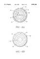
- FIGS. 6A and 6Bare distal side views of the reverse flow pump unit.
- FIGS. 7A-7Care side and sectional views of a rotor for a reverse flow pump having a hub and blade portions.
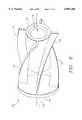
- FIG. 8is a perspective view of a hubless rotor for a reverse flow pump having a central passageway and blade portions.
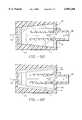
- FIGS. 9A-Eare sectional views of various pump housings with their respective rotors and relative flow patterns.
- FIG. 10is a simplified sectional side view of the drive unit for a reverse flow pump assembly.
- FIG. 11is a simplified perspective view of a conduit formed by conventional techniques showing a clamped vessel and an attached conduit.
- FIG. 12is a simplified sectional perspective view of a reverse flow pump assembly positioned within the conduit shown in FIG. 11.
- FIG. 13is a simplified sectional side view of a reverse flow system where the pump assembly is positioned external to a blood vessel graft.
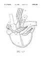
- FIG. 14is a sectional view of a heart and its respective chambers and valves including the placement of an inner cannula and an outer conduit for assisting the transport of blood between different regions of the heart.
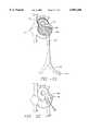
- FIG. 15is sectional view of the heart showing a portal formed in the aorta for the placement of the outer conduit and the inner cannula which also includes inflatable balloons positioned in different regions of the heart.
- FIG. 16is a sectional view showing the positioning of the inner cannulas and outer conduits of multiple circulatory support systems in different heart regions.
- FIG. 17is a sectional view showing a dual circulatory support system supporting both the left and right side of the heart.
- FIG. 18is a sectional view of a dual circulatory support system further including inflatable balloons and ports formed along the inner cannula that are positioned in different regions of the heart.
- FIG. 19is a sectional view of the heart illustrating a circulatory support and stabilization apparatus embodying multiple aspects of the present invention including at least one inflatable balloon in a heart region, a balloon within a heart chamber having another surrounding inflatable balloon, and further including additional openings formed along the inner cannula.
- FIG. 20is a sectional side view of a stabilization balloon with an inflation conduit.
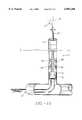
- FIG. 21is a stabilization system provided in accordance with the present invention that is introduced through a femoral artery.
- FIG. 22is an illustration of the exterior view of the heart and a forked instrument used to stabilize an external area of the heart.
- FIG. 23is a partial sectional view of the heart and a stabilization system used in cooperation with an intravascular pump.
- FIG. 24is a partial sectional view of the heart and a stabilization system used in cooperation with extracorporeal pump.
- the fluid transport system 10may comprise an inner cannula 20 coaxially aligned with an outer conduit 30, and a reverse flow pump 50.
- the reverse flow pump 50may direct bodily fluids such as blood through the inner cannula 20 to the outer conduit 30, and then throughout other regions of the body.
- the inner cannula 20may be arranged to function as an inlet conduit designed to assist the delivery of blood and other bodily fluids to the pump 50 while the outer conduit 30 may transport fluid away from the pump 50.
- the relative functions of the inner cannula and outlet conduitmay be exchanged depending on the desired positions of the distal opening 22 of the inner cannula 20 and the distal opening 32 of the outer conduit 30, and the direction of flow controlled by the pump 50.
- the inner cannula 20 in FIG. 1may be formed with a distal opening 22 and a proximal opening 24.
- the distal opening 22When positioned for use during heart surgery, for example, the distal opening 22 may be disposed in a heart chamber through major blood vessels such as the left ventricle.
- blood entering the distal opening 22 of the inner cannula 20is transported to the pump 50 which then directs the blood through the outer conduit 30 to another blood vessel or region of the heart.
- the inner cannula 20may be tubular and preferably made of flexible, biocompatible material such as silicone, and may be reinforced with other material such as steel wire to provide sufficient radial stiffness to resist collapsing.
- the tip 25 of the inner cannula 20may be chamfered and relatively flexible, or not reinforced, in order to provide greater flexibility and improved advancement of the inner cannula 20 through relatively small vessels or chambers that reduces trauma to surrounding tissue.
- the inner cannula 20may also have a plurality of openings 27 formed near its tip 25 to allow blood to flow into the inner cannula 20, particularly when the distal opening 22 may become occluded or otherwise obstructed.
- a catheter guide wiremay also be extended through the cannula openings 27 to dispose the inner cannula 20 at desired locations throughout the body including the heart region.
- the inner cannula 20may be formed relatively straight or with a permanent bend having a 10 to 120 degrees curved portion to facilitate installation and removal from a blood vessel or chamber.
- the inner cannula 20may also be formed of radiopaque material added or printed on its surface for visibility when exposed to X-ray radiation.
- the outer conduit 30 of the fluid transport systemmay be formed with a distal opening 32 and a proximal opening 34.
- the outer conduitmay also be tubular and made of flexible, biocompatible material such as silicone, and may be reinforced with other material such as steel wire to provide sufficient radial stiffness to resist collapsing.
- the distal opening 32 of the outer conduit 30may be extended through a portal 91 to form a closed circuit between the inner cannula 20 and outer conduit 30.
- the outer conduit 30is an introducer, or a vascular graft, such as a DacronTM graft, or any other commercially available grafts or synthetic conduits used.
- the proximal end of the outer conduit 30may be further connected to an elongated cylindrical body 40 for positioning and housing of other pump components.
- the device represented in FIG. 1may further comprise an inflow cannula 20 attached to a housing cap 60 fitted over a housing body 52, which houses a rotor 70 coupled to a drive unit 80.
- the housing cap 60may further comprise a base member 61 and an inlet neck 62 which may be separate components joined by welding or similar techniques, or may form a unitary body.
- the base member 61 and the inlet neck 62are preferably concentric to each other.
- Outflow windows 64may also be positioned relatively outwardly to inlet neck 62, and are preferably circumferential and symmetrical to inlet neck 62.
- the outside diameter of the housing cap 60is preferably matched to the inside diameter of the housing body 52 for a close tolerance fit, or any other method for attaching the housing cap 60 to the housing body 52.
- the housing body 52 and the housing cap 60may also form a unitary body.
- the outside diameter of the pump 50may match the inside diameter of a graft 30 so that a hemostatic seal is maintained between the outside diameter of the housing body 52 and the inside diameter of the graft 30. It should be noted again that the present invention may transport and control blood or any other bodily fluid.
- the pump assembly of the fluid transport apparatusincludes a reverse flow pump 50 with coaxially aligned or concentric inlet and outlet ports.
- the reverse flow pump 50 for this particular embodiment of the present inventionfurther includes a rotor 70 axially aligned inside a cylindrical-shaped housing body 52.
- the rotor 70is connected to a drive shaft 81 which is rotated at variable rates of relatively high speed by the driving unit 80.
- the distal opening of the housing body 52 of the pump 50may be covered with a housing cap 60.
- the housing cap 60is preferably constructed of stainless steel or rigid polymer and may be formed with a plurality of outflow windows 64.
- the outflow windows 64may be radially aligned around an inlet neck 62 formed in the base member 61 of the housing cap 60.
- the housing body 52 illustrated in this embodiment of the present inventionis generally cylindrical-shaped and includes a longitudinally and concentrically aligned inlet tube 55.
- the inlet tube 55may be integrally attached at one end to the base plate 53 and include a centrally aligned distal opening 56.
- a plurality of radially aligned cut-outs 57may also be formed along various portions of the inlet tube 55 to permit the passage of fluid.
- a rotor 70may be disposed longitudinally inside the inlet tube 55 as shown in FIG. 2. During operation of the fluid control apparatus in this configuration, the rotor 70 is rotated by the driving unit 80 through an opening or hole 54 in order to direct fluids such as blood from the inlet tube 55 out through the cut outs 57.
- the outside diameter of the inlet tube 55is preferably smaller than the inside diameter of the housing body 52 which creates a passageway 59 between the inlet tube 55 and the housing body 52.
- a housing cap 60is attached to the distal opening of the housing body 52.
- the housing cap 60may include a circular or disc shaped base member 61 designed to fit over the housing body 52.
- a cylindrical inlet neck 62may also be formed perpendicular to and centrally aligned to the base member 61.
- the outside diameter of the inlet neck 62is smaller then the inside diameter of both inner cannula 20 and the outer conduit 30 which forms another passageway 65 for the reverse flow of fluid such as blood.
- the inlet neck 62may also be joined temporarily or permanently to the proximal opening 24 of the inner cannula 20 by bonding or welding, or may even be integrally formed.
- the passageway 59 and the outflow windows 64 of the housing cap 60may be aligned with passageway 65 when the housing cap is assembled with the housing body 52.
- the fluid transport apparatus 10 shown in FIGS. 1 and 2may further include an elongated cylindrical body 40 connected to the proximal opening 34 of the outer conduit 30.
- the elongated body 40may house both the pump 50 and the drive unit 80.
- the cylindrical body 40may be formed with various dimensions to conveniently provide further assistance in positioning the apparatus 10 in a desired location.
- the distal opening 22 of the inner cannula 20 and the distal opening 32 of the outer conduit 30may be spaced apart and located in different blood vessels, for example, or on opposite sides of a heart valve so that blood may be pumped from one blood vessel or chamber to other regions of the heart.
- the inner cannula 20 and the outer conduit 30may be coaxially aligned and formed with a sufficient length so that only one portal opening may be required into a major blood vessel, chamber, or any other body passageway.
- the lengths of the inner cannula 20 and outer conduit 30may further be varied in accordance with particular applications such as open heart surgery, or during closed heart or other laproscopic procedures which involve forming other openings to provide percutaneous access to inner body regions.
- a positioning rod 273may be used to allow the transmission of torque or other force from positioning rod proximal end to the drive unit 80 (see FIG. 10) without any significant dampening.
- the positioning rod 273is preferably made from a metal or relatively stiff polymer and may comprise a central passage 275 extending the entire length of the positioning rod 273 and used for passing a guiding element 28, such as a guide wire or a catheter or like devices, through its center.
- the central passage 275 of the positioning rod 273may form a continuation of a central passage formed in the shaft of drive unit 80, and may be used for passing electrical wire 272 or like elements to the drive unit.
- the central passage 275 of the positioning rod 273is also preferably concentric with the outside diameter of positioning rod 273.
- the distal portion of the positioning rod 273may be matched to a groove 205 formed in the drive unit 80 to form a press fit, or to attach to the drive unit by welding, bonding or forming a unitary part.
- the proximal end of the positioning rod 273may further comprise two handles 274 to assist in the handling of the positioning rod during placement of the pump 50, and to prevent pushing the positioning rod 273 past the handles into a conduit.
- the central passage 275 of the positioning rod 273may therefore be removed or may simply provide for passing wires, tubes or similar accessories needed by the drive unit 80.
- the inner cannula 20may simply be advanced by itself into a vessel or chamber.
- FIGS. 3 and 4further illustrate silicone plugs 298 and 299 that may also be used to assist in sealing the pump, and may be formed with resilient flexible material such as silicone or like material.
- the outside diametermay be matched to the inside diameter of an outer conduit.
- Central holes 296 and 297 of the distal silicone plugs 298 and 299are relatively concentric to their outer diameter.
- Grooves 294 and 295may be formed circumferentially and midway between the proximal and distal face of the silicone plugs.
- Slits 292 and 293may extend through the entire length of the silicone plugs and extend from the outside surface of the silicone plugs to the central holes 296 and 297.
- the housing body 52is preferably tubular and includes a concentric inlet tube 55.
- a passage 59is thereby formed for blood or other fluid to flow within.
- the passage 59 of the housing body 52 and the outflow windows 64 of the housing cap 60may be aligned when the housing cap and the housing body are assembled coaxially.
- the inlet tube 55may comprise multiple cut-outs 57 at its proximal end to connect the passage 59 with the inlet tube 55.
- the profile of the inlet tube 55is not necessarily cylindrical and may vary in shape to match the outside profile of the rotor 70. Both profiles may be matched and varied according to pump design, i.e.
- an axial pumpmay have a cylindrical profile or a centrifugal pump may have a overall conical profile.
- a clearance between the inlet tube 55 profile and the rotor 70should exist to permit the rotor 70 to rotate without contacting the walls of the inlet tube 55.
- the inlet tube cut-outs 57may be generally circular, and may depend on the rotor and pump category or application.
- the proximal end of the inlet tube 55may be pressed into a matching groove 51 of the base plate 53.
- the base plate 53may comprise a groove 51 that is preferably concentric with the base plate 53 circumference, and a central hole 54 that is preferably concentric with the groove 51.
- the outside diameter of the base plate 53may be matched to the inside diameter of the housing body 52 to provide an interference fit to hold the base plate 53 and the housing body 52 together.
- the base plate 53 and the housing body 52may be formed of a unitary part or a multiple parts joined together by known techniques such as welding, bonding, or like techniques.
- the housing body 52 proximal endmay be attached to the distal end of drive unit 80.
- FIGS. 6A and 6Bare distal side views of the reverse flow pump unit.
- the housing cap 60is illustrated as having an inlet neck 62 and outflow windows 64.
- the inner cannula 20circumferentially surrounds the inlet neck 62 to direct fluid towards pump unit.
- the shape and relative number of windows 64 in the housing cap 60may of course vary. Although shown as a substantially concentric circular configuration, the particular shape of the housing cap 60 and inlet neck 62 may also vary.
- the rotor 70 within the housing body 52may be configured and rotate in a direction that would permit fluid to enter the pump through the housing windows 64 and directed away from the pump through the neck 62 of the housing cap.
- FIG. 6Billustrates yet another variation of the housing cap 60 for the pump unit, and may be selected to cooperate in particular with the operation of a hubless rotor (shown in FIG. 8) for the reverse flow pump.
- the housing cap windows 64are shown to be circumferentially surrounded by a centrally located housing cap neck opening 62, the spacing, position and geometry of these passageways may be varied.
- the housing cap neck opening 62may also vary in size and accommodate various inner cannula diameters.
- FIGS. 7A-C and 8illustrate various configurations of a rotor 70 that may be used in a reverse flow pump or any other type of fluid transport apparatus.
- the rotor 70may comprise a single or multiple blades 72 extending from a longitudinally aligned central hub 74.
- the blades 72 of the rotor 70assist in directing and controlling fluid direction.
- the reverse flow pumpmay generate flow rates of up to 8 or 9 liters per minute depending upon the particular pump dimensions and configuration, and is fully capable of supporting circulatory functions of the heart.
- the rotor 70is preferably an axial or a centrifugal hydraulic rotor, and profiled to provide lift to surrounding fluid when the rotor is rotated.
- a central rotor passage 73may extend the entire length of the rotor 70 and preferably forms a continuation of central passage 82 of drive unit 80.
- the central rotor passage 73 of the rotor 70may be left open or closed at the distal end of passage 73 with a gland valve 77 or similar closure entities to help keep blood or fluid outside of the passage.
- the disclosed gland valve 77is presented as an example and is not meant to be the only method that may be used in keeping the fluid outside of passage 73 of the rotor 70.
- Gland valve 77may be made from a flexible and resilient material such as silicone.
- the gland valve 77may further comprise a central conical opening 75 with a diameter of 0.040 inches at the proximal end of the valve gland and a slit 71 at the distal end of the gland valve.
- the slit 71may allow the passage of commercially available guide wires or similar devices for guiding the pump to its intended placement, and may also close and provide sufficient hemostasis when the guide wire or similar devices are removed from the gland valve 77.
- the central rotor passage 73 of the rotor 70may be removed entirely, and the gland valve 77 may be replaced with a conical or bullet shaped metallic or polymeric cap that is similar to the outside profile of the gland valve and formed without a slit 71.
- a hubless rotor 170may be selected for the reverse flow pump system.
- the hubless rotor 170may include a central portion 171 with an open central passageway 173 to permit the directional flow of fluid relative to the pump and an external surface with rotor blades 172 to reverse and direct the flow of fluid away from the pump.
- a base portion 174 and the rotor blades 172may be selected to position and support the center portion 171 of the hubless rotor 170.
- the base portion 174may be disc shaped and may include a shaft 176 that is directly or indirectly connected to a rotor drive unit.
- the blades 172 of the illustrated embodimentalso support the center portion 171, it is understood that the supporting members may also be separately formed from the blades.
- the central portion 171 of the hubless rotormay be generally formed with a cylindrical geometry or other suitable configurations to permit the directional flow of fluid through the center region of the hubless rotor 170 and the reverse flow of fluid along the relatively outer region of the rotor.
- the particular rotor blades 172 shown in FIG. 8are generally formed in spiral or helical pattern, but may similarly have other configurations to effectively direct fluid to enter and exit the pump.
- FIGS. 9A-Eillustrate several simplified cross sections of various embodiments of the present invention.
- Each of the illustrated reverse flow pumpsessentially consist of an outer pump housing and a rotor.
- the pumpfurther consists of an inlet passageway and a separate outlet passageway to direct the flow of fluid as indicated by the arrows included in the figures for purposes of illustration.
- the direction of fluid flowmay be reversed by changing the direction of the rotor movement or by varying the rotor blade configuration.
- an additional interior compartment 160is included within the outer pump housing 152.
- the interior compartment 160may be formed with walls 162 or 164 that surround at least a portion of the rotor 70.
- the interior compartment 160may alternately be described as an inlet tube when fluid is drawn into the pump 50 within this region before being expelled through the region defined by the outer pump housing 152 and the interior compartment.
- the inlet compartment 160 and the pump housing 152 shown throughout FIGS. 9A-E in sectionare preferably cylindrical, they may of course be altered accordingly for different applications.
- the reverse flow pump shown in FIG. 9Amay be described as an axial flow pump in view of the generally axial direction of the fluid flow relative to the shaft 76 of the rotor.
- the walls 162 of the interior compartment 160extend circumferentially around the rotor 70 to direct the fluid in an axial direction towards the base 154 of the pump housing 152 before being directed away from the pump 50 in the region defined by the interior compartment 160 and the outer pump housing 152.
- the reverse flow pump shownmay be described as a centrifugal flow pump in accordance with the general outwardly direction of the fluid flow relative to the shaft 76 of the rotor 70.
- the walls 164 of the interior compartment 160extend around a portion of the rotor 70 to direct the fluid in a general direction towards the housing walls 156 of the pump housing 152 before being directed away from the pump 50 in the region defined by the interior compartment 160 and the outer pump housing 152.
- FIG. 9Cillustrates another variation of the present invention that includes a reverse flow pump 150 with a hubless rotor 170.
- the hubless rotor 170basically consists of a central portion 171 that is positioned within the pump housing 152 by supporting members and a rotor base plate 174.
- the rotor 170may also be formed with a tapered opening 178 corresponding to a tapered opening 153 formed in the housing cap 60 to form a relatively close fit.
- the hubless rotor 170 of the reverse flow pumptends to draw fluid entering the pump away from the unit so as to reduce the direct impact of the fluid against housing walls or the base of the pump.
- a reverse flow pump with a hubless rotormay be characterized as both an axial and a centrifugal flow pump that embodies characteristics of each configuration.
- a relative degree of improved efficiencyhas been observed with the hubless rotor configuration shown in FIG. 9C as compared to the rotor designs illustrated in FIGS. 9A and 9B. Satisfactory flow rates are achieved nonetheless with these and other rotor configurations for the present reverse flow pump.
- the various rotor designs that may be used in accordance with the principles of the present inventioninclude rotors having central passageways with externally formed blades, internally formed blades, or with no blade portion at all.
- a hubless rotoris shown with external blades in partial conical form.
- the periphery of the rotor 170 in this variationgenerally conforms to the inner surfaces of the pump housing 152 while still permitting the passage of fluid around the outer surface of the rotor.
- a hubless rotor 170may also have blades formed internally within the central portion 171 (not shown), or with no rotor blades as shown in FIG. 9E which may be referred to as a shear pump design.
- the reverse flow pump 150 and rotor assemblies shown in FIGS. 9C-Egenerally permit fluid to travel through the center of the rotor 170 ordinarily occupied by a central hub.
- the open passageway 173 formed in the central portion 171 of the hubless rotor 170permits fluid to be drawn into the reverse flow pump 150 and subsequently directed away from the pump. As indicated by the directional arrows drawn in FIGS. 9C-E, the open passageway 173 may be aligned with the inlet passageway 158 of the pump housing 152, and the region external of the central portion 171 of the hubless rotor 170 may be aligned with the outlet passageway 159 of the pump 150.
- FIG. 10illustrates a drive unit 80 that may be used in accordance with the present fluid control and delivery system.
- the drive unit 80may be a miniature electric motor with an outside diameter equal to or less than the outside diameter of a housing body.
- the drive unit 80may also be a pneumatic driven turbine that is used to transform energy from a pressurized source to a rotary motion of shaft 81 or any other device that could impart rotation.
- the proximal face of the drive unit 80may comprise a groove 205 for attachment to the distal end of a positioning rod 273 (shown in FIGS. 3 and 4).
- a central passage 82 with a diameter of approximately 0.040 inchesmay also extend through the entire length of the shaft 81.
- the shaft 81may be coupled directly or indirectly to a rotor and transmit any shaft rotation to rotor rotation.
- a blood seal 84may be attached to the drive unit 80 and may comprise a central cavity 83 containing a biocompatible lubricating fluid, such as nutrilipid, dextrose solution, glycerin, or alike.
- the blood seal 84may further comprise two thin lips 88 that engage the outside diameter of shaft 81 to form a closed chamber to retain the lubricating fluid inside the central cavity 83 during the pump operation.
- Alternate blood seal designs well known in the artmay also be used in the drive unit 80.
- a 40% dextrose solutionmay also be used as a lubricating fluid with a continuous infusion of dextrose into the seal area.
- an electric stator 89, a magnetic rotor 90 and two bearings 78may be used in a conventional method to transform electric energy into rotational motion.
- the central passage 82 formed in the shaft 81 of the drive unit 80may be removed or used for functions other than a passage for a guiding element.
- the installment of fluid transport apparatusoften includes the anastomosis of the distal end of the outer conduit 30 to the sides of a targeted blood vessel or chamber using thoracoscopic suturing, or microstapling.
- the vessel or wall portionPrior to suturing the outer conduit 30 to a blood vessel or cavity wall, the vessel or wall portion may be isolated by using a C-clamp, thoracoscopic clamps, or any other type of similar clamp 300 that is capable of assisting in forming small ports into the body of a patient, and preferably capable of isolating only a section of the wall without complete occlusion of the vessel.
- the outer conduit 30is inserted into the portal.
- a suturemay be used to secure the outer conduit 30 in place relative to the portal 91.
- a commercially available high stiffness guide wire 28may also be passed through the outer conduit 30 to assist in the placement of the inner cannula 20.
- the outer conduit or graft 30may also be of sufficient length to accommodate the pump 50 from the distal end of cannula 20 to the proximal end of the positioning rod 273. Alternatively, the pump may be positioned externally relative to the outer conduit (as shown in FIG. 13).
- the outer conduitmay be filled with saline solution, and the pump may also be primed, if desired, to substantially remove the presence of air from the pump and the outer conduit.
- the driving unit 80may then be installed in a proximal position relative to the pump 50.
- a proximal silicone plug 298may be mounted on the positioning rod 273 and advanced to seal the outer conduit 30 and the driving unit 80.
- a suturemay be tied on the outside of the outer conduit 30, and in the area of the graft overlaying proximal groove 295 of the proximal silicone plug 298 to secure the plug to the proximal part of the conduit.
- the C-clampAfter the installation of the fluid transport apparatus 10, the C-clamp is released gradually, and homeostasis at potential bleeding sites are visually examined unassisted or with the aid of a viewing scope. Upon achieving acceptable homeostasis or stability, the C-clamp 300 may be completely released but should be kept in ready position to clamp the anastomosis site in case of an emergency.
- a guide wire 28may be also advanced with the help of imaging techniques to dispose the distal end of the inner cannula 20 in the desired blood vessel, heart chamber or other body cavity. The guide wire 28 may be inserted and positioned to a desired location before being passed through an opening or orifice formed on the distal end of the inner cannula 20.
- the distal end of the inner cannula 20may be guided to a location before removing the guide wire 28.
- the pump 50may need to be advanced in the outlet conduit 30 by pushing the positioning rod 273 into the outer conduit or graft.
- the distal silicone plug 299may be advanced to the proximal side of the drive unit 80 and secured in place by a suture, a laproscopic clamping device, or other similar techniques.
- a suture or a laproscopic clamping devicemay be employed to hold the apparatus in position or the outside diameter of the housing body 52 may also be secured to the outer conduit or graft 30 using similar techniques to secure the distal plug 299.
- the guide wire 28may be removed before the pump is activated. Alternatively, the guide wire 28 may be removed immediately after positioning the inner cannula 20 relative to the outer conduit 30. The pump 50 may then be secured to the proximal ends of the inner cannula 20 and the outer conduit 30. Accommodations for passage of the guide wire 28 through other components of the fluid transport apparatus may thus be avoided.
- the pumping rate of the pump 50may be adjusted to maintain sufficient circulation or to accommodate changes in circulatory demand.
- the pump 50may also be equipped with sensing devices (not shown) for measuring various body conditions such as the blood pressure, the presence of blood, or other parameters that would suggest the need for altering the flow rate of the fluid transport apparatus 10.
- the apparatusmay include pressure sensors along the inner cannula 20 so that a preset pressure change would signal the need to change the pumping capacity of apparatus.
- the pump 50may include sensors to sense the pressure at the distal end of the cannula 20 so that a preset pressure change could signal the need to change the pumping capacity of pump.
- a controller used with the apparatus 10may provide warning signals or automatically decrease the flow rate of the apparatus until returning to a preset pressure at the inner cannula.
- the suture or laproscopic clamping device for the apparatusis first disconnected enabling it to be moved.
- the silicone plugs 298 and 299 and housing body 52are freed and removed.
- the pump 50is then retracted through the outer conduit 30, and the C-clamp 300 is engaged and clamped to isolate the portal site.
- the anastomosismay be restored using common thoracoscopic techniques for suturing or stapling before being removed.
- the surgical siteis closed using known surgical techniques.
- a method for effectively transporting blood between regions of the heartmay basically include: selecting a blood flow support apparatus 10 including a coaxially aligned inner cannula 20 and an outer conduit 30, a coaxially aligned reverse flow pump 50 disposed therebetween; forming a portal 91 in a blood vessel in communication with the heart; connecting the outer conduit through the portal; inserting the inner cannula through the outer conduit and the portal so that the distal opening 22 of the inner cannula is disposed on opposite sides of a desired heart valve or region relative to the distal opening 32 of the outer conduit, and activating the reverse flow pump so that blood adjacent to the distal opening of the inner cannula is pumped through the inner cannula to the outer conduit.
- a guide wire 28may be advanced with the help of imaging techniques to any of the heart chambers or vessels.
- a commercially available high stiffness guide wire 28may be used and passed through the central passage of the positioning rod 273 proximal end, to the distal end of the rotor 70, passing through the gland valve 77, and through the cannula 20.
- the pump 50 and the guide wire 28may be are inserted into a graft or outer conduit 30 and advanced to the clamped section of a vessel.
- the pump 50may be sealed and attached to the outer conduit 30 with an external drive unit 80.
- This variationincludes the use of a pump 50 that is kept outside the skin of a patient 94 wherein the pump attaches to the proximal end of graft 30.
- the outer conduit or graft 30is anastomosed as described above, but the pump 50 is not inserted into the inside diameter of this outer conduit. Rather, only the distal end of the main outflow housing 52 is inserted into the outer conduit 30 and secured by using a suture tied around the outside diameter in the area overlapping the outer conduit.
- the pump 50outflow discharges from outflow windows 64 into the inside diameter of outflow housing 52.
- An advantage offered by this embodiment of the present inventionis the use of a pump 50 that is kept outside the skin 94.
- This variationeffectively avoids the requirement for both the pump housing body 52 outside diameter and the outside diameter of the drive unit 80 to be smaller than the inside diameter of the outer conduit 30.
- the outside diameter of the pump rotor and all internal parts dimensionsmay therefore be larger than described earlier, which may simplify the pump designs, and may enable the device capacity to be increased significantly without increase in pump design sophistication.
- this variationmay obviously be used with patients that already have their body open for a surgical procedure wherein graft 30 is not passed through the skin to access a vessel, heart, cavity, or any other body region.
- FIG. 14is an illustration of another cardiac support apparatus 10 that may be used in accordance with the concepts of the present invention.
- the illustrated fluid transport apparatus 10provides cardiac support to the right side of the heart by pumping blood from the right ventricle 97 to the pulmonary artery 98.
- a portal 91is formed in the pulmonary artery 98 through which the distal end of the outer conduit 30 is extended.
- the inner cannula 20may be inserted into the portal 91 and through the pulmonic valve 95 to reach the right ventricle 97.
- Both the inner cannula 20 and the outer conduit 30may of course be connected to a reverse flow pump, and may be further selected of appropriate lengths to facilitate endoscopic procedures or to provide on-site cardiac support which minimizes exposure of circulated blood with foreign surfaces.
- FIG. 15is an illustration of another variation of a cardiac support apparatus 10 adapted particularly for left heart assistance.
- An outer conduit 30is attached to a portal 91 formed in the aorta 92, and an inner cannula 20 is continuously extended through the portal 91, the aortic and mitral valves 96, 99, respectively, and eventually the left atrium 93.
- An optional balloon 85may also be disposed on the outside surface of the inner cannula 20 to seal, or to deliver a cool fluid or mediation to the adjacent tissue.
- the balloon 85may be disposed around the inner cannula 20 and connected to a conduit 86 through which air, or a suitable coolant, or mediation may be transported to the balloon 85.
- a plurality of perforations 87may be formed on the surface of the balloon 85 to allow medication to be delivered to the surrounding tissue.
- the inflatable balloon 85may also create a separation in a body cavity to provide for the transport of fluid between the regions surrounding the distal end of the inner cannula 20 and the distal end of the outer conduit 30.
- the inner cannula 20does not necessarily pass through body compartments separated by valves or other separating body members.
- the inflatable balloon 85may isolate an organ such as a kidney or seal a region of the body when pressurized within a body cavity or vessel. Fluid may be delivered under pressure from the inner cannula 20 to the region surrounding the outer conduit 30. Accordingly, the inflatable balloon 85 may be used alone or in conjunction with other variations of the present fluid transport and control system.
- FIG. 16Another variation of the present invention is the insertion of a heart pump into the left heart side and simultaneously inserting a second heart pump into the right heart side of the patient as shown in FIG. 16.
- An inner cannula 20may be placed in the left atrium and the second cannula 120 in the right ventricle.
- the inflow cannula tip 25 of cannula 20 placed in the left heart sidemay be advanced and placed in the left ventricle, left atrium, or any of the left heart vessels.
- the inflow cannula tip 125 of the second cannula 120may be placed in the right heart side and advanced into position in the right ventricle, right atrium, or any of the right heart vessels.
- the circulatory functions of the heartmay be supported in open or closed heart surgery without necessarily immobilizing or arresting the heart which would further require extensive surgical procedures and apparatus.
- FIG. 17illustrates another variation of the present invention involving the insertion of a left heart pump into the left side of the heart, and simultaneously inserting a second heart pump into the right side of the heart.
- a cannula 20may be placed in the left atrium and a second cannula 120 from another pump may be placed in the pulmonary artery and passed through the vena cava, right atrium, and right ventricle.
- the heart pumps shownare similar except that cannula 20 of the left heart pump may function as inflow cannula while cannula 120 of the second pump may function as an outflow cannula as earlier described.
- An outer conduit 30 when used with left heart pumpmay function as an outflow cannula while the outer conduit when used with the second pump may function as an inflow cannula.
- the second cannula 120may have all of characteristics and capabilities of the first cannula 20.
- the cannula 20 in this embodimentmay comprise a distal balloon 185 for occluding the mitral valve, and a proximal balloon 186 for occluding the ascending aorta below the anastomosis site, and an orifice 187 for injection or suction of a fluid.
- Another cannula 120 from a second pumpmay also comprise a distal balloon 183 for occluding the pulmonic valve.
- the second inner cannula 120 in this variation of the present inventionserves as an outflow conduit while the outer conduit 130 serves as an inflow conduit.
- Another alternativeprovides for the occlusion of the mitral valve and the pulmonic valve of the patient, but not the occlusion of the ascending aorta.
- the heartBy operating both pumps, the heart may be partially or completely unloaded, and arrested by infusing drugs into the heart itself through the fluid orifice 187. As a result, this procedure provides a minimally invasive and less traumatic technique to maintain heart functions, and may be particularly suitable for endoscopic applications.
- FIG. 19illustrates another variation of the present invention which includes a cannula 20 extending through an outer conduit 30.
- the cannula 20 of the pumpmay also be formed with multiple balloons on the outside diameter of cannula 20 that may be inflated through separate or common ports located outside the patient's body with air or fluid.
- a balloon 186 that may be formed at any position along cannula 20may be inflated through a port and passageway 194 located outside of the patient's body with air or fluid to force a heart cavity to stretch.
- the balloon 186may also be inflated to occlude a vessel, a cavity, a heart chamber, or a wound in any tissue or organ, or it may be filled with air or fluid of a lower or higher temperature than the surrounding tissue to cool or to heat a vessel, a cavity, a heart chamber, or a wound in any tissue or organ.
- the balloon 186may also be inflated to hold a heart valve open, to hold a flap open, or to hold any internal structure in a desired position.
- Another balloon 190may also be inflated through a port and passageway 196 located outside the patient body with air or fluid and force this second balloon 190 against the wall of a vessel, a cavity, a heart chamber, or a wound in any tissue or organ.
- This balloon 190may further include a surrounding balloon 192 that may be perforated and used to inject drugs, cardioplegia solutions to arrest the heart, or any other therapeutic agent through the balloon perforations to treat, affect or alter the tissue in contact with balloon.
- the surrounding balloon 192may similarly be inflated through a common port with its adjoining balloon 190, or a separate port and passageway 198 located outside the patient body with a variety of drugs or therapeutic agents.
- the ports and passageways of all the aforementioned balloonsmay be formed adjoining to or concentric with the cannula 20.
- An orifice 187may also be formed in the cannula 20 and located between two balloons to serve as an inflow port in conjunction with the cannula tip 25, or when the cannula tip may become occluded.
- the orifice 187may also be positioned anywhere along cannula 20 surfaces.
- the orifice 187may alternatively be used as an injection port, a port for measuring pressure in areas proximal to the orifice or a suction port that could be accessed from a port located outside of the patient's body.
- the orifice 187 and the inner lumen of cannula 20may of course be separated, and may not affect each other and their respective functions.
- the stabilization system 410may basically comprise a stabilization cannula 411 with an inner passageway 414 for fluid transport that is formed of a reinforced wire 418 with a proximal end 413 and a distal end 415, an inflation lumen 412, and an inflatable stabilization balloon 440 attached to the outer surface of the cannula.
- the stabilization balloon 440may also be shifted relative to the stabilization cannula to allow the stabilization of different areas of the heart, and may be formed of two different devices, and not integral formed as one device, that are designed to work together to achieve the described function above.
- the balloon 440may be formed of permeable material that will allow diffusion of a fluid that may also be used to inflate the balloon towards the outside surface of the balloon.
- the fluidmay also contain a number of drugs used to affect the area in direct contact with the balloon 440 or be used to control the temperature of tissue in the proximity of the balloon.
- the stabilization cannula 411is preferably made from a thin wall elastomeric material, such as silicone or urethane, and may include encapsulated wire material 418 to provide some degree of kink resistance.
- the inflation lumen 412may be a tubular section connecting an open proximal end 417 with a miniature side opening 416, and a blocked distal end 419.
- the distal end 419may be blocked by adhesive or alike methods to contain any fluid in inflation lumen 412 from leaking out.
- the inflation lumen 412may be in communication with the balloon interior 442 via a small side opening 416 in inflation lumen 412.
- the inflation lumen 412may be in communication with the outside of the body through one of the catheter lumens 422. The injection of any fluid at the proximal end 417 or through catheter lumen 422 assists in the inflation of inflatable balloon 440.
- the stabilization apparatus 410 and a pump 420may be introduced into the body as shown in FIG. 21 through the femoral artery 430 with a catheter 428 linking the device to the exterior of the body.
- the catheter 428may be a multilumen catheter with separate lumens to drive the pump 420, to measure pressure in the vicinity of the catheter along its entire length, to deliver or remove fluid, to enable the passage of small diameter guides or leads, or to perform other similar functions.
- Other lumensmay be included in the catheter 428 to measure pressure, deliver or aspire fluid, for guide wire or tools passage, or usage of a catheter lumen.
- the stabilization cannula 411further includes a distal end 415 and a stabilization balloon 440 with an interior 442.
- the distal end 419 of the inflation lumen 412may be blocked and have an opening to inflate the balloon interior 442.
- the external surface of the heart 446may be stabilized, as shown in FIG. 22, by using commercially available tools 447 (such as CTSI Stabilizer) that may be forked to hold a specific section of the heart from moving outwardly.
- the stabilization cannula 411may be positioned within a ventricle or atrium. After proper positioning, a pump may be activated and take over the left ventricle function.
- the balloon 440may be inflated until the ventricle wall is restrained from inward movement. The heart wall therefore becomes relatively fixed and reduces any significant movement in order to allow the surgeon to perform delicate procedures such as suturing a still vessel.
- the balloon 440may also be inflated so as to not entirely occlude the area it occupies in order to allow blood or other liquids to flow around the balloon.
- the stabilization cannula 411 and balloon 440may also be positioned in an atrium instead of a ventricle to fixate the heart wall at the atrium level instead of the ventricle level.
- the right side of the heartmay be accessed through the femoral vein, the neck or arm arteries, through direct insertion into the right atrium or right ventricle, through the pulmonary artery, or any vein of the adequate size.
- a mechanical structuremay be employed instead of a balloon 440 to achieve the same stabilization described above.
- any mechanical fixationmay be used including hinged arms that have low profile during insertion, and may expand when advanced to the right position to provide support from the interior surfaces.
- this stabilization apparatus 410may further be used to hold the inside wall of an organ or a cavity such as the abdominal wall or hepatic conduits during surgery.
- FIGS. 23 and 24illustrate two different embodiments of the present invention.
- the placement of stabilization apparatus 410may be achieved by introducing the stabilization system alone, or with a pump 420, through the femoral artery 430 via direct aortic insertion, or through any other artery of adequate size, i.e., brachiocephalic, carotid, etc.
- the proximal end 413 or the distal end 415 of the stabilization system 410may be adapted to receive a blood pump 420 to aid in moving fluid between both ends of the conduit.
- the blood pumpis preferably mounted to the distal end 415 of the stabilization cannula 411.
- FIG. 24similarly illustrates positioning of another stabilization system formed in accordance with the present invention.
- An access conduit 433such as a DacronTM graft may be formed to receive an extracorporeal pump 421, or a reverse flow pump such as those described above, at the proximal end of the access conduit 433 and use the stabilization apparatus 410 for its inflow, and access conduit 433 for its outflow to result in a similar arrangement to the one described above and presented in FIG. 24.
- the placement of the access conduit 433may be achieved by common surgical methods used to graft a end-to-side graft.
- the stabilization systems shown in FIGS. 23 and 24illustrate only some of the various types of commercially available intravascular and extracorporeal pumps that are compatible or provided for by the present invention.
Landscapes
- Health & Medical Sciences (AREA)
- Heart & Thoracic Surgery (AREA)
- Vascular Medicine (AREA)
- Biomedical Technology (AREA)
- Engineering & Computer Science (AREA)
- Anesthesiology (AREA)
- Cardiology (AREA)
- Hematology (AREA)
- Life Sciences & Earth Sciences (AREA)
- Animal Behavior & Ethology (AREA)
- General Health & Medical Sciences (AREA)
- Public Health (AREA)
- Veterinary Medicine (AREA)
- External Artificial Organs (AREA)
- Surgical Instruments (AREA)
Abstract
Description
Claims (13)
Priority Applications (19)
| Application Number | Priority Date | Filing Date | Title |
|---|---|---|---|
| US08/891,456US6123725A (en) | 1997-07-11 | 1997-07-11 | Single port cardiac support apparatus |
| US08/933,566US6083260A (en) | 1997-07-11 | 1997-09-19 | Reverse flow transport pump and organ stabilization apparatus including related methods |
| DE19782288TDE19782288T1 (en) | 1997-07-11 | 1997-10-14 | Feed pump and organ stabilization device and corresponding procedures |
| EP97910989AEP0993312A1 (en) | 1997-07-11 | 1997-10-14 | Transport pump and organ stabilization apparatus including related methods |
| CA002301582ACA2301582A1 (en) | 1997-07-11 | 1997-10-14 | Transport pump and organ stabilization apparatus including related methods |
| AU48235/97AAU4823597A (en) | 1997-07-11 | 1997-10-14 | Transport pump and organ stabilization apparatus including related methods |
| PCT/US1997/018674WO1999002204A1 (en) | 1997-07-11 | 1997-10-14 | Transport pump and organ stabilization apparatus including related methods |
| GB0002930AGB2342866B (en) | 1997-07-11 | 1997-10-14 | Transport pump and organ stabilization apparatus including related methods |
| JP2000501794AJP2003524432A (en) | 1997-07-11 | 1997-10-14 | Transport pump and organ stabilizer and related methods |
| US09/462,656US6976996B1 (en) | 1997-07-11 | 1997-10-14 | Transport pump and organ stabilization apparatus including related methods |
| US09/481,730US6935344B1 (en) | 1997-09-19 | 2000-01-11 | Methods and systems for providing right and/or left heart support during cardiac surgery |
| PCT/US2000/001095WO2001078807A1 (en) | 1997-09-19 | 2000-01-14 | Integrated pump and cannula systems and related methods |
| AU2000235821AAU2000235821A1 (en) | 1997-09-19 | 2000-01-14 | Integrated pump and cannula systems and related methods |
| DE10084342TDE10084342T1 (en) | 1997-09-19 | 2000-01-14 | Integrated pump and cannula systems and related procedures |
| US09/889,442US6974436B1 (en) | 1997-09-19 | 2000-01-14 | Integrated pump and cannula system and related methods |
| US09/669,104US6858001B1 (en) | 1997-07-11 | 2000-09-25 | Single port cardiac support apparatus |
| US11/214,374US20050279370A1 (en) | 1997-07-11 | 2005-08-29 | Methods and systems for providing right and/or left heart support during cardiac surgery |
| US11/280,547US20060069299A1 (en) | 1997-09-19 | 2005-11-16 | Integrated pump and cannula systems and related methods |
| US11/312,087US20060100565A1 (en) | 1997-07-11 | 2005-12-20 | Transport pump and organ stabilization apparatus including related methods |
Applications Claiming Priority (2)
| Application Number | Priority Date | Filing Date | Title |
|---|---|---|---|
| US08/891,456US6123725A (en) | 1997-07-11 | 1997-07-11 | Single port cardiac support apparatus |
| US08/933,566US6083260A (en) | 1997-07-11 | 1997-09-19 | Reverse flow transport pump and organ stabilization apparatus including related methods |
Related Parent Applications (1)
| Application Number | Title | Priority Date | Filing Date |
|---|---|---|---|
| US08/891,456Continuation-In-PartUS6123725A (en) | 1997-07-11 | 1997-07-11 | Single port cardiac support apparatus |
Related Child Applications (4)
| Application Number | Title | Priority Date | Filing Date |
|---|---|---|---|
| US09462656Continuation-In-Part | 1997-10-14 | ||
| US09/462,656Continuation-In-PartUS6976996B1 (en) | 1997-07-11 | 1997-10-14 | Transport pump and organ stabilization apparatus including related methods |
| PCT/US1997/018674Continuation-In-PartWO1999002204A1 (en) | 1997-07-11 | 1997-10-14 | Transport pump and organ stabilization apparatus including related methods |
| US09/231,320Continuation-In-PartUS6532964B2 (en) | 1997-07-11 | 1999-01-13 | Pulmonary and circulatory blood flow support devices and methods for heart surgery procedures |
Publications (1)
| Publication Number | Publication Date |
|---|---|
| US6083260Atrue US6083260A (en) | 2000-07-04 |
Family
ID=35452491
Family Applications (9)
| Application Number | Title | Priority Date | Filing Date |
|---|---|---|---|
| US08/891,456Expired - LifetimeUS6123725A (en) | 1997-07-11 | 1997-07-11 | Single port cardiac support apparatus |
| US08/933,566Expired - Fee RelatedUS6083260A (en) | 1997-07-11 | 1997-09-19 | Reverse flow transport pump and organ stabilization apparatus including related methods |
| US09/462,656Expired - Fee RelatedUS6976996B1 (en) | 1997-07-11 | 1997-10-14 | Transport pump and organ stabilization apparatus including related methods |
| US09/481,730Expired - Fee RelatedUS6935344B1 (en) | 1997-07-11 | 2000-01-11 | Methods and systems for providing right and/or left heart support during cardiac surgery |
| US09/889,442Expired - Fee RelatedUS6974436B1 (en) | 1997-09-19 | 2000-01-14 | Integrated pump and cannula system and related methods |
| US09/669,104Expired - Fee RelatedUS6858001B1 (en) | 1997-07-11 | 2000-09-25 | Single port cardiac support apparatus |
| US11/214,374AbandonedUS20050279370A1 (en) | 1997-07-11 | 2005-08-29 | Methods and systems for providing right and/or left heart support during cardiac surgery |
| US11/280,547AbandonedUS20060069299A1 (en) | 1997-09-19 | 2005-11-16 | Integrated pump and cannula systems and related methods |
| US11/312,087AbandonedUS20060100565A1 (en) | 1997-07-11 | 2005-12-20 | Transport pump and organ stabilization apparatus including related methods |
Family Applications Before (1)
| Application Number | Title | Priority Date | Filing Date |
|---|---|---|---|
| US08/891,456Expired - LifetimeUS6123725A (en) | 1997-07-11 | 1997-07-11 | Single port cardiac support apparatus |
Family Applications After (7)
| Application Number | Title | Priority Date | Filing Date |
|---|---|---|---|
| US09/462,656Expired - Fee RelatedUS6976996B1 (en) | 1997-07-11 | 1997-10-14 | Transport pump and organ stabilization apparatus including related methods |
| US09/481,730Expired - Fee RelatedUS6935344B1 (en) | 1997-07-11 | 2000-01-11 | Methods and systems for providing right and/or left heart support during cardiac surgery |
| US09/889,442Expired - Fee RelatedUS6974436B1 (en) | 1997-09-19 | 2000-01-14 | Integrated pump and cannula system and related methods |
| US09/669,104Expired - Fee RelatedUS6858001B1 (en) | 1997-07-11 | 2000-09-25 | Single port cardiac support apparatus |
| US11/214,374AbandonedUS20050279370A1 (en) | 1997-07-11 | 2005-08-29 | Methods and systems for providing right and/or left heart support during cardiac surgery |
| US11/280,547AbandonedUS20060069299A1 (en) | 1997-09-19 | 2005-11-16 | Integrated pump and cannula systems and related methods |
| US11/312,087AbandonedUS20060100565A1 (en) | 1997-07-11 | 2005-12-20 | Transport pump and organ stabilization apparatus including related methods |
Country Status (8)
| Country | Link |
|---|---|
| US (9) | US6123725A (en) |
| EP (1) | EP0993312A1 (en) |
| JP (1) | JP2003524432A (en) |
| AU (2) | AU4823597A (en) |
| CA (1) | CA2301582A1 (en) |
| DE (2) | DE19782288T1 (en) |
| GB (1) | GB2342866B (en) |
| WO (2) | WO1999002204A1 (en) |
Cited By (103)
| Publication number | Priority date | Publication date | Assignee | Title |
|---|---|---|---|---|
| WO1999059652A1 (en) | 1998-05-15 | 1999-11-25 | A-Med Systems, Inc. | Pulmonary and circulatory blood flow support devices and methods for heart surgery procedures |
| US6478028B1 (en)* | 1999-01-21 | 2002-11-12 | Coroneo, Inc. | Surgical apparatus and method for performing transabdominal cardiac surgery |
| US20030023201A1 (en)* | 2001-04-25 | 2003-01-30 | A-Med Systems, Inc. | Systems and methods for performing minimally invasive cardiac medical procedures |
| US6709418B1 (en) | 1997-07-11 | 2004-03-23 | A-Med Systems, Inc. | Apparatus and methods for entering cavities of the body |
| US20040177162A1 (en)* | 2001-06-29 | 2004-09-09 | Wetzel Daniel Thomas | Multi-media jitter removal in an asynchronous digital home network |
| US20040191116A1 (en)* | 1996-10-04 | 2004-09-30 | Robert Jarvik | Circulatory support system |
| US6808508B1 (en)* | 2000-09-13 | 2004-10-26 | Cardiacassist, Inc. | Method and system for closed chest blood flow support |
| US6858001B1 (en) | 1997-07-11 | 2005-02-22 | A-Med Systems, Inc. | Single port cardiac support apparatus |
| US20050119599A1 (en)* | 1999-05-18 | 2005-06-02 | A-Med Systems, Inc. | Supplemental port for catheter perfusion of surgical site and methods of use |
| US20050148811A1 (en)* | 1997-07-11 | 2005-07-07 | A-Med Systems, Inc. | Single port cardiac support apparatus |
| US20050187425A1 (en)* | 2004-01-14 | 2005-08-25 | Scout Medical Technologies, Llc | Left ventricular function assist system and method |
| US6969379B1 (en) | 1998-08-27 | 2005-11-29 | A-Med Systems, Inc. | Intravascular cannulation apparatus and methods of use |
| US20060030809A1 (en)* | 2004-07-12 | 2006-02-09 | Amir Barzilay | Apparatus and method for multiple organ assist |
| US20060063965A1 (en)* | 1998-06-19 | 2006-03-23 | Aboul-Hosn Walid N | Apparatus and methods for entering cavities of the body |
| US7022100B1 (en) | 1999-09-03 | 2006-04-04 | A-Med Systems, Inc. | Guidable intravascular blood pump and related methods |
| US20060084912A1 (en)* | 2004-10-18 | 2006-04-20 | N.G.C. Medical S.P.A. | Apparatus for performing an aortal valvular surgery intervention on a beating heart |
| US20060178552A1 (en)* | 2005-02-10 | 2006-08-10 | Yossi Gross | Extracardiac blood flow amplification device |
| US20060195004A1 (en)* | 2005-02-28 | 2006-08-31 | Robert Jarvik | Minimally invasive transvalvular ventricular assist device |
| US20070010709A1 (en)* | 2005-07-08 | 2007-01-11 | Johannes Reinschke | Endoscopy capsule |
| US20070125392A1 (en)* | 2005-12-01 | 2007-06-07 | Sdgi Holdings, Inc. | Systems and methods of accounting for surgical instruments and disposables |
| US20070161845A1 (en)* | 2006-01-09 | 2007-07-12 | Cardiacassist, Inc. | Percutaneous right ventricular assist apparatus and method |
| US20080234537A1 (en)* | 2004-02-10 | 2008-09-25 | Yossi Gross | Extracardiac Blood Flow Amplification Device |
| US20090107511A1 (en)* | 2006-05-11 | 2009-04-30 | Yossi Gross | Implantable respiration therapy device |
| US7878967B1 (en)* | 2005-10-06 | 2011-02-01 | Sanjaya Khanal | Heart failure/hemodynamic device |
| US20110040241A1 (en)* | 2009-08-11 | 2011-02-17 | Dongfang Wang | Blood access assembly for artificial lung and right ventricular assist device |
| US20110160517A1 (en)* | 2009-12-31 | 2011-06-30 | Cardiacassist, Inc. | System for heart assist, cannula and method |
| US7998054B2 (en) | 1997-10-09 | 2011-08-16 | Thoratec Corporation | Implantable heart assist system and method of applying same |
| US8118724B2 (en) | 2003-09-18 | 2012-02-21 | Thoratec Corporation | Rotary blood pump |
| US8377036B2 (en) | 2007-09-14 | 2013-02-19 | Avalon Laboratories, Inc. | Cannula reinforcing band and method |
| US8485961B2 (en) | 2011-01-05 | 2013-07-16 | Thoratec Corporation | Impeller housing for percutaneous heart pump |
| US8535211B2 (en) | 2009-07-01 | 2013-09-17 | Thoratec Corporation | Blood pump with expandable cannula |
| US8540618B2 (en) | 2003-01-31 | 2013-09-24 | L-Vad Technology, Inc. | Stable aortic blood pump implant |
| US8591393B2 (en) | 2011-01-06 | 2013-11-26 | Thoratec Corporation | Catheter pump |
| US8597170B2 (en) | 2011-01-05 | 2013-12-03 | Thoratec Corporation | Catheter pump |
| US8721517B2 (en) | 2012-05-14 | 2014-05-13 | Thoratec Corporation | Impeller for catheter pump |
| US8821365B2 (en) | 2009-07-29 | 2014-09-02 | Thoratec Corporation | Rotation drive device and centrifugal pump apparatus using the same |
| US20140350328A1 (en)* | 2007-02-27 | 2014-11-27 | Miracor Medical Systems Gmbh | Catheter to assist the performance of a heart |
| US8992163B2 (en) | 2004-09-17 | 2015-03-31 | Thoratec Corporation | Expandable impeller pump |
| US9067005B2 (en) | 2008-12-08 | 2015-06-30 | Thoratec Corporation | Centrifugal pump apparatus |
| US9138518B2 (en) | 2011-01-06 | 2015-09-22 | Thoratec Corporation | Percutaneous heart pump |
| US9233223B2 (en) | 2007-06-26 | 2016-01-12 | Nordson Corporation | Coaxial venal cannula |
| US9308302B2 (en) | 2013-03-15 | 2016-04-12 | Thoratec Corporation | Catheter pump assembly including a stator |
| US9327067B2 (en) | 2012-05-14 | 2016-05-03 | Thoratec Corporation | Impeller for catheter pump |
| US9339597B2 (en) | 2012-02-07 | 2016-05-17 | Hridaya Inc. | Hemodynamic assist device |
| US9358329B2 (en) | 2012-07-03 | 2016-06-07 | Thoratec Corporation | Catheter pump |
| US9364592B2 (en) | 2004-09-17 | 2016-06-14 | The Penn State Research Foundation | Heart assist device with expandable impeller pump |
| US9381288B2 (en) | 2013-03-13 | 2016-07-05 | Thoratec Corporation | Fluid handling system |
| US9404505B2 (en) | 2008-12-05 | 2016-08-02 | Ecp Entwicklungsgesellschaft Mbh | Fluid pump with a rotor |
| US9421311B2 (en) | 2012-07-03 | 2016-08-23 | Thoratec Corporation | Motor assembly for catheter pump |
| US9446179B2 (en) | 2012-05-14 | 2016-09-20 | Thoratec Corporation | Distal bearing support |
| US9512852B2 (en) | 2006-03-31 | 2016-12-06 | Thoratec Corporation | Rotary blood pump |
| US9556873B2 (en) | 2013-02-27 | 2017-01-31 | Tc1 Llc | Startup sequence for centrifugal pump with levitated impeller |
| US9623161B2 (en) | 2014-08-26 | 2017-04-18 | Tc1 Llc | Blood pump and method of suction detection |
| US9638202B2 (en) | 2010-09-14 | 2017-05-02 | Tc1 Llc | Centrifugal pump apparatus |
| US9675738B2 (en) | 2015-01-22 | 2017-06-13 | Tc1 Llc | Attachment mechanisms for motor of catheter pump |
| US9675739B2 (en) | 2015-01-22 | 2017-06-13 | Tc1 Llc | Motor assembly with heat exchanger for catheter pump |
| US9694122B2 (en)* | 2003-01-31 | 2017-07-04 | L-Vad Technology, Inc. | Rigid body aortic blood pump implant |
| US9709061B2 (en) | 2013-01-24 | 2017-07-18 | Tc1 Llc | Impeller position compensation using field oriented control |
| US9759237B2 (en) | 2010-05-17 | 2017-09-12 | Ecp Entwicklungsgesellschaft Mbh | Pump arrangement |
| US9770543B2 (en) | 2015-01-22 | 2017-09-26 | Tc1 Llc | Reduced rotational mass motor assembly for catheter pump |
| US9771801B2 (en) | 2010-07-15 | 2017-09-26 | Ecp Entwicklungsgesellschaft Mbh | Rotor for a pump, produced with a first elastic material |
| US9827356B2 (en) | 2014-04-15 | 2017-11-28 | Tc1 Llc | Catheter pump with access ports |
| US9833550B2 (en) | 2003-08-08 | 2017-12-05 | Abiomed Europe Gmbh | Intracardiac pumping device |
| US9850906B2 (en) | 2011-03-28 | 2017-12-26 | Tc1 Llc | Rotation drive device and centrifugal pump apparatus employing same |
| US9872947B2 (en) | 2012-05-14 | 2018-01-23 | Tc1 Llc | Sheath system for catheter pump |
| US9878079B2 (en) | 2007-10-08 | 2018-01-30 | Ais Gmbh Aachen Innovative Solutions | Catheter device |
| US9907890B2 (en) | 2015-04-16 | 2018-03-06 | Tc1 Llc | Catheter pump with positioning brace |
| US9974893B2 (en) | 2010-06-25 | 2018-05-22 | Ecp Entwicklungsgesellschaft Mbh | System for introducing a pump |
| US10029037B2 (en) | 2014-04-15 | 2018-07-24 | Tc1 Llc | Sensors for catheter pumps |
| US10052420B2 (en) | 2013-04-30 | 2018-08-21 | Tc1 Llc | Heart beat identification and pump speed synchronization |
| US10080871B2 (en) | 2012-12-21 | 2018-09-25 | Ecp Entwicklungsgesellschaft Mbh | Sheath assembly for insertion of a cord-shaped element, particularly a catheter, into the body of a patient |
| US10105475B2 (en) | 2014-04-15 | 2018-10-23 | Tc1 Llc | Catheter pump introducer systems and methods |
| US10117983B2 (en) | 2015-11-16 | 2018-11-06 | Tc1 Llc | Pressure/flow characteristic modification of a centrifugal pump in a ventricular assist device |
| US10166319B2 (en) | 2016-04-11 | 2019-01-01 | CorWave SA | Implantable pump system having a coaxial ventricular cannula |
| US10166318B2 (en) | 2015-02-12 | 2019-01-01 | Tc1 Llc | System and method for controlling the position of a levitated rotor |
| US10188779B1 (en) | 2017-11-29 | 2019-01-29 | CorWave SA | Implantable pump system having an undulating membrane with improved hydraulic performance |
| US10245361B2 (en) | 2015-02-13 | 2019-04-02 | Tc1 Llc | Impeller suspension mechanism for heart pump |
| US10371152B2 (en) | 2015-02-12 | 2019-08-06 | Tc1 Llc | Alternating pump gaps |
| US10398821B2 (en) | 2016-04-11 | 2019-09-03 | CorWave SA | Implantable pump system having an undulating membrane |
| US10449279B2 (en) | 2014-08-18 | 2019-10-22 | Tc1 Llc | Guide features for percutaneous catheter pump |
| US10506935B2 (en) | 2015-02-11 | 2019-12-17 | Tc1 Llc | Heart beat identification and pump speed synchronization |
| US10525178B2 (en) | 2013-03-15 | 2020-01-07 | Tc1 Llc | Catheter pump assembly including a stator |
| US10525238B2 (en) | 2011-12-22 | 2020-01-07 | Ecp Entwicklungsgesellschaft Mbh | Sheath device for inserting a catheter |
| US10537464B2 (en) | 2013-03-11 | 2020-01-21 | Avacen Medical, Inc. | Methods and apparatus for therapeutic application of thermal energy including blood viscosity adjustment |
| US10583232B2 (en) | 2014-04-15 | 2020-03-10 | Tc1 Llc | Catheter pump with off-set motor position |
| US10709828B2 (en) | 2011-12-22 | 2020-07-14 | Ecp Entwicklungsgesellschaft Mbh | Sheath device for inserting a catheter |
| US10799625B2 (en) | 2019-03-15 | 2020-10-13 | CorWave SA | Systems and methods for controlling an implantable blood pump |
| US10874783B2 (en) | 2007-10-08 | 2020-12-29 | Ais Gmbh Aachen Innovative Solutions | Catheter device |
| US10933181B2 (en) | 2017-03-31 | 2021-03-02 | CorWave SA | Implantable pump system having a rectangular membrane |
| US11033728B2 (en) | 2013-03-13 | 2021-06-15 | Tc1 Llc | Fluid handling system |
| US11077294B2 (en) | 2013-03-13 | 2021-08-03 | Tc1 Llc | Sheath assembly for catheter pump |
| US11160970B2 (en) | 2016-07-21 | 2021-11-02 | Tc1 Llc | Fluid seals for catheter pump motor assembly |
| US11191946B2 (en) | 2020-03-06 | 2021-12-07 | CorWave SA | Implantable blood pumps comprising a linear bearing |
| US11219756B2 (en) | 2012-07-03 | 2022-01-11 | Tc1 Llc | Motor assembly for catheter pump |
| US11229786B2 (en) | 2012-05-14 | 2022-01-25 | Tc1 Llc | Impeller for catheter pump |
| US11389638B2 (en)* | 2012-02-07 | 2022-07-19 | Hridaya, Inc. | Hemodynamic assist device |
| US11491322B2 (en) | 2016-07-21 | 2022-11-08 | Tc1 Llc | Gas-filled chamber for catheter pump motor assembly |
| US11512689B2 (en) | 2017-11-10 | 2022-11-29 | CorWave SA | Undulating-membrane fluid circulator |
| CN116889679A (en)* | 2023-06-08 | 2023-10-17 | 上海心恒睿医疗科技有限公司 | ventricular assist system |
| US11986602B2 (en)* | 2016-05-31 | 2024-05-21 | Abiomed, Inc. | Catheter of a heart pump shaped for anatomic fit |
| US12017059B2 (en) | 2022-11-15 | 2024-06-25 | CorWave SA | Implantable heart pump systems including an improved apical connector and/or graft connector |
| US12251550B2 (en) | 2022-04-26 | 2025-03-18 | CorWave SA | Blood pumps having an encapsulated actuator |
| US12257427B2 (en) | 2022-11-15 | 2025-03-25 | CorWave SA | Implantable heart pump systems including an improved apical connector and/or graft connector |
Families Citing this family (206)
| Publication number | Priority date | Publication date | Assignee | Title |
|---|---|---|---|---|
| US8409846B2 (en) | 1997-09-23 | 2013-04-02 | The United States Of America As Represented By The Department Of Veteran Affairs | Compositions, methods and devices for maintaining an organ |
| US6641558B1 (en)* | 1998-09-30 | 2003-11-04 | A-Med Systems, Inc. | Method and apparatus for preventing air embolisms |
| AU2485100A (en) | 1998-12-23 | 2000-07-12 | A-Med Systems, Inc. | Left and right side heart support |
| AUPP995999A0 (en) | 1999-04-23 | 1999-05-20 | University Of Technology, Sydney | Non-contact estimation and control system |
| US20050196293A1 (en)* | 1999-04-23 | 2005-09-08 | Ayre Peter J. | Rotary blood pump and control system therefor |
| AU7354400A (en)* | 1999-09-03 | 2001-04-10 | A-Med Systems, Inc. | Guidable intravascular blood pump and related methods |
| US20030205233A1 (en)* | 1999-12-02 | 2003-11-06 | A-Med Systems, Inc. | Surgical drape and panel assembly |
| AU2001232984A1 (en)* | 2000-01-27 | 2001-08-07 | A-Med Systems, Inc. | Cannulation system and related methods |
| AU2001255718A1 (en)* | 2000-04-28 | 2001-11-12 | A-Med Systems, Inc. | Cannulation system and related methods |
| US6613008B2 (en) | 2000-06-13 | 2003-09-02 | A-Med Systems, Inc. | Integrated system for cardiopulmonary bypass and related methods |
| US7840271B2 (en) | 2000-09-27 | 2010-11-23 | Cvrx, Inc. | Stimulus regimens for cardiovascular reflex control |
| US7499742B2 (en) | 2001-09-26 | 2009-03-03 | Cvrx, Inc. | Electrode structures and methods for their use in cardiovascular reflex control |
| US7623926B2 (en) | 2000-09-27 | 2009-11-24 | Cvrx, Inc. | Stimulus regimens for cardiovascular reflex control |
| US7616997B2 (en) | 2000-09-27 | 2009-11-10 | Kieval Robert S | Devices and methods for cardiovascular reflex control via coupled electrodes |
| US8086314B1 (en) | 2000-09-27 | 2011-12-27 | Cvrx, Inc. | Devices and methods for cardiovascular reflex control |
| US8038708B2 (en) | 2001-02-05 | 2011-10-18 | Cook Medical Technologies Llc | Implantable device with remodelable material and covering material |
| DE10108809B4 (en)* | 2001-02-16 | 2011-11-03 | Berlin Heart Gmbh | Device for connecting a cannula for cardiac pumps to the heart |
| US7097882B2 (en) | 2001-08-21 | 2006-08-29 | Samsung Sdi Co., Ltd. | Substrate for immobilizing physiological material, and method of fabricating same |
| JP4083683B2 (en) | 2001-09-07 | 2008-04-30 | マーディル, インコーポレイテッド | Method and apparatus for external heart fixation |
| WO2003033050A1 (en)* | 2001-10-12 | 2003-04-24 | Applied Medical Resources Corporation | High-flow low-pressure irrigation system |
| GB2383540B (en)* | 2001-12-28 | 2004-12-08 | Michael Henein | Intravascular pump |
| US6802806B2 (en)* | 2002-09-23 | 2004-10-12 | Cleveland Clinic Foundation | Apparatus for use with an inflow cannula of ventricular assist device |
| AU2003285221B2 (en)* | 2002-12-17 | 2008-06-26 | Rodney James Lane | Blood pumping system and procedure |
| MXPA04000801A (en)* | 2003-01-29 | 2005-06-17 | Innovamedica S A De C V | Low flow atrial-arterial shunt for pump-assisted myocardial revascularization without cardiopulmonary bypass. |
| AU2003901345A0 (en)* | 2003-03-21 | 2003-04-03 | Ventracor Limited | Improved cannula |
| WO2005002648A2 (en)* | 2003-06-24 | 2005-01-13 | Cook Critical Care Incorporated | Catheter for extracorporeal treatment |
| US20050015140A1 (en)* | 2003-07-14 | 2005-01-20 | Debeer Nicholas | Encapsulation device and methods of use |
| AU2003903726A0 (en)* | 2003-07-18 | 2003-07-31 | Ventracor Limited | A device for detecting heart pumping state |
| US7494477B2 (en)* | 2003-09-02 | 2009-02-24 | Pulsecath B.V. | Catheter pump, catheter and fittings therefore and methods of using a catheter pump |
| US20050113631A1 (en)* | 2003-11-12 | 2005-05-26 | Bolling Steven F. | Cannulae having a redirecting tip |
| US7066874B2 (en)* | 2004-01-06 | 2006-06-27 | Bay Innovation Group, Llc | Devices and methods for blood flow assistance |
| US20070203445A1 (en)* | 2004-02-26 | 2007-08-30 | V-Kardia Pty Ltd | Isolating cardiac circulation |
| US7722596B2 (en)* | 2004-02-26 | 2010-05-25 | Osprey Medical, Inc. | Regional cardiac tissue treatment |
| US7824358B2 (en)* | 2004-07-22 | 2010-11-02 | Thoratec Corporation | Heart pump connector |
| JP5113522B2 (en) | 2004-10-07 | 2013-01-09 | トランスメディクス, インク. | System and method for organ management ex-vivo |
| US8304181B2 (en) | 2004-10-07 | 2012-11-06 | Transmedics, Inc. | Method for ex-vivo organ care and for using lactate as an indication of donor organ status |
| US9301519B2 (en) | 2004-10-07 | 2016-04-05 | Transmedics, Inc. | Systems and methods for ex-vivo organ care |
| US12010987B2 (en) | 2004-10-07 | 2024-06-18 | Transmedics, Inc. | Systems and methods for ex-vivo organ care and for using lactate as an indication of donor organ status |
| US20080009784A1 (en)* | 2004-11-22 | 2008-01-10 | Leedle John D | Dialysis catheter |
| US20070219630A1 (en)* | 2004-11-24 | 2007-09-20 | Xi Chu | Devices and Methods for Beating Heart Cardiac Surgeries |
| US7458979B2 (en)* | 2005-01-18 | 2008-12-02 | The Anspach Effort, Inc. | Internal tip seal for attachment/motor for surgical instruments |
| US20060247570A1 (en)* | 2005-01-19 | 2006-11-02 | Pokorney James L | Cardiac support cannula device and method |
| US20090082619A1 (en)* | 2005-06-09 | 2009-03-26 | De Marchena Eduardo | Method of treating cardiomyopathy |
| JP4987861B2 (en)* | 2005-06-09 | 2012-07-25 | ザユニバーシティー オブ マイアミ | Papillary muscle attachment for left ventricular reduction |
| US9078428B2 (en) | 2005-06-28 | 2015-07-14 | Transmedics, Inc. | Systems, methods, compositions and solutions for perfusing an organ |
| US9283314B2 (en)* | 2005-09-21 | 2016-03-15 | Abiomed, Inc. | Cannula systems |
| US8109879B2 (en)* | 2006-01-10 | 2012-02-07 | Cardiac Pacemakers, Inc. | Assessing autonomic activity using baroreflex analysis |
| JP4856194B2 (en)* | 2006-01-27 | 2012-01-18 | サーキュライト・インコーポレーテッド | Cardiac assist system |
| US20070208217A1 (en) | 2006-03-03 | 2007-09-06 | Acorn Cardiovascular, Inc. | Self-adjusting attachment structure for a cardiac support device |
| DK1942726T3 (en) | 2006-04-19 | 2017-04-10 | Transmedics Inc | METHODS FOR EX VIVO ORGANIC CARE |
| US9511214B2 (en) | 2006-05-02 | 2016-12-06 | Vascular Access Technologies, Inc. | Methods of transvascular retrograde access placement and devices for facilitating therein |
| US7914436B1 (en) | 2006-06-12 | 2011-03-29 | Abiomed, Inc. | Method and apparatus for pumping blood |
| US20080058764A1 (en)* | 2006-08-29 | 2008-03-06 | Majercak David C | Catheter Tip Configuration for Improved Crossability and Trackability |
| EP2650029B1 (en) | 2006-08-30 | 2015-01-14 | CircuLite, Inc. | Devices and systems for establishing supplemental blood flow in the circulatory system |
| US7905823B2 (en)* | 2006-08-30 | 2011-03-15 | Circulite, Inc. | Devices, methods and systems for establishing supplemental blood flow in the circulatory system |
| US8333686B2 (en)* | 2006-08-30 | 2012-12-18 | Circulite, Inc. | Cannula insertion devices, systems, and methods including a compressible member |
| EP2061531B1 (en)* | 2006-09-14 | 2016-04-13 | CircuLite, Inc. | Intravascular blood pump and catheter |
| US20080082079A1 (en) | 2006-09-28 | 2008-04-03 | Tyco Healthcare Group Lp | Low profile catheter assembly |
| US9168355B2 (en) | 2006-09-29 | 2015-10-27 | Covidien Lp | Acute hemodialysis catheter assembly |
| US8694077B2 (en) | 2006-10-06 | 2014-04-08 | The Cleveland Clinic Foundation | Apparatus and method for targeting a body tissue |
| US8019404B2 (en)* | 2006-10-06 | 2011-09-13 | The Cleveland Clinic Foundation | Apparatus and method for targeting a body tissue |
| DK2083901T3 (en)* | 2006-10-16 | 2018-02-26 | Medtronic Ventor Tech Ltd | TRANSAPICAL DELIVERY SYSTEM WITH VENTRICULO-ARTERIAL OVERFLOW BYPASS |
| US7922757B2 (en)* | 2006-10-23 | 2011-04-12 | Rex Medical, L.P. | Vascular conduit |
| US8152786B2 (en)* | 2006-11-07 | 2012-04-10 | Osprey Medical, Inc. | Collection catheter and kit |
| US9457179B2 (en) | 2007-03-20 | 2016-10-04 | Transmedics, Inc. | Systems for monitoring and applying electrical currents in an organ perfusion system |
| GB2449471B (en)* | 2007-05-23 | 2011-01-12 | Laerdal Medical As | Cardiopulmonary bypass device |
| WO2009011993A1 (en)* | 2007-07-19 | 2009-01-22 | Circulite, Inc. | Cannula for heart chamber implantation and related systems and methods |
| US8002729B2 (en) | 2007-08-21 | 2011-08-23 | Cook Medical Technologies Llc | Multi-lumen catheter assembly |
| WO2009029332A1 (en)* | 2007-08-27 | 2009-03-05 | Avalon Laboratories, Llc | Introducer for cannula and method |
| US8092363B2 (en)* | 2007-09-05 | 2012-01-10 | Mardil, Inc. | Heart band with fillable chambers to modify heart valve function |
| DE102007043830A1 (en) | 2007-09-13 | 2009-04-02 | Lozonschi, Lucian, Madison | Heart valve stent |
| US9504774B2 (en)* | 2007-10-01 | 2016-11-29 | Minvasc Devices, Llc | Intraatrial ventricular assist device |
| US8343029B2 (en) | 2007-10-24 | 2013-01-01 | Circulite, Inc. | Transseptal cannula, tip, delivery system, and method |
| US7719869B2 (en)* | 2007-11-19 | 2010-05-18 | Qimonda Ag | Memory cell array comprising floating body memory cells |
| WO2009091965A1 (en)* | 2008-01-18 | 2009-07-23 | Med Institute, Inc. | Intravascular device attachment system having tubular expandable body |
| US10750738B2 (en) | 2008-01-31 | 2020-08-25 | Transmedics, Inc. | Systems and methods for ex vivo lung care |
| US8313525B2 (en) | 2008-03-18 | 2012-11-20 | Medtronic Ventor Technologies, Ltd. | Valve suturing and implantation procedures |
| US8540616B2 (en) | 2008-05-05 | 2013-09-24 | Coherex Medical, Inc. | Ventricular assist device and related methods |
| WO2009137530A2 (en)* | 2008-05-05 | 2009-11-12 | Coherex Medical, Inc. | Ventricular assist device and related methods |
| JP2009273609A (en) | 2008-05-14 | 2009-11-26 | Nippon Sherwood Medical Industries Ltd | Catheter with valve |
| JP5171953B2 (en) | 2008-06-23 | 2013-03-27 | テルモ株式会社 | Blood pump device |
| EP2341850B1 (en) | 2008-07-09 | 2021-04-07 | CORAFLO Ltd liab. Co | Systems for caval stenting for venous drainage |
| KR101537523B1 (en) | 2008-07-16 | 2015-07-17 | 하트웨어, 인코포레이티드 | Cannula tip for use with a vad |
| US9050400B2 (en)* | 2008-08-12 | 2015-06-09 | Osprey Medical, Inc. | Remote sensing catheter system and methods |
| US20100041984A1 (en)* | 2008-08-12 | 2010-02-18 | James Edward Shapland | Impedance sensing device and catheter system |
| US9005154B2 (en) | 2008-09-26 | 2015-04-14 | Covidien Lp | Valved hemodialysis catheter |
| EP2341956B1 (en) | 2008-10-06 | 2015-12-23 | Indiana University Research and Technology Corporation | Methods and apparatus for active or passive assistance in the circulatory system |
| WO2010068814A1 (en) | 2008-12-10 | 2010-06-17 | Boston Scientific Scimed, Inc. | Introducer sheath with an embolic coil device and methods for making the same |
| WO2010071810A1 (en) | 2008-12-19 | 2010-06-24 | Andy Christopher Kiser | Methods and devices for endoscopic access to the heart |
| US20100222878A1 (en)* | 2009-02-27 | 2010-09-02 | Thoratec Corporation | Blood pump system with arterial pressure monitoring |
| US20100222635A1 (en)* | 2009-02-27 | 2010-09-02 | Thoratec Corporation | Maximizing blood pump flow while avoiding left ventricle collapse |
| US8449444B2 (en)* | 2009-02-27 | 2013-05-28 | Thoratec Corporation | Blood flow meter |
| US20100222633A1 (en)* | 2009-02-27 | 2010-09-02 | Victor Poirier | Blood pump system with controlled weaning |
| US8562507B2 (en) | 2009-02-27 | 2013-10-22 | Thoratec Corporation | Prevention of aortic valve fusion |
| JP5378010B2 (en) | 2009-03-05 | 2013-12-25 | ソラテック コーポレーション | Centrifugal pump device |
| CN102341600B (en) | 2009-03-06 | 2014-12-10 | 胸腔科技有限公司 | Centrifugal pump device |
| US20100249491A1 (en)* | 2009-03-27 | 2010-09-30 | Circulite, Inc. | Two-piece transseptal cannula, delivery system, and method of delivery |
| US8460168B2 (en)* | 2009-03-27 | 2013-06-11 | Circulite, Inc. | Transseptal cannula device, coaxial balloon delivery device, and methods of using the same |
| US8231519B2 (en) | 2009-05-20 | 2012-07-31 | Thoratec Corporation | Multi-lumen cannula |
| JP2011050420A (en) | 2009-08-31 | 2011-03-17 | Nippon Sherwood Medical Industries Ltd | Valved catheter |
| EP2299119B1 (en) | 2009-09-22 | 2018-11-07 | ECP Entwicklungsgesellschaft mbH | Inflatable rotor for a fluid pump |
| CA2715857A1 (en) | 2009-09-30 | 2011-03-30 | Tyco Healthcare Group Lp | Medical catheter having a design providing low recirculation and reversibility |
| US20110112353A1 (en)* | 2009-11-09 | 2011-05-12 | Circulite, Inc. | Bifurcated outflow cannulae |
| EP3300695B1 (en) | 2009-12-08 | 2023-05-24 | Avalon Medical Ltd. | Device and system for transcatheter mitral valve replacement |
| US9295816B2 (en)* | 2009-12-09 | 2016-03-29 | Osprey Medical, Inc. | Catheter with distal and proximal ports |
| US9750866B2 (en) | 2010-02-11 | 2017-09-05 | Circulite, Inc. | Cannula lined with tissue in-growth material |
| CA2787632C (en)* | 2010-02-11 | 2017-05-16 | Circulite, Inc. | Cannula lined with tissue in-growth material and method of using the same |
| JP5443197B2 (en) | 2010-02-16 | 2014-03-19 | ソラテック コーポレーション | Centrifugal pump device |
| JP5572832B2 (en) | 2010-03-26 | 2014-08-20 | ソーラテック コーポレイション | Centrifugal blood pump device |
| WO2011150116A1 (en) | 2010-05-26 | 2011-12-01 | Corbett Scott C | Anatomic fit of a percutaneous vad for right heart support |
| JP5681403B2 (en) | 2010-07-12 | 2015-03-11 | ソーラテック コーポレイション | Centrifugal pump device |
| CA2811606C (en) | 2010-09-24 | 2018-10-23 | Thoratec Corporation | Generating artificial pulse |
| JP5852122B2 (en) | 2010-09-24 | 2016-02-03 | ソーラテック コーポレイション | Control of circulation assist device |
| EP2646099B1 (en)* | 2010-12-01 | 2015-04-08 | Abiomed, Inc. | Radiopaque cannula marker |
| US8882693B2 (en)* | 2010-12-07 | 2014-11-11 | Zoll Lifebridge Gmbh | Cardiopulmonary apparatus and methods for preserving life |
| JP5713732B2 (en) | 2011-03-08 | 2015-05-07 | 日本コヴィディエン株式会社 | Catheter with valve |
| JP6029650B2 (en) | 2011-04-14 | 2016-11-24 | トランスメディクス,インコーポレイテッド | Organ protection solution for mechanical perfusion in ex-vivo of donor lung |
| US10226558B2 (en) | 2011-05-13 | 2019-03-12 | Mayo Foundation For Medical Education And Research | Cannula apparatus and ventricular assist systems using the cannula apparatus |
| US20130023852A1 (en)* | 2011-07-22 | 2013-01-24 | William Joseph Drasler | Flow Protection Device |
| WO2013023126A2 (en) | 2011-08-11 | 2013-02-14 | Osprey Medical Inc. | Systems and methods for limb treatment |
| EP4289398A3 (en) | 2011-08-11 | 2024-03-13 | Tendyne Holdings, Inc. | Improvements for prosthetic valves and related inventions |
| US9162017B2 (en) | 2011-08-29 | 2015-10-20 | Minnetronix, Inc. | Expandable vascular pump |
| US8734331B2 (en) | 2011-08-29 | 2014-05-27 | Minnetronix, Inc. | Expandable blood pumps and methods of their deployment and use |
| US8849398B2 (en) | 2011-08-29 | 2014-09-30 | Minnetronix, Inc. | Expandable blood pump for cardiac support |
| US9072867B2 (en) | 2011-09-30 | 2015-07-07 | Covidien Lp | Catheter with external flow channel |
| US8747343B2 (en) | 2011-09-30 | 2014-06-10 | Covidien Lp | Hemodialysis catheter with improved side opening design |
| JP6139550B2 (en) | 2011-11-28 | 2017-05-31 | ミ‐ヴァド インコーポレイテッド | Auxiliary circulation apparatus and method |
| US9827092B2 (en) | 2011-12-16 | 2017-11-28 | Tendyne Holdings, Inc. | Tethers for prosthetic mitral valve |
| US9168352B2 (en) | 2011-12-19 | 2015-10-27 | Cardiacassist, Inc. | Dual lumen cannula |
| JP6083929B2 (en) | 2012-01-18 | 2017-02-22 | ソーラテック コーポレイション | Centrifugal pump device |
| US10143822B2 (en) | 2012-07-05 | 2018-12-04 | Covidien Lp | Valved tip catheters |
| WO2014022124A1 (en) | 2012-07-28 | 2014-02-06 | Tendyne Holdings, Inc. | Improved multi-component designs for heart valve retrieval device, sealing structures and stent assembly |
| WO2014021905A1 (en) | 2012-07-30 | 2014-02-06 | Tendyne Holdings, Inc. | Improved delivery systems and methods for transcatheter prosthetic valves |
| US9155862B2 (en) | 2012-09-28 | 2015-10-13 | Covidien Lp | Symmetrical tip acute catheter |
| AU2013328871B2 (en) | 2012-10-12 | 2018-08-16 | Diaxamed, Llc | Cardiac treatment system and method |
| EP2908743B1 (en) | 2012-10-22 | 2018-08-22 | The Cleveland Clinic Foundation | Apparatus for targeting a body tissue |
| US11224510B2 (en) | 2013-04-02 | 2022-01-18 | Tendyne Holdings, Inc. | Prosthetic heart valve and systems and methods for delivering the same |
| US9486306B2 (en) | 2013-04-02 | 2016-11-08 | Tendyne Holdings, Inc. | Inflatable annular sealing device for prosthetic mitral valve |
| US10463489B2 (en) | 2013-04-02 | 2019-11-05 | Tendyne Holdings, Inc. | Prosthetic heart valve and systems and methods for delivering the same |
| US10478293B2 (en) | 2013-04-04 | 2019-11-19 | Tendyne Holdings, Inc. | Retrieval and repositioning system for prosthetic heart valve |
| US9713663B2 (en) | 2013-04-30 | 2017-07-25 | Tc1 Llc | Cardiac pump with speed adapted for ventricle unloading |
| US9610159B2 (en) | 2013-05-30 | 2017-04-04 | Tendyne Holdings, Inc. | Structural members for prosthetic mitral valves |
| CN105658178B (en) | 2013-06-25 | 2018-05-08 | 坦迪尼控股股份有限公司 | Thrombus management and structural compliance features for prosthetic heart valves |
| AU2014296087B2 (en) | 2013-08-01 | 2019-08-01 | Tendyne Holdings, Inc. | Epicardial anchor devices and methods |
| ES2532774B1 (en)* | 2013-09-30 | 2016-01-08 | Fundación Para La Investigación Biomédica Del Hospital Gregorio Marañón | Ventricular assist device |
| USD717954S1 (en) | 2013-10-14 | 2014-11-18 | Mardil, Inc. | Heart treatment device |
| US10702678B2 (en) | 2013-10-14 | 2020-07-07 | Gerstner Medical, Llc | Multiple balloon venous occlusion catheter |
| WO2015058039A1 (en) | 2013-10-17 | 2015-04-23 | Robert Vidlund | Apparatus and methods for alignment and deployment of intracardiac devices |
| EP3062744B1 (en) | 2013-10-28 | 2020-01-22 | Tendyne Holdings, Inc. | Prosthetic heart valve and systems for delivering the same |
| US9526611B2 (en) | 2013-10-29 | 2016-12-27 | Tendyne Holdings, Inc. | Apparatus and methods for delivery of transcatheter prosthetic valves |
| WO2015109328A2 (en)* | 2014-01-17 | 2015-07-23 | Correx, Inc. | Apparatus and method for forming a hole in a hollow organ, connecting a conduit to the hollow organ and connecting a left ventricular assist device (lvad) to the hollow organ |
| WO2015120122A2 (en) | 2014-02-05 | 2015-08-13 | Robert Vidlund | Apparatus and methods for transfemoral delivery of prosthetic mitral valve |
| US9986993B2 (en) | 2014-02-11 | 2018-06-05 | Tendyne Holdings, Inc. | Adjustable tether and epicardial pad system for prosthetic heart valve |
| EP3110468B1 (en) | 2014-02-25 | 2021-11-03 | Kushwaha, Sudhir | Ventricular assist device and method |
| JP6865037B2 (en) | 2014-03-10 | 2021-04-28 | テンダイン ホールディングス,インコーポレイテッド | Devices and methods for positioning the artificial mitral valve and monitoring the tether load of the artificial mitral valve |
| US9694123B2 (en) | 2014-04-15 | 2017-07-04 | Tc1 Llc | Methods and systems for controlling a blood pump |
| US20170035987A1 (en)* | 2014-04-24 | 2017-02-09 | The Regents Of The University Of California | Catheter for Portable Lung Assist Device |
| WO2015175711A1 (en)* | 2014-05-13 | 2015-11-19 | Abiomed, Inc. | Blood pump housing component |
| CA3185937A1 (en) | 2014-06-02 | 2015-12-10 | Transmedics, Inc. | Ex vivo organ care system |
| US10245363B1 (en)* | 2014-06-17 | 2019-04-02 | Stanton J. Rowe | Catheter-based pump for improving organ function |
| US10744255B2 (en)* | 2014-07-22 | 2020-08-18 | Heartware, Inc. | Cardiac support system and methods |
| EP3200859B1 (en)* | 2014-10-02 | 2019-11-20 | CardiacAssist, Inc. | Va ecmo with pulmonary artery ventilation |
| DK3220973T3 (en) | 2014-11-19 | 2022-03-14 | Univ Maryland | ARTIFICIAL LUNG SYSTEM AND METHODS OF USING IT |
| EP3229588B1 (en) | 2014-12-12 | 2025-04-23 | TransMedics, Inc. | Apparatus and method for organ perfusion |
| WO2016100512A1 (en)* | 2014-12-16 | 2016-06-23 | The Regents Of The University Of California | Portable lung assist device |
| AU2016205371B2 (en) | 2015-01-07 | 2019-10-10 | Tendyne Holdings, Inc. | Prosthetic mitral valves and apparatus and methods for delivery of same |
| AU2016215197B2 (en) | 2015-02-05 | 2020-01-02 | Tendyne Holdings Inc. | Expandable epicardial pads and devices and methods for their delivery |
| CA2983002C (en) | 2015-04-16 | 2023-07-04 | Tendyne Holdings, Inc. | Apparatus and methods for delivery, repositioning, and retrieval of transcatheter prosthetic valves |
| EP3090766B1 (en)* | 2015-05-06 | 2017-08-16 | Peter Osypka Stiftung | Device for regulating the vital parameters of the cardiovascular system |
| WO2017027414A1 (en) | 2015-08-07 | 2017-02-16 | Heartware, Inc. | Right heart bypass |
| DK3347084T3 (en) | 2015-09-09 | 2021-02-15 | Transmedics Inc | AORTIC NEEDLE FOR EX VIVO ORGAN CARE SYSTEM |
| US10327894B2 (en) | 2015-09-18 | 2019-06-25 | Tendyne Holdings, Inc. | Methods for delivery of prosthetic mitral valves |
| AU2016362474B2 (en) | 2015-12-03 | 2021-04-22 | Tendyne Holdings, Inc. | Frame features for prosthetic mitral valves |
| EP3181163A1 (en)* | 2015-12-14 | 2017-06-21 | Berlin Heart GmbH | Blood pump used for cardiac support and method of operating the same |
| WO2017117109A1 (en) | 2015-12-28 | 2017-07-06 | Tendyne Holdings, Inc. | Atrial pocket closures for prosthetic heart valves |
| US10470877B2 (en) | 2016-05-03 | 2019-11-12 | Tendyne Holdings, Inc. | Apparatus and methods for anterior valve leaflet management |
| US10722625B2 (en) | 2016-05-17 | 2020-07-28 | Abiomed, Inc. | Corkscrew shape for right-sided cardiac device |
| WO2017205967A1 (en) | 2016-05-30 | 2017-12-07 | Freed Darren | Apparatus and method for ex vivo lung ventilation with a varying exterior pressure |
| US11039921B2 (en) | 2016-06-13 | 2021-06-22 | Tendyne Holdings, Inc. | Sequential delivery of two-part prosthetic mitral valve |
| US10377097B2 (en)* | 2016-06-20 | 2019-08-13 | Terumo Cardiovascular Systems Corporation | Centrifugal pumps for medical uses |
| JP6968113B2 (en) | 2016-06-30 | 2021-11-17 | テンダイン ホールディングス,インコーポレイテッド | Transapical delivery device for artificial heart valves |
| WO2018013515A1 (en) | 2016-07-12 | 2018-01-18 | Tendyne Holdings, Inc. | Apparatus and methods for trans-septal retrieval of prosthetic heart valves |
| US10617854B2 (en)* | 2016-12-09 | 2020-04-14 | Vascular Access Technologies, Inc. | Trans-jugular carotid artery access methods |
| US11654224B2 (en) | 2016-12-30 | 2023-05-23 | Vascular Access Technologies, Inc. | Methods and devices for percutaneous implantation of arterio-venous grafts |
| CN111050702B (en) | 2017-07-13 | 2022-07-05 | 坦迪尼控股股份有限公司 | Prosthetic heart valve and devices and methods for delivering the prosthetic heart valve |
| AU2018323900A1 (en) | 2017-08-28 | 2020-02-27 | Tendyne Holdings, Inc. | Prosthetic heart valves with tether coupling features |
| JP2019069013A (en)* | 2017-10-10 | 2019-05-09 | 株式会社サンメディカル技術研究所 | Blood pump and manufacturing method for blood pump |
| ES2822984T3 (en) | 2017-10-20 | 2021-05-05 | Pulsecath B V | Catheter Pump System |
| EP3638336B1 (en) | 2018-01-10 | 2022-04-06 | Magenta Medical Ltd. | Ventricular assist device |
| US10905808B2 (en) | 2018-01-10 | 2021-02-02 | Magenta Medical Ltd. | Drive cable for use with a blood pump |
| JP7570320B2 (en)* | 2018-09-19 | 2024-10-21 | エヌエックスティー バイオメディカル,エルエルシー | Methods and techniques for forming connections and shunts between cavities and vessels in biological structures - Patents.com |
| US12090312B2 (en)* | 2018-10-15 | 2024-09-17 | The Cleveland Clinic Foundation | Atrial assist device |
| WO2020081835A1 (en)* | 2018-10-17 | 2020-04-23 | University Of Kentucky Research Foundation | Percutaneous pulmonary artery drainage device |
| JP7208395B2 (en)* | 2018-12-19 | 2023-01-18 | ボストン サイエンティフィック サイムド,インコーポレイテッド | Circulatory aid |
| AU2020211431B2 (en) | 2019-01-24 | 2024-10-24 | Magenta Medical Ltd | Ventricular assist device |
| EP3920855B1 (en) | 2019-02-07 | 2025-07-23 | NXT Biomedical, LLC | Rivet shunt |
| EP3831343B1 (en) | 2019-12-05 | 2024-01-31 | Tendyne Holdings, Inc. | Braided anchor for mitral valve |
| US20210178142A1 (en)* | 2019-12-13 | 2021-06-17 | Lsi Solutions, Inc. | Adjustable cannulation assembly and methods thereof |
| US11648114B2 (en) | 2019-12-20 | 2023-05-16 | Tendyne Holdings, Inc. | Distally loaded sheath and loading funnel |
| US11406748B2 (en)* | 2020-02-24 | 2022-08-09 | CardiacAssist, Inc | Dual lumen cannula with expandable lumen |
| US11951002B2 (en) | 2020-03-30 | 2024-04-09 | Tendyne Holdings, Inc. | Apparatus and methods for valve and tether fixation |
| EP3984589B1 (en) | 2020-04-07 | 2023-08-23 | Magenta Medical Ltd. | Magnetic phase sensing |
| EP4199860A1 (en) | 2020-08-19 | 2023-06-28 | Tendyne Holdings, Inc. | Fully-transseptal apical pad with pulley for tensioning |
| EP4291287A1 (en) | 2021-04-14 | 2023-12-20 | Boston Scientific Scimed Inc. | Flexible tip for transvalvular circulatory support device |
| EP4590358A1 (en)* | 2022-10-10 | 2025-07-30 | Edwards Lifesciences Corporation | Right ventricular assist device |
| US11964091B1 (en)* | 2023-10-10 | 2024-04-23 | Vantis Vascular, Inc. | Method and apparatus for catheter-based extracorporeal membrane oxygenation (ECMO) |
Citations (41)
| Publication number | Priority date | Publication date | Assignee | Title |
|---|---|---|---|---|
| SU286145A1 (en)* | Я. П. Кулик | CONNECTIONS CARDIOVASCULAR | ||
| DE2233293A1 (en)* | 1971-07-06 | 1973-01-25 | Vni I Ispytatelnyj I Med Techn | DEVICE TO FACILITATE HEARTINESS |
| US3995617A (en)* | 1972-05-31 | 1976-12-07 | Watkins David H | Heart assist method and catheter |
| SU545358A1 (en)* | 1974-07-11 | 1977-02-05 | Предприятие П/Я В-2481 | Circulatory Support Device |
| US4116589A (en)* | 1977-04-15 | 1978-09-26 | Avco Corporation | Extracorporeal pulsatile blood pump comprised of side by side bladders |
| US4129129A (en)* | 1977-03-18 | 1978-12-12 | Sarns, Inc. | Venous return catheter and a method of using the same |
| US4567882A (en)* | 1982-12-06 | 1986-02-04 | Vanderbilt University | Method for locating the illuminated tip of an endotracheal tube |
| US4625712A (en)* | 1983-09-28 | 1986-12-02 | Nimbus, Inc. | High-capacity intravascular blood pump utilizing percutaneous access |
| US4704121A (en)* | 1983-09-28 | 1987-11-03 | Nimbus, Inc. | Anti-thrombogenic blood pump |
| US4753221A (en)* | 1986-10-22 | 1988-06-28 | Intravascular Surgical Instruments, Inc. | Blood pumping catheter and method of use |
| EP0280225A2 (en)* | 1987-02-25 | 1988-08-31 | Cardiosistemi S.P.A. | A vein drain cannula |
| US4779614A (en)* | 1987-04-09 | 1988-10-25 | Nimbus Medical, Inc. | Magnetically suspended rotor axial flow blood pump |
| US4817586A (en)* | 1987-11-24 | 1989-04-04 | Nimbus Medical, Inc. | Percutaneous bloom pump with mixed-flow output |
| US4846152A (en)* | 1987-11-24 | 1989-07-11 | Nimbus Medical, Inc. | Single-stage axial flow blood pump |
| US4895557A (en)* | 1987-12-07 | 1990-01-23 | Nimbus Medical, Inc. | Drive mechanism for powering intravascular blood pumps |
| US4898518A (en)* | 1988-08-31 | 1990-02-06 | Minnesota Mining & Manufacturing Company | Shaft driven disposable centrifugal pump |
| US4906229A (en)* | 1988-05-03 | 1990-03-06 | Nimbus Medical, Inc. | High-frequency transvalvular axisymmetric blood pump |
| US4908012A (en)* | 1988-08-08 | 1990-03-13 | Nimbus Medical, Inc. | Chronic ventricular assist system |
| US4944722A (en)* | 1989-02-23 | 1990-07-31 | Nimbus Medical, Inc. | Percutaneous axial flow blood pump |
| US4955856A (en)* | 1989-06-30 | 1990-09-11 | Phillips Steven J | Method and apparatus for installing a ventricular assist device cannulae |
| US4969865A (en)* | 1989-01-09 | 1990-11-13 | American Biomed, Inc. | Helifoil pump |
| US4985014A (en)* | 1989-07-11 | 1991-01-15 | Orejola Wilmo C | Ventricular venting loop |
| US5009636A (en)* | 1989-12-06 | 1991-04-23 | The Kendall Company | Dual-lumen catheter apparatus and method |
| US5049134A (en)* | 1989-05-08 | 1991-09-17 | The Cleveland Clinic Foundation | Sealless heart pump |
| US5100383A (en)* | 1986-05-08 | 1992-03-31 | Meir Lichtenstein | Catheters permitting controlled diffusion |
| US5112349A (en)* | 1988-09-27 | 1992-05-12 | American Biomed, Inc. | Heart assist pump |
| US5167223A (en)* | 1989-09-08 | 1992-12-01 | Tibor Koros | Heart valve retractor and sternum spreader surgical instrument |
| US5234456A (en)* | 1990-02-08 | 1993-08-10 | Pfizer Hospital Products Group, Inc. | Hydrophilic stent |
| US5393207A (en)* | 1993-01-21 | 1995-02-28 | Nimbus, Inc. | Blood pump with disposable rotor assembly |
| US5456667A (en)* | 1993-05-20 | 1995-10-10 | Advanced Cardiovascular Systems, Inc. | Temporary stenting catheter with one-piece expandable segment |
| US5478309A (en)* | 1994-05-27 | 1995-12-26 | William P. Sweezer, Jr. | Catheter system and method for providing cardiopulmonary bypass pump support during heart surgery |
| US5588812A (en)* | 1995-04-19 | 1996-12-31 | Nimbus, Inc. | Implantable electric axial-flow blood pump |
| EP0768091A1 (en)* | 1995-10-16 | 1997-04-16 | Sun Medical Technology Research Corporation | Artificial heart |
| WO1997040751A1 (en)* | 1996-04-29 | 1997-11-06 | Medtronic, Inc. | Device and method for repositioning the heart during surgery |
| US5695471A (en)* | 1996-02-20 | 1997-12-09 | Kriton Medical, Inc. | Sealless rotary blood pump with passive magnetic radial bearings and blood immersed axial bearings |
| US5707218A (en)* | 1995-04-19 | 1998-01-13 | Nimbus, Inc. | Implantable electric axial-flow blood pump with blood cooled bearing |
| US5718678A (en)* | 1996-06-26 | 1998-02-17 | Medical Components, Inc. | Multi-lumen coaxial catheter and method for making same |
| US5727569A (en)* | 1996-02-20 | 1998-03-17 | Cardiothoracic Systems, Inc. | Surgical devices for imposing a negative pressure to fix the position of cardiac tissue during surgery |
| US5755784A (en)* | 1992-10-30 | 1998-05-26 | Jarvik; Robert | Cannula pumps for temporary cardiac support and methods of their application and use |
| US5782797A (en)* | 1996-06-06 | 1998-07-21 | Scimed Life Systems, Inc. | Therapeutic infusion device |
| US5785686A (en)* | 1996-05-02 | 1998-07-28 | Runge; Thomas M. | Cannula system for a biventricular cardiac support system or a cardiopulmonary bypass system |
Family Cites Families (166)
| Publication number | Priority date | Publication date | Assignee | Title |
|---|---|---|---|---|
| US28742A (en)* | 1860-06-19 | Machine foe | ||
| US2669668A (en)* | 1949-02-05 | 1954-02-16 | Hermag Pumps Ltd | Magnetically driven centrifugal pump |
| US3210397A (en)* | 1957-07-01 | 1965-10-05 | American Cyanamid Co | Alkylcarbamoylmethyl dimethyl-phosphorodithioates |
| US3970408A (en)* | 1967-10-26 | 1976-07-20 | Bio-Medicus, Inc. | Apparatus for use with delicate fluids |
| USRE28742E (en) | 1967-10-26 | 1976-03-23 | Pumps capable of use as heart pumps | |
| US3957389A (en)* | 1967-10-26 | 1976-05-18 | Bio-Medicus, Inc. | Pumping apparatus and process characterized by gentle operation |
| US3487784A (en)* | 1967-10-26 | 1970-01-06 | Edson Howard Rafferty | Pumps capable of use as heart pumps |
| US3608088A (en)* | 1969-04-17 | 1971-09-28 | Univ Minnesota | Implantable blood pump |
| US3647324A (en)* | 1969-12-18 | 1972-03-07 | Edson Howard Rafferty | Electrically driven pumps capable of use as heart pumps |
| US3626947A (en)* | 1970-02-19 | 1971-12-14 | Charles Howard Sparks | Method and apparatus for vein and artery reenforcement |
| US3771527A (en)* | 1971-08-16 | 1973-11-13 | J Ruisi | Surgical drainage tube |
| US3864055A (en)* | 1971-12-06 | 1975-02-04 | Harold D Kletschka | Pumps capable of use as heart pumps and blood pumps |
| US3771627A (en) | 1972-04-10 | 1973-11-13 | Caterpillar Tractor Co | Modular brake assembly |
| US3847784A (en) | 1972-07-28 | 1974-11-12 | Mallory Battery Canada | Porous cadmium anode and a method of forming it, and a primary cell using the anode |
| US3896501A (en)* | 1973-11-02 | 1975-07-29 | Us Energy | Mechanical drive for blood pump |
| DE2453296A1 (en) | 1974-11-11 | 1976-05-13 | Dieter Von Zeppelin | Pump for medical appln.eg. blood transfusion, - comprises elastic-walled enclosed space conveying element with support and motor-driven pump element |
| US4033331A (en)* | 1975-07-17 | 1977-07-05 | Guss Stephen B | Cardiac catheter and method of using same |
| US4061134A (en)* | 1975-10-28 | 1977-12-06 | Samuels Peter B | Arterial graft device |
| US4118806A (en)* | 1976-02-04 | 1978-10-10 | Thermo Electron Corporation | Prosthetic blood vessel |
| US4105016A (en)* | 1976-11-18 | 1978-08-08 | Donovan Jr Francis M | Heart pump |
| US4135253A (en)* | 1976-11-30 | 1979-01-23 | Medtronic, Inc. | Centrifugal blood pump for cardiac assist |
| US4086665A (en)* | 1976-12-16 | 1978-05-02 | Thermo Electron Corporation | Artificial blood conduit |
| US4173981A (en) | 1977-05-23 | 1979-11-13 | University Of Utah | Cannula for arterial and venous bypass cannulation |
| US4173796A (en)* | 1977-12-09 | 1979-11-13 | University Of Utah | Total artificial hearts and cardiac assist devices powered and controlled by reversible electrohydraulic energy converters |
| US4307723A (en)* | 1978-04-07 | 1981-12-29 | Medical Engineering Corporation | Externally grooved ureteral stent |
| US4275988A (en)* | 1978-12-18 | 1981-06-30 | Kalashnikov L F | Axial or worm-type centrifugal impeller pump |
| FR2451480A1 (en)* | 1979-03-16 | 1980-10-10 | Belenger Jacques | MEDICAL CENTRIFUGAL PUMP |
| US4382199A (en)* | 1980-11-06 | 1983-05-03 | Nu-Tech Industries, Inc. | Hydrodynamic bearing system for a brushless DC motor |
| US4688998A (en)* | 1981-03-18 | 1987-08-25 | Olsen Don B | Magnetically suspended and rotated impellor pump apparatus and method |
| US4451252A (en)* | 1981-07-24 | 1984-05-29 | Vas-Cath Of Canada Limited | Cannula |
| US4403983A (en)* | 1981-11-06 | 1983-09-13 | Shiley Incorporated | Dual lumen subclavian cannula |
| US4512726A (en)* | 1982-02-09 | 1985-04-23 | Strimling Walter E | Pump adaptable for use as an artificial heart |
| US4944748A (en)* | 1986-10-12 | 1990-07-31 | Bramm Gunter W | Magnetically suspended and rotated rotor |
| US5078741A (en)* | 1986-10-12 | 1992-01-07 | Life Extenders Corporation | Magnetically suspended and rotated rotor |
| US4705501A (en)* | 1982-04-12 | 1987-11-10 | Regents Of The University Of Minnesota | Bi-directional, anti-reflux vascular access system |
| US4693243A (en)* | 1983-01-14 | 1987-09-15 | Buras Sharon Y | Conduit system for directly administering topical anaesthesia to blocked laryngeal-tracheal areas |
| DE3400874C1 (en)* | 1984-01-12 | 1985-02-07 | Karl Dr. 6301 Pohlheim Aigner | Double-lumen catheter for a device for in-vivo blood purification |
| US4548597A (en) | 1984-03-19 | 1985-10-22 | Minnesota Mining And Manufacturing Company | Dual catheter and method for separately withdrawing fluids from the human heart |
| US4589822A (en)* | 1984-07-09 | 1986-05-20 | Mici Limited Partnership Iv | Centrifugal blood pump with impeller |
| US4606698A (en)* | 1984-07-09 | 1986-08-19 | Mici Limited Partnership Iv | Centrifugal blood pump with tapered shaft seal |
| SE455164B (en)* | 1985-12-05 | 1988-06-27 | Data Promeditech Inc Ab | PUMP FOR BIOLOGICAL SCIENCES |
| US4769031A (en)* | 1986-06-25 | 1988-09-06 | Mcgough Edwin C | Ventricular access device and method |
| US4844707A (en)* | 1987-06-12 | 1989-07-04 | Kletschka Harold D | Rotary pump |
| GB8723931D0 (en)* | 1987-10-12 | 1987-11-18 | Hsc Res Dev Corp | Peritoneal dialysis catheter |
| US5061256A (en)* | 1987-12-07 | 1991-10-29 | Johnson & Johnson | Inflow cannula for intravascular blood pumps |
| DE3741832A1 (en)* | 1987-12-10 | 1989-06-22 | Hoene Eberhard | DYNAMIC HOOD VALVE INSERTED INNER URINE GUIDE RAIL TO PREVENT URINE RETURN FLOW IN THE UPPER URINE WAYS |
| US5092879A (en)* | 1988-02-17 | 1992-03-03 | Jarvik Robert K | Intraventricular artificial hearts and methods of their surgical implantation and use |
| US4994078A (en) | 1988-02-17 | 1991-02-19 | Jarvik Robert K | Intraventricular artificial hearts and methods of their surgical implantation and use |
| US4955861A (en)* | 1988-04-21 | 1990-09-11 | Therex Corp. | Dual access infusion and monitoring system |
| US4917102A (en)* | 1988-09-14 | 1990-04-17 | Advanced Cardiovascular Systems, Inc. | Guidewire assembly with steerable adjustable tip |
| JPH0653161B2 (en)* | 1988-09-28 | 1994-07-20 | 東洋紡績株式会社 | Circulator |
| US4946440A (en)* | 1988-10-05 | 1990-08-07 | Hall John E | Evertible membrane catheter and method of use |
| US4919647A (en)* | 1988-10-13 | 1990-04-24 | Kensey Nash Corporation | Aortically located blood pumping catheter and method of use |
| US4957504A (en)* | 1988-12-02 | 1990-09-18 | Chardack William M | Implantable blood pump |
| US5112292A (en)* | 1989-01-09 | 1992-05-12 | American Biomed, Inc. | Helifoil pump |
| US5044369A (en)* | 1989-01-23 | 1991-09-03 | Harvinder Sahota | Bent topless catheters |
| US5011380A (en)* | 1989-01-23 | 1991-04-30 | University Of South Florida | Magnetically actuated positive displacement pump |
| US4919112B1 (en)* | 1989-04-07 | 1993-12-28 | Low-cost semi-disposable endoscope | |
| US4995857A (en)* | 1989-04-07 | 1991-02-26 | Arnold John R | Left ventricular assist device and method for temporary and permanent procedures |
| US5324177A (en)* | 1989-05-08 | 1994-06-28 | The Cleveland Clinic Foundation | Sealless rotodynamic pump with radially offset rotor |
| US4927407A (en)* | 1989-06-19 | 1990-05-22 | Regents Of The University Of Minnesota | Cardiac assist pump with steady rate supply of fluid lubricant |
| US5079467A (en)* | 1989-07-10 | 1992-01-07 | Regents Of The University Of Minnesota | Radial drive for fluid pump |
| US5044897A (en) | 1989-07-10 | 1991-09-03 | Regents Of The University Of Minnesota | Radial drive for implantable centrifugal cardiac assist pump |
| US5174726A (en)* | 1989-09-05 | 1992-12-29 | Findlay Iain S | Liquid pump |
| US5040944A (en) | 1989-09-11 | 1991-08-20 | Cook Einar P | Pump having impeller rotational about convoluted stationary member |
| US5013296A (en)* | 1989-09-21 | 1991-05-07 | Research Medical, Inc. | Antegrade cardioplegia cannula |
| US4984972A (en)* | 1989-10-24 | 1991-01-15 | Minnesota Mining And Manufacturing Co. | Centrifugal blood pump |
| US5098256A (en)* | 1989-11-21 | 1992-03-24 | The Cleveland Clinic Foundation | Viscous seal blood pump |
| US5118264A (en)* | 1990-01-11 | 1992-06-02 | The Cleveland Clinic Foundation | Purge flow control in rotary blood pumps |
| US5112202A (en)* | 1990-01-31 | 1992-05-12 | Ntn Corporation | Turbo pump with magnetically supported impeller |
| US5145333A (en)* | 1990-03-01 | 1992-09-08 | The Cleveland Clinic Foundation | Fluid motor driven blood pump |
| JPH0636821B2 (en) | 1990-03-08 | 1994-05-18 | 健二 山崎 | Implantable auxiliary artificial heart |
| US5092844A (en)* | 1990-04-10 | 1992-03-03 | Mayo Foundation For Medical Education And Research | Intracatheter perfusion pump apparatus and method |
| DE69111664T2 (en)* | 1990-04-16 | 1996-04-04 | Nikkiso Co Ltd | Blood pump and apparatus for extracorporeal blood circulation. |
| US5112200A (en)* | 1990-05-29 | 1992-05-12 | Nu-Tech Industries, Inc. | Hydrodynamically suspended rotor axial flow blood pump |
| AU8074591A (en)* | 1990-06-15 | 1992-01-07 | Cortrak Medical, Inc. | Drug delivery apparatus and method |
| US5053004A (en)* | 1990-08-24 | 1991-10-01 | Medical Components, Inc. | Catheter having two coaxial lumens |
| WO1992003181A1 (en) | 1990-08-24 | 1992-03-05 | Baylor College Of Medicine | Cardiac assist centrifugal pump |
| US5470208A (en) | 1990-10-05 | 1995-11-28 | Kletschka; Harold D. | Fluid pump with magnetically levitated impeller |
| US5055005A (en) | 1990-10-05 | 1991-10-08 | Kletschka Harold D | Fluid pump with levitated impeller |
| US5195877A (en) | 1990-10-05 | 1993-03-23 | Kletschka Harold D | Fluid pump with magnetically levitated impeller |
| JPH0817768B2 (en)* | 1990-11-06 | 1996-02-28 | 富士写真光機株式会社 | Endoscope |
| US5207648A (en)* | 1990-12-14 | 1993-05-04 | The Kendall Company | Multilumen catheter |
| US5167623A (en)* | 1990-12-27 | 1992-12-01 | The Kendall Company | Multilumen catheter |
| US5205721A (en)* | 1991-02-13 | 1993-04-27 | Nu-Tech Industries, Inc. | Split stator for motor/blood pump |
| US5231989A (en)* | 1991-02-15 | 1993-08-03 | Raychem Corporation | Steerable cannula |
| US5209650A (en)* | 1991-02-28 | 1993-05-11 | Lemieux Guy B | Integral motor and pump |
| US5295958A (en)* | 1991-04-04 | 1994-03-22 | Shturman Cardiology Systems, Inc. | Method and apparatus for in vivo heart valve decalcification |
| US5167628A (en)* | 1991-05-02 | 1992-12-01 | Boyles Paul W | Aortic balloon catheter assembly for indirect infusion of the coronary arteries |
| US5458574A (en)* | 1994-03-16 | 1995-10-17 | Heartport, Inc. | System for performing a cardiac procedure |
| JPH0571492A (en)* | 1991-09-12 | 1993-03-23 | Power Reactor & Nuclear Fuel Dev Corp | Hybrid pump |
| CA2052300A1 (en) | 1991-09-26 | 1993-03-27 | Med-Pro Design, Inc. | Co-axial catheter |
| US5449342A (en) | 1991-09-30 | 1995-09-12 | Nippon Zeon Co., Ltd. | Apparatus for assisting blood circulation |
| US5282849A (en)* | 1991-12-19 | 1994-02-01 | University Of Utah Research Foundation | Ventricle assist device with volume displacement chamber |
| WO1993020860A1 (en) | 1992-04-10 | 1993-10-28 | Medtronic, Inc. | Pumping apparatus with fixed chamber impeller |
| US5306295A (en)* | 1992-04-30 | 1994-04-26 | University Of Utah Research Foundation | Electrohydraulic heart with septum mounted pump |
| US5332402A (en)* | 1992-05-12 | 1994-07-26 | Teitelbaum George P | Percutaneously-inserted cardiac valve |
| EP0653022B1 (en)* | 1992-07-30 | 2001-12-05 | Cobe Cardiovascular, Inc. | Centrifugal blood pump |
| US5290227A (en)* | 1992-08-06 | 1994-03-01 | Pasque Michael K | Method of implanting blood pump in ascending aorta or main pulmonary artery |
| JPH0669492B2 (en) | 1992-08-20 | 1994-09-07 | 日機装株式会社 | Blood pump |
| US5399074A (en) | 1992-09-04 | 1995-03-21 | Kyocera Corporation | Motor driven sealless blood pump |
| US5344443A (en)* | 1992-09-17 | 1994-09-06 | Rem Technologies, Inc. | Heart pump |
| DE69229964T2 (en) | 1992-10-19 | 2000-01-27 | The Cleveland Clinic Foundation, Cleveland | UNLOCKED ROTODYNAMIC PUMP |
| US5549542A (en)* | 1992-11-17 | 1996-08-27 | Life Medical Technologies, Inc. | Deflectable endoscope |
| EP0599138A3 (en) | 1992-11-27 | 1994-12-07 | Urawa Kohgyo Co Ltd | Blood pump for circulating blood. |
| US5330451A (en) | 1992-12-17 | 1994-07-19 | Shelhigh, Inc. | Multi purpose perfusion cannula |
| US5370610A (en)* | 1993-02-09 | 1994-12-06 | Reynolds; James R. | Surgical drainage tube system |
| JP2569419B2 (en) | 1993-02-18 | 1997-01-08 | 工業技術院長 | Artificial heart pump |
| FR2701648B1 (en) | 1993-02-19 | 1995-03-31 | Marian Devonec | Prosthesis intended for the treatment of a light or natural way, in particular endo-urethral prosthesis. |
| WO1994021315A1 (en) | 1993-03-16 | 1994-09-29 | Med-Pro Design, Inc. | Catheters and method of manufacture |
| US5358473A (en) | 1993-04-30 | 1994-10-25 | Mitchell Paul G | Apparatus and method for the removal of adherent viscoelastic material |
| JPH06346917A (en) | 1993-06-03 | 1994-12-20 | Shicoh Eng Co Ltd | Pressure-proof water-proof sealing system using unidirectional dynamic pressure bearing |
| DE4321260C1 (en) | 1993-06-25 | 1995-03-09 | Westphal Dieter Dipl Ing Dipl | Blood pump as a centrifugal pump |
| US5368438A (en)* | 1993-06-28 | 1994-11-29 | Baxter International Inc. | Blood pump |
| US5415633A (en)* | 1993-07-28 | 1995-05-16 | Active Control Experts, Inc. | Remotely steered catheterization device |
| US5505698A (en)* | 1993-10-29 | 1996-04-09 | Medtronic, Inc. | Cardioplegia catheter with elongated cuff |
| US5527159A (en) | 1993-11-10 | 1996-06-18 | The United States Of America As Represented By The Administrator Of The National Aeronautics And Space Administration | Rotary blood pump |
| US5792106A (en)* | 1993-12-02 | 1998-08-11 | Scimed Life Systems, Inc. | In situ stent forming catheter |
| US5531789A (en) | 1993-12-24 | 1996-07-02 | Sun Medical Technology Research Corporation | Sealing system of an artificial internal organ |
| US5380276A (en)* | 1994-02-28 | 1995-01-10 | The Kendall Company | Dual lumen catheter and method of use |
| EP1402908A3 (en) | 1994-04-15 | 2005-04-27 | Allegheny-Singer Research Institute | Blood pump device and method of producing |
| US5507629A (en) | 1994-06-17 | 1996-04-16 | Jarvik; Robert | Artificial hearts with permanent magnet bearings |
| US5503615A (en) | 1994-08-26 | 1996-04-02 | Goldstein; Bernard | Implantable cardiac ventricular assist device and controller thereof |
| DE4430853A1 (en) | 1994-08-31 | 1996-03-07 | Jostra Medizintechnik | Centrifugal blood pump |
| US5613935A (en) | 1994-12-16 | 1997-03-25 | Jarvik; Robert | High reliability cardiac assist system |
| US5797933A (en)* | 1996-07-16 | 1998-08-25 | Heartport, Inc. | Coronary shunt and method of use |
| US5643215A (en)* | 1995-02-24 | 1997-07-01 | The Research Foundation Of State University Of New York | Gas exchange apparatus and method |
| RU2086145C1 (en) | 1995-04-28 | 1997-08-10 | Дальневосточный государственный институт рыбной промышленности и хозяйства (технический университет) | Method for producing food additive from seafoods |
| US5681280A (en)* | 1995-05-02 | 1997-10-28 | Heart Rhythm Technologies, Inc. | Catheter control system |
| US5674198A (en)* | 1995-06-23 | 1997-10-07 | Cordis Corporation | Tandem balloon catheter |
| IL114517A0 (en) | 1995-07-10 | 1995-11-27 | R D C Rafael Dev Corp Ltd | Heart assist system |
| US5575630A (en) | 1995-08-08 | 1996-11-19 | Kyocera Corporation | Blood pump having magnetic attraction |
| US5647358A (en) | 1996-03-20 | 1997-07-15 | Vilasi; Joseph | Expandable inter vivos tube |
| US5911685A (en)* | 1996-04-03 | 1999-06-15 | Guidant Corporation | Method and apparatus for cardiac blood flow assistance |
| DE19613564C1 (en) | 1996-04-04 | 1998-01-08 | Guenter Prof Dr Rau | Intravascular blood pump |
| US5738649A (en)* | 1996-04-16 | 1998-04-14 | Cardeon Corporation | Peripheral entry biventricular catheter system for providing access to the heart for cardiopulmonary surgery or for prolonged circulatory support of the heart |
| US5746709A (en)* | 1996-04-25 | 1998-05-05 | Medtronic, Inc. | Intravascular pump and bypass assembly and method for using the same |
| US5741234A (en) | 1996-07-16 | 1998-04-21 | Aboul-Hosn; Walid Nagib | Anatomical cavity access sealing condit |
| US5655548A (en)* | 1996-09-16 | 1997-08-12 | Circulation, Inc. | Method for treatment of ischemic heart disease by providing transvenous myocardial perfusion |
| US5851174A (en) | 1996-09-17 | 1998-12-22 | Robert Jarvik | Cardiac support device |
| ES2227718T3 (en) | 1996-10-04 | 2005-04-01 | United States Surgical Corporation | CIRCULATORY SUPPORT SYSTEM. |
| US5972020A (en)* | 1997-02-14 | 1999-10-26 | Cardiothoracic Systems, Inc. | Surgical instrument for cardiac valve repair on the beating heart |
| US5755687A (en)* | 1997-04-01 | 1998-05-26 | Heartport, Inc. | Methods and devices for occluding a patient's ascending aorta |
| US6176844B1 (en)* | 1997-05-22 | 2001-01-23 | Peter Y. Lee | Catheter system for the isolation of a segment of blood vessel |
| CA2206644A1 (en) | 1997-05-30 | 1998-11-30 | L. Conrad Pelletier | Ventricular assist device comprising enclosed-impeller axial flow blood pump |
| WO1999065546A1 (en) | 1998-06-19 | 1999-12-23 | A-Med Systems, Inc. | Apparatus and methods for entering cavities of the body |
| US6395026B1 (en) | 1998-05-15 | 2002-05-28 | A-Med Systems, Inc. | Apparatus and methods for beating heart bypass surgery |
| US6532964B2 (en) | 1997-07-11 | 2003-03-18 | A-Med Systems, Inc. | Pulmonary and circulatory blood flow support devices and methods for heart surgery procedures |
| US6123725A (en)* | 1997-07-11 | 2000-09-26 | A-Med Systems, Inc. | Single port cardiac support apparatus |
| US6027473A (en)* | 1997-09-05 | 2000-02-22 | Cordis Webster, Inc. | Handle for steerable DMR catheter |
| JP2002525138A (en) | 1998-08-27 | 2002-08-13 | エイ−メド システムズ, インコーポレイテッド | Intravascular cannula insertion device and method of use |
| US6086570A (en) | 1998-09-29 | 2000-07-11 | A-Med Systems, Inc. | Hemostasis valve with membranes having offset apertures |
| US6248112B1 (en)* | 1998-09-30 | 2001-06-19 | C. R. Bard, Inc. | Implant delivery system |
| WO2000019097A1 (en) | 1998-09-30 | 2000-04-06 | A-Med Systems, Inc. | Blood pump system with magnetic cable drive |
| US6234960B1 (en) | 1998-09-30 | 2001-05-22 | A-Med Systems, Inc. | Heart stabilizer apparatus |
| US6152704A (en) | 1998-09-30 | 2000-11-28 | A-Med Systems, Inc. | Blood pump with turbine drive |
| US6641558B1 (en) | 1998-09-30 | 2003-11-04 | A-Med Systems, Inc. | Method and apparatus for preventing air embolisms |
| US6210133B1 (en) | 1998-09-30 | 2001-04-03 | A-Med Systems, Inc. | Blood pump with sterile motor housing |
| US6113536A (en) | 1998-09-30 | 2000-09-05 | A-Med Systems, Inc. | Device and method of attaching a blood pump and tubes to a surgical retractor |
| US6210397B1 (en) | 1999-01-13 | 2001-04-03 | A-Med Systems, Inc. | Sealing cannula device |
| US6186981B1 (en)* | 1999-03-23 | 2001-02-13 | Peter Cho | Cavo-atrial cannula |
| US6295877B1 (en) | 1999-03-30 | 2001-10-02 | A-Med Systems, Inc. | Pressure sensing cannula |
| US6287319B1 (en) | 1999-03-30 | 2001-09-11 | Amed Systems, Inc. | Cannula with balloon tip |
| AU5151700A (en) | 1999-05-18 | 2000-12-05 | A-Med Systems, Inc. | Supplemental port for catheter perfusion of surgical site |
| US20030205233A1 (en) | 1999-12-02 | 2003-11-06 | A-Med Systems, Inc. | Surgical drape and panel assembly |
| US6814713B2 (en) | 2001-04-25 | 2004-11-09 | A-Med Systems, Inc. | Systems for performing minimally invasive cardiac medical procedures |
- 1997
- 1997-07-11USUS08/891,456patent/US6123725A/ennot_activeExpired - Lifetime
- 1997-09-19USUS08/933,566patent/US6083260A/ennot_activeExpired - Fee Related
- 1997-10-14AUAU48235/97Apatent/AU4823597A/ennot_activeAbandoned
- 1997-10-14DEDE19782288Tpatent/DE19782288T1/ennot_activeWithdrawn
- 1997-10-14USUS09/462,656patent/US6976996B1/ennot_activeExpired - Fee Related
- 1997-10-14WOPCT/US1997/018674patent/WO1999002204A1/ennot_activeApplication Discontinuation
- 1997-10-14EPEP97910989Apatent/EP0993312A1/ennot_activeWithdrawn
- 1997-10-14CACA002301582Apatent/CA2301582A1/ennot_activeAbandoned
- 1997-10-14JPJP2000501794Apatent/JP2003524432A/enactivePending
- 1997-10-14GBGB0002930Apatent/GB2342866B/ennot_activeExpired - Fee Related
- 2000
- 2000-01-11USUS09/481,730patent/US6935344B1/ennot_activeExpired - Fee Related
- 2000-01-14DEDE10084342Tpatent/DE10084342T1/ennot_activeWithdrawn
- 2000-01-14WOPCT/US2000/001095patent/WO2001078807A1/enactiveApplication Filing
- 2000-01-14USUS09/889,442patent/US6974436B1/ennot_activeExpired - Fee Related
- 2000-01-14AUAU2000235821Apatent/AU2000235821A1/ennot_activeAbandoned
- 2000-09-25USUS09/669,104patent/US6858001B1/ennot_activeExpired - Fee Related
- 2005
- 2005-08-29USUS11/214,374patent/US20050279370A1/ennot_activeAbandoned
- 2005-11-16USUS11/280,547patent/US20060069299A1/ennot_activeAbandoned
- 2005-12-20USUS11/312,087patent/US20060100565A1/ennot_activeAbandoned
Patent Citations (44)
| Publication number | Priority date | Publication date | Assignee | Title |
|---|---|---|---|---|
| SU286145A1 (en)* | Я. П. Кулик | CONNECTIONS CARDIOVASCULAR | ||
| DE2233293A1 (en)* | 1971-07-06 | 1973-01-25 | Vni I Ispytatelnyj I Med Techn | DEVICE TO FACILITATE HEARTINESS |
| US3995617A (en)* | 1972-05-31 | 1976-12-07 | Watkins David H | Heart assist method and catheter |
| SU545358A1 (en)* | 1974-07-11 | 1977-02-05 | Предприятие П/Я В-2481 | Circulatory Support Device |
| US4129129A (en)* | 1977-03-18 | 1978-12-12 | Sarns, Inc. | Venous return catheter and a method of using the same |
| US4116589A (en)* | 1977-04-15 | 1978-09-26 | Avco Corporation | Extracorporeal pulsatile blood pump comprised of side by side bladders |
| US4567882A (en)* | 1982-12-06 | 1986-02-04 | Vanderbilt University | Method for locating the illuminated tip of an endotracheal tube |
| US4625712A (en)* | 1983-09-28 | 1986-12-02 | Nimbus, Inc. | High-capacity intravascular blood pump utilizing percutaneous access |
| US4704121A (en)* | 1983-09-28 | 1987-11-03 | Nimbus, Inc. | Anti-thrombogenic blood pump |
| US5100383A (en)* | 1986-05-08 | 1992-03-31 | Meir Lichtenstein | Catheters permitting controlled diffusion |
| US4753221A (en)* | 1986-10-22 | 1988-06-28 | Intravascular Surgical Instruments, Inc. | Blood pumping catheter and method of use |
| EP0280225A2 (en)* | 1987-02-25 | 1988-08-31 | Cardiosistemi S.P.A. | A vein drain cannula |
| US4779614A (en)* | 1987-04-09 | 1988-10-25 | Nimbus Medical, Inc. | Magnetically suspended rotor axial flow blood pump |
| US4817586A (en)* | 1987-11-24 | 1989-04-04 | Nimbus Medical, Inc. | Percutaneous bloom pump with mixed-flow output |
| US4846152A (en)* | 1987-11-24 | 1989-07-11 | Nimbus Medical, Inc. | Single-stage axial flow blood pump |
| US4895557A (en)* | 1987-12-07 | 1990-01-23 | Nimbus Medical, Inc. | Drive mechanism for powering intravascular blood pumps |
| US4906229A (en)* | 1988-05-03 | 1990-03-06 | Nimbus Medical, Inc. | High-frequency transvalvular axisymmetric blood pump |
| US4908012A (en)* | 1988-08-08 | 1990-03-13 | Nimbus Medical, Inc. | Chronic ventricular assist system |
| US4898518A (en)* | 1988-08-31 | 1990-02-06 | Minnesota Mining & Manufacturing Company | Shaft driven disposable centrifugal pump |
| US5112349A (en)* | 1988-09-27 | 1992-05-12 | American Biomed, Inc. | Heart assist pump |
| US4969865A (en)* | 1989-01-09 | 1990-11-13 | American Biomed, Inc. | Helifoil pump |
| US4944722A (en)* | 1989-02-23 | 1990-07-31 | Nimbus Medical, Inc. | Percutaneous axial flow blood pump |
| US5049134A (en)* | 1989-05-08 | 1991-09-17 | The Cleveland Clinic Foundation | Sealless heart pump |
| US4955856A (en)* | 1989-06-30 | 1990-09-11 | Phillips Steven J | Method and apparatus for installing a ventricular assist device cannulae |
| US4985014A (en)* | 1989-07-11 | 1991-01-15 | Orejola Wilmo C | Ventricular venting loop |
| US5167223A (en)* | 1989-09-08 | 1992-12-01 | Tibor Koros | Heart valve retractor and sternum spreader surgical instrument |
| US5009636A (en)* | 1989-12-06 | 1991-04-23 | The Kendall Company | Dual-lumen catheter apparatus and method |
| US5234456A (en)* | 1990-02-08 | 1993-08-10 | Pfizer Hospital Products Group, Inc. | Hydrophilic stent |
| US5755784A (en)* | 1992-10-30 | 1998-05-26 | Jarvik; Robert | Cannula pumps for temporary cardiac support and methods of their application and use |
| US5393207A (en)* | 1993-01-21 | 1995-02-28 | Nimbus, Inc. | Blood pump with disposable rotor assembly |
| US5456667A (en)* | 1993-05-20 | 1995-10-10 | Advanced Cardiovascular Systems, Inc. | Temporary stenting catheter with one-piece expandable segment |
| US5478309A (en)* | 1994-05-27 | 1995-12-26 | William P. Sweezer, Jr. | Catheter system and method for providing cardiopulmonary bypass pump support during heart surgery |
| US5810757A (en)* | 1994-05-27 | 1998-09-22 | Heartport, Inc. | Catheter system and method for total isolation of the heart |
| US5800375A (en)* | 1994-05-27 | 1998-09-01 | Heartport, Inc. | Catheter system and method for providing cardiopulmonary bypass pump support during heart surgery |
| US5765568A (en)* | 1994-05-27 | 1998-06-16 | Heartport, Inc. | Catheter system and method for venting the left ventricle |
| US5588812A (en)* | 1995-04-19 | 1996-12-31 | Nimbus, Inc. | Implantable electric axial-flow blood pump |
| US5707218A (en)* | 1995-04-19 | 1998-01-13 | Nimbus, Inc. | Implantable electric axial-flow blood pump with blood cooled bearing |
| EP0768091A1 (en)* | 1995-10-16 | 1997-04-16 | Sun Medical Technology Research Corporation | Artificial heart |
| US5727569A (en)* | 1996-02-20 | 1998-03-17 | Cardiothoracic Systems, Inc. | Surgical devices for imposing a negative pressure to fix the position of cardiac tissue during surgery |
| US5695471A (en)* | 1996-02-20 | 1997-12-09 | Kriton Medical, Inc. | Sealless rotary blood pump with passive magnetic radial bearings and blood immersed axial bearings |
| WO1997040751A1 (en)* | 1996-04-29 | 1997-11-06 | Medtronic, Inc. | Device and method for repositioning the heart during surgery |
| US5785686A (en)* | 1996-05-02 | 1998-07-28 | Runge; Thomas M. | Cannula system for a biventricular cardiac support system or a cardiopulmonary bypass system |
| US5782797A (en)* | 1996-06-06 | 1998-07-21 | Scimed Life Systems, Inc. | Therapeutic infusion device |
| US5718678A (en)* | 1996-06-26 | 1998-02-17 | Medical Components, Inc. | Multi-lumen coaxial catheter and method for making same |
Cited By (285)
| Publication number | Priority date | Publication date | Assignee | Title |
|---|---|---|---|---|
| US20040191116A1 (en)* | 1996-10-04 | 2004-09-30 | Robert Jarvik | Circulatory support system |
| US7264606B2 (en)* | 1996-10-04 | 2007-09-04 | United States Surgical Corporation | Circulatory support system |
| US7182727B2 (en) | 1997-07-11 | 2007-02-27 | A—Med Systems Inc. | Single port cardiac support apparatus |
| US6858001B1 (en) | 1997-07-11 | 2005-02-22 | A-Med Systems, Inc. | Single port cardiac support apparatus |
| US6709418B1 (en) | 1997-07-11 | 2004-03-23 | A-Med Systems, Inc. | Apparatus and methods for entering cavities of the body |
| US20040158206A1 (en)* | 1997-07-11 | 2004-08-12 | A-Med Systems, Inc. | Apparatus and methods for entering cavities of the body |
| US20060100565A1 (en)* | 1997-07-11 | 2006-05-11 | A-Med Systems, Inc. | Transport pump and organ stabilization apparatus including related methods |
| US7090659B2 (en) | 1997-07-11 | 2006-08-15 | A-Med Systems, Inc. | Apparatus and methods for entering cavities of the body |
| US20050148811A1 (en)* | 1997-07-11 | 2005-07-07 | A-Med Systems, Inc. | Single port cardiac support apparatus |
| US20050279370A1 (en)* | 1997-07-11 | 2005-12-22 | A-Med Systems, Inc. | Methods and systems for providing right and/or left heart support during cardiac surgery |
| US6976996B1 (en) | 1997-07-11 | 2005-12-20 | A-Med Systems, Inc. | Transport pump and organ stabilization apparatus including related methods |
| US20060069299A1 (en)* | 1997-09-19 | 2006-03-30 | A-Med Systems, Inc. | Integrated pump and cannula systems and related methods |
| US6935344B1 (en) | 1997-09-19 | 2005-08-30 | A-Med Systems, Inc. | Methods and systems for providing right and/or left heart support during cardiac surgery |
| US6974436B1 (en)* | 1997-09-19 | 2005-12-13 | A-Med Systems, Inc. | Integrated pump and cannula system and related methods |
| US7998054B2 (en) | 1997-10-09 | 2011-08-16 | Thoratec Corporation | Implantable heart assist system and method of applying same |
| US7381179B2 (en)* | 1998-05-15 | 2008-06-03 | A-Med Systems, Inc. | Pulmonary and circulatory blood flow support devices and methods for heart surgery procedures |
| WO1999059652A1 (en) | 1998-05-15 | 1999-11-25 | A-Med Systems, Inc. | Pulmonary and circulatory blood flow support devices and methods for heart surgery procedures |
| US20050228212A1 (en)* | 1998-05-15 | 2005-10-13 | A-Med Systems, Inc. | Pulmonary and circulatory blood flow support devices and methods for heart surgery procedures |
| US20050234288A1 (en)* | 1998-05-15 | 2005-10-20 | A-Med Systems, Inc. | Pulmonary and circulatory blood flow support devices and methods for heart surgery procedures |
| US20060063965A1 (en)* | 1998-06-19 | 2006-03-23 | Aboul-Hosn Walid N | Apparatus and methods for entering cavities of the body |
| US6969379B1 (en) | 1998-08-27 | 2005-11-29 | A-Med Systems, Inc. | Intravascular cannulation apparatus and methods of use |
| US7264000B2 (en) | 1999-01-21 | 2007-09-04 | Coroneo, Inc. | Surgical apparatus and method for performing transabdominal cardiac surgery |
| US20080015408A1 (en)* | 1999-01-21 | 2008-01-17 | Coroneo, Inc. | Surgical apparatus and method for performing transabdominal cardiac surgery |
| US20110144438A1 (en)* | 1999-01-21 | 2011-06-16 | Coroneo, Inc. | Surgical apparatus and method for performing transabdominal cardiac surgery |
| US20030010346A1 (en)* | 1999-01-21 | 2003-01-16 | Anthony Paolitto | Surgical apparatus and method for performing transabdominal cardiac surgery |
| US6478028B1 (en)* | 1999-01-21 | 2002-11-12 | Coroneo, Inc. | Surgical apparatus and method for performing transabdominal cardiac surgery |
| US20050119599A1 (en)* | 1999-05-18 | 2005-06-02 | A-Med Systems, Inc. | Supplemental port for catheter perfusion of surgical site and methods of use |
| US10279095B2 (en) | 1999-09-03 | 2019-05-07 | Maquet Cardiovascular Llc | Guidable intravascular blood pump and related methods |
| US20060161095A1 (en)* | 1999-09-03 | 2006-07-20 | A-Med Systems, Inc. | Guidable intravascular blood pump and related methods |
| US10300186B2 (en) | 1999-09-03 | 2019-05-28 | Maquet Cardiovascular Llc | Guidable intravascular blood pump and related methods |
| US8888728B2 (en) | 1999-09-03 | 2014-11-18 | Maquet Cardiovascular Llc | Guidable intravascular blood pump and related methods |
| US7022100B1 (en) | 1999-09-03 | 2006-04-04 | A-Med Systems, Inc. | Guidable intravascular blood pump and related methods |
| US10300185B2 (en) | 1999-09-03 | 2019-05-28 | Maquet Cardiovascular Llc | Guidable intravascular blood pump and related methods |
| US10322218B2 (en) | 1999-09-03 | 2019-06-18 | Maquet Cardiovascular Llc | Guidable intravascular blood pump and related methods |
| US7731675B2 (en) | 1999-09-03 | 2010-06-08 | Maquet Cardiovascular Llc | Guidable intravascular blood pump and related methods |
| US10328191B2 (en) | 1999-09-03 | 2019-06-25 | Maquet Cardiovascular Llc | Guidable intravascular blood pump and related methods |
| US10357598B2 (en) | 1999-09-03 | 2019-07-23 | Maquet Cardiovascular Llc | Guidable intravascular blood pump and related methods |
| US10238783B2 (en) | 1999-09-03 | 2019-03-26 | Maquet Cardiovascular Llc | Guidable intravascular blood pump and related methods |
| US9327068B2 (en) | 1999-09-03 | 2016-05-03 | Maquet Cardiovascular Llc | Guidable intravascular blood pump and related methods |
| US9789238B2 (en) | 1999-09-03 | 2017-10-17 | Maquet Cardiovascular, Llc | Guidable intravascular blood pump and related methods |
| US9597437B2 (en) | 1999-09-03 | 2017-03-21 | Maquet Cardiovascular Llc | Guidable intravascular blood pump and related methods |
| US9561314B2 (en) | 1999-09-03 | 2017-02-07 | Maquet Cardiovascular Llc | Guidable intravascular blood pump and related methods |
| US9545468B2 (en) | 1999-09-03 | 2017-01-17 | Maquet Cardiovascular Llc | Guidable intravascular blood pump and related methods |
| US20100210895A1 (en)* | 1999-09-03 | 2010-08-19 | Aboul-Hosn Walid N | Guidable Intravascular Blood Pump and Related Methods |
| US8622949B2 (en) | 2000-09-13 | 2014-01-07 | Cardiacassist, Inc. | Method and system for closed chest blood flow support |
| US8454549B2 (en) | 2000-09-13 | 2013-06-04 | Cardiacassist, Inc. | Method and system for closed chest blood flow support |
| US6808508B1 (en)* | 2000-09-13 | 2004-10-26 | Cardiacassist, Inc. | Method and system for closed chest blood flow support |
| US20110160518A1 (en)* | 2000-09-13 | 2011-06-30 | Cardiacassist, Inc. | Method and System for Closed Chest Blood Flow Support |
| US20030023201A1 (en)* | 2001-04-25 | 2003-01-30 | A-Med Systems, Inc. | Systems and methods for performing minimally invasive cardiac medical procedures |
| US6814713B2 (en) | 2001-04-25 | 2004-11-09 | A-Med Systems, Inc. | Systems for performing minimally invasive cardiac medical procedures |
| US20050020968A1 (en)* | 2001-04-25 | 2005-01-27 | A-Med Systems, Inc. | Systems and methods for performing minimally invasive cardiac medical procedures |
| US20040177162A1 (en)* | 2001-06-29 | 2004-09-09 | Wetzel Daniel Thomas | Multi-media jitter removal in an asynchronous digital home network |
| US9694122B2 (en)* | 2003-01-31 | 2017-07-04 | L-Vad Technology, Inc. | Rigid body aortic blood pump implant |
| US8540618B2 (en) | 2003-01-31 | 2013-09-24 | L-Vad Technology, Inc. | Stable aortic blood pump implant |
| US9433715B2 (en) | 2003-01-31 | 2016-09-06 | L-Vad Technology, Inc. | Stable aortic blood pump implant |
| US9872948B2 (en) | 2003-08-08 | 2018-01-23 | Abiomed Europe Gmbh | Intracardiac pumping device |
| US12023477B2 (en) | 2003-08-08 | 2024-07-02 | Abiomed Europe Gmbh | Intracardiac pumping device |
| US9833550B2 (en) | 2003-08-08 | 2017-12-05 | Abiomed Europe Gmbh | Intracardiac pumping device |
| US11491320B2 (en) | 2003-08-08 | 2022-11-08 | Abiomed Europe Gmbh | Intracardiac pumping device |
| US8118724B2 (en) | 2003-09-18 | 2012-02-21 | Thoratec Corporation | Rotary blood pump |
| US8684902B2 (en) | 2003-09-18 | 2014-04-01 | Thoratec Corporation | Rotary blood pump |
| US20050187425A1 (en)* | 2004-01-14 | 2005-08-25 | Scout Medical Technologies, Llc | Left ventricular function assist system and method |
| US7811221B2 (en) | 2004-02-10 | 2010-10-12 | Yossi Gross | Extracardiac blood flow amplification device |
| US20080234537A1 (en)* | 2004-02-10 | 2008-09-25 | Yossi Gross | Extracardiac Blood Flow Amplification Device |
| US20060030809A1 (en)* | 2004-07-12 | 2006-02-09 | Amir Barzilay | Apparatus and method for multiple organ assist |
| WO2006006163A3 (en)* | 2004-07-12 | 2006-07-27 | Coreolis Inc | Apparatus and method for multiple organ assist |
| US9364593B2 (en) | 2004-09-17 | 2016-06-14 | The Penn State Research Foundation | Heart assist device with expandable impeller pump |
| US11428236B2 (en) | 2004-09-17 | 2022-08-30 | Tc1 Llc | Expandable impeller pump |
| US9717833B2 (en) | 2004-09-17 | 2017-08-01 | The Penn State Research Foundation | Heart assist device with expandable impeller pump |
| US11434921B2 (en) | 2004-09-17 | 2022-09-06 | Tc1 Llc | Expandable impeller pump |
| US10215187B2 (en) | 2004-09-17 | 2019-02-26 | Tc1 Llc | Expandable impeller pump |
| US9364592B2 (en) | 2004-09-17 | 2016-06-14 | The Penn State Research Foundation | Heart assist device with expandable impeller pump |
| US8992163B2 (en) | 2004-09-17 | 2015-03-31 | Thoratec Corporation | Expandable impeller pump |
| US20060084912A1 (en)* | 2004-10-18 | 2006-04-20 | N.G.C. Medical S.P.A. | Apparatus for performing an aortal valvular surgery intervention on a beating heart |
| US7544160B2 (en)* | 2005-02-10 | 2009-06-09 | Yossi Gross | Extracardiac blood flow amplification device |
| US20060178552A1 (en)* | 2005-02-10 | 2006-08-10 | Yossi Gross | Extracardiac blood flow amplification device |
| US20060195004A1 (en)* | 2005-02-28 | 2006-08-31 | Robert Jarvik | Minimally invasive transvalvular ventricular assist device |
| US7479102B2 (en)* | 2005-02-28 | 2009-01-20 | Robert Jarvik | Minimally invasive transvalvular ventricular assist device |
| US20070010709A1 (en)* | 2005-07-08 | 2007-01-11 | Johannes Reinschke | Endoscopy capsule |
| US7878967B1 (en)* | 2005-10-06 | 2011-02-01 | Sanjaya Khanal | Heart failure/hemodynamic device |
| US20070125392A1 (en)* | 2005-12-01 | 2007-06-07 | Sdgi Holdings, Inc. | Systems and methods of accounting for surgical instruments and disposables |
| US8992408B2 (en) | 2006-01-09 | 2015-03-31 | Cardiacassist, Inc. | Percutaneous right ventricular assist apparatus and method |
| US20070161845A1 (en)* | 2006-01-09 | 2007-07-12 | Cardiacassist, Inc. | Percutaneous right ventricular assist apparatus and method |
| US8550973B2 (en) | 2006-01-09 | 2013-10-08 | Cardiacassist, Inc. | Percutaneous right ventricular assist apparatus and method |
| US11708833B2 (en) | 2006-03-23 | 2023-07-25 | The Penn State Research Foundation | Heart assist device with expandable impeller pump |
| US10149932B2 (en) | 2006-03-23 | 2018-12-11 | The Penn State Research Foundation | Heart assist device with expandable impeller pump |
| US10864309B2 (en) | 2006-03-23 | 2020-12-15 | The Penn State Research Foundation | Heart assist device with expandable impeller pump |
| US12404858B2 (en) | 2006-03-23 | 2025-09-02 | The Penn State Research Foundation | Catheter blood pump heart assist device |
| US9512852B2 (en) | 2006-03-31 | 2016-12-06 | Thoratec Corporation | Rotary blood pump |
| US8196580B2 (en) | 2006-05-11 | 2012-06-12 | Yossi Gross | Implantable respiration therapy device |
| US20090107511A1 (en)* | 2006-05-11 | 2009-04-30 | Yossi Gross | Implantable respiration therapy device |
| US20140350328A1 (en)* | 2007-02-27 | 2014-11-27 | Miracor Medical Systems Gmbh | Catheter to assist the performance of a heart |
| US12270401B2 (en) | 2007-02-27 | 2025-04-08 | Miracor Medical Sa | Device to assist the performance of a heart |
| US11351357B2 (en) | 2007-02-27 | 2022-06-07 | Miracor Medical Sa | Device to assist the performance of a heart |
| US11754077B1 (en) | 2007-02-27 | 2023-09-12 | Miracor Medical Sa | Device to assist the performance of a heart |
| US11376415B2 (en) | 2007-02-27 | 2022-07-05 | Miracor Medical Sa | Device to assist the performance of a heart |
| US11123540B2 (en) | 2007-02-27 | 2021-09-21 | Miracor Medical Sa | Device to assist the performance of a heart |
| US12270400B2 (en) | 2007-02-27 | 2025-04-08 | Miracor Medical Sa | Device to assist the performance of a heart |
| US12104600B2 (en) | 2007-02-27 | 2024-10-01 | Miracor Medical Sa | Device to assist the performance of a heart |
| US11674517B2 (en) | 2007-02-27 | 2023-06-13 | Miracor Medical Sa | Device to assist the performance of a heart |
| US11351356B2 (en) | 2007-02-27 | 2022-06-07 | Miracor Medical Sa | Device to assist the performance of a heart |
| US12264677B2 (en) | 2007-02-27 | 2025-04-01 | Miracor Medical Sa | Device to assist the performance of a heart |
| US11572879B2 (en) | 2007-02-27 | 2023-02-07 | Miracor Medical Sa | Device to assist the performance of a heart |
| US10251984B2 (en)* | 2007-02-27 | 2019-04-09 | Miracor Medical Sa | Catheter to assist the performance of a heart |
| US12117007B1 (en) | 2007-02-27 | 2024-10-15 | Miracor Medical Sa | Device to assist the performance of a heart |
| US9925353B2 (en) | 2007-06-26 | 2018-03-27 | Nordson Corporation | Coaxial venal cannula |
| US9233223B2 (en) | 2007-06-26 | 2016-01-12 | Nordson Corporation | Coaxial venal cannula |
| US10918826B2 (en) | 2007-06-26 | 2021-02-16 | Nordson Corporation | Coaxial venal cannula |
| US8377036B2 (en) | 2007-09-14 | 2013-02-19 | Avalon Laboratories, Inc. | Cannula reinforcing band and method |
| US10980927B2 (en) | 2007-10-08 | 2021-04-20 | Ais Gmbh Aachen Innovative Solutions | Catheter device |
| US11338124B2 (en) | 2007-10-08 | 2022-05-24 | Ais Gmbh Aachen Innovative Solutions | Catheter device |
| US11273301B2 (en) | 2007-10-08 | 2022-03-15 | Ais Gmbh Aachen Innovative Solutions | Catheter device |
| US11786700B2 (en) | 2007-10-08 | 2023-10-17 | Ais Gmbh Aachen Innovative Solutions | Catheter device |
| US11253693B2 (en) | 2007-10-08 | 2022-02-22 | Ais Gmbh Aachen Innovative Solutions | Catheter device |
| US9878079B2 (en) | 2007-10-08 | 2018-01-30 | Ais Gmbh Aachen Innovative Solutions | Catheter device |
| US9889242B2 (en) | 2007-10-08 | 2018-02-13 | Ais Gmbh Aachen Innovative Solutions | Catheter device |
| US10478539B2 (en) | 2007-10-08 | 2019-11-19 | Ais Gmbh Aachen Innovative Solutions | Catheter device |
| US11167124B2 (en) | 2007-10-08 | 2021-11-09 | Ais Gmbh Aachen Innovative Solutions | Catheter device |
| US10449276B2 (en) | 2007-10-08 | 2019-10-22 | Ais Gmbh Aachen Innovative Solutions | Catheter device |
| US10799624B2 (en) | 2007-10-08 | 2020-10-13 | Ais Gmbh Aachen Innovative Solutions | Catheter device |
| US11129978B2 (en) | 2007-10-08 | 2021-09-28 | Ais Gmbh Aachen Innovative Solutions | Catheter device |
| US11583659B2 (en) | 2007-10-08 | 2023-02-21 | Ais Gmbh Aachen Innovative Solutions | Catheter device |
| US10874783B2 (en) | 2007-10-08 | 2020-12-29 | Ais Gmbh Aachen Innovative Solutions | Catheter device |
| US11123539B2 (en) | 2007-10-08 | 2021-09-21 | Ais Gmbh Aachen Innovative Solutions | Catheter device |
| US12364841B2 (en) | 2007-10-08 | 2025-07-22 | Ais Gmbh Aachen Innovative Solutions | Catheter device |
| US10894115B2 (en) | 2007-10-08 | 2021-01-19 | Ais Gmbh Aachen Innovative Solutions | Catheter device |
| US10662967B2 (en) | 2008-12-05 | 2020-05-26 | Ecp Entwicklungsgesellschaft Mbh | Fluid pump with a rotor |
| US10495101B2 (en) | 2008-12-05 | 2019-12-03 | Ecp Entwicklungsgesellschaft Mbh | Fluid pump with a rotor |
| US9964115B2 (en) | 2008-12-05 | 2018-05-08 | Ecp Entwicklungsgesellschaft Mbh | Fluid pump with a rotor |
| US11852155B2 (en) | 2008-12-05 | 2023-12-26 | Ecp Entwicklungsgesellschaft Mbh | Fluid pump with a rotor |
| US9404505B2 (en) | 2008-12-05 | 2016-08-02 | Ecp Entwicklungsgesellschaft Mbh | Fluid pump with a rotor |
| US12209593B2 (en) | 2008-12-05 | 2025-01-28 | Ecp Entwicklungsgesellschaft Mbh | Fluid pump with a rotor |
| US9067005B2 (en) | 2008-12-08 | 2015-06-30 | Thoratec Corporation | Centrifugal pump apparatus |
| US8535211B2 (en) | 2009-07-01 | 2013-09-17 | Thoratec Corporation | Blood pump with expandable cannula |
| US8684904B2 (en) | 2009-07-01 | 2014-04-01 | Thoratec Corporation | Blood pump with expandable cannula |
| US8821365B2 (en) | 2009-07-29 | 2014-09-02 | Thoratec Corporation | Rotation drive device and centrifugal pump apparatus using the same |
| US20110040241A1 (en)* | 2009-08-11 | 2011-02-17 | Dongfang Wang | Blood access assembly for artificial lung and right ventricular assist device |
| US8979742B2 (en) | 2009-12-31 | 2015-03-17 | Cardiacassist, Inc. | Pumping system and method for assisting a patient's heart |
| US20110160517A1 (en)* | 2009-12-31 | 2011-06-30 | Cardiacassist, Inc. | System for heart assist, cannula and method |
| US9446183B2 (en) | 2009-12-31 | 2016-09-20 | Cardiacassist, Inc. | Pumping system and method for assisting a patient's heart |
| US9168334B2 (en) | 2009-12-31 | 2015-10-27 | Cardiac Assist, Inc. | Pumping system and method for assisting a patient's heart |
| US8562519B2 (en) | 2009-12-31 | 2013-10-22 | Cardiacassist, Inc. | Pumping system and method for assisting a patient's heart |
| US11168705B2 (en) | 2010-05-17 | 2021-11-09 | Ecp Entwicklungsgesellschaft Mbh | Pump arrangement |
| US9759237B2 (en) | 2010-05-17 | 2017-09-12 | Ecp Entwicklungsgesellschaft Mbh | Pump arrangement |
| US11976674B2 (en) | 2010-05-17 | 2024-05-07 | Ecp Entwicklungsgesellschaft Mbh | Pump arrangement |
| US10221866B2 (en) | 2010-05-17 | 2019-03-05 | Ecp Entwicklungsgesellschaft Mbh | Pump arrangement |
| US11957846B2 (en) | 2010-06-25 | 2024-04-16 | Ecp Entwicklungsgesellschaft Mbh | System for introducing a pump |
| US10874781B2 (en) | 2010-06-25 | 2020-12-29 | Ecp Entwicklungsgesellschaft Mbh | System for introducing a pump |
| US10898625B2 (en) | 2010-06-25 | 2021-01-26 | Ecp Entwicklungsgesellschaft Mbh | System for introducing a pump |
| US9974893B2 (en) | 2010-06-25 | 2018-05-22 | Ecp Entwicklungsgesellschaft Mbh | System for introducing a pump |
| US11702938B2 (en) | 2010-07-15 | 2023-07-18 | Ecp Entwicklungsgesellschaft Mbh | Rotor for a pump, produced with a first elastic material |
| US10584589B2 (en) | 2010-07-15 | 2020-03-10 | Ecp Entwicklungsgellschaft Mbh | Rotor for a pump having helical expandable blades |
| US9771801B2 (en) | 2010-07-15 | 2017-09-26 | Ecp Entwicklungsgesellschaft Mbh | Rotor for a pump, produced with a first elastic material |
| US12065941B2 (en) | 2010-07-15 | 2024-08-20 | Ecp Entwicklungsgesellschaft Mbh | Rotor for a pump, produced with a first elastic material |
| US9638202B2 (en) | 2010-09-14 | 2017-05-02 | Tc1 Llc | Centrifugal pump apparatus |
| US8597170B2 (en) | 2011-01-05 | 2013-12-03 | Thoratec Corporation | Catheter pump |
| US8485961B2 (en) | 2011-01-05 | 2013-07-16 | Thoratec Corporation | Impeller housing for percutaneous heart pump |
| US10960116B2 (en) | 2011-01-06 | 2021-03-30 | Tci Llc | Percutaneous heart pump |
| US9962475B2 (en) | 2011-01-06 | 2018-05-08 | Tc1 Llc | Percutaneous heart pump |
| US8591393B2 (en) | 2011-01-06 | 2013-11-26 | Thoratec Corporation | Catheter pump |
| US9138518B2 (en) | 2011-01-06 | 2015-09-22 | Thoratec Corporation | Percutaneous heart pump |
| US9850906B2 (en) | 2011-03-28 | 2017-12-26 | Tc1 Llc | Rotation drive device and centrifugal pump apparatus employing same |
| US10525238B2 (en) | 2011-12-22 | 2020-01-07 | Ecp Entwicklungsgesellschaft Mbh | Sheath device for inserting a catheter |
| US11135405B2 (en) | 2011-12-22 | 2021-10-05 | Ecp Entwicklungsgesellschaft Mbh | Sheath device for inserting a catheter |
| US12133960B2 (en) | 2011-12-22 | 2024-11-05 | Ecp Entwicklungsgesellschaft Mbh | Sheath device for inserting a catheter |
| US10709828B2 (en) | 2011-12-22 | 2020-07-14 | Ecp Entwicklungsgesellschaft Mbh | Sheath device for inserting a catheter |
| US10149934B2 (en) | 2012-02-07 | 2018-12-11 | Hridaya, Inc. | Arterial closure device |
| US9339597B2 (en) | 2012-02-07 | 2016-05-17 | Hridaya Inc. | Hemodynamic assist device |
| US11389638B2 (en)* | 2012-02-07 | 2022-07-19 | Hridaya, Inc. | Hemodynamic assist device |
| US12042410B2 (en) | 2012-02-07 | 2024-07-23 | Sanjaya Khanal | Hemodynamic assist device |
| US9872947B2 (en) | 2012-05-14 | 2018-01-23 | Tc1 Llc | Sheath system for catheter pump |
| US11260213B2 (en) | 2012-05-14 | 2022-03-01 | Tc1 Llc | Impeller for catheter pump |
| US11311712B2 (en) | 2012-05-14 | 2022-04-26 | Tc1 Llc | Impeller for catheter pump |
| US9327067B2 (en) | 2012-05-14 | 2016-05-03 | Thoratec Corporation | Impeller for catheter pump |
| US9675740B2 (en) | 2012-05-14 | 2017-06-13 | Tc1 Llc | Impeller for catheter pump |
| US10765789B2 (en) | 2012-05-14 | 2020-09-08 | Tc1 Llc | Impeller for catheter pump |
| US11357967B2 (en) | 2012-05-14 | 2022-06-14 | Tc1 Llc | Impeller for catheter pump |
| US10039872B2 (en) | 2012-05-14 | 2018-08-07 | Tc1 Llc | Impeller for catheter pump |
| US9446179B2 (en) | 2012-05-14 | 2016-09-20 | Thoratec Corporation | Distal bearing support |
| US10117980B2 (en) | 2012-05-14 | 2018-11-06 | Tc1 Llc | Distal bearing support |
| US11964144B2 (en) | 2012-05-14 | 2024-04-23 | Tc1 Llc | Sheath system for catheter pump |
| US11229786B2 (en) | 2012-05-14 | 2022-01-25 | Tc1 Llc | Impeller for catheter pump |
| US11045638B2 (en) | 2012-05-14 | 2021-06-29 | Tc1 Llc | Sheath system for catheter pump |
| US8721517B2 (en) | 2012-05-14 | 2014-05-13 | Thoratec Corporation | Impeller for catheter pump |
| US11058865B2 (en) | 2012-07-03 | 2021-07-13 | Tc1 Llc | Catheter pump |
| US11944802B2 (en) | 2012-07-03 | 2024-04-02 | Tc1 Llc | Motor assembly for catheter pump |
| US11833342B2 (en) | 2012-07-03 | 2023-12-05 | Tc1 Llc | Motor assembly for catheter pump |
| US9358329B2 (en) | 2012-07-03 | 2016-06-07 | Thoratec Corporation | Catheter pump |
| US9421311B2 (en) | 2012-07-03 | 2016-08-23 | Thoratec Corporation | Motor assembly for catheter pump |
| US11925797B2 (en) | 2012-07-03 | 2024-03-12 | Tc1 Llc | Motor assembly for catheter pump |
| US12337165B2 (en) | 2012-07-03 | 2025-06-24 | Tc1 Llc | Catheter pump |
| US12102813B2 (en) | 2012-07-03 | 2024-10-01 | Tc1 Llc | Motor assembly for catheter pump |
| US11219756B2 (en) | 2012-07-03 | 2022-01-11 | Tc1 Llc | Motor assembly for catheter pump |
| US11944801B2 (en) | 2012-07-03 | 2024-04-02 | Tc1 Llc | Motor assembly for catheter pump |
| US10086121B2 (en) | 2012-07-03 | 2018-10-02 | Tc1 Llc | Catheter pump |
| US10576193B2 (en) | 2012-07-03 | 2020-03-03 | Tc1 Llc | Motor assembly for catheter pump |
| US11925796B2 (en) | 2012-07-03 | 2024-03-12 | Tc1 Llc | Motor assembly for catheter pump |
| US11660441B2 (en) | 2012-07-03 | 2023-05-30 | Tc1 Llc | Catheter pump |
| US11654276B2 (en) | 2012-07-03 | 2023-05-23 | Tc1 Llc | Catheter pump |
| US11628280B2 (en) | 2012-12-21 | 2023-04-18 | Ecp Entwicklungsgesellschaft Mbh | Sheath assembly for insertion of a cord-shaped element, particularly a catheter, into the body of a patient |
| US10080871B2 (en) | 2012-12-21 | 2018-09-25 | Ecp Entwicklungsgesellschaft Mbh | Sheath assembly for insertion of a cord-shaped element, particularly a catheter, into the body of a patient |
| US10881836B2 (en) | 2012-12-21 | 2021-01-05 | Ecp Entwicklungsgesellschaft Mbh | Sheath assembly for insertion of a cord-shaped element, particularly a catheter, into the body of a patient |
| US9709061B2 (en) | 2013-01-24 | 2017-07-18 | Tc1 Llc | Impeller position compensation using field oriented control |
| US9556873B2 (en) | 2013-02-27 | 2017-01-31 | Tc1 Llc | Startup sequence for centrifugal pump with levitated impeller |
| US10537464B2 (en) | 2013-03-11 | 2020-01-21 | Avacen Medical, Inc. | Methods and apparatus for therapeutic application of thermal energy including blood viscosity adjustment |
| US11964119B2 (en) | 2013-03-13 | 2024-04-23 | Tc1 Llc | Sheath assembly for catheter pump |
| US11077294B2 (en) | 2013-03-13 | 2021-08-03 | Tc1 Llc | Sheath assembly for catheter pump |
| US9381288B2 (en) | 2013-03-13 | 2016-07-05 | Thoratec Corporation | Fluid handling system |
| US10632241B2 (en) | 2013-03-13 | 2020-04-28 | Tc1 Llc | Fluid handling system |
| US11850414B2 (en) | 2013-03-13 | 2023-12-26 | Tc1 Llc | Fluid handling system |
| US11547845B2 (en) | 2013-03-13 | 2023-01-10 | Tc1 Llc | Fluid handling system |
| US11033728B2 (en) | 2013-03-13 | 2021-06-15 | Tc1 Llc | Fluid handling system |
| US10786610B2 (en) | 2013-03-15 | 2020-09-29 | Tc1 Llc | Catheter pump assembly including a stator |
| US10525178B2 (en) | 2013-03-15 | 2020-01-07 | Tc1 Llc | Catheter pump assembly including a stator |
| US9308302B2 (en) | 2013-03-15 | 2016-04-12 | Thoratec Corporation | Catheter pump assembly including a stator |
| US10071192B2 (en) | 2013-03-15 | 2018-09-11 | Tc1 Llp | Catheter pump assembly including a stator |
| US10052420B2 (en) | 2013-04-30 | 2018-08-21 | Tc1 Llc | Heart beat identification and pump speed synchronization |
| US9827356B2 (en) | 2014-04-15 | 2017-11-28 | Tc1 Llc | Catheter pump with access ports |
| US10029037B2 (en) | 2014-04-15 | 2018-07-24 | Tc1 Llc | Sensors for catheter pumps |
| US11786720B2 (en) | 2014-04-15 | 2023-10-17 | Tc1 Llc | Catheter pump with off-set motor position |
| US12059559B2 (en) | 2014-04-15 | 2024-08-13 | Tc1 Llc | Sensors for catheter pumps |
| US10709829B2 (en) | 2014-04-15 | 2020-07-14 | Tc1 Llc | Catheter pump introducer systems and methods |
| US10864308B2 (en) | 2014-04-15 | 2020-12-15 | Tc1 Llc | Sensors for catheter pumps |
| US10576192B2 (en) | 2014-04-15 | 2020-03-03 | Tc1 Llc | Catheter pump with access ports |
| US10583232B2 (en) | 2014-04-15 | 2020-03-10 | Tc1 Llc | Catheter pump with off-set motor position |
| US10105475B2 (en) | 2014-04-15 | 2018-10-23 | Tc1 Llc | Catheter pump introducer systems and methods |
| US11173297B2 (en) | 2014-04-15 | 2021-11-16 | Tc1 Llc | Catheter pump with off-set motor position |
| US11331470B2 (en) | 2014-04-15 | 2022-05-17 | Tc1 Llc | Catheter pump with access ports |
| US10449279B2 (en) | 2014-08-18 | 2019-10-22 | Tc1 Llc | Guide features for percutaneous catheter pump |
| US9623161B2 (en) | 2014-08-26 | 2017-04-18 | Tc1 Llc | Blood pump and method of suction detection |
| US11633586B2 (en) | 2015-01-22 | 2023-04-25 | Tc1 Llc | Motor assembly with heat exchanger for catheter pump |
| US11497896B2 (en) | 2015-01-22 | 2022-11-15 | Tc1 Llc | Reduced rotational mass motor assembly for catheter pump |
| US9987404B2 (en) | 2015-01-22 | 2018-06-05 | Tc1 Llc | Motor assembly with heat exchanger for catheter pump |
| US11911579B2 (en) | 2015-01-22 | 2024-02-27 | Tc1 Llc | Reduced rotational mass motor assembly for catheter pump |
| US10709830B2 (en) | 2015-01-22 | 2020-07-14 | Tc1 Llc | Reduced rotational mass motor assembly for catheter pump |
| US9675738B2 (en) | 2015-01-22 | 2017-06-13 | Tc1 Llc | Attachment mechanisms for motor of catheter pump |
| US10737005B2 (en) | 2015-01-22 | 2020-08-11 | Tc1 Llc | Motor assembly with heat exchanger for catheter pump |
| US11759612B2 (en) | 2015-01-22 | 2023-09-19 | Tc1 Llc | Reduced rotational mass motor assembly for catheter pump |
| US11998729B2 (en) | 2015-01-22 | 2024-06-04 | Tc1 Llc | Motor assembly with heat exchanger for catheter pump |
| US12053598B2 (en) | 2015-01-22 | 2024-08-06 | Tc1 Llc | Reduced rotational mass motor assembly for catheter pump |
| US9675739B2 (en) | 2015-01-22 | 2017-06-13 | Tc1 Llc | Motor assembly with heat exchanger for catheter pump |
| US9770543B2 (en) | 2015-01-22 | 2017-09-26 | Tc1 Llc | Reduced rotational mass motor assembly for catheter pump |
| US10856748B2 (en) | 2015-02-11 | 2020-12-08 | Tc1 Llc | Heart beat identification and pump speed synchronization |
| US12213766B2 (en) | 2015-02-11 | 2025-02-04 | Tc1 Llc | Heart beat identification and pump speed synchronization |
| US10506935B2 (en) | 2015-02-11 | 2019-12-17 | Tc1 Llc | Heart beat identification and pump speed synchronization |
| US11712167B2 (en) | 2015-02-11 | 2023-08-01 | Tc1 Llc | Heart beat identification and pump speed synchronization |
| US11724097B2 (en) | 2015-02-12 | 2023-08-15 | Tc1 Llc | System and method for controlling the position of a levitated rotor |
| US12285598B2 (en) | 2015-02-12 | 2025-04-29 | Tc1 Llc | System and method for controlling the position of a levitated rotor |
| US10371152B2 (en) | 2015-02-12 | 2019-08-06 | Tc1 Llc | Alternating pump gaps |
| US10166318B2 (en) | 2015-02-12 | 2019-01-01 | Tc1 Llc | System and method for controlling the position of a levitated rotor |
| US11781551B2 (en) | 2015-02-12 | 2023-10-10 | Tc1 Llc | Alternating pump gaps |
| US11015605B2 (en) | 2015-02-12 | 2021-05-25 | Tc1 Llc | Alternating pump gaps |
| US10874782B2 (en) | 2015-02-12 | 2020-12-29 | Tc1 Llc | System and method for controlling the position of a levitated rotor |
| US12297836B2 (en) | 2015-02-12 | 2025-05-13 | Tc1 Llc | Alternating pump gaps |
| US10245361B2 (en) | 2015-02-13 | 2019-04-02 | Tc1 Llc | Impeller suspension mechanism for heart pump |
| US9907890B2 (en) | 2015-04-16 | 2018-03-06 | Tc1 Llc | Catheter pump with positioning brace |
| US11639722B2 (en) | 2015-11-16 | 2023-05-02 | Tc1 Llc | Pressure/flow characteristic modification of a centrifugal pump in a ventricular assist device |
| US10117983B2 (en) | 2015-11-16 | 2018-11-06 | Tc1 Llc | Pressure/flow characteristic modification of a centrifugal pump in a ventricular assist device |
| US10888645B2 (en) | 2015-11-16 | 2021-01-12 | Tc1 Llc | Pressure/flow characteristic modification of a centrifugal pump in a ventricular assist device |
| US10166319B2 (en) | 2016-04-11 | 2019-01-01 | CorWave SA | Implantable pump system having a coaxial ventricular cannula |
| US12005245B2 (en) | 2016-04-11 | 2024-06-11 | CorWave SA | Implantable pump system having an undulating membrane |
| US11712554B2 (en) | 2016-04-11 | 2023-08-01 | CorWave SA | Implantable pump system having a coaxial ventricular cannula |
| US11097091B2 (en) | 2016-04-11 | 2021-08-24 | CorWave SA | Implantable pump system having a coaxial ventricular cannula |
| US11298522B2 (en) | 2016-04-11 | 2022-04-12 | CorWave SA | Implantable pump system having an undulating membrane |
| US10398821B2 (en) | 2016-04-11 | 2019-09-03 | CorWave SA | Implantable pump system having an undulating membrane |
| US11986602B2 (en)* | 2016-05-31 | 2024-05-21 | Abiomed, Inc. | Catheter of a heart pump shaped for anatomic fit |
| US11491322B2 (en) | 2016-07-21 | 2022-11-08 | Tc1 Llc | Gas-filled chamber for catheter pump motor assembly |
| US11160970B2 (en) | 2016-07-21 | 2021-11-02 | Tc1 Llc | Fluid seals for catheter pump motor assembly |
| US11925795B2 (en) | 2016-07-21 | 2024-03-12 | Tc1 Llc | Fluid seals for catheter pump motor assembly |
| US12168120B2 (en) | 2016-07-21 | 2024-12-17 | Tc1 Llc | Gas-filled chamber for catheter pump motor assembly |
| US11918800B2 (en) | 2016-07-21 | 2024-03-05 | Tc1 Llc | Gas-filled chamber for catheter pump motor assembly |
| US12350483B2 (en) | 2016-07-21 | 2025-07-08 | Tc1 Llc | Fluid seals for catheter pump motor assembly |
| US12011582B2 (en) | 2016-07-21 | 2024-06-18 | Tc1 Llc | Fluid seals for catheter pump motor assembly |
| US10933181B2 (en) | 2017-03-31 | 2021-03-02 | CorWave SA | Implantable pump system having a rectangular membrane |
| US11623077B2 (en) | 2017-03-31 | 2023-04-11 | CorWave SA | Implantable pump system having a rectangular membrane |
| US11512689B2 (en) | 2017-11-10 | 2022-11-29 | CorWave SA | Undulating-membrane fluid circulator |
| US10188779B1 (en) | 2017-11-29 | 2019-01-29 | CorWave SA | Implantable pump system having an undulating membrane with improved hydraulic performance |
| US12214182B2 (en) | 2017-11-29 | 2025-02-04 | CorWave SA | Implantable pump system having an undulating membrane with improved hydraulic performance |
| US11446480B2 (en) | 2017-11-29 | 2022-09-20 | CorWave SA | Implantable pump system having an undulating membrane with improved hydraulic performance |
| US10799625B2 (en) | 2019-03-15 | 2020-10-13 | CorWave SA | Systems and methods for controlling an implantable blood pump |
| US11191946B2 (en) | 2020-03-06 | 2021-12-07 | CorWave SA | Implantable blood pumps comprising a linear bearing |
| US12251550B2 (en) | 2022-04-26 | 2025-03-18 | CorWave SA | Blood pumps having an encapsulated actuator |
| US12017059B2 (en) | 2022-11-15 | 2024-06-25 | CorWave SA | Implantable heart pump systems including an improved apical connector and/or graft connector |
| US12257427B2 (en) | 2022-11-15 | 2025-03-25 | CorWave SA | Implantable heart pump systems including an improved apical connector and/or graft connector |
| CN116889679A (en)* | 2023-06-08 | 2023-10-17 | 上海心恒睿医疗科技有限公司 | ventricular assist system |
Also Published As
| Publication number | Publication date |
|---|---|
| JP2003524432A (en) | 2003-08-19 |
| US6123725A (en) | 2000-09-26 |
| DE10084342T1 (en) | 2002-08-14 |
| US20050279370A1 (en) | 2005-12-22 |
| CA2301582A1 (en) | 1999-01-21 |
| DE19782288T1 (en) | 2000-06-21 |
| GB2342866B (en) | 2001-10-17 |
| US20060069299A1 (en) | 2006-03-30 |
| GB2342866A (en) | 2000-04-26 |
| US6974436B1 (en) | 2005-12-13 |
| AU4823597A (en) | 1999-02-08 |
| US6935344B1 (en) | 2005-08-30 |
| GB0002930D0 (en) | 2000-03-29 |
| US6858001B1 (en) | 2005-02-22 |
| EP0993312A1 (en) | 2000-04-19 |
| WO1999002204A1 (en) | 1999-01-21 |
| US20060100565A1 (en) | 2006-05-11 |
| AU2000235821A1 (en) | 2001-10-30 |
| WO2001078807A1 (en) | 2001-10-25 |
| US6976996B1 (en) | 2005-12-20 |
Similar Documents
| Publication | Publication Date | Title |
|---|---|---|
| US6083260A (en) | Reverse flow transport pump and organ stabilization apparatus including related methods | |
| US6395026B1 (en) | Apparatus and methods for beating heart bypass surgery | |
| US7381179B2 (en) | Pulmonary and circulatory blood flow support devices and methods for heart surgery procedures | |
| US5888241A (en) | Cannula pumps for temporary cardiac support and methods of their application and use | |
| US7090659B2 (en) | Apparatus and methods for entering cavities of the body | |
| JP3683587B2 (en) | Catheter apparatus for providing cardiopulmonary pump support during cardiac surgery | |
| JP4334022B2 (en) | Method and apparatus for occluding a patient's ascending aorta | |
| US6443922B1 (en) | Methods and devices for maintaining cardiopulmonary bypass and arresting a patient's heart | |
| US20030208097A1 (en) | Cannulation system and related methods | |
| IL290740B2 (en) | Systems and methods for minimizing leaks during insertion of pumps | |
| CA2331323A1 (en) | Circulatory support system and method of use for isolated segmental perfusion | |
| US7182727B2 (en) | Single port cardiac support apparatus | |
| US20070156010A1 (en) | Single port cardiac support apparatus related applications | |
| US20020128587A1 (en) | Pulmonary and circulatory blood flow support devices and methods for heart surgery procedures | |
| EP1263495B1 (en) | Cannulation system | |
| US20240001107A1 (en) | Catheter for membrane blood oxygenation | |
| JPH03198864A (en) | Auxiliary circulation apparatus |
Legal Events
| Date | Code | Title | Description |
|---|---|---|---|
| AS | Assignment | Owner name:A-MED SYSTEMS, INC., CALIFORNIA Free format text:ASSIGNMENT OF ASSIGNORS INTEREST;ASSIGNOR:ABOUL-HOSN, WALID;REEL/FRAME:009069/0576 Effective date:19980302 | |
| FPAY | Fee payment | Year of fee payment:4 | |
| AS | Assignment | Owner name:GUIDANT CORPORATION, MINNESOTA Free format text:ASSIGNMENT OF ASSIGNORS INTEREST;ASSIGNOR:A-MED SYSTEMS, INC.;REEL/FRAME:016274/0961 Effective date:20050708 | |
| FEPP | Fee payment procedure | Free format text:PAYOR NUMBER ASSIGNED (ORIGINAL EVENT CODE: ASPN); ENTITY STATUS OF PATENT OWNER: LARGE ENTITY | |
| FEPP | Fee payment procedure | Free format text:PAYOR NUMBER ASSIGNED (ORIGINAL EVENT CODE: ASPN); ENTITY STATUS OF PATENT OWNER: LARGE ENTITY Free format text:PAYER NUMBER DE-ASSIGNED (ORIGINAL EVENT CODE: RMPN); ENTITY STATUS OF PATENT OWNER: LARGE ENTITY | |
| FEPP | Fee payment procedure | Free format text:PAT HOLDER NO LONGER CLAIMS SMALL ENTITY STATUS, ENTITY STATUS SET TO UNDISCOUNTED (ORIGINAL EVENT CODE: STOL); ENTITY STATUS OF PATENT OWNER: LARGE ENTITY | |
| REFU | Refund | Free format text:REFUND - PAYMENT OF MAINTENANCE FEE, 8TH YR, SMALL ENTITY (ORIGINAL EVENT CODE: R2552); ENTITY STATUS OF PATENT OWNER: LARGE ENTITY | |
| FPAY | Fee payment | Year of fee payment:8 | |
| AS | Assignment | Owner name:MAQUET CARDIOVASCULAR, LLC, A DELAWARE CORPORATION Free format text:ASSIGNMENT OF ASSIGNORS INTEREST;ASSIGNOR:GUIDANT CORPORATION, AN INDIANA CORPORATION;REEL/FRAME:020986/0839 Effective date:20080102 | |
| REMI | Maintenance fee reminder mailed | ||
| LAPS | Lapse for failure to pay maintenance fees | ||
| STCH | Information on status: patent discontinuation | Free format text:PATENT EXPIRED DUE TO NONPAYMENT OF MAINTENANCE FEES UNDER 37 CFR 1.362 | |
| FP | Lapsed due to failure to pay maintenance fee | Effective date:20120704 |