US6082465A - Thrust reverser sprinkler head - Google Patents
Thrust reverser sprinkler headDownload PDFInfo
- Publication number
- US6082465A US6082465AUS09/164,702US16470298AUS6082465AUS 6082465 AUS6082465 AUS 6082465AUS 16470298 AUS16470298 AUS 16470298AUS 6082465 AUS6082465 AUS 6082465A
- Authority
- US
- United States
- Prior art keywords
- fluid
- thrust reverser
- deflector
- fire
- sprinkler
- Prior art date
- Legal status (The legal status is an assumption and is not a legal conclusion. Google has not performed a legal analysis and makes no representation as to the accuracy of the status listed.)
- Expired - Fee Related
Links
Images


Classifications
- A—HUMAN NECESSITIES
- A62—LIFE-SAVING; FIRE-FIGHTING
- A62C—FIRE-FIGHTING
- A62C31/00—Delivery of fire-extinguishing material
- A62C31/02—Nozzles specially adapted for fire-extinguishing
Definitions
- This inventionrelates generally to fire extinguishing sprinkler heads, and more particularly to upright sprinkler heads disposed above a water or other fire extinguishing fluid supply pipe.
- Fire extinguishing sprinkler headscome in three general types: upright pendant, and sidewall. Of particular interest to the present application are the upright and pendant types.
- Pendant sprinkler headsare sprinkler heads that hang below a fire extinguishing fluid supply pipe, such as a water pipe. Examples of two different positionings of prior art pendant sprinkler heads are shown in FIG. 1.
- a sprinkler head 10depends downwardly directly from a water supply pipe 12.
- sprinkler head 10Aalso depends downwardly from water supply pipe 12, but is attached to a downward extension pipe 14. Both sprinkler heads are of the pendant type.
- the waterflows through sprinkler head 10 and downwardly over an area to be sprinkled. As the water exits from the sprinkler head, it is typically dispersed by a deflector 16 that distributes the relatively compact and concentrated flow of water coming from the supply pipes.
- An upright sprinklerdiffers from a pendant sprinkler in that it is disposed above the water supply pipe.
- an upright sprinklerWhen an upright sprinkler is activated, the water flows upward through the sprinkler and exits a central orifice in the sprinkler head while traveling upward. Gravity, in partial combination with a deflector positioned above the central orifice, causes the water to fall back downward over the area to be sprinkled.
- the deflectorIn many prior upright sprinklers the deflector provides a somewhat concave undersurface relative to the sprinkler outlet orifice.
- such upright sprinkler deflectorshave utilized smoothly curved undersurfaces and have also utilized planar undersurfaces with outer prongs disposed at an obtuse angle in efforts to obtain a downwardly directed spray of fluid.
- Pendant sprinkler headssuffer from the disadvantage that rust or debris may tend to accumulate in an area 18 (FIG. 1) just above the top of the sprinkler head. Because these areas 18 are lower than the water supply pipe, any particles or debris in the water supply pipe will tend to eventually settle in these areas. If enough debris accumulates, it may interfere with the proper functioning of the sprinkler head, which, of course, is undesirable.
- Pendant sprinkler headsalso suffer from the disadvantage that they cannot be used in cold areas where the temperature dips below the freezing level of the fire extinguishing fluid. After a single activation of the sprinkler system is such a cold area, the fluid would collect above the inactivated pendant sprinkler heads in the supply pipe and eventually freeze. The frozen pipes would prevent proper functioning of the sprinkler system.
- Upright sprinkler headsdo not suffer from the potential problem of debris accumulation because they are positioned above the water supply pipe. Whatever debris that may be present in the water supply pipe will settle on the bottom of the supply pipe where it will not interfere with the functioning of the sprinkler head. Moreover, upright sprinkler heads provide a generally faster response time than do pendant sprinkler heads because they can be positioned closer to the ceiling, due to the lack of an intervening supply pipe. Because the heat of a fire will rise to the ceiling and accumulate there, the closer the sprinkler head is to the ceiling, the faster it will be activated by the heat. Upright sprinkler heads, however, suffer from the disadvantage that the momentum of the water exiting the central orifice of the sprinkler head is vertically upward.
- a sprinkler headincludes a sprinkler body that defines an outlet from which a fire extinguishing fluid flows during a fire.
- a deflectoris disposed around the periphery of the sprinkler body.
- the sprinkler headfurther includes a fluid flow thrust reverser disposed adjacent the outlet from the sprinkler and in the flow path of the exiting fire extinguishing fluid. The thrust reverser reverses the flow of the fluid such that the fluid impinges the deflector and is dispersed generally downwardly over the area to be sprinkled.
- a fire extinguishing systemfor protecting a room against fires.
- the systemincludes a fluid supply pipe having a top facing the ceiling of the room.
- At least one upright sprinkleris attached to the top of the fluid supply pipe and in fluid communication with the supply pipe.
- a deflectoris mounted on the sprinkler head and includes a top surface facing the ceiling. The sprinkler head is adapted to direct fluid from the fluid supply pipe against the top surface of the deflector when a fire is detected.
- a method for controlling the flow of fluid through a fire extinguishing nozzleconsists of providing a pressurized source of water, a sensor for detecting a fire, and a nozzle body having an internal fluid channel.
- a firewater is pumped through the internal channel and out an outlet defined at an end of the nozzle.
- the flow of wateris reversed to a second, opposite direction, and then dispersed over an area in which the fire is detected.
- the sprinkler nozzle of the present inventionprovides the benefits of a pendant sprinkler nozzle without the prior associated disadvantages. Because the present nozzle is an upright type sprinkler, it does not suffer the potential problem of debris accumulation at its connection to the fluid supply pipe. Yet, the present invention provides a downward flow of fluid that impinges the top of a deflector with all, or nearly all, the momentum of a pendant sprinkler head.
- FIG. 1is a fragmentary, elevational view of a pair of prior art, pendant sprinkler heads illustrated attached to a water supply pipe;
- FIG. 2is a front, elevational view of a sprinkler nozzle or head according to the present invention shown in an armed, non-activated condition;
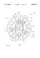
- FIG. 3is a plan view of the sprinkler nozzle of FIG. 2;
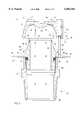
- FIG. 4is an elevational, sectional view taken along the lines IV--IV of FIG. 3;
- FIG. 5is an elevational, sectional view taken along the same section as in FIG. 4, illustrating the sprinkler nozzle in an activated operating configuration
- FIG. 6is a plan view of an alternate embodiment of the sprinkler nozzle according to one aspect of the present invention.
- FIG. 2A sprinkler nozzle or head 20 according to one embodiment of the present invention is depicted in FIG. 2.
- Sprinkler head 20includes a body 22 having a bottom end 24 and a top end 26.
- sprinkler head 20includes a deflector 74 located about body 22, and a fluid flow thrust reverser 34 positioned above deflector 74.
- fire extinguishing fluidflows through body 22, exits and impacts thrust reverser 34.
- the direction of flow of the fluidis reversed by thrust reverser 34 and directed back downwardly toward deflector 74, which is then impacted to distribute the fluid flow in the desired pattern.
- Sprinkler nozzle 20is an upright sprinkler and includes a plurality of external threads 28 adapted in a conventional fashion to mate with internal threads on the top side of a water supply pipe (not shown). Sprinkler nozzle 20 can, of course, be alternately configured with internal threads in order to mate with external threads on a water supply pipe. It will also be noted that, while the description of nozzle 20 is made with reference to using water to extinguish a fire, other fluids besides water can be used with the present invention.
- Body 22 of sprinkler head 20defines a generally cylindrical, vertical channel 30 (FIG. 4). Channel 30 is filled with water or other fire extinguishing fluid and is in fluid communication with the supply pipe.
- a central outlet orifice 32is defined adjacent top end 26 of body 22 (FIGS. 4 and 5).
- Thrust reverser 34When no fire has been detected, central outlet orifice 32 is sealed by a thrust reverser 34.
- Thrust reverser 34includes an exterior surface 36 and an interior surface 38.
- Interior surface 38includes a central, cylindrical protrusion 40 that extends downwardly.
- An annular, doughnut shaped ring 42is disposed around and attached to protrusion 40. Ring or seal 42 seals orifice 32 and prevents water from escaping when no fire is detected.
- Seal 42is made from metal, such as a combination of beryllium and nickel, or any other combination as is known in the art.
- Metal seal 42is covered by a Teflon tape, as is also known in the art. Seal 42 is held tightly against a top edge 44 of body 22 tightly enough to prevent water from escaping by an adjustment plate 60, described below.
- Fusible link 48is made up of a pair of horizontally oriented plates 50a and 50b that are fused together by a temperature sensitive fusing material, such as a low temperature solder. Fusible link 48 is a conventional fusible link and can use any of a variety of known fusing materials. When the ambient temperature of fusible link 48 rises above a certain level, the fusing material melts and destroys the link between horizontal plates 50a and 50b. Horizontal plates 50a and 50b each include an aperture 52 (See FIG. 3) into which a top portion 54 of a pair of arms 56 are inserted.
- Arms 56are tensioned outwardly in a direction 58 shown in FIGS. 3, 4, and 6.
- arms 56pull plates 50a and 50b apart. The separation of plates 50a and b activates the sprinkler nozzle as described below.
- Adjustment plate 60Disposed on the top of exterior surface 36 of thrust reverser 34 is an adjustment plate 60.
- Adjustment plate 60includes a peripheral portion 62 that fits under top portion 54 of arms 56.
- Adjustment plate 60further includes a pair of upturned sides 61 that provide increased structural strength for adjustment plate 60 (see FIGS. 3-6).
- Arms 56secure adjustment plate 60 in position so long as fusible link 48 is not broken. When fusible link 48 is broken, arms 56 pivot outwardly about axes 57 and allow thrust reverser 34 and adjustment plate 60 to be pushed vertically upward by the force of the water. When thrust reverser 34 moves vertically upward, its motion is constrained by pins 46.
- Adjustment plate 60includes a central, threaded aperture 64 into which an adjustment screw 66 is threadably inserted. The bottom of adjustment screws 66 contacts the top of thrust reverser 34 and thereby secures thrust reverser 34 over orifice 32 such that water does not escape from channel 30. By rotating adjustment screws 66 in central, threaded aperture 64, the tightness of thrust reverser 34 against orifice 32 can be adjusted as desired.
- Adjustment screws 66is rotated by a screwdriver, or other suitable means, that fits through a central aperture 68 and fusible link 48. (See FIGS. 3 and 6). Adjustment plate 60 is not secured to any structure after sprinkler nozzle 20 has been activated, and therefore is free to fall off during a fire.
- thrust reverser 34in one embodiment, includes a plurality of vertical pin chambers or bores 47.
- Chambers 47include lower, narrow section 70 having a reduced diameter and an upper, wide section 71 of greater diameter.
- Pins 46include a head 72 having a diameter greater than the diameter of narrow section 70 of chambers 47 yet smaller than the diameter of wide section 71. Pin heads 72 thereby prevent thrust reverser 34 from completely disconnecting itself from pins 46 when it moved upward by the flow of water.
- interior surface 38 of thrust reverser 34is generally hemispherically shaped so as to provide a smoothly curved surface for directing fluid flow. Thrust reverser 34 reverses the flow of water exiting orifice 32 with a minimal decrease in the magnitude of the momentum of the flowing water.
- thrust reverserreverses the water flow approaching about one hundred eighty degrees so that the water flow is back toward sprinkler body 22. The momentum of the water flow is thus reversed.
- An approximate representation of the fluid flow out of nozzle 20is depicted by the arrows in FIG. 5.
- Interior surface 38is shaped to reverse the flow of water so that it flows downwardly.
- Deflector 74comprises a generally flat, annular plate having a plurality of prongs or extensions 76 (FIGS. 3 and 6). Because sprinkler head 20 is an upright sprinkler, top surface 78 of deflector 74 faces the ceiling in whatever room the sprinkler is located. Deflector 74 serves to dispense the water impinging its top surface about the area to be sprinkled.
- Top end 26 of body 22is shaped in a specific manner to ensure that nozzle 20 properly disperses water over the desired area.
- top end 26 of body 22includes a sloping surface 82 that is generally frustoconically shaped. Sloping surface 82 slopes outwardly from top to bottom.
- a straight surface 84is defined immediately below sloping surface 82. The junction 86 of straight surface 84 and sloping surface 82 gives rise to the Coanda effect when the sprinkler is activated and water is flowing. When the water impinges sloping surface 82, it is deflected generally in the direction depicted by arrows 88.
- the flow of water in the direction depicted by arrows 88creates a low pressure area 90 due to the Coanda effect.
- Low pressure area 90therefore diverts some of the flowing water downwardly along straight surface 84.
- the downwardly diverted flow of water along straight surface 84impinges deflector 74 immediately adjacent body 22.
- the downwardly directed flow of water along straight surface 84 due to the Coanda effectensures that the area immediately underneath sprinkler nozzle 20 is sprinkled with adequate water for fire extinguishing.
- FIG. 6A top view of the second embodiment of a sprinkler head 20' according to the present invention is depicted in FIG. 6.
- Nozzle head 20'differs from nozzle 20 in that pins 46' are located between prongs or extensions 76' on deflector 74'. As can be seen in FIG. 3, pins 46 are located above prongs or extensions 76, rather than between them. It is believed that either arrangement provides acceptable sprinkling.
- thrust reverser 34could alternately be fixedly attached to body 22, rather than vertically movable as in the depicted embodiment. Such a modification would require a sealing element disposed between thrust reverser 34 and orifice 32 that would collapse or otherwise be removed upon detection of a fire.
Landscapes
- Health & Medical Sciences (AREA)
- Public Health (AREA)
- Business, Economics & Management (AREA)
- Emergency Management (AREA)
- Fire-Extinguishing By Fire Departments, And Fire-Extinguishing Equipment And Control Thereof (AREA)
Abstract
Description
Claims (28)
Priority Applications (2)
| Application Number | Priority Date | Filing Date | Title |
|---|---|---|---|
| US09/164,702US6082465A (en) | 1998-10-01 | 1998-10-01 | Thrust reverser sprinkler head |
| CA002284429ACA2284429C (en) | 1998-10-01 | 1999-10-01 | Thrust reverser sprinkler head |
Applications Claiming Priority (1)
| Application Number | Priority Date | Filing Date | Title |
|---|---|---|---|
| US09/164,702US6082465A (en) | 1998-10-01 | 1998-10-01 | Thrust reverser sprinkler head |
Publications (1)
| Publication Number | Publication Date |
|---|---|
| US6082465Atrue US6082465A (en) | 2000-07-04 |
Family
ID=22595702
Family Applications (1)
| Application Number | Title | Priority Date | Filing Date |
|---|---|---|---|
| US09/164,702Expired - Fee RelatedUS6082465A (en) | 1998-10-01 | 1998-10-01 | Thrust reverser sprinkler head |
Country Status (2)
| Country | Link |
|---|---|
| US (1) | US6082465A (en) |
| CA (1) | CA2284429C (en) |
Cited By (8)
| Publication number | Priority date | Publication date | Assignee | Title |
|---|---|---|---|---|
| US6554077B2 (en) | 2001-04-12 | 2003-04-29 | The Reliable Automatic Sprinkler Co., Inc. | Quick response adjustable automatic sprinkler arrangements |
| US20040195379A1 (en)* | 2003-03-11 | 2004-10-07 | Trent Rance | Spray nozzle suitable for use in hot corrosive environments and method of use |
| US20080265063A1 (en)* | 2007-04-30 | 2008-10-30 | Johnson Controls Technology Company | Spray nozzle |
| US20120312895A1 (en)* | 2011-06-09 | 2012-12-13 | S.C. Johnson & Son, Inc. | Fluid Dispensing Device for Discharging Fluid Simultaneously in Multiple Directions |
| US9381386B2 (en) | 2006-06-27 | 2016-07-05 | Firebird Sprinkler Company Llc | Fire sprinkler with flue-penetrating non-circular spray pattern |
| US11191985B2 (en) | 2015-12-10 | 2021-12-07 | Marioff Corporation Oy | Water mist nozzle for a fire suppression system |
| US11440032B2 (en) | 2015-06-02 | 2022-09-13 | Tyco Fire Products Lp | Upright fire protection sprinkler |
| EP4171764A4 (en)* | 2020-06-29 | 2024-07-10 | Tyco Fire Products LP | SYSTEMS AND METHODS FOR DEPLOYING THE SPRINKLER DEFLECTOR |
Families Citing this family (1)
| Publication number | Priority date | Publication date | Assignee | Title |
|---|---|---|---|---|
| CN113633917A (en)* | 2021-08-26 | 2021-11-12 | 国星农机装备(新昌)有限公司 | Intelligent fireproof robot |
Citations (15)
| Publication number | Priority date | Publication date | Assignee | Title |
|---|---|---|---|---|
| SU304958A1 (en)* | К. И. Кравченко | SPRINKLER HEAD | ||
| US712693A (en)* | 1902-01-03 | 1902-11-04 | Gaius W Perkins | Sprinkler-head for fire-extinguishers. |
| US1492750A (en)* | 1919-09-18 | 1924-05-06 | Charles L Rogers | Air-distributing means |
| US1715205A (en)* | 1928-06-13 | 1929-05-28 | Frank X Mantsion | Oil burner |
| US2025063A (en)* | 1931-04-14 | 1935-12-24 | Gen Fire Extinguisher Co | Sprinkler |
| US2862565A (en)* | 1957-07-15 | 1958-12-02 | Eugene J Dukes | Automatic sprinkler |
| US3682251A (en)* | 1971-08-20 | 1972-08-08 | Factory Mutual Res Corp | Fire protection system utilizing sprinkler heads with a pressure floor |
| US3958760A (en)* | 1974-10-23 | 1976-05-25 | Peretz Rosenberg | Spray nozzle |
| US4356974A (en)* | 1979-10-24 | 1982-11-02 | Peretz Rosenberg | Spray nozzles |
| US4580729A (en)* | 1985-01-22 | 1986-04-08 | Grinnell Fire Protection Systems Co., Inc. | Sprinkler head with improved spray uniformity |
| US4711399A (en)* | 1983-06-24 | 1987-12-08 | Peretz Rosenberg | Liquid spraying devices |
| US4830118A (en)* | 1987-12-24 | 1989-05-16 | Fire Sprinkler Specialties, Inc. | Shut-off device for a sprinkler assembly |
| US4993496A (en)* | 1987-07-06 | 1991-02-19 | Total Walther Feuerschutz Gmbh | Quick release valve for sprinkler head |
| US5036923A (en)* | 1990-07-30 | 1991-08-06 | U.S. Fire Control Corporation | Fire sprinkler with adjustable deflector |
| US5609211A (en)* | 1991-09-30 | 1997-03-11 | Central Sprinkler Company | Extended coverage automatic ceiling sprinkler |
- 1998
- 1998-10-01USUS09/164,702patent/US6082465A/ennot_activeExpired - Fee Related
- 1999
- 1999-10-01CACA002284429Apatent/CA2284429C/ennot_activeExpired - Fee Related
Patent Citations (15)
| Publication number | Priority date | Publication date | Assignee | Title |
|---|---|---|---|---|
| SU304958A1 (en)* | К. И. Кравченко | SPRINKLER HEAD | ||
| US712693A (en)* | 1902-01-03 | 1902-11-04 | Gaius W Perkins | Sprinkler-head for fire-extinguishers. |
| US1492750A (en)* | 1919-09-18 | 1924-05-06 | Charles L Rogers | Air-distributing means |
| US1715205A (en)* | 1928-06-13 | 1929-05-28 | Frank X Mantsion | Oil burner |
| US2025063A (en)* | 1931-04-14 | 1935-12-24 | Gen Fire Extinguisher Co | Sprinkler |
| US2862565A (en)* | 1957-07-15 | 1958-12-02 | Eugene J Dukes | Automatic sprinkler |
| US3682251A (en)* | 1971-08-20 | 1972-08-08 | Factory Mutual Res Corp | Fire protection system utilizing sprinkler heads with a pressure floor |
| US3958760A (en)* | 1974-10-23 | 1976-05-25 | Peretz Rosenberg | Spray nozzle |
| US4356974A (en)* | 1979-10-24 | 1982-11-02 | Peretz Rosenberg | Spray nozzles |
| US4711399A (en)* | 1983-06-24 | 1987-12-08 | Peretz Rosenberg | Liquid spraying devices |
| US4580729A (en)* | 1985-01-22 | 1986-04-08 | Grinnell Fire Protection Systems Co., Inc. | Sprinkler head with improved spray uniformity |
| US4993496A (en)* | 1987-07-06 | 1991-02-19 | Total Walther Feuerschutz Gmbh | Quick release valve for sprinkler head |
| US4830118A (en)* | 1987-12-24 | 1989-05-16 | Fire Sprinkler Specialties, Inc. | Shut-off device for a sprinkler assembly |
| US5036923A (en)* | 1990-07-30 | 1991-08-06 | U.S. Fire Control Corporation | Fire sprinkler with adjustable deflector |
| US5609211A (en)* | 1991-09-30 | 1997-03-11 | Central Sprinkler Company | Extended coverage automatic ceiling sprinkler |
Non-Patent Citations (2)
| Title |
|---|
| Sarpkaya, T. and Hiriart, G., Finite Elements in Fluids , Chapter 14, Finite Element Analysis of Jet Impingement on Axisymmetric Curved Deflectors, (1975).* |
| Sarpkaya, T. and Hiriart, G., Finite Elements in Fluids, Chapter 14, "Finite Element Analysis of Jet Impingement on Axisymmetric Curved Deflectors," (1975). |
Cited By (11)
| Publication number | Priority date | Publication date | Assignee | Title |
|---|---|---|---|---|
| US6554077B2 (en) | 2001-04-12 | 2003-04-29 | The Reliable Automatic Sprinkler Co., Inc. | Quick response adjustable automatic sprinkler arrangements |
| US20040195379A1 (en)* | 2003-03-11 | 2004-10-07 | Trent Rance | Spray nozzle suitable for use in hot corrosive environments and method of use |
| US6942168B2 (en) | 2003-03-11 | 2005-09-13 | Wafertech, Llc | Spray nozzle suitable for use in hot corrosive environments and method of use |
| US9381386B2 (en) | 2006-06-27 | 2016-07-05 | Firebird Sprinkler Company Llc | Fire sprinkler with flue-penetrating non-circular spray pattern |
| US9675827B2 (en) | 2006-06-27 | 2017-06-13 | Firebird Sprinkler Company Llc | Fire sprinkler with flue-penetrating non-circular spray pattern |
| US20080265063A1 (en)* | 2007-04-30 | 2008-10-30 | Johnson Controls Technology Company | Spray nozzle |
| US20120312895A1 (en)* | 2011-06-09 | 2012-12-13 | S.C. Johnson & Son, Inc. | Fluid Dispensing Device for Discharging Fluid Simultaneously in Multiple Directions |
| US11440032B2 (en) | 2015-06-02 | 2022-09-13 | Tyco Fire Products Lp | Upright fire protection sprinkler |
| US11931751B2 (en) | 2015-06-02 | 2024-03-19 | Tyco Fire Products Lp | Upright fire protection sprinkler |
| US11191985B2 (en) | 2015-12-10 | 2021-12-07 | Marioff Corporation Oy | Water mist nozzle for a fire suppression system |
| EP4171764A4 (en)* | 2020-06-29 | 2024-07-10 | Tyco Fire Products LP | SYSTEMS AND METHODS FOR DEPLOYING THE SPRINKLER DEFLECTOR |
Also Published As
| Publication number | Publication date |
|---|---|
| CA2284429A1 (en) | 2000-04-01 |
| CA2284429C (en) | 2008-04-29 |
Similar Documents
| Publication | Publication Date | Title |
|---|---|---|
| US6367559B1 (en) | Double-blade deflector for side wall sprinkler | |
| CA2668587C (en) | Dual extinguishment fire suppression system using high velocity low pressure emitters | |
| CA2358744C (en) | Vacuum dry sprinkler system containing a sprinkler head with expulsion assembly | |
| EP2012881B1 (en) | Extended coverage horizontal sidewall sprinkler | |
| EP0052935B1 (en) | Nozzle having a deflector for pressurized fire-suppression fluid | |
| US6082465A (en) | Thrust reverser sprinkler head | |
| US4872513A (en) | Chimney fire extinguisher | |
| CA2449036A1 (en) | Sprinkler | |
| WO2022167858A1 (en) | Sprinkler frame support bridge | |
| JPH10108917A (en) | Extinguisher and sprinkler head mounting device therefor | |
| US4436160A (en) | Sprayer | |
| US3871457A (en) | Fluid control device and a fire protection system incorporating said device | |
| JPH074825Y2 (en) | Sprinkler head deflector | |
| US20250090882A1 (en) | Sprinkler frame support bridge | |
| JPH09215769A (en) | Sprinkling method for fixed fire extinguishing equipment and sprinkling nozzle for fire extinguishing | |
| JP3887157B2 (en) | Watering nozzle for fire fighting | |
| JP2852594B2 (en) | Fire extinguishing equipment | |
| JP3734252B2 (en) | Sprinkler fire extinguishing equipment sprinkler nozzle | |
| KR102833943B1 (en) | dry pendent for angle type | |
| KR102810294B1 (en) | Angle type springkler head with variable guide structure | |
| JP2598654B2 (en) | Fire fighting watering head | |
| JP2003284787A (en) | Fire extinguisher | |
| HK1128437B (en) | Extended coverage horizontal sidewall sprinkler |
Legal Events
| Date | Code | Title | Description |
|---|---|---|---|
| AS | Assignment | Owner name:VIKING CORPORATION, MICHIGAN Free format text:ASSIGNMENT OF ASSIGNORS INTEREST;ASSIGNOR:RETZLOFF, JAMES G.;REEL/FRAME:009497/0839 Effective date:19980922 | |
| FPAY | Fee payment | Year of fee payment:4 | |
| FPAY | Fee payment | Year of fee payment:8 | |
| AS | Assignment | Owner name:BANK OF AMERICA, N.A., AS ADMINISTRATIVE AGENT, IL Free format text:NOTICE OF SECURITY INTEREST;ASSIGNOR:THE VIKING CORPORATION;REEL/FRAME:021849/0159 Effective date:20080924 Owner name:BANK OF AMERICA, N.A., AS ADMINISTRATIVE AGENT,ILL Free format text:NOTICE OF SECURITY INTEREST;ASSIGNOR:THE VIKING CORPORATION;REEL/FRAME:021849/0159 Effective date:20080924 | |
| AS | Assignment | Owner name:BANK OF AMERICA, N.A., ILLINOIS Free format text:NOTICE OF RELEASE OF PATENT SECURITY;ASSIGNOR:THE VIKING CORPORATION;REEL/FRAME:023796/0958 Effective date:20091218 Owner name:BANK OF AMERICA, N.A.,ILLINOIS Free format text:NOTICE OF RELEASE OF PATENT SECURITY;ASSIGNOR:THE VIKING CORPORATION;REEL/FRAME:023796/0958 Effective date:20091218 | |
| REMI | Maintenance fee reminder mailed | ||
| LAPS | Lapse for failure to pay maintenance fees | ||
| STCH | Information on status: patent discontinuation | Free format text:PATENT EXPIRED DUE TO NONPAYMENT OF MAINTENANCE FEES UNDER 37 CFR 1.362 | |
| FP | Lapsed due to failure to pay maintenance fee | Effective date:20120704 |