US6081555A - Methods and apparatus for implementing shell mapping techniques in the context of a PCM-based modem communications system - Google Patents
Methods and apparatus for implementing shell mapping techniques in the context of a PCM-based modem communications systemDownload PDFInfo
- Publication number
- US6081555A US6081555AUS08/760,646US76064696AUS6081555AUS 6081555 AUS6081555 AUS 6081555AUS 76064696 AUS76064696 AUS 76064696AUS 6081555 AUS6081555 AUS 6081555A
- Authority
- US
- United States
- Prior art keywords
- ring
- indices
- mapping
- reordering
- signal point
- Prior art date
- Legal status (The legal status is an assumption and is not a legal conclusion. Google has not performed a legal analysis and makes no representation as to the accuracy of the status listed.)
- Expired - Fee Related
Links
- 238000013507mappingMethods0.000titleclaimsabstractdescription92
- 238000000034methodMethods0.000titleclaimsabstractdescription43
- 238000004891communicationMethods0.000titledescription11
- 230000005540biological transmissionEffects0.000claimsabstractdescription23
- 238000000926separation methodMethods0.000claimsabstract4
- 230000006870functionEffects0.000description9
- 238000001228spectrumMethods0.000description9
- 238000005516engineering processMethods0.000description6
- 238000010586diagramMethods0.000description3
- 230000000694effectsEffects0.000description3
- 230000003466anti-cipated effectEffects0.000description2
- 230000006735deficitEffects0.000description2
- 238000011161developmentMethods0.000description2
- SYHGEUNFJIGTRX-UHFFFAOYSA-NmethylenedioxypyrovaleroneChemical groupC=1C=C2OCOC2=CC=1C(=O)C(CCC)N1CCCC1SYHGEUNFJIGTRX-UHFFFAOYSA-N0.000description2
- 238000012986modificationMethods0.000description2
- 230000004048modificationEffects0.000description2
- 238000007493shaping processMethods0.000description2
- RYGMFSIKBFXOCR-UHFFFAOYSA-NCopperChemical compound[Cu]RYGMFSIKBFXOCR-UHFFFAOYSA-N0.000description1
- 101100386054Saccharomyces cerevisiae (strain ATCC 204508 / S288c) CYS3 geneProteins0.000description1
- 239000006227byproductSubstances0.000description1
- 230000001010compromised effectEffects0.000description1
- 238000012937correctionMethods0.000description1
- 230000003247decreasing effectEffects0.000description1
- 238000013461designMethods0.000description1
- 230000008030eliminationEffects0.000description1
- 238000003379elimination reactionMethods0.000description1
- 230000001771impaired effectEffects0.000description1
- 238000007689inspectionMethods0.000description1
- 238000012804iterative processMethods0.000description1
- 238000013139quantizationMethods0.000description1
- 238000011160researchMethods0.000description1
- 238000005070samplingMethods0.000description1
- 101150035983str1 geneProteins0.000description1
- 230000001360synchronised effectEffects0.000description1
Images


Classifications
- H—ELECTRICITY
- H04—ELECTRIC COMMUNICATION TECHNIQUE
- H04L—TRANSMISSION OF DIGITAL INFORMATION, e.g. TELEGRAPHIC COMMUNICATION
- H04L25/00—Baseband systems
- H04L25/38—Synchronous or start-stop systems, e.g. for Baudot code
- H04L25/40—Transmitting circuits; Receiving circuits
- H04L25/49—Transmitting circuits; Receiving circuits using code conversion at the transmitter; using predistortion; using insertion of idle bits for obtaining a desired frequency spectrum; using three or more amplitude levels ; Baseband coding techniques specific to data transmission systems
- H04L25/4917—Transmitting circuits; Receiving circuits using code conversion at the transmitter; using predistortion; using insertion of idle bits for obtaining a desired frequency spectrum; using three or more amplitude levels ; Baseband coding techniques specific to data transmission systems using multilevel codes
- H04L25/4927—Transmitting circuits; Receiving circuits using code conversion at the transmitter; using predistortion; using insertion of idle bits for obtaining a desired frequency spectrum; using three or more amplitude levels ; Baseband coding techniques specific to data transmission systems using multilevel codes using levels matched to the quantisation levels of the channel
Definitions
- the present inventionrelates, generally, to a technique for adapting standard V.34 shell mapping algorithms for use in conjunction with PCM-based modems and, more particularly, to a technique for reordering ring indices generated by the shell mapping algorithm to yield an optimum balance between transmit power and frequency of use of constellation rings having low interval values between constellation points.
- the present inventionrelates to signed point encoders used in the transmission of digital information over an analog medium connected to a digital network, particularly in the context of Pulse Code Modulation (PCM) modems.
- PCMPulse Code Modulation
- PCM modemsThere has been much recent development of high-speed communications technology based on PCM modems, where data rates of at least 56 Kbps are said to be actually attainable.
- the PCM modem technologyis based on the simple realization that the PSTN is increasingly a digital network and not an analog network. Also, more and more central site modems are connected to the PSTN through digital connections, i.e., T1 in the U.S. and E1in Europe, without requiring a CODEC (coder/decoder).
- a CODECis a device which connects the digital portion of the network to the analog local loop and converts between analog and digital.
- central site modemsrefer to those modems installed at an ISP, or at a corporation, for example, to allow many simultaneous connections for remote local area network (LAN) access.
- the recent 56 Kbps technologyseeks to address an impaired section of the communications path of the PSTN digital network, where the impairment is due to the hybrid and the copper wire interface between the telephone central office and the user's home, usually referred to as the analog local loop.
- PCM modemsSince recently, much has been described about PCM modems and how they can and should facilitate downstream data communication at a much higher rate than the present paradigm.
- PCM modemhas been the subject of a recent Telecommunications Industry Association (TIA) Technical Committee TR-30 Standards meeting on Oct. 16-17, 1996.
- TAATelecommunications Industry Association
- the submitted technical contributionsinclude Guozhu Long's DC Suppressor for 56K Modems, Guozhu Long's Two-Step Mappingfor 56K Modems, David C.
- U.S. Pat. No. 5,528,625issued to Ender Ayanoglu of AT&T, dated Jun. 18, 1996, entitled High Speed Quantization-Level-Sampling Modem With Equalization Arrangement, discloses a QLS modem for high-speed data communication.
- Another U.S. patent also issued to Ender Ayanoglu of AT&T, U.S. Pat. No. 5,394,437, dated Feb. 28, 1995 entitled High-Speed Modem Synchronized To A Remote CODECdiscloses a high-speed modem for data transmission over an analog medium in tandem with a digital network.
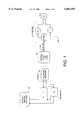
- FIG. 1depicts a conceptual diagram of the typical high-speed communication path using PCM modem technology.
- An ISP, or central site, 100is digitally connected to a telephone network 130 through its transmitter 110 and receiver 120.
- the network 130is connected to a local loop 150 through a central office line card 140.
- the line cardtypically has a PCM CODEC implemented therein.
- the local loop 150is connected to the user's PC at the user's site through the user's modem 160.
- the connection between the ISP modem transmitter 110 to the telephone network 130is a digital connection with a typical data rate of about 64 Kbps.
- the central site transmitter 110needs to transmit the digital data in a particular way to fully exploit its digital connection to the network.
- ⁇ -law constellations, shell mapping, and PCM-based modem systems in this new paradigmhas some obstacles.
- the shell mapping algorithmis essentially designed to select ring indices in a manner which minimizes average transmission power based on, inter alia, the assumption that the average power of each ring is approximately proportional to its ring index, and based on the further assumption that any particular constellation can be scaled to meet the transmit power level requirement.
- the signal pointsare selected from a fixed, non-uniformly spaced set of levels determined by the PCM codec in accordance with the well-known ⁇ -law algorithm.
- the coding componentoften involves error-correction coding, whereas the mapping component strives to minimize the transmission power in view of the restraints imposed by the coding process.
- the traditional V.34 coding functioninvolves the use of convolutional trellis codes, whereas the mapping is in the form of shell mapping.
- the shell mapping algorithm employed in V.34is one of the more complex functions in a V.34 modem.
- the V.34 encoding algorithmtakes a block of bits corresponding to a mapping frame of eight (8) symbols, and maps a part of that block to a set of eight (8) ring indices, which are used to determine a subset of the constellation from which the transmitted signal points are selected.
- the subsetsare, as the name indicates, in the form of concentric rings around the origin.
- the energy of the signal points in a given ringis within a certain range, which energy range increases with increasing distance from the origin.
- the index of the ringis a fairly accurate approximation of the contribution to signal power of a point in that ring.
- the V.34 shell mapping algorithmuses this simple relationship to select sets of ring indices where the sum of the indices is the smallest. Sets of ring indices with higher sums tend to be omitted, thus optimizing transmit power.
- the innermost ringsare selected most often, and the outermost rings are selected least often.
- the signal pointsare selected from a non-uniform set of levels determined by the ⁇ -law algorithm. Many of the characteristics of the V.34 constellation are therefore lost in a PCM modem context, for example the linear relationship between ring index and that ring's contribution to transmission power.
- the present inventionprovides methods and apparatus for implementing a V.34-type shell mapping algorithm in the context of a PCM modem.
- a signal point encoding techniqueis proposed which effectively utilizes many of the advantageous aspects of the V.34 shell mapping algorithm, while modifying other V.34-type signal point encoding practices to allow the efficient use of shell mapping techniques in a PCM-based modem context.
- a V.34-type shell mapping techniqueis employed which generates ring indices generally in accordance with known principles.
- ring indicesare then applied to a reordering module, for example a look up table, dynamic algorithm, or the like, such that the "ring" indices produced by the shell mapping algorithm are reordered.
- a reordering modulefor example a look up table, dynamic algorithm, or the like, such that the "ring" indices produced by the shell mapping algorithm are reordered.
- This reorderingpermits the signal point encoder of the present invention to take advantage of the non-uniform probability distribution provided by the shell mapping algorithm.
- the ringsare reordered in such a way as to assign the sets of constellation points with smallest minimum distances to the rings with the lowest frequency of occurrence, and the sets of points with higher minimum distances (but lower power) to the rings associated with the higher frequency of occurrence.
- a signal point encoding schemeis proposed which results in an average transmission power that is substantially equal for most data rates employed in contemporary modems.
- the subject signal point encoding schemeelegantly accommodates fractional bits per symbol.
- FIG. 1depicts a conceptual diagram of a high-speed communication path using PCM modem technology
- FIG. 2is a block diagram of the shell mapping, reordering, and signal point constellation look up table components of an exemplary signal point encoder in accordance with the present invention
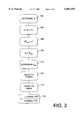
- FIGS. 3-5are flow charts describing an algorithm useful in the context of the present invention for generating signal point constellations for various data rates and reordering architectures for reordering ring indices in accordance with preferred embodiments of the present invention.
- FIG. 6is a flow chart describing an alternative to reordering methodology for optimizing transmission power in the context of the subject signal point encoder.
- a look up table used to reorder the shell mapping indicesis constructed in a manner calculated to allow optimum use of those ring indices having signal points spaced apart by d min , while maintaining average transmission power within desired limits (e.g., the -12 dBm limit imposed by the FCC.
- optimum ring reordering tablesare arrived at through an iterative process which incrementally shifts the rings containing signal points separated by d min to progressively lower assignments (in terms of frequency of occurrence), until acceptable average power ranges are satisfied.
- d minprogressively lower assignments
- acceptable average power rangesare satisfied.
- an exemplary PCM-based modem transmitter 110suitably comprises a signal point encoder 202.
- signal point encoder 202comprises a shell mapper 204, a reordering look up table 206, a mapping block 208, a spectrum control circuit 210, and a polarity block 212.
- shell mapper 204reordering look up table 206
- mapping block 208a mapping block 208
- spectrum control circuit 210e.g., polarity block 212
- spectrum control 210may suitably be implemented as one or a combination of discrete electronic components, integrated circuits, software modules, or any other convenient implementation.
- mapping framemay be illustrated as follows:
- the actual data to be transmitted by the modem through the PSTN to the receiving modemmay be formatted and transmitted via any convenient methodology, for example as described in ITU Standard V.42, incorporated herein by this reference.
- an exemplary mapping frame useful in conjunction with the present inventioncomprises eight (8) PCM samples per mapping frame, corresponding to a total of b bits.
- the first K bits of a mapping framemay be conveniently used for the shell mapper (with a 0 inserted for low mapping frames), and the following b-K bits are suitably divided in eight (8) equal parts with u bits in each part depending on such factors as data rate, redundancy level, and the like.
- a redundancy value of 16means that in one out of every sixteen (16) samples, one bit is used for redundancy purposes.
- a separate reordering look up table and a separate signal point constellationwill be derived for each anticipated data rate R.
- the ring reordering look up tables and signal point constellation tableswill be set forth for data rates of 56 Kbps, 52 Kbps, 48 Kbps, 44 Kbps, 40 Kbps, 36 Kbps, and 32 Kbps. It will be appreciated, however that the methodologies and techniques described herein may suitably be applied to virtually any desired data transmission rate.
- a value of Kmay be determined (step 302) by first determining a value of b.
- bR/1000+r/8, where r is defined as the redundancy factor.
- ris defined as the redundancy factor.
- the value of Kmay then be determined from b by subtracting eight from b an integer number (u) of times until K has an integer value of between 24 and 31, inclusive (i.e., 24 ⁇ K ⁇ 31) (step 304).
- the systemdetermines the minimum number of rings (M min ) such that M 8 min is greater than or equal to 2 K (step 306). Indeed, once K is determined, the value of M min will necessarily be an unambiguous integer.
- the systemthen chooses an appropriate constellation expansion factor to yield the actual number of rings M, which may be greater than or equal to M min (step 308). In this regard, if M 8 min is approximately equal to 2 k (i.e., the rings have approximately equal output probabilities), it may be desirable to increase M by one or two to thereby vary the probability associated with the various ring indices.
- Mmay be increased by one or two, or even more, although it is generally desirable to increase M by one to keep overall power within reasonable limits. Furthermore, increasing M increases the signal's peak-to-mean ratio, which thereby increases the effect of nonlinear distortion.
- a tentative minimum distance d minis suitably selected such that b 1/8 points can be selected from the set of ⁇ -law levels. That is, when calculating b 1/8 , the value should be rounded upward to the next integer value; it is this integer value number of points that is minimally required to convey the number of bits b. If the average energy of the set of points of that number is close to the corresponding transmit power limitation, then the d min can be considered suitable.
- the systemdetermines a set A of M*2 u constellation points from the ⁇ -law set with minimum distance d min and minimum energy (step 312). At this time, it is known how many total points are in the signal constellation for a particular data rate, and it is also known that each ring contains the same number of signal points. It is further known that 2 u signal points are associated with each ring. Thus, the first point selected would be the smallest signal level in the ⁇ -law set greater than or equal to d min /2. The second point would be the smallest signal level in the ⁇ -law set greater than or equal to the sum of the first point and d min . Continuing in this fashion, the n-th point would be selected as the smallest signal level in the ⁇ -law set greater than or equal to the sum of point n-1 and d min .
- a subset of rings (B)is then selected from the set of points A (step 314). More particularly, a set of rings B is selected which includes points with distance d min to adjacent points such that B has a value of between 1 and M, inclusive (i.e., 1 ⁇ B ⁇ M). In step 314, it is also desirable to determine the number of "distances" which are in each of the rings which comprise B.
- the second point in the first ring (18)has two adjacent points (6 and 30) from which it is separated by d min .
- the third point in the first ring (30)has only one adjacent point (18) from which it is separated by d min , and so on.
- the first ringhas at least one point which is separated from an adjacent point by d min , and thus is included in the set of rings B.
- the first ringhas a total "count" of 13, indicating that the first ring comprises 13 such "distances”.
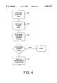
- the systemnext determines the average energy of each of the rings in the constellation (step 316).
- the average energy for each ringmay be conveniently computed for each ring by summing the squares of all the signal point values in the ring, and dividing the sum by the number of points in the ring.
- the systemdetermines an initial reordering of the ring values.
- the systemdetermines the average transmit power given the current assignment (step 406). More particularly, the system suitably runs an appropriate shell mapper algorithm (e.g., the V.34 shell mapper algorithm) for random inputs to obtain an average probability (or output frequency) associated with each ring level. For each ring level, the average probability multiplied by the average ring energy (previously calculated in step 316, yields a fairly accurate indication of the average contribution to the transmit power of each ring level.
- an appropriate shell mapper algorithme.g., the V.34 shell mapper algorithm
- the systemcan determine if the then current ring assignment produces a reordering of ring indices which yields acceptable power levels, i.e., the system determines whether the current reordered ring assignments allows the signal point encoder to operate within an acceptable power transmission range. If power transmission levels are acceptable ("yes" branch from step 408), the reordering algorithm may be completed, with the current reordering configuration suitably encoded into read only memory or other appropriate medium associated with reorder look up table 206 (see FIG. 2). Alternatively, if acceptable transmit power is determined at step 408, the system may also suitably reevaluate d min to check if a value of d min has been selected which is too small for optimum performance.
- step 410If the transmit power in view of the current ring assignments is still unacceptably high ("no" branch from step 408), the system is instructed to perform the following interchange algorithm to manipulate the reordered ring assignments to achieve acceptable transmit power levels (step 410). In this regard, it is desirable to reevaluate the transmit power associated with the then current assignments after each interchange; if after a single interchange the overall transmit power is acceptable, the system suitably concludes that an appropriate ring index reordering configuration has been established, and the then current reordering table may be written into index reorder look up table 206.
- a thresholda power level other than that dictated by the FCC or the PSTN (currently -12 dBm.
- a power levelother than that dictated by the FCC or the PSTN (currently -12 dBm.
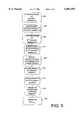
- the ring not in B having the highest energyis "shifted" to the index immediately above the ring in B having the lowest number of d min distance and the rings are suitably re-indexed (step 502).
- This shiftingmay be visualized as downward movement of the ring in, e.g., Table 3.
- the overall transmit power of the reorder tableshould be reevaluated to determine if it is acceptable; if transmit power is acceptable, a satisfactory reorder look up table has been established. If transmit power is still unacceptable, then continued shifting should be undertaken.
- the ring not in B having the highest energyis then shifted to the index immediately above the ring having the second lowest number of d min distances (step 504), and so on. More particularly and with reference to step 505 and the above Initial Reorder Table (Table 3), the interchange process continues iteratively down the table, with the net effect that the original ring corresponding to points not in B with highest energy is sequentially moved down the table until it is assigned to the highest reorder index (i.e., it may eventually be shifted to the index immediately above the ring in B having the highest d min count).
- the ring corresponding to the set of points not in B having the second highest energyis suitably the ring in B having the lowest number of d min distances (step 506). If necessary shifted to the index immediately above the ring not in B with the second highest energy (just interchanged in step 506) is then shifted to the index immediately above the ring in B with the second lowest number of d min distances, and so on (step 508) until the ring not in B with the second highest energy is sequentially shifted to the index immediately above the ring in B having the highest d min count (of course, the overall transmit power should be evaluated after each interchange, as discussed above). The above interchanges are then sequentially repeated (step 509) for the ring not in B with the third highest energy, the fourth highest energy, and so on. If an acceptable transmit power has not been reached following step 509, the ordering will have become as follows in Table 5:
- the systemnow interchanges among the rings in B starting with the ring in B with the highest energy, shifting it to the index immediately above the ring in B with the next highest ring assignment (step 510). If necessary, this ring is iteratively shifted through the next highest ring assignments until the ring in B with the highest energy has the highest ring index of the sets of rings in B (step 511).
- the ring in B with the highest energygenerally corresponds to the rings with the fewer minimum distances, this may not necessarily be true in all instances.
- the systemshifts the ring in B with the second highest energy to the index immediately above with the ring in B having the next higher ring assignment, and thereafter with the ring in B having the next higher ring assignment, and so on, until the ring in B with the second highest energy has the second highest ring index of the rings in B (step 512).
- the ring in B with the third highest energyis shifted to the index immediately above the ring in B having the next highest ring index, and thereafter the ring in B with the third highest energy is shifted to the index immediately above the ring in B having the next higher ring assignment, and so on until all the sets of points (rings) in B are ordered by increasing average energy (step 514).
- the PCM constellation ringsare suitably ordered in increasing transmit power, thus providing a ring index reordering table which yields the lowest overall transmit power, since the ring indices are ordered in decreasing rate of occurrence. No other assignment within the model should yield a lower transmit power. Thus, if unacceptable power transmit levels have not yet been achieved, it may be desirable to modify either M or d min (step 516).
- an increase in Mis acceptable, it may be desirable to increase M by 1 (or even by 2), as long as increasing M results in an index reorder table which yields acceptable power transmit values.
- step 516will lead to a lower transmit power in the next sequence of interchanges until the desired power level is reached.
- an exhaustive search through all possible assignmentswould also reveal an optimum assignment, in lieu of the steps outlined in FIGS. 3-5. However, it is believed that such an exhaustive search would not yield an appreciably better result than the above algorithm.
- ring index reordering tablesmay be written into reorder table 206 in any convenient manner.
- the following tablesets forth the values for b, r, K, M, the points/ring, and L for various data rates ranging from 56 Kbps to 32 Kbps:
- rthe redundancy, where, in every r-th sample, the sign bit is utilized for spectrum control.
- Kthe number of input bits to the shell mapper.
- Mthe number of rings utilized in shell mapping for the particular data rate.
- points/ringthe number of points in each ring, i.e., 2 u .
- Lrepresents only the number of positive values set forth in the signal constellation for each data rate, it being understood that an equal number of mirror image negative values are also included in the constellation for each data rate, with the positive and negative signal points within each constellation being symmetric about the zero axis.
- the output of reorder table 206suitably embodies the reordered ring indices, which are reordered in accordance with the above reordering configurations.
- the reordered ring indices output from module 206are suitably applied to a multiplier 216, which advantageously shifts the ring indices to the left by a desired number of bits, as is known in the art.
- the left-shifted, reordered ring indicesare then summed with the mapping values (Q j ,1, Q j ,2, . . . , Q j ,u-1) at summer 214.
- the output of summer 214, the signal point indexis suitably applied to mapping module 208, wherein the appropriate signal values are selected. Given a table of signal points as in Table 2, the signal point index represents an index directly determining which signal point is selected from the table.
- mapping module 208suitably comprises a unique, predetermined signal constellation for each anticipated data rate.
- exemplary signal constellations for various data rateswhich are suitably encoded within mapping module 208, are as follows:
- mapping module 208Once the signal point indices values are mapped to the signal constellation points in mapping module 208, the output from module 208 is suitably applied to a multiplier 218, whereupon a polarity bit from polarity module 212 is combined with the output of mapping module 208 to ensure that the encoded signal output from multiplier 218 includes the appropriate polarity.
- Spectrum control unit 210suitably controls the spectrum of the transmitted PCM signal by modifying the sign of every r-th sample based on an objective function of C n , where: ##EQU1##
- the metric C nis calculated for each output sample x n , and the sign of every r-th sample is determined by considering C n . If C n is negative, the bit Q j ,0 is set to 0 and the outgoing sample is thus positive. If C n is positive or 0, Q j ,0 is set to 1 and the outgoing sample becomes negative.
- a redundant-sign algorithmis used for spectrum control.
- initial parameters such as M, d min , A, and bare determined as set forth in steps 302-316 (step 602).
- the systemthen assigns ring indices to sets of rings as a function of increasing average energy (step 604); that is, the ring indices which are generated by shell mapper 204 are used essentially as they are output from shell mapper 204, without reordering.
- the systemdetermines the average transmit power given the current assignment (step 606).
- the systemdetermines which ring R' has the highest number of d min distances (step 610).
- the systemreassigns points in rings above R', using a distance of d min (except for the first point above R', which is at a distance d' from the highest point in R'). Thus, R' is effectively removed from the set B.
- step 610is repeated with a different ring. Steps 606 and 610 are repeated until the resulting transmit power becomes too high. Then, the last signal point assignment that resulted in an acceptable transmit power level is selected (step 612).
- the present inventionprovides methods and apparatus for implementing a V.34-type shell mapping algorithm in the context of a PCM modem.
- the proposed signal point encoding schemeresults in an average transmission power that is substantially equal for most data rates employed in contemporary modems.
- the subject signal point encoding schemeelegantly accommodates fractional bits per symbol.
Landscapes
- Physics & Mathematics (AREA)
- Spectroscopy & Molecular Physics (AREA)
- Engineering & Computer Science (AREA)
- Computer Networks & Wireless Communication (AREA)
- Signal Processing (AREA)
- Digital Transmission Methods That Use Modulated Carrier Waves (AREA)
- Dc Digital Transmission (AREA)
- Error Detection And Correction (AREA)
Abstract
Description
TABLE 1 __________________________________________________________________________Allocation of bits in a mapping frame. __________________________________________________________________________ ##STR1## __________________________________________________________________________
TABLE 2 ______________________________________ 56 Kbps Constellation ______________________________________ 6, 18, 30, 45, 57, 69, 81, 93 107, 123, 139, 155, 171, 187, 203, 219 231, 247, 263, 279, 295, 311, 327, 343 359, 375, 391, 407, 423, 439, 455, 471 495, 527, 559, 591, 623, 655, 687, 719 751, 783, 815, 847, 879, 911, 943, 975 1023, 1087, 1151, 1215, 1279, 1343, 1407, 1471 1535, 1599, 1663, 1727, 1791, 1855, 1919, 1983 2079, 2207, 2335, 2463, 2591, 2719, 2847, 2975 ______________________________________
TABLE 3 ______________________________________ Initial Reorder Table Reorder Index PCM-constellation point ring ______________________________________ 0 Ring not in B withlowest energy 1 Ring not in B with 2nd lowest energy . . . Ring not in B with highest energy, Ring in B with lowest number of d.sub.min distances Ring in B with 2nd lowest number of d.sub.min distances . . . M-1 Ring in B with highest number of d.sub.min distances ______________________________________
TABLE 4 ______________________________________ First Revised Reorder Table Reorder Index PCM-constellation point ring ______________________________________ 0 Ring not in B withlowest energy 1 Ring not in B with 2nd lowest energy . . . Ring not in B with 2nd highest energy Ring in B with lowest number of d.sub.min distances Ring in B with 2nd lowest number of d.sub.min distances . . . M-2 Ring in B with highest number of d.sub.min distances M-1 Ring not in B with highest energy ______________________________________
TABLE 5 ______________________________________ Second Revised Reorder Table Reorder Index PCM-constellation point ring ______________________________________ 0 Ring in B with lowest number of d.sub.min distances 1 Ring in B with 2nd-lowest number of d.sub.min distances . . . Ring in B with highest number of d.sub.min distances Ring not in B with lowest energy Ring not in B with 2nd-lowest energy . . . M-2 Ring not in B with 2nd-highest energy M-1 Ring not in B with highest energy ______________________________________
TABLE 6 ______________________________________ Points/ Data Rate, R b r K M ring L ______________________________________ 56 000 57 16 25 9 2 × 8 72 52 000 53 16 29 14 2 × 4 56 48 000 50 4 26 11 2 × 2 44 44 000 46 4 30 16 2 × 2 32 40 000 44 2 28 12 2 × 2 24 36 000 40 2 24 9 2 × 2 18 32 000 36 2 28 14 2 × 1 14 ______________________________________
______________________________________ Ring order for 56 Kbps: 3, 4, 2, 5, 1, 0, 6, 7, 8 (i.e., f(0) = 3, f(1) = 4, . . . ) Ring order for 52 Kbps: 3, 5, 6, 7, 8, 4, 2, 9, 1, 0, 10, 11, 12, 13 Ring order for 48 Kbps: 8, 9, 7, 6, 5, 4, 3, 2, 1, 10, 0 Ring order for 44 Kbps: 7, 8, 2, 3, 4, 5, 6, 0, 1, 9, 10, 11, 12, 13, 14, 15 Ring order for 40 Kbps: 4, 5, 2, 3, 0, 1, 6, 7, 8, 9, 10, 11 Ring order for 36 Kbps: 0, 1, 2, 7, 5, 4, 6, 3, 8 Ring order for 32 Kbps: 0, 1, 2, 3, 4, 5, 6, 7, 8, 9, 10, 11, 12, 13 ______________________________________
______________________________________ Signal constellation for 56 Kbps (minimum distance 12, 72 points) 6, 18, 30, 45, 57, 69, 81, 93 107, 123, 139, 155, 171, 187, 203, 219 231, 247, 263, 279, 295, 311, 327, 343 359, 375, 391, 407, 423, 439, 455, 471 495, 527, 559, 591, 623, 655, 687, 719 751, 783, 815, 847, 879, 911, 943, 975 1023, 1087, 1151, 1215, 1279, 1343, 1407, 1471 1535, 1599, 1663, 1727, 1791, 1855, 1919, 1983 2079, 2207, 2335, 2463, 2591, 2719, 2847, 2975 Signal constellation for 52 Kbps (minimum distance 24, 56 points): 12, 37, 61, 85 115, 139, 163, 187 211, 247, 279, 311 343, 375, 407, 439 471, 495, 527, 559 591, 623, 655, 687 719, 751, 783, 815 847, 879, 911, 943 975, 1023, 1087, 1151 1215, 1279, 1343, 1407 1471, 1535, 1599, 1663 1727, 1791, 1855, 1919 1983, 2079, 2207, 2335 2463, 2591, 2719, 2847 Signal constellation for 48 Kbps (minimum distance 33, 44 points) 16, 49, 81, 115 147, 179, 211, 247 279, 311, 343, 375 407, 439, 471, 527 559, 591, 623, 655 687, 719, 751, 783 815, 847, 879, 911 943, 975, 1023, 1087 1151, 1215, 1279, 1343 1407, 1471, 1535, 1599 1663, 1727, 1791, 1855 Signal constellation for 44 Kbps (minimum distance 64, 32 points) 33, 99 163, 231 295, 359 423, 495 559, 623 687, 751 815, 879 943, 1023 1087, 1151 1215, 1279 1343, 1407 1471, 1535 1599, 1663 1727, 1791 1855, 1919 1983, 2079 Signal constellation for 40 Kbps (minimum distance 64, 24 points) 37, 115 187, 263 343, 423 495, 591 687, 783 879, 975 1087, 1151 1215, 1279 1343, 1407 1471, 1535 1599, 1663 1727, 1791 Signal constellation for 36 Kbps (minimum distance 96, 18 points) 49, 147 247, 343 439, 559 655, 751 847, 943 1087, 1215 1343, 1471 1599, 1727 1855, 1983 Signal constellation for 32 Kbps (minimum distance 128, 14 points) 81 247 407 591 751 911 1087 1279 1471 1599 1727 1855 1983 2207 ______________________________________
Claims (35)
______________________________________ 0 6, 18, 30, 45, 57, 69, 81, 93 1 107, 123, 139, 155, 171, 187, 203, 219 2 231, 247, 263, 279, 295, 311, 327, 343 3 359, 375, 391, 407, 423, 439, 455, 471 4 495, 527, 559, 591, 623, 655, 687, 719 5 751, 783, 815, 847, 879, 911, 943, 975 6 1023, 1087, 1151, 1215, 1279, 1343, 1407, 1471 7 1535, 1599, 1663, 1727, 1791, 1855, 1919, 1983 8 2079, 2207, 2335, 2463, 2591, 2719, 2847, 2975 ______________________________________
______________________________________ 0 12, 37, 61, 85 1 115, 139, 163, 187 2 211, 247, 279, 311 3 343, 375, 407, 439 4 471, 495, 527, 559 5 591, 623, 655, 687 6 719, 751, 783, 815 7 847, 879, 911, 943 8 975, 1023, 1087, 1151 9 1215, 1279, 1343, 1407 10 1471, 1535, 1599, 1663 11 1727, 1791, 1855, 1919 12 1983, 2079, 2207, 2335 13 2463, 2591, 2719, 2847 ______________________________________
______________________________________ 0 16, 49, 81, 115 1 147, 179, 211, 247 2 279, 311, 343, 375 3 407, 439, 471, 527 4 559, 591, 623, 655 5 687, 719, 751, 783 6 815, 847, 879, 911 7 943, 975, 1023, 1087 8 1151, 1215, 1279, 1343 9 1407, 1471, 1535, 1599 10 1663, 1727, 1791, 1855 ______________________________________
______________________________________ 0 33, 99 1 163, 231 2 295, 359 3 423, 495 4 559, 623 5 687, 751 6 815, 879 7 943, 1023 8 1087, 1151 9 1215, 1279 10 1343, 1407 11 1471, 1535 12 1599, 1663 13 1727, 1791 14 1855, 1919 15 1983, 2079 ______________________________________
______________________________________ 0 37, 115 1 187, 263 2 343, 423 3 495, 591 4 687, 783 5 879, 975 6 1087, 1151 7 1215, 1279 8 1343, 1407 9 1471, 1535 10 1599, 1663 11 1727, 1791 ______________________________________
______________________________________ 0 49, 147 1 247, 343 2 439, 559 3 655, 751 4 847, 943 5 1087, 1215 6 1343, 1471 7 1599, 1727 8 1855, 1983 ______________________________________
Priority Applications (5)
| Application Number | Priority Date | Filing Date | Title |
|---|---|---|---|
| US08/760,646US6081555A (en) | 1996-12-04 | 1996-12-04 | Methods and apparatus for implementing shell mapping techniques in the context of a PCM-based modem communications system |
| US08/972,960US6259742B1 (en) | 1996-12-04 | 1997-11-19 | Methods and apparatus for optimizing shell mapping techniques using an approximated power cost function |
| JP9334237AJPH10200593A (en) | 1996-12-04 | 1997-12-04 | Signal point encoder, encoding method, method for resequencing ring index and method for selecting ring index |
| EP97121321AEP0852438A3 (en) | 1996-12-04 | 1997-12-04 | Trellis shaping for multilevel transmission, with levels matched to network quantisation |
| US09/394,957US6226334B1 (en) | 1996-12-04 | 1999-09-10 | Methods and apparatus for implementing shell mapping techniques in the context of a PCM-based modem communication system |
Applications Claiming Priority (1)
| Application Number | Priority Date | Filing Date | Title |
|---|---|---|---|
| US08/760,646US6081555A (en) | 1996-12-04 | 1996-12-04 | Methods and apparatus for implementing shell mapping techniques in the context of a PCM-based modem communications system |
Related Child Applications (2)
| Application Number | Title | Priority Date | Filing Date |
|---|---|---|---|
| US08/972,960Continuation-In-PartUS6259742B1 (en) | 1996-12-04 | 1997-11-19 | Methods and apparatus for optimizing shell mapping techniques using an approximated power cost function |
| US09/394,957ContinuationUS6226334B1 (en) | 1996-12-04 | 1999-09-10 | Methods and apparatus for implementing shell mapping techniques in the context of a PCM-based modem communication system |
Publications (1)
| Publication Number | Publication Date |
|---|---|
| US6081555Atrue US6081555A (en) | 2000-06-27 |
Family
ID=25059744
Family Applications (2)
| Application Number | Title | Priority Date | Filing Date |
|---|---|---|---|
| US08/760,646Expired - Fee RelatedUS6081555A (en) | 1996-12-04 | 1996-12-04 | Methods and apparatus for implementing shell mapping techniques in the context of a PCM-based modem communications system |
| US09/394,957Expired - Fee RelatedUS6226334B1 (en) | 1996-12-04 | 1999-09-10 | Methods and apparatus for implementing shell mapping techniques in the context of a PCM-based modem communication system |
Family Applications After (1)
| Application Number | Title | Priority Date | Filing Date |
|---|---|---|---|
| US09/394,957Expired - Fee RelatedUS6226334B1 (en) | 1996-12-04 | 1999-09-10 | Methods and apparatus for implementing shell mapping techniques in the context of a PCM-based modem communication system |
Country Status (3)
| Country | Link |
|---|---|
| US (2) | US6081555A (en) |
| EP (1) | EP0852438A3 (en) |
| JP (1) | JPH10200593A (en) |
Cited By (13)
| Publication number | Priority date | Publication date | Assignee | Title |
|---|---|---|---|---|
| US6229886B1 (en)* | 1997-01-22 | 2001-05-08 | Ciena Corporation | Method and apparatus for providing 56K modem technology for public switched telephone networks |
| US6516025B1 (en)* | 1999-04-29 | 2003-02-04 | Texas Instruments Incorporated | High-speed upstream modem communication |
| US6553063B1 (en)* | 1998-10-30 | 2003-04-22 | Broadcom Corporation | Constellation-multiplexed transmitter and receiver |
| US6553535B1 (en)* | 1998-08-21 | 2003-04-22 | Massachusetts Institute Of Technology | Power-efficient communication protocol |
| US20030115533A1 (en)* | 1998-08-21 | 2003-06-19 | Asada Haruhiko H. | Source coding for interference reduction |
| US6611554B1 (en)* | 1998-10-13 | 2003-08-26 | Koninklijke Philips Electronics N.V. | Method of forming a set of constellations which is intended to be used for transmitting data between a transmitter and a receiver |
| US20030206578A1 (en)* | 2000-06-20 | 2003-11-06 | Betts William L. | Systems and methods for fractional bit rate encoding in a pulse amplitude modulation communication system |
| US20040240577A1 (en)* | 2003-05-30 | 2004-12-02 | Nokia Corporation | Partially coherent constellations for multiple-antenna systems |
| US20040264585A1 (en)* | 2003-06-25 | 2004-12-30 | Nokia Corporation | Signal constellations for multi-carrier systems |
| US20050074068A1 (en)* | 2003-10-02 | 2005-04-07 | Nokia Corporation | Coded modulation for partially coherent systems |
| US20050094740A1 (en)* | 2003-10-31 | 2005-05-05 | Nokia Corporation | Multiple-antenna partially coherent constellations for multi-carrier systems |
| US20060203941A1 (en)* | 2002-07-01 | 2006-09-14 | Borran Mohammad J | Method and apparatus to establish for imperfect channel state information at a receiver |
| US8462837B2 (en) | 1998-10-30 | 2013-06-11 | Broadcom Corporation | Constellation-multiplexed transmitter and receiver |
Families Citing this family (12)
| Publication number | Priority date | Publication date | Assignee | Title |
|---|---|---|---|---|
| US6233275B1 (en) | 1994-12-09 | 2001-05-15 | Brent Townshend | High speed communications system for analog subscriber connections |
| PT745302E (en) | 1994-12-09 | 2004-08-31 | Brent Townshend | HIGH SPEED COMMUNICATION SYSTEM FOR ANALOG BINDING BETWEEN SUBSCRIBERS |
| US5970103A (en) | 1996-09-06 | 1999-10-19 | Townshend; Brent | High speed communications system for analog subscriber connections |
| WO1998032257A1 (en)* | 1997-01-17 | 1998-07-23 | Motorola, Inc. | System and device for, and method of, communicating according to a composite code |
| US6034991A (en) | 1998-01-26 | 2000-03-07 | Conexant Systems, Inc. | Method and apparatus for implementing enhanced multiple modulus conversion techniques in a signal point mapping context |
| US6178200B1 (en)* | 1999-01-28 | 2001-01-23 | Pctel, Inc. | Constellation design for a PCM modem |
| US6360348B1 (en)* | 1999-08-27 | 2002-03-19 | Motorola, Inc. | Method and apparatus for coding and decoding data |
| US6487241B1 (en)* | 1999-11-22 | 2002-11-26 | Advanced Micro Devices, Inc. | Method and apparatus employing cutback probe |
| WO2001059946A1 (en)* | 2000-02-10 | 2001-08-16 | Telogy Networks, Inc. | A generalized precoder for the upstream voiceband modem channel |
| US6615205B1 (en)* | 2000-12-22 | 2003-09-02 | Paul M. Cereghini | Horizontal implementation of expectation-maximization algorithm in SQL for performing clustering in very large databases |
| US6519591B1 (en)* | 2000-12-22 | 2003-02-11 | Ncr Corporation | Vertical implementation of expectation-maximization algorithm in SQL for performing clustering in very large databases |
| US8472622B2 (en) | 2009-03-10 | 2013-06-25 | National Applied Research Laboratories | Wireless communication method, information access method, and virtual antenna radiation pattern forming method |
Citations (12)
| Publication number | Priority date | Publication date | Assignee | Title |
|---|---|---|---|---|
| US5048056A (en)* | 1990-06-08 | 1991-09-10 | General Datacomm, Inc. | Method and apparatus for mapping an eight dimensional constellation of a convolutionally coded communication system |
| US5056112A (en)* | 1989-07-28 | 1991-10-08 | At&T Bell Laboratories | Interleaving in coded modulation for mobile radio |
| US5394437A (en)* | 1992-10-20 | 1995-02-28 | At&T Corp. | High-speed modem synchronized to a remote CODEC |
| US5428646A (en)* | 1992-12-24 | 1995-06-27 | Motorola, Inc. | Device and method for frame synchronization in a multi-level trellis coding system |
| US5428641A (en)* | 1993-07-23 | 1995-06-27 | Motorola, Inc. | Device and method for utilizing zero-padding constellation switching with frame mapping |
| US5446758A (en)* | 1993-07-08 | 1995-08-29 | Motorola, Inc. | Device and method for precoding |
| US5465273A (en)* | 1994-04-20 | 1995-11-07 | General Datacomm, Inc. | Modem utilizing parity and convolutional encoder feedback |
| US5486825A (en)* | 1994-04-20 | 1996-01-23 | General Datacomm, Inc. | Convolutional encoders for modems which implement the "Cole code" |
| WO1996018261A2 (en)* | 1994-12-09 | 1996-06-13 | Brent Townshend | High speed communications system for analog subscriber connections |
| US5528625A (en)* | 1994-01-03 | 1996-06-18 | At&T Corp. | High speed quantization-level-sampling modem with equalization arrangement |
| US5598435A (en)* | 1993-12-23 | 1997-01-28 | British Telecommunications Public Limited Company | Digital modulation using QAM with multiple signal point constellations not equal to a power of two |
| US5818879A (en)* | 1996-10-15 | 1998-10-06 | Motorola Inc. | Device, system and method for spectrally shaping transmitted data signals |
Family Cites Families (7)
| Publication number | Priority date | Publication date | Assignee | Title |
|---|---|---|---|---|
| US5113412A (en)* | 1990-06-08 | 1992-05-12 | General Datacomm, Inc. | Method and apparatus for mapping an eight dimensional constellation of a convolutionally coded communication system |
| CA2124376A1 (en)* | 1993-07-16 | 1995-01-17 | William Lewis Betts | Method and apparatus for encoding data for transfer over a communication channel |
| US5659579A (en)* | 1995-02-01 | 1997-08-19 | Lucent Technologies Inc. | Multilevel coding for fractional bits |
| US6031873A (en)* | 1996-06-24 | 2000-02-29 | 3Com Corporation | Nested shell mapping |
| US5926505A (en)* | 1996-10-16 | 1999-07-20 | Cirrus Logic, Inc. | Device, system, and method for modem communication utilizing two-step mapping |
| US5995548A (en)* | 1996-11-15 | 1999-11-30 | 3Com Corporation | Signaling method using multiple modulus shell mapping |
| AU6345198A (en)* | 1997-03-03 | 1998-09-22 | 3Com Corporation | Signalling method using multiple modulus conversion and shell mapping |
- 1996
- 1996-12-04USUS08/760,646patent/US6081555A/ennot_activeExpired - Fee Related
- 1997
- 1997-12-04EPEP97121321Apatent/EP0852438A3/ennot_activeWithdrawn
- 1997-12-04JPJP9334237Apatent/JPH10200593A/ennot_activeWithdrawn
- 1999
- 1999-09-10USUS09/394,957patent/US6226334B1/ennot_activeExpired - Fee Related
Patent Citations (12)
| Publication number | Priority date | Publication date | Assignee | Title |
|---|---|---|---|---|
| US5056112A (en)* | 1989-07-28 | 1991-10-08 | At&T Bell Laboratories | Interleaving in coded modulation for mobile radio |
| US5048056A (en)* | 1990-06-08 | 1991-09-10 | General Datacomm, Inc. | Method and apparatus for mapping an eight dimensional constellation of a convolutionally coded communication system |
| US5394437A (en)* | 1992-10-20 | 1995-02-28 | At&T Corp. | High-speed modem synchronized to a remote CODEC |
| US5428646A (en)* | 1992-12-24 | 1995-06-27 | Motorola, Inc. | Device and method for frame synchronization in a multi-level trellis coding system |
| US5446758A (en)* | 1993-07-08 | 1995-08-29 | Motorola, Inc. | Device and method for precoding |
| US5428641A (en)* | 1993-07-23 | 1995-06-27 | Motorola, Inc. | Device and method for utilizing zero-padding constellation switching with frame mapping |
| US5598435A (en)* | 1993-12-23 | 1997-01-28 | British Telecommunications Public Limited Company | Digital modulation using QAM with multiple signal point constellations not equal to a power of two |
| US5528625A (en)* | 1994-01-03 | 1996-06-18 | At&T Corp. | High speed quantization-level-sampling modem with equalization arrangement |
| US5465273A (en)* | 1994-04-20 | 1995-11-07 | General Datacomm, Inc. | Modem utilizing parity and convolutional encoder feedback |
| US5486825A (en)* | 1994-04-20 | 1996-01-23 | General Datacomm, Inc. | Convolutional encoders for modems which implement the "Cole code" |
| WO1996018261A2 (en)* | 1994-12-09 | 1996-06-13 | Brent Townshend | High speed communications system for analog subscriber connections |
| US5818879A (en)* | 1996-10-15 | 1998-10-06 | Motorola Inc. | Device, system and method for spectrally shaping transmitted data signals |
Non-Patent Citations (18)
| Title |
|---|
| Hayes Microcomputer Products, Inc., 56 kbps Channels, Oct. 14, 1996, pp. 1 4.* |
| Hayes Microcomputer Products, Inc., 56 kbps Channels, Oct. 14, 1996, pp. 1-4. |
| International Telecommunication Union, A Modem Operationg at Data signalling Rates of Up to 28 800 bit/s for use on the General Switched Telephone Network and on Leased Point to Point 2 wire Telephone Type Circuits , Sep. 1994, 1 63.* |
| International Telecommunication Union, A Modem Operationg at Data signalling Rates of Up to 28 800 bit/s for use on the General Switched Telephone Network and on Leased Point-to-Point 2-wire Telephone-Type Circuits, Sep. 1994, 1-63. |
| Motorla Information Systems Group (USA), Signal Mapping and Shaping for V.Fast , Jun. 1992, pp. 1 13.* |
| Motorla Information Systems Group (USA), Signal Mapping and Shaping for V.Fast, Jun. 1992, pp. 1-13. |
| Motorola, PCM Modems: A Technical Overview , Oct. 16 17, 1996.* |
| Motorola, PCM Modems: A Technical Overview, Oct. 16-17, 1996. |
| Pierre A. Humblet and Markos G. Troulis, The Information Driveway , Sep. 23, 1996, pp. 1 16.* |
| Pierre A. Humblet and Markos G. Troulis, The Information Driveway, Sep. 23, 1996, pp. 1-16. |
| Racal Datacom, V.pcm modem Standard , Oct. 16 17, 1996.* |
| Racal Datacom, V.pcm modem Standard, Oct. 16-17, 1996. |
| RSA Communications, DC Suppresser for 56K Modems , Oct. 16 17, 1996, pp. 1 2.* |
| RSA Communications, DC Suppresser for 56K Modems, Oct. 16-17, 1996, pp. 1-2. |
| U.S. Robotics, Proposal for a High Speed Network Access Modem , Apr. 16 17, 1996.* |
| U.S. Robotics, Proposal for a High Speed Network Access Modem, Apr. 16-17, 1996. |
| U.S. Robotics, U.S. Robotics x2 Technology: Technical Brief ,Apr. 16 17, 1996.* |
| U.S. Robotics, U.S. Robotics' x2 Technology: Technical Brief,Apr. 16-17, 1996. |
Cited By (23)
| Publication number | Priority date | Publication date | Assignee | Title |
|---|---|---|---|---|
| US6229886B1 (en)* | 1997-01-22 | 2001-05-08 | Ciena Corporation | Method and apparatus for providing 56K modem technology for public switched telephone networks |
| US6553535B1 (en)* | 1998-08-21 | 2003-04-22 | Massachusetts Institute Of Technology | Power-efficient communication protocol |
| US20030115533A1 (en)* | 1998-08-21 | 2003-06-19 | Asada Haruhiko H. | Source coding for interference reduction |
| US7376105B2 (en) | 1998-08-21 | 2008-05-20 | Massachusetts Institute Of Technology | Source coding for interference reduction |
| US6611554B1 (en)* | 1998-10-13 | 2003-08-26 | Koninklijke Philips Electronics N.V. | Method of forming a set of constellations which is intended to be used for transmitting data between a transmitter and a receiver |
| US6553063B1 (en)* | 1998-10-30 | 2003-04-22 | Broadcom Corporation | Constellation-multiplexed transmitter and receiver |
| US8462837B2 (en) | 1998-10-30 | 2013-06-11 | Broadcom Corporation | Constellation-multiplexed transmitter and receiver |
| US6516025B1 (en)* | 1999-04-29 | 2003-02-04 | Texas Instruments Incorporated | High-speed upstream modem communication |
| US7251270B2 (en)* | 2000-06-20 | 2007-07-31 | Paradyne Corporation | Systems and methods for fractional bit rate encoding in a communication system |
| US20030206578A1 (en)* | 2000-06-20 | 2003-11-06 | Betts William L. | Systems and methods for fractional bit rate encoding in a pulse amplitude modulation communication system |
| US20060203941A1 (en)* | 2002-07-01 | 2006-09-14 | Borran Mohammad J | Method and apparatus to establish for imperfect channel state information at a receiver |
| US7889804B2 (en) | 2003-05-30 | 2011-02-15 | Mohammad Jaber Borran | Partially coherent constellations for multiple-antenna systems |
| US20040240577A1 (en)* | 2003-05-30 | 2004-12-02 | Nokia Corporation | Partially coherent constellations for multiple-antenna systems |
| US7394865B2 (en)* | 2003-06-25 | 2008-07-01 | Nokia Corporation | Signal constellations for multi-carrier systems |
| US20040264585A1 (en)* | 2003-06-25 | 2004-12-30 | Nokia Corporation | Signal constellations for multi-carrier systems |
| RU2314651C2 (en)* | 2003-06-25 | 2008-01-10 | Спайдер Навигейшнз Эл.Эл.Си. | Combinations of signals for systems with several carriers |
| CN100574298C (en)* | 2003-06-25 | 2009-12-23 | 斯比德航海有限公司 | Signal Constellation for Multi-Carrier Systems |
| WO2005004371A3 (en)* | 2003-06-25 | 2006-02-02 | Nokia Corp | Signal constellations for multi-carrier systems |
| US7088784B2 (en) | 2003-10-02 | 2006-08-08 | Nokia Corporation | Coded modulation for partially coherent systems |
| US20050074068A1 (en)* | 2003-10-02 | 2005-04-07 | Nokia Corporation | Coded modulation for partially coherent systems |
| US7173973B2 (en)* | 2003-10-31 | 2007-02-06 | Nokia Corporation | Multiple-antenna partially coherent constellations for multi-carrier systems |
| WO2005043788A3 (en)* | 2003-10-31 | 2009-04-02 | Nokia Corp | Multiple-antenna partially coherent constellations for multi-carrier systems |
| US20050094740A1 (en)* | 2003-10-31 | 2005-05-05 | Nokia Corporation | Multiple-antenna partially coherent constellations for multi-carrier systems |
Also Published As
| Publication number | Publication date |
|---|---|
| US6226334B1 (en) | 2001-05-01 |
| JPH10200593A (en) | 1998-07-31 |
| EP0852438A3 (en) | 1999-06-23 |
| EP0852438A2 (en) | 1998-07-08 |
Similar Documents
| Publication | Publication Date | Title |
|---|---|---|
| US6081555A (en) | Methods and apparatus for implementing shell mapping techniques in the context of a PCM-based modem communications system | |
| KR100383029B1 (en) | Multilevel coding for fractional bits | |
| US6084883A (en) | Efficient data transmission over digital telephone networks using multiple modulus conversion | |
| US6084915A (en) | Signaling method having mixed-base shell map indices | |
| KR100689176B1 (en) | Improved Frame Structure for Adaptive Modulation Wireless Communication Systems | |
| US5862184A (en) | Mapper for high data rate transmission through channels subject to robbed bit signalling | |
| US6438158B1 (en) | Method and apparatus for implementing enhanced multiple modulus conversion techniques in a signal point mapping context | |
| US6198776B1 (en) | Device and method for precoding data signals for PCM transmission | |
| EP0972352A1 (en) | Mapper for high data rate signalling | |
| US5113401A (en) | Block coding scheme for fractional-bit transmission | |
| WO1998057435A1 (en) | Spectral and power shaping mapper for high data rate signalling | |
| US6255967B1 (en) | Frame-based spectral shaping method and apparatus | |
| US5710790A (en) | Communication arrangement with improved echo and noise suppression in a channel containing quantization | |
| US5818879A (en) | Device, system and method for spectrally shaping transmitted data signals | |
| JP3527508B2 (en) | Apparatus and method for utilizing zero padding constellation switching using frame mapping | |
| JP2003517748A (en) | Method for identifying wear bit signal in PCM modem | |
| WO1998021850A1 (en) | Method of communicating according to a trellis code chosen from a fixed set of baseband signal points | |
| US6259742B1 (en) | Methods and apparatus for optimizing shell mapping techniques using an approximated power cost function | |
| EA001872B1 (en) | System and method for spectrally shaping transmitted data signals | |
| WO1998013977A1 (en) | Device, system and method for spectrally shaping transmitted data signals | |
| US5867529A (en) | Shaping filter for high data rate signalling | |
| US5995548A (en) | Signaling method using multiple modulus shell mapping | |
| US6901107B1 (en) | Systems, methods, and computer program products for generating a digital impairment learning signal having low energy content at direct current and Nyquist frequencies | |
| WO1998039883A1 (en) | Signalling method using multiple modulus conversion and shell mapping | |
| MXPA00006427A (en) | Device and method for precoding data signals for pcm transmission |
Legal Events
| Date | Code | Title | Description |
|---|---|---|---|
| AS | Assignment | Owner name:ROCKWELL INTERNATIONAL CORPORATION, CALIFORNIA Free format text:ASSIGNMENT OF ASSIGNORS INTEREST;ASSIGNOR:OLAFSSON, SVERRI;REEL/FRAME:008518/0028 Effective date:19970314 | |
| AS | Assignment | Owner name:CREDIT SUISSE FIRST BOSTON, NEW YORK Free format text:SECURITY INTEREST;ASSIGNORS:CONEXANT SYSTEMS, INC.;BROOKTREE CORPORATION;BROOKTREE WORLDWIDE SALES CORPORATION;AND OTHERS;REEL/FRAME:009826/0056 Effective date:19981221 | |
| AS | Assignment | Owner name:ROCKWELL SCIENCE CENTER, INC., CALIFORNIA Free format text:CORRECTIVE ASSIGNMENT TO CORRECT THE RECEIVING PARTY'S NAME, PREVIOUSLY RECORDED AT REEL 8518, FRAME 0028;ASSIGNOR:OLAFSSON, SVERRIR;REEL/FRAME:010187/0068 Effective date:19970314 | |
| AS | Assignment | Owner name:ROCKWELL SCIENCE CENTER, LLC, CALIFORNIA Free format text:MERGER;ASSIGNOR:ROCKWELL SCIENCE CENTER, INC.;REEL/FRAME:010171/0008 Effective date:19970829 | |
| AS | Assignment | Owner name:CONEXANT SYSTEMS, INC., CALIFORNIA Free format text:ASSIGNMENT OF ASSIGNORS INTEREST;ASSIGNOR:ROCKWELL SCIENCE CENTER, LLC;REEL/FRAME:010200/0157 Effective date:19981210 | |
| AS | Assignment | Owner name:CONEXANT SYSTEMS, INC., CALIFORNIA Free format text:RELEASE BY SECURED PARTY;ASSIGNOR:CREDIT SUISSE FIRST BOSTON;REEL/FRAME:012273/0217 Effective date:20011018 Owner name:BROOKTREE WORLDWIDE SALES CORPORATION, CALIFORNIA Free format text:RELEASE BY SECURED PARTY;ASSIGNOR:CREDIT SUISSE FIRST BOSTON;REEL/FRAME:012273/0217 Effective date:20011018 Owner name:BROOKTREE CORPORATION, CALIFORNIA Free format text:RELEASE BY SECURED PARTY;ASSIGNOR:CREDIT SUISSE FIRST BOSTON;REEL/FRAME:012273/0217 Effective date:20011018 Owner name:CONEXANT SYSTEMS WORLDWIDE, INC., CALIFORNIA Free format text:RELEASE BY SECURED PARTY;ASSIGNOR:CREDIT SUISSE FIRST BOSTON;REEL/FRAME:012273/0217 Effective date:20011018 | |
| FEPP | Fee payment procedure | Free format text:PAYOR NUMBER ASSIGNED (ORIGINAL EVENT CODE: ASPN); ENTITY STATUS OF PATENT OWNER: LARGE ENTITY | |
| AS | Assignment | Owner name:MINDSPEED TECHNOLOGIES, CALIFORNIA Free format text:ASSIGNMENT OF ASSIGNORS INTEREST;ASSIGNOR:CONEXANT SYSTEMS, INC.;REEL/FRAME:014468/0137 Effective date:20030627 | |
| AS | Assignment | Owner name:CONEXANT SYSTEMS, INC., CALIFORNIA Free format text:SECURITY AGREEMENT;ASSIGNOR:MINDSPEED TECHNOLOGIES, INC.;REEL/FRAME:014546/0305 Effective date:20030930 | |
| REFU | Refund | Free format text:REFUND - PAYMENT OF MAINTENANCE FEE, 4TH YEAR, LARGE ENTITY (ORIGINAL EVENT CODE: R1551); ENTITY STATUS OF PATENT OWNER: LARGE ENTITY | |
| FPAY | Fee payment | Year of fee payment:4 | |
| FPAY | Fee payment | Year of fee payment:8 | |
| REMI | Maintenance fee reminder mailed | ||
| LAPS | Lapse for failure to pay maintenance fees | ||
| STCH | Information on status: patent discontinuation | Free format text:PATENT EXPIRED DUE TO NONPAYMENT OF MAINTENANCE FEES UNDER 37 CFR 1.362 | |
| FP | Lapsed due to failure to pay maintenance fee | Effective date:20120627 |