US6081533A - Method and apparatus for an application interface module in a subscriber terminal unit - Google Patents
Method and apparatus for an application interface module in a subscriber terminal unitDownload PDFInfo
- Publication number
- US6081533A US6081533AUS08/881,942US88194297AUS6081533AUS 6081533 AUS6081533 AUS 6081533AUS 88194297 AUS88194297 AUS 88194297AUS 6081533 AUS6081533 AUS 6081533A
- Authority
- US
- United States
- Prior art keywords
- terminal unit
- module
- subscriber terminal
- adsl
- application interface
- Prior art date
- Legal status (The legal status is an assumption and is not a legal conclusion. Google has not performed a legal analysis and makes no representation as to the accuracy of the status listed.)
- Expired - Lifetime
Links
Images


Classifications
- H—ELECTRICITY
- H04—ELECTRIC COMMUNICATION TECHNIQUE
- H04Q—SELECTING
- H04Q11/00—Selecting arrangements for multiplex systems
- H04Q11/04—Selecting arrangements for multiplex systems for time-division multiplexing
- H04Q11/0428—Integrated services digital network, i.e. systems for transmission of different types of digitised signals, e.g. speech, data, telecentral, television signals
- H04Q11/0478—Provisions for broadband connections
- H—ELECTRICITY
- H04—ELECTRIC COMMUNICATION TECHNIQUE
- H04L—TRANSMISSION OF DIGITAL INFORMATION, e.g. TELEGRAPHIC COMMUNICATION
- H04L12/00—Data switching networks
- H04L12/28—Data switching networks characterised by path configuration, e.g. LAN [Local Area Networks] or WAN [Wide Area Networks]
- H04L12/2801—Broadband local area networks
- H—ELECTRICITY
- H04—ELECTRIC COMMUNICATION TECHNIQUE
- H04M—TELEPHONIC COMMUNICATION
- H04M11/00—Telephonic communication systems specially adapted for combination with other electrical systems
- H04M11/06—Simultaneous speech and data transmission, e.g. telegraphic transmission over the same conductors
- H04M11/062—Simultaneous speech and data transmission, e.g. telegraphic transmission over the same conductors using different frequency bands for speech and other data
- H—ELECTRICITY
- H04—ELECTRIC COMMUNICATION TECHNIQUE
- H04L—TRANSMISSION OF DIGITAL INFORMATION, e.g. TELEGRAPHIC COMMUNICATION
- H04L12/00—Data switching networks
- H04L12/54—Store-and-forward switching systems
- H04L12/56—Packet switching systems
- H04L12/5601—Transfer mode dependent, e.g. ATM
- H04L2012/5603—Access techniques
- H04L2012/5609—Topology
- H04L2012/561—Star, e.g. cross-connect, concentrator, subscriber group equipment, remote electronics
Definitions
- the present inventionrelates to an apparatus and method for implementing an application interface module for use in conjunction with a subscriber terminal unit or ADSL modem.
- a telephone modemis used to transmit digital data generated by a computer to an intended destination over standard telephone lines.
- the same modemalso can receive digital data from a telephone line.
- This setupenables computers to gain access to the Internet and other on-line services over standard telephone jacks.
- this form of communicationsis convenient, it is painfully slow because telephone lines simply consist of pairs of twisted copper wires. These lines were primarily designed to carry analog voice signals rather than digital data. As such, telephone lines are bandwidth limited, and the rate at which digital data can be transmitted is relatively quite slow.
- telephone modemsare not ideally suited for conveying video (e.g., teleconferencing, movies, etc.), graphics (e.g., computer-aided design, medical imaging, simulations), or multimedia applications.
- videoe.g., teleconferencing, movies, etc.
- graphicse.g., computer-aided design, medical imaging, simulations
- a faster medium for high-speed communicationsentails the use of dedicated computer networks, whereby computers are interconnected to form local area networks or wide area networks (LAN/WAN).
- LAN/WANlocal area networks
- the downside to this approachis the high cost of purchasing, routing, and maintaining the requisite interconnecting coaxial and hybrid fiber lines.
- highly skilled network administratorsare necessary to monitor the network in order to keep it operational.
- expensive networking equipmente.g., routers, hubs, repeaters, concentrators, servers, bridges, etc.
- CATVcable TV
- CATVis comprised of coaxial and fiber optic cables which have very high transmission capacity.
- CATVwas primarily limited to being a one-way only transmission medium, whereby TV signals were distributed from a central "head-end" terminal, over the CATV network, to a number of subscribers' television sets. But instead of simply broadcasting TV signals, it is feasible to use these CATV networks to provide high capacity two-way data communications.
- STUssubscriber terminal units
- cable modemscomputers can transmit and receive data packets at high data rates over existing fiber coax CATV systems. In fact, developers have been working on such systems for delivering various digital data over standard CATV systems.
- STU and cable modem designsfollow the same configuration as telephone modems did in the past, in that they are typically stand-alone, self-contained units.
- STUssuffer from several deficiencies.
- Another deficiency with having a self-contained unitis that it is extremely difficult for a single STU design to accommodate all the different standards and formats existing today.
- Yet another deficiency with implementing a self-contained unitpertains to flexibility and functionality.
- Some subscribersmay wish to use the STU solely for exchanging digital data (e.g., Internet and Web browsing, email, etc.), whereas other subscribers may desire other types of services (e.g., video on demand, home shopping, telephony, interactive gaming, etc.).
- Shipping STUs with the full range of functionalitiesis prohibitively expensive, especially if a large number of subscribers is not even interested in subscribing to and paying for these enhanced services.
- ADSLAsymmetric Digital Subscriber Line
- the present inventionoffers a solution by implementing an application interface module (AIM).
- AIMapplication interface module
- the STU of the present inventioncontains a slot into which any one of several different AIM modules can be inserted.
- These AIM moduleshave specific circuitry for facilitating and enabling a wide variety of functions.
- the AIM module of the present inventioncan also be adapted to work with ADSL technology.
- the present inventionpertains to an apparatus and method for implementing an application interface module for use in conjunction with a subscriber terminal unit.
- the STUcontains one or more slots through which an application interface module can be inserted and electrically coupled thereto. The same slot can be used to accept one of several different AIM modules. Different application interface modules contain specific circuitry and/or software for effecting a number of different functions.
- an "installation" application interface modulederives and stores information gained from past experience during the installation of a previous STU. This information can then be exploited to reduce the installation time for successive STUs.
- a "network" application interface modulecan be inserted to provide the STU with enhanced network interfaces (e.g., IEEE 1394, USB, etc.).
- the present inventionincludes a "diagnostic" application interface module which is inserted into the STU by a cable technician and used for performing diagnostics on that STU.
- an "enhanced services” application interface modulecan be used to provide enhanced services, such as telephony, video, etc.
- the application interface moduleis used to support and/or provide enhanced services to an ADSL terminal unit.
- FIG. 1shows a head-end communication controller coupled to subscriber terminal units in a cable television network.
- FIG. 2illustrates a Hybrid Fiber-Coax Cable TV distribution network with a headend network and the placement of the head-end communications controller and subscriber terminal units.
- FIG. 3shows a block diagram of an Ethernet and ATM Leaf Cable Modem.
- FIG. 4is a circuit diagram showing the functions and interactions corresponding to a VPI selector and a VC demultiplexer of an STU for handling incoming ATM cells.
- FIG. 5shows a circuit diagram of an upstream cell scheduler corresponding to an STU.
- FIG. 6shows a schematic of a subscriber terminal unit upon which the present invention may be practiced.
- FIG. 7shows a schematic diagram of a Headend Communications Controller supporting two MAC scheduling domains and an integrated services interface.
- FIG. 8is a schematic diagram illustrating how multiple Ethernet controllers can support different virtual private networks.
- FIG. 9shows a physical view of an STU upon which the present invention may be utilized.
- FIG. 10Ashows a schematic diagram for an installation AIM module.
- FIG. 10Bis a flowchart describing the steps for performing the installation of STUs with the aid of an installation AIM module.
- FIG. 11shows a schematic diagram of a telephony AIM module.
- FIG. 12shows a schematic diagram of a field diagnostic AIM module.
- FIG. 13shows a schematic diagram of an advanced home interface module.
- FIG. 14shows a schematic diagram of an Asynchronous Transfer Mode AIM module.
- FIG. 15shows a schematic diagram of a Television AIM module.
- FIG. 16shows a schematic diagram of an ADSL terminal unit which has an AIM module interface.
- FIG. 17shows a representative model of an ADSL delivery system for supporting an ADSL terminal unit.
- FIG. 18shows a subscriber terminal unit having an ADSL AIM module.
- a head-end communication controller 103 coupled to the subscriber terminal units 106 in a cable television network 104is shown.
- a backend LAN/WAN packet network 101transmits and receives packet data to/from the headend controller 103 over a network interface 102. These packet data correspond to exclusive or combination of Ethernet, ATM (including SONET, D353, or T1), FDDI, or voice (TR303, TR57, or TR08) protocols.
- the headend controller 103facilitates communications, both upstream and downstream, and is responsible for all bandwidth management and all resource management, including modulation, frequency, bandwidth, and power assignment.
- the headend controllerprioritizes upstream ATM cells. Moreover, it also converts packet data into ATM cells and assigns virtual connection to each individual ATM cell.
- This virtual connection informationallows individual cells to be prioritized for transmission.
- the virtual connection informationis used to identify one or more subscriber terminal units (STUs) which are to receive the particular cell. More specifically, the virtual connection information identifies particular circuits within designated STUs to which an individual ATM cell is to be routed.
- the ATM cellsare then sent as one or more RF signals over the bi-directional CATV distribution network 104.
- the CATV distribution network 104consists of standard coaxial cable, hybrid fiber-coax (HFC) cable, or fiber optic cables. Cables 105 provide physical links to multiple subscriber terminal units, such as STUs 106. Local packet links 108 are used to establish communications between the STUs 106 and personal computers 107.
- packet data originating from backend LAN/WAN network 101are sent to the headend controller 103 and converted into ATM cells. These ATM cells are prioritized and routed according to their respective virtual connections and sent downstream as RF signal(s) over the CATV network 104.
- the target STU(s) 106demodulate the RF signal(s), convert the ATM cells into data packets, and forwards the packet data to PCs 107. Conversely, a number of PCs 107 may forward packet data to their respective STUs 106.
- the packet dataare converted into ATM cells and transmitted upstream in a slotted burst mode over the CATV network 104 to the headend controller 103.
- the ATM cellsare then converted back into packet data which are sent on to the LAN/WAN network 101.
- FIG. 2illustrates a Hybrid Fiber-Coax Cable TV distribution network with a headend network 201 and the placement of the head-end communications controller 103 and subscriber terminal units 106.
- the headend network 201consists of a headend digital communications controller 103 for controlling all digital data traffic, both to the fiber terminal 205 via coaxial links 202 and 204 and from the fiber terminal 205 via coaxial links 203 and 207.
- Traditional analog TV programming by block 208can be supported as well by transmitting the RF television signals over lines 206 and 204 to the fiber terminal 205.
- Fiber terminal 205is used as an interface to the fiber node 211.
- Amplitude modulated fiber cables 209-210provide the connections between the fiber terminal 205 and fiber node 211.
- a plurality of junctions 213-215 splitting off from fiber node 211form a coaxial distribution network for routing signals to/from a number of STUs 106 and television sets and set-top boxes 212.
- STUsis connected to fiber node 211 via line 105, line extender/amplifier 214, line 216, line extender/amplifier 215, and line 101.
- a television set or set-top box 212is connected to the fiber node 211 via coupler 213, line 105, line extender/amplifier 214, line 216, line extender/amplifier 215, and line 101.
- FIG. 3shows a block diagram of an Ethernet and ATM Leaf Cable Modem 301.
- RF signalsare received from line 302 by the diplexor 303, which is a common high pass/low pass type filter coupler that routes the downstream RF input 304 to Cable Modem RF to ATM Receiver 305 while routing the RF output 329 from the Cable Modem ATM to RF Transmitter 328 upstream.
- the decrypted ATM cells from Receiver 305are then sent on for further processing on line 306 to the Downstream Cell Processor 307.
- ATM cells containing user dataare passed though on line 308, and ATM cells containing management data are output on line 330.
- the packet, the virtual connection obtained from the ATM cells which carried the data, the encapsulation type, and ETYPE informationare transmitted via line 309 to the Interdiction Packet Filter & Table 310.
- the Interdiction Filter 310maintains an internal table of permit and deny filter entries that are maintained by the cable operator, no customer access is allowed to this table.
- the purpose of the filteris to restrict packet flow to the subscriber to only permit packets that have been assigned for reception. In unicast networking forwarding, this restriction function is typically met by limiting which packets are sent downstream to the STU. However, with this filter and the nature of multicast and broadcast traffic, the cable operator may be available to a customer on a fee basis.
- By specially enabling the STU to receive a multicast groupallows one copy of the information to be sent on the downstream channel, that is the downstream data bandwidth resources, and that only the STUs that have been enabled to receive the group are allowed access.
- the Leaf Forwarder 311Upon receiving an Ethernet Frame from Port 3, the Leaf Forwarder 311 constructs a query 314 comprised of information obtained from the Ethernet Frame, specifically the Destination Address (“DA”), the Source Address (“SA”), and the Ethernet Type field (“ETYPE”), additionally the port number that the Ethernet frame was received on, the first 64 octets of the Ethernet frame data or the entire data if less than 64 octets, and the encapsulation type.
- the query 314is received by the Bridge Table Processor 313 which performs a table lookup function based upon the information in the query.
- the Bridge Table Processor 313returns a response 312 to the Leaf Forwarder comprised of a Forward True/False flag, a Received-SA-Is-Known-SA True/False flag, the VPI and VCI values for the ATM virtual connection, the ATM encapsulation type, the SA and DA values, a priority indicator, and the Virtual LAN identification.
- the Ethernet frameis transferred to the Ethernet Controller 316 for transmission on the Ethernet Interface 317. If the DA of the received Ethernet frame was received from Port 3, and indicated a multicast or broadcast address and the Received-SA-Is-Known-SA flag is False, the Ethernet frame is transferred to the Ethernet Controller 316 for transmission on the Ethernet Interface 317. If the Received-SA-Is-Known-SA flag is True, the frame is discarded.
- the Bridge Table Processor 313sets the Received-SA-Is-Known-SA flag when a query is made in which the SA appears in the bridge table as a SA learned from Port 1. This mechanism prevents the retransmission of multicast and broadcast Ethernet Frames onto Ethernet Interface 317 that have originated from Ethernet Interface 317.
- the Leaf Forwarder 311Upon receiving a packet which is not an Ethernet Frame from Port 3, the Leaf Forwarder 311 constructs a query 314 comprised of information obtained from received information 309, specifically the encapsulation type, the ETYPE, additionally the port number that the packet was received on, and the first 64 octets of the packets data or the entire data if less than 64 octets.
- the query 314is received by the Bridge Table Processor 313 which performs a table lookup function based upon the information in the query.
- the Bridge Table Processor 313returns a response 312 to the Leaf Forwarder 311 comprised of the Forward flag, SA, DA, and the encapsulation type. If the Forward flag is false, the packet is discarded.
- the Forward flagis True and if the port number received in the response 312 is Port 1 1015, the packet and the ETYPE received from Port 3 and SA, and DA information returned in the response 312 is used to construct an Ethernet Frame which is then transferred to the Ethernet Controller 316 for transmission on the Ethernet Interface 317. If the port number received in the response 312 is value 2 or value 0, the packet is discarded. There are no transfers of packets or Ethernet frames from Port 3 to Port 2 for Leaf Forwarders 311.
- Ethernet framesare received over a commonly available Ethernet Interface 317, where they are received by a commonly available Ethernet Controller 316. Ethernet frames are then transferred 315 to the Leaf Forwarder 311.
- the Leaf Forwarder 311constructs a query 314 comprised of information obtained from the Ethernet Frame, specifically the DA, SA, and ETYPE, additionally the port number that the Ethernet frame was received on, the first 64 octets of the Ethernet frame data, and the encapsulation type set to "null".
- This query 314is received by the Bridge Table Processor 313 which performs a table lookup function based upon the information in the query.
- the Bridge Table Processor 313returns a response 312 to the Leaf Forwarder comprised of the Forwarding flag, the VPI and VCI values for the ATM virtual connection, and the ATM encapsulation type. If the EtherType value of the Ethernet frame received from the Ethernet Controller 316 on Port 1, indicated a specific type or set of types, the virtual connection is identified as VC1,11 822 and the Port number set to 2. Otherwise, the virtual connection is identified as VC1,10 813, and the Port number set to 2. This mechanism demonstrates that received Ethernet frames of differing Ethernet types may be transmitted upstream to the controller using different virtual connections.
- the Bridge Table Processor 313follows the learning bridge forwarding semantics commonly found in the IEEE 802.1D standard.
- the encapsulation type responseis "null" for Ethernet Frames, or "RFC1483-null” if the Ethernet frame contained an Internet Protocol ("IP") datagram and the Internet Engineering Task Force (IETF) RFC1483 standard for null encapsulation was selected, or "RFC1483-LLCSNAP” if the Ethernet frame contained protocol packet of ETYPE and the IETF RFC1483 standard for LLC/SNAP encapsulation was selected.
- IPInternet Protocol
- IETFInternet Engineering Task Force
- Filter And Filter Table 319provides a multi-protocol packet examination function which decides whether a packet is allowed to continue upstream or whether it should be discarded. More specifically, address and resolution protocol packets are examined to determine whether the contents of an Address Resolution Protocol (ARP) request or ARP reply match that stored in the Filter Table. The ARP packet is used to translate a hardware address into an IP address. The Filter Table is configure by the cable operator to allow only authorized transmissions upstream. Hence, if Filter 319 determines that the packet is valid, the packet is allowed to proceed upstream to the ATM AAL5 Segmentation Processor 321 on line 320. Otherwise, if there is no match, the packet is discarded.
- ARPAddress Resolution Protocol
- this filter functioncan be implemented in the Ethernet Root Controller. It should be noted that other packets types, such as but not limited to IP packets, can be examined by this filter function.
- the ATM AAL5 Segmentation Processor 321is responsible for receiving Ethernet frames, virtual connection, and encapsulation information 318 from the Leaf Forwarder 311 and converting the Ethernet data into a stream of ATM cells consistent with the commonly available ATM Adaptation Layer 5 ("AAL5") segmentation semantics.
- the Ethernet datais processed according to the encapsulation information.
- the virtual connection informationis copied to the VPI and VCI values contained in the ATM cells generated by the process.
- the ATM cellsare then transmitted 322 to the Upstream Cell Scheduler 323 which has three inputs associated with enabling the STU to perform upstream transmissions.
- special virtual connections on line 324are used specifically for grants (e.g., direct, contention, and null). Grant cells designated for this particular STU are identified by their VPIs.
- ATM cells containing user dataare input on line 325, and ATM cells containing management data are input on line 331.
- Upstream cell scheduler 323outputs ATM cells on line 326 to the cable modem ATM to RF transmitter 328. Furthermore, a queue length is also input to transmitter 328 on line 327. It should be noted that one embodiment of the present invention switches virtual connections, depending upon the different application or management needs.
- FIG. 4is a circuit diagram showing the functions and interactions corresponding to a VPI selector and a VC demultiplexer of an STU for handling incoming ATM cells on line 306. This combination of circuits is called the Downstream Cell Processor 307.
- the ATM cell stream output from the cell delineation, HEC verification, and DES decoding blocksis input to the Destination Station ID (DSID) Identification circuit 401.
- the function of the DSID circuit 401is to determine which of the ATM cells are to be accepted and which are to be discarded.
- the STUhas been preprogrammed to identify certain VPI values. In the preferred embodiment, one of these VPI values corresponds to the Station Unique Identifier (SUID).
- SUIDStation Unique Identifier
- VPI 1may correspond to a unicast mode, whereby only this particular STU receives ATM cells with a VPI 1 value (i.e., the SUID value).
- VPI 1 valueis unique to this particular STU.
- a VPI 6may correspond to a broadcast mode, whereby it is intended that all STUs are to receive the ATM cell.
- One or more VPIscan be programmed into the STU so that it accepts multicast ATM cells.
- VPI 4may correspond to multicast ATM cells, whereby this particular STU belongs to a specific group of STUs which have been programmed to accept ATM cells with a VPI value of 4.
- the DSID Identification function 401selects ATM cells based on VPI values. It should be noted that this function can be augmented to select ATM cells for further processing based upon any bit pattern contained in the downstream MAC messages. That is, combinations of VPI or VCI may be used or combinations of other MAC header information and VPI or VCI values may be used.
- the VCI Demultiplexer 402routes the ATM cell to one of several different circuits within the STU, depending on its VCI value.
- One such VCI valuee.g., VCI 128, causes the ATM cell to the Grant Filter 403.
- Grant Filter 403filters the direct, contention, and null grants sent by the headend controller. The grants are then sent on for further processing via line 324.
- VCI valuescause the ATM cell to be sent to one of several Ethernet AAL5 reassembly queues 404 which reassembles Ethernet frames which have been null encapsulated in an AAL5 stream into Ethernet packets.
- the reassembled Ethernet packetsare sent via lines 405 to the Forwarder 1706.
- the Encapsulation and Etype table 407Based on the VPI, VCI values, the Encapsulation and Etype table 407 provides the appropriate encapsulation and etype information to the Forwarder 406.
- the resulting packets, VCI, encapsulation, and etype informationis then output on line 309.
- Packets which do not get sent to either the Grant Filter 403 or AAL5 Reassembly Queues 404,are input to the ATM Service Processor 408 which determines whether the packet is to be discarded or output onto interface line 308 as user ATM cells.
- the combination of the DSID 401 and the VCI deMux 402allows ATM cells to be routed as appropriate.
- the VCI DeMux block 402also outputs a data path 408 which conveys ATM cells containing management data to downstream management circuits.
- the management ATM cell stream on path 408is sent to the various STUs according to separate VCIs, VPIs, or a combination thereof. Alternative multiplexing schemes may also be used to accomplish this function.
- FIG. 5shows a circuit diagram of an upstream cell scheduler 323 corresponding to an STU.
- special virtual connections on line 324are used specifically for grants (e.g., direct, contention, and null). Grant cells designated for this particular STU are identified by their VPIs by the DSID identification circuit 401.
- the VCI demultiplexer 402routes the grant cells to the grant filter 403 according to the VCI value (e.g., VCI 128) and then to the grant queue 501 via line 324.
- the queued grantsare dispensed to the scheduler 502 which schedules ATM cells for upstream bound transmissions over line 326 according to a slotted transmission process.
- the actual data to be transmittedis input on lines 322, 331, and 325 to the queue multiplexing process 504.
- Line 322inputs ATM cells containing packet data;
- line 331inputs ATM cells containing management data, and
- line 325inputs ATM cells containing user data.
- VCI valuesinto a queue mapping table 505, a queue ID is determined.
- the queue IDallows the queue multiplexing process to prioritize the ATM cells on lines 322, 332, and 325 on an individual basis into the various cell queues 503.
- the ATM cells stored in the cell queues 503are cleared for transmission by scheduler 502.
- the aggregate queue length of the ATM cells awaiting transmission in the data queues 503are sent to the headend controller via line 327.
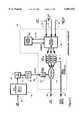
- FIG. 6shows a schematic of a subscriber terminal unit 106 upon which the present invention may be practiced.
- the STU 106is comprised of an Ethernet and ATM Leaf Cable Modem 301 which takes the RF input from connector 302 and provides an optional ethernet interface 805. Cable Modem 301 also sends and receives user ATM cells on lines 308 and 325 as well as management ATM cells on lines 330 and 331. Consequently, lines 308 and 325 provide the means by which the data flow, in terms of user ATM cells, is routed between the Cable Modem 301 and an edge connector 603.
- This means of communicationscan take one of any number of different forms, such as a local bus, a PCI bus, a Utopia type bus, a PCMCIA bus, etc.
- the management ATM cells which provide instructions, commands, protocols, and/or control information to microcontroller 607are routed through lines 330 and 331. Based on the management ATM cells, microcontroller 607 may then control STU 106 accordingly.
- software contained in the management ATM cellscan be downloaded to the read only memory (ROM) 608 or random access memory (RAM) 609 via local interface bus 602.
- the Microcontroller 607may select to pass the software containing instructions and/or management information to the Application Interface Module 610.
- the management ATM cellsmay be passed directly from Cable Modem 301 to the Application Interface Module 610 via the local interface bus 602.
- the Application Interface Module 610physically fits into a receptacle or slot 604 and electrically mates with the edge connector 603.
- AIM 610also includes an external interface 605 which provides an Application Network Interface 606.
- Different versions of AIM modules 610are implemented to provide a variety of enhancements and functionalities beyond those offered by Cable Modem 301. Hence, one can insert an AIM module 610 of choice and substitute it later with a different AIM module.
- an AIM moduleWhen an AIM module is inserted or otherwise coupled to the STU, it must be identified to take advantage of the specific functions that are now available. There are many different ways by which the AIM module can be identified.
- a polling methodcan be utilized whereby the microcontroller 607 of STU 106 periodically checks the edge connector 603 to determine whether there is an AIM module attached to it. If an AIM module is detected, microcontroller 607 transmits a query to the AIM module. In response to the query, the AIM module responds with an identifier. The identifier is indexed against a lookup table or list stored in memory 608 to determine the type and functionalities offered with that AIM module.
- a processor residing within the AIM modulecan detect that the AIM module has mated with an STU. This can be accomplished by detecting power up of the AIM module when power is supplied to the AIM module by the STU through edge connector 603.
- the processortransmits an interrupt signal on local interface bus 602 to microcontroller 607 indicating the presence of the AIM module.
- the microcontroller 607may transmit a query or the AIM module may voluntarily transmit an identification signal.
- the AIM module 610is also designed so that it is hot-pluggable, such that modules may be inserted, removed, and replaced while the STU 106 is powered up and running without interfering with normal STU operations.
- the software which is executed in Micro Controller 607consists of a commonly available Real-Time Operating System (RTOS) such as the VxWorks product from Windriver Systems.
- RTOSReal-Time Operating System
- the ROM 608contains the RTOS, the initial boot code for initiating the operating system, the Power-On Self-Test (POST) procedures for exercising the subscriber terminal unit 106, locating and identifying one or more Application Interface Module 604, initializing the message exchange software and the management application software for the subscriber unit 106.
- the boot codecontains sufficient instructions to all the subscriber terminal unit 106 to initialize itself, perform POST, perform the registration procedure with the Head-end Controller 103, and request a software download for itself.
- the registration methodperforms a downstream channel hunt procedure looking for an active Downstream Communications Channel 701 which is being operated by the Head-end Controller 103. After find such an active channel, the downstream RF processing of the Ethernet and ATM Leaf Cable Modem 301 synchronizes with the downstream message flow and begins to sample downstream messages. When specific registration (acquisition) messages are received by the Subscriber Terminal Unit 106 the management software will tune the Upstream Channel 702 frequency and operating parameters are directed in the downstream registration message. Once positioned, the management process will then begin the registration procedure with the Head-End Controller 103 by exchanging management messages between it and the Head-End Controller 103.
- the application software in the preferred embodimentis a typical embedded controller style software development.
- the interface between the operating system and the hardwareconsists of common interfaces, register, interrupts, and control and data bus signals, etc. These hardware and functional interfaces have been omitted from the schematic of FIG. 6 due to their common availability and well understood nature by anyone skilled in the art of microprocessor hardware and software systems design and development.
- the boot-code software running in the Micro Controller 607contains a software download application process which communicates with the Headend Controller 103 for the purposes of download new operating software into the Subscriber Terminal Unit ROM 608 or RAM 609.
- ROM 608may be implemented by FLASH ROM or other programmable memory or a combination of RAM or ROM memory.
- the download applicationhas the ability to download the whole new boot images or partial images that may be incrementally linked to the running operating system (incremental download).
- FIG. 7shows a schematic diagram of a Headend Communications Controller supporting two MAC scheduling domains and an integrated services interface.
- HCX controller port card 710allows an external device/network to direct and monitor the operations of the HCX, including placing of STUs 106 on channels, moving STUs from channel to channel, managing system bandwidth resources, and maintaining the station provisioning database.
- a number of Ethernet Controller Port Cards 711(also referred to as Ethernet root controllers) are used to provide an interface between the HCX 710 and a number of Ethernet signals.
- the ethernet communicationsis routed according to the Common ATM Switch Fabric 705.
- One or more RF signals 707 containing ATM cellsare sent by the transmit channel port cards 713 to the various STUs 106 via the downstream channel 701.
- the downstream channels 1 and 2 and upstream channels 1 and 2comprise MAC scheduling domain 1, shown as 717.
- downstream and upstream channels 3comprise a different MAC scheduling domain 2, shown as 718.
- RF signals on channels 702 and 704are received by Receiver Channel Port Cards 706 and input to the Common ATM Switch Fabric 705 on line 708.
- the integrated services interfaceincludes Video Controller Port Card 712 and Voice Controller Port Card 714.
- FIG. 8is a schematic diagram illustrating how multiple Ethernet controllers can support different virtual private networks.
- Ethernet Controller #2is assigned to virtual private network W
- Ethernet Controller #3is assigned to virtual private network X.
- Ethernet Controller #2can send a unicast signal (WU3) and a multicast signal (WM) to the Transmit Channel #3.
- Ethernet Controller #3can send a unicast signal (XU3) and a multicast signal (XM) to the same Transmit Channel #3 even though it has a different interface than that of Ethernet Controller #2. And because the same Transmit channel is being used, there is no need for a copy network.
- the Receiver Channel Port Card #3receives both unicast signals from the virtual private network W (W3) as well as from virtual private network X (X3).
- the W3 signalis routed through virtual circuits of the ATM Switch to Ethernet Controller #2 while the X3 signal is routed to the Ethernet Controller #3.
- the present inventionallows for scalability and a variety of interconnections and configurations. This flexibility also allows one Ethernet controller to participate in multiple MAC domains and multiple Ethernet Controllers to participate in any combination of downstream channels, upstream channels, and MAC domains.
- other types of datae.g., video, voice, future services, etc.
- the virtual circuit connection V3 from Voice Controller Port Card 714can be established to carry voice data on the downstream channel 703 through Transmit Channel #3 by means of line 707.
- voice data on channel 704is received by Receiver Channel Port Card #3 and Traffic Scheduler 706. This voice data is input to the Common ATM Switch Fabric 705 by line 708.
- a virtual circuit V3is established to carry the upstream voice data to the Voice Controller Port Card 714 via line 716.
- the same type of virtual circuit connectionscan be established to carry video data corresponding to Video Controller Port Card 712.
- FIG. 9shows a physical view of an STU upon which the present invention may be utilized. It is shown in the currently preferred embodiment, that AIM module 901 can be inserted into and removed from a slot or receptacle 902. AIM module 901 is hot-pluggable such that it may be safely removed or inserted while the STU 106 is powered up and running. STU 106 is coupled to a standard TV 212 through coupler 213 and line 217. STU 106 may also be coupled via 108 to home computing equipment 107.
- AIM modulephysically mating with a connector on the top or sides of the STU; the AIM module can alternatively be coupled through a separate device that is in communication with the STU (e.g., a computer system); it is also feasible to implement a wireless (e.g., RF or infrared) interface between the STU and AIM module such that no actual physical contact is needed.
- the AIM module 901may optionally include an interface to support an application device 903 through line 904.
- the application device 903can be one of any number of different consumer, household, business, electronic, audio/visual, instrumentation, gaming, communications, networking, scanning, display etc., application.
- FIG. 10Ashows a schematic diagram for an installation AIM module 1001.
- the installation AIM moduleis used to aid in reducing the amount of time it takes to install successive STUs.
- An algorithm stored as software instructions in memoryROM 608 or RAM 609) is run by microcontroller 607 to perform the initial channel seek process.
- the channel frequencyis communicated by microcontroller 607 to microprocessor 1002 over local bus 602, through edge connector 603 and local bus 1006 to microprocessor 1002.
- a standard bus extension logic 1003is used to bridge together the two local buses 602 and 1006.
- This frequency informationis then stored in some form of nonvolatile memory (e.g., PROM, ROM, Flash ROM, RAM) 1004 or 1005.
- the cable service representativecan remove the installation AIM 1001 and insert it into a different STU which is to be installed.
- the cable service representativecan remove the installation AIM 1001 and insert it into a different STU which is to be installed.
- the cable modem 301 of the second STUfirst boots up, its microcontroller checks to determine whether an installation AIM 1001 is currently installed. If an installation AIM 1001 has been installed, microprocessor 1002 reads the list of preferred frequencies that had been previously stored in its nonvolatile memory 1004 or 1005 and conveys this information to microcontroller 607. Thereupon, microcontroller 607 tries the preferred frequencies to determine whether there is a match.
- microcontroller 607If a match is found, the channel is acquired and the installation process is completed much more quickly. Otherwise, microcontroller 607 must perform the standard channel seek algorithm, which often takes much longer in time to complete. Microcontroller 607 may then add or update the preferred frequency list with the new frequency. This AIM is also referred to as a "wild card" function.
- the Subscriber Terminal Unit 106 Micro Controller 607has the ability via hardware logic interface bus to communicate with a Application Interface Module 604.
- AIM module identificationis achieve by sampling an ID code on the hardware interface for simple interfaces (those without on-board controllers) and also by exchanging messages with the AIM 604 on-board processor which is detailed in FIG. 10a.
- Each type of AIM 604would have a distinctive code allowing the Micro Controller 607 to perform additional tests and configuration.
- the Micro Controller 607may access RAM 1005 or FLASHROM 1004 on the AIM 604 in order to download instructions for Micro Processor 1002 (if present) or to program memory.
- the messaging software of Micro Controller 607communicates with the message software on the Micro Processor 1002 to cause configuration changes, operational changes, to download software from the Head-End Controller to the AIM 604 FLASH ROM 1004 or RAM 1005, or to perform other activities specific to the operation of the specific AIM 604 functions.
- the Micro Controller 607also has the ability to shut down or deconfigure the AIM 604 module inhibit operation. This feature is necessary so that the cable operator can authorize services that are supplied via the AIM 604. Note that other methods may be employed to identify AIM 604 cards other that those that have been described here.
- the software which is executed in Micro Processor 1002consists of commonly available Real-Time Operating System (RTOS) such as the VxWorks product from Windriver Systems.
- RTOSReal-Time Operating System
- the ROM 1004contains the RTOS, the initial boot code for initializing the operating system, the Power-On Self-Test (POST) procedures for exercising the AIM 604, initializing the message exchange software and the management application software for the AIM 604.
- POSTPower-On Self-Test
- the boot codecontains sufficient instructions to all the AIM 604 to initialize itself, perform POST, perform a message exchange with the management process running on Micro Controller 607, and initiate any necessary software downloads.
- RAM 1005 or ROM 1004there may be no software loaded in RAM 1005 or ROM 1004, requiring the Micro Controller 607 to write a program to RAM 1005 or FLASH ROM 1004 and then resetting the Micro Processor 1002 so that it will begin operating on the new code.
- the interface between the operating system running in Micro Processor 1002 and the hardwareconsists of common interfaces, register interrupts, and control and data bus signals, etc. These hardware and functional interfaces have been omitted from the schematic of FIG. 10a due to their common availability and well understood nature by anyone skilled in the art of micro-processor hardware and software systems design and development.
- the AIM 604 and Subscriber Terminal Unit 106 and Edge Connector 603have been implemented as a hot pluggable device. As such, the Subscriber Terminal Unit may have be running and the AIM 604 is then inserted making contact with Edge Connector 603.
- the Micro Controller 607continues to run but is made aware of the presence of the AIM 604 via hardware interrupt lines, a change to a status register which is periodically sample, or via message that may be placed in a shared memory portion of RAM 609 by the Micro Processor 1002.
- the Micro Controller 607can then initiate a query the Head-End Controller 103 to authorize operation of the specific type of AIM 604 and to download new software to the Subscriber Terminal Unit 106 ROM 608 or RAM 609 or to the AIM 604 RAM 1005 or ROM 1004 if required.
- Micro Controller 607 and Micro Processor 1002have been omitted from this embodiment as there are many different equivalent systems that may be implemented by those skilled in the art of processor to process communication mechanisms, or in processor to input/output controller operations.
- FIG. 10Bis a flowchart describing the steps for performing the installation of STUs with the aid of an installation AIM module.
- the STUchecks to determine whether an installation AIM module or "wild card" is resident, step 1010. If the STU does not detect an installation AIM module, it performs a standard channel seek algorithm to find and access an available channel, step 1050. Otherwise, if an installation AIM module has been inserted into that STU and is detected by the STU, step 1020 reads the first frequency from the list of preferred frequencies that is stored in the AIM module. Based on this frequency, the STU determines whether there is a match with an available channel on the CATV system, step 1030.
- step 1080If there is a match, the installation process is complete, and the service representative removes the installation AIM module and repeats this process for subsequent installations, step 1080. Otherwise, if the first read frequency does not result in a match, the STU reads the next frequency from the preferred list of frequencies, step 1040, to determine whether there are any matches, step 1030. If all the frequencies in the list has already been tried and there are still no matches yet, the STU performs a standard algorithmic seek process to find and acquire an available channel, step 1050. At the end of successfully finding an available channel, a determination is made in step 1060 as to whether there is an installation AIM module currently residing within the STU. If there is an installation AIM module, the frequency of the available channel found in step 1050 is stored in the AIM module as part of the preferred list of frequencies, step 1070. At this point, the installation process is complete, step 1080.
- FIG. 11shows a schematic diagram of a telephony AIM module.
- Telephony AIM module 1101may be inserted into the slot within the STU to provide telephony services in addition to the high speed digital data transmissions originally supported by cable modem 301.
- microcontroller 607is informed by microprocessor 1002. Thereupon, microcontroller notifies the Headend Controller of this condition through the transmission of management cells.
- the HCX port carddetermines whether that subscriber is authorized to make telephone calls through his or her STU. If the subscriber is authorized, the proper virtual circuits are established in the Common ATM Switch Fabric to provide voice data through the CATV system for that particular STU.
- Incoming and outgoing voice datais routed through the edge connector 603 to provide full duplex capability.
- the voice datais buffered by an ATM queue management circuit 1102, which basically serves as a first-in-first-out (FIFO) buffer.
- the ATM queue management circuit 1102also performs scheduling and prioritizing functions.
- softwarecan be downloaded through the CATV system to the microcontroller 607 and/or microprocessor 1002 by means of the management cells.
- This softwarecontains the instructions for enabling the STU to handle voice data and for supporting options, such as caller ID, multiple phone lines, party lines, ISDN, call forwarding, voice mail, paging, etc. These enhanced options are enabled by a standard programmable digital signal processor (DSP) chip 1104.
- DSPdigital signal processor
- Telephony AIM module 1101can support one or more such telephone lines.
- a subscriber line interface cardSLIC
- SLICsubscriber line interface card
- the telephony AIM module 1101supports Basic Rate ISDN (BRI) and/or T1/E1 circuits.
- FIG. 12shows a schematic diagram of a field diagnostic AIM module. If a subscriber's STU is malfunctioning, a service technician is sent to test the STU. The service technician first inserts the field diagnostic AIM module 1201 in the STU, either while the STU is up and running or rebooting the STU upon insertion. Microcontroller 607 detects the presence of field diagnostic AIM module 1201 and places the STU in a test mode so that field diagnostics can be performed. There are a number of tests which can be executed with the field diagnostic AIM module 1201 in place. For example, software contained in memory 1004 or 1005 can cause microprocessor 1002 to analyze certain cells up and down the entire CATV system.
- test cellscan be transmitted to test particular parts of the STU, fiber-coax network, or the Headend unit.
- the STU's performance characteristicse.g., bit error rate, frequencies, etc.
- the contents of the STU's memorycan also be scanned to determine the state of the STU.
- a serial interface (e.g., RS-232) 1203is optionally provided so that other test equipment can be coupled to the STU via the field diagnostic AIM module 1201.
- a computer systeme.g., a laptop or portable computer
- the results of these tests and diagnosticscan be displayed on an LCD display 1202, by the test equipment, or computer system.
- the field diagnostic AIM module 1201gives the service technician the ability to override many of the normal functions and operations associated with the STU. Furthermore, communications with the headend unit for testing purposes can be established, and software from the headend unit can be downloaded to the AIM module or STU memory.
- the softwarecan be custom tailored to test different types and configurations of STUs and their respective circuits, features, options, and functions. For example, software can be invoked to read the contents stored in memory, noise or some other source of error can intentionally be injected for testing circuits, test messages can be routed the length of the cable network including the headend controller and cards to test any part or combination of the network, frequency measurements can be taken, the signal to noise ratio can be measured, signal amplitudes and power levels can be checked, etc.
- the field diagnostic functionsas a separate AIM module, costs are reduced because rather than incorporating the diagnostic circuitry into each and every STU, a few field diagnostic AIM modules can service a multitude of STUs. Moreover, because the field diagnostic AIM module 1201 is detachable, the field technician can remove the module from the STU when diagnostics is completed on that particular STU and carry the AIM module to the next STU for troubleshooting. Hence, it is possible to restrict access of the diagnostic AIM modules to only authorized service technicians, thereby preventing subscribers from gaining access to diagnostic functions.
- FIG. 13shows a schematic diagram of an advanced home interface module 1301.
- the advanced home interface module 1301provides enhanced network interface(s) for supporting formats and standards other than Ethernet.
- supportis provided by advanced home network module 1301 for consumer based interfaces.
- an IEEE 1394 block 1303can be coupled onto the local bus 1006 to receive and send data in the form of IEE 1394 or "Firewire.”
- the usermay choose to include a Universal Serial Bus (USB) connection via USB block 1302.
- home electronicse.g., stereo, HDTV, VCR, camcorder, joystick, mouse, keyboard, phone, USB device, etc.
- STUSerial Bus
- the advanced home interface module 1301can be adapted and has the flexibility to provide interfaces to meet future standards. Again, notification and authorization are made by utilizing the management ATM cells. Furthermore, in the currently preferred embodiment, all information (e.g., Ethernet, IEEE 1394, USB, etc.) is converted into ATM cells which are transmitted through the CATV system and later re-converted back as necessary.
- all informatione.g., Ethernet, IEEE 1394, USB, etc.
- packets from the headend controllercan be output from advanced home interface module 1301 as IEEE 1394 or USB; IEEE 1394 or USB data can be input to the STU via the advanced home interface module 1301; IEEE 1394 data can be input through one port of the advanced home interface module 1301 and output as USB on a separate port of the advanced home interface module 1301; IEEE 1394 data can be input through one port of the advanced home interface module 1301 and output as IEEE 1394 data on a separate port of the advanced home interface module 1301; USB data can be input through one port of the advanced home interface module 1301 and output as IEEE 1394 on a separate port of the advanced home interface module 1301; and USB data can be input through one port of the advanced home interface module 1301 and output as USB data on a separate port of the advanced home interface module 1301.
- microprocessor 1002recognizing the format of the incoming signal and converting the incoming signal into ATM packets for routing purposes. For example, the signals received by IEEE 1394 block 1303 are converted from IEEE 1394 format by microprocessor 1002 into ATM packets. These ATM packets can then be routed upstream to the headend controller. The same or different ATM packets can be converted into USB format by microprocessor 1002 for output by the USB block 1302.
- FIG. 14shows a schematic diagram of an Asynchronous Transfer Mode AIM module.
- the Asynchronous Transfer Mode AIM module 1401is used to provide support for an ATM25 cell path to and from the STU.
- ATM cellsare input to an ATM interface 1405.
- User ATM cellsare then queued, buffered, and scheduled by ATM Queue Manager 1403 before being transferred over edge connector 603 to the Cable Modem 301.
- microprocessor 1002may provide bridging, gateway, packet conversion, or directory services. Thereby, packets can be readily monitored and/or exchanged through interfaces 1302-1303 or the RF.
- FIG. 15shows a schematic diagram of a Television AIM module.
- the Television AIM module 1501is used to provide a TV interface for the Cable Modem 301.
- Standard ATM cells containing video datais sent via line 308 downstream to edge connector 603 and ATM Queue Manager 1503.
- the ATM cellsare then input on line 1504 to the Digital Video Signal Processor 1505 which converts the ATM cells into standard NTSC or HDTV television signals which are input as RF to the subscriber's television set on line 1502.
- Various TV control functionse.g., channel selection, volume control, picture-in-picture, sound, contrast, etc.
- video-on-demand functionalityis provided by converting infrared commands to packets for transfer to the video controller in the headend unit for further processing.
- a subscribercan select any one of a number of movies to receive. The selection is input via the Remote Control 1506 and conveyed by microprocessor 1002 to microcontroller 607. The selection is then transmitted upstream in the form of one or more management ATM cells to the HCX Controller. Based on this information, the appropriate movie title is then retrieved from a disk array or other mass storage device. The appropriate virtual connections are established and the video is sent downstream by the Video Controller Port Card to the requesting STU in the form of ATM cells. These ATM cells are then converted by the Digital Video Signal Processor 1505 into RF signals for input to the subscriber's TV set.
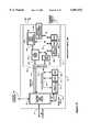
- FIG. 16shows a schematic diagram of an ADSL terminal unit that has an interface with an application interface module.
- ADSLis used to include all the different types of Digital Subscriber Line (DSL) technologies, such as Rate Adjustable Digital Subscriber Line (RADSL), Symmetric Digital Subscriber Line (SDSL), High Speed Digital Subscriber Line (HDSL), etc.
- DSLDigital Subscriber Line
- RADSLRate Adjustable Digital Subscriber Line
- SDSLSymmetric Digital Subscriber Line
- HDMIHigh Speed Digital Subscriber Line
- FIG. 16is similar to that of an STU described above, except that the Ethernet and ATM Leaf ADSL Modem 1601 replaces the Ethernet and ATM Leaf Cable Modem 301 of FIG. 3.
- the RF partsare replaced with commonly available ADSL to ATM components.
- the Cable Modem RF to ATM Receiver 305, the Diplexor 303, and the Cable Modem ATM to RF Transmitter 328have been replaced with commonly available chipset that interfaces ADSL to ATM.
- One such commercially available chipsetis the DynaMiTe MTK-20120 series (including the MTC-20124 Analog Front-end, MTC-20125 Modem, and MTC-20126 ATM Handler) manufactured by Alcatel Telecom of Paris, France.
- Datainterfaces with the ADSL terminal unit 1603 through the twisted pair connection 1602 according to established ADSL standards.
- Ethernet and ATM Leaf ADSL Modem 1601transmits and receives ATM cells containing user data on lines 1604 and 1605 to/from the edge connector 603.
- Edge connector 603provides the interface to a detachable AIM module which gives enhanced functionality to the ADSL terminal unit 1603.
- the ATM cells containing management informationare conveyed on lines 1606 and 1607 to/from microcontroller 1610.
- Data as well as software on local interface bus 1611can be stored by the ROM 1608 or RAM 1609 memories.
- FIG. 17shows a representative model of an ADSL delivery system for supporting an ADSL terminal unit.
- FIG. 17shows the interconnects between a Subscriber Management System And Server 1701, through an ATM link 1702, to the ADSL Termination System and ATM Switch 1703.
- the Subscriber Management System And Server 1701provides equivalent functions as the Headend Controller.
- an ADSL terminal unitcan dial in over the ATM network provided by the ADSL, contact the manager, establish proper authorization, and request software downloads which are serviced by the server 1701.
- the ADSL Termination System 1703interfaces through the copper local loop 1704 into a Central Telephone Office Distribution Frame 1705 which has access to the copper pair local loops.
- the actual Local Loop Plantis shown as 1706 which distributes twisted-pair local loops 1707 out from the Central Office 1705 to reach subscriber premises.
- the ADSL Terminal Units 1603connect up to 1707.
- the ADSL Termination System and ATM Switch 1703is also coupled through line 1709 to an ATM Backhaul Network 1708 which grants access to the Internet as well as other types of networks.
- FIG. 18shows a subscriber terminal unit having an ADSL AIM module 1801.
- An ADSL devicecan be coupled to the ADSL module 1801 through twisted pair wires 1802 to a programmable DSP 1104.
- the programmable DSP 1104converts incoming ADSL data to ATM cells for input to the ATM Queue Management 1102 and local bus 1006. These ATM cells containing ADSL data are sent to the Ethernet and ATM Leaf Cable Modem 301 which performs the packet conversion and ATM transmission.
- the programmable DSO 1104also converts ATM cells received by the STU 106 from the cable network line 302 back to ADSL data for output to the connected ADSL device on line 1802.
- an ADSL devicee.g., ADSL modem
Landscapes
- Engineering & Computer Science (AREA)
- Computer Networks & Wireless Communication (AREA)
- Signal Processing (AREA)
- Data Exchanges In Wide-Area Networks (AREA)
- Communication Control (AREA)
Abstract
Description
Claims (89)
Priority Applications (3)
| Application Number | Priority Date | Filing Date | Title |
|---|---|---|---|
| US08/881,942US6081533A (en) | 1997-06-25 | 1997-06-25 | Method and apparatus for an application interface module in a subscriber terminal unit |
| PCT/US1998/012972WO1998059453A2 (en) | 1997-06-25 | 1998-06-24 | Method and apparatus for an application interface module in a subscriber terminal unit |
| AU82608/98AAU8260898A (en) | 1997-06-25 | 1998-06-24 | Method and apparatus for an application interface module in a subscriber terminal unit |
Applications Claiming Priority (1)
| Application Number | Priority Date | Filing Date | Title |
|---|---|---|---|
| US08/881,942US6081533A (en) | 1997-06-25 | 1997-06-25 | Method and apparatus for an application interface module in a subscriber terminal unit |
Publications (1)
| Publication Number | Publication Date |
|---|---|
| US6081533Atrue US6081533A (en) | 2000-06-27 |
Family
ID=25379531
Family Applications (1)
| Application Number | Title | Priority Date | Filing Date |
|---|---|---|---|
| US08/881,942Expired - LifetimeUS6081533A (en) | 1997-06-25 | 1997-06-25 | Method and apparatus for an application interface module in a subscriber terminal unit |
Country Status (3)
| Country | Link |
|---|---|
| US (1) | US6081533A (en) |
| AU (1) | AU8260898A (en) |
| WO (1) | WO1998059453A2 (en) |
Cited By (134)
| Publication number | Priority date | Publication date | Assignee | Title |
|---|---|---|---|---|
| WO2001037105A1 (en)* | 1999-11-17 | 2001-05-25 | Granite Microsystems, Inc. | Device bay system with surprise removal prevention for supporting and controlling usb and ieee 1394 peripheral devices |
| US6262982B1 (en)* | 1996-11-12 | 2001-07-17 | Starguide Digital Networks, Inc. | High bandwidth broadcast system having localized multicast access to broadcast content |
| US20010011375A1 (en)* | 2000-01-13 | 2001-08-02 | Yun Hwa Young | Open cable set-top box diagnosing system and method thereof |
| US6272546B1 (en)* | 1998-03-12 | 2001-08-07 | Sony Corporation | Method of and apparatus for managing resource allocation and bandwidth overflow in a cooperative, distributed computing environment |
| US20010026557A1 (en)* | 1999-12-30 | 2001-10-04 | Gralf Gaedeken | Interface link layer device to build a distributed network |
| US6347294B1 (en)* | 1998-09-22 | 2002-02-12 | International Business Machines Corporation | Upgradeable highly integrated embedded CPU system |
| US6350239B1 (en)* | 1999-12-28 | 2002-02-26 | Ge Medical Systems Global Technology Company, Llc | Method and apparatus for distributed software architecture for medical diagnostic systems |
| US20020048275A1 (en)* | 1997-12-16 | 2002-04-25 | Antonio Atwater | Method and apparatus for receiving full-motion digital video multi-casts, interactive data and interactive voice via a DSL circuit |
| US20020059637A1 (en)* | 2000-01-14 | 2002-05-16 | Rakib Selim Shlomo | Home gateway for video and data distribution from various types of headend facilities and including digital video recording functions |
| US20020064218A1 (en)* | 2000-06-29 | 2002-05-30 | Phonex Broadband Corporation | Data link for multi protocol facility distributed communication hub |
| US20020069417A1 (en)* | 2000-08-30 | 2002-06-06 | Avi Kliger | Home network system and method |
| US6414952B2 (en)* | 1997-08-28 | 2002-07-02 | Broadcom Homenetworking, Inc. | Virtual gateway system and method |
| US6421728B1 (en)* | 1997-12-31 | 2002-07-16 | Intel Corporation | Architecture for communicating with and controlling separate upstream and downstream devices |
| US20020120941A1 (en)* | 2001-02-28 | 2002-08-29 | Kabushiki Kaisha Toshiba | Cable modem apparatus and frequency setting method applied thereto |
| US20020157115A1 (en)* | 2001-04-24 | 2002-10-24 | Koninklijke Philips Electronics N.V. | Wireless communication point of deployment module for use in digital cable compliant devices |
| US20020159402A1 (en)* | 1998-07-28 | 2002-10-31 | Yehuda Binder | Local area network of serial intelligent cells |
| US6493348B1 (en)* | 1997-12-05 | 2002-12-10 | Telcordia Technologies, Inc. | XDSL-based internet access router |
| US6496862B1 (en)* | 1998-08-25 | 2002-12-17 | Mitsubishi Electric Research Laboratories, Inc. | Remote monitoring and control of devices connected to an IEEE 1394 bus via a gateway device |
| US20020191772A1 (en)* | 2001-06-18 | 2002-12-19 | International Business Machines Corporation | Service logic execution environment for telecommunications service components |
| US20020194605A1 (en)* | 2001-05-18 | 2002-12-19 | T.M.T. Third Millenium Technologies Ltd. | Cableran networking over coaxial cables |
| US20030005450A1 (en)* | 2001-07-01 | 2003-01-02 | Gordon Smith | Method and system for connecting high speed data communication signals to a residentual gateway |
| US20030021237A1 (en)* | 2001-06-08 | 2003-01-30 | Min Jonathan S. | Receiver having integrated spectral analysis capability |
| US6515995B1 (en)* | 1997-12-30 | 2003-02-04 | Lg Information & Communications, Ltd. | Asymmetric digital subscriber line interfacing system in an ATM exchange system |
| US20030035442A1 (en)* | 2001-04-14 | 2003-02-20 | Eng John Wai Tsang | Full-service broadband cable modem system |
| US20030037105A1 (en)* | 2000-12-11 | 2003-02-20 | Kazuhiro Yamada | Terminal and repeater |
| US20030040881A1 (en)* | 2001-08-14 | 2003-02-27 | Perry Steger | Measurement system including a programmable hardware element and measurement modules that convey interface information |
| US20030046380A1 (en)* | 2001-08-14 | 2003-03-06 | Perry Steger | Measurement module interface protocol database and registration system |
| US6535927B1 (en)* | 1998-05-23 | 2003-03-18 | Samsung Electronics Co., Ltd. | System for processing protocol for internet services employing serial line and ATM network |
| US20030056228A1 (en)* | 2001-09-14 | 2003-03-20 | Foster Mark J. | Method and apparatus for increasing bandwidth assignment latency in a data transmission scheme which employs the aloha protocol, to thereby improve bandwidth efficiency |
| US20030058837A1 (en)* | 2001-09-27 | 2003-03-27 | Lisa Denney | Method and system for upstream priority lookup at physical interface |
| US20030066082A1 (en)* | 2000-08-30 | 2003-04-03 | Avi Kliger | Home network system and method |
| US6546022B1 (en)* | 1998-04-03 | 2003-04-08 | Sprint Communications Company, L.P. | Method, system and apparatus for processing information in a telecommunications system |
| US20030084440A1 (en)* | 2001-10-26 | 2003-05-01 | George Lownes | Method of providing a code upgrade to a host device having a smart card interface |
| US6590897B1 (en) | 1999-03-08 | 2003-07-08 | Efficient Networks, Inc. | System and method for bridging universal serial bus and asynchronous transfer mode communication links |
| US6603744B2 (en)* | 1997-08-07 | 2003-08-05 | International Business Machines Corporation | Connection establishment method, communication method, state change transmission method, state changing method, wireless apparatus, wireless device, and computer |
| US20030159089A1 (en)* | 2002-02-21 | 2003-08-21 | Dijoseph Philip | System for creating, storing, and using customizable software test procedures |
| US20030169774A1 (en)* | 2002-03-07 | 2003-09-11 | Del Prado Pavon Javier | Internal signaling method to support clock synchronization of nodes connected via a wireless local area network |
| US6633583B1 (en)* | 1998-12-18 | 2003-10-14 | Intel Corporation | Wireless universal serial bus receiver |
| US6636890B1 (en)* | 1997-11-28 | 2003-10-21 | International Business Machines Corporation | Stand-alone internet mailbox for cable subscribers |
| US6654835B1 (en)* | 2000-03-23 | 2003-11-25 | International Business Machines Corporation | High bandwidth data transfer employing a multi-mode, shared line buffer |
| US6665303B1 (en)* | 1998-01-05 | 2003-12-16 | Kabushiki Kaisha Toshiba | Scheme for realizing communications through external network from contents processing device connected to local network in home environment |
| US20030233667A1 (en)* | 2002-06-17 | 2003-12-18 | Abs-Cbn Broadcasting Corporation | Method and apparatus for implementing a scaled upgrading of an upgradeable set-top box |
| US6687486B2 (en)* | 2002-01-31 | 2004-02-03 | General Instrument Corporation | Method and apparatus to configure, provision and control a set-top terminal |
| US6690782B2 (en) | 2001-06-18 | 2004-02-10 | International Business Machines Corporation | Service logic execution environment connector to client interface |
| US6747979B1 (en)* | 1998-10-27 | 2004-06-08 | Hewlett-Packard Development Company, L.C. | Method and apparatus for bridging between networks |
| US6771649B1 (en)* | 1999-12-06 | 2004-08-03 | At&T Corp. | Middle approach to asynchronous and backward-compatible detection and prevention of ARP cache poisoning |
| US6771322B1 (en)* | 1998-03-19 | 2004-08-03 | Scm Microsystems Gmbh | Interface device between a semiconductor storage medium for multimedia and a standard video terminal |
| US6772437B1 (en)* | 1999-07-28 | 2004-08-03 | Telefonaktiebolaget Lm Ericsson | Cable modems and systems and methods for identification of a noise signal source on a cable network |
| US20040172658A1 (en)* | 2000-01-14 | 2004-09-02 | Selim Shlomo Rakib | Home network for ordering and delivery of video on demand, telephone and other digital services |
| US20040177381A1 (en)* | 2002-09-05 | 2004-09-09 | Tiaris, Inc. | Home network system which supports legacy digital set top box devices |
| US6795438B1 (en)* | 1998-10-28 | 2004-09-21 | Intel Corporation | Method and apparatus for extending point-to-point/asynchronous transfer mode services to client computer systems |
| US6807195B1 (en) | 1999-09-29 | 2004-10-19 | General Instrument Corp. | Synchronization arrangement for packet cable telephony modem |
| US20040255326A1 (en)* | 2000-12-28 | 2004-12-16 | John Alson Hicks | Digital residential entertainment system |
| US20040261112A1 (en)* | 2000-12-28 | 2004-12-23 | Hicks John Alson | System and method for multimedia on demand services |
| US20050007984A1 (en)* | 2003-05-02 | 2005-01-13 | Interdigital Technology Corporation | Method and architecture for accessing an internet protocol multimedia subsystem (IMS) over a wireless local area network (WLAN) |
| US20050018691A1 (en)* | 2003-07-24 | 2005-01-27 | Riedl Steven E. | Technique for communicating relatively high and low priority data between a terminal and a remote location |
| US6853647B1 (en)* | 1999-02-17 | 2005-02-08 | Covad Communications Group, Inc. | System method and network for providing high speed remote access from any location connected by a local loop to a central office |
| US20050086694A1 (en)* | 2000-12-28 | 2005-04-21 | John Hicks | Digital residential entertainment system |
| US6904049B1 (en)* | 1999-04-28 | 2005-06-07 | Juniper Networks, Inc. | Data transfer system and method for transferring data packets over an ATM link |
| US20050138213A1 (en)* | 2003-12-23 | 2005-06-23 | Lee Sang-Jun | Open cable applying apparatus and method of allowing internet |
| US6917614B1 (en)* | 1999-09-17 | 2005-07-12 | Arris International, Inc. | Multi-channel support for virtual private networks in a packet to ATM cell cable system |
| US6928656B1 (en)* | 1999-05-14 | 2005-08-09 | Scientific-Atlanta, Inc. | Method for delivery of IP data over MPEG-2 transport networks |
| US20050183014A1 (en)* | 2004-02-18 | 2005-08-18 | Yung-Da Lin | Audio-video signal transceiving processing device |
| US20050180411A1 (en)* | 2000-01-18 | 2005-08-18 | Mari Horiguchi | Communication method and communication apparatus |
| US20050190793A1 (en)* | 2003-12-16 | 2005-09-01 | Alcatel | System comprising a terminal system, an access multiplexer and a network |
| US6965614B1 (en)* | 1999-11-12 | 2005-11-15 | Nortel Networks Limited | Method and system for communications between different types of devices |
| US20050286900A1 (en)* | 2003-03-25 | 2005-12-29 | Infinite Media Solutions, Llc | Intelligent modular multimedia data distribution system |
| US20060075441A1 (en)* | 2004-10-06 | 2006-04-06 | Sony Corporation | Method and system for a personal video recorder comprising multiple removable storage/tuner units |
| US20060074807A1 (en)* | 2004-10-06 | 2006-04-06 | Sony Corporation | Method and system for content sharing and authentication between multiple devices |
| US7047554B1 (en)* | 1998-12-09 | 2006-05-16 | Intel Corporation | System and method for integrating and controlling audio/video devices |
| US20060109847A1 (en)* | 2004-09-27 | 2006-05-25 | Sou Satou | Subscriber line accommodation apparatus and packet filtering method |
| US20060126515A1 (en)* | 2004-12-15 | 2006-06-15 | Ward Robert G | Filtering wireless network packets |
| US20060135059A1 (en)* | 2001-10-12 | 2006-06-22 | Bellsouth Intellectual Property Corporation | Method using a set-top box communicating between a remote data network and a wireless communication network |
| US7089577B1 (en)* | 2000-01-14 | 2006-08-08 | Terayon Communication Systems, Inc. | Process for supplying video-on-demand and other requested programs and services from a headend |
| US20060190209A1 (en)* | 2001-08-14 | 2006-08-24 | National Instruments Corporation | Programmable hardware element with cartridge controllers for controlling modular measurement cartridges that convey interface information |
| US20060209943A1 (en)* | 2000-04-21 | 2006-09-21 | Apple Computer, Inc. | Method and apparatus for generating jitter test patterns on a high performance serial bus |
| US7181017B1 (en) | 2001-03-23 | 2007-02-20 | David Felsher | System and method for secure three-party communications |
| US20070070911A1 (en)* | 2005-09-29 | 2007-03-29 | Goldberg Keith J | Method for testing links in a wireless network |
| US20070091915A1 (en)* | 2000-04-19 | 2007-04-26 | Serconet Ltd. | Network combining wired and non wired segments |
| EP1841169A1 (en)* | 2006-03-27 | 2007-10-03 | Alcatel Lucent | Communication system with remote controlling of a wireless transmission means |
| US20070245086A1 (en)* | 2006-04-12 | 2007-10-18 | Brian Keith Odom | Generating a Data Stream from Cartridge Controllers Using a Plurality of Measurement Cartridges |
| US7304945B1 (en)* | 2000-02-14 | 2007-12-04 | Ericsson Ab | Method and apparatus for dynamic bitmap generator scheduler |
| US20080007898A1 (en)* | 2005-03-25 | 2008-01-10 | Akihiro Tatsuta | Front-end device of set-top box for two-way communication |
| US20080115189A1 (en)* | 2006-11-10 | 2008-05-15 | Stephane Lejeune | TV-centric system |
| US20080117929A1 (en)* | 2006-11-20 | 2008-05-22 | Broadcom Corporation | System and method for retransmitting packets over a network of communication channels |
| US20080130779A1 (en)* | 2006-11-20 | 2008-06-05 | Broadcom Corporation | Apparatus and methods for compensating for signal imbalance in a receiver |
| US20080168517A1 (en)* | 2003-05-22 | 2008-07-10 | Allen James D | System and method for evaluating callback functionality in a satellite television network |
| US20080178229A1 (en)* | 2000-08-30 | 2008-07-24 | Broadcom Corporation | Home network system and method |
| US20080298241A1 (en)* | 2007-05-31 | 2008-12-04 | Broadcomm Corporation | Apparatus and methods for reduction of transmission delay in a communication network |
| US20080304521A1 (en)* | 2007-06-05 | 2008-12-11 | Koninklijke Philips Electronics, N.V. | Internal signaling method to support clock synchronization of nodes connected via a wireless local area network |
| US20090007211A1 (en)* | 2007-06-29 | 2009-01-01 | Embarq Holdings Company, Llc | Cable set-top box with voice over internet protocol |
| US20090003374A1 (en)* | 2007-06-29 | 2009-01-01 | Embarq Holding Company Llc | Method and apparatus for providing power over a data network |
| US20090003386A1 (en)* | 2007-06-29 | 2009-01-01 | Embarq Holdings Company, Llc | Integrated set-top box DSL VOIP WIFI device |
| US7478006B2 (en) | 2001-08-14 | 2009-01-13 | National Instruments Corporation | Controlling modular measurement cartridges that convey interface information with cartridge controllers |
| US20090060151A1 (en)* | 1999-07-20 | 2009-03-05 | Serconet, Ltd | Network for telephony and data communication |
| US7587368B2 (en) | 2000-07-06 | 2009-09-08 | David Paul Felsher | Information record infrastructure, system and method |
| US20090279643A1 (en)* | 2008-05-06 | 2009-11-12 | Broadcom Corporation | Unbiased signal-to-noise ratio estimation for receiver having channel estimation error |
| US7656904B2 (en) | 2003-03-13 | 2010-02-02 | Mosaid Technologies Incorporated | Telephone system having multiple distinct sources and accessories therefor |
| US7688841B2 (en) | 2003-07-09 | 2010-03-30 | Mosaid Technologies Incorporated | Modular outlet |
| US7697522B2 (en) | 2006-11-20 | 2010-04-13 | Broadcom Corporation | Systems and methods for aggregation of packets for transmission through a communications network |
| US7739717B1 (en) | 2004-07-13 | 2010-06-15 | The Directv Group, Inc. | System and method for performing diagnostics for a customer IRD in a satellite television system |
| US20100158013A1 (en)* | 2008-12-22 | 2010-06-24 | Broadcom Corporation | Systems and methods for reducing latency and reservation request overhead in a communications network |
| US20100158021A1 (en)* | 2008-12-22 | 2010-06-24 | Broadcom Corporation | Systems and methods for physical layer ("phy") concatenation in a moca network |
| US7782850B2 (en) | 2006-11-20 | 2010-08-24 | Broadcom Corporation | MAC to PHY interface apparatus and methods for transmission of packets through a communications network |
| US20100246586A1 (en)* | 2009-03-30 | 2010-09-30 | Yitshak Ohana | Systems and methods for retransmitting packets over a network of communication channels |
| US20100284474A1 (en)* | 2009-05-05 | 2010-11-11 | Broadcom Corporation | Transmitter channel throughput in an information network |
| US7860084B2 (en) | 2001-10-11 | 2010-12-28 | Mosaid Technologies Incorporated | Outlet with analog signal adapter, a method for use thereof and a network using said outlet |
| US7911992B2 (en) | 2002-11-13 | 2011-03-22 | Mosaid Technologies Incorporated | Addressable outlet, and a network using the same |
| US20110119016A1 (en)* | 2009-11-18 | 2011-05-19 | Patel Kunal H | Deterministic Reconfiguration of Measurement Modules Using Double Buffered DMA |
| US20110206042A1 (en)* | 2010-02-23 | 2011-08-25 | Moshe Tarrab | Systems and methods for implementing a high throughput mode for a moca device |
| US8238227B2 (en) | 2008-12-22 | 2012-08-07 | Broadcom Corporation | Systems and methods for providing a MoCA improved performance for short burst packets |
| US8243918B2 (en) | 2004-02-16 | 2012-08-14 | Mosaid Technologies Incorporated | Outlet add-on module |
| US20120278186A1 (en)* | 2011-04-28 | 2012-11-01 | Ad-X Limited | Method of tracking software application internet downloads |
| US8363797B2 (en) | 2000-03-20 | 2013-01-29 | Mosaid Technologies Incorporated | Telephone outlet for implementing a local area network over telephone lines and a local area network using such outlets |
| US8515773B2 (en) | 2001-08-01 | 2013-08-20 | Sony Corporation | System and method for enabling distribution and brokering of content information |
| US8582598B2 (en) | 1999-07-07 | 2013-11-12 | Mosaid Technologies Incorporated | Local area network for distributing data communication, sensing and control signals |
| US8600830B2 (en) | 2003-02-05 | 2013-12-03 | Steven M. Hoffberg | System and method for providing a payment to a non-winning auction participant |
| US8611327B2 (en) | 2010-02-22 | 2013-12-17 | Broadcom Corporation | Method and apparatus for policing a QoS flow in a MoCA 2.0 network |
| US8719893B2 (en) | 1999-03-15 | 2014-05-06 | Sony Corporation | Secure module and a method for providing a dedicated on-site media service |
| US8756565B2 (en) | 2012-02-17 | 2014-06-17 | National Instruments Corporation | Modifying a target system configuration to utilize a different synchronization module for performing synchronization among multiple programmable hardware elements |
| US8867355B2 (en) | 2009-07-14 | 2014-10-21 | Broadcom Corporation | MoCA multicast handling |
| US8942250B2 (en) | 2009-10-07 | 2015-01-27 | Broadcom Corporation | Systems and methods for providing service (“SRV”) node selection |
| US8979871B2 (en) | 2009-08-13 | 2015-03-17 | Monteris Medical Corporation | Image-guided therapy of a tissue |
| US9112717B2 (en) | 2008-07-31 | 2015-08-18 | Broadcom Corporation | Systems and methods for providing a MoCA power management strategy |
| US9333038B2 (en) | 2000-06-15 | 2016-05-10 | Monteris Medical Corporation | Hyperthermia treatment and probe therefore |
| US9433383B2 (en) | 2014-03-18 | 2016-09-06 | Monteris Medical Corporation | Image-guided therapy of a tissue |
| US9504484B2 (en) | 2014-03-18 | 2016-11-29 | Monteris Medical Corporation | Image-guided therapy of a tissue |
| US9531619B2 (en) | 2009-04-07 | 2016-12-27 | Broadcom Corporation | Channel assessment in an information network |
| US9794797B2 (en) | 2005-10-04 | 2017-10-17 | Steven M. Hoffberg | Multifactorial optimization system and method |
| US10327830B2 (en) | 2015-04-01 | 2019-06-25 | Monteris Medical Corporation | Cryotherapy, thermal therapy, temperature modulation therapy, and probe apparatus therefor |
| US10361802B1 (en) | 1999-02-01 | 2019-07-23 | Blanding Hovenweep, Llc | Adaptive pattern recognition based control system and method |
| US10675113B2 (en) | 2014-03-18 | 2020-06-09 | Monteris Medical Corporation | Automated therapy of a three-dimensional tissue region |
| US10986165B2 (en) | 2004-01-13 | 2021-04-20 | May Patents Ltd. | Information device |
| CN115361276A (en)* | 2022-10-24 | 2022-11-18 | 国网信息通信产业集团有限公司 | 5G communication unit and communication method adaptive to multi-manufacturer power distribution automation terminal |
Families Citing this family (3)
| Publication number | Priority date | Publication date | Assignee | Title |
|---|---|---|---|---|
| DE19914509A1 (en)* | 1999-03-30 | 2000-11-02 | Siemens Ag | Method for transmitting data between a central and a decentralized communication device via a connecting line |
| DE10003316A1 (en)* | 2000-01-27 | 2001-12-20 | Abb Patent Gmbh | Communication installation system |
| EP1413147A4 (en)* | 2001-02-13 | 2007-03-14 | T M T Third Millenium Technolo | Cableran networking over coaxial cables |
Citations (14)
| Publication number | Priority date | Publication date | Assignee | Title |
|---|---|---|---|---|
| US4057847A (en)* | 1976-06-14 | 1977-11-08 | Sperry Rand Corporation | Remote controlled test interface unit |
| US4343042A (en)* | 1979-07-10 | 1982-08-03 | Cablebus Systems Corporation | Bi-directional data transmission and control system |
| US4611320A (en)* | 1984-05-21 | 1986-09-09 | Siemens Corporate Research And Support, Inc. | Programmable testing analyzer |
| US4987468A (en)* | 1988-06-17 | 1991-01-22 | Xerox Corporation | Lateral heterojunction bipolar transistor (LHBT) and suitability thereof as a hetero transverse junction (HTJ) laser |
| WO1994013107A1 (en)* | 1992-12-09 | 1994-06-09 | Discovery Communications, Inc. | Advanced set top terminal for cable television delivery systems |
| US5453980A (en)* | 1993-09-08 | 1995-09-26 | Alcatel N.V. | Communication network and computer network server and interface modules used therein |
| EP0726675A1 (en)* | 1995-02-09 | 1996-08-14 | Italtel - A Stet and Siemens Company S.p.A. | Decoder for a subscriber station in an interactive television system |
| US5600643A (en)* | 1993-09-23 | 1997-02-04 | Bell Communications Research, Inc. | Broadband intelligent telecommunications network and method providing enhanced capabilities for customer premises equipment |
| WO1997009800A2 (en)* | 1995-08-29 | 1997-03-13 | Open Systems Communications Marketing, Inc. | Modular communications and applications control system |
| WO1997015009A1 (en)* | 1995-10-18 | 1997-04-24 | Systemsoft Corporation | System and method for digital data processor diagnostics |
| WO1997019565A2 (en)* | 1995-11-22 | 1997-05-29 | Samsung Information Systems America | Set-top electronics and network interface unit |
| US5774665A (en)* | 1995-12-07 | 1998-06-30 | Electronics And Telecommunications Research Institute | Asynchronous transfer mode LAN switching hub device using IEEE P1355 standard and its control method |
| US5790548A (en)* | 1996-04-18 | 1998-08-04 | Bell Atlantic Network Services, Inc. | Universal access multimedia data network |
| US5878047A (en)* | 1996-11-15 | 1999-03-02 | International Business Machines Corporation | Apparatus for provision of broadband signals over installed telephone wiring |
- 1997
- 1997-06-25USUS08/881,942patent/US6081533A/ennot_activeExpired - Lifetime
- 1998
- 1998-06-24WOPCT/US1998/012972patent/WO1998059453A2/enactiveApplication Filing
- 1998-06-24AUAU82608/98Apatent/AU8260898A/ennot_activeAbandoned
Patent Citations (14)
| Publication number | Priority date | Publication date | Assignee | Title |
|---|---|---|---|---|
| US4057847A (en)* | 1976-06-14 | 1977-11-08 | Sperry Rand Corporation | Remote controlled test interface unit |
| US4343042A (en)* | 1979-07-10 | 1982-08-03 | Cablebus Systems Corporation | Bi-directional data transmission and control system |
| US4611320A (en)* | 1984-05-21 | 1986-09-09 | Siemens Corporate Research And Support, Inc. | Programmable testing analyzer |
| US4987468A (en)* | 1988-06-17 | 1991-01-22 | Xerox Corporation | Lateral heterojunction bipolar transistor (LHBT) and suitability thereof as a hetero transverse junction (HTJ) laser |
| WO1994013107A1 (en)* | 1992-12-09 | 1994-06-09 | Discovery Communications, Inc. | Advanced set top terminal for cable television delivery systems |
| US5453980A (en)* | 1993-09-08 | 1995-09-26 | Alcatel N.V. | Communication network and computer network server and interface modules used therein |
| US5600643A (en)* | 1993-09-23 | 1997-02-04 | Bell Communications Research, Inc. | Broadband intelligent telecommunications network and method providing enhanced capabilities for customer premises equipment |
| EP0726675A1 (en)* | 1995-02-09 | 1996-08-14 | Italtel - A Stet and Siemens Company S.p.A. | Decoder for a subscriber station in an interactive television system |
| WO1997009800A2 (en)* | 1995-08-29 | 1997-03-13 | Open Systems Communications Marketing, Inc. | Modular communications and applications control system |
| WO1997015009A1 (en)* | 1995-10-18 | 1997-04-24 | Systemsoft Corporation | System and method for digital data processor diagnostics |
| WO1997019565A2 (en)* | 1995-11-22 | 1997-05-29 | Samsung Information Systems America | Set-top electronics and network interface unit |
| US5774665A (en)* | 1995-12-07 | 1998-06-30 | Electronics And Telecommunications Research Institute | Asynchronous transfer mode LAN switching hub device using IEEE P1355 standard and its control method |
| US5790548A (en)* | 1996-04-18 | 1998-08-04 | Bell Atlantic Network Services, Inc. | Universal access multimedia data network |
| US5878047A (en)* | 1996-11-15 | 1999-03-02 | International Business Machines Corporation | Apparatus for provision of broadband signals over installed telephone wiring |
Non-Patent Citations (14)
| Title |
|---|
| Biedron, W. S. Metropolitan Area Network Services Comprised of Virtual Local Area Networks Running over Hybrid Fiber/Coax and Asynchronous Transfer Mode Technologies. Proceedings of SPIE, vol. 2609, Oct. 23, 1995, pp. 50 57, XP002049372.* |
| Biedron, W. S. Metropolitan Area Network Services Comprised of Virtual Local Area Networks Running over Hybrid-Fiber/Coax and Asynchronous Transfer Mode Technologies. Proceedings of SPIE, vol. 2609, Oct. 23, 1995, pp. 50-57, XP002049372. |
| Gefriedes, A. et al. Standard Bus Connects Up to 126 Peripherals: Plug and Play with USB. Components, vol. 31, No. 3, May 1996, pp. 36 38, XP 000623765.* |
| Gefriedes, A. et al. Standard Bus Connects Up to 126 Peripherals: Plug and Play with USB. Components, vol. 31, No. 3, May 1996, pp. 36-38, XP 000623765. |
| Hurley, T. R. Evolution of Digital Set Top Box. International Broadcasting Convention, 1996, pp. 277 282, XP002097006.* |
| Hurley, T. R. Evolution of Digital Set Top Box. International Broadcasting Convention, 1996, pp. 277-282, XP002097006. |
| Kim, J. H. et al. ADSL/HDSL Technologies and Applications in VOD and Multimedia Services. International Broadcasting Convention, No. 413, Jan. 1, 1995, pp. 346 350, XP000564793.* |
| Kim, J. H. et al. ADSL/HDSL Technologies and Applications in VOD and Multimedia Services. International Broadcasting Convention, No. 413, Jan. 1, 1995, pp. 346-350, XP000564793. |
| Paskins, A. The IEEE 1394 Bus. IEEE Half Day Colloquium on New High Capacity Digital Media and Their Applications. May 12, 1997, pp. 4/1 4/6. XP002071700.* |
| Paskins, A. The IEEE 1394 Bus. IEEE Half-Day Colloquium on New High Capacity Digital Media and Their Applications. May 12, 1997, pp. 4/1-4/6. XP002071700. |
| Quinnell, A. USB: A Neat Package with a Few Loose Ends. EDN Electrical Design News, vol. 41, No. 22 Oct. 24, 1996, pp. 38 46, 48, 52, XP000679886.* |
| Quinnell, A. USB: A Neat Package with a Few Loose Ends. EDN Electrical Design News, vol. 41, No. 22 Oct. 24, 1996, pp. 38-46, 48, 52, XP000679886. |
| Williams, t. STB Operating Systems Gear Up for Flood of Data Services. Computer Design, vol. 35, No. 2, Feb. 1, 1996, pp. 67 68, 72, 74 76, 78, 80, XP000555483.* |
| Williams, t. STB Operating Systems Gear Up for Flood of Data Services. Computer Design, vol. 35, No. 2, Feb. 1, 1996, pp. 67-68, 72, 74-76, 78, 80, XP000555483. |
Cited By (335)
| Publication number | Priority date | Publication date | Assignee | Title |
|---|---|---|---|---|
| US6262982B1 (en)* | 1996-11-12 | 2001-07-17 | Starguide Digital Networks, Inc. | High bandwidth broadcast system having localized multicast access to broadcast content |
| US6266339B1 (en)* | 1996-11-12 | 2001-07-24 | Starguide Digital Networks, Inc. | High bandwidth broadcast system having localized multicast access to broadcast content |
| US6965593B2 (en) | 1996-11-12 | 2005-11-15 | Ds Systems, Inc. | High bandwidth broadcast system having localized multicast access to broadcast content |
| USRE43843E1 (en) | 1996-11-12 | 2012-12-04 | Megawave Audio Llc | High bandwidth broadcast system having localized multicast access to broadcast content |
| US6603744B2 (en)* | 1997-08-07 | 2003-08-05 | International Business Machines Corporation | Connection establishment method, communication method, state change transmission method, state changing method, wireless apparatus, wireless device, and computer |
| US6791993B2 (en) | 1997-08-28 | 2004-09-14 | Broadcom Corporation | Virtual gateway system and method |
| US6414952B2 (en)* | 1997-08-28 | 2002-07-02 | Broadcom Homenetworking, Inc. | Virtual gateway system and method |
| US6636890B1 (en)* | 1997-11-28 | 2003-10-21 | International Business Machines Corporation | Stand-alone internet mailbox for cable subscribers |
| US6493348B1 (en)* | 1997-12-05 | 2002-12-10 | Telcordia Technologies, Inc. | XDSL-based internet access router |
| US7840981B2 (en) | 1997-12-16 | 2010-11-23 | Nokia Siemens Networks Gmbh & Co. Kg | Method and apparatus for receiving full-motion digital video multi-casts, interactive data and interactive voice via a DSL circuit |
| US20020048275A1 (en)* | 1997-12-16 | 2002-04-25 | Antonio Atwater | Method and apparatus for receiving full-motion digital video multi-casts, interactive data and interactive voice via a DSL circuit |
| US6515995B1 (en)* | 1997-12-30 | 2003-02-04 | Lg Information & Communications, Ltd. | Asymmetric digital subscriber line interfacing system in an ATM exchange system |
| US6421728B1 (en)* | 1997-12-31 | 2002-07-16 | Intel Corporation | Architecture for communicating with and controlling separate upstream and downstream devices |
| US6665303B1 (en)* | 1998-01-05 | 2003-12-16 | Kabushiki Kaisha Toshiba | Scheme for realizing communications through external network from contents processing device connected to local network in home environment |
| US20040053051A1 (en)* | 1998-01-05 | 2004-03-18 | Kabushi Kaisha Toshiba | Scheme for realizing communications through external network from contents processing device connected to local network in home environment |
| US20040100978A1 (en)* | 1998-01-05 | 2004-05-27 | Kabushiki Kaisha Toshiba | Scheme for realizing communications through external network from contents processing device connected to local network in home environment |
| US7450596B2 (en) | 1998-01-05 | 2008-11-11 | Kabushiki Kaisha Toshiba | Scheme for realizing communications through external network from contents processing device connected to local network in home environment |
| US7023862B2 (en) | 1998-01-05 | 2006-04-04 | Kabushiki Kaisha Toshiba | Scheme for realizing communications through external network from contents processing device connected to local network in home environment |
| US6763391B1 (en) | 1998-03-12 | 2004-07-13 | Sony Corporation | Method and apparatus for managing resource allocation and a bandwidth overflow in a cooperative, distributed computing environment |
| US6272546B1 (en)* | 1998-03-12 | 2001-08-07 | Sony Corporation | Method of and apparatus for managing resource allocation and bandwidth overflow in a cooperative, distributed computing environment |
| US6771322B1 (en)* | 1998-03-19 | 2004-08-03 | Scm Microsystems Gmbh | Interface device between a semiconductor storage medium for multimedia and a standard video terminal |
| US6546022B1 (en)* | 1998-04-03 | 2003-04-08 | Sprint Communications Company, L.P. | Method, system and apparatus for processing information in a telecommunications system |
| US6535927B1 (en)* | 1998-05-23 | 2003-03-18 | Samsung Electronics Co., Ltd. | System for processing protocol for internet services employing serial line and ATM network |
| US7653015B2 (en) | 1998-07-28 | 2010-01-26 | Mosaid Technologies Incorporated | Local area network of serial intelligent cells |
| US8908673B2 (en) | 1998-07-28 | 2014-12-09 | Conversant Intellectual Property Management Incorporated | Local area network of serial intelligent cells |
| US8270430B2 (en) | 1998-07-28 | 2012-09-18 | Mosaid Technologies Incorporated | Local area network of serial intelligent cells |
| US20040174897A1 (en)* | 1998-07-28 | 2004-09-09 | Israeli Company Of Serconet Ltd. | Local area network of serial intellegent cells |
| US7986708B2 (en) | 1998-07-28 | 2011-07-26 | Mosaid Technologies Incorporated | Local area network of serial intelligent cells |
| US7006523B2 (en) | 1998-07-28 | 2006-02-28 | Serconet Ltd. | Local area network of serial intelligent cells |
| US7978726B2 (en) | 1998-07-28 | 2011-07-12 | Mosaid Technologies Incorporated | Local area network of serial intelligent cells |
| US7965735B2 (en) | 1998-07-28 | 2011-06-21 | Mosaid Technologies Incorporated | Local area network of serial intelligent cells |
| US7016368B2 (en) | 1998-07-28 | 2006-03-21 | Serconet, Ltd. | Local area network of serial intelligent cells |
| US20050163152A1 (en)* | 1998-07-28 | 2005-07-28 | Serconet Ltd. | Local area network of serial intelligent cells |
| US7852874B2 (en) | 1998-07-28 | 2010-12-14 | Mosaid Technologies Incorporated | Local area network of serial intelligent cells |
| US7292600B2 (en) | 1998-07-28 | 2007-11-06 | Serconet Ltd. | Local area network of serial intellegent cells |
| US7035280B2 (en) | 1998-07-28 | 2006-04-25 | Serconet Ltd. | Local area network of serial intelligent cells |
| US20070195719A1 (en)* | 1998-07-28 | 2007-08-23 | Serconet, Ltd. | Local area network of serial intelligent cells |
| US7830858B2 (en) | 1998-07-28 | 2010-11-09 | Mosaid Technologies Incorporated | Local area network of serial intelligent cells |
| US20040170189A1 (en)* | 1998-07-28 | 2004-09-02 | Israeli Company Of Serconet Ltd. | Local area network of serial intellegent cells |
| US20020159402A1 (en)* | 1998-07-28 | 2002-10-31 | Yehuda Binder | Local area network of serial intelligent cells |
| US20050013320A1 (en)* | 1998-07-28 | 2005-01-20 | Serconet Ltd. | Local area network of serial intelligent cells |
| US8867523B2 (en) | 1998-07-28 | 2014-10-21 | Conversant Intellectual Property Management Incorporated | Local area network of serial intelligent cells |
| US7221679B2 (en) | 1998-07-28 | 2007-05-22 | Serconet Ltd. | Local area network of serial intelligent cells |
| US7095756B2 (en) | 1998-07-28 | 2006-08-22 | Serconet, Ltd. | Local area network of serial intelligent cells |
| US7187695B2 (en) | 1998-07-28 | 2007-03-06 | Serconet Ltd. | Local area network of serial intelligent cells |
| US8885659B2 (en) | 1998-07-28 | 2014-11-11 | Conversant Intellectual Property Management Incorporated | Local area network of serial intelligent cells |
| US20060251110A1 (en)* | 1998-07-28 | 2006-11-09 | Isreali Company Of Serconet Ltd. | Local area network of serial intelligent cells |
| US8885660B2 (en) | 1998-07-28 | 2014-11-11 | Conversant Intellectual Property Management Incorporated | Local area network of serial intelligent cells |
| US7424031B2 (en) | 1998-07-28 | 2008-09-09 | Serconet, Ltd. | Local area network of serial intelligent cells |
| US8325636B2 (en) | 1998-07-28 | 2012-12-04 | Mosaid Technologies Incorporated | Local area network of serial intelligent cells |
| US6496862B1 (en)* | 1998-08-25 | 2002-12-17 | Mitsubishi Electric Research Laboratories, Inc. | Remote monitoring and control of devices connected to an IEEE 1394 bus via a gateway device |
| US6347294B1 (en)* | 1998-09-22 | 2002-02-12 | International Business Machines Corporation | Upgradeable highly integrated embedded CPU system |
| US20040109460A1 (en)* | 1998-10-27 | 2004-06-10 | Hewlett-Packard Company | Method and apparatus for bridging between networks |
| US6747979B1 (en)* | 1998-10-27 | 2004-06-08 | Hewlett-Packard Development Company, L.C. | Method and apparatus for bridging between networks |
| US7359394B2 (en) | 1998-10-27 | 2008-04-15 | Hewlett-Packard Development Company, L.P. | Method and apparatus for bridging between networks |
| US7116670B2 (en) | 1998-10-28 | 2006-10-03 | Intel Corporation | Method and apparatus for extending point-to-point/asynchronous transfer mode services to client computer systems |
| US7046674B2 (en) | 1998-10-28 | 2006-05-16 | Intel Corporation | Method and apparatus for extending point-to-point/asynchronous transfer mode services to client computer systems |
| US20050147102A1 (en)* | 1998-10-28 | 2005-07-07 | Tai Tsung-Yuan C. | Method and apparatus for extending point-to-point/asynchronous transfer mode services to client computer systems |
| US6795438B1 (en)* | 1998-10-28 | 2004-09-21 | Intel Corporation | Method and apparatus for extending point-to-point/asynchronous transfer mode services to client computer systems |
| US7047554B1 (en)* | 1998-12-09 | 2006-05-16 | Intel Corporation | System and method for integrating and controlling audio/video devices |
| US6633583B1 (en)* | 1998-12-18 | 2003-10-14 | Intel Corporation | Wireless universal serial bus receiver |
| US10361802B1 (en) | 1999-02-01 | 2019-07-23 | Blanding Hovenweep, Llc | Adaptive pattern recognition based control system and method |
| US6853647B1 (en)* | 1999-02-17 | 2005-02-08 | Covad Communications Group, Inc. | System method and network for providing high speed remote access from any location connected by a local loop to a central office |
| US6590897B1 (en) | 1999-03-08 | 2003-07-08 | Efficient Networks, Inc. | System and method for bridging universal serial bus and asynchronous transfer mode communication links |
| US8719893B2 (en) | 1999-03-15 | 2014-05-06 | Sony Corporation | Secure module and a method for providing a dedicated on-site media service |
| US6904049B1 (en)* | 1999-04-28 | 2005-06-07 | Juniper Networks, Inc. | Data transfer system and method for transferring data packets over an ATM link |
| US20110206048A1 (en)* | 1999-04-28 | 2011-08-25 | Juniper Networks, Inc. | Data transfer system and method |
| US7486690B2 (en) | 1999-04-28 | 2009-02-03 | Juniper Networks, Inc. | Data transfer system and method of transferring data packets using aggregation/disaggregation |
| US7957416B2 (en) | 1999-04-28 | 2011-06-07 | Juniper Networks, Inc. | Data transfer system and method |
| US8611372B2 (en) | 1999-04-28 | 2013-12-17 | Juniper Networks, Inc. | Data transfer system and method |
| US20100238947A1 (en)* | 1999-04-28 | 2010-09-23 | Juniper Networks, Inc. | Data transfer system and method |
| US20090116492A1 (en)* | 1999-04-28 | 2009-05-07 | Juniper Networks, Inc. | Data transfer system and method |
| US7760662B2 (en) | 1999-04-28 | 2010-07-20 | Juniper Networks, Inc. | Data transfer system and method |
| US6928656B1 (en)* | 1999-05-14 | 2005-08-09 | Scientific-Atlanta, Inc. | Method for delivery of IP data over MPEG-2 transport networks |
| US8582598B2 (en) | 1999-07-07 | 2013-11-12 | Mosaid Technologies Incorporated | Local area network for distributing data communication, sensing and control signals |
| US8929523B2 (en) | 1999-07-20 | 2015-01-06 | Conversant Intellectual Property Management Inc. | Network for telephony and data communication |
| US20090060151A1 (en)* | 1999-07-20 | 2009-03-05 | Serconet, Ltd | Network for telephony and data communication |
| US6772437B1 (en)* | 1999-07-28 | 2004-08-03 | Telefonaktiebolaget Lm Ericsson | Cable modems and systems and methods for identification of a noise signal source on a cable network |
| US6917614B1 (en)* | 1999-09-17 | 2005-07-12 | Arris International, Inc. | Multi-channel support for virtual private networks in a packet to ATM cell cable system |
| US6807195B1 (en) | 1999-09-29 | 2004-10-19 | General Instrument Corp. | Synchronization arrangement for packet cable telephony modem |
| US6965614B1 (en)* | 1999-11-12 | 2005-11-15 | Nortel Networks Limited | Method and system for communications between different types of devices |
| WO2001037105A1 (en)* | 1999-11-17 | 2001-05-25 | Granite Microsystems, Inc. | Device bay system with surprise removal prevention for supporting and controlling usb and ieee 1394 peripheral devices |
| US6771649B1 (en)* | 1999-12-06 | 2004-08-03 | At&T Corp. | Middle approach to asynchronous and backward-compatible detection and prevention of ARP cache poisoning |
| US6350239B1 (en)* | 1999-12-28 | 2002-02-26 | Ge Medical Systems Global Technology Company, Llc | Method and apparatus for distributed software architecture for medical diagnostic systems |
| US7180904B2 (en)* | 1999-12-30 | 2007-02-20 | Sony Deutschland Gmbh | Interface link layer device to build a distributed network |
| US20070127470A1 (en)* | 1999-12-30 | 2007-06-07 | Sony Deutschland Gmbh | Interface link layer device to build a distributed network |
| US20010026557A1 (en)* | 1999-12-30 | 2001-10-04 | Gralf Gaedeken | Interface link layer device to build a distributed network |
| US20070133404A1 (en)* | 1999-12-30 | 2007-06-14 | Sony Deutschland Gmbh | Interface link layer device to build a distributed network |
| US7581240B2 (en) | 2000-01-13 | 2009-08-25 | Lg Electronics Inc. | Open cable set-top box diagnosing system and method thereof |
| US7607159B2 (en) | 2000-01-13 | 2009-10-20 | Lg Electronics, Inc. | Open cable set-top box diagnosing system and method thereof |
| US20010011375A1 (en)* | 2000-01-13 | 2001-08-02 | Yun Hwa Young | Open cable set-top box diagnosing system and method thereof |
| US7634797B2 (en) | 2000-01-13 | 2009-12-15 | Lg Electronics, Inc. | Open cable set-top box diagnosing system and method thereof |
| US7607160B2 (en) | 2000-01-13 | 2009-10-20 | Lg Electronics, Inc. | Open cable set-top box diagnosing system and method thereof |
| US7603692B2 (en) | 2000-01-13 | 2009-10-13 | Lg Electronics, Inc. | Open cable set-top box diagnosing system and method thereof |
| US7603691B2 (en) | 2000-01-13 | 2009-10-13 | Lg Electronic, Inc. | Open cable set-top box diagnosing system and method thereof |
| US20050149980A1 (en)* | 2000-01-13 | 2005-07-07 | Lg Electronics Inc. | Open cable set-top box diagnosing system and method thereof |
| US7587744B2 (en) | 2000-01-13 | 2009-09-08 | Lg Electronics, Inc. | Open cable set-top box diagnosing system and method thereof |
| US6915531B2 (en)* | 2000-01-13 | 2005-07-05 | Lg Electronics Inc. | Open cable set-top box diagnosing system and method thereof |
| US7587739B2 (en) | 2000-01-13 | 2009-09-08 | Lg Electronics, Inc. | Open cable set-top box diagnosing system and method thereof |
| US7587740B2 (en) | 2000-01-13 | 2009-09-08 | Lg Electronics, Inc. | Open cable set-top box diagnosing system and method thereof |
| US7587742B2 (en) | 2000-01-13 | 2009-09-08 | Lg Electronics, Inc. | Open cable set-top diagnosing system and method thereof |
| US7587745B2 (en) | 2000-01-13 | 2009-09-08 | Lg Electronics, Inc. | Open cable set-top box diagnosing system and method thereof |
| US7587741B2 (en) | 2000-01-13 | 2009-09-08 | Lg Electronics, Inc. | Open cable set-top box diagnosing system and method thereof |
| US7577977B2 (en) | 2000-01-13 | 2009-08-18 | Lg Electronics, Inc. | Open cable set-top box diagnosing system and method thereof |
| US7574729B2 (en) | 2000-01-13 | 2009-08-11 | Lg Electronics, Inc. | Open cable set-top box diagnosing system and method thereof |
| US20080066140A1 (en)* | 2000-01-13 | 2008-03-13 | Hwa Yun | Open cable set-top box diagnosing system and method thereof |
| US20080066141A1 (en)* | 2000-01-13 | 2008-03-13 | Yun Hwa Y | Open cable set-top box diagnosing system and method thereof |
| US20080066128A1 (en)* | 2000-01-13 | 2008-03-13 | Yun Hwa Y | Open cable set-top box diagnosing system and method thereof |
| US20070006254A1 (en)* | 2000-01-13 | 2007-01-04 | Yun Hwa Y | Open cable set-top box diagnosing system and method thereof |
| US20050015813A1 (en)* | 2000-01-13 | 2005-01-20 | Lg Electronics Inc. | Open cable set-top box diagnosing system and method thereof |
| US20050015814A1 (en)* | 2000-01-13 | 2005-01-20 | Lg Electronics Inc. | Open cable set-top box diagnosing system and method thereof |
| US20050022231A1 (en)* | 2000-01-13 | 2005-01-27 | Lg Electronics Inc. | Open cable set-top box diagnosing system and method thereof |
| US20050022230A1 (en)* | 2000-01-13 | 2005-01-27 | Lg Electronics, Inc. | Open cable set-top box diagnosing system and method thereof |
| US20040172658A1 (en)* | 2000-01-14 | 2004-09-02 | Selim Shlomo Rakib | Home network for ordering and delivery of video on demand, telephone and other digital services |
| US20020059637A1 (en)* | 2000-01-14 | 2002-05-16 | Rakib Selim Shlomo | Home gateway for video and data distribution from various types of headend facilities and including digital video recording functions |
| US7089577B1 (en)* | 2000-01-14 | 2006-08-08 | Terayon Communication Systems, Inc. | Process for supplying video-on-demand and other requested programs and services from a headend |
| US6857132B1 (en)* | 2000-01-14 | 2005-02-15 | Terayon Communication Systems, Inc. | Head end multiplexer to select and transmit video-on-demand and other requested programs and services |
| US20050180411A1 (en)* | 2000-01-18 | 2005-08-18 | Mari Horiguchi | Communication method and communication apparatus |
| US7529262B2 (en)* | 2000-01-18 | 2009-05-05 | Sony Corporation | Communication method and communication apparatus |
| US7304945B1 (en)* | 2000-02-14 | 2007-12-04 | Ericsson Ab | Method and apparatus for dynamic bitmap generator scheduler |
| US8855277B2 (en) | 2000-03-20 | 2014-10-07 | Conversant Intellectual Property Managment Incorporated | Telephone outlet for implementing a local area network over telephone lines and a local area network using such outlets |
| US8363797B2 (en) | 2000-03-20 | 2013-01-29 | Mosaid Technologies Incorporated | Telephone outlet for implementing a local area network over telephone lines and a local area network using such outlets |
| US6654835B1 (en)* | 2000-03-23 | 2003-11-25 | International Business Machines Corporation | High bandwidth data transfer employing a multi-mode, shared line buffer |
| US20100254362A1 (en)* | 2000-04-19 | 2010-10-07 | Mosaid Technologies Incorporated | Network combining wired and non-wired segments |
| US7636373B2 (en) | 2000-04-19 | 2009-12-22 | Mosaid Technologies Incorporated | Network combining wired and non-wired segments |
| US8873586B2 (en) | 2000-04-19 | 2014-10-28 | Conversant Intellectual Property Management Incorporated | Network combining wired and non-wired segments |
| US20070091915A1 (en)* | 2000-04-19 | 2007-04-26 | Serconet Ltd. | Network combining wired and non wired segments |
| US8867506B2 (en) | 2000-04-19 | 2014-10-21 | Conversant Intellectual Property Management Incorporated | Network combining wired and non-wired segments |
| US8289991B2 (en) | 2000-04-19 | 2012-10-16 | Mosaid Technologies Incorporated | Network combining wired and non-wired segments |
| US8982904B2 (en) | 2000-04-19 | 2015-03-17 | Conversant Intellectual Property Management Inc. | Network combining wired and non-wired segments |
| US8848725B2 (en) | 2000-04-19 | 2014-09-30 | Conversant Intellectual Property Management Incorporated | Network combining wired and non-wired segments |
| US8873575B2 (en) | 2000-04-19 | 2014-10-28 | Conversant Intellectual Property Management Incorporated | Network combining wired and non-wired segments |
| US7715441B2 (en) | 2000-04-19 | 2010-05-11 | Mosaid Technologies Incorporated | Network combining wired and non-wired segments |
| US8982903B2 (en) | 2000-04-19 | 2015-03-17 | Conversant Intellectual Property Management Inc. | Network combining wired and non-wired segments |
| US20060209943A1 (en)* | 2000-04-21 | 2006-09-21 | Apple Computer, Inc. | Method and apparatus for generating jitter test patterns on a high performance serial bus |
| US9083525B2 (en) | 2000-04-21 | 2015-07-14 | Apple Inc. | Method and apparatus for generating jitter test patterns on a high performance serial bus |
| US8407535B2 (en)* | 2000-04-21 | 2013-03-26 | Apple Inc. | Method and apparatus for generating jitter test patterns on a high performance serial bus |
| US9333038B2 (en) | 2000-06-15 | 2016-05-10 | Monteris Medical Corporation | Hyperthermia treatment and probe therefore |
| US9387042B2 (en) | 2000-06-15 | 2016-07-12 | Monteris Medical Corporation | Hyperthermia treatment and probe therefor |
| US20020064218A1 (en)* | 2000-06-29 | 2002-05-30 | Phonex Broadband Corporation | Data link for multi protocol facility distributed communication hub |
| US7587368B2 (en) | 2000-07-06 | 2009-09-08 | David Paul Felsher | Information record infrastructure, system and method |
| US8761200B2 (en) | 2000-08-30 | 2014-06-24 | Broadcom Corporation | Home network system and method |
| US8724485B2 (en) | 2000-08-30 | 2014-05-13 | Broadcom Corporation | Home network system and method |
| US20080178229A1 (en)* | 2000-08-30 | 2008-07-24 | Broadcom Corporation | Home network system and method |
| US20020069417A1 (en)* | 2000-08-30 | 2002-06-06 | Avi Kliger | Home network system and method |
| US9094226B2 (en) | 2000-08-30 | 2015-07-28 | Broadcom Corporation | Home network system and method |
| US9160555B2 (en) | 2000-08-30 | 2015-10-13 | Broadcom Corporation | Home network system and method |
| US8755289B2 (en) | 2000-08-30 | 2014-06-17 | Broadcom Corporation | Home network system and method |
| US9184984B2 (en) | 2000-08-30 | 2015-11-10 | Broadcom Corporation | Network module |
| US8174999B2 (en) | 2000-08-30 | 2012-05-08 | Broadcom Corporation | Home network system and method |
| US20030066082A1 (en)* | 2000-08-30 | 2003-04-03 | Avi Kliger | Home network system and method |
| US20030037105A1 (en)* | 2000-12-11 | 2003-02-20 | Kazuhiro Yamada | Terminal and repeater |
| AU2002221117B2 (en)* | 2000-12-11 | 2004-07-01 | Ntt Docomo, Inc. | Terminal and repeater |
| US7478136B2 (en)* | 2000-12-11 | 2009-01-13 | Ntt Docomo, Inc. | Terminal and repeater |
| US20040255326A1 (en)* | 2000-12-28 | 2004-12-16 | John Alson Hicks | Digital residential entertainment system |
| US7698723B2 (en)* | 2000-12-28 | 2010-04-13 | At&T Intellectual Property I, L.P. | System and method for multimedia on demand services |
| US8677423B2 (en) | 2000-12-28 | 2014-03-18 | At&T Intellectual Property I, L. P. | Digital residential entertainment system |
| US20050086694A1 (en)* | 2000-12-28 | 2005-04-21 | John Hicks | Digital residential entertainment system |
| US20040261112A1 (en)* | 2000-12-28 | 2004-12-23 | Hicks John Alson | System and method for multimedia on demand services |
| US8001574B2 (en) | 2000-12-28 | 2011-08-16 | At&T Intellectual Property I, L. P. | Methods, systems, and products for media on-demand |
| US8601519B1 (en) | 2000-12-28 | 2013-12-03 | At&T Intellectual Property I, L.P. | Digital residential entertainment system |
| US20020120941A1 (en)* | 2001-02-28 | 2002-08-29 | Kabushiki Kaisha Toshiba | Cable modem apparatus and frequency setting method applied thereto |
| US7181017B1 (en) | 2001-03-23 | 2007-02-20 | David Felsher | System and method for secure three-party communications |
| US9419951B1 (en) | 2001-03-23 | 2016-08-16 | St. Luke Technologies, Llc | System and method for secure three-party communications |
| US8904181B1 (en) | 2001-03-23 | 2014-12-02 | David P. Felsher | System and method for secure three-party communications |
| US7733916B2 (en) | 2001-04-14 | 2010-06-08 | John Wai Tsang Eng | Media access control for a set of downstream and upstream channels |
| US20100172368A1 (en)* | 2001-04-14 | 2010-07-08 | John Wai Tsang Eng | Media access control for a set of downstream and upstream channels in a share-media network |
| US20070140298A1 (en)* | 2001-04-14 | 2007-06-21 | Eng John W T | Method and apparatus of downstream communication for a full-service cable modem system |
| US20030035442A1 (en)* | 2001-04-14 | 2003-02-20 | Eng John Wai Tsang | Full-service broadband cable modem system |
| US7194009B2 (en)* | 2001-04-14 | 2007-03-20 | John Wai Tsang Eng | Full-service broadband cable modem system |
| US7848357B2 (en) | 2001-04-14 | 2010-12-07 | John Wai Tsang Eng | Media access control for a set of downstream and upstream channels in a share-media network |
| US20020157115A1 (en)* | 2001-04-24 | 2002-10-24 | Koninklijke Philips Electronics N.V. | Wireless communication point of deployment module for use in digital cable compliant devices |
| US20020194605A1 (en)* | 2001-05-18 | 2002-12-19 | T.M.T. Third Millenium Technologies Ltd. | Cableran networking over coaxial cables |
| US8681767B2 (en) | 2001-06-08 | 2014-03-25 | Broadcom Corporation | Receiver having integrated spectral analysis capability |
| US10103957B2 (en) | 2001-06-08 | 2018-10-16 | Avago Technologies General Ip (Singapore) Pte. Ltd. | Receiver having integrated spectral analysis capability |
| US20110013534A1 (en)* | 2001-06-08 | 2011-01-20 | Broadcom Corporation | Receiver Having Integrated Spectral Analysis Capability |
| US7804772B2 (en) | 2001-06-08 | 2010-09-28 | Broadcom Corporation | Receiver having integrated spectral analysis capability |
| US20030021237A1 (en)* | 2001-06-08 | 2003-01-30 | Min Jonathan S. | Receiver having integrated spectral analysis capability |
| US6914969B2 (en) | 2001-06-18 | 2005-07-05 | International Business Machines Corporation | Service logic execution environment for telecommunications service components |
| US20020191772A1 (en)* | 2001-06-18 | 2002-12-19 | International Business Machines Corporation | Service logic execution environment for telecommunications service components |
| US6690782B2 (en) | 2001-06-18 | 2004-02-10 | International Business Machines Corporation | Service logic execution environment connector to client interface |
| US20030005450A1 (en)* | 2001-07-01 | 2003-01-02 | Gordon Smith | Method and system for connecting high speed data communication signals to a residentual gateway |
| US8515773B2 (en) | 2001-08-01 | 2013-08-20 | Sony Corporation | System and method for enabling distribution and brokering of content information |
| US7254512B2 (en) | 2001-08-14 | 2007-08-07 | National Instruments Corporation | Programmable hardware element with cartridge controllers for controlling modular measurement cartridges that convey interface information |
| US20070233418A1 (en)* | 2001-08-14 | 2007-10-04 | Steger Perry C | Configuring Programmable Hardware on a Device to Communicate with Cards Based on ID Information of the Cards |
| US20070233417A1 (en)* | 2001-08-14 | 2007-10-04 | Steger Perry C | Programmable Hardware Element with Cartridge Controllers for Controlling Modular Cartridges that Convey Interface Information |
| US20070233431A1 (en)* | 2001-08-14 | 2007-10-04 | Steger Perry C | Configuring Programmable Hardware on a Device to Communicate with a Module based on ID Information from the Module |
| US6823283B2 (en) | 2001-08-14 | 2004-11-23 | National Instruments Corporation | Measurement system including a programmable hardware element and measurement modules that convey interface information |
| US20030040881A1 (en)* | 2001-08-14 | 2003-02-27 | Perry Steger | Measurement system including a programmable hardware element and measurement modules that convey interface information |
| US20060190209A1 (en)* | 2001-08-14 | 2006-08-24 | National Instruments Corporation | Programmable hardware element with cartridge controllers for controlling modular measurement cartridges that convey interface information |
| US7881899B2 (en) | 2001-08-14 | 2011-02-01 | National Instruments Corporation | Programmable measurement system with modular measurement modules that convey interface information |
| US7542867B2 (en) | 2001-08-14 | 2009-06-02 | National Instruments Corporation | Measurement system with modular measurement modules that convey interface information |
| US20090105985A1 (en)* | 2001-08-14 | 2009-04-23 | Steger Perry C | Programmable Measurement System with Modular Measurement Modules that Convey Interface Information |
| US7366631B2 (en) | 2001-08-14 | 2008-04-29 | National Instruments Corporation | Programmable hardware element with cartridge controllers for controlling modular cartridges that convey interface information |
| US20030046380A1 (en)* | 2001-08-14 | 2003-03-06 | Perry Steger | Measurement module interface protocol database and registration system |
| US7165005B2 (en)* | 2001-08-14 | 2007-01-16 | National Instruments Corporation | Measurement module interface protocol database and registration system |
| US7478006B2 (en) | 2001-08-14 | 2009-01-13 | National Instruments Corporation | Controlling modular measurement cartridges that convey interface information with cartridge controllers |
| US7512512B2 (en) | 2001-08-14 | 2009-03-31 | National Instruments Corporation | Configuring programmable hardware on a device to communicate with cards based on ID information of the cards |
| US20030056228A1 (en)* | 2001-09-14 | 2003-03-20 | Foster Mark J. | Method and apparatus for increasing bandwidth assignment latency in a data transmission scheme which employs the aloha protocol, to thereby improve bandwidth efficiency |
| US20080037556A1 (en)* | 2001-09-27 | 2008-02-14 | Broadcom Corporation | Method for upstream priority lookup at physical interface within a wireless device |
| US20030058837A1 (en)* | 2001-09-27 | 2003-03-27 | Lisa Denney | Method and system for upstream priority lookup at physical interface |
| US7613167B2 (en)* | 2001-09-27 | 2009-11-03 | Broadcom Corporation | Method and system for upstream priority lookup at physical interface |
| US7990952B2 (en) | 2001-09-27 | 2011-08-02 | Broadcom Corporation | Method for upstream priority lookup at physical interface within a wireless device |
| US7860084B2 (en) | 2001-10-11 | 2010-12-28 | Mosaid Technologies Incorporated | Outlet with analog signal adapter, a method for use thereof and a network using said outlet |
| US20060135059A1 (en)* | 2001-10-12 | 2006-06-22 | Bellsouth Intellectual Property Corporation | Method using a set-top box communicating between a remote data network and a wireless communication network |
| US7363002B2 (en)* | 2001-10-12 | 2008-04-22 | At&T Delaware Intellectual Property, Inc. | Method using a set-top box communicating between a remote data network and a wireless communication network |
| US20030084440A1 (en)* | 2001-10-26 | 2003-05-01 | George Lownes | Method of providing a code upgrade to a host device having a smart card interface |
| US6687486B2 (en)* | 2002-01-31 | 2004-02-03 | General Instrument Corporation | Method and apparatus to configure, provision and control a set-top terminal |
| WO2003065161A3 (en)* | 2002-01-31 | 2004-04-08 | Gen Instrument Corp | Method and apparatus to configure, provision and control a set-top terminal |
| US7055067B2 (en)* | 2002-02-21 | 2006-05-30 | Siemens Medical Solutions Health Services Corporation | System for creating, storing, and using customizable software test procedures |
| US20030159089A1 (en)* | 2002-02-21 | 2003-08-21 | Dijoseph Philip | System for creating, storing, and using customizable software test procedures |
| US20030169774A1 (en)* | 2002-03-07 | 2003-09-11 | Del Prado Pavon Javier | Internal signaling method to support clock synchronization of nodes connected via a wireless local area network |
| US7236502B2 (en) | 2002-03-07 | 2007-06-26 | Koninklijke Philips Electronics N. V. | Internal signaling method to support clock synchronization of nodes connected via a wireless local area network |
| US20030233667A1 (en)* | 2002-06-17 | 2003-12-18 | Abs-Cbn Broadcasting Corporation | Method and apparatus for implementing a scaled upgrading of an upgradeable set-top box |
| US20040177381A1 (en)* | 2002-09-05 | 2004-09-09 | Tiaris, Inc. | Home network system which supports legacy digital set top box devices |
| US7911992B2 (en) | 2002-11-13 | 2011-03-22 | Mosaid Technologies Incorporated | Addressable outlet, and a network using the same |
| US10163137B2 (en) | 2003-02-05 | 2018-12-25 | Steven M. Hoffberg | System and method for incentivizing participation in a market transaction |
| US8600830B2 (en) | 2003-02-05 | 2013-12-03 | Steven M. Hoffberg | System and method for providing a payment to a non-winning auction participant |
| US11790413B2 (en) | 2003-02-05 | 2023-10-17 | Hoffberg Family Trust 2 | System and method for communication |
| US10943273B2 (en) | 2003-02-05 | 2021-03-09 | The Hoffberg Family Trust 2004-1 | System and method for determining contingent relevance |
| US9818136B1 (en) | 2003-02-05 | 2017-11-14 | Steven M. Hoffberg | System and method for determining contingent relevance |
| US7738453B2 (en) | 2003-03-13 | 2010-06-15 | Mosaid Technologies Incorporated | Telephone system having multiple sources and accessories therefor |
| US7656904B2 (en) | 2003-03-13 | 2010-02-02 | Mosaid Technologies Incorporated | Telephone system having multiple distinct sources and accessories therefor |
| US20050286900A1 (en)* | 2003-03-25 | 2005-12-29 | Infinite Media Solutions, Llc | Intelligent modular multimedia data distribution system |
| US20050007984A1 (en)* | 2003-05-02 | 2005-01-13 | Interdigital Technology Corporation | Method and architecture for accessing an internet protocol multimedia subsystem (IMS) over a wireless local area network (WLAN) |
| US20080168517A1 (en)* | 2003-05-22 | 2008-07-10 | Allen James D | System and method for evaluating callback functionality in a satellite television network |
| US7937731B2 (en) | 2003-05-22 | 2011-05-03 | The Directv Group, Inc. | System and method for evaluating callback functionality in a satellite television network |
| US7688841B2 (en) | 2003-07-09 | 2010-03-30 | Mosaid Technologies Incorporated | Modular outlet |
| US7676826B2 (en)* | 2003-07-24 | 2010-03-09 | Time Warner Interactive Video Group, Inc. | Technique for communicating relatively high and low priority data between a terminal and a remote location |
| US20050018691A1 (en)* | 2003-07-24 | 2005-01-27 | Riedl Steven E. | Technique for communicating relatively high and low priority data between a terminal and a remote location |
| US7690949B2 (en) | 2003-09-07 | 2010-04-06 | Mosaid Technologies Incorporated | Modular outlet |
| US20050190793A1 (en)* | 2003-12-16 | 2005-09-01 | Alcatel | System comprising a terminal system, an access multiplexer and a network |
| US7457318B2 (en)* | 2003-12-16 | 2008-11-25 | Alcatel | System comprising a terminal system, an access multiplexer and a network |
| US20050138213A1 (en)* | 2003-12-23 | 2005-06-23 | Lee Sang-Jun | Open cable applying apparatus and method of allowing internet |
| US10986165B2 (en) | 2004-01-13 | 2021-04-20 | May Patents Ltd. | Information device |
| US10986164B2 (en) | 2004-01-13 | 2021-04-20 | May Patents Ltd. | Information device |
| US11032353B2 (en) | 2004-01-13 | 2021-06-08 | May Patents Ltd. | Information device |
| US11095708B2 (en) | 2004-01-13 | 2021-08-17 | May Patents Ltd. | Information device |
| US8542819B2 (en) | 2004-02-16 | 2013-09-24 | Mosaid Technologies Incorporated | Outlet add-on module |
| US8243918B2 (en) | 2004-02-16 | 2012-08-14 | Mosaid Technologies Incorporated | Outlet add-on module |
| US7551228B2 (en)* | 2004-02-18 | 2009-06-23 | Avermedia Technologies, Inc. | Audio-video signal transceiving processing device |
| US20050183014A1 (en)* | 2004-02-18 | 2005-08-18 | Yung-Da Lin | Audio-video signal transceiving processing device |
| US7739717B1 (en) | 2004-07-13 | 2010-06-15 | The Directv Group, Inc. | System and method for performing diagnostics for a customer IRD in a satellite television system |
| US20060109847A1 (en)* | 2004-09-27 | 2006-05-25 | Sou Satou | Subscriber line accommodation apparatus and packet filtering method |
| US8768844B2 (en) | 2004-10-06 | 2014-07-01 | Sony Corporation | Method and system for content sharing and authentication between multiple devices |
| US20060075441A1 (en)* | 2004-10-06 | 2006-04-06 | Sony Corporation | Method and system for a personal video recorder comprising multiple removable storage/tuner units |
| US20060074807A1 (en)* | 2004-10-06 | 2006-04-06 | Sony Corporation | Method and system for content sharing and authentication between multiple devices |
| US20060126515A1 (en)* | 2004-12-15 | 2006-06-15 | Ward Robert G | Filtering wireless network packets |
| US7630318B2 (en)* | 2004-12-15 | 2009-12-08 | Agilent Technologies, Inc. | Filtering wireless network packets |
| US7757263B2 (en)* | 2005-03-25 | 2010-07-13 | Panasonic Corporation | Front-end device of set-top box for two-way communication |
| US20080007898A1 (en)* | 2005-03-25 | 2008-01-10 | Akihiro Tatsuta | Front-end device of set-top box for two-way communication |
| US20070070911A1 (en)* | 2005-09-29 | 2007-03-29 | Goldberg Keith J | Method for testing links in a wireless network |
| USRE49334E1 (en) | 2005-10-04 | 2022-12-13 | Hoffberg Family Trust 2 | Multifactorial optimization system and method |
| US10567975B2 (en) | 2005-10-04 | 2020-02-18 | Hoffberg Family Trust 2 | Multifactorial optimization system and method |
| US9794797B2 (en) | 2005-10-04 | 2017-10-17 | Steven M. Hoffberg | Multifactorial optimization system and method |
| EP1841169A1 (en)* | 2006-03-27 | 2007-10-03 | Alcatel Lucent | Communication system with remote controlling of a wireless transmission means |
| US20080005406A1 (en)* | 2006-04-12 | 2008-01-03 | National Instruments Corporation | Adapting a plurality of measurement cartridges using cartridge controllers |
| US7509445B2 (en) | 2006-04-12 | 2009-03-24 | National Instruments Corporation | Adapting a plurality of measurement cartridges using cartridge controllers |
| US7512725B2 (en) | 2006-04-12 | 2009-03-31 | National Instruments Corporation | Generating a data stream from cartridge controllers using a plurality of measurement cartridges |
| US20070245086A1 (en)* | 2006-04-12 | 2007-10-18 | Brian Keith Odom | Generating a Data Stream from Cartridge Controllers Using a Plurality of Measurement Cartridges |
| US20080115189A1 (en)* | 2006-11-10 | 2008-05-15 | Stephane Lejeune | TV-centric system |
| US8090043B2 (en) | 2006-11-20 | 2012-01-03 | Broadcom Corporation | Apparatus and methods for compensating for signal imbalance in a receiver |
| US8831028B2 (en) | 2006-11-20 | 2014-09-09 | Broadcom Corporation | System and method for retransmitting packets over a network of communication channels |
| US9008086B2 (en) | 2006-11-20 | 2015-04-14 | Broadcom Corporation | MAC to PHY interface apparatus and methods for transmission of packets through a communications network |
| US8537925B2 (en) | 2006-11-20 | 2013-09-17 | Broadcom Corporation | Apparatus and methods for compensating for signal imbalance in a receiver |
| US8526429B2 (en) | 2006-11-20 | 2013-09-03 | Broadcom Corporation | MAC to PHY interface apparatus and methods for transmission of packets through a communications network |
| US20100254402A1 (en)* | 2006-11-20 | 2010-10-07 | Broadcom Corporation | System and method for retransmitting packets over a network of communication channels |
| US20080130779A1 (en)* | 2006-11-20 | 2008-06-05 | Broadcom Corporation | Apparatus and methods for compensating for signal imbalance in a receiver |
| US7782850B2 (en) | 2006-11-20 | 2010-08-24 | Broadcom Corporation | MAC to PHY interface apparatus and methods for transmission of packets through a communications network |
| US8358663B2 (en) | 2006-11-20 | 2013-01-22 | Broadcom Corporation | System and method for retransmitting packets over a network of communication channels |
| US7742495B2 (en) | 2006-11-20 | 2010-06-22 | Broadcom Corporation | System and method for retransmitting packets over a network of communication channels |
| US7697522B2 (en) | 2006-11-20 | 2010-04-13 | Broadcom Corporation | Systems and methods for aggregation of packets for transmission through a communications network |
| US20080117929A1 (en)* | 2006-11-20 | 2008-05-22 | Broadcom Corporation | System and method for retransmitting packets over a network of communication channels |
| US9641456B2 (en) | 2007-05-31 | 2017-05-02 | Avago Technologies General Ip (Singapore) Pte. Ltd. | Apparatus and methods for reduction of transmission delay in a communication network |
| US8345553B2 (en) | 2007-05-31 | 2013-01-01 | Broadcom Corporation | Apparatus and methods for reduction of transmission delay in a communication network |
| US20080298241A1 (en)* | 2007-05-31 | 2008-12-04 | Broadcomm Corporation | Apparatus and methods for reduction of transmission delay in a communication network |
| US20080304521A1 (en)* | 2007-06-05 | 2008-12-11 | Koninklijke Philips Electronics, N.V. | Internal signaling method to support clock synchronization of nodes connected via a wireless local area network |
| US20090003374A1 (en)* | 2007-06-29 | 2009-01-01 | Embarq Holding Company Llc | Method and apparatus for providing power over a data network |
| US9444633B2 (en) | 2007-06-29 | 2016-09-13 | Centurylink Intellectual Property Llc | Method and apparatus for providing power over a data network |
| US20090007211A1 (en)* | 2007-06-29 | 2009-01-01 | Embarq Holdings Company, Llc | Cable set-top box with voice over internet protocol |
| US8817774B2 (en)* | 2007-06-29 | 2014-08-26 | Centurylink Intellectual Property Llc | Integrated set-top box DSL VOIP WIFI device |
| US20090003386A1 (en)* | 2007-06-29 | 2009-01-01 | Embarq Holdings Company, Llc | Integrated set-top box DSL VOIP WIFI device |
| US8098770B2 (en) | 2008-05-06 | 2012-01-17 | Broadcom Corporation | Unbiased signal-to-noise ratio estimation for receiver having channel estimation error |
| US20090279643A1 (en)* | 2008-05-06 | 2009-11-12 | Broadcom Corporation | Unbiased signal-to-noise ratio estimation for receiver having channel estimation error |
| US9112717B2 (en) | 2008-07-31 | 2015-08-18 | Broadcom Corporation | Systems and methods for providing a MoCA power management strategy |
| US9807692B2 (en) | 2008-07-31 | 2017-10-31 | Avago Technologies General Ip (Singapore) Pte. Ltd. | Systems and methods for providing power management |
| US20100158013A1 (en)* | 2008-12-22 | 2010-06-24 | Broadcom Corporation | Systems and methods for reducing latency and reservation request overhead in a communications network |
| US20100158021A1 (en)* | 2008-12-22 | 2010-06-24 | Broadcom Corporation | Systems and methods for physical layer ("phy") concatenation in a moca network |
| US8254413B2 (en) | 2008-12-22 | 2012-08-28 | Broadcom Corporation | Systems and methods for physical layer (“PHY”) concatenation in a multimedia over coax alliance network |
| US8811403B2 (en) | 2008-12-22 | 2014-08-19 | Broadcom Corporation | Systems and methods for physical layer (“PHY”) concatenation in a multimedia over coax alliance network |
| US8804480B2 (en) | 2008-12-22 | 2014-08-12 | Broadcom Corporation | Systems and methods for providing a MoCA improved performance for short burst packets |
| US8238227B2 (en) | 2008-12-22 | 2012-08-07 | Broadcom Corporation | Systems and methods for providing a MoCA improved performance for short burst packets |
| US8553547B2 (en) | 2009-03-30 | 2013-10-08 | Broadcom Corporation | Systems and methods for retransmitting packets over a network of communication channels |
| US20100246586A1 (en)* | 2009-03-30 | 2010-09-30 | Yitshak Ohana | Systems and methods for retransmitting packets over a network of communication channels |
| US9554177B2 (en) | 2009-03-30 | 2017-01-24 | Broadcom Corporation | Systems and methods for retransmitting packets over a network of communication channels |
| US9531619B2 (en) | 2009-04-07 | 2016-12-27 | Broadcom Corporation | Channel assessment in an information network |
| US8730798B2 (en) | 2009-05-05 | 2014-05-20 | Broadcom Corporation | Transmitter channel throughput in an information network |
| US20100284474A1 (en)* | 2009-05-05 | 2010-11-11 | Broadcom Corporation | Transmitter channel throughput in an information network |
| US8867355B2 (en) | 2009-07-14 | 2014-10-21 | Broadcom Corporation | MoCA multicast handling |
| US9510909B2 (en) | 2009-08-13 | 2016-12-06 | Monteris Medical Corporation | Image-guide therapy of a tissue |
| US10188462B2 (en) | 2009-08-13 | 2019-01-29 | Monteris Medical Corporation | Image-guided therapy of a tissue |
| US8979871B2 (en) | 2009-08-13 | 2015-03-17 | Monteris Medical Corporation | Image-guided therapy of a tissue |
| US10610317B2 (en) | 2009-08-13 | 2020-04-07 | Monteris Medical Corporation | Image-guided therapy of a tissue |
| US9271794B2 (en) | 2009-08-13 | 2016-03-01 | Monteris Medical Corporation | Monitoring and noise masking of thermal therapy |
| US9211157B2 (en) | 2009-08-13 | 2015-12-15 | Monteris Medical Corporation | Probe driver |
| US8942250B2 (en) | 2009-10-07 | 2015-01-27 | Broadcom Corporation | Systems and methods for providing service (“SRV”) node selection |
| US8423314B2 (en) | 2009-11-18 | 2013-04-16 | National Instruments Corporation | Deterministic reconfiguration of measurement modules using double buffered DMA |
| US20110119016A1 (en)* | 2009-11-18 | 2011-05-19 | Patel Kunal H | Deterministic Reconfiguration of Measurement Modules Using Double Buffered DMA |
| US8290725B2 (en) | 2009-11-18 | 2012-10-16 | National Instruments Corporation | Synchronized reconfiguration of measurement modules |
| US20110119000A1 (en)* | 2009-11-18 | 2011-05-19 | Sead Suskic | Synchronized Reconfiguration of Measurement Modules |
| US8942220B2 (en) | 2010-02-22 | 2015-01-27 | Broadcom Corporation | Method and apparatus for policing a flow in a network |
| US8611327B2 (en) | 2010-02-22 | 2013-12-17 | Broadcom Corporation | Method and apparatus for policing a QoS flow in a MoCA 2.0 network |
| US20110206042A1 (en)* | 2010-02-23 | 2011-08-25 | Moshe Tarrab | Systems and methods for implementing a high throughput mode for a moca device |
| US8953594B2 (en) | 2010-02-23 | 2015-02-10 | Broadcom Corporation | Systems and methods for increasing preambles |
| US8514860B2 (en) | 2010-02-23 | 2013-08-20 | Broadcom Corporation | Systems and methods for implementing a high throughput mode for a MoCA device |
| US8862503B2 (en)* | 2011-04-28 | 2014-10-14 | Ad-X Limited | Method of tracking software application internet downloads |
| US20120278186A1 (en)* | 2011-04-28 | 2012-11-01 | Ad-X Limited | Method of tracking software application internet downloads |
| US8813032B2 (en) | 2012-02-17 | 2014-08-19 | National Instruments Corporation | Customizing synchronization of custom code among multiple programmable hardware elements within a system |
| US8756565B2 (en) | 2012-02-17 | 2014-06-17 | National Instruments Corporation | Modifying a target system configuration to utilize a different synchronization module for performing synchronization among multiple programmable hardware elements |
| US8924949B2 (en) | 2012-02-17 | 2014-12-30 | National Instruments Corporation | Synchronization modules for performing synchronization of programmable hardware elements |
| US8938716B2 (en) | 2012-02-17 | 2015-01-20 | National Instruments Corporation | Synchronization modules for programmable hardware and use |
| US8799853B2 (en) | 2012-02-17 | 2014-08-05 | National Instruments Corporation | Dynamic synchronization in a target system having multiple programmable hardware elements |
| US10548678B2 (en) | 2012-06-27 | 2020-02-04 | Monteris Medical Corporation | Method and device for effecting thermal therapy of a tissue |
| US9433383B2 (en) | 2014-03-18 | 2016-09-06 | Monteris Medical Corporation | Image-guided therapy of a tissue |
| US10675113B2 (en) | 2014-03-18 | 2020-06-09 | Monteris Medical Corporation | Automated therapy of a three-dimensional tissue region |
| US9492121B2 (en) | 2014-03-18 | 2016-11-15 | Monteris Medical Corporation | Image-guided therapy of a tissue |
| US9504484B2 (en) | 2014-03-18 | 2016-11-29 | Monteris Medical Corporation | Image-guided therapy of a tissue |
| US9486170B2 (en) | 2014-03-18 | 2016-11-08 | Monteris Medical Corporation | Image-guided therapy of a tissue |
| US9700342B2 (en) | 2014-03-18 | 2017-07-11 | Monteris Medical Corporation | Image-guided therapy of a tissue |
| US10342632B2 (en) | 2014-03-18 | 2019-07-09 | Monteris Medical Corporation | Image-guided therapy of a tissue |
| US10092367B2 (en) | 2014-03-18 | 2018-10-09 | Monteris Medical Corporation | Image-guided therapy of a tissue |
| US10327830B2 (en) | 2015-04-01 | 2019-06-25 | Monteris Medical Corporation | Cryotherapy, thermal therapy, temperature modulation therapy, and probe apparatus therefor |
| US11672583B2 (en) | 2015-04-01 | 2023-06-13 | Monteris Medical Corporation | Cryotherapy, thermal therapy, temperature modulation therapy, and probe apparatus therefor |
| CN115361276A (en)* | 2022-10-24 | 2022-11-18 | 国网信息通信产业集团有限公司 | 5G communication unit and communication method adaptive to multi-manufacturer power distribution automation terminal |
| CN115361276B (en)* | 2022-10-24 | 2023-02-03 | 国网信息通信产业集团有限公司 | 5G communication unit adaptive to multi-manufacturer power distribution automation terminal and communication method |
Also Published As
| Publication number | Publication date |
|---|---|
| AU8260898A (en) | 1999-01-04 |
| WO1998059453A3 (en) | 1999-06-10 |
| WO1998059453A2 (en) | 1998-12-30 |
Similar Documents
| Publication | Publication Date | Title |
|---|---|---|
| US6081533A (en) | Method and apparatus for an application interface module in a subscriber terminal unit | |
| US6917614B1 (en) | Multi-channel support for virtual private networks in a packet to ATM cell cable system | |
| US6081519A (en) | In-home communication system | |
| US6285685B1 (en) | Apparatus and method for providing PC communication and internet service by using settop box | |
| US6137793A (en) | Reverse path multiplexer for use in high speed data transmissions | |
| US7222255B1 (en) | System and method for network performance testing | |
| US6219355B1 (en) | Video and data communication system | |
| US20030217182A1 (en) | Interface architecture | |
| US20030056014A1 (en) | Gateway for interconnecting networks | |
| JP2001502509A (en) | Cable network using ATM cells for transmission of prioritized packets | |
| US20030078999A1 (en) | Method and apparatus to detect configuration information for a digital subscriber line device | |
| US7050090B2 (en) | VDSL video/data set top test equipment | |
| US20030210698A1 (en) | Auto ATM-VC detection for ATM network access devices | |
| GB2332812A (en) | Gateway for connecting ATM-based access network to existing network | |
| US6289381B1 (en) | Video and data communication system having downstream network interface entitlement profile for restricting transmission to selection device | |
| US6601127B1 (en) | Communication control apparatus and method, communication system, and program storage medium | |
| US7012899B1 (en) | System and method for auto-configuration of a DSL modem | |
| US7046675B2 (en) | Method and apparatus to configure a digital subscriber line device | |
| CN100373852C (en) | Communication system for home automation using advanced ADSL | |
| US20020097739A1 (en) | Local switch for a broadband multimedia telecommunications system | |
| US20020105967A1 (en) | Customer premises equipment use in multimedia broadband telecommunication | |
| KR20040015764A (en) | Remote services control in an ATM/DSL service network | |
| Cisco | 1-Port ADSL WAN Interface Card For Cisco 2600 Series and Cisco 3600 Series Routers | |
| US7016947B1 (en) | Convenient configuration of an identifier of a segment of a virtual circuit | |
| US6981064B1 (en) | Supporting multiple point-to-point sessions between network devices on an ATM backbone |
Legal Events
| Date | Code | Title | Description |
|---|---|---|---|
| AS | Assignment | Owner name:COM21, INC., CALIFORNIA Free format text:ASSIGNMENT OF ASSIGNORS INTEREST;ASSIGNORS:LAUBACH, MARK;BARAN, PAUL;RAISSINIA, ALI;AND OTHERS;REEL/FRAME:009148/0509;SIGNING DATES FROM 19971204 TO 19971211 | |
| STCF | Information on status: patent grant | Free format text:PATENTED CASE | |
| AS | Assignment | Owner name:COMERICA BANK-CALIFORNIA, CALIFORNIA Free format text:SECURITY INTEREST;ASSIGNOR:COM21, INC.;REEL/FRAME:011712/0526 Effective date:20010314 | |
| AS | Assignment | Owner name:SILICON VALLEY BANK, CALIFORNIA Free format text:SECURITY AGREEMENT;ASSIGNOR:COM21, INC.;REEL/FRAME:012376/0057 Effective date:20011130 | |
| AS | Assignment | Owner name:ARRIS INTERNATIONAL, INC., GEORGIA Free format text:ASSIGNMENT OF ASSIGNORS INTEREST;ASSIGNOR:COM21, INC.;REEL/FRAME:014462/0093 Effective date:20030818 | |
| AS | Assignment | Owner name:ARRIS INTERNATIONAL, INC., GEORGIA Free format text:ASSIGNMENT OF ASSIGNORS INTEREST;ASSIGNOR:COM21, INC.;REEL/FRAME:014102/0930 Effective date:20030818 | |
| FPAY | Fee payment | Year of fee payment:4 | |
| SULP | Surcharge for late payment | ||
| REMI | Maintenance fee reminder mailed | ||
| REMI | Maintenance fee reminder mailed | ||
| FPAY | Fee payment | Year of fee payment:8 | |
| SULP | Surcharge for late payment | Year of fee payment:7 | |
| FPAY | Fee payment | Year of fee payment:12 | |
| AS | Assignment | Owner name:ARRIS GROUP, INC., GEORGIA Free format text:MERGER;ASSIGNOR:ARRIS INTERNATIONAL, INC.;REEL/FRAME:029766/0599 Effective date:20061101 | |
| AS | Assignment | Owner name:ARRIS ENTERPRISES, INC., GEORGIA Free format text:MERGER;ASSIGNOR:ARRIS GROUP, INC.;REEL/FRAME:030223/0244 Effective date:20130416 | |
| AS | Assignment | Owner name:BANK OF AMERICA, N.A., AS ADMINISTRATIVE AGENT, IL Free format text:SECURITY AGREEMENT;ASSIGNORS:ARRIS GROUP, INC.;ARRIS ENTERPRISES, INC.;ARRIS SOLUTIONS, INC.;AND OTHERS;REEL/FRAME:030498/0023 Effective date:20130417 Owner name:BANK OF AMERICA, N.A., AS ADMINISTRATIVE AGENT, ILLINOIS Free format text:SECURITY AGREEMENT;ASSIGNORS:ARRIS GROUP, INC.;ARRIS ENTERPRISES, INC.;ARRIS SOLUTIONS, INC.;AND OTHERS;REEL/FRAME:030498/0023 Effective date:20130417 | |
| AS | Assignment | Owner name:ARRIS ENTERPRISES LLC, PENNSYLVANIA Free format text:CHANGE OF NAME;ASSIGNOR:ARRIS ENTERPRISES INC;REEL/FRAME:041995/0031 Effective date:20151231 | |
| AS | Assignment | Owner name:LEAPSTONE SYSTEMS, INC., PENNSYLVANIA Free format text:TERMINATION AND RELEASE OF SECURITY INTEREST IN PATENTS;ASSIGNOR:BANK OF AMERICA, N.A., AS ADMINISTRATIVE AGENT;REEL/FRAME:048825/0294 Effective date:20190404 Owner name:AEROCAST, INC., PENNSYLVANIA Free format text:TERMINATION AND RELEASE OF SECURITY INTEREST IN PATENTS;ASSIGNOR:BANK OF AMERICA, N.A., AS ADMINISTRATIVE AGENT;REEL/FRAME:048825/0294 Effective date:20190404 Owner name:QUANTUM BRIDGE COMMUNICATIONS, INC., PENNSYLVANIA Free format text:TERMINATION AND RELEASE OF SECURITY INTEREST IN PATENTS;ASSIGNOR:BANK OF AMERICA, N.A., AS ADMINISTRATIVE AGENT;REEL/FRAME:048825/0294 Effective date:20190404 Owner name:NETOPIA, INC., PENNSYLVANIA Free format text:TERMINATION AND RELEASE OF SECURITY INTEREST IN PATENTS;ASSIGNOR:BANK OF AMERICA, N.A., AS ADMINISTRATIVE AGENT;REEL/FRAME:048825/0294 Effective date:20190404 Owner name:CCE SOFTWARE LLC, PENNSYLVANIA Free format text:TERMINATION AND RELEASE OF SECURITY INTEREST IN PATENTS;ASSIGNOR:BANK OF AMERICA, N.A., AS ADMINISTRATIVE AGENT;REEL/FRAME:048825/0294 Effective date:20190404 Owner name:GENERAL INSTRUMENT CORPORATION, PENNSYLVANIA Free format text:TERMINATION AND RELEASE OF SECURITY INTEREST IN PATENTS;ASSIGNOR:BANK OF AMERICA, N.A., AS ADMINISTRATIVE AGENT;REEL/FRAME:048825/0294 Effective date:20190404 Owner name:SETJAM, INC., PENNSYLVANIA Free format text:TERMINATION AND RELEASE OF SECURITY INTEREST IN PATENTS;ASSIGNOR:BANK OF AMERICA, N.A., AS ADMINISTRATIVE AGENT;REEL/FRAME:048825/0294 Effective date:20190404 Owner name:ARRIS GROUP, INC., PENNSYLVANIA Free format text:TERMINATION AND RELEASE OF SECURITY INTEREST IN PATENTS;ASSIGNOR:BANK OF AMERICA, N.A., AS ADMINISTRATIVE AGENT;REEL/FRAME:048825/0294 Effective date:20190404 Owner name:MODULUS VIDEO, INC., PENNSYLVANIA Free format text:TERMINATION AND RELEASE OF SECURITY INTEREST IN PATENTS;ASSIGNOR:BANK OF AMERICA, N.A., AS ADMINISTRATIVE AGENT;REEL/FRAME:048825/0294 Effective date:20190404 Owner name:MOTOROLA WIRELINE NETWORKS, INC., PENNSYLVANIA Free format text:TERMINATION AND RELEASE OF SECURITY INTEREST IN PATENTS;ASSIGNOR:BANK OF AMERICA, N.A., AS ADMINISTRATIVE AGENT;REEL/FRAME:048825/0294 Effective date:20190404 Owner name:GIC INTERNATIONAL HOLDCO LLC, PENNSYLVANIA Free format text:TERMINATION AND RELEASE OF SECURITY INTEREST IN PATENTS;ASSIGNOR:BANK OF AMERICA, N.A., AS ADMINISTRATIVE AGENT;REEL/FRAME:048825/0294 Effective date:20190404 Owner name:ARRIS SOLUTIONS, INC., PENNSYLVANIA Free format text:TERMINATION AND RELEASE OF SECURITY INTEREST IN PATENTS;ASSIGNOR:BANK OF AMERICA, N.A., AS ADMINISTRATIVE AGENT;REEL/FRAME:048825/0294 Effective date:20190404 Owner name:UCENTRIC SYSTEMS, INC., PENNSYLVANIA Free format text:TERMINATION AND RELEASE OF SECURITY INTEREST IN PATENTS;ASSIGNOR:BANK OF AMERICA, N.A., AS ADMINISTRATIVE AGENT;REEL/FRAME:048825/0294 Effective date:20190404 Owner name:ARRIS HOLDINGS CORP. OF ILLINOIS, INC., PENNSYLVAN Free format text:TERMINATION AND RELEASE OF SECURITY INTEREST IN PATENTS;ASSIGNOR:BANK OF AMERICA, N.A., AS ADMINISTRATIVE AGENT;REEL/FRAME:048825/0294 Effective date:20190404 Owner name:IMEDIA CORPORATION, PENNSYLVANIA Free format text:TERMINATION AND RELEASE OF SECURITY INTEREST IN PATENTS;ASSIGNOR:BANK OF AMERICA, N.A., AS ADMINISTRATIVE AGENT;REEL/FRAME:048825/0294 Effective date:20190404 Owner name:JERROLD DC RADIO, INC., PENNSYLVANIA Free format text:TERMINATION AND RELEASE OF SECURITY INTEREST IN PATENTS;ASSIGNOR:BANK OF AMERICA, N.A., AS ADMINISTRATIVE AGENT;REEL/FRAME:048825/0294 Effective date:20190404 Owner name:4HOME, INC., PENNSYLVANIA Free format text:TERMINATION AND RELEASE OF SECURITY INTEREST IN PATENTS;ASSIGNOR:BANK OF AMERICA, N.A., AS ADMINISTRATIVE AGENT;REEL/FRAME:048825/0294 Effective date:20190404 Owner name:NEXTLEVEL SYSTEMS (PUERTO RICO), INC., PENNSYLVANI Free format text:TERMINATION AND RELEASE OF SECURITY INTEREST IN PATENTS;ASSIGNOR:BANK OF AMERICA, N.A., AS ADMINISTRATIVE AGENT;REEL/FRAME:048825/0294 Effective date:20190404 Owner name:GENERAL INSTRUMENT INTERNATIONAL HOLDINGS, INC., P Free format text:TERMINATION AND RELEASE OF SECURITY INTEREST IN PATENTS;ASSIGNOR:BANK OF AMERICA, N.A., AS ADMINISTRATIVE AGENT;REEL/FRAME:048825/0294 Effective date:20190404 Owner name:THE GI REALTY TRUST 1996, PENNSYLVANIA Free format text:TERMINATION AND RELEASE OF SECURITY INTEREST IN PATENTS;ASSIGNOR:BANK OF AMERICA, N.A., AS ADMINISTRATIVE AGENT;REEL/FRAME:048825/0294 Effective date:20190404 Owner name:BIG BAND NETWORKS, INC., PENNSYLVANIA Free format text:TERMINATION AND RELEASE OF SECURITY INTEREST IN PATENTS;ASSIGNOR:BANK OF AMERICA, N.A., AS ADMINISTRATIVE AGENT;REEL/FRAME:048825/0294 Effective date:20190404 Owner name:TEXSCAN CORPORATION, PENNSYLVANIA Free format text:TERMINATION AND RELEASE OF SECURITY INTEREST IN PATENTS;ASSIGNOR:BANK OF AMERICA, N.A., AS ADMINISTRATIVE AGENT;REEL/FRAME:048825/0294 Effective date:20190404 Owner name:ARRIS ENTERPRISES, INC., PENNSYLVANIA Free format text:TERMINATION AND RELEASE OF SECURITY INTEREST IN PATENTS;ASSIGNOR:BANK OF AMERICA, N.A., AS ADMINISTRATIVE AGENT;REEL/FRAME:048825/0294 Effective date:20190404 Owner name:GIC INTERNATIONAL CAPITAL LLC, PENNSYLVANIA Free format text:TERMINATION AND RELEASE OF SECURITY INTEREST IN PATENTS;ASSIGNOR:BANK OF AMERICA, N.A., AS ADMINISTRATIVE AGENT;REEL/FRAME:048825/0294 Effective date:20190404 Owner name:ARRIS KOREA, INC., PENNSYLVANIA Free format text:TERMINATION AND RELEASE OF SECURITY INTEREST IN PATENTS;ASSIGNOR:BANK OF AMERICA, N.A., AS ADMINISTRATIVE AGENT;REEL/FRAME:048825/0294 Effective date:20190404 Owner name:GENERAL INSTRUMENT AUTHORIZATION SERVICES, INC., P Free format text:TERMINATION AND RELEASE OF SECURITY INTEREST IN PATENTS;ASSIGNOR:BANK OF AMERICA, N.A., AS ADMINISTRATIVE AGENT;REEL/FRAME:048825/0294 Effective date:20190404 Owner name:ACADIA AIC, INC., PENNSYLVANIA Free format text:TERMINATION AND RELEASE OF SECURITY INTEREST IN PATENTS;ASSIGNOR:BANK OF AMERICA, N.A., AS ADMINISTRATIVE AGENT;REEL/FRAME:048825/0294 Effective date:20190404 Owner name:POWER GUARD, INC., PENNSYLVANIA Free format text:TERMINATION AND RELEASE OF SECURITY INTEREST IN PATENTS;ASSIGNOR:BANK OF AMERICA, N.A., AS ADMINISTRATIVE AGENT;REEL/FRAME:048825/0294 Effective date:20190404 Owner name:SUNUP DESIGN SYSTEMS, INC., PENNSYLVANIA Free format text:TERMINATION AND RELEASE OF SECURITY INTEREST IN PATENTS;ASSIGNOR:BANK OF AMERICA, N.A., AS ADMINISTRATIVE AGENT;REEL/FRAME:048825/0294 Effective date:20190404 Owner name:BROADBUS TECHNOLOGIES, INC., PENNSYLVANIA Free format text:TERMINATION AND RELEASE OF SECURITY INTEREST IN PATENTS;ASSIGNOR:BANK OF AMERICA, N.A., AS ADMINISTRATIVE AGENT;REEL/FRAME:048825/0294 Effective date:20190404 Owner name:GENERAL INSTRUMENT INTERNATIONAL HOLDINGS, INC., PENNSYLVANIA Free format text:TERMINATION AND RELEASE OF SECURITY INTEREST IN PATENTS;ASSIGNOR:BANK OF AMERICA, N.A., AS ADMINISTRATIVE AGENT;REEL/FRAME:048825/0294 Effective date:20190404 Owner name:NEXTLEVEL SYSTEMS (PUERTO RICO), INC., PENNSYLVANIA Free format text:TERMINATION AND RELEASE OF SECURITY INTEREST IN PATENTS;ASSIGNOR:BANK OF AMERICA, N.A., AS ADMINISTRATIVE AGENT;REEL/FRAME:048825/0294 Effective date:20190404 Owner name:ARRIS HOLDINGS CORP. OF ILLINOIS, INC., PENNSYLVANIA Free format text:TERMINATION AND RELEASE OF SECURITY INTEREST IN PATENTS;ASSIGNOR:BANK OF AMERICA, N.A., AS ADMINISTRATIVE AGENT;REEL/FRAME:048825/0294 Effective date:20190404 Owner name:GENERAL INSTRUMENT AUTHORIZATION SERVICES, INC., PENNSYLVANIA Free format text:TERMINATION AND RELEASE OF SECURITY INTEREST IN PATENTS;ASSIGNOR:BANK OF AMERICA, N.A., AS ADMINISTRATIVE AGENT;REEL/FRAME:048825/0294 Effective date:20190404 | |
| AS | Assignment | Owner name:WILMINGTON TRUST, NATIONAL ASSOCIATION, AS COLLATE Free format text:PATENT SECURITY AGREEMENT;ASSIGNOR:ARRIS ENTERPRISES LLC;REEL/FRAME:049820/0495 Effective date:20190404 Owner name:JPMORGAN CHASE BANK, N.A., NEW YORK Free format text:TERM LOAN SECURITY AGREEMENT;ASSIGNORS:COMMSCOPE, INC. OF NORTH CAROLINA;COMMSCOPE TECHNOLOGIES LLC;ARRIS ENTERPRISES LLC;AND OTHERS;REEL/FRAME:049905/0504 Effective date:20190404 Owner name:JPMORGAN CHASE BANK, N.A., NEW YORK Free format text:ABL SECURITY AGREEMENT;ASSIGNORS:COMMSCOPE, INC. OF NORTH CAROLINA;COMMSCOPE TECHNOLOGIES LLC;ARRIS ENTERPRISES LLC;AND OTHERS;REEL/FRAME:049892/0396 Effective date:20190404 Owner name:WILMINGTON TRUST, NATIONAL ASSOCIATION, AS COLLATERAL AGENT, CONNECTICUT Free format text:PATENT SECURITY AGREEMENT;ASSIGNOR:ARRIS ENTERPRISES LLC;REEL/FRAME:049820/0495 Effective date:20190404 | |
| AS | Assignment | Owner name:RUCKUS WIRELESS, LLC (F/K/A RUCKUS WIRELESS, INC.), NORTH CAROLINA Free format text:RELEASE OF SECURITY INTEREST AT REEL/FRAME 049905/0504;ASSIGNOR:JPMORGAN CHASE BANK, N.A., AS COLLATERAL AGENT;REEL/FRAME:071477/0255 Effective date:20241217 Owner name:COMMSCOPE TECHNOLOGIES LLC, NORTH CAROLINA Free format text:RELEASE OF SECURITY INTEREST AT REEL/FRAME 049905/0504;ASSIGNOR:JPMORGAN CHASE BANK, N.A., AS COLLATERAL AGENT;REEL/FRAME:071477/0255 Effective date:20241217 Owner name:COMMSCOPE, INC. OF NORTH CAROLINA, NORTH CAROLINA Free format text:RELEASE OF SECURITY INTEREST AT REEL/FRAME 049905/0504;ASSIGNOR:JPMORGAN CHASE BANK, N.A., AS COLLATERAL AGENT;REEL/FRAME:071477/0255 Effective date:20241217 Owner name:ARRIS SOLUTIONS, INC., NORTH CAROLINA Free format text:RELEASE OF SECURITY INTEREST AT REEL/FRAME 049905/0504;ASSIGNOR:JPMORGAN CHASE BANK, N.A., AS COLLATERAL AGENT;REEL/FRAME:071477/0255 Effective date:20241217 Owner name:ARRIS TECHNOLOGY, INC., NORTH CAROLINA Free format text:RELEASE OF SECURITY INTEREST AT REEL/FRAME 049905/0504;ASSIGNOR:JPMORGAN CHASE BANK, N.A., AS COLLATERAL AGENT;REEL/FRAME:071477/0255 Effective date:20241217 Owner name:ARRIS ENTERPRISES LLC (F/K/A ARRIS ENTERPRISES, INC.), NORTH CAROLINA Free format text:RELEASE OF SECURITY INTEREST AT REEL/FRAME 049905/0504;ASSIGNOR:JPMORGAN CHASE BANK, N.A., AS COLLATERAL AGENT;REEL/FRAME:071477/0255 Effective date:20241217 |