US6080152A - Electrosurgical instrument - Google Patents
Electrosurgical instrumentDownload PDFInfo
- Publication number
- US6080152A US6080152AUS09/092,694US9269498AUS6080152AUS 6080152 AUS6080152 AUS 6080152AUS 9269498 AUS9269498 AUS 9269498AUS 6080152 AUS6080152 AUS 6080152A
- Authority
- US
- United States
- Prior art keywords
- electrode
- conductive body
- frame
- gap
- tissue
- Prior art date
- Legal status (The legal status is an assumption and is not a legal conclusion. Google has not performed a legal analysis and makes no representation as to the accuracy of the status listed.)
- Expired - Lifetime
Links
Images


Classifications
- A—HUMAN NECESSITIES
- A61—MEDICAL OR VETERINARY SCIENCE; HYGIENE
- A61B—DIAGNOSIS; SURGERY; IDENTIFICATION
- A61B18/00—Surgical instruments, devices or methods for transferring non-mechanical forms of energy to or from the body
- A61B18/04—Surgical instruments, devices or methods for transferring non-mechanical forms of energy to or from the body by heating
- A61B18/12—Surgical instruments, devices or methods for transferring non-mechanical forms of energy to or from the body by heating by passing a current through the tissue to be heated, e.g. high-frequency current
- A61B18/14—Probes or electrodes therefor
- A61B18/1485—Probes or electrodes therefor having a short rigid shaft for accessing the inner body through natural openings
- A—HUMAN NECESSITIES
- A61—MEDICAL OR VETERINARY SCIENCE; HYGIENE
- A61B—DIAGNOSIS; SURGERY; IDENTIFICATION
- A61B18/00—Surgical instruments, devices or methods for transferring non-mechanical forms of energy to or from the body
- A61B18/04—Surgical instruments, devices or methods for transferring non-mechanical forms of energy to or from the body by heating
- A61B18/12—Surgical instruments, devices or methods for transferring non-mechanical forms of energy to or from the body by heating by passing a current through the tissue to be heated, e.g. high-frequency current
- A61B18/14—Probes or electrodes therefor
- A—HUMAN NECESSITIES
- A61—MEDICAL OR VETERINARY SCIENCE; HYGIENE
- A61B—DIAGNOSIS; SURGERY; IDENTIFICATION
- A61B17/00—Surgical instruments, devices or methods
- A61B17/32—Surgical cutting instruments
- A—HUMAN NECESSITIES
- A61—MEDICAL OR VETERINARY SCIENCE; HYGIENE
- A61B—DIAGNOSIS; SURGERY; IDENTIFICATION
- A61B18/00—Surgical instruments, devices or methods for transferring non-mechanical forms of energy to or from the body
- A61B18/04—Surgical instruments, devices or methods for transferring non-mechanical forms of energy to or from the body by heating
- A61B18/12—Surgical instruments, devices or methods for transferring non-mechanical forms of energy to or from the body by heating by passing a current through the tissue to be heated, e.g. high-frequency current
- A61B18/14—Probes or electrodes therefor
- A61B18/149—Probes or electrodes therefor bow shaped or with rotatable body at cantilever end, e.g. for resectoscopes, or coagulating rollers
- A—HUMAN NECESSITIES
- A61—MEDICAL OR VETERINARY SCIENCE; HYGIENE
- A61B—DIAGNOSIS; SURGERY; IDENTIFICATION
- A61B18/00—Surgical instruments, devices or methods for transferring non-mechanical forms of energy to or from the body
- A61B2018/00005—Cooling or heating of the probe or tissue immediately surrounding the probe
- A61B2018/00011—Cooling or heating of the probe or tissue immediately surrounding the probe with fluids
- A—HUMAN NECESSITIES
- A61—MEDICAL OR VETERINARY SCIENCE; HYGIENE
- A61B—DIAGNOSIS; SURGERY; IDENTIFICATION
- A61B18/00—Surgical instruments, devices or methods for transferring non-mechanical forms of energy to or from the body
- A61B2018/00053—Mechanical features of the instrument of device
- A61B2018/00059—Material properties
- A61B2018/00071—Electrical conductivity
- A61B2018/00077—Electrical conductivity high, i.e. electrically conducting
- A—HUMAN NECESSITIES
- A61—MEDICAL OR VETERINARY SCIENCE; HYGIENE
- A61B—DIAGNOSIS; SURGERY; IDENTIFICATION
- A61B18/00—Surgical instruments, devices or methods for transferring non-mechanical forms of energy to or from the body
- A61B2018/00053—Mechanical features of the instrument of device
- A61B2018/00059—Material properties
- A61B2018/00071—Electrical conductivity
- A61B2018/00083—Electrical conductivity low, i.e. electrically insulating
- A—HUMAN NECESSITIES
- A61—MEDICAL OR VETERINARY SCIENCE; HYGIENE
- A61B—DIAGNOSIS; SURGERY; IDENTIFICATION
- A61B18/00—Surgical instruments, devices or methods for transferring non-mechanical forms of energy to or from the body
- A61B2018/00053—Mechanical features of the instrument of device
- A61B2018/00107—Coatings on the energy applicator
- A61B2018/00148—Coatings on the energy applicator with metal
- A—HUMAN NECESSITIES
- A61—MEDICAL OR VETERINARY SCIENCE; HYGIENE
- A61B—DIAGNOSIS; SURGERY; IDENTIFICATION
- A61B18/00—Surgical instruments, devices or methods for transferring non-mechanical forms of energy to or from the body
- A61B2018/00571—Surgical instruments, devices or methods for transferring non-mechanical forms of energy to or from the body for achieving a particular surgical effect
- A61B2018/00595—Cauterization
- A—HUMAN NECESSITIES
- A61—MEDICAL OR VETERINARY SCIENCE; HYGIENE
- A61B—DIAGNOSIS; SURGERY; IDENTIFICATION
- A61B18/00—Surgical instruments, devices or methods for transferring non-mechanical forms of energy to or from the body
- A61B2018/00571—Surgical instruments, devices or methods for transferring non-mechanical forms of energy to or from the body for achieving a particular surgical effect
- A61B2018/00601—Cutting
- A—HUMAN NECESSITIES
- A61—MEDICAL OR VETERINARY SCIENCE; HYGIENE
- A61B—DIAGNOSIS; SURGERY; IDENTIFICATION
- A61B18/00—Surgical instruments, devices or methods for transferring non-mechanical forms of energy to or from the body
- A61B18/04—Surgical instruments, devices or methods for transferring non-mechanical forms of energy to or from the body by heating
- A61B18/12—Surgical instruments, devices or methods for transferring non-mechanical forms of energy to or from the body by heating by passing a current through the tissue to be heated, e.g. high-frequency current
- A61B18/1206—Generators therefor
- A61B2018/1246—Generators therefor characterised by the output polarity
- A61B2018/1253—Generators therefor characterised by the output polarity monopolar
- A—HUMAN NECESSITIES
- A61—MEDICAL OR VETERINARY SCIENCE; HYGIENE
- A61B—DIAGNOSIS; SURGERY; IDENTIFICATION
- A61B18/00—Surgical instruments, devices or methods for transferring non-mechanical forms of energy to or from the body
- A61B18/04—Surgical instruments, devices or methods for transferring non-mechanical forms of energy to or from the body by heating
- A61B18/12—Surgical instruments, devices or methods for transferring non-mechanical forms of energy to or from the body by heating by passing a current through the tissue to be heated, e.g. high-frequency current
- A61B18/14—Probes or electrodes therefor
- A61B2018/1405—Electrodes having a specific shape
- A61B2018/1407—Loop
- A—HUMAN NECESSITIES
- A61—MEDICAL OR VETERINARY SCIENCE; HYGIENE
- A61B—DIAGNOSIS; SURGERY; IDENTIFICATION
- A61B18/00—Surgical instruments, devices or methods for transferring non-mechanical forms of energy to or from the body
- A61B18/04—Surgical instruments, devices or methods for transferring non-mechanical forms of energy to or from the body by heating
- A61B18/12—Surgical instruments, devices or methods for transferring non-mechanical forms of energy to or from the body by heating by passing a current through the tissue to be heated, e.g. high-frequency current
- A61B18/14—Probes or electrodes therefor
- A61B2018/1405—Electrodes having a specific shape
- A61B2018/1412—Blade
- A—HUMAN NECESSITIES
- A61—MEDICAL OR VETERINARY SCIENCE; HYGIENE
- A61B—DIAGNOSIS; SURGERY; IDENTIFICATION
- A61B18/00—Surgical instruments, devices or methods for transferring non-mechanical forms of energy to or from the body
- A61B18/04—Surgical instruments, devices or methods for transferring non-mechanical forms of energy to or from the body by heating
- A61B18/12—Surgical instruments, devices or methods for transferring non-mechanical forms of energy to or from the body by heating by passing a current through the tissue to be heated, e.g. high-frequency current
- A61B18/14—Probes or electrodes therefor
- A61B2018/1405—Electrodes having a specific shape
- A61B2018/1417—Ball
- A—HUMAN NECESSITIES
- A61—MEDICAL OR VETERINARY SCIENCE; HYGIENE
- A61B—DIAGNOSIS; SURGERY; IDENTIFICATION
- A61B18/00—Surgical instruments, devices or methods for transferring non-mechanical forms of energy to or from the body
- A61B18/04—Surgical instruments, devices or methods for transferring non-mechanical forms of energy to or from the body by heating
- A61B18/12—Surgical instruments, devices or methods for transferring non-mechanical forms of energy to or from the body by heating by passing a current through the tissue to be heated, e.g. high-frequency current
- A61B18/14—Probes or electrodes therefor
- A61B18/1442—Probes having pivoting end effectors, e.g. forceps
- A61B2018/1452—Probes having pivoting end effectors, e.g. forceps including means for cutting
- A61B2018/1455—Probes having pivoting end effectors, e.g. forceps including means for cutting having a moving blade for cutting tissue grasped by the jaws
- A—HUMAN NECESSITIES
- A61—MEDICAL OR VETERINARY SCIENCE; HYGIENE
- A61B—DIAGNOSIS; SURGERY; IDENTIFICATION
- A61B18/00—Surgical instruments, devices or methods for transferring non-mechanical forms of energy to or from the body
- A61B18/04—Surgical instruments, devices or methods for transferring non-mechanical forms of energy to or from the body by heating
- A61B18/12—Surgical instruments, devices or methods for transferring non-mechanical forms of energy to or from the body by heating by passing a current through the tissue to be heated, e.g. high-frequency current
- A61B18/14—Probes or electrodes therefor
- A61B2018/1472—Probes or electrodes therefor for use with liquid electrolyte, e.g. virtual electrodes
- A—HUMAN NECESSITIES
- A61—MEDICAL OR VETERINARY SCIENCE; HYGIENE
- A61B—DIAGNOSIS; SURGERY; IDENTIFICATION
- A61B2218/00—Details of surgical instruments, devices or methods for transferring non-mechanical forms of energy to or from the body
- A61B2218/001—Details of surgical instruments, devices or methods for transferring non-mechanical forms of energy to or from the body having means for irrigation and/or aspiration of substances to and/or from the surgical site
- A61B2218/002—Irrigation
- A—HUMAN NECESSITIES
- A61—MEDICAL OR VETERINARY SCIENCE; HYGIENE
- A61B—DIAGNOSIS; SURGERY; IDENTIFICATION
- A61B2218/00—Details of surgical instruments, devices or methods for transferring non-mechanical forms of energy to or from the body
- A61B2218/001—Details of surgical instruments, devices or methods for transferring non-mechanical forms of energy to or from the body having means for irrigation and/or aspiration of substances to and/or from the surgical site
- A61B2218/007—Aspiration
Definitions
- the present inventionrelates to electrosurgical instruments and more particularly to electrosurgical instruments including an electrode with exposed and non-exposed portions.
- Electrosurgical devicesutilize electrical current, such as radio frequency (RF) energy, to cut and to cauterize tissue.
- the electrical currentis delivered via a tissue-contacting portion of the device.
- the currentfacilitates a clean tissue cut with little or no bleeding by rapidly heating the tissue without unnecessarily damaging adjacent tissue.
- Electrosurgical toolscan also cauterize tissue separately from or together with a cutting procedure.
- Instruments for performing electrosurgerygenerally include an energy source or generator, an active electrode for delivering electrical energy to tissue to be treated, a return electrode to complete the electrical circuit and conductors for coupling the energy source to the active and return electrodes.
- a monopolar electrosurgical instrumentincludes an active electrode for cutting tissue and a remotely located return electrode for providing a current return path.
- the return electrodeis in contact with a relatively large tissue area, such as a portion of the lower torso, for dispersing exiting current to prevent burning of tissue.
- Closed surgical proceduresinclude arthroscopic, endoscopic, hysteroscopic, urologic, resectoscopic and laparoscopic procedures.
- a hysteroscopeis used in a closed surgical procedure for treatment of various conditions within a woman's uterine cavity.
- Typical uses of hysteroscopesinclude fibroid removal, intrauterine adhesion removal, endometrial ablation and correction of abnormal uterine bleeding.
- Some surgical proceduressuch as arthroscopic and hysteroscopic procedures, require distension of the surgical area in order to increase visibility at the treatment site or to minimize space constraints. In some instances the surgical area is distended using a fluid.
- An electrolyte-free (i.e., hypotonic) distension fluidis typically used in such procedures to prevent the electrical current delivered by the active electrode from dissipating to an ineffective level.
- absorption of excess quantities of hypotonic solution into a patient's bloodstreamcan alter the patient's electrolyte levels and potentially result in dangerous conditions, including cardiac arrhythmia, brain swelling and even death. The risk of these dangers may cause the surgeon to terminate the procedure before completion.
- hypotonic solutionsare expensive as compared to isotonic solutions.
- the present inventionis directed to an electrosurgical instrument having an active electrode with a coated or covered first portion and an exposed second portion which is intended for contacting a treatment site of a patient.
- the coating or coveringis at least partially insulative and serves to direct the delivery of electrosurgical energy from the exposed portion of the active electrode. With this arrangement, the conductive surface area of the electrode in contact with surrounding fluid is reduced, thereby minimizing current dissipation into the surrounding fluid.
- the electrosurgical instrument of the present inventionthus enables the effective use of monopolar electrosurgical tools in an isotonic fluid medium.
- an electrosurgical instrumentincludes an active electrode selectively coated on a first portion thereof with an insulative or semi-insulative material so as to leave a second, tissue-contacting portion exposed. Generally, a tip portion of the tool is exposed.
- the geometry of the tissue-contacting or tissue-affecting portion of the active electrodemay take various forms depending on the intended application of the electrosurgical instrument.
- the coating materialis insulative. More generally however, the coating material has an impedance greater than the impedance of the exposed portion, thus creating a path of lower electrical resistance between the energy source and the exposed portion so as to direct the energy to the exposed portion.
- the impedance from the electrode through the coating to the isotonic mediumis at least one order of magnitude greater than the impedance of the desired current path for an operating frequency of the RF energy source.
- the active electrode of the electrosurgical instrumenthas a channel shape, with one or both sides of the channel being blade-like. An intermediate portion of the electrode is coated with an at least semi-insulative material and the blade-like sides of the electrode are exposed.
- the active electrodecan be in the shape of a loop wherein a portion of the surface area of the loop is coated with an insulative or semi-insulative material.
- the active electrodehas a generally spherical or cylindrical shape with an exposed portion and a coated portion. Other electrode shapes, such as truncated spheres and cylinders, are also possible.
- an electrosurgical instrumentin a further embodiment in accordance with the present invention, includes an electrode assembly which is pivotally secured to a frame via a coupling mechanism.
- the electrode assemblyincludes an electrode having a portion that is coated with an insulative material and an uncoated exposed portion.
- the electrodeis pivotable from a first position to a second position upon the application of pressure generally along a longitudinal axis of the frame. The pivotable nature of the electrode allows a surgeon to selectively increase the contact area between the exposed portion of the electrode and the tissue.
- an electrode assemblyin still another embodiment, includes a body formed from a non-conductive material and a conductive coating disposed on a portion of the nonconductive body.
- the electrodecan be formed in a variety of geometries including spherical, hemispherical, cylindrical, and that of a surgical loop.
- the conductive coatingwhich is in electrical communication with a source of electrosurgical energy, is effective to treat tissue while the non-conductive body is effective to reduce energy dissipation in an isotonic solution environment.
- an electrode assemblyin a further embodiment in accordance with the present invention, includes a non-conductive portion or body that is mechanically interlocked with an electrode.
- the electrodehas an outwardly exposed portion that is effective to treat tissue, and a remainder of the electrode surface area is generally covered or shrouded by the non-conductive body.
- a gap, formed between the electrode and the non-conductive body, in combination with the bodyprovides the desired insulative effect.
- an electrode assemblyin another embodiment, includes an electrode and a non-conductive hood.
- the electrode assemblyis coupled to a frame such that the electrode is rotatable with respect to the frame while the hood is affixed to the frame.
- the electrodeis generally spherical with a gap formed between an outer surface of the electrode and an inner surface of the hood. This configuration facilitates contact between the electrode and tissue as the electrode rotates along a tissue site while reducing the dissipation of energy into surrounding isotonic solution.
- FIG. 1is a perspective view of a monopolar electrosurgical instrument having a selectively coated active electrode in accordance with the present invention
- FIG. 2is an enlarged perspective view of a distal end of the electrosurgical instrument of FIG. 1;
- FIG. 2Ais an alternative embodiment of the electrosurgical instrument of FIG. 2;
- FIG. 2Bis a further embodiment of the electrosurgical instrument of FIG. 2;
- FIG. 3is an enlarged perspective view of the active electrode of FIG. 1;
- FIG. 3Ais an alternative embodiment of the active electrode of FIG. 3;
- FIG. 4Ais another embodiment of the electrosurgical instrument of FIG. 2;
- FIG. 4Bis a further embodiment of the distal end of the electrosurgical instrument of FIG. 4A;
- FIG. 4Cis a sectional view of a portion of the electrosurgical instrument of FIG. 4B at lines 4C--4C.
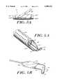
- FIG. 5Ais a perspective view of another embodiment of an active electrode in accordance with the present invention.
- FIG. 5Bis a perspective view of a further embodiment of an active electrode in accordance with the present invention.
- FIG. 6Ais a side view of an electrode assembly in accordance with the present invention with the assembly having an electrode shown in a first position;
- FIG. 6Bis a side view of the electrode assembly of FIG. 6B with the electrode shown in second position;
- FIG. 6Cis a top view of the electrode assembly of FIG. 6A;
- FIG. 7is a perspective view of an electrode assembly in accordance with the present invention, the assembly having a non-conductive body in the form of a surgical loop and a conductive coating;
- FIG. 8Ais a perspective view of another embodiment of an electrode assembly in accordance with the present invention, the assembly having a hemispherical non-conductive body and a conductive coating;
- FIG. 8Bis a perspective view of a further embodiment of an electrode assembly in accordance with the present invention, the assembly having a non-conductive body with a generally hemi-cylindrical shape and a conductive coating;
- FIG. 8Cis a perspective view of a still further embodiment of an electrode assembly in accordance with the present invention, the assembly having a generally spherical non-conductive body and a conductive coating;
- FIG. 9is a top view of a an electrode assembly in accordance with the present invention, the assembly having an electrode mechanically interlocked with a non-conductive body;
- FIG. 10is a cross-sectional view of the electrode assembly of FIG. 9 along lines 10--10;
- FIG. 11is a cross-sectional view of an alternative embodiment of the electrode assembly of FIG. 10;
- FIG. 12Ais a front view of a further embodiment of an electrode assembly in accordance with the present invention, the assembly having an electrode that is rotatable with respect to a non-conductive hood;
- FIG. 12Bis a side view of the electrode assembly of FIG. 12A.
- FIG. 12Cis a side view of an alternative embodiment of the electrode assembly of FIG. 12B.
- an electrosurgical instrument 10includes a selectively coated active electrode 12 for delivering electrical current to a treatment site of a patient.
- the instrumentis suitable for insertion into the patient in accordance with closed surgery (e.g., arthroscopic, endoscopic, hysteroscopic, urologic, resectoscopic and laparoscopic procedures) or open surgery.
- the illustrative instrument 10is a hysteroscope in which the active electrode 12 is intended for insertion into the uterine cavity of a female patient for treatment of various conditions. It will be appreciated however that various types of electrosurgical instruments can be used for other procedures while utilizing and achieving the advantages of the selectively coated electrode described herein.
- the instrument 10includes a proximal portion 14, including a handle 16 for user handling of the instrument in order to guide the electrode 12 into contact with the treatment site, and a forward portion 18.
- the forward portion 18includes an elongated probe 20 having a proximal end 22 adjacent to the handle 16 and a distal end 24 from which the active electrode 12 retractably extends.
- the electrode 12is capable of being moved along the longitudinal axis of the probe 20 so as to extend through an aperture 26 (FIG. 2) at the distal end 24 of the probe 20 to contact tissue or to be retracted into the end 24 of the probe 20 through the aperture 26.
- An actuator 28permits retraction and extension of the electrode 12 via a mechanical coupling within the probe 20.
- An optical path within the instrument 10extends between an eye piece 30 at the rearward portion 14 and a lens 32 at the distal end 24 of the probe 20.
- the optical pathpermits the surgeon to view the treatment site.
- a light delivery port 34permits light to be introduced into the optical path.
- the electrosurgical instrument 10is capable of delivering fluid to and collecting fluid from the treatment site.
- the instrument 10includes a fluid input port 36 which is adapted for coupling to an external fluid source 39.
- the fluid thus introduced into the instrument 10is directed toward the distal end 24 of the probe 20 via a first, inner fluid channel 38, where the fluid exits the instrument aperture 26.
- the first fluid channel 38is defined by an inner sheath 40.
- a second, outer fluid channel 42 between an outer sheath 44 of the probe 20 and the inner sheath 40serves to collect fluid from the treatment area.
- a fluid intakesuch as apertures 46 through the outer sheath 44, permit fluid collection.
- Fluid from the treatment areaflows through the second fluid channel 42 toward the proximal end 22 of the probe 20, where the fluid exits the instrument through a fluid output port 48.
- an end of the outer sheath 44extends beyond an end of the inner sheath 40.
- the inner sheath 40extends beyond the end of the outer sheath 44.
- An energy source 50such as a source of radio frequency (RF) energy, provides electrical energy for delivery by the active electrode 12 to the treatment site. More particularly, a control device 52 coupled between the energy source 50 and the instrument 10 permits conventional control of alternating current provided by the source 50, including the ability to turn the energy source on and off as a function of the position of the electrode 12 relative to the treatment site.
- Conductors 54 and 56carry the current from or to the energy source, and may be referred to as an active conductor 54 and a return conductor 56. In an exemplary embodiment, the current delivered to the treatment site ranges from 0.1 to 2.0 amps.
- the selectively coated electrode of the inventioncan be a monopolar device, with the return conductor 56 being coupled to a return electrode in the form of a ground pad 58 which is suitable for external attachment to a patient's skin.
- the return electrode 58contacts the patient's body at a remote location relative to the treatment site at which the active electrode 12 is located.
- the active conductor 54is coupled to the active electrode 12 through an electrical path within the probe 20.
- the outer sheath and/or inner sheathcan form a return electrode for the device.
- the outer sheath 44can have a coated portion 47 that is electrically insulated by the coating material and an exposed return electrode portion 49.
- the return electrode portioncan be formed as desired to obtain a desired amount of surface area for the return electrode of the device. This arrangement eliminates or supplements a return electrode in contact with the patient's body.
- the selectively coated electrode of the inventioncan be used with a delivery instrument other than the hysteroscope illustrated in FIG. 1.
- a delivery instrumentother than the hysteroscope illustrated in FIG. 1.
- the selectively coated electrodecan be used with other scope-like instruments, with or without modification of the electrode.
- the selectively coated electrode of the inventioncan be used in open surgical procedures without a scope-like delivery device.
- the active electrode 12includes a first portion 60 covered with a coating.
- a second, tissue-affecting portion 62 of the active electroderemains exposed.
- the tissue-affecting portion of the electrodeis understood to be the portion of the electrode from which current is delivered to tissue. This portion of the electrode is largely responsible for cutting and/or cauterizing tissue that it contacts.
- a frame 64 coupled to the active electrode 12provides a mechanism for mechanically supporting the electrode 12. Further, the frame 64 may be conductive and may provide a mechanism for coupling electrical energy from a source (not shown) to the tissue-affecting portion 62 of the electrode.
- the conductive frameshould be coated, at least in part, with an insulative coating to reduce energy dissipation in the surrounding isotonic solution.
- the frameis a hollow, non-conductive member having a conductive path therein to allow the electrosurgical generator to energize the active electrode.
- the electrode 12is substantially channel-shaped, with the tissue-affecting portion 62 terminating at a sharp, blade-like tip 63.
- the coating materialcan extend over virtually the entire surface of the electrode, except for the sharpened edge of the blade-like tip 63.
- the coatingeffectively insulates the covered first portion 60 of the active electrode, there is a parasitic capacitance formed on the covered first portion due to the coating.
- the insulative, or partially insulative, coatingacts as a dielectric between conductive isotonic solution and the first portion 60 of the electrode producing a capacitive effect.
- the parasitic capacitancehas a reactance associated therewith that forms a portion of the impedance through the solution and the coated first portion 60 of the active electrode. Preferably, this impedance is much greater than the impedance between the exposed tissue-affecting portion 62 of the active electrode and the solution or tissue.
- the impedance associated with the coated first portion 60 of the electrodeis at least one order of magnitude greater than the impedance of the desired current path from the tissue affecting portion 62 of the electrode to tissue and/or isotonic solution at the desired operating frequency of the RF generator.
- the reactance due to the parasitic capacitance of the coated first portion of the electrode, and therefore the impedanceis frequency dependent.
- impedancesare measured at the operating frequency of the RF energy source 50.
- the impedance through the coatingcan be chosen to be much greater than the impedance of the desired current path by adjusting the thickness of the coating material. To provide the preferred much greater impedance through the coated portion of the electrode for a given operating frequency, a coating thickness is selected to obtain the desired impedance value.
- the coating materialis an insulative or partly insulative material. It is understood that insulative, as used herein, is to be construed broadly.
- the coatingis a medical grade ceramic material, such as aluminum oxide.
- Other coating materialsinclude ceramics (e.g., glass, aluminum-silicate, alumina, or boron), non-conductive epoxy, ceramic adhesive, glass enamels, glass-filled polymers, polysulfones, polytetrafluoroethylene, polysiloxanes, silicones, polyetheretherketone, Parylene, and Kevlar. It will be appreciated by those of ordinary skill in the art that the thickness of the coating material can be readily varied.
- the thicknessis in the range of about 2 microns to about 150 microns.
- the ceramic coatingcan be applied by vacuum chamber deposition or by electrostatically spraying a ceramic material and curing the coating at a suitable temperature. Other coating techniques will be apparent to those having ordinary skill in the art.
- the electrodehas dual blade-like edges 63', with an insulative coating in the area between the edges.
- This dual-edged arrangementis well suited for certain procedures involving scraping of tissue.
- Many other electrode geometricsare also possible.
- the electrodesfurther may or may not have sharpened blade-like edges.
- An important feature of the inventionis to maximize the coated area of the electrode while minimizing the non-coated, tissue-affecting portion of the electrode.
- One of ordinary skill in the artwill appreciate that further alternative electrode geometries can be used without departing from the scope of the invention.
- the coating materialis semi-insulative.
- Suitable semi-insulative coatingsinclude those having an impedance greater than that of the exposed portion of the electrode, so as to provide a path of lower electrical resistance between the energy source and the exposed portion 62 as compared to the path between the energy-source and the coated portion 60.
- currentis directed toward the exposed tissue-contacting portion 62 of the electrode in order to enhance the electrosurgical effect of the device.
- This energy focusing aspect of the instrumentfurther serves to render the instrument suitable for use in an isotonic fluid medium by reducing the conductive surface area of the active electrode.
- a glow associated with the use of an energized electrode in an isotonic solutionis reduced. This enhances the field of vision of the surgeon when treating tissue with the electrode.
- the electrode 60is tungsten, but other biologically compatible materials having suitable conductivity and strength can be used. Examples of suitable materials include stainless steel, tungsten, titanium, platinum, silver, gold, brass, nickel-titanium alloys and other biocompatible metals.
- FIG. 4Ais another embodiment of a monopolar electrosurgical instrument having an active electrode 12" in the form of a loop 70 that extends from an inner sheath 40 that is disposed with an outer sheath as discussed in conjunction with FIG. 2A.
- the loop 70includes a coated portion 72 and an exposed tissue-affecting portion 74.
- the tissue-affecting portion 74cuts and/or cauterizes tissue under the control of an operator, such as a surgeon.
- Current densityis maximized at the tissue-affecting portion 74 of the loop so that current dissipation in isotonic solution and non-target tissue is minimized.
- FIG. 4Bis a further embodiment of an active electrode 12" in the form of a loop 70 having a coated first portion 72 and an exposed tissue-affecting portion 74.
- the loop 70extends from a frame 64 that supports the loop during use.
- a return electrode 76is electrically insulated from the loop and is disposed on the frame to provide a return path for current from the loop.
- FIG. 4Cillustrates an example of a coating pattern in which virtually the entire loop is coated except for a rear-facing circumferential portion 74.
- Other coating patternsmay be used as well. For example, the entire loop can be coated, except for an uncoated distal-most end.
- FIG. 5Ashows another embodiment of an active electrode 100 having an insulative coating 102 disposed on a portion of an outer surface 104 of the electrode so as to form a coated portion 106 and an non-coated exposed portion 108. It is understood that the apportionment between the coated portion 106 and the exposed portion 108 can vary. In general, the exposed portion 108 of the electrode should be minimized to reduce energy dissipation into a conductive solution while providing a desired surface area for contact between the electrode and the tissue.
- the electrode 100can be formed in a variety of geometries including cylindrical, spherical, arcuate, convex, and hemispherical.
- the electrode 100is generally cylindrical with opposite first and second ends 110,112.
- a frame 114includes a first structural member 116a coupled to the first end 110 of the electrode and a second structural member 116b coupled to the second end 112.
- the structural members 116are affixed to the first and second ends 110,112 such that the electrode 100 remains in a predetermined position with respect to the structural members 116a,b. It is understood that the frame 114 can be affixed to the electrode 100 at a range of angles depending upon the particular orientation of the target tissue in relation to the exposed portion 108 of the electrode.
- FIG. 5Bshows an alternative embodiment of the electrode 100 of FIG. 5A wherein the electrode 100' has a generally spherical shape.
- the electrode 100'has a portion 106' coated with an insulative material and an exposed portion 108' for treating tissue.
- an electrode assembly 200is shown having an electrode 202 which is movable between a first position (FIG. 6A) and a second position (FIG. 6B).
- the electrode 202has a portion 204 coated with an insulative material and an exposed portion 206 adapted for treating tissue.
- a frame 208includes first and second structural members 210a,b pivotally coupled to opposite locations on the electrode 202 via first and second coupling mechanisms 212a,b.
- the coupling mechanisms 212can be formed from a variety of mechanisms that allow selective movement of the electrode 202 with respect to the frame 208. Exemplary mechanisms include positive and negative surface features, hinges and pivoting structures. It is understood that the electrode 202 and/or the frame 208 can provide the pivoting action of the electrode assembly.
- the coupling mechanisms 212a,binclude an arcuate groove 214 formed in the electrode 202 into which distal tips 216a,b of the structural members 210a,b are inserted. Electrical contact between the distal tips 216a,b and the electrode is maintained to provide a constant flow of energy to the electrode.
- the electrode 202rotates between the first position (FIG. 6A) and the second position (FIG.
- the electrode 202can be biased to the first (or second) position with a biasing member 218, such as a spring.
- the amount that the electrode 202 can rotate with respect to the frame 208can range from about fifteen degrees to about ninety degrees.
- the pivotal feature of the electrode 202allows a surgeon to control the position of the exposed portion 206 of the electrode with respect to tissue 220. That is, with the application of pressure generally along a longitudinal axis 222 of the structural members 210, the exposed portion 206 of the electrode rotates so as to increase the contact area between the tissue 220 and the exposed portion 206 of the electrode.
- the pivotal feature of the electrode assembly 200enhances the ability of a surgeon to selectively treat tissue with the exposed portion 206 of the electrode.
- the pivoting electrode assemblyis well-suited for treating endometrium tissue with a dabbing type motion.
- FIG. 7illustrates another embodiment of an electrode assembly 300 in accordance with the present invention.
- the assembly 300includes an electrode formed from a coating 304, which is made from a conductive material, disposed on a body 306, which is formed from a non-conductive material. Coupled to the conductive coating 304 are conductors 308a,b extending along a frame 310 to an electrosurgical RF energy source 50 (FIG. 1).
- the electrode assembly 300can be formed in a variety of configurations such as surgical loops, spheres, cylinders, and hemispheres.
- the electrode assembly 300including the non-conductive body 306 and conductive coating 304, is configured as a surgical loop.
- the conductive coating 304is selectively applied to the body 306 so as to provide a tissue-cutting electrode that is effective to minimize energy dissipation in an isotonic solution.
- the conductive coating 304should be of sufficient size to conduct operational current levels without excessive heating of the coating 304 and/or the adjacent body 306.
- An exemplary thickness range for the coating 304is from about 0.001 inch to about 0.100 inch. It is understood that a relatively thick coating increases durability.
- the non-conductive body 306can be formed from suitable materials that are sufficiently strong and rigid to resist breaking as pressure is applied to the electrode assembly during use.
- suitable materials for the non-conductive bodyinclude ceramics (e.g., glass, aluminum-silicate, alumina, or boron), non-conductive epoxy, ceramic adhesive, glass enamels, glass-filled polymers, polysulfones, polytetrafluoroethylene, polysiloxanes, silicones, polyetheretherketone, Parylene, and Kevlar.
- the conductive coating 304is formed from a material that provides a suitable circuit path for the applied electrosurgical energy.
- the conductive coatingcan be formed from a variety of materials including metals such as stainless steel, tungsten, titanium, platinum, silver, gold, brass, nickel-titanium alloys and other biocompatible metals.
- an electrode assembly 400has an electrode 402 formed from a conductive coating 404 which covers a portion of a body 406 formed from a non-conductive material.
- the non-conductive body 406has a hemispherical shape with the conductive coating 404 formed on a planar surface 408 of the body.
- the hemispherical geometry of the electrode assembly 400enhances the visual field of the surgeon by reducing the overall size of the electrode assembly as compared with spherical electrodes and the like.
- FIG. 8Bshows an alternate embodiment of an electrode assembly 400' having a cylindrical geometry with a conductive coating 404' disposed on a non-conductive body 406'.
- FIG. 8Cshows an electrode assembly 400" having a generally spherical shape with a conductive coating 404" covering a portion of a non-conductive body 406".
- the coatingranges in thickness from about 0.001 inch to about 0.100 inch.
- the conductive coatings 404are coupled to an electrosurgical RF generator 50 like that shown in FIG. 1 via conductors 308 like those shown in FIG. 7.
- an electrode assemblyincludes an active electrode which is mechanically interlocked with a non-conductive body or hood.
- the electrode and the hoodare disposed in proximity with each other so as to form a gap.
- the hood and gapcombine to provide the desired insulative effect that is effective to minimize current dissipation from a portion of the electrode that does not contact tissue.
- FIGS. 9-10show an electrode assembly 500 including an electrode 502 for treating tissue and a non-conductive portion or body 504 for reducing energy dissipation into an isotonic solution.
- the non-conductive body 504is mechanically coupled to the electrode 502 so as to form a gap 506.
- mechanical coupling or interlockingrefers to structural features that position the non-conductive body 504 with respect to the electrode 502. That is, the non-conductive body 504 does not adhere to the electrode 502. Further, it is understood that the gap 506 can vary in distance from substantially zero to about 0.08 inch.
- the mechanism used to couple the body 504 to the electrode 502can be formed from a variety of structures.
- Exemplary mechanismsinclude complementary surface features, interference engagements, snap-fits, adhesives, insert molding, and heat shrinking.
- the mechanical coupling mechanismshould retain the non-conductive body 504 in close proximity with an outer surface 508 of the electrode 502 so as to maintain the gap 506.
- the gap 506 between the electrode 502 and the body 504can be continuous or discontinuous and uniform or non-uniform.
- the electrode and/or the non-conductive bodymay have an irregular surface contour which includes grooves, dimples and other surface features that generate a non-uniform gap.
- the non-conductive body 504includes first and second surface features 510a,b in the form of protrusions that are sized to fit within complementary channels 512a,b formed in the outer surface 508 of the electrode.
- the protrusions 510securely engage the body 504 to the electrode 502 and form the gap 506 therebetween.
- the electrode assembly 500can be coupled to a frame 514 such that the electrode assembly is in a fixed position (FIGS. 9-10), or so that the electrode assembly can rotate with respect to the frame 514 (FIG. 11) as pressure is applied to maintain contact between the frame and the electrode. It is further understood that energy flows to the electrode 502 via conductors (not shown) that extend along the frame 514 and axle to a source of electrosurgical energy.
- FIG. 11shows an alternative embodiment of an electrode assembly 500' having an electrode 502' and a non-conductive body 504' having a member 516 protruding inwardly to a central portion of the electrode 502'.
- the protruding member 516is effective to securely engage the non-conductive body 504' to the electrode 502' by means of mechanical interference.
- a surgeonpositions the electrode 502 in contact with tissue as desired. Although some saline or other isotonic fluid may enter the gap 506, the fluid is quickly transformed to steam due to the high temperature of the electrode 502. Relatively little energy will be dissipated in the steam as compared with isotonic solution.
- tissue debrissuch as desiccated tissue, which enters the gap 506 is generally insulative.
- the non-conductive body 504provides the desired insulative effect without intimate contact with the electrode.
- the gap 506also provides space for thermal expansion of the metallic electrode 502 as the temperature of the electrode increases during use.
- the non-conductive body 504can be sized to accommodate thermal expansion of the electrode to achieve a desired distance for the gap 506.
- the non-conductive body 504can be formed so as to be slightly undersized upon full thermal expansion of the electrode 502 so as to capture the electrode during use. It is understood that the apportionment of the electrode assembly 500 between the electrode 502 and the non-conductive body 504 can vary depending upon the requirements of a particular application.
- the electrode 502should have a geometry adapted for treating a selected area of tissue at a desired energy level.
- Exemplary materials for the non-conductive body 504include ceramics (e. g., glass, aluminum-silicate, alumina, or boron), non-conductive epoxy, ceramic adhesive, glass enamels, glass-filled polymers, polysulfones, polytetrafluoroethylene, polysiloxanes, silicones, polyetheretherketone, Parylene, and Kevlar.
- FIGS. 12A-Bshow an electrode assembly 600 having an electrode 602 that is rotatable with respect to a non-conductive hood 604 and a frame 606.
- the hood 604is affixed to the frame 606 while the electrode 602 is rotatably secured to the frame 606.
- the electrode 602is electrically coupled to an axle portion 607 of the frame to provide a path for RF energy to flow to the electrode.
- a gap 608is formed between an outer surface 610 of the electrode and an inner surface 612 of the hood.
- the gap 608 and non-conductive hood 604combine to provide an insulative effect for a covered portion of the electrode 602 as the electrode assembly 600 is rolled along a tissue site in an isotonic solution environment.
- FIG. 12Cshows an alternative embodiment of an electrode assembly 600' having a hood 604' with a lateral surface 614 that forms an obtuse angle A with respect to the outer surface 610' of the electrode 602'.
- the angle Acan vary from about ninety degrees to about 180 degrees with respect to a tangent 616 to the electrode 602'.
- the gap 608'can also narrow proximate the lateral surface 614, such as to a distance between about 0.001 inch to about 0.010 inch.
- the lateral surface 614 of the hoodis effective to scrape off tissue adhering to the electrode as it rotates.
- the dimensions of the electrode assembly 600 componentscan vary.
- the electrode 602has a diameter in the range from about 2 to about 5 millimeters and the hood 604 has a thickness in the range from about 0.01 inch to about 0.08 inch.
- the amount of uncovered electrodecan vary depending upon the particular application. In general, the uncovered portion of the electrode surface area can range from ten to ninety percent.
- the inventionenables a monopolar electrosurgical tool (i.e., one that utilizes a remote ground pad to complete the electrical circuit) to be used in an environment that includes an isotonic fluid.
- monopolar electrosurgical devicesdeliver current to tissue in a non-focused manner such that the current is passed to target tissue as well as other non-target tissue in the vicinity of the electrode.
- thiscan present a problem in closed surgical procedures that involve the use of a fluid medium.
- the tendency of conventional monopolar tools to dissipate currentgenerally precludes their use in an isotonic fluid medium.
- the present inventionwhich permits the focused delivery of electrosurgical energy, with little or no current dissipation outside of target tissue, enables the use of a monopolar electrosurgical instrument in an isotonic fluid medium.
- an isotonic fluid mediumis understood to be one having an osmolarity in the range of about 260 or 295 milliosmols.
- suitable isotonic fluidsare saline and Ringer's lactate.
Landscapes
- Health & Medical Sciences (AREA)
- Surgery (AREA)
- Engineering & Computer Science (AREA)
- Life Sciences & Earth Sciences (AREA)
- Biomedical Technology (AREA)
- Otolaryngology (AREA)
- Nuclear Medicine, Radiotherapy & Molecular Imaging (AREA)
- Plasma & Fusion (AREA)
- Physics & Mathematics (AREA)
- Heart & Thoracic Surgery (AREA)
- Medical Informatics (AREA)
- Molecular Biology (AREA)
- Animal Behavior & Ethology (AREA)
- General Health & Medical Sciences (AREA)
- Public Health (AREA)
- Veterinary Medicine (AREA)
- Surgical Instruments (AREA)
Abstract
Description
Claims (22)
Priority Applications (3)
| Application Number | Priority Date | Filing Date | Title |
|---|---|---|---|
| US09/092,694US6080152A (en) | 1998-06-05 | 1998-06-05 | Electrosurgical instrument |
| PCT/US1999/012305WO1999062414A1 (en) | 1998-06-05 | 1999-06-03 | Electrosurgical instrument |
| AU45455/99AAU4545599A (en) | 1998-06-05 | 1999-06-03 | Electrosurgical instrument |
Applications Claiming Priority (1)
| Application Number | Priority Date | Filing Date | Title |
|---|---|---|---|
| US09/092,694US6080152A (en) | 1998-06-05 | 1998-06-05 | Electrosurgical instrument |
Publications (1)
| Publication Number | Publication Date |
|---|---|
| US6080152Atrue US6080152A (en) | 2000-06-27 |
Family
ID=22234597
Family Applications (1)
| Application Number | Title | Priority Date | Filing Date |
|---|---|---|---|
| US09/092,694Expired - LifetimeUS6080152A (en) | 1998-06-05 | 1998-06-05 | Electrosurgical instrument |
Country Status (3)
| Country | Link |
|---|---|
| US (1) | US6080152A (en) |
| AU (1) | AU4545599A (en) |
| WO (1) | WO1999062414A1 (en) |
Cited By (67)
| Publication number | Priority date | Publication date | Assignee | Title |
|---|---|---|---|---|
| US6245069B1 (en)* | 1995-12-22 | 2001-06-12 | Karl Storz Gmbh & Co. Kg | Cutting loop electrode for high-frequency instrument |
| US6432104B1 (en)* | 1998-04-15 | 2002-08-13 | Scimed Life Systems, Inc. | Electro-cautery catherer |
| EP1388324A1 (en)* | 2002-08-05 | 2004-02-11 | Jon C. Garito | Adenoid curette electrosurgical probe |
| US20040143258A1 (en)* | 1999-08-10 | 2004-07-22 | Biosense Webster, Inc. | Irrigation probe for ablation during open heart surgery |
| US20040152977A1 (en)* | 2000-04-25 | 2004-08-05 | Impres Medical, Inc. | Method and apparatus for creating intrauterine adhesions |
| US20040162554A1 (en)* | 2002-12-20 | 2004-08-19 | Manoa Medical, Inc., A Delaware Corporation | Systems and methods for cutting tissue |
| US20040186368A1 (en)* | 2003-03-21 | 2004-09-23 | Scimed Life Systems, Inc. | Systems and methods for internal tissue penetration |
| US20040254571A1 (en)* | 2003-01-31 | 2004-12-16 | Kobi Iki | Cartilage treatment probe |
| US20040255958A1 (en)* | 1999-02-01 | 2004-12-23 | Adiana, Inc. | Method and apparatus for tubal occlusion |
| US20050033163A1 (en)* | 2001-04-24 | 2005-02-10 | Impres Medical, Inc. | Intrauterine implant and methods of use |
| US20050031662A1 (en)* | 2001-04-24 | 2005-02-10 | Impres Medical, Inc. | Bioreactive methods and devices for treating uterine bleeding |
| US20050245925A1 (en)* | 2003-01-31 | 2005-11-03 | Kobi Iki | Cartilage treatment probe |
| US20060064113A1 (en)* | 2004-09-17 | 2006-03-23 | Nakao Naomi L | Endoscopic mucosal resection method and associated instrument |
| US20080065065A1 (en)* | 2004-03-19 | 2008-03-13 | Sutter Medizintechnik Gmbh | Bipolar coagulation electrode |
| US20080222498A1 (en)* | 2006-10-27 | 2008-09-11 | Sunplus Technology Co., Ltd. | Sequential decoding method and apparatus thereof |
| US20090036840A1 (en)* | 2006-11-22 | 2009-02-05 | Cytyc Corporation | Atraumatic ball tip and side wall opening |
| US20090125023A1 (en)* | 2007-11-13 | 2009-05-14 | Cytyc Corporation | Electrosurgical Instrument |
| US7582085B2 (en) | 2002-05-23 | 2009-09-01 | Cytyc Corporation | Catheter placement detection system and operator interface |
| DE102008020967A1 (en)* | 2008-04-25 | 2009-10-29 | Fehling Ag | Operational myectomy instrument for treatment of hypertrophic obstructive cardio myopathy of sub-aortic septum, has cutting unit for epispastic cutting, and light mechanism integrated in arm of handle for illuminating area of cutting unit |
| US20090277463A1 (en)* | 1999-08-23 | 2009-11-12 | Conceptus, Inc., A California Corporation | Deployment Actuation System for Intrafallopian Contraception |
| US20100063360A1 (en)* | 2006-11-28 | 2010-03-11 | Adiana, Inc. | Side-arm Port Introducer |
| US20100217255A1 (en)* | 2009-02-23 | 2010-08-26 | Salient Surgical Technologies, Inc. | Fluid-Assisted Electrosurgical Device and Methods of Use Thereof |
| US7905880B2 (en) | 1997-06-05 | 2011-03-15 | Cytyc Corporation | Method and apparatus for tubal occlusion |
| US7921848B2 (en) | 1995-06-07 | 2011-04-12 | Conceptus, Inc. | Contraceptive transcervical fallopian tube occlusion devices and methods |
| US20110180073A1 (en)* | 2010-01-22 | 2011-07-28 | David Callaghan | Sterilization Device and Method |
| US20110220120A1 (en)* | 2006-10-12 | 2011-09-15 | Frigstad John R | Method and Apparatus For Occluding A Lumen |
| US8048101B2 (en) | 2004-02-25 | 2011-11-01 | Femasys Inc. | Methods and devices for conduit occlusion |
| US8048086B2 (en) | 2004-02-25 | 2011-11-01 | Femasys Inc. | Methods and devices for conduit occlusion |
| US8052669B2 (en) | 2004-02-25 | 2011-11-08 | Femasys Inc. | Methods and devices for delivery of compositions to conduits |
| US8066007B2 (en) | 1995-06-07 | 2011-11-29 | Conceptus, Inc. | Contraceptive transcervical fallopian tube occlusion devices and their delivery |
| US8303582B2 (en) | 2008-09-15 | 2012-11-06 | Tyco Healthcare Group Lp | Electrosurgical instrument having a coated electrode utilizing an atomic layer deposition technique |
| US8409196B2 (en) | 1998-04-15 | 2013-04-02 | Boston Scientific Scimed, Inc. | Electro-cautery catheter |
| US8550086B2 (en) | 2010-05-04 | 2013-10-08 | Hologic, Inc. | Radiopaque implant |
| US20130317493A1 (en)* | 2000-08-01 | 2013-11-28 | Arqos Surgical, Inc. | Voltage threshold ablation apparatus |
| JP2014004368A (en)* | 2012-06-25 | 2014-01-16 | Biosense Webster (Israel) Ltd | Irrigated electrode with enhanced heat conduction |
| US20140039493A1 (en)* | 2010-06-30 | 2014-02-06 | Medtronic Advanced Energy Llc | Electrosurgical Devices and Methods of Use Thereof |
| US8702727B1 (en) | 1999-02-01 | 2014-04-22 | Hologic, Inc. | Delivery catheter with implant ejection mechanism |
| CN104224316A (en)* | 2013-06-24 | 2014-12-24 | 佳乐医疗设备有限公司 | Electrosurgical electrode |
| US9238127B2 (en) | 2004-02-25 | 2016-01-19 | Femasys Inc. | Methods and devices for delivering to conduit |
| US9277954B2 (en) | 2011-03-21 | 2016-03-08 | Arqos Surgical, Inc. | Medical ablation system and method of use |
| US20160089199A1 (en)* | 2014-09-25 | 2016-03-31 | Covidien Lp | Single-handed operable surgical instrument including loop electrode with integrated pad electrode |
| US9554826B2 (en) | 2008-10-03 | 2017-01-31 | Femasys, Inc. | Contrast agent injection system for sonographic imaging |
| GB2551117A (en)* | 2016-05-31 | 2017-12-13 | Creo Medical Ltd | Electrosurgical apparatus and method |
| US20180228530A1 (en)* | 2017-02-16 | 2018-08-16 | Ethicon Llc | Electrosurgical instrument with telescoping suction port and debris cleaner |
| US10070888B2 (en) | 2008-10-03 | 2018-09-11 | Femasys, Inc. | Methods and devices for sonographic imaging |
| US10492849B2 (en) | 2013-03-15 | 2019-12-03 | Cynosure, Llc | Surgical instruments and systems with multimodes of treatments and electrosurgical operation |
| US10603117B2 (en) | 2017-06-28 | 2020-03-31 | Ethicon Llc | Articulation state detection mechanisms |
| US10751109B2 (en) | 2014-12-22 | 2020-08-25 | Ethicon Llc | High power battery powered RF amplifier topology |
| US10751117B2 (en) | 2016-09-23 | 2020-08-25 | Ethicon Llc | Electrosurgical instrument with fluid diverter |
| US10779876B2 (en) | 2011-10-24 | 2020-09-22 | Ethicon Llc | Battery powered surgical instrument |
| US10799284B2 (en) | 2017-03-15 | 2020-10-13 | Ethicon Llc | Electrosurgical instrument with textured jaws |
| US10856934B2 (en) | 2016-04-29 | 2020-12-08 | Ethicon Llc | Electrosurgical instrument with electrically conductive gap setting and tissue engaging members |
| US10959771B2 (en) | 2015-10-16 | 2021-03-30 | Ethicon Llc | Suction and irrigation sealing grasper |
| US10959806B2 (en) | 2015-12-30 | 2021-03-30 | Ethicon Llc | Energized medical device with reusable handle |
| US10987156B2 (en) | 2016-04-29 | 2021-04-27 | Ethicon Llc | Electrosurgical instrument with electrically conductive gap setting member and electrically insulative tissue engaging members |
| US11033323B2 (en) | 2017-09-29 | 2021-06-15 | Cilag Gmbh International | Systems and methods for managing fluid and suction in electrosurgical systems |
| US11090103B2 (en) | 2010-05-21 | 2021-08-17 | Cilag Gmbh International | Medical device |
| US11246644B2 (en) | 2018-04-05 | 2022-02-15 | Covidien Lp | Surface ablation using bipolar RF electrode |
| US11484358B2 (en) | 2017-09-29 | 2022-11-01 | Cilag Gmbh International | Flexible electrosurgical instrument |
| US11490951B2 (en) | 2017-09-29 | 2022-11-08 | Cilag Gmbh International | Saline contact with electrodes |
| US11497546B2 (en) | 2017-03-31 | 2022-11-15 | Cilag Gmbh International | Area ratios of patterned coatings on RF electrodes to reduce sticking |
| USD1005484S1 (en) | 2019-07-19 | 2023-11-21 | Cynosure, Llc | Handheld medical instrument and docking base |
| US11819259B2 (en) | 2018-02-07 | 2023-11-21 | Cynosure, Inc. | Methods and apparatus for controlled RF treatments and RF generator system |
| US11883089B2 (en) | 2016-11-14 | 2024-01-30 | Medtronic, Inc. | Controlled optical properties vitreous enamel composition for electrosurgical tool |
| US11957342B2 (en) | 2021-11-01 | 2024-04-16 | Cilag Gmbh International | Devices, systems, and methods for detecting tissue and foreign objects during a surgical operation |
| US12121286B2 (en) | 2020-07-23 | 2024-10-22 | Covidien Lp | Devices and methods for shallow depth ablation |
| US12171463B2 (en) | 2008-10-03 | 2024-12-24 | Femasys Inc. | Contrast agent generation and injection system for sonographic imaging |
Families Citing this family (5)
| Publication number | Priority date | Publication date | Assignee | Title |
|---|---|---|---|---|
| US7608073B2 (en) | 2004-07-09 | 2009-10-27 | Tyco Healthcare Group Lp | Energy based partial circumferential hemorrhoid repair device |
| GB2460242A (en)* | 2008-05-20 | 2009-11-25 | Gyrus Medical Ltd | Morcellating laparoscopic instrument with bipolar electrodes and double skin wall. |
| US10792096B2 (en) | 2010-11-08 | 2020-10-06 | Baylis Medical Company Inc. | Medical device having a support structure |
| US11937873B2 (en) | 2013-03-12 | 2024-03-26 | Boston Scientific Medical Device Limited | Electrosurgical device having a lumen |
| EP2968846B1 (en)* | 2013-03-12 | 2022-05-04 | Baylis Medical Company Inc. | Medical device having a support structure |
Citations (50)
| Publication number | Priority date | Publication date | Assignee | Title |
|---|---|---|---|---|
| US33925A (en)* | 1861-12-17 | Improvement in fastenings for shoulder-straps | ||
| GB626911A (en)* | 1948-01-12 | 1949-07-22 | Eugenie Leibowitsch | Improvements in electro-medical apparatus |
| US4202338A (en)* | 1977-11-18 | 1980-05-13 | Richard Wolf Gmbh | Device for removing excrescences and polyps |
| US4311143A (en)* | 1978-10-12 | 1982-01-19 | Olympus Optical Co., Ltd. | Apparatus for resecting tissue inside the body cavity utilizing high-frequency currents |
| US4362160A (en)* | 1979-07-24 | 1982-12-07 | Richard Wolf Gmbh | Endoscopes |
| US4493320A (en)* | 1982-04-02 | 1985-01-15 | Treat Michael R | Bipolar electrocautery surgical snare |
| US4532924A (en)* | 1980-05-13 | 1985-08-06 | American Hospital Supply Corporation | Multipolar electrosurgical device and method |
| US4657017A (en)* | 1983-12-01 | 1987-04-14 | Nauchno-Isledovatelsky Institute Obshei I Neotlozhnoi Khirugii | Electrosurgical instrument |
| US4802476A (en)* | 1987-06-01 | 1989-02-07 | Everest Medical Corporation | Electro-surgical instrument |
| US4905691A (en)* | 1989-04-17 | 1990-03-06 | Everest Medical Corporation | Polypectome snare with bipolar electrodes |
| US4917082A (en)* | 1988-06-02 | 1990-04-17 | Circon Corporation | Resectoscope electrode |
| US4920978A (en)* | 1988-08-31 | 1990-05-01 | Triangle Research And Development Corporation | Method and apparatus for the endoscopic treatment of deep tumors using RF hyperthermia |
| US5078716A (en)* | 1990-05-11 | 1992-01-07 | Doll Larry F | Electrosurgical apparatus for resecting abnormal protruding growth |
| US5080660A (en)* | 1990-05-11 | 1992-01-14 | Applied Urology, Inc. | Electrosurgical electrode |
| USRE33925E (en) | 1984-05-22 | 1992-05-12 | Cordis Corporation | Electrosurgical catheter aned method for vascular applications |
| US5158561A (en)* | 1992-03-23 | 1992-10-27 | Everest Medical Corporation | Monopolar polypectomy snare with coagulation electrode |
| US5158087A (en)* | 1992-01-31 | 1992-10-27 | Hewlett-Packard Company | Differential temperature measurement for ultrasound transducer thermal control |
| US5196011A (en)* | 1990-10-15 | 1993-03-23 | Olympus Winter & Ibe Gmbh | Cutting electrode for medical resectoscope |
| US5269782A (en)* | 1991-04-22 | 1993-12-14 | Select Medizin-Technik Hermann Sutter Gmbh | Bipolar medical coagulation and cauterizing instrument |
| US5290282A (en)* | 1992-06-26 | 1994-03-01 | Christopher D. Casscells | Coagulating cannula |
| US5312327A (en)* | 1992-10-09 | 1994-05-17 | Symbiosis Corporation | Cautery override safety systems endoscopic electrosurgical suction-irrigation instrument |
| US5318564A (en)* | 1992-05-01 | 1994-06-07 | Hemostatic Surgery Corporation | Bipolar surgical snare and methods of use |
| US5324288A (en)* | 1991-04-30 | 1994-06-28 | Utah Medical Products, Inc. | Electrosurgical loop with a depth gauge |
| US5324289A (en)* | 1991-06-07 | 1994-06-28 | Hemostatic Surgery Corporation | Hemostatic bi-polar electrosurgical cutting apparatus and methods of use |
| US5342358A (en)* | 1993-01-12 | 1994-08-30 | S.L.T. Japan Co., Ltd. | Apparatus for operation by laser energy |
| US5376087A (en)* | 1992-08-21 | 1994-12-27 | Habley Medical Technology Corporation | Multiple function cauterizing instrument |
| US5395363A (en)* | 1993-06-29 | 1995-03-07 | Utah Medical Products | Diathermy coagulation and ablation apparatus and method |
| US5396900A (en)* | 1991-04-04 | 1995-03-14 | Symbiosis Corporation | Endoscopic end effectors constructed from a combination of conductive and non-conductive materials and useful for selective endoscopic cautery |
| US5403312A (en)* | 1993-07-22 | 1995-04-04 | Ethicon, Inc. | Electrosurgical hemostatic device |
| US5423813A (en)* | 1993-03-18 | 1995-06-13 | Coopersurgical | Resectoscope and electrode assembly |
| US5437665A (en)* | 1993-10-12 | 1995-08-01 | Munro; Malcolm G. | Electrosurgical loop electrode instrument for laparoscopic surgery |
| US5456689A (en)* | 1993-10-13 | 1995-10-10 | Arnold J. Kresch | Method and device for tissue resection |
| US5462545A (en)* | 1994-01-31 | 1995-10-31 | New England Medical Center Hospitals, Inc. | Catheter electrodes |
| US5484435A (en)* | 1992-01-15 | 1996-01-16 | Conmed Corporation | Bipolar electrosurgical instrument for use in minimally invasive internal surgical procedures |
| US5486173A (en)* | 1993-12-08 | 1996-01-23 | Vancaillie; Thierry G. | Self-guiding electrode and cutting tip for tissue resection |
| US5531676A (en)* | 1992-08-12 | 1996-07-02 | Vidamed, Inc. | Medical probe device and method |
| US5542945A (en)* | 1993-10-05 | 1996-08-06 | Delma Elektro-U. Medizinische Apparatebau Gesellschaft Mbh | Electro-surgical radio-frequency instrument |
| US5558672A (en)* | 1994-06-24 | 1996-09-24 | Vidacare, Inc. | Thin layer ablation apparatus |
| US5569244A (en)* | 1995-04-20 | 1996-10-29 | Symbiosis Corporation | Loop electrodes for electrocautery probes for use with a resectoscope |
| US5599345A (en)* | 1993-11-08 | 1997-02-04 | Zomed International, Inc. | RF treatment apparatus |
| US5599295A (en)* | 1992-08-12 | 1997-02-04 | Vidamed, Inc. | Medical probe apparatus with enhanced RF, resistance heating, and microwave ablation capabilities |
| US5634924A (en)* | 1995-08-28 | 1997-06-03 | Symbiosis Corporation | Bipolar roller electrodes and electrocautery probes for use with a resectoscope |
| US5697909A (en)* | 1992-01-07 | 1997-12-16 | Arthrocare Corporation | Methods and apparatus for surgical cutting |
| US5697882A (en)* | 1992-01-07 | 1997-12-16 | Arthrocare Corporation | System and method for electrosurgical cutting and ablation |
| US5697536A (en)* | 1992-01-07 | 1997-12-16 | Arthrocare Corporation | System and method for electrosurgical cutting and ablation |
| US5810764A (en)* | 1992-01-07 | 1998-09-22 | Arthrocare Corporation | Resecting loop electrode and method for electrosurgical cutting and ablation |
| US5843019A (en)* | 1992-01-07 | 1998-12-01 | Arthrocare Corporation | Shaped electrodes and methods for electrosurgical cutting and ablation |
| US5891095A (en)* | 1993-05-10 | 1999-04-06 | Arthrocare Corporation | Electrosurgical treatment of tissue in electrically conductive fluid |
| US5902272A (en)* | 1992-01-07 | 1999-05-11 | Arthrocare Corporation | Planar ablation probe and method for electrosurgical cutting and ablation |
| US5925040A (en)* | 1997-06-18 | 1999-07-20 | Medical Scientific, Inc. | Electrosurgical instrument having a segmented roller electrode |
- 1998
- 1998-06-05USUS09/092,694patent/US6080152A/ennot_activeExpired - Lifetime
- 1999
- 1999-06-03AUAU45455/99Apatent/AU4545599A/ennot_activeAbandoned
- 1999-06-03WOPCT/US1999/012305patent/WO1999062414A1/enactiveApplication Filing
Patent Citations (57)
| Publication number | Priority date | Publication date | Assignee | Title |
|---|---|---|---|---|
| US33925A (en)* | 1861-12-17 | Improvement in fastenings for shoulder-straps | ||
| GB626911A (en)* | 1948-01-12 | 1949-07-22 | Eugenie Leibowitsch | Improvements in electro-medical apparatus |
| US4202338A (en)* | 1977-11-18 | 1980-05-13 | Richard Wolf Gmbh | Device for removing excrescences and polyps |
| US4311143A (en)* | 1978-10-12 | 1982-01-19 | Olympus Optical Co., Ltd. | Apparatus for resecting tissue inside the body cavity utilizing high-frequency currents |
| US4362160A (en)* | 1979-07-24 | 1982-12-07 | Richard Wolf Gmbh | Endoscopes |
| US4532924A (en)* | 1980-05-13 | 1985-08-06 | American Hospital Supply Corporation | Multipolar electrosurgical device and method |
| US4493320A (en)* | 1982-04-02 | 1985-01-15 | Treat Michael R | Bipolar electrocautery surgical snare |
| US4657017A (en)* | 1983-12-01 | 1987-04-14 | Nauchno-Isledovatelsky Institute Obshei I Neotlozhnoi Khirugii | Electrosurgical instrument |
| USRE33925E (en) | 1984-05-22 | 1992-05-12 | Cordis Corporation | Electrosurgical catheter aned method for vascular applications |
| US4802476A (en)* | 1987-06-01 | 1989-02-07 | Everest Medical Corporation | Electro-surgical instrument |
| US4917082A (en)* | 1988-06-02 | 1990-04-17 | Circon Corporation | Resectoscope electrode |
| US4920978A (en)* | 1988-08-31 | 1990-05-01 | Triangle Research And Development Corporation | Method and apparatus for the endoscopic treatment of deep tumors using RF hyperthermia |
| US4905691A (en)* | 1989-04-17 | 1990-03-06 | Everest Medical Corporation | Polypectome snare with bipolar electrodes |
| US5078716A (en)* | 1990-05-11 | 1992-01-07 | Doll Larry F | Electrosurgical apparatus for resecting abnormal protruding growth |
| US5080660A (en)* | 1990-05-11 | 1992-01-14 | Applied Urology, Inc. | Electrosurgical electrode |
| US5196011A (en)* | 1990-10-15 | 1993-03-23 | Olympus Winter & Ibe Gmbh | Cutting electrode for medical resectoscope |
| US5396900A (en)* | 1991-04-04 | 1995-03-14 | Symbiosis Corporation | Endoscopic end effectors constructed from a combination of conductive and non-conductive materials and useful for selective endoscopic cautery |
| US5269782A (en)* | 1991-04-22 | 1993-12-14 | Select Medizin-Technik Hermann Sutter Gmbh | Bipolar medical coagulation and cauterizing instrument |
| US5324288A (en)* | 1991-04-30 | 1994-06-28 | Utah Medical Products, Inc. | Electrosurgical loop with a depth gauge |
| US5330471A (en)* | 1991-06-07 | 1994-07-19 | Hemostatic Surgery Corporation | Bi-polar electrosurgical endoscopic instruments and methods of use |
| US5324289A (en)* | 1991-06-07 | 1994-06-28 | Hemostatic Surgery Corporation | Hemostatic bi-polar electrosurgical cutting apparatus and methods of use |
| US5697281A (en)* | 1991-10-09 | 1997-12-16 | Arthrocare Corporation | System and method for electrosurgical cutting and ablation |
| US5697536A (en)* | 1992-01-07 | 1997-12-16 | Arthrocare Corporation | System and method for electrosurgical cutting and ablation |
| US5860951A (en)* | 1992-01-07 | 1999-01-19 | Arthrocare Corporation | Systems and methods for electrosurgical myocardial revascularization |
| US5810764A (en)* | 1992-01-07 | 1998-09-22 | Arthrocare Corporation | Resecting loop electrode and method for electrosurgical cutting and ablation |
| US5843019A (en)* | 1992-01-07 | 1998-12-01 | Arthrocare Corporation | Shaped electrodes and methods for electrosurgical cutting and ablation |
| US5871469A (en)* | 1992-01-07 | 1999-02-16 | Arthro Care Corporation | System and method for electrosurgical cutting and ablation |
| US5697909A (en)* | 1992-01-07 | 1997-12-16 | Arthrocare Corporation | Methods and apparatus for surgical cutting |
| US5888198A (en)* | 1992-01-07 | 1999-03-30 | Arthrocare Corporation | Electrosurgical system for resection and ablation of tissue in electrically conductive fluids |
| US5902272A (en)* | 1992-01-07 | 1999-05-11 | Arthrocare Corporation | Planar ablation probe and method for electrosurgical cutting and ablation |
| US5697882A (en)* | 1992-01-07 | 1997-12-16 | Arthrocare Corporation | System and method for electrosurgical cutting and ablation |
| US5484435A (en)* | 1992-01-15 | 1996-01-16 | Conmed Corporation | Bipolar electrosurgical instrument for use in minimally invasive internal surgical procedures |
| US5158087A (en)* | 1992-01-31 | 1992-10-27 | Hewlett-Packard Company | Differential temperature measurement for ultrasound transducer thermal control |
| US5158561A (en)* | 1992-03-23 | 1992-10-27 | Everest Medical Corporation | Monopolar polypectomy snare with coagulation electrode |
| US5318564A (en)* | 1992-05-01 | 1994-06-07 | Hemostatic Surgery Corporation | Bipolar surgical snare and methods of use |
| US5290282A (en)* | 1992-06-26 | 1994-03-01 | Christopher D. Casscells | Coagulating cannula |
| US5599295A (en)* | 1992-08-12 | 1997-02-04 | Vidamed, Inc. | Medical probe apparatus with enhanced RF, resistance heating, and microwave ablation capabilities |
| US5531676A (en)* | 1992-08-12 | 1996-07-02 | Vidamed, Inc. | Medical probe device and method |
| US5376087A (en)* | 1992-08-21 | 1994-12-27 | Habley Medical Technology Corporation | Multiple function cauterizing instrument |
| US5312327A (en)* | 1992-10-09 | 1994-05-17 | Symbiosis Corporation | Cautery override safety systems endoscopic electrosurgical suction-irrigation instrument |
| US5342358A (en)* | 1993-01-12 | 1994-08-30 | S.L.T. Japan Co., Ltd. | Apparatus for operation by laser energy |
| US5423813A (en)* | 1993-03-18 | 1995-06-13 | Coopersurgical | Resectoscope and electrode assembly |
| US5891095A (en)* | 1993-05-10 | 1999-04-06 | Arthrocare Corporation | Electrosurgical treatment of tissue in electrically conductive fluid |
| US5395363A (en)* | 1993-06-29 | 1995-03-07 | Utah Medical Products | Diathermy coagulation and ablation apparatus and method |
| US5403312A (en)* | 1993-07-22 | 1995-04-04 | Ethicon, Inc. | Electrosurgical hemostatic device |
| US5542945A (en)* | 1993-10-05 | 1996-08-06 | Delma Elektro-U. Medizinische Apparatebau Gesellschaft Mbh | Electro-surgical radio-frequency instrument |
| US5437665A (en)* | 1993-10-12 | 1995-08-01 | Munro; Malcolm G. | Electrosurgical loop electrode instrument for laparoscopic surgery |
| US5456689A (en)* | 1993-10-13 | 1995-10-10 | Arnold J. Kresch | Method and device for tissue resection |
| US5527331A (en)* | 1993-10-13 | 1996-06-18 | Femrx | Method for prostatic tissue resection |
| US5599345A (en)* | 1993-11-08 | 1997-02-04 | Zomed International, Inc. | RF treatment apparatus |
| US5599346A (en)* | 1993-11-08 | 1997-02-04 | Zomed International, Inc. | RF treatment system |
| US5486173A (en)* | 1993-12-08 | 1996-01-23 | Vancaillie; Thierry G. | Self-guiding electrode and cutting tip for tissue resection |
| US5462545A (en)* | 1994-01-31 | 1995-10-31 | New England Medical Center Hospitals, Inc. | Catheter electrodes |
| US5558672A (en)* | 1994-06-24 | 1996-09-24 | Vidacare, Inc. | Thin layer ablation apparatus |
| US5569244A (en)* | 1995-04-20 | 1996-10-29 | Symbiosis Corporation | Loop electrodes for electrocautery probes for use with a resectoscope |
| US5634924A (en)* | 1995-08-28 | 1997-06-03 | Symbiosis Corporation | Bipolar roller electrodes and electrocautery probes for use with a resectoscope |
| US5925040A (en)* | 1997-06-18 | 1999-07-20 | Medical Scientific, Inc. | Electrosurgical instrument having a segmented roller electrode |
Cited By (148)
| Publication number | Priority date | Publication date | Assignee | Title |
|---|---|---|---|---|
| US7921848B2 (en) | 1995-06-07 | 2011-04-12 | Conceptus, Inc. | Contraceptive transcervical fallopian tube occlusion devices and methods |
| US8733361B2 (en) | 1995-06-07 | 2014-05-27 | Bayer Essure Inc. | Occlusion devices and methods |
| US8356599B2 (en) | 1995-06-07 | 2013-01-22 | Conceptus, Inc. | Occlusion devices and methods |
| US8066007B2 (en) | 1995-06-07 | 2011-11-29 | Conceptus, Inc. | Contraceptive transcervical fallopian tube occlusion devices and their delivery |
| US8327852B2 (en) | 1995-06-07 | 2012-12-11 | Conceptus, Inc. | Occlusion devices and methods |
| US8171936B2 (en) | 1995-06-07 | 2012-05-08 | Conceptus, Inc. | Contraceptive transcervical fallopian tube occlusion devices and methods |
| US6245069B1 (en)* | 1995-12-22 | 2001-06-12 | Karl Storz Gmbh & Co. Kg | Cutting loop electrode for high-frequency instrument |
| US7905880B2 (en) | 1997-06-05 | 2011-03-15 | Cytyc Corporation | Method and apparatus for tubal occlusion |
| US8613282B2 (en) | 1997-09-24 | 2013-12-24 | Conceptus, Inc. | Occlusion devices and methods |
| US8733360B2 (en) | 1997-09-24 | 2014-05-27 | Bayer Essure Inc. | Occlusion devices and methods |
| US6752806B2 (en) | 1998-04-15 | 2004-06-22 | Scimed Life Systems, Inc. | Unrollable tip for a catheter |
| US8142430B2 (en) | 1998-04-15 | 2012-03-27 | Boston Scientific Scimed, Inc. | Electro-cautery catheter |
| US7648501B2 (en) | 1998-04-15 | 2010-01-19 | Boston Scientific Scimed, Inc. | Electro-cautery catheter |
| US20100076428A1 (en)* | 1998-04-15 | 2010-03-25 | Boston Scientific Scimed, Inc. | Electro-cautery catheter |
| US7387631B2 (en) | 1998-04-15 | 2008-06-17 | Boston Scientific Scimed, Inc. | Electro-cautery catheter |
| US20050149015A1 (en)* | 1998-04-15 | 2005-07-07 | Boston Scientific Scimed, Inc. | Electro-cautery catheter |
| US6432104B1 (en)* | 1998-04-15 | 2002-08-13 | Scimed Life Systems, Inc. | Electro-cautery catherer |
| US8409196B2 (en) | 1998-04-15 | 2013-04-02 | Boston Scientific Scimed, Inc. | Electro-cautery catheter |
| US6893440B2 (en) | 1998-04-15 | 2005-05-17 | Scimed Life Systems, Inc. | Electro-cautery catheter |
| US8702727B1 (en) | 1999-02-01 | 2014-04-22 | Hologic, Inc. | Delivery catheter with implant ejection mechanism |
| US20040255958A1 (en)* | 1999-02-01 | 2004-12-23 | Adiana, Inc. | Method and apparatus for tubal occlusion |
| US7842035B2 (en) | 1999-02-01 | 2010-11-30 | Cytyc Corporation | Method and apparatus for tubal occlusion |
| US8226645B2 (en) | 1999-02-01 | 2012-07-24 | Cytyc Corporation | Apparatus for tubal occlusion |
| US20040153134A1 (en)* | 1999-08-10 | 2004-08-05 | Fuimaono Kristine B. | Irrigation probe for ablation during open heart surgery |
| US8160693B2 (en) | 1999-08-10 | 2012-04-17 | Biosense Webster, Inc. | Irrigation probe for ablation during open heart surgery |
| US7764994B2 (en) | 1999-08-10 | 2010-07-27 | Biosense Webster, Inc. | Irrigation probe for ablation during open heart surgery |
| US7761148B2 (en) | 1999-08-10 | 2010-07-20 | Biosense Webster, Inc. | Irrigation probe for ablation during open heart surgery |
| US20040143258A1 (en)* | 1999-08-10 | 2004-07-22 | Biosense Webster, Inc. | Irrigation probe for ablation during open heart surgery |
| US6852120B1 (en)* | 1999-08-10 | 2005-02-08 | Biosense Webster, Inc | Irrigation probe for ablation during open heart surgery |
| US20090277463A1 (en)* | 1999-08-23 | 2009-11-12 | Conceptus, Inc., A California Corporation | Deployment Actuation System for Intrafallopian Contraception |
| US8079364B2 (en) | 1999-08-23 | 2011-12-20 | Conceptus, Inc. | Deployment actuation system for intrafallopian contraception |
| US8584679B2 (en) | 1999-08-23 | 2013-11-19 | Conceptus, Inc. | Deployment actuation system |
| US8695604B2 (en) | 1999-08-23 | 2014-04-15 | Bayer Essure Inc. | Deployment actuation system |
| US7934504B2 (en) | 1999-08-23 | 2011-05-03 | Conceptus, Inc. | Deployment actuation system for intrafallopian contraception |
| US8381733B2 (en) | 1999-08-23 | 2013-02-26 | Conceptus, Inc. | Deployment actuation system |
| US9597224B2 (en) | 1999-08-23 | 2017-03-21 | Bayer Healthcare Llc | Deployment actuation system |
| US20040193043A1 (en)* | 2000-04-25 | 2004-09-30 | Impres Medical, Inc. | Method and apparatus for creating intrauterine adhesions |
| US20040152978A1 (en)* | 2000-04-25 | 2004-08-05 | Duchon Douglas J. | Method and apparatus for creating intrauterine adhesions |
| US7320325B2 (en) | 2000-04-25 | 2008-01-22 | Impres Medical, Inc. | Method and apparatus for creating intrauterine adhesions |
| US20040152977A1 (en)* | 2000-04-25 | 2004-08-05 | Impres Medical, Inc. | Method and apparatus for creating intrauterine adhesions |
| US20080264423A1 (en)* | 2000-04-25 | 2008-10-30 | Duchon Douglas J | Method and apparatus for creating intrauterine adhesions |
| US7406969B2 (en) | 2000-04-25 | 2008-08-05 | Impres Medical, Inc. | Method and apparatus for creating intrauterine adhesions |
| US20130317493A1 (en)* | 2000-08-01 | 2013-11-28 | Arqos Surgical, Inc. | Voltage threshold ablation apparatus |
| US20050033163A1 (en)* | 2001-04-24 | 2005-02-10 | Impres Medical, Inc. | Intrauterine implant and methods of use |
| US20050031662A1 (en)* | 2001-04-24 | 2005-02-10 | Impres Medical, Inc. | Bioreactive methods and devices for treating uterine bleeding |
| US7582085B2 (en) | 2002-05-23 | 2009-09-01 | Cytyc Corporation | Catheter placement detection system and operator interface |
| EP1388324A1 (en)* | 2002-08-05 | 2004-02-11 | Jon C. Garito | Adenoid curette electrosurgical probe |
| US6749608B2 (en) | 2002-08-05 | 2004-06-15 | Jon C. Garito | Adenoid curette electrosurgical probe |
| WO2004058084A3 (en)* | 2002-12-20 | 2004-10-07 | Manoa Medical Inc | Systems and methods for cutting tissue |
| US20040162554A1 (en)* | 2002-12-20 | 2004-08-19 | Manoa Medical, Inc., A Delaware Corporation | Systems and methods for cutting tissue |
| US8377058B2 (en) | 2003-01-31 | 2013-02-19 | Smith & Nephew, Inc. | Cartilage treatment probe |
| US8066700B2 (en)* | 2003-01-31 | 2011-11-29 | Smith & Nephew, Inc. | Cartilage treatment probe |
| US20040254571A1 (en)* | 2003-01-31 | 2004-12-16 | Kobi Iki | Cartilage treatment probe |
| US20110230879A1 (en)* | 2003-01-31 | 2011-09-22 | Smith & Nephew, Inc. | Cartilage treatment probe |
| US7951142B2 (en)* | 2003-01-31 | 2011-05-31 | Smith & Nephew, Inc. | Cartilage treatment probe |
| US8500734B2 (en) | 2003-01-31 | 2013-08-06 | Smith & Nephew, Inc. | Cartilage treatment probe |
| US20050245925A1 (en)* | 2003-01-31 | 2005-11-03 | Kobi Iki | Cartilage treatment probe |
| US20040186368A1 (en)* | 2003-03-21 | 2004-09-23 | Scimed Life Systems, Inc. | Systems and methods for internal tissue penetration |
| US7715896B2 (en) | 2003-03-21 | 2010-05-11 | Boston Scientific Scimed, Inc. | Systems and methods for internal tissue penetration |
| US8005529B2 (en) | 2003-03-21 | 2011-08-23 | Stryker Corporation | Systems and methods for internal tissue penetration |
| US8336552B2 (en) | 2004-02-25 | 2012-12-25 | Femasys Inc. | Methods and devices for conduit occlusion |
| US8726906B2 (en) | 2004-02-25 | 2014-05-20 | Femasys Inc. | Methods and devices for conduit occlusion |
| US8316853B2 (en) | 2004-02-25 | 2012-11-27 | Femasys Inc. | Method and devices for conduit occlusion |
| US8324193B2 (en) | 2004-02-25 | 2012-12-04 | Femasys Inc. | Methods and devices for delivery of compositions to conduits |
| US9308023B2 (en) | 2004-02-25 | 2016-04-12 | Femasys Inc. | Methods and devices for conduit occlusion |
| US9034053B2 (en) | 2004-02-25 | 2015-05-19 | Femasys Inc. | Methods and devices for conduit occlusion |
| US11779372B2 (en) | 2004-02-25 | 2023-10-10 | Femasys Inc. | Methods and devices for conduit occlusion |
| US9220880B2 (en) | 2004-02-25 | 2015-12-29 | Femasys Inc. | Methods and devices for delivery of compositions to conduits |
| US8316854B2 (en) | 2004-02-25 | 2012-11-27 | Femasys Inc. | Methods and devices for conduit occlusion |
| US10292732B2 (en) | 2004-02-25 | 2019-05-21 | Femasys, Inc. | Methods and devices for conduit occlusion |
| US8048101B2 (en) | 2004-02-25 | 2011-11-01 | Femasys Inc. | Methods and devices for conduit occlusion |
| US10111687B2 (en) | 2004-02-25 | 2018-10-30 | Femasys, Inc. | Methods and devices for conduit occlusion |
| US9238127B2 (en) | 2004-02-25 | 2016-01-19 | Femasys Inc. | Methods and devices for delivering to conduit |
| US8048086B2 (en) | 2004-02-25 | 2011-11-01 | Femasys Inc. | Methods and devices for conduit occlusion |
| US8695606B2 (en) | 2004-02-25 | 2014-04-15 | Femasys Inc. | Methods and devices for conduit occlusion |
| US9839444B2 (en) | 2004-02-25 | 2017-12-12 | Femasys Inc. | Methods and devices for conduit occlusion |
| US8052669B2 (en) | 2004-02-25 | 2011-11-08 | Femasys Inc. | Methods and devices for delivery of compositions to conduits |
| US9402762B2 (en) | 2004-02-25 | 2016-08-02 | Femasys Inc. | Methods and devices for conduit occlusion |
| US20080065065A1 (en)* | 2004-03-19 | 2008-03-13 | Sutter Medizintechnik Gmbh | Bipolar coagulation electrode |
| US20060064113A1 (en)* | 2004-09-17 | 2006-03-23 | Nakao Naomi L | Endoscopic mucosal resection method and associated instrument |
| US20110220120A1 (en)* | 2006-10-12 | 2011-09-15 | Frigstad John R | Method and Apparatus For Occluding A Lumen |
| US20080222498A1 (en)* | 2006-10-27 | 2008-09-11 | Sunplus Technology Co., Ltd. | Sequential decoding method and apparatus thereof |
| US20090036840A1 (en)* | 2006-11-22 | 2009-02-05 | Cytyc Corporation | Atraumatic ball tip and side wall opening |
| US20100063360A1 (en)* | 2006-11-28 | 2010-03-11 | Adiana, Inc. | Side-arm Port Introducer |
| US20090125023A1 (en)* | 2007-11-13 | 2009-05-14 | Cytyc Corporation | Electrosurgical Instrument |
| DE102008020967A1 (en)* | 2008-04-25 | 2009-10-29 | Fehling Ag | Operational myectomy instrument for treatment of hypertrophic obstructive cardio myopathy of sub-aortic septum, has cutting unit for epispastic cutting, and light mechanism integrated in arm of handle for illuminating area of cutting unit |
| US8303582B2 (en) | 2008-09-15 | 2012-11-06 | Tyco Healthcare Group Lp | Electrosurgical instrument having a coated electrode utilizing an atomic layer deposition technique |
| US9554826B2 (en) | 2008-10-03 | 2017-01-31 | Femasys, Inc. | Contrast agent injection system for sonographic imaging |
| US12426923B2 (en) | 2008-10-03 | 2025-09-30 | Femasys Inc. | Methods and devices for sonographic imaging |
| US11154326B2 (en) | 2008-10-03 | 2021-10-26 | Femasys Inc. | Methods and devices for sonographic imaging |
| US11648033B2 (en) | 2008-10-03 | 2023-05-16 | Femasys Inc. | Methods and devices for sonographic imaging |
| US11980395B2 (en) | 2008-10-03 | 2024-05-14 | Femasys Inc. | Methods and devices for sonographic imaging |
| US10258375B2 (en) | 2008-10-03 | 2019-04-16 | Femasys, Inc. | Methods and devices for sonographic imaging |
| US10172643B2 (en) | 2008-10-03 | 2019-01-08 | Femasys, Inc. | Contrast agent generation and injection system for sonographic imaging |
| US10070888B2 (en) | 2008-10-03 | 2018-09-11 | Femasys, Inc. | Methods and devices for sonographic imaging |
| US12171463B2 (en) | 2008-10-03 | 2024-12-24 | Femasys Inc. | Contrast agent generation and injection system for sonographic imaging |
| US20100217255A1 (en)* | 2009-02-23 | 2010-08-26 | Salient Surgical Technologies, Inc. | Fluid-Assisted Electrosurgical Device and Methods of Use Thereof |
| US8632533B2 (en)* | 2009-02-23 | 2014-01-21 | Medtronic Advanced Energy Llc | Fluid-assisted electrosurgical device |
| US9486283B2 (en)* | 2009-02-23 | 2016-11-08 | Medtronic Advanced Energy Llc | Fluid-assisted electrosurgical device |
| US20110180073A1 (en)* | 2010-01-22 | 2011-07-28 | David Callaghan | Sterilization Device and Method |
| US8231619B2 (en) | 2010-01-22 | 2012-07-31 | Cytyc Corporation | Sterilization device and method |
| US8550086B2 (en) | 2010-05-04 | 2013-10-08 | Hologic, Inc. | Radiopaque implant |
| US11090103B2 (en) | 2010-05-21 | 2021-08-17 | Cilag Gmbh International | Medical device |
| US20140039493A1 (en)* | 2010-06-30 | 2014-02-06 | Medtronic Advanced Energy Llc | Electrosurgical Devices and Methods of Use Thereof |
| US8920417B2 (en)* | 2010-06-30 | 2014-12-30 | Medtronic Advanced Energy Llc | Electrosurgical devices and methods of use thereof |
| US10292751B2 (en) | 2011-03-21 | 2019-05-21 | RELIGN Corporation | Medical ablation system and method of use |
| US9277954B2 (en) | 2011-03-21 | 2016-03-08 | Arqos Surgical, Inc. | Medical ablation system and method of use |
| US11712282B2 (en) | 2011-03-21 | 2023-08-01 | RELIGN Corporation | Medical ablation system and method of use |
| US10779876B2 (en) | 2011-10-24 | 2020-09-22 | Ethicon Llc | Battery powered surgical instrument |
| JP2014004368A (en)* | 2012-06-25 | 2014-01-16 | Biosense Webster (Israel) Ltd | Irrigated electrode with enhanced heat conduction |
| US10492849B2 (en) | 2013-03-15 | 2019-12-03 | Cynosure, Llc | Surgical instruments and systems with multimodes of treatments and electrosurgical operation |
| US11389226B2 (en) | 2013-03-15 | 2022-07-19 | Cynosure, Llc | Surgical instruments and systems with multimodes of treatments and electrosurgical operation |
| CN104224316A (en)* | 2013-06-24 | 2014-12-24 | 佳乐医疗设备有限公司 | Electrosurgical electrode |
| JP2015006341A (en)* | 2013-06-24 | 2015-01-15 | ジャイラス メディカル リミテッド | Electrosurgical electrode |
| US20140378965A1 (en)* | 2013-06-24 | 2014-12-25 | Gyrus Medical Limited | Electrosurgical electrode |
| US20210038296A1 (en)* | 2014-09-25 | 2021-02-11 | Covidien Lp | Single-handed operable surgical instrument including loop electrode with integrated pad electrode |
| US10813685B2 (en)* | 2014-09-25 | 2020-10-27 | Covidien Lp | Single-handed operable surgical instrument including loop electrode with integrated pad electrode |
| US20160089199A1 (en)* | 2014-09-25 | 2016-03-31 | Covidien Lp | Single-handed operable surgical instrument including loop electrode with integrated pad electrode |
| US10751109B2 (en) | 2014-12-22 | 2020-08-25 | Ethicon Llc | High power battery powered RF amplifier topology |
| US10959771B2 (en) | 2015-10-16 | 2021-03-30 | Ethicon Llc | Suction and irrigation sealing grasper |
| US10959806B2 (en) | 2015-12-30 | 2021-03-30 | Ethicon Llc | Energized medical device with reusable handle |
| US10987156B2 (en) | 2016-04-29 | 2021-04-27 | Ethicon Llc | Electrosurgical instrument with electrically conductive gap setting member and electrically insulative tissue engaging members |
| US10856934B2 (en) | 2016-04-29 | 2020-12-08 | Ethicon Llc | Electrosurgical instrument with electrically conductive gap setting and tissue engaging members |
| US12064176B2 (en) | 2016-05-31 | 2024-08-20 | Creo Medical Limited | Electrosurgical apparatus and method |
| GB2551117A (en)* | 2016-05-31 | 2017-12-13 | Creo Medical Ltd | Electrosurgical apparatus and method |
| US11564741B2 (en) | 2016-05-31 | 2023-01-31 | Creo Medical Limited | Electrosurgical apparatus and method |
| US10751117B2 (en) | 2016-09-23 | 2020-08-25 | Ethicon Llc | Electrosurgical instrument with fluid diverter |
| US12295644B2 (en) | 2016-09-23 | 2025-05-13 | Cilag Gmbh International | Electrosurgical instrument with fluid diverter |
| US11839422B2 (en) | 2016-09-23 | 2023-12-12 | Cilag Gmbh International | Electrosurgical instrument with fluid diverter |
| US12213723B2 (en) | 2016-11-14 | 2025-02-04 | Medtronic Advanced Energy Llc | Controlled coefficient of thermal expansion vitreous enamel composition for electrosurgical tool |
| US11883089B2 (en) | 2016-11-14 | 2024-01-30 | Medtronic, Inc. | Controlled optical properties vitreous enamel composition for electrosurgical tool |
| US20180228530A1 (en)* | 2017-02-16 | 2018-08-16 | Ethicon Llc | Electrosurgical instrument with telescoping suction port and debris cleaner |
| US11033325B2 (en)* | 2017-02-16 | 2021-06-15 | Cilag Gmbh International | Electrosurgical instrument with telescoping suction port and debris cleaner |
| US10799284B2 (en) | 2017-03-15 | 2020-10-13 | Ethicon Llc | Electrosurgical instrument with textured jaws |
| US12023087B2 (en) | 2017-03-15 | 2024-07-02 | Cilag Gmbh International | Electrosurgical instrument with textured jaws |
| US11497546B2 (en) | 2017-03-31 | 2022-11-15 | Cilag Gmbh International | Area ratios of patterned coatings on RF electrodes to reduce sticking |
| US10603117B2 (en) | 2017-06-28 | 2020-03-31 | Ethicon Llc | Articulation state detection mechanisms |
| US11490951B2 (en) | 2017-09-29 | 2022-11-08 | Cilag Gmbh International | Saline contact with electrodes |
| US11033323B2 (en) | 2017-09-29 | 2021-06-15 | Cilag Gmbh International | Systems and methods for managing fluid and suction in electrosurgical systems |
| US11484358B2 (en) | 2017-09-29 | 2022-11-01 | Cilag Gmbh International | Flexible electrosurgical instrument |
| US12390264B2 (en) | 2017-09-29 | 2025-08-19 | Cilag Gmbh International | Systems and methods for managing fluid and suction in electrosurgical systems |
| US11819259B2 (en) | 2018-02-07 | 2023-11-21 | Cynosure, Inc. | Methods and apparatus for controlled RF treatments and RF generator system |
| US11246644B2 (en) | 2018-04-05 | 2022-02-15 | Covidien Lp | Surface ablation using bipolar RF electrode |
| USD1025356S1 (en) | 2019-07-19 | 2024-04-30 | Cynosure, Llc | Handheld medical instrument and optional docking base |
| USD1005484S1 (en) | 2019-07-19 | 2023-11-21 | Cynosure, Llc | Handheld medical instrument and docking base |
| USD1097149S1 (en) | 2019-07-19 | 2025-10-07 | Cynosure, Llc | Handheld medical instrument |
| US12121286B2 (en) | 2020-07-23 | 2024-10-22 | Covidien Lp | Devices and methods for shallow depth ablation |
| US11957342B2 (en) | 2021-11-01 | 2024-04-16 | Cilag Gmbh International | Devices, systems, and methods for detecting tissue and foreign objects during a surgical operation |
Also Published As
| Publication number | Publication date |
|---|---|
| AU4545599A (en) | 1999-12-20 |
| WO1999062414A1 (en) | 1999-12-09 |
Similar Documents
| Publication | Publication Date | Title |
|---|---|---|
| US6080152A (en) | Electrosurgical instrument | |
| US6071283A (en) | Selectively coated electrosurgical instrument | |
| KR100322052B1 (en) | Electric field concentrated electrosurgical electrode | |
| JP3607731B2 (en) | Bipolar electrosurgical instruments and methods of making instruments | |
| AU750115B2 (en) | Cellular sublimation probe and methods | |
| CA2413983C (en) | Cooled electrosurgical forceps | |
| US7211084B2 (en) | Surgical system | |
| EP1041935B1 (en) | Improved electrosurgical instrument | |
| US5925040A (en) | Electrosurgical instrument having a segmented roller electrode | |
| EP1407719A2 (en) | A surgical instrument | |
| US20060111711A1 (en) | Surgical instrument | |
| US20080221567A1 (en) | Electrosurgical tissue removal with a selectively insulated electrode | |
| US8398625B2 (en) | Electrosurgical electrode with insulative coating | |
| JP2008501485A (en) | Electrosurgical cutting instrument | |
| AU2001271688A1 (en) | Cooled electrosurgical forceps | |
| JPH09103464A (en) | Bipolar type electric moxa cautery apparatus | |
| AU2002358220A1 (en) | A surgical instrument | |
| WO2003065917A1 (en) | An electrosurgical instrument having a predetermined heat profile | |
| US20220061908A1 (en) | Electrosurgical device | |
| US6447510B1 (en) | Microlarynx electrosurgical probe for treating tissue | |
| EP1072230A1 (en) | A bipolar ablation/coagulation electrode | |
| CN110121305A (en) | Attachment for Electrosurgical system | |
| WO2023039703A1 (en) | Monopolar l-hook electrode | |
| AU4901496A (en) | Bipolar endoscopic surgical scissor instrument | |
| JPH10295701A (en) | Resectoscope |
Legal Events
| Date | Code | Title | Description |
|---|---|---|---|
| AS | Assignment | Owner name:CONCEPTUS, INC., CALIFORNIA Free format text:ASSIGNMENT OF ASSIGNORS INTEREST;ASSIGNORS:VIDYARTHI, PIUSH;NGUYEN, TRINH N.;TON, DAI T.;AND OTHERS;REEL/FRAME:009804/0255;SIGNING DATES FROM 19990201 TO 19990205 Owner name:MEDICAL SCIENTIFIC, INC., MASSACHUSETTS Free format text:ASSIGNMENT OF ASSIGNORS INTEREST;ASSIGNORS:NARDELLA, PAUL C.;WRUBLEWSKI, THOMAS A.;REEL/FRAME:009804/0225;SIGNING DATES FROM 19990129 TO 19990205 | |
| STCF | Information on status: patent grant | Free format text:PATENTED CASE | |
| FPAY | Fee payment | Year of fee payment:4 | |
| FPAY | Fee payment | Year of fee payment:8 | |
| REMI | Maintenance fee reminder mailed | ||
| AS | Assignment | Owner name:WELLS FARGO BANK, NATIONAL ASSOCIATION, CALIFORNIA Free format text:SECURITY AGREEMENT;ASSIGNOR:CONCEPTUS, INC.;REEL/FRAME:026817/0493 Effective date:20110825 | |
| FPAY | Fee payment | Year of fee payment:12 | |
| AS | Assignment | Owner name:CONCEPTUS, INC., CALIFORNIA Free format text:RELEASE BY SECURED PARTY;ASSIGNOR:WELLS FARGO BANK, NATIONAL ASSOCIATION;REEL/FRAME:030249/0431 Effective date:20130419 | |
| AS | Assignment | Owner name:BAYER ESSURE INC., CALIFORNIA Free format text:CHANGE OF NAME;ASSIGNOR:CONCEPTUS, INC.;REEL/FRAME:032075/0466 Effective date:20131025 | |
| AS | Assignment | Owner name:BAYER HEALTHCARE LLC, NEW JERSEY Free format text:ASSIGNMENT OF ASSIGNORS INTEREST;ASSIGNOR:BAYER ESSURE INC.;REEL/FRAME:036283/0050 Effective date:20150711 |