US6079972A - Injection molding cooling core having spiral grooves - Google Patents
Injection molding cooling core having spiral groovesDownload PDFInfo
- Publication number
- US6079972A US6079972AUS09/218,637US21863798AUS6079972AUS 6079972 AUS6079972 AUS 6079972AUS 21863798 AUS21863798 AUS 21863798AUS 6079972 AUS6079972 AUS 6079972A
- Authority
- US
- United States
- Prior art keywords
- front portion
- grooves
- cooling fluid
- inner part
- elongated
- Prior art date
- Legal status (The legal status is an assumption and is not a legal conclusion. Google has not performed a legal analysis and makes no representation as to the accuracy of the status listed.)
- Expired - Lifetime
Links
Images


Classifications
- B—PERFORMING OPERATIONS; TRANSPORTING
- B29—WORKING OF PLASTICS; WORKING OF SUBSTANCES IN A PLASTIC STATE IN GENERAL
- B29C—SHAPING OR JOINING OF PLASTICS; SHAPING OF MATERIAL IN A PLASTIC STATE, NOT OTHERWISE PROVIDED FOR; AFTER-TREATMENT OF THE SHAPED PRODUCTS, e.g. REPAIRING
- B29C45/00—Injection moulding, i.e. forcing the required volume of moulding material through a nozzle into a closed mould; Apparatus therefor
- B29C45/17—Component parts, details or accessories; Auxiliary operations
- B29C45/72—Heating or cooling
- B29C45/73—Heating or cooling of the mould
- B29C45/7312—Construction of heating or cooling fluid flow channels
- B—PERFORMING OPERATIONS; TRANSPORTING
- B29—WORKING OF PLASTICS; WORKING OF SUBSTANCES IN A PLASTIC STATE IN GENERAL
- B29C—SHAPING OR JOINING OF PLASTICS; SHAPING OF MATERIAL IN A PLASTIC STATE, NOT OTHERWISE PROVIDED FOR; AFTER-TREATMENT OF THE SHAPED PRODUCTS, e.g. REPAIRING
- B29C33/00—Moulds or cores; Details thereof or accessories therefor
- B29C33/02—Moulds or cores; Details thereof or accessories therefor with incorporated heating or cooling means
- B29C33/04—Moulds or cores; Details thereof or accessories therefor with incorporated heating or cooling means using liquids, gas or steam
- B29C2033/042—Meander or zig-zag shaped cooling channels, i.e. continuous cooling channels whereby a plurality of cooling channel sections are oriented in a substantial parallel direction
- B—PERFORMING OPERATIONS; TRANSPORTING
- B29—WORKING OF PLASTICS; WORKING OF SUBSTANCES IN A PLASTIC STATE IN GENERAL
- B29C—SHAPING OR JOINING OF PLASTICS; SHAPING OF MATERIAL IN A PLASTIC STATE, NOT OTHERWISE PROVIDED FOR; AFTER-TREATMENT OF THE SHAPED PRODUCTS, e.g. REPAIRING
- B29C45/00—Injection moulding, i.e. forcing the required volume of moulding material through a nozzle into a closed mould; Apparatus therefor
- B29C45/17—Component parts, details or accessories; Auxiliary operations
- B29C45/72—Heating or cooling
- B29C45/73—Heating or cooling of the mould
- B29C2045/7362—Heating or cooling of the mould turbulent flow of heating or cooling fluid
- B—PERFORMING OPERATIONS; TRANSPORTING
- B29—WORKING OF PLASTICS; WORKING OF SUBSTANCES IN A PLASTIC STATE IN GENERAL
- B29K—INDEXING SCHEME ASSOCIATED WITH SUBCLASSES B29B, B29C OR B29D, RELATING TO MOULDING MATERIALS OR TO MATERIALS FOR MOULDS, REINFORCEMENTS, FILLERS OR PREFORMED PARTS, e.g. INSERTS
- B29K2105/00—Condition, form or state of moulded material or of the material to be shaped
- B29K2105/25—Solid
- B29K2105/253—Preform
Definitions
- This inventionrelates generally to hot runner injection molding and particularly to injection molding apparatus having an improved mold core.
- Cooling the mold cores of hot runner injection molding systems to reduce cycle timeis well known. Reducing cycle time by even a fraction of a second is very important in large volume applications such as making beverage bottle preforms. As seen in U.S. Pat. No. 5,094,603 to the applicant which issued Mar. 10, 1992, this has normally been done by circulating cooling water through and around a central cooling tube in the mold core. While this arrangement is satisfactory for many applications, it generally does not provide sufficient cooling. Another problem with the central cooling tube is that if it is not precisely centered or there is any other reason for uneven cooling of the melt in the cavity, the uneven cooling will produce uneven forces in the cavity which can shift the core. This results in the preform not having uniform wall thickness which causes problems in the blowing of the preform.
- an object of the present inventionto at least partially overcome the disadvantages of the prior art by providing an integral mold core having additional structural strength and increased cooling efficiency due to turbulent flow of the cooling fluid therethrough.
- the inventionprovides injection molding apparatus having an elongated cavity in a mold and a cooled mold core made of a hollow elongated inner part, an elongated outer part, and a front cap having an inner surface and an outer surface.
- the elongated inner parthas a front portion with an open front end, an outer surface and a longitudinally extending central duct to convey cooling fluid therethrough.
- the elongated outer parthas a front portion with an open front end, an outer surface, and an inner surface which fits around the outer surface of the front portion of the inner part.
- At least one of the inner surface of the front portion of the elongated outer part and the outer surface of the front portion of the elongated inner parthas a number of cooling fluid conveying grooves extending longitudinally therein. Also the outer surface of the outer part and the outer surface of the front cap form an inner side of the cavity.
- the front portion of the elongated inner part, the front portion of the elongated outer part and the front capare integrally joined together.
- the front capencloses the open front end of the front portion of the outer part to form a cooling fluid conveying space extending between the central duct in the front portion of the inner part and the cooling fluid conveying grooves.
- Both the outer surface of the front portion of the inner part and the inner surface of the front portion of the outer parthave cooling fluid conveying grooves therein.
- the grooves in the outer surface of the front portion of the inner part and the grooves in the inner surface of the front portion of the outer partspiral in opposite directions to produce turbulent cooling fluid flow through the grooves.
- FIG. 1is a sectional view showing a portion of a multi-cavity injection molding system having a cooled mold core according to a preferred embodiment of the invention
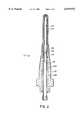
- FIG. 2is a sectional view of the mold core seen in FIG. 1,
- FIG. 3is an isometric view of part of the front portions of an inner part and an outer part showing the spiral grooves, and a front cap in position for assembly to form the mold core seen in FIG. 2,
- FIG. 4is cut-away isometric view of part of the integral front portions of the same mold core
- FIG. 5is a sectional view taken along line 55 in FIG. 4,
- FIG. 6is a sectional view taken along line 66 in FIG. 4,
- FIG. 7is a cut-away isometric view of a portion of the cooled mold core showing the turbulent flow of the cooling fluid in the spiral grooves therein,
- FIG. 8is a sectional view taken along line 88 in FIG. 7, and
- FIG. 9is a sectional view taken along line 99 in FIG. 7.
- FIGS. 1 and 2shows a portion of a multi-cavity injection molding system or apparatus used for molding beverage bottle preforms having a cooled mold core 10 according to a preferred embodiment of the invention.
- a number of heated nozzles 12are mounted in openings 14 in a mold 16 with the rear end 18 of each heated nozzle 12 abutting against the front face 20 of a steel melt distribution manifold 22.
- Each nozzle 12is heated by an integral electrical heating element 24 and has a thermocouple element 26 extending into its front end 28 to monitor and control the operating temperature.
- Each heated nozzle 12has a cylindrical locating flange 30 seated in a circular locating seat 32 in the opening 14. This provides an insulative air space 34 between the heated nozzle 12 and the surrounding mold 16, which is cooled by pumping cooling water through cooling conduits 36.
- the melt distribution manifold 22is also heated by an integral electrical heating element 38.
- the melt distribution manifold 22is mounted between a manifold plate 40 and a clamp plate 42 which are secured together by bolts 44.
- the melt distribution manifold 22is located by a central locating ring 46 and a number of resilient spacers 48 which provide an insulative air space 50 between it and the surrounding cooled mold 16.
- a melt passage 52extends from a central inlet 54 in an inlet portion 56 of the melt distribution manifold 22 and branches in the melt distribution manifold 22 to extend through a central melt bore 58 in each of the heated nozzles 12.
- the melt passage 52extends through a two-piece nozzle seal 60 aligned with a gate 62 extending through a cooled gate insert 64 to a cavity 66.
- This cavity 66 for making beverage bottle preformsextends between a cavity insert 68 and thread split inserts 70 on the outside and the cooled mold core 10 according to the invention on the inside.
- the gate insert 64 and the cavity insert 68are seated in an opening 72 in a cavity plate 74 through which cooling water lines (not shown) extend to the cooled gate insert 64.
- the cooled mold core 10has a hollow elongated inner part 78 which fits inside a hollow elongated outer part 80.
- the mold core 10extends rearwardly from the cavity 66 through an opening 82 in a core lock member 84 which is secured to a core backing plate 86 by screws 88.
- the core lock member 84extends through an opening 90 in a slide member 92 and a wear plate 94 which is secured to a stripper plate 96 by screws 98.
- Cooling fluid supply and return lines 100, 102extend in the core backing plate 86 and are connected respectively to a longitudinally extending central duct 104 in the inner part 78 and an outer cooling fluid duct 106 extending between a rear portion 108 of the inner part 78 and a rear portion 110 of the outer part 80.
- the mold 16can have different numbers and shapes of parts and plates depending upon the configuration required.
- the inner part 78 and the outer part 80have front portions 112, 114 with open front ends 116, 118.
- the front portion 112 of the inner part 78 with the central cooling fluid duct 104 extending therethroughhas an outer surface 120 with spiral grooves 122 extending therearound.
- the front portion 114 of the outer part 80has an outer surface 124 and an inner surface 126 which fits around the outer surface 120 of the front portion 112 of the inner part 78.
- the inner surface 126 of the front portion 114 of the outer part 80also has spiral grooves 128 extending therearound, but they spiral in the opposite direction to the spiral grooves 122 in the outer surface 120 of the front portion 112 of the inner part 78.
- the spiral grooves 128 in the outer surface 120 of the front portion 112 of the inner part 78 and the spiral grooves 128 in the inner surface 126 of the front portion 114 of the outer part 80stop a short distance from the open front ends 116, 118.
- a U-shaped circular channel 130is formed between the open front ends 116, 118 to receive a dome shaped front cap 132.
- the dome shaped front cap 132encloses the open front end 118 of the outer part 80 and provides a cooling fluid conveying space 134 to convey cooling fluid from the central duct 104 in the inner part 78 to the spiral grooves 122, 128 in the inner and outer parts 78, 80.
- the dome shaped front cap 132has an outer surface 136 and inner surface 138 with a number of curved ribs 140 which form curved grooves 142 between them.
- the outer surface 124 of the front portion 114 of the outer part 80 and the outer surface 136 of the front cap 132form an inner side 144 of the cavity 66.
- the curved grooves 142 in the inner surface 138 of the front cap 132are aligned with the spiral grooves 122 in the front portion 112 of the inner part 78 and the spiral grooves 128 in the front portion 114 of the outer part 80 to channel the cooling fluid from the central duct 104 in the inner part 78 into the spiral grooves 122, 128 in the inner and outer parts 78, 80.
- the front portion 112 of the inner part 78, the front and rear portions 114, 110 of the outer part 80, and the dome shaped front cap 132are assembled and integrally joined together by a suitable process such as brazing in a vacuum furnace or by hot isostatic pressing.
- the rear portion 108 of the inner part 78 called a bubbler tubeis press fitted into place with a sleeve portion 146 which fits inside the front portion 112 of the inner part 78.
- Integrally joining the front portion 112 of the inner part 78, the front and rear portions 114, 110 of the outer part 80 and the dome shaped front cap 132 togetherprovides the cooled mold core 10 with more strength which allows the spiral grooves 128 in the outer part 80 to be closer to the cavity 66.
- the central cooling fluid duct 104is precisely located in the center of the cooled mold core 10 and the spiral grooves 122, 128 extending in opposite directions ensures that the cooling fluid flow through them is very even. Both of these factors ensure that cooling to the melt in the cavity 66 is very uniform and not greater on one side than the other. As seen in FIGS. 7-9, the spiral grooves 122, 128 extending in opposite directions also forces the cooling fluid to flow both back and forth and in and out through the joined grooves 122, 128 resulting in very turbulent flow and more efficient cooling of the melt in the cavity 66.
- thermoelectric heating elements 24, 38heat the nozzles 12 and the melt distribution manifold 22 to a predetermined operating temperature.
- a suitable cooling fluidsuch as water is also circulated by pumps (not shown) through the cooling conduits 36 in the mold 16 and the lines leading to the cavity inserts 68.
- a cleaner cooling fluidsuch as glycol is pumped in a closed loop cooling system through the supply and return lines 100, 102 to circulate through the mold cores 10.
- Pressurized melt from a molding machine(not shown) is then introduced according to a predetermined injection cycle into the central inlet 54 of the melt passage 52 of the melt distribution manifold 22, from where it flows through the central melt bore 58 in each of the heated nozzles 12 and the two-piece nozzle seals 60 and through the gates 62 to fill the cavities 66.
- injection pressureis held momentarily to pack and then released.
- the mold 16is opened to eject the product. After ejection, the mold 16 is closed and the injection pressure is reapplied to refill the cavity 66. This cycle is repeated continuously with a cycle time that has been reduced as a result of improved cooling from the mold core 10.
Landscapes
- Engineering & Computer Science (AREA)
- Manufacturing & Machinery (AREA)
- Mechanical Engineering (AREA)
- Physics & Mathematics (AREA)
- Fluid Mechanics (AREA)
- Moulds For Moulding Plastics Or The Like (AREA)
- Thermotherapy And Cooling Therapy Devices (AREA)
Abstract
Description
Claims (3)
Applications Claiming Priority (2)
| Application Number | Priority Date | Filing Date | Title |
|---|---|---|---|
| CA2255798 | 1998-12-07 | ||
| CA002255798ACA2255798C (en) | 1998-12-07 | 1998-12-07 | Injection molding cooling core having spiral grooves |
Publications (1)
| Publication Number | Publication Date |
|---|---|
| US6079972Atrue US6079972A (en) | 2000-06-27 |
Family
ID=4163087
Family Applications (1)
| Application Number | Title | Priority Date | Filing Date |
|---|---|---|---|
| US09/218,637Expired - LifetimeUS6079972A (en) | 1998-12-07 | 1998-12-22 | Injection molding cooling core having spiral grooves |
Country Status (12)
| Country | Link |
|---|---|
| US (1) | US6079972A (en) |
| EP (1) | EP1137526B1 (en) |
| JP (1) | JP2002531297A (en) |
| KR (1) | KR100704045B1 (en) |
| CN (1) | CN1138623C (en) |
| AT (1) | ATE248055T1 (en) |
| AU (1) | AU1972300A (en) |
| BR (1) | BR9916953B1 (en) |
| CA (1) | CA2255798C (en) |
| DE (1) | DE69910823T2 (en) |
| PT (1) | PT1137526E (en) |
| WO (1) | WO2000034026A1 (en) |
Cited By (26)
| Publication number | Priority date | Publication date | Assignee | Title |
|---|---|---|---|---|
| US6276922B1 (en)* | 1999-08-24 | 2001-08-21 | Husky Injection Molding Systems Ltd. | Core fluid velocity inducer |
| WO2002022341A1 (en)* | 2000-09-12 | 2002-03-21 | Metallamics, Inc. | Injection molding cooling core and method of use |
| US6425752B1 (en)* | 1999-03-22 | 2002-07-30 | John M. Check | Bubbler tube with integral inlet pipe and bimetal core for injection molding tools and method of making the bubbler tube |
| US20030057598A1 (en)* | 2001-09-10 | 2003-03-27 | Brand Tiemo D. | Post mold cooling method and assembly for molded article neck finishes |
| WO2004018180A1 (en)* | 2002-08-09 | 2004-03-04 | Mht Mold & Hotrunner Technology Ag | Mould core of an injection moulding tool |
| WO2004067257A1 (en)* | 2003-01-25 | 2004-08-12 | Husky Injection Molding Systems Ltd. | Core cooling tube assembly |
| US20050097969A1 (en)* | 2002-06-17 | 2005-05-12 | Eltek S.P.A. | Device for measuring or checking a fluid, in particular for drink vendors, and method for manufacturing said device |
| US20050225008A1 (en)* | 2004-04-08 | 2005-10-13 | Deardurff L R | Method and apparatus for compression molding plastic articles |
| US20050263673A1 (en)* | 2004-05-25 | 2005-12-01 | Bachan Douglas J | Cooling injection mold |
| US20050265802A1 (en)* | 2004-05-27 | 2005-12-01 | Alltrista Zinc Products, L.P. | Environmentally protected reinforcement dowel pins and method of making |
| EP1724092A1 (en)* | 2005-05-20 | 2006-11-22 | gwk Gesellschaft Wärme Kältetechnik mbH | Mold to produce a hollow part in plastic |
| US20070092596A1 (en)* | 2005-10-20 | 2007-04-26 | Husky Injection Molding Systems Ltd. | Apparatus for cooling mold insert |
| US20070264383A1 (en)* | 2006-05-12 | 2007-11-15 | Husky Injection Molding Systems Ltd. | Mold-cooling device having vortex-inducing cooling-fluid chamber |
| US20070267783A1 (en)* | 2006-05-18 | 2007-11-22 | Husky Injection Molding Systems Ltd. | Mold-cooling device |
| US20080277820A1 (en)* | 2005-09-07 | 2008-11-13 | Zeno Zuffa | Moulds for Moulding Objects Made of Plastics and a Method for Producing a Mould Element |
| US20090068307A1 (en)* | 2007-09-07 | 2009-03-12 | Husky Injection Molding Systems Ltd. | Mold Insert and Mold Stack for Use with Molding Machine |
| US20090175976A1 (en)* | 2006-06-14 | 2009-07-09 | Fiorenzo Parrinello | Apparatus for compression moulding objects |
| EP2439043A1 (en)* | 2010-10-08 | 2012-04-11 | ifw Manfred Otte GmbH | Method for cooling an injection moulding tool |
| US8585392B2 (en) | 2011-05-24 | 2013-11-19 | F&S Tool, Inc. | Compression molding with successive stage cooling channels |
| CN103465400A (en)* | 2013-09-27 | 2013-12-25 | 乐清市恒通电气有限公司 | Forming mould for internal ring-shaped groove of industrial socket main shell |
| US20140044982A1 (en)* | 2011-04-28 | 2014-02-13 | Insstek, Inc. | Metal product having internal space formed therein and method of manufacturing thereof |
| EP2993022A3 (en)* | 2014-08-06 | 2016-04-20 | Porite Taiwan Co., Ltd. | Cooling structure of pressing mold |
| JP2017124595A (en)* | 2015-01-13 | 2017-07-20 | ユド バリュープロ ラブ カナダ インコーポレイテッド | Post-mold cooling method and apparatus with cyclone cooling effect |
| US10300633B2 (en) | 2012-03-21 | 2019-05-28 | Sacmi Cooperativa Meccanici Imola Societa' Cooperativa | Male mould element |
| US11198240B2 (en) | 2017-03-02 | 2021-12-14 | Nissei Asb Machine Co., Ltd. | Molding mold |
| CN114801077A (en)* | 2022-04-28 | 2022-07-29 | 佛山市利和精密机械有限公司 | Combined multi-group cooling belt exhaust mold core |
Families Citing this family (18)
| Publication number | Priority date | Publication date | Assignee | Title |
|---|---|---|---|---|
| CN100584573C (en)* | 1997-04-16 | 2010-01-27 | 赫斯基注射器成型系统有限公司 | Method and device for partial crystallization of amorphous plastic products |
| CA2255800C (en)* | 1998-12-07 | 2008-06-10 | Jobst Ulrich Gellert | Injection molding cooling core having a ribbed cap |
| FR2842753B1 (en)* | 2002-07-26 | 2005-03-11 | Financ D Etudes Et De Dev Ind | METHOD FOR PRODUCING A TOOL FOR FORMING A MATERIAL AND TOOL WHICH CAN BE CARRIED OUT BY THIS METHOD |
| CN102211370A (en)* | 2011-04-25 | 2011-10-12 | 广东亿龙电器股份有限公司 | Mould water-transporting structure and design method thereof |
| KR101351984B1 (en)* | 2012-01-13 | 2014-01-22 | 주식회사 유도 | Cold And Heat Medium Supply Apparatus For Mold |
| DE102013100277B4 (en)* | 2013-01-11 | 2018-06-21 | Peter Budde | Mold core, mold insert and mold for producing molded parts |
| TWI554380B (en)* | 2013-08-13 | 2016-10-21 | 沙克米機械合作伊莫拉公司 | A male mould element |
| US9738012B2 (en)* | 2013-09-20 | 2017-08-22 | Husky Injection Molding Systems Ltd. | Mold component |
| CN103448213A (en)* | 2013-09-25 | 2013-12-18 | 常熟市金马模具有限公司 | Rapid cooling die |
| KR101484585B1 (en)* | 2013-11-28 | 2015-01-20 | 김성식 | Apparatus for cooling inner-screw of melt extruder for conduit tube molding machine using scrapped plastic |
| CN107970764A (en)* | 2017-11-27 | 2018-05-01 | 常州五王电机有限公司 | A kind of SNCR denitrification spray gun |
| CN107999295A (en)* | 2017-11-27 | 2018-05-08 | 常州五王电机有限公司 | The SNCR denitrification spray gun that can quickly cool down |
| DE102018132332A1 (en)* | 2018-12-14 | 2020-06-18 | Mht Mold & Hotrunner Technology Ag | Core cooling system for a mold core of an injection mold |
| DE102018132339A1 (en)* | 2018-12-14 | 2020-06-18 | Mht Mold & Hotrunner Technology Ag | Core cooling system for a mold core of an injection mold |
| CN110239048B (en)* | 2019-05-31 | 2021-05-25 | 九江市利源塑业有限公司 | Injection mold with temperature control system |
| WO2022101770A1 (en)* | 2020-11-10 | 2022-05-19 | Sacmi Cooperativa Meccanici Imola Societa' Cooperativa | Male element of a mould |
| FR3124968A1 (en)* | 2021-07-07 | 2023-01-13 | Jackie André DERUYTER | Punch device and its cooling tube with flow inverter for PET preform mold |
| KR102469290B1 (en)* | 2022-08-17 | 2022-11-22 | 주식회사 에스제이프로텍 | Core cooling structure of injection mold |
Citations (5)
| Publication number | Priority date | Publication date | Assignee | Title |
|---|---|---|---|---|
| US4054630A (en)* | 1976-01-22 | 1977-10-18 | American Can Company | Hot pin parison injection molding technique |
| US4622001A (en)* | 1985-03-12 | 1986-11-11 | Electra Form, Inc. | Cavity cooling system |
| US4759708A (en)* | 1987-03-30 | 1988-07-26 | Bomatic, Inc. | Apparatus for extrusion blow molding of compartmented containers using dual cooled blow pins |
| US5094603A (en)* | 1990-12-17 | 1992-03-10 | Gellert Jobst U | Thermal valve gated injection molding apparatus with melt distribution plate |
| US5498150A (en)* | 1995-01-09 | 1996-03-12 | Check; John M. | High thermal capacity mold assembly |
Family Cites Families (4)
| Publication number | Priority date | Publication date | Assignee | Title |
|---|---|---|---|---|
| GB1502358A (en)* | 1976-08-17 | 1978-03-01 | Pioneer Plastic Containers Ltd | Injection mould part |
| DE3828383A1 (en)* | 1988-08-20 | 1990-03-15 | Agfa Gevaert Ag | Injection mould |
| JPH0759375B2 (en)* | 1991-07-03 | 1995-06-28 | 日精樹脂工業株式会社 | Mold for plastic lens |
| SG72784A1 (en)* | 1997-01-24 | 2000-05-23 | Mold Masters Ltd | Injection molding apparatus with cooled core |
- 1998
- 1998-12-07CACA002255798Apatent/CA2255798C/ennot_activeExpired - Fee Related
- 1998-12-22USUS09/218,637patent/US6079972A/ennot_activeExpired - Lifetime
- 1999
- 1999-12-07WOPCT/EP1999/009606patent/WO2000034026A1/enactiveIP Right Grant
- 1999-12-07BRBRPI9916953-3Apatent/BR9916953B1/ennot_activeIP Right Cessation
- 1999-12-07ATAT99963416Tpatent/ATE248055T1/ennot_activeIP Right Cessation
- 1999-12-07PTPT99963416Tpatent/PT1137526E/enunknown
- 1999-12-07CNCNB998142190Apatent/CN1138623C/ennot_activeExpired - Lifetime
- 1999-12-07EPEP99963416Apatent/EP1137526B1/ennot_activeExpired - Lifetime
- 1999-12-07AUAU19723/00Apatent/AU1972300A/ennot_activeAbandoned
- 1999-12-07DEDE69910823Tpatent/DE69910823T2/ennot_activeExpired - Lifetime
- 1999-12-07KRKR1020017007107Apatent/KR100704045B1/ennot_activeExpired - Fee Related
- 1999-12-07JPJP2000586502Apatent/JP2002531297A/enactivePending
Patent Citations (5)
| Publication number | Priority date | Publication date | Assignee | Title |
|---|---|---|---|---|
| US4054630A (en)* | 1976-01-22 | 1977-10-18 | American Can Company | Hot pin parison injection molding technique |
| US4622001A (en)* | 1985-03-12 | 1986-11-11 | Electra Form, Inc. | Cavity cooling system |
| US4759708A (en)* | 1987-03-30 | 1988-07-26 | Bomatic, Inc. | Apparatus for extrusion blow molding of compartmented containers using dual cooled blow pins |
| US5094603A (en)* | 1990-12-17 | 1992-03-10 | Gellert Jobst U | Thermal valve gated injection molding apparatus with melt distribution plate |
| US5498150A (en)* | 1995-01-09 | 1996-03-12 | Check; John M. | High thermal capacity mold assembly |
Non-Patent Citations (2)
| Title |
|---|
| Mold Masters Brochure entitled Introducing Master Stack Closure Molding Components no date.* |
| Mold-Masters Brochure entitled "Introducing Master-Stack Closure Molding Components" no date. |
Cited By (48)
| Publication number | Priority date | Publication date | Assignee | Title |
|---|---|---|---|---|
| US6425752B1 (en)* | 1999-03-22 | 2002-07-30 | John M. Check | Bubbler tube with integral inlet pipe and bimetal core for injection molding tools and method of making the bubbler tube |
| US6276922B1 (en)* | 1999-08-24 | 2001-08-21 | Husky Injection Molding Systems Ltd. | Core fluid velocity inducer |
| WO2002022341A1 (en)* | 2000-09-12 | 2002-03-21 | Metallamics, Inc. | Injection molding cooling core and method of use |
| US20030057598A1 (en)* | 2001-09-10 | 2003-03-27 | Brand Tiemo D. | Post mold cooling method and assembly for molded article neck finishes |
| US6802705B2 (en) | 2001-09-10 | 2004-10-12 | Husky Injection Molding Systems Ltd. | Post mold cooling assembly for molded article neck finishes |
| US20050097969A1 (en)* | 2002-06-17 | 2005-05-12 | Eltek S.P.A. | Device for measuring or checking a fluid, in particular for drink vendors, and method for manufacturing said device |
| US7117595B2 (en)* | 2002-06-17 | 2006-10-10 | Eltek S.P.A. | Method for manufacturing a conveying element of an axial type flow meter used for drink vendors |
| US20060121150A1 (en)* | 2002-08-09 | 2006-06-08 | Werner Plass | Mold core of an injection molding tool |
| WO2004018180A1 (en)* | 2002-08-09 | 2004-03-04 | Mht Mold & Hotrunner Technology Ag | Mould core of an injection moulding tool |
| WO2004067257A1 (en)* | 2003-01-25 | 2004-08-12 | Husky Injection Molding Systems Ltd. | Core cooling tube assembly |
| GB2397548B (en)* | 2003-01-25 | 2005-06-22 | Husky Injection Molding | Core cooling tube assembly |
| US7399174B2 (en) | 2004-04-08 | 2008-07-15 | Graham Packaging Pet Technologies Inc. | Method and apparatus for compression molding plastic articles |
| US20050225008A1 (en)* | 2004-04-08 | 2005-10-13 | Deardurff L R | Method and apparatus for compression molding plastic articles |
| US7351054B2 (en)* | 2004-05-25 | 2008-04-01 | Bachan Douglas J | Cooling injection mold |
| US20060131473A1 (en)* | 2004-05-25 | 2006-06-22 | Bachan Douglas J | Cooling injection mold |
| US20050263673A1 (en)* | 2004-05-25 | 2005-12-01 | Bachan Douglas J | Cooling injection mold |
| US7392970B2 (en)* | 2004-05-25 | 2008-07-01 | Douglas J Bachan | Cooling injection mold |
| US20060257231A1 (en)* | 2004-05-27 | 2006-11-16 | Alltrista Zinc Products, L.P. (an Indiana Limited partnership) | Environmentally protected reinforcement dowel pins and method of making |
| US20050265802A1 (en)* | 2004-05-27 | 2005-12-01 | Alltrista Zinc Products, L.P. | Environmentally protected reinforcement dowel pins and method of making |
| US7553554B2 (en) | 2004-05-27 | 2009-06-30 | Jarden Zinc Products, LLC | Environmentally protected reinforcement dowel pins and method of making |
| US20060263465A1 (en)* | 2005-05-20 | 2006-11-23 | Gwk Gesellschaft Warme Kaltetechnik Mbh | Cooled mold system for making a preform |
| US7607633B2 (en)* | 2005-05-20 | 2009-10-27 | Gwk Gesellschaft Warme Kaltetechnik Mbh | Cooled mold system for making a preform |
| EP1724092A1 (en)* | 2005-05-20 | 2006-11-22 | gwk Gesellschaft Wärme Kältetechnik mbH | Mold to produce a hollow part in plastic |
| US20080277820A1 (en)* | 2005-09-07 | 2008-11-13 | Zeno Zuffa | Moulds for Moulding Objects Made of Plastics and a Method for Producing a Mould Element |
| US8501067B2 (en) | 2005-09-07 | 2013-08-06 | Sacmi Cooperativa Meccanici Imola Societa' Cooperativa | Method for producing a mould element |
| US8038434B2 (en)* | 2005-09-07 | 2011-10-18 | Sacmi Cooperativa Meccanici Imola Societa' Cooperativa | Moulds for moulding objects made of plastics and a method for producing a mould element |
| US7361009B2 (en) | 2005-10-20 | 2008-04-22 | Husky Injection Molding Systems Ltd. | Mold cavity insert for use in an injection mold |
| US20070092596A1 (en)* | 2005-10-20 | 2007-04-26 | Husky Injection Molding Systems Ltd. | Apparatus for cooling mold insert |
| US20070264383A1 (en)* | 2006-05-12 | 2007-11-15 | Husky Injection Molding Systems Ltd. | Mold-cooling device having vortex-inducing cooling-fluid chamber |
| US20070267783A1 (en)* | 2006-05-18 | 2007-11-22 | Husky Injection Molding Systems Ltd. | Mold-cooling device |
| US8202076B2 (en) | 2006-06-14 | 2012-06-19 | Sacmi Cooperativa Meccanici Imola Societa' Cooperativa | Apparatus for compression moulding objects |
| US20090175976A1 (en)* | 2006-06-14 | 2009-07-09 | Fiorenzo Parrinello | Apparatus for compression moulding objects |
| US7645132B2 (en)* | 2007-09-07 | 2010-01-12 | Husky Injection Molding Systems Ltd. | Mold insert and mold stack for use with molding machine |
| US20090068307A1 (en)* | 2007-09-07 | 2009-03-12 | Husky Injection Molding Systems Ltd. | Mold Insert and Mold Stack for Use with Molding Machine |
| EP2439043A1 (en)* | 2010-10-08 | 2012-04-11 | ifw Manfred Otte GmbH | Method for cooling an injection moulding tool |
| US10479010B2 (en) | 2011-04-28 | 2019-11-19 | Insstek, Inc. | Metal product having internal space formed therein and method of manufacturing thereof |
| US20140044982A1 (en)* | 2011-04-28 | 2014-02-13 | Insstek, Inc. | Metal product having internal space formed therein and method of manufacturing thereof |
| US9636790B2 (en)* | 2011-04-28 | 2017-05-02 | Insstek, Inc. | Metal product having internal space formed therein and method of manufacturing thereof |
| US8585392B2 (en) | 2011-05-24 | 2013-11-19 | F&S Tool, Inc. | Compression molding with successive stage cooling channels |
| US20140035194A1 (en)* | 2011-05-24 | 2014-02-06 | F&S Tool, Inc. | Method of Molding and Mold with Succesive Stage Cooling Channels |
| US9475246B2 (en)* | 2011-05-24 | 2016-10-25 | F&S Tool, Inc. | Method of molding and mold with succesive stage cooling channels |
| US11123898B2 (en)* | 2012-03-21 | 2021-09-21 | Sacmi Cooperativa Meccanici Imola Societa' Cooperativa | Male mould element |
| US10300633B2 (en) | 2012-03-21 | 2019-05-28 | Sacmi Cooperativa Meccanici Imola Societa' Cooperativa | Male mould element |
| CN103465400A (en)* | 2013-09-27 | 2013-12-25 | 乐清市恒通电气有限公司 | Forming mould for internal ring-shaped groove of industrial socket main shell |
| EP2993022A3 (en)* | 2014-08-06 | 2016-04-20 | Porite Taiwan Co., Ltd. | Cooling structure of pressing mold |
| JP2017124595A (en)* | 2015-01-13 | 2017-07-20 | ユド バリュープロ ラブ カナダ インコーポレイテッド | Post-mold cooling method and apparatus with cyclone cooling effect |
| US11198240B2 (en) | 2017-03-02 | 2021-12-14 | Nissei Asb Machine Co., Ltd. | Molding mold |
| CN114801077A (en)* | 2022-04-28 | 2022-07-29 | 佛山市利和精密机械有限公司 | Combined multi-group cooling belt exhaust mold core |
Also Published As
| Publication number | Publication date |
|---|---|
| ATE248055T1 (en) | 2003-09-15 |
| CN1138623C (en) | 2004-02-18 |
| CA2255798C (en) | 2008-06-17 |
| EP1137526B1 (en) | 2003-08-27 |
| BR9916953A (en) | 2001-09-11 |
| CA2255798A1 (en) | 2000-06-07 |
| EP1137526A1 (en) | 2001-10-04 |
| AU1972300A (en) | 2000-06-26 |
| WO2000034026A1 (en) | 2000-06-15 |
| JP2002531297A (en) | 2002-09-24 |
| PT1137526E (en) | 2003-11-28 |
| BR9916953B1 (en) | 2009-01-13 |
| KR20010086087A (en) | 2001-09-07 |
| CN1329538A (en) | 2002-01-02 |
| KR100704045B1 (en) | 2007-04-05 |
| DE69910823T2 (en) | 2004-07-01 |
| DE69910823D1 (en) | 2003-10-02 |
Similar Documents
| Publication | Publication Date | Title |
|---|---|---|
| US6079972A (en) | Injection molding cooling core having spiral grooves | |
| US6176700B1 (en) | Injection molding cooled cavity insert | |
| US5443381A (en) | Injection molding one-piece insert having cooling chamber with radial rib portions | |
| US6017209A (en) | Injection molding cooled gate insert | |
| US6077067A (en) | Injection molding apparatus having a cooling core with a ribbed cap | |
| US5427519A (en) | Injection molding nozzle with helical cooling conduit | |
| CA2030287C (en) | Injection molding apparatus having separate heating element in the cavity forming insert | |
| EP0688656A1 (en) | Injection molding one-piece insert having cooling chamber with radial rib portions | |
| EP0855261B1 (en) | Injection molding apparatus with cooled core | |
| US5118280A (en) | Injection molding apparatus with integral cooling in a forward portion of the nozzle | |
| EP1140457B1 (en) | Injection molding apparatus having mold cores with reverse taper | |
| US5935621A (en) | Injection molding apparatus having a cooled core | |
| CA1272361A (en) | Ijection molding system having a thermal locating flange | |
| EP0422622A2 (en) | Injection molding insulated valve member | |
| USRE38265E1 (en) | Injection molding apparatus having a cooled core | |
| US4931009A (en) | Injection molding system having a thermal locating flange |
Legal Events
| Date | Code | Title | Description |
|---|---|---|---|
| STCF | Information on status: patent grant | Free format text:PATENTED CASE | |
| FEPP | Fee payment procedure | Free format text:PAYOR NUMBER ASSIGNED (ORIGINAL EVENT CODE: ASPN); ENTITY STATUS OF PATENT OWNER: LARGE ENTITY | |
| FEPP | Fee payment procedure | Free format text:PAYER NUMBER DE-ASSIGNED (ORIGINAL EVENT CODE: RMPN); ENTITY STATUS OF PATENT OWNER: LARGE ENTITY Free format text:PAYOR NUMBER ASSIGNED (ORIGINAL EVENT CODE: ASPN); ENTITY STATUS OF PATENT OWNER: LARGE ENTITY | |
| FPAY | Fee payment | Year of fee payment:4 | |
| REMI | Maintenance fee reminder mailed | ||
| AS | Assignment | Owner name:4437667 CANADA INC., CANADA Free format text:ASSIGNMENT OF ASSIGNORS INTEREST;ASSIGNORS:JOBST U. GELLERT;MOLD-MASTERS LIMITED;REEL/FRAME:019955/0181 Effective date:20071011 | |
| FPAY | Fee payment | Year of fee payment:8 | |
| AS | Assignment | Owner name:SOCIETE GENERALE, NEW YORK Free format text:SECURITY AGREEMENT;ASSIGNOR:4437667 CANADA INC.;REEL/FRAME:020174/0241 Effective date:20071011 Owner name:SOCIETE GENERALE,NEW YORK Free format text:SECURITY AGREEMENT;ASSIGNOR:4437667 CANADA INC.;REEL/FRAME:020174/0241 Effective date:20071011 | |
| FPAY | Fee payment | Year of fee payment:12 | |
| AS | Assignment | Owner name:MOLD-MASTERS (2007) LIMITED, CANADA Free format text:CHANGE OF NAME;ASSIGNOR:4437667 CANADA INC.;REEL/FRAME:029865/0890 Effective date:20071026 | |
| AS | Assignment | Owner name:MOLD-MASTERS LUXEMBOURG ACQUISITIONS S.A.R.L., A L Free format text:RELEASE BY SECURED PARTY;ASSIGNOR:SOCIETE GENERALE, A CORPORATION OF FRANCE;REEL/FRAME:030182/0506 Effective date:20130328 Owner name:4437667 CANADA INC. A/K/A MOLD-MASTERS (2007) LIMI Free format text:RELEASE BY SECURED PARTY;ASSIGNOR:SOCIETE GENERALE, A CORPORATION OF FRANCE;REEL/FRAME:030182/0506 Effective date:20130328 Owner name:MOLD-MASTERS LUXEMBOURG HOLDINGS S.A.R.L., A LIMIT Free format text:RELEASE BY SECURED PARTY;ASSIGNOR:SOCIETE GENERALE, A CORPORATION OF FRANCE;REEL/FRAME:030182/0506 Effective date:20130328 | |
| AS | Assignment | Owner name:BANK OF AMERICA, N.A., AS COLLATERAL AGENT, WISCON Free format text:SUPPLEMENTAL SECURITY AGREEMENT;ASSIGNOR:MOLD-MASTERS (2007) LIMITED;REEL/FRAME:034013/0738 Effective date:20141017 |