US6079800A - Active brake control with front-to-rear proportioning - Google Patents
Active brake control with front-to-rear proportioningDownload PDFInfo
- Publication number
- US6079800A US6079800AUS09/136,947US13694798AUS6079800AUS 6079800 AUS6079800 AUS 6079800AUS 13694798 AUS13694798 AUS 13694798AUS 6079800 AUS6079800 AUS 6079800A
- Authority
- US
- United States
- Prior art keywords
- speed
- driven
- vehicle
- wheel
- wheels
- Prior art date
- Legal status (The legal status is an assumption and is not a legal conclusion. Google has not performed a legal analysis and makes no representation as to the accuracy of the status listed.)
- Expired - Fee Related
Links
- 238000000034methodMethods0.000claimsdescription12
- 230000002708enhancing effectEffects0.000abstractdescription5
- 238000010586diagramMethods0.000description12
- 230000001965increasing effectEffects0.000description3
- 238000012986modificationMethods0.000description2
- 230000004048modificationEffects0.000description2
- 230000005540biological transmissionEffects0.000description1
- 238000004590computer programMethods0.000description1
- 230000003247decreasing effectEffects0.000description1
- 230000000977initiatory effectEffects0.000description1
- 238000012544monitoring processMethods0.000description1
Images


Classifications
- B—PERFORMING OPERATIONS; TRANSPORTING
- B60—VEHICLES IN GENERAL
- B60T—VEHICLE BRAKE CONTROL SYSTEMS OR PARTS THEREOF; BRAKE CONTROL SYSTEMS OR PARTS THEREOF, IN GENERAL; ARRANGEMENT OF BRAKING ELEMENTS ON VEHICLES IN GENERAL; PORTABLE DEVICES FOR PREVENTING UNWANTED MOVEMENT OF VEHICLES; VEHICLE MODIFICATIONS TO FACILITATE COOLING OF BRAKES
- B60T8/00—Arrangements for adjusting wheel-braking force to meet varying vehicular or ground-surface conditions, e.g. limiting or varying distribution of braking force
- B60T8/17—Using electrical or electronic regulation means to control braking
- B60T8/176—Brake regulation specially adapted to prevent excessive wheel slip during vehicle deceleration, e.g. ABS
- B60T8/1764—Regulation during travel on surface with different coefficients of friction, e.g. between left and right sides, mu-split or between front and rear
Definitions
- This inventionrelates to a motor vehicle active brake control (ABC), and more particularly to a control in which front-to-rear proportioning of brake torque is preserved during operation of the active brake control.
- ABSactive brake control
- the differential brakinginduces a desired yaw moment that may be determined either open-loop (that is, in response to driver inputs, such as steering wheel angle) or closed-loop (that is, in response to a deviation between desired and measured parameters, such as yaw rate or side slip velocity).
- the desired yaw momentis typically considered as a desired speed differential as between the left and right wheels, and the differential braking is controlled to achieve the desired speed differential.
- the controlis carried out by isolating the brakes of the driven axle (front or rear) from the master cylinder, and then individually adjusting the those brake pressures so that one of the driven wheels is allowed to free-wheel while the other driven wheel is braked as required to achieve the desired speed differential.
- ABCcan greatly enhance the handling of the vehicle, it also disturbs the normal front-to-rear proportioning of brake pressure carried out by the master cylinder. This phenomenon is especially noticeable in front-wheel-drive vehicles since the ABC reduces the overall braking effort at the front wheels, where the braking effort is usually concentrated. Typically, the driver reacts by increasing the brake pedal pressure, and the increased braking effort is provided by the un-driven wheel brakes. If the braking produces substantial wheel slip, an anti-lock brake control overrides the ABC control, at least to the extent required to stop the slipping.
- the present inventionis directed to an improved active brake control for carrying out a desired wheel speed differential for enhanced vehicle handling while maintaining the normal front-to-rear brake pressure proportioning ordinarily provided by the vehicle braking system.
- the target speeds for the wheels of the driven axle during active brake controlare determined as a combined function of the wheel speeds of the un-driven axle and the desired wheel speed differential.
- the target speeds for the driven wheelsare determined according to the measured speeds of the corresponding un-driven wheels, and one of the target speeds is reduced to reflect the desired wheel speed differential.
- the desired wheel speed differentialis designed to produce a clockwise yaw moment, the target speed for the driven wheel on the right-hand side of the vehicle is reduced; if the differential is designed to produce a counter-clockwise yaw moment, the target speed for the driven wheel on the left-hand side of the vehicle is reduced.
- the stability enhancing effect of the ABCis achieved without disturbing the ideal front-to-rear brake effort proportioning.
- FIG. 1is a diagram of a vehicle including an electronic controller and associated input and output devices constituting a control system for carrying out an active brake control.
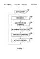
- FIG. 2is a main loop flow diagram representative of computer program instructions executed by the electronic controller of FIG. 1 in carrying out the control of this invention.
- FIG. 3is a flow diagram detailing a flow diagram block of FIG. 2 concerning the development a desired differential wheel speed for lateral stability enhancement.
- FIG. 4is a flow diagram detailing a flow diagram block of FIG. 2 concerning the development of target speeds for the driven wheels when ABC is active.
- FIG. 1depicts a mechanization of an active brake control (ABC) according to this invention on a front wheel drive vehicle 10.
- the vehicle 10includes a brake system including a brake pedal 64 mechanically coupled to a master cylinder 66 for producing hydraulic pressure in proportion to the force applied to pedal 64.
- the master cylinder 66which may include a pneumatic booster (not shown), proportions the hydraulic pressure among the front and rear brake supply lines 48 and 50 in a conventional manner.
- Front supply lines 48are coupled to the left front service brake 20 via ABC actuator 52, and to the right front service brake 22 via ABC actuator 54.
- Rear supply lines 50are coupled directly to the left and right rear wheel brakes 24 and 26.
- the micro-processor based controller 68controls the operation of the ABC actuators 52, 54 via lines 70, 72 to produce differential braking of the driven wheels 12, 14 for enhancing the lateral stability of the vehicle.
- the controller 68receives various inputs, including wheel speed signals on lines 36, 38, 40, 42 from respective wheel speed sensors 28, 30, 32, 34; an optional brake pedal travel signal on line 84 from pedal travel sensor 82; and a steering wheel angle signal on line 62 from angle sensor 61.
- the sensors 28, 30, 32, 34, 61 and 82may be implemented with conventional devices in a manner known to those skilled in the art.
- the controller 68modifies the normal braking of one or more of the driven wheels 12, 14 via the respective actuators 52, 54 in order to produce a corrective yaw moment.
- actuatorsare shown and described in detail in the U.S. Pat. No. 5,366,291, assigned to the assignee of the present invention.
- the actuators 52, 54operate during active brake control to isolate the respective brakes 20, 22 from the master cylinder 66, and then increase or decrease the respective brake pressures to produce a wheel speed differential corresponding to the needed corrective yaw moment.
- one of the driven wheelsis allowed to free-wheel, while the other driven wheel is braked as required to achieve the desired wheel speed differential.
- the desired wheel speed differentialis designed to produce a clockwise yaw moment
- the left-hand driven wheelis allowed to free-wheel
- the target speed for the right-hand driven wheelis set to the free-wheel speed (i.e., the measured speed of the left-hand wheel) less the desired speed differential
- the differentialis designed to produce a counter-clockwise yaw moment
- the right-hand driven wheelis allowed to free-wheel
- the target speed for the left-hand driven wheelis set to the free-wheel speed (i.e., the measured speed of the right-hand wheel) less the desired speed differential.
- this controlis carried out during driver braking, the front-to-rear brake effort proportioning normally provided by the master cylinder is disturbed, reducing the overall braking effort of the driven wheels.
- the active brake controlmaintains front-to-rear brake effort proportioning during driver braking by setting the target speeds of the driven wheels in relation to the measured speeds of the corresponding un-driven wheels, instead of the free-wheel speeds.
- the desired wheel speed differentialis designed to produce a clockwise yaw moment, the left-hand driven wheel is braked so that its speed matches the left-hand un-driven wheel, and the right-hand driven wheel is braked so that its speed matches the right-hand un-driven wheel, less the desired speed differential.
- the desired speed differentialis designed to produce a counter-clockwise yaw moment
- the right-hand driven wheelis braked so that its speed matches the right-hand un-driven wheel
- the left-hand driven wheelis braked so that its speed matches the left-hand un-driven wheel, less the desired speed differential.
- FIG. 2A main flow diagram for an active brake control incorporating the brake effort proportioning of this invention is set forth in FIG. 2.
- the vehicle 10has front-wheel drive, as discussed above, and the ABC determines the desired wheel speed differential by an open-loop technique as a function of the measured steering wheel angle ⁇ .
- the disclosed configurationis somewhat arbitrary, and that the brake proportioning control is equally applicable to other configurations, such as rear-wheel-drive arrangements, and closed-loop active brake controls.
- the reference numeral 100designates a series of initialization instructions executed at the initiation of vehicle operation for properly initializing certain variables and flags to initial values.
- the block 110is executed to read the various sensor inputs, including the wheel speed signals on lines 36-42, the steering angle signal on line 62, and the brake pedal travel signal (if available) on line 84.
- the block 120is executed to interpret the driver commands--that is, to form a desired wheel speed differential ⁇ V.
- the differential ⁇ Vis determined open-loop as a function of the measured vehicle speed V x and steering wheel angle ⁇ , as illustrated in the flow diagram of FIG. 3.
- the block 200is first executed to compute the desired yaw rate ⁇ des according to the expression:
- Lis wheel base of the vehicle
- K uis an understeer coefficient.
- the vehicle speed V xmay be derived either from the wheel speed information provided by sensors 28-34, or by another indication such as a transmission output shaft speed.
- block 210computes the rate of change of desired yaw rate ⁇ des ' for use in determining a derivative gain term.
- Blocks 220-230apply a dead-band and saturation function to the computed yaw rate and change of yaw rate to suitably limit the computed values, and blocks 240-250 then determine proportional and derivative yaw terms.
- the block 260determines a desired wheel speed differential ⁇ V(corresponding to a desired yaw moment) by summing the proportional and derivative terms.
- the block 130is then executed to determine target speeds for the driven wheels 12, 14 in accordance with this invention.
- This stepis illustrated in further detail in the flow diagram of FIG. 4, where the block 300 is first executed to determine if the vehicle is being braked by the driver. This may be determined by the brake pedal travel sensor 82, if available; preferably however, the controller 68 may detect deceleration due to braking by computing the deceleration of the non-driven wheels based on the wheel speed signals from sensors 32-34. If the computed deceleration exceeds a threshold, driver braking is detected. If there is no driver braking (i.e., block 300 answered in the negative), block 310 is executed to determine if the differential ⁇ V is positive or negative.
- a positive ⁇ Vcorresponds to a desired yaw moment in the clockwise direction
- a negative ⁇ Vcorresponds to a desired yaw moment in the counter-clockwise direction.
- the target speeds (RF in the block 320, and LF in block 330)may be determined in respect to the speed of the driven wheel on the same side of the vehicle, since the driven wheels are free-wheeling as well. That is, the target speed RF in block 320 could be computed as ( ⁇ RR - ⁇ V), and the target speed LF in block 330 could be computed as ( ⁇ LR - ⁇ V).
- block 340determines if the desired wheel speed differential ⁇ V is positive or negative, as described above. If ⁇ V is positive, block 350 sets the target speed LF for the left-front wheel 12 equal to the measured speed ⁇ LR of the left rear wheel 16, and the target speed RF for the right front wheel 14 equal to the measured speed ⁇ RR of the right rear wheel 18, less the differential ⁇ V. If ⁇ V is negative, block 360 sets the target speed LF equal to the measured speed ⁇ LR of the left rear wheel 16, less the differential ⁇ V, and the target speed RF equal to the measured speed ⁇ RR of the right rear wheel 18.
- the block 140is then executed to establish exit and enter conditions for active brake control.
- the entry conditionsmay involve comparing the vehicle velocity V x to a minimum velocity threshold V min , and determining if the desired differential wheel speed ⁇ V exceeds a minimum value V th .
- active brake controlmay be exited if, for example, the desired differential wheel speed ⁇ V is less than an exit threshold V ex for at least a predetermined period of time.
- entry and exit conditionsis given in the U.S. patent application Ser. No. 08/732,582, which is assigned to the assignee of the present invention.
- the main flow diagram block 150is then executed to suitably control the actuators 52 and 54 for making the front wheel speeds correspond to the respective target speeds determined at block 130. This simply involves monitoring the measured speeds of the controlled wheels, increasing the respective brake pressure when a monitored speed tends to exceed or exceeds its target speed, and decreasing the respective brake pressure when the monitored speed tends to fall below or falls below its target speed.
- the target speedmay be set to a very high speed so that no braking is applied.
- An example of such a controlis described in the aforementioned U.S. Pat. No. 5,015,040, incorporated herein by reference.
- control of this inventionprovides the stability enhancing effect of the ABC while maintaining an ideal front-to-rear brake effort proportioning during driver braking. While disclosed in reference to the illustrated embodiment, it is expected that various modifications will occur to those skilled in the art, and it should be understood that controls incorporating such modifications may fall within the scope of the present invention, which is defined by the appended claims.
Landscapes
- Engineering & Computer Science (AREA)
- Transportation (AREA)
- Mechanical Engineering (AREA)
- Regulating Braking Force (AREA)
Abstract
Description
Ω.sub.des =V.sub.x δ/(L+K.sub.u V.sub.x.sup.2)
Claims (7)
Priority Applications (1)
| Application Number | Priority Date | Filing Date | Title |
|---|---|---|---|
| US09/136,947US6079800A (en) | 1998-08-20 | 1998-08-20 | Active brake control with front-to-rear proportioning |
Applications Claiming Priority (1)
| Application Number | Priority Date | Filing Date | Title |
|---|---|---|---|
| US09/136,947US6079800A (en) | 1998-08-20 | 1998-08-20 | Active brake control with front-to-rear proportioning |
Publications (1)
| Publication Number | Publication Date |
|---|---|
| US6079800Atrue US6079800A (en) | 2000-06-27 |
Family
ID=22475150
Family Applications (1)
| Application Number | Title | Priority Date | Filing Date |
|---|---|---|---|
| US09/136,947Expired - Fee RelatedUS6079800A (en) | 1998-08-20 | 1998-08-20 | Active brake control with front-to-rear proportioning |
Country Status (1)
| Country | Link |
|---|---|
| US (1) | US6079800A (en) |
Cited By (9)
| Publication number | Priority date | Publication date | Assignee | Title |
|---|---|---|---|---|
| US6427130B1 (en)* | 1997-07-02 | 2002-07-30 | Robert Bosch Gmbh | Method and device for regulating a quantity of motion representing the movement of a vehicle |
| US6443540B2 (en)* | 2000-02-14 | 2002-09-03 | Toyota Jidosha Kabushiki Kaisha | Vehicular brake control apparatus and vehicular brake control method |
| US6443541B1 (en) | 1999-12-16 | 2002-09-03 | Toyota Jidosha Kabushiki Kaisha | Braking control apparatus and method for vehicles |
| US6560524B2 (en) | 2001-09-26 | 2003-05-06 | General Motors Corporation | Integration of rear wheel steering with vehicle stability enhancement system |
| US20050288842A1 (en)* | 2004-06-29 | 2005-12-29 | Ford Global Technologies, Llc | Method and apparatus for determining a reference vehicle velocity and a rear wheel speed in a vehicle having three speed sensors |
| US20080021617A1 (en)* | 2004-04-16 | 2008-01-24 | Daimlerchrysler Ag | Method for Actuating a Vehicle Occupant Protection Device in a Vehicle and a Vehicle Occupant Protection System |
| US20080262689A1 (en)* | 2007-04-17 | 2008-10-23 | Jcb Landpower Limited | Method of Operating A Vehicle |
| US20180229705A1 (en)* | 2015-07-27 | 2018-08-16 | Volvo Truck Corporation | Abs strategy for hybrid brake actuators |
| US20220250678A1 (en)* | 2021-02-08 | 2022-08-11 | Continental Automotive Gmbh | Regulating device and method for regulating the steering angle of a vehicle |
Citations (30)
| Publication number | Priority date | Publication date | Assignee | Title |
|---|---|---|---|---|
| US4834205A (en)* | 1987-02-03 | 1989-05-30 | Kabushiki Kaisha Toyota Chuo Kenkyusho | Apparatus for controlling steering of wheels of a vehicle |
| US5063514A (en)* | 1990-06-19 | 1991-11-05 | General Motors Corporation | Abs yaw control |
| DE4123235C1 (en)* | 1991-07-13 | 1992-11-26 | Daimler Benz Ag | |
| US5172961A (en)* | 1990-07-05 | 1992-12-22 | Nissan Motor Co. Ltd. | Vehicle brake system including cornering characteristic control |
| DE4121954A1 (en)* | 1991-07-03 | 1993-01-07 | Bosch Gmbh Robert | METHOD FOR OBTAINING THE YEAR SPEED AND / OR THE LATERAL SPEED |
| DE4200061A1 (en)* | 1992-01-03 | 1993-07-08 | Bosch Gmbh Robert | METHOD FOR DETERMINING THE VEHICLE CROSS SPEED AND / OR THE SWIMMING ANGLE |
| US5229944A (en)* | 1990-03-22 | 1993-07-20 | Yoshiki Yasuno | Braking force control apparatus |
| GB2263340A (en)* | 1992-01-16 | 1993-07-21 | Steyr Daimler Puch Ag | Method for determining the dynamic safety margin of motor vehicles |
| EP0555860A1 (en)* | 1992-02-14 | 1993-08-18 | Honda Giken Kogyo Kabushiki Kaisha | Steering stability control system for vehicle |
| US5275475A (en)* | 1990-08-23 | 1994-01-04 | Robert Bosch Gmbh | Method for controlling vehicle dynamics |
| DE4223385A1 (en)* | 1992-07-16 | 1994-01-20 | Bosch Gmbh Robert | Detecting reverse motion of motor vehicle for brake control system - measuring yaw rate, vehicle speed, wheel state and steering angle and using given equations to derive forward or reverse motion signals |
| GB2269571A (en)* | 1992-08-13 | 1994-02-16 | Daimler Benz Ag | Process for determining quantities characterising vehicle travel behaviour. |
| DE4229504A1 (en)* | 1992-09-04 | 1994-03-10 | Bosch Gmbh Robert | Vehicle road-curve stability regulation procedure - involves regulation of actual yaw velocity by comparison with required value as calculated from detected parameters |
| US5332300A (en)* | 1987-09-22 | 1994-07-26 | Robert Bosch Gmbh | Process for controlling the stability of vehicles |
| GB2275312A (en)* | 1993-02-19 | 1994-08-24 | Bosch Gmbh Robert | Vehicle movement dynamics control system |
| GB2275551A (en)* | 1991-10-21 | 1994-08-31 | Intel Corp | Cross coupling mechanisms for microprocessor instructions using pipelining systems. |
| DE4311077A1 (en)* | 1993-04-03 | 1994-10-06 | Bosch Gmbh Robert | Anti-lock control system |
| DE4314827A1 (en)* | 1993-05-05 | 1994-11-10 | Porsche Ag | Method for determining the yaw velocity of a vehicle |
| US5366281A (en)* | 1994-02-14 | 1994-11-22 | General Motors Corporation | Method of initializing a brake actuator |
| US5444621A (en)* | 1991-06-10 | 1995-08-22 | Nippondenso Co., Ltd. | Suspension control system for controlling suspension of automotive vehicle based on wheel speed data |
| US5480219A (en)* | 1992-12-23 | 1996-01-02 | Robert Bosch Gmbh | Control of vehicle side slip using yaw rate |
| US5667286A (en)* | 1996-05-29 | 1997-09-16 | General Motors Corporation | Brake control system |
| US5707120A (en)* | 1995-10-18 | 1998-01-13 | Toyota Jidosha Kabushiki Kaisha | Stability control device of vehicle improved against hunting |
| US5709439A (en)* | 1995-10-25 | 1998-01-20 | Toyota Jidosha Kabushiki Kaisha | Stability control device of vehicle prepared for manual brake uprise subsequent to end of stability control |
| US5720533A (en)* | 1996-10-15 | 1998-02-24 | General Motors Corporation | Brake control system |
| US5727853A (en)* | 1995-10-25 | 1998-03-17 | Toyota Jidosha Kabushiki Kaisha | Stability control device of vehicle improved against hunting |
| US5746486A (en)* | 1996-10-16 | 1998-05-05 | General Motors Corporation | Brake control system |
| US5782543A (en)* | 1995-10-11 | 1998-07-21 | Toyota Jidosha Kabushiki Kaisha | Stability control device of vehicle compatible with foot braking |
| US5839799A (en)* | 1995-10-06 | 1998-11-24 | Toyota Jidosha Kabushiki Kaisha | Behavior control device of vehicle based upon monitoring movement of rear wheels |
| US5931887A (en)* | 1998-09-24 | 1999-08-03 | General Motors Corporation | Brake control method based on a linear transfer function reference model |
- 1998
- 1998-08-20USUS09/136,947patent/US6079800A/ennot_activeExpired - Fee Related
Patent Citations (33)
| Publication number | Priority date | Publication date | Assignee | Title |
|---|---|---|---|---|
| US4834205A (en)* | 1987-02-03 | 1989-05-30 | Kabushiki Kaisha Toyota Chuo Kenkyusho | Apparatus for controlling steering of wheels of a vehicle |
| US5332300A (en)* | 1987-09-22 | 1994-07-26 | Robert Bosch Gmbh | Process for controlling the stability of vehicles |
| US5229944A (en)* | 1990-03-22 | 1993-07-20 | Yoshiki Yasuno | Braking force control apparatus |
| US5063514A (en)* | 1990-06-19 | 1991-11-05 | General Motors Corporation | Abs yaw control |
| US5172961A (en)* | 1990-07-05 | 1992-12-22 | Nissan Motor Co. Ltd. | Vehicle brake system including cornering characteristic control |
| US5275475A (en)* | 1990-08-23 | 1994-01-04 | Robert Bosch Gmbh | Method for controlling vehicle dynamics |
| US5444621A (en)* | 1991-06-10 | 1995-08-22 | Nippondenso Co., Ltd. | Suspension control system for controlling suspension of automotive vehicle based on wheel speed data |
| US5311431A (en)* | 1991-07-03 | 1994-05-10 | Robert Bosch Gmbh | Method of obtaining the yawing velocity and/or transverse velocity of a vehicle |
| DE4121954A1 (en)* | 1991-07-03 | 1993-01-07 | Bosch Gmbh Robert | METHOD FOR OBTAINING THE YEAR SPEED AND / OR THE LATERAL SPEED |
| DE4123235C1 (en)* | 1991-07-13 | 1992-11-26 | Daimler Benz Ag | |
| US5341297A (en)* | 1991-07-13 | 1994-08-23 | Mercedes-Benz Ag | Apparatus and method for preventing instabilities in vehicle handling |
| GB2275551A (en)* | 1991-10-21 | 1994-08-31 | Intel Corp | Cross coupling mechanisms for microprocessor instructions using pipelining systems. |
| DE4200061A1 (en)* | 1992-01-03 | 1993-07-08 | Bosch Gmbh Robert | METHOD FOR DETERMINING THE VEHICLE CROSS SPEED AND / OR THE SWIMMING ANGLE |
| GB2263340A (en)* | 1992-01-16 | 1993-07-21 | Steyr Daimler Puch Ag | Method for determining the dynamic safety margin of motor vehicles |
| EP0555860A1 (en)* | 1992-02-14 | 1993-08-18 | Honda Giken Kogyo Kabushiki Kaisha | Steering stability control system for vehicle |
| DE4223385A1 (en)* | 1992-07-16 | 1994-01-20 | Bosch Gmbh Robert | Detecting reverse motion of motor vehicle for brake control system - measuring yaw rate, vehicle speed, wheel state and steering angle and using given equations to derive forward or reverse motion signals |
| GB2269571A (en)* | 1992-08-13 | 1994-02-16 | Daimler Benz Ag | Process for determining quantities characterising vehicle travel behaviour. |
| DE4229504A1 (en)* | 1992-09-04 | 1994-03-10 | Bosch Gmbh Robert | Vehicle road-curve stability regulation procedure - involves regulation of actual yaw velocity by comparison with required value as calculated from detected parameters |
| US5402342A (en)* | 1992-09-04 | 1995-03-28 | Robert Bosch Gmbh | Method for controlling motor vehicle stability |
| US5480219A (en)* | 1992-12-23 | 1996-01-02 | Robert Bosch Gmbh | Control of vehicle side slip using yaw rate |
| GB2275312A (en)* | 1993-02-19 | 1994-08-24 | Bosch Gmbh Robert | Vehicle movement dynamics control system |
| DE4311077A1 (en)* | 1993-04-03 | 1994-10-06 | Bosch Gmbh Robert | Anti-lock control system |
| DE4314827A1 (en)* | 1993-05-05 | 1994-11-10 | Porsche Ag | Method for determining the yaw velocity of a vehicle |
| US5366281A (en)* | 1994-02-14 | 1994-11-22 | General Motors Corporation | Method of initializing a brake actuator |
| US5839799A (en)* | 1995-10-06 | 1998-11-24 | Toyota Jidosha Kabushiki Kaisha | Behavior control device of vehicle based upon monitoring movement of rear wheels |
| US5782543A (en)* | 1995-10-11 | 1998-07-21 | Toyota Jidosha Kabushiki Kaisha | Stability control device of vehicle compatible with foot braking |
| US5707120A (en)* | 1995-10-18 | 1998-01-13 | Toyota Jidosha Kabushiki Kaisha | Stability control device of vehicle improved against hunting |
| US5709439A (en)* | 1995-10-25 | 1998-01-20 | Toyota Jidosha Kabushiki Kaisha | Stability control device of vehicle prepared for manual brake uprise subsequent to end of stability control |
| US5727853A (en)* | 1995-10-25 | 1998-03-17 | Toyota Jidosha Kabushiki Kaisha | Stability control device of vehicle improved against hunting |
| US5667286A (en)* | 1996-05-29 | 1997-09-16 | General Motors Corporation | Brake control system |
| US5720533A (en)* | 1996-10-15 | 1998-02-24 | General Motors Corporation | Brake control system |
| US5746486A (en)* | 1996-10-16 | 1998-05-05 | General Motors Corporation | Brake control system |
| US5931887A (en)* | 1998-09-24 | 1999-08-03 | General Motors Corporation | Brake control method based on a linear transfer function reference model |
Non-Patent Citations (22)
| Title |
|---|
| Active Stability Control; Junichi Kubokawa, Aisin Seiki Co., Ltd., Electronics & Brake Division; Abstract; Sep. 1995.* |
| Consideration of Lateral and Longitudinal Vehicle Stability by Function Enhanced Brake and Stability Control System; Heinz Leffler; SAE #940832; Feb. 28-Mar. 3, 1994. |
| Consideration of Lateral and Longitudinal Vehicle Stability by Function Enhanced Brake and Stability Control System; Heinz Leffler; SAE 940832; Feb. 28 Mar. 3, 1994.* |
| Control of Vehicle Dynamics: Automotive Engineering; pp. 87 93; May 1995.* |
| Control of Vehicle Dynamics: Automotive Engineering; pp. 87-93; May 1995. |
| Controlling Vehicle Stability; Christopher A. Sawyer, Automotive Industries, Jan. 1995.* |
| Handling Control Systems For Your Car: Popular Electronics; Feb. 1995.* |
| Improvement of Vehicle Maneuverability by Direct Yaw Moment Control; Y. Shibahata, K. Shimada and T. Tomari; Society of Automotive Engineers of Japan, Inc.; pp. 464 481.* |
| Improvement of Vehicle Maneuverability by Direct Yaw Moment Control; Y. Shibahata, K. Shimada and T. Tomari; Society of Automotive Engineers of Japan, Inc.; pp. 464-481. |
| Let Magic Fingers Do the Driving: Wards Auto World; May 1995.* |
| May the Cornering Force be with You; Popular Mechanics; Dec. 1995, pp. 74 77.* |
| May the Cornering Force be with You; Popular Mechanics; Dec. 1995, pp. 74-77. |
| Mercedes/Bosch Esp; Automotive Industries, Apr. 1995.* |
| Spin Control for Cars; Steven Ashley; Mechanical Engineering; pp. 66 68; Jun. 1995.* |
| Spin Control for Cars; Steven Ashley; Mechanical Engineering; pp. 66-68; Jun. 1995. |
| Stable as She Goes: Don Sherman, Automotive Industries, May 1995.* |
| Technoid: Intelligent Brakes Are on the Way; Car and Driver, Aug. 1994.* |
| The Spin Doctors: Don Sherman, 12PS95.* |
| Toyota Vehicle Stability Control System; Automotive Engineering, Aug. 1995.* |
| VDC, The Vehicle Dynamics Control System of Bosch: A. VanZanten, R. Erhardt and G. Pfaff; Robert Bosch GmbH; No. 950759, pp. 9 26.* |
| VDC, The Vehicle Dynamics Control System of Bosch: A. VanZanten, R. Erhardt and G. Pfaff; Robert Bosch GmbH; No. 950759, pp. 9-26. |
| Vehicle Dynamics Offers New Level of Safety: Machine Design, Sep. 1994.* |
Cited By (13)
| Publication number | Priority date | Publication date | Assignee | Title |
|---|---|---|---|---|
| US6427130B1 (en)* | 1997-07-02 | 2002-07-30 | Robert Bosch Gmbh | Method and device for regulating a quantity of motion representing the movement of a vehicle |
| US6443541B1 (en) | 1999-12-16 | 2002-09-03 | Toyota Jidosha Kabushiki Kaisha | Braking control apparatus and method for vehicles |
| US6443540B2 (en)* | 2000-02-14 | 2002-09-03 | Toyota Jidosha Kabushiki Kaisha | Vehicular brake control apparatus and vehicular brake control method |
| US6560524B2 (en) | 2001-09-26 | 2003-05-06 | General Motors Corporation | Integration of rear wheel steering with vehicle stability enhancement system |
| US20080021617A1 (en)* | 2004-04-16 | 2008-01-24 | Daimlerchrysler Ag | Method for Actuating a Vehicle Occupant Protection Device in a Vehicle and a Vehicle Occupant Protection System |
| US8775048B2 (en) | 2004-06-29 | 2014-07-08 | Ford Global Techologies | Method and apparatus for determining a reference vehicle velocity and a rear wheel speed in a vehicle having three speed sensors |
| US20050288842A1 (en)* | 2004-06-29 | 2005-12-29 | Ford Global Technologies, Llc | Method and apparatus for determining a reference vehicle velocity and a rear wheel speed in a vehicle having three speed sensors |
| US8364365B2 (en)* | 2004-06-29 | 2013-01-29 | Ford Global Technologies | Method and apparatus for determining a reference vehicle velocity and a rear wheel speed in a vehicle having three speed sensors |
| US20080262689A1 (en)* | 2007-04-17 | 2008-10-23 | Jcb Landpower Limited | Method of Operating A Vehicle |
| US20180229705A1 (en)* | 2015-07-27 | 2018-08-16 | Volvo Truck Corporation | Abs strategy for hybrid brake actuators |
| US10766472B2 (en)* | 2015-07-27 | 2020-09-08 | Volvo Truck Corporation | ABS strategy for hybrid brake actuators |
| US20220250678A1 (en)* | 2021-02-08 | 2022-08-11 | Continental Automotive Gmbh | Regulating device and method for regulating the steering angle of a vehicle |
| US11981379B2 (en)* | 2021-02-08 | 2024-05-14 | Continental Automotive Gmbh | Regulating device and method for regulating the steering angle of a vehicle |
Similar Documents
| Publication | Publication Date | Title |
|---|---|---|
| US6205391B1 (en) | Vehicle yaw control based on yaw rate estimate | |
| US6179394B1 (en) | Active brake balance control method | |
| US5624164A (en) | Braking force distribution control system | |
| US7125086B2 (en) | Vehicle dynamics control system | |
| JP3215414B2 (en) | Wheel slip control device | |
| US20050004738A1 (en) | Method for modifying a driving stability control of a vehicle | |
| US6112147A (en) | Vehicle yaw rate control with bank angle compensation | |
| US5829847A (en) | Vehicle motion control system | |
| US6003959A (en) | Vehicle dynamics control system | |
| US5842755A (en) | Braking force control system in vehicle | |
| US5058018A (en) | Anti-skid control system for a road surface having a split coefficient of friction | |
| JP3812017B2 (en) | Vehicle motion control device | |
| US6079800A (en) | Active brake control with front-to-rear proportioning | |
| US6238018B1 (en) | Process for controlling braking-force distribution in vehicle | |
| US6223135B1 (en) | Method and device for determining a variable describing the speed of a vehicle | |
| US5707119A (en) | Stability control device of vehicle adaptive to failure of wheel speed sensor | |
| US6974195B2 (en) | Method for increasing the maneuverability or driving stability of a vehicle during cornering | |
| JP2927899B2 (en) | Anti-spin brake control device | |
| JP3248272B2 (en) | Braking force distribution control device | |
| JP3123099B2 (en) | Braking force control device | |
| JP2572856B2 (en) | Vehicle turning behavior control device | |
| JP3205684B2 (en) | Vehicle braking force distribution control method | |
| US6496769B1 (en) | Four wheel drive anti-lock brake control having torque transfer alleviation | |
| JP3554569B2 (en) | Braking force distribution control device | |
| JP2002137721A (en) | Vehicle motion control device |
Legal Events
| Date | Code | Title | Description |
|---|---|---|---|
| AS | Assignment | Owner name:GENERAL MOTORS CORPORATION, MICHIGAN Free format text:ASSIGNMENT OF ASSIGNORS INTEREST;ASSIGNORS:LIN, WILLIAM CHIN-WOEI;GHONEIM, YOUSSEF AHMED;SIDLOSKY, DAVID MICHAEL;AND OTHERS;REEL/FRAME:009399/0384;SIGNING DATES FROM 19980602 TO 19980608 | |
| FPAY | Fee payment | Year of fee payment:4 | |
| FPAY | Fee payment | Year of fee payment:8 | |
| AS | Assignment | Owner name:GM GLOBAL TECHNOLOGY OPERATIONS, INC., MICHIGAN Free format text:ASSIGNMENT OF ASSIGNORS INTEREST;ASSIGNOR:GENERAL MOTORS CORPORATION;REEL/FRAME:022117/0047 Effective date:20050119 Owner name:GM GLOBAL TECHNOLOGY OPERATIONS, INC.,MICHIGAN Free format text:ASSIGNMENT OF ASSIGNORS INTEREST;ASSIGNOR:GENERAL MOTORS CORPORATION;REEL/FRAME:022117/0047 Effective date:20050119 | |
| AS | Assignment | Owner name:UNITED STATES DEPARTMENT OF THE TREASURY, DISTRICT Free format text:SECURITY AGREEMENT;ASSIGNOR:GM GLOBAL TECHNOLOGY OPERATIONS, INC.;REEL/FRAME:022201/0501 Effective date:20081231 | |
| AS | Assignment | Owner name:CITICORP USA, INC. AS AGENT FOR BANK PRIORITY SECU Free format text:SECURITY AGREEMENT;ASSIGNOR:GM GLOBAL TECHNOLOGY OPERATIONS, INC.;REEL/FRAME:022556/0013 Effective date:20090409 Owner name:CITICORP USA, INC. AS AGENT FOR HEDGE PRIORITY SEC Free format text:SECURITY AGREEMENT;ASSIGNOR:GM GLOBAL TECHNOLOGY OPERATIONS, INC.;REEL/FRAME:022556/0013 Effective date:20090409 | |
| AS | Assignment | Owner name:GM GLOBAL TECHNOLOGY OPERATIONS, INC., MICHIGAN Free format text:RELEASE BY SECURED PARTY;ASSIGNOR:UNITED STATES DEPARTMENT OF THE TREASURY;REEL/FRAME:023238/0015 Effective date:20090709 | |
| XAS | Not any more in us assignment database | Free format text:RELEASE BY SECURED PARTY;ASSIGNOR:UNITED STATES DEPARTMENT OF THE TREASURY;REEL/FRAME:023124/0383 | |
| AS | Assignment | Owner name:GM GLOBAL TECHNOLOGY OPERATIONS, INC., MICHIGAN Free format text:RELEASE BY SECURED PARTY;ASSIGNORS:CITICORP USA, INC. AS AGENT FOR BANK PRIORITY SECURED PARTIES;CITICORP USA, INC. AS AGENT FOR HEDGE PRIORITY SECURED PARTIES;REEL/FRAME:023127/0326 Effective date:20090814 | |
| AS | Assignment | Owner name:UNITED STATES DEPARTMENT OF THE TREASURY, DISTRICT Free format text:SECURITY AGREEMENT;ASSIGNOR:GM GLOBAL TECHNOLOGY OPERATIONS, INC.;REEL/FRAME:023155/0922 Effective date:20090710 | |
| AS | Assignment | Owner name:UAW RETIREE MEDICAL BENEFITS TRUST, MICHIGAN Free format text:SECURITY AGREEMENT;ASSIGNOR:GM GLOBAL TECHNOLOGY OPERATIONS, INC.;REEL/FRAME:023161/0864 Effective date:20090710 | |
| AS | Assignment | Owner name:GM GLOBAL TECHNOLOGY OPERATIONS, INC., MICHIGAN Free format text:RELEASE BY SECURED PARTY;ASSIGNOR:UAW RETIREE MEDICAL BENEFITS TRUST;REEL/FRAME:025311/0680 Effective date:20101026 Owner name:GM GLOBAL TECHNOLOGY OPERATIONS, INC., MICHIGAN Free format text:RELEASE BY SECURED PARTY;ASSIGNOR:UNITED STATES DEPARTMENT OF THE TREASURY;REEL/FRAME:025245/0273 Effective date:20100420 | |
| AS | Assignment | Owner name:WILMINGTON TRUST COMPANY, DELAWARE Free format text:SECURITY AGREEMENT;ASSIGNOR:GM GLOBAL TECHNOLOGY OPERATIONS, INC.;REEL/FRAME:025327/0222 Effective date:20101027 | |
| AS | Assignment | Owner name:GM GLOBAL TECHNOLOGY OPERATIONS LLC, MICHIGAN Free format text:CHANGE OF NAME;ASSIGNOR:GM GLOBAL TECHNOLOGY OPERATIONS, INC.;REEL/FRAME:025780/0795 Effective date:20101202 | |
| REMI | Maintenance fee reminder mailed | ||
| LAPS | Lapse for failure to pay maintenance fees | ||
| STCH | Information on status: patent discontinuation | Free format text:PATENT EXPIRED DUE TO NONPAYMENT OF MAINTENANCE FEES UNDER 37 CFR 1.362 | |
| FP | Lapsed due to failure to pay maintenance fee | Effective date:20120627 |