US6079755A - Electromagnetic lock device - Google Patents
Electromagnetic lock deviceDownload PDFInfo
- Publication number
- US6079755A US6079755AUS09/327,000US32700099AUS6079755AUS 6079755 AUS6079755 AUS 6079755AUS 32700099 AUS32700099 AUS 32700099AUS 6079755 AUS6079755 AUS 6079755A
- Authority
- US
- United States
- Prior art keywords
- latch
- housing
- follower
- spindle
- lock device
- Prior art date
- Legal status (The legal status is an assumption and is not a legal conclusion. Google has not performed a legal analysis and makes no representation as to the accuracy of the status listed.)
- Expired - Fee Related
Links
- 230000008878couplingEffects0.000claimsdescription7
- 238000010168coupling processMethods0.000claimsdescription7
- 238000005859coupling reactionMethods0.000claimsdescription7
- 238000010276constructionMethods0.000description1
Images


Classifications
- E—FIXED CONSTRUCTIONS
- E05—LOCKS; KEYS; WINDOW OR DOOR FITTINGS; SAFES
- E05B—LOCKS; ACCESSORIES THEREFOR; HANDCUFFS
- E05B47/00—Operating or controlling locks or other fastening devices by electric or magnetic means
- E05B47/02—Movement of the bolt by electromagnetic means; Adaptation of locks, latches, or parts thereof, for movement of the bolt by electromagnetic means
- E05B47/026—Movement of the bolt by electromagnetic means; Adaptation of locks, latches, or parts thereof, for movement of the bolt by electromagnetic means the bolt moving rectilinearly
- E—FIXED CONSTRUCTIONS
- E05—LOCKS; KEYS; WINDOW OR DOOR FITTINGS; SAFES
- E05B—LOCKS; ACCESSORIES THEREFOR; HANDCUFFS
- E05B47/00—Operating or controlling locks or other fastening devices by electric or magnetic means
- E05B47/0001—Operating or controlling locks or other fastening devices by electric or magnetic means with electric actuators; Constructional features thereof
- E05B47/0002—Operating or controlling locks or other fastening devices by electric or magnetic means with electric actuators; Constructional features thereof with electromagnets
- E—FIXED CONSTRUCTIONS
- E05—LOCKS; KEYS; WINDOW OR DOOR FITTINGS; SAFES
- E05B—LOCKS; ACCESSORIES THEREFOR; HANDCUFFS
- E05B15/00—Other details of locks; Parts for engagement by bolts of fastening devices
- E05B15/10—Bolts of locks or night latches
- E05B15/101—Spring-retracted bolts
- E—FIXED CONSTRUCTIONS
- E05—LOCKS; KEYS; WINDOW OR DOOR FITTINGS; SAFES
- E05B—LOCKS; ACCESSORIES THEREFOR; HANDCUFFS
- E05B47/00—Operating or controlling locks or other fastening devices by electric or magnetic means
- E05B2047/0072—Operation
- E05B2047/0073—Current to unlock only
- E—FIXED CONSTRUCTIONS
- E05—LOCKS; KEYS; WINDOW OR DOOR FITTINGS; SAFES
- E05B—LOCKS; ACCESSORIES THEREFOR; HANDCUFFS
- E05B47/00—Operating or controlling locks or other fastening devices by electric or magnetic means
- E05B2047/0072—Operation
- E05B2047/0076—Current to lock only, i.e. "fail-safe"
- E—FIXED CONSTRUCTIONS
- E05—LOCKS; KEYS; WINDOW OR DOOR FITTINGS; SAFES
- E05B—LOCKS; ACCESSORIES THEREFOR; HANDCUFFS
- E05B47/00—Operating or controlling locks or other fastening devices by electric or magnetic means
- E05B47/0001—Operating or controlling locks or other fastening devices by electric or magnetic means with electric actuators; Constructional features thereof
- E05B47/0002—Operating or controlling locks or other fastening devices by electric or magnetic means with electric actuators; Constructional features thereof with electromagnets
- E05B47/0003—Operating or controlling locks or other fastening devices by electric or magnetic means with electric actuators; Constructional features thereof with electromagnets having a movable core
- E05B47/0004—Operating or controlling locks or other fastening devices by electric or magnetic means with electric actuators; Constructional features thereof with electromagnets having a movable core said core being linearly movable
- E—FIXED CONSTRUCTIONS
- E05—LOCKS; KEYS; WINDOW OR DOOR FITTINGS; SAFES
- E05B—LOCKS; ACCESSORIES THEREFOR; HANDCUFFS
- E05B63/00—Locks or fastenings with special structural characteristics
- E05B63/0065—Operating modes; Transformable to different operating modes
- Y—GENERAL TAGGING OF NEW TECHNOLOGICAL DEVELOPMENTS; GENERAL TAGGING OF CROSS-SECTIONAL TECHNOLOGIES SPANNING OVER SEVERAL SECTIONS OF THE IPC; TECHNICAL SUBJECTS COVERED BY FORMER USPC CROSS-REFERENCE ART COLLECTIONS [XRACs] AND DIGESTS
- Y10—TECHNICAL SUBJECTS COVERED BY FORMER USPC
- Y10T—TECHNICAL SUBJECTS COVERED BY FORMER US CLASSIFICATION
- Y10T292/00—Closure fasteners
- Y10T292/08—Bolts
- Y10T292/096—Sliding
- Y10T292/1014—Operating means
- Y10T292/1021—Motor
- Y—GENERAL TAGGING OF NEW TECHNOLOGICAL DEVELOPMENTS; GENERAL TAGGING OF CROSS-SECTIONAL TECHNOLOGIES SPANNING OVER SEVERAL SECTIONS OF THE IPC; TECHNICAL SUBJECTS COVERED BY FORMER USPC CROSS-REFERENCE ART COLLECTIONS [XRACs] AND DIGESTS
- Y10—TECHNICAL SUBJECTS COVERED BY FORMER USPC
- Y10T—TECHNICAL SUBJECTS COVERED BY FORMER US CLASSIFICATION
- Y10T292/00—Closure fasteners
- Y10T292/11—Magnetic
Definitions
- the present inventionrelates to a lock, and more particularly to an electromagnetic lock device.
- Typical electromagnetic lock devicescomprise a spindle slidably received in an electromagnetic member, such as engaged in a coil of the electromagnetic member so as to be moved by the electromagnetic member.
- the spindle of some of the lock devicesare directly used to latch the doors or the like.
- the other lock devicesinclude a latch directly moved by the spindle so as to lock the doors or the like.
- the typical electromagnetic lock devicesmay not be effectively operated.
- the present inventionhas arisen to mitigate and/or obviate the afore-described disadvantages of the conventional electromagnetic lock devices.
- the primary objective of the present inventionis to provide an electromagnetic lock device which includes a latch indirectly coupled to and actuated by the electromagnetic device.
- the other objective of the present inventionis to provide an electromagnetic lock device which includes a latch having an actuation direction that may be changed and selectively actuated by the electromagnetic device.
- an electromagnetic lock devicecomprising a housing, a latch slidably received in the housing, a follower rotatably secured to the housing at a pivot pin, the follower including an arm extended therefrom and engaged with the latch for moving the latch inward and outward of the housing, the follower including a first peg extended therefrom, an electromagnetic member secured in the housing and including a coil, a spindle slidably engaged in and actuated by the coil, means for coupling the spindle to the first peg of the follower.
- the spindlemay be actuated to move along the coil in either of the direction by the coil when the coil is energized.
- the followeris rotated in a first direction, by the spindle, to move the latch inward of the housing and is rotated in a reverse direction to move the latch outward of the housing.
- the latchincludes a bore formed therein, the housing includes a pole extended therefrom and engaged into the bore of the latch for guiding the latch to move along the pole.
- the housingincludes a block secured thereto, the pole is extended from the block.
- the latchincludes a recess formed therein for receiving the arm of the follower and for allowing the arm of the follower to move the latch inward and outward of the housing.
- the recess of the latchmay be an annular recess.
- the arm of the followerincludes a head formed thereon and engaged in the recess of the latch.
- a guiding meansis further provided for guiding the latch to move relative to the housing and includes a first flat surface formed in the latch, a cover secured to the housing and having a second flat surface formed therein and engaged with the first flat surface of the latch, the latch is prevented from rotating relative to the housing and the cover by the engagement between the first flat surface of the latch and the second flat surface of the cover.
- the followerfurther includes a second peg extended therefrom, the coupling means couples the spindle to the second peg of the follower for allowing the follower to be rotated in the first direction to move the latch outward of the housing and to be rotated in the reverse direction to move the latch inward of the housing.
- the coupling meansincludes a link having a first end pivotally coupled to the spindle at a pivot axle and having a second end pivotally coupled to the first peg.
- the spindleincludes an extension extended therefrom.
- a casingis further secured in the housing for receiving the coil.
- the extension of the spindleincludes a size smaller than that of the spindle, the casing includes a puncture formed therein for slidably receiving the spindle and includes an aperture formed therein for slidably receiving the extension of the spindle, the aperture of the casing includes a size smaller than that of the puncture of the casing.
- a spring biasing deviceis further provided for biasing said spindle toward said follower and to rotate said follower and thus to actuate the latch.
- FIG. 1is an exploded view of an electromagnetic lock device in accordance with the present invention
- FIG. 2is a partial exploded view of the electromagnetic lock device
- FIGS. 3, 4, 5, 6are plane schematic views illustrating the operation of the electromagnetic lock device
- FIG. 7is a plane schematic view illustrating the attachment of the electromagnetic lock device to a door
- FIG. 8is an exploded view illustrating the other embodiment of the electromagnetic lock device
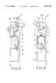
- FIGS. 9, 10, 11are schematic views illustrating the operation of the electromagnetic lock device
- FIGS. 12, 13are plane schematic views illustrating the other applications of the electromagnetic lock device.
- FIGS. 14, 15are top schematic views illustrating the operation of the electromagnetic lock device respectively.
- a cover 22is detachably secured to the front portion of the housing 20 and includes an orifice 221 formed therein for slidably receiving a latch 61 therein.
- a block 63is secured to the housing 20 and includes a pole 64 laterally extended therefrom and preferably perpendicular to the longitudinal axis of the housing 20. Alternatively, the pole 64 may be directly secured to or extended from the housing 20 instead of being extended from the block 63.
- the latch 61includes a bore 621 formed therein for slidably receiving the pole 64 and for allowing the latch 61 to be moved along the pole 64.
- the latch 61may also be slidably received in the housing 20 by the other guiding tracks or guiding channels or the like instead of the pole 64.
- the latch 61includes a cavity or an annular recess 620 formed therein and defined by an end stop 62; or includes a stud 611 of a reduced size extended therefrom and the end stop 62 secured to the free end of the stud 611 for defining the cavity or the annular recess 620.
- a follower 5includes a hole 53 formed therein for receiving the pin 211 of the housing 20 and for allowing the follower 5 to be rotatably or pivotally secured to the housing 20 at the pivot pin 211.
- the follower 5includes one or more pegs 52, 57 and an arm 51 extended therefrom.
- the arm 51preferably includes a head 511 formed on the free end thereof and engaged into the recess 620 of the latch 61 for moving the latch 61 inward and outward of the housing 20 when the follower 5 is rotated.
- the arm 51is located between the pegs 52, 57 and extended away from the pegs 52, 57. Or, the arm 51 and the pegs 52, 57 form a triangle.
- a casing 3is secured in the housing 20 and includes a coil 30 of an electromagnetic member therein and includes a puncture 31 formed in the upper portion thereof for slidably receiving a spindle 4 therein and includes an aperture 32 formed in the lower portion thereof for slidably receiving an extension 43 that is extended from the spindle 4 and that includes a size smaller than that of the spindle 4.
- the aperture 32includes a size smaller than that of the puncture 31 of the casing 3 for slidably receiving the extension 43 of the spindle 4 of the corresponding reduced size.
- the spindle 4 and/or the extension 43 of the spindle 4are slidably engaged in the coil 30 which is coupled to an electric power supply by electric wires 33.
- the spindle 4may be moved along a longitudinal direction by the coil 30 when the coil 30 is energized.
- the spindle 4includes a slot 45 formed in the upper portion thereof.
- a link 41includes a lower portion 412 received in the slot 45 of the spindle 4 and pivotally secured to the spindle 4 at a pivot axle 42 and includes an upper portion 411 that may be selectively coupled to either of the pegs 52, 57 of the follower 5 (FIGS. 3-6).
- the pivot axle 42preferably includes two ends extended outward of the spindle 4.
- a spring 44is engaged on the spindle 4 and engaged between the pivot axle 42 and the casing 3 for moving the spindle 4 upward when the coil 30 has not been energized. Alternatively, without the spring 44, the spindle 4 may also be actuated upward and downward by the coil 30.
- the latch 61may be moved inward of the housing 20 by the arm 51 of the follower 5 when the spindle 4 is biased upward by the spring 44 and when the coil 30 has not been energized.
- the latch 61may be moved outward of the housing 20 to lock the door 7 panel (FIG. 7) by the arm 51 of the follower 5 when the follower 5 is rotated clockwise by the spindle 4.
- the follower 5may be rotated counterclockwise when the spring 44 bias the spindle 4 upward.
- the housing 20may be secured in a door frame 71, and the latch 61 may be engaged into a lock hole that is formed in the door panel 7.
- the latch 61may be moved outward of the housing 20 to lock the door panel by the arm 51 of the follower 5 when the spindle 4 is biased upward by the spring 44 and when the coil 30 has not been energized.
- the latch 61may be moved inward of the housing 20 when the follower 5 is rotated in a reverse direction (counterclockwise) by the spindle 4.
- the follower 5may be rotated clockwise when the spring 44 bias the spindle 4 upward.
- the spaced distance between the pegs 52, 57 and the pin 211may be adjusted for adjusting the force applying onto the arm of the follower.
- the latch 61may include a tapered surface 613 formed therein and may include one or more flat surfaces 615 formed in the side portions.
- the latch 61may include a cylindrical shape as shown in FIG. 8.
- the orifice 221 of the cover 22may include one or more corresponding flat surfaces 223 formed therein for engaging with the flat surfaces 615 of the latch 61 and for preventing the latch 61 from rotating relative to the housing 20 and the cover 22, and for directing the moving direction of the latch 61.
- FIGS. 9 and 10when the latch 61 is biased outward of the housing 20 by the spring 44, the door panel 7 may be moved leftward to engage with the tapered surface 613 (FIG.
- the position of the housing 20may be changed to change the direction of the latch 61, such that the door panel 7 may engage with the tapered surface 613 of the latch 61 and may move the latch 61 inward of the housing 20 when the door panel 7 is moved rightward.
- the housing of the electromagnetic lock devicemay also be disposed between the door frame 71 and the door panel 7 in a direction different from that shown in FIGS. 9-11.
- the door panel 7may also engage with the tapered surface 613 of the latch 61 and may move the latch 61 inward of the housing 20 when the door panel 7 is moved inward (FIGS. 12, 14 from outside of the building) or may move the latch 61 inward of the housing 20 when the door panel 7 is moved outward (FIGS. 13, 15 from inside of the building).
- the electromagnetic lock device in accordance with the present inventionincludes a latch 1indirectly coupled to and actuated by the electromagnetic device.
- the actuation direction of the latchmay be changed and selectively actuated by the electromagnetic device.
Landscapes
- Physics & Mathematics (AREA)
- Electromagnetism (AREA)
- Lock And Its Accessories (AREA)
Abstract
Description
1. Field of the Invention
The present invention relates to a lock, and more particularly to an electromagnetic lock device.
2. Description of the Prior Art
Typical electromagnetic lock devices comprise a spindle slidably received in an electromagnetic member, such as engaged in a coil of the electromagnetic member so as to be moved by the electromagnetic member. The spindle of some of the lock devices are directly used to latch the doors or the like. The other lock devices include a latch directly moved by the spindle so as to lock the doors or the like. The typical electromagnetic lock devices may not be effectively operated.
The present invention has arisen to mitigate and/or obviate the afore-described disadvantages of the conventional electromagnetic lock devices.
The primary objective of the present invention is to provide an electromagnetic lock device which includes a latch indirectly coupled to and actuated by the electromagnetic device.
The other objective of the present invention is to provide an electromagnetic lock device which includes a latch having an actuation direction that may be changed and selectively actuated by the electromagnetic device.
In accordance with one aspect of the invention, there is provided an electromagnetic lock device comprising a housing, a latch slidably received in the housing, a follower rotatably secured to the housing at a pivot pin, the follower including an arm extended therefrom and engaged with the latch for moving the latch inward and outward of the housing, the follower including a first peg extended therefrom, an electromagnetic member secured in the housing and including a coil, a spindle slidably engaged in and actuated by the coil, means for coupling the spindle to the first peg of the follower. The spindle may be actuated to move along the coil in either of the direction by the coil when the coil is energized. The follower is rotated in a first direction, by the spindle, to move the latch inward of the housing and is rotated in a reverse direction to move the latch outward of the housing.
The latch includes a bore formed therein, the housing includes a pole extended therefrom and engaged into the bore of the latch for guiding the latch to move along the pole. The housing includes a block secured thereto, the pole is extended from the block.
The latch includes a recess formed therein for receiving the arm of the follower and for allowing the arm of the follower to move the latch inward and outward of the housing. The recess of the latch may be an annular recess. The arm of the follower includes a head formed thereon and engaged in the recess of the latch.
A guiding means is further provided for guiding the latch to move relative to the housing and includes a first flat surface formed in the latch, a cover secured to the housing and having a second flat surface formed therein and engaged with the first flat surface of the latch, the latch is prevented from rotating relative to the housing and the cover by the engagement between the first flat surface of the latch and the second flat surface of the cover.
The follower further includes a second peg extended therefrom, the coupling means couples the spindle to the second peg of the follower for allowing the follower to be rotated in the first direction to move the latch outward of the housing and to be rotated in the reverse direction to move the latch inward of the housing. The coupling means includes a link having a first end pivotally coupled to the spindle at a pivot axle and having a second end pivotally coupled to the first peg.
The spindle includes an extension extended therefrom. A casing is further secured in the housing for receiving the coil. The extension of the spindle includes a size smaller than that of the spindle, the casing includes a puncture formed therein for slidably receiving the spindle and includes an aperture formed therein for slidably receiving the extension of the spindle, the aperture of the casing includes a size smaller than that of the puncture of the casing.
A spring biasing device is further provided for biasing said spindle toward said follower and to rotate said follower and thus to actuate the latch.
Further objectives and advantages of the present invention will become apparent from a careful reading of a detailed description provided hereinbelow, with appropriate reference to accompanying drawings.
FIG. 1 is an exploded view of an electromagnetic lock device in accordance with the present invention;
FIG. 2 is a partial exploded view of the electromagnetic lock device;
FIGS. 3, 4, 5, 6 are plane schematic views illustrating the operation of the electromagnetic lock device;
FIG. 7 is a plane schematic view illustrating the attachment of the electromagnetic lock device to a door;
FIG. 8 is an exploded view illustrating the other embodiment of the electromagnetic lock device;
FIGS. 9, 10, 11 are schematic views illustrating the operation of the electromagnetic lock device;
FIGS. 12, 13 are plane schematic views illustrating the other applications of the electromagnetic lock device; and
FIGS. 14, 15 are top schematic views illustrating the operation of the electromagnetic lock device respectively.
Referring to the drawings, and initially to FIGS. 1-3, an electromagnetic lock device in accordance with the present invention comprises ahousing 20 including aseat 21 having apin 211 extended therefrom and including acap 23 detachably secured to the side portion thereof for enclosing thehousing 20 and for retaining the elements within thehousing 20. Acover 22 is detachably secured to the front portion of thehousing 20 and includes anorifice 221 formed therein for slidably receiving alatch 61 therein. Ablock 63 is secured to thehousing 20 and includes apole 64 laterally extended therefrom and preferably perpendicular to the longitudinal axis of thehousing 20. Alternatively, thepole 64 may be directly secured to or extended from thehousing 20 instead of being extended from theblock 63. Thelatch 61 includes abore 621 formed therein for slidably receiving thepole 64 and for allowing thelatch 61 to be moved along thepole 64. Alternatively, thelatch 61 may also be slidably received in thehousing 20 by the other guiding tracks or guiding channels or the like instead of thepole 64. Thelatch 61 includes a cavity or anannular recess 620 formed therein and defined by anend stop 62; or includes astud 611 of a reduced size extended therefrom and theend stop 62 secured to the free end of thestud 611 for defining the cavity or theannular recess 620.
Afollower 5 includes ahole 53 formed therein for receiving thepin 211 of thehousing 20 and for allowing thefollower 5 to be rotatably or pivotally secured to thehousing 20 at thepivot pin 211. Thefollower 5 includes one ormore pegs arm 51 extended therefrom. Thearm 51 preferably includes ahead 511 formed on the free end thereof and engaged into therecess 620 of thelatch 61 for moving thelatch 61 inward and outward of thehousing 20 when thefollower 5 is rotated. As shown in the drawings, it is preferable that twopegs follower 5 and are spaced away from each other and are spaced from thepivot pin 211 or thehole 53 of thefollower 5. Thearm 51 is located between thepegs pegs arm 51 and thepegs
Acasing 3 is secured in thehousing 20 and includes acoil 30 of an electromagnetic member therein and includes apuncture 31 formed in the upper portion thereof for slidably receiving aspindle 4 therein and includes anaperture 32 formed in the lower portion thereof for slidably receiving anextension 43 that is extended from thespindle 4 and that includes a size smaller than that of thespindle 4. Theaperture 32 includes a size smaller than that of thepuncture 31 of thecasing 3 for slidably receiving theextension 43 of thespindle 4 of the corresponding reduced size. Thespindle 4 and/or theextension 43 of thespindle 4 are slidably engaged in thecoil 30 which is coupled to an electric power supply byelectric wires 33. Thespindle 4 may be moved along a longitudinal direction by thecoil 30 when thecoil 30 is energized. Thespindle 4 includes aslot 45 formed in the upper portion thereof. Alink 41 includes alower portion 412 received in theslot 45 of thespindle 4 and pivotally secured to thespindle 4 at apivot axle 42 and includes anupper portion 411 that may be selectively coupled to either of thepegs pivot axle 42 preferably includes two ends extended outward of thespindle 4. Aspring 44 is engaged on thespindle 4 and engaged between thepivot axle 42 and thecasing 3 for moving thespindle 4 upward when thecoil 30 has not been energized. Alternatively, without thespring 44, thespindle 4 may also be actuated upward and downward by thecoil 30.
In operation, as shown in FIG. 4, when theupper portion 411 of thelink 41 is coupled to thepeg 52 of thefollower 5, for example, thelatch 61 may be moved inward of thehousing 20 by thearm 51 of thefollower 5 when thespindle 4 is biased upward by thespring 44 and when thecoil 30 has not been energized. As shown in FIG. 3, when thecoil 30 is energized to move thespindle 4 downward against thespring 44, thelatch 61 may be moved outward of thehousing 20 to lock thedoor 7 panel (FIG. 7) by thearm 51 of thefollower 5 when thefollower 5 is rotated clockwise by thespindle 4. Thefollower 5 may be rotated counterclockwise when thespring 44 bias thespindle 4 upward. Thehousing 20 may be secured in adoor frame 71, and thelatch 61 may be engaged into a lock hole that is formed in thedoor panel 7.
As shown in FIG. 5, alternatively, when theupper portion 411 of thelink 41 is coupled to theother peg 57 of thefollower 5, thelatch 61 may be moved outward of thehousing 20 to lock the door panel by thearm 51 of thefollower 5 when thespindle 4 is biased upward by thespring 44 and when thecoil 30 has not been energized. As shown in FIG. 6, when thecoil 30 is energized to move thespindle 4 downward against thespring 44, thelatch 61 may be moved inward of thehousing 20 when thefollower 5 is rotated in a reverse direction (counterclockwise) by thespindle 4. Thefollower 5 may be rotated clockwise when thespring 44 bias thespindle 4 upward. The spaced distance between thepegs pin 211 may be adjusted for adjusting the force applying onto the arm of the follower.
Thelatch 61 may include atapered surface 613 formed therein and may include one or moreflat surfaces 615 formed in the side portions. Alternatively, thelatch 61 may include a cylindrical shape as shown in FIG. 8. Theorifice 221 of thecover 22 may include one or more correspondingflat surfaces 223 formed therein for engaging with theflat surfaces 615 of thelatch 61 and for preventing thelatch 61 from rotating relative to thehousing 20 and thecover 22, and for directing the moving direction of thelatch 61. As shown in FIGS. 9 and 10, when thelatch 61 is biased outward of thehousing 20 by thespring 44, thedoor panel 7 may be moved leftward to engage with the tapered surface 613 (FIG. 9) of thelatch 61 to move thelatch 61 inward of thehousing 20 until thelatch 61 is biased to engage with thelock hole 77 of thedoor panel 7. Alternatively, as shown in FIG. 11, the position of thehousing 20 may be changed to change the direction of thelatch 61, such that thedoor panel 7 may engage with thetapered surface 613 of thelatch 61 and may move thelatch 61 inward of thehousing 20 when thedoor panel 7 is moved rightward.
Referring next to FIGS. 12-15, the housing of the electromagnetic lock device may also be disposed between thedoor frame 71 and thedoor panel 7 in a direction different from that shown in FIGS. 9-11. Thedoor panel 7 may also engage with thetapered surface 613 of thelatch 61 and may move thelatch 61 inward of thehousing 20 when thedoor panel 7 is moved inward (FIGS. 12, 14 from outside of the building) or may move thelatch 61 inward of thehousing 20 when thedoor panel 7 is moved outward (FIGS. 13, 15 from inside of the building).
Accordingly, the electromagnetic lock device in accordance with the present invention includes a latch 1indirectly coupled to and actuated by the electromagnetic device. In addition, the actuation direction of the latch may be changed and selectively actuated by the electromagnetic device.
Although this invention has been described with a certain degree of particularity, it is to be understood that the present disclosure has been made by way of example only and that numerous changes in the detailed construction and the combination and arrangement of parts may be resorted to without departing from the spirit and scope of the invention as hereinafter claimed.
Claims (12)
1. An electromagnetic lock device comprising:
a housing including a pole extended therefrom,
a latch slidably received in said housing, said latch including a bore formed therein for slidably receiving said pole of said housing and for guiding said latch to move along said pole,
a follower rotatably secured to said housing at a pivot pin, said follower including an arm extended therefrom and engaged with said latch for moving said latch inward and outward of said housing, said follower including a first peg extended therefrom,
an electromagnetic member secured in said housing and including a coil,
a spindle slidably engaged in and actuated by said coil,
means for coupling said spindle to said first peg of said follower,
said follower being rotated in a first direction to move said latch inward of said housing and being rotated in a reverse direction to move said latch outward of said housing.
2. The electromagnetic lock device according to claim 1, wherein said housing includes a block secured thereto, said pole is extended from said block.
3. The electromagnetic lock device according to claim 1, wherein said latch includes a recess formed therein for receiving said arm of said follower and for allowing said arm of said follower to move said latch inward and outward of said housing.
4. The electromagnetic lock device according to claim 3, wherein said recess of said latch is an annular recess.
5. The electromagnetic lock device according to claim 3, wherein said arm of said follower includes a head formed thereon and engaged in said recess of said latch.
6. The electromagnetic lock device according to claim 1 further comprising means for guiding said latch to move relative to said housing.
7. The electromagnetic lock device according to claim 6, wherein said guiding means includes a first flat surface formed in said latch, a cover secured to said housing and having a second flat surface formed therein and engaged with said first flat surface of said latch, said latch is prevented from rotating relative to said housing and said cover by the engagement between said first flat surface of said latch and said second flat surface of said cover.
8. The electromagnetic lock device according to claim 1, wherein said coupling means includes a link having a first end pivotally coupled to said spindle at a pivot axle and having a second end pivotally coupled to said first peg.
9. The electromagnetic lock device according to claim 1, wherein said spindle includes an extension extended therefrom.
10. The electromagnetic lock device according to claim 9 further comprising a casing secured in said housing, said coil being secured in said casing, said extension of said spindle including a diameter that is smaller than that of said spindle, said casing including a puncture formed therein for slidably receiving said spindle and including an aperture formed therein for slidably receiving said extension of said spindle, said aperture of said casing including a diameter that is smaller than that of said puncture of said casing.
11. The electromagnetic lock device according to claim 1 further comprising means for biasing said spindle toward said follower and to rotate said follower.
12. An electromagnetic lock device comprising:
a housing,
a latch slidably received in said housing,
a follower rotatably secured to said housing at a pivot pin, said follower including an arm extended therefrom and engaged with said latch for moving said latch inward and outward of said housing, said follower including a first peg extended therefrom,
an electromagnetic member secured in said housing and including a coil,
a spindle slidably engaged in and actuated by said coil,
means for coupling said srindle to said first peg of said follower,
said follower being rotated in a first direction to move said latch inward of said housing and being rotated in a reverse direction to move said latch outward of said housing,
wherein said follower further includes a second peg extended therefrom, said coupling means couples said spindle to said second peg of said follower when said spindle is disengaged from said first peg, for allowing said follower to be rotated in said first direction to move said latch outward of said housing and to be rotated in the reverse direction to move said latch inward of said housing.
Priority Applications (1)
| Application Number | Priority Date | Filing Date | Title |
|---|---|---|---|
| US09/327,000US6079755A (en) | 1999-06-07 | 1999-06-07 | Electromagnetic lock device |
Applications Claiming Priority (1)
| Application Number | Priority Date | Filing Date | Title |
|---|---|---|---|
| US09/327,000US6079755A (en) | 1999-06-07 | 1999-06-07 | Electromagnetic lock device |
Publications (1)
| Publication Number | Publication Date |
|---|---|
| US6079755Atrue US6079755A (en) | 2000-06-27 |
Family
ID=23274698
Family Applications (1)
| Application Number | Title | Priority Date | Filing Date |
|---|---|---|---|
| US09/327,000Expired - Fee RelatedUS6079755A (en) | 1999-06-07 | 1999-06-07 | Electromagnetic lock device |
Country Status (1)
| Country | Link |
|---|---|
| US (1) | US6079755A (en) |
Cited By (70)
| Publication number | Priority date | Publication date | Assignee | Title |
|---|---|---|---|---|
| WO2001021915A1 (en)* | 1999-09-23 | 2001-03-29 | Gerhardt John M | An electromagnetic locking device |
| US6581333B2 (en)* | 2001-03-08 | 2003-06-24 | The Bratton Corporation | Frame mounting for prison door lock and method employing same |
| US6601418B2 (en)* | 2001-09-04 | 2003-08-05 | Tsun Thin Huang | Structure for electric lock |
| US6619085B1 (en)* | 2002-09-12 | 2003-09-16 | Hui-Hua Hsieh | Remote-controlled lock |
| US6698263B2 (en)* | 2002-07-22 | 2004-03-02 | Hui-Hua Hsieh | Remote-controlled door lock |
| US20050011238A1 (en)* | 2003-06-06 | 2005-01-20 | Benoit Roberge | Electronic locking system |
| US20050012343A1 (en)* | 2003-07-18 | 2005-01-20 | Mark Warden | Electronic door lock dogging mechanism |
| US20050183480A1 (en)* | 2002-08-19 | 2005-08-25 | Hingston Neil R. | Electric lock |
| US20060042334A1 (en)* | 2004-09-01 | 2006-03-02 | Huang Chien Y | Electromagnetic lock device |
| US7017379B1 (en)* | 2004-11-22 | 2006-03-28 | Hui-Hua Hsieh | Remote-controlled burglary preventing door lock |
| US20060201214A1 (en)* | 2001-10-22 | 2006-09-14 | Ulrich Bantle | Lock |
| US20060284428A1 (en)* | 2005-06-13 | 2006-12-21 | Darryl Beadle | High reliability gate lock for exterior use |
| US7237412B1 (en)* | 2005-05-17 | 2007-07-03 | Soca Technology Co., Ltd. | All purpose type deadbolt lock |
| US20080244984A1 (en)* | 2004-06-28 | 2008-10-09 | Brian Owen Kelly | Door Jamb Finger Guard |
| US20090282875A1 (en)* | 2008-05-19 | 2009-11-19 | Robert John Olmsted | Method and Apparatus Pertaining to Selectively Blocking a Lock Hasp |
| US8080000B2 (en) | 2004-04-21 | 2011-12-20 | Acclarent, Inc. | Methods and apparatus for treating disorders of the ear nose and throat |
| US8088101B2 (en) | 2004-04-21 | 2012-01-03 | Acclarent, Inc. | Devices, systems and methods for treating disorders of the ear, nose and throat |
| US8100933B2 (en) | 2002-09-30 | 2012-01-24 | Acclarent, Inc. | Method for treating obstructed paranasal frontal sinuses |
| US8114113B2 (en) | 2005-09-23 | 2012-02-14 | Acclarent, Inc. | Multi-conduit balloon catheter |
| US8114062B2 (en) | 2004-04-21 | 2012-02-14 | Acclarent, Inc. | Devices and methods for delivering therapeutic substances for the treatment of sinusitis and other disorders |
| US8118757B2 (en) | 2007-04-30 | 2012-02-21 | Acclarent, Inc. | Methods and devices for ostium measurement |
| US8142422B2 (en) | 2004-04-21 | 2012-03-27 | Acclarent, Inc. | Devices, systems and methods for diagnosing and treating sinusitis and other disorders of the ears, nose and/or throat |
| US8146400B2 (en) | 2004-04-21 | 2012-04-03 | Acclarent, Inc. | Endoscopic methods and devices for transnasal procedures |
| US8172828B2 (en) | 2004-04-21 | 2012-05-08 | Acclarent, Inc. | Apparatus and methods for dilating and modifying ostia of paranasal sinuses and other intranasal or paranasal structures |
| US8182432B2 (en) | 2008-03-10 | 2012-05-22 | Acclarent, Inc. | Corewire design and construction for medical devices |
| US8190389B2 (en) | 2006-05-17 | 2012-05-29 | Acclarent, Inc. | Adapter for attaching electromagnetic image guidance components to a medical device |
| US8388642B2 (en) | 2005-01-18 | 2013-03-05 | Acclarent, Inc. | Implantable devices and methods for treating sinusitis and other disorders |
| US8414473B2 (en) | 2004-04-21 | 2013-04-09 | Acclarent, Inc. | Methods and apparatus for treating disorders of the ear nose and throat |
| US8435290B2 (en) | 2009-03-31 | 2013-05-07 | Acclarent, Inc. | System and method for treatment of non-ventilating middle ear by providing a gas pathway through the nasopharynx |
| US8439687B1 (en) | 2006-12-29 | 2013-05-14 | Acclarent, Inc. | Apparatus and method for simulated insertion and positioning of guidewares and other interventional devices |
| US8485199B2 (en) | 2007-05-08 | 2013-07-16 | Acclarent, Inc. | Methods and devices for protecting nasal turbinate during surgery |
| US8702626B1 (en) | 2004-04-21 | 2014-04-22 | Acclarent, Inc. | Guidewires for performing image guided procedures |
| US8715169B2 (en) | 2004-04-21 | 2014-05-06 | Acclarent, Inc. | Devices, systems and methods useable for treating sinusitis |
| US8740929B2 (en) | 2001-02-06 | 2014-06-03 | Acclarent, Inc. | Spacing device for releasing active substances in the paranasal sinus |
| US8747389B2 (en) | 2004-04-21 | 2014-06-10 | Acclarent, Inc. | Systems for treating disorders of the ear, nose and throat |
| US8764729B2 (en) | 2004-04-21 | 2014-07-01 | Acclarent, Inc. | Frontal sinus spacer |
| US8864787B2 (en) | 2004-04-21 | 2014-10-21 | Acclarent, Inc. | Ethmoidotomy system and implantable spacer devices having therapeutic substance delivery capability for treatment of paranasal sinusitis |
| US8894614B2 (en) | 2004-04-21 | 2014-11-25 | Acclarent, Inc. | Devices, systems and methods useable for treating frontal sinusitis |
| US8932276B1 (en) | 2004-04-21 | 2015-01-13 | Acclarent, Inc. | Shapeable guide catheters and related methods |
| US8951225B2 (en) | 2005-06-10 | 2015-02-10 | Acclarent, Inc. | Catheters with non-removable guide members useable for treatment of sinusitis |
| US8979888B2 (en) | 2008-07-30 | 2015-03-17 | Acclarent, Inc. | Paranasal ostium finder devices and methods |
| US9039680B2 (en) | 2004-08-04 | 2015-05-26 | Acclarent, Inc. | Implantable devices and methods for delivering drugs and other substances to treat sinusitis and other disorders |
| US9072626B2 (en) | 2009-03-31 | 2015-07-07 | Acclarent, Inc. | System and method for treatment of non-ventilating middle ear by providing a gas pathway through the nasopharynx |
| US9089258B2 (en) | 2004-04-21 | 2015-07-28 | Acclarent, Inc. | Endoscopic methods and devices for transnasal procedures |
| US9101384B2 (en) | 2004-04-21 | 2015-08-11 | Acclarent, Inc. | Devices, systems and methods for diagnosing and treating sinusitis and other disorders of the ears, Nose and/or throat |
| US9107574B2 (en) | 2004-04-21 | 2015-08-18 | Acclarent, Inc. | Endoscopic methods and devices for transnasal procedures |
| US20150267442A1 (en)* | 2014-03-19 | 2015-09-24 | Digilock Asia Ltd. | Secure Solenoid Driven Deadbolt Lock |
| US9155492B2 (en) | 2010-09-24 | 2015-10-13 | Acclarent, Inc. | Sinus illumination lightwire device |
| US9265407B2 (en) | 2004-04-21 | 2016-02-23 | Acclarent, Inc. | Endoscopic methods and devices for transnasal procedures |
| CN105447966A (en)* | 2016-01-06 | 2016-03-30 | 上海古鳌电子科技股份有限公司 | Cash receiving box locking apparatus |
| US9351750B2 (en) | 2004-04-21 | 2016-05-31 | Acclarent, Inc. | Devices and methods for treating maxillary sinus disease |
| US9399121B2 (en) | 2004-04-21 | 2016-07-26 | Acclarent, Inc. | Systems and methods for transnasal dilation of passageways in the ear, nose or throat |
| US9433437B2 (en) | 2013-03-15 | 2016-09-06 | Acclarent, Inc. | Apparatus and method for treatment of ethmoid sinusitis |
| US9468362B2 (en) | 2004-04-21 | 2016-10-18 | Acclarent, Inc. | Endoscopic methods and devices for transnasal procedures |
| US9629684B2 (en) | 2013-03-15 | 2017-04-25 | Acclarent, Inc. | Apparatus and method for treatment of ethmoid sinusitis |
| CN106639659A (en)* | 2016-12-21 | 2017-05-10 | 周正刚 | Push-draw mode electromagnetic lock |
| US20170297817A1 (en)* | 2013-01-25 | 2017-10-19 | Serio-Us Industries, Inc. | Container with automatic latch assembly |
| US9820688B2 (en) | 2006-09-15 | 2017-11-21 | Acclarent, Inc. | Sinus illumination lightwire device |
| US20180179789A1 (en)* | 2016-12-27 | 2018-06-28 | Cebi Italy S.P.A. | Closing device of a fuel tank lid for vehicles |
| EP3404245A1 (en)* | 2017-05-19 | 2018-11-21 | Goodrich Actuation Systems Limited | Tertiary lock system for a thrust reverser |
| US20180345906A1 (en)* | 2017-05-23 | 2018-12-06 | Gogoro Inc. | Lock apparatus and vehicle using the same |
| US10188413B1 (en) | 2004-04-21 | 2019-01-29 | Acclarent, Inc. | Deflectable guide catheters and related methods |
| US10206821B2 (en) | 2007-12-20 | 2019-02-19 | Acclarent, Inc. | Eustachian tube dilation balloon with ventilation path |
| US10524814B2 (en) | 2009-03-20 | 2020-01-07 | Acclarent, Inc. | Guide system with suction |
| US11065061B2 (en) | 2004-04-21 | 2021-07-20 | Acclarent, Inc. | Systems and methods for performing image guided procedures within the ear, nose, throat and paranasal sinuses |
| US11124989B2 (en)* | 2016-09-19 | 2021-09-21 | Level Home, Inc. | Deadbolt extension device for an electromechanical lock |
| US11529502B2 (en) | 2004-04-21 | 2022-12-20 | Acclarent, Inc. | Apparatus and methods for dilating and modifying ostia of paranasal sinuses and other intranasal or paranasal structures |
| US11680425B2 (en)* | 2019-09-18 | 2023-06-20 | Elbee Pty Ltd. | Magnet responsive cabinet lock |
| US20240076908A1 (en)* | 2022-09-01 | 2024-03-07 | Kdb Intellectual Pty Ltd | Multi-lock comprising a keyless lock for closures |
| EP4488481A4 (en)* | 2022-11-24 | 2025-07-02 | Shanghai Shanmai Electronic Tech Development Co Ltd | LOCK |
Citations (6)
| Publication number | Priority date | Publication date | Assignee | Title |
|---|---|---|---|---|
| US2798751A (en)* | 1955-11-23 | 1957-07-09 | John E Walden | Electrically actuated lock mechanism |
| US3901542A (en)* | 1974-10-23 | 1975-08-26 | Robert Stephen Salzman | Retro-fit lock kit and method of installing same |
| US4909053A (en)* | 1988-05-17 | 1990-03-20 | Liberty Telephone Communications, Inc. | High security door locking device |
| US5044678A (en)* | 1990-07-25 | 1991-09-03 | Lectron Products, Inc. | Solenoid operated latch device with movable pole piece |
| US5386713A (en)* | 1991-03-07 | 1995-02-07 | Wilson; Bert | Remote control car deadbolt lock |
| US5531086A (en)* | 1994-08-15 | 1996-07-02 | Bryant; Randy K. | Keyless entry deadbolt lock |
- 1999
- 1999-06-07USUS09/327,000patent/US6079755A/ennot_activeExpired - Fee Related
Patent Citations (6)
| Publication number | Priority date | Publication date | Assignee | Title |
|---|---|---|---|---|
| US2798751A (en)* | 1955-11-23 | 1957-07-09 | John E Walden | Electrically actuated lock mechanism |
| US3901542A (en)* | 1974-10-23 | 1975-08-26 | Robert Stephen Salzman | Retro-fit lock kit and method of installing same |
| US4909053A (en)* | 1988-05-17 | 1990-03-20 | Liberty Telephone Communications, Inc. | High security door locking device |
| US5044678A (en)* | 1990-07-25 | 1991-09-03 | Lectron Products, Inc. | Solenoid operated latch device with movable pole piece |
| US5386713A (en)* | 1991-03-07 | 1995-02-07 | Wilson; Bert | Remote control car deadbolt lock |
| US5531086A (en)* | 1994-08-15 | 1996-07-02 | Bryant; Randy K. | Keyless entry deadbolt lock |
Cited By (155)
| Publication number | Priority date | Publication date | Assignee | Title |
|---|---|---|---|---|
| WO2001021915A1 (en)* | 1999-09-23 | 2001-03-29 | Gerhardt John M | An electromagnetic locking device |
| US8740929B2 (en) | 2001-02-06 | 2014-06-03 | Acclarent, Inc. | Spacing device for releasing active substances in the paranasal sinus |
| US6581333B2 (en)* | 2001-03-08 | 2003-06-24 | The Bratton Corporation | Frame mounting for prison door lock and method employing same |
| US6601418B2 (en)* | 2001-09-04 | 2003-08-05 | Tsun Thin Huang | Structure for electric lock |
| US20060201214A1 (en)* | 2001-10-22 | 2006-09-14 | Ulrich Bantle | Lock |
| US6698263B2 (en)* | 2002-07-22 | 2004-03-02 | Hui-Hua Hsieh | Remote-controlled door lock |
| US20050183480A1 (en)* | 2002-08-19 | 2005-08-25 | Hingston Neil R. | Electric lock |
| US6619085B1 (en)* | 2002-09-12 | 2003-09-16 | Hui-Hua Hsieh | Remote-controlled lock |
| US9457175B2 (en) | 2002-09-30 | 2016-10-04 | Acclarent, Inc. | Balloon catheters and methods for treating paranasal sinuses |
| US8764786B2 (en) | 2002-09-30 | 2014-07-01 | Acclarent, Inc. | Balloon catheters and methods for treating paranasal sinuses |
| US8100933B2 (en) | 2002-09-30 | 2012-01-24 | Acclarent, Inc. | Method for treating obstructed paranasal frontal sinuses |
| US8317816B2 (en) | 2002-09-30 | 2012-11-27 | Acclarent, Inc. | Balloon catheters and methods for treating paranasal sinuses |
| US20050011238A1 (en)* | 2003-06-06 | 2005-01-20 | Benoit Roberge | Electronic locking system |
| US20050012343A1 (en)* | 2003-07-18 | 2005-01-20 | Mark Warden | Electronic door lock dogging mechanism |
| US7055871B2 (en)* | 2003-07-18 | 2006-06-06 | Jackson Corp. | Electronic door lock dogging mechanism |
| US9241834B2 (en) | 2004-04-21 | 2016-01-26 | Acclarent, Inc. | Devices, systems and methods for treating disorders of the ear, nose and throat |
| US10500380B2 (en) | 2004-04-21 | 2019-12-10 | Acclarent, Inc. | Devices, systems and methods useable for treating sinusitis |
| US8080000B2 (en) | 2004-04-21 | 2011-12-20 | Acclarent, Inc. | Methods and apparatus for treating disorders of the ear nose and throat |
| US8090433B2 (en) | 2004-04-21 | 2012-01-03 | Acclarent, Inc. | Methods and apparatus for treating disorders of the ear nose and throat |
| US8088101B2 (en) | 2004-04-21 | 2012-01-03 | Acclarent, Inc. | Devices, systems and methods for treating disorders of the ear, nose and throat |
| US11957318B2 (en) | 2004-04-21 | 2024-04-16 | Acclarent, Inc. | Methods and apparatus for treating disorders of the ear nose and throat |
| US11864725B2 (en) | 2004-04-21 | 2024-01-09 | Acclarent, Inc. | Devices, systems and methods for diagnosing and treating sinusitis and other disorders of the ears, nose and/or throat |
| US8114062B2 (en) | 2004-04-21 | 2012-02-14 | Acclarent, Inc. | Devices and methods for delivering therapeutic substances for the treatment of sinusitis and other disorders |
| US11589742B2 (en) | 2004-04-21 | 2023-02-28 | Acclarent, Inc. | Methods and apparatus for treating disorders of the ear nose and throat |
| US8123722B2 (en) | 2004-04-21 | 2012-02-28 | Acclarent, Inc. | Devices, systems and methods for treating disorders of the ear, nose and throat |
| US11529502B2 (en) | 2004-04-21 | 2022-12-20 | Acclarent, Inc. | Apparatus and methods for dilating and modifying ostia of paranasal sinuses and other intranasal or paranasal structures |
| US8142422B2 (en) | 2004-04-21 | 2012-03-27 | Acclarent, Inc. | Devices, systems and methods for diagnosing and treating sinusitis and other disorders of the ears, nose and/or throat |
| US8146400B2 (en) | 2004-04-21 | 2012-04-03 | Acclarent, Inc. | Endoscopic methods and devices for transnasal procedures |
| US8172828B2 (en) | 2004-04-21 | 2012-05-08 | Acclarent, Inc. | Apparatus and methods for dilating and modifying ostia of paranasal sinuses and other intranasal or paranasal structures |
| US11511090B2 (en) | 2004-04-21 | 2022-11-29 | Acclarent, Inc. | Devices, systems and methods useable for treating sinusitis |
| US11202644B2 (en) | 2004-04-21 | 2021-12-21 | Acclarent, Inc. | Shapeable guide catheters and related methods |
| US11065061B2 (en) | 2004-04-21 | 2021-07-20 | Acclarent, Inc. | Systems and methods for performing image guided procedures within the ear, nose, throat and paranasal sinuses |
| US11020136B2 (en) | 2004-04-21 | 2021-06-01 | Acclarent, Inc. | Deflectable guide catheters and related methods |
| US8414473B2 (en) | 2004-04-21 | 2013-04-09 | Acclarent, Inc. | Methods and apparatus for treating disorders of the ear nose and throat |
| US8425457B2 (en) | 2004-04-21 | 2013-04-23 | Acclarent, Inc. | Devices, systems and methods for diagnosing and treating sinusitus and other disorder of the ears, nose and/or throat |
| US11019989B2 (en) | 2004-04-21 | 2021-06-01 | Acclarent, Inc. | Methods and apparatus for treating disorders of the ear nose and throat |
| US10874838B2 (en) | 2004-04-21 | 2020-12-29 | Acclarent, Inc. | Systems and methods for transnasal dilation of passageways in the ear, nose or throat |
| US10856727B2 (en) | 2004-04-21 | 2020-12-08 | Acclarent, Inc. | Endoscopic methods and devices for transnasal procedures |
| US8702626B1 (en) | 2004-04-21 | 2014-04-22 | Acclarent, Inc. | Guidewires for performing image guided procedures |
| US8715169B2 (en) | 2004-04-21 | 2014-05-06 | Acclarent, Inc. | Devices, systems and methods useable for treating sinusitis |
| US8721591B2 (en) | 2004-04-21 | 2014-05-13 | Acclarent, Inc. | Apparatus and methods for dilating and modifying ostia of paranasal sinuses and other intranasal or paranasal structures |
| US10806477B2 (en) | 2004-04-21 | 2020-10-20 | Acclarent, Inc. | Systems and methods for transnasal dilation of passageways in the ear, nose or throat |
| US8747389B2 (en) | 2004-04-21 | 2014-06-10 | Acclarent, Inc. | Systems for treating disorders of the ear, nose and throat |
| US10779752B2 (en) | 2004-04-21 | 2020-09-22 | Acclarent, Inc. | Guidewires for performing image guided procedures |
| US8764726B2 (en) | 2004-04-21 | 2014-07-01 | Acclarent, Inc. | Devices, systems and methods useable for treating sinusitis |
| US8764709B2 (en) | 2004-04-21 | 2014-07-01 | Acclarent, Inc. | Devices, systems and methods for treating disorders of the ear, nose and throat |
| US8764729B2 (en) | 2004-04-21 | 2014-07-01 | Acclarent, Inc. | Frontal sinus spacer |
| US8777926B2 (en) | 2004-04-21 | 2014-07-15 | Acclarent, Inc. | Apparatus and methods for dilating and modifying ostia of paranasal sinuses and other intranasel or paranasal structures |
| US8828041B2 (en) | 2004-04-21 | 2014-09-09 | Acclarent, Inc. | Devices, systems and methods useable for treating sinusitis |
| US8852143B2 (en) | 2004-04-21 | 2014-10-07 | Acclarent, Inc. | Devices, systems and methods for treating disorders of the ear, nose and throat |
| US8858586B2 (en) | 2004-04-21 | 2014-10-14 | Acclarent, Inc. | Methods for enlarging ostia of paranasal sinuses |
| US8864787B2 (en) | 2004-04-21 | 2014-10-21 | Acclarent, Inc. | Ethmoidotomy system and implantable spacer devices having therapeutic substance delivery capability for treatment of paranasal sinusitis |
| US8870893B2 (en) | 2004-04-21 | 2014-10-28 | Acclarent, Inc. | Devices, systems and methods for diagnosing and treating sinusitis and other disorders of the ears, nose and/or throat |
| US8894614B2 (en) | 2004-04-21 | 2014-11-25 | Acclarent, Inc. | Devices, systems and methods useable for treating frontal sinusitis |
| US8905922B2 (en) | 2004-04-21 | 2014-12-09 | Acclarent, Inc. | Devices, systems and methods for diagnosing and treating sinusitis and other disorders of the ears, nose and/or throat |
| US8932276B1 (en) | 2004-04-21 | 2015-01-13 | Acclarent, Inc. | Shapeable guide catheters and related methods |
| US8945088B2 (en) | 2004-04-21 | 2015-02-03 | Acclarent, Inc. | Apparatus and methods for dilating and modifying ostia of paranasal sinuses and other intranasal or paranasal structures |
| US10702295B2 (en) | 2004-04-21 | 2020-07-07 | Acclarent, Inc. | Methods and apparatus for treating disorders of the ear nose and throat |
| US8961398B2 (en) | 2004-04-21 | 2015-02-24 | Acclarent, Inc. | Methods and apparatus for treating disorders of the ear, nose and throat |
| US8961495B2 (en) | 2004-04-21 | 2015-02-24 | Acclarent, Inc. | Devices, systems and methods for treating disorders of the ear, nose and throat |
| US10695080B2 (en) | 2004-04-21 | 2020-06-30 | Acclarent, Inc. | Devices, systems and methods for diagnosing and treating sinusitis and other disorders of the ears, nose and/or throat |
| US10631756B2 (en) | 2004-04-21 | 2020-04-28 | Acclarent, Inc. | Guidewires for performing image guided procedures |
| US10492810B2 (en) | 2004-04-21 | 2019-12-03 | Acclarent, Inc. | Devices, systems and methods for diagnosing and treating sinusitis and other disorders of the ears, nose and/or throat |
| US10441758B2 (en) | 2004-04-21 | 2019-10-15 | Acclarent, Inc. | Frontal sinus spacer |
| US10188413B1 (en) | 2004-04-21 | 2019-01-29 | Acclarent, Inc. | Deflectable guide catheters and related methods |
| US9055965B2 (en) | 2004-04-21 | 2015-06-16 | Acclarent, Inc. | Devices, systems and methods useable for treating sinusitis |
| US10098652B2 (en) | 2004-04-21 | 2018-10-16 | Acclarent, Inc. | Systems and methods for transnasal dilation of passageways in the ear, nose or throat |
| US10034682B2 (en) | 2004-04-21 | 2018-07-31 | Acclarent, Inc. | Devices, systems and methods useable for treating frontal sinusitis |
| US9089258B2 (en) | 2004-04-21 | 2015-07-28 | Acclarent, Inc. | Endoscopic methods and devices for transnasal procedures |
| US9101384B2 (en) | 2004-04-21 | 2015-08-11 | Acclarent, Inc. | Devices, systems and methods for diagnosing and treating sinusitis and other disorders of the ears, Nose and/or throat |
| US9107574B2 (en) | 2004-04-21 | 2015-08-18 | Acclarent, Inc. | Endoscopic methods and devices for transnasal procedures |
| US9826999B2 (en) | 2004-04-21 | 2017-11-28 | Acclarent, Inc. | Methods and apparatus for treating disorders of the ear nose and throat |
| US9649477B2 (en) | 2004-04-21 | 2017-05-16 | Acclarent, Inc. | Frontal sinus spacer |
| US9167961B2 (en) | 2004-04-21 | 2015-10-27 | Acclarent, Inc. | Methods and apparatus for treating disorders of the ear nose and throat |
| US9610428B2 (en) | 2004-04-21 | 2017-04-04 | Acclarent, Inc. | Devices, systems and methods useable for treating frontal sinusitis |
| US9399121B2 (en) | 2004-04-21 | 2016-07-26 | Acclarent, Inc. | Systems and methods for transnasal dilation of passageways in the ear, nose or throat |
| US9220879B2 (en) | 2004-04-21 | 2015-12-29 | Acclarent, Inc. | Devices, systems and methods useable for treating sinusitis |
| US9554691B2 (en) | 2004-04-21 | 2017-01-31 | Acclarent, Inc. | Endoscopic methods and devices for transnasal procedures |
| US9265407B2 (en) | 2004-04-21 | 2016-02-23 | Acclarent, Inc. | Endoscopic methods and devices for transnasal procedures |
| US9468362B2 (en) | 2004-04-21 | 2016-10-18 | Acclarent, Inc. | Endoscopic methods and devices for transnasal procedures |
| US9370649B2 (en) | 2004-04-21 | 2016-06-21 | Acclarent, Inc. | Devices, systems and methods useable for treating sinusitis |
| US9351750B2 (en) | 2004-04-21 | 2016-05-31 | Acclarent, Inc. | Devices and methods for treating maxillary sinus disease |
| US8128134B2 (en)* | 2004-06-28 | 2012-03-06 | Brian Owen Kelly | Door jamb finger guard |
| US20080244984A1 (en)* | 2004-06-28 | 2008-10-09 | Brian Owen Kelly | Door Jamb Finger Guard |
| US9039680B2 (en) | 2004-08-04 | 2015-05-26 | Acclarent, Inc. | Implantable devices and methods for delivering drugs and other substances to treat sinusitis and other disorders |
| US9039657B2 (en) | 2004-08-04 | 2015-05-26 | Acclarent, Inc. | Implantable devices and methods for delivering drugs and other substances to treat sinusitis and other disorders |
| US9084876B2 (en) | 2004-08-04 | 2015-07-21 | Acclarent, Inc. | Implantable devices and methods for delivering drugs and other substances to treat sinusitis and other disorders |
| US7014226B1 (en) | 2004-09-01 | 2006-03-21 | Soca Technology Co., Ltd. | Electromagnetic lock device |
| US20060042334A1 (en)* | 2004-09-01 | 2006-03-02 | Huang Chien Y | Electromagnetic lock device |
| US7017379B1 (en)* | 2004-11-22 | 2006-03-28 | Hui-Hua Hsieh | Remote-controlled burglary preventing door lock |
| US9308361B2 (en) | 2005-01-18 | 2016-04-12 | Acclarent, Inc. | Implantable devices and methods for treating sinusitis and other disorders |
| US8388642B2 (en) | 2005-01-18 | 2013-03-05 | Acclarent, Inc. | Implantable devices and methods for treating sinusitis and other disorders |
| US7237412B1 (en)* | 2005-05-17 | 2007-07-03 | Soca Technology Co., Ltd. | All purpose type deadbolt lock |
| US10124154B2 (en) | 2005-06-10 | 2018-11-13 | Acclarent, Inc. | Catheters with non-removable guide members useable for treatment of sinusitis |
| US10842978B2 (en) | 2005-06-10 | 2020-11-24 | Acclarent, Inc. | Catheters with non-removable guide members useable for treatment of sinusitis |
| US8951225B2 (en) | 2005-06-10 | 2015-02-10 | Acclarent, Inc. | Catheters with non-removable guide members useable for treatment of sinusitis |
| US20060284428A1 (en)* | 2005-06-13 | 2006-12-21 | Darryl Beadle | High reliability gate lock for exterior use |
| US8968269B2 (en) | 2005-09-23 | 2015-03-03 | Acclarent, Inc. | Multi-conduit balloon catheter |
| US10639457B2 (en) | 2005-09-23 | 2020-05-05 | Acclarent, Inc. | Multi-conduit balloon catheter |
| US8114113B2 (en) | 2005-09-23 | 2012-02-14 | Acclarent, Inc. | Multi-conduit balloon catheter |
| US9050440B2 (en) | 2005-09-23 | 2015-06-09 | Acclarent, Inc. | Multi-conduit balloon catheter |
| US9999752B2 (en) | 2005-09-23 | 2018-06-19 | Acclarent, Inc. | Multi-conduit balloon catheter |
| US9198736B2 (en) | 2006-05-17 | 2015-12-01 | Acclarent, Inc. | Adapter for attaching electromagnetic image guidance components to a medical device |
| US8190389B2 (en) | 2006-05-17 | 2012-05-29 | Acclarent, Inc. | Adapter for attaching electromagnetic image guidance components to a medical device |
| US9629656B2 (en) | 2006-05-17 | 2017-04-25 | Acclarent, Inc. | Adapter for attaching electromagnetic image guidance components to a medical device |
| US9179823B2 (en) | 2006-09-15 | 2015-11-10 | Acclarent, Inc. | Methods and devices for facilitating visualization in a surgical environment |
| US9603506B2 (en) | 2006-09-15 | 2017-03-28 | Acclarent, Inc. | Methods and devices for facilitating visualization in a surgical environment |
| US10716629B2 (en) | 2006-09-15 | 2020-07-21 | Acclarent, Inc. | Methods and devices for facilitating visualization in a surgical environment |
| US9572480B2 (en) | 2006-09-15 | 2017-02-21 | Acclarent, Inc. | Methods and devices for facilitating visualization in a surgical environment |
| US9820688B2 (en) | 2006-09-15 | 2017-11-21 | Acclarent, Inc. | Sinus illumination lightwire device |
| US8439687B1 (en) | 2006-12-29 | 2013-05-14 | Acclarent, Inc. | Apparatus and method for simulated insertion and positioning of guidewares and other interventional devices |
| US8118757B2 (en) | 2007-04-30 | 2012-02-21 | Acclarent, Inc. | Methods and devices for ostium measurement |
| US9615775B2 (en) | 2007-04-30 | 2017-04-11 | Acclarent, Inc. | Methods and devices for ostium measurements |
| US9463068B2 (en) | 2007-05-08 | 2016-10-11 | Acclarent, Inc. | Methods and devices for protecting nasal turbinates |
| US8485199B2 (en) | 2007-05-08 | 2013-07-16 | Acclarent, Inc. | Methods and devices for protecting nasal turbinate during surgery |
| US11850120B2 (en) | 2007-12-20 | 2023-12-26 | Acclarent, Inc. | Eustachian tube dilation balloon with ventilation path |
| US10206821B2 (en) | 2007-12-20 | 2019-02-19 | Acclarent, Inc. | Eustachian tube dilation balloon with ventilation path |
| US11311419B2 (en) | 2007-12-20 | 2022-04-26 | Acclarent, Inc. | Eustachian tube dilation balloon with ventilation path |
| US9861793B2 (en) | 2008-03-10 | 2018-01-09 | Acclarent, Inc. | Corewire design and construction for medical devices |
| US8182432B2 (en) | 2008-03-10 | 2012-05-22 | Acclarent, Inc. | Corewire design and construction for medical devices |
| US20090282875A1 (en)* | 2008-05-19 | 2009-11-19 | Robert John Olmsted | Method and Apparatus Pertaining to Selectively Blocking a Lock Hasp |
| US9750401B2 (en) | 2008-07-30 | 2017-09-05 | Acclarent, Inc. | Paranasal ostium finder devices and methods |
| US10271719B2 (en) | 2008-07-30 | 2019-04-30 | Acclarent, Inc. | Paranasal ostium finder devices and methods |
| US8979888B2 (en) | 2008-07-30 | 2015-03-17 | Acclarent, Inc. | Paranasal ostium finder devices and methods |
| US11116392B2 (en) | 2008-07-30 | 2021-09-14 | Acclarent, Inc. | Paranasal ostium finder devices and methods |
| US11207087B2 (en) | 2009-03-20 | 2021-12-28 | Acclarent, Inc. | Guide system with suction |
| US12303154B2 (en) | 2009-03-20 | 2025-05-20 | Acclarent, Inc. | Guide system with suction |
| US10524814B2 (en) | 2009-03-20 | 2020-01-07 | Acclarent, Inc. | Guide system with suction |
| US8435290B2 (en) | 2009-03-31 | 2013-05-07 | Acclarent, Inc. | System and method for treatment of non-ventilating middle ear by providing a gas pathway through the nasopharynx |
| US9072626B2 (en) | 2009-03-31 | 2015-07-07 | Acclarent, Inc. | System and method for treatment of non-ventilating middle ear by providing a gas pathway through the nasopharynx |
| US10376416B2 (en) | 2009-03-31 | 2019-08-13 | Acclarent, Inc. | System and method for treatment of non-ventilating middle ear by providing a gas pathway through the nasopharynx |
| US9636258B2 (en) | 2009-03-31 | 2017-05-02 | Acclarent, Inc. | System and method for treatment of non-ventilating middle ear by providing a gas pathway through the nasopharynx |
| US9155492B2 (en) | 2010-09-24 | 2015-10-13 | Acclarent, Inc. | Sinus illumination lightwire device |
| US20170297817A1 (en)* | 2013-01-25 | 2017-10-19 | Serio-Us Industries, Inc. | Container with automatic latch assembly |
| US9433437B2 (en) | 2013-03-15 | 2016-09-06 | Acclarent, Inc. | Apparatus and method for treatment of ethmoid sinusitis |
| US9629684B2 (en) | 2013-03-15 | 2017-04-25 | Acclarent, Inc. | Apparatus and method for treatment of ethmoid sinusitis |
| US10524869B2 (en) | 2013-03-15 | 2020-01-07 | Acclarent, Inc. | Apparatus and method for treatment of ethmoid sinusitis |
| US9702166B2 (en)* | 2014-03-19 | 2017-07-11 | Digilock Asia Ltd. | Secure solenoid driven deadbolt lock |
| US20150267442A1 (en)* | 2014-03-19 | 2015-09-24 | Digilock Asia Ltd. | Secure Solenoid Driven Deadbolt Lock |
| CN105447966B (en)* | 2016-01-06 | 2018-08-28 | 上海古鳌电子科技股份有限公司 | A kind of receiving box locking device |
| CN105447966A (en)* | 2016-01-06 | 2016-03-30 | 上海古鳌电子科技股份有限公司 | Cash receiving box locking apparatus |
| US11555332B2 (en) | 2016-09-19 | 2023-01-17 | Level Home, Inc. | Locking mechanism including energy storage |
| US11384566B2 (en) | 2016-09-19 | 2022-07-12 | Level Home, Inc. | Electro-mechanical deadbolt connection to main housing |
| US11124989B2 (en)* | 2016-09-19 | 2021-09-21 | Level Home, Inc. | Deadbolt extension device for an electromechanical lock |
| US11174658B2 (en) | 2016-09-19 | 2021-11-16 | Level Home, Inc. | Locking mechanism including energy storage |
| CN106639659A (en)* | 2016-12-21 | 2017-05-10 | 周正刚 | Push-draw mode electromagnetic lock |
| US20180179789A1 (en)* | 2016-12-27 | 2018-06-28 | Cebi Italy S.P.A. | Closing device of a fuel tank lid for vehicles |
| US10815703B2 (en)* | 2016-12-27 | 2020-10-27 | Cebi Italy S.P.A. | Closing device of a fuel tank lid for vehicles |
| US10724477B2 (en) | 2017-05-19 | 2020-07-28 | Goodrich Actuation Systems Limited | Tertiary lock system for a thrust reverser |
| EP3404245A1 (en)* | 2017-05-19 | 2018-11-21 | Goodrich Actuation Systems Limited | Tertiary lock system for a thrust reverser |
| US20180345906A1 (en)* | 2017-05-23 | 2018-12-06 | Gogoro Inc. | Lock apparatus and vehicle using the same |
| US10759382B2 (en)* | 2017-05-23 | 2020-09-01 | Gogoro Inc. | Lock apparatus and vehicle using the same |
| US11680425B2 (en)* | 2019-09-18 | 2023-06-20 | Elbee Pty Ltd. | Magnet responsive cabinet lock |
| US20240076908A1 (en)* | 2022-09-01 | 2024-03-07 | Kdb Intellectual Pty Ltd | Multi-lock comprising a keyless lock for closures |
| EP4488481A4 (en)* | 2022-11-24 | 2025-07-02 | Shanghai Shanmai Electronic Tech Development Co Ltd | LOCK |
Similar Documents
| Publication | Publication Date | Title |
|---|---|---|
| US6079755A (en) | Electromagnetic lock device | |
| US8347555B2 (en) | Safety fence that is closed automatically | |
| US5895081A (en) | Inside door handle assembly for vehicles | |
| US8006583B2 (en) | Forcing device for a moving lever | |
| US20100127518A1 (en) | Electric strike | |
| AU2020202984B2 (en) | Door lock mechanism | |
| US20080006069A1 (en) | Electromagnetic lock | |
| JPH0621153Y2 (en) | Trigger switch | |
| US20020135188A1 (en) | Electromagnetic lock device | |
| KR20010009137A (en) | Locking device of door | |
| EP1932684A1 (en) | Direction control mechanism for wheel of a baby stroller | |
| KR101929683B1 (en) | Locking device for windows and doors | |
| US5651287A (en) | Shaft coupling mechanism for a sewing machine | |
| JP2003003711A (en) | Door lock | |
| US20020175523A1 (en) | Latch device adapted to be mounted on a door of a cabinet to retain the door on the cabinet | |
| JPH065192A (en) | External operation handle device for circuit breaker | |
| JP2005083028A (en) | Stay device with lock mechanism | |
| JPH0546609Y2 (en) | ||
| JP2006288487A (en) | Key conversion type lock | |
| JPH0540202Y2 (en) | ||
| JP2933614B1 (en) | Two-door flat surface state holding device | |
| ATE282893T1 (en) | SWITCHING DEVICE WITH TERMINAL LOCKING | |
| JP4070063B2 (en) | Strike of sliding door sickle lock | |
| JP2001137059A (en) | Safety fixing device for drawer | |
| JP2001279990A (en) | Hinge and switchboard with hinge |
Legal Events
| Date | Code | Title | Description |
|---|---|---|---|
| REMI | Maintenance fee reminder mailed | ||
| FPAY | Fee payment | Year of fee payment:4 | |
| SULP | Surcharge for late payment | ||
| AS | Assignment | Owner name:GIANNI INDUSTRIES INC., TAIWAN Free format text:ASSIGNMENT OF ASSIGNORS INTEREST;ASSIGNOR:CHANG, CHIH CHUNG;REEL/FRAME:015177/0140 Effective date:20031001 | |
| REMI | Maintenance fee reminder mailed | ||
| FPAY | Fee payment | Year of fee payment:8 | |
| SULP | Surcharge for late payment | Year of fee payment:7 | |
| REMI | Maintenance fee reminder mailed | ||
| LAPS | Lapse for failure to pay maintenance fees | ||
| STCH | Information on status: patent discontinuation | Free format text:PATENT EXPIRED DUE TO NONPAYMENT OF MAINTENANCE FEES UNDER 37 CFR 1.362 | |
| FP | Lapsed due to failure to pay maintenance fee | Effective date:20120627 |