US6078698A - System for reading data glyphs - Google Patents
System for reading data glyphsDownload PDFInfo
- Publication number
- US6078698A US6078698AUS09/399,638US39963899AUS6078698AUS 6078698 AUS6078698 AUS 6078698AUS 39963899 AUS39963899 AUS 39963899AUS 6078698 AUS6078698 AUS 6078698A
- Authority
- US
- United States
- Prior art keywords
- kernel
- glyph
- correlation
- symbol
- type
- Prior art date
- Legal status (The legal status is an assumption and is not a legal conclusion. Google has not performed a legal analysis and makes no representation as to the accuracy of the status listed.)
- Expired - Lifetime
Links
Images


Classifications
- G—PHYSICS
- G06—COMPUTING OR CALCULATING; COUNTING
- G06K—GRAPHICAL DATA READING; PRESENTATION OF DATA; RECORD CARRIERS; HANDLING RECORD CARRIERS
- G06K7/00—Methods or arrangements for sensing record carriers, e.g. for reading patterns
- G06K7/10—Methods or arrangements for sensing record carriers, e.g. for reading patterns by electromagnetic radiation, e.g. optical sensing; by corpuscular radiation
- G06K7/14—Methods or arrangements for sensing record carriers, e.g. for reading patterns by electromagnetic radiation, e.g. optical sensing; by corpuscular radiation using light without selection of wavelength, e.g. sensing reflected white light
- G06K7/1404—Methods for optical code recognition
- G06K7/1408—Methods for optical code recognition the method being specifically adapted for the type of code
- G06K7/143—Glyph-codes
- G—PHYSICS
- G06—COMPUTING OR CALCULATING; COUNTING
- G06K—GRAPHICAL DATA READING; PRESENTATION OF DATA; RECORD CARRIERS; HANDLING RECORD CARRIERS
- G06K7/00—Methods or arrangements for sensing record carriers, e.g. for reading patterns
- G06K7/10—Methods or arrangements for sensing record carriers, e.g. for reading patterns by electromagnetic radiation, e.g. optical sensing; by corpuscular radiation
- G06K7/14—Methods or arrangements for sensing record carriers, e.g. for reading patterns by electromagnetic radiation, e.g. optical sensing; by corpuscular radiation using light without selection of wavelength, e.g. sensing reflected white light
Definitions
- the present inventionrelates generally to machine vision systems, and more specifically to a system for rapidly reading data glyphs.
- Automated document factoriesare mechanized assembly lines that may print, collate, label, sort, or otherwise process documents, such as bills, statements and advertisements, to be assembled for mass mailing. Examples of automated document factories are disclosed in U.S. Pat. Nos. 5,510,997 and 5,608,639, which are incorporated herein by reference. In an automated document factory, the documents to be assembled or otherwise processed often are identified by various symbologies printed on the documents, such as barcodes or dataglyphs, several of which are discussed in U.S. Pat. Nos. 5,276,315, 5,329,104 and 5,801,371, which are also incorporated herein by reference.
- Data glyphscan be preprinted on stock permit automated identification of print stock to insure that the correct materials are being used. Data glyphs can also be printed on the stock as it goes through the printer to identify the intended recipient of the document or some other materials that should be associated with the printed item. By reading the printed glyphs during subsequent processing, collation and handling of documents can be verified and automated.
- a proximity sensoris used to monitor when a document or other object to be read has moved within range of a camera of the machine vision system.
- a pulsed illuminatoris triggered so that the camera may obtain a clear picture of the document to be read even though the document is moving continuously.
- the rapid flash of the illuminator"freezes" the document for the camera. Examples of pulsed LED and other light sources are disclosed in U.S. Pat. Nos. 4,542,528, 5,135,160, 5,349,172 and 5,600,121 which are incorporated herein by reference.
- FIG. 1is a block diagram showing the machine vision system of the present invention, including a camera, illuminator, proximity sensor and central processing unit.
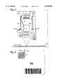
- FIG. 2is a side elevation showing the camera, illuminator and proximity sensor of FIG. 1, partially assembled and cut-away, in proper angular relation to a conveyor belt.
- FIG. 3is a plan view of the components of the machine vision system shown in FIG. 2, as assembled.
- FIG. 4shows a typical glyph with non-glyph clutter on a document.
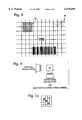
- FIGS. 5-7illustrate the acquisition of images of bands of a document according to the present invention.
- FIG. 8illustrates the partitioning of an image into blocks for subsequent processing.
- FIG. 9illustrates the process of computing one-dimensional projections according to the present invention.
- FIG. 10schematically illustrates an outward search for the boundaries of a glyph.
- FIG. 11illustrates the pixel structure of a symbol forming part of a glyph.
- FIG. 12shows a schematic representation of a sparse kernel for use in the disclosed system.
- FIG. 13illustrates application of the sparse kernel to a glyph image.
- FIG. 14illustrates a search area for finding a maximum correlation response.
- FIG. 15illustrates a search area for refinement of symbol location.
- FIG. 16illustrates a correlation function for discriminating symbols.
- a machine vision system 10is shown in FIG. 1 and includes a camera 12, preferably a high-resolution digital camera with a CCD sensor and a 16-millimeter fixed focal length lens.
- An illuminator or radiation source 14, preferably in the form of a pulsed array of LEDsis used to illuminate a document D or other item to be sensed.
- the pulses of illuminator 14 and the image produced by camera 12are controlled and monitored by a CPU 16.
- a proximity sensor 18is used to signal CPU 16 that the leading edge of a document D has passed beneath proximity sensor 18.
- CPU 16then calculates an appropriate delay before triggering pulses of illumination from illuminator 14. Images from camera 12 are monitored by CPU 16 during appropriate time periods, based on the pulses provided by illuminator 14.
- FIG. 2shows a more detailed representation of the arrangement of the camera and related components of machine vision system 10.
- Camera 12preferably is mounted approximately perpendicular to a conveyor C that carries documents D to be scanned.
- Illuminator 14includes opposed, angled LED canisters 20 mounted on either side of camera 12, preferably at an angle A of approximately 21-degrees to either side of the axis of camera 12, as shown in FIG. 3.
- an array of twenty LEDs emitting approximately 690 nanometer-wavelength lightworks well with the LEDs grouped tightly in a cylindrical canister, and with a diffusing lens mounted between (or as part of) illuminator 14 and document D.
- One of the canistersis shown cutaway to illustrate its internal structure. Other wavelengths of electromagnetic radiation may be used, with appropriate changes of the radiation source and sensor, but the visible light source and sensor of the described illuminator 14 and camera 12 are believed to work well for most document reading.
- the disclosed proximity sensoris light-based, and includes a fiber optic cable 22 that is mounted adjacent conveyor C, aimed approximately perpendicularly to conveyor C. Conveyor C moves at speeds up to 400-inches per second.
- illuminator 14is pulsed to produce a flash of light for approximately 10-microseconds, and approximately 10 separate images are taken by producing 10 separate pulses.
- Brackets 26preferably mount directly to bracket 24, through spot welding or screws, and brackets 24 and 28 mount to a supporting block 30.
- a typical glyph 50is shown in FIG. 4 with associated marks that may be present on the document to be scanned.
- the glyphincludes rows and columns of symbols 60, including upstroke symbols 62 and downstroke symbols 64. Of course, other types of symbols could be used as well.
- the first step in reading the glyphis to acquire or capture an image of the glyph. Acquiring an image of glyph 50 involves capturing a series of images of overlapping bands 52 along a document 54, as illustrated in FIGS. 5-7.
- FIGS. 6 and 7depict schematically the relative positions of the two sets of bands. Each band has a width approximately twice the size of the glyph to insure that the entire glyph is contained in one of the bands. Typically, the bands extend across the width of the document perpendicular to the direction of travel.
- each imageis divided into a series of square blocks 56 of pixels.
- the size of the blockfor instance 32 ⁇ 32, is chosen to be slightly less than one-half of the size of the glyph. This insures that at least one of the blocks will fall entirely within the glyph. See FIG. 8.
- Each blockis processed to determine how much it resembles a glyph. This is accomplished in the disclosed embodiment by calculating vertical and horizontal projections for each block as follows: ##EQU1## See FIG. 9. These projections are then compared to a generally saw-tooth or step-function shaped reference projection or kernel based on the appearance of an average glyph. More specifically, a series of correlations are computed between the reference projection and the vertical projections to locate a maximum correlation for each block. It is necessary to compute a series of correlations because the location of the strokes within the part of a glyph contained in the block is unknown. Therefore, the correlations must be computed over a series of shifted positions or phases spanning a range equivalent to the spacing between strokes to insure that the maximum correlation value is located.
- a suitable reference projectionis:
- the reference functiononly includes 25 elements to allow a complete correlation to be conducted at each of 8 shifted positions in the depicted example. Also, the values used in the reference function are chosen to reflect real world printing and image capture variations. Thus, the boundaries between rows or columns of strokes are not perfectly defined.
- an overall scoreis computed for each block as follows: ##EQU2## where the max -- hor -- cor -- block is the maximum correlation located in the particular block and the max -- hor -- col -- overall is the maximum horizontal correlation found in any block.
- the block with the maximum block -- score in any of the blocks in any of the bandsis taken as the coarse location of the glyph.
- the imageis searched outwardly from the box to locate the boundaries of the glyph, as indicated schematically in FIG. 10.
- the outward search of the disclosed embodimentrelies on the relative contrast between regions of the image containing strokes and regions between strokes. Typically it will be assumed that the brightness W of the paper will be at least twice the brightness of printed pixels B on the page.
- symbols or strokes in the disclosed embodimentare printed as an upwardly or downwardly oriented pattern of three black pixels on a five-by-five cell having a white background.
- the patterns for the two types of symbolshave a region of overlap at the center where there is a black pixel for either stroke type.
- the vertical or horizontal projections through regions containing strokeswill have an average brightness of 0.8W+0.2B, i.e., one in five pixels will be black along any line. Regions between strokes will have an average brightness of W because they contain no black pixels.
- W ⁇ 2 ⁇ Bthe ratio of the average brightness in stroke regions to average brightness between columns or rows of strokes is determined to be ⁇ 0.9.
- the extent of the glyphis determined, it is desirable to more precisely locate the top-left corner of the glyph.
- thisis accomplished by running a correlation with a sparse kernel 70 as illustrated in FIG. 12.
- the kernelis divided into cells 72 corresponding in size to the symbol cell size.
- the spacing between non-zero entries in the kernelmatches the cell size and therefore the interstroke spacing within the glyph. See FIG. 13.
- the non-zero valuesare positioned at the region of intersection of the two symbol types so that, when the correlation kernel is properly aligned, a strong response is generated for both upstrokes and downstrokes.
- the correlation responseis maximized when the kernel is centered with the upper left negative one centered over the top left stroke.
- the negative valuesare multiplied by the low brightness pixel values at the centers of the stroke and the positive values in the kernel are multiplied by the high brightness pixel values in the white space around the glyph.
- correlationsare typically taken over a range of 10-25 pixels horizontally and vertically, as indicated by the box 74 in FIG. 14. It should be understood that it is possible to ignore any entries in the kernel that are equal to zero when computing the correlation value. Use of a plus or minus one in the non-zero entries makes the correlation computation into a simple series of additions. Thus, although the effect of the disclosed system is to utilize a sparse kernel, the actual implementation would simply sum periodically spaced pixels in the image.
- each strokeis processed to determine whether it is an up or a down stroke.
- the processing of strokesis summarized in Table 2.
- the first step in processing a strokeis to further refine the location. This is accomplished in the disclosed embodiment by searching for a minimum pixel over a block 78 of pixels centered at the expected center of the stroke. See FIG. 15. A typical size for this block is 5 ⁇ 5 pixels. This refinement process allows the system to accommodate slight printing variations in the stroke location or size.
- a square block of pixels centered on the strokeis correlated with an X-shaped kernel 80 as shown in FIG. 16.
- the X-shaped kernelincludes negative ones in one diagonal and positive ones in the other diagonal. The entry at the region of intersection of the two diagonals is zero since the brightness of the corresponding pixel is not indicative of whether the stroke is an upstroke or a downstroke. If the stroke is a down stroke, the result of the correlation will be greater than zero because of the additive effect of the brighter white pixels in the other diagonal. If the stroke is an upstroke, on the other hand, the correlation will be negative because of the subtractive effect of the brighter white pixels on the downstroke diagonal.
- a threshold valuecan be incorporated wherein the system reports the stroke as unknown unless the result of the correlation exceeds the threshold.
- the next strokeis located by adding the nominal distance between strokes to the refined position of the current stroke and then refining the location of the new stroke as previously described. This process is repeated for each of the strokes and the resulting pattern of upstrokes and downstrokes is converted to a string of ones and zeros.
- the resultant data stringis used to verify that the document has been printed on the correct stock, for example, or to verify proper association of documents. It should be recognized that the disclosed system can be used to locate and decode multiple glyphs on the same document, some of which may be placed on the document at different stages in the document processing, or be pre-printed on the document in the case of forms.
Landscapes
- Physics & Mathematics (AREA)
- Engineering & Computer Science (AREA)
- Health & Medical Sciences (AREA)
- Electromagnetism (AREA)
- General Health & Medical Sciences (AREA)
- Toxicology (AREA)
- Artificial Intelligence (AREA)
- Computer Vision & Pattern Recognition (AREA)
- General Physics & Mathematics (AREA)
- Theoretical Computer Science (AREA)
- Image Analysis (AREA)
Abstract
Description
ref=[2, 1, -2, -2, -2, -1, 2, 2, 2, 0, -2, -2, -2, 0, 2, 2, 1, -1, -2, -2, -1, 1, 2, 2, 0]
TABLE 1 __________________________________________________________________________// initialize valleys and peaks by finding the valley and // peak in the distance from one stroke to the next previous.sub.-- peak.sub.-- pixel = 0 previous.sub.-- peak.sub.-- value = 0 previous.sub.-- valley.sub.-- pixel=0 previous.sub.-- valley.sub.-- value=0 previous.sub.-- was.sub.-- peak=false pixel = "center pixel of block" stroke.sub.-- distance="distance from one stroke to another stroke" while(pixel <= "center pixel of block" + stroke.sub.-- distance) // traverse one stroke distance { pixel.sub.-- value = h[pixel] if ("pixel.sub.-- value is less than all its neighbors") // at the bottom of a valley { previous.sub.-- valley.sub.-- pixel = pixel previous.sub.-- valley.sub.-- value = pixel.sub.-- value previous was.sub.-- peak=false } else if ("pixel.sub.-- value is greater than all its neighbors") // at the top of a peak { previous.sub.-- peak.sub.-- pixel = pixel previous.sub.-- peak.sub.-- value = pixel.sub.-- value previous.sub.-- was.sub.-- peak = true } pixel++; // move to next pixel } // end while traversing one stroke distance contrast.sub.-- threshold = 0.9 while (pixel < image.sub.-- width) // while extending rightward { pixel.sub.-- value = h[pixel] if (previous.sub.-- was.sub.-- peak) // heading downward { if ("pixel.sub.-- value is less than all its neighbors" and (pixel.sub.-- value/previous.sub.-- peak.sub.-- value)<=contrast.sub.-- threshold) { // at the bottom of a valley previous.sub.-- valley.sub.-- pixel = pixel previous.sub.-- valley.sub.-- value = pixel.sub.-- value previous.sub.-- was.sub.-- peak = false } } else { // heading upward if ("pixel.sub.-- value is greater than all its neighbors" and (previous.sub.-- valley.sub.-- value/pixel.sub.-- value)<=contrast.sub.-- threshold) { // at the top of a peak previous.sub.-- peak.sub.-- pixel = pixel previous.sub.-- peak.sub.-- value = pixel.sub.-- value previous.sub.-- was.sub.-- peak = true } } if (previous.sub.-- was.sub.-- peak) { if ( (pixel - previous.sub.-- peak.sub.-- pixel)>=stroke.sub.-- distance) break // should have encountered a valley by now } else { if (pixel - previous.sub.-- valley.sub.-- pixel) >= stroke.sub.-- distance) break // should have encountered a peak by now } pixel++ // move to next pixel } // end while extending rightward glyph.sub.-- extent.sub.-- right = pixel // record how far the search went on the right __________________________________________________________________________ TABLE 2 ______________________________________ for each row in the glyph for each column in the glyph { <refine the location of the stroke> <read the stroke> <advance to the next stroke> } <advance to the next glyph row> } ______________________________________Claims (21)
Priority Applications (2)
| Application Number | Priority Date | Filing Date | Title |
|---|---|---|---|
| US09/399,638US6078698A (en) | 1999-09-20 | 1999-09-20 | System for reading data glyphs |
| US09/571,062US6298171B1 (en) | 1999-03-23 | 2000-05-15 | System for reading data glyphs |
Applications Claiming Priority (1)
| Application Number | Priority Date | Filing Date | Title |
|---|---|---|---|
| US09/399,638US6078698A (en) | 1999-09-20 | 1999-09-20 | System for reading data glyphs |
Related Child Applications (1)
| Application Number | Title | Priority Date | Filing Date |
|---|---|---|---|
| US09/571,062ContinuationUS6298171B1 (en) | 1999-03-23 | 2000-05-15 | System for reading data glyphs |
Publications (1)
| Publication Number | Publication Date |
|---|---|
| US6078698Atrue US6078698A (en) | 2000-06-20 |
Family
ID=23580339
Family Applications (2)
| Application Number | Title | Priority Date | Filing Date |
|---|---|---|---|
| US09/399,638Expired - LifetimeUS6078698A (en) | 1999-03-23 | 1999-09-20 | System for reading data glyphs |
| US09/571,062Expired - Fee RelatedUS6298171B1 (en) | 1999-03-23 | 2000-05-15 | System for reading data glyphs |
Family Applications After (1)
| Application Number | Title | Priority Date | Filing Date |
|---|---|---|---|
| US09/571,062Expired - Fee RelatedUS6298171B1 (en) | 1999-03-23 | 2000-05-15 | System for reading data glyphs |
Country Status (1)
| Country | Link |
|---|---|
| US (2) | US6078698A (en) |
Cited By (17)
| Publication number | Priority date | Publication date | Assignee | Title |
|---|---|---|---|---|
| US6298171B1 (en)* | 1999-03-23 | 2001-10-02 | Christopher W. Lorton | System for reading data glyphs |
| US20020015536A1 (en)* | 2000-04-24 | 2002-02-07 | Warren Penny G. | Apparatus and method for color image fusion |
| US6669085B1 (en)* | 2002-08-07 | 2003-12-30 | Hewlett-Packard Development Company, L.P. | Making language localization and telecommunications settings in a multi-function device through image scanning |
| US20040107986A1 (en)* | 2002-12-06 | 2004-06-10 | Neilson Andy C. | High throughput microcalorimeter systems and methods |
| US20040197905A1 (en)* | 2003-01-16 | 2004-10-07 | Thermogenic Imagining | Methods and devices for monitoring cellular metabolism in microfluidic cell-retaining chambers |
| US20050054028A1 (en)* | 2003-09-10 | 2005-03-10 | Thermogenic Imaging | Method and device for measuring multiple physiological properties of cells |
| US20060259983A1 (en)* | 2005-05-13 | 2006-11-16 | Xerox Corporation | System and method for controlling reproduction of documents containing sensitive information |
| US20060278724A1 (en)* | 2005-06-08 | 2006-12-14 | Xerox Corporation | System and method for placement and retrieval of embedded information within a document |
| US20070017968A1 (en)* | 2005-07-22 | 2007-01-25 | Xerox Corporation | Method for reconciliation of metered machine bills |
| US20070087401A1 (en)* | 2003-10-17 | 2007-04-19 | Andy Neilson | Analysis of metabolic activity in cells using extracellular flux rate measurements |
| US20080014571A1 (en)* | 2006-07-13 | 2008-01-17 | Seahorse Bioscience | Cell analysis apparatus and method |
| US20100124761A1 (en)* | 2008-10-14 | 2010-05-20 | Neilson Andy C | Method and device for measuring extracellular acidification and oxygen consumption rate with higher precision |
| US20140247359A1 (en)* | 2013-03-04 | 2014-09-04 | Toshiba Tec Kabushiki Kaisha | Scanner apparatus |
| US9494577B2 (en) | 2012-11-13 | 2016-11-15 | Seahorse Biosciences | Apparatus and methods for three-dimensional tissue measurements based on controlled media flow |
| US20170346984A1 (en)* | 2016-05-31 | 2017-11-30 | Toshiba Tec Kabushiki Kaisha | Scanner apparatus |
| US10118177B2 (en) | 2014-06-02 | 2018-11-06 | Seahorse Bioscience | Single column microplate system and carrier for analysis of biological samples |
| US10885338B2 (en) | 2019-05-23 | 2021-01-05 | International Business Machines Corporation | Identifying cable ends using augmented reality |
Families Citing this family (4)
| Publication number | Priority date | Publication date | Assignee | Title |
|---|---|---|---|---|
| US6601772B1 (en)* | 2000-07-14 | 2003-08-05 | Intellidot Corporation | Compact matrix code and one-touch device and method for code reading |
| DE60033535T2 (en)* | 2000-12-15 | 2007-10-25 | Mei, Inc. | Currency validator |
| US8453922B2 (en)* | 2010-02-09 | 2013-06-04 | Xerox Corporation | Method for one-step document categorization and separation using stamped machine recognizable patterns |
| US11392806B2 (en)* | 2020-02-12 | 2022-07-19 | Adobe Inc. | Differentiable rasterizer for vector font generation and editing |
Citations (116)
| Publication number | Priority date | Publication date | Assignee | Title |
|---|---|---|---|---|
| US3260517A (en)* | 1963-11-22 | 1966-07-12 | Bell & Howell Co | Predetermined feed selection for multi-station inserters |
| US3570840A (en)* | 1967-07-14 | 1971-03-16 | Bell & Howell Co | Selective insertion machine having variable capacity insertion station |
| US3588086A (en)* | 1970-03-18 | 1971-06-28 | Bell & Howell Co | Insertion machine having feedback light control system |
| US3606728A (en)* | 1969-09-08 | 1971-09-21 | Bell & Howell Co | Insertion machine |
| US3652828A (en)* | 1969-10-20 | 1972-03-28 | Bell & Howell Co | Selective insertion machine having selective document marking |
| US3949363A (en)* | 1974-06-28 | 1976-04-06 | Recognition Equipment, Incorporated | Bar-Code/MICR/OCR merge |
| US4061900A (en)* | 1976-04-16 | 1977-12-06 | Data General Corporation | Indicia validation system |
| US4251798A (en)* | 1978-05-31 | 1981-02-17 | Symbol Technologies | Portable laser scanning arrangement for and method of evaluating and validating bar code symbols |
| US4369361A (en)* | 1980-03-25 | 1983-01-18 | Symbol Technologies, Inc. | Portable, stand-alone, desk-top laser scanning workstation for intelligent data acquisition terminal and method of scanning |
| US4387297A (en)* | 1980-02-29 | 1983-06-07 | Symbol Technologies, Inc. | Portable laser scanning system and scanning methods |
| US4402088A (en)* | 1981-04-09 | 1983-08-30 | Recognition Equipment Incorporated | OCR And bar code reading using area array |
| US4408344A (en)* | 1981-04-09 | 1983-10-04 | Recognition Equipment Incorporated | OCR and Bar code reader using multi port matrix array |
| US4409470A (en)* | 1982-01-25 | 1983-10-11 | Symbol Technologies, Inc. | Narrow-bodied, single-and twin-windowed portable laser scanning head for reading bar code symbols |
| US4435732A (en)* | 1973-06-04 | 1984-03-06 | Hyatt Gilbert P | Electro-optical illumination control system |
| US4473746A (en)* | 1981-07-30 | 1984-09-25 | Bell & Howell Company | Multiple head optical scanner |
| US4488679A (en)* | 1982-11-01 | 1984-12-18 | Western Publishing Company, Inc. | Code and reading system |
| US4542528A (en)* | 1981-04-09 | 1985-09-17 | Recognition Equipment Incorporated | OCR and bar code reader with optimized sensor |
| US4639873A (en)* | 1984-02-03 | 1987-01-27 | Bell & Howell Company | Insertion machine with postage categorization and selective merchandising |
| US4672457A (en)* | 1970-12-28 | 1987-06-09 | Hyatt Gilbert P | Scanner system |
| US4728195A (en)* | 1986-03-19 | 1988-03-01 | Cognex Corporation | Method for imaging printed circuit board component leads |
| US4743773A (en)* | 1984-08-23 | 1988-05-10 | Nippon Electric Industry Co., Ltd. | Bar code scanner with diffusion filter and plural linear light source arrays |
| US4760248A (en)* | 1985-02-28 | 1988-07-26 | Symbol Technologies, Inc. | Portable laser diode scanning head |
| US4782220A (en)* | 1986-09-29 | 1988-11-01 | Mars, Incorporated | Method and apparatus for bar code data autodiscrimination |
| US4794239A (en)* | 1987-10-13 | 1988-12-27 | Intermec Corporation | Multitrack bar code and associated decoding method |
| US4855581A (en)* | 1988-06-17 | 1989-08-08 | Microscan Systems Incorporated | Decoding of barcodes by preprocessing scan data |
| US4861972A (en)* | 1987-11-05 | 1989-08-29 | Spectra-Physics, Inc. | Bar code scanner and method of programming |
| US4874933A (en)* | 1987-08-21 | 1989-10-17 | Recognition Equipment Incorporated | Ambient illumination bar code reader |
| US4879456A (en)* | 1987-06-18 | 1989-11-07 | Spectra-Physics, Inc. | Method of decoding a binary scan signal |
| US4896026A (en)* | 1988-10-31 | 1990-01-23 | Symbol Technologies, Inc. | Laser diode scanner with improved shock mounting |
| US4972359A (en)* | 1987-04-03 | 1990-11-20 | Cognex Corporation | Digital image processing system |
| US4998010A (en)* | 1988-04-08 | 1991-03-05 | United Parcel Service Of America, Inc. | Polygonal information encoding article, process and system |
| US5013022A (en)* | 1989-08-18 | 1991-05-07 | Quad/Tech, Inc. | Apparatus and method for assembling signatures |
| US5033725A (en)* | 1989-05-25 | 1991-07-23 | Svecia Antiqua Limited | Method of checking and combining separate documents or part documents of the letter and envelope type |
| US5039075A (en)* | 1989-07-12 | 1991-08-13 | R. R. Donnelley & Sons Company | Automatic document gathering and personalization system |
| US5060980A (en)* | 1990-05-30 | 1991-10-29 | Xerox Corporation | Form utilizing encoded indications for form field processing |
| US5067088A (en)* | 1990-02-16 | 1991-11-19 | Johnson & Quin, Inc. | Apparatus and method for assembling mass mail items |
| US5114128A (en)* | 1991-02-27 | 1992-05-19 | U.S. News & World Report, L.P. | Process and apparatus for personalizing magazines, books and other print media |
| US5135160A (en)* | 1990-08-17 | 1992-08-04 | Opticon, Inc. | Portable bar code reader utilizing pulsed LED array |
| US5144118A (en)* | 1990-03-05 | 1992-09-01 | Spectra-Physics, Inc. | Bar code scanning system with multiple decoding microprocessors |
| US5184005A (en)* | 1990-01-08 | 1993-02-02 | Nippondenso Co. Ltd. | Non-decoded type bar code reading apparatus |
| US5191540A (en)* | 1990-09-05 | 1993-03-02 | Pitney Bowes Inc. | Sheets processing apparatus including memory means removably connected thereto |
| US5192856A (en)* | 1990-11-19 | 1993-03-09 | An Con Genetics, Inc. | Auto focusing bar code reader |
| US5196684A (en)* | 1991-03-25 | 1993-03-23 | Opticon, Inc. | Method and apparatus for improving the throughput of a CCD bar code scanner/decoder |
| US5220770A (en)* | 1992-02-27 | 1993-06-22 | R. R. Donnelley & Sons Company | Selective outer envelope inserting system |
| US5237161A (en)* | 1991-06-05 | 1993-08-17 | Psc, Inc. | System for automatically reading symbols, such as bar codes, on objects which are placed in the detection zone of a symbol reading unit, such as a bar code scanner |
| US5239169A (en)* | 1991-05-20 | 1993-08-24 | Microscan Systems Incorporated | Optical signal processor for barcode reader |
| US5245168A (en)* | 1991-06-20 | 1993-09-14 | Nippon Electric Industry Co., Ltd. | Method for controlling bar code reading in bar code reader |
| US5260554A (en)* | 1991-06-05 | 1993-11-09 | Psc, Inc. | System for automatically reading symbols, such as bar codes, on objects which are placed in the detection zone of a symbol reading unit, such as a bar code scanner |
| US5276315A (en)* | 1992-05-14 | 1994-01-04 | United Parcel Service Of America, Inc. | Method and apparatus for processing low resolution images of degraded bar code symbols |
| US5291009A (en)* | 1992-02-27 | 1994-03-01 | Roustaei Alexander R | Optical scanning head |
| US5304786A (en)* | 1990-01-05 | 1994-04-19 | Symbol Technologies, Inc. | High density two-dimensional bar code symbol |
| US5308962A (en)* | 1991-11-01 | 1994-05-03 | Welch Allyn, Inc. | Reduced power scanner for reading indicia |
| US5317654A (en)* | 1991-09-26 | 1994-05-31 | Inscerco Mfg. Inc. | Selective collating and inserting apparatus |
| US5329104A (en)* | 1992-03-10 | 1994-07-12 | Alps Electric Co., Ltd. | Automatically identifying decode apparatus |
| US5349172A (en)* | 1992-02-27 | 1994-09-20 | Alex Roustaei | Optical scanning head |
| US5352879A (en)* | 1992-04-30 | 1994-10-04 | Eastman Kodak Company | DX bar code reader |
| US5354977A (en)* | 1992-02-27 | 1994-10-11 | Alex Roustaei | Optical scanning head |
| US5359185A (en)* | 1992-05-11 | 1994-10-25 | Norand Corporation | Chromatic ranging method and apparatus for reading optically readable information over a substantial range of distances |
| US5367439A (en)* | 1992-12-24 | 1994-11-22 | Cognex Corporation | System for frontal illumination |
| US5377003A (en)* | 1992-03-06 | 1994-12-27 | The United States Of America As Represented By The Department Of Health And Human Services | Spectroscopic imaging device employing imaging quality spectral filters |
| US5383130A (en)* | 1990-06-14 | 1995-01-17 | Moore Business Forms, Inc. | Job separator control |
| US5396260A (en)* | 1992-12-22 | 1995-03-07 | The Center For Innovative Technology | Video instrumentation for the analysis of mineral content in ores and coal |
| US5408084A (en)* | 1993-02-18 | 1995-04-18 | United Parcel Service Of America, Inc. | Method and apparatus for illumination and imaging of a surface using 2-D LED array |
| US5414270A (en)* | 1993-05-14 | 1995-05-09 | R. J. Reynolds Tobacco Company | Method and apparatus for the automatic inspection of cigarette rods for spots and stains |
| US5448049A (en)* | 1994-02-16 | 1995-09-05 | Eastman Kodak Company | Film latent image bar-code (LIBC) reader |
| US5459307A (en)* | 1993-11-30 | 1995-10-17 | Xerox Corporation | System for storage and retrieval of digitally encoded information on a medium |
| US5468946A (en)* | 1994-04-29 | 1995-11-21 | Eastman Kodak Company | Method and apparatus for decoding multi-level bar codes or bi-level bar codes |
| US5481098A (en)* | 1993-11-09 | 1996-01-02 | Spectra-Physics Scanning Systems, Inc. | Method and apparatus for reading multiple bar code formats |
| US5481620A (en)* | 1991-09-27 | 1996-01-02 | E. I. Du Pont De Nemours And Company | Adaptive vision system |
| US5486686A (en)* | 1990-05-30 | 1996-01-23 | Xerox Corporation | Hardcopy lossless data storage and communications for electronic document processing systems |
| US5495537A (en)* | 1994-06-01 | 1996-02-27 | Cognex Corporation | Methods and apparatus for machine vision template matching of images predominantly having generally diagonal and elongate features |
| US5510997A (en)* | 1994-08-30 | 1996-04-23 | Hines; William L. | Dynamic forms and envelopes verification system |
| US5521372A (en)* | 1993-12-22 | 1996-05-28 | Xerox Corporation | Framing codes for robust synchronization and addressing of self-clocking glyph codes |
| US5526050A (en)* | 1994-03-31 | 1996-06-11 | Cognex Corporation | Methods and apparatus for concurrently acquiring video data from multiple video data sources |
| US5528368A (en)* | 1992-03-06 | 1996-06-18 | The United States Of America As Represented By The Department Of Health And Human Services | Spectroscopic imaging device employing imaging quality spectral filters |
| US5536924A (en)* | 1994-06-07 | 1996-07-16 | Intermec Corporation | Method and apparatus for matrix symbology imager |
| US5536928A (en)* | 1990-10-03 | 1996-07-16 | Seagull Scientific Systems, Inc. | System and method for scanning bar codes |
| US5548326A (en)* | 1993-10-06 | 1996-08-20 | Cognex Corporation | Efficient image registration |
| US5576532A (en)* | 1995-01-03 | 1996-11-19 | Xerox Corporation | Interleaved and interlaced sync codes and address codes for self-clocking glyph codes |
| US5583954A (en)* | 1994-03-01 | 1996-12-10 | Cognex Corporation | Methods and apparatus for fast correlation |
| US5593017A (en)* | 1994-03-18 | 1997-01-14 | Environmental Products Corporation | Method and apparatus for identifying information contained in surface deviations |
| US5600121A (en)* | 1995-03-20 | 1997-02-04 | Symbol Technologies, Inc. | Optical reader with independent triggering and graphical user interface |
| US5602937A (en)* | 1994-06-01 | 1997-02-11 | Cognex Corporation | Methods and apparatus for machine vision high accuracy searching |
| US5608639A (en)* | 1995-01-13 | 1997-03-04 | Wallace Computer Services, Inc. | System and method for printing, assembly and verifying a multiple-part printed product |
| US5637854A (en)* | 1995-09-22 | 1997-06-10 | Microscan Systems Incorporated | Optical bar code scanner having object detection |
| US5640199A (en)* | 1993-10-06 | 1997-06-17 | Cognex Corporation | Automated optical inspection apparatus |
| US5657403A (en)* | 1992-06-01 | 1997-08-12 | Cognex Corporation | Vision coprocessing |
| US5655759A (en)* | 1995-09-28 | 1997-08-12 | Xerox Corporation | Apparatus and method of controlling insertion of substrates into a stream of imaged substrates |
| US5659167A (en)* | 1994-04-05 | 1997-08-19 | Metanetics Corporation | Visually interactive decoding of dataforms |
| US5673334A (en)* | 1995-11-30 | 1997-09-30 | Cognex Corporation | Method and apparatus for inspection of characteristics on non-rigid packages |
| US5676302A (en)* | 1995-06-02 | 1997-10-14 | Cognex Corporation | Method and apparatus for crescent boundary thresholding on wire-bonded leads |
| US5697699A (en)* | 1993-09-09 | 1997-12-16 | Asahi Kogaku Kogyo Kabushiki Kaisha | Lighting apparatus |
| US5707055A (en)* | 1996-05-20 | 1998-01-13 | Moore Business Forms, Inc. | Method and system for producing multiple part business forms |
| US5710417A (en)* | 1988-10-21 | 1998-01-20 | Symbol Technologies, Inc. | Bar code reader for reading both one dimensional and two dimensional symbologies with programmable resolution |
| US5717785A (en)* | 1992-01-30 | 1998-02-10 | Cognex Corporation | Method and apparatus for locating patterns in an optical image |
| US5726434A (en)* | 1994-04-01 | 1998-03-10 | Asahi Kogaku Kogyo Kabushiki Kaisha | Encoded symbol reader |
| US5729003A (en)* | 1995-12-27 | 1998-03-17 | Intermec Corporation | Apparatus for preventing formation of condensation on an electrooptical scanner window |
| US5734566A (en)* | 1995-08-25 | 1998-03-31 | Pitney Bowes Inc. | Method and apparatus for keeping a matched document inserter system in synchronization |
| US5739518A (en) | 1995-05-17 | 1998-04-14 | Metanetics Corporation | Autodiscrimination for dataform decoding and standardized recording |
| US5742037A (en) | 1996-03-07 | 1998-04-21 | Cognex Corp. | Method and apparatus for high speed identification of objects having an identifying feature |
| US5742504A (en) | 1995-11-06 | 1998-04-21 | Medar, Inc. | Method and system for quickly developing application software for use in a machine vision system |
| US5744790A (en) | 1996-01-25 | 1998-04-28 | Symbol Technologies, Inc. | Split optics focusing apparatus for CCD-based bar code scanner |
| US5751853A (en) | 1996-01-02 | 1998-05-12 | Cognex Corporation | Locating shapes in two-dimensional space curves |
| US5754670A (en) | 1995-06-21 | 1998-05-19 | Asahi Kogaku Kogyo Kabushiki Kaisha | Data symbol reading system |
| US5754679A (en) | 1995-10-31 | 1998-05-19 | Cognex Corp. | Image rotating method for locating bond pads in an image |
| US5756981A (en) | 1992-02-27 | 1998-05-26 | Symbol Technologies, Inc. | Optical scanner for reading and decoding one- and-two-dimensional symbologies at variable depths of field including memory efficient high speed image processing means and high accuracy image analysis means |
| US5763864A (en) | 1994-07-26 | 1998-06-09 | Meta Holding Corporation | Dataform reader including dual laser and imaging reading assemblies |
| US5768443A (en) | 1995-12-19 | 1998-06-16 | Cognex Corporation | Method for coordinating multiple fields of view in multi-camera |
| US5777314A (en) | 1992-02-27 | 1998-07-07 | Symbol | Optical scanner with fixed focus optics |
| US5777743A (en) | 1994-06-17 | 1998-07-07 | Kensington Laboratories, Inc. | Scribe mark reader |
| US5780831A (en) | 1995-07-12 | 1998-07-14 | Asahi Kogaku Kogyo Kabushiki Kaisha | One-dimensional and two-dimensional data symbol reader |
| US5783811A (en) | 1995-06-26 | 1998-07-21 | Metanetics Corporation | Portable data collection device with LED targeting and illumination assembly |
| US5786582A (en) | 1992-02-27 | 1998-07-28 | Symbol Technologies, Inc. | Optical scanner for reading and decoding one- and two-dimensional symbologies at variable depths of field |
| US5793031A (en) | 1993-03-25 | 1998-08-11 | Asahi Kogaku Kogyo Kabushiki Kaisha | Two-dimensional encoded symbol reading device with plural operating modes |
| US5826271A (en) | 1997-03-14 | 1998-10-27 | Vista Visor Inc | Eyewear in combination with a visor |
| US5862271A (en) | 1996-12-20 | 1999-01-19 | Xerox Corporation | Parallel propagating embedded binary sequences for characterizing and parameterizing two dimensional image domain code patterns in N-dimensional address space |
Family Cites Families (2)
| Publication number | Priority date | Publication date | Assignee | Title |
|---|---|---|---|---|
| US5453611A (en) | 1993-01-01 | 1995-09-26 | Canon Kabushiki Kaisha | Solid-state image pickup device with a plurality of photoelectric conversion elements on a common semiconductor chip |
| US6078698A (en)* | 1999-09-20 | 2000-06-20 | Flir Systems, Inc. | System for reading data glyphs |
- 1999
- 1999-09-20USUS09/399,638patent/US6078698A/ennot_activeExpired - Lifetime
- 2000
- 2000-05-15USUS09/571,062patent/US6298171B1/ennot_activeExpired - Fee Related
Patent Citations (122)
| Publication number | Priority date | Publication date | Assignee | Title |
|---|---|---|---|---|
| US3260517A (en)* | 1963-11-22 | 1966-07-12 | Bell & Howell Co | Predetermined feed selection for multi-station inserters |
| US3570840A (en)* | 1967-07-14 | 1971-03-16 | Bell & Howell Co | Selective insertion machine having variable capacity insertion station |
| US3606728A (en)* | 1969-09-08 | 1971-09-21 | Bell & Howell Co | Insertion machine |
| US3652828A (en)* | 1969-10-20 | 1972-03-28 | Bell & Howell Co | Selective insertion machine having selective document marking |
| US3588086A (en)* | 1970-03-18 | 1971-06-28 | Bell & Howell Co | Insertion machine having feedback light control system |
| US4672457A (en)* | 1970-12-28 | 1987-06-09 | Hyatt Gilbert P | Scanner system |
| US4435732A (en)* | 1973-06-04 | 1984-03-06 | Hyatt Gilbert P | Electro-optical illumination control system |
| US3949363A (en)* | 1974-06-28 | 1976-04-06 | Recognition Equipment, Incorporated | Bar-Code/MICR/OCR merge |
| US4061900A (en)* | 1976-04-16 | 1977-12-06 | Data General Corporation | Indicia validation system |
| US4251798A (en)* | 1978-05-31 | 1981-02-17 | Symbol Technologies | Portable laser scanning arrangement for and method of evaluating and validating bar code symbols |
| US4387297A (en)* | 1980-02-29 | 1983-06-07 | Symbol Technologies, Inc. | Portable laser scanning system and scanning methods |
| US4387297B1 (en)* | 1980-02-29 | 1995-09-12 | Symbol Technologies Inc | Portable laser scanning system and scanning methods |
| US4369361A (en)* | 1980-03-25 | 1983-01-18 | Symbol Technologies, Inc. | Portable, stand-alone, desk-top laser scanning workstation for intelligent data acquisition terminal and method of scanning |
| US4402088A (en)* | 1981-04-09 | 1983-08-30 | Recognition Equipment Incorporated | OCR And bar code reading using area array |
| US4542528A (en)* | 1981-04-09 | 1985-09-17 | Recognition Equipment Incorporated | OCR and bar code reader with optimized sensor |
| US4408344A (en)* | 1981-04-09 | 1983-10-04 | Recognition Equipment Incorporated | OCR and Bar code reader using multi port matrix array |
| US4473746A (en)* | 1981-07-30 | 1984-09-25 | Bell & Howell Company | Multiple head optical scanner |
| US4409470A (en)* | 1982-01-25 | 1983-10-11 | Symbol Technologies, Inc. | Narrow-bodied, single-and twin-windowed portable laser scanning head for reading bar code symbols |
| US4488679A (en)* | 1982-11-01 | 1984-12-18 | Western Publishing Company, Inc. | Code and reading system |
| US4639873A (en)* | 1984-02-03 | 1987-01-27 | Bell & Howell Company | Insertion machine with postage categorization and selective merchandising |
| US4743773A (en)* | 1984-08-23 | 1988-05-10 | Nippon Electric Industry Co., Ltd. | Bar code scanner with diffusion filter and plural linear light source arrays |
| US4760248A (en)* | 1985-02-28 | 1988-07-26 | Symbol Technologies, Inc. | Portable laser diode scanning head |
| US4728195A (en)* | 1986-03-19 | 1988-03-01 | Cognex Corporation | Method for imaging printed circuit board component leads |
| US4782220A (en)* | 1986-09-29 | 1988-11-01 | Mars, Incorporated | Method and apparatus for bar code data autodiscrimination |
| US4972359A (en)* | 1987-04-03 | 1990-11-20 | Cognex Corporation | Digital image processing system |
| US4879456A (en)* | 1987-06-18 | 1989-11-07 | Spectra-Physics, Inc. | Method of decoding a binary scan signal |
| US4874933A (en)* | 1987-08-21 | 1989-10-17 | Recognition Equipment Incorporated | Ambient illumination bar code reader |
| US4794239A (en)* | 1987-10-13 | 1988-12-27 | Intermec Corporation | Multitrack bar code and associated decoding method |
| US4861972A (en)* | 1987-11-05 | 1989-08-29 | Spectra-Physics, Inc. | Bar code scanner and method of programming |
| US4861972B1 (en)* | 1987-11-05 | 2000-12-05 | Spectra Physics Scanning Syst | Bar code scanner and method of programming |
| US4998010A (en)* | 1988-04-08 | 1991-03-05 | United Parcel Service Of America, Inc. | Polygonal information encoding article, process and system |
| US4855581A (en)* | 1988-06-17 | 1989-08-08 | Microscan Systems Incorporated | Decoding of barcodes by preprocessing scan data |
| US5710417A (en)* | 1988-10-21 | 1998-01-20 | Symbol Technologies, Inc. | Bar code reader for reading both one dimensional and two dimensional symbologies with programmable resolution |
| US4896026A (en)* | 1988-10-31 | 1990-01-23 | Symbol Technologies, Inc. | Laser diode scanner with improved shock mounting |
| US5033725A (en)* | 1989-05-25 | 1991-07-23 | Svecia Antiqua Limited | Method of checking and combining separate documents or part documents of the letter and envelope type |
| US5039075A (en)* | 1989-07-12 | 1991-08-13 | R. R. Donnelley & Sons Company | Automatic document gathering and personalization system |
| US5013022A (en)* | 1989-08-18 | 1991-05-07 | Quad/Tech, Inc. | Apparatus and method for assembling signatures |
| US5304786A (en)* | 1990-01-05 | 1994-04-19 | Symbol Technologies, Inc. | High density two-dimensional bar code symbol |
| US5184005A (en)* | 1990-01-08 | 1993-02-02 | Nippondenso Co. Ltd. | Non-decoded type bar code reading apparatus |
| US5067088A (en)* | 1990-02-16 | 1991-11-19 | Johnson & Quin, Inc. | Apparatus and method for assembling mass mail items |
| US5144118A (en)* | 1990-03-05 | 1992-09-01 | Spectra-Physics, Inc. | Bar code scanning system with multiple decoding microprocessors |
| US5486686A (en)* | 1990-05-30 | 1996-01-23 | Xerox Corporation | Hardcopy lossless data storage and communications for electronic document processing systems |
| US5060980A (en)* | 1990-05-30 | 1991-10-29 | Xerox Corporation | Form utilizing encoded indications for form field processing |
| US5383130A (en)* | 1990-06-14 | 1995-01-17 | Moore Business Forms, Inc. | Job separator control |
| US5135160A (en)* | 1990-08-17 | 1992-08-04 | Opticon, Inc. | Portable bar code reader utilizing pulsed LED array |
| US5191540A (en)* | 1990-09-05 | 1993-03-02 | Pitney Bowes Inc. | Sheets processing apparatus including memory means removably connected thereto |
| US5536928A (en)* | 1990-10-03 | 1996-07-16 | Seagull Scientific Systems, Inc. | System and method for scanning bar codes |
| US5192856A (en)* | 1990-11-19 | 1993-03-09 | An Con Genetics, Inc. | Auto focusing bar code reader |
| US5114128A (en)* | 1991-02-27 | 1992-05-19 | U.S. News & World Report, L.P. | Process and apparatus for personalizing magazines, books and other print media |
| US5196684A (en)* | 1991-03-25 | 1993-03-23 | Opticon, Inc. | Method and apparatus for improving the throughput of a CCD bar code scanner/decoder |
| US5239169A (en)* | 1991-05-20 | 1993-08-24 | Microscan Systems Incorporated | Optical signal processor for barcode reader |
| US5237161A (en)* | 1991-06-05 | 1993-08-17 | Psc, Inc. | System for automatically reading symbols, such as bar codes, on objects which are placed in the detection zone of a symbol reading unit, such as a bar code scanner |
| US5260554A (en)* | 1991-06-05 | 1993-11-09 | Psc, Inc. | System for automatically reading symbols, such as bar codes, on objects which are placed in the detection zone of a symbol reading unit, such as a bar code scanner |
| US5245168A (en)* | 1991-06-20 | 1993-09-14 | Nippon Electric Industry Co., Ltd. | Method for controlling bar code reading in bar code reader |
| US5317654A (en)* | 1991-09-26 | 1994-05-31 | Inscerco Mfg. Inc. | Selective collating and inserting apparatus |
| US5608820A (en)* | 1991-09-27 | 1997-03-04 | E. I. Du Pont De Nemours And Company | Parallel processing method and system for identifying valid objects in a background of an image |
| US5481620A (en)* | 1991-09-27 | 1996-01-02 | E. I. Du Pont De Nemours And Company | Adaptive vision system |
| US5734747A (en) | 1991-09-27 | 1998-03-31 | E. I. Du Pont De Nemours And Company | Iterative method and system of identifying valid objects in a background of an image |
| US5308962A (en)* | 1991-11-01 | 1994-05-03 | Welch Allyn, Inc. | Reduced power scanner for reading indicia |
| US5717785A (en)* | 1992-01-30 | 1998-02-10 | Cognex Corporation | Method and apparatus for locating patterns in an optical image |
| US5756981A (en) | 1992-02-27 | 1998-05-26 | Symbol Technologies, Inc. | Optical scanner for reading and decoding one- and-two-dimensional symbologies at variable depths of field including memory efficient high speed image processing means and high accuracy image analysis means |
| US5354977A (en)* | 1992-02-27 | 1994-10-11 | Alex Roustaei | Optical scanning head |
| US5777314A (en) | 1992-02-27 | 1998-07-07 | Symbol | Optical scanner with fixed focus optics |
| US5349172A (en)* | 1992-02-27 | 1994-09-20 | Alex Roustaei | Optical scanning head |
| US5786582A (en) | 1992-02-27 | 1998-07-28 | Symbol Technologies, Inc. | Optical scanner for reading and decoding one- and two-dimensional symbologies at variable depths of field |
| US5291009A (en)* | 1992-02-27 | 1994-03-01 | Roustaei Alexander R | Optical scanning head |
| US5532467A (en)* | 1992-02-27 | 1996-07-02 | Roustaei; Alex | Optical scanning head |
| US5220770A (en)* | 1992-02-27 | 1993-06-22 | R. R. Donnelley & Sons Company | Selective outer envelope inserting system |
| US5377003A (en)* | 1992-03-06 | 1994-12-27 | The United States Of America As Represented By The Department Of Health And Human Services | Spectroscopic imaging device employing imaging quality spectral filters |
| US5528368A (en)* | 1992-03-06 | 1996-06-18 | The United States Of America As Represented By The Department Of Health And Human Services | Spectroscopic imaging device employing imaging quality spectral filters |
| US5329104A (en)* | 1992-03-10 | 1994-07-12 | Alps Electric Co., Ltd. | Automatically identifying decode apparatus |
| US5352879A (en)* | 1992-04-30 | 1994-10-04 | Eastman Kodak Company | DX bar code reader |
| US5359185A (en)* | 1992-05-11 | 1994-10-25 | Norand Corporation | Chromatic ranging method and apparatus for reading optically readable information over a substantial range of distances |
| US5276315A (en)* | 1992-05-14 | 1994-01-04 | United Parcel Service Of America, Inc. | Method and apparatus for processing low resolution images of degraded bar code symbols |
| US5657403A (en)* | 1992-06-01 | 1997-08-12 | Cognex Corporation | Vision coprocessing |
| US5396260A (en)* | 1992-12-22 | 1995-03-07 | The Center For Innovative Technology | Video instrumentation for the analysis of mineral content in ores and coal |
| US5367439A (en)* | 1992-12-24 | 1994-11-22 | Cognex Corporation | System for frontal illumination |
| US5408084A (en)* | 1993-02-18 | 1995-04-18 | United Parcel Service Of America, Inc. | Method and apparatus for illumination and imaging of a surface using 2-D LED array |
| US5793031A (en) | 1993-03-25 | 1998-08-11 | Asahi Kogaku Kogyo Kabushiki Kaisha | Two-dimensional encoded symbol reading device with plural operating modes |
| US5414270A (en)* | 1993-05-14 | 1995-05-09 | R. J. Reynolds Tobacco Company | Method and apparatus for the automatic inspection of cigarette rods for spots and stains |
| US5697699A (en)* | 1993-09-09 | 1997-12-16 | Asahi Kogaku Kogyo Kabushiki Kaisha | Lighting apparatus |
| US5548326A (en)* | 1993-10-06 | 1996-08-20 | Cognex Corporation | Efficient image registration |
| US5640199A (en)* | 1993-10-06 | 1997-06-17 | Cognex Corporation | Automated optical inspection apparatus |
| US5481098A (en)* | 1993-11-09 | 1996-01-02 | Spectra-Physics Scanning Systems, Inc. | Method and apparatus for reading multiple bar code formats |
| US5459307A (en)* | 1993-11-30 | 1995-10-17 | Xerox Corporation | System for storage and retrieval of digitally encoded information on a medium |
| US5521372A (en)* | 1993-12-22 | 1996-05-28 | Xerox Corporation | Framing codes for robust synchronization and addressing of self-clocking glyph codes |
| US5448049A (en)* | 1994-02-16 | 1995-09-05 | Eastman Kodak Company | Film latent image bar-code (LIBC) reader |
| US5583954A (en)* | 1994-03-01 | 1996-12-10 | Cognex Corporation | Methods and apparatus for fast correlation |
| US5593017A (en)* | 1994-03-18 | 1997-01-14 | Environmental Products Corporation | Method and apparatus for identifying information contained in surface deviations |
| US5526050A (en)* | 1994-03-31 | 1996-06-11 | Cognex Corporation | Methods and apparatus for concurrently acquiring video data from multiple video data sources |
| US5726434A (en)* | 1994-04-01 | 1998-03-10 | Asahi Kogaku Kogyo Kabushiki Kaisha | Encoded symbol reader |
| US5659167A (en)* | 1994-04-05 | 1997-08-19 | Metanetics Corporation | Visually interactive decoding of dataforms |
| US5468946A (en)* | 1994-04-29 | 1995-11-21 | Eastman Kodak Company | Method and apparatus for decoding multi-level bar codes or bi-level bar codes |
| US5495537A (en)* | 1994-06-01 | 1996-02-27 | Cognex Corporation | Methods and apparatus for machine vision template matching of images predominantly having generally diagonal and elongate features |
| US5602937A (en)* | 1994-06-01 | 1997-02-11 | Cognex Corporation | Methods and apparatus for machine vision high accuracy searching |
| US5536924A (en)* | 1994-06-07 | 1996-07-16 | Intermec Corporation | Method and apparatus for matrix symbology imager |
| US5777743A (en) | 1994-06-17 | 1998-07-07 | Kensington Laboratories, Inc. | Scribe mark reader |
| US5763864A (en) | 1994-07-26 | 1998-06-09 | Meta Holding Corporation | Dataform reader including dual laser and imaging reading assemblies |
| US5510997A (en)* | 1994-08-30 | 1996-04-23 | Hines; William L. | Dynamic forms and envelopes verification system |
| US5576532A (en)* | 1995-01-03 | 1996-11-19 | Xerox Corporation | Interleaved and interlaced sync codes and address codes for self-clocking glyph codes |
| US5608639A (en)* | 1995-01-13 | 1997-03-04 | Wallace Computer Services, Inc. | System and method for printing, assembly and verifying a multiple-part printed product |
| US5600121A (en)* | 1995-03-20 | 1997-02-04 | Symbol Technologies, Inc. | Optical reader with independent triggering and graphical user interface |
| US5801371A (en) | 1995-03-20 | 1998-09-01 | Symbol Technologies, Inc. | Optical reader with independent triggering and graphical user interface |
| US5739518A (en) | 1995-05-17 | 1998-04-14 | Metanetics Corporation | Autodiscrimination for dataform decoding and standardized recording |
| US5676302A (en)* | 1995-06-02 | 1997-10-14 | Cognex Corporation | Method and apparatus for crescent boundary thresholding on wire-bonded leads |
| US5754670A (en) | 1995-06-21 | 1998-05-19 | Asahi Kogaku Kogyo Kabushiki Kaisha | Data symbol reading system |
| US5783811A (en) | 1995-06-26 | 1998-07-21 | Metanetics Corporation | Portable data collection device with LED targeting and illumination assembly |
| US5780831A (en) | 1995-07-12 | 1998-07-14 | Asahi Kogaku Kogyo Kabushiki Kaisha | One-dimensional and two-dimensional data symbol reader |
| US5734566A (en)* | 1995-08-25 | 1998-03-31 | Pitney Bowes Inc. | Method and apparatus for keeping a matched document inserter system in synchronization |
| US5637854A (en)* | 1995-09-22 | 1997-06-10 | Microscan Systems Incorporated | Optical bar code scanner having object detection |
| US5655759A (en)* | 1995-09-28 | 1997-08-12 | Xerox Corporation | Apparatus and method of controlling insertion of substrates into a stream of imaged substrates |
| US5754679A (en) | 1995-10-31 | 1998-05-19 | Cognex Corp. | Image rotating method for locating bond pads in an image |
| US5742504A (en) | 1995-11-06 | 1998-04-21 | Medar, Inc. | Method and system for quickly developing application software for use in a machine vision system |
| US5673334A (en)* | 1995-11-30 | 1997-09-30 | Cognex Corporation | Method and apparatus for inspection of characteristics on non-rigid packages |
| US5768443A (en) | 1995-12-19 | 1998-06-16 | Cognex Corporation | Method for coordinating multiple fields of view in multi-camera |
| US5729003A (en)* | 1995-12-27 | 1998-03-17 | Intermec Corporation | Apparatus for preventing formation of condensation on an electrooptical scanner window |
| US5751853A (en) | 1996-01-02 | 1998-05-12 | Cognex Corporation | Locating shapes in two-dimensional space curves |
| US5744790A (en) | 1996-01-25 | 1998-04-28 | Symbol Technologies, Inc. | Split optics focusing apparatus for CCD-based bar code scanner |
| US5742037A (en) | 1996-03-07 | 1998-04-21 | Cognex Corp. | Method and apparatus for high speed identification of objects having an identifying feature |
| US5707055A (en)* | 1996-05-20 | 1998-01-13 | Moore Business Forms, Inc. | Method and system for producing multiple part business forms |
| US5862271A (en) | 1996-12-20 | 1999-01-19 | Xerox Corporation | Parallel propagating embedded binary sequences for characterizing and parameterizing two dimensional image domain code patterns in N-dimensional address space |
| US5826271A (en) | 1997-03-14 | 1998-10-27 | Vista Visor Inc | Eyewear in combination with a visor |
Cited By (32)
| Publication number | Priority date | Publication date | Assignee | Title |
|---|---|---|---|---|
| US6298171B1 (en)* | 1999-03-23 | 2001-10-02 | Christopher W. Lorton | System for reading data glyphs |
| US20020015536A1 (en)* | 2000-04-24 | 2002-02-07 | Warren Penny G. | Apparatus and method for color image fusion |
| US6669085B1 (en)* | 2002-08-07 | 2003-12-30 | Hewlett-Packard Development Company, L.P. | Making language localization and telecommunications settings in a multi-function device through image scanning |
| US20040107986A1 (en)* | 2002-12-06 | 2004-06-10 | Neilson Andy C. | High throughput microcalorimeter systems and methods |
| US20040197905A1 (en)* | 2003-01-16 | 2004-10-07 | Thermogenic Imagining | Methods and devices for monitoring cellular metabolism in microfluidic cell-retaining chambers |
| US7638321B2 (en) | 2003-09-10 | 2009-12-29 | Seahorse Bioscience, Inc. | Method and device for measuring multiple physiological properties of cells |
| US20100105578A1 (en)* | 2003-09-10 | 2010-04-29 | Seahorse Bioscience | Method and device for measuring multiple physiological properties of cells |
| US7851201B2 (en) | 2003-09-10 | 2010-12-14 | Seahorse Bioscience, Inc. | Method and device for measuring multiple physiological properties of cells |
| US9170253B2 (en) | 2003-09-10 | 2015-10-27 | Seahorse Bioscience | Method and device for measuring multiple physiological properties of cells |
| US8697431B2 (en) | 2003-09-10 | 2014-04-15 | Seahorse Bioscience, Inc. | Method and device for measuring multiple physiological properties of cells |
| US7276351B2 (en) | 2003-09-10 | 2007-10-02 | Seahorse Bioscience | Method and device for measuring multiple physiological properties of cells |
| US20070238165A1 (en)* | 2003-09-10 | 2007-10-11 | Seahorse Bioscience | Method and device for measuring multiple physiological properties of cells |
| US20100227385A1 (en)* | 2003-09-10 | 2010-09-09 | Seahorse Bioscience | Method and device for measuring multiple physiological properties of cells |
| US20050054028A1 (en)* | 2003-09-10 | 2005-03-10 | Thermogenic Imaging | Method and device for measuring multiple physiological properties of cells |
| US20070087401A1 (en)* | 2003-10-17 | 2007-04-19 | Andy Neilson | Analysis of metabolic activity in cells using extracellular flux rate measurements |
| US20060259983A1 (en)* | 2005-05-13 | 2006-11-16 | Xerox Corporation | System and method for controlling reproduction of documents containing sensitive information |
| US8181261B2 (en) | 2005-05-13 | 2012-05-15 | Xerox Corporation | System and method for controlling reproduction of documents containing sensitive information |
| US7481374B2 (en) | 2005-06-08 | 2009-01-27 | Xerox Corporation | System and method for placement and retrieval of embedded information within a document |
| US20060278724A1 (en)* | 2005-06-08 | 2006-12-14 | Xerox Corporation | System and method for placement and retrieval of embedded information within a document |
| US20070017968A1 (en)* | 2005-07-22 | 2007-01-25 | Xerox Corporation | Method for reconciliation of metered machine bills |
| US8658349B2 (en) | 2006-07-13 | 2014-02-25 | Seahorse Bioscience | Cell analysis apparatus and method |
| US20080014571A1 (en)* | 2006-07-13 | 2008-01-17 | Seahorse Bioscience | Cell analysis apparatus and method |
| US9170255B2 (en) | 2006-07-13 | 2015-10-27 | Seahorse Bioscience | Cell analysis apparatus and method |
| US10359418B2 (en) | 2006-07-13 | 2019-07-23 | Seahorse Bioscience | Cell analysis apparatus and method |
| US8202702B2 (en) | 2008-10-14 | 2012-06-19 | Seahorse Bioscience | Method and device for measuring extracellular acidification and oxygen consumption rate with higher precision |
| US20100124761A1 (en)* | 2008-10-14 | 2010-05-20 | Neilson Andy C | Method and device for measuring extracellular acidification and oxygen consumption rate with higher precision |
| US9494577B2 (en) | 2012-11-13 | 2016-11-15 | Seahorse Biosciences | Apparatus and methods for three-dimensional tissue measurements based on controlled media flow |
| US20140247359A1 (en)* | 2013-03-04 | 2014-09-04 | Toshiba Tec Kabushiki Kaisha | Scanner apparatus |
| US10118177B2 (en) | 2014-06-02 | 2018-11-06 | Seahorse Bioscience | Single column microplate system and carrier for analysis of biological samples |
| US20170346984A1 (en)* | 2016-05-31 | 2017-11-30 | Toshiba Tec Kabushiki Kaisha | Scanner apparatus |
| US10885338B2 (en) | 2019-05-23 | 2021-01-05 | International Business Machines Corporation | Identifying cable ends using augmented reality |
| US11900673B2 (en) | 2019-05-23 | 2024-02-13 | International Business Machines Corporation | Identifying cable ends using augmented reality |
Also Published As
| Publication number | Publication date |
|---|---|
| US6298171B1 (en) | 2001-10-02 |
Similar Documents
| Publication | Publication Date | Title |
|---|---|---|
| US6078698A (en) | System for reading data glyphs | |
| EP0669593B1 (en) | Two-dimensional code recognition method | |
| US7421126B2 (en) | Method and system for searching form features for form identification | |
| US6250551B1 (en) | Autodiscrimination and line drawing techniques for code readers | |
| US7949187B2 (en) | Character string recognition method and device | |
| US6366696B1 (en) | Visual bar code recognition method | |
| EP1086439B1 (en) | Techniques for reading postal codes | |
| US5642442A (en) | Method for locating the position and orientation of a fiduciary mark | |
| US7181066B1 (en) | Method for locating bar codes and symbols in an image | |
| EP0978087B1 (en) | System and method for ocr assisted bar code decoding | |
| US7337970B2 (en) | Barcode scanner decoding | |
| US6708884B1 (en) | Method and apparatus for rapid and precision detection of omnidirectional postnet barcode location | |
| CN103679164A (en) | A method and a system for identifying and processing a mark based on a mobile terminal | |
| JP2009266190A (en) | Symbol information reading apparatus and symbol information reading method | |
| US9571684B1 (en) | Method of using a fiducial in determining two media types of different lengths used on a flatbed scanner | |
| CN1052322C (en) | Mark positioning image processing method and package sorting method | |
| US7726572B2 (en) | Bar code scanning decoding | |
| JP2008250754A (en) | Character string recognition method and device | |
| Rodrigues et al. | Cursive character recognition–a character segmentation method using projection profile-based technique | |
| Kumano et al. | Development of a container identification mark recognition system | |
| Garris et al. | Generalized form registration using structure-based techniques | |
| JPS6325391B2 (en) | ||
| Kitamoto et al. | Digital bleaching and content extraction for the digital archive of rare books | |
| JP2001229339A (en) | Barcode reader | |
| Sawaki et al. | Text-line extraction and character recognition of Japanese newspaper headlines with graphical designs |
Legal Events
| Date | Code | Title | Description |
|---|---|---|---|
| AS | Assignment | Owner name:FLIR SYSTEMS, INC., OREGON Free format text:ASSIGNMENT OF ASSIGNORS INTEREST;ASSIGNOR:WILLIAMS, RICHARD P.;REEL/FRAME:010440/0961 Effective date:19991112 Owner name:FLIR SYSTEMS, INC., OREGON Free format text:ASSIGNMENT OF ASSIGNORS INTEREST;ASSIGNOR:GRINER, JAMES C.;REEL/FRAME:010440/0970 Effective date:19991112 Owner name:FLIR SYSTEMS, INC., OREGON Free format text:ASSIGNMENT OF ASSIGNORS INTEREST;ASSIGNOR:RYSTROM, LARRY;REEL/FRAME:010440/0981 Effective date:19991110 Owner name:FLIR SYSTEMS, INC., OREGON Free format text:ASSIGNMENT OF ASSIGNORS INTEREST;ASSIGNOR:LORTON, CHRISTOPHER W.;REEL/FRAME:010443/0503 Effective date:19991112 | |
| AS | Assignment | Owner name:FLIR SYSTEMS, INC., OREGON Free format text:ASSIGNMENT OF ASSIGNORS INTEREST;ASSIGNOR:ORRELL, JAMES D. III;REEL/FRAME:010446/0094 Effective date:19991110 | |
| AS | Assignment | Owner name:FLIR SYSTEMS, INC., OREGON Free format text:ASSIGNMENT OF ASSIGNORS INTEREST;ASSIGNOR:JONES, CREED F., III;REEL/FRAME:010629/0089 Effective date:19991213 | |
| STCF | Information on status: patent grant | Free format text:PATENTED CASE | |
| FPAY | Fee payment | Year of fee payment:4 | |
| FEPP | Fee payment procedure | Free format text:PAYOR NUMBER ASSIGNED (ORIGINAL EVENT CODE: ASPN); ENTITY STATUS OF PATENT OWNER: LARGE ENTITY | |
| AS | Assignment | Owner name:BANK OF AMERICA, N.A., AS ADMINISTRATIVE AGENT,WAS Free format text:NOTICE OF GRANT OF SECURITY INTEREST;ASSIGNOR:FLIR SYSTEMS, INC.;REEL/FRAME:018420/0494 Effective date:20061006 Owner name:BANK OF AMERICA, N.A., AS ADMINISTRATIVE AGENT, WA Free format text:NOTICE OF GRANT OF SECURITY INTEREST;ASSIGNOR:FLIR SYSTEMS, INC.;REEL/FRAME:018420/0494 Effective date:20061006 | |
| REMI | Maintenance fee reminder mailed | ||
| FPAY | Fee payment | Year of fee payment:8 | |
| SULP | Surcharge for late payment | Year of fee payment:7 | |
| AS | Assignment | Owner name:FLIR SYSTEMS, INC., OREGON Free format text:TERMINATION OF SECURITY INTEREST IN PATENTS RECORDED AT REEL/FRAME 18420/494;ASSIGNOR:BANK OF AMERICA, N.A., AS ADMINISTRATIVE AGENT;REEL/FRAME:025775/0972 Effective date:20110208 | |
| FPAY | Fee payment | Year of fee payment:12 |