US6078475A - Low friction pivot for rotary actuator in disk drive - Google Patents
Low friction pivot for rotary actuator in disk driveDownload PDFInfo
- Publication number
- US6078475A US6078475AUS08/946,723US94672397AUS6078475AUS 6078475 AUS6078475 AUS 6078475AUS 94672397 AUS94672397 AUS 94672397AUS 6078475 AUS6078475 AUS 6078475A
- Authority
- US
- United States
- Prior art keywords
- pivot bearing
- pivot
- bearing socket
- axis
- rotary actuator
- Prior art date
- Legal status (The legal status is an assumption and is not a legal conclusion. Google has not performed a legal analysis and makes no representation as to the accuracy of the status listed.)
- Expired - Lifetime
Links
- 238000013500data storageMethods0.000claimsabstractdescription14
- 230000033001locomotionEffects0.000description8
- 238000010586diagramMethods0.000description5
- 230000036316preloadEffects0.000description4
- 239000000463materialSubstances0.000description3
- 229910000838Al alloyInorganic materials0.000description2
- 239000000853adhesiveSubstances0.000description2
- 230000001070adhesive effectEffects0.000description2
- 230000000712assemblyEffects0.000description2
- 238000000429assemblyMethods0.000description2
- 230000035939shockEffects0.000description2
- HBMJWWWQQXIZIP-UHFFFAOYSA-Nsilicon carbideChemical compound[Si+]#[C-]HBMJWWWQQXIZIP-UHFFFAOYSA-N0.000description2
- 229910010271silicon carbideInorganic materials0.000description2
- 229910000639Spring steelInorganic materials0.000description1
- 238000013016dampingMethods0.000description1
- 230000003247decreasing effectEffects0.000description1
- 238000006073displacement reactionMethods0.000description1
- 239000011521glassSubstances0.000description1
- 239000004519greaseSubstances0.000description1
- 238000010438heat treatmentMethods0.000description1
- 238000010943off-gassingMethods0.000description1
- 239000007787solidSubstances0.000description1
- 239000010935stainless steelSubstances0.000description1
- 229910001220stainless steelInorganic materials0.000description1
- 230000003068static effectEffects0.000description1
- 239000000758substrateSubstances0.000description1
- 239000010409thin filmSubstances0.000description1
Images


Classifications
- F—MECHANICAL ENGINEERING; LIGHTING; HEATING; WEAPONS; BLASTING
- F16—ENGINEERING ELEMENTS AND UNITS; GENERAL MEASURES FOR PRODUCING AND MAINTAINING EFFECTIVE FUNCTIONING OF MACHINES OR INSTALLATIONS; THERMAL INSULATION IN GENERAL
- F16C—SHAFTS; FLEXIBLE SHAFTS; ELEMENTS OR CRANKSHAFT MECHANISMS; ROTARY BODIES OTHER THAN GEARING ELEMENTS; BEARINGS
- F16C17/00—Sliding-contact bearings for exclusively rotary movement
- F16C17/04—Sliding-contact bearings for exclusively rotary movement for axial load only
- F16C17/08—Sliding-contact bearings for exclusively rotary movement for axial load only for supporting the end face of a shaft or other member, e.g. footstep bearings
- G—PHYSICS
- G11—INFORMATION STORAGE
- G11B—INFORMATION STORAGE BASED ON RELATIVE MOVEMENT BETWEEN RECORD CARRIER AND TRANSDUCER
- G11B5/00—Recording by magnetisation or demagnetisation of a record carrier; Reproducing by magnetic means; Record carriers therefor
- G11B5/48—Disposition or mounting of heads or head supports relative to record carriers ; arrangements of heads, e.g. for scanning the record carrier to increase the relative speed
- G11B5/4806—Disposition or mounting of heads or head supports relative to record carriers ; arrangements of heads, e.g. for scanning the record carrier to increase the relative speed specially adapted for disk drive assemblies, e.g. assembly prior to operation, hard or flexible disk drives
- G11B5/4813—Mounting or aligning of arm assemblies, e.g. actuator arm supported by bearings, multiple arm assemblies, arm stacks or multiple heads on single arm
- F—MECHANICAL ENGINEERING; LIGHTING; HEATING; WEAPONS; BLASTING
- F16—ENGINEERING ELEMENTS AND UNITS; GENERAL MEASURES FOR PRODUCING AND MAINTAINING EFFECTIVE FUNCTIONING OF MACHINES OR INSTALLATIONS; THERMAL INSULATION IN GENERAL
- F16C—SHAFTS; FLEXIBLE SHAFTS; ELEMENTS OR CRANKSHAFT MECHANISMS; ROTARY BODIES OTHER THAN GEARING ELEMENTS; BEARINGS
- F16C2370/00—Apparatus relating to physics, e.g. instruments
- F16C2370/12—Hard disk drives or the like
Definitions
- the present inventionrelates to disk drives in general, and in particular to a rotary actuator within disk drives. Still more particularly, the present invention relates to a low friction pivot for a rotary actuator within disk drives.
- a rotary voice coil actuator within a disk drivetypically employs an upper and a lower ball-bearing assemblies. Such assemblies manifest a frictional torque in accordance with the ball friction multiplied by a radius extending from the center of rotation of an actuator shaft to approximately the center of rotation of a nominal rotating ball of the bearing assembly.
- This type of rotary actuator designis relatively low cost and has experienced widespread usages.
- the size of the actuator within these disk drivesalso needs to be smaller and smaller.
- the ratio of friction (both static and dynamic) to actuator inertiamay increase to a point that it becomes very difficult for an actuator-head-positioning servo system to make small displacements that are required for single-track seeking and for following a data-storage track centerline.
- a rotary actuator within a disk driveincludes a transducer head connected to an E-block, a base, and a rotating data-storage disk journalled to the base.
- the rotary actuatorincludes a top plate having a first pivot bearing socket, a bottom plate having a second pivot bearing socket, and a pivot shaft.
- the first pivot bearing socketis placed oppositely facing the second pivot bearing socket defining an axis therebetween.
- the pivot shaftis mounted between the first pivot bearing socket and the second pivot bearing socket along the defined axis, wherein the pivot shaft is embedded within a pivot center of the E-block having an axis of rotation for incrementally rotationally positioning the transducer head at data locations defined on a surface of the rotating data-storage disk.
- the axis of rotation of the E-blockbeing generally coaxial to the defined axis of both bearing sockets.
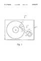
- FIG. 1is a diagram of a disk drive in which a preferred embodiment of the present invention may be incorporated;
- FIG. 2is a cross-sectional diagram of an actuator pivot assembly in accordance with a preferred embodiment of the present invention
- FIG. 3is a detailed illustration of a first pivot bearing socket within the actuator pivot assembly of FIG. 2, in accordance with a preferred embodiment of the present invention.
- FIG. 4is a detailed illustration of a second pivot bearing socket within the actuator pivot assembly of FIG. 2, in accordance with a preferred embodiment of the present invention.
- the present inventionmay be implemented in any direct access storage device. As will be understood by those skilled in the art, the present invention is applicable for disk drives having a rotary actuator.
- Disk drive 10includes a suitable formed aluminum-alloy base 11, a rotating data-storage disk 14 mounted to a spindle 13 conventionally containing an in-hub spindle motor (not shown), and a rotary actuator assembly 12.
- Actuator assembly 12includes a flat voice coil 15 that moves within a high intensity magnetic gap formed by a fixed permanent magnet assembly (not shown) such that current applied in one direction of voice coil 15 causes clockwise movement of actuator assembly 12, and current applied in a reverse direction causes counter-clockwise movement thereof.
- Voice coil 15is a part of a solid body block 16 within actuator assembly 12.
- Body block 16is also referred to as an E-block.
- a head arm 17extends from E-block 16 and supports a load beam 19 that preloads a transducer head 18 towards the storage surface of data-storage disk 14.
- a minute read/write headis located conventionally at one slider rail of transducer head 18 facing the storage surface of data-storage disk 14.
- Data-storage disk 14may be made of, for example, very flat aluminum alloy, or glass substrate, sputter coated with a suitable thin film magnetic storage media.
- transducer head 18"flies" on an air bearing formed at the surface of data-storage disk 14.
- actuator pivot assembly 20The pivoting of actuator assembly 12 with respect to base 11 is provided for by an actuator pivot assembly 20.
- FIG. 2there is illustrated a cross-sectional diagram of actuator pivot assembly 20, in accordance with a preferred embodiment of the present invention.
- Actuator pivot assembly 20includes a pivot shaft 21, a top plate 24, and a bottom plate 28.
- Pivot shaft 21is embedded within the pivot center of E-block 16 of actuator assembly 12.
- E-block 16As shown in FIG. 2, it is apparent that E-block 16 earned its name from the fact that its comb portion resembles the capital letter "E.”
- Top plate 24 and bottom plate 28are formed as a single integral sub-unit of E-block 16.
- pivot shaft 21has an upper end and a lower end. Each of these ends is generally conical in shape and has a spherical tip. Furthermore, top plate 24 provides a pivot bearing socket 23. Pivot bearing socket 23 is also conical in shape with a spherical tip. The size of pivot bearing socket 23 is slighter larger than the diameter of the upper end of pivot shaft 21, thereby forming a seat for the upper end of pivot shaft 21. Similarly, pivot bottom socket 27 is also conical in shape with a spherical tip. The size of pivot bearing socket 27 is slighter larger than the diameter of the lower end of pivot shaft 21, thereby also forming a seat for the lower end of pivot shaft 21. Pivot bearing socket 23 and pivot bearing socket 27 are substantially identical in size and shape. Bottom plate 28 is preferably formed as an integral part of base 11 for improved rigidity and alignment accuracy, but may optionally be formed as a discrete unit and subsequently attached to base 11.
- pivot bearing socket 23within actuator pivot assembly 20, in accordance with a preferred embodiment of the present invention.
- pivot bearing socket 23is attached to top plate 24 of actuator pivot assembly 20 for providing a seat for the upper end of pivot shaft 21.
- Pivot bearing socket 23may be captivated within top plate 24 by either friction or adhesives.
- Both pivot bearing socket 23 and pivot shaft 21are made of compatible materials that have low wear, low friction and adequate strength for fragility issues.
- pivot bearing socket 23is made of silicon carbide and pivot shaft 21 is made of 17-7 stainless steel with a hardened tip.
- pivot bearing socket 23is generally conical with a spherical tip and the size of pivot bearing socket 23 is slighter larger than the tip radius of the upper end of pivot shaft 21, which is also conical in shape.
- the tip radius of the upper end of pivot shaft 21is sized such that a locus line extending from a center point of the tip to a center of rotation of pivot shaft 21 forms a desired angle with a main axis of rotation of actuator assembly 12. This particular angle will determine axial stiffness versus lateral stiffness of actuator assembly 12.
- actuator pivot assembly 20has an axial preload that is greater than the shock-limit g load.
- Top plate 24is designed with a compliance to provide the necessary axial preload. Thin area 32 in top plate 24 that allows compliance along the vertical axis can be accomplished with the proper material with heat treatment or a spring steel insert around pivot bearing socket 23.
- the radius of the spherical tip at the upper end of pivot shaft 21is approximately 0.005 inches.
- the corresponding pivot bearing socket 23has a slightly larger radius of 0.005005 inches. Both of these radii for both tip and socket are carefully selected to limit contact stress during a worst case shock impact of 125 g's (along the vertical axis). The required axial preload, coefficient of friction, and the radii of tip/socket define the friction torque; and the resultant friction torque is lower than that of the prior art ball bearing designs.
- pivot bearing socket 27within actuator pivot assembly 20, in accordance with a preferred embodiment of the present invention.
- pivot bearing socket 27is attached to bottom plate 28 of actuator pivot assembly 20 for providing a seat for the lower end of pivot shaft 21.
- Pivot bearing socket 27may be captivated within bottom plate 28 by either friction or adhesives.
- Pivot bearing socket 27is made of materials compatible with pivot shaft 21, which is low wear, low friction, and strong enough for fragility issues.
- pivot bearing socket 27is made of silicon carbide.
- pivot bearing socket 27is generally conical with a spherical tip and the size of pivot bearing socket 27 is slighter larger than the tip radius of the lower end of pivot shaft 21, which is also conical in shape.
- the tip radius of the lower end of pivot shaft 21is sized such that a locus line extending from a center point of the tip to a center of rotation of pivot shaft 21 forms a desired angle with a main axis of rotation of actuator assembly 12. This particular angle will also determine axial stiffness versus lateral stiffness of actuator assembly 12.
- the radius of the spherical tip at the lower end of pivot shaft 21is approximately 0.005 inches.
- the corresponding pivot bearing socket 27has a slightly larger radius of 0.005005 inches. Similar to the upper end of pivot shaft 21 described previously, both of these radii are carefully selected to limit contact stress during a worst case shock impact of 125 g's along the vertical axis.
- the present inventionprovides an improved rotary actuator to be utilized within a disk drive.
- This improved rotary actuatorhas a reduced friction pivot. With this reduced friction pivot, the rotary actuator will have less hysteresis and the associated servo system that controls the actuator movements will be more apt to cope with future disk drives having even higher track densities.
- Another advantage of eliminating the ball bearing assembly design under the prior artis that potential outgassing of the grease is eliminated.
Landscapes
- Engineering & Computer Science (AREA)
- General Engineering & Computer Science (AREA)
- Mechanical Engineering (AREA)
- Moving Of Heads (AREA)
Abstract
Description
Claims (4)
Priority Applications (1)
| Application Number | Priority Date | Filing Date | Title |
|---|---|---|---|
| US08/946,723US6078475A (en) | 1997-10-08 | 1997-10-08 | Low friction pivot for rotary actuator in disk drive |
Applications Claiming Priority (1)
| Application Number | Priority Date | Filing Date | Title |
|---|---|---|---|
| US08/946,723US6078475A (en) | 1997-10-08 | 1997-10-08 | Low friction pivot for rotary actuator in disk drive |
Publications (1)
| Publication Number | Publication Date |
|---|---|
| US6078475Atrue US6078475A (en) | 2000-06-20 |
Family
ID=25484890
Family Applications (1)
| Application Number | Title | Priority Date | Filing Date |
|---|---|---|---|
| US08/946,723Expired - LifetimeUS6078475A (en) | 1997-10-08 | 1997-10-08 | Low friction pivot for rotary actuator in disk drive |
Country Status (1)
| Country | Link |
|---|---|
| US (1) | US6078475A (en) |
Cited By (13)
| Publication number | Priority date | Publication date | Assignee | Title |
|---|---|---|---|---|
| US6411471B1 (en)* | 1999-06-30 | 2002-06-25 | Seagate Technology Llc | Low friction bearing pivot for disc drive |
| US20030043717A1 (en)* | 2001-09-04 | 2003-03-06 | Abrahamson Scott D. | Method for aligning actuator assembly to a base in a miniature optical disk drive |
| US6560856B1 (en)* | 2000-06-26 | 2003-05-13 | International Business Machines Corporation | Self-aligning fixture for pre-loading and aligning pivot bearing assemblies |
| US6631053B1 (en)* | 1999-09-28 | 2003-10-07 | Maxtor Corporation | Actuator pivot assembly that pivotally connects an actuator to a base of a disk drive |
| US20040130827A1 (en)* | 2001-11-30 | 2004-07-08 | Western Digital Technologies, Inc. | Pivot bearing cartridge including central pivot element and ball bearing set |
| US20040165308A1 (en)* | 2003-02-19 | 2004-08-26 | Gunderson Neal F. | Internal support member in a hermetically sealed data storage device |
| US20040184703A1 (en)* | 2002-08-26 | 2004-09-23 | Bakir Muhannad S. | Dual-mode/function optical and electrical interconnects, methods of fabrication thereof, and methods of use thereof |
| WO2004074879A3 (en)* | 2003-02-19 | 2005-04-14 | Seagate Technology Llc | Internal support member in a hermetically sealed data storage device |
| EP1594124A2 (en) | 2004-05-07 | 2005-11-09 | Samsung Electronics Co., Ltd. | Pivot shaft fixing structure in data storage device |
| US20060119988A1 (en)* | 2004-01-22 | 2006-06-08 | David Tsang | Head stack assembly incorporating a pivot assembly having solid lubrication |
| US20070032833A1 (en)* | 2005-08-05 | 2007-02-08 | Seagate Technology Llc | Electrical Feedthrough assembly with elastic ring interface |
| US10180829B2 (en)* | 2015-12-15 | 2019-01-15 | Nxp Usa, Inc. | System and method for modulo addressing vectorization with invariant code motion |
| US20190348072A1 (en)* | 2017-01-25 | 2019-11-14 | Galleon International Corporation | Bearing systems |
Citations (10)
| Publication number | Priority date | Publication date | Assignee | Title |
|---|---|---|---|---|
| US3770906A (en)* | 1971-03-11 | 1973-11-06 | Ricoh Kk | Flutter resisting magnetic recording and reproducing apparatus |
| US4151573A (en)* | 1977-06-13 | 1979-04-24 | Tandon Magnetics Corp. | Magnetic recording device for double sided media |
| US4197566A (en)* | 1977-12-21 | 1980-04-08 | Mitsubishi Denki Kabushiki Kaisha | Floating head slider holding apparatus and its use |
| US4340918A (en)* | 1979-02-08 | 1982-07-20 | Grundig E.M.V. Elektro-Mechanische Versuchsanstalt Max Grundig | Pivoted magnetic head mount with adjustable limit |
| US4628386A (en)* | 1982-02-26 | 1986-12-09 | Lcc.Cice-Compagnie Europeenne De Composants Electroniques | Magnetic reading and/or writing head support assembly |
| US4764830A (en)* | 1985-11-09 | 1988-08-16 | Alps Electric Co., Ltd. | Magnetic head assembly in floppy disk drive |
| US4905107A (en)* | 1988-02-05 | 1990-02-27 | Klein Enrique J | Torsion transducer for magnetic storage disk drives |
| US5510940A (en)* | 1992-11-23 | 1996-04-23 | Quantum Corporation | Ball spindle for reduced friction rotary actuator in disk drive |
| US5555211A (en)* | 1995-01-23 | 1996-09-10 | Quantum Corporation | Improved spindle shaft for attaching a cover in a disk drive |
| US5835309A (en)* | 1995-05-22 | 1998-11-10 | International Business Machines Corporation | Pivot bearing |
- 1997
- 1997-10-08USUS08/946,723patent/US6078475A/ennot_activeExpired - Lifetime
Patent Citations (10)
| Publication number | Priority date | Publication date | Assignee | Title |
|---|---|---|---|---|
| US3770906A (en)* | 1971-03-11 | 1973-11-06 | Ricoh Kk | Flutter resisting magnetic recording and reproducing apparatus |
| US4151573A (en)* | 1977-06-13 | 1979-04-24 | Tandon Magnetics Corp. | Magnetic recording device for double sided media |
| US4197566A (en)* | 1977-12-21 | 1980-04-08 | Mitsubishi Denki Kabushiki Kaisha | Floating head slider holding apparatus and its use |
| US4340918A (en)* | 1979-02-08 | 1982-07-20 | Grundig E.M.V. Elektro-Mechanische Versuchsanstalt Max Grundig | Pivoted magnetic head mount with adjustable limit |
| US4628386A (en)* | 1982-02-26 | 1986-12-09 | Lcc.Cice-Compagnie Europeenne De Composants Electroniques | Magnetic reading and/or writing head support assembly |
| US4764830A (en)* | 1985-11-09 | 1988-08-16 | Alps Electric Co., Ltd. | Magnetic head assembly in floppy disk drive |
| US4905107A (en)* | 1988-02-05 | 1990-02-27 | Klein Enrique J | Torsion transducer for magnetic storage disk drives |
| US5510940A (en)* | 1992-11-23 | 1996-04-23 | Quantum Corporation | Ball spindle for reduced friction rotary actuator in disk drive |
| US5555211A (en)* | 1995-01-23 | 1996-09-10 | Quantum Corporation | Improved spindle shaft for attaching a cover in a disk drive |
| US5835309A (en)* | 1995-05-22 | 1998-11-10 | International Business Machines Corporation | Pivot bearing |
Non-Patent Citations (2)
| Title |
|---|
| Floppy Disk Device, JA 0236158, Nov. 22, 1985 (Abstract).* |
| T.A. Hickox, Head Mount, IBM Technical Disclosure Bulletin, vol. 18, No. 2, Jul. 1975, p. 541.* |
Cited By (21)
| Publication number | Priority date | Publication date | Assignee | Title |
|---|---|---|---|---|
| US6411471B1 (en)* | 1999-06-30 | 2002-06-25 | Seagate Technology Llc | Low friction bearing pivot for disc drive |
| US6631053B1 (en)* | 1999-09-28 | 2003-10-07 | Maxtor Corporation | Actuator pivot assembly that pivotally connects an actuator to a base of a disk drive |
| US6560856B1 (en)* | 2000-06-26 | 2003-05-13 | International Business Machines Corporation | Self-aligning fixture for pre-loading and aligning pivot bearing assemblies |
| US6651340B2 (en)* | 2000-06-26 | 2003-11-25 | International Business Machines Corporation | Self-aligning fixture for pre-loading and aligning pivot bearing assemblies |
| US6826138B2 (en)* | 2001-09-04 | 2004-11-30 | Dphi Acquisitions, Inc. | Method for aligning actuator assembly to a base in a miniature optical disk drive |
| US20030043717A1 (en)* | 2001-09-04 | 2003-03-06 | Abrahamson Scott D. | Method for aligning actuator assembly to a base in a miniature optical disk drive |
| US6856491B1 (en) | 2001-11-30 | 2005-02-15 | Western Digital Technologies, Inc. | Pivot bearing cartridge including central pivot element and ball bearing set |
| US6856492B2 (en) | 2001-11-30 | 2005-02-15 | Western Digital Technologies, Inc. | Pivot bearing cartridge including central pivot element and ball bearing set |
| US20040130827A1 (en)* | 2001-11-30 | 2004-07-08 | Western Digital Technologies, Inc. | Pivot bearing cartridge including central pivot element and ball bearing set |
| US20040184703A1 (en)* | 2002-08-26 | 2004-09-23 | Bakir Muhannad S. | Dual-mode/function optical and electrical interconnects, methods of fabrication thereof, and methods of use thereof |
| US20040165308A1 (en)* | 2003-02-19 | 2004-08-26 | Gunderson Neal F. | Internal support member in a hermetically sealed data storage device |
| WO2004074879A3 (en)* | 2003-02-19 | 2005-04-14 | Seagate Technology Llc | Internal support member in a hermetically sealed data storage device |
| US6930858B2 (en)* | 2003-02-19 | 2005-08-16 | Seagate Technology Llc | Internal support member in a hermetically sealed data storage device |
| US20060119988A1 (en)* | 2004-01-22 | 2006-06-08 | David Tsang | Head stack assembly incorporating a pivot assembly having solid lubrication |
| EP1594124A2 (en) | 2004-05-07 | 2005-11-09 | Samsung Electronics Co., Ltd. | Pivot shaft fixing structure in data storage device |
| EP1594124A3 (en)* | 2004-05-07 | 2009-05-13 | Samsung Electronics Co., Ltd. | Pivot shaft fixing structure in data storage device |
| US20070032833A1 (en)* | 2005-08-05 | 2007-02-08 | Seagate Technology Llc | Electrical Feedthrough assembly with elastic ring interface |
| US7599147B2 (en) | 2005-08-05 | 2009-10-06 | Seagate Technology Llc | Electrical feedthrough assembly with elastic ring interface |
| US10180829B2 (en)* | 2015-12-15 | 2019-01-15 | Nxp Usa, Inc. | System and method for modulo addressing vectorization with invariant code motion |
| US20190348072A1 (en)* | 2017-01-25 | 2019-11-14 | Galleon International Corporation | Bearing systems |
| US10978099B2 (en)* | 2017-01-25 | 2021-04-13 | Galleon International Corporation | Bearing systems |
Similar Documents
| Publication | Publication Date | Title |
|---|---|---|
| US5510940A (en) | Ball spindle for reduced friction rotary actuator in disk drive | |
| US5161077A (en) | Actuator arm with a steel sleeve for thermal off track compensation | |
| US5521778A (en) | Disk drive with primary and secondary actuator drives | |
| KR100372994B1 (en) | Magnetic disc unit having load and unload mechanism | |
| US6751064B2 (en) | Head supporting device and disk drive using the same | |
| US6078475A (en) | Low friction pivot for rotary actuator in disk drive | |
| JPH0982052A (en) | Head actuator mechanism of disk recording / reproducing apparatus | |
| US6043956A (en) | Suspension for disk drive | |
| EP0613121A1 (en) | Rotating magnetic storage device | |
| US6920019B2 (en) | Device and method for improved stiction reliability in disk drives employing padded sliders | |
| US6417994B1 (en) | Swage plate with protruded walls to increase retention torque in hard disk applications | |
| US5757588A (en) | Hard disk assembly having a pivot bearing assembly comprising fingers bearing on a shaft | |
| JP2002237160A (en) | Head support device | |
| US20060114611A1 (en) | Slider having features for reduced slider-media impact | |
| US10460753B1 (en) | Helium drive pivot design to reduce cover screw tension induced torque and stiffness changes | |
| US6865061B2 (en) | Disk drive | |
| US6618226B2 (en) | Locally deformable sleeve on disk drive pivot assembly | |
| US6113277A (en) | Actuator pivot bearing with reduced hysteresis | |
| JP2001155448A (en) | Magnetic disk drive | |
| US6522501B1 (en) | Magnetic recording medium and magnetic write/read apparatus using the same | |
| KR200296381Y1 (en) | Gram load controlling device improvement read/write in hard disk drive | |
| JPH08221912A (en) | Head actuator for magnetic disk drive | |
| JPS62167683A (en) | Floating head mechanism | |
| JPH0760579B2 (en) | Negative pressure type floating head load mechanism | |
| JPH11339410A (en) | Magnetic disk drive with load / unload mechanism |
Legal Events
| Date | Code | Title | Description |
|---|---|---|---|
| AS | Assignment | Owner name:INTERNATIONAL BUSINESS MACHINES CORPORATION, CALIF Free format text:ASSIGNMENT OF ASSIGNORS INTEREST;ASSIGNOR:LAWSON, DREW BRENT;REEL/FRAME:008965/0087 Effective date:19971006 | |
| STCF | Information on status: patent grant | Free format text:PATENTED CASE | |
| CC | Certificate of correction | ||
| FEPP | Fee payment procedure | Free format text:PAYOR NUMBER ASSIGNED (ORIGINAL EVENT CODE: ASPN); ENTITY STATUS OF PATENT OWNER: LARGE ENTITY | |
| AS | Assignment | Owner name:MARIANA HDD B.V., NETHERLANDS Free format text:ASSIGNMENT OF ASSIGNORS INTEREST;ASSIGNOR:INTERNATIONAL BUSINESS MACHINES CORPORATION;REEL/FRAME:013663/0348 Effective date:20021231 | |
| AS | Assignment | Owner name:HITACHI GLOBAL STORAGE TECHNOLOGIES NETHERLANDS B. Free format text:CHANGE OF NAME;ASSIGNOR:MARIANA HDD B.V.;REEL/FRAME:013746/0146 Effective date:20021231 | |
| FPAY | Fee payment | Year of fee payment:4 | |
| FEPP | Fee payment procedure | Free format text:PAYER NUMBER DE-ASSIGNED (ORIGINAL EVENT CODE: RMPN); ENTITY STATUS OF PATENT OWNER: LARGE ENTITY Free format text:PAYOR NUMBER ASSIGNED (ORIGINAL EVENT CODE: ASPN); ENTITY STATUS OF PATENT OWNER: LARGE ENTITY | |
| FPAY | Fee payment | Year of fee payment:8 | |
| FPAY | Fee payment | Year of fee payment:12 | |
| AS | Assignment | Owner name:HGST, NETHERLANDS B.V., NETHERLANDS Free format text:CHANGE OF NAME;ASSIGNOR:HGST, NETHERLANDS B.V.;REEL/FRAME:029341/0777 Effective date:20120723 Owner name:HGST NETHERLANDS B.V., NETHERLANDS Free format text:CHANGE OF NAME;ASSIGNOR:HITACHI GLOBAL STORAGE TECHNOLOGIES NETHERLANDS B.V.;REEL/FRAME:029341/0777 Effective date:20120723 | |
| AS | Assignment | Owner name:WESTERN DIGITAL TECHNOLOGIES, INC., CALIFORNIA Free format text:ASSIGNMENT OF ASSIGNORS INTEREST;ASSIGNOR:HGST NETHERLANDS B.V.;REEL/FRAME:040818/0551 Effective date:20160831 |