US6078269A - Battery-powered, RF-interconnected detector sensor system - Google Patents
Battery-powered, RF-interconnected detector sensor systemDownload PDFInfo
- Publication number
- US6078269A US6078269AUS08/967,760US96776097AUS6078269AUS 6078269 AUS6078269 AUS 6078269AUS 96776097 AUS96776097 AUS 96776097AUS 6078269 AUS6078269 AUS 6078269A
- Authority
- US
- United States
- Prior art keywords
- detector
- alarm
- detectors
- indicative
- receiver
- Prior art date
- Legal status (The legal status is an assumption and is not a legal conclusion. Google has not performed a legal analysis and makes no representation as to the accuracy of the status listed.)
- Expired - Lifetime
Links
Images


Classifications
- G—PHYSICS
- G08—SIGNALLING
- G08B—SIGNALLING OR CALLING SYSTEMS; ORDER TELEGRAPHS; ALARM SYSTEMS
- G08B25/00—Alarm systems in which the location of the alarm condition is signalled to a central station, e.g. fire or police telegraphic systems
- G08B25/009—Signalling of the alarm condition to a substation whose identity is signalled to a central station, e.g. relaying alarm signals in order to extend communication range
- G—PHYSICS
- G08—SIGNALLING
- G08B—SIGNALLING OR CALLING SYSTEMS; ORDER TELEGRAPHS; ALARM SYSTEMS
- G08B17/00—Fire alarms; Alarms responsive to explosion
- G08B17/10—Actuation by presence of smoke or gases, e.g. automatic alarm devices for analysing flowing fluid materials by the use of optical means
- G08B17/11—Actuation by presence of smoke or gases, e.g. automatic alarm devices for analysing flowing fluid materials by the use of optical means using an ionisation chamber for detecting smoke or gas
- G—PHYSICS
- G08—SIGNALLING
- G08B—SIGNALLING OR CALLING SYSTEMS; ORDER TELEGRAPHS; ALARM SYSTEMS
- G08B19/00—Alarms responsive to two or more different undesired or abnormal conditions, e.g. burglary and fire, abnormal temperature and abnormal rate of flow
- G08B19/005—Alarms responsive to two or more different undesired or abnormal conditions, e.g. burglary and fire, abnormal temperature and abnormal rate of flow combined burglary and fire alarm systems
- G—PHYSICS
- G08—SIGNALLING
- G08B—SIGNALLING OR CALLING SYSTEMS; ORDER TELEGRAPHS; ALARM SYSTEMS
- G08B25/00—Alarm systems in which the location of the alarm condition is signalled to a central station, e.g. fire or police telegraphic systems
- G08B25/001—Alarm cancelling procedures or alarm forwarding decisions, e.g. based on absence of alarm confirmation
- G—PHYSICS
- G08—SIGNALLING
- G08B—SIGNALLING OR CALLING SYSTEMS; ORDER TELEGRAPHS; ALARM SYSTEMS
- G08B25/00—Alarm systems in which the location of the alarm condition is signalled to a central station, e.g. fire or police telegraphic systems
- G08B25/003—Address allocation methods and details
- G—PHYSICS
- G08—SIGNALLING
- G08B—SIGNALLING OR CALLING SYSTEMS; ORDER TELEGRAPHS; ALARM SYSTEMS
- G08B25/00—Alarm systems in which the location of the alarm condition is signalled to a central station, e.g. fire or police telegraphic systems
- G08B25/01—Alarm systems in which the location of the alarm condition is signalled to a central station, e.g. fire or police telegraphic systems characterised by the transmission medium
- G08B25/10—Alarm systems in which the location of the alarm condition is signalled to a central station, e.g. fire or police telegraphic systems characterised by the transmission medium using wireless transmission systems
Definitions
- the present inventionrelates to detection systems in general, and more particularly, to a CSMA-type network of battery-powered, RF-interconnected, wireless sensors for detecting and alerting to emergency conditions such as smoke, fire, gas, intrusion, and the like.
- Detection systemswhich include a plurality of sensor units detecting and alerting to conditions such as smoke, fire, gas, motion, etc. are numerous and well known in the art.
- Some systemssuch as those described in U.S. Pat. No. 5,587,705 for MULTIPLE ALERT SMOKE DETECTORS to Morris et al and U.S. Pat. No. 5,386,209 for CLUSTER ALARM MONITORING SYSTEM to Thomas disclose the use of different audible signals in a detector system to alert personnel of a condition as well as using RF signals to communicate with other detectors in the network.
- these systemslike many other similar systems, often require A.C. powered base stations or A.C. coupled detectors to facilitate network operation. This is disadvantageous in that it results in increased costs and network complexity such as running cables, providing connected base stations, maintaining large AC power sources, etc.
- Another detector system described in U.S. Pat. No. 4,734,680 for DETECTION SYSTEM WITH RANDOMIZED TRANSMISSION to Gehman et al.discloses an integrated network of different sensors for communicating different conditions to an A.C. powered base unit or supervisory unit by means of randomized RF transmissions in order to avoid clashing between multiple units when sending to the supervising unit. While Gehman discloses a randomizing scheme for signal transmission, the Whyman et al. invention is directed toward transmission times between battery-operated sensor units and continuously active, A.C. powered base units, which are very short (on the order of milliseconds).
- a transmission loopmight occur, for example, if a sensor detects an initial puff of smoke (prior to commencement of larger, consistent puffs) and a signal is initiated in response thereto to a second or more units. If the sensor during a brief interval between puffs no longer detects the smoke, it might send an all-clear signal back to the next units. The second or next unit would send the signals (alarm or all-clear) back to the first, which would send it back again and so forth until the batteries run down.
- a network of battery-powered sensorsoperable without the need of a base station to effectively communicate over a wireless RF communication scheme the occurrence of an emergency condition so that personnel located remotely from the alarm condition may be notified. It is also desirable that the detector system be operable with a number of different types of sensing devices to indicate various alarm or emergency conditions and include an associated priority scheme for prioritizing various conditions to most effectively alert the users to such conditions.
- the controllerincludes prioritization means for determining the relative priority of the received RF signals and stimuli indicative of a particular condition to enable the appropriate mode of operation; and timer means responsive to the detector operating mode for enabling the transmitter to transmit RF messages immediately after the receiver no longer detects incoming message activity.
- the receiveris sensed at a randomized time interval to reduce the probability of multiple simultaneous transmissions.
- FIG. 1is an exemplary diagram depicting a detector system of the present invention.
- FIG. 2is an exemplary detailed diagram of a detector of the present invention.
- FIG. 2Ais a description of the modes of each detector.
- FIG. 2Bis an exemplary circuit and timing diagram of the operation of the latched mode.
- FIG. 3is an exemplary circuit diagram of the controller chip and associated circuitry.
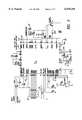
- FIG. 4is an exemplary diagram of the transmission delay circuitry.
- FIG. 4Ais an illustration depicting the structure of a transmitted RF message.
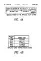
- FIG. 4Bis an illustration depicting the message type bit pattern for each RF transmitted message.
- FIG. 5is an exemplary diagram of the transmitter encoding circuitry.
- FIG. 6is an exemplary diagram of the receiver decoding circuitry.
- FIG. 7is an exemplary diagram depicting the data checking circuitry.
- FIG. 7Ais an exemplary diagram depicting an RF network of detectors and peripheral devices.
- FIG. 8is an exemplary diagram depicting the timing of the receiver activation and decoding.
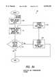
- FIG. 8Ais an exemplary diagram illustrating the detector unit prioritization scheme of the present invention.
- FIG. 8Bis an exemplary diagram illustrating a detector having multiple sensor types connected to a single detector unit ASIC.
- FIG. 9is an exemplary diagram depicting an integrated network of different detector types.
- a detection system 10 of the present inventionFor exemplary purposes, a four detector/sensor system is shown and its operation described. However, any number of two or more detectors may comprise the system, which is not limited to detectors of the same type (e.g. smoke detectors). Rather, the system may be an "integrated" system comprising battery-operated multiple detector types, including smoke, fire (i.e. flame), heat, gas, photoelectric, carbon monoxide, motion, and intrusion detectors interconnected through a wireless local area network (LAN) of radio frequency signals.
- LANwireless local area network
- the system of the present inventionincludes a plurality of detectors.
- Each detector 20, 20A-Cincludes a local sensor 25, local alarm 30, controlling means 35, RF transmitter 40, and RF receiver 45.
- Each detectorfurther includes a battery 50 for powering the detector, identification means 55, timer means 36, latch means 37, and prioritization means 38 within controlling means 35, reset means 60 for resetting the individual detector as well as the entire system, and test means 65 for initiating a system test, all enclosed within a protective housing 70.
- Each detector 20,20A-Cis operable in a variety of modes, with each mode corresponding to a particular condition.
- a number of mutually exclusive modes of operationare defined for detector 20 in the present invention, and include: Standby; Alarm; Low Battery; Reset; Test; AUX2; AUX3; and Wait mode.
- a mode entered as a result of a stimulus occurring at the location of the particular detectoris called a local mode, whereas a mode driven by receipt of an RF message transmitted from another detector unit is a remote mode.
- the Standby mode of operationis entered when battery power from 9 Volt DC battery 50 is applied to detector 20.
- Detector 20will remain in Standby mode until an external stimulus (e.g. smoke) is applied or the depletion of battery power causes a transition to another mode of operation.
- the local sensor 25 of the first detector 20senses an alarm condition such as smoke within the range of its sensor and causes an electrical signal to be applied to controller means 35.
- the controller means 35includes a custom application specific integrated circuit (ASIC) chip for controlling all of the timing and messaging occurring throughout the detector 20.
- the reset meansis a push button switch for initiating a reset command signal to the controller.
- the test meansis also a push button activated switch for generating a test command signal to the controller. In Standby mode, controller means 35 periodically senses its input line connected to sensor 25 to determine if an alarm condition has occurred.
- controller meansIn Standby mode, controller means also periodically activates its receiver to determine if any signal data transmitted from another detector is present for reception and decoding. In response to the electrical signal from sensor 25 indicative of a smoke or "alarm" condition, controller means 35 causes the detector 20 to enter Local Alarm mode and activate the alarm 30, thereby sounding a horn alarm at the location of the detector. Concurrently, the controlling means also activates light emitting means 51 such as an LED at the "local” detector 20 with a flashing pattern indicative of the alarm condition. The controller then activates the transmitter to immediately transmit an amplitude modulated (AM) RF message to the other detector units (so-called “remote” units) in the system that an alarm condition has occurred.
- AMamplitude modulated
- the controller at the "local” detectori.e. detector which initially sensed the "alarm” condition
- the local detector 20remains “latched” in local “alarm” mode with its LED and horn active until either the "reset” push button 60 is depressed on the local detector 20, or a "remote reset” message is received over the RF link from a remote detector unit. This "latching” prevents the detector from resetting even after the sensor 25 no longer detects the presence of a local phenomena such as smoke, but rather requires a manual or remote reset signal in order to indicate and transmit an "all clear” signal.
- While “local” detector 20is transmitting the "alarm” message, remote detector units 20A, 20B, and 20C are powered up and in Standby mode, awaiting either receipt of an external message from another (i.e. remote) detector or a local stimulus from which to respond. If remote detector 20A is in operating range of "local” detector 20's RF transmission, then, upon the periodic receiver activation at detector 20A, receipt of the "alarm" message at receiver 45A causes "remote" detector 20A to enter a "Remote Alarm” mode. In Remote Alarm mode, controller means 35A activates alarm 30A, thereby sounding a horn alarm at the location of the detector 20A. Controller means 35A also causes receiver 45A to be sensed at a regular interval.
- the transmitter 40AWhen the receiver is sensed and no further message activity is detected by the receiver, the transmitter 40A is then enabled and the "alarm" message signal transmitted by detector 20 is retransmitted by detector 20A so that any detector units located beyond the range of the original transmission, but within the range of the retransmitting unit 20A, may be activated. In this manner, an area of coverage much larger than a single unit to unit range is achieved.
- transmitter 40AUpon completion of transmission by detector 20A, transmitter 40A is disabled and receiver 45A is reactivated and periodically sampled to permit reception of any messages from any of the other detector units.
- Detector 20Aremains in remote “alarm” mode with its horn active until either the "reset” push button 60A is depressed, sensor 25A detects an alarm condition local to detector 20A, or a "remote reset” message is received over the RF link from a remote detector unit. If an alarm condition local to detector 20A is determined, the controlling means also activates an LED at detector 20A with a flashing pattern indicative of the alarm condition. Thus a flashing LED pattern may be used to indicate the origin of the alarm condition. Moreover, the absence of a flashing LED pattern on a particular detector whose horn is sounding discloses both the alarm condition and that this detector is relaying the alarm condition rather than initiating it.
- remote detector units 20B and 20Ctransition from Standby mode to Remote Alarm mode by the reception of RF signals from either the local detector unit 20 or another remote detector.
- detector 20Bmay be out of range of detector 20 but within range of remote detector 20A.
- detector 20Btransitions to remote alarm mode upon reception of the retransmitted alarm message signal from detector 20A.
- Detector 20Bthen subsequently retransmits the RF signal received from detector 20A for further alarm propagation, while concurrently activating its alarm horn.
- Detector 20Cmay be within range of detector 20B, but out of range of all other detectors. Consequently, detector 20D is activated into Remote Alarm mode by receipt of detector 20C's alarm message retransmission.
- the overlapping coverage areas of each of the detector unitspermit broad area coverage and enhance the effectiveness of the overall detection warning system.
- Smoke detector 20according to the preferred embodiment is shown in FIG. 1 and operable in each of the modes identified in FIG. 2A.
- controlling means 35is operable to control the smoke detector to transition to a particular mode of operation.
- the controller meansincludes the customized ASIC chip 40 and associated circuitry shown in FIG. 3, which enables control of both timing requirements for AM RF transmission and reception as well as mode transition and operation. While AM RF transmission is preferable because of its low cost relative to FM transmission schemes and adequate fidelity for the present purposes, frequency modulated schemes including FM OOK and PSK may also be used to transmit, receive and decode the data messages.
- Each of the detector units comprising the detector system of FIG. 1share a common radio channel for signal transmission and reception.
- CSMACarrier Sense Multiple Access
- each detectoremploys a holdoff timer 36 shown in FIG. 2 to stagger each unit's sensing of its receiver and, thus, transmission times, to permit effective network communication.
- message activityis sensed by testing the output of the receiver for data each time the holdoff timer expires. It is thus desirable for each detector unit to have a different value in its holdoff timer at any given point in time in order to reduce the probability that multiple units will sense a lack of activity simultaneously, thus avoiding multiple simultaneous transmissions.
- Each unit's holdoff timeris initialized when power is applied to the unit.
- the holdoff timermay be implemented using conventional circuit devices such as a six-bit ripple counter to provide a uniform random number generator.
- the ripple counter 40comprises logic modules U16-U48.
- Logic module 50encompassing gates U1 and U2 decodes the all zeros state to produce a two pulse per second signal 50A. This signal is high on the rising edge of a count signal 60A only one time in three because of the divide by three circuit implemented in U9-U11 of module 60. This produces a Start signal 70B for activating the transmitter up to six (6) seconds after the signal Data Present 70A input to module 70 goes false (i.e. low) indicating no message activity, for at least two pulses from module A.
- the signal Data Presentis the signal sampled at the receiver output.
- the probability that the holdoff timers in any two units are synchronizedis simply 1/64, or about 0.016.
- each detectorfurther has associated with it identification means comprising a five position dip switch 45 as shown in FIG. 3.
- identification meanscomprising a five position dip switch 45 as shown in FIG. 3.
- system identification numbersare available to differentiate among different detection systems which may be operating in close proximity to one another (e.g. a neighbor's alarm system) to prevent RF signal interference and crosstalk among systems.
- the system of detectors according to the present inventionis capable of transmitting RF messages consisting of 16 bit data words at a bit rate of 1024 Hz. Each data word is divided into three subfields, comprising 1) message type; 2) system identification number; and 3) a fixed pattern shown in FIG. 4A. The first eight bits of the data word indicate message type.
- Each of the data wordsis stored in memory via conventional means such as EPROM, ROM or other electronic memory means capable of quick retrieval, and also provides flexibility for additional message types for future enhancements.
- FIG. 4Billustrates the bit patterns for each of these message types.
- the next five bits of the data wordindicate the system identification number described above.
- the last three bitsconsist of a fixed pattern (110).
- Each transmitted messageconsists of a single word transmitted continuously for a period of twenty-four (24) seconds. Because the detection system of the present invention is wireless and operates on battery power, relatively long transmission sequences are necessary to enable the receiver and decode the data.
- the transmitterincludes conventional circuitry for encoding the six message type functions into eight bit patterns having a low probability of cross detection (i.e. cross correlation).
- FIG. 5shows an exemplary circuit diagram for encoding each of the message types into eight bit patterns.
- Modules 50, 60, 70, 80, and 90each have an enable input G2 indicative of each particular message type (50A-90A) and multiple inputs coupled to either ground or Vcc potential.
- Eight bit parallel output lines from each moduleare coupled together at line 95 for data transmission.
- the input data bit codes 0-4 for module 100represent the buffered dip switch 45 inputs from FIG. 3.
- a load enable signal 100A from the controller meansenables coded transmission of output bits at line 90. Individual FETs for ground and Vcc connections may be used to implement the circuit.
- Each message typeis assigned a priority relative to the other message types.
- the relative priority(from highest to lowest) is reset followed by alarm, AUX2, AUX3 and test.
- Each receiver(reference numeral 45 in FIG. 2) further includes conventional circuitry for receiving and decoding the various message types for controller processing, checking the received data to verify that valid messages have been received, and responding according to the priority of the message type(s) received and decoded.
- FIG. 6shows exemplary circuitry for decoding the 8 bit data patterns into five message function bits.
- Input signals Dout0-Dout7are each input into decoding modules 60-100. Using conventional logic gates, output signals 60A-100A indicative of the particular decoded message type are provided.
- each of these outputsare provided as input to the data checking circuitry shown in FIG. 7 to determine if a correct word match has been obtained from the decoded data.
- the function of the circuitry in FIG. 7is to generate a match signal when the data from shift register bits 8-12 (Dout8-Dout12) match the dip switch inputs code0-code4 (reference numeral 60) AND one of the five message type functions has been decoded (reference numeral 70) AND bits 13-15 (Dout13-Dout15) hold the pattern 110 (reference numeral 80).
- the controllermaintains in memory the number of matches received during a given receiver enable interval.
- FIG. 8illustrates the timing of the receiver activation window according to the present invention when the unit is in Standby mode.
- the receiverremains active and is periodically sensed in accordance with the holdoff timer until data no longer is present at the receiver.
- battery poweris conserved by periodically enabling the receiver for only a short duration so that it can determine if data has been transmitted.
- the controlling meansincludes a prioritization means 38 having a memory 132 (FIG. 8A) for storing a value corresponding to the current state or mode of the detector.
- a prioritization means 38having a memory 132 (FIG. 8A) for storing a value corresponding to the current state or mode of the detector.
- the prioritization meansretrieves the priority value associated with the current mode and compares the stored value with the value corresponding to the received message (module 131). If the received message type has a higher priority value (i.e. higher priority), as shown in path A of module 133, then memory 132 is updated with the priority value associated with that message type (at module 134) and the detector transitions to that corresponding mode.
- the controllerwill compare the priority value of the received reset message with that of the current mode (i.e. "alarm") and, because reset is of higher priority, cause the detector to implement reset operations. However, if a detector receives a transmission of an alarm message followed by an AUX2 message during a receiver enable period, the controller will cause the detector to implement and maintain alarm mode operations.
- the prioritization of each of the message types at each detectordecreases the number of potentially conflicting signal states transmitted and propagated across the detector network, thereby limiting the likelihood of an oscillation condition between "alarm” and “non-alarm” states across the net.
- the standby operating modeis initiated by the application of battery power to the unit as indicated by Vdd at ASIC 10 pin 1.
- the unitwill remain in standby mode until an external stimulus or the depletion of the battery cause a transition to another mode.
- sensing means 50is sampled periodically at pin 34 to determine if a local phenomena is present.
- the sensing meansis an ion chamber for detecting the presence of smoke, but may alternatively be a piezoelectric heat sensor, carbon monoxide sensor, motion sensor, or the like.
- FIG. 2Brepresents an exemplary circuit and timing diagram of the operation of the latched mode. Referring now to FIG. 2B, the rising edge of sensor signal 10 at time t1 causes the output 20 of flip flop 30 to go “high”, indicating the alarm mode of operation. The output 20 remains high even when the sensor signal goes “low” indicative that the sensor 50 (FIG.
- the receiverUpon initial transition to alarm mode, the receiver (not shown) is sampled at pin 41 for RF message activity. If no activity is found, the receiver is disabled, and the transmitter (not shown) is enabled. The coded alarm message is then transmitted by ASIC 40 at pin 3 in order to activate other detector units within the system of the alarm condition.
- the holdoff timeravoids the problem of multiple units simultaneously transmitting by sensing the receiver after a variable time delay. The first unit to sense that data is no longer detected at the receiver will also be the first to transmit. Since the variable delay is unlikely to be the same in multiple detector units, a single transmitter should transmit first, thereby inhibiting all others.
- ASIC 40Upon completion of transmission, ASIC 40 re-enables its receiver for continuous activation so that a message from other detectors in the system may be received. Such continuous operation of the receiver as opposed to the duty cycle approach of many other systems ensures that external messages are not missed, so as not to introduce system anomalies, lengthy communication delays, or incorrect state assignments.
- the horn 56Concurrent with the transition to local alarm mode, the horn 56 is activated to emit an audible alarm horn pattern indicating smoke detection.
- ASIC 40has memory means for storing a variety of alarm horn patterns to indicate various condition types or to comply with various regulatory requests, as will be described later.
- An LED 60is also activated at pin 23 with a pattern indicative of the "alarm" condition.
- ASIC 40is also operable to vary the LED flash pattern to indicate different alarm or mode conditions. The manner by which to vary an LED flash sequence is well known in the art.
- Depressing reset push button switch 55generates a signal incident to ASIC 40 at pin 18 to cause the detector to enter Reset mode.
- Reset modeis entered remotely upon reception of an RF reset message at pin 41.
- the horn 56 and LED 60are disabled and the ASIC then transitions into a Wait mode.
- ion chamber 50indicates the presence of smoke while in reset mode
- the alarm modeis re-entered and the horn and LED are reactivated.
- the detectorremains in Wait mode for a predefined time interval before transitioning to the Standby mode.
- wait modeASIC 40 disables the receiver to prevent continuous retransmission of any Reset or Test messages. Disabling the receiver during the wait state thus provides further signal control for minimizing conflicting signal commands while allowing existing RF transmissions to propagate to all detectors in the system to achieve steady state.
- Depressing test button switch 65generates a signal incident to ASIC 40 at pin 19 to cause the detector to enter Test mode.
- Test modeis entered remotely upon reception of an RF test message at pin 41.
- the horn 56is activated with an audible pattern indicative of the Test mode.
- the transmitteris enabled and, after a variable time delay, activated to transmit (retransmit for remote mode) an RF test message to other detector units.
- the ASIC 40Upon completion of the transmission sequence, the ASIC 40 then causes transition into the Wait mode for a predefined time interval before transitioning to the Standby mode.
- Remote Reset modeis entered upon receipt of a Reset message as described above.
- Remote Alarm modeis entered as a result of an Alarm message.
- Remote Test modeis entered upon receipt of a Test message, while Remote AUX modes are entered as a result of receiving AUX2 or AUX3 messages.
- ASIC 40When ASIC 40 causes transition to Remote Alarm mode, the detector will remain in this mode until another message of higher priority is received or a reset button is depressed or battery depletion causes transition to another mode. After receiving the remote alarm message, the receiver is sampled until no further activity is detected. If a Reset message is received before an absence of message activity is detected, ASIC 40 causes the detector to enter Remote Reset mode. If, however, no reset message is detected, the receiver is then disabled, and the transmitter enabled to begin retransmission of the alarm message to other detectors in the network. As described in the alarm mode, the receiver is sensed after a variable time delay according to the detector holdoff timer value to maintain a low probability of network signal collision. When no data is sensed, the transmitter is then activated.
- ASIC 40Upon completion of transmission, ASIC 40 re-enables its receiver for continuous activation so that a message from other detectors in the system may be received. Concurrent with the transition to remote alarm mode, the horn 56 is activated to emit an audible alarm horn pattern indicating smoke detection. In the preferred embodiment, the LED is not activated in this mode unless the ion chamber 50 indicates the presence of smoke. When this occurs, ASIC 40 will cause the LED to be activated with the Alarm LED pattern.
- auxiliary modesi.e. AUX2 or AUX3
- the detectorwill remain in this mode until another message of higher priority is received, phenomena at the location of the sensor is indicated, or until a reset push button is depressed or battery depletion causes transition to another mode.
- the receiveris sampled until no further activity is detected.
- two auxiliary messages(AUX2 or AUX3) are available for reception.
- Auxiliary modesare thus operable to indicate other emergency or alert conditions which may have different priority to alert personnel to its occurrence than the alarm condition associated with the alarm mode.
- the AUX2 messagemay be used in conjunction with a carbon monoxide sensor to transmit a "gas emergency" condition, while a motion detector may utilize an AUX3 message at its sensor to transmit a "motion emergency" condition.
- auxiliary modes and message typesare contemplated, such as for identifying varying degrees of the same sensor condition indicative of relative safety levels or communications with peripheral devices, and are considered within the scope of the invention.
- the system of the present inventionalso contemplates and is readily adaptable to handle either additional types of sensor devices and associated message priority types as well as multiple sensor types within a given detector. For example, referring to FIG.
- FIG. 8Brepresents a detailed view of FIG. 3 modified to illustrate a detector having multiple sensor types.
- smoke sensor 50is coupled at pin 34 for transmitting a first priority alarm message indicating smoke detection at transmitter data output pin 3.
- Heat sensor 110is coupled to pin 8 for transmitting a second priority AUX1 message indicating excessive heat detection.
- Gas sensor 100is connected to pin 9 for notification of a third priority gas condition and subsequent transmission of an AUX2 message, while motion sensor 90 is coupled to pin 10 so that a fourth priority AUX3 message indicating motion detection may be transmitted over output pin 3.
- the system and architecture of the present inventionprovides both flexibility and adaptability in configuring a system to meet the detection requirements for various users.
- ASIC 40causes the detector to enter Reset mode remotely. If, however, no reset message is detected, the receiver is then disabled, and the transmitter enabled to begin transmission of the auxiliary message to other detectors in the network. As previously described, the receiver is sensed after a variable time delay according to the detector holdoff timer value to maintain a low probability of network signal collision. Upon completion of transmission, ASIC 40 re-enables its receiver for continuous activation so that a message from other detectors in the system may be received. Concurrent with the transition to auxiliary mode, the horn 56 is activated to emit an audible alarm horn pattern indicative of the AUX2 or AUX3 mode.
- these auxiliary modes of operation and corresponding auxiliary messagesmay be used to provide additional commands or status to enable peripheral devices that may be connected to the RF network 70 of detectors 71 such as strobe lights 72 for the hard of hearing, locator lights 74 for identifying locations to police, fire, and medical personnel, or electronic and telecommunications devices 76 including phone dialers, cable TV boxes, or personal computers which may be programmed to receive such messages and activate the desired equipment.
- peripheral devicesmay be connected to the RF network 70 of detectors 71 such as strobe lights 72 for the hard of hearing, locator lights 74 for identifying locations to police, fire, and medical personnel, or electronic and telecommunications devices 76 including phone dialers, cable TV boxes, or personal computers which may be programmed to receive such messages and activate the desired equipment.
- a Low Battery modeis also provided to indicate a low battery power detector condition.
- ASIC 40periodically samples the battery voltage when the LED is on during each of the above modes to determine if the voltage exceeds a predetermined threshold.
- the low battery threshold voltageis approximately 7.0 volts: If the sampled voltage does not exceed the threshold, ASIC 40 causes the detector to transition to Low Battery mode and emit an audible horn pattern indicative of the low battery condition. Since periodic voltage sampling continues in the Low Battery mode, a detector may briefly transition from this mode back to other operating mode due to temporary voltage fluctuations/increases. As the battery voltage continues to decrease, the unit will eventually remain in low battery mode until the battery is completely depleted or replaced.
- horn patterns indicative of alarm, auxiliary, test, and low battery statesare provided.
- the alarm/horn patternmay be varied through minor adjustments of circuit components as well as enabling different pin connectors on ASIC chip 40.
- a first alarm/horn patternmay be applied to the horn during alarm conditions if the HORNSEL strap (pin 4 of FIG. 3) is connected to +9v VDD.
- a second alarm/horn patternmay be provided by connecting the HORNSEL strap to negative voltage VSS.
- an auxiliary horn patterncan be applied by varying the voltage supplied to the horn 56 to change either the frequency of the horn or the pitch, or both.
- ASIC chip 40also provides additional pin connections such as terminals 24 and 25 to accommodate multiple LEDs indicative of different emergency conditions, as well as integrated circuitry to accommodate enhancements, such as DSN terminals 30 and 31, and AUX terminals 8-10 as previously described.
- the detector system of the present inventionprovides not only for a network of similar battery operated detectors, but also an integrated network of battery operated wireless detectors or sensors.
- An integrated networkis illustrated in FIGS. 9A-I, comprising a motion detector 90, smoke detectors 100, 110 and Carbon Monoxide detector 120.
- the arrangementis identical to that disclosed in FIG. 1, with the exception that each detector in the network in FIG. 9A-I clearly indicates its corresponding sensor type.
- Motion detector 90is within range of smoke detector 100 but not within range of smoke detector 110 or carbon monoxide detector 120.
- Smoke detector 100is in range of detectors 90 and 110 but not detector 120.
- Smoke detector 110is within range of both 110 and 120.
- All detectors in the networkare equipped with sensors, controlling means, LED's, horns, transmitters and receivers.
- the sensorsinclude an ion chamber 101 & 111 for smoke detectors 100 & 110, a laser 91 for motion detector 90, and a gas sensor 121 for carbon monoxide detector 120.
- the integrated detection system operationis described as follows.
- the laser beam 91indicates the presence of movement to controller 92, resulting in a transition from Standby mode to AUX3 mode indicative of motion detection. This condition is shown in FIG. 9B
- the LED 93 at detector 90will flash and a horn 96 will sound indicative of the "motion alarm".
- an AUX3 transmission indicating the conditionis initiated at transmitter 94 out antenna 95 to all other detectors.
- Smoke detector 100upon receiving this RF transmission at receiver 107, changes to remote AUX3 mode, and retransmits the message for further propagation, as shown in FIG. 9C.
- carbon monoxide detector 120senses the occurrence of carbon monoxide gas at sensor 121 and in response, transitions to AUX2 mode, indicative of this phenomena, illuminating its LED 123 and sounding its horn 126 indicative of AUX2 mode, and transmitting an AUX2 RF message (FIG. 9D).
- the controller 112 prioritization schemeenables AUX2 mode at detector 110 and causes retransmission to all other detectors within range, because AUX2 has higher priority than AUX3 (FIG. 9E).
- smoke detector 100upon receiving the AUX2 transmission from detector 110, transitions from AUX3 to AUX2 according to the priority scheme (FIG. 9F).
- the AUX2 RF messageis then re-transmitted from smoke detector 100 and received by motion detector 90, which then transitions to AUX2 and sounds its horn alarm 96 indicating an AUX2 condition accordingly (FIG. 9G).
- smoke detector 110detects smoke at its ion chamber 101, then, in a similar manner, the alarm mode is entered, and the LED 103 flashes and horn 106 sounds in accordance with the alarm pattern (FIG. 9H).
- Transmitter 104is enabled and an alarm message is transmitted over antenna 105.
- all other detectorsreceive the alarm message, transition to alarm mode, sound their horn according to the alarm pattern, and retransmit the RF alarm message because of the higher priority of the alarm over AUX2 (FIG. 9I).
- Each unit that transitions to alarm moderemains latched in that mode until the reset push button is activated or reset RF message is received.
- the different message types and prioritization scheme of the present inventionenables different sensing detectors to communicate and relay information to one another in an effective manner.
- the controller means for any detector in the networkis operable to control all other detectors to achieve a particular state or mode (i.e. condition), without the need for any centrally located controller panel, control device or base station. Greater flexibility and hence, opportunity, to tailor the system according to the requirements of the specific application are thus provided in this network of battery-powered, wireless detector units while at the same time minimizing signal collision and network confusion by providing mechanisms for maintaining the network in an alarm condition and randomizing transmission times.
Landscapes
- Physics & Mathematics (AREA)
- General Physics & Mathematics (AREA)
- Business, Economics & Management (AREA)
- Emergency Management (AREA)
- Chemical & Material Sciences (AREA)
- Analytical Chemistry (AREA)
- Engineering & Computer Science (AREA)
- Computer Networks & Wireless Communication (AREA)
- Alarm Systems (AREA)
- Fire Alarms (AREA)
Abstract
Description
The present invention relates to detection systems in general, and more particularly, to a CSMA-type network of battery-powered, RF-interconnected, wireless sensors for detecting and alerting to emergency conditions such as smoke, fire, gas, intrusion, and the like.
Detection systems which include a plurality of sensor units detecting and alerting to conditions such as smoke, fire, gas, motion, etc. are numerous and well known in the art. Some systems, such as those described in U.S. Pat. No. 5,587,705 for MULTIPLE ALERT SMOKE DETECTORS to Morris et al and U.S. Pat. No. 5,386,209 for CLUSTER ALARM MONITORING SYSTEM to Thomas disclose the use of different audible signals in a detector system to alert personnel of a condition as well as using RF signals to communicate with other detectors in the network. However, these systems, like many other similar systems, often require A.C. powered base stations or A.C. coupled detectors to facilitate network operation. This is disadvantageous in that it results in increased costs and network complexity such as running cables, providing connected base stations, maintaining large AC power sources, etc.
Another detector system described in U.S. Pat. No. 4,734,680 for DETECTION SYSTEM WITH RANDOMIZED TRANSMISSION to Gehman et al. discloses an integrated network of different sensors for communicating different conditions to an A.C. powered base unit or supervisory unit by means of randomized RF transmissions in order to avoid clashing between multiple units when sending to the supervising unit. While Gehman discloses a randomizing scheme for signal transmission, the Gehman et al. invention is directed toward transmission times between battery-operated sensor units and continuously active, A.C. powered base units, which are very short (on the order of milliseconds). However, transmission times between battery-powered sensing units and other similar battery-powered units are orders of magnitude longer (on the order of 10-30 seconds) to accommodate battery-saving duty cycles of receivers on the units. Thus, Gehman's system of randomly delaying transmissions between a sensor and base unit in hope of avoiding a clash is ineffective in a battery operated detection system which does not employ an A.C. base unit.
Still another system is described in U.S. Pat. No. 4,363,031 WIRELESS ALARM SYSTEM to Reinowitz, which discloses a wireless, battery-operated alarm system that contains at least three units placed in various locations throughout a building to sound an alarm when any one of them detects smoke. The units transmit and receive RF signals among one another in order to communicate the alarm condition. While this prior art avoids the problems of other systems by eliminating A.C. powered base stations and employing a purely battery-operated network of portable devices, an additional problem is presented. Since there is no longer a "master controller" or A.C. base station, situations may arise wherein oscillation by the originating sensor between an alarm or non-alarm (i.e. "all clear") which often occurs early in a fire might create a system conflict. Oscillation back and forth between alarm and "all-clear" states can result in total chaos, particularly where repeating units are present. A transmission loop might occur, for example, if a sensor detects an initial puff of smoke (prior to commencement of larger, consistent puffs) and a signal is initiated in response thereto to a second or more units. If the sensor during a brief interval between puffs no longer detects the smoke, it might send an all-clear signal back to the next units. The second or next unit would send the signals (alarm or all-clear) back to the first, which would send it back again and so forth until the batteries run down. This causes oscillation between alarm and non-alarm states, thereby running down the batteries and reducing detector lifetime. Furthermore, intermittent activation and deactivation of alarms due to oscillation conditions is undesirable, in that it suggests to the public who rely on the system for prompt and accurate detection that the system is either malfunctioning or simply unreliable. Further, the problem remains as to how to effectively transmit, receive, and control RF signals of a relatively long duration among a plurality of battery-operated sensors while avoiding multiple conflicting signals without depleting the finite battery power of the devices.
In light of these and other problems associated with the prior art, it is desirable to have a network of battery-powered sensors operable without the need of a base station to effectively communicate over a wireless RF communication scheme the occurrence of an emergency condition so that personnel located remotely from the alarm condition may be notified. It is also desirable that the detector system be operable with a number of different types of sensing devices to indicate various alarm or emergency conditions and include an associated priority scheme for prioritizing various conditions to most effectively alert the users to such conditions.
It is an object of the present invention to provide an improved security system comprising any combination of battery powered sensors/detectors interconnected through a wireless CSMA network using radio signals. It is a further object of the invention to provide a wireless, battery-operated detection system of a plurality of RF-interconnected detectors operable over a CSMA-type network and intended to detect the occurrence of a local phenomena and transmit at least one signal to at least one other detector to remotely sound an alarm, each detector operable in a plurality of modes including standby, alarm, test, reset, auxiliary and wait, each detector having a sensor for sensing said local phenomena, a transmitter for transmitting amplitude modulated RF messages indicative of the phenomena, a receiver for receiving the RF messages, alarm means for sounding an audible alarm indicative of the phenomena, and a controller operable to control the mode of operation of each detector, each controller operable to control all the detectors in the system in response to a stimulus and to control multiple and conflicting signals transmitted among said detectors. The controller includes prioritization means for determining the relative priority of the received RF signals and stimuli indicative of a particular condition to enable the appropriate mode of operation; and timer means responsive to the detector operating mode for enabling the transmitter to transmit RF messages immediately after the receiver no longer detects incoming message activity. The receiver is sensed at a randomized time interval to reduce the probability of multiple simultaneous transmissions.
The invention is to be explained in more detail below based on embodiments depicted in the following figures where:
FIG. 1 is an exemplary diagram depicting a detector system of the present invention.
FIG. 2 is an exemplary detailed diagram of a detector of the present invention.
FIG. 2A is a description of the modes of each detector.
FIG. 2B is an exemplary circuit and timing diagram of the operation of the latched mode.
FIG. 3 is an exemplary circuit diagram of the controller chip and associated circuitry.
FIG. 4 is an exemplary diagram of the transmission delay circuitry.
FIG. 4A is an illustration depicting the structure of a transmitted RF message.
FIG. 4B is an illustration depicting the message type bit pattern for each RF transmitted message.
FIG. 5 is an exemplary diagram of the transmitter encoding circuitry.
FIG. 6 is an exemplary diagram of the receiver decoding circuitry.
FIG. 7 is an exemplary diagram depicting the data checking circuitry.
FIG. 7A is an exemplary diagram depicting an RF network of detectors and peripheral devices.
FIG. 8 is an exemplary diagram depicting the timing of the receiver activation and decoding.
FIG. 8A is an exemplary diagram illustrating the detector unit prioritization scheme of the present invention.
FIG. 8B is an exemplary diagram illustrating a detector having multiple sensor types connected to a single detector unit ASIC.
FIG. 9 is an exemplary diagram depicting an integrated network of different detector types.
Referring to FIG. 1, there is shown adetection system 10 of the present invention. For exemplary purposes, a four detector/sensor system is shown and its operation described. However, any number of two or more detectors may comprise the system, which is not limited to detectors of the same type (e.g. smoke detectors). Rather, the system may be an "integrated" system comprising battery-operated multiple detector types, including smoke, fire (i.e. flame), heat, gas, photoelectric, carbon monoxide, motion, and intrusion detectors interconnected through a wireless local area network (LAN) of radio frequency signals.
As shown in FIG. 1, the system of the present invention includes a plurality of detectors. Eachdetector local sensor 25,local alarm 30, controlling means 35,RF transmitter 40, andRF receiver 45. Each detector further includes abattery 50 for powering the detector, identification means 55, timer means 36, latch means 37, and prioritization means 38 within controlling means 35, reset means 60 for resetting the individual detector as well as the entire system, and test means 65 for initiating a system test, all enclosed within aprotective housing 70. Eachdetector detector 20 in the present invention, and include: Standby; Alarm; Low Battery; Reset; Test; AUX2; AUX3; and Wait mode. In the preferred embodiment, a mode entered as a result of a stimulus occurring at the location of the particular detector is called a local mode, whereas a mode driven by receipt of an RF message transmitted from another detector unit is a remote mode. The Standby mode of operation is entered when battery power from 9Volt DC battery 50 is applied todetector 20.Detector 20 will remain in Standby mode until an external stimulus (e.g. smoke) is applied or the depletion of battery power causes a transition to another mode of operation.
Before a detailed description of each of the modes is given, a general understanding of the nature of the invention is deemed appropriate. Referring again to FIG. 1, thelocal sensor 25 of thefirst detector 20 senses an alarm condition such as smoke within the range of its sensor and causes an electrical signal to be applied to controller means 35. In the preferred embodiment, the controller means 35 includes a custom application specific integrated circuit (ASIC) chip for controlling all of the timing and messaging occurring throughout thedetector 20. The reset means is a push button switch for initiating a reset command signal to the controller. The test means is also a push button activated switch for generating a test command signal to the controller. In Standby mode, controller means 35 periodically senses its input line connected tosensor 25 to determine if an alarm condition has occurred. In Standby mode, controller means also periodically activates its receiver to determine if any signal data transmitted from another detector is present for reception and decoding. In response to the electrical signal fromsensor 25 indicative of a smoke or "alarm" condition, controller means 35 causes thedetector 20 to enter Local Alarm mode and activate thealarm 30, thereby sounding a horn alarm at the location of the detector. Concurrently, the controlling means also activates light emitting means 51 such as an LED at the "local"detector 20 with a flashing pattern indicative of the alarm condition. The controller then activates the transmitter to immediately transmit an amplitude modulated (AM) RF message to the other detector units (so-called "remote" units) in the system that an alarm condition has occurred. After transmission of the "alarm" message, the controller at the "local" detector (i.e. detector which initially sensed the "alarm" condition) then enables the local receiver to permit reception of any messages from any of the remote detector units. Thelocal detector 20 remains "latched" in local "alarm" mode with its LED and horn active until either the "reset"push button 60 is depressed on thelocal detector 20, or a "remote reset" message is received over the RF link from a remote detector unit. This "latching" prevents the detector from resetting even after thesensor 25 no longer detects the presence of a local phenomena such as smoke, but rather requires a manual or remote reset signal in order to indicate and transmit an "all clear" signal.
While "local"detector 20 is transmitting the "alarm" message,remote detector units remote detector 20A is in operating range of "local"detector 20's RF transmission, then, upon the periodic receiver activation atdetector 20A, receipt of the "alarm" message atreceiver 45A causes "remote"detector 20A to enter a "Remote Alarm" mode. In Remote Alarm mode, controller means 35A activatesalarm 30A, thereby sounding a horn alarm at the location of thedetector 20A. Controller means 35A also causesreceiver 45A to be sensed at a regular interval. When the receiver is sensed and no further message activity is detected by the receiver, thetransmitter 40A is then enabled and the "alarm" message signal transmitted bydetector 20 is retransmitted bydetector 20A so that any detector units located beyond the range of the original transmission, but within the range of the retransmittingunit 20A, may be activated. In this manner, an area of coverage much larger than a single unit to unit range is achieved. Upon completion of transmission bydetector 20A,transmitter 40A is disabled andreceiver 45A is reactivated and periodically sampled to permit reception of any messages from any of the other detector units.Detector 20A remains in remote "alarm" mode with its horn active until either the "reset"push button 60A is depressed,sensor 25A detects an alarm condition local todetector 20A, or a "remote reset" message is received over the RF link from a remote detector unit. If an alarm condition local todetector 20A is determined, the controlling means also activates an LED atdetector 20A with a flashing pattern indicative of the alarm condition. Thus a flashing LED pattern may be used to indicate the origin of the alarm condition. Moreover, the absence of a flashing LED pattern on a particular detector whose horn is sounding discloses both the alarm condition and that this detector is relaying the alarm condition rather than initiating it.
In similar manner as described above,remote detector units local detector unit 20 or another remote detector. In one case,detector 20B may be out of range ofdetector 20 but within range ofremote detector 20A. In this case,detector 20B transitions to remote alarm mode upon reception of the retransmitted alarm message signal fromdetector 20A.Detector 20B then subsequently retransmits the RF signal received fromdetector 20A for further alarm propagation, while concurrently activating its alarm horn.Detector 20C, on the other hand, may be within range ofdetector 20B, but out of range of all other detectors. Consequently, detector 20D is activated into Remote Alarm mode by receipt ofdetector 20C's alarm message retransmission. As is seen from the above description, the overlapping coverage areas of each of the detector units permit broad area coverage and enhance the effectiveness of the overall detection warning system.
Referring now to FIGS. 1 & 2, a more detailed description of the operation of the detector system and the individual detector components is provided.Smoke detector 20 according to the preferred embodiment is shown in FIG. 1 and operable in each of the modes identified in FIG. 2A. As previously indicated, controlling means 35 is operable to control the smoke detector to transition to a particular mode of operation. The controller means includes the customizedASIC chip 40 and associated circuitry shown in FIG. 3, which enables control of both timing requirements for AM RF transmission and reception as well as mode transition and operation. While AM RF transmission is preferable because of its low cost relative to FM transmission schemes and adequate fidelity for the present purposes, frequency modulated schemes including FM OOK and PSK may also be used to transmit, receive and decode the data messages.
Each of the detector units comprising the detector system of FIG. 1 share a common radio channel for signal transmission and reception. To prevent message collisions between detector unit transmissions, a Carrier Sense Multiple Access (CSMA) communication scheme is used. The operation is described as follows. When a detector unit is ready to transmit, it senses the channel by checking the output of its receiver for manchester encoded data. If the unit determines that the channel is idle, RF message transmission is enabled to continuously transmit 16 bit words comprising each message continuously for a period of Ttx =24 seconds. It is apparent that if two detector units within operating range of one another and a third unit sense the cessation of transmission of the third unit simultaneously, retransmissions are pointless, as both units will transmit simultaneously and their messages will thus collide. To alleviate this problem, each detector employs aholdoff timer 36 shown in FIG. 2 to stagger each unit's sensing of its receiver and, thus, transmission times, to permit effective network communication. Thus, message activity is sensed by testing the output of the receiver for data each time the holdoff timer expires. It is thus desirable for each detector unit to have a different value in its holdoff timer at any given point in time in order to reduce the probability that multiple units will sense a lack of activity simultaneously, thus avoiding multiple simultaneous transmissions. Each unit's holdoff timer is initialized when power is applied to the unit. The holdoff timer may be implemented using conventional circuit devices such as a six-bit ripple counter to provide a uniform random number generator. FIG. 4 shows an exemplary circuit diagram for the holdoff timer for avoiding the multiple simultaneous transmission problem indicated above. Theripple counter 40 comprises logic modules U16-U48.Logic module 50 encompassing gates U1 and U2 decodes the all zeros state to produce a two pulse persecond signal 50A. This signal is high on the rising edge of acount signal 60A only one time in three because of the divide by three circuit implemented in U9-U11 ofmodule 60. This produces aStart signal 70B for activating the transmitter up to six (6) seconds after thesignal Data Present 70A input tomodule 70 goes false (i.e. low) indicating no message activity, for at least two pulses from module A. The signal Data Present is the signal sampled at the receiver output. In the preferred embodiment, the holdoff timer increments every Thoi =93.75 msec and expires/resets every Thox =6 sec. Thus, assuming that the value in any unit's holdoff timer is a random value uniformly distributed over a time interval of from zero to six seconds, the probability that the holdoff timers in any two units are synchronized is simply 1/64, or about 0.016.
In the preferred embodiment, each detector further has associated with it identification means comprising a fiveposition dip switch 45 as shown in FIG. 3. As can be ascertained, up to 32 system identification numbers are available to differentiate among different detection systems which may be operating in close proximity to one another (e.g. a neighbor's alarm system) to prevent RF signal interference and crosstalk among systems. The system of detectors according to the present invention is capable of transmitting RF messages consisting of 16 bit data words at a bit rate of 1024 Hz. Each data word is divided into three subfields, comprising 1) message type; 2) system identification number; and 3) a fixed pattern shown in FIG. 4A. The first eight bits of the data word indicate message type. Multiple message types are defined for transmission to indicate the particular operating mode and include alarm, reset, test, AUX2, and AUX3. The information encoded in each of the data words is stored in memory via conventional means such as EPROM, ROM or other electronic memory means capable of quick retrieval, and also provides flexibility for additional message types for future enhancements. FIG. 4B illustrates the bit patterns for each of these message types. The next five bits of the data word indicate the system identification number described above. The last three bits consist of a fixed pattern (110). Each transmitted message consists of a single word transmitted continuously for a period of twenty-four (24) seconds. Because the detection system of the present invention is wireless and operates on battery power, relatively long transmission sequences are necessary to enable the receiver and decode the data. The transmitter includes conventional circuitry for encoding the six message type functions into eight bit patterns having a low probability of cross detection (i.e. cross correlation). FIG. 5 shows an exemplary circuit diagram for encoding each of the message types into eight bit patterns.Modules line 95 for data transmission. The input data bit codes 0-4 formodule 100 represent the buffereddip switch 45 inputs from FIG. 3. A load enablesignal 100A from the controller means enables coded transmission of output bits atline 90. Individual FETs for ground and Vcc connections may be used to implement the circuit. Each message type is assigned a priority relative to the other message types. In the preferred embodiment, the relative priority (from highest to lowest) is reset followed by alarm, AUX2, AUX3 and test. Each receiver (reference numeral 45 in FIG. 2) further includes conventional circuitry for receiving and decoding the various message types for controller processing, checking the received data to verify that valid messages have been received, and responding according to the priority of the message type(s) received and decoded. FIG. 6 shows exemplary circuitry for decoding the 8 bit data patterns into five message function bits. Input signals Dout0-Dout7 are each input into decoding modules 60-100. Using conventional logic gates, output signals 60A-100A indicative of the particular decoded message type are provided. Each of these outputs are provided as input to the data checking circuitry shown in FIG. 7 to determine if a correct word match has been obtained from the decoded data. As one can ascertain, the function of the circuitry in FIG. 7 is to generate a match signal when the data from shift register bits 8-12 (Dout8-Dout12) match the dip switch inputs code0-code4 (reference numeral 60) AND one of the five message type functions has been decoded (reference numeral 70) AND bits 13-15 (Dout13-Dout15) hold the pattern 110 (reference numeral 80). The controller maintains in memory the number of matches received during a given receiver enable interval. When two or more words having the same defined message type field and system identification number matching the setting of the receiving unit dip switches are consecutively received within the decoding time interval, the message is considered valid. Messages containing words with undefined types, or having system ID numbers not matching the receiving unit dip switches are ignored. FIG. 8 illustrates the timing of the receiver activation window according to the present invention when the unit is in Standby mode. As shown in FIG. 8, when a detector is in Standby mode, its receiver is activated or enabled for a period of Trxen =187.5 msec every 18.75 seconds. However, the first half of this interval is reserved to permit the receiver to stabilize. The decoder circuitry is not enabled until the second half of this time period. If no data is present at the receiver, the receiver is then disabled. If data is present, the receiver remains active and is periodically sensed in accordance with the holdoff timer until data no longer is present at the receiver. As one can ascertain from the above illustration, battery power is conserved by periodically enabling the receiver for only a short duration so that it can determine if data has been transmitted.
As previously indicated, each message type has a relative priority. Referring now to FIGS. 2 and 8A, the controlling means includes a prioritization means 38 having a memory 132 (FIG. 8A) for storing a value corresponding to the current state or mode of the detector. When a message is received (module 130), the priority value associated with that message is determined. The prioritization means then retrieves the priority value associated with the current mode and compares the stored value with the value corresponding to the received message (module 131). If the received message type has a higher priority value (i.e. higher priority), as shown in path A ofmodule 133, thenmemory 132 is updated with the priority value associated with that message type (at module 134) and the detector transitions to that corresponding mode. If the received message is of lower priority, as shown in path B ofmodule 133, no memory update occurs and the detector maintains its current mode of operation. For example, if a detector receives a valid transmission of an alarm message followed immediately by a reset message during a receiver enable period, the controller will compare the priority value of the received reset message with that of the current mode (i.e. "alarm") and, because reset is of higher priority, cause the detector to implement reset operations. However, if a detector receives a transmission of an alarm message followed by an AUX2 message during a receiver enable period, the controller will cause the detector to implement and maintain alarm mode operations. As one can ascertain, the prioritization of each of the message types at each detector decreases the number of potentially conflicting signal states transmitted and propagated across the detector network, thereby limiting the likelihood of an oscillation condition between "alarm" and "non-alarm" states across the net.
Referring now to FIG. 3 in conjunction with FIGS. 2, 2A, 2B, each of the modes for controlling the operation of the detectors in the detector system are described. As previously stated, the standby operating mode is initiated by the application of battery power to the unit as indicated by Vdd atASIC 10pin 1. The unit will remain in standby mode until an external stimulus or the depletion of the battery cause a transition to another mode. In standby mode, sensing means 50 is sampled periodically atpin 34 to determine if a local phenomena is present. In the preferred embodiment, the sensing means is an ion chamber for detecting the presence of smoke, but may alternatively be a piezoelectric heat sensor, carbon monoxide sensor, motion sensor, or the like. If the ion chamber indicates the presence of smoke, theunit 40 ASIC enters the ALARM mode locally. WhenASIC 40 causes the local detector to enter the alarm mode, the detector is then "latched" in this mode by latching means 37 (FIG. 2) until either thereset Button 55 is depressed on the unit, or until a Reset message is received over the RF interface atpin 41. FIG. 2B represents an exemplary circuit and timing diagram of the operation of the latched mode. Referring now to FIG. 2B, the rising edge ofsensor signal 10 at time t1 causes theoutput 20 offlip flop 30 to go "high", indicating the alarm mode of operation. Theoutput 20 remains high even when the sensor signal goes "low" indicative that the sensor 50 (FIG. 3) no longer detects smoke, as illustrated at time t2. However, whenreset signal 15 is received (as indicated by a reset signal "high" logic) as illustrated at time t3, the edge triggered signal causes theoutput 20 to go "low", thereby terminating the alarm mode. The latched alarm (vs. "automatic" resets in other systems wherein cessation of smoke terminates the alarm condition) thus serves to control multiple conflicting signals by providing a steady state which prevents oscillation between alarm and non-alarm ("all-clear") conditions.
Upon initial transition to alarm mode, the receiver (not shown) is sampled atpin 41 for RF message activity. If no activity is found, the receiver is disabled, and the transmitter (not shown) is enabled. The coded alarm message is then transmitted byASIC 40 atpin 3 in order to activate other detector units within the system of the alarm condition. As previously described, the holdoff timer avoids the problem of multiple units simultaneously transmitting by sensing the receiver after a variable time delay. The first unit to sense that data is no longer detected at the receiver will also be the first to transmit. Since the variable delay is unlikely to be the same in multiple detector units, a single transmitter should transmit first, thereby inhibiting all others. Upon completion of transmission,ASIC 40 re-enables its receiver for continuous activation so that a message from other detectors in the system may be received. Such continuous operation of the receiver as opposed to the duty cycle approach of many other systems ensures that external messages are not missed, so as not to introduce system anomalies, lengthy communication delays, or incorrect state assignments. Concurrent with the transition to local alarm mode, thehorn 56 is activated to emit an audible alarm horn pattern indicating smoke detection.ASIC 40 has memory means for storing a variety of alarm horn patterns to indicate various condition types or to comply with various regulatory requests, as will be described later. AnLED 60 is also activated atpin 23 with a pattern indicative of the "alarm" condition.ASIC 40 is also operable to vary the LED flash pattern to indicate different alarm or mode conditions. The manner by which to vary an LED flash sequence is well known in the art.
Depressing resetpush button switch 55 generates a signal incident toASIC 40 at pin 18 to cause the detector to enter Reset mode. Reset mode is entered remotely upon reception of an RF reset message atpin 41. When either of these events occur, thehorn 56 andLED 60 are disabled and the ASIC then transitions into a Wait mode. If, however,ion chamber 50 indicates the presence of smoke while in reset mode, the alarm mode is re-entered and the horn and LED are reactivated. When no local phenomena is detected after a reset indication is received, the detector remains in Wait mode for a predefined time interval before transitioning to the Standby mode. While in wait mode,ASIC 40 disables the receiver to prevent continuous retransmission of any Reset or Test messages. Disabling the receiver during the wait state thus provides further signal control for minimizing conflicting signal commands while allowing existing RF transmissions to propagate to all detectors in the system to achieve steady state.
Depressingtest button switch 65 generates a signal incident toASIC 40 atpin 19 to cause the detector to enter Test mode. Test mode is entered remotely upon reception of an RF test message atpin 41. When either of these events occur, thehorn 56 is activated with an audible pattern indicative of the Test mode. In either local or remote Test mode, the transmitter is enabled and, after a variable time delay, activated to transmit (retransmit for remote mode) an RF test message to other detector units. Upon completion of the transmission sequence, theASIC 40 then causes transition into the Wait mode for a predefined time interval before transitioning to the Standby mode.
As one can ascertain, receipt of a valid RF signal transmission atpin 41causes ASIC 40 to enter modes remotely. Remote Reset mode is entered upon receipt of a Reset message as described above. Remote Alarm mode is entered as a result of an Alarm message. Remote Test mode is entered upon receipt of a Test message, while Remote AUX modes are entered as a result of receiving AUX2 or AUX3 messages.
WhenASIC 40 causes transition to Remote Alarm mode, the detector will remain in this mode until another message of higher priority is received or a reset button is depressed or battery depletion causes transition to another mode. After receiving the remote alarm message, the receiver is sampled until no further activity is detected. If a Reset message is received before an absence of message activity is detected,ASIC 40 causes the detector to enter Remote Reset mode. If, however, no reset message is detected, the receiver is then disabled, and the transmitter enabled to begin retransmission of the alarm message to other detectors in the network. As described in the alarm mode, the receiver is sensed after a variable time delay according to the detector holdoff timer value to maintain a low probability of network signal collision. When no data is sensed, the transmitter is then activated. Upon completion of transmission,ASIC 40 re-enables its receiver for continuous activation so that a message from other detectors in the system may be received. Concurrent with the transition to remote alarm mode, thehorn 56 is activated to emit an audible alarm horn pattern indicating smoke detection. In the preferred embodiment, the LED is not activated in this mode unless theion chamber 50 indicates the presence of smoke. When this occurs,ASIC 40 will cause the LED to be activated with the Alarm LED pattern.
WhenASIC 40 causes transition to one of the auxiliary modes (i.e. AUX2 or AUX3), the detector will remain in this mode until another message of higher priority is received, phenomena at the location of the sensor is indicated, or until a reset push button is depressed or battery depletion causes transition to another mode. After receiving an auxiliary message, the receiver is sampled until no further activity is detected. In the preferred embodiment, two auxiliary messages (AUX2 or AUX3) are available for reception. Auxiliary modes are thus operable to indicate other emergency or alert conditions which may have different priority to alert personnel to its occurrence than the alarm condition associated with the alarm mode. For example, the AUX2 message may be used in conjunction with a carbon monoxide sensor to transmit a "gas emergency" condition, while a motion detector may utilize an AUX3 message at its sensor to transmit a "motion emergency" condition. Other uses of the auxiliary modes and message types are contemplated, such as for identifying varying degrees of the same sensor condition indicative of relative safety levels or communications with peripheral devices, and are considered within the scope of the invention. The system of the present invention also contemplates and is readily adaptable to handle either additional types of sensor devices and associated message priority types as well as multiple sensor types within a given detector. For example, referring to FIG. 3, another sensor may be connected to pin 8 (AUX1 shown connected to Vcc) such as a photoelectric, heat, or flame sensor along with a corresponding message type and priority to be stored in memory. Similarly, pins 30 and 31 (DSN2 and DSN3 shown connected to ground) may be used as negative voltage device drivers. As one can ascertain, the architecture thus permits a given detector to have multiple sensors, where each sensor is coupled to a corresponding pin onASIC 40 to enable local detection of multiple emergency conditions. FIG. 8B represents a detailed view of FIG. 3 modified to illustrate a detector having multiple sensor types. In this figure,smoke sensor 50 is coupled atpin 34 for transmitting a first priority alarm message indicating smoke detection at transmitterdata output pin 3.Heat sensor 110 is coupled to pin 8 for transmitting a second priority AUX1 message indicating excessive heat detection.Gas sensor 100 is connected to pin 9 for notification of a third priority gas condition and subsequent transmission of an AUX2 message, whilemotion sensor 90 is coupled to pin 10 so that a fourth priority AUX3 message indicating motion detection may be transmitted overoutput pin 3. As one can ascertain, the system and architecture of the present invention provides both flexibility and adaptability in configuring a system to meet the detection requirements for various users.
Referring again to FIGS. 1 and 3, if a reset message is received before an absence of message activity is detected at the receiver,ASIC 40 causes the detector to enter Reset mode remotely. If, however, no reset message is detected, the receiver is then disabled, and the transmitter enabled to begin transmission of the auxiliary message to other detectors in the network. As previously described, the receiver is sensed after a variable time delay according to the detector holdoff timer value to maintain a low probability of network signal collision. Upon completion of transmission,ASIC 40 re-enables its receiver for continuous activation so that a message from other detectors in the system may be received. Concurrent with the transition to auxiliary mode, thehorn 56 is activated to emit an audible alarm horn pattern indicative of the AUX2 or AUX3 mode. As shown in FIG. 7A, these auxiliary modes of operation and corresponding auxiliary messages may be used to provide additional commands or status to enable peripheral devices that may be connected to theRF network 70 ofdetectors 71 such asstrobe lights 72 for the hard of hearing, locator lights 74 for identifying locations to police, fire, and medical personnel, or electronic andtelecommunications devices 76 including phone dialers, cable TV boxes, or personal computers which may be programmed to receive such messages and activate the desired equipment.
A Low Battery mode is also provided to indicate a low battery power detector condition.ASIC 40 periodically samples the battery voltage when the LED is on during each of the above modes to determine if the voltage exceeds a predetermined threshold. In the preferred embodiment, the low battery threshold voltage is approximately 7.0 volts: If the sampled voltage does not exceed the threshold,ASIC 40 causes the detector to transition to Low Battery mode and emit an audible horn pattern indicative of the low battery condition. Since periodic voltage sampling continues in the Low Battery mode, a detector may briefly transition from this mode back to other operating mode due to temporary voltage fluctuations/increases. As the battery voltage continues to decrease, the unit will eventually remain in low battery mode until the battery is completely depleted or replaced.
In the preferred embodiment, horn patterns indicative of alarm, auxiliary, test, and low battery states are provided. The alarm/horn pattern may be varied through minor adjustments of circuit components as well as enabling different pin connectors onASIC chip 40. For example, a first alarm/horn pattern may be applied to the horn during alarm conditions if the HORNSEL strap (pin 4 of FIG. 3) is connected to +9v VDD. A second alarm/horn pattern may be provided by connecting the HORNSEL strap to negative voltage VSS. Similarly, an auxiliary horn pattern can be applied by varying the voltage supplied to thehorn 56 to change either the frequency of the horn or the pitch, or both.
In this manner, various horns of varying patterns indicative of multiple events or conditions are easily provided. LED flash patterns and multiple LEDs can be included and varied in an analogous way to indicate multiple alarm or event conditions.ASIC chip 40 also provides additional pin connections such asterminals DSN terminals
As one can ascertain, the detector system of the present invention provides not only for a network of similar battery operated detectors, but also an integrated network of battery operated wireless detectors or sensors. An integrated network is illustrated in FIGS. 9A-I, comprising amotion detector 90,smoke detectors Carbon Monoxide detector 120. The arrangement is identical to that disclosed in FIG. 1, with the exception that each detector in the network in FIG. 9A-I clearly indicates its corresponding sensor type. Referring again to the arrangement in FIG. 9A-I,Motion detector 90 is within range ofsmoke detector 100 but not within range ofsmoke detector 110 orcarbon monoxide detector 120.Smoke detector 100 is in range ofdetectors detector 120.Smoke detector 110 is within range of both 110 and 120. All detectors in the network are equipped with sensors, controlling means, LED's, horns, transmitters and receivers. The sensors include anion chamber 101 & 111 forsmoke detectors 100 & 110, alaser 91 formotion detector 90, and agas sensor 121 forcarbon monoxide detector 120. The integrated detection system operation is described as follows. In response to movement in the vicinity ofdetector 90, thelaser beam 91 indicates the presence of movement tocontroller 92, resulting in a transition from Standby mode to AUX3 mode indicative of motion detection. This condition is shown in FIG. 9B TheLED 93 atdetector 90 will flash and ahorn 96 will sound indicative of the "motion alarm". Concurrently, an AUX3 transmission indicating the condition is initiated attransmitter 94 outantenna 95 to all other detectors.Smoke detector 100, upon receiving this RF transmission atreceiver 107, changes to remote AUX3 mode, and retransmits the message for further propagation, as shown in FIG. 9C. However, at that same time,carbon monoxide detector 120 senses the occurrence of carbon monoxide gas atsensor 121 and in response, transitions to AUX2 mode, indicative of this phenomena, illuminating itsLED 123 and sounding itshorn 126 indicative of AUX2 mode, and transmitting an AUX2 RF message (FIG. 9D). Assuming both the AUX2 and AUX3 messages are received bysmoke detector 110, thecontroller 112 prioritization scheme enables AUX2 mode atdetector 110 and causes retransmission to all other detectors within range, because AUX2 has higher priority than AUX3 (FIG. 9E). Subsequently,smoke detector 100, upon receiving the AUX2 transmission fromdetector 110, transitions from AUX3 to AUX2 according to the priority scheme (FIG. 9F). The AUX2 RF message is then re-transmitted fromsmoke detector 100 and received bymotion detector 90, which then transitions to AUX2 and sounds itshorn alarm 96 indicating an AUX2 condition accordingly (FIG. 9G). If at this point,smoke detector 110 detects smoke at itsion chamber 101, then, in a similar manner, the alarm mode is entered, and theLED 103 flashes and horn 106 sounds in accordance with the alarm pattern (FIG. 9H).Transmitter 104 is enabled and an alarm message is transmitted overantenna 105. Similarly, all other detectors receive the alarm message, transition to alarm mode, sound their horn according to the alarm pattern, and retransmit the RF alarm message because of the higher priority of the alarm over AUX2 (FIG. 9I). Each unit that transitions to alarm mode remains latched in that mode until the reset push button is activated or reset RF message is received.
Accordingly, the different message types and prioritization scheme of the present invention enables different sensing detectors to communicate and relay information to one another in an effective manner.
As one can ascertain, the controller means for any detector in the network is operable to control all other detectors to achieve a particular state or mode (i.e. condition), without the need for any centrally located controller panel, control device or base station. Greater flexibility and hence, opportunity, to tailor the system according to the requirements of the specific application are thus provided in this network of battery-powered, wireless detector units while at the same time minimizing signal collision and network confusion by providing mechanisms for maintaining the network in an alarm condition and randomizing transmission times.
While there has been shown and described the preferred embodiments of the invention, other modifications and variations to the invention will be apparent to those skilled in the art from the foregoing disclosure and teachings. Thus, while only certain embodiments of the invention have been specifically described herein, it will be apparent that numerous modifications may be made thereto without departing from the spirit and scope of the invention.
Claims (24)
1. A wireless, battery-operated detection system of a plurality of RF-interconnected detectors operable over a CSMA-type network and intended to detect the occurrence of a local phenomena and transmit at least one signal to at least one other detector to remotely sound an alarm, each said detector operable in a plurality of modes including standby, alarm, test, reset, auxiliary and wait, each said detector comprising a sensor for sensing said local phenomena, a transmitter for transmitting amplitude modulated RF messages indicative of said phenomena, a receiver for receiving said RF messages, alarm means for sounding said audible alarm indicative of said phenomena and mode, and a controller operable to control the mode of operation of each said detector, each said controller operable to control all said detectors in said system in response to a stimulus and for controlling multiple and conflicting signals transmitted among said detectors, said controller including
prioritization means for determining the relative priority of said received RF signals and stimuli indicative of a particular condition to enable the appropriate mode of operation;
timer means responsive to said detector operating mode for enabling said transmitter to transmit RF messages immediately after said receiver is sensed and no longer detects incoming message activity, wherein said receiver is sensed at a randomized time interval to reduce the probability of multiple simultaneous transmissions.
2. The system according to claim 1, wherein said controller further includes:
latch means responsive to said alarm mode of operation and operable to maintain said detector in the alarm state even after said sensor no longer detects the occurrence of said phenomena which initiated said alarm condition to prevent mode oscillation;
identification means including a settable dip switch for electronically distinguishing said network of detectors from other devices.
3. The system according to claim 1, further including light emitting means responsive to said controller for emitting and controlling flashing light patterns indicative of said phenomena detected.
4. The system according to claim 1, wherein each said detector in said network is a smoke detector, wherein said smoke detector sensor includes an ion chamber.
5. The system according to claim 1, wherein said system is an integrated system of detectors comprising smoke detectors and non-smoke detectors, said non-smoke detectors selected from the list consisting of fire detectors, heat detectors, photoelectric detectors, gas detectors, carbon-monoxide detectors, motion detectors and intrusion detectors.
6. The system according to claim 1, wherein said timer means includes a holdoff timer having a ripple counter for randomly delaying said sensing of the receiver to reduce the probability of multiple simultaneous transmissions when no RF signal data is present at said receiver.
7. The system according to claim 3, wherein for each said detector in said alarm mode, said receiver is continuously activated and periodically sampled after an initial transmission in said mode, to receive signal transmissions from said other detectors.
8. The system according to claim 1, wherein said relative priority of said received RF signals and stimuli indicative of a particular condition is reset, followed by alarm, AUX2, AUX3, and test each having successively lower priority.
9. The system according to claim 1, wherein said controller includes a customized ASIC chip.
10. The system according to claim 2, wherein each said transmitter includes coding means responsive to said controller for coding said transmitted RF signals to include a message type, system identification and fixed pattern indicative of said current mode of said transmitting detector;
wherein each said receiver includes decoding means responsive to said controller and transmitter and operable to receive said RF signals over a decode said RF signals and data checking means responsive to said decoding means for determining the validity of said received RF signals, wherein said message type selected from the list comprising RESET, ALARM, AUX2, AUX3, TEST message types.
11. A detector system comprising a plurality of battery-operated sensing devices interconnected over a wireless, CSMA-type RF network and intended to detect the occurrence of a local phenomena and transmit at least one amplitude modulated RF signal to at least one other sensing device to remotely sound an alarm, each said sensing device comprising:
sensor means for detecting said local phenomena indicative of an emergency condition, said emergency condition comprising a first priority alarm condition, and successively lower priority AUX2 condition, and AUX3 condition at said detector,
reset means for generating a signal indicative of a first priority reset condition at said detector, wherein said reset condition is of higher priority than said alarm condition,
transmitter means responsive to controller means for transmitting said amplitude modulated RF signal encoded with a predetermined code indicative of said priority emergency or reset conditions to other said detectors within operating range,
receiver means for accepting and decoding remote AM RF signals indicative of said priority emergency or reset conditions from said other detectors,
controller means responsive to said priority conditions received from said sensor means, reset means and receiver means, to cause said audible alarm to sound indicative of said highest priority condition received during a given time interval to alert local personnel, and to cause subsequent transmission of AM RF signal indicative of said highest priority condition, said controller means including timer means for sensing said receiver means a randomized time after first detecting said remote AM RF signal and providing a start signal to said transmitter means to initiate AM RF signal transmission, thereby reducing the probability of multiple simultaneous transmissions,
wherein each said sensing device in said network is operable to control all other said remote sensing devices to either reset or sound an audible alarm indicative of said condition at each said remote device.
12. The system according to claim 11, wherein said emergency condition further comprises an AUX1 condition having a priority greater than said AUX2 and less than said alarm conditions.
13. The system according to claim 11, wherein said plurality of sensing devices comprise first type smoke sensors having sensor means for detecting smoke, second type carbon-monoxide sensors having sensor means for detecting gas, and third type motion sensors having sensor means for detecting movement, wherein each said type of sensing device has corresponding sensor means uniquely associated with one of said emergency priority conditions, wherein said transmitter means is operable to transmit said RF encoded signal indicative of said emergency priority condition associated with said sensor means type in response to said sensor means detecting said local phenomena.
14. The system according to claim 11, said controller means further including latch means to prevent sensing device oscillation among said priority conditions to maintain said sensing device in a state indicative of said first priority alarm condition after said sensor means no longer detects the occurrence of said phenomena.
15. The system according to claim 11, each said sensing device further including an at least one light emitting diode (LED) responsive to said controller means for emitting a light pattern indicative of said phenomena detected.
16. The system according to claim 1, further including test means for generating a test signal indicative of a test condition at each said sensing device, said test condition having lowest priority.
17. The system according to claim 11, wherein said timing control means includes a holdoff timer having a ripple counter for generating a random value indicative of a uniform time delay ranging from 0 to 6 seconds.
18. The system according to claim 11, wherein each said transmitter means of each sensing device in said system is inactive until said corresponding receiving means fails to detect RF message activity during a predetermined interval, and wherein said duration of each said RF transmission is substantially twenty-four seconds.
19. The system according to claim 11, wherein each said receiver means is enabled for a temporal interval of substantially 185 milliseconds which occurs every 18.75 seconds when said corresponding transmitter means is not active.
20. The system according to claim 19, wherein said receiving means is operable to decode said RF transmitted data only during the latter half of said temporal interval in which said receiver means is enabled.
21. The system according to claim 10, wherein each said transmitter is operable to transmit said RF signal indicative of said particular message type continuously for a duration of substantially 24 seconds.
22. The system according to claim 10, wherein said receiver is operable to receive said RF transmitted data during a temporal interval duration of substantially 185 milliseconds defining a receive window, which occurs every 18.75 seconds when said corresponding transmitter is not active.
23. The system according to claim 22, wherein said receiver is operable to decode said RF transmitted data only during the latter half of said receive window.
24. The system according to claim 23, wherein said data checking means includes:
means for determining whether said particular message type has been consecutively received during said receive window;
means for comparing said dip switch setting with said system identification field;
means for determining whether said received message type is indicative of a known message type.
Priority Applications (1)
| Application Number | Priority Date | Filing Date | Title |
|---|---|---|---|
| US08/967,760US6078269A (en) | 1997-11-10 | 1997-11-10 | Battery-powered, RF-interconnected detector sensor system |
Applications Claiming Priority (1)
| Application Number | Priority Date | Filing Date | Title |
|---|---|---|---|
| US08/967,760US6078269A (en) | 1997-11-10 | 1997-11-10 | Battery-powered, RF-interconnected detector sensor system |
Publications (1)
| Publication Number | Publication Date |
|---|---|
| US6078269Atrue US6078269A (en) | 2000-06-20 |
Family
ID=25513272
Family Applications (1)
| Application Number | Title | Priority Date | Filing Date |
|---|---|---|---|
| US08/967,760Expired - LifetimeUS6078269A (en) | 1997-11-10 | 1997-11-10 | Battery-powered, RF-interconnected detector sensor system |
Country Status (1)
| Country | Link |
|---|---|
| US (1) | US6078269A (en) |
Cited By (138)
| Publication number | Priority date | Publication date | Assignee | Title |
|---|---|---|---|---|
| WO2001026068A1 (en)* | 1999-10-06 | 2001-04-12 | Sensoria Corporation | Wireless networked sensors |
| US6318151B1 (en)* | 1999-07-26 | 2001-11-20 | Abbott Laboratories | Self-contained sterilant monitoring assembly and method of using same |
| ES2173048A1 (en)* | 2001-03-26 | 2002-10-01 | Univ Barcelona | Instrument and method for the analysis, identification and quantification of gases or liquids |
| US6466137B1 (en)* | 1999-02-23 | 2002-10-15 | Trw Inc. | Apparatus and method for remote convenience message reception with adjustable pulse detection receiver portion |
| US20020154029A1 (en)* | 1999-02-26 | 2002-10-24 | Sri International | Sensor devices for structural health monitoring |
| EP1176567A3 (en)* | 2000-07-28 | 2003-05-28 | Merten GmbH & Co. KG | Monitoring device |
| US20030151513A1 (en)* | 2002-01-10 | 2003-08-14 | Falk Herrmann | Self-organizing hierarchical wireless network for surveillance and control |
| US20030152041A1 (en)* | 2002-01-10 | 2003-08-14 | Falk Herrmann | Protocol for reliable, self-organizing, low-power wireless network for security and building automation systems |
| US6646550B1 (en) | 2001-08-23 | 2003-11-11 | Battelle Memorial Institute | Radio frequency security system and method for a building facility |
| WO2003105102A1 (en)* | 2002-06-05 | 2003-12-18 | Eka Systems Inc. | System and method for forming, maintaining and dynamically reconfigurably routing in an ad-hoc network |
| US6696967B1 (en)* | 1998-10-07 | 2004-02-24 | Nicholas Alexander Rutter | Ambient condition alarm for connecting to a light fixture |
| US20040070506A1 (en)* | 2001-08-23 | 2004-04-15 | Larry Runyon | Radio frequency security system, method for a building facility or the like, and apparatus and methods for remotely monitoring the status of fire extinguishers |
| US20040083314A1 (en)* | 1999-03-26 | 2004-04-29 | Fourie, Inc. | Selector with group identification terminals |
| US20040080636A1 (en)* | 1998-05-20 | 2004-04-29 | Kimble Dong | On-chip dead pixel correction in a CMOS imaging sensor |
| US6735630B1 (en) | 1999-10-06 | 2004-05-11 | Sensoria Corporation | Method for collecting data using compact internetworked wireless integrated network sensors (WINS) |
| WO2003100576A3 (en)* | 2002-02-15 | 2004-06-17 | Hrl Lab Llc | Distributed motion prediction network |
| US20040119590A1 (en)* | 2002-12-20 | 2004-06-24 | Randall Wang | Wireless alarm system for contributing security network |
| US6756896B2 (en)* | 2002-04-11 | 2004-06-29 | Michael Brent Ford | Distributed residental alarm system and method therefor |
| US20040137959A1 (en)* | 2003-01-15 | 2004-07-15 | Salzhauer Michael Alexander | Personal monitoring system |
| US20040135699A1 (en)* | 2003-01-15 | 2004-07-15 | Salzhauer Michael Alexander | Personal alarm device |
| US20040150521A1 (en)* | 2003-02-03 | 2004-08-05 | Stilp Louis A. | RFID based security system |
| US20040160306A1 (en)* | 2003-02-03 | 2004-08-19 | Stilp Louis A. | Device enrollment in a security system |
| US20040160309A1 (en)* | 2003-02-03 | 2004-08-19 | Stilp Louis A. | Communications control in a security system |
| US20040160324A1 (en)* | 2003-02-03 | 2004-08-19 | Stilp Louis A. | Controller for a security system |
| US20040160322A1 (en)* | 2003-02-03 | 2004-08-19 | Stilp Louis A. | RFID reader for a security system |
| US20040160323A1 (en)* | 2003-02-03 | 2004-08-19 | Stilp Louis A. | RFID transponder for a security system |
| US20040215750A1 (en)* | 2003-04-28 | 2004-10-28 | Stilp Louis A. | Configuration program for a security system |
| US20040212493A1 (en)* | 2003-02-03 | 2004-10-28 | Stilp Louis A. | RFID reader for a security network |
| US20040212497A1 (en)* | 2003-02-03 | 2004-10-28 | Stilp Louis A. | Multi-controller security network |
| US20040212494A1 (en)* | 2003-02-03 | 2004-10-28 | Stilp Louis A. | Cordless telephone system |
| US20040212500A1 (en)* | 2003-02-03 | 2004-10-28 | Stilp Louis A. | RFID based security network |
| US6826607B1 (en) | 1999-10-06 | 2004-11-30 | Sensoria Corporation | Apparatus for internetworked hybrid wireless integrated network sensors (WINS) |
| US20040246125A1 (en)* | 2003-05-20 | 2004-12-09 | Morris Gary Jay | Ambient condition detector with time delayed function |
| US6832251B1 (en) | 1999-10-06 | 2004-12-14 | Sensoria Corporation | Method and apparatus for distributed signal processing among internetworked wireless integrated network sensors (WINS) |
| EP1501060A1 (en)* | 2003-07-25 | 2005-01-26 | E.I. Technology Limited | A smoke alarm device |
| US20050035851A1 (en)* | 2003-08-14 | 2005-02-17 | Wheelock, Inc. | Method and apparatus for providing an ASIC controlled alarm unit |
| US6859831B1 (en) | 1999-10-06 | 2005-02-22 | Sensoria Corporation | Method and apparatus for internetworked wireless integrated network sensor (WINS) nodes |
| US20050053538A1 (en)* | 2003-09-04 | 2005-03-10 | Holloway Paul H. | Method of producing nanosized oxide powders |
| US20050237176A1 (en)* | 2004-04-22 | 2005-10-27 | Hammett Geoffrey G | Stigmergic sensor security system |
| US20050262923A1 (en)* | 2004-05-27 | 2005-12-01 | Lawrence Kates | Method and apparatus for detecting conditions favorable for growth of fungus |
| US20050275528A1 (en)* | 2004-05-27 | 2005-12-15 | Lawrence Kates | Wireless sensor unit |
| US20050275530A1 (en)* | 2004-05-27 | 2005-12-15 | Lawrence Kates | Wireless sensor system |
| US20050275527A1 (en)* | 2004-05-27 | 2005-12-15 | Lawrence Kates | Wireless repeater for sensor system |
| US20050275529A1 (en)* | 2004-05-27 | 2005-12-15 | Lawrence Kates | Wireless sensor monitoring unit |
| US20060007008A1 (en)* | 2004-05-27 | 2006-01-12 | Lawrence Kates | Method and apparatus for detecting severity of water leaks |
| US6990317B2 (en) | 2002-05-28 | 2006-01-24 | Wireless Innovation | Interference resistant wireless sensor and control system |
| US20060044134A1 (en)* | 2004-08-25 | 2006-03-02 | Elliott Robert O | Wireless item location monitoring system and method |
| US20060049976A1 (en)* | 2004-09-09 | 2006-03-09 | Mcfarland Norman R | Distance measurement for wireless building automation devices |
| US7020701B1 (en) | 1999-10-06 | 2006-03-28 | Sensoria Corporation | Method for collecting and processing data using internetworked wireless integrated network sensors (WINS) |
| US20060074494A1 (en)* | 2004-09-29 | 2006-04-06 | Mcfarland Norman R | Automated position detection for wireless building automation devices |
| US20060071780A1 (en)* | 2004-09-29 | 2006-04-06 | Mcfarland Norman R | Triangulation of position for automated building control components |
| US7026948B1 (en)* | 1999-03-25 | 2006-04-11 | Runner & Sprue Limited | Alarm with removable detection circuitry cartridge |
| US20060082461A1 (en)* | 2004-10-18 | 2006-04-20 | Walter Kidde Portable Equipment, Inc. | Gateway device to interconnect system including life safety devices |
| US20060082455A1 (en)* | 2004-10-18 | 2006-04-20 | Walter Kidde Portable Equipment, Inc. | Radio frequency communications scheme in life safety devices |
| US20060082464A1 (en)* | 2004-10-18 | 2006-04-20 | Walter Kidde Portable Equipment, Inc. | Low battery warning silencing in life safety devices |
| US7057517B1 (en) | 2002-01-22 | 2006-06-06 | Joseph Convery | Alarm network |
| WO2006061254A1 (en)* | 2004-12-10 | 2006-06-15 | Beghelli S.P.A. | Central test radio frequency system for emergency lighting |
| US20060132302A1 (en)* | 2003-02-03 | 2006-06-22 | Stilp Louis A | Power management of transponders and sensors in an RFID security network |
| US20060132301A1 (en)* | 2003-02-03 | 2006-06-22 | Stilp Louis A | Fixed part-portable part communications network for a security network |
| US20060132303A1 (en)* | 2003-02-03 | 2006-06-22 | Stilp Louis A | Component diversity in a RFID security network |
| US20060145842A1 (en)* | 2003-02-03 | 2006-07-06 | Stilp Louis A | Multi-level meshed security network |
| GB2423397A (en)* | 2005-02-18 | 2006-08-23 | Locca Tech Ltd | Wireless smoke alarm system |
| US20060220843A1 (en)* | 2005-03-30 | 2006-10-05 | Alan Broad | Interactive surveillance network and method |
| US20060229086A1 (en)* | 2005-03-30 | 2006-10-12 | Broad Alan S | Surveillance system and method |
| US20060238312A1 (en)* | 2005-04-26 | 2006-10-26 | Semiconductor Energy Laboratory Co., Ltd. | Fire sensing method and fire sensing system |
| US7142123B1 (en) | 2005-09-23 | 2006-11-28 | Lawrence Kates | Method and apparatus for detecting moisture in building materials |
| US20060271667A1 (en)* | 1998-12-15 | 2006-11-30 | Pittway Corporation | Multi-processor communications system incorporating prioritized messaging |
| US20060267756A1 (en)* | 2004-05-27 | 2006-11-30 | Lawrence Kates | System and method for high-sensitivity sensor |
| US20060273896A1 (en)* | 2005-06-06 | 2006-12-07 | Lawrence Kates | System and method for variable threshold sensor |
| USD534823S1 (en) | 2005-06-03 | 2007-01-09 | Terry Prater | Wireless smoke detection unit |
| US20070008119A1 (en)* | 2005-06-01 | 2007-01-11 | Budd Pohle | Temperature recording system having user selectable temperature ranges with radio frequency data transfer and G.P.S. based monitoring and communication capabilities |
| US20070063833A1 (en)* | 2005-09-20 | 2007-03-22 | Lawrence Kates | Programmed wireless sensor system |
| US7218237B2 (en) | 2004-05-27 | 2007-05-15 | Lawrence Kates | Method and apparatus for detecting water leaks |
| US20070125364A1 (en)* | 2005-12-02 | 2007-06-07 | Robertshaw Controls Company | Range Hood With Integrated CO Monitor |
| US20070133356A1 (en)* | 2005-12-08 | 2007-06-14 | Zip Alarm Inc. | Alarm system with a plurality of interactive alarm units |
| US7242289B1 (en)* | 2005-02-23 | 2007-07-10 | Sprint Communications Company L.P. | Method and system for synthetically reproducing a random process |
| US20070247332A1 (en)* | 2003-03-31 | 2007-10-25 | Halishak Richard T | Multiple Emergency Vehicle Alert System |
| WO2007137564A1 (en)* | 2006-05-31 | 2007-12-06 | Merten Gmbh & Co. Kg | Monitoring system |
| US20070291689A1 (en)* | 2005-03-30 | 2007-12-20 | Crossbow Technology, Inc. | Delivery of Data Packets via Aggregated Spatial Distribution Overlay on a Mesh Network |
| US20080001734A1 (en)* | 2003-02-03 | 2008-01-03 | Stilp Louis A | Portable telephone in a security network |
| US20080031213A1 (en)* | 2002-01-02 | 2008-02-07 | Kaiser William J | Autonomous tracking wireless imaging sensor network |
| US20080042859A1 (en)* | 2006-08-10 | 2008-02-21 | Dufour Jennifer E | Ventilation control device |
| US20080111706A1 (en)* | 2006-11-09 | 2008-05-15 | Morris Gary J | Ambient condition detector with variable pitch alarm |
| US20080186171A1 (en)* | 2007-02-01 | 2008-08-07 | Gates Tell A | Light powered perimeter alarm monitoring system |
| US7412876B2 (en) | 2004-09-23 | 2008-08-19 | Lawrence Kates | System and method for utility metering and leak detection |
| US20080274701A1 (en)* | 2002-11-21 | 2008-11-06 | Arati Manjeshwar | Method and system to reconfigure a network to improve network lifetime using most reliable communication links |
| US20080291036A1 (en)* | 2007-05-25 | 2008-11-27 | Robert Charles Richmond | Multifunction smoke alarm unit |
| US20080291037A1 (en)* | 2006-06-07 | 2008-11-27 | L.I.F.E. Support Technologies, Llc | Smoke detection and laser escape indication system utilizing a control master with base and satellite stations |
| US7484008B1 (en) | 1999-10-06 | 2009-01-27 | Borgia/Cummins, Llc | Apparatus for vehicle internetworks |
| US20090102681A1 (en)* | 2006-06-05 | 2009-04-23 | Neptune Technology Group, Inc. | Fixed network for an automatic utility meter reading system |
| US20090109016A1 (en)* | 2007-10-30 | 2009-04-30 | Herbert H B Baker | Wireless smoke and fire detection system and method |
| US7528711B2 (en) | 2005-12-19 | 2009-05-05 | Lawrence Kates | Portable monitoring unit |
| US20090128353A1 (en)* | 2007-11-20 | 2009-05-21 | Universal Security Instruments, Inc. | Alarm Origination Latching System and Method |
| US20090140848A1 (en)* | 2007-11-29 | 2009-06-04 | Richard Rollins | Systems and methods for a property sentinel |
| US20090140858A1 (en)* | 2007-11-30 | 2009-06-04 | Andersen Corporation | Status Monitoring System For A Fenestration Unit |
| US20090189773A1 (en)* | 2007-02-13 | 2009-07-30 | Povl Hansen | Ignition-source detecting system and associated methods |
| US20100013933A1 (en)* | 2005-03-30 | 2010-01-21 | Broad Alan S | Adaptive surveillance network and method |
| US20100033319A1 (en)* | 2008-08-08 | 2010-02-11 | Pattok Greg R | Notification system and method thereof |
| US20100039933A1 (en)* | 2008-08-12 | 2010-02-18 | General Atomics | Method and system for network setup and maintenance and medium access control for a wireless sensor network |
| US20100271220A1 (en)* | 2009-04-24 | 2010-10-28 | Pattok Greg R | Detection Device System and Device Thereof |
| WO2010135587A1 (en) | 2009-05-22 | 2010-11-25 | Mueller International, Inc. | Infrastructure monitoring devices, systems, and methods |
| US20110025490A1 (en)* | 2008-03-24 | 2011-02-03 | Hochiki Corporation | Alarm device |
| US20110057794A1 (en)* | 2008-05-08 | 2011-03-10 | Hochiki Corporation | Alarm |
| WO2011073661A1 (en)* | 2009-12-18 | 2011-06-23 | Applied Concepts Limited | Intruder deterrent systems |
| US20110170249A1 (en)* | 2008-09-22 | 2011-07-14 | Carrier Corporation | Data Logging Device for Supply Chain Management |
| US8005108B1 (en) | 2007-10-31 | 2011-08-23 | Memsic Transducer Systems Co., Ltd. | Fast deployment of modules in adaptive network |
| CN101103385B (en)* | 2004-12-10 | 2011-10-12 | 贝格利股份公司 | Central test radio frequency system for emergency lighting |
| US8115593B2 (en) | 2005-03-30 | 2012-02-14 | Memsic Transducer Systems Co., Ltd. | Adaptive network and method |
| US8149102B1 (en) | 2008-03-27 | 2012-04-03 | Memsic Transducer Systems Co., Ltd. | Reconfigurable interface operable with multiple types of sensors and actuators |
| US8155664B2 (en) | 2004-09-21 | 2012-04-10 | Siemens Industry, Inc. | Portable wireless sensor for building control |
| JP2012216100A (en)* | 2011-03-31 | 2012-11-08 | Nohmi Bosai Ltd | Alarm system |
| US20130015961A1 (en)* | 2011-07-13 | 2013-01-17 | Meng-Ta Yang | Three-dimensional input sensing system |
| US8369967B2 (en) | 1999-02-01 | 2013-02-05 | Hoffberg Steven M | Alarm system controller and a method for controlling an alarm system |
| DE102011120364A1 (en)* | 2011-12-07 | 2013-06-13 | Eifelwerk Heinrich Stein Gmbh & Co Kg | Alarm signaling unit for decentralized alarm signaling system, has transmitting unit for transmitting alarm signals, where signaling unit is wirelessly connected with another alarm signaling unit directly via Internet infrastructure |
| US8521428B1 (en) | 2009-10-15 | 2013-08-27 | Moog Inc. | Heading determination using sensors mounted on rotatable assembly |
| ITBO20120194A1 (en)* | 2012-04-12 | 2013-10-13 | Veronica Righini | SECURITY GROUP FOR ALARM SYSTEMS MAINLY FOR USE IN EXTERNAL ENVIRONMENT. |
| US8836532B2 (en) | 2009-07-16 | 2014-09-16 | Gentex Corporation | Notification appliance and method thereof |
| US8892495B2 (en) | 1991-12-23 | 2014-11-18 | Blanding Hovenweep, Llc | Adaptive pattern recognition based controller apparatus and method and human-interface therefore |
| US8890688B2 (en)* | 2012-08-03 | 2014-11-18 | Jerry Schell | Communicating radio frequency modem for intrusion detection and tracking |
| US20150187195A1 (en)* | 2013-12-26 | 2015-07-02 | Optex Co., Ltd. | Battery-powered security sensor system |
| EP2996099A1 (en)* | 2014-09-09 | 2016-03-16 | Simplex Time Recorder Co. | Modular wireless mass evacuation notification system |
| EP3147879A1 (en)* | 2015-09-21 | 2017-03-29 | Tyco Fire & Security GmbH | Contextual fire detection and alarm verification |
| US9934670B2 (en) | 2008-10-27 | 2018-04-03 | Mueller International, Llc | Infrastructure monitoring system and method |
| US20180182218A1 (en)* | 2016-08-17 | 2018-06-28 | Marc Toland | Fire detection system |
| US20180301020A1 (en)* | 2017-04-14 | 2018-10-18 | Yokogawa Electric Corporation | Safety instrumented control apparatus and method thereof, and safety instrumented system |
| US10180414B2 (en) | 2013-03-15 | 2019-01-15 | Mueller International, Llc | Systems for measuring properties of water in a water distribution system |
| US10228266B1 (en) | 2015-01-05 | 2019-03-12 | Andersen Corporation | Fenestration unit monitoring devices and methods |
| US10234307B1 (en) | 2015-01-05 | 2019-03-19 | Andersen Corporation | Slot-based fenestration unit monitoring apparatus and methods |
| US10317247B1 (en) | 2015-01-05 | 2019-06-11 | Andersen Corporation | Fenestration unit monitoring apparatus with tethers and methods |
| US10361802B1 (en) | 1999-02-01 | 2019-07-23 | Blanding Hovenweep, Llc | Adaptive pattern recognition based control system and method |
| US10425877B2 (en) | 2005-07-01 | 2019-09-24 | Google Llc | Maintaining information facilitating deterministic network routing |
| US10664792B2 (en) | 2008-05-16 | 2020-05-26 | Google Llc | Maintaining information facilitating deterministic network routing |
| US20200226901A1 (en)* | 2019-01-11 | 2020-07-16 | Claudia Estera Tavoc | Wirelessly Activated Monitored Safety Temperature Sensing Alarm |
| US11041839B2 (en) | 2015-06-05 | 2021-06-22 | Mueller International, Llc | Distribution system monitoring |
| US11410534B2 (en) | 2019-12-17 | 2022-08-09 | Carrier Corporation | Fire protection system |
| US11602655B2 (en)* | 2018-12-06 | 2023-03-14 | Carrier Corporation | Networked hazard detectors which monitor for readiness and availability |
| US11725366B2 (en) | 2020-07-16 | 2023-08-15 | Mueller International, Llc | Remote-operated flushing system |
| US20240346913A1 (en)* | 2021-11-09 | 2024-10-17 | Sealution BV | Crew safety system |
Citations (25)
| Publication number | Priority date | Publication date | Assignee | Title |
|---|---|---|---|---|
| US32327A (en)* | 1861-05-14 | Charles b | ||
| US4207559A (en)* | 1977-09-26 | 1980-06-10 | Meyer Michael M | Alarm system with acoustically coupled transmitters and receiver |
| US4284849A (en)* | 1979-11-14 | 1981-08-18 | Gte Products Corporation | Monitoring and signalling system |
| US4363031A (en)* | 1980-07-07 | 1982-12-07 | Jack Reinowitz | Wireless alarm system |
| US4367458A (en)* | 1980-08-29 | 1983-01-04 | Ultrak Inc. | Supervised wireless security system |
| US4417235A (en)* | 1981-03-24 | 1983-11-22 | Del Grande Donald J | Audible alarm network |
| US4481502A (en)* | 1982-03-26 | 1984-11-06 | Dawson N Rick | Central smoke alarm and annunciator |
| US4617560A (en)* | 1984-12-31 | 1986-10-14 | Gutmann Robin P E | Smoke or fire detector |
| USRE32327E (en) | 1980-07-07 | 1987-01-06 | Sytek, Inc. | Multiple channel data communication system |
| US4672365A (en)* | 1986-06-06 | 1987-06-09 | Emhart Industries, Inc. | Security system with digital data filtering |
| US4673920A (en)* | 1984-05-11 | 1987-06-16 | General Signal Corporation | Fire alarm control and emergency communication system |
| US4734680A (en)* | 1986-02-06 | 1988-03-29 | Emhart Industries, Inc. | Detection system with randomized transmissions |
| US4812820A (en)* | 1985-07-23 | 1989-03-14 | Chatwin Ian Malcolm | Electronic surveillance system and transceiver unit therefor |
| US4951029A (en)* | 1988-02-16 | 1990-08-21 | Interactive Technologies, Inc. | Micro-programmable security system |
| US5386209A (en)* | 1992-01-21 | 1995-01-31 | Thomas; Winston M. H. | Cluster alarm monitoring system |
| US5402466A (en)* | 1992-10-20 | 1995-03-28 | Dynamo Dresden, Inc. | Home voice mail and paging system using an answering machine and a wide variety of alarms |
| US5459450A (en)* | 1992-02-20 | 1995-10-17 | Beghelli S.R.L. | Presence-detecting system |
| US5486811A (en)* | 1994-02-09 | 1996-01-23 | The United States Of America As Represented By The Secretary Of The Navy | Fire detection and extinguishment system |
| US5557262A (en)* | 1995-06-07 | 1996-09-17 | Pittway Corporation | Fire alarm system with different types of sensors and dynamic system parameters |
| US5565852A (en)* | 1992-11-30 | 1996-10-15 | Sentrol, Inc. | Smoke detector with digital display |
| US5578989A (en)* | 1992-12-18 | 1996-11-26 | Detection Systems, Inc. | Personal security system with system wide testing |
| US5583488A (en)* | 1995-04-28 | 1996-12-10 | Sala; Nicola R. | Proximity alarm system |
| US5587705A (en)* | 1994-08-29 | 1996-12-24 | Morris; Gary J. | Multiple alert smoke detector |
| US5589821A (en)* | 1994-12-13 | 1996-12-31 | Secure Technologies, Inc. | Distance determination and alarm system |
| US5633501A (en)* | 1995-06-07 | 1997-05-27 | Pittway Corporation | Combination photoelectric and ionization smoke detector |
- 1997
- 1997-11-10USUS08/967,760patent/US6078269A/ennot_activeExpired - Lifetime
Patent Citations (25)
| Publication number | Priority date | Publication date | Assignee | Title |
|---|---|---|---|---|
| US32327A (en)* | 1861-05-14 | Charles b | ||
| US4207559A (en)* | 1977-09-26 | 1980-06-10 | Meyer Michael M | Alarm system with acoustically coupled transmitters and receiver |
| US4284849A (en)* | 1979-11-14 | 1981-08-18 | Gte Products Corporation | Monitoring and signalling system |
| US4363031A (en)* | 1980-07-07 | 1982-12-07 | Jack Reinowitz | Wireless alarm system |
| USRE32327E (en) | 1980-07-07 | 1987-01-06 | Sytek, Inc. | Multiple channel data communication system |
| US4367458A (en)* | 1980-08-29 | 1983-01-04 | Ultrak Inc. | Supervised wireless security system |
| US4417235A (en)* | 1981-03-24 | 1983-11-22 | Del Grande Donald J | Audible alarm network |
| US4481502A (en)* | 1982-03-26 | 1984-11-06 | Dawson N Rick | Central smoke alarm and annunciator |
| US4673920A (en)* | 1984-05-11 | 1987-06-16 | General Signal Corporation | Fire alarm control and emergency communication system |
| US4617560A (en)* | 1984-12-31 | 1986-10-14 | Gutmann Robin P E | Smoke or fire detector |
| US4812820A (en)* | 1985-07-23 | 1989-03-14 | Chatwin Ian Malcolm | Electronic surveillance system and transceiver unit therefor |
| US4734680A (en)* | 1986-02-06 | 1988-03-29 | Emhart Industries, Inc. | Detection system with randomized transmissions |
| US4672365A (en)* | 1986-06-06 | 1987-06-09 | Emhart Industries, Inc. | Security system with digital data filtering |
| US4951029A (en)* | 1988-02-16 | 1990-08-21 | Interactive Technologies, Inc. | Micro-programmable security system |
| US5386209A (en)* | 1992-01-21 | 1995-01-31 | Thomas; Winston M. H. | Cluster alarm monitoring system |
| US5459450A (en)* | 1992-02-20 | 1995-10-17 | Beghelli S.R.L. | Presence-detecting system |
| US5402466A (en)* | 1992-10-20 | 1995-03-28 | Dynamo Dresden, Inc. | Home voice mail and paging system using an answering machine and a wide variety of alarms |
| US5565852A (en)* | 1992-11-30 | 1996-10-15 | Sentrol, Inc. | Smoke detector with digital display |
| US5578989A (en)* | 1992-12-18 | 1996-11-26 | Detection Systems, Inc. | Personal security system with system wide testing |
| US5486811A (en)* | 1994-02-09 | 1996-01-23 | The United States Of America As Represented By The Secretary Of The Navy | Fire detection and extinguishment system |
| US5587705A (en)* | 1994-08-29 | 1996-12-24 | Morris; Gary J. | Multiple alert smoke detector |
| US5589821A (en)* | 1994-12-13 | 1996-12-31 | Secure Technologies, Inc. | Distance determination and alarm system |
| US5583488A (en)* | 1995-04-28 | 1996-12-10 | Sala; Nicola R. | Proximity alarm system |
| US5557262A (en)* | 1995-06-07 | 1996-09-17 | Pittway Corporation | Fire alarm system with different types of sensors and dynamic system parameters |
| US5633501A (en)* | 1995-06-07 | 1997-05-27 | Pittway Corporation | Combination photoelectric and ionization smoke detector |
Cited By (311)
| Publication number | Priority date | Publication date | Assignee | Title |
|---|---|---|---|---|
| US8892495B2 (en) | 1991-12-23 | 2014-11-18 | Blanding Hovenweep, Llc | Adaptive pattern recognition based controller apparatus and method and human-interface therefore |
| US20040080636A1 (en)* | 1998-05-20 | 2004-04-29 | Kimble Dong | On-chip dead pixel correction in a CMOS imaging sensor |
| US6696967B1 (en)* | 1998-10-07 | 2004-02-24 | Nicholas Alexander Rutter | Ambient condition alarm for connecting to a light fixture |
| US8346964B2 (en)* | 1998-12-15 | 2013-01-01 | Honeywell International Inc. | Multi-processor communications system incorporating prioritized messaging |
| US20060271667A1 (en)* | 1998-12-15 | 2006-11-30 | Pittway Corporation | Multi-processor communications system incorporating prioritized messaging |
| US10361802B1 (en) | 1999-02-01 | 2019-07-23 | Blanding Hovenweep, Llc | Adaptive pattern recognition based control system and method |
| US8369967B2 (en) | 1999-02-01 | 2013-02-05 | Hoffberg Steven M | Alarm system controller and a method for controlling an alarm system |
| US9535563B2 (en) | 1999-02-01 | 2017-01-03 | Blanding Hovenweep, Llc | Internet appliance system and method |
| US6466137B1 (en)* | 1999-02-23 | 2002-10-15 | Trw Inc. | Apparatus and method for remote convenience message reception with adjustable pulse detection receiver portion |
| US20020154029A1 (en)* | 1999-02-26 | 2002-10-24 | Sri International | Sensor devices for structural health monitoring |
| US7986218B2 (en) | 1999-02-26 | 2011-07-26 | Yasumi Capital, Llc | Sensor devices for structural health monitoring |
| US7034660B2 (en) | 1999-02-26 | 2006-04-25 | Sri International | Sensor devices for structural health monitoring |
| US20060170535A1 (en)* | 1999-02-26 | 2006-08-03 | Sri International | Sensor devices for structural health monitoring |
| US7026948B1 (en)* | 1999-03-25 | 2006-04-11 | Runner & Sprue Limited | Alarm with removable detection circuitry cartridge |
| US20040083314A1 (en)* | 1999-03-26 | 2004-04-29 | Fourie, Inc. | Selector with group identification terminals |
| US6318151B1 (en)* | 1999-07-26 | 2001-11-20 | Abbott Laboratories | Self-contained sterilant monitoring assembly and method of using same |
| US7844687B1 (en)* | 1999-10-06 | 2010-11-30 | Gelvin David C | Method for internetworked hybrid wireless integrated network sensors (WINS) |
| US6735630B1 (en) | 1999-10-06 | 2004-05-11 | Sensoria Corporation | Method for collecting data using compact internetworked wireless integrated network sensors (WINS) |
| US8832244B2 (en) | 1999-10-06 | 2014-09-09 | Borgia/Cummins, Llc | Apparatus for internetworked wireless integrated network sensors (WINS) |
| US9628365B2 (en) | 1999-10-06 | 2017-04-18 | Benhov Gmbh, Llc | Apparatus for internetworked wireless integrated network sensors (WINS) |
| US8079118B2 (en) | 1999-10-06 | 2011-12-20 | Borgia/Cummins, Llc | Method for vehicle internetworks |
| US8140658B1 (en) | 1999-10-06 | 2012-03-20 | Borgia/Cummins, Llc | Apparatus for internetworked wireless integrated network sensors (WINS) |
| US8812654B2 (en) | 1999-10-06 | 2014-08-19 | Borgia/Cummins, Llc | Method for internetworked hybrid wireless integrated network sensors (WINS) |
| US6859831B1 (en) | 1999-10-06 | 2005-02-22 | Sensoria Corporation | Method and apparatus for internetworked wireless integrated network sensor (WINS) nodes |
| US7891004B1 (en) | 1999-10-06 | 2011-02-15 | Gelvin David C | Method for vehicle internetworks |
| US7484008B1 (en) | 1999-10-06 | 2009-01-27 | Borgia/Cummins, Llc | Apparatus for vehicle internetworks |
| US10757000B2 (en) | 1999-10-06 | 2020-08-25 | Behnov GMBH, LLC | Apparatus for internetworked wireless integrated network sensors (WINS) |
| US7020701B1 (en) | 1999-10-06 | 2006-03-28 | Sensoria Corporation | Method for collecting and processing data using internetworked wireless integrated network sensors (WINS) |
| US8601595B2 (en) | 1999-10-06 | 2013-12-03 | Borgia/Cummins, Llc | Method for vehicle internetworks |
| US7797367B1 (en) | 1999-10-06 | 2010-09-14 | Gelvin David C | Apparatus for compact internetworked wireless integrated network sensors (WINS) |
| US7904569B1 (en) | 1999-10-06 | 2011-03-08 | Gelvin David C | Method for remote access of vehicle components |
| US20110029644A1 (en)* | 1999-10-06 | 2011-02-03 | Gelvin David C | Method for Vehicle Internetworks |
| US6826607B1 (en) | 1999-10-06 | 2004-11-30 | Sensoria Corporation | Apparatus for internetworked hybrid wireless integrated network sensors (WINS) |
| WO2001026068A1 (en)* | 1999-10-06 | 2001-04-12 | Sensoria Corporation | Wireless networked sensors |
| US6832251B1 (en) | 1999-10-06 | 2004-12-14 | Sensoria Corporation | Method and apparatus for distributed signal processing among internetworked wireless integrated network sensors (WINS) |
| US8836503B2 (en) | 1999-10-06 | 2014-09-16 | Borgia/Cummins, Llc | Apparatus for compact internetworked wireless integrated network sensors (WINS) |
| EP1176567A3 (en)* | 2000-07-28 | 2003-05-28 | Merten GmbH & Co. KG | Monitoring device |
| WO2002077631A1 (en)* | 2001-03-26 | 2002-10-03 | Universidad De Barcelona | Instrument and method for the analysis, identification and quantification of gases or liquids |
| ES2173048A1 (en)* | 2001-03-26 | 2002-10-01 | Univ Barcelona | Instrument and method for the analysis, identification and quantification of gases or liquids |
| US7081815B2 (en) | 2001-08-23 | 2006-07-25 | Battelle Memorial Institute | Radio frequency security system, method for a building facility or the like, and apparatus and methods for remotely monitoring the status of fire extinguishers |
| US20040070506A1 (en)* | 2001-08-23 | 2004-04-15 | Larry Runyon | Radio frequency security system, method for a building facility or the like, and apparatus and methods for remotely monitoring the status of fire extinguishers |
| US6646550B1 (en) | 2001-08-23 | 2003-11-11 | Battelle Memorial Institute | Radio frequency security system and method for a building facility |
| US20080031213A1 (en)* | 2002-01-02 | 2008-02-07 | Kaiser William J | Autonomous tracking wireless imaging sensor network |
| US20030152041A1 (en)* | 2002-01-10 | 2003-08-14 | Falk Herrmann | Protocol for reliable, self-organizing, low-power wireless network for security and building automation systems |
| US20090103456A1 (en)* | 2002-01-10 | 2009-04-23 | Falk Herrmann | Protocol for reliable, self-organizing, low-power wireless network for security and building automation systems |
| US8194571B2 (en) | 2002-01-10 | 2012-06-05 | Robert Bosch Gmbh | Protocol for reliable, self-organizing, low-power wireless network for security and building automation systems |
| US20030151513A1 (en)* | 2002-01-10 | 2003-08-14 | Falk Herrmann | Self-organizing hierarchical wireless network for surveillance and control |
| US7483403B2 (en) | 2002-01-10 | 2009-01-27 | Robert Bosch Gmbh | Protocol for reliable, self-organizing, low-power wireless network for security and building automation systems |
| US7057517B1 (en) | 2002-01-22 | 2006-06-06 | Joseph Convery | Alarm network |
| US7319383B2 (en) | 2002-02-15 | 2008-01-15 | Hrl Laboratories, Llc | Distributed motion prediction network |
| WO2003100576A3 (en)* | 2002-02-15 | 2004-06-17 | Hrl Lab Llc | Distributed motion prediction network |
| US6756896B2 (en)* | 2002-04-11 | 2004-06-29 | Michael Brent Ford | Distributed residental alarm system and method therefor |
| US6990317B2 (en) | 2002-05-28 | 2006-01-24 | Wireless Innovation | Interference resistant wireless sensor and control system |
| WO2003105102A1 (en)* | 2002-06-05 | 2003-12-18 | Eka Systems Inc. | System and method for forming, maintaining and dynamically reconfigurably routing in an ad-hoc network |
| US7035207B2 (en) | 2002-06-05 | 2006-04-25 | Eka Systems, Inc | System and method for forming, maintaining and dynamic reconfigurable routing in an ad-hoc network |
| US20080274701A1 (en)* | 2002-11-21 | 2008-11-06 | Arati Manjeshwar | Method and system to reconfigure a network to improve network lifetime using most reliable communication links |
| US7095320B2 (en)* | 2002-12-20 | 2006-08-22 | Randall Wang | Wireless alarm system for contributing security network |
| US6946959B2 (en)* | 2002-12-20 | 2005-09-20 | Randall Wang | Wireless alarm system for contributing security network |
| US20040119590A1 (en)* | 2002-12-20 | 2004-06-24 | Randall Wang | Wireless alarm system for contributing security network |
| US7289036B2 (en) | 2003-01-15 | 2007-10-30 | Michael Alexander Salzhauer | Personal alarm device |
| US20040135699A1 (en)* | 2003-01-15 | 2004-07-15 | Salzhauer Michael Alexander | Personal alarm device |
| US20040137959A1 (en)* | 2003-01-15 | 2004-07-15 | Salzhauer Michael Alexander | Personal monitoring system |
| US7005999B2 (en) | 2003-01-15 | 2006-02-28 | Michael Alexander Salzhauer | Personal monitoring system |
| US20040160322A1 (en)* | 2003-02-03 | 2004-08-19 | Stilp Louis A. | RFID reader for a security system |
| US20040212497A1 (en)* | 2003-02-03 | 2004-10-28 | Stilp Louis A. | Multi-controller security network |
| US7053764B2 (en) | 2003-02-03 | 2006-05-30 | Ingrid, Inc. | Controller for a security system |
| US20040150521A1 (en)* | 2003-02-03 | 2004-08-05 | Stilp Louis A. | RFID based security system |
| US7057512B2 (en) | 2003-02-03 | 2006-06-06 | Ingrid, Inc. | RFID reader for a security system |
| US7023341B2 (en) | 2003-02-03 | 2006-04-04 | Ingrid, Inc. | RFID reader for a security network |
| US20060132302A1 (en)* | 2003-02-03 | 2006-06-22 | Stilp Louis A | Power management of transponders and sensors in an RFID security network |
| US20060132301A1 (en)* | 2003-02-03 | 2006-06-22 | Stilp Louis A | Fixed part-portable part communications network for a security network |
| US20060132303A1 (en)* | 2003-02-03 | 2006-06-22 | Stilp Louis A | Component diversity in a RFID security network |
| US20060145842A1 (en)* | 2003-02-03 | 2006-07-06 | Stilp Louis A | Multi-level meshed security network |
| US7079034B2 (en) | 2003-02-03 | 2006-07-18 | Ingrid, Inc. | RFID transponder for a security system |
| US7079020B2 (en) | 2003-02-03 | 2006-07-18 | Ingrid, Inc. | Multi-controller security network |
| US7019639B2 (en) | 2003-02-03 | 2006-03-28 | Ingrid, Inc. | RFID based security network |
| US7084756B2 (en) | 2003-02-03 | 2006-08-01 | Ingrid, Inc. | Communications architecture for a security network |
| US7202789B1 (en) | 2003-02-03 | 2007-04-10 | Ingrid, Inc. | Clip for RFID transponder of a security network |
| US7091827B2 (en) | 2003-02-03 | 2006-08-15 | Ingrid, Inc. | Communications control in a security system |
| US20080001734A1 (en)* | 2003-02-03 | 2008-01-03 | Stilp Louis A | Portable telephone in a security network |
| US20040212500A1 (en)* | 2003-02-03 | 2004-10-28 | Stilp Louis A. | RFID based security network |
| US20040212494A1 (en)* | 2003-02-03 | 2004-10-28 | Stilp Louis A. | Cordless telephone system |
| US7042353B2 (en) | 2003-02-03 | 2006-05-09 | Ingrid, Inc. | Cordless telephone system |
| US20040160306A1 (en)* | 2003-02-03 | 2004-08-19 | Stilp Louis A. | Device enrollment in a security system |
| US7532114B2 (en) | 2003-02-03 | 2009-05-12 | Ingrid, Inc. | Fixed part-portable part communications network for a security network |
| US7119658B2 (en) | 2003-02-03 | 2006-10-10 | Ingrid, Inc. | Device enrollment in a security system |
| US20040212493A1 (en)* | 2003-02-03 | 2004-10-28 | Stilp Louis A. | RFID reader for a security network |
| US7511614B2 (en) | 2003-02-03 | 2009-03-31 | Ingrid, Inc. | Portable telephone in a security network |
| US7495544B2 (en) | 2003-02-03 | 2009-02-24 | Ingrid, Inc. | Component diversity in a RFID security network |
| US20040160309A1 (en)* | 2003-02-03 | 2004-08-19 | Stilp Louis A. | Communications control in a security system |
| US20040160323A1 (en)* | 2003-02-03 | 2004-08-19 | Stilp Louis A. | RFID transponder for a security system |
| US7283048B2 (en) | 2003-02-03 | 2007-10-16 | Ingrid, Inc. | Multi-level meshed security network |
| US20040160324A1 (en)* | 2003-02-03 | 2004-08-19 | Stilp Louis A. | Controller for a security system |
| US20070247332A1 (en)* | 2003-03-31 | 2007-10-25 | Halishak Richard T | Multiple Emergency Vehicle Alert System |
| US20040215750A1 (en)* | 2003-04-28 | 2004-10-28 | Stilp Louis A. | Configuration program for a security system |
| US20060202813A1 (en)* | 2003-05-20 | 2006-09-14 | Morris Gary J | Ambient condition detector with time delayed function |
| US20040246125A1 (en)* | 2003-05-20 | 2004-12-09 | Morris Gary Jay | Ambient condition detector with time delayed function |
| US7312714B2 (en) | 2003-05-20 | 2007-12-25 | Gary Jay Morris | Ambient condition detector with time delayed function |
| US7034703B2 (en)* | 2003-05-20 | 2006-04-25 | Gary Jay Morris | Ambient condition detector with time delayed function |
| EP1501060A1 (en)* | 2003-07-25 | 2005-01-26 | E.I. Technology Limited | A smoke alarm device |
| US8717168B2 (en)* | 2003-08-14 | 2014-05-06 | Wheelock, Inc. | Method and apparatus for providing an ASIC controlled alarm unit |
| US20110050448A1 (en)* | 2003-08-14 | 2011-03-03 | Keeney Shawn P | Method and apparatus for providing an asic controlled alarm unit |
| US20050035851A1 (en)* | 2003-08-14 | 2005-02-17 | Wheelock, Inc. | Method and apparatus for providing an ASIC controlled alarm unit |
| US7830252B2 (en)* | 2003-08-14 | 2010-11-09 | Wheelock, Inc. | Method and apparatus for providing an ASIC controlled alarm unit |
| US20050053538A1 (en)* | 2003-09-04 | 2005-03-10 | Holloway Paul H. | Method of producing nanosized oxide powders |
| US20050237176A1 (en)* | 2004-04-22 | 2005-10-27 | Hammett Geoffrey G | Stigmergic sensor security system |
| US7158021B2 (en)* | 2004-04-22 | 2007-01-02 | Scientific-Atlanta, Inc. | Stigmergic sensor security system |
| US7623028B2 (en) | 2004-05-27 | 2009-11-24 | Lawrence Kates | System and method for high-sensitivity sensor |
| US20080278315A1 (en)* | 2004-05-27 | 2008-11-13 | Lawrence Kates | Bi-directional hand-shaking sensor system |
| US7218237B2 (en) | 2004-05-27 | 2007-05-15 | Lawrence Kates | Method and apparatus for detecting water leaks |
| US20070090946A1 (en)* | 2004-05-27 | 2007-04-26 | Lawrence Kates | Wireless sensor unit |
| US10565858B2 (en) | 2004-05-27 | 2020-02-18 | Google Llc | Wireless transceiver |
| US10395513B2 (en) | 2004-05-27 | 2019-08-27 | Google Llc | Relaying communications in a wireless sensor system |
| US10573166B2 (en) | 2004-05-27 | 2020-02-25 | Google Llc | Relaying communications in a wireless sensor system |
| US10229586B2 (en) | 2004-05-27 | 2019-03-12 | Google Llc | Relaying communications in a wireless sensor system |
| US10015743B2 (en) | 2004-05-27 | 2018-07-03 | Google Llc | Relaying communications in a wireless sensor system |
| US7893827B2 (en) | 2004-05-27 | 2011-02-22 | Lawrence Kates | Method of measuring signal strength in a wireless sensor system |
| US20070211076A1 (en)* | 2004-05-27 | 2007-09-13 | Lawrence Kates | Method and apparatus for detecting water leaks |
| US9955423B2 (en) | 2004-05-27 | 2018-04-24 | Google Llc | Measuring environmental conditions over a defined time period within a wireless sensor system |
| US9872249B2 (en) | 2004-05-27 | 2018-01-16 | Google Llc | Relaying communications in a wireless sensor system |
| US9860839B2 (en) | 2004-05-27 | 2018-01-02 | Google Llc | Wireless transceiver |
| US7893812B2 (en) | 2004-05-27 | 2011-02-22 | Lawrence Kates | Authentication codes for building/area code address |
| US9723559B2 (en) | 2004-05-27 | 2017-08-01 | Google Inc. | Wireless sensor unit communication triggering and management |
| US9318015B2 (en) | 2004-05-27 | 2016-04-19 | Google Inc. | Wireless sensor unit communication triggering and management |
| US10861316B2 (en) | 2004-05-27 | 2020-12-08 | Google Llc | Relaying communications in a wireless sensor system |
| US7102505B2 (en) | 2004-05-27 | 2006-09-05 | Lawrence Kates | Wireless sensor system |
| US7042352B2 (en) | 2004-05-27 | 2006-05-09 | Lawrence Kates | Wireless repeater for sensor system |
| US7936264B2 (en) | 2004-05-27 | 2011-05-03 | Lawrence Kates | Measuring conditions within a wireless sensor system |
| US10663443B2 (en)* | 2004-05-27 | 2020-05-26 | Google Llc | Sensor chamber airflow management systems and methods |
| US7982602B2 (en) | 2004-05-27 | 2011-07-19 | Lawrence Kates | Testing for interference within a wireless sensor system |
| US20050262923A1 (en)* | 2004-05-27 | 2005-12-01 | Lawrence Kates | Method and apparatus for detecting conditions favorable for growth of fungus |
| US7817031B2 (en) | 2004-05-27 | 2010-10-19 | Lawrence Kates | Wireless transceiver |
| US7102504B2 (en) | 2004-05-27 | 2006-09-05 | Lawrence Kates | Wireless sensor monitoring unit |
| US9474023B1 (en) | 2004-05-27 | 2016-10-18 | Google Inc. | Controlled power-efficient operation of wireless communication devices |
| US7583198B2 (en) | 2004-05-27 | 2009-09-01 | Lawrence Kates | Method and apparatus for detecting water leaks |
| US20080278316A1 (en)* | 2004-05-27 | 2008-11-13 | Lawrence Kates | Wireless transceiver |
| US20080278342A1 (en)* | 2004-05-27 | 2008-11-13 | Lawrence Kates | Testing for interference within a wireless sensor system |
| US20080278310A1 (en)* | 2004-05-27 | 2008-11-13 | Lawrence Kates | Method of measuring signal strength in a wireless sensor system |
| US9412260B2 (en) | 2004-05-27 | 2016-08-09 | Google Inc. | Controlled power-efficient operation of wireless communication devices |
| US9357490B2 (en) | 2004-05-27 | 2016-05-31 | Google Inc. | Wireless transceiver |
| US7893828B2 (en) | 2004-05-27 | 2011-02-22 | Lawrence Kates | Bi-directional hand-shaking sensor system |
| US20060007008A1 (en)* | 2004-05-27 | 2006-01-12 | Lawrence Kates | Method and apparatus for detecting severity of water leaks |
| US20080303654A1 (en)* | 2004-05-27 | 2008-12-11 | Lawrence Kates | Measuring conditions within a wireless sensor system |
| US20060267756A1 (en)* | 2004-05-27 | 2006-11-30 | Lawrence Kates | System and method for high-sensitivity sensor |
| US7142107B2 (en) | 2004-05-27 | 2006-11-28 | Lawrence Kates | Wireless sensor unit |
| US20050275529A1 (en)* | 2004-05-27 | 2005-12-15 | Lawrence Kates | Wireless sensor monitoring unit |
| US9286787B2 (en) | 2004-05-27 | 2016-03-15 | Google Inc. | Signal strength-based routing of network traffic in a wireless communication system |
| US7411494B2 (en) | 2004-05-27 | 2008-08-12 | Lawrence Kates | Wireless sensor unit |
| US9286788B2 (en) | 2004-05-27 | 2016-03-15 | Google Inc. | Traffic collision avoidance in wireless communication systems |
| US9183733B2 (en) | 2004-05-27 | 2015-11-10 | Google Inc. | Controlled power-efficient operation of wireless communication devices |
| US9019110B2 (en) | 2004-05-27 | 2015-04-28 | Google Inc. | System and method for high-sensitivity sensor |
| US9007225B2 (en) | 2004-05-27 | 2015-04-14 | Google Inc. | Environmental sensing systems having independent notifications across multiple thresholds |
| US8981950B1 (en) | 2004-05-27 | 2015-03-17 | Google Inc. | Sensor device measurements adaptive to HVAC activity |
| US20150065030A1 (en)* | 2004-05-27 | 2015-03-05 | Google Inc. | Sensor chamber airflow management systems and methods |
| US8963726B2 (en) | 2004-05-27 | 2015-02-24 | Google Inc. | System and method for high-sensitivity sensor |
| US8963728B2 (en) | 2004-05-27 | 2015-02-24 | Google Inc. | System and method for high-sensitivity sensor |
| US8963727B2 (en) | 2004-05-27 | 2015-02-24 | Google Inc. | Environmental sensing systems having independent notifications across multiple thresholds |
| US20050275528A1 (en)* | 2004-05-27 | 2005-12-15 | Lawrence Kates | Wireless sensor unit |
| US20050275530A1 (en)* | 2004-05-27 | 2005-12-15 | Lawrence Kates | Wireless sensor system |
| US7561057B2 (en) | 2004-05-27 | 2009-07-14 | Lawrence Kates | Method and apparatus for detecting severity of water leaks |
| US20050275527A1 (en)* | 2004-05-27 | 2005-12-15 | Lawrence Kates | Wireless repeater for sensor system |
| US20060044134A1 (en)* | 2004-08-25 | 2006-03-02 | Elliott Robert O | Wireless item location monitoring system and method |
| US7394364B2 (en) | 2004-08-25 | 2008-07-01 | Robert Odell Elliott | Wireless item location monitoring system and method |
| US7379390B2 (en) | 2004-09-09 | 2008-05-27 | Siemens Building Technologies, Inc. | Distance measurement for wireless building automation devices |
| US20070109914A1 (en)* | 2004-09-09 | 2007-05-17 | Siemens Building Technologies | Distance measurement for wireless building automation devices |
| US20060049976A1 (en)* | 2004-09-09 | 2006-03-09 | Mcfarland Norman R | Distance measurement for wireless building automation devices |
| US7408839B2 (en) | 2004-09-09 | 2008-08-05 | Siemens Building Technologies, Inc. | Distance measurement for wireless building automation devices |
| US8155664B2 (en) | 2004-09-21 | 2012-04-10 | Siemens Industry, Inc. | Portable wireless sensor for building control |
| US20080302172A1 (en)* | 2004-09-23 | 2008-12-11 | Lawrence Kates | System and method for utility metering and leak detection |
| US7412876B2 (en) | 2004-09-23 | 2008-08-19 | Lawrence Kates | System and method for utility metering and leak detection |
| US7669461B2 (en) | 2004-09-23 | 2010-03-02 | Lawrence Kates | System and method for utility metering and leak detection |
| US20060071780A1 (en)* | 2004-09-29 | 2006-04-06 | Mcfarland Norman R | Triangulation of position for automated building control components |
| US7382271B2 (en) | 2004-09-29 | 2008-06-03 | Siemens Building Technologies, Inc. | Automated position detection for wireless building automation devices |
| US20060074494A1 (en)* | 2004-09-29 | 2006-04-06 | Mcfarland Norman R | Automated position detection for wireless building automation devices |
| US7378980B2 (en) | 2004-09-29 | 2008-05-27 | Siemens Building Technologies, Inc. | Triangulation of position for automated building control components |
| US20060082464A1 (en)* | 2004-10-18 | 2006-04-20 | Walter Kidde Portable Equipment, Inc. | Low battery warning silencing in life safety devices |
| US7508314B2 (en) | 2004-10-18 | 2009-03-24 | Walter Kidde Portable Equipment, Inc. | Low battery warning silencing in life safety devices |
| US20060082455A1 (en)* | 2004-10-18 | 2006-04-20 | Walter Kidde Portable Equipment, Inc. | Radio frequency communications scheme in life safety devices |
| US7385517B2 (en) | 2004-10-18 | 2008-06-10 | Walter Kidde Portable Equipment, Inc. | Gateway device to interconnect system including life safety devices |
| US20060082461A1 (en)* | 2004-10-18 | 2006-04-20 | Walter Kidde Portable Equipment, Inc. | Gateway device to interconnect system including life safety devices |
| EP1803102A4 (en)* | 2004-10-18 | 2008-12-10 | Kidde Portable Equipment Inc | Frequency communications scheme in life safety devices |
| US7339468B2 (en) | 2004-10-18 | 2008-03-04 | Walter Kidde Portable Equipment, Inc. | Radio frequency communications scheme in life safety devices |
| CN101103385B (en)* | 2004-12-10 | 2011-10-12 | 贝格利股份公司 | Central test radio frequency system for emergency lighting |
| WO2006061254A1 (en)* | 2004-12-10 | 2006-06-15 | Beghelli S.P.A. | Central test radio frequency system for emergency lighting |
| US7321302B2 (en) | 2004-12-10 | 2008-01-22 | Beghelli S.P.A | Central test radio frequency system for emergency lighting |
| GB2423397A (en)* | 2005-02-18 | 2006-08-23 | Locca Tech Ltd | Wireless smoke alarm system |
| US7242289B1 (en)* | 2005-02-23 | 2007-07-10 | Sprint Communications Company L.P. | Method and system for synthetically reproducing a random process |
| US8144197B2 (en) | 2005-03-30 | 2012-03-27 | Memsic Transducer Systems Co., Ltd | Adaptive surveillance network and method |
| US20060220843A1 (en)* | 2005-03-30 | 2006-10-05 | Alan Broad | Interactive surveillance network and method |
| US20070291689A1 (en)* | 2005-03-30 | 2007-12-20 | Crossbow Technology, Inc. | Delivery of Data Packets via Aggregated Spatial Distribution Overlay on a Mesh Network |
| US8189536B2 (en) | 2005-03-30 | 2012-05-29 | Memsic Transducer System Co., Ltd. | Delivery of data packets via aggregated spatial distribution overlay on a mesh network |
| US8707075B2 (en) | 2005-03-30 | 2014-04-22 | Memsic Transducer Systems Co., Ltd. | Adaptive network and method |
| US7705729B2 (en)* | 2005-03-30 | 2010-04-27 | Memsic, Inc. | Surveillance system and method |
| US7760109B2 (en) | 2005-03-30 | 2010-07-20 | Memsic, Inc. | Interactive surveillance network and method |
| US20100013933A1 (en)* | 2005-03-30 | 2010-01-21 | Broad Alan S | Adaptive surveillance network and method |
| US20060229086A1 (en)* | 2005-03-30 | 2006-10-12 | Broad Alan S | Surveillance system and method |
| US8115593B2 (en) | 2005-03-30 | 2012-02-14 | Memsic Transducer Systems Co., Ltd. | Adaptive network and method |
| US7333910B2 (en)* | 2005-04-26 | 2008-02-19 | Semiconductor Energy Laboratory Co., Ltd. | Fire sensing method and fire sensing system using wireless chip for sensing fire |
| US20060238312A1 (en)* | 2005-04-26 | 2006-10-26 | Semiconductor Energy Laboratory Co., Ltd. | Fire sensing method and fire sensing system |
| US20070008119A1 (en)* | 2005-06-01 | 2007-01-11 | Budd Pohle | Temperature recording system having user selectable temperature ranges with radio frequency data transfer and G.P.S. based monitoring and communication capabilities |
| USD534823S1 (en) | 2005-06-03 | 2007-01-09 | Terry Prater | Wireless smoke detection unit |
| US7336168B2 (en) | 2005-06-06 | 2008-02-26 | Lawrence Kates | System and method for variable threshold sensor |
| US20080141754A1 (en)* | 2005-06-06 | 2008-06-19 | Lawrence Kates | System and method for variable threshold sensor |
| US20060273896A1 (en)* | 2005-06-06 | 2006-12-07 | Lawrence Kates | System and method for variable threshold sensor |
| US10813030B2 (en) | 2005-07-01 | 2020-10-20 | Google Llc | Maintaining information facilitating deterministic network routing |
| US10425877B2 (en) | 2005-07-01 | 2019-09-24 | Google Llc | Maintaining information facilitating deterministic network routing |
| US20070063833A1 (en)* | 2005-09-20 | 2007-03-22 | Lawrence Kates | Programmed wireless sensor system |
| US7230528B2 (en) | 2005-09-20 | 2007-06-12 | Lawrence Kates | Programmed wireless sensor system |
| US20070229237A1 (en)* | 2005-09-20 | 2007-10-04 | Lawrence Kates | Programmed wireless sensor system |
| US20070139208A1 (en)* | 2005-09-23 | 2007-06-21 | Lawrence Kates | Method and apparatus for detecting moisture in building materials |
| US7142123B1 (en) | 2005-09-23 | 2006-11-28 | Lawrence Kates | Method and apparatus for detecting moisture in building materials |
| US20090153336A1 (en)* | 2005-09-23 | 2009-06-18 | Lawrence Kates | Method and apparatus for detecting moisture in building materials |
| WO2007064962A3 (en)* | 2005-12-02 | 2009-04-23 | Robertshaw Controls Co | Range hood with integrated co monitor |
| US20070125364A1 (en)* | 2005-12-02 | 2007-06-07 | Robertshaw Controls Company | Range Hood With Integrated CO Monitor |
| US20070133356A1 (en)* | 2005-12-08 | 2007-06-14 | Zip Alarm Inc. | Alarm system with a plurality of interactive alarm units |
| US7528711B2 (en) | 2005-12-19 | 2009-05-05 | Lawrence Kates | Portable monitoring unit |
| WO2007137564A1 (en)* | 2006-05-31 | 2007-12-06 | Merten Gmbh & Co. Kg | Monitoring system |
| US20090102681A1 (en)* | 2006-06-05 | 2009-04-23 | Neptune Technology Group, Inc. | Fixed network for an automatic utility meter reading system |
| US8350717B2 (en)* | 2006-06-05 | 2013-01-08 | Neptune Technology Group, Inc. | Fixed network for an automatic utility meter reading system |
| US7592923B2 (en)* | 2006-06-07 | 2009-09-22 | L.I.F.E. Support Technologies, Llc | Smoke detection and laser escape indication system utilizing a control master with base and satellite stations |
| US20080291037A1 (en)* | 2006-06-07 | 2008-11-27 | L.I.F.E. Support Technologies, Llc | Smoke detection and laser escape indication system utilizing a control master with base and satellite stations |
| US20080042859A1 (en)* | 2006-08-10 | 2008-02-21 | Dufour Jennifer E | Ventilation control device |
| US7714700B2 (en) | 2006-11-09 | 2010-05-11 | Gary Jay Morris | Ambient condition detector with selectable pitch alarm |
| US20080111706A1 (en)* | 2006-11-09 | 2008-05-15 | Morris Gary J | Ambient condition detector with variable pitch alarm |
| US20090074194A1 (en)* | 2006-11-09 | 2009-03-19 | Gary Jay Morris | Ambient condition detector with selectable pitch alarm |
| US7956764B2 (en) | 2006-11-09 | 2011-06-07 | Gary Jay Morris | Ambient condition detector with variable pitch alarm |
| US7605687B2 (en) | 2006-11-09 | 2009-10-20 | Gary Jay Morris | Ambient condition detector with variable pitch alarm |
| US20100039257A1 (en)* | 2006-11-09 | 2010-02-18 | Gary Jay Morris | Ambient condition detector with variable pitch alarm |
| US20080186171A1 (en)* | 2007-02-01 | 2008-08-07 | Gates Tell A | Light powered perimeter alarm monitoring system |
| US8269626B2 (en)* | 2007-02-01 | 2012-09-18 | Gates Tell A | Perimeter alarm monitoring system |
| US7843352B2 (en)* | 2007-02-13 | 2010-11-30 | B&S Safety Systems, Inc. | Ignition-source detecting system and associated methods |
| US20090189773A1 (en)* | 2007-02-13 | 2009-07-30 | Povl Hansen | Ignition-source detecting system and associated methods |
| US7994928B2 (en)* | 2007-05-25 | 2011-08-09 | Robert Charles Richmond | Multifunction smoke alarm unit |
| US20080291036A1 (en)* | 2007-05-25 | 2008-11-27 | Robert Charles Richmond | Multifunction smoke alarm unit |
| US7733235B2 (en) | 2007-10-30 | 2010-06-08 | Herbert Baker | Wireless smoke and fire detection system and method |
| US20090109016A1 (en)* | 2007-10-30 | 2009-04-30 | Herbert H B Baker | Wireless smoke and fire detection system and method |
| US8005108B1 (en) | 2007-10-31 | 2011-08-23 | Memsic Transducer Systems Co., Ltd. | Fast deployment of modules in adaptive network |
| US7893825B2 (en) | 2007-11-20 | 2011-02-22 | Universal Security Instruments, Inc. | Alarm origination latching system and method |
| US20090128353A1 (en)* | 2007-11-20 | 2009-05-21 | Universal Security Instruments, Inc. | Alarm Origination Latching System and Method |
| US20090140848A1 (en)* | 2007-11-29 | 2009-06-04 | Richard Rollins | Systems and methods for a property sentinel |
| WO2009073571A3 (en)* | 2007-11-29 | 2010-01-14 | Intelligent Sentinel Technologies, Llc | Systems and methods for a property sentinel |
| US9157902B2 (en) | 2007-11-30 | 2015-10-13 | Andersen Corporation | Status monitoring system for a fenestration unit |
| US20090140858A1 (en)* | 2007-11-30 | 2009-06-04 | Andersen Corporation | Status Monitoring System For A Fenestration Unit |
| US8269627B2 (en) | 2007-11-30 | 2012-09-18 | Andersen Corporation | Status monitoring system for a fenestration unit |
| US8624736B2 (en) | 2007-11-30 | 2014-01-07 | Andersen Corporation | Status monitoring system for a fenestration unit |
| US8493203B2 (en) | 2008-03-24 | 2013-07-23 | Hochiki Corporation | Alarm device |
| US20110025490A1 (en)* | 2008-03-24 | 2011-02-03 | Hochiki Corporation | Alarm device |
| AU2009230304B2 (en)* | 2008-03-24 | 2013-09-19 | Hochiki Corporation | Alarm Device |
| EP2264681A4 (en)* | 2008-03-24 | 2013-06-05 | Hochiki Co | ALARM |
| US8149102B1 (en) | 2008-03-27 | 2012-04-03 | Memsic Transducer Systems Co., Ltd. | Reconfigurable interface operable with multiple types of sensors and actuators |
| US8514074B2 (en) | 2008-05-08 | 2013-08-20 | Hochiki Corporation | Alarm |
| US20110057794A1 (en)* | 2008-05-08 | 2011-03-10 | Hochiki Corporation | Alarm |
| US10664792B2 (en) | 2008-05-16 | 2020-05-26 | Google Llc | Maintaining information facilitating deterministic network routing |
| US11308440B2 (en) | 2008-05-16 | 2022-04-19 | Google Llc | Maintaining information facilitating deterministic network routing |
| US7920053B2 (en) | 2008-08-08 | 2011-04-05 | Gentex Corporation | Notification system and method thereof |
| US20100033319A1 (en)* | 2008-08-08 | 2010-02-11 | Pattok Greg R | Notification system and method thereof |
| US8199635B2 (en) | 2008-08-12 | 2012-06-12 | General Atomics | Method and system for network setup and maintenance and medium access control for a wireless sensor network |
| US20100039933A1 (en)* | 2008-08-12 | 2010-02-18 | General Atomics | Method and system for network setup and maintenance and medium access control for a wireless sensor network |
| US8670225B2 (en)* | 2008-09-22 | 2014-03-11 | Carrier Corporation | Data logging device for supply chain management |
| US20110170249A1 (en)* | 2008-09-22 | 2011-07-14 | Carrier Corporation | Data Logging Device for Supply Chain Management |
| US9934670B2 (en) | 2008-10-27 | 2018-04-03 | Mueller International, Llc | Infrastructure monitoring system and method |
| US10262518B2 (en) | 2008-10-27 | 2019-04-16 | Mueller International Llc | Method of disseminating monitoring information relating to contamination and corrosion within an infrastructure |
| US8232884B2 (en) | 2009-04-24 | 2012-07-31 | Gentex Corporation | Carbon monoxide and smoke detectors having distinct alarm indications and a test button that indicates improper operation |
| US20100271220A1 (en)* | 2009-04-24 | 2010-10-28 | Pattok Greg R | Detection Device System and Device Thereof |
| US9799204B2 (en) | 2009-05-22 | 2017-10-24 | Mueller International, Llc | Infrastructure monitoring system and method and particularly as related to fire hydrants and water distribution |
| EP3422319A1 (en)* | 2009-05-22 | 2019-01-02 | Mueller International, LLC | Infrastructure monitoring devices, systems, and methods |
| WO2010135587A1 (en) | 2009-05-22 | 2010-11-25 | Mueller International, Inc. | Infrastructure monitoring devices, systems, and methods |
| EP2433440B1 (en)* | 2009-05-22 | 2018-07-25 | Mueller International, LLC | Infrastructure monitoring devices, systems, and methods |
| US8836532B2 (en) | 2009-07-16 | 2014-09-16 | Gentex Corporation | Notification appliance and method thereof |
| US8521428B1 (en) | 2009-10-15 | 2013-08-27 | Moog Inc. | Heading determination using sensors mounted on rotatable assembly |
| US9058730B2 (en) | 2009-12-18 | 2015-06-16 | Applied Concepts Limited | Intruder deterrent system |
| WO2011073661A1 (en)* | 2009-12-18 | 2011-06-23 | Applied Concepts Limited | Intruder deterrent systems |
| GB2476292B (en)* | 2009-12-18 | 2015-02-11 | Applied Concepts Ltd | Intruder deterrent systems |
| GB2489373A (en)* | 2009-12-18 | 2012-09-26 | Applied Concepts Ltd | Intruder deterrent systems |
| JP2012216100A (en)* | 2011-03-31 | 2012-11-08 | Nohmi Bosai Ltd | Alarm system |
| US8866611B2 (en)* | 2011-07-13 | 2014-10-21 | Meng-Ta Yang | Three-dimensional input sensing system |
| US20130015961A1 (en)* | 2011-07-13 | 2013-01-17 | Meng-Ta Yang | Three-dimensional input sensing system |
| DE102011120364A1 (en)* | 2011-12-07 | 2013-06-13 | Eifelwerk Heinrich Stein Gmbh & Co Kg | Alarm signaling unit for decentralized alarm signaling system, has transmitting unit for transmitting alarm signals, where signaling unit is wirelessly connected with another alarm signaling unit directly via Internet infrastructure |
| ITBO20120194A1 (en)* | 2012-04-12 | 2013-10-13 | Veronica Righini | SECURITY GROUP FOR ALARM SYSTEMS MAINLY FOR USE IN EXTERNAL ENVIRONMENT. |
| US8890688B2 (en)* | 2012-08-03 | 2014-11-18 | Jerry Schell | Communicating radio frequency modem for intrusion detection and tracking |
| US10203315B2 (en) | 2013-03-15 | 2019-02-12 | Mueller International Llc | Systems for measuring properties of water in a water distribution system |
| US10180414B2 (en) | 2013-03-15 | 2019-01-15 | Mueller International, Llc | Systems for measuring properties of water in a water distribution system |
| US12253507B2 (en) | 2013-03-15 | 2025-03-18 | Mueller International, Llc | Systems for measuring properties of water in a water distribution system |
| US11255835B2 (en) | 2013-03-15 | 2022-02-22 | Mueller International, Llc | Systems for measuring properties of water in a water distribution system |
| US11307190B2 (en) | 2013-03-15 | 2022-04-19 | Mueller International, Llc | Systems for measuring properties of water in a water distribution system |
| US9922543B2 (en)* | 2013-12-26 | 2018-03-20 | Optex Co., Ltd. | Battery-powered security sensor system |
| US20150187195A1 (en)* | 2013-12-26 | 2015-07-02 | Optex Co., Ltd. | Battery-powered security sensor system |
| EP2996099A1 (en)* | 2014-09-09 | 2016-03-16 | Simplex Time Recorder Co. | Modular wireless mass evacuation notification system |
| US10212664B2 (en) | 2014-09-09 | 2019-02-19 | Tyco Fire & Security Gmbh | Modular wireless mass evacuation notification system |
| US10470127B2 (en) | 2014-09-09 | 2019-11-05 | Johnson Controls Fire Protection LP | Master slave wireless fire alarm and mass notification system |
| US10477477B2 (en) | 2014-09-09 | 2019-11-12 | Johnson Controls Fire Protection LP | Modular wireless mass evacuation notification system |
| US10555262B2 (en) | 2014-09-09 | 2020-02-04 | Johnson Controls Fire Protection LP | Modular wireless mass evacuation notification system |
| US9728074B2 (en) | 2014-09-09 | 2017-08-08 | Tyco Fire & Security Gmbh | Modular wireless mass evacuation notification system |
| US9875644B2 (en) | 2014-09-09 | 2018-01-23 | Tyco Fire & Security Gmbh | Master slave wireless fire alarm and mass notification system |
| US10966154B2 (en) | 2014-09-09 | 2021-03-30 | Johnson Controls Fire Protection LP | Master slave wireless fire alarm and mass notification system |
| US10234307B1 (en) | 2015-01-05 | 2019-03-19 | Andersen Corporation | Slot-based fenestration unit monitoring apparatus and methods |
| US10228266B1 (en) | 2015-01-05 | 2019-03-12 | Andersen Corporation | Fenestration unit monitoring devices and methods |
| US10317247B1 (en) | 2015-01-05 | 2019-06-11 | Andersen Corporation | Fenestration unit monitoring apparatus with tethers and methods |
| US11041839B2 (en) | 2015-06-05 | 2021-06-22 | Mueller International, Llc | Distribution system monitoring |
| US9824574B2 (en) | 2015-09-21 | 2017-11-21 | Tyco Fire & Security Gmbh | Contextual fire detection and alarm verification method and system |
| US10388146B2 (en) | 2015-09-21 | 2019-08-20 | Tyco Fire & Security Gmbh | Contextual fire detection and alarm verification method and system |
| EP3147879A1 (en)* | 2015-09-21 | 2017-03-29 | Tyco Fire & Security GmbH | Contextual fire detection and alarm verification |
| US20180182218A1 (en)* | 2016-08-17 | 2018-06-28 | Marc Toland | Fire detection system |
| US10395516B2 (en)* | 2017-04-14 | 2019-08-27 | Yokogawa Electric Corporation | Safety instrumented control apparatus and method thereof, and safety instrumented system |
| US20180301020A1 (en)* | 2017-04-14 | 2018-10-18 | Yokogawa Electric Corporation | Safety instrumented control apparatus and method thereof, and safety instrumented system |
| US11602655B2 (en)* | 2018-12-06 | 2023-03-14 | Carrier Corporation | Networked hazard detectors which monitor for readiness and availability |
| US20200226901A1 (en)* | 2019-01-11 | 2020-07-16 | Claudia Estera Tavoc | Wirelessly Activated Monitored Safety Temperature Sensing Alarm |
| US11410534B2 (en) | 2019-12-17 | 2022-08-09 | Carrier Corporation | Fire protection system |
| US11725366B2 (en) | 2020-07-16 | 2023-08-15 | Mueller International, Llc | Remote-operated flushing system |
| US12385233B2 (en) | 2020-07-16 | 2025-08-12 | Mueller International, Llc | Fluid flushing system |
| US20240346913A1 (en)* | 2021-11-09 | 2024-10-17 | Sealution BV | Crew safety system |
Similar Documents
| Publication | Publication Date | Title |
|---|---|---|
| US6078269A (en) | Battery-powered, RF-interconnected detector sensor system | |
| JP3973689B2 (en) | Security system | |
| JP3455744B2 (en) | Optical data communication and position determining device, system and method, and transmitter and receiver for use therein | |
| EP1991969B1 (en) | Alarm system | |
| US20070236358A1 (en) | Smoke detector systems, smoke detector alarm activation systems, and methods | |
| US20060273895A1 (en) | Portable communication device alerting apparatus | |
| US6028513A (en) | Wireless activation of multiple alarm devices upon triggering of a single device | |
| US6359558B1 (en) | Low power audible alarm relay device for a rolling code security system | |
| US7339468B2 (en) | Radio frequency communications scheme in life safety devices | |
| US5831526A (en) | Atmospheric hazard detector network | |
| US7227463B2 (en) | Alarm systems, alarm system operating methods, and alarm extension devices | |
| US20090212961A1 (en) | Wireless remote controllable fire and smoke alarm system | |
| EP0206483A2 (en) | Security control system | |
| US6650241B2 (en) | Child safety device | |
| EP0557256B1 (en) | Presence-detecting system comprising electronic transmitter-receiver devices, actuators intercommunicating by carrier waves and connectable through an incorporated plug | |
| GB2137749A (en) | Intruder Detection System | |
| EP1851743A1 (en) | Wireless remote controllable fire and smoke alarm system | |
| US5004999A (en) | Extended RF range alarm system | |
| JP4747989B2 (en) | Wireless alarm device | |
| JP3908043B2 (en) | Wireless transmitter | |
| GB2423397A (en) | Wireless smoke alarm system | |
| JP2807332B2 (en) | Wireless calling system | |
| JP2592596B2 (en) | Wireless transmitter for security | |
| WO1994027261A1 (en) | A transmitter-receiver set | |
| KR940007914B1 (en) | Home security device and method |
Legal Events
| Date | Code | Title | Description |
|---|---|---|---|
| AS | Assignment | Owner name:SAFENIGHT TECHNOLOGY, INC., VIRGINIA Free format text:ASSIGNMENT OF ASSIGNORS INTEREST;ASSIGNORS:MARKWELL, SCOTT;HANNING, DAVID L.;FOX, ALAN;AND OTHERS;REEL/FRAME:008893/0688 Effective date:19970929 | |
| STCF | Information on status: patent grant | Free format text:PATENTED CASE | |
| FPAY | Fee payment | Year of fee payment:4 | |
| FPAY | Fee payment | Year of fee payment:8 | |
| FPAY | Fee payment | Year of fee payment:12 | |
| AS | Assignment | Owner name:GOOGLE INC., CALIFORNIA Free format text:ASSIGNMENT OF ASSIGNORS INTEREST;ASSIGNOR:SAFENIGHT TECHNOLOGY INC.;REEL/FRAME:039298/0067 Effective date:20151027 | |
| AS | Assignment | Owner name:GOOGLE LLC, CALIFORNIA Free format text:CHANGE OF NAME;ASSIGNOR:GOOGLE INC.;REEL/FRAME:044213/0313 Effective date:20170929 |