US6078033A - Multi-zone induction heating system with bidirectional switching network - Google Patents
Multi-zone induction heating system with bidirectional switching networkDownload PDFInfo
- Publication number
- US6078033A US6078033AUS09/086,901US8690198AUS6078033AUS 6078033 AUS6078033 AUS 6078033AUS 8690198 AUS8690198 AUS 8690198AUS 6078033 AUS6078033 AUS 6078033A
- Authority
- US
- United States
- Prior art keywords
- power supply
- induction heating
- zone
- heating coil
- switching network
- Prior art date
- Legal status (The legal status is an assumption and is not a legal conclusion. Google has not performed a legal analysis and makes no representation as to the accuracy of the status listed.)
- Expired - Lifetime
Links
- 238000010438heat treatmentMethods0.000titleclaimsabstractdescription95
- 230000006698inductionEffects0.000titleclaimsabstractdescription85
- 230000002457bidirectional effectEffects0.000titleclaimsabstractdescription47
- 238000009826distributionMethods0.000claimsabstractdescription16
- 230000001105regulatory effectEffects0.000claimsabstractdescription6
- 239000000835fiberSubstances0.000claimsdescription19
- 238000000034methodMethods0.000claimsdescription14
- 239000003990capacitorSubstances0.000claimsdescription8
- 230000004044responseEffects0.000claimsdescription6
- 238000003860storageMethods0.000claimsdescription6
- 230000001276controlling effectEffects0.000claimsdescription3
- 238000012937correctionMethods0.000claimsdescription3
- 238000001514detection methodMethods0.000claimsdescription3
- 238000010079rubber tappingMethods0.000claimsdescription3
- 238000012545processingMethods0.000claimsdescription2
- 230000004075alterationEffects0.000abstractdescription3
- 230000001351cycling effectEffects0.000description7
- 238000010586diagramMethods0.000description5
- 230000008901benefitEffects0.000description4
- 230000009977dual effectEffects0.000description4
- 239000004065semiconductorSubstances0.000description4
- 238000013459approachMethods0.000description3
- 230000010363phase shiftEffects0.000description3
- 230000001360synchronised effectEffects0.000description3
- 238000004364calculation methodMethods0.000description1
- 230000008859changeEffects0.000description1
- 238000010276constructionMethods0.000description1
- 230000008878couplingEffects0.000description1
- 238000010168coupling processMethods0.000description1
- 238000005859coupling reactionMethods0.000description1
- 230000000694effectsEffects0.000description1
- 238000002955isolationMethods0.000description1
- 238000012986modificationMethods0.000description1
- 230000004048modificationEffects0.000description1
- 238000005457optimizationMethods0.000description1
- 239000013643reference controlSubstances0.000description1
- 230000007480spreadingEffects0.000description1
- 238000003892spreadingMethods0.000description1
Images


Classifications
- H—ELECTRICITY
- H05—ELECTRIC TECHNIQUES NOT OTHERWISE PROVIDED FOR
- H05B—ELECTRIC HEATING; ELECTRIC LIGHT SOURCES NOT OTHERWISE PROVIDED FOR; CIRCUIT ARRANGEMENTS FOR ELECTRIC LIGHT SOURCES, IN GENERAL
- H05B6/00—Heating by electric, magnetic or electromagnetic fields
- H05B6/02—Induction heating
- H05B6/04—Sources of current
- H—ELECTRICITY
- H05—ELECTRIC TECHNIQUES NOT OTHERWISE PROVIDED FOR
- H05B—ELECTRIC HEATING; ELECTRIC LIGHT SOURCES NOT OTHERWISE PROVIDED FOR; CIRCUIT ARRANGEMENTS FOR ELECTRIC LIGHT SOURCES, IN GENERAL
- H05B6/00—Heating by electric, magnetic or electromagnetic fields
- H05B6/02—Induction heating
- H05B6/06—Control, e.g. of temperature, of power
Definitions
- the present inventionrelates generally to induction heating systems, and more particularly to a control system to control the power to multiple zones of an induction heating coil with a bidirectional switching network.
- induction heating coilshave variable electrical and heating characteristics within a single coil and typically do not provide even heat distribution. Such heating coils are used to apply heat to a workpiece and such variable characteristics of the coil result in uneven heat distribution to the workpiece. It would therefore be desirable to have a system that could control individual sections or zones within a heating coil without having to physically alter the heating coil.
- the present inventionprovides a system and method of providing individual power control to multiple sections or zones of an induction heating coil that overcomes the aforementioned problems.
- the present inventioncan therefore adequately control the amount of heat applied to a particular workpiece irrespective of irregularities in an induction heating coil.
- the present inventionincludes a method of providing individual power control to multiple sections of an induction heating coil which includes tapping the coils of the induction heating coil into at least two sections or zones.
- the coilneed not be physically altered, but only tapped such that a bidirectional switch can be inserted in parallel with each of the coil zones to allow a current bypass path around each of the zones such that power and heat output are regulated for each individual zone. This allows for more precise control of the amount of heat induced into different areas of the workpiece. This is particularly advantageous in induction heating applications where different areas of the same workpiece require different amounts of heat, or where inconsistencies and coil construction prevent even heat distribution.
- a power supply switching networkto provide selective power control to multiple zones of an induction heating coil having a bidirectional switch connected in parallel with a portion of the induction heating coil to thereby define a coil zone.
- Any number of bidirectional switchescan be connected in parallel to define any number of desired zones, depending upon the precision of heat control desired and cost factors.
- Each of the bidirectional switchesare connected in series with one another, and the coil zones are each maintained in series wherein no physical change to a standard coil is needed.
- a control processoris connected to each of the bidirectional switches to supply a control signal thereto. The control signal having a duty cycle for each of the bidirectional switches to thereby regulate power to each individual heating zone.
- the power supply switching network of the present inventionis connectable between a single main power supply and a physically unaltered induction heating coil to provide selective heat output from each of the induction heating coil zones.
- an induction heating apparatusfor providing controlled heat distribution to a workpiece having multiple induction heating coils connected in parallel with the main power supply.
- Multiple switching networksare connected in series with each induction heating coil.
- a plurality of series connected bidirectional switchesare connected in parallel with the induction heating coil, thereby dividing that section into individual series connected zones that are individually controllable by a microprocessor, or computer.
- the processoris connected to each of the bidirectional switches of the switching network to selectively switch each switch between an ON state and an OFF state to either direct current through the coil zone, or bypass the current away from the coil zone based on a pulse width modulating method that distributes ON times to reduce the overall power output of the main power supply.
- the overall power required under the present inventionis controlled by controlling the duty cycle of each switch which results in several advantages to such an arrangement.
- the power in each sectioncan be controlled using one switch assembly per section of coil without the need of a circuit common.
- Another advantageincludes that only a single bank of tuning capacitors is necessary with this method, and yet another advantage is that the switch and coil assembly can be located away from the tank capacitors due to the existence of a large inductance in series with the heating coil.
- FIGS. 1A-1Bis a circuit schematic of a system incorporating the present invention.
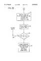
- FIGS. 2A-2Bis an overall flowchart for implementing a portion of the system of FIGS. 1A-1B.
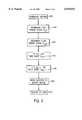
- FIG. 3is a flowchart showing a portion of FIGS. 2A-B in more detail.
- FIG. 4is a timing diagram showing an example of the implementation of a system in accordance with FIGS. 1a-b.
- FIG. 1a detailed circuit schematic of a system in accordance with the present invention is shown, including a pair of power supply switching networks 10 and 12 which provide selective power control to multiple zones of an induction heating coil 14.
- Switching network 10 and 12are identical, and therefore switching network 12 is shown in block diagram form for simplicity.
- the induction heating coil 14is sectioned into two half-sections 14A, 14B, one section being the lower half, and the other, the upper half.
- the switching networks 10, 12are connected to a single power supply 16 through a transformer 18 and a power storage or tank unit 20.
- the power storage unitcontains a bank of power factor correction capacitors 22 and a pair of relatively large inductors 24, 26, which are sized to provide a constant current to each active zone of the multi-zone induction heating coil 14.
- the bank of power factor correction caps 22also function to maintain a consistent operating frequency.
- the series connected inductors 24, 26are sized large enough to supply essentially a constant current to the induction heating coil 14 and switching networks 10, 12. There is a trade off in the size of the series inductors 24, 26 in that the larger the inductor, the higher the voltage requirement of the tuning capacitors 22 which increases the overall cost of the system, while an undersized inductor will create a dithering of the resonant frequency as the switches 28 are cycled. For cost effectiveness, it is therefore desirable to determine the smallest inductor that will maintain the resonant frequency. In a preferred embodiment, a value of 10 times the inductance of the induction heating coil 14 was adequate to provide essentially a constant current and maintain the resonant frequency stable as the switches 28 are cycled.
- Each switching network 10, 12has a number of bidirectional switches 28a, 28b, and 28c each connected in parallel with a portion of the induction heating coil 14 to thereby define a number of series connected induction heating coil zones 30, 32, 34 and 36, 38, 40.
- each of the bidirectional switches 28are connected in series with one another.
- Each of the bidirectional switches 28a, 28b, and 28c of switching networks 10 or 12has a pair of back-to-back, series connected switches 42, 44, which are preferably Insulated Gate Bipolar Transistors (IGBTs), but could be any bidirectional semiconductor switch properly rated for the particular application.
- IGBTsInsulated Gate Bipolar Transistors
- Each of the semiconductor switches 42, 44have a reversed biased diode 43 to allow a current path when the other associated semiconductor switch is ON to provide a current path away from the respective induction heating coil zones 30-40.
- IGBTswere chosen because of a desired operating frequency of 50 kHz and a current rating of over 1000 amps. At lower current levels, MOSFETS would be acceptable, and at lower operating frequencies, SCRs would be well suited. Similarly, for extremely slow cycling, one could also use simple relays for the bidirectional switches 28.
- One skilled in the artwill recognize that other equivalent switching means can be substituted depending upon application requirements.
- Each bidirectional switch 28is connected to an associated dual gate driver 46, each having a respective current sensor 48 connected to a primary current sensor 50 in operable association with the power supply feed line 52 for tracking current and voltage levels through the induction heating coils 30-34.
- These current sensors 48, 50enable the drivers 46 to switch the IGBTs 42, 44 at zero voltage crossing to prevent high switch losses. As one skilled in the art will readily recognize, such zero voltage switching would not be necessary if semiconductor switches having more ideal switching characteristics were used.
- each of the bidirectional switches 28 and series connected induction heating zones 30, 32, and 34have an RC snubber circuit 54 connected in parallel therewith.
- the snubber circuits 54are commonly known RC circuits for suppressing voltage spikes during the switching at the zero cross-over.
- a multi-zone feedback circuit 56is connected to each leg 58a, 58b, 58c and 60a, 60b, and 60c of each zone of the induction heating coil 14.
- the multi-zone feedback circuitry 56monitors voltage levels of each of the zones 30-40 via voltage lines 62, 64 and senses current via current lines 66, 68 through associated current sensors 70.
- the multi-zone feedback circuit 56provides multi-zone feedback to sense a fault condition on power supply legs 58, 60 within any of the zones 30-40 of the induction heating coil 14, and based on any detected fault, can interrupt or cause switching of any particular bidirectional switch 28 within the switching networks 10, 12.
- the multi-zone feedback circuit 56performs a voltage comparison between each leg to protect the bidirectional switches 28 from an overvoltage condition and can also monitor total power in each zone.
- the multi-zone feedbackwill set a fault condition if excess voltage is detected and also performs a voltage zero-crossing detection function to perform switching of the bidirectional switches 28 only during zero-crossing points, as previously described with respect to the preferred embodiment.
- a sync line 72 and a fault line 74are provided between the multi-zone feedback circuitry 56 and a fiber optic driver 76 to provide synchronous switching of the bidirectional switches 28 with the voltage zero-crossing points, and interrupt or enable switching during a fault, respectively.
- the fiber optic driver 76has fiber optic cables 78, 80 connected to and providing driving signals to each of the dual gate drivers 46 within the switching networks 10 and 12.
- the fiber optic driver 76provides isolation between the high voltage associated with the induction heating coil 14 and the driving logic controls.
- the fiber optic driver 76is connected to a computer 82 containing a processing unit which produces control signals to each of the bidirectional switches 28 through the fiber optic driver 76 and the dual gate drivers 46.
- the computer 82provides the control signals on six control lines 84 to the fiber optic driver 76, as well as providing fault and synchronous signals on a fault line 86 and a sync line 88, respectively.
- a 24 volt power supply 90provides 24 volt power to the fiber optic driver 76 and to internal relays in the computer 82.
- Transformer 92not only provides AC power to the 24 volt power supply 90, but also supplies 110 AC power to an internal power supply in computer 82 via power supply lines 94 and to a 36 volt current transformer 96 to supply power to the multi-zone feedback circuitry 56.
- Transformer 98provides power to each of the dual gate drivers 46.
- Inputs 83 to computer 82are received from an external control system for receiving a start signal for initializing the system.
- Output leads 85 of computer 82are input to the main power supply 16 and are used to determine the power level of the power supply output.
- Inputs 87are the zone reference control signals, which in the preferred embodiment, are 6 inputs from 6 separate temperature sensors that are placed in operative association with each coil zone 30-40 of the induction heating coil 14. These control signals 87 provide a closed loop feedback system to control the power to each individual zone. If the temperature is not high enough, as determined from inputs 87, the duty cycles are increased and/or the power supply power is increased via output 85 until the desired temperature is reached.
- each zone 30-40 of the induction heating coil 14is enabled when the bidirectional switch 28 is OFF. Conversely, turning the switch to the ON state, shorts out that particular zone of the coil and the power in that section drops.
- the power output of any one of the particular zones 30-40is then controlled by controlling the duty cycle of each particular switch 28.
- each zone of the coiloperates at approximately the same current. By cycling through the switches at a much faster rate than the response of the power supply, the power supply will run at the average total power. If the cycling rate were too low, the power supply can become unstable. The maximum cycling rate is then determined by the frequency selected for the coil.
- the overall function of the present inventionis to provide a stable AC current out of the tank section 20 and direct it either through the induction heating coil zones 30-40, or through the bidirectional switches 28, and thereby bypassing any particular zone of the heating coil 14.
- the currentflows around the coil section and through that IGBT 42 or 44, and through the other IGBT's associated diode 43 to thereby reduce the power in that zone.
- the IGBT's across a given zoneare gated OFF, the current is directed through the coil and the power is increased in that zone.
- the switching networks 10, 12are designed to be capable of turning ON and OFF for each half cycle.
- the systemuses 1,000 cycles as a base for all duty cycle calculations. The required total overall current and the individual duty cycles are calculated for each zone by computer 82. The power supply is then ramped up or down to the correct current level and the duty cycles are set accordingly. Each bidirectional switch 28 will then switch a number of times based on the duty cycle multiplied by the base 1,000 cycles.
- the computer controlis designed to maximize the cycling rate at any given duty cycle to stabilize the power supply and reduce the mechanical stresses on the coil. This is accomplished by spacing the ON pulses across 100 subsections of the 1,000 pulse base, and each of the subsections has 10 cycles of tank current, as will be further described with reference to FIG. 4. The software program optimizes this procedure by evenly distributing the ON pulses in the subsections.
- the duty cyclecalled for a 25% ON time
- the total cycleswould be 250 out of 1,000, and half of the subsections would be gated ON for 2 cycles and gated OFF for 8 cycles, and the other half would be gated ON for 3 cycles and OFF for 7 cycles. Therefore, in the 100 subsections of the 1,000 pulse base, the total cycles would be (50 ⁇ 2)+(50 ⁇ 3), or a total of 250 cycles.
- the duty cyclewere increased under this optimization procedure, first, each of the subcycles with 2 pulses would be increased to 3, before any of the subcycles with 3 pulses were increased to 4. Therefore, the ultimate cycling rate is 5 kHz, as opposed to 50 Hz.
- the following algorithmas described with reference to FIGS. 2A-2B describes a system according to the present invention for creating a modulation, as previously described, in 100 periods at 1/10 the frequency, or over a base total of 1,000 sections.
- the algorithmphase shifts the individual zone modulations by 1/200 of the base frequency with respect to each of the other zones. This phase shift provides an additional phase margin in the protection scheme for the frequency stability of the tank section.
- the time constant of the tank sectionis relatively unaffected and remains generally constant and within 1% of its base value.
- the system interruptsare enabled at 102, which will be further described with reference to FIG. 3.
- the next step in the algorithm of the computer software programis to read the temperature feedback inputs 87, FIG. 1B, at 104, FIG. 2A.
- Each signal inputis then normalized to a base of 1,000 at 106 and a clocked loop begins at 108.
- the largest of the normalized signalsis determined at 112 and compared to the largest normalized signal during a previous iteration 114.
- the power supply registeris incremented at 118 and each normalized signal is divided by that last largest normalized signal 120.
- each of the normalized signalsis divided by the largest normalized signal at 120. Then, as continued on FIG. 2B, the algorithm multiplies each of the normalized signals by 100 and divides the results by 1,000 to calculate the duty cycles by finding the quotient Q ns and remainder R ns for each normalized signal at 128.
- a look up tableis produced for the bidirectional switch outputs at 130 and a check is made to see if the computer has received a stop or fault signal 132, and if so, the interrupts are disabled, each of the bidirectional switches are closed, and a shutdown routine is run to bring the power supply down at 134. If no stop or fault is detected at 132, then the system proceeds through path 136 to perform another iteration beginning with reading the inputs at 104.
- the quotient Q ns and the remainder R nsare used in distributing the ON times over the 100 subsections. The Q ns is evenly distributed, and the R ns is periodically distributed throughout the 100 subsections.
- a custom interrupt handleris initiated at 140 because of the need of quicker interrupts than normally provided in standard computers.
- Two internal machine clocksare generated, one to track the aforementioned 100 periods T 100 and one to track the 10 subperiods T 10 .
- the period clocks T 10 and T 100are each incremented 142, 144 and if either clock has reached its maximum, it is reset at 146, 148.
- the quotient Q nsis evenly distributed over the 100 subsections, and the remainder R ns is periodically distributed over the 100 periods for even average distribution of ON times.
- the outputsare then updated.
- One output, the power level,is written from the power supply register to a power supply interface to control the main power supply 150, and the individual switch control outputs are updated by pointing to an output table created by the main algorithm as previously described.
- the interruptis generated by the frequency of the tank circuit 20 and allows synchronous control of the switching.
- the systemUpon completion of the updates, the system returns 152 to the main algorithm 100 of FIG. 2A.
- the first zone Z 1is shown having a 55% duty cycle. In 1,000 cycles, a 55% duty cycle multiplied by 100 and divided by 1,000 provides a quotient of 5 and a remainder of 5. As shown if FIG. 4, zone 1 is ON for 5 clocks 160 for each of the 100 periods. The remainder 162 is distributed throughout the 100 periods to create an even total average.
- the timing diagramalso shows ON time distributions for zone 2 Z 2 at a 20% duty cycle 164 and for zone 3 Z 3 at a 40% duty cycle 166. For both 20% and 40% duty cycles, there is no remainder, so the quotient is easily distributed over the 100 periods 164, 166.
- each subsequent ON state 164, 166is phase shifted from the previous in order to provide an even ON time distribution for each subperiod so that the main power supply can be derated as much as possible.
- timing diagrams for the remaining zoneswould alternately phase shift the ON states to provide an even distribution of the ON states across the clock subperiods.
- the present inventionalso includes a method of providing individual power control to multiple sections of an induction heating coil including the steps of tapping each section into a number of series connected zones within the induction heating coil and periodically or intermittently switching a current path around each of the zones such that the power and heat output of each zone is regulated, and the entire induction heating coil can provide even heat distribution to a workpiece.
- Each of the switchable current pathsare in series with one another as well as the respective zones of the induction heating coil. In this manner, an induction heating coil need not be physically altered, but can be divided into as many sections as desired for providing consistent and even heat distribution.
- the method of the present inventionalso includes sensing current in each power supply side of each zone, and detecting faults, such as overvoltage, and interrupting or causing switching in response to a fault detection.
- the systemalso optimizes distribution of ON times to reduce overall output requirements of the main power supply.
Landscapes
- Physics & Mathematics (AREA)
- Electromagnetism (AREA)
- General Induction Heating (AREA)
Abstract
Description
Claims (42)
Priority Applications (1)
| Application Number | Priority Date | Filing Date | Title |
|---|---|---|---|
| US09/086,901US6078033A (en) | 1998-05-29 | 1998-05-29 | Multi-zone induction heating system with bidirectional switching network |
Applications Claiming Priority (1)
| Application Number | Priority Date | Filing Date | Title |
|---|---|---|---|
| US09/086,901US6078033A (en) | 1998-05-29 | 1998-05-29 | Multi-zone induction heating system with bidirectional switching network |
Publications (1)
| Publication Number | Publication Date |
|---|---|
| US6078033Atrue US6078033A (en) | 2000-06-20 |
Family
ID=22201640
Family Applications (1)
| Application Number | Title | Priority Date | Filing Date |
|---|---|---|---|
| US09/086,901Expired - LifetimeUS6078033A (en) | 1998-05-29 | 1998-05-29 | Multi-zone induction heating system with bidirectional switching network |
Country Status (1)
| Country | Link |
|---|---|
| US (1) | US6078033A (en) |
Cited By (23)
| Publication number | Priority date | Publication date | Assignee | Title |
|---|---|---|---|---|
| WO2002027908A1 (en)* | 2000-09-29 | 2002-04-04 | Efd Induction A.S. | High output power high frequency resonant load inverters |
| US6412252B1 (en) | 1996-11-15 | 2002-07-02 | Kaps-All Packaging Systems, Inc. | Slotted induction heater |
| US6415128B1 (en)* | 1999-09-22 | 2002-07-02 | Toshiba Tec Kabushiki Kaisha | Fixing device |
| US6633480B1 (en) | 1997-11-07 | 2003-10-14 | Kenneth J. Herzog | Air-cooled induction foil cap sealer |
| US20040104217A1 (en)* | 2000-08-31 | 2004-06-03 | Herzog Kenneth J. | Multiple head induction sealer apparatus and method |
| US20050111518A1 (en)* | 2003-11-07 | 2005-05-26 | Roach Jay A. | Induction coil configurations, bottom drain assemblies, and high-temperature head assemblies for induction melter apparatus and methods of control and design therefor |
| US20060050761A1 (en)* | 2004-08-25 | 2006-03-09 | Richardson John G | Induction heating apparatus, methods of operation thereof, and method for indication of a temperature of a material to be heated therewith |
| US20060050762A1 (en)* | 2004-08-25 | 2006-03-09 | Richardson John G | Induction heating apparatus and methods of operation thereof |
| US20060205348A1 (en)* | 2005-03-11 | 2006-09-14 | Maxwell James W | Mounting pedestal for a cellular signal enhancer |
| US7323666B2 (en) | 2003-12-08 | 2008-01-29 | Saint-Gobain Performance Plastics Corporation | Inductively heatable components |
| US20100296521A1 (en)* | 2009-05-22 | 2010-11-25 | Canon Kabushiki Kaisha | Efficient bandwidth utilization when streaming data over multiple network interfaces |
| EP2520416A1 (en)* | 2011-05-05 | 2012-11-07 | Tetra Laval Holdings & Finance S.A. | Induction sealing device for heat sealing packaging material for producing sealed packages of pourable food products |
| US8939695B2 (en) | 2011-06-16 | 2015-01-27 | Sonoco Development, Inc. | Method for applying a metal end to a container body |
| US20150048080A1 (en)* | 2008-09-15 | 2015-02-19 | The Boeing Company | Methods for fabrication of thermoplastic components |
| US8998027B2 (en) | 2011-09-02 | 2015-04-07 | Sonoco Development, Inc. | Retort container with thermally fused double-seamed or crimp-seamed metal end |
| US10131455B2 (en) | 2011-10-28 | 2018-11-20 | Sonoco Development, Inc. | Apparatus and method for induction sealing of conveyed workpieces |
| US10399139B2 (en) | 2012-04-12 | 2019-09-03 | Sonoco Development, Inc. | Method of making a retort container |
| US10605464B2 (en) | 2012-10-15 | 2020-03-31 | Whirlpool Corporation | Induction cooktop |
| US10893579B2 (en) | 2017-07-18 | 2021-01-12 | Whirlpool Corporation | Method for operating an induction cooking hob and cooking hob using such method |
| US10993292B2 (en) | 2017-10-23 | 2021-04-27 | Whirlpool Corporation | System and method for tuning an induction circuit |
| US11140751B2 (en) | 2018-04-23 | 2021-10-05 | Whirlpool Corporation | System and method for controlling quasi-resonant induction heating devices |
| US11212880B2 (en) | 2012-10-15 | 2021-12-28 | Whirlpool Emea S.P.A. | Induction cooking top |
| US12302478B2 (en) | 2018-04-23 | 2025-05-13 | Whirlpool Corporation | Control circuits and methods for distributed induction heating devices |
Citations (14)
| Publication number | Priority date | Publication date | Assignee | Title |
|---|---|---|---|---|
| US1981631A (en)* | 1931-01-05 | 1934-11-20 | Ajax Electrothermic Corp | Electric induction furnace |
| US3708645A (en)* | 1971-10-12 | 1973-01-02 | Park Ohio Industries Inc | Method of heating a workpiece of particulate material |
| US3925633A (en)* | 1974-09-06 | 1975-12-09 | Donald F Partridge | Circuit for controlling power flow from a high frequency energy source to a plurality of high frequency loads |
| US4058696A (en)* | 1975-06-17 | 1977-11-15 | Tocco-Stel | Induction heating apparatus comprising a static converter |
| US4074101A (en)* | 1975-02-14 | 1978-02-14 | Matsushita Electric Industrial Co., Ltd. | Induction heating apparatus using a pair of inversely parallel connected gate-controlled switching devices |
| US4114009A (en)* | 1976-02-03 | 1978-09-12 | Matsushita Electric Industrial Co., Ltd. | Switching and heat control mechanism for induction heating cooking apparatus having a plurality of work coils |
| US4317975A (en)* | 1976-01-14 | 1982-03-02 | Matsushita Electric Industrial Co., Ltd. | Induction heating apparatus with means for detecting zero crossing point of high-frequency oscillation to determine triggering time |
| US4506131A (en)* | 1983-08-29 | 1985-03-19 | Inductotherm Industries Inc. | Multiple zone induction coil power control apparatus and method |
| US4816633A (en)* | 1987-03-06 | 1989-03-28 | Tocco, Inc. | Method of monitoring induction heating cycle |
| US4845332A (en)* | 1987-09-16 | 1989-07-04 | National Steel Corp. | Galvanneal induction furnace temperature control system |
| US5059762A (en)* | 1989-10-31 | 1991-10-22 | Inductotherm Europe Limited | Multiple zone induction heating |
| US5349167A (en)* | 1992-08-06 | 1994-09-20 | Indecctotherm Europe Limited | Induction heating apparatus with PWM multiple zone heating control |
| US5892677A (en)* | 1997-06-02 | 1999-04-06 | Reliance Electric Industrial Company | Adaptive overlapping communication control of modular AC-AC converter and integration with device module of multiple AC-AC switches |
| US5909367A (en)* | 1997-06-02 | 1999-06-01 | Reliance Electric Industrial Company | Modular AC-AC variable voltage and variable frequency power conveter system and control |
- 1998
- 1998-05-29USUS09/086,901patent/US6078033A/ennot_activeExpired - Lifetime
Patent Citations (14)
| Publication number | Priority date | Publication date | Assignee | Title |
|---|---|---|---|---|
| US1981631A (en)* | 1931-01-05 | 1934-11-20 | Ajax Electrothermic Corp | Electric induction furnace |
| US3708645A (en)* | 1971-10-12 | 1973-01-02 | Park Ohio Industries Inc | Method of heating a workpiece of particulate material |
| US3925633A (en)* | 1974-09-06 | 1975-12-09 | Donald F Partridge | Circuit for controlling power flow from a high frequency energy source to a plurality of high frequency loads |
| US4074101A (en)* | 1975-02-14 | 1978-02-14 | Matsushita Electric Industrial Co., Ltd. | Induction heating apparatus using a pair of inversely parallel connected gate-controlled switching devices |
| US4058696A (en)* | 1975-06-17 | 1977-11-15 | Tocco-Stel | Induction heating apparatus comprising a static converter |
| US4317975A (en)* | 1976-01-14 | 1982-03-02 | Matsushita Electric Industrial Co., Ltd. | Induction heating apparatus with means for detecting zero crossing point of high-frequency oscillation to determine triggering time |
| US4114009A (en)* | 1976-02-03 | 1978-09-12 | Matsushita Electric Industrial Co., Ltd. | Switching and heat control mechanism for induction heating cooking apparatus having a plurality of work coils |
| US4506131A (en)* | 1983-08-29 | 1985-03-19 | Inductotherm Industries Inc. | Multiple zone induction coil power control apparatus and method |
| US4816633A (en)* | 1987-03-06 | 1989-03-28 | Tocco, Inc. | Method of monitoring induction heating cycle |
| US4845332A (en)* | 1987-09-16 | 1989-07-04 | National Steel Corp. | Galvanneal induction furnace temperature control system |
| US5059762A (en)* | 1989-10-31 | 1991-10-22 | Inductotherm Europe Limited | Multiple zone induction heating |
| US5349167A (en)* | 1992-08-06 | 1994-09-20 | Indecctotherm Europe Limited | Induction heating apparatus with PWM multiple zone heating control |
| US5892677A (en)* | 1997-06-02 | 1999-04-06 | Reliance Electric Industrial Company | Adaptive overlapping communication control of modular AC-AC converter and integration with device module of multiple AC-AC switches |
| US5909367A (en)* | 1997-06-02 | 1999-06-01 | Reliance Electric Industrial Company | Modular AC-AC variable voltage and variable frequency power conveter system and control |
Cited By (51)
| Publication number | Priority date | Publication date | Assignee | Title |
|---|---|---|---|---|
| US6747252B2 (en) | 1996-11-15 | 2004-06-08 | Kenneth J. Herzog | Multiple head induction sealer apparatus and method |
| US6732495B2 (en) | 1996-11-15 | 2004-05-11 | Kaps-All Packaging Systems Inc. | Induction foil cap sealer |
| US7065941B2 (en) | 1996-11-15 | 2006-06-27 | Kaps-All Packaging Systems Inc. | Induction foil cap sealer |
| US20040200194A1 (en)* | 1996-11-15 | 2004-10-14 | Kaps-All Packaging Systems, Inc. | Induction foil cap sealer |
| US6629399B2 (en) | 1996-11-15 | 2003-10-07 | Kaps-All Packaging Systems Inc. | Induction foil cap sealer employing litz wire coil |
| US6412252B1 (en) | 1996-11-15 | 2002-07-02 | Kaps-All Packaging Systems, Inc. | Slotted induction heater |
| US6633480B1 (en) | 1997-11-07 | 2003-10-14 | Kenneth J. Herzog | Air-cooled induction foil cap sealer |
| US6415128B1 (en)* | 1999-09-22 | 2002-07-02 | Toshiba Tec Kabushiki Kaisha | Fixing device |
| US20040104217A1 (en)* | 2000-08-31 | 2004-06-03 | Herzog Kenneth J. | Multiple head induction sealer apparatus and method |
| US6875965B2 (en) | 2000-08-31 | 2005-04-05 | Kenneth J. Herzog | Multiple head induction sealer apparatus and method |
| US6842355B2 (en) | 2000-09-29 | 2005-01-11 | Efd Induction A.S. | High output power high frequency resonant load inverters |
| US20030179595A1 (en)* | 2000-09-29 | 2003-09-25 | Frode Kleveland | High output power high frequency resonant load inverters |
| WO2002027908A1 (en)* | 2000-09-29 | 2002-04-04 | Efd Induction A.S. | High output power high frequency resonant load inverters |
| US20060239327A1 (en)* | 2003-11-07 | 2006-10-26 | Roach Jay A | Induction melter apparatus |
| US20050111518A1 (en)* | 2003-11-07 | 2005-05-26 | Roach Jay A. | Induction coil configurations, bottom drain assemblies, and high-temperature head assemblies for induction melter apparatus and methods of control and design therefor |
| US6993061B2 (en) | 2003-11-07 | 2006-01-31 | Battelle Energy Alliance, Llc | Operating an induction melter apparatus |
| US7388896B2 (en) | 2003-11-07 | 2008-06-17 | Battelle Energy Alliance, Llc | Induction melter apparatus |
| US7745355B2 (en) | 2003-12-08 | 2010-06-29 | Saint-Gobain Performance Plastics Corporation | Inductively heatable components |
| US7323666B2 (en) | 2003-12-08 | 2008-01-29 | Saint-Gobain Performance Plastics Corporation | Inductively heatable components |
| US20060050761A1 (en)* | 2004-08-25 | 2006-03-09 | Richardson John G | Induction heating apparatus, methods of operation thereof, and method for indication of a temperature of a material to be heated therewith |
| US20060050762A1 (en)* | 2004-08-25 | 2006-03-09 | Richardson John G | Induction heating apparatus and methods of operation thereof |
| US7085305B2 (en) | 2004-08-25 | 2006-08-01 | Battelle Energy Alliance, Llc | Induction heating apparatus and methods of operation thereof |
| US7072378B2 (en) | 2004-08-25 | 2006-07-04 | Battelle Energy Alliance, Llc | Induction heating apparatus and methods for selectively energizing an inductor in response to a measured electrical characteristic that is at least partially a function of a temperature of a material being heated |
| US20060205348A1 (en)* | 2005-03-11 | 2006-09-14 | Maxwell James W | Mounting pedestal for a cellular signal enhancer |
| US7333771B2 (en)* | 2005-03-11 | 2008-02-19 | Andrew Corporation | Mounting pedestal for a cellular signal enhancer |
| US20150048080A1 (en)* | 2008-09-15 | 2015-02-19 | The Boeing Company | Methods for fabrication of thermoplastic components |
| US10219329B2 (en)* | 2008-09-15 | 2019-02-26 | The Boeing Company | Methods for fabrication of thermoplastic components |
| US8068514B2 (en) | 2009-05-22 | 2011-11-29 | Canon Kabushiki Kaisha | Efficient bandwidth utilization when streaming data over multiple network interfaces |
| US20100296521A1 (en)* | 2009-05-22 | 2010-11-25 | Canon Kabushiki Kaisha | Efficient bandwidth utilization when streaming data over multiple network interfaces |
| WO2012150148A1 (en)* | 2011-05-05 | 2012-11-08 | Tetra Laval Holdings & Finance S.A. | Induction sealing device for heat sealing packaging material for producing sealed packages of pourable food products |
| CN103501982A (en)* | 2011-05-05 | 2014-01-08 | 利乐拉瓦尔集团及财务有限公司 | Induction sealing device for heat sealing packaging material for producing sealed packages of pourable food products |
| EP2520416A1 (en)* | 2011-05-05 | 2012-11-07 | Tetra Laval Holdings & Finance S.A. | Induction sealing device for heat sealing packaging material for producing sealed packages of pourable food products |
| US8939695B2 (en) | 2011-06-16 | 2015-01-27 | Sonoco Development, Inc. | Method for applying a metal end to a container body |
| US9783337B2 (en) | 2011-09-02 | 2017-10-10 | Sonoco Development, Inc. | Container with thermally fused double-seamed or crimp-seamed metal end |
| US9988179B2 (en) | 2011-09-02 | 2018-06-05 | Sonoco Development, Inc. | Container with thermally fused double-seamed or crimp-seamed metal end |
| US8998027B2 (en) | 2011-09-02 | 2015-04-07 | Sonoco Development, Inc. | Retort container with thermally fused double-seamed or crimp-seamed metal end |
| US10259612B2 (en) | 2011-09-02 | 2019-04-16 | Sonoco Development, Inc. | Container with thermally fused double-seamed or crimp-seamed metal end |
| US9499299B2 (en) | 2011-09-02 | 2016-11-22 | Sonoco Development, Inc. | Container with thermally fused double-seamed or crimp-seamed metal end |
| US10994888B2 (en) | 2011-09-02 | 2021-05-04 | Sonoco Development, Inc. | Container with thermally fused double-seamed or crimp-seamed metal end |
| US10131455B2 (en) | 2011-10-28 | 2018-11-20 | Sonoco Development, Inc. | Apparatus and method for induction sealing of conveyed workpieces |
| US10399139B2 (en) | 2012-04-12 | 2019-09-03 | Sonoco Development, Inc. | Method of making a retort container |
| US10569324B2 (en) | 2012-04-12 | 2020-02-25 | Sonoco Development, Inc. | Method of making a retort container |
| US11040495B2 (en) | 2012-04-12 | 2021-06-22 | Sonoco Development, Inc | Method of making a retort container |
| US11212880B2 (en) | 2012-10-15 | 2021-12-28 | Whirlpool Emea S.P.A. | Induction cooking top |
| US10605464B2 (en) | 2012-10-15 | 2020-03-31 | Whirlpool Corporation | Induction cooktop |
| US11655984B2 (en) | 2012-10-15 | 2023-05-23 | Whirlpool Corporation | Induction cooktop |
| US10893579B2 (en) | 2017-07-18 | 2021-01-12 | Whirlpool Corporation | Method for operating an induction cooking hob and cooking hob using such method |
| US10993292B2 (en) | 2017-10-23 | 2021-04-27 | Whirlpool Corporation | System and method for tuning an induction circuit |
| US11140751B2 (en) | 2018-04-23 | 2021-10-05 | Whirlpool Corporation | System and method for controlling quasi-resonant induction heating devices |
| US12245348B2 (en) | 2018-04-23 | 2025-03-04 | Whirlpool Corporation | System and method for controlling quasi-resonant induction heating devices |
| US12302478B2 (en) | 2018-04-23 | 2025-05-13 | Whirlpool Corporation | Control circuits and methods for distributed induction heating devices |
Similar Documents
| Publication | Publication Date | Title |
|---|---|---|
| US6078033A (en) | Multi-zone induction heating system with bidirectional switching network | |
| EP0641145B1 (en) | Control system for powering plural inductive loads from a single inverter source | |
| US5781419A (en) | Soft switching DC-to-DC converter with coupled inductors | |
| EP0554443B1 (en) | Induction heater | |
| US6163019A (en) | Resonant frequency induction furnace system using capacitive voltage division | |
| EP2815306B1 (en) | Programmable gate controller system and method | |
| EP2589139B1 (en) | Feed forward control for a cyclo-converter | |
| WO1995030182A1 (en) | High-efficiency power supply | |
| US5621305A (en) | Overload management system | |
| GB2350733A (en) | Power supply having reduced 2nd harmonics and a filter having a roll-off frequency close to the design frequency of the load circuit. | |
| US5534766A (en) | Fuzzy logic power supply controller | |
| CN104335469A (en) | Controlling a switched mode power supply with maximised power efficiency | |
| WO1994024752A1 (en) | Modular thyristor controlled series capacitor control system | |
| WO2016025763A1 (en) | Integrated thermal and power control | |
| JP2016536723A (en) | Switching topology for connecting two nodes in an electronic system | |
| US5856740A (en) | Shunt voltage regulator with a variable load unit | |
| US4392172A (en) | Reactive snubber for inductive load clamp diodes | |
| EP3721522B1 (en) | System and method for high efficiency power quality correction | |
| CN104638934A (en) | Matrix converter and method for compensating for output voltage error | |
| FI981686A0 (en) | Arrangement to eliminate radio interference in the electronic power controller | |
| US11664741B2 (en) | System and method for AC power control | |
| CN115792697B (en) | A three-phase analog pulse load with high precision and high dynamic response | |
| US9484806B2 (en) | Driving apparatus for driving power factor correction circuit | |
| JP2003513603A (en) | Static regulator | |
| Lunardon et al. | Control strategy for the magnetic energy storage and transfer system (MEST) |
Legal Events
| Date | Code | Title | Description |
|---|---|---|---|
| AS | Assignment | Owner name:PILLAR INDUSTRIES, INC., WISCONSIN Free format text:ASSIGNMENT OF ASSIGNORS INTEREST;ASSIGNORS:BOWERS, THOMAS J.;DER, CHUCK F.;PARKER, JAMES D.;REEL/FRAME:009394/0610 Effective date:19980812 | |
| STCF | Information on status: patent grant | Free format text:PATENTED CASE | |
| CC | Certificate of correction | ||
| AS | Assignment | Owner name:PILLAR INDUCTION COMPANY, LLC, ILLINOIS Free format text:ASSIGNMENT OF ASSIGNORS INTEREST;ASSIGNOR:PILLAR INDUSTRIES, A DIVISION OF PILLAR CORPORATION;REEL/FRAME:013634/0895 Effective date:20021231 | |
| AS | Assignment | Owner name:LASALLE BUSINESS CREDIT, LLC, ILLINOIS Free format text:PATENT SECURITY AGREEMENT;ASSIGNOR:PILLAR INDUCTION COMPANY, LLC;REEL/FRAME:013791/0034 Effective date:20021231 | |
| FPAY | Fee payment | Year of fee payment:4 | |
| FEPP | Fee payment procedure | Free format text:PAYER NUMBER DE-ASSIGNED (ORIGINAL EVENT CODE: RMPN); ENTITY STATUS OF PATENT OWNER: LARGE ENTITY | |
| FPAY | Fee payment | Year of fee payment:8 | |
| AS | Assignment | Owner name:ABP INDUCTION, LLC, NEW JERSEY Free format text:ASSIGNMENT OF ASSIGNORS INTEREST;ASSIGNOR:PILLAR INDUCTION COMPANY, LLC;REEL/FRAME:020417/0034 Effective date:20080121 | |
| AS | Assignment | Owner name:PILLAR INDUCTION COMPANY, LLC, WISCONSIN Free format text:RELEASE BY SECURED PARTY;ASSIGNOR:LASALLE BUSINESS CREDIT, LLC;REEL/FRAME:020478/0431 Effective date:20080206 | |
| AS | Assignment | Owner name:WESTLB AG, NEW YORK BRANCH, NEW YORK Free format text:SECURITY AGREEMENT;ASSIGNOR:ABP INDUCTION, LLC;REEL/FRAME:020555/0133 Effective date:20080209 | |
| AS | Assignment | Owner name:ABP INDUCTION, LLC, ILLINOIS Free format text:RELEASE BY SECURED PARTY;ASSIGNOR:WESTLB AG;REEL/FRAME:026648/0395 Effective date:20110517 Owner name:AJAX MAGNETHERMIC CORPORATION, OHIO Free format text:ASSIGNMENT OF ASSIGNORS INTEREST;ASSIGNOR:ABP INDUCTION LLC;REEL/FRAME:026647/0095 Effective date:20101231 | |
| AS | Assignment | Owner name:AJAX TOCCO MAGNETHERMIC CORPORATION, OHIO Free format text:CORRECTIVE ASSIGNMENT TO CORRECT THE ASSIGNEE NAME PREVIOUSLY RECORDED ON REEL 026647 FRAME 0095. ASSIGNOR(S) HEREBY CONFIRMS THE CORRECT ASSIGNEE NAME IS AJAX TOCCO MAGNETHERMIC CORPORATION;ASSIGNOR:ABP INDUCTION, LLC;REEL/FRAME:026724/0947 Effective date:20101231 | |
| FPAY | Fee payment | Year of fee payment:12 | |
| FEPP | Fee payment procedure | Free format text:PAT HOLDER NO LONGER CLAIMS SMALL ENTITY STATUS, ENTITY STATUS SET TO UNDISCOUNTED (ORIGINAL EVENT CODE: STOL); ENTITY STATUS OF PATENT OWNER: LARGE ENTITY | |
| REFU | Refund | Free format text:REFUND - PAYMENT OF MAINTENANCE FEE, 12TH YR, SMALL ENTITY (ORIGINAL EVENT CODE: R2553); ENTITY STATUS OF PATENT OWNER: LARGE ENTITY | |
| FPAY | Fee payment | Year of fee payment:12 | |
| SULP | Surcharge for late payment | Year of fee payment:11 | |
| AS | Assignment | Owner name:JPMORGAN CHASE BANK, N.A., AS ADMINISTRATIVE AGENT Free format text:SECURITY AGREEMENT;ASSIGNORS:AJAX TOCCO MAGNETHERMIC CORPORATION;ILS TECHNOLOGY LLC;PARK-OHIO INDUSTRIES, INC.;AND OTHERS;REEL/FRAME:027923/0635 Effective date:20120323 | |
| FEPP | Fee payment procedure | Free format text:PAYOR NUMBER ASSIGNED (ORIGINAL EVENT CODE: ASPN); ENTITY STATUS OF PATENT OWNER: LARGE ENTITY |