US6077296A - Endoluminal vascular prosthesis - Google Patents
Endoluminal vascular prosthesisDownload PDFInfo
- Publication number
- US6077296A US6077296AUS09/034,689US3468998AUS6077296AUS 6077296 AUS6077296 AUS 6077296AUS 3468998 AUS3468998 AUS 3468998AUS 6077296 AUS6077296 AUS 6077296A
- Authority
- US
- United States
- Prior art keywords
- prosthesis
- tubular
- proximal
- segment
- bends
- Prior art date
- Legal status (The legal status is an assumption and is not a legal conclusion. Google has not performed a legal analysis and makes no representation as to the accuracy of the status listed.)
- Expired - Lifetime
Links
- 230000002792vascularEffects0.000titleclaimsabstractdescription27
- 238000000034methodMethods0.000claimsabstractdescription14
- 230000010412perfusionEffects0.000claimsdescription12
- 230000002829reductive effectEffects0.000claimsdescription11
- 238000011282treatmentMethods0.000claimsdescription9
- 229920001343polytetrafluoroethylenePolymers0.000claimsdescription8
- 239000004810polytetrafluoroethyleneSubstances0.000claimsdescription8
- 229910052751metalInorganic materials0.000claimsdescription5
- 239000002184metalSubstances0.000claimsdescription5
- 239000013047polymeric layerSubstances0.000claimsdescription5
- 238000002513implantationMethods0.000claimsdescription4
- 238000005096rolling processMethods0.000claimsdescription4
- 238000004519manufacturing processMethods0.000claimsdescription2
- 239000010410layerSubstances0.000claims1
- 208000002223abdominal aortic aneurysmDiseases0.000abstractdescription14
- 208000007474aortic aneurysmDiseases0.000abstractdescription9
- 239000012528membraneSubstances0.000abstract1
- 206010002329AneurysmDiseases0.000description30
- 210000002254renal arteryAnatomy0.000description22
- 210000000709aortaAnatomy0.000description19
- 238000001356surgical procedureMethods0.000description13
- 239000000463materialSubstances0.000description12
- 238000013461designMethods0.000description10
- 210000001367arteryAnatomy0.000description8
- 210000000702aorta abdominalAnatomy0.000description7
- 230000004323axial lengthEffects0.000description7
- 230000003187abdominal effectEffects0.000description6
- 238000004873anchoringMethods0.000description5
- 208000007536ThrombosisDiseases0.000description4
- 210000001015abdomenAnatomy0.000description4
- 229910045601alloyInorganic materials0.000description4
- 239000000956alloySubstances0.000description4
- 210000003090iliac arteryAnatomy0.000description4
- 229920004934Dacron®Polymers0.000description3
- PXHVJJICTQNCMI-UHFFFAOYSA-NNickelChemical compound[Ni]PXHVJJICTQNCMI-UHFFFAOYSA-N0.000description3
- 210000003484anatomyAnatomy0.000description3
- 230000008901benefitEffects0.000description3
- 210000000038chestAnatomy0.000description3
- 230000003247decreasing effectEffects0.000description3
- 210000002216heartAnatomy0.000description3
- 230000005012migrationEffects0.000description3
- 238000013508migrationMethods0.000description3
- 229920000728polyesterPolymers0.000description3
- 230000000452restraining effectEffects0.000description3
- 239000010935stainless steelSubstances0.000description3
- 229910001220stainless steelInorganic materials0.000description3
- JOYRKODLDBILNP-UHFFFAOYSA-NEthyl urethaneChemical compoundCCOC(N)=OJOYRKODLDBILNP-UHFFFAOYSA-N0.000description2
- 239000004677NylonSubstances0.000description2
- 229920006362Teflon®Polymers0.000description2
- 238000013459approachMethods0.000description2
- 239000008280bloodSubstances0.000description2
- 210000004369bloodAnatomy0.000description2
- 230000017531blood circulationEffects0.000description2
- 230000010261cell growthEffects0.000description2
- 239000011248coating agentSubstances0.000description2
- 238000000576coating methodMethods0.000description2
- 230000006835compressionEffects0.000description2
- 238000007906compressionMethods0.000description2
- 210000002889endothelial cellAnatomy0.000description2
- 230000003511endothelial effectEffects0.000description2
- 230000012010growthEffects0.000description2
- 208000017169kidney diseaseDiseases0.000description2
- 210000004185liverAnatomy0.000description2
- 210000004072lungAnatomy0.000description2
- 239000003550markerSubstances0.000description2
- 238000012986modificationMethods0.000description2
- 230000004048modificationEffects0.000description2
- 229910052759nickelInorganic materials0.000description2
- 229910001000nickel titaniumInorganic materials0.000description2
- HLXZNVUGXRDIFK-UHFFFAOYSA-Nnickel titaniumChemical compound[Ti].[Ti].[Ti].[Ti].[Ti].[Ti].[Ti].[Ti].[Ti].[Ti].[Ti].[Ni].[Ni].[Ni].[Ni].[Ni].[Ni].[Ni].[Ni].[Ni].[Ni].[Ni].[Ni].[Ni].[Ni]HLXZNVUGXRDIFK-UHFFFAOYSA-N0.000description2
- 229920001778nylonPolymers0.000description2
- 239000005020polyethylene terephthalateSubstances0.000description2
- 230000008439repair processEffects0.000description2
- 238000004904shorteningMethods0.000description2
- 230000002381testicularEffects0.000description2
- 210000001042thoracic arteryAnatomy0.000description2
- 238000011144upstream manufacturingMethods0.000description2
- 208000017667Chronic DiseaseDiseases0.000description1
- 208000034657ConvalescenceDiseases0.000description1
- 229910000599Cr alloyInorganic materials0.000description1
- 238000012276Endovascular treatmentMethods0.000description1
- 208000008952Iliac AneurysmDiseases0.000description1
- 229910001182Mo alloyInorganic materials0.000description1
- 239000004698PolyethyleneSubstances0.000description1
- 239000004743PolypropyleneSubstances0.000description1
- 239000004809TeflonSubstances0.000description1
- RTAQQCXQSZGOHL-UHFFFAOYSA-NTitaniumChemical compound[Ti]RTAQQCXQSZGOHL-UHFFFAOYSA-N0.000description1
- 210000000683abdominal cavityAnatomy0.000description1
- 210000003815abdominal wallAnatomy0.000description1
- 230000002159abnormal effectEffects0.000description1
- 239000000853adhesiveSubstances0.000description1
- 230000001070adhesive effectEffects0.000description1
- 230000003466anti-cipated effectEffects0.000description1
- 230000005540biological transmissionEffects0.000description1
- 230000015572biosynthetic processEffects0.000description1
- 210000004204blood vesselAnatomy0.000description1
- 229910052804chromiumInorganic materials0.000description1
- OGSYQYXYGXIQFH-UHFFFAOYSA-Nchromium molybdenum nickelChemical compound[Cr].[Ni].[Mo]OGSYQYXYGXIQFH-UHFFFAOYSA-N0.000description1
- 230000008878couplingEffects0.000description1
- 238000010168coupling processMethods0.000description1
- 238000005859coupling reactionMethods0.000description1
- 238000004132cross linkingMethods0.000description1
- JXSJBGJIGXNWCI-UHFFFAOYSA-Ndiethyl 2-[(dimethoxyphosphorothioyl)thio]succinateChemical compoundCCOC(=O)CC(SP(=S)(OC)OC)C(=O)OCCJXSJBGJIGXNWCI-UHFFFAOYSA-N0.000description1
- 230000000916dilatatory effectEffects0.000description1
- 230000010339dilationEffects0.000description1
- 238000007598dipping methodMethods0.000description1
- 238000009826distributionMethods0.000description1
- 239000003814drugSubstances0.000description1
- 229940079593drugDrugs0.000description1
- 229910000701elgiloys (Co-Cr-Ni Alloy)Inorganic materials0.000description1
- 239000000835fiberSubstances0.000description1
- 239000012530fluidSubstances0.000description1
- 230000002706hydrostatic effectEffects0.000description1
- 238000011065in-situ storageMethods0.000description1
- 210000000936intestineAnatomy0.000description1
- 210000003734kidneyAnatomy0.000description1
- 210000005240left ventricleAnatomy0.000description1
- 230000003902lesionEffects0.000description1
- 230000014759maintenance of locationEffects0.000description1
- 239000011159matrix materialSubstances0.000description1
- 150000002739metalsChemical class0.000description1
- 239000000203mixtureSubstances0.000description1
- 229910052750molybdenumInorganic materials0.000description1
- 238000012544monitoring processMethods0.000description1
- 238000002355open surgical procedureMethods0.000description1
- 210000000056organAnatomy0.000description1
- 210000004197pelvisAnatomy0.000description1
- 229920009441perflouroethylene propylenePolymers0.000description1
- 210000004303peritoneumAnatomy0.000description1
- 230000035699permeabilityEffects0.000description1
- 230000000704physical effectEffects0.000description1
- 229920000139polyethylene terephthalatePolymers0.000description1
- -1polypropylenePolymers0.000description1
- 229920001155polypropylenePolymers0.000description1
- 239000011148porous materialSubstances0.000description1
- 230000000750progressive effectEffects0.000description1
- 210000003689pubic boneAnatomy0.000description1
- 238000011084recoveryMethods0.000description1
- 230000000717retained effectEffects0.000description1
- 230000002441reversible effectEffects0.000description1
- 238000007789sealingMethods0.000description1
- 210000002151serous membraneAnatomy0.000description1
- 238000009958sewingMethods0.000description1
- 229910000679solderInorganic materials0.000description1
- 238000005507sprayingMethods0.000description1
- 238000006467substitution reactionMethods0.000description1
- 238000011477surgical interventionMethods0.000description1
- 230000004083survival effectEffects0.000description1
- 230000009885systemic effectEffects0.000description1
- 229910052715tantalumInorganic materials0.000description1
- GUVRBAGPIYLISA-UHFFFAOYSA-Ntantalum atomChemical compound[Ta]GUVRBAGPIYLISA-UHFFFAOYSA-N0.000description1
- 239000004753textileSubstances0.000description1
- 238000002560therapeutic procedureMethods0.000description1
- 210000000115thoracic cavityAnatomy0.000description1
- 210000001519tissueAnatomy0.000description1
- 229910052719titaniumInorganic materials0.000description1
- 239000010936titaniumSubstances0.000description1
- 229910052721tungstenInorganic materials0.000description1
- 238000007631vascular surgeryMethods0.000description1
- XLYOFNOQVPJJNP-UHFFFAOYSA-NwaterSubstancesOXLYOFNOQVPJJNP-UHFFFAOYSA-N0.000description1
Images


Classifications
- A—HUMAN NECESSITIES
- A61—MEDICAL OR VETERINARY SCIENCE; HYGIENE
- A61F—FILTERS IMPLANTABLE INTO BLOOD VESSELS; PROSTHESES; DEVICES PROVIDING PATENCY TO, OR PREVENTING COLLAPSING OF, TUBULAR STRUCTURES OF THE BODY, e.g. STENTS; ORTHOPAEDIC, NURSING OR CONTRACEPTIVE DEVICES; FOMENTATION; TREATMENT OR PROTECTION OF EYES OR EARS; BANDAGES, DRESSINGS OR ABSORBENT PADS; FIRST-AID KITS
- A61F2/00—Filters implantable into blood vessels; Prostheses, i.e. artificial substitutes or replacements for parts of the body; Appliances for connecting them with the body; Devices providing patency to, or preventing collapsing of, tubular structures of the body, e.g. stents
- A61F2/82—Devices providing patency to, or preventing collapsing of, tubular structures of the body, e.g. stents
- A61F2/86—Stents in a form characterised by the wire-like elements; Stents in the form characterised by a net-like or mesh-like structure
- A—HUMAN NECESSITIES
- A61—MEDICAL OR VETERINARY SCIENCE; HYGIENE
- A61F—FILTERS IMPLANTABLE INTO BLOOD VESSELS; PROSTHESES; DEVICES PROVIDING PATENCY TO, OR PREVENTING COLLAPSING OF, TUBULAR STRUCTURES OF THE BODY, e.g. STENTS; ORTHOPAEDIC, NURSING OR CONTRACEPTIVE DEVICES; FOMENTATION; TREATMENT OR PROTECTION OF EYES OR EARS; BANDAGES, DRESSINGS OR ABSORBENT PADS; FIRST-AID KITS
- A61F2/00—Filters implantable into blood vessels; Prostheses, i.e. artificial substitutes or replacements for parts of the body; Appliances for connecting them with the body; Devices providing patency to, or preventing collapsing of, tubular structures of the body, e.g. stents
- A61F2/02—Prostheses implantable into the body
- A61F2/04—Hollow or tubular parts of organs, e.g. bladders, tracheae, bronchi or bile ducts
- A61F2/06—Blood vessels
- A61F2/07—Stent-grafts
- A—HUMAN NECESSITIES
- A61—MEDICAL OR VETERINARY SCIENCE; HYGIENE
- A61F—FILTERS IMPLANTABLE INTO BLOOD VESSELS; PROSTHESES; DEVICES PROVIDING PATENCY TO, OR PREVENTING COLLAPSING OF, TUBULAR STRUCTURES OF THE BODY, e.g. STENTS; ORTHOPAEDIC, NURSING OR CONTRACEPTIVE DEVICES; FOMENTATION; TREATMENT OR PROTECTION OF EYES OR EARS; BANDAGES, DRESSINGS OR ABSORBENT PADS; FIRST-AID KITS
- A61F2/00—Filters implantable into blood vessels; Prostheses, i.e. artificial substitutes or replacements for parts of the body; Appliances for connecting them with the body; Devices providing patency to, or preventing collapsing of, tubular structures of the body, e.g. stents
- A61F2/95—Instruments specially adapted for placement or removal of stents or stent-grafts
- A61F2/962—Instruments specially adapted for placement or removal of stents or stent-grafts having an outer sleeve
- A61F2/966—Instruments specially adapted for placement or removal of stents or stent-grafts having an outer sleeve with relative longitudinal movement between outer sleeve and prosthesis, e.g. using a push rod
- A—HUMAN NECESSITIES
- A61—MEDICAL OR VETERINARY SCIENCE; HYGIENE
- A61F—FILTERS IMPLANTABLE INTO BLOOD VESSELS; PROSTHESES; DEVICES PROVIDING PATENCY TO, OR PREVENTING COLLAPSING OF, TUBULAR STRUCTURES OF THE BODY, e.g. STENTS; ORTHOPAEDIC, NURSING OR CONTRACEPTIVE DEVICES; FOMENTATION; TREATMENT OR PROTECTION OF EYES OR EARS; BANDAGES, DRESSINGS OR ABSORBENT PADS; FIRST-AID KITS
- A61F2/00—Filters implantable into blood vessels; Prostheses, i.e. artificial substitutes or replacements for parts of the body; Appliances for connecting them with the body; Devices providing patency to, or preventing collapsing of, tubular structures of the body, e.g. stents
- A61F2/82—Devices providing patency to, or preventing collapsing of, tubular structures of the body, e.g. stents
- A61F2/86—Stents in a form characterised by the wire-like elements; Stents in the form characterised by a net-like or mesh-like structure
- A61F2/90—Stents in a form characterised by the wire-like elements; Stents in the form characterised by a net-like or mesh-like structure characterised by a net-like or mesh-like structure
- A—HUMAN NECESSITIES
- A61—MEDICAL OR VETERINARY SCIENCE; HYGIENE
- A61F—FILTERS IMPLANTABLE INTO BLOOD VESSELS; PROSTHESES; DEVICES PROVIDING PATENCY TO, OR PREVENTING COLLAPSING OF, TUBULAR STRUCTURES OF THE BODY, e.g. STENTS; ORTHOPAEDIC, NURSING OR CONTRACEPTIVE DEVICES; FOMENTATION; TREATMENT OR PROTECTION OF EYES OR EARS; BANDAGES, DRESSINGS OR ABSORBENT PADS; FIRST-AID KITS
- A61F2/00—Filters implantable into blood vessels; Prostheses, i.e. artificial substitutes or replacements for parts of the body; Appliances for connecting them with the body; Devices providing patency to, or preventing collapsing of, tubular structures of the body, e.g. stents
- A61F2/95—Instruments specially adapted for placement or removal of stents or stent-grafts
- A61F2/954—Instruments specially adapted for placement or removal of stents or stent-grafts for placing stents or stent-grafts in a bifurcation
- A—HUMAN NECESSITIES
- A61—MEDICAL OR VETERINARY SCIENCE; HYGIENE
- A61F—FILTERS IMPLANTABLE INTO BLOOD VESSELS; PROSTHESES; DEVICES PROVIDING PATENCY TO, OR PREVENTING COLLAPSING OF, TUBULAR STRUCTURES OF THE BODY, e.g. STENTS; ORTHOPAEDIC, NURSING OR CONTRACEPTIVE DEVICES; FOMENTATION; TREATMENT OR PROTECTION OF EYES OR EARS; BANDAGES, DRESSINGS OR ABSORBENT PADS; FIRST-AID KITS
- A61F2/00—Filters implantable into blood vessels; Prostheses, i.e. artificial substitutes or replacements for parts of the body; Appliances for connecting them with the body; Devices providing patency to, or preventing collapsing of, tubular structures of the body, e.g. stents
- A61F2/95—Instruments specially adapted for placement or removal of stents or stent-grafts
- A61F2/958—Inflatable balloons for placing stents or stent-grafts
- A—HUMAN NECESSITIES
- A61—MEDICAL OR VETERINARY SCIENCE; HYGIENE
- A61F—FILTERS IMPLANTABLE INTO BLOOD VESSELS; PROSTHESES; DEVICES PROVIDING PATENCY TO, OR PREVENTING COLLAPSING OF, TUBULAR STRUCTURES OF THE BODY, e.g. STENTS; ORTHOPAEDIC, NURSING OR CONTRACEPTIVE DEVICES; FOMENTATION; TREATMENT OR PROTECTION OF EYES OR EARS; BANDAGES, DRESSINGS OR ABSORBENT PADS; FIRST-AID KITS
- A61F2/00—Filters implantable into blood vessels; Prostheses, i.e. artificial substitutes or replacements for parts of the body; Appliances for connecting them with the body; Devices providing patency to, or preventing collapsing of, tubular structures of the body, e.g. stents
- A61F2/02—Prostheses implantable into the body
- A61F2/04—Hollow or tubular parts of organs, e.g. bladders, tracheae, bronchi or bile ducts
- A61F2/06—Blood vessels
- A61F2002/061—Blood vessels provided with means for allowing access to secondary lumens
- A—HUMAN NECESSITIES
- A61—MEDICAL OR VETERINARY SCIENCE; HYGIENE
- A61F—FILTERS IMPLANTABLE INTO BLOOD VESSELS; PROSTHESES; DEVICES PROVIDING PATENCY TO, OR PREVENTING COLLAPSING OF, TUBULAR STRUCTURES OF THE BODY, e.g. STENTS; ORTHOPAEDIC, NURSING OR CONTRACEPTIVE DEVICES; FOMENTATION; TREATMENT OR PROTECTION OF EYES OR EARS; BANDAGES, DRESSINGS OR ABSORBENT PADS; FIRST-AID KITS
- A61F2/00—Filters implantable into blood vessels; Prostheses, i.e. artificial substitutes or replacements for parts of the body; Appliances for connecting them with the body; Devices providing patency to, or preventing collapsing of, tubular structures of the body, e.g. stents
- A61F2/02—Prostheses implantable into the body
- A61F2/04—Hollow or tubular parts of organs, e.g. bladders, tracheae, bronchi or bile ducts
- A61F2/06—Blood vessels
- A61F2002/065—Y-shaped blood vessels
- A61F2002/067—Y-shaped blood vessels modular
- A—HUMAN NECESSITIES
- A61—MEDICAL OR VETERINARY SCIENCE; HYGIENE
- A61F—FILTERS IMPLANTABLE INTO BLOOD VESSELS; PROSTHESES; DEVICES PROVIDING PATENCY TO, OR PREVENTING COLLAPSING OF, TUBULAR STRUCTURES OF THE BODY, e.g. STENTS; ORTHOPAEDIC, NURSING OR CONTRACEPTIVE DEVICES; FOMENTATION; TREATMENT OR PROTECTION OF EYES OR EARS; BANDAGES, DRESSINGS OR ABSORBENT PADS; FIRST-AID KITS
- A61F2/00—Filters implantable into blood vessels; Prostheses, i.e. artificial substitutes or replacements for parts of the body; Appliances for connecting them with the body; Devices providing patency to, or preventing collapsing of, tubular structures of the body, e.g. stents
- A61F2/02—Prostheses implantable into the body
- A61F2/04—Hollow or tubular parts of organs, e.g. bladders, tracheae, bronchi or bile ducts
- A61F2/06—Blood vessels
- A61F2/07—Stent-grafts
- A61F2002/072—Encapsulated stents, e.g. wire or whole stent embedded in lining
- A—HUMAN NECESSITIES
- A61—MEDICAL OR VETERINARY SCIENCE; HYGIENE
- A61F—FILTERS IMPLANTABLE INTO BLOOD VESSELS; PROSTHESES; DEVICES PROVIDING PATENCY TO, OR PREVENTING COLLAPSING OF, TUBULAR STRUCTURES OF THE BODY, e.g. STENTS; ORTHOPAEDIC, NURSING OR CONTRACEPTIVE DEVICES; FOMENTATION; TREATMENT OR PROTECTION OF EYES OR EARS; BANDAGES, DRESSINGS OR ABSORBENT PADS; FIRST-AID KITS
- A61F2/00—Filters implantable into blood vessels; Prostheses, i.e. artificial substitutes or replacements for parts of the body; Appliances for connecting them with the body; Devices providing patency to, or preventing collapsing of, tubular structures of the body, e.g. stents
- A61F2/02—Prostheses implantable into the body
- A61F2/04—Hollow or tubular parts of organs, e.g. bladders, tracheae, bronchi or bile ducts
- A61F2/06—Blood vessels
- A61F2/07—Stent-grafts
- A61F2002/075—Stent-grafts the stent being loosely attached to the graft material, e.g. by stitching
- A—HUMAN NECESSITIES
- A61—MEDICAL OR VETERINARY SCIENCE; HYGIENE
- A61F—FILTERS IMPLANTABLE INTO BLOOD VESSELS; PROSTHESES; DEVICES PROVIDING PATENCY TO, OR PREVENTING COLLAPSING OF, TUBULAR STRUCTURES OF THE BODY, e.g. STENTS; ORTHOPAEDIC, NURSING OR CONTRACEPTIVE DEVICES; FOMENTATION; TREATMENT OR PROTECTION OF EYES OR EARS; BANDAGES, DRESSINGS OR ABSORBENT PADS; FIRST-AID KITS
- A61F2/00—Filters implantable into blood vessels; Prostheses, i.e. artificial substitutes or replacements for parts of the body; Appliances for connecting them with the body; Devices providing patency to, or preventing collapsing of, tubular structures of the body, e.g. stents
- A61F2/82—Devices providing patency to, or preventing collapsing of, tubular structures of the body, e.g. stents
- A61F2002/828—Means for connecting a plurality of stents allowing flexibility of the whole structure
- A—HUMAN NECESSITIES
- A61—MEDICAL OR VETERINARY SCIENCE; HYGIENE
- A61F—FILTERS IMPLANTABLE INTO BLOOD VESSELS; PROSTHESES; DEVICES PROVIDING PATENCY TO, OR PREVENTING COLLAPSING OF, TUBULAR STRUCTURES OF THE BODY, e.g. STENTS; ORTHOPAEDIC, NURSING OR CONTRACEPTIVE DEVICES; FOMENTATION; TREATMENT OR PROTECTION OF EYES OR EARS; BANDAGES, DRESSINGS OR ABSORBENT PADS; FIRST-AID KITS
- A61F2220/00—Fixations or connections for prostheses classified in groups A61F2/00 - A61F2/26 or A61F2/82 or A61F9/00 or A61F11/00 or subgroups thereof
- A61F2220/0008—Fixation appliances for connecting prostheses to the body
- A61F2220/0016—Fixation appliances for connecting prostheses to the body with sharp anchoring protrusions, e.g. barbs, pins, spikes
- A—HUMAN NECESSITIES
- A61—MEDICAL OR VETERINARY SCIENCE; HYGIENE
- A61F—FILTERS IMPLANTABLE INTO BLOOD VESSELS; PROSTHESES; DEVICES PROVIDING PATENCY TO, OR PREVENTING COLLAPSING OF, TUBULAR STRUCTURES OF THE BODY, e.g. STENTS; ORTHOPAEDIC, NURSING OR CONTRACEPTIVE DEVICES; FOMENTATION; TREATMENT OR PROTECTION OF EYES OR EARS; BANDAGES, DRESSINGS OR ABSORBENT PADS; FIRST-AID KITS
- A61F2220/00—Fixations or connections for prostheses classified in groups A61F2/00 - A61F2/26 or A61F2/82 or A61F9/00 or A61F11/00 or subgroups thereof
- A61F2220/0025—Connections or couplings between prosthetic parts, e.g. between modular parts; Connecting elements
- A61F2220/005—Connections or couplings between prosthetic parts, e.g. between modular parts; Connecting elements using adhesives
- A—HUMAN NECESSITIES
- A61—MEDICAL OR VETERINARY SCIENCE; HYGIENE
- A61F—FILTERS IMPLANTABLE INTO BLOOD VESSELS; PROSTHESES; DEVICES PROVIDING PATENCY TO, OR PREVENTING COLLAPSING OF, TUBULAR STRUCTURES OF THE BODY, e.g. STENTS; ORTHOPAEDIC, NURSING OR CONTRACEPTIVE DEVICES; FOMENTATION; TREATMENT OR PROTECTION OF EYES OR EARS; BANDAGES, DRESSINGS OR ABSORBENT PADS; FIRST-AID KITS
- A61F2220/00—Fixations or connections for prostheses classified in groups A61F2/00 - A61F2/26 or A61F2/82 or A61F9/00 or A61F11/00 or subgroups thereof
- A61F2220/0025—Connections or couplings between prosthetic parts, e.g. between modular parts; Connecting elements
- A61F2220/0075—Connections or couplings between prosthetic parts, e.g. between modular parts; Connecting elements sutured, ligatured or stitched, retained or tied with a rope, string, thread, wire or cable
- A—HUMAN NECESSITIES
- A61—MEDICAL OR VETERINARY SCIENCE; HYGIENE
- A61F—FILTERS IMPLANTABLE INTO BLOOD VESSELS; PROSTHESES; DEVICES PROVIDING PATENCY TO, OR PREVENTING COLLAPSING OF, TUBULAR STRUCTURES OF THE BODY, e.g. STENTS; ORTHOPAEDIC, NURSING OR CONTRACEPTIVE DEVICES; FOMENTATION; TREATMENT OR PROTECTION OF EYES OR EARS; BANDAGES, DRESSINGS OR ABSORBENT PADS; FIRST-AID KITS
- A61F2230/00—Geometry of prostheses classified in groups A61F2/00 - A61F2/26 or A61F2/82 or A61F9/00 or A61F11/00 or subgroups thereof
- A61F2230/0002—Two-dimensional shapes, e.g. cross-sections
- A61F2230/0028—Shapes in the form of latin or greek characters
- A61F2230/0054—V-shaped
Definitions
- the present inventionrelates to endoluminal vascular prostheses, and, in one application, to self-expanding endoluminal vascular prostheses for use in the treatment of abdominal aortic aneurysms.
- An abdominal aortic aneurysmis a sac caused by an abnormal dilation of the wall of the aorta, a major artery of the body, as it passes through the abdomen.
- the abdomenis that portion of the body which lies between the thorax and the pelvis. It contains a cavity, known as the abdominal cavity, separated by the diaphragm from the thoracic cavity and lined with a serous membrane, the peritoneum.
- the aortais the main trunk, or artery, from which the systemic arterial system proceeds. It arises from the left ventricle of the heart, passes upward, bends over and passes down through the thorax and through the abdomen to about the level of the fourth lumbar vertebra, where it divides into the two common iliac arteries.
- the aneurysmusually arises in the infrarenal portion of the diseased aorta, for example, below the kidneys. When left untreated, the aneurysm may eventually cause rupture of the sac with ensuing fatal hemorrhaging in a very short time. High mortality associated with the rupture led initially to transabdominal surgical repair of abdominal aortic aneurysms. Surgery involving the abdominal wall, however, is a major undertaking with associated high risks.
- a prosthetic devicewhich typically is a synthetic tube, or graft, usually fabricated of Polyester, Urethane, P, DACRON®, TEFLON®, or other suitable material.
- aortaTo perform the surgical procedure requires exposure of the aorta through an abdominal incision which can extend from the rib cage to the pubis.
- the aortamust be closed both above and below the aneurysm, so that the aneurysm can then be opened and the thrombus, or blood clot, and arteriosclerotic debris removed.
- Small arterial branches from the back wall of the aortaare tied off.
- the DACRON® tube, or graft, of approximately the same size of the normal aortais sutured in place, thereby replacing the aneurysm. Blood flow is then reestablished through the graft. It is necessary to move the intestines in order to get to the back wall of the abdomen prior to clamping off the aorta.
- the survival rate of treated patientsis markedly higher than if the surgery is performed after the aneurysm ruptures, although the mortality rate is still quite high. If the surgery is performed prior to the aneurysm rupturing, the mortality rate is typically slightly less than 10%. Conventional surgery performed after the rupture of the aneurysm is significantly higher, one study reporting a mortality rate of 66.5%. Although abdominal aortic aneurysms can be detected from routine examinations, the patient does not experience any pain from the condition. Thus, if the patient is not receiving routine examinations, it is possible that the aneurysm will progress to the rupture stage, wherein the mortality rates are significantly higher.
- Disadvantages associated with the conventional, prior art surgery, in addition to the high mortality rateinclude the extended recovery period associated with such surgery; difficulties in suturing the graft, or tube, to the aorta; the loss of the existing aorta wall and thrombosis to support and reinforce the graft; the unsuitability of the surgery for many patients having abdominal aortic aneurysms; and the problems associated with performing the surgery on an emergency basis after the aneurysm has ruptured.
- a patientcan expect to spend from one to two weeks in the hospital after the surgery, a major portion of which is spent in the intensive care unit, and a convalescence period at home from two to three months, particularly if the patient has other illnesses such as heart, lung, liver, and/or kidney disease, in which case the hospital stay is also lengthened. Since the graft must be secured, or sutured, to the remaining portion of the aorta, it is many times difficult to perform the suturing step because the thrombosis present on the remaining portion of the aorta, and that remaining portion of the aorta wall may many times be friable, or easily crumbled.
- Parodi, et al.provide one of the first clinical descriptions of this therapy.
- Parodi, J. C., et al."Transfemoral Intraluminal Graft Implantation for Abdominal Aortic Aneurysms," 5 Annals of Vascular Surgery 491 (1991).
- Endovascular graftinginvolves the transluminal placement of a prosthetic arterial graft in the endoluminal position (within the lumen of the artery).
- the graftis attached to the internal surface of an arterial wall by means of attachment devices (expandable stents), typically one above the aneurysm and a second stent below the aneurysm.
- Stentspermit fixation of a graft to the internal surface of an arterial wall without sewing or an open surgical procedure.
- Expansion of radially expandable stentsis conventionally accomplished by dilating a balloon at the distal end of a balloon catheter.
- Palmazdescribes a balloon-expandable stent for endovascular treatments.
- self-expanding stentssuch as described in U.S. Pat. No. 4,655,771 to Wallsten.
- the tubular prosthesiscan be self expanded at the site to treat the abdominal aortic aneurysm.
- the endoluminal prosthesiscomprises a tubular wire support having a proximal end, a distal end and central lumen extending therethrough.
- the wire supportcomprises at least a first and a second axially adjacent tubular segments, joined by a connector extending therebetween.
- the first and second segments and the connectorare formed from a single length of wire.
- the wire in each segmentcomprises a series of proximal bends, a series of distal bends, and a series of wall (strut) segments connecting the proximal bends and distal bends to form a tubular segment wall.
- a proximal bend on a first segmentis connected to at least one corresponding distal bend on a second segment.
- the connectionmay be provided by a metal link, a suture, or other connection means known in the art.
- the endoluminal prosthesisfurther comprises a polymeric layer such as a tubular PTFE sleeve, on the support.
- a polymeric layersuch as a tubular PTFE sleeve
- a method of making an endoluminal prosthesiscomprises the steps of providing a length of wire, and forming the wire into two or more zig zag sections, each zig zag section connected by a link.
- the formed wireis thereafter rolled about an axis to produce a series of tubular elements positioned along the axis such that each tubular element is connected to the adjacent tubular element by a link.
- the methodfurther comprises the step of positioning a tubular polymeric sleeve concentrically on at least a portion of the endoluminal prosthesis.
- a multizone endoluminal prosthesiscomprising a tubular wire support having a proximal end, a distal end and a central lumen extending therethrough.
- the wire supportcomprises at least a first and a second axially adjacent tubular segments, joined by a connector extending therebetween.
- the first tubular segmenthas a different radial strength than the second tubular segment.
- the prosthesisfurther comprises a third tubular segment. At least one of the tubular segments has a different radial strength than the other two tubular segments.
- a proximal end of the prosthesisis self expandable to a greater diameter than a central region of the prosthesis.
- an endoluminal prosthesiscomprising an elongate flexible wire, formed into a plurality of axially adjacent tubular segments spaced along an axis. Each tubular segment comprises a zig zag section of wire, having a plurality of proximal bends and distal bends, with the wire continuing between each adjacent tubular segment creating an integral structural support system throughout the longitudinal length of the device.
- the prothesisis radially collapsible into a first, reduced cross sectional configuration for implantation into a body lumen, and self expandable to a second, enlarged cross sectional configuration at a treatment site in a body lumen.
- the prosthesisfurther comprises an outer tubular sleeve surrounding at least a portion of the prosthesis.
- One or more lateral perfusion portsmay be provided through the tubular sleeve.
- the prosthesishas an expansion ratio of at least about 1:5, and, preferably at least about 1:6.
- the prosthesisin another embodiment has an expanded diameter of at least about 20 mm in an unconstrained expansion, and the prosthesis is implantable using a catheter no greater than about 16 French.
- the prosthesishas an expanded diameter of at least about 25 mm, and is implantable on a delivery device having a diameter of no more than about 16 French.
- a method of implanting an endoluminal vascular prosthesiscomprises the steps of providing a self expandable endoluminal vascular prosthesis, having a proximal end, a distal end, and a central lumen extending therethrough.
- the prosthesisis expandable from a first, reduced diameter to a second, enlarged diameter.
- the prosthesisis mounted on a catheter, such that when the prosthesis is in the reduced diameter configuration on the catheter, the catheter diameter through the prosthesis is no more than about 16 French.
- the catheteris thereafter introduced into the body lumen and positioned such that the prosthesis is at a treatment site in the body lumen.
- the prosthesisis released at the treatment site, such that it expands from the first diameter to the second diameter, wherein the second diameter is at least about 20 mm.
- FIG. 1is a schematic representation of an endoluminal vascular prosthesis in accordance with the present invention, positioned within a symmetric abdominal aortic aneurysm.
- FIG. 2is an exploded view of an endoluminal vascular prosthesis in accordance with the present invention, showing a self expandable wire support structure separated from an outer tubular sleeve.
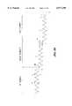
- FIG. 3is a plan view of a formed wire useful for rolling about an axis into a multi-segment support structure in accordance with the present invention.
- FIG. 4is an enlarged detail view of a portion of the formed wire illustrated in FIG. 3.
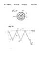
- FIG. 5is a cross sectional view taken along the lines 5--5 of FIG. 4.
- FIG. 6is an alternate cross sectional view taken along the lines 5--5 of FIG. 4.
- FIG. 7is a fragmentary view of an alternate wire layout in accordance with a further aspect of the present invention.
- FIG. 8is an elevational view of a crosslinked wire layout in accordance with the present invention.
- FIG. 8Ais a plan view of a formed wire layout useful for forming the crosslinked embodiment of FIG. 8.
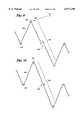
- FIG. 9is a fragmentary view of an alternate wire layout in accordance with a further aspect of the present invention.
- FIG. 10is a fragmentary view of an alternate wire layout in accordance with a further aspect of the present invention.
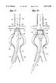
- FIG. 11is a fragmentary view of an apex in accordance with one aspect of the present invention.
- FIG. 12is a fragmentary view of an alternate embodiment of an apex in accordance with the present invention.
- FIG. 13is a further embodiment of an apex in accordance with the present invention.
- FIG. 14is a fragmentary view of a further wire layout in accordance with the present invention.
- FIG. 15is a fragmentary view of a further wire layout in accordance with the present invention.
- FIG. 16is a fragmentary view of a further wire layout in accordance with the present invention.
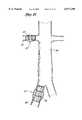
- FIG. 17is a schematic illustration of a delivery catheter in accordance with the present invention, positioned within an abdominal aortic aneurysm.
- FIG. 18is an illustration as in FIG. 17, with the endoluminal prosthesis partially deployed from the delivery catheter.
- FIG. 19is a cross sectional view taken along the lines 19--19 of FIG. 17.
- FIG. 20is a detailed fragmentary view of a tapered wire embodiment in accordance with a further aspect of the present invention.
- FIG. 21is a schematic representation of the abdominal aortic anatomy, with an endoluminal vascular prosthesis of the present invention positioned within each of the right renal artery and the right common iliac.
- FIG. 22is a further embodiment in accordance with the present invention.
- FIG. 1there is disclosed a schematic representation of the abdominal part of the aorta and its principal branches.
- the abdominal aorta 30is characterized by a right renal artery 32 and left renal artery 34.
- the large terminal branches of the aortaare the right and left common iliac arteries 36 and 38.
- Additional vesselse.g., second lumbar, testicular, inferior mesenteric, middle sacral
- a generally symmetrical aneurysm 40is illustrated in the infrarenal portion of the diseased aorta.
- An expanded endoluminal vascular prosthesis 42in accordance with the present invention, is illustrated spanning the aneurysm 40.
- endoluminal vascular prosthesis of the present inventioncan be modified for use in a bifurcation aneurysm, such as the common iliac bifurcation, the endoluminal prosthesis of the present invention will be described herein primarily in terms of its application in the straight segment of the abdominal aorta, or Thoracic or iliac arteries.
- the endoluminal vascular prosthesis 42includes a polymeric sleeve 44 and a tubular wire support 46, which are illustrated in situ in FIG. 1.
- the sleeve 44 and wire support 46are more readily visualized in the exploded view shown in FIG. 2.
- the endoluminal prosthesis 42 illustrated and described hereindepicts an embodiment in which the polymeric sleeve 44 is situated concentrically outside of the tubular wire support 46.
- other embodimentsmay include a sleeve situated instead concentrically inside the wire support or on both of the inside and the outside of the wire support.
- the wire supportmay be embedded within a polymeric matrix which makes up the sleeve.
- the sleeve 44may be attached to the wire support by any of a variety of means, including laser bonding, adhesives, clips, sutures, dipping or spraying or others, depending upon the composition of the sleeve 44 and overall graft design.
- the polymeric sleeve 44may be formed from any of a variety of synthetic polymeric materials, or combinations thereof, including PTFE, PE, PET, Urethane, Dacron, nylon, polyester or woven textiles.
- the sleeve materialexhibits relatively low inherent elasticity, or low elasticity out to the intended enlarged diameter of the wire cage 46.
- the sleeve materialpreferably has a thin profile, such as no larger than about 0.002 inches to about 0.005 inches.
- the material of sleeve 44is sufficiently porous to permit ingrowth of endothelial cells, thereby providing more secure anchorage of the prosthesis and potentially reducing flow resistance, sheer forces, and leakage of blood around the prosthesis.
- Porosity in polymeric sleeve materialsmay be estimated by measuring water permeability as a function of hydrostatic pressure, which will preferably range from about 3 to 6 psi.
- the porosity characteristics of the polymeric sleeve 44may be either homogeneous throughout the axial length of the prosthesis 42, or may vary according to the axial position along the prosthesis 42. For example, referring to FIGS. 1 and 2, different physical properties will be called upon at different axial positions along the prosthesis 42 in use. At least a proximal portion 55 and a distal portion 59 of the prosthesis 42 will seat against the native vessel wall, proximally and distally of the aneurysm. In these proximal and distal portions, the prosthesis preferably encourages endothelial growth, or, at least, permits endothelial growth to infiltrate portions of the prosthesis in order to enhance anchoring and minimize leakage.
- a central portion 57 of the prosthesisspans the aneurysm, and anchoring is less of an issue. Instead, minimizing blood flow through the prosthesis wall becomes a primary objective.
- the polymeric sleeve 44may either be nonporous, or provided with pores of no greater than about 60% to 80%.
- a multi-zoned prosthesis 42may also be provided in accordance with the present invention by positioning a tubular sleeve 44 on a central portion 57 of the prosthesis, such that it spans the aneurysm to be treated, but leaving a proximal attachment zone 55 and a distal attachment zone 59 of the prosthesis 42 having exposed wires from the wire support 46.
- the exposed wires 46are positioned in contact with the vessel wall both proximally and distally of the aneurysm, such that the wire, over time, becomes embedded in cell growth on the interior surface of the vessel wall.
- the sleeve 44 and/or the wire support 46is tapered, having a relatively larger expanded diameter at the proximal end 50 compared to the distal end 52.
- the tapered designmay allow the prosthesis to conform better to the natural decreasing distal cross section of the vessel, to reduce the risk of graft migration and potentially create better flow dynamics.
- the tubular wire support 46is preferably formed from a continuous single length of round (shown in FIG. 5) or flattened (shown in FIG. 6) wire.
- the wire support 46is preferably formed in a plurality of discrete segments 54, connected together and oriented about a common axis. Each pair of adjacent segments 54 is connected by a connector 66 as will be discussed.
- the connectors 66collectively produce a generally axially extending backbone which adds axial strength to the prosthesis 42.
- Adjacent segmentscan be connected both by the backbone, as well as by other structures, including circumferentially extending sutures 56 (illustrated in FIGS. 1 and 2), solder joints, wire loops and any of a variety of interlocking relationships.
- the suturecan be made from any of a variety of biocompatible polymeric materials or alloys, such as nylon, polypropylene, or stainless steel. Other means of securing the segments 54 to one another are discussed below (see FIG. 8).
- Each segment 54though joined to adjacent segments, may be independently engineered to yield desired parameters. Each segment may range in axial length from about 0.3 to about 5 cm. Generally, the shorter their length the greater the radial strength.
- An endoluminal prosthesismay include from about 1 to about 50 segments, preferably from about 3 to about 10 segments.
- a short graft patchin accordance with the invention, may comprise only 2 segments and span a total of 2 to 3 cm, a complete graft may comprise 4 or more segments and span the entire aortic aneurysm.
- further flexibilitycan be achieved through adjustments in the number, angle, or configuration of the wire bends associated with the tubular support. Potential bend configurations are discussed in greater detail below (see FIGS. 4-16).
- the wire cage 46is dividable into a proximal zone 55, a central zone 57 and a distal zone 59.
- the wire cage 46can be configured to taper from a relatively larger diameter in the proximal zone 55 to a relatively smaller diameter in the distal zone 59.
- the wire cage 46can have a transitional tapered and or stepped diameter within a given zone.
- the cage 46can also be provided with a proximal zone 55 and distal zone 59 that have a larger relative expanded diameter than the central zone 57, as illustrated in FIG. 2. This configuration may desirably resist migration of the prosthesis within the vessel.
- the proximal zone 55 and/or distal zone 59can be left without an outer covering 44, with the outer sleeve 44 covering only the central zone 57. This permits the proximal and distal zones 55, 59 to be in direct contact with tissue proximally and distal to the lesion, which may facilitate endothelial cell growth.
- different zonescan be provided with a different radial expansion force, such as ranging from about 0.2 lbs to about 0.8 lbs.
- the proximal zone 55is provided with a greater radial force than the central zone 57 and/or distal zone 59.
- the greater radial forcecan be provided in any of a variety of manners discussed elsewhere herein, such as through the use of an additional one or two or three or more proximal bends 60, distal bends 62 and wall sections 64 compared to a reference segment 54 in the central zone 57 or distal zone 59.
- proximal zone 55can be achieved through the use of the same number of proximal bends 60 as in the rest of the prosthesis, but with a heavier gauge wire.
- Radial force beyond the expanded diameter limit of the central zone 57can be achieved by tightening the suture 56 as illustrated in FIG. 2 such that the central zone 57 is retained under compression even in the expanded configuration.
- the proximal end and distal endwill flair radially outwardly to a fully expanded configuration as illustrated in FIG. 2.
- the wiremay be made from any of a variety of different alloys, such as elgiloy, nitinol or MP35N, or other alloys which include nickel, titanium, tantalum, or stainless steel, high Co--Cr alloys or other temperature sensitive materials.
- elgiloy, nitinol or MP35Nor other alloys which include nickel, titanium, tantalum, or stainless steel, high Co--Cr alloys or other temperature sensitive materials.
- an alloycomprising Ni 15%, Co 40%, Cr 20%, Mo 7% and balance Fe may be used.
- the tensile strength of suitable wireis generally above about 300 K psi and often between about 300 and about 340 K psi for many embodiments.
- a Chromium-Nickel-Molybdenum alloysuch as that marketed under the name Conichrom (Fort Wayne Metals, Ind.) has a tensile strength ranging from 300 to 320 K psi, elongation of 3.5-4.0% and breaking load at approximately 80 lbs to 70 lbs.
- the wiremay be treated with a plasma coating and be provided with/without coating such as: PTFE, Teflon, Perlyne and Drugs.
- radial strengthmeasured at 50% of the collapsed profile, preferably ranges from about 0.2 lb to 0.8 lb, and generally from about 0.4 lb to about 0.5 lb. or more.
- Preferred wire diameters in accordance with the present inventionrange from about 0.004 inches to about 0.020 inches. More preferably, the wire diameters range from about 0.006 inches to about 0.018 inches. In general, the greater the wire diameter, the greater the radial strength for a given wire layout.
- the wire gaugecan be varied depending upon the application of the finished graft, in combination with/or separate from variation in other design parameters (such as the number of struts, or proximal bends 60 and distal bends 62 per segment), as will be discussed.
- a wire diameter of approximately 0.018 inchesmay be useful in a graft having four segments each having 2.5 cm length per segment, each segment having six struts intended for use in the aorta, while a smaller diameter such as 0.006 inches might be useful for a 0.5 cm segment graft having 5 struts per segment intended for the iliac artery.
- the length of cage 42could be as long as about 28 cm.
- the wire diameteris tapered from the proximal to distal ends.
- the wire diametermay be tapered incrementally or stepped down, or stepped up, depending on the radial strength requirements of each particular clinical application.
- the wirehas a cross section of about 0.018 inches in the proximal zone 55 and the wire tapers down to a diameter of about 0.006 inches in the distal zone 59 of the graft 42. End point dimensions and rates of taper can be varied widely, within the spirit of the present invention, depending upon the desired clinical performance.
- FIG. 3there is illustrated a plan view of the single formed wire used for rolling about a longitudinal axis to produce a four segment tubular wire support.
- the formed wireexhibits distinct segments, each corresponding to an individual tubular segment 54 in the tubular support (see FIGS. 1 and 2).
- Each segmenthas a repeating pattern of proximal bends 60 connected to corresponding distal bends 62 by wall sections 64 which extend in a generally zig zag configuration when the segment 54 is radially expanded.
- Each segment 54is connected to the adjacent segment 54 through a connector 66, except at the terminal ends of the graft.
- the connector 66 in the illustrated embodimentcomprises two wall sections 64 which connect a proximal bend 60 on a first segment 54 with a distal bend 62 on a second, adjacent segment 54.
- the connector 66may additionally be provided with a connector bend 68, which may be used to impart increased radial strength to the graft and/or provide a tie site for a circumferentially extending suture.
- a proximal bend 60comprises about a 180 degree arc, having a radial diameter of (w) (Ranging from 0.070 to 0.009 inches), depending on wire diameter followed by a relatively short length of parallel wire spanning an axial distance of d1.
- the parallel wiresthereafter diverge outwardly from one another and form the strut sections 64, or the proximal half of a connector 66.
- the wireforms a distal bend 62, preferably having identical characteristics as the proximal bend 60, except being concave in the opposite direction.
- the axial direction component of the distance between the apices of the corresponding proximal and distal bends 60, 62is referred to as (d) and represents the axial length of that segment.
- the total expanded angle defined by the bend 60 and the divergent strut sections 64is represented by ⁇ .
- ⁇is generally within the range of from about 35° to about 45°.
- the expanded circumferential distance between any two adjacent distal bends 62 (or proximal bends 60)is defined as (s).
- the diameter W of each proximal bend 60 or distal bend 62is within the range of from about 0.009 inches to about 0.070 inches depending upon the wire diameter.
- Diameter Wis preferably as small as possible for a given wire diameter and wire characteristics. As will be appreciated by those of skill in the art, as the distance W is reduced to approach two times the cross section of the wire, the bend 60 or 62 will exceed the elastic limit of the wire, and radial strength of the finished segment will be lost. Determination of a minimum value for W, in the context of a particular wire diameter and wire material, can be readily determined through routine experimentation by those of skill in the art.
- the distance d1is preferably minimized within the desired radial strength performance requirements. As d1 increases, it may disadvantageously increase the collapsed profile of the graft.
- the sum of the distances (s) in a plane transverse to the longitudinal axis of the finished graftwill correspond to the circumference of the finished graft in that plane.
- the number of proximal bends 60 or distal bends 62is directly related to the distance (s) in the corresponding plane.
- the finished graft in any single transverse planewill have from about 3 to about 10 (s) dimensions, preferably from about 4 to about 8 (s) dimensions and, more preferably, about 5 or 6 (s) dimensions for an aortic application.
- Each (s) dimensioncorresponds to the distance between any two adjacent bends 60-60 or 62-62 as will be apparent from the discussion herein.
- Each segment 54can thus be visualized as a series of triangles extending circumferentially around the axis of the graft, defined by a proximal bend 60 and two distal bends 62 or the reverse.
- wire support parameterssuch as d, d1, s, alpha and alpha'
- the manufacturerenjoys tremendous design control with respect to the total axial length, axial and radial flexibility, radial force and expansion ratios, and consequently prosthesis performance.
- an increase in the dimension (w)translates directly into an increased collapsed profile since the circumference of the collapsed profile can be no smaller than the sum of the distances (w) in a given transverse plane.
- an increase in the number of proximal bends 60 in a given segmentmay increase radial strength, but will similarly increase the collapsed profile.
- the wall sections 64act as a lever arm for translating that force into radial strength.
- decreasing the length of strut sections 64 for a given number of proximal bends 60will increase the radial strength of the segment but call for additional segments to maintain overall graft length.
- radial strengthis best accomplished by decreasing the length of wall sections 64 rather than increasing the number of proximal bends 60.
- increasing the number of (shorter) segments 54 in a given overall length graftwill increase the degree of axial shortening upon radial expansion of the graft.
- increased radial strengthmay be optimized through selection of wire material or wire gauge and other parameters, while minimizing the number of total segments in the graft.
- Other geometry consequences of the present inventionwill be apparent to those of skill in the art in view of the disclosure herein.
- wis about 2.0 mm ⁇ 1 mm for a 0.018 inch wire diameter.
- D1is about 3 mm ⁇ 1 mm
- dis about 20 mm ⁇ 1 mm
- cis about 23 mm ⁇ 1 mm
- gis about 17 mm
- ⁇ 1 mmis about 3 mm ⁇ 1 mm
- bis about 3 mm ⁇ 1 mm.
- Specific dimensions for all of the foregoing variablescan be varied considerably, depending upon the desired wire configuration, in view of the disclosure herein.
- FIG. 7there is shown an alternative wire layout having a plurality of radiussed bends 70 in one or more sections of strut 64 which may be included to provide additional flex points to provide enhanced fluid dynamic characteristics and maintain the tubular shape.
- each pair of adjacent proximal and distal segments, 76 and 78may be joined by crosslinking of the corresponding proximal and distal bends.
- a proximal bend 60 from a distal segment 78is connected to the corresponding distal bend 62 of a proximal segment 76, thereby coupling the proximal segment 76 and distal segment 78.
- the connection between corresponding proximal bends 60 and distal bends 62can be accomplished in any of a variety of ways as will be apparent to those of skill in the art in view of the disclosure herein. In the illustrated embodiment, the connection is accomplished through the use of a link 72.
- Link 72may be a loop of metal such as stainless steel, a suture, a welded joint or other type of connection.
- link 72comprises a metal loop or ring which permits pivotable movement of a proximal segment 76 with respect to a distal segment 78.
- the proximal segment 76is provided with six distal bends 62.
- the corresponding distal segment 78is provided with six proximal bends 60 such that a one to one correspondence exists.
- a link 72may be provided at each pair of corresponding bends 60, 62, such that six links 72 exist in a plane transverse to the longitudinal axis of the graft at the interface between the proximal segment 76 and the distal segment 78.
- links 72can be provided at less than all of the corresponding bends, such as at every other bend, every third bend, or only on opposing sides of the graft.
- the distribution of the links 72 in any given embodimentcan be selected to optimize the desired flexibility characteristics and other performance criteria in a given design.
- connectorssuch as cross link 72 enables improved tracking of the graft around curved sections of the vessel.
- the wire cage 46 as illustrated in FIG. 8can be bent around a gentle curve, such that it will both retain the curved configuration and retain patency of the central lumen extending axially therethrough.
- the embodiment illustrated in FIG. 2may be more difficult to track curved anatomy while maintaining full patency of the central lumen.
- the ability to maintain full patency while extending around a curvemay be desirable in certain anatomies, such as where the aorta fails to follow the linear infrarenal path illustrated in FIG. 1.
- FIG. 8athere is illustrated a plan view of a formed wire useful for rolling about an axis to produce a multi-segmented support structure of the type illustrated in FIG. 8.
- the formed wire of FIG. 8ais similar to that illustrated in FIG. 3.
- any given pair of corresponding distal bends 62 and proximal bends 60 of the embodiment of FIG. 3overlap in the axial direction to facilitate threading a circumferential suture therethrough
- the corresponding distal bend 62 and proximal bend 60 of the embodiment illustrated in FIG. 8amay abut end to end against each other or near each other as illustrated in FIG. 8 to receive a connector 72 thereon.
- a distal bend 62 with respect to a corresponding proximal bend 60can be accomplished in a variety of ways, most conveniently by appropriate formation of the connector bend 68 between adjacent segments of the wire cage.
- FIGS. 9-16illustrate alternative bend configurations in accordance with the present invention.
- FIG. 9shows one embodiment having the proximal and distal bends as eyelets, but the connector bend 68, remaining in the usual configuration.
- the embodiment illustrated in FIG. 10has the proximal and distal bends as well as the connector bend in the eyelet configuration.
- Various eyelet designs in accordance with the present inventionare shown in greater detail in FIGS. 11-13, including a double-looped circular eyelet (FIG. 11), a double-looped triangular eyelet (FIG. 12), and a single-looped triangular eyelet (FIG. 13).
- the eyeletscan be used to receive a circumferentially extending suture or wire as has been described.
- FIGS. 14-16Additional embodiments of the wire configuration are illustrated in FIGS. 14-16.
- FIG. 14shows an embodiment of the proximal 60 and distal 62 bends in which double bends are employed to increase the flexion.
- FIG. 15shows triangular bends having a more pronounced length (d1) of parallel wire, and accordingly shorter wall sections 64.
- FIG. 16shows another embodiment of the proximal and distal bends in FIG. 16, wherein the triangular bends include additional flexion points in the form of wall segment bends 70.
- a delivery catheter 80having a dilator tip 82, is advanced along guidewire 84 until the (anatomically) proximal end 50 of the collapsed endoluminal vascular prosthesis 86 is positioned between the renal arteries 32 and 34 and the aneurysm 40.
- the collapsed prosthesis in accordance with the present inventionhas a diameter in the range of about 2 to about 10 mm.
- the diameter of the collapsed prosthesisis in the range of about 3 to 6 mm (12 to 18 French). More preferably, the delivery catheter including the prosthesis will be 16 F, or 15 F or 14 F or smaller.
- the prosthesis 86is maintained in its collapsed configuration by the restraining walls of the tubular delivery catheter 80, such that removal of this restraint would allow the prosthesis to self expand.
- Radiopaque marker materialmay be incorporated into the delivery catheter 80, and/or the prosthesis 86, at least at both the proximal and distal ends, to facilitate monitoring of prosthesis position.
- the dilator tip 82is bonded to an internal catheter core 92, as illustrated in FIG. 18, wherein the internal catheter core 92 and the partially expanded prosthesis 88 are revealed as the outer sheath of the delivery catheter 80 is retracted.
- the internal catheter core 92is also depicted in the cross-sectional view in FIG. 19.
- the collapsed prosthesis 86remains substantially fixed axially relative to the internal catheter core 92 and consequently, self-expands at a predetermined vascular site as illustrated in FIG. 18.
- the expanded endoluminal vascular prosthesishas radially self-expanded to a diameter anywhere in the range of about 20 to 40 mm, corresponding to expansion ratios of about 1:2 to 1:20.
- the expansion ratiosrange from about 1:4 to 1:8, more preferably from about 1:4 to 1:6.
- the prosthesis 86may be maintained in its collapsed configuration by a restraining lace, which may be woven through the prosthesis or wrapped around the outside of the prosthesis in the collapsed reduced diameter. Following placement of the prosthesis at the treatment site, the lace can be proximally retracted from the prosthesis thereby releasing it to self expand at the treatment site.
- the lacemay comprise any of a variety of materials, such as sutures, strips of PTFE, FEP, polyester fiber, and others as will be apparent to those of skill in the art in view of the disclosure herein.
- the restraining lacemay extend proximally through a lumen in the delivery catheter or outside of the catheter to a proximal control.
- the controlmay be a pull tab or ring, rotatable reel, slider switch or other structure for permitting proximal retraction of the lace.
- the lacemay extend continuously throughout the length of the catheter, or may be joined to another axially moveable element such as a pull wire.
- the expanded diameter of the graft in accordance with the present inventioncan be any diameter useful for the intended lumen or hollow organ in which the graft is to be deployed.
- the expanded sizewill be within the range of from about 10 to about 40 mm.
- Abdominal aortic applicationswill generally require a graft having an expanded diameter within the range of from about 20 to about 28 mm, and, for example, a graft on the order of about 45 mm may be useful in the thoracic artery.
- the foregoing dimensionsrefer to the expanded size of the graft in an unconstrained configuration, such as on the table.
- the graftwill be positioned within an artery having a slightly smaller interior cross section than the expanded size of the graft. This enables the graft to maintain a slight positive pressure against the wall of the artery, to assist in retention of the graft during the period of time prior to endothelialization of the polymeric sleeve 44.
- radial force exerted by the proximal segment 94 of the prosthesis against the walls of the aorta 30provides a seal against the leakage of blood around the vascular prosthesis and tends to prevent axial migration of the deployed prosthesis.
- this radial forcecan be modified as required through manipulation of various design parameters, including the axial length of the segment and the bend configurations.
- radial tensioncan be enhanced at the proximal, upstream end by changes in the wire gauge as illustrated in FIG. 20. Note that the wire gauge increases progressively along the wall segments 64 from T1 at the proximal bends 60 to T2 at the distal bends 62.
- T1may range from about 0.001 to 0.01 inches whereas T2 may range from about 0.01 to 0.03 inches.
- An alternative embodiment of the wire layout which would cause the radial tension to progressively decrease from the proximal segments to the distal segmentsinvolves a progressive or step-wise decrease in the wire gauge throughout the entire wire support, from about 0.01 to 0.03 inches at the proximal end to about 0.002 to 0.01 inches at the distal end.
- Such an embodimentmay be used to create a tapered prosthesis.
- the wire gaugemay be thicker at both the proximal and distal ends, in order to insure greater radial tension and thus, sealing capacity.
- the wire gauge in the proximal and distal segmentsmay about 0.01 to 0.03 inches, whereas the intervening segments may be constructed of thinner wire, in the range of about 0.001 to 0.01 inches.
- FIG. 21there is illustrated two alternative deployment sites for the endoluminal vascular prosthesis 42 of the present invention.
- a symmetrical aneurysm 33is illustrated in the right renal artery 32.
- An expanded endoluminal vascular prosthesis 42in accordance with the present invention, is illustrated spanning that aneurysm 33.
- an aneurysm of the right common iliac 37is shown, with a prosthesis 42 deployed to span the iliac aneurysm 37.
- the endovascular prosthesis 96is provided with a wire cage 46 having six axially aligned segments 54. As with the previous embodiments, however, the endovascular prosthesis 96 may be provided with anywhere from about 2 to about 10 or more axially spaced or adjacent segments 54, depending upon the clinical performance objectives of the particular embodiment.
- the wire support 46is provided with a tubular polymeric sleeve 44 as has been discussed. In the present embodiment, however, one or more lateral perfusion ports or openings are provided in the polymeric sleeve 44, such as a right renal artery perfusion port 98 and a left renal artery perfusion port 100 as illustrated.
- Perfusion ports in the polymeric sleeve 44may be desirable in embodiments of the endovascular prosthesis 96 in a variety of clinical contexts.
- FIGS. 1 and 22illustrate a generally symmetrical aneurysm 40 positioned within a linear infrarenal portion of the abdominal aorta, spaced axially apart both from bilaterally symmetrical right and left renal arteries and bilaterally symmetrical right and left common iliacs
- both the position and symmetry of the aneurysm 40 as well as the layout of the abdominal aortic architecturemay differ significantly from patient to patient.
- the endovascular prosthesis 96may need to extend across one or both of the renal arteries in order to adequately anchor the endovascular prosthesis 96 and/or span the aneurysm 40.
- the provision of one or more lateral perfusion portsenables the endovascular prosthesis 96 to span the renal arteries while permitting perfusion therethrough, thereby preventing "stent jailing" of the renals.
- Lateral perfusion through the endovascular prosthesis 96may also be provided, if desired, for a variety of other arteries including the second lumbar, testicular, inferior mesenteric, middle sacral, and alike as will be well understood to those of skill in the art.
- the endovascular prosthesis 96is preferably provided with at least one, and preferably two or more radiopaque markers, to facilitate proper positioning of the prosthesis 96 within the artery.
- the prosthesis 96should be properly aligned both axially and rotationally, thereby requiring the ability to visualize both the axial and rotational position of the device.
- the rotational orientation of the graftmaybe coordinated with an indexed marker on the proximal end of the catheter, so that the catheter may be rotated and determined by an external indicium of rotational orientation to be appropriately aligned with the right and left renal arteries.
- the polymeric sleeve 44extends across the aneurysm 40, but terminates in the infrarenal zone.
- a proximal zone 55 on the prosthesis 96comprises a wire cage 46 but no polymeric sleeve 44.
- the prosthesis 96still accomplishes the anchoring function across the renal arteries, yet does not materially interfere with renal perfusion.
- the polymeric sleeve 44may cover anywhere from about 50% to about 100% of the axial length of the prosthesis 96 depending upon the desired length of uncovered wire cage 46 such as for anchoring and/or lateral perfusion purposes.
- the polymeric sleeve 44may cover within the range of from about 70% to about 80%, and, in one four segment embodiment having a single exposed segment, 75%, of the overall length of the prosthesis 96.
- the uncovered wire cage 46may reside at only a single end of the prosthesis 96, such as for traversing the renal arteries. Alternatively, exposed portions of the wire cage 46 may be provided at both ends of the prosthesis such as for anchoring purposes.
- a two part polymeric sleeve 44is provided.
- a first distal partspans the aneurysm 40, and has a proximal end which terminates distally of the renal arteries.
- a second, proximal part of the polymeric sleeve 44is carried by the proximal portion of the wire cage 46 which is positioned superiorly of the renal arteries. This leaves an annular lateral flow path through the side wall of the vascular prosthesis 96, which can be axially aligned with the renal arteries, without regard to rotational orientation.
- the axial length of the gap between the proximal and distal segments of polymeric sleeve 44can be adjusted, depending upon the anticipated cross sectional size of the ostium of the renal artery, as well as the potential axial misalignment between the right and left renal arteries.
- the right renal artery 32 and left renal artery 34are illustrated in FIG. 22 as being concentrically disposed on opposite sides of the abdominal aorta, the take off point for the right or left renal arteries from the abdominal aorta may be spaced apart along the abdominal aorta as will be familiar to those of skill in the art.
- the diameter of the ostium of the renal artery measured in the axial direction along the abdominal aortafalls within the range of from about 7 cm to about 20 cm for a typical adult patient.
- Clinical and design challengeswhich are satisfied by the present invention, include providing a sufficient seal between the upstream end of the vascular prosthesis and the arterial wall, providing a sufficient length to span the abdominal aortic aneurysm, providing sufficient wall strength or support across the span of the aneurysm, and providing a sufficient expansion ratio, such that a minimal percutaneous axis diameter may be utilized for introduction of the vascular prosthesis in its collapsed configuration.
- Embodiments of the present inventioncan be constructed having a 16 French or 15 French or 14 French or smaller profile (e.g. 3-4 mm) thereby enabling placement of the endoluminal vascular prosthesis of the present invention by way of a percutaneous procedure.
- the endoluminal vascular prosthesis of the present inventiondoes not require a post implantation balloon dilatation, can be constructed to have minimal axial shrinkage upon radial expansion, and avoids the disadvantages associated with nitinol grafts.
Landscapes
- Health & Medical Sciences (AREA)
- Engineering & Computer Science (AREA)
- Biomedical Technology (AREA)
- Heart & Thoracic Surgery (AREA)
- Public Health (AREA)
- Transplantation (AREA)
- Cardiology (AREA)
- Veterinary Medicine (AREA)
- Oral & Maxillofacial Surgery (AREA)
- Vascular Medicine (AREA)
- Life Sciences & Earth Sciences (AREA)
- Animal Behavior & Ethology (AREA)
- General Health & Medical Sciences (AREA)
- Gastroenterology & Hepatology (AREA)
- Pulmonology (AREA)
- Prostheses (AREA)
- Materials For Medical Uses (AREA)
Abstract
Description
Claims (38)
Priority Applications (15)
| Application Number | Priority Date | Filing Date | Title |
|---|---|---|---|
| US09/034,689US6077296A (en) | 1998-03-04 | 1998-03-04 | Endoluminal vascular prosthesis |
| PCT/US1998/012114WO1999044536A1 (en) | 1998-03-04 | 1998-06-15 | Endoluminal vascular prosthesis |
| AU79600/98AAU7960098A (en) | 1998-03-04 | 1998-06-15 | Endoluminal vascular prosthesis |
| RU2000123558/14ARU2207826C2 (en) | 1998-03-04 | 1998-06-15 | Vascular prosthesis having internal lumen |
| CN98813843ACN1301139A (en) | 1998-03-04 | 1998-06-15 | Endoluminal vascular prosthesis |
| JP2000534144AJP4143749B2 (en) | 1998-03-04 | 1998-06-15 | Intraluminal artificial blood vessels |
| KR1020007009800AKR20010041603A (en) | 1998-03-04 | 1998-06-15 | Endoluminal Vascular Prosthesis |
| AT98930137TATE304330T1 (en) | 1998-03-04 | 1998-06-15 | PROSTHESIS INSIDE A VESSEL |
| DE69831608TDE69831608T2 (en) | 1998-03-04 | 1998-06-15 | PROSTHESIS IN THE INSIDE OF A VESSEL |
| EP98930137AEP1059893B1 (en) | 1998-03-04 | 1998-06-15 | Endoluminal vascular prosthesis |
| US09/483,411US6331190B1 (en) | 1998-03-04 | 2000-01-14 | Endoluminal vascular prosthesis |
| US10/032,230US20020147492A1 (en) | 1998-03-04 | 2001-12-18 | Endoluminal vascular prosthesis |
| US10/755,703US20040204753A1 (en) | 1998-03-04 | 2004-01-12 | Endoluminal vascular prosthesis |
| US11/417,651US20060271163A1 (en) | 1998-03-04 | 2006-05-03 | Endoluminal vascular prosthesis |
| US11/623,679US20070112412A1 (en) | 1998-03-04 | 2007-01-16 | Endoluminal vascular prosthesis |
Applications Claiming Priority (1)
| Application Number | Priority Date | Filing Date | Title |
|---|---|---|---|
| US09/034,689US6077296A (en) | 1998-03-04 | 1998-03-04 | Endoluminal vascular prosthesis |
Related Child Applications (1)
| Application Number | Title | Priority Date | Filing Date |
|---|---|---|---|
| US09/483,411ContinuationUS6331190B1 (en) | 1998-03-04 | 2000-01-14 | Endoluminal vascular prosthesis |
Publications (1)
| Publication Number | Publication Date |
|---|---|
| US6077296Atrue US6077296A (en) | 2000-06-20 |
Family
ID=21877986
Family Applications (6)
| Application Number | Title | Priority Date | Filing Date |
|---|---|---|---|
| US09/034,689Expired - LifetimeUS6077296A (en) | 1998-03-04 | 1998-03-04 | Endoluminal vascular prosthesis |
| US09/483,411Expired - Fee RelatedUS6331190B1 (en) | 1998-03-04 | 2000-01-14 | Endoluminal vascular prosthesis |
| US10/032,230AbandonedUS20020147492A1 (en) | 1998-03-04 | 2001-12-18 | Endoluminal vascular prosthesis |
| US10/755,703AbandonedUS20040204753A1 (en) | 1998-03-04 | 2004-01-12 | Endoluminal vascular prosthesis |
| US11/417,651AbandonedUS20060271163A1 (en) | 1998-03-04 | 2006-05-03 | Endoluminal vascular prosthesis |
| US11/623,679AbandonedUS20070112412A1 (en) | 1998-03-04 | 2007-01-16 | Endoluminal vascular prosthesis |
Family Applications After (5)
| Application Number | Title | Priority Date | Filing Date |
|---|---|---|---|
| US09/483,411Expired - Fee RelatedUS6331190B1 (en) | 1998-03-04 | 2000-01-14 | Endoluminal vascular prosthesis |
| US10/032,230AbandonedUS20020147492A1 (en) | 1998-03-04 | 2001-12-18 | Endoluminal vascular prosthesis |
| US10/755,703AbandonedUS20040204753A1 (en) | 1998-03-04 | 2004-01-12 | Endoluminal vascular prosthesis |
| US11/417,651AbandonedUS20060271163A1 (en) | 1998-03-04 | 2006-05-03 | Endoluminal vascular prosthesis |
| US11/623,679AbandonedUS20070112412A1 (en) | 1998-03-04 | 2007-01-16 | Endoluminal vascular prosthesis |
Country Status (10)
| Country | Link |
|---|---|
| US (6) | US6077296A (en) |
| EP (1) | EP1059893B1 (en) |
| JP (1) | JP4143749B2 (en) |
| KR (1) | KR20010041603A (en) |
| CN (1) | CN1301139A (en) |
| AT (1) | ATE304330T1 (en) |
| AU (1) | AU7960098A (en) |
| DE (1) | DE69831608T2 (en) |
| RU (1) | RU2207826C2 (en) |
| WO (1) | WO1999044536A1 (en) |
Cited By (133)
| Publication number | Priority date | Publication date | Assignee | Title |
|---|---|---|---|---|
| US6190405B1 (en)* | 1997-05-28 | 2001-02-20 | Gfe Corporation For Research And Development Unlimited | Flexible expandable vascular support |
| US6331190B1 (en)* | 1998-03-04 | 2001-12-18 | Endologix, Inc. | Endoluminal vascular prosthesis |
| WO2002060352A1 (en)* | 2001-01-30 | 2002-08-08 | Ev3 Santa Rosa, Inc. | Medical system and method for remodeling an extravascular tissue structure |
| US6436132B1 (en)* | 2000-03-30 | 2002-08-20 | Advanced Cardiovascular Systems, Inc. | Composite intraluminal prostheses |
| US20020138129A1 (en)* | 1999-01-22 | 2002-09-26 | Armstrong Joseph R. | Method of producing low profile stent and graft combination |
| US20020165602A1 (en)* | 1998-06-19 | 2002-11-07 | Douglas Myles S. | Self expanding bifurcated endovascular prosthesis |
| US6500202B1 (en) | 1998-12-11 | 2002-12-31 | Endologix, Inc. | Bifurcation graft deployment catheter |
| US6508835B1 (en) | 1998-12-11 | 2003-01-21 | Endologix, Inc. | Endoluminal vascular prosthesis |
| US6524335B1 (en)* | 1997-12-10 | 2003-02-25 | William A. Cook Australia Pty. Ltd. | Endoluminal aortic stents |
| US6537314B2 (en)* | 2000-01-31 | 2003-03-25 | Ev3 Santa Rosa, Inc. | Percutaneous mitral annuloplasty and cardiac reinforcement |
| US20030135267A1 (en)* | 2002-01-11 | 2003-07-17 | Solem Jan Otto | Delayed memory device |
| US6641607B1 (en) | 2000-12-29 | 2003-11-04 | Advanced Cardiovascular Systems, Inc. | Double tube stent |
| US6652574B1 (en)* | 2000-09-28 | 2003-11-25 | Vascular Concepts Holdings Limited | Product and process for manufacturing a wire stent coated with a biocompatible fluoropolymer |
| US6660030B2 (en) | 1998-12-11 | 2003-12-09 | Endologix, Inc. | Bifurcation graft deployment catheter |
| US6663665B2 (en) | 1999-03-11 | 2003-12-16 | Endologix, Inc. | Single puncture bifurcation graft deployment system |
| US6733523B2 (en) | 1998-12-11 | 2004-05-11 | Endologix, Inc. | Implantable vascular graft |
| US20040102840A1 (en)* | 1999-06-30 | 2004-05-27 | Solem Jan Otto | Method and device for treatment of mitral insufficiency |
| US20040133220A1 (en)* | 2000-01-31 | 2004-07-08 | Randall Lashinski | Adjustable transluminal annuloplasty system |
| US20040193254A1 (en)* | 2003-01-14 | 2004-09-30 | Greenberg Roy K. | Branched vessel endoluminal device |
| US6805706B2 (en) | 2002-08-15 | 2004-10-19 | Gmp Cardiac Care, Inc. | Stent-graft with rails |
| WO2004091449A1 (en)* | 2003-04-08 | 2004-10-28 | Cook Incorporated | Intraluminal support device with graft |
| US6810882B2 (en) | 2001-01-30 | 2004-11-02 | Ev3 Santa Rosa, Inc. | Transluminal mitral annuloplasty |
| US20050021136A1 (en)* | 2002-03-21 | 2005-01-27 | Hua Xie | Method for suturelessly attaching a biomaterial to an implantable bioprosthesis frame |
| US20050043792A1 (en)* | 1999-06-29 | 2005-02-24 | Edwards Lifesciences Ag | Device and method for treatment of mitral insufficiency |
| US20050049480A1 (en)* | 2003-08-25 | 2005-03-03 | Biophan Technologies, Inc. | Electromagnetic radiation transparent device and method of making thereof |
| US20050060030A1 (en)* | 2000-01-31 | 2005-03-17 | Lashinski Randall T. | Remotely activated mitral annuloplasty system and methods |
| US20050080483A1 (en)* | 2001-12-28 | 2005-04-14 | Solem Jan Otto | Delayed memory device |
| US20050096740A1 (en)* | 2001-01-30 | 2005-05-05 | Edwards Lifesciences Ag | Transluminal mitral annuloplasty |
| US20050096726A1 (en)* | 2000-05-30 | 2005-05-05 | Jacques Sequin | Noncylindrical stent deployment system for treating vascular bifurcations |
| US20050143804A1 (en)* | 2001-10-17 | 2005-06-30 | Haverkost Patrick A. | Method and system for fixation of endoluminal devices |
| US20050149166A1 (en)* | 2003-11-08 | 2005-07-07 | Schaeffer Darin G. | Branch vessel prosthesis with anchoring device and method |
| US20050159804A1 (en)* | 2004-01-20 | 2005-07-21 | Cook Incorporated | Multiple stitches for attaching stent to graft |
| US20050159803A1 (en)* | 2004-01-20 | 2005-07-21 | Cook Incorporated | Endoluminal prosthetic device |
| US20050177228A1 (en)* | 2003-12-16 | 2005-08-11 | Solem Jan O. | Device for changing the shape of the mitral annulus |
| US6951572B1 (en) | 1997-02-20 | 2005-10-04 | Endologix, Inc. | Bifurcated vascular graft and method and apparatus for deploying same |
| US20050222669A1 (en)* | 2004-03-31 | 2005-10-06 | Purdy James D | Fenestrated intraluminal stent system |
| US20050222678A1 (en)* | 2004-04-05 | 2005-10-06 | Lashinski Randall T | Remotely adjustable coronary sinus implant |
| US20050228480A1 (en)* | 2004-04-08 | 2005-10-13 | Douglas Myles S | Endolumenal vascular prosthesis with neointima inhibiting polymeric sleeve |
| US6989028B2 (en) | 2000-01-31 | 2006-01-24 | Edwards Lifesciences Ag | Medical system and method for remodeling an extravascular tissue structure |
| US7025779B2 (en) | 2003-02-26 | 2006-04-11 | Scimed Life Systems, Inc. | Endoluminal device having enhanced affixation characteristics |
| US20060106415A1 (en)* | 2004-11-12 | 2006-05-18 | Shlomo Gabbay | Apparatus to facilitate implantation |
| US20060116756A1 (en)* | 1999-06-30 | 2006-06-01 | Solem Jan O | Method and device for treatment of mitral insufficiency |
| US20060129051A1 (en)* | 2004-12-09 | 2006-06-15 | Rowe Stanton J | Diagnostic kit to assist with heart valve annulus adjustment |
| US20060142840A1 (en)* | 2004-12-28 | 2006-06-29 | Scimed Life Systems, Inc. | Low profile stent-graft attachment |
| US20060149364A1 (en)* | 2004-12-31 | 2006-07-06 | Steven Walak | Low profile vascular graft |
| US20060149351A1 (en)* | 2002-09-02 | 2006-07-06 | Amie Smirthwaite | Flexible stent-graft |
| US20060161245A1 (en)* | 2001-11-07 | 2006-07-20 | Ronald Rakos | Interlocking endoluminal device |
| US7081129B2 (en) | 1998-02-09 | 2006-07-25 | Boston Scientific Santa Rosa Corp. | Endovascular graft |
| US20060167468A1 (en)* | 2004-11-12 | 2006-07-27 | Shlomo Gabbay | Implantation system and method for loading an implanter with a prosthesis |
| US20060206194A1 (en)* | 2000-03-09 | 2006-09-14 | Design & Performance - Cyprus Limited | Stent with cover connectors |
| WO2006104942A3 (en)* | 2005-03-25 | 2006-12-07 | Brigham & Womens Hospital | Large vessel stents |
| US20060276890A1 (en)* | 2005-06-03 | 2006-12-07 | Solem Jan O | Devices and methods for percutaneous repair of the mitral valve via the coronary sinus |
| US7147661B2 (en) | 2001-12-20 | 2006-12-12 | Boston Scientific Santa Rosa Corp. | Radially expandable stent |
| US7147660B2 (en) | 2001-12-20 | 2006-12-12 | Boston Scientific Santa Rosa Corp. | Advanced endovascular graft |
| US20070026132A1 (en)* | 2002-11-15 | 2007-02-01 | Williams Michael S | Endoprostheses and methods of manufacture |
| US20070038297A1 (en)* | 2005-08-12 | 2007-02-15 | Bobo Donald E Jr | Medical implant with reinforcement mechanism |
| US20070061003A1 (en)* | 2005-09-15 | 2007-03-15 | Cappella, Inc. | Segmented ostial protection device |
| US20070067029A1 (en)* | 2005-09-16 | 2007-03-22 | Shlomo Gabbay | Support apparatus to facilitate implantation of cardiac prosthesis |
| US20070073391A1 (en)* | 2005-09-28 | 2007-03-29 | Henry Bourang | System and method for delivering a mitral valve repair device |
| US20070150051A1 (en)* | 2005-01-10 | 2007-06-28 | Duke Fiduciary, Llc | Vascular implants and methods of fabricating the same |
| US20070173926A1 (en)* | 2005-12-09 | 2007-07-26 | Bobo Donald E Jr | Anchoring system for medical implant |
| US20070250154A1 (en)* | 2006-04-19 | 2007-10-25 | William A. Cook Australia Pty Ltd. | Twin bifurcated stent graft |
| US20080039926A1 (en)* | 2006-08-11 | 2008-02-14 | Majercak David C | Stent graft sealing zone connecting structure |
| US20080065205A1 (en)* | 2006-09-11 | 2008-03-13 | Duy Nguyen | Retrievable implant and method for treatment of mitral regurgitation |
| US20080119943A1 (en)* | 2006-11-16 | 2008-05-22 | Armstrong Joseph R | Stent having flexibly connected adjacent stent elements |
| US7407509B2 (en) | 2003-01-14 | 2008-08-05 | The Cleveland Clinic Foundation | Branched vessel endoluminal device with fenestration |
| US20080221673A1 (en)* | 2005-08-12 | 2008-09-11 | Donald Bobo | Medical implant with reinforcement mechanism |
| US20080255447A1 (en)* | 2007-04-16 | 2008-10-16 | Henry Bourang | Diagnostic catheter |
| US20080275542A1 (en)* | 2005-01-10 | 2008-11-06 | Duke Fiduciary, Llc | Implantable devices for the treatment of intersecting lumens |
| US20080288054A1 (en)* | 1993-12-28 | 2008-11-20 | Endovascular Technologies, Inc. | Stent |
| US20080312732A1 (en)* | 2003-10-10 | 2008-12-18 | Cook Incorporated | Fenestrated stent grafts |
| US20090000629A1 (en)* | 2004-06-23 | 2009-01-01 | Dirk Hornscheidt | Elastically Deformable Marker |
| US20090043377A1 (en)* | 2003-01-14 | 2009-02-12 | The Cleveland Clinic Foundation | Branched Vessel Endoluminal Device |
| US20090043373A1 (en)* | 2007-02-09 | 2009-02-12 | Duke Fiduciary, Llc | Vascular implants and methods of fabricating the same |
| US7510572B2 (en)* | 2000-09-12 | 2009-03-31 | Shlomo Gabbay | Implantation system for delivery of a heart valve prosthesis |
| US20090182413A1 (en)* | 2008-01-11 | 2009-07-16 | Burkart Dustin C | Stent having adjacent elements connected by flexible webs |
| US20090222078A1 (en)* | 2007-12-21 | 2009-09-03 | Greenberg Roy K | Prosthesis for Implantation in Aorta and Method of Using Same |
| US20090287145A1 (en)* | 2008-05-15 | 2009-11-19 | Altura Interventional, Inc. | Devices and methods for treatment of abdominal aortic aneurysms |
| US7637946B2 (en) | 2006-02-09 | 2009-12-29 | Edwards Lifesciences Corporation | Coiled implant for mitral valve repair |
| US20100094394A1 (en)* | 2008-10-06 | 2010-04-15 | Bradley Beach | Reconstrainable stent delivery system |
| US20100198333A1 (en)* | 2009-01-31 | 2010-08-05 | Macatangay Edwin E | Preform for and an endoluminal prosthesis |
| US7803178B2 (en) | 2004-01-30 | 2010-09-28 | Trivascular, Inc. | Inflatable porous implants and methods for drug delivery |
| US20100286760A1 (en)* | 2009-04-24 | 2010-11-11 | Bradley Beach | Flexible devices |
| US20100318181A1 (en)* | 1998-12-11 | 2010-12-16 | Endologix, Inc. | Implantable vascular graft |
| US20100324647A1 (en)* | 2009-06-23 | 2010-12-23 | Cesar Rincon | Stent-graft securement device |
| WO2011044459A2 (en) | 2009-10-09 | 2011-04-14 | Gore Enterprise Holdings, Inc. | Bifurcated highly conformable medical device branch access |
| US20110130820A1 (en)* | 2009-12-01 | 2011-06-02 | Altura Medical, Inc. | Modular endograft devices and associated systems and methods |
| US8034100B2 (en) | 1999-03-11 | 2011-10-11 | Endologix, Inc. | Graft deployment system |
| US8066755B2 (en) | 2007-09-26 | 2011-11-29 | Trivascular, Inc. | System and method of pivoted stent deployment |
| US8083789B2 (en) | 2007-11-16 | 2011-12-27 | Trivascular, Inc. | Securement assembly and method for expandable endovascular device |
| US8100820B2 (en) | 2007-08-22 | 2012-01-24 | Edwards Lifesciences Corporation | Implantable device for treatment of ventricular dilation |
| US8118856B2 (en) | 2009-07-27 | 2012-02-21 | Endologix, Inc. | Stent graft |
| US8216295B2 (en) | 2008-07-01 | 2012-07-10 | Endologix, Inc. | Catheter system and methods of using same |
| US8221494B2 (en) | 2008-02-22 | 2012-07-17 | Endologix, Inc. | Apparatus and method of placement of a graft or graft system |
| US8226701B2 (en) | 2007-09-26 | 2012-07-24 | Trivascular, Inc. | Stent and delivery system for deployment thereof |
| US8231667B2 (en) | 2002-11-08 | 2012-07-31 | Jacques Séguin | Endoprosthesis for vascular bifurcation |
| US8236040B2 (en) | 2008-04-11 | 2012-08-07 | Endologix, Inc. | Bifurcated graft deployment systems and methods |
| US8328861B2 (en) | 2007-11-16 | 2012-12-11 | Trivascular, Inc. | Delivery system and method for bifurcated graft |
| US8491646B2 (en) | 2009-07-15 | 2013-07-23 | Endologix, Inc. | Stent graft |
| US8500794B2 (en) | 2007-08-02 | 2013-08-06 | Flexible Stenting Solutions, Inc. | Flexible stent |
| US8523931B2 (en) | 2007-01-12 | 2013-09-03 | Endologix, Inc. | Dual concentric guidewire and methods of bifurcated graft deployment |
| US8663309B2 (en) | 2007-09-26 | 2014-03-04 | Trivascular, Inc. | Asymmetric stent apparatus and method |
| US8728143B2 (en) | 1996-06-06 | 2014-05-20 | Biosensors International Group, Ltd. | Endoprosthesis deployment system for treating vascular bifurcations |
| US8808350B2 (en) | 2011-03-01 | 2014-08-19 | Endologix, Inc. | Catheter system and methods of using same |
| US8858613B2 (en) | 2010-09-20 | 2014-10-14 | Altura Medical, Inc. | Stent graft delivery systems and associated methods |
| US8945202B2 (en) | 2009-04-28 | 2015-02-03 | Endologix, Inc. | Fenestrated prosthesis |
| US8992595B2 (en) | 2012-04-04 | 2015-03-31 | Trivascular, Inc. | Durable stent graft with tapered struts and stable delivery methods and devices |
| US9101501B2 (en) | 1996-06-06 | 2015-08-11 | Biosensors International Group, Ltd. | Bifurcation stent and method of positioning in a body lumen |
| US9144510B2 (en) | 2012-06-13 | 2015-09-29 | Cook Medical Technologies Llc | Systems and methods for deploying a portion of a stent using at least one coiled member |
| US9173756B2 (en) | 2012-06-13 | 2015-11-03 | Cook Medical Technologies Llc | Systems and methods for deploying a portion of a stent using at least one coiled member |
| US9358141B2 (en) | 2004-03-31 | 2016-06-07 | Cook Medical Technologies Llc | Stent deployment device |
| US9393100B2 (en) | 2010-11-17 | 2016-07-19 | Endologix, Inc. | Devices and methods to treat vascular dissections |
| US9498363B2 (en) | 2012-04-06 | 2016-11-22 | Trivascular, Inc. | Delivery catheter for endovascular device |
| US9579103B2 (en) | 2009-05-01 | 2017-02-28 | Endologix, Inc. | Percutaneous method and device to treat dissections |
| US20170086965A1 (en)* | 1998-09-05 | 2017-03-30 | Abbott Laboratories Vascular Enterprises Limited | Methods and apparatus for stenting comprising enhanced embolic protection coupled with improved protections against restenosis and thrombus formation |
| US9655756B2 (en) | 2012-12-21 | 2017-05-23 | Cook Medical Technologies Llc | Systems and methods for deploying a portion of a stent using an auger-style device |
| US9687373B2 (en) | 2012-12-21 | 2017-06-27 | Cook Medical Technologies Llc | Systems and methods for securing and releasing a portion of a stent |
| US9737426B2 (en) | 2013-03-15 | 2017-08-22 | Altura Medical, Inc. | Endograft device delivery systems and associated methods |
| US9925031B2 (en) | 2009-12-28 | 2018-03-27 | Cook Medical Technologies Llc | Endoluminal device with kink-resistant regions |
| US10159557B2 (en) | 2007-10-04 | 2018-12-25 | Trivascular, Inc. | Modular vascular graft for low profile percutaneous delivery |
| US10271974B2 (en) | 2011-06-24 | 2019-04-30 | Cook Medical Technologies Llc | Helical stent |
| US10285833B2 (en) | 2012-08-10 | 2019-05-14 | Lombard Medical Limited | Stent delivery systems and associated methods |
| US10299948B2 (en) | 2014-11-26 | 2019-05-28 | W. L. Gore & Associates, Inc. | Balloon expandable endoprosthesis |
| US10568752B2 (en) | 2016-05-25 | 2020-02-25 | W. L. Gore & Associates, Inc. | Controlled endoprosthesis balloon expansion |
| US10772717B2 (en) | 2009-05-01 | 2020-09-15 | Endologix, Inc. | Percutaneous method and device to treat dissections |
| US10888414B2 (en) | 2019-03-20 | 2021-01-12 | inQB8 Medical Technologies, LLC | Aortic dissection implant |
| US10940167B2 (en) | 2012-02-10 | 2021-03-09 | Cvdevices, Llc | Methods and uses of biological tissues for various stent and other medical applications |
| US10959826B2 (en) | 2014-10-16 | 2021-03-30 | Cook Medical Technology LLC | Support structure for scalloped grafts |
| US20210186514A1 (en)* | 2018-05-31 | 2021-06-24 | Endologix Llc | Systems and methods with anchor device for fixation of filling structures in blood vessels |
| US11071620B2 (en) | 2015-07-22 | 2021-07-27 | Confluent Medical Technologies, Inc. | Graft dimpling to improve crimp profile and reduce delivery forces |
| US11129737B2 (en) | 2015-06-30 | 2021-09-28 | Endologix Llc | Locking assembly for coupling guidewire to delivery system |
| US11406518B2 (en) | 2010-11-02 | 2022-08-09 | Endologix Llc | Apparatus and method of placement of a graft or graft system |
| US11406495B2 (en) | 2013-02-11 | 2022-08-09 | Cook Medical Technologies Llc | Expandable support frame and medical device |
Families Citing this family (96)
| Publication number | Priority date | Publication date | Assignee | Title |
|---|---|---|---|---|
| US6051020A (en) | 1994-02-09 | 2000-04-18 | Boston Scientific Technology, Inc. | Bifurcated endoluminal prosthesis |
| US5609627A (en)* | 1994-02-09 | 1997-03-11 | Boston Scientific Technology, Inc. | Method for delivering a bifurcated endoluminal prosthesis |
| US20040254635A1 (en) | 1998-03-30 | 2004-12-16 | Shanley John F. | Expandable medical device for delivery of beneficial agent |
| US7208011B2 (en) | 2001-08-20 | 2007-04-24 | Conor Medsystems, Inc. | Implantable medical device with drug filled holes |
| US6241762B1 (en) | 1998-03-30 | 2001-06-05 | Conor Medsystems, Inc. | Expandable medical device with ductile hinges |
| US7208010B2 (en) | 2000-10-16 | 2007-04-24 | Conor Medsystems, Inc. | Expandable medical device for delivery of beneficial agent |
| US6290673B1 (en) | 1999-05-20 | 2001-09-18 | Conor Medsystems, Inc. | Expandable medical device delivery system and method |
| US6440161B1 (en) | 1999-07-07 | 2002-08-27 | Endologix, Inc. | Dual wire placement catheter |
| US6554857B1 (en)* | 1999-07-20 | 2003-04-29 | Medtronic, Inc | Transmural concentric multilayer ingrowth matrix within well-defined porosity |
| FR2797388B1 (en)* | 1999-08-09 | 2001-11-30 | Novatech Inc | STRUCTURE OF A PROSTHESIS INTENDED TO BE IMPLANTED IN A HUMAN OR ANIMAL DUCT AND PROSTHESIS PROVIDED WITH SUCH A STRUCTURE |
| AU1594301A (en) | 1999-12-02 | 2001-06-12 | Endologix, Inc. | Ptfe embedded low profile endoluminal prosthesis |
| US6325822B1 (en)* | 2000-01-31 | 2001-12-04 | Scimed Life Systems, Inc. | Braided stent having tapered filaments |
| US6602280B2 (en) | 2000-02-02 | 2003-08-05 | Trivascular, Inc. | Delivery system and method for expandable intracorporeal device |
| ATE317247T1 (en)* | 2000-03-09 | 2006-02-15 | Design & Performance Cyprus Lt | INTRALUMINAL PROSTHESIS |
| US6929658B1 (en) | 2000-03-09 | 2005-08-16 | Design & Performance-Cyprus Limited | Stent with cover connectors |
| US6764507B2 (en)* | 2000-10-16 | 2004-07-20 | Conor Medsystems, Inc. | Expandable medical device with improved spatial distribution |
| EP1498084B1 (en) | 2000-10-16 | 2014-06-18 | Innovational Holdings, LLC | Expandable medical device for delivery of beneficial agent |
| US20040073294A1 (en) | 2002-09-20 | 2004-04-15 | Conor Medsystems, Inc. | Method and apparatus for loading a beneficial agent into an expandable medical device |
| US6964680B2 (en) | 2001-02-05 | 2005-11-15 | Conor Medsystems, Inc. | Expandable medical device with tapered hinge |
| US6733521B2 (en) | 2001-04-11 | 2004-05-11 | Trivascular, Inc. | Delivery system and method for endovascular graft |
| US6761733B2 (en) | 2001-04-11 | 2004-07-13 | Trivascular, Inc. | Delivery system and method for bifurcated endovascular graft |
| US7056338B2 (en) | 2003-03-28 | 2006-06-06 | Conor Medsystems, Inc. | Therapeutic agent delivery device with controlled therapeutic agent release rates |
| KR100497512B1 (en)* | 2001-09-24 | 2005-08-01 | (주) 태웅메디칼 | A stent expanding vascular |
| US20100016943A1 (en) | 2001-12-20 | 2010-01-21 | Trivascular2, Inc. | Method of delivering advanced endovascular graft |
| US9636499B2 (en)* | 2002-09-24 | 2017-05-02 | Medtronic, Inc. | Lead delivery device and method |
| US9849279B2 (en)* | 2008-06-27 | 2017-12-26 | Medtronic, Inc. | Lead delivery device and method |
| US8920432B2 (en)* | 2002-09-24 | 2014-12-30 | Medtronic, Inc. | Lead delivery device and method |
| US9480839B2 (en) | 2002-09-24 | 2016-11-01 | Medtronic, Inc. | Lead delivery device and method |
| AU2003270817B2 (en) | 2002-09-26 | 2009-09-17 | Vactronix Scientific, Llc | High strength vacuum deposited nitionol alloy films, medical thin film graft materials and method of making same |
| US7695446B2 (en) | 2002-12-02 | 2010-04-13 | Gi Dynamics, Inc. | Methods of treatment using a bariatric sleeve |
| US7678068B2 (en) | 2002-12-02 | 2010-03-16 | Gi Dynamics, Inc. | Atraumatic delivery devices |
| WO2004049982A2 (en) | 2002-12-02 | 2004-06-17 | Gi Dynamics, Inc. | Bariatric sleeve |
| US7025791B2 (en) | 2002-12-02 | 2006-04-11 | Gi Dynamics, Inc. | Bariatric sleeve |
| US7608114B2 (en) | 2002-12-02 | 2009-10-27 | Gi Dynamics, Inc. | Bariatric sleeve |
| DE60326000D1 (en)* | 2002-12-04 | 2009-03-12 | Cook Inc | METHOD AND DEVICE FOR TREATMENT IN AORTASE ACTION |
| US8105373B2 (en) | 2002-12-16 | 2012-01-31 | Boston Scientific Scimed, Inc. | Flexible stent with improved axial strength |
| CA2519226C (en)* | 2003-03-19 | 2013-01-15 | Advanced Bio Prosthetic Surfaces, Ltd. | Endoluminal stent having mid-strut interconnecting members |
| AU2004226327A1 (en) | 2003-03-28 | 2004-10-14 | Innovational Holdings, Llc | Implantable medical device with beneficial agent concentration gradient |
| US7169179B2 (en) | 2003-06-05 | 2007-01-30 | Conor Medsystems, Inc. | Drug delivery device and method for bi-directional drug delivery |
| RU2253410C1 (en)* | 2003-09-10 | 2005-06-10 | Федеральное государственное унитарное предприятие "Научно-исследовательский институт электрофизической аппаратуры им. Д.В. Ефремова" | Intravascular prosthesis for restoring and/or keeping the lumen of blood vessel (variants) |
| US7785653B2 (en) | 2003-09-22 | 2010-08-31 | Innovational Holdings Llc | Method and apparatus for loading a beneficial agent into an expandable medical device |
| US8057420B2 (en) | 2003-12-09 | 2011-11-15 | Gi Dynamics, Inc. | Gastrointestinal implant with drawstring |
| AU2004305450B2 (en) | 2003-12-09 | 2009-01-08 | Gi Dynamics, Inc. | Intestinal sleeve |
| US9675476B2 (en) | 2004-05-25 | 2017-06-13 | Covidien Lp | Vascular stenting for aneurysms |
| USD516723S1 (en) | 2004-07-06 | 2006-03-07 | Conor Medsystems, Inc. | Stent wall structure |
| ATE506042T1 (en) | 2004-07-09 | 2011-05-15 | Gi Dynamics Inc | DEVICES FOR PLACEMENT OF A GASTROINTESTINAL SLEEVE |
| US7763066B2 (en)* | 2004-07-28 | 2010-07-27 | Cook Incorporated | Stent with an end member having a lateral extension |
| EP1799145B1 (en) | 2004-09-17 | 2016-12-21 | GI Dynamics, Inc. | Gastrointestinal anchor |
| US8262720B2 (en)* | 2004-12-02 | 2012-09-11 | Nitinol Development Corporation | Prosthesis comprising dual tapered stent |
| US7771382B2 (en) | 2005-01-19 | 2010-08-10 | Gi Dynamics, Inc. | Resistive anti-obesity devices |
| US20060248698A1 (en)* | 2005-05-05 | 2006-11-09 | Hanson Brian J | Tubular stent and methods of making the same |
| US7976488B2 (en) | 2005-06-08 | 2011-07-12 | Gi Dynamics, Inc. | Gastrointestinal anchor compliance |
| WO2007016166A2 (en)* | 2005-07-27 | 2007-02-08 | Cook Critical Care Incorporated | Stent/graft device and method for open surgical placement |
| US8801647B2 (en) | 2007-02-22 | 2014-08-12 | Gi Dynamics, Inc. | Use of a gastrointestinal sleeve to treat bariatric surgery fistulas and leaks |
| US8974514B2 (en)* | 2007-03-13 | 2015-03-10 | Abbott Cardiovascular Systems Inc. | Intravascular stent with integrated link and ring strut |
| CA2677596C (en)* | 2007-03-23 | 2014-12-16 | Invatec Technology Center Gmbh | Endoluminal prosthesis |
| US20090105806A1 (en)* | 2007-10-23 | 2009-04-23 | Endologix, Inc | Stent |
| US20090112237A1 (en)* | 2007-10-26 | 2009-04-30 | Cook Critical Care Incorporated | Vascular conduit and delivery system for open surgical placement |
| US20090182355A1 (en)* | 2007-12-20 | 2009-07-16 | Levine Andy H | Porous barbs for long-term anchoring in the gastrointestinal tract |
| US8303650B2 (en)* | 2008-01-10 | 2012-11-06 | Telesis Research, Llc | Biodegradable self-expanding drug-eluting prosthesis |
| US8317857B2 (en)* | 2008-01-10 | 2012-11-27 | Telesis Research, Llc | Biodegradable self-expanding prosthesis |
| US11013599B2 (en) | 2008-04-16 | 2021-05-25 | Heart Repair Technologies, Inc. | Percutaneous transvalvular intraannular band for mitral valve repair |
| US11083579B2 (en) | 2008-04-16 | 2021-08-10 | Heart Repair Technologies, Inc. | Transvalvular intraanular band and chordae cutting for ischemic and dilated cardiomyopathy |
| US20100121437A1 (en) | 2008-04-16 | 2010-05-13 | Cardiovascular Technologies, Llc | Transvalvular intraannular band and chordae cutting for ischemic and dilated cardiomyopathy |
| US20100121435A1 (en) | 2008-04-16 | 2010-05-13 | Cardiovascular Technologies, Llc | Percutaneous transvalvular intrannular band for mitral valve repair |
| US8262725B2 (en) | 2008-04-16 | 2012-09-11 | Cardiovascular Technologies, Llc | Transvalvular intraannular band for valve repair |
| US10456259B2 (en) | 2008-04-16 | 2019-10-29 | Heart Repair Technologies, Inc. | Transvalvular intraannular band for mitral valve repair |
| US20100131057A1 (en) | 2008-04-16 | 2010-05-27 | Cardiovascular Technologies, Llc | Transvalvular intraannular band for aortic valve repair |
| US9775990B2 (en) | 2008-06-27 | 2017-10-03 | Medtronic, Inc. | Lead delivery device and method |
| US9775989B2 (en) | 2008-06-27 | 2017-10-03 | Medtronic, Inc. | Lead delivery device and method |
| US11931523B2 (en) | 2008-06-27 | 2024-03-19 | Medtronic, Inc. | Lead delivery device and method |
| EP2344236B1 (en)* | 2008-07-31 | 2015-06-17 | Medtronic, Inc. | Implantable lead delivery device |
| US8128678B2 (en)* | 2008-09-02 | 2012-03-06 | Cook Medical Technologies Llc | Stent having less invasive ends and improved radial force |
| US8734502B2 (en)* | 2008-12-17 | 2014-05-27 | Cook Medical Technologies Llc | Tapered stent and flexible prosthesis |
| KR101810379B1 (en)* | 2009-02-02 | 2017-12-20 | 코디스 코포레이션 | Flexible stent design |
| RU2402904C1 (en)* | 2009-10-16 | 2010-11-10 | Общество с ограниченной ответственностью "КБ-Центр" | Method of polymeric embalming of anatomic preparations |
| US10010439B2 (en) | 2010-06-13 | 2018-07-03 | Synerz Medical, Inc. | Intragastric device for treating obesity |
| US8628554B2 (en) | 2010-06-13 | 2014-01-14 | Virender K. Sharma | Intragastric device for treating obesity |
| US10420665B2 (en) | 2010-06-13 | 2019-09-24 | W. L. Gore & Associates, Inc. | Intragastric device for treating obesity |
| US9526648B2 (en) | 2010-06-13 | 2016-12-27 | Synerz Medical, Inc. | Intragastric device for treating obesity |
| JP2014508559A (en) | 2010-12-30 | 2014-04-10 | ボストン サイエンティフィック サイムド,インコーポレイテッド | Multi-stage open stent design |
| WO2012119037A1 (en) | 2011-03-03 | 2012-09-07 | Boston Scientific Scimed, Inc. | Stent with reduced profile |
| EP2680797B1 (en) | 2011-03-03 | 2016-10-26 | Boston Scientific Scimed, Inc. | Low strain high strength stent |
| WO2012151088A1 (en)* | 2011-05-02 | 2012-11-08 | Cook Medical Technologies Llc | Biodegradable, bioabsorbable stent anchors |
| KR101330397B1 (en)* | 2011-11-01 | 2013-11-15 | 재단법인 아산사회복지재단 | A device for blood vessel anastomosis using the self-expandable material or structure and a method for blood vessel anastomosis using the same |
| RU2522383C2 (en)* | 2012-10-18 | 2014-07-10 | Заза Александрович Кавтеладзе | Device for installation of coated stent into blood vessels |
| KR101318477B1 (en)* | 2013-05-08 | 2013-10-16 | 재단법인 아산사회복지재단 | A device for blood vessel anastomosis using the self-expandable material or structure and a method for blood vessel anastomosis using the same |
| KR101318485B1 (en)* | 2013-05-08 | 2013-10-16 | 재단법인 아산사회복지재단 | A device for blood vessel anastomosis using the self-expandable material or structure and a method for blood vessel anastomosis using the same |
| CN105193530B (en)* | 2015-11-13 | 2017-10-13 | 丛海波 | It is connected the trans-articular intravascular stent of pattern with turning joint |
| CN110742709B (en)* | 2016-03-18 | 2022-06-28 | 复旦大学附属中山医院 | A kind of aortic bare stent and aortic dissection stent |
| US10779980B2 (en) | 2016-04-27 | 2020-09-22 | Synerz Medical, Inc. | Intragastric device for treating obesity |
| KR101791462B1 (en) | 2016-05-26 | 2017-11-01 | 주식회사서륭 | Plate type-artificial blood stent having a flap |
| AU2017382273A1 (en) | 2016-12-22 | 2019-08-08 | Heart Repair Technologies, Inc. | Percutaneous delivery systems for anchoring an implant in a cardiac valve annulus |
| US20200281711A1 (en)* | 2017-02-01 | 2020-09-10 | Endologix, Inc. | Longitudinally extendable stent graft systems and methods |
| WO2020167672A1 (en) | 2019-02-11 | 2020-08-20 | Subramanian Valavanur A | Percutaneous delivery systems for anchoring an implant in a cardiac valve annulus |
| CN114052820B (en)* | 2021-11-30 | 2023-09-29 | 珠海通桥医疗科技有限公司 | Vascular stent |
Citations (86)
| Publication number | Priority date | Publication date | Assignee | Title |
|---|---|---|---|---|
| US2127903A (en)* | 1936-05-05 | 1938-08-23 | Davis & Geck Inc | Tube for surgical purposes and method of preparing and using the same |
| US2845959A (en)* | 1956-03-26 | 1958-08-05 | John B Sidebotham | Bifurcated textile tubes and method of weaving the same |
| US2990605A (en)* | 1957-01-30 | 1961-07-04 | Demsyk Paul | Method of forming artificial vascular members |
| US3029819A (en)* | 1959-07-30 | 1962-04-17 | J L Mcatee | Artery graft and method of producing artery grafts |
| US3096560A (en)* | 1958-11-21 | 1963-07-09 | William J Liebig | Process for synthetic vascular implants |
| US3805301A (en)* | 1972-07-28 | 1974-04-23 | Meadox Medicals Inc | Tubular grafts having indicia thereon |
| US4497074A (en)* | 1976-04-05 | 1985-02-05 | Agence National De Valorisation De La Recherche (Anvar) | Organ prostheses |
| US4501263A (en)* | 1982-03-31 | 1985-02-26 | Harbuck Stanley C | Method for reducing hypertension of a liver |
| US4503568A (en)* | 1981-11-25 | 1985-03-12 | New England Deaconess Hospital | Small diameter vascular bypass and method |
| US4592754A (en)* | 1983-09-09 | 1986-06-03 | Gupte Pradeep M | Surgical prosthetic vessel graft and catheter combination and method |
| US4617932A (en)* | 1984-04-25 | 1986-10-21 | Elliot Kornberg | Device and method for performing an intraluminal abdominal aortic aneurysm repair |
| US4816028A (en)* | 1987-07-01 | 1989-03-28 | Indu Kapadia | Woven vascular graft |
| US4840940A (en)* | 1987-10-21 | 1989-06-20 | Sottiurai Vikrom S | Method for reducing the occurrence of distal anastomotic intimal hyperplasia using fractionated heparin |
| US4856516A (en)* | 1989-01-09 | 1989-08-15 | Cordis Corporation | Endovascular stent apparatus and method |
| US4878906A (en)* | 1986-03-25 | 1989-11-07 | Servetus Partnership | Endoprosthesis for repairing a damaged vessel |
| US4907336A (en)* | 1987-03-13 | 1990-03-13 | Cook Incorporated | Method of making an endovascular stent and delivery system |
| US4922905A (en)* | 1985-11-30 | 1990-05-08 | Strecker Ernst P | Dilatation catheter |
| US4994071A (en)* | 1989-05-22 | 1991-02-19 | Cordis Corporation | Bifurcating stent apparatus and method |
| US5019909A (en)* | 1988-01-30 | 1991-05-28 | Fuji Photo Film Co., Ltd. | Video camera for photographing papers |
| EP0177330B1 (en)* | 1984-10-01 | 1991-06-19 | Cook Incorporated | Percutaneous endovascular stent |
| US5078726A (en)* | 1989-02-01 | 1992-01-07 | Kreamer Jeffry W | Graft stent and method of repairing blood vessels |
| US5104399A (en)* | 1986-12-10 | 1992-04-14 | Endovascular Technologies, Inc. | Artificial graft and implantation method |
| US5108424A (en)* | 1984-01-30 | 1992-04-28 | Meadox Medicals, Inc. | Collagen-impregnated dacron graft |
| US5133732A (en)* | 1987-10-19 | 1992-07-28 | Medtronic, Inc. | Intravascular stent |
| US5135536A (en)* | 1991-02-05 | 1992-08-04 | Cordis Corporation | Endovascular stent and method |
| US5156619A (en)* | 1990-06-15 | 1992-10-20 | Ehrenfeld William K | Flanged end-to-side vascular graft |
| US5178634A (en)* | 1989-03-31 | 1993-01-12 | Wilson Ramos Martinez | Aortic valved tubes for human implants |
| US5197976A (en)* | 1991-09-16 | 1993-03-30 | Atrium Medical Corporation | Manually separable multi-lumen vascular graft |
| WO1993013825A1 (en)* | 1992-01-15 | 1993-07-22 | Cook Incorporated | Spiral stent |
| US5256141A (en)* | 1992-12-22 | 1993-10-26 | Nelson Gencheff | Biological material deployment method and apparatus |
| US5275622A (en)* | 1983-12-09 | 1994-01-04 | Harrison Medical Technologies, Inc. | Endovascular grafting apparatus, system and method and devices for use therewith |
| US5282824A (en)* | 1990-10-09 | 1994-02-01 | Cook, Incorporated | Percutaneous stent assembly |
| US5304200A (en)* | 1991-05-29 | 1994-04-19 | Cordis Corporation | Welded radially expandable endoprosthesis and the like |
| EP0596145A1 (en)* | 1992-10-31 | 1994-05-11 | Schneider (Europe) Ag | Disposition for implanting a self-expanding endoprothesis |
| US5314472A (en)* | 1991-10-01 | 1994-05-24 | Cook Incorporated | Vascular stent |
| US5316023A (en)* | 1992-01-08 | 1994-05-31 | Expandable Grafts Partnership | Method for bilateral intra-aortic bypass |
| US5342387A (en)* | 1992-06-18 | 1994-08-30 | American Biomed, Inc. | Artificial support for a blood vessel |
| EP0621015A1 (en)* | 1993-04-23 | 1994-10-26 | Schneider (Europe) Ag | Stent with a covering layer of elastic material and methods for applying the layer on the stent |
| US5360443A (en)* | 1990-06-11 | 1994-11-01 | Barone Hector D | Aortic graft for repairing an abdominal aortic aneurysm |
| US5366504A (en)* | 1992-05-20 | 1994-11-22 | Boston Scientific Corporation | Tubular medical prosthesis |
| US5370683A (en)* | 1992-03-25 | 1994-12-06 | Cook Incorporated | Vascular stent |
| US5387235A (en)* | 1991-10-25 | 1995-02-07 | Cook Incorporated | Expandable transluminal graft prosthesis for repair of aneurysm |
| US5405377A (en)* | 1992-02-21 | 1995-04-11 | Endotech Ltd. | Intraluminal stent |
| US5423886A (en)* | 1987-05-11 | 1995-06-13 | Sorin Biomedica S.P.A. | Cyclically deformable haemocompatible and biocompatible devices coated with biocompatible carbonaceous material |
| US5425765A (en)* | 1993-06-25 | 1995-06-20 | Tiefenbrun; Jonathan | Surgical bypass method |
| EP0659389A1 (en)* | 1993-10-20 | 1995-06-28 | Schneider (Europe) Ag | Endoprothese |
| US5443498A (en)* | 1991-10-01 | 1995-08-22 | Cook Incorporated | Vascular stent and method of making and implanting a vacsular stent |
| US5443500A (en)* | 1989-01-26 | 1995-08-22 | Advanced Cardiovascular Systems, Inc. | Intravascular stent |
| US5456713A (en)* | 1991-10-25 | 1995-10-10 | Cook Incorporated | Expandable transluminal graft prosthesis for repairs of aneurysm and method for implanting |
| US5489295A (en)* | 1991-04-11 | 1996-02-06 | Endovascular Technologies, Inc. | Endovascular graft having bifurcation and apparatus and method for deploying the same |
| US5496365A (en)* | 1992-07-02 | 1996-03-05 | Sgro; Jean-Claude | Autoexpandable vascular endoprosthesis |
| US5507771A (en)* | 1992-06-15 | 1996-04-16 | Cook Incorporated | Stent assembly |
| US5522881A (en)* | 1994-06-28 | 1996-06-04 | Meadox Medicals, Inc. | Implantable tubular prosthesis having integral cuffs |
| US5522883A (en)* | 1995-02-17 | 1996-06-04 | Meadox Medicals, Inc. | Endoprosthesis stent/graft deployment system |
| US5545211A (en)* | 1993-09-27 | 1996-08-13 | Sooho Medi-Tech Co., Ltd. | Stent for expanding a lumen |
| US5554181A (en)* | 1994-05-04 | 1996-09-10 | Regents Of The University Of Minnesota | Stent |
| US5562728A (en)* | 1983-12-09 | 1996-10-08 | Endovascular Tech Inc | Endovascular grafting apparatus, system and method and devices for use therewith |
| EP0740928A2 (en)* | 1995-04-12 | 1996-11-06 | Corvita Europe | Self-expanding stent for introducing a medical device in a body cavity and manufacturing process |
| EP0747020A2 (en)* | 1995-06-07 | 1996-12-11 | Cook Incorporated | Improved barb and expandable transluminal graft prothesis for repair of aneurysm |
| US5591229A (en)* | 1990-06-11 | 1997-01-07 | Parodi; Juan C. | Aortic graft for repairing an abdominal aortic aneurysm |
| US5609627A (en)* | 1994-02-09 | 1997-03-11 | Boston Scientific Technology, Inc. | Method for delivering a bifurcated endoluminal prosthesis |
| US5628788A (en)* | 1995-11-07 | 1997-05-13 | Corvita Corporation | Self-expanding endoluminal stent-graft |
| US5632772A (en)* | 1993-10-21 | 1997-05-27 | Corvita Corporation | Expandable supportive branched endoluminal grafts |
| EP0775470A1 (en)* | 1995-11-14 | 1997-05-28 | Schneider (Europe) Ag | Stent delivery device and method for manufacturing a stent delivery device |
| US5643339A (en)* | 1992-08-06 | 1997-07-01 | William Cook Europe A/S | Prosthetic device for sustaining a blood-vessel or hollow organ lumen |
| US5647857A (en)* | 1995-03-16 | 1997-07-15 | Endotex Interventional Systems, Inc. | Protective intraluminal sheath |
| US5653747A (en)* | 1992-12-21 | 1997-08-05 | Corvita Corporation | Luminal graft endoprostheses and manufacture thereof |
| US5653743A (en)* | 1994-09-09 | 1997-08-05 | Martin; Eric C. | Hypogastric artery bifurcation graft and method of implantation |
| US5653746A (en)* | 1994-03-08 | 1997-08-05 | Meadox Medicals, Inc. | Radially expandable tubular prosthesis |
| US5662702A (en)* | 1995-04-20 | 1997-09-02 | Keranen; Victor J. | Intravascular graft and catheter |
| US5665117A (en)* | 1995-11-27 | 1997-09-09 | Rhodes; Valentine J. | Endovascular prosthesis with improved sealing means for aneurysmal arterial disease and method of use |
| US5665115A (en)* | 1992-02-21 | 1997-09-09 | Boston Scientific Technology, Inc. | Intraluminal stent |
| US5674241A (en)* | 1995-02-22 | 1997-10-07 | Menlo Care, Inc. | Covered expanding mesh stent |
| US5676696A (en)* | 1995-02-24 | 1997-10-14 | Intervascular, Inc. | Modular bifurcated intraluminal grafts and methods for delivering and assembling same |
| US5676697A (en)* | 1996-07-29 | 1997-10-14 | Cardiovascular Dynamics, Inc. | Two-piece, bifurcated intraluminal graft for repair of aneurysm |
| US5679400A (en)* | 1993-04-26 | 1997-10-21 | Medtronic, Inc. | Intravascular stent and method |
| US5681346A (en)* | 1995-03-14 | 1997-10-28 | Advanced Cardiovascular Systems, Inc. | Expandable stent forming projecting barbs and method for deploying |
| US5683451A (en)* | 1994-06-08 | 1997-11-04 | Cardiovascular Concepts, Inc. | Apparatus and methods for deployment release of intraluminal prostheses |
| US5690644A (en)* | 1992-12-30 | 1997-11-25 | Schneider (Usa) Inc. | Apparatus for deploying body implantable stent |
| US5693084A (en)* | 1991-10-25 | 1997-12-02 | Cook Incorporated | Expandable transluminal graft prosthesis for repair of aneurysm |
| US5693088A (en)* | 1993-11-08 | 1997-12-02 | Lazarus; Harrison M. | Intraluminal vascular graft |
| US5693066A (en)* | 1995-12-21 | 1997-12-02 | Medtronic, Inc. | Stent mounting and transfer device and method |
| US5695516A (en)* | 1996-02-21 | 1997-12-09 | Iso Stent, Inc. | Longitudinally elongating balloon expandable stent |
| US5695517A (en)* | 1994-02-10 | 1997-12-09 | Endovascular Systems, Inc. | Method and apparatus for forming an endoluminal bifurcated graft |
| US5716393A (en)* | 1994-05-26 | 1998-02-10 | Angiomed Gmbh & Co. Medizintechnik Kg | Stent with an end of greater diameter than its main body |
| US5755771A (en)* | 1994-11-03 | 1998-05-26 | Divysio Solutions Ulc | Expandable stent and method of delivery of same |
Family Cites Families (66)
| Publication number | Priority date | Publication date | Assignee | Title |
|---|---|---|---|---|
| CA962021A (en)* | 1970-05-21 | 1975-02-04 | Robert W. Gore | Porous products and process therefor |
| DE3019996A1 (en)* | 1980-05-24 | 1981-12-03 | Institute für Textil- und Faserforschung Stuttgart, 7410 Reutlingen | HOHLORGAN |
| SE445884B (en) | 1982-04-30 | 1986-07-28 | Medinvent Sa | DEVICE FOR IMPLANTATION OF A RODFORM PROTECTION |
| SU1311723A1 (en)* | 1983-11-29 | 1987-05-23 | Донецкий медицинский институт им.М.Горького | Arrangement for changing lateral section of vessels |
| US4733665C2 (en) | 1985-11-07 | 2002-01-29 | Expandable Grafts Partnership | Expandable intraluminal graft and method and apparatus for implanting an expandable intraluminal graft |
| US4800882A (en) | 1987-03-13 | 1989-01-31 | Cook Incorporated | Endovascular stent and delivery system |
| US4816026A (en)* | 1987-06-25 | 1989-03-28 | The Procter & Gamble Company | Disposable diaper having an improved leg conforming cuff |
| US5019090A (en)* | 1988-09-01 | 1991-05-28 | Corvita Corporation | Radially expandable endoprosthesis and the like |
| US5064435A (en) | 1990-06-28 | 1991-11-12 | Schneider (Usa) Inc. | Self-expanding prosthesis having stable axial length |
| US5330500A (en) | 1990-10-18 | 1994-07-19 | Song Ho Y | Self-expanding endovascular stent with silicone coating |
| US5628783A (en) | 1991-04-11 | 1997-05-13 | Endovascular Technologies, Inc. | Bifurcated multicapsule intraluminal grafting system and method |
| US5282860A (en) | 1991-10-16 | 1994-02-01 | Olympus Optical Co., Ltd. | Stent tube for medical use |
| CA2081424C (en) | 1991-10-25 | 2008-12-30 | Timothy A. Chuter | Expandable transluminal graft prosthesis for repair of aneurysm |
| FR2683449A1 (en)* | 1991-11-08 | 1993-05-14 | Cardon Alain | ENDOPROTHESIS FOR TRANSLUMINAL IMPLANTATION. |
| US5386504A (en)* | 1992-05-29 | 1995-01-31 | Kabushiki Kaisha Toshiba | Information display apparatus having multiwindow system |
| US5843167A (en) | 1993-04-22 | 1998-12-01 | C. R. Bard, Inc. | Method and apparatus for recapture of hooked endoprosthesis |
| AU689094B2 (en) | 1993-04-22 | 1998-03-26 | C.R. Bard Inc. | Non-migrating vascular prosthesis and minimally invasive placement system therefor |
| CA2125258C (en) | 1993-08-05 | 1998-12-22 | Dinah B Quiachon | Multicapsule intraluminal grafting system and method |
| US6159565A (en) | 1993-08-18 | 2000-12-12 | W. L. Gore & Associates, Inc. | Thin-wall intraluminal graft |
| US6027779A (en) | 1993-08-18 | 2000-02-22 | W. L. Gore & Associates, Inc. | Thin-wall polytetrafluoroethylene tube |
| US5723004A (en) | 1993-10-21 | 1998-03-03 | Corvita Corporation | Expandable supportive endoluminal grafts |
| ES2135520T3 (en) | 1993-11-04 | 1999-11-01 | Bard Inc C R | NON-MIGRANT VASCULAR PROSTHESIS. |
| US6051020A (en) | 1994-02-09 | 2000-04-18 | Boston Scientific Technology, Inc. | Bifurcated endoluminal prosthesis |
| US6039749A (en) | 1994-02-10 | 2000-03-21 | Endovascular Systems, Inc. | Method and apparatus for deploying non-circular stents and graftstent complexes |
| US5824044A (en) | 1994-05-12 | 1998-10-20 | Endovascular Technologies, Inc. | Bifurcated multicapsule intraluminal grafting system |
| US5456694A (en) | 1994-05-13 | 1995-10-10 | Stentco, Inc. | Device for delivering and deploying intraluminal devices |
| US5824041A (en) | 1994-06-08 | 1998-10-20 | Medtronic, Inc. | Apparatus and methods for placement and repositioning of intraluminal prostheses |
| US5397355A (en) | 1994-07-19 | 1995-03-14 | Stentco, Inc. | Intraluminal stent |
| US5622881A (en)* | 1994-10-06 | 1997-04-22 | International Business Machines Corporation | Packing density for flash memories |
| EP0790810B1 (en) | 1994-11-09 | 2004-04-28 | Endotex Interventional Systems, Inc. | Kit of delivery catheter and graft for aneurysm repair |
| AU3783195A (en) | 1994-11-15 | 1996-05-23 | Advanced Cardiovascular Systems Inc. | Intraluminal stent for attaching a graft |
| US5755770A (en) | 1995-01-31 | 1998-05-26 | Boston Scientific Corporatiion | Endovascular aortic graft |
| US5575818A (en) | 1995-02-14 | 1996-11-19 | Corvita Corporation | Endovascular stent with locking ring |
| US6124523A (en) | 1995-03-10 | 2000-09-26 | Impra, Inc. | Encapsulated stent |
| US6039755A (en) | 1997-02-05 | 2000-03-21 | Impra, Inc., A Division Of C.R. Bard, Inc. | Radially expandable tubular polytetrafluoroethylene grafts and method of making same |
| US5641373A (en) | 1995-04-17 | 1997-06-24 | Baxter International Inc. | Method of manufacturing a radially-enlargeable PTFE tape-reinforced vascular graft |
| US5746766A (en) | 1995-05-09 | 1998-05-05 | Edoga; John K. | Surgical stent |
| DE69635659T2 (en)* | 1995-06-01 | 2006-07-06 | Meadox Medicals, Inc. | IMPLANTABLE INTRALUMINARY PROSTHESIS |
| AU5950696A (en) | 1995-06-05 | 1996-12-24 | Creative Products Resource, Inc. | Dry-cleaning kit for in-dryer use |
| US6193745B1 (en) | 1995-10-03 | 2001-02-27 | Medtronic, Inc. | Modular intraluminal prosteheses construction and methods |
| US5824037A (en) | 1995-10-03 | 1998-10-20 | Medtronic, Inc. | Modular intraluminal prostheses construction and methods |
| US6045557A (en)* | 1995-11-10 | 2000-04-04 | Baxter International Inc. | Delivery catheter and method for positioning an intraluminal graft |
| US5593417A (en) | 1995-11-27 | 1997-01-14 | Rhodes; Valentine J. | Intravascular stent with secure mounting means |
| US5810836A (en) | 1996-03-04 | 1998-09-22 | Myocardial Stents, Inc. | Device and method for trans myocardial revascularization (TMR) |
| US5843160A (en) | 1996-04-01 | 1998-12-01 | Rhodes; Valentine J. | Prostheses for aneurysmal and/or occlusive disease at a bifurcation in a vessel, duct, or lumen |
| US5769884A (en)* | 1996-06-27 | 1998-06-23 | Cordis Corporation | Controlled porosity endovascular implant |
| US5928279A (en) | 1996-07-03 | 1999-07-27 | Baxter International Inc. | Stented, radially expandable, tubular PTFE grafts |
| US5860998A (en) | 1996-11-25 | 1999-01-19 | C. R. Bard, Inc. | Deployment device for tubular expandable prosthesis |
| JP4042998B2 (en) | 1997-01-29 | 2008-02-06 | クック インコーポレイテッド | Bell bottom modular stent graft |
| US6090128A (en)* | 1997-02-20 | 2000-07-18 | Endologix, Inc. | Bifurcated vascular graft deployment device |
| US5824053A (en) | 1997-03-18 | 1998-10-20 | Endotex Interventional Systems, Inc. | Helical mesh endoprosthesis and methods of use |
| US6070589A (en) | 1997-08-01 | 2000-06-06 | Teramed, Inc. | Methods for deploying bypass graft stents |
| US5855599A (en) | 1997-09-02 | 1999-01-05 | Sitek, Inc. | Silicon micro machined occlusion implant |
| US6074398A (en) | 1998-01-13 | 2000-06-13 | Datascope Investment Corp. | Reduced diameter stent/graft deployment catheter |
| US6280467B1 (en) | 1998-02-26 | 2001-08-28 | World Medical Manufacturing Corporation | Delivery system for deployment and endovascular assembly of a multi-stage stented graft |
| US6077296A (en)* | 1998-03-04 | 2000-06-20 | Endologix, Inc. | Endoluminal vascular prosthesis |
| US6129756A (en) | 1998-03-16 | 2000-10-10 | Teramed, Inc. | Biluminal endovascular graft system |
| DE69933560T2 (en)* | 1998-06-19 | 2007-08-30 | Endologix, Inc., Irvine | SELF-EXPANDING, CRUSHING, ENOVOVASCULAR PROSTHESIS |
| US6159239A (en) | 1998-08-14 | 2000-12-12 | Prodesco, Inc. | Woven stent/graft structure |
| US6733523B2 (en)* | 1998-12-11 | 2004-05-11 | Endologix, Inc. | Implantable vascular graft |
| US6187036B1 (en)* | 1998-12-11 | 2001-02-13 | Endologix, Inc. | Endoluminal vascular prosthesis |
| US6197049B1 (en)* | 1999-02-17 | 2001-03-06 | Endologix, Inc. | Articulating bifurcation graft |
| US6261316B1 (en)* | 1999-03-11 | 2001-07-17 | Endologix, Inc. | Single puncture bifurcation graft deployment system |
| US6440161B1 (en)* | 1999-07-07 | 2002-08-27 | Endologix, Inc. | Dual wire placement catheter |
| US6379382B1 (en)* | 2000-03-13 | 2002-04-30 | Jun Yang | Stent having cover with drug delivery capability |
| US20070078506A1 (en)* | 2004-04-13 | 2007-04-05 | Mccormick Paul | Method and apparatus for decompressing aneurysms |
- 1998
- 1998-03-04USUS09/034,689patent/US6077296A/ennot_activeExpired - Lifetime
- 1998-06-15JPJP2000534144Apatent/JP4143749B2/ennot_activeExpired - Fee Related
- 1998-06-15AUAU79600/98Apatent/AU7960098A/ennot_activeAbandoned
- 1998-06-15RURU2000123558/14Apatent/RU2207826C2/ennot_activeIP Right Cessation
- 1998-06-15ATAT98930137Tpatent/ATE304330T1/ennot_activeIP Right Cessation
- 1998-06-15DEDE69831608Tpatent/DE69831608T2/ennot_activeRevoked
- 1998-06-15KRKR1020007009800Apatent/KR20010041603A/ennot_activeWithdrawn
- 1998-06-15EPEP98930137Apatent/EP1059893B1/ennot_activeRevoked
- 1998-06-15CNCN98813843Apatent/CN1301139A/enactivePending
- 1998-06-15WOPCT/US1998/012114patent/WO1999044536A1/enactiveIP Right Grant
- 2000
- 2000-01-14USUS09/483,411patent/US6331190B1/ennot_activeExpired - Fee Related
- 2001
- 2001-12-18USUS10/032,230patent/US20020147492A1/ennot_activeAbandoned
- 2004
- 2004-01-12USUS10/755,703patent/US20040204753A1/ennot_activeAbandoned
- 2006
- 2006-05-03USUS11/417,651patent/US20060271163A1/ennot_activeAbandoned
- 2007
- 2007-01-16USUS11/623,679patent/US20070112412A1/ennot_activeAbandoned
Patent Citations (100)
| Publication number | Priority date | Publication date | Assignee | Title |
|---|---|---|---|---|
| US2127903A (en)* | 1936-05-05 | 1938-08-23 | Davis & Geck Inc | Tube for surgical purposes and method of preparing and using the same |
| US2845959A (en)* | 1956-03-26 | 1958-08-05 | John B Sidebotham | Bifurcated textile tubes and method of weaving the same |
| US2990605A (en)* | 1957-01-30 | 1961-07-04 | Demsyk Paul | Method of forming artificial vascular members |
| US3096560A (en)* | 1958-11-21 | 1963-07-09 | William J Liebig | Process for synthetic vascular implants |
| US3029819A (en)* | 1959-07-30 | 1962-04-17 | J L Mcatee | Artery graft and method of producing artery grafts |
| US3805301A (en)* | 1972-07-28 | 1974-04-23 | Meadox Medicals Inc | Tubular grafts having indicia thereon |
| US4497074A (en)* | 1976-04-05 | 1985-02-05 | Agence National De Valorisation De La Recherche (Anvar) | Organ prostheses |
| US4503568A (en)* | 1981-11-25 | 1985-03-12 | New England Deaconess Hospital | Small diameter vascular bypass and method |
| US4501263A (en)* | 1982-03-31 | 1985-02-26 | Harbuck Stanley C | Method for reducing hypertension of a liver |
| US4592754A (en)* | 1983-09-09 | 1986-06-03 | Gupte Pradeep M | Surgical prosthetic vessel graft and catheter combination and method |
| US5275622A (en)* | 1983-12-09 | 1994-01-04 | Harrison Medical Technologies, Inc. | Endovascular grafting apparatus, system and method and devices for use therewith |
| US5662700A (en)* | 1983-12-09 | 1997-09-02 | Endovascular Technologies, Inc. | Artificial graft and implantation method |
| US5562728A (en)* | 1983-12-09 | 1996-10-08 | Endovascular Tech Inc | Endovascular grafting apparatus, system and method and devices for use therewith |
| US5108424A (en)* | 1984-01-30 | 1992-04-28 | Meadox Medicals, Inc. | Collagen-impregnated dacron graft |
| US4617932A (en)* | 1984-04-25 | 1986-10-21 | Elliot Kornberg | Device and method for performing an intraluminal abdominal aortic aneurysm repair |
| EP0177330B1 (en)* | 1984-10-01 | 1991-06-19 | Cook Incorporated | Percutaneous endovascular stent |
| US4922905A (en)* | 1985-11-30 | 1990-05-08 | Strecker Ernst P | Dilatation catheter |
| US4878906A (en)* | 1986-03-25 | 1989-11-07 | Servetus Partnership | Endoprosthesis for repairing a damaged vessel |
| US5104399A (en)* | 1986-12-10 | 1992-04-14 | Endovascular Technologies, Inc. | Artificial graft and implantation method |
| US4907336A (en)* | 1987-03-13 | 1990-03-13 | Cook Incorporated | Method of making an endovascular stent and delivery system |
| US5423886A (en)* | 1987-05-11 | 1995-06-13 | Sorin Biomedica S.P.A. | Cyclically deformable haemocompatible and biocompatible devices coated with biocompatible carbonaceous material |
| US4816028A (en)* | 1987-07-01 | 1989-03-28 | Indu Kapadia | Woven vascular graft |
| US5133732A (en)* | 1987-10-19 | 1992-07-28 | Medtronic, Inc. | Intravascular stent |
| US5653727A (en)* | 1987-10-19 | 1997-08-05 | Medtronic, Inc. | Intravascular stent |
| US4840940A (en)* | 1987-10-21 | 1989-06-20 | Sottiurai Vikrom S | Method for reducing the occurrence of distal anastomotic intimal hyperplasia using fractionated heparin |
| US5019909A (en)* | 1988-01-30 | 1991-05-28 | Fuji Photo Film Co., Ltd. | Video camera for photographing papers |
| US4856516A (en)* | 1989-01-09 | 1989-08-15 | Cordis Corporation | Endovascular stent apparatus and method |
| US5443500A (en)* | 1989-01-26 | 1995-08-22 | Advanced Cardiovascular Systems, Inc. | Intravascular stent |
| US5078726A (en)* | 1989-02-01 | 1992-01-07 | Kreamer Jeffry W | Graft stent and method of repairing blood vessels |
| US5178634A (en)* | 1989-03-31 | 1993-01-12 | Wilson Ramos Martinez | Aortic valved tubes for human implants |
| US4994071A (en)* | 1989-05-22 | 1991-02-19 | Cordis Corporation | Bifurcating stent apparatus and method |
| US5683452A (en)* | 1990-06-11 | 1997-11-04 | Barone; Hector D. | Method for repairing an abdominal aortic aneurysm |
| US5360443A (en)* | 1990-06-11 | 1994-11-01 | Barone Hector D | Aortic graft for repairing an abdominal aortic aneurysm |
| US5522880A (en)* | 1990-06-11 | 1996-06-04 | Barone; Hector D. | Method for repairing an abdominal aortic aneurysm |
| US5578072A (en)* | 1990-06-11 | 1996-11-26 | Barone; Hector D. | Aortic graft and apparatus for repairing an abdominal aortic aneurysm |
| US5591229A (en)* | 1990-06-11 | 1997-01-07 | Parodi; Juan C. | Aortic graft for repairing an abdominal aortic aneurysm |
| US5693087A (en)* | 1990-06-11 | 1997-12-02 | Parodi; Juan C. | Method for repairing an abdominal aortic aneurysm |
| US5156619A (en)* | 1990-06-15 | 1992-10-20 | Ehrenfeld William K | Flanged end-to-side vascular graft |
| US5282824A (en)* | 1990-10-09 | 1994-02-01 | Cook, Incorporated | Percutaneous stent assembly |
| US5135536A (en)* | 1991-02-05 | 1992-08-04 | Cordis Corporation | Endovascular stent and method |
| US5609625A (en)* | 1991-04-11 | 1997-03-11 | Endovascular Technologies, Inc. | Endovascular graft having bifurcation and apparatus and method for deploying the same |
| US5489295A (en)* | 1991-04-11 | 1996-02-06 | Endovascular Technologies, Inc. | Endovascular graft having bifurcation and apparatus and method for deploying the same |
| US5304200A (en)* | 1991-05-29 | 1994-04-19 | Cordis Corporation | Welded radially expandable endoprosthesis and the like |
| US5197976A (en)* | 1991-09-16 | 1993-03-30 | Atrium Medical Corporation | Manually separable multi-lumen vascular graft |
| US5314472A (en)* | 1991-10-01 | 1994-05-24 | Cook Incorporated | Vascular stent |
| US5443498A (en)* | 1991-10-01 | 1995-08-22 | Cook Incorporated | Vascular stent and method of making and implanting a vacsular stent |
| US5693084A (en)* | 1991-10-25 | 1997-12-02 | Cook Incorporated | Expandable transluminal graft prosthesis for repair of aneurysm |
| US5387235A (en)* | 1991-10-25 | 1995-02-07 | Cook Incorporated | Expandable transluminal graft prosthesis for repair of aneurysm |
| US5456713A (en)* | 1991-10-25 | 1995-10-10 | Cook Incorporated | Expandable transluminal graft prosthesis for repairs of aneurysm and method for implanting |
| US5316023A (en)* | 1992-01-08 | 1994-05-31 | Expandable Grafts Partnership | Method for bilateral intra-aortic bypass |
| US5683453A (en)* | 1992-01-08 | 1997-11-04 | Expandable Grafts Partnership | Apparatus for bilateral intra-aortic bypass |
| US5507767A (en)* | 1992-01-15 | 1996-04-16 | Cook Incorporated | Spiral stent |
| WO1993013825A1 (en)* | 1992-01-15 | 1993-07-22 | Cook Incorporated | Spiral stent |
| US5683448A (en)* | 1992-02-21 | 1997-11-04 | Boston Scientific Technology, Inc. | Intraluminal stent and graft |
| US5405377A (en)* | 1992-02-21 | 1995-04-11 | Endotech Ltd. | Intraluminal stent |
| US5665115A (en)* | 1992-02-21 | 1997-09-09 | Boston Scientific Technology, Inc. | Intraluminal stent |
| US5370683A (en)* | 1992-03-25 | 1994-12-06 | Cook Incorporated | Vascular stent |
| US5366504A (en)* | 1992-05-20 | 1994-11-22 | Boston Scientific Corporation | Tubular medical prosthesis |
| US5674276A (en)* | 1992-05-20 | 1997-10-07 | Boston Scientific Corporation | Tubular medical prosthesis |
| US5507771A (en)* | 1992-06-15 | 1996-04-16 | Cook Incorporated | Stent assembly |
| US5342387A (en)* | 1992-06-18 | 1994-08-30 | American Biomed, Inc. | Artificial support for a blood vessel |
| US5496365A (en)* | 1992-07-02 | 1996-03-05 | Sgro; Jean-Claude | Autoexpandable vascular endoprosthesis |
| US5643339A (en)* | 1992-08-06 | 1997-07-01 | William Cook Europe A/S | Prosthetic device for sustaining a blood-vessel or hollow organ lumen |
| EP0596145A1 (en)* | 1992-10-31 | 1994-05-11 | Schneider (Europe) Ag | Disposition for implanting a self-expanding endoprothesis |
| US5653747A (en)* | 1992-12-21 | 1997-08-05 | Corvita Corporation | Luminal graft endoprostheses and manufacture thereof |
| US5256141A (en)* | 1992-12-22 | 1993-10-26 | Nelson Gencheff | Biological material deployment method and apparatus |
| US5690644A (en)* | 1992-12-30 | 1997-11-25 | Schneider (Usa) Inc. | Apparatus for deploying body implantable stent |
| EP0621015A1 (en)* | 1993-04-23 | 1994-10-26 | Schneider (Europe) Ag | Stent with a covering layer of elastic material and methods for applying the layer on the stent |
| US5679400A (en)* | 1993-04-26 | 1997-10-21 | Medtronic, Inc. | Intravascular stent and method |
| US5425765A (en)* | 1993-06-25 | 1995-06-20 | Tiefenbrun; Jonathan | Surgical bypass method |
| US5545211A (en)* | 1993-09-27 | 1996-08-13 | Sooho Medi-Tech Co., Ltd. | Stent for expanding a lumen |
| EP0659389A1 (en)* | 1993-10-20 | 1995-06-28 | Schneider (Europe) Ag | Endoprothese |
| US5632772A (en)* | 1993-10-21 | 1997-05-27 | Corvita Corporation | Expandable supportive branched endoluminal grafts |
| US5693088A (en)* | 1993-11-08 | 1997-12-02 | Lazarus; Harrison M. | Intraluminal vascular graft |
| US5693086A (en)* | 1994-02-09 | 1997-12-02 | Boston Scientific Technology, Inc. | Apparatus for delivering an endoluminal stent or prosthesis |
| US5609627A (en)* | 1994-02-09 | 1997-03-11 | Boston Scientific Technology, Inc. | Method for delivering a bifurcated endoluminal prosthesis |
| US5683450A (en)* | 1994-02-09 | 1997-11-04 | Boston Scientific Technology, Inc. | Bifurcated endoluminal prosthesis |
| US5695517A (en)* | 1994-02-10 | 1997-12-09 | Endovascular Systems, Inc. | Method and apparatus for forming an endoluminal bifurcated graft |
| US5653746A (en)* | 1994-03-08 | 1997-08-05 | Meadox Medicals, Inc. | Radially expandable tubular prosthesis |
| US5554181A (en)* | 1994-05-04 | 1996-09-10 | Regents Of The University Of Minnesota | Stent |
| US5716393A (en)* | 1994-05-26 | 1998-02-10 | Angiomed Gmbh & Co. Medizintechnik Kg | Stent with an end of greater diameter than its main body |
| US5683451A (en)* | 1994-06-08 | 1997-11-04 | Cardiovascular Concepts, Inc. | Apparatus and methods for deployment release of intraluminal prostheses |
| US5522881A (en)* | 1994-06-28 | 1996-06-04 | Meadox Medicals, Inc. | Implantable tubular prosthesis having integral cuffs |
| US5653743A (en)* | 1994-09-09 | 1997-08-05 | Martin; Eric C. | Hypogastric artery bifurcation graft and method of implantation |
| US5755771A (en)* | 1994-11-03 | 1998-05-26 | Divysio Solutions Ulc | Expandable stent and method of delivery of same |
| US5522883A (en)* | 1995-02-17 | 1996-06-04 | Meadox Medicals, Inc. | Endoprosthesis stent/graft deployment system |
| US5674241A (en)* | 1995-02-22 | 1997-10-07 | Menlo Care, Inc. | Covered expanding mesh stent |
| US5683449A (en)* | 1995-02-24 | 1997-11-04 | Marcade; Jean Paul | Modular bifurcated intraluminal grafts and methods for delivering and assembling same |
| US5676696A (en)* | 1995-02-24 | 1997-10-14 | Intervascular, Inc. | Modular bifurcated intraluminal grafts and methods for delivering and assembling same |
| US5681346A (en)* | 1995-03-14 | 1997-10-28 | Advanced Cardiovascular Systems, Inc. | Expandable stent forming projecting barbs and method for deploying |
| US5647857A (en)* | 1995-03-16 | 1997-07-15 | Endotex Interventional Systems, Inc. | Protective intraluminal sheath |
| EP0740928A2 (en)* | 1995-04-12 | 1996-11-06 | Corvita Europe | Self-expanding stent for introducing a medical device in a body cavity and manufacturing process |
| US5662702A (en)* | 1995-04-20 | 1997-09-02 | Keranen; Victor J. | Intravascular graft and catheter |
| EP0747020A2 (en)* | 1995-06-07 | 1996-12-11 | Cook Incorporated | Improved barb and expandable transluminal graft prothesis for repair of aneurysm |
| US5628788A (en)* | 1995-11-07 | 1997-05-13 | Corvita Corporation | Self-expanding endoluminal stent-graft |
| EP0775470A1 (en)* | 1995-11-14 | 1997-05-28 | Schneider (Europe) Ag | Stent delivery device and method for manufacturing a stent delivery device |
| US5665117A (en)* | 1995-11-27 | 1997-09-09 | Rhodes; Valentine J. | Endovascular prosthesis with improved sealing means for aneurysmal arterial disease and method of use |
| US5693066A (en)* | 1995-12-21 | 1997-12-02 | Medtronic, Inc. | Stent mounting and transfer device and method |
| US5695516A (en)* | 1996-02-21 | 1997-12-09 | Iso Stent, Inc. | Longitudinally elongating balloon expandable stent |
| US5676697A (en)* | 1996-07-29 | 1997-10-14 | Cardiovascular Dynamics, Inc. | Two-piece, bifurcated intraluminal graft for repair of aneurysm |
Cited By (297)
| Publication number | Priority date | Publication date | Assignee | Title |
|---|---|---|---|---|
| US7763068B2 (en)* | 1993-12-28 | 2010-07-27 | Endovascular Technologies, Inc. | Stent |
| US8109992B2 (en) | 1993-12-28 | 2012-02-07 | Endovascular Technologies, Inc. | Stent |
| US20080312734A1 (en)* | 1993-12-28 | 2008-12-18 | Endovascular Technologies, Inc. | Stent |
| US20110166643A1 (en)* | 1993-12-28 | 2011-07-07 | Endovascular Technologies, Inc. | Stent |
| US8052739B2 (en) | 1993-12-28 | 2011-11-08 | Endovascular Technologies, Inc. | Stent |
| US7736386B2 (en) | 1993-12-28 | 2010-06-15 | Endovascular Technologies, Inc. | Stent |
| US20110166639A1 (en)* | 1993-12-28 | 2011-07-07 | Endovascular Technologies, Inc. | Stent |
| US20080288054A1 (en)* | 1993-12-28 | 2008-11-20 | Endovascular Technologies, Inc. | Stent |
| US7927366B2 (en) | 1993-12-28 | 2011-04-19 | Endovascular Technologies, Inc. | Stent |
| US20100211162A1 (en)* | 1993-12-28 | 2010-08-19 | Endovascular Technologies, Inc. | Stent |
| US9101501B2 (en) | 1996-06-06 | 2015-08-11 | Biosensors International Group, Ltd. | Bifurcation stent and method of positioning in a body lumen |
| US8603157B2 (en) | 1996-06-06 | 2013-12-10 | Biosensors International Group, Ltd. | Endoprosthesis deployment methods for treating vascular bifurcations |
| US8728143B2 (en) | 1996-06-06 | 2014-05-20 | Biosensors International Group, Ltd. | Endoprosthesis deployment system for treating vascular bifurcations |
| US20080046064A1 (en)* | 1996-06-06 | 2008-02-21 | Jacques Sequin | Endoprosthesis deployment methods for treating vascular bifurcations |
| US6951572B1 (en) | 1997-02-20 | 2005-10-04 | Endologix, Inc. | Bifurcated vascular graft and method and apparatus for deploying same |
| US6190405B1 (en)* | 1997-05-28 | 2001-02-20 | Gfe Corporation For Research And Development Unlimited | Flexible expandable vascular support |
| US6524335B1 (en)* | 1997-12-10 | 2003-02-25 | William A. Cook Australia Pty. Ltd. | Endoluminal aortic stents |
| US7081129B2 (en) | 1998-02-09 | 2006-07-25 | Boston Scientific Santa Rosa Corp. | Endovascular graft |
| US10548750B2 (en) | 1998-02-09 | 2020-02-04 | Trivascular, Inc. | Endovascular graft |
| US8361136B2 (en) | 1998-02-09 | 2013-01-29 | Trivascular, Inc. | Endovascular graft |
| US9867727B2 (en) | 1998-02-09 | 2018-01-16 | Trivascular, Inc. | Endovascular graft |
| US8801769B2 (en) | 1998-02-09 | 2014-08-12 | Trivascular, Inc. | Endovascular graft |
| US7615071B2 (en) | 1998-02-09 | 2009-11-10 | Trivascular2, Inc. | Endovascular graft |
| US6331190B1 (en)* | 1998-03-04 | 2001-12-18 | Endologix, Inc. | Endoluminal vascular prosthesis |
| US20060271163A1 (en)* | 1998-03-04 | 2006-11-30 | Shokoohi Mehrdad M | Endoluminal vascular prosthesis |
| US20060287713A1 (en)* | 1998-06-19 | 2006-12-21 | Douglas Myles S | Self expanding bifurcated endovascular prosthesis |
| US7892277B2 (en) | 1998-06-19 | 2011-02-22 | Endologix, Inc. | Self expanding bifurcated endovascular prosthesis |
| US7520895B2 (en)* | 1998-06-19 | 2009-04-21 | Endologix, Inc. | Self expanding bifurcated endovascular prosthesis |
| US20020165602A1 (en)* | 1998-06-19 | 2002-11-07 | Douglas Myles S. | Self expanding bifurcated endovascular prosthesis |
| US10420637B2 (en)* | 1998-09-05 | 2019-09-24 | Abbott Laboratories Vascular Enterprises Limited | Methods and apparatus for stenting comprising enhanced embolic protection coupled with improved protections against restenosis and thrombus formation |
| US20170086965A1 (en)* | 1998-09-05 | 2017-03-30 | Abbott Laboratories Vascular Enterprises Limited | Methods and apparatus for stenting comprising enhanced embolic protection coupled with improved protections against restenosis and thrombus formation |
| US20100318181A1 (en)* | 1998-12-11 | 2010-12-16 | Endologix, Inc. | Implantable vascular graft |
| US6508835B1 (en) | 1998-12-11 | 2003-01-21 | Endologix, Inc. | Endoluminal vascular prosthesis |
| US6733523B2 (en) | 1998-12-11 | 2004-05-11 | Endologix, Inc. | Implantable vascular graft |
| US8147535B2 (en) | 1998-12-11 | 2012-04-03 | Endologix, Inc. | Bifurcation graft deployment catheter |
| US6500202B1 (en) | 1998-12-11 | 2002-12-31 | Endologix, Inc. | Bifurcation graft deployment catheter |
| US6660030B2 (en) | 1998-12-11 | 2003-12-09 | Endologix, Inc. | Bifurcation graft deployment catheter |
| US6953475B2 (en) | 1998-12-11 | 2005-10-11 | Endologix, Inc. | Bifurcation graft deployment catheter |
| US9056001B2 (en) | 1999-01-22 | 2015-06-16 | W. L. Gore & Associates, Inc. | Method of producing low profile stent and graft combination |
| US20020138129A1 (en)* | 1999-01-22 | 2002-09-26 | Armstrong Joseph R. | Method of producing low profile stent and graft combination |
| US7691109B2 (en) | 1999-01-22 | 2010-04-06 | Gore Enterprise Holdings, Inc. | Method of producing low profile stent and graft combination |
| US20100011976A1 (en)* | 1999-01-22 | 2010-01-21 | Armstrong Joseph A | Method of Producing Low Profile Stent and Graft Combination |
| US20060015167A1 (en)* | 1999-01-22 | 2006-01-19 | Armstrong Joseph R | Method of producing low profile stent and graft combination |
| US6981982B2 (en) | 1999-01-22 | 2006-01-03 | Gore Enterprise Holdings, Inc. | Method of producing low profile stent and graft combination |
| US8167925B2 (en) | 1999-03-11 | 2012-05-01 | Endologix, Inc. | Single puncture bifurcation graft deployment system |
| US6663665B2 (en) | 1999-03-11 | 2003-12-16 | Endologix, Inc. | Single puncture bifurcation graft deployment system |
| US8034100B2 (en) | 1999-03-11 | 2011-10-11 | Endologix, Inc. | Graft deployment system |
| US7691135B2 (en) | 1999-03-11 | 2010-04-06 | Endologix, Inc. | Single puncture bifurcation graft deployment system |
| US20040138735A1 (en)* | 1999-03-11 | 2004-07-15 | Shaolian Samuel M. | Single puncture bifurcation graft deployment system |
| US20070100442A1 (en)* | 1999-06-29 | 2007-05-03 | Solem Jan O | Device and method for treatment of mitral insufficiency |
| US20100185273A1 (en)* | 1999-06-29 | 2010-07-22 | Edwards Lifesciences Ag | Device and method for treatment of mitral insufficiency |
| US20050043792A1 (en)* | 1999-06-29 | 2005-02-24 | Edwards Lifesciences Ag | Device and method for treatment of mitral insufficiency |
| US7717954B2 (en) | 1999-06-29 | 2010-05-18 | Edwards Lifesciences Ag | Device and method for treatment of mitral insufficiency |
| US7637945B2 (en) | 1999-06-29 | 2009-12-29 | Edwards Lifesciences Corporation | Device and method for treatment of mitral insufficiency |
| US20070288090A1 (en)* | 1999-06-29 | 2007-12-13 | Solem Jan O | Device and method for treatment of mitral insufficiency |
| US7311728B2 (en) | 1999-06-29 | 2007-12-25 | Edwards Lifesciences Ag | Device and method for treatment of mitral insufficiency |
| US20040102840A1 (en)* | 1999-06-30 | 2004-05-27 | Solem Jan Otto | Method and device for treatment of mitral insufficiency |
| US8109984B2 (en) | 1999-06-30 | 2012-02-07 | Edwards Lifesciences Ag | Method and device for treatment of mitral insufficiency |
| US20090182418A1 (en)* | 1999-06-30 | 2009-07-16 | Jan Otto Solem | Treatment of mitral insufficiency |
| US20060116756A1 (en)* | 1999-06-30 | 2006-06-01 | Solem Jan O | Method and device for treatment of mitral insufficiency |
| US20110009957A1 (en)* | 2000-01-31 | 2011-01-13 | Edwards Lifesciences Ag | Percutaneous mitral annulplasty with cardiac rhythm management |
| US7011682B2 (en) | 2000-01-31 | 2006-03-14 | Edwards Lifesciences Ag | Methods and apparatus for remodeling an extravascular tissue structure |
| US7935146B2 (en) | 2000-01-31 | 2011-05-03 | Edwards Lifesciences Ag | Percutaneous mitral annuloplasty with hemodynamic monitoring |
| US7507252B2 (en) | 2000-01-31 | 2009-03-24 | Edwards Lifesciences Ag | Adjustable transluminal annuloplasty system |
| US20040153146A1 (en)* | 2000-01-31 | 2004-08-05 | Randall Lashinski | Methods and apparatus for remodeling an extravascular tissue structure |
| US20040133220A1 (en)* | 2000-01-31 | 2004-07-08 | Randall Lashinski | Adjustable transluminal annuloplasty system |
| US7296577B2 (en) | 2000-01-31 | 2007-11-20 | Edwards Lifescience Ag | Transluminal mitral annuloplasty with active anchoring |
| US7988726B2 (en) | 2000-01-31 | 2011-08-02 | Edward Lifesciences Llc | Percutaneous mitral annuloplasty with cardiac rhythm management |
| US6989028B2 (en) | 2000-01-31 | 2006-01-24 | Edwards Lifesciences Ag | Medical system and method for remodeling an extravascular tissue structure |
| US20050060030A1 (en)* | 2000-01-31 | 2005-03-17 | Lashinski Randall T. | Remotely activated mitral annuloplasty system and methods |
| US20040102841A1 (en)* | 2000-01-31 | 2004-05-27 | Langberg Jonathan J. | Percutaneous mitral annuloplasty with cardiac rhythm management |
| US6706065B2 (en) | 2000-01-31 | 2004-03-16 | Ev3 Santa Rosa, Inc. | Endoluminal ventricular retention |
| US6537314B2 (en)* | 2000-01-31 | 2003-03-25 | Ev3 Santa Rosa, Inc. | Percutaneous mitral annuloplasty and cardiac reinforcement |
| US6709456B2 (en) | 2000-01-31 | 2004-03-23 | Ev3 Santa Rosa, Inc. | Percutaneous mitral annuloplasty with hemodynamic monitoring |
| US20060116757A1 (en)* | 2000-01-31 | 2006-06-01 | Randall Lashinski | Methods and apparatus for remodeling an extravascular tissue structure |
| US20040138744A1 (en)* | 2000-01-31 | 2004-07-15 | Randall Lashinski | Transluminal mitral annuloplasty with active anchoring |
| US20040176840A1 (en)* | 2000-01-31 | 2004-09-09 | Langberg Jonathan J. | Percutaneous mitral annuloplasty with hemodynamic monitoring |
| US7695512B2 (en) | 2000-01-31 | 2010-04-13 | Edwards Lifesciences Ag | Remotely activated mitral annuloplasty system and methods |
| US20060206194A1 (en)* | 2000-03-09 | 2006-09-14 | Design & Performance - Cyprus Limited | Stent with cover connectors |
| US6436132B1 (en)* | 2000-03-30 | 2002-08-20 | Advanced Cardiovascular Systems, Inc. | Composite intraluminal prostheses |
| US20050096726A1 (en)* | 2000-05-30 | 2005-05-05 | Jacques Sequin | Noncylindrical stent deployment system for treating vascular bifurcations |
| US8236041B2 (en) | 2000-05-30 | 2012-08-07 | Biosensors International Group, Ltd. | Noncylindrical stent deployment system for treating vascular bifurcations |
| US20110238166A1 (en)* | 2000-09-12 | 2011-09-29 | Shlomo Gabbay | Method for direct implantation of a heart valve prosthesis |
| US7510572B2 (en)* | 2000-09-12 | 2009-03-31 | Shlomo Gabbay | Implantation system for delivery of a heart valve prosthesis |
| US9414912B2 (en) | 2000-09-12 | 2016-08-16 | Edwards Lifesciences Cardiaq Llc | Method for direct implantation of a heart valve prosthesis |
| US7803185B2 (en)* | 2000-09-12 | 2010-09-28 | Shlomo Gabbay | Method of implantation of a heart valve prosthesis through a tubular catheter |
| US20090248149A1 (en)* | 2000-09-12 | 2009-10-01 | Shlomo Gabbay | Injectable heart valve prosthesis for low-invasive implantation |
| US7000305B2 (en) | 2000-09-28 | 2006-02-21 | Vascular Concepts Holding Limited | Method for manufacturing a wire stent coated with a biocompatible fluoropolymer |
| US6652574B1 (en)* | 2000-09-28 | 2003-11-25 | Vascular Concepts Holdings Limited | Product and process for manufacturing a wire stent coated with a biocompatible fluoropolymer |
| US6641607B1 (en) | 2000-12-29 | 2003-11-04 | Advanced Cardiovascular Systems, Inc. | Double tube stent |
| US20050096740A1 (en)* | 2001-01-30 | 2005-05-05 | Edwards Lifesciences Ag | Transluminal mitral annuloplasty |
| US6810882B2 (en) | 2001-01-30 | 2004-11-02 | Ev3 Santa Rosa, Inc. | Transluminal mitral annuloplasty |
| US7510576B2 (en) | 2001-01-30 | 2009-03-31 | Edwards Lifesciences Ag | Transluminal mitral annuloplasty |
| WO2002060352A1 (en)* | 2001-01-30 | 2002-08-08 | Ev3 Santa Rosa, Inc. | Medical system and method for remodeling an extravascular tissue structure |
| US8603153B2 (en)* | 2001-10-17 | 2013-12-10 | Lifeshield Sciences, LLC | Method and system for fixation of endoluminal devices |
| US20050143804A1 (en)* | 2001-10-17 | 2005-06-30 | Haverkost Patrick A. | Method and system for fixation of endoluminal devices |
| US20060161245A1 (en)* | 2001-11-07 | 2006-07-20 | Ronald Rakos | Interlocking endoluminal device |
| US7147660B2 (en) | 2001-12-20 | 2006-12-12 | Boston Scientific Santa Rosa Corp. | Advanced endovascular graft |
| US7147661B2 (en) | 2001-12-20 | 2006-12-12 | Boston Scientific Santa Rosa Corp. | Radially expandable stent |
| US7766954B2 (en) | 2001-12-20 | 2010-08-03 | Trivascular2, Inc. | Advanced endovascular graft |
| US20050080483A1 (en)* | 2001-12-28 | 2005-04-14 | Solem Jan Otto | Delayed memory device |
| US8075616B2 (en) | 2001-12-28 | 2011-12-13 | Edwards Lifesciences Ag | Apparatus for applying a compressive load on body tissue |
| US7192443B2 (en) | 2002-01-11 | 2007-03-20 | Edwards Lifesciences Ag | Delayed memory device |
| US20030135267A1 (en)* | 2002-01-11 | 2003-07-17 | Solem Jan Otto | Delayed memory device |
| US20060184230A1 (en)* | 2002-01-11 | 2006-08-17 | Solem Jan O | Delayed memory device |
| US7322932B2 (en)* | 2002-03-21 | 2008-01-29 | Providence Health System - Oregon | Method for suturelessly attaching a biomaterial to an implantable bioprosthesis frame |
| US20050021136A1 (en)* | 2002-03-21 | 2005-01-27 | Hua Xie | Method for suturelessly attaching a biomaterial to an implantable bioprosthesis frame |
| US6805706B2 (en) | 2002-08-15 | 2004-10-19 | Gmp Cardiac Care, Inc. | Stent-graft with rails |
| US8998972B2 (en) | 2002-09-02 | 2015-04-07 | Anson Medical, Ltd. | Flexible stent-graft |
| US20060149351A1 (en)* | 2002-09-02 | 2006-07-06 | Amie Smirthwaite | Flexible stent-graft |
| US8864817B2 (en) | 2002-11-08 | 2014-10-21 | Jacques Séguin | Endoprosthesis for vascular bifurcation |
| US8231667B2 (en) | 2002-11-08 | 2012-07-31 | Jacques Séguin | Endoprosthesis for vascular bifurcation |
| US20070026132A1 (en)* | 2002-11-15 | 2007-02-01 | Williams Michael S | Endoprostheses and methods of manufacture |
| US7704276B2 (en)* | 2002-11-15 | 2010-04-27 | Synecor, Llc | Endoprostheses and methods of manufacture |
| US20090043377A1 (en)* | 2003-01-14 | 2009-02-12 | The Cleveland Clinic Foundation | Branched Vessel Endoluminal Device |
| US7407509B2 (en) | 2003-01-14 | 2008-08-05 | The Cleveland Clinic Foundation | Branched vessel endoluminal device with fenestration |
| US10631972B2 (en) | 2003-01-14 | 2020-04-28 | The Cleveland Clinic Foundation | Branched vessel endoluminal device |
| US20040193254A1 (en)* | 2003-01-14 | 2004-09-30 | Greenberg Roy K. | Branched vessel endoluminal device |
| US9125733B2 (en) | 2003-01-14 | 2015-09-08 | The Cleveland Clinic Foundation | Branched vessel endoluminal device |
| US9943400B2 (en) | 2003-01-14 | 2018-04-17 | The Cleveland Clinic Foundation | Branched vessel endoluminal device |
| US7105020B2 (en) | 2003-01-14 | 2006-09-12 | The Cleveland Clinic Foundation | Branched vessel endoluminal device |
| US8663316B2 (en) | 2003-02-26 | 2014-03-04 | Lifeshield Sciences, LLC | Endoluminal device having enhanced affixation characteristics |
| US7025779B2 (en) | 2003-02-26 | 2006-04-11 | Scimed Life Systems, Inc. | Endoluminal device having enhanced affixation characteristics |
| WO2004091449A1 (en)* | 2003-04-08 | 2004-10-28 | Cook Incorporated | Intraluminal support device with graft |
| US20100030314A1 (en)* | 2003-04-08 | 2010-02-04 | Case Brian C | Implantable support device with graft |
| US7670366B2 (en) | 2003-04-08 | 2010-03-02 | Cook Incorporated | Intraluminal support device with graft |
| US20040225348A1 (en)* | 2003-04-08 | 2004-11-11 | Case Brian C. | Intraluminal support device with graft |
| US20050049480A1 (en)* | 2003-08-25 | 2005-03-03 | Biophan Technologies, Inc. | Electromagnetic radiation transparent device and method of making thereof |
| US10376395B2 (en) | 2003-10-10 | 2019-08-13 | Cook Medical Technologies Llc | Fenestrated stent grafts |
| US9539123B2 (en) | 2003-10-10 | 2017-01-10 | Cook Medical Technologies Llc | Fenestrated stent grafts |
| US20080312732A1 (en)* | 2003-10-10 | 2008-12-18 | Cook Incorporated | Fenestrated stent grafts |
| US9095458B2 (en) | 2003-10-10 | 2015-08-04 | Cook Medical Technologies Llc | Fenestrated stent grafts |
| US9072621B2 (en) | 2003-10-10 | 2015-07-07 | Cook Medical Technologies Llc | Fenestrated stent grafts |
| US9060887B2 (en)* | 2003-10-10 | 2015-06-23 | Cook Medical Technologies Llc | Fenestrated stent grafts |
| US20070179592A1 (en)* | 2003-11-08 | 2007-08-02 | Schaeffer Darin G | Branch vessel prosthesis with positional indicator system and method |
| US9095461B2 (en) | 2003-11-08 | 2015-08-04 | Cook Medical Technologies Llc | Aorta and branch vessel stent grafts and method |
| US20050171598A1 (en)* | 2003-11-08 | 2005-08-04 | Schaeffer Darin G. | Aorta and branch vessel stent grafts and method |
| US20050149166A1 (en)* | 2003-11-08 | 2005-07-07 | Schaeffer Darin G. | Branch vessel prosthesis with anchoring device and method |
| US8287586B2 (en) | 2003-11-08 | 2012-10-16 | Cook Medical Technologies Llc | Flareable branch vessel prosthesis and method |
| US20060058864A1 (en)* | 2003-11-08 | 2006-03-16 | Schaeffer Darin G | Balloon flareable branch vessel prosthesis and method |
| US20050171597A1 (en)* | 2003-11-08 | 2005-08-04 | Boatman Scott E. | Helical stent for branched vessel prosthesis |
| US9974674B2 (en) | 2003-11-08 | 2018-05-22 | Cook Medical Technologies Llc | Branch vessel prothesis with positional indicator system and method |
| US20050222668A1 (en)* | 2003-11-08 | 2005-10-06 | Schaeffer Darin G | Flareable branch vessel prosthesis and method |
| US9078780B2 (en) | 2003-11-08 | 2015-07-14 | Cook Medical Technologies Llc | Balloon flareable branch vessel prosthesis and method |
| US20050177228A1 (en)* | 2003-12-16 | 2005-08-11 | Solem Jan O. | Device for changing the shape of the mitral annulus |
| US20050159803A1 (en)* | 2004-01-20 | 2005-07-21 | Cook Incorporated | Endoluminal prosthetic device |
| WO2005070337A3 (en)* | 2004-01-20 | 2005-09-22 | Cook Inc | Endoluminal stent graft with sutured attachment |
| US8348988B2 (en) | 2004-01-20 | 2013-01-08 | Cook Medical Technologies, LLC | Endoluminal prosthetic device |
| US20050159804A1 (en)* | 2004-01-20 | 2005-07-21 | Cook Incorporated | Multiple stitches for attaching stent to graft |
| US7803178B2 (en) | 2004-01-30 | 2010-09-28 | Trivascular, Inc. | Inflatable porous implants and methods for drug delivery |
| US8267989B2 (en) | 2004-01-30 | 2012-09-18 | Trivascular, Inc. | Inflatable porous implants and methods for drug delivery |
| US20050222669A1 (en)* | 2004-03-31 | 2005-10-06 | Purdy James D | Fenestrated intraluminal stent system |
| US8523934B2 (en) | 2004-03-31 | 2013-09-03 | Cook Medical Technologies Llc | Fenestrated intraluminal stent system |
| US9358141B2 (en) | 2004-03-31 | 2016-06-07 | Cook Medical Technologies Llc | Stent deployment device |
| US8048140B2 (en) | 2004-03-31 | 2011-11-01 | Cook Medical Technologies Llc | Fenestrated intraluminal stent system |
| US20050222678A1 (en)* | 2004-04-05 | 2005-10-06 | Lashinski Randall T | Remotely adjustable coronary sinus implant |
| US7993397B2 (en) | 2004-04-05 | 2011-08-09 | Edwards Lifesciences Ag | Remotely adjustable coronary sinus implant |
| US20050228480A1 (en)* | 2004-04-08 | 2005-10-13 | Douglas Myles S | Endolumenal vascular prosthesis with neointima inhibiting polymeric sleeve |
| US8377110B2 (en) | 2004-04-08 | 2013-02-19 | Endologix, Inc. | Endolumenal vascular prosthesis with neointima inhibiting polymeric sleeve |
| US20090000629A1 (en)* | 2004-06-23 | 2009-01-01 | Dirk Hornscheidt | Elastically Deformable Marker |
| US20060167468A1 (en)* | 2004-11-12 | 2006-07-27 | Shlomo Gabbay | Implantation system and method for loading an implanter with a prosthesis |
| US20060106415A1 (en)* | 2004-11-12 | 2006-05-18 | Shlomo Gabbay | Apparatus to facilitate implantation |
| US20060129051A1 (en)* | 2004-12-09 | 2006-06-15 | Rowe Stanton J | Diagnostic kit to assist with heart valve annulus adjustment |
| US7211110B2 (en) | 2004-12-09 | 2007-05-01 | Edwards Lifesciences Corporation | Diagnostic kit to assist with heart valve annulus adjustment |
| US7806928B2 (en) | 2004-12-09 | 2010-10-05 | Edwards Lifesciences Corporation | Diagnostic kit to assist with heart valve annulus adjustment |
| US20060142840A1 (en)* | 2004-12-28 | 2006-06-29 | Scimed Life Systems, Inc. | Low profile stent-graft attachment |
| US7641681B2 (en) | 2004-12-28 | 2010-01-05 | Boston Scientific Scimed, Inc. | Low profile stent-graft attachment |
| US20060149364A1 (en)* | 2004-12-31 | 2006-07-06 | Steven Walak | Low profile vascular graft |
| US20070150051A1 (en)* | 2005-01-10 | 2007-06-28 | Duke Fiduciary, Llc | Vascular implants and methods of fabricating the same |
| US20080275542A1 (en)* | 2005-01-10 | 2008-11-06 | Duke Fiduciary, Llc | Implantable devices for the treatment of intersecting lumens |
| US20090018641A1 (en)* | 2005-03-25 | 2009-01-15 | Christoph Binkert | Large vessel stents |
| WO2006104942A3 (en)* | 2005-03-25 | 2006-12-07 | Brigham & Womens Hospital | Large vessel stents |
| US7500989B2 (en) | 2005-06-03 | 2009-03-10 | Edwards Lifesciences Corp. | Devices and methods for percutaneous repair of the mitral valve via the coronary sinus |
| US20060276890A1 (en)* | 2005-06-03 | 2006-12-07 | Solem Jan O | Devices and methods for percutaneous repair of the mitral valve via the coronary sinus |
| US20080221673A1 (en)* | 2005-08-12 | 2008-09-11 | Donald Bobo | Medical implant with reinforcement mechanism |
| US20070038297A1 (en)* | 2005-08-12 | 2007-02-15 | Bobo Donald E Jr | Medical implant with reinforcement mechanism |
| US20070061003A1 (en)* | 2005-09-15 | 2007-03-15 | Cappella, Inc. | Segmented ostial protection device |
| US20070067029A1 (en)* | 2005-09-16 | 2007-03-22 | Shlomo Gabbay | Support apparatus to facilitate implantation of cardiac prosthesis |
| US20070073391A1 (en)* | 2005-09-28 | 2007-03-29 | Henry Bourang | System and method for delivering a mitral valve repair device |
| US20070173926A1 (en)* | 2005-12-09 | 2007-07-26 | Bobo Donald E Jr | Anchoring system for medical implant |
| US7637946B2 (en) | 2006-02-09 | 2009-12-29 | Edwards Lifesciences Corporation | Coiled implant for mitral valve repair |
| US9707113B2 (en) | 2006-04-19 | 2017-07-18 | Cook Medical Technologies Llc | Twin bifurcated stent graft |
| US20070250154A1 (en)* | 2006-04-19 | 2007-10-25 | William A. Cook Australia Pty Ltd. | Twin bifurcated stent graft |
| US10143576B2 (en) | 2006-04-19 | 2018-12-04 | Cook Medical Technologies Llc | Twin bifurcated stent graft |
| US20080039926A1 (en)* | 2006-08-11 | 2008-02-14 | Majercak David C | Stent graft sealing zone connecting structure |
| US20080065205A1 (en)* | 2006-09-11 | 2008-03-13 | Duy Nguyen | Retrievable implant and method for treatment of mitral regurgitation |
| US20080119943A1 (en)* | 2006-11-16 | 2008-05-22 | Armstrong Joseph R | Stent having flexibly connected adjacent stent elements |
| US9622888B2 (en) | 2006-11-16 | 2017-04-18 | W. L. Gore & Associates, Inc. | Stent having flexibly connected adjacent stent elements |
| US10456281B2 (en) | 2006-11-16 | 2019-10-29 | W.L. Gore & Associates, Inc. | Stent having flexibly connected adjacent stent elements |
| US8523931B2 (en) | 2007-01-12 | 2013-09-03 | Endologix, Inc. | Dual concentric guidewire and methods of bifurcated graft deployment |
| US9526642B2 (en) | 2007-02-09 | 2016-12-27 | Taheri Laduca Llc | Vascular implants and methods of fabricating the same |
| US12029667B2 (en) | 2007-02-09 | 2024-07-09 | Taheri Laduca Llc | Vascular implants and methods of fabricating the same |
| US10639176B2 (en) | 2007-02-09 | 2020-05-05 | Taheri Laduca Llc | Vascular implants and methods of fabricating the same |
| US20090043373A1 (en)* | 2007-02-09 | 2009-02-12 | Duke Fiduciary, Llc | Vascular implants and methods of fabricating the same |
| US20080255447A1 (en)* | 2007-04-16 | 2008-10-16 | Henry Bourang | Diagnostic catheter |
| US8500794B2 (en) | 2007-08-02 | 2013-08-06 | Flexible Stenting Solutions, Inc. | Flexible stent |
| US8764626B2 (en) | 2007-08-22 | 2014-07-01 | Edwards Lifesciences Corporation | Method of treating a dilated ventricle |
| US8100820B2 (en) | 2007-08-22 | 2012-01-24 | Edwards Lifesciences Corporation | Implantable device for treatment of ventricular dilation |
| US8663309B2 (en) | 2007-09-26 | 2014-03-04 | Trivascular, Inc. | Asymmetric stent apparatus and method |
| US8066755B2 (en) | 2007-09-26 | 2011-11-29 | Trivascular, Inc. | System and method of pivoted stent deployment |
| US8226701B2 (en) | 2007-09-26 | 2012-07-24 | Trivascular, Inc. | Stent and delivery system for deployment thereof |
| US10159557B2 (en) | 2007-10-04 | 2018-12-25 | Trivascular, Inc. | Modular vascular graft for low profile percutaneous delivery |
| US10682222B2 (en) | 2007-10-04 | 2020-06-16 | Trivascular, Inc. | Modular vascular graft for low profile percutaneous delivery |
| US12016766B2 (en) | 2007-10-04 | 2024-06-25 | Trivascular, Inc. | Modular vascular graft for low profile percutaneous delivery |
| US8328861B2 (en) | 2007-11-16 | 2012-12-11 | Trivascular, Inc. | Delivery system and method for bifurcated graft |
| US8083789B2 (en) | 2007-11-16 | 2011-12-27 | Trivascular, Inc. | Securement assembly and method for expandable endovascular device |
| US8002816B2 (en) | 2007-12-21 | 2011-08-23 | Cleveland Clinic Foundation | Prosthesis for implantation in aorta and method of using same |
| US20090222078A1 (en)* | 2007-12-21 | 2009-09-03 | Greenberg Roy K | Prosthesis for Implantation in Aorta and Method of Using Same |
| US11865020B2 (en) | 2008-01-11 | 2024-01-09 | W. L. Gore & Associates, Inc. | Stent having adjacent elements connected by flexible webs |
| US8926688B2 (en) | 2008-01-11 | 2015-01-06 | W. L. Gore & Assoc. Inc. | Stent having adjacent elements connected by flexible webs |
| US12329667B2 (en) | 2008-01-11 | 2025-06-17 | W. L. Gore & Associates, Inc. | Stent having adjacent elements connected by flexible webs |
| US9943428B2 (en) | 2008-01-11 | 2018-04-17 | W. L. Gore & Associates, Inc. | Stent having adjacent elements connected by flexible webs |
| US11103372B2 (en) | 2008-01-11 | 2021-08-31 | W. L. Gore & Associates, Inc. | Stent having adjacent elements connected by flexible webs |
| US20090182413A1 (en)* | 2008-01-11 | 2009-07-16 | Burkart Dustin C | Stent having adjacent elements connected by flexible webs |
| US8221494B2 (en) | 2008-02-22 | 2012-07-17 | Endologix, Inc. | Apparatus and method of placement of a graft or graft system |
| US10245166B2 (en) | 2008-02-22 | 2019-04-02 | Endologix, Inc. | Apparatus and method of placement of a graft or graft system |
| US8672989B2 (en) | 2008-02-22 | 2014-03-18 | Endologix, Inc. | Apparatus and method of placement of a graft or graft system |
| US9149381B2 (en) | 2008-02-22 | 2015-10-06 | Endologix, Inc. | Apparatus and method of placement of a graft or graft system |
| US8764812B2 (en) | 2008-04-11 | 2014-07-01 | Endologix, Inc. | Bifurcated graft deployment systems and methods |
| US8357192B2 (en) | 2008-04-11 | 2013-01-22 | Endologix, Inc. | Bifurcated graft deployment systems and methods |
| US8236040B2 (en) | 2008-04-11 | 2012-08-07 | Endologix, Inc. | Bifurcated graft deployment systems and methods |
| US20090287145A1 (en)* | 2008-05-15 | 2009-11-19 | Altura Interventional, Inc. | Devices and methods for treatment of abdominal aortic aneurysms |
| US9700701B2 (en) | 2008-07-01 | 2017-07-11 | Endologix, Inc. | Catheter system and methods of using same |
| US10512758B2 (en) | 2008-07-01 | 2019-12-24 | Endologix, Inc. | Catheter system and methods of using same |
| US8216295B2 (en) | 2008-07-01 | 2012-07-10 | Endologix, Inc. | Catheter system and methods of using same |
| EP2520320A1 (en) | 2008-07-01 | 2012-11-07 | Endologix, Inc. | Catheter system |
| US20100094394A1 (en)* | 2008-10-06 | 2010-04-15 | Bradley Beach | Reconstrainable stent delivery system |
| US10010438B2 (en) | 2008-10-06 | 2018-07-03 | Flexible Stenting Solutions, Inc. | Reconstrainable stent delivery system |
| US9149376B2 (en) | 2008-10-06 | 2015-10-06 | Cordis Corporation | Reconstrainable stent delivery system |
| US8641753B2 (en) | 2009-01-31 | 2014-02-04 | Cook Medical Technologies Llc | Preform for and an endoluminal prosthesis |
| US8926687B2 (en) | 2009-01-31 | 2015-01-06 | Cook Medical Technologies Llc | Preform for and an endoluminal prosthesis |
| US20100198333A1 (en)* | 2009-01-31 | 2010-08-05 | Macatangay Edwin E | Preform for and an endoluminal prosthesis |
| US20100286760A1 (en)* | 2009-04-24 | 2010-11-11 | Bradley Beach | Flexible devices |
| US8945202B2 (en) | 2009-04-28 | 2015-02-03 | Endologix, Inc. | Fenestrated prosthesis |
| US10603196B2 (en) | 2009-04-28 | 2020-03-31 | Endologix, Inc. | Fenestrated prosthesis |
| US10772717B2 (en) | 2009-05-01 | 2020-09-15 | Endologix, Inc. | Percutaneous method and device to treat dissections |
| US9579103B2 (en) | 2009-05-01 | 2017-02-28 | Endologix, Inc. | Percutaneous method and device to treat dissections |
| US8771333B2 (en)* | 2009-06-23 | 2014-07-08 | Cordis Corporation | Stent-graft securement device |
| US10842658B2 (en) | 2009-06-23 | 2020-11-24 | CARDINAL HEALTH SWITZERLAND 515 GmbH | Endoprothesis delivery system |
| US10716692B2 (en) | 2009-06-23 | 2020-07-21 | CARDINAL HEALTH SWITZERLAND 515 GmbH | Endoprothesis delivery system |
| US9987156B2 (en) | 2009-06-23 | 2018-06-05 | CARDINAL HEALTH SWITZERLAND 515 GmbH | Endoprothesis delivery system |
| US20100324647A1 (en)* | 2009-06-23 | 2010-12-23 | Cesar Rincon | Stent-graft securement device |
| US9757262B2 (en) | 2009-07-15 | 2017-09-12 | Endologix, Inc. | Stent graft |
| US8491646B2 (en) | 2009-07-15 | 2013-07-23 | Endologix, Inc. | Stent graft |
| US8118856B2 (en) | 2009-07-27 | 2012-02-21 | Endologix, Inc. | Stent graft |
| US8821564B2 (en) | 2009-07-27 | 2014-09-02 | Endologix, Inc. | Stent graft |
| US9907642B2 (en) | 2009-07-27 | 2018-03-06 | Endologix, Inc. | Stent graft |
| US10874502B2 (en) | 2009-07-27 | 2020-12-29 | Endologix Llc | Stent graft |
| US9827118B2 (en) | 2009-10-09 | 2017-11-28 | W. L. Gore & Associates, Inc. | Bifurcated highly conformable medical device branch access |
| US8474120B2 (en) | 2009-10-09 | 2013-07-02 | W. L. Gore & Associates, Inc. | Bifurcated highly conformable medical device branch access |
| EP3610832A1 (en) | 2009-10-09 | 2020-02-19 | W.L. Gore & Associates, Inc. | Stent graft |
| US20110087319A1 (en)* | 2009-10-09 | 2011-04-14 | Hagaman Logan R | Bifurcated highly conformable medical device branch access |
| EP4464277A1 (en) | 2009-10-09 | 2024-11-20 | W. L. Gore & Associates, Inc. | Stent graft |
| EP3067014A1 (en) | 2009-10-09 | 2016-09-14 | W.L. Gore & Associates, Inc. | Bifurcated highly conformable medical device branch access |
| WO2011044459A2 (en) | 2009-10-09 | 2011-04-14 | Gore Enterprise Holdings, Inc. | Bifurcated highly conformable medical device branch access |
| US20110087318A1 (en)* | 2009-10-09 | 2011-04-14 | Daugherty John R | Bifurcated highly conformable medical device branch access |
| US9572652B2 (en) | 2009-12-01 | 2017-02-21 | Altura Medical, Inc. | Modular endograft devices and associated systems and methods |
| US20110130820A1 (en)* | 2009-12-01 | 2011-06-02 | Altura Medical, Inc. | Modular endograft devices and associated systems and methods |
| US9925031B2 (en) | 2009-12-28 | 2018-03-27 | Cook Medical Technologies Llc | Endoluminal device with kink-resistant regions |
| US8858613B2 (en) | 2010-09-20 | 2014-10-14 | Altura Medical, Inc. | Stent graft delivery systems and associated methods |
| US11406518B2 (en) | 2010-11-02 | 2022-08-09 | Endologix Llc | Apparatus and method of placement of a graft or graft system |
| US9393100B2 (en) | 2010-11-17 | 2016-07-19 | Endologix, Inc. | Devices and methods to treat vascular dissections |
| US9549835B2 (en) | 2011-03-01 | 2017-01-24 | Endologix, Inc. | Catheter system and methods of using same |
| US8808350B2 (en) | 2011-03-01 | 2014-08-19 | Endologix, Inc. | Catheter system and methods of using same |
| US9687374B2 (en) | 2011-03-01 | 2017-06-27 | Endologix, Inc. | Catheter system and methods of using same |
| US10660775B2 (en) | 2011-03-01 | 2020-05-26 | Endologix, Inc. | Catheter system and methods of using same |
| US12239558B2 (en) | 2011-03-01 | 2025-03-04 | Endologix Llc | Catheter system and methods of using same |
| US10271974B2 (en) | 2011-06-24 | 2019-04-30 | Cook Medical Technologies Llc | Helical stent |
| US10940167B2 (en) | 2012-02-10 | 2021-03-09 | Cvdevices, Llc | Methods and uses of biological tissues for various stent and other medical applications |
| US8992595B2 (en) | 2012-04-04 | 2015-03-31 | Trivascular, Inc. | Durable stent graft with tapered struts and stable delivery methods and devices |
| US9498363B2 (en) | 2012-04-06 | 2016-11-22 | Trivascular, Inc. | Delivery catheter for endovascular device |
| US10064746B2 (en) | 2012-06-13 | 2018-09-04 | Cook Medical Technologies Llc | Systems and methods for deploying a portion of a stent using at least one coiled member |
| US9144510B2 (en) | 2012-06-13 | 2015-09-29 | Cook Medical Technologies Llc | Systems and methods for deploying a portion of a stent using at least one coiled member |
| US9173756B2 (en) | 2012-06-13 | 2015-11-03 | Cook Medical Technologies Llc | Systems and methods for deploying a portion of a stent using at least one coiled member |
| US10993823B2 (en) | 2012-06-13 | 2021-05-04 | Cook Medical Technologies Llc | Systems and methods for deploying a portion of a stent using at least one coiled member |
| US10285833B2 (en) | 2012-08-10 | 2019-05-14 | Lombard Medical Limited | Stent delivery systems and associated methods |
| US10639180B2 (en) | 2012-12-21 | 2020-05-05 | Cook Medical Technologies Llc | Systems and methods for deploying a portion of a stent using an auger-style device |
| US9655756B2 (en) | 2012-12-21 | 2017-05-23 | Cook Medical Technologies Llc | Systems and methods for deploying a portion of a stent using an auger-style device |
| US10695205B2 (en) | 2012-12-21 | 2020-06-30 | Cook Medical Technologies Llc | Systems and methods for securing and releasing a portion of a stent |
| US9687373B2 (en) | 2012-12-21 | 2017-06-27 | Cook Medical Technologies Llc | Systems and methods for securing and releasing a portion of a stent |
| US11406495B2 (en) | 2013-02-11 | 2022-08-09 | Cook Medical Technologies Llc | Expandable support frame and medical device |
| US9737426B2 (en) | 2013-03-15 | 2017-08-22 | Altura Medical, Inc. | Endograft device delivery systems and associated methods |
| US10959826B2 (en) | 2014-10-16 | 2021-03-30 | Cook Medical Technology LLC | Support structure for scalloped grafts |
| US11857444B2 (en) | 2014-11-26 | 2024-01-02 | W. L. Gore & Associates, Inc. | Balloon expandable endoprosthesis |
| US12226329B2 (en) | 2014-11-26 | 2025-02-18 | W. L. Gore & Associates, Inc. | Balloon expandable endoprosthesis |
| US10543116B2 (en) | 2014-11-26 | 2020-01-28 | W. L. Gore & Associates, Inc. | Balloon expandable endoprosthesis |
| US10299948B2 (en) | 2014-11-26 | 2019-05-28 | W. L. Gore & Associates, Inc. | Balloon expandable endoprosthesis |
| US11285029B2 (en) | 2014-11-26 | 2022-03-29 | W. L. Gore & Associates, Inc. | Balloon expandable endoprosthesis |
| US11129737B2 (en) | 2015-06-30 | 2021-09-28 | Endologix Llc | Locking assembly for coupling guidewire to delivery system |
| US12186215B2 (en) | 2015-06-30 | 2025-01-07 | Endologix Llc | Locking assembly for coupling guidewire to delivery system |
| US11071620B2 (en) | 2015-07-22 | 2021-07-27 | Confluent Medical Technologies, Inc. | Graft dimpling to improve crimp profile and reduce delivery forces |
| US11779481B2 (en) | 2016-05-25 | 2023-10-10 | W. L. Gore & Associates, Inc. | Controlled endoprosthesis balloon expansion |
| US10568752B2 (en) | 2016-05-25 | 2020-02-25 | W. L. Gore & Associates, Inc. | Controlled endoprosthesis balloon expansion |
| US12427046B2 (en) | 2016-05-25 | 2025-09-30 | W. L. Gore & Associates, Inc. | Controlled endoprosthesis balloon expansion |
| US20210186514A1 (en)* | 2018-05-31 | 2021-06-24 | Endologix Llc | Systems and methods with anchor device for fixation of filling structures in blood vessels |
| US11723668B2 (en)* | 2018-05-31 | 2023-08-15 | Endologix Llc | Systems and methods with anchor device for fixation of filling structures in blood vessels |
| US10888414B2 (en) | 2019-03-20 | 2021-01-12 | inQB8 Medical Technologies, LLC | Aortic dissection implant |
Also Published As
| Publication number | Publication date |
|---|---|
| ATE304330T1 (en) | 2005-09-15 |
| DE69831608D1 (en) | 2005-10-20 |
| WO1999044536A1 (en) | 1999-09-10 |
| US20060271163A1 (en) | 2006-11-30 |
| KR20010041603A (en) | 2001-05-25 |
| JP2002505147A (en) | 2002-02-19 |
| EP1059893B1 (en) | 2005-09-14 |
| EP1059893A4 (en) | 2001-11-21 |
| US20020147492A1 (en) | 2002-10-10 |
| US20070112412A1 (en) | 2007-05-17 |
| JP4143749B2 (en) | 2008-09-03 |
| DE69831608T2 (en) | 2006-02-02 |
| US20040204753A1 (en) | 2004-10-14 |
| CN1301139A (en) | 2001-06-27 |
| RU2207826C2 (en) | 2003-07-10 |
| EP1059893A1 (en) | 2000-12-20 |
| AU7960098A (en) | 1999-09-20 |
| US6331190B1 (en) | 2001-12-18 |
Similar Documents
| Publication | Publication Date | Title |
|---|---|---|
| US6077296A (en) | Endoluminal vascular prosthesis | |
| US6508835B1 (en) | Endoluminal vascular prosthesis | |
| US6733523B2 (en) | Implantable vascular graft | |
| US6197049B1 (en) | Articulating bifurcation graft | |
| CA2350499C (en) | Endoluminal vascular prosthesis | |
| US20070299497A1 (en) | Implantable vascular graft | |
| US7520895B2 (en) | Self expanding bifurcated endovascular prosthesis | |
| US8377110B2 (en) | Endolumenal vascular prosthesis with neointima inhibiting polymeric sleeve | |
| US20100318181A1 (en) | Implantable vascular graft | |
| CA2287408C (en) | Endolumenal stent-graft with leak-resistant seal | |
| US20040064146A1 (en) | Bifurcation graft deployment catheter | |
| US20110218617A1 (en) | Endoluminal vascular prosthesis | |
| MXPA00008590A (en) | Endoluminal vascular prosthesis |
Legal Events
| Date | Code | Title | Description |
|---|---|---|---|
| AS | Assignment | Owner name:ENDOLOGIX, INC., CALIFORNIA Free format text:ASSIGNMENT OF ASSIGNORS INTEREST;ASSIGNORS:SHOKOOHI, MEHRDAD;HENSON, MICHAEL R.;VON HOFFMANN, GERARD;REEL/FRAME:009346/0174;SIGNING DATES FROM 19980622 TO 19980717 | |
| STCF | Information on status: patent grant | Free format text:PATENTED CASE | |
| FPAY | Fee payment | Year of fee payment:4 | |
| FPAY | Fee payment | Year of fee payment:8 | |
| FPAY | Fee payment | Year of fee payment:12 | |
| AS | Assignment | Owner name:DEERFIELD PRIVATE DESIGN FUND IV, L.P., AS AGENT, Free format text:SECURITY INTEREST;ASSIGNORS:ENDOLOGIX, INC.;NELLIX, INC.;TRIVASCULAR, INC.;REEL/FRAME:042141/0354 Effective date:20170403 Owner name:DEERFIELD ELGX REVOLVER, LLC, AS AGENT, NEW YORK Free format text:SECURITY INTEREST;ASSIGNORS:ENDOLOGIX, INC.;NELLIX, INC.;TRIVASCULAR, INC.;REEL/FRAME:042146/0454 Effective date:20170403 Owner name:DEERFIELD PRIVATE DESIGN FUND IV, L.P., AS AGENT, NEW YORK Free format text:SECURITY INTEREST;ASSIGNORS:ENDOLOGIX, INC.;NELLIX, INC.;TRIVASCULAR, INC.;REEL/FRAME:042141/0354 Effective date:20170403 | |
| AS | Assignment | Owner name:NELLIX, INC., CALIFORNIA Free format text:RELEASE BY SECURED PARTY;ASSIGNOR:DEERFIELD ELGX REVOLVER, LLC, AS AGENT;REEL/FRAME:045059/0971 Effective date:20180112 Owner name:TRIVASCULAR, INC., CALIFORNIA Free format text:RELEASE BY SECURED PARTY;ASSIGNOR:DEERFIELD ELGX REVOLVER, LLC, AS AGENT;REEL/FRAME:045059/0971 Effective date:20180112 Owner name:ENDOLOGIX, INC., CALIFORNIA Free format text:RELEASE BY SECURED PARTY;ASSIGNOR:DEERFIELD ELGX REVOLVER, LLC, AS AGENT;REEL/FRAME:045059/0971 Effective date:20180112 | |
| AS | Assignment | Owner name:DEERFIELD ELGX REVOLVER, LLC, AS AGENT, NEW YORK Free format text:SECURITY INTEREST;ASSIGNORS:ENDOLOGIX, INC.;NELLIX, INC.;TRIVASCULAR, INC.;REEL/FRAME:046762/0169 Effective date:20180809 | |
| AS | Assignment | Owner name:WILMINGTON TRUST, NATIONAL ASSOCIATION, MINNESOTA Free format text:SECURITY INTEREST;ASSIGNOR:ENDOLOGIX, INC.;REEL/FRAME:052918/0530 Effective date:20200224 | |
| AS | Assignment | Owner name:DEERFIELD PRIVATE DESIGN FUND IV, L.P., NEW YORK Free format text:SECURITY INTEREST;ASSIGNORS:ENDOLOGIX LLC (F/K/A ENDOLOGIX, INC.);NELLIX, INC.;TRIVASCULAR TECHNOLOGIES, INC.;AND OTHERS;REEL/FRAME:053971/0052 Effective date:20201001 Owner name:ENDOLOGIX LLC, CALIFORNIA Free format text:CHANGE OF NAME;ASSIGNOR:ENDOLOGIX, INC.;REEL/FRAME:053971/0135 Effective date:20201001 |