US6077108A - Patch panel with retractable patch cord - Google Patents
Patch panel with retractable patch cordDownload PDFInfo
- Publication number
- US6077108A US6077108AUS09/001,914US191497AUS6077108AUS 6077108 AUS6077108 AUS 6077108AUS 191497 AUS191497 AUS 191497AUS 6077108 AUS6077108 AUS 6077108A
- Authority
- US
- United States
- Prior art keywords
- patch panel
- spool
- housing
- wire
- cable
- Prior art date
- Legal status (The legal status is an assumption and is not a legal conclusion. Google has not performed a legal analysis and makes no representation as to the accuracy of the status listed.)
- Expired - Fee Related
Links
- 238000004804windingMethods0.000claimsdescription11
- 230000005540biological transmissionEffects0.000description7
- 230000008901benefitEffects0.000description3
- 230000007704transitionEffects0.000description3
- 230000008859changeEffects0.000description2
- 230000007246mechanismEffects0.000description1
- 238000000034methodMethods0.000description1
- 230000008521reorganizationEffects0.000description1
Images


Classifications
- B—PERFORMING OPERATIONS; TRANSPORTING
- B65—CONVEYING; PACKING; STORING; HANDLING THIN OR FILAMENTARY MATERIAL
- B65H—HANDLING THIN OR FILAMENTARY MATERIAL, e.g. SHEETS, WEBS, CABLES
- B65H75/00—Storing webs, tapes, or filamentary material, e.g. on reels
- B65H75/02—Cores, formers, supports, or holders for coiled, wound, or folded material, e.g. reels, spindles, bobbins, cop tubes, cans, mandrels or chucks
- B65H75/34—Cores, formers, supports, or holders for coiled, wound, or folded material, e.g. reels, spindles, bobbins, cop tubes, cans, mandrels or chucks specially adapted or mounted for storing and repeatedly paying-out and re-storing lengths of material provided for particular purposes, e.g. anchored hoses, power cables
- B65H75/38—Cores, formers, supports, or holders for coiled, wound, or folded material, e.g. reels, spindles, bobbins, cop tubes, cans, mandrels or chucks specially adapted or mounted for storing and repeatedly paying-out and re-storing lengths of material provided for particular purposes, e.g. anchored hoses, power cables involving the use of a core or former internal to, and supporting, a stored package of material
- B65H75/44—Constructional details
- B65H75/4449—Arrangements or adaptations to avoid movable contacts or rotary couplings, e.g. by the use of an expansion chamber for a lenght of the cord or hose
- B—PERFORMING OPERATIONS; TRANSPORTING
- B65—CONVEYING; PACKING; STORING; HANDLING THIN OR FILAMENTARY MATERIAL
- B65H—HANDLING THIN OR FILAMENTARY MATERIAL, e.g. SHEETS, WEBS, CABLES
- B65H75/00—Storing webs, tapes, or filamentary material, e.g. on reels
- B65H75/02—Cores, formers, supports, or holders for coiled, wound, or folded material, e.g. reels, spindles, bobbins, cop tubes, cans, mandrels or chucks
- B65H75/34—Cores, formers, supports, or holders for coiled, wound, or folded material, e.g. reels, spindles, bobbins, cop tubes, cans, mandrels or chucks specially adapted or mounted for storing and repeatedly paying-out and re-storing lengths of material provided for particular purposes, e.g. anchored hoses, power cables
- B65H75/38—Cores, formers, supports, or holders for coiled, wound, or folded material, e.g. reels, spindles, bobbins, cop tubes, cans, mandrels or chucks specially adapted or mounted for storing and repeatedly paying-out and re-storing lengths of material provided for particular purposes, e.g. anchored hoses, power cables involving the use of a core or former internal to, and supporting, a stored package of material
- B65H75/44—Constructional details
- H—ELECTRICITY
- H02—GENERATION; CONVERSION OR DISTRIBUTION OF ELECTRIC POWER
- H02G—INSTALLATION OF ELECTRIC CABLES OR LINES, OR OF COMBINED OPTICAL AND ELECTRIC CABLES OR LINES
- H02G11/00—Arrangements of electric cables or lines between relatively-movable parts
- H02G11/02—Arrangements of electric cables or lines between relatively-movable parts using take-up reel or drum
- H—ELECTRICITY
- H04—ELECTRIC COMMUNICATION TECHNIQUE
- H04Q—SELECTING
- H04Q1/00—Details of selecting apparatus or arrangements
- H04Q1/02—Constructional details
- H04Q1/06—Cable ducts or mountings specially adapted for exchange installations
- H04Q1/066—Cable ducts or mountings specially adapted for exchange installations arranged on the front side
- H—ELECTRICITY
- H04—ELECTRIC COMMUNICATION TECHNIQUE
- H04Q—SELECTING
- H04Q1/00—Details of selecting apparatus or arrangements
- H04Q1/02—Constructional details
- H04Q1/06—Cable ducts or mountings specially adapted for exchange installations
- H04Q1/068—Cable ducts or mountings specially adapted for exchange installations arranged on the rear side
- H—ELECTRICITY
- H04—ELECTRIC COMMUNICATION TECHNIQUE
- H04Q—SELECTING
- H04Q1/00—Details of selecting apparatus or arrangements
- H04Q1/02—Constructional details
- H04Q1/13—Patch panels for monitoring, interconnecting or testing circuits, e.g. patch bay, patch field or jack field; Patching modules
- H—ELECTRICITY
- H04—ELECTRIC COMMUNICATION TECHNIQUE
- H04Q—SELECTING
- H04Q2201/00—Constructional details of selecting arrangements
- H04Q2201/10—Housing details
Definitions
- the inventionrelates to wire patch connecting devices and more particularly to a patch panel providing a convenient connection point for telecommunication and data applications.
- Patch panelsprovide a structure for changing connections in telecommunication and data applications.
- patch panelsmay be provided between a data hub and a workstation. Connection links may be run from the workstation to the patch panel and from the data hub to the patch panel.
- the patch panelallows for convenient initial connections and allows for an efficient reorientation or reorganization of the connections between the workstation and the data hub.
- Patch panelsare known which provide a modular jack interface, particularly with modular jack outlets.
- the outletsare preferably provided with labels such that a user (e.g. information system manager) can reorder and reconfigure the various workstation connections to a network data hub. Similar arrangements may be used for telephone systems.
- Recent improvements to patch panelsfocus on the modular jack interface, to improve the electrical performance of the patch panel. This is especially necessary for establishing an electrical link for high speed data transmission.
- cablingwires
- Connection elementsjack plugs etc.
- An important feature of a patch panel configurationis its ability to adapt a system to changes as to the various electrical links (such as changes in connections). Because local area network physical arrangements are often changed, there is a need to keep cabling on hand for various possible physical connections. This can be especially problematic when new data hubs and the like are added which require cabling of various different lengths to extend from the patch panel to the hub (or between patch panels). The task of purchasing and maintaining on hand various different lengths of high performance cabling has become quite problematic and results in extremely high costs.
- a patch panelcomprising a patch panel housing, a first electrical connector means and a second electrical connector means connected to the patch panel housing and electrical interconnect means for connecting the first electrical connector means and the second electrical connector means.
- the interconnection meansmaintaining electrical connection between the first electrical connector means and the second electrical connector means while allowing the first connector means to be moved both away from and toward the housing, for adjusting a position of the first electrical connector means with respect to the housing.
- the electrical interconnect meanscomprises an electrically conductive wire extending uninterrupted between the first connector and the second connector.
- At least one spoolis preferably provided with a first wire portion of the wire wrapped around a first spool part and a second wire portion of the wire wrapped around a second spool part.
- the first portion of the wireis disposed to be extended from (paid off) the first spool part for changing a position of the first connector means relative to the housing.
- the second wire portionis preferably approximately one half the length of the first wire portion.
- the electrically conductive wireis an integral, uninterrupted wire with a transition between the first wire portion and second wire portion preferably occurring as the wire passes through a center of the spool. As the first wire portion is paid out, the second wire portion remains in the second spool part. This second spool part forms the storage region.
- the spoolis preferably connected to a spring means for exerting a spring force on the spool for maintaining the first wire length in a retracted state.
- a ratchet meansis preferably provided for fixing a rotational position of the spool.
- a cartridge caseis preferably provided supporting the spool.
- the cartridge caseis positioned within the housing and can be removed from the housing to access the spool and wire. This allows the user to change the wire if the wire is not providing the proper performance.
- the cartridgepreferably includes an additional spool mounted therein.
- the second spoolhas an additional first connector part, an additional second connector part and an additional electrical interconnect means connected to the first connector part and the second connector part.
- a plurality of the cartridgesare preferably disposed in the housing.
- the patch panel of the inventionprovides significant advantages.
- the structure including the single uninterrupted integral wire extending from the first connection means to the second connection meansprovides superb performance.
- the connectionallows for high speed transmission over the length established by the patch panel (between the first connection means and second connection means).
- the first connection meansis able to be moved away from and back toward the patch panel without storage problems as to the length of wire which remains in the patch panel, and without a moving connection such as an electrical connection based on two moving parts or slip rings. This is achieved by the novel storage of the second wire portion, in the second spool part or in spool storage region.
- the extension of the first wire part and the retraction of the first wire partoccurs without significant physical twisting or harm to the wire, thereby ensuring the integrity of the electrical link and providing the capability for high speed (high frequency) transmission.
- the second wire portionBy disposing the second wire portion in the spool storage space and wound in the same direction as the winding of the first wire portion, the second wire portion unwinds in a first rotational direction within the storage space and subsequently begins winding again in a second rotational direction as the first wire part is moved beyond half of its full extension toward the full extension.
- This arrangementallows the second wire part to be approximately half the length of the first wire part such that less wire is stored than is paid out of the patch panel.
- the orientation and provision of the second wire part such that it unwinds in a manner to extend outwardly toward a periphery of the spool storage space before winding at the spool storage space core, in a direction opposite its original wound direction,provides an orderly transition from a first winding direction to a second winding direction, providing a smooth payout of the first wire portion without problems as to the second wire portion. That is, there is no problem with the portion of the wire extending from the first wire portion to the preferably fixed second connection means.
- FIG. 1is a schematic view showing the patch panel of the invention with various connected devices
- FIG. 2is a perspective view of the patch panel device according to the invention including the housing and various retractable cable cartridges;
- FIG. 3is a perspective view of a retractable cable cartridge
- FIG. 4is a perspective exploded view of a retractable cable cartridge
- FIG. 5is a perspective exploded view of a spool showing spool halves and a spring motor
- FIG. 6is a schematic cross-sectional view of a cartridge according to the invention.
- FIG. 7is a side view of a cartridge showing the storage spool half with the retractable wire in a fully retracted position
- FIG. 8is a side view of a cartridge showing the stored wire portion with the extendable wire portion being extended almost 50% of its full extension length with the stored portion of the wire starting to extend outwardly toward the periphery of the spool storage space prior to winding itself in a direction opposite its original direction of winding;
- FIG. 9is a side view of a cartridge showing the storage wire portion in a position after the wire has been extended out of the patch panel at a first distance.
- the inventioncomprises a patch panel generally designated 8.
- the patch panelincludes a housing 10 and a plurality of first electrical connectors 12 and a plurality of second electrical connectors 14 (see FIG. 6).
- the patch panel 8further includes physical and electrical interconnection means 16.
- the interconnection means 16provides a connection line or link between each first electrical connector 12 and each second electrical connector 14.
- the interconnection means 16is formed of a continuous uninterrupted wire 18.
- wire 18includes a wire formed of at least one integral continuous wire strand.
- the wire 18includes an extendable wire portion 18' and a stored wire portion 18" (see FIG. 4).
- the patch panel 8 of the inventionmay be used in a situation as shown in FIG. 1.
- a plurality of data hubs 20may be provided.
- a distance (L1, L2, L3, etc.) between the patch panel and the devices to be connected such as data hubs 20is different for each device.
- wire portion 18'may be extended as needed.
- Various lengths of patch cordsare not needed for making the various connections.
- the inventionprovides a retractable electrical interconnection means, namely the electrical interconnection means between the first electrical connector 12 and a second electrical connector 14. With this structure, no patch cords are necessary at all.
- the electrical connection between first electrical connector 12is via an extendable/retractable cord, namely the extendable wire portion 18' of uninterrupted wire 18.
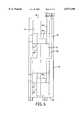
- FIG. 2is a representation of the patch panel 8 with a housing generally designated 10.
- the patch panel 8includes a front face 22 with a plurality of the first electrical connectors 12. Additionally, the patch panel 8 includes a rear face 24. The rear face 24 also has a plurality of the electrical connectors, namely second electrical connectors 14 (see FIG. 6).
- the housing 10supports cassettes or cable cartridges 40. Each cartridge 40 has two first electrical connectors 12 and two second electrical connectors 14.
- the inventionprovides a plurality of cartridges 40 which each support two spools 30.
- Each cartridge 40preferably includes a wire management element 42 on a front face 22 and a wire management element 44 on the rear face 24.
- the cartridge 40is provided to be extractable from the shell of the housing 10 as shown 2.
- a cartridge 40is removed from the shell of housing 10 allowing the spool 30 to be removed from the cartridge.
- the wire 18may be replaced on the spool 30 or a new spool 30, with wire 18 may be positioned back in the cartridge with the first contact 12 and second contact 14 disposed at the front face 22 and rear face 24 respectively. This arrangement provides a practical mechanism for replacing lines which do not function or do not perform to the proper level.
- FIG. 3shows the cartridge 40 removed from the housing 10.
- a front plate 41covers the spools 30.
- each cartridge 40includes a support structure 43 with a front spool receiving area 46 as well as a rear spool receiving area 48.
- the two first electrical connectors 12, the two second electrical connectors 14 and the associated wires 18are provided with each cartridge 40.
- This arrangementprovides for a connector density which is similar to standard patch panels, namely rows of two connectors.
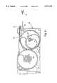
- Each spool 30is connected to the cartridge 40 with an interior surface of its core 31 supported via a bearing element 50.
- Bearing element 50is preferably merely a cylindrical element for supporting the spool 30 in rotation.
- spring means 17in the form of a spring motor 52 is provided for assisting in retracting the wire portion 18', after it has been extended.
- the spring 52provides a rotational bias whereby as the wire portion 18' is paid out, there is a force exerted on the wire for retracting the wire.
- ratchet means 53is provided associated with each of the front spool receiving region 46 and the rear spool receiving region 48.
- Each rachet meansincludes teeth 56 provided on each spool 30 and a pawl element 60 connected to a spring 61.
- the pawl element 60can be moved into engagement with the gear teeth of a transmission gear or gear teeth 56, thereby holding the spool 30 in position and also eliminating the rotational biasing force which otherwise would be applied to wire 18.
- the electrical interconnection means 16is based on a single continuous line (wire) 18 which extends from the first electrical connector 12 to the second electrical connector 14.
- This interconnection means 16is provided in the form of a wire 18 which is stored in the patch panel 8 until it is used. During use, the wire portion 18' extends out of the patch panel.
- the feeding and spools 30pay out the connection wire portion 18' and store the connection wire portion 18".
- the connection wire portion 18'may be retracted to position it for storage.
- a feeding and storage meansis formed of the spool generally designated 30, a spring means 17 and the rachet means (including pawl element 60, teeth 56 and spring 61).
- each spool 30includes a payout spool half 32 and a storage spool half 34.
- the payout spool half 32provides the space for storing the extendable wire portion 18' which is to be paid out, to the extent necessary to connect the first connection means 12.
- the other half. of the wire 18, the stored portion 18"is disposed in the storage area 34.
- This stored portion 18" in storage area 34is approximately equal to one half of the length of the extendable portion 18' (one half of the maximum amount of wire 18 which can be extended out of the patch cord 10).
- wire 18is single, continuous integral wire extending from the first connector 12 to the second connector 14, there is a transition portion 18t between wire portions 18' and 18", in the core 31 of the spool 30.
- the length of wire from connector 14 to the spool storage space 34is preferably constant (does not change). This provides a significant advantage according to the invention that a single non-interrupted electrical line is provided from the first connector 12 to the second connector 14. This materially enhances the performance of the device and removes problems with regard to transmission of an electrical signal between moving parts. However, this results in the significant requirement that the maximum payout length of extendable wire 18' is limited by the storage of the remaining portion of wire 18.
- the connector 14is directly connected to wire 18 which feeds into the storage space 34 and crosses over into the payout region 32.
- the distance between the crossover point and the point in which wire 18t exits the spool 30,substantially corresponds to the distance from the crossover point to the first connection element 12.
- the same relationshipis provided with regard to the rear spool 30 and associated front first connecting element 12, rear first connecting element 14 and interconnection wire 18.
- the inventionprovides a unitary or single wire connecting the first wire connection element and the second wire connection element.
- a single non-interrupted continuous wire 18to provide for the wire interconnection means 16
- Using an equal length for storagecould lower the performance of the patch panel. This also could be problematic with regard to the physical storage of the portion of the wire 18 which remains fully within the patch panel at all times.
- a wrapping techniqueis used for the stored portion of the wire 18". This allows only approximately half of the wire to be deployed on the storage space side 34 as compared to the payout side 32.
- the wire 18' which is paid out from the payout space 32is about twice the length of wire 18", to be deployed within the storage space 34.
- FIG. 7shows the state of the stored wire portion 18", and the spool storage space 34 when the extendable part of wire portion 18' is in a retracted position.
- the stored wire portion 18"is fully wound. Rotation in a clockwise direction, and extension of the wire portion 18' from the payout region 32, will result in the stored wire portion 18" being unwound as shown in FIG. 8.
- the distance between the second wire connection element 14 and the periphery of the spoolis fixed such that the stored wire portion 18" within the space 34 unwinds but is maintained within the space 34.
- the wire 18'is almost 50% extracted from the payout region 32.
- the wire portion 18" within the storage space 34is almost fully unwound.
- FIG. 9shows the extendable wire portion 18' fully extended from the payout space 32.
- the stored wire portion 18" in the storage space 34is fully wound about the spool core 31 (center) of the storage space 34 in a second rotational direction.
- the extendable wire portion 18'cannot be further extended from the payout space 32.
- the ratchet means 53allows the wire 18 to be extended to any distance between the maximum extension length and the minimum extension length and then held in that position. This is convenient as the spring force of spring means 17 is no longer applied to the spool when the pawl element 60 is engaged with teeth 56 and therefore the wire 18 is no longer strained by the force of the spring motor 52. This is also a practical arrangement such that the technician rewiring or wiring using the patch panel of the invention can extend the wire to the length needed without the wire snapping back into the retracted position.
Landscapes
- Engineering & Computer Science (AREA)
- Computer Networks & Wireless Communication (AREA)
- Details Of Connecting Devices For Male And Female Coupling (AREA)
- Coupling Device And Connection With Printed Circuit (AREA)
- Structure Of Telephone Exchanges (AREA)
- Connector Housings Or Holding Contact Members (AREA)
- Storing, Repeated Paying-Out, And Re-Storing Of Elongated Articles (AREA)
- Connections Arranged To Contact A Plurality Of Conductors (AREA)
Abstract
Description
Claims (20)
Priority Applications (14)
| Application Number | Priority Date | Filing Date | Title |
|---|---|---|---|
| US09/001,914US6077108A (en) | 1997-12-31 | 1997-12-31 | Patch panel with retractable patch cord |
| EP98123266AEP0928053A3 (en) | 1997-12-31 | 1998-12-07 | Patch panel |
| AU97155/98AAU742754B2 (en) | 1997-12-31 | 1998-12-17 | Patch panel |
| SG1998005875ASG73598A1 (en) | 1997-12-31 | 1998-12-21 | Patch panel |
| NO986018ANO986018L (en) | 1997-12-31 | 1998-12-21 | Wiring board |
| JP10364624AJPH11313347A (en) | 1997-12-31 | 1998-12-22 | Patch panel |
| CA002256905ACA2256905A1 (en) | 1997-12-31 | 1998-12-22 | Patch panel with retractable patch cord |
| TW087121540ATW416173B (en) | 1997-12-31 | 1998-12-23 | Patch panel |
| RU98123595/09ARU2194345C2 (en) | 1997-12-31 | 1998-12-25 | Patchboard |
| KR1019980059510AKR19990063528A (en) | 1997-12-31 | 1998-12-28 | Wiring board |
| ARP980106685AAR014186A1 (en) | 1997-12-31 | 1998-12-28 | INTERCONNECTION PANEL |
| BR9805731-6ABR9805731A (en) | 1997-12-31 | 1998-12-29 | Connection panel. |
| ZA9811936AZA9811936B (en) | 1997-12-31 | 1998-12-30 | Patch panel. |
| CN98125970ACN1109383C (en) | 1997-12-31 | 1998-12-31 | Patch panel |
Applications Claiming Priority (1)
| Application Number | Priority Date | Filing Date | Title |
|---|---|---|---|
| US09/001,914US6077108A (en) | 1997-12-31 | 1997-12-31 | Patch panel with retractable patch cord |
Publications (1)
| Publication Number | Publication Date |
|---|---|
| US6077108Atrue US6077108A (en) | 2000-06-20 |
Family
ID=21698403
Family Applications (1)
| Application Number | Title | Priority Date | Filing Date |
|---|---|---|---|
| US09/001,914Expired - Fee RelatedUS6077108A (en) | 1997-12-31 | 1997-12-31 | Patch panel with retractable patch cord |
Country Status (14)
| Country | Link |
|---|---|
| US (1) | US6077108A (en) |
| EP (1) | EP0928053A3 (en) |
| JP (1) | JPH11313347A (en) |
| KR (1) | KR19990063528A (en) |
| CN (1) | CN1109383C (en) |
| AR (1) | AR014186A1 (en) |
| AU (1) | AU742754B2 (en) |
| BR (1) | BR9805731A (en) |
| CA (1) | CA2256905A1 (en) |
| NO (1) | NO986018L (en) |
| RU (1) | RU2194345C2 (en) |
| SG (1) | SG73598A1 (en) |
| TW (1) | TW416173B (en) |
| ZA (1) | ZA9811936B (en) |
Cited By (42)
| Publication number | Priority date | Publication date | Assignee | Title |
|---|---|---|---|---|
| US6315598B1 (en)* | 2000-02-01 | 2001-11-13 | Adc Telecommunications, Inc. | Outlet box with cable management spool |
| US6325665B1 (en)* | 2000-04-25 | 2001-12-04 | Yu-Lin Chung | Power adapter with cable storage device |
| US6433274B1 (en)* | 2000-01-06 | 2002-08-13 | Mobility Electronic, Inc. | Power converter device |
| WO2002082607A1 (en)* | 2001-04-04 | 2002-10-17 | Pandacom Networking Ag | Device for the temporary wiring, especially emergency wiring, of communication networks |
| US20020187675A1 (en)* | 2001-05-09 | 2002-12-12 | Mcmullin Faris W. | Integrated cord take-up assembly |
| US20040102085A1 (en)* | 2002-11-22 | 2004-05-27 | Benq Corporation | Wire-collecting device for computer accessories |
| US6780047B1 (en) | 2000-03-24 | 2004-08-24 | Intel Corporation | Network communications system |
| US20050213313A1 (en)* | 2003-11-19 | 2005-09-29 | Israel Baumberg | Modular electroluminescent flexible light source |
| US20060027697A1 (en)* | 2004-08-05 | 2006-02-09 | Darko Gojanovic | Retractable cord device for storing a separate cord and method of storing the same |
| US20060243845A1 (en)* | 2005-02-21 | 2006-11-02 | Harald Wegner | Wire-winding device for earphones, especially hands free kits for mobile phones |
| US20060286861A1 (en)* | 2005-06-17 | 2006-12-21 | Iq Innovations Llc | Ecg cable management system |
| US7220144B1 (en) | 2000-02-01 | 2007-05-22 | Adc Telecommunications, Inc. | Multimedia outlet box |
| US20080037945A1 (en)* | 2006-08-09 | 2008-02-14 | Jeff Gniadek | Cable payout systems and methods |
| US20090247854A1 (en)* | 2008-03-27 | 2009-10-01 | Nellcor Puritan Bennett Llc | Retractable Sensor Cable For A Pulse Oximeter |
| SG158755A1 (en)* | 2008-07-10 | 2010-02-26 | Ko Oon Joo | Patch cord arrangement set |
| US20110024544A1 (en)* | 2009-07-30 | 2011-02-03 | Mark Smrha | Locking spool for telecommunications cable and method |
| US20110024543A1 (en)* | 2009-07-30 | 2011-02-03 | Mark Smrha | Spool for telecommunications cable and method |
| US7901241B1 (en)* | 2007-12-12 | 2011-03-08 | Larkin Kevin B | Dual level modular network cable hub |
| US8151820B1 (en)* | 2008-05-22 | 2012-04-10 | Larkin Kevin B | Modular multipurpose patient connect hub |
| WO2011163464A3 (en)* | 2010-06-23 | 2012-04-19 | Adc Telecommunications, Inc. | Telecommunications assembly |
| US20120123225A1 (en)* | 2009-09-09 | 2012-05-17 | Youhanna Al-Tawil | Mouth Guard for Detecting and Monitoring Bite Pressures |
| US8720810B2 (en) | 2011-02-11 | 2014-05-13 | Adc Telecommunications, Inc. | Spool for telecommunications cable and method |
| US20140224913A1 (en)* | 2013-02-14 | 2014-08-14 | Haworth, Inc. | Cable retractor |
| TWI450463B (en)* | 2012-06-07 | 2014-08-21 | Alltop Technology Co Ltd | Charger and charging assembly having the same |
| US20140377983A1 (en)* | 2013-06-20 | 2014-12-25 | Amx, Llc | Retractable cable and cable rewind spool configuration |
| US20150241473A1 (en)* | 2014-02-24 | 2015-08-27 | EADS Contrucciones Aeronauticas S.A. | System for performing electrical tests to electrical wiring harnesses |
| US9126802B2 (en) | 2012-04-30 | 2015-09-08 | Adc Telecommunications, Inc. | Payout spool with automatic cable disconnect/reconnect |
| US9166346B2 (en)* | 2014-01-13 | 2015-10-20 | International Business Machines Corporation | Retractable interconnect device configured to switch between electrical paths |
| WO2015164738A1 (en)* | 2014-04-25 | 2015-10-29 | Adc Telecommunications, Inc. | Managed connectivity in cable spool assemblies |
| US9500831B2 (en) | 2012-04-30 | 2016-11-22 | Commscope Technologies Llc | Cable payout cassette with single layer cable storage area |
| EP3089283A4 (en)* | 2013-12-23 | 2017-07-05 | Gree Electric Appliances, Inc. of Zhuhai | Coiling device and household appliance having the same |
| US9722407B2 (en) | 2012-04-30 | 2017-08-01 | Commscope Technologies Llc | Guided cable storage assembly with switchbacks |
| US9908742B2 (en) | 2012-04-30 | 2018-03-06 | Commscope Technologies Llc | Cable storage spool with center feed |
| US10130276B2 (en) | 2014-08-06 | 2018-11-20 | Emmanual, LLC | Medical apparatus |
| US10234648B2 (en) | 2007-08-06 | 2019-03-19 | Commscope Technologies Llc | Fiber optic enclosure with internal cable spool |
| US10236648B2 (en) | 2016-06-01 | 2019-03-19 | Server Technology, Inc. | Power distribution unit system incorporating smart cables and adapters |
| US10371914B2 (en) | 2011-06-24 | 2019-08-06 | Commscope Technologies Llc | Fiber termination enclosure with modular plate assemblies |
| US10517188B2 (en)* | 2016-06-01 | 2019-12-24 | Server Technology, Inc. | Power distribution unit with cord storage cartridge |
| US10545305B2 (en) | 2012-12-19 | 2020-01-28 | CommScope Connectivity Belgium BVBA | Distribution device with incrementally added splitters |
| US10627592B2 (en) | 2007-05-07 | 2020-04-21 | Commscope Technologies Llc | Fiber optic assembly with cable spool |
| US20220029367A1 (en)* | 2018-12-04 | 2022-01-27 | Samsung Electronics Co., Ltd. | Multi-adapter comprising connector connected to externally extendable cable |
| US11320403B2 (en)* | 2017-06-21 | 2022-05-03 | Vertex Components Limited | Cable management assembly |
Families Citing this family (16)
| Publication number | Priority date | Publication date | Assignee | Title |
|---|---|---|---|---|
| DE10019459C1 (en)* | 2000-04-19 | 2001-12-20 | Lothar Mueller | Cable drum with extendable cable sections |
| US8798427B2 (en) | 2007-09-05 | 2014-08-05 | Corning Cable Systems Llc | Fiber optic terminal assembly |
| CN102209921B (en) | 2008-10-09 | 2015-11-25 | 康宁光缆系统有限公司 | There is the fibre-optic terminus supported from the adapter panel of the input and output optical fiber of optical splitters |
| US8879882B2 (en) | 2008-10-27 | 2014-11-04 | Corning Cable Systems Llc | Variably configurable and modular local convergence point |
| EP2237091A1 (en) | 2009-03-31 | 2010-10-06 | Corning Cable Systems LLC | Removably mountable fiber optic terminal |
| US8467651B2 (en) | 2009-09-30 | 2013-06-18 | Ccs Technology Inc. | Fiber optic terminals configured to dispose a fiber optic connection panel(s) within an optical fiber perimeter and related methods |
| US9547144B2 (en) | 2010-03-16 | 2017-01-17 | Corning Optical Communications LLC | Fiber optic distribution network for multiple dwelling units |
| US8792767B2 (en) | 2010-04-16 | 2014-07-29 | Ccs Technology, Inc. | Distribution device |
| WO2012054454A2 (en) | 2010-10-19 | 2012-04-26 | Corning Cable Systems Llc | Transition box for multiple dwelling unit fiber optic distribution network |
| US9219546B2 (en) | 2011-12-12 | 2015-12-22 | Corning Optical Communications LLC | Extremely high frequency (EHF) distributed antenna systems, and related components and methods |
| US10110307B2 (en) | 2012-03-02 | 2018-10-23 | Corning Optical Communications LLC | Optical network units (ONUs) for high bandwidth connectivity, and related components and methods |
| US9004778B2 (en) | 2012-06-29 | 2015-04-14 | Corning Cable Systems Llc | Indexable optical fiber connectors and optical fiber connector arrays |
| US9049500B2 (en) | 2012-08-31 | 2015-06-02 | Corning Cable Systems Llc | Fiber optic terminals, systems, and methods for network service management |
| US8909019B2 (en) | 2012-10-11 | 2014-12-09 | Ccs Technology, Inc. | System comprising a plurality of distribution devices and distribution device |
| CN111290545B (en)* | 2020-02-21 | 2021-08-06 | 浙江优兰电气有限公司 | Network equipment based on robot block chain |
| CN113690741B (en)* | 2021-08-30 | 2024-07-19 | 江苏长高电气有限公司 | Side outgoing line type switch cabinet convenient to wire arrangement and maintenance |
Citations (3)
| Publication number | Priority date | Publication date | Assignee | Title |
|---|---|---|---|---|
| US4722494A (en)* | 1986-10-17 | 1988-02-02 | Odetics, Inc. | Cable retractor assembly for taking up slack of a cable |
| US5481607A (en)* | 1994-09-30 | 1996-01-02 | Hsiao; Tien J. | Automatic rewinding device for the conductor of a telephone transmitter |
| US5494446A (en)* | 1994-01-05 | 1996-02-27 | Delucia; Eugene | Receptacle mounted, retractable, extension cord |
Family Cites Families (7)
| Publication number | Priority date | Publication date | Assignee | Title |
|---|---|---|---|---|
| US3821496A (en)* | 1972-03-09 | 1974-06-28 | Troy Malone De | Electrical conductor adjusting means for medical diagnostic equipment |
| DE2804478C2 (en)* | 1978-01-31 | 1982-11-25 | Krone Gmbh, 1000 Berlin | Electrical clamp connector for the production of a contact on a fixed connection element without soldering, screwing or stripping, in particular for telecommunication line technology |
| SU1334234A1 (en)* | 1985-07-29 | 1987-08-30 | Предприятие П/Я Р-6076 | Panel for securing h.v.indicator |
| US5168969A (en)* | 1991-12-13 | 1992-12-08 | Mayhew Joseph C | Cable re-winder box for electronic game controllers |
| DE69318215T2 (en)* | 1992-06-10 | 1998-10-29 | Rit Technologies Ltd., Tel Aviv | Scanner for patch panel |
| FR2701345B1 (en)* | 1993-02-05 | 1995-03-24 | Michel Constant | Distributor system for modular structured cabling. |
| US5913487A (en)* | 1998-04-17 | 1999-06-22 | Leatherman; Michael | Retractable cable system |
- 1997
- 1997-12-31USUS09/001,914patent/US6077108A/ennot_activeExpired - Fee Related
- 1998
- 1998-12-07EPEP98123266Apatent/EP0928053A3/ennot_activeWithdrawn
- 1998-12-17AUAU97155/98Apatent/AU742754B2/ennot_activeCeased
- 1998-12-21SGSG1998005875Apatent/SG73598A1/enunknown
- 1998-12-21NONO986018Apatent/NO986018L/enunknown
- 1998-12-22CACA002256905Apatent/CA2256905A1/ennot_activeAbandoned
- 1998-12-22JPJP10364624Apatent/JPH11313347A/enactivePending
- 1998-12-23TWTW087121540Apatent/TW416173B/ennot_activeIP Right Cessation
- 1998-12-25RURU98123595/09Apatent/RU2194345C2/ennot_activeIP Right Cessation
- 1998-12-28KRKR1019980059510Apatent/KR19990063528A/ennot_activeWithdrawn
- 1998-12-28ARARP980106685Apatent/AR014186A1/enunknown
- 1998-12-29BRBR9805731-6Apatent/BR9805731A/ennot_activeIP Right Cessation
- 1998-12-30ZAZA9811936Apatent/ZA9811936B/enunknown
- 1998-12-31CNCN98125970Apatent/CN1109383C/ennot_activeExpired - Fee Related
Patent Citations (3)
| Publication number | Priority date | Publication date | Assignee | Title |
|---|---|---|---|---|
| US4722494A (en)* | 1986-10-17 | 1988-02-02 | Odetics, Inc. | Cable retractor assembly for taking up slack of a cable |
| US5494446A (en)* | 1994-01-05 | 1996-02-27 | Delucia; Eugene | Receptacle mounted, retractable, extension cord |
| US5481607A (en)* | 1994-09-30 | 1996-01-02 | Hsiao; Tien J. | Automatic rewinding device for the conductor of a telephone transmitter |
Cited By (107)
| Publication number | Priority date | Publication date | Assignee | Title |
|---|---|---|---|---|
| US6433274B1 (en)* | 2000-01-06 | 2002-08-13 | Mobility Electronic, Inc. | Power converter device |
| US7361052B2 (en) | 2000-02-01 | 2008-04-22 | Adc Telecommunications, Inc. | Multimedia outlet box |
| US6315598B1 (en)* | 2000-02-01 | 2001-11-13 | Adc Telecommunications, Inc. | Outlet box with cable management spool |
| US20070173111A1 (en)* | 2000-02-01 | 2007-07-26 | Adc Telecommunications, Inc. | Multimedia outlet box |
| US7220144B1 (en) | 2000-02-01 | 2007-05-22 | Adc Telecommunications, Inc. | Multimedia outlet box |
| US7038138B2 (en) | 2000-03-24 | 2006-05-02 | Intel Corporation | Network communications system |
| US6780047B1 (en) | 2000-03-24 | 2004-08-24 | Intel Corporation | Network communications system |
| US20050090151A1 (en)* | 2000-03-24 | 2005-04-28 | Ian Laity | Network communications system |
| US6325665B1 (en)* | 2000-04-25 | 2001-12-04 | Yu-Lin Chung | Power adapter with cable storage device |
| WO2002082607A1 (en)* | 2001-04-04 | 2002-10-17 | Pandacom Networking Ag | Device for the temporary wiring, especially emergency wiring, of communication networks |
| DE10116649C2 (en)* | 2001-04-04 | 2003-10-23 | Pandacom Networking Ag | Device for temporary wiring, in particular emergency wiring, of communication networks |
| US20020187675A1 (en)* | 2001-05-09 | 2002-12-12 | Mcmullin Faris W. | Integrated cord take-up assembly |
| US20040102085A1 (en)* | 2002-11-22 | 2004-05-27 | Benq Corporation | Wire-collecting device for computer accessories |
| US20050213313A1 (en)* | 2003-11-19 | 2005-09-29 | Israel Baumberg | Modular electroluminescent flexible light source |
| US20060027697A1 (en)* | 2004-08-05 | 2006-02-09 | Darko Gojanovic | Retractable cord device for storing a separate cord and method of storing the same |
| US20060243845A1 (en)* | 2005-02-21 | 2006-11-02 | Harald Wegner | Wire-winding device for earphones, especially hands free kits for mobile phones |
| US20060286861A1 (en)* | 2005-06-17 | 2006-12-21 | Iq Innovations Llc | Ecg cable management system |
| US7335053B2 (en)* | 2005-06-17 | 2008-02-26 | I.Q. Innovations, Llc | ECG cable management system |
| WO2008020997A3 (en)* | 2006-08-09 | 2008-04-03 | Adc Telecommunications Inc | Cable payout systems and methods |
| US20080037945A1 (en)* | 2006-08-09 | 2008-02-14 | Jeff Gniadek | Cable payout systems and methods |
| US8121456B2 (en) | 2006-08-09 | 2012-02-21 | Adc Telecommunications, Inc. | Cable payout systems and methods |
| US7599598B2 (en) | 2006-08-09 | 2009-10-06 | Adc Telecommunications, Inc. | Cable payout systems and methods |
| US10788642B2 (en) | 2007-05-07 | 2020-09-29 | Commscope Technologies Llc | Fiber optic assembly with cable storage arrangement |
| US11009671B2 (en) | 2007-05-07 | 2021-05-18 | Commscope Technologies Llc | Fiber optic assembly with cable storage arrangement |
| US10627592B2 (en) | 2007-05-07 | 2020-04-21 | Commscope Technologies Llc | Fiber optic assembly with cable spool |
| US12235506B2 (en) | 2007-05-07 | 2025-02-25 | Commscope Technologies Llc | Fiber optic enclosure with external cable spool |
| US10996417B2 (en) | 2007-08-06 | 2021-05-04 | Commscope Technologies Llc | Fiber optic enclosure with internal cable spool and movable cover |
| US12253734B2 (en) | 2007-08-06 | 2025-03-18 | Commscope Technologies Llc | Fiber optic enclosure with internal cable spool |
| US10996418B2 (en) | 2007-08-06 | 2021-05-04 | Commscope Technologies Llc | Connecting subscribers to a fiber optic network using a cable spool |
| US12019301B2 (en) | 2007-08-06 | 2024-06-25 | Commscope Technologies Llc | Fiber optic enclosure with internal cable spool |
| US10895705B2 (en) | 2007-08-06 | 2021-01-19 | Commscope Technologies Llc | Fiber optic enclosure with internal cable spool |
| US10234648B2 (en) | 2007-08-06 | 2019-03-19 | Commscope Technologies Llc | Fiber optic enclosure with internal cable spool |
| US10712518B2 (en) | 2007-08-06 | 2020-07-14 | Commscope Technologies Llc | Fiber optic enclosure with lockable internal cable spool |
| US11573390B2 (en) | 2007-08-06 | 2023-02-07 | Commscope Technologies Llc | Fiber optic enclosure with internal cable spool |
| US10606017B2 (en) | 2007-08-06 | 2020-03-31 | Commscope Technologies Llc | Fiber optic payout assembly including cable spool |
| US10606015B2 (en) | 2007-08-06 | 2020-03-31 | Commscope Technologies Llc | Fiber optic payout assembly including cable spool |
| US10495836B2 (en) | 2007-08-06 | 2019-12-03 | Commscope Technologies Llc | Fiber optic payout assembly including cable spool |
| US10247897B2 (en) | 2007-08-06 | 2019-04-02 | Commscope Technologies Llc | Fiber optic enclosure with internal cable spool |
| US7901241B1 (en)* | 2007-12-12 | 2011-03-08 | Larkin Kevin B | Dual level modular network cable hub |
| US20090247854A1 (en)* | 2008-03-27 | 2009-10-01 | Nellcor Puritan Bennett Llc | Retractable Sensor Cable For A Pulse Oximeter |
| US8151820B1 (en)* | 2008-05-22 | 2012-04-10 | Larkin Kevin B | Modular multipurpose patient connect hub |
| SG158755A1 (en)* | 2008-07-10 | 2010-02-26 | Ko Oon Joo | Patch cord arrangement set |
| US8238707B2 (en) | 2009-07-30 | 2012-08-07 | Adc Telecommunications, Inc. | Locking spool for telecommunications cable and method |
| US20110024543A1 (en)* | 2009-07-30 | 2011-02-03 | Mark Smrha | Spool for telecommunications cable and method |
| US20110024544A1 (en)* | 2009-07-30 | 2011-02-03 | Mark Smrha | Locking spool for telecommunications cable and method |
| US8474742B2 (en) | 2009-07-30 | 2013-07-02 | Adc Telecommunications, Inc. | Spool for telecommunications cable and method |
| US20120123225A1 (en)* | 2009-09-09 | 2012-05-17 | Youhanna Al-Tawil | Mouth Guard for Detecting and Monitoring Bite Pressures |
| US8961437B2 (en)* | 2009-09-09 | 2015-02-24 | Youhanna Al-Tawil | Mouth guard for detecting and monitoring bite pressures |
| US11789226B2 (en) | 2010-06-23 | 2023-10-17 | Commscope Technologies Llc | Telecommunications assembly |
| US10884211B2 (en) | 2010-06-23 | 2021-01-05 | Commscope Technologies Llc | Telecommunications assembly |
| US20140178025A1 (en)* | 2010-06-23 | 2014-06-26 | Adc Telecommunications, Inc. | Telecommunications Assembly |
| US9341802B2 (en) | 2010-06-23 | 2016-05-17 | Commscope Technologies Llc | Telecommunications assembly |
| WO2011163464A3 (en)* | 2010-06-23 | 2012-04-19 | Adc Telecommunications, Inc. | Telecommunications assembly |
| US12235504B2 (en) | 2010-06-23 | 2025-02-25 | Commscope Technologies Llc | Telecommunications assembly |
| US9678296B2 (en) | 2010-06-23 | 2017-06-13 | Commscope Technologies Llc | Telecommunications assembly |
| AU2011270834B2 (en)* | 2010-06-23 | 2015-02-19 | Commscope Technologies Llc | Telecommunications assembly |
| US11402595B2 (en) | 2010-06-23 | 2022-08-02 | Commscope Technologies Llc | Telecommunications assembly |
| US8565572B2 (en) | 2010-06-23 | 2013-10-22 | Adc Telecommunications, Inc. | Telecommunications assembly |
| US10268014B2 (en) | 2010-06-23 | 2019-04-23 | Commscope Technologies Llc | Telecommunications assembly |
| US9170392B2 (en) | 2010-06-23 | 2015-10-27 | Tyco Electronics Services Gmbh | Telecommunications assembly |
| US8938147B2 (en)* | 2010-06-23 | 2015-01-20 | Adc Telecommunications, Inc. | Telecommunications assembly |
| US10627593B2 (en) | 2010-06-23 | 2020-04-21 | Commscope Technologies Llc | Telecommunications assembly |
| US9995898B2 (en) | 2010-06-23 | 2018-06-12 | Commscope Technologies Llc | Telecommunications assembly |
| US10126516B1 (en) | 2010-06-23 | 2018-11-13 | Commscope Technologies Llc | Telecommunications assembly |
| US8720810B2 (en) | 2011-02-11 | 2014-05-13 | Adc Telecommunications, Inc. | Spool for telecommunications cable and method |
| US11988883B2 (en) | 2011-06-24 | 2024-05-21 | Commscope Technologies Llc | Fiber termination enclosure with modular plate assemblies |
| US10935744B2 (en) | 2011-06-24 | 2021-03-02 | Commscope Technologies Llc | Fiber termination enclosure with modular plate assemblies |
| US11327262B2 (en) | 2011-06-24 | 2022-05-10 | Commscope Technologies Llc | Fiber termination enclosure with modular plate assemblies |
| US10371914B2 (en) | 2011-06-24 | 2019-08-06 | Commscope Technologies Llc | Fiber termination enclosure with modular plate assemblies |
| US10502916B2 (en) | 2011-06-24 | 2019-12-10 | Commscope Technologies Llc | Fiber termination enclosure with modular plate assemblies |
| US11624884B2 (en) | 2011-06-24 | 2023-04-11 | Commscope Technologies Llc | Fiber termination enclosure with modular plate assemblies |
| US9500831B2 (en) | 2012-04-30 | 2016-11-22 | Commscope Technologies Llc | Cable payout cassette with single layer cable storage area |
| US9908742B2 (en) | 2012-04-30 | 2018-03-06 | Commscope Technologies Llc | Cable storage spool with center feed |
| US9722407B2 (en) | 2012-04-30 | 2017-08-01 | Commscope Technologies Llc | Guided cable storage assembly with switchbacks |
| US9939600B2 (en) | 2012-04-30 | 2018-04-10 | Commscope Technologies Llc | Optical fiber disconnect/reconnect apparatus |
| US9126802B2 (en) | 2012-04-30 | 2015-09-08 | Adc Telecommunications, Inc. | Payout spool with automatic cable disconnect/reconnect |
| US10625978B2 (en) | 2012-04-30 | 2020-04-21 | Commscope Technologies Llc | Cable storage spool with center feed |
| TWI450463B (en)* | 2012-06-07 | 2014-08-21 | Alltop Technology Co Ltd | Charger and charging assembly having the same |
| US10545305B2 (en) | 2012-12-19 | 2020-01-28 | CommScope Connectivity Belgium BVBA | Distribution device with incrementally added splitters |
| US9327938B2 (en)* | 2013-02-14 | 2016-05-03 | Haworth, Inc. | Cable retractor |
| US20140224913A1 (en)* | 2013-02-14 | 2014-08-14 | Haworth, Inc. | Cable retractor |
| US9680262B2 (en)* | 2013-06-20 | 2017-06-13 | Amx Llc | Retractable cable and cable rewind spool configuration |
| US9309087B2 (en)* | 2013-06-20 | 2016-04-12 | Amx Llc | Retractable cable and cable rewind spool configuration |
| US20170093097A1 (en)* | 2013-06-20 | 2017-03-30 | Amx Llc | Retractable cable and cable rewind spool configuration |
| US10483699B2 (en)* | 2013-06-20 | 2019-11-19 | Harman Professional, Inc | Retractable cable and cable rewind spool configuration |
| US20140377983A1 (en)* | 2013-06-20 | 2014-12-25 | Amx, Llc | Retractable cable and cable rewind spool configuration |
| US9553413B2 (en)* | 2013-06-20 | 2017-01-24 | Amx Llc | Retractable cable and cable rewind spool configuration |
| US20170279229A1 (en)* | 2013-06-20 | 2017-09-28 | Amx, Llc | Retractable cable and cable rewind spool configuration |
| US9425563B2 (en)* | 2013-06-20 | 2016-08-23 | Amx Llc | Retractable cable and cable rewind spool configuration |
| US9960546B2 (en) | 2013-12-23 | 2018-05-01 | Gree Electric Appliances, Inc. Of Zhuhai | Coiling device and household appliance having the same |
| EP3089283A4 (en)* | 2013-12-23 | 2017-07-05 | Gree Electric Appliances, Inc. of Zhuhai | Coiling device and household appliance having the same |
| US9166346B2 (en)* | 2014-01-13 | 2015-10-20 | International Business Machines Corporation | Retractable interconnect device configured to switch between electrical paths |
| US9664722B2 (en)* | 2014-02-24 | 2017-05-30 | Eads Construcciones Aeronauticas, S.A. | System for performing electrical tests to electrical wiring harnesses |
| US20150241473A1 (en)* | 2014-02-24 | 2015-08-27 | EADS Contrucciones Aeronauticas S.A. | System for performing electrical tests to electrical wiring harnesses |
| WO2015164738A1 (en)* | 2014-04-25 | 2015-10-29 | Adc Telecommunications, Inc. | Managed connectivity in cable spool assemblies |
| US10649166B2 (en) | 2014-04-25 | 2020-05-12 | Commscope Technologies Llc | Selectively lockable cable spool assemblies for communications panels |
| US10203465B2 (en) | 2014-04-25 | 2019-02-12 | Commscope Technologies Llc | Managed connectivity in cable spool assemblies |
| US10130276B2 (en) | 2014-08-06 | 2018-11-20 | Emmanual, LLC | Medical apparatus |
| US11557868B2 (en) | 2016-06-01 | 2023-01-17 | Server Technology, Inc. | Power distribution unit system incorporating smart cables and adapters |
| US11375636B2 (en) | 2016-06-01 | 2022-06-28 | Server Technology, Inc. | Power distribution unit with cord storage cartridge |
| US11901681B2 (en) | 2016-06-01 | 2024-02-13 | Server Technology, Inc. | Power distribution unit system incorporating smart cables and adapters |
| US11095081B2 (en) | 2016-06-01 | 2021-08-17 | Server Technology, Inc. | Power distribution unit system incorporating smart cables and adapters |
| US10236648B2 (en) | 2016-06-01 | 2019-03-19 | Server Technology, Inc. | Power distribution unit system incorporating smart cables and adapters |
| US10517188B2 (en)* | 2016-06-01 | 2019-12-24 | Server Technology, Inc. | Power distribution unit with cord storage cartridge |
| US11320403B2 (en)* | 2017-06-21 | 2022-05-03 | Vertex Components Limited | Cable management assembly |
| US11742627B2 (en)* | 2018-12-04 | 2023-08-29 | Samsung Electronics Co., Ltd. | Multi-adapter comprising connector connected to externally extendable cable |
| US20220029367A1 (en)* | 2018-12-04 | 2022-01-27 | Samsung Electronics Co., Ltd. | Multi-adapter comprising connector connected to externally extendable cable |
Also Published As
| Publication number | Publication date |
|---|---|
| NO986018D0 (en) | 1998-12-21 |
| EP0928053A2 (en) | 1999-07-07 |
| SG73598A1 (en) | 2000-06-20 |
| AU9715598A (en) | 1999-07-22 |
| CA2256905A1 (en) | 1999-06-30 |
| CN1224257A (en) | 1999-07-28 |
| RU2194345C2 (en) | 2002-12-10 |
| NO986018L (en) | 2000-07-03 |
| AR014186A1 (en) | 2001-02-07 |
| CN1109383C (en) | 2003-05-21 |
| AU742754B2 (en) | 2002-01-10 |
| BR9805731A (en) | 2000-01-18 |
| KR19990063528A (en) | 1999-07-26 |
| JPH11313347A (en) | 1999-11-09 |
| TW416173B (en) | 2000-12-21 |
| ZA9811936B (en) | 2000-06-30 |
| EP0928053A3 (en) | 2001-01-24 |
Similar Documents
| Publication | Publication Date | Title |
|---|---|---|
| US6077108A (en) | Patch panel with retractable patch cord | |
| US11398865B2 (en) | Rapid deployment indexing terminal arrangement | |
| EP2312716B1 (en) | Retractable cord reel | |
| US8474742B2 (en) | Spool for telecommunications cable and method | |
| US8121456B2 (en) | Cable payout systems and methods | |
| US6019304A (en) | Retractable reel with channeled ratchet mechanism | |
| US7680386B2 (en) | Retractable module for patch cords | |
| US6059213A (en) | Reel device | |
| US10566747B2 (en) | Telecommunications assembly with patch cord storage | |
| US20060006038A1 (en) | Extendible musical instrument cable | |
| WO2014190281A1 (en) | Passive distribution system using fiber indexing | |
| US5923807A (en) | Storage apparatus for optical fiber | |
| CN210326290U (en) | Cable test adapter | |
| HK1021593A (en) | One-piece dispensing system and method for making same |
Legal Events
| Date | Code | Title | Description |
|---|---|---|---|
| AS | Assignment | Owner name:KRONE AKTIENGESELLSCHAFT, GERMANY Free format text:ASSIGNMENT OF ASSIGNORS INTEREST;ASSIGNORS:LORSCHEIDER, JORG;ZALESKY, DEAN R.;LOTINSKY, PETER J.;REEL/FRAME:008952/0678 Effective date:19971218 | |
| FEPP | Fee payment procedure | Free format text:PAYOR NUMBER ASSIGNED (ORIGINAL EVENT CODE: ASPN); ENTITY STATUS OF PATENT OWNER: LARGE ENTITY | |
| AS | Assignment | Owner name:KRONE GMBH, GERMANY Free format text:ASSIGNMENT OF ASSIGNORS INTEREST;ASSIGNOR:KRONE AKTIENGESELLSCHAFT;REEL/FRAME:010804/0358 Effective date:19991223 | |
| FPAY | Fee payment | Year of fee payment:4 | |
| SULP | Surcharge for late payment | ||
| AS | Assignment | Owner name:APTUS 50. GMBH, GERMANY Free format text:DIVESTMENT AGREEMENT;ASSIGNOR:KRONE GMBH;REEL/FRAME:019009/0704 Effective date:20040830 Owner name:KRONE GMBH, GERMANY Free format text:CHANGE OF NAME;ASSIGNOR:APTUS 50. GMBH;REEL/FRAME:019009/0682 Effective date:20040830 Owner name:ADC GMBH, GERMANY Free format text:CHANGE OF NAME;ASSIGNOR:KRONE GMBH;REEL/FRAME:019015/0074 Effective date:20050406 | |
| FPAY | Fee payment | Year of fee payment:8 | |
| REMI | Maintenance fee reminder mailed | ||
| LAPS | Lapse for failure to pay maintenance fees | ||
| STCH | Information on status: patent discontinuation | Free format text:PATENT EXPIRED DUE TO NONPAYMENT OF MAINTENANCE FEES UNDER 37 CFR 1.362 | |
| FP | Lapsed due to failure to pay maintenance fee | Effective date:20120620 | |
| AS | Assignment | Owner name:COMMSCOPE TECHNOLOGIES LLC, NORTH CAROLINA Free format text:ASSIGNMENT OF ASSIGNORS INTEREST;ASSIGNOR:COMMSCOPE EMEA LIMITED;REEL/FRAME:037012/0001 Effective date:20150828 |