US6077026A - Programmable substrate support for a substrate positioning system - Google Patents
Programmable substrate support for a substrate positioning systemDownload PDFInfo
- Publication number
- US6077026A US6077026AUS09/050,321US5032198AUS6077026AUS 6077026 AUS6077026 AUS 6077026AUS 5032198 AUS5032198 AUS 5032198AUS 6077026 AUS6077026 AUS 6077026A
- Authority
- US
- United States
- Prior art keywords
- substrate
- substrate support
- end effector
- support
- supports
- Prior art date
- Legal status (The legal status is an assumption and is not a legal conclusion. Google has not performed a legal analysis and makes no representation as to the accuracy of the status listed.)
- Expired - Fee Related
Links
Images


Classifications
- H—ELECTRICITY
- H01—ELECTRIC ELEMENTS
- H01L—SEMICONDUCTOR DEVICES NOT COVERED BY CLASS H10
- H01L21/00—Processes or apparatus adapted for the manufacture or treatment of semiconductor or solid state devices or of parts thereof
- H01L21/67—Apparatus specially adapted for handling semiconductor or electric solid state devices during manufacture or treatment thereof; Apparatus specially adapted for handling wafers during manufacture or treatment of semiconductor or electric solid state devices or components ; Apparatus not specifically provided for elsewhere
- H01L21/683—Apparatus specially adapted for handling semiconductor or electric solid state devices during manufacture or treatment thereof; Apparatus specially adapted for handling wafers during manufacture or treatment of semiconductor or electric solid state devices or components ; Apparatus not specifically provided for elsewhere for supporting or gripping
- H01L21/687—Apparatus specially adapted for handling semiconductor or electric solid state devices during manufacture or treatment thereof; Apparatus specially adapted for handling wafers during manufacture or treatment of semiconductor or electric solid state devices or components ; Apparatus not specifically provided for elsewhere for supporting or gripping using mechanical means, e.g. chucks, clamps or pinches
- H01L21/68707—Apparatus specially adapted for handling semiconductor or electric solid state devices during manufacture or treatment thereof; Apparatus specially adapted for handling wafers during manufacture or treatment of semiconductor or electric solid state devices or components ; Apparatus not specifically provided for elsewhere for supporting or gripping using mechanical means, e.g. chucks, clamps or pinches the wafers being placed on a robot blade, or gripped by a gripper for conveyance
- H—ELECTRICITY
- H01—ELECTRIC ELEMENTS
- H01L—SEMICONDUCTOR DEVICES NOT COVERED BY CLASS H10
- H01L21/00—Processes or apparatus adapted for the manufacture or treatment of semiconductor or solid state devices or of parts thereof
- H01L21/67—Apparatus specially adapted for handling semiconductor or electric solid state devices during manufacture or treatment thereof; Apparatus specially adapted for handling wafers during manufacture or treatment of semiconductor or electric solid state devices or components ; Apparatus not specifically provided for elsewhere
- H01L21/677—Apparatus specially adapted for handling semiconductor or electric solid state devices during manufacture or treatment thereof; Apparatus specially adapted for handling wafers during manufacture or treatment of semiconductor or electric solid state devices or components ; Apparatus not specifically provided for elsewhere for conveying, e.g. between different workstations
- H01L21/67763—Apparatus specially adapted for handling semiconductor or electric solid state devices during manufacture or treatment thereof; Apparatus specially adapted for handling wafers during manufacture or treatment of semiconductor or electric solid state devices or components ; Apparatus not specifically provided for elsewhere for conveying, e.g. between different workstations the wafers being stored in a carrier, involving loading and unloading
- H01L21/67778—Apparatus specially adapted for handling semiconductor or electric solid state devices during manufacture or treatment thereof; Apparatus specially adapted for handling wafers during manufacture or treatment of semiconductor or electric solid state devices or components ; Apparatus not specifically provided for elsewhere for conveying, e.g. between different workstations the wafers being stored in a carrier, involving loading and unloading involving loading and unloading of wafers
- H—ELECTRICITY
- H01—ELECTRIC ELEMENTS
- H01L—SEMICONDUCTOR DEVICES NOT COVERED BY CLASS H10
- H01L21/00—Processes or apparatus adapted for the manufacture or treatment of semiconductor or solid state devices or of parts thereof
- H01L21/67—Apparatus specially adapted for handling semiconductor or electric solid state devices during manufacture or treatment thereof; Apparatus specially adapted for handling wafers during manufacture or treatment of semiconductor or electric solid state devices or components ; Apparatus not specifically provided for elsewhere
- H01L21/683—Apparatus specially adapted for handling semiconductor or electric solid state devices during manufacture or treatment thereof; Apparatus specially adapted for handling wafers during manufacture or treatment of semiconductor or electric solid state devices or components ; Apparatus not specifically provided for elsewhere for supporting or gripping
- H01L21/6838—Apparatus specially adapted for handling semiconductor or electric solid state devices during manufacture or treatment thereof; Apparatus specially adapted for handling wafers during manufacture or treatment of semiconductor or electric solid state devices or components ; Apparatus not specifically provided for elsewhere for supporting or gripping with gripping and holding devices using a vacuum; Bernoulli devices
- Y—GENERAL TAGGING OF NEW TECHNOLOGICAL DEVELOPMENTS; GENERAL TAGGING OF CROSS-SECTIONAL TECHNOLOGIES SPANNING OVER SEVERAL SECTIONS OF THE IPC; TECHNICAL SUBJECTS COVERED BY FORMER USPC CROSS-REFERENCE ART COLLECTIONS [XRACs] AND DIGESTS
- Y10—TECHNICAL SUBJECTS COVERED BY FORMER USPC
- Y10S—TECHNICAL SUBJECTS COVERED BY FORMER USPC CROSS-REFERENCE ART COLLECTIONS [XRACs] AND DIGESTS
- Y10S414/00—Material or article handling
- Y10S414/135—Associated with semiconductor wafer handling
- Y10S414/137—Associated with semiconductor wafer handling including means for charging or discharging wafer cassette
Definitions
- the current inventionrelates generally to the field of handling equipment for substrates, and more particularly to programmable substrate supports for a substrate positioning system that enable automated material handling apparatus to handle different types of substrates without human intervention.
- Substratessuch as semiconductor wafers or the like, are typically transported between, and processed by, one or more automatic processing stations.
- Semiconductor wafersfor example, are typically processed in a substantially clean environment.
- Semiconductor wafersare generally flat, circular plates made of semiconducting material.
- the semiconductor chip industryis currently transitioning to a new size semiconductor wafer.
- the previous standard wafer size of 200 mm diameteris being gradually replaced with a new standard wafer size of 300 mm.
- substrate manufacturersmust be capable of handling both 200 mm and 300 mm wafers. Under the previous standard of 200 mm, chip manufacturers generally allowed the wafer handling equipment to touch the underside of 200 mm wafers.
- Substrate handling devicesare generally equipped with an end effector for holding and transporting substrates among the various processing stations.
- An end effectoris a generally flat implement for securely holding a substrate.
- An end effectoris typically configured to hold a particular size of substrate. Therefore, different sizes of substrates generally require different sizes of end effectors. Manual replacement of a first end effector with a second end effector, and vice versa, requires skilled labor and can be time consuming, resulting in higher costs and production delays.
- a programmable substrate support for a substrate positioning systemfor automatically changing substrate handling equipment according to substrate type.
- a programmable substrate supportincludes a first substrate support that mates with a second substrate support to enable a substrate positioning system to automatically switch between handling different types of substrates.
- the first substrate supportis configured to support a first type of substrate and to mount to a substrate positioning system to enable the substrate positioning system to handle substrates of the first type.
- the second substrate supportis configured to support a second type of substrate and to mate with the first substrate support to form a mated configuration to enable the substrate positioning system to handle substrates of the second type. In this manner, the first substrate support is used to process substrates of the first type and the second substrate support is mated with the first substrate support in the mated configuration to process substrates of the second type.
- the first and second substrate supportsmay include complementary couplers that engage each other when the second substrate support is joined with the first substrate support.
- the complementary couplersmay further include locating features that align the first and second substrate supports with each other when joined. The locating features may be configured to enable repeatable alignment when the first and second substrate supports are joined.
- the complementary couplersmate with zero insertion force.
- the complementary couplersinclude a positioning pin provided on the first substrate support and a corresponding slot provided on the second substrate support. The slot includes sides slanted towards a center to guide the positioning pin to the center when the first and second substrate supports are joined.
- a retention mechanismmay be used to secure the second substrate support to the first substrate support in the mated configuration. In this manner, the first and second substrate supports are securely fastened to each other to enable faster processing.
- the retention mechanismmay include vacuum apparatus to apply a vacuum to secure the second substrate support to the first substrate support.
- Other retention mechanismsare contemplated, such as electromagnetic couplers, air cylinder couplers, etc.
- the first substrate supportmay further include a first vacuum pad area that engages and grips a substrate of the first type when a vacuum is applied.
- the second substrate supportmay include a vacuum port that communicatively engages the first vacuum pad area in the mated configuration so that the second vacuum port engages and grips a substrate of the second type when a vacuum is applied.
- the vacuum portsmay be used to grip substrates to enable faster processing.
- vacuum gripis not used if it generates more particulate. Instead, each substrate is gripped only at the edges. Gripping each substrate only at the edges ensures less particulate generation, although processing occurs at a slower rate.
- the first substrate supportis an end effector that supports a semiconductor wafer having a diameter of approximately 200 millimeters.
- the second substrate supportis an end effector that supports a semiconductor wafer having a diameter of approximately 300 millimeters. In this manner, the first end effector is used to process 200 mm wafers and the second end effector is used in the mated configuration to process 300 mm wafers.
- a substrate positioning systemincludes a robot with a moveable arm, where the first substrate support is mounted to the moveable arm to enable the robot to handle substrates of the first type.
- the second substrate supportis configured to mate with the first substrate support to enable the robot to handle substrates of the second type.
- the robotpositions the first substrate support below the second substrate support and then raises the first substrate support to join the first and second substrate supports together to form the mated configuration.
- a nestis included to support the second substrate support when not being used, where the robot retrieves the second substrate support from the nest to process substrates of the second type.
- FIG. 1is a perspective view of a substrate handling device.
- FIG. 2is another perspective view of the substrate handling device showing more detail of a nest for storing an end effector.
- FIG. 3shows a first end effector that is used with the substrate handling device of FIG. 1.
- FIG. 4shows the first end effector holding a 200 mm semiconductor wafer.
- FIG. 5shows the top side of a second end effector configured to engage the first end effector for handling larger substrates.
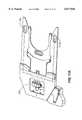
- FIG. 6shows the underside of the second end effector.
- FIG. 7shows an enlarged view of the underside of the second end effector, illustrating locating and holding features of the second end effector.
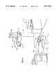
- FIG. 8depicts the second end effector which has been engaged with the top side of a first end effector.
- FIG. 9shows the underside of the coupled configuration of the second end effector and the first end effector.
- FIG. 10depicts the second end effector holding a 300 mm semiconductor wafer.
- FIG. 11ashows the second end effector adapted to grip a substrate using a vacuum pads.
- FIG. 11bshows the second end effector adapted to grip a substrate using vacuum pads which are communicatively connected to the vacuum pad area of the first end effector.
- the substrate positioning system 102includes a robot 104 having an end effector 106 configured to hold a substrate 108 and to transport the substrate 108 between at least one pod 110 having multiple slots for supporting substrates and at least one substrate processing device 112.
- the substrate processing device 112is illustrated as a prealigner, but other devices may be included in addition to the prealigner 112 substituted therefor, which perform any of a number of processing operations on the substrate, including, by way of example, inspection, sorting, and stepper functions.
- a nest 114for storing the end effector 106 when the end effector 106 is not in use.
- the robot 104includes an elongated base 116 out of which projects an extendable and rotatable shaft 117 (FIG. 2). Attached to a rotatable shoulder 119 on top of the shaft 117 is a lower link 118 connected to an upper link 120 by a pivotable elbow 122.
- the end effector 106is mounted to a wrist (not shown) on top of the upper link 120 such that the end effector 106 grips or supports a substrate 108, allowing the robot 104 to transport the substrate 108 from a pod 110 to a substrate processing device 112 via extension or retraction and rotation of the shaft 117 and/or rotation of the upper link 120 with respect to the lower link 118.
- the upper link 120pivots on the elbow 122 such that the end effector may orthogonally approach any of the pod 110, the substrate processing device 112, and the nest 114.
- substratesinclude semiconductor wafers, flat panel displays, masks, microchip modules, etc.
- the present inventionis illustrated with semiconductor wafer handling equipment. It is noted, however, that the present invention is not limited to semiconductor wafers, but is applicable to any type of substrate, such as substrates formed of glass, aluminum, Mylar®, etc. Furthermore, the present invention may be applied to printed wiring boards such as sheets of FR-4 or 1060 material or other fiberglass material, etc.
- the substratesare circular semiconductor wafers, having a diameter of 200 mm or 300 mm and a thickness of 0.031 inches. However, the substrates may have any shape, such as square or rectangular and may have any desired thickness. The present invention is not limited to any particular type, shape, size or thickness of the substrates.
- FIG. 2is a more detailed perspective view of the substrate handling device 102 which more particularly shows the nest 114.
- the nest 114consists of an open bracket 202 held by a coupling 204.
- the coupling 204is clamped to a vertical shaft 206.
- the open bracket 202is preferably rectangular in shape, with a back portion 208 for connection to the coupling 204 and first and second parallel arms 210a and 210b, positioned on either end, respectively, of the back portion 208.
- Attached to the bottom edge of either end of the first arm 210aare locator pins 212a and 212b.
- Attached to the bottom edge of the end of the first arm 210b opposite the back portion 208is a locator pin 212c.
- the locator pins 212a, 212b, and 212cserve to locate and support the end effector 106 when it is not in use.
- the robot shaft 117extends upward until the end effector 106 is positioned parallel to and slightly above the locator pins 212a, 212b, and 212c of the nest 114.
- the shaft 117pivots to align the end effector 106 with the nest 114.
- the locator pins 212a, 212b, and 212calign to corresponding locator pin mates not shown on the end effector 106 and the robot shaft 117 retracts to lower the end effector 106 such that the locator pins 212a, 212b, and 212c engage the locator pin mates of the end effector 106.
- locator pin mates 606a and 606care located on an end effector 502.
- the robot 104Through similar motions of extension or retraction and rotation of the shaft 117 and pivoting of the elbow 122, the robot 104, with an end effector 106 attached to the upper link 120, retrieves a substrate 108 from a pod 110 and moves the substrate 108 to or from a substrate processing device 112, in which certain operations are performed on the substrate 108.
- the end effector 106acts as a support device for holding the substrate 108 during precise positioning operations.
- the first end effector 302is a substantially flat broad-bladed implement that is specialized for supporting substrate of a first type.
- the first end effector 302is configured to support a 200 mm semiconductor wafer from the bottom side of the wafer during wafer processing.
- the first end effector 302is not limited to use with 200 mm semiconductor wafers, and may be proportioned to hold and/or transport other substrates and other substrate sizes.
- the first end effector 302comprises an L-shaped handle portion 301, one end of which terminates in a paddle-shaped substrate-holding portion 303 characterized by a U-shaped cutout.
- the U-shaped cutout 308is proportioned such that the first end effector 302 is able to place a substrate on a chuck (not shown) that may be located on process and/or aligning equipment (not shown).
- Each of the resulting arms 305a and 305b forming the outer boundary of the U-shaped cutout 308 of the substrate-holding area 303have at their ends buttons 306a and 306b, respectively, for contacting the substrate surface.
- the plastic buttons 306a and 306bare raised slightly from the surface of the holding area 303 of the first end effector 302 such that the area of contact between the substrate-holding area 303 of the first end effector 302 and the substrate is minimized.
- a vacuum pad area 304which creates suction for gripping a substrate (not shown) to the substrate-holding area 303 of the first end effector 302.
- the vacuum pad area 304is coupled to a vacuum line 320a to create the vacuum.
- Contact between the substrate and the first end effector 302is limited to the vacuum pad area 304 and the plastic buttons 306a and 306b.
- a vacuum port 318Located on the top surface of the handle portion 301 of the first end effector 302 is a vacuum port 318.
- the vacuum port 318provides suction for gripping a second end effector 502 (FIG. 5) when the second end effector 502 is engaged with the first end effector 302.
- the vacuum port 318connects to a vacuum line 320b separate from the vacuum line 320a for the vacuum pad area 304. It is noted, however, that use of a vacuum seal between the first end effector 302 and the second end effector 502 is not the only means of securing the second end effector 502 to the first end effector 302.
- an electromagnetcould be used, or, alternatively, a mechanical latch engaged by a positive air pressure cylinder could be used.
- the first end effector 302is mounted to the robot wrist (not shown) on the upper link 120 (shown in FIGS. 1 and 2).
- the first end effector 302is fixedly mounted to the upper link 120 with bolts (not shown) connected through bolt holes 322a, 322b, 322c, and 322d, but, alternatively, the first end effector 302 could be removably mounted to the upper link 120.
- the first end effector 302contains a laser 314 for determining which pod slots contain wafers.
- the laser 314scans the height of the pod 110 (shown in FIG. 1) to determine which pod slots contain wafers.
- the first end effector 302has three couplers 310a, 310b, and 310c for coupling to the second end effector 502, as will be described below.
- the first and second couplers 310a and 310bcomprise pins which extend out from either end of a lip 316 which abuts the wafer holding area 303 of the first end effector 302.
- the third coupler 310cis a peg which extends upward from the top surface of the handle portion 301 of the first end effector 302.
- the couplers 310a, 310b, and 310cact to anchor the second end effector 502 in place atop the first end effector 302 when the second end effector 502 is in use.
- the first end effector 302may be used either alone or in conjunction with the second end effector 502, depending upon the size of the substrate to be supported and the mode of operation. Operation may take place in one of several modes, for example, operation may take place in a clean environment or in an ultra clean environment.
- the first end effector 302is preferably made of aluminum, and the plastic buttons 306a and 306b comprise a thermoplastic, such as polyetheretherketone (PEEK) or the like.
- PEEKpolyetheretherketone
- any material having sufficient chemical, abrasion, and mechanical properties for interfacing the substrate 108may be used.
- FIG. 4shows a first end effector 302 holding a 200 mm wafer 402 atop the wafer holding area 303 (in shadow) of the first end effector 302.
- FIG. 5shows the top of the second end effector 502 for holding and transporting a second type substrate, such as a 300 mm semiconductor wafer 108.
- the second end effector 502comprises a substantially rectangular flat plate portion 504 and two parallel fingers 506a and 506b.
- the two fingers 506a and 506bare substantially flat members which extend outward from and perpendicular to one side of the plate portion 504.
- Each of the fingers 506a and 506b(collectively, 506) comprises a substantially flat member having a curved shelf 508a and 508b (collectively, 508) at the end of the finger 506 abutting the plate portion 504 and an edge grip pad 510 at the opposite end of the finger 506.
- the fingers 506a and 506bform a substrate-supporting structure 512 of the second end effector 502.
- a substrateshown in shadow
- Bottom contact between the substrate and the second end effector 502is limited to an area within 3 mm from the edge of the substrate, because the curved shelves 508a and 508b and the edge grip pads 510a and 510b only touch the edge of the substrate.
- Current SEMI standardspermit underside wafer touching for 300 mm semiconductor wafers within 3 mm of the edge of the wafer. Therefore, the present invention conforms with current SEMI standards.
- FIG. 6shows the underside of the second end effector 502, illustrating the features which enable it to couple with the first end effector 302.
- the underside of the second end effector 502has complementary couplers 602a, 602b, and 602c which engage with or mate to the couplers 310a, 310b, and 310c of the first end effector 302 shown in FIG. 3.
- the first and second complementary couplers 602a and 602binclude locating features, which are slanted notches cut into the underside of the first finger 506a and second finger 506b, respectively, of the second end effector 502.
- the first and second locating features 602a and 602bare proportioned and positioned to receive the 310a and 310b of the first end effector 302.
- the slant of the notchesguides the pins of the corresponding couplers 310a and 310b so that the pins are positioned the same within the notches each time.
- the third complementary coupler 602cincludes a locating feature, which is a bore having slanted side walls cut out of the underside of the plate portion 504 of the second end effector 502, and which is proportioned and positioned to receive the third locating feature 310c of the first end effector 302.
- the third complementary coupler 602cguides the peg of the third coupler 310c so that the peg is positioned the same within the bore each time.
- the mating processrequires zero insertion force, as the complementary couplers 602a, 602b, and 602c simply rest atop the couplers 310a, 310b, and 310c of the first end effector 302. Further, due the complementary design of the matching complementary couplers 602a, 602b, and 602c and the complementary couplers 310a, 310b, and 310c, the engagement process provides secure coupling and repeatable positioning of the second end effector 502 with respect to the first end effector 302.
- first and second locator pin mates 606a and 606care shown in FIG. 6 .
- the locator pin mates 606a and 606cengage the locator pins 212a, and 212c of the nest 114 (shown in FIG. 2) when the robot 104 returns the second end effector 502 to the nest 114.
- Reference locator 606cis also shown.
- Reference locator 606creferences the location of locator pin 212b when the robot 104 returns the second end effector 502 to the next 114.
- Locator pin mates 606a and 606ccomprise shallow cylindrical bores cut into the underside of the fingers 506a and 506b, respectively, of the second end effector 502. Locator pin mates 606a and 606c are proportioned and positioned to receive locator pins 212a and 212c of the nest 114.
- FIG. 6also shows a vacuum cup 604 located on the underside of the plate portion 504 of the second end effector 502 for coupling to the vacuum port 318 of the first end effector 302 (shown in FIG. 4).
- the vacuum port 318 of the first end effector 302provides the suction necessary to securely temporarily attach the second end effector 502 to the first end effector 302.
- the vacuum cup 604is proportioned and positioned to flexibly receive the vacuum port 318. It is preferable that the vacuum cup 604 loosely fit the vacuum port 318 such that air can flow between the vacuum cup 604 and vacuum port 318. In this way the vacuum can more effectively seal the vacuum cup 604 to the vacuum port 318.
- FIG. 7shows an enlarged view of the underside of the second end effector 502 and more particularly illustrates the slant of the side walls and notches of the matching locating features 602a and 602c.
- the underside of the second end effector 502is shown engaged with the top side of a first end effector 302 to form a mated configuration.
- the first end effector 302supports the second end effector 502 atop the robot wrist (not shown).
- the substrate 108is shown in shadow atop the coupled end effectors 502 and 302.
- the first end effector 302does not contact the substrate 108.
- the second end effector 502is positioned on top of the first end effector 302 which is mounted to the robot wrist, so that only the second end effector 502 performs holding and transferring operations with larger substrates, such as the substrate 108.
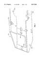
- FIG. 9shows the underside of the mated configuration of the first end effector 302 and the second end effector 502.
- Bolt holes 322a, 322b, 322c and 322d in the first end effector 302are provided for securing the first end effector 302 to the robot wrist.
- the bolt holes 322a, 322b, 322c and 322d(collectively, 322) comprise cylindrical bores cut into the handle portion 301 of the first end effector 302.
- the bolt holes 322are proportioned and positioned to couple to matching bolt holes on the top side of the robot wrist (not shown).
- FIG. 10depicts the substrate 108 being supported the edge grip pads 504 of the second end effector 502.
- the second end effector 502is equipped with vacuum pads 110a and 110b located on the top surface of each arm 506a and 506b, respectively, which create suction for gripping a substrate (not shown) to the substrate-holding area 512 of the second end effector 502.
- the vacuum pads 1110a and 1110bare coupled to a third vacuum line 320c to create the vacuum.
- FIG. 11ban alternative embodiment is shown in which the fingers 506a and 506b are joined in a bridge 1112 which is communicatively connected to the vacuum pad area 304 of the first end effector 302. Vacuum pads 1110a and 1110b are communicatively connected to the vacuum pad area 304 of the first end effector 302 via vacuum extension lines 1114 (shown in shadow). In this manner, the second end effector 502 may engage a substrate (not shown) using vacuum suction without requiring a third vacuum line.
- the present inventionprovides a method and apparatus for quickly and automatically changing from a first end effector for substrates of a first size to a mated configuration comprising a first end effector engaged with a second end effector.
- the robotrecognizes that a particular end effector is required when the robot receives a signal that a particular size substrate requires processing or that processing is to take place in a particular mode, such as ultra clean environment mode.
- a particular modesuch as ultra clean environment mode.
- the robotmay be programmed to switch to or from a mated configuration.
- the variation in pod size used for the respective substrate sizesmay trigger the robot to switch to or from a mated configuration, or the robot could be signaled via a manual switch.
- the robotIn order to utilize the mated configuration, the robot needs only retrieve the second end effector from a nest and lift the second end effector to couple atop the first end effector and further engage the second end effector to the first end effector by means of a vacuum seal, electromagnet, or any other latch.
- the second end effectormay be stored in the nest by reciprocal actions of the robot.
- an ultra clean semiconductor wafer positioning operationmight take 5 seconds. Clean mode positioning might be faster, taking only 3 seconds. Clean mode allows use of the vacuum to seal the substrate onto the end effector so the robot can move faster without causing misalignment of the substrate.
- the robotwill automatically select and mount the correct second large end effector for each batch of wafers. Furthermore, automated end effector change permits precise positioning operations to take place. For example, in the typical semiconductor wafer pod, wafers are narrowly spaced within the pod. The present invention permits precise handling operations to be performed on the narrowly spaced wafers.
Landscapes
- Engineering & Computer Science (AREA)
- Physics & Mathematics (AREA)
- Condensed Matter Physics & Semiconductors (AREA)
- General Physics & Mathematics (AREA)
- Manufacturing & Machinery (AREA)
- Computer Hardware Design (AREA)
- Microelectronics & Electronic Packaging (AREA)
- Power Engineering (AREA)
- Robotics (AREA)
- Container, Conveyance, Adherence, Positioning, Of Wafer (AREA)
Abstract
Description
Claims (17)
Priority Applications (2)
| Application Number | Priority Date | Filing Date | Title |
|---|---|---|---|
| US09/050,321US6077026A (en) | 1998-03-30 | 1998-03-30 | Programmable substrate support for a substrate positioning system |
| PCT/US1999/006685WO1999050891A1 (en) | 1998-03-30 | 1999-03-26 | A programmable substrate support for a substrate system |
Applications Claiming Priority (1)
| Application Number | Priority Date | Filing Date | Title |
|---|---|---|---|
| US09/050,321US6077026A (en) | 1998-03-30 | 1998-03-30 | Programmable substrate support for a substrate positioning system |
Publications (1)
| Publication Number | Publication Date |
|---|---|
| US6077026Atrue US6077026A (en) | 2000-06-20 |
Family
ID=21964586
Family Applications (1)
| Application Number | Title | Priority Date | Filing Date |
|---|---|---|---|
| US09/050,321Expired - Fee RelatedUS6077026A (en) | 1998-03-30 | 1998-03-30 | Programmable substrate support for a substrate positioning system |
Country Status (2)
| Country | Link |
|---|---|
| US (1) | US6077026A (en) |
| WO (1) | WO1999050891A1 (en) |
Cited By (29)
| Publication number | Priority date | Publication date | Assignee | Title |
|---|---|---|---|---|
| US6528767B2 (en) | 2001-05-22 | 2003-03-04 | Applied Materials, Inc. | Pre-heating and load lock pedestal material for high temperature CVD liquid crystal and flat panel display applications |
| US20030048455A1 (en)* | 2001-03-19 | 2003-03-13 | Fleming Timothy J. | Goniometer |
| US20030048448A1 (en)* | 2001-03-19 | 2003-03-13 | Fleming Timothy J. | Automated apparatus for testing optical filters |
| US20030059100A1 (en)* | 2001-03-19 | 2003-03-27 | Fleming Timothy J. | Method and apparatus for calibrating a vision system to a parts handling device |
| US6578893B2 (en) | 2000-10-02 | 2003-06-17 | Ajs Automation, Inc. | Apparatus and methods for handling semiconductor wafers |
| US6634686B2 (en) | 2001-10-03 | 2003-10-21 | Applied Materials, Inc. | End effector assembly |
| US20040113444A1 (en)* | 2002-12-17 | 2004-06-17 | Blonigan Wendell T. | End effector assembly |
| US6751882B1 (en)* | 2003-03-05 | 2004-06-22 | Kingpak Technology Inc. | Mechanism for positioning a substrate of an image sensor |
| US20040170407A1 (en)* | 2003-02-27 | 2004-09-02 | Applied Materials, Inc. | Substrate support |
| US20040226513A1 (en)* | 2003-05-12 | 2004-11-18 | Applied Materials, Inc. | Chamber for uniform heating of large area substrates |
| US20050036855A1 (en)* | 2003-08-13 | 2005-02-17 | Texas Instruments Incorporated | Robot blade for handling of semiconductor waffers |
| US6860027B2 (en)* | 2001-05-19 | 2005-03-01 | Wentworth Laboratories Limited | Wafer alignment device |
| US20050052041A1 (en)* | 2003-07-11 | 2005-03-10 | Bonora Anthony C. | Ultra low contact area end effector |
| US20050180737A1 (en)* | 2004-02-12 | 2005-08-18 | Applied Materials, Inc. | Substrate support bushing |
| US20050255244A1 (en)* | 2002-11-18 | 2005-11-17 | Applied Materials, Inc. | Lifting glass substrate without center lift pins |
| US20060005770A1 (en)* | 2004-07-09 | 2006-01-12 | Robin Tiner | Independently moving substrate supports |
| US20060249965A1 (en)* | 2002-12-19 | 2006-11-09 | Detlef Gerhard | Gripper and method for operating the same |
| US20070029227A1 (en)* | 2005-07-08 | 2007-02-08 | Bonora Anthony C | Workpiece support structures and apparatus for accessing same |
| US20070062454A1 (en)* | 2000-07-20 | 2007-03-22 | Applied Materials, Inc. | Method for dechucking a substrate |
| US20070094886A1 (en)* | 2005-10-04 | 2007-05-03 | Applied Materials, Inc. | Methods and apparatus for drying a substrate |
| US7374644B2 (en) | 2000-02-17 | 2008-05-20 | Applied Materials, Inc. | Conductive polishing article for electrochemical mechanical polishing |
| US20080131239A1 (en)* | 2006-11-15 | 2008-06-05 | Dynamic Micro Systems | Integrated gripper for workpiece transfer |
| US20080279659A1 (en)* | 2007-05-07 | 2008-11-13 | Lintec Corporation | Transferring device and transferring method |
| US20090314609A1 (en)* | 2008-06-18 | 2009-12-24 | Krakosh Iii Frank | Item-conveying device |
| US20100253106A1 (en)* | 2009-03-31 | 2010-10-07 | Ats Automation Tolling Systems Inc. | Vacuum gripper assembly |
| US20130102230A1 (en)* | 2010-06-30 | 2013-04-25 | Takafumi Komatsu | Method of Manufacturing Glass Substrate for Information Recording Medium, and Suction Instrument |
| US20150076849A1 (en)* | 2012-04-09 | 2015-03-19 | Semiconductor Technologies & Instruments Pte Ltd | End handler |
| US9754812B2 (en)* | 2015-02-22 | 2017-09-05 | Camtek Ltd. | Adaptable end effector |
| CN113140485A (en)* | 2021-03-31 | 2021-07-20 | 中国电子科技集团公司第十三研究所 | Wafer Cleaning Equipment |
Families Citing this family (3)
| Publication number | Priority date | Publication date | Assignee | Title |
|---|---|---|---|---|
| WO2001050503A1 (en)* | 1999-12-30 | 2001-07-12 | Speedfam-Ipec Corporation | Advanced wafer passive end-effector |
| CN105632971B (en) | 2014-11-26 | 2019-06-25 | 上海微电子装备(集团)股份有限公司 | A kind of silicon wafer processing unit and method |
| US10566230B2 (en) | 2016-04-01 | 2020-02-18 | Sunpower Corporation | Gripper for semiconductor devices |
Citations (6)
| Publication number | Priority date | Publication date | Assignee | Title |
|---|---|---|---|---|
| US4449885A (en)* | 1982-05-24 | 1984-05-22 | Varian Associates, Inc. | Wafer transfer system |
| US4971512A (en)* | 1987-12-18 | 1990-11-20 | Korea Electronics And Telecommunications Research Institute | Transport device for wafers of variable diameter |
| JPH04346247A (en)* | 1991-05-23 | 1992-12-02 | Fujitsu Ltd | Semiconductor manufacturing equipment, wafer transfer arm, and wafer mounting table |
| JPH0582625A (en)* | 1991-09-19 | 1993-04-02 | Hitachi Ltd | Wafer carrier |
| EP0609105A1 (en)* | 1993-01-29 | 1994-08-03 | Shin-Etsu Handotai Company Limited | Wafer cassette |
| JPH07201957A (en)* | 1993-12-29 | 1995-08-04 | Sony Corp | Wafer tape mounter |
- 1998
- 1998-03-30USUS09/050,321patent/US6077026A/ennot_activeExpired - Fee Related
- 1999
- 1999-03-26WOPCT/US1999/006685patent/WO1999050891A1/enactiveSearch and Examination
Patent Citations (6)
| Publication number | Priority date | Publication date | Assignee | Title |
|---|---|---|---|---|
| US4449885A (en)* | 1982-05-24 | 1984-05-22 | Varian Associates, Inc. | Wafer transfer system |
| US4971512A (en)* | 1987-12-18 | 1990-11-20 | Korea Electronics And Telecommunications Research Institute | Transport device for wafers of variable diameter |
| JPH04346247A (en)* | 1991-05-23 | 1992-12-02 | Fujitsu Ltd | Semiconductor manufacturing equipment, wafer transfer arm, and wafer mounting table |
| JPH0582625A (en)* | 1991-09-19 | 1993-04-02 | Hitachi Ltd | Wafer carrier |
| EP0609105A1 (en)* | 1993-01-29 | 1994-08-03 | Shin-Etsu Handotai Company Limited | Wafer cassette |
| JPH07201957A (en)* | 1993-12-29 | 1995-08-04 | Sony Corp | Wafer tape mounter |
Cited By (53)
| Publication number | Priority date | Publication date | Assignee | Title |
|---|---|---|---|---|
| US7374644B2 (en) | 2000-02-17 | 2008-05-20 | Applied Materials, Inc. | Conductive polishing article for electrochemical mechanical polishing |
| US20070062454A1 (en)* | 2000-07-20 | 2007-03-22 | Applied Materials, Inc. | Method for dechucking a substrate |
| US6578893B2 (en) | 2000-10-02 | 2003-06-17 | Ajs Automation, Inc. | Apparatus and methods for handling semiconductor wafers |
| US20030048455A1 (en)* | 2001-03-19 | 2003-03-13 | Fleming Timothy J. | Goniometer |
| US20030048448A1 (en)* | 2001-03-19 | 2003-03-13 | Fleming Timothy J. | Automated apparatus for testing optical filters |
| US20030059100A1 (en)* | 2001-03-19 | 2003-03-27 | Fleming Timothy J. | Method and apparatus for calibrating a vision system to a parts handling device |
| US6983547B2 (en) | 2001-03-19 | 2006-01-10 | Veeco Instruments Inc. | Goniometer |
| US7065892B2 (en) | 2001-03-19 | 2006-06-27 | Veeco Instruments Inc. | Method and apparatus for calibrating a vision system to a parts handling device |
| US6860027B2 (en)* | 2001-05-19 | 2005-03-01 | Wentworth Laboratories Limited | Wafer alignment device |
| US20030164362A1 (en)* | 2001-05-22 | 2003-09-04 | Applied Materials, Inc. | Pre-heating and loadlock pedestal material for high temperature CVD liquid crystal and flat panel display applications |
| US6924462B2 (en) | 2001-05-22 | 2005-08-02 | Applied Materials, Inc. | Pedestal for flat panel display applications |
| US6528767B2 (en) | 2001-05-22 | 2003-03-04 | Applied Materials, Inc. | Pre-heating and load lock pedestal material for high temperature CVD liquid crystal and flat panel display applications |
| US6634686B2 (en) | 2001-10-03 | 2003-10-21 | Applied Materials, Inc. | End effector assembly |
| US20050255244A1 (en)* | 2002-11-18 | 2005-11-17 | Applied Materials, Inc. | Lifting glass substrate without center lift pins |
| US20040113444A1 (en)* | 2002-12-17 | 2004-06-17 | Blonigan Wendell T. | End effector assembly |
| CN100446211C (en)* | 2002-12-17 | 2008-12-24 | 应用材料股份有限公司 | End effector assembly for supporting a substrate |
| US7641247B2 (en)* | 2002-12-17 | 2010-01-05 | Applied Materials, Inc. | End effector assembly for supporting a substrate |
| US7434856B2 (en)* | 2002-12-19 | 2008-10-14 | Icos Vision Systems N.V. | Gripper and method of operating the same |
| US20060249965A1 (en)* | 2002-12-19 | 2006-11-09 | Detlef Gerhard | Gripper and method for operating the same |
| US6917755B2 (en) | 2003-02-27 | 2005-07-12 | Applied Materials, Inc. | Substrate support |
| US20040170407A1 (en)* | 2003-02-27 | 2004-09-02 | Applied Materials, Inc. | Substrate support |
| US6751882B1 (en)* | 2003-03-05 | 2004-06-22 | Kingpak Technology Inc. | Mechanism for positioning a substrate of an image sensor |
| US20060169210A1 (en)* | 2003-05-12 | 2006-08-03 | Applied Materials, Inc. | Chamber for uniform heating of large area substrates |
| US20040226513A1 (en)* | 2003-05-12 | 2004-11-18 | Applied Materials, Inc. | Chamber for uniform heating of large area substrates |
| US7442900B2 (en) | 2003-05-12 | 2008-10-28 | Applied Materials, Inc. | Chamber for uniform heating of large area substrates |
| US20050052041A1 (en)* | 2003-07-11 | 2005-03-10 | Bonora Anthony C. | Ultra low contact area end effector |
| US7055875B2 (en) | 2003-07-11 | 2006-06-06 | Asyst Technologies, Inc. | Ultra low contact area end effector |
| US20050036855A1 (en)* | 2003-08-13 | 2005-02-17 | Texas Instruments Incorporated | Robot blade for handling of semiconductor waffers |
| US8216422B2 (en) | 2004-02-12 | 2012-07-10 | Applied Materials, Inc. | Substrate support bushing |
| US8033245B2 (en) | 2004-02-12 | 2011-10-11 | Applied Materials, Inc. | Substrate support bushing |
| US20050220604A1 (en)* | 2004-02-12 | 2005-10-06 | Applied Materials, Inc. | Substrate support bushing |
| US20050180737A1 (en)* | 2004-02-12 | 2005-08-18 | Applied Materials, Inc. | Substrate support bushing |
| US20060005770A1 (en)* | 2004-07-09 | 2006-01-12 | Robin Tiner | Independently moving substrate supports |
| US20070029227A1 (en)* | 2005-07-08 | 2007-02-08 | Bonora Anthony C | Workpiece support structures and apparatus for accessing same |
| US8800774B2 (en) | 2005-07-08 | 2014-08-12 | Brooks Automation, Inc. | Workpiece support structures and apparatus for accessing same |
| US20070094886A1 (en)* | 2005-10-04 | 2007-05-03 | Applied Materials, Inc. | Methods and apparatus for drying a substrate |
| US8635784B2 (en)* | 2005-10-04 | 2014-01-28 | Applied Materials, Inc. | Methods and apparatus for drying a substrate |
| US20080131239A1 (en)* | 2006-11-15 | 2008-06-05 | Dynamic Micro Systems | Integrated gripper for workpiece transfer |
| US8376428B2 (en)* | 2006-11-15 | 2013-02-19 | Dynamic Micro System Semiconductor Equipment GmbH | Integrated gripper for workpiece transfer |
| US9701024B2 (en)* | 2006-11-15 | 2017-07-11 | Brooks Ccs Gmbh | Integrated gripper for workpiece transfer |
| US8651539B1 (en) | 2006-11-15 | 2014-02-18 | Dynamic Micro System | Integrated gripper for workpiece transfer |
| US20140161572A1 (en)* | 2006-11-15 | 2014-06-12 | Dynamic Micro Systems, Semiconductor Equipment Gmb | Integrated gripper for workpiece transfer |
| US7875144B2 (en)* | 2007-05-07 | 2011-01-25 | Lintec Corporation | Transferring device and transferring method |
| US20080279659A1 (en)* | 2007-05-07 | 2008-11-13 | Lintec Corporation | Transferring device and transferring method |
| US20090314609A1 (en)* | 2008-06-18 | 2009-12-24 | Krakosh Iii Frank | Item-conveying device |
| US20100253106A1 (en)* | 2009-03-31 | 2010-10-07 | Ats Automation Tolling Systems Inc. | Vacuum gripper assembly |
| US8556315B2 (en)* | 2009-03-31 | 2013-10-15 | Ats Automation Tooling Systems Inc. | Vacuum gripper assembly |
| US20130102230A1 (en)* | 2010-06-30 | 2013-04-25 | Takafumi Komatsu | Method of Manufacturing Glass Substrate for Information Recording Medium, and Suction Instrument |
| JP2015516680A (en)* | 2012-04-09 | 2015-06-11 | セミコンダクター テクノロジーズ アンド インストゥルメンツ ピーティーイー リミテッド | End handler |
| US9524897B2 (en)* | 2012-04-09 | 2016-12-20 | Semiconductor Technologies & Instruments Pte Ltd | End handler for film and film frames and a method thereof |
| US20150076849A1 (en)* | 2012-04-09 | 2015-03-19 | Semiconductor Technologies & Instruments Pte Ltd | End handler |
| US9754812B2 (en)* | 2015-02-22 | 2017-09-05 | Camtek Ltd. | Adaptable end effector |
| CN113140485A (en)* | 2021-03-31 | 2021-07-20 | 中国电子科技集团公司第十三研究所 | Wafer Cleaning Equipment |
Also Published As
| Publication number | Publication date |
|---|---|
| WO1999050891A1 (en) | 1999-10-07 |
Similar Documents
| Publication | Publication Date | Title |
|---|---|---|
| US6077026A (en) | Programmable substrate support for a substrate positioning system | |
| CN114361086B (en) | Semiconductor process equipment and wafer transmission system thereof | |
| US4529353A (en) | Wafer handling apparatus and method | |
| US5664925A (en) | Batchloader for load lock | |
| US5692873A (en) | Apparatus for holding a piece of semiconductor | |
| US5609459A (en) | Door drive mechanisms for substrate carrier and load lock | |
| US5607276A (en) | Batchloader for substrate carrier on load lock | |
| US5613821A (en) | Cluster tool batchloader of substrate carrier | |
| US6517130B1 (en) | Self positioning vacuum chuck | |
| WO2022110484A1 (en) | Automatic assembly equipment for pcb and heat sinks of 3d printer | |
| KR102157427B1 (en) | Substrate transfer robot and substrate processing system | |
| US9701024B2 (en) | Integrated gripper for workpiece transfer | |
| KR101504796B1 (en) | Substrate transport hand and substrate transport robot | |
| EP1054439A1 (en) | Gripper for supporting substrate in a vertical orientation | |
| KR20150052329A (en) | Robot provided with end effector, and method for operating the robot | |
| US7052229B2 (en) | Alignment of semiconductor wafers and other articles | |
| KR100829769B1 (en) | Apparatus and method for arranging devices for processing | |
| CN112133657B (en) | Semiconductor processing equipment and method for transmitting wafer | |
| JP2025526016A (en) | End effector and robot having end effector | |
| CN115552583A (en) | Wafer transfer device and wafer transfer method | |
| CN119626970B (en) | Integrated wafer pre-adjustment part and wafer processing device | |
| US6572320B2 (en) | Robot for handling workpieces in an automated processing system | |
| US20040013503A1 (en) | Robotic hand with multi-wafer end effector | |
| JPS63131535A (en) | Substrate supporting device | |
| US20020036774A1 (en) | Apparatus and method for handling and testing of wafers |
Legal Events
| Date | Code | Title | Description |
|---|---|---|---|
| AS | Assignment | Owner name:PROGRESSIVE SYSTEM TECHNOLOGIES, INC., TEXAS Free format text:ASSIGNMENT OF ASSIGNORS INTEREST;ASSIGNOR:SHULTZ, RICHARD E.;REEL/FRAME:009078/0966 Effective date:19980330 | |
| AS | Assignment | Owner name:ASYST TECHNOLOGIES, INC., CALIFORNIA Free format text:AGREEMENT AND PLAN OF MERGER AND REORGANIZATION;ASSIGNOR:PROGRESSIVE SYSTEMS TECHNOLOGIES, INC.;REEL/FRAME:012145/0634 Effective date:19990602 | |
| FPAY | Fee payment | Year of fee payment:4 | |
| REFU | Refund | Free format text:REFUND - SURCHARGE, PETITION TO ACCEPT PYMT AFTER EXP, UNINTENTIONAL (ORIGINAL EVENT CODE: R2551); ENTITY STATUS OF PATENT OWNER: LARGE ENTITY | |
| SULP | Surcharge for late payment | ||
| FP | Lapsed due to failure to pay maintenance fee | Effective date:20040620 | |
| AS | Assignment | Owner name:BANK OF AMERICA, N.A., AS ADMINISTRATIVE AGENT,WAS Free format text:SECURITY AGREEMENT;ASSIGNORS:ASYST TECHNOLOGIES, INC.;ASYST JAPAN, INC.;REEL/FRAME:018303/0969 Effective date:20060713 Owner name:BANK OF AMERICA, N.A., AS ADMINISTRATIVE AGENT, WA Free format text:SECURITY AGREEMENT;ASSIGNORS:ASYST TECHNOLOGIES, INC.;ASYST JAPAN, INC.;REEL/FRAME:018303/0969 Effective date:20060713 | |
| REFU | Refund | Free format text:REFUND - 11.5 YR SURCHARGE - LATE PMT W/IN 6 MO, LARGE ENTITY (ORIGINAL EVENT CODE: R1556); ENTITY STATUS OF PATENT OWNER: LARGE ENTITY Free format text:REFUND - PAYMENT OF MAINTENANCE FEE UNDER 1.28(C) (ORIGINAL EVENT CODE: R1559); ENTITY STATUS OF PATENT OWNER: LARGE ENTITY | |
| AS | Assignment | Owner name:KEYBANK NATIONAL ASSOCIATION, AS ADMINISTRATIVE AG Free format text:SECURITY AGREEMENT;ASSIGNOR:ASYST TECHNOLOGIES, INC.;REEL/FRAME:019699/0165 Effective date:20070727 | |
| AS | Assignment | Owner name:ASYST TECHNOLOGIES, INC., CALIFORNIA Free format text:RELEASE BY SECURED PARTY;ASSIGNOR:BANK OF AMERICA, N.A., AS ADMINISTRATIVE AGENT;REEL/FRAME:019733/0967 Effective date:20070727 Owner name:ASYST JAPAN, INC., JAPAN Free format text:RELEASE BY SECURED PARTY;ASSIGNOR:BANK OF AMERICA, N.A., AS ADMINISTRATIVE AGENT;REEL/FRAME:019733/0967 Effective date:20070727 Owner name:ASYST TECHNOLOGIES, INC.,CALIFORNIA Free format text:RELEASE BY SECURED PARTY;ASSIGNOR:BANK OF AMERICA, N.A., AS ADMINISTRATIVE AGENT;REEL/FRAME:019733/0967 Effective date:20070727 Owner name:ASYST JAPAN, INC.,JAPAN Free format text:RELEASE BY SECURED PARTY;ASSIGNOR:BANK OF AMERICA, N.A., AS ADMINISTRATIVE AGENT;REEL/FRAME:019733/0967 Effective date:20070727 | |
| FEPP | Fee payment procedure | Free format text:PAT HOLDER NO LONGER CLAIMS SMALL ENTITY STATUS, ENTITY STATUS SET TO UNDISCOUNTED (ORIGINAL EVENT CODE: STOL); ENTITY STATUS OF PATENT OWNER: LARGE ENTITY Free format text:PAT HOLDER CLAIMS SMALL ENTITY STATUS, ENTITY STATUS SET TO SMALL (ORIGINAL EVENT CODE: LTOS); ENTITY STATUS OF PATENT OWNER: LARGE ENTITY | |
| REFU | Refund | Free format text:REFUND - PAYMENT OF MAINTENANCE FEE, 4TH YEAR, LARGE ENTITY (ORIGINAL EVENT CODE: R1551); ENTITY STATUS OF PATENT OWNER: LARGE ENTITY | |
| FPAY | Fee payment | Year of fee payment:8 | |
| SULP | Surcharge for late payment | Year of fee payment:7 | |
| ERR | Erratum | Free format text:IN THE NOTICE OF "PATENTS WHICH EXPIRED ON 20040620 DUE TO FAILURE TO PAY MAINTENANCE FEES" APPEARING IN THE OFFICIAL GAZETTE OF 20040817, ALL REFERENCE TO PATENT NO. 6077026 WHICH ISSUED FROM APPLICATION NO. 09/050321 SHOULD BE DELETED SINCE THE RELEVANT MAINTENANCE FEE WAS TIMELY PAID IN THAT PATENT. | |
| AS | Assignment | Owner name:CROSSING AUTOMATION, INC., CALIFORNIA Free format text:ASSET PURCHASE AGREEMENT-AFTER BANKRUPTCY;ASSIGNOR:ASYST TECHNOLOGIES, INC., AS DEBTOR AND DEBTOR IN POSSESSION;REEL/FRAME:026904/0827 Effective date:20090729 | |
| REMI | Maintenance fee reminder mailed | ||
| LAPS | Lapse for failure to pay maintenance fees | ||
| STCH | Information on status: patent discontinuation | Free format text:PATENT EXPIRED DUE TO NONPAYMENT OF MAINTENANCE FEES UNDER 37 CFR 1.362 | |
| FP | Lapsed due to failure to pay maintenance fee | Effective date:20120620 | |
| AS | Assignment | Owner name:BROOKS AUTOMATION US, LLC, MASSACHUSETTS Free format text:ASSIGNMENT OF ASSIGNORS INTEREST;ASSIGNOR:BROOKS AUTOMATION HOLDING, LLC;REEL/FRAME:058482/0001 Effective date:20211001 Owner name:BROOKS AUTOMATION HOLDING, LLC, MASSACHUSETTS Free format text:ASSIGNMENT OF ASSIGNORS INTEREST;ASSIGNOR:BROOKS AUTOMATION,INC;REEL/FRAME:058481/0740 Effective date:20211001 |