US6076892A - Multi-adjustable armrest assembly - Google Patents
Multi-adjustable armrest assemblyDownload PDFInfo
- Publication number
- US6076892A US6076892AUS08/868,678US86867897AUS6076892AUS 6076892 AUS6076892 AUS 6076892AUS 86867897 AUS86867897 AUS 86867897AUS 6076892 AUS6076892 AUS 6076892A
- Authority
- US
- United States
- Prior art keywords
- armrest
- collar
- grooves
- adjustable
- armrest assembly
- Prior art date
- Legal status (The legal status is an assumption and is not a legal conclusion. Google has not performed a legal analysis and makes no representation as to the accuracy of the status listed.)
- Expired - Fee Related
Links
- 230000007246mechanismEffects0.000claimsabstractdescription24
- 230000000717retained effectEffects0.000claimsdescription4
- 230000013011matingEffects0.000claimsdescription2
- 230000000712assemblyEffects0.000description4
- 238000000429assemblyMethods0.000description4
- 230000000694effectsEffects0.000description1
- 238000012986modificationMethods0.000description1
- 230000004048modificationEffects0.000description1
Images


Classifications
- A—HUMAN NECESSITIES
- A47—FURNITURE; DOMESTIC ARTICLES OR APPLIANCES; COFFEE MILLS; SPICE MILLS; SUCTION CLEANERS IN GENERAL
- A47C—CHAIRS; SOFAS; BEDS
- A47C1/00—Chairs adapted for special purposes
- A47C1/02—Reclining or easy chairs
- A47C1/022—Reclining or easy chairs having independently-adjustable supporting parts
- A47C1/03—Reclining or easy chairs having independently-adjustable supporting parts the parts being arm-rests
Definitions
- the present inventionrelates generally to armrests for chairs and more particularly, to an armrest assembly which is adjustable in a variety of aspects.
- adjustable office chairsare presently available.
- Such chairsmay, for example, include vertically adjustable seat height mechanisms, swivel tilt mechanisms, and adjustable back height mechanisms. Additionally, such chairs may be provided with adjustable armrest assemblies.
- Many such chairshave been provided which have an adjustable height armrest, such as U.S. Pat. No. 5,393,125 to Watson et al.
- Other such chairshave armrests which can be adjustable laterally to effect the spacing between the armrests, or armrests which can be rotated in towards the user or out away from the user. In most instances, such armrests are only adjustable in one of the particular aspects described above.
- a need exists for a multi-adjustable armrest assemblywhich provides for vertical height adjustment, lateral positioning, rotational positioning, and forwards and backwards positioning of the arm pad portion of the armrest assembly.
- Such a multi-adjustable armrestwhich provides positive adjustment in each of the aspects described can provide the widest possible variety of adjustable positions to accommodate users of different proportions and different tasks.
- the present inventionis directed to a multi-adjustable armrest assembly securable to a chair which can be adjusted in a wide variety of aspects for conveniently adapting to users of different proportions and also to comfortably accommodate various tasks performed while seated in the chair.
- An armrest assembly having features of the present inventioncan include a base securable to a chair and having a tubular portion, an armrest support having a vertical leg and a horizontal leg slidably disposed in the tubular portion, a shroud slidably disposed on the vertical leg, a post member attached to the shroud, a collar connected to the post, and an armrest connected to the collar. Additionally, the armrest can have a bottom portion slidably connected to the collar and the collar can be rotatably connected to the post.
- multi-adjustable arm assembliesIn the usual case, two such multi-adjustable arm assemblies will be provided with one assembly secured at either side of a chair.
- a multi-adjustable armrest assemblycan be adjustable in four different aspects.
- the horizontal legcan adjustably slide within the tubular portion of the base. This adjustment permits the armrest to be moved laterally in toward or out away from the chair.
- the spacing between the two armrest assemblies at either side of the chaircan be varied from a wide position to a narrow one according to the size of the person seated in the chair.
- each armrest assemblycan be adjusted independently of the other.
- the shroudcan be slidably disposed over the vertical leg of the armrest support so that the armrest can be moved up and down along the vertical leg. This adjustment permits the height of the each armrest to be varied according to the preference of the person seated in the chair.
- the bottom portion of the armrestcan slide with respect to the collar. This adjustment allows the armrest to be moved forwards and backwards relative to the armrest support so that the person seated in the chair can adjust the arm pad back and forth to find the most comfortable position.
- the post membercan be rotatably connected to the collar. This adjustment allows the armrest to be rotated about the vertical leg of the armrest support. Thus, the armrest can be rotated inwardly, towards the person seated in the chair, or outwardly, away from the person, and secured in a position which is most comfortable for the user.
- a positive adjustment mechanismcan preferably be provided to control each adjustable aspect described above.
- Each positive adjustment mechanismcan both lock the armrest in the desired position and release the armrest to permit it to be moved to a more comfortable position.
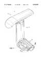
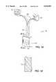
- FIG. 1is a perspective view of an embodiment of the invention
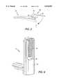
- FIG. 2is an exploded view of the lower portion of the embodiment shown in FIG. 1;
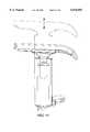
- FIG. 3is a partial cross section view taken along the line III--III;
- FIG. 4illustrates how the armrest assembly shown in FIG. 1 can move laterally
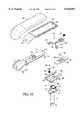
- FIG. 5is an exploded view of the middle portion of the embodiment shown in FIG. 1;
- FIG. 6is a perspective view of the opposite side of an embodiment of an armrest support shown in FIG. 2;
- FIG. 7is a perspective view of the opposite side of an embodiment of a shroud shown in FIG. 5;
- FIG. 8is a perspective view of an embodiment of an actuator
- FIG. 9is a rear plan view of the actuator shown in FIG. 8;
- FIG. 10is a partial cross section taken along the line X--X;
- FIG. 11illustrates how the armrest assembly shown in FIG. 1 can move vertically
- FIG. 12is an exploded view of an upper portion of the embodiment shown in FIG. 1;
- FIG. 13is an enlarged perspective view of a collar shown in FIG. 12;
- FIG. 14is a perspective view of the underside of the collar shown in FIG. 13;
- FIG. 15is an enlarged view of the top of an embodiment of a post shown in FIG. 12;
- FIG. 16illustrates how the armrest shown in FIG. 1 can rotate and move forwards and backwards
- FIG. 17is an enlarged perspective view of a bottom portion of the armrest shown in FIG. 13;
- FIG. 18is an enlarged perspective view of an embodiment of an actuator shown in FIG. 12.
- FIG. 19is a partial cross section of FIG. 18 taken along the line XIX--XIX.
- a multi-adjustable armrest assembly 10can include an armrest base 16 securable to a chair, an armrest support 14 having a vertical leg 20 and a horizontal leg 22 slidably connected to the armrest base 16, a shroud 44 slidably disposed on the vertical leg 20, a post 50 attached to the shroud 44, a collar 80 connected to the post 50, and an armrest 12 connected to the collar 80.
- the armrest 12can include a bottom portion 110 slidably connected to the collar 80.
- the collar 80can be rotatably connected to the post 50.
- the armrest base 16can include a mounting portion 30 which is attachable to the base of a chair by fasteners 33, which can be screws, and a tubular portion defined by an upwardly opening channel 32, a cover 40, and a clamping member 36.
- the channel 32, clamping member 36, and cover 40cooperate together to form a first positive adjustment mechanism to laterally adjust the armrest assembly 10 into and away from the chair in an infinite number of positions.
- the cover 40can have a generally cylindrical member 41 which is disposed in an arcuate shaped slot 29 in the underside of the mounting portion 30.
- the cover 40pivots about the axis, denoted by numeral 35, of the cylindrical member 41 in the slot 29 to cover the channel 32 thus enclosing the horizontal leg 22 therein.
- a stop means(not shown) can be provided to prevent the horizontal leg 22 from being completely removed from the channel 32.
- the cover 40extends over the channel 32, with the mounting portion 30 extending through the opening 43, and has an edge 42 which cooperates with the clamping member 36.
- a cam portion 39 of the clamping member 36is rotatably connected at a hinge 34 by pins 38 and is pivotable between a clamped position and an unclamped position.
- the cam portion 39can have the cross-section shown in FIG. 3.
- the horizontal leg 22is slidably positioned in the channel 32 when the clamping member 36 is in the unclamped position. In the clamped position, the cam portion 39 engages the edge 42 of the cover 40 and forces the cover 40 down against the horizontal leg 22 such that it can no longer slide in the channel 32.
- the clamped position of the clamp member 36 and the cover 40is shown in phantom lines in FIG. 3.
- a usergrasps the handle portion 37 and pulls upwardly.
- the cam portion 39pivots about the hinge 34 and releases the edge 42 into the unclamped position, thus releasing the cover 40 from its frictional engagement with the horizontal leg 22 so that it can slide freely in channel 32, into or away from the chair, as shown in FIG. 4.
- the usersimply swings the clamping member 36 downwardly into the clamped position.
- the cam portion 39pivots about the hinge 34 and urges the edge 42 of the cover 40 downwards such that the cover 42 is pressed against the horizontal leg 22 so that it can no longer slide in the channel 32.
- a shroud 44can be slidably disposed over the top of the vertical leg 20 of the armrest support 14.
- a post 50can be provided having a top end 51 and a lower end 54.
- the lower end 54is housed within the shroud 44 adjacent the vertical leg 20.
- the top end 51is attached to the top of the shroud 44 through holes 46 using fasteners 58.
- a second positive adjustment mechanism for vertically adjusting the height of the armrest 12can be formed from cooperating portions of a slide member 60, the lower end 54 of the post 50, and an outer surface 24 of the vertical leg 20 which is provided with a plurality of grooves 28 as shown in FIG. 6.
- the lower end 54 of the post 50can be positioned adjacent to the plurality of grooves 28 and can have a slot 56 provided therethrough.
- the slide member 60shown best in FIGS. 8 and 9, can include a lower lock plate portion 61 which has a pocket 62 provided therein positioned adjacent to the slot 56.
- a cylindrical pin 72can be provided in the slot 56 in communication with the pocket 62 on one side and the plurality of grooves 28 on the opposite side.
- the lock plate 61can move between an unlocked position and a locked position.
- the cylindrical pin 72In the locked position, the cylindrical pin 72 is retained by the lock plate 61 in one of the plurality of grooves 28 such that the shroud 44 is locked in place.
- the cylindrical pin 72In the unlocked position the cylindrical pin 72 is released into the pocket 62 of the lock plate 61 out of engagement with one of the plurality of grooves 28 so that the shroud 44 can slide upwardly and downwardly along the vertical leg 20, as shown in FIG. 11.
- the pocket 62can have a ramped profile 63, as shown in FIG. 10.
- the ramped profile 63rolls the cylindrical pin 72 into one of the plurality of grooves 28 whenever the lock plate 61 is moved to a locked position.
- the cylindrical pin 72is released into the pocket 62 and out of engagement with one of the plurality of grooves 28.
- a spring 70can be disposed in a channel 68, which can be seen best in FIG. 9, provided in the slide member 60 such that the spring 70 biases the lock plate 61 into a locked position.
- an externally accessible actuator 66shown in FIGS. 5 and 8, can be provided connected to the slide member 60 and cooperating with the lock plate 61 such that a person may pull upwards on the actuator 66 to unlock the lock plate 61 to adjust the height of the armrest 12 along the vertical leg 20. When the actuator 66 is released the spring 70 can urge the lock plate back into a locked position.
- An outer surface of the shroud 44can be provided with an opening 45, as shown in FIG. 7, so that the slide member 60 (which is housed within the shroud 44) and the actuator 66 can be accessible to the user.
- the outer surface 24 of the vertical leg 20can be provided with a recessed portion 26, shown in FIG. 6, wherein the lower end 54 of the post 50 and the slide member 60 can be disposed inside the shroud 44 and adjacent to the plurality of grooves 28.
- a stop member 64can be provided for preventing shroud 44 from being completely disengaged from the vertical leg 20.
- the stop member 64which can comprise a screw or fastener, passes through slide member 60, post 50 and is engaged with vertical leg 20.
- Shroud 44can include a matching stop catch (not shown) to mate with stop member 64 so as to prevent removal of the shroud 44 and the remainder of the armrest assembly from the vertical leg 20.
- the armrest 12can include an arm pad portion 130, a liner portion 132 and a bottom portion 110.
- the arm pad 130, liner 132, and bottom portion 110are connected to each other via holes 133, 135, 112, and 114 via fasteners 113 and 115.
- the bottom portion 110can be slidably connected to a collar 82 which can itself be rotatably connected to a top end 51 of the post 50.
- a third positive adjustment mechanismcan be provided for slidably adjusting the bottom portion 110 along the collar 80 to position the armrest 12 from front to back, as shown in FIG. 16. Similar to the second positive adjustment mechanism, the third positive adjustment mechanism utilizes a combination of a grooved surface, a cylindrical pin, and a pocketed locking member.
- the third positive adjustment mechanismcan be formed from cooperating portions of a fixed plate 96, the collar 80, and the bottom portion 110 of the armrest 12.
- the fixed plate 96can be provided with a plurality of grooves 98 in an upper surface thereof.
- the fixed plate 96can be received in a recess 89 in the collar 80. As shown best in FIGS. 12 and 13, arcuate portions 99 of the fixed plate 96 are received by and firmly held in the curved mating portions of the recess 89.
- the bottom portion 110can have a slot 118 therethrough which is adjacent to the plurality of grooves 98.
- the bottom portion 110can also have a pair of side rails 119 (opposite rail not shown) which can be slidably retained in a channel 82 between side portions 84 of the collar 80. Additionally, the bottom portion 110 can further include a Y-shaped channel 116 formed therein and a Y-shaped actuator 120 slidably disposed in the Y-shaped channel 116.
- the divergent legs 126 of the Y-shaped actuator 120are positioned in correspondingly shaped diverging portions of the Y-shaped channel and can have buttons 127 provided at ends thereof which extend beyond the edges of the bottom portion 110 so as to be externally accessible to operate the Y-shaped actuator 120.
- the Y-shaped actuator 120can also have a lock member 122 attached thereto, as shown in FIG. 18.
- the lock member 122can be provided with a pocket 123 adjacent the plurality of grooves 98.
- a second cylindrical pin 100can be disposed in the slot 118 in communication with the lock member 122 on one side and the plurality of grooves 98 on the other.
- the lock member 122is movable between a locked position and an unlocked position by the Y-shaped actuator 120.
- the lock member 122retains the second cylindrical pin 100 in one of the plurality of grooves 98 so that the pair of rails 119 of the bottom portion 110 cannot slide within the side portions 84 of the channel 82 in the collar 80.
- the second cylindrical pin 100is released from one of the plurality of grooves 98 into the pocket 123 so that the bottom portion 110 can freely slide in the channel 82 in the collar 80.
- the pocket 123can have a ramped profile 125 which rolls the second cylindrical pin 100 into one of the plurality of grooves 98 as the lock member 122 is moved to a locked position.
- a second spring 128can be provided for biasing the lock member 122 in a locked position.
- the spring 128is positioned in a channel 117 formed in the bottom portion 110 abutting the lock member 122.
- the externally accessible buttons 127are pressed towards each other causing the divergent legs 126 to move towards each other within the Y-shaped channel 116.
- the Y-shaped channel 116translates that movement into a lateral movement in which the single leg 124 of the Y-shaped member 120 moves the lock member 122 against the second spring 128 and into an unlocked position.
- a fourth positive adjustment mechanismfor permitting the armrest 12 to be rotated about the shroud 44 so that the user may position the armrest 12 in towards, or away from, the user.
- the fourth positive adjustment mechanismcan be formed from cooperating portions of the collar 80 and the post 50.
- the collar 80can have a lower cylindrical portion 88 having a plurality of radially spaced notches 81 provided on a bottom surface thereof.
- the post 50can have a top end 51 having a cylindrical edge in which can be provided a series of radially spaced teeth 52.
- the plurality of radially spaced teeth 52are firmly held in the plurality of radially spaced notches 81.
- the usercan grasp the armrest 12, lift upwardly, and rotate to the desired position. As the armrest 12 is lifted up the teeth 52 are lifted out of engagement with the notches 81 so the armrest 12 can freely rotate. When the desired amount of rotation is completed, the armrest 12 is released downwards so the teeth 52 once again are held in place in the notches 81.
- a spring 90can be provided to bias the collar 80 against the top end 51 of the post 50.
- a fastener 94 and a washer 92cooperate with the spring 90 to hold the collar 80 against the top end 51 of the post 50.
- the force of the spring 90 against the collar 80can be limited so that the user can lift up on the armrest 12 and overcome the spring force to disengage the teeth 52 from the notches 81 to permit the collar 80 to rotate on the top end 51 of the post 50 as described above.
- a pair of ribs 83 on an inside surface of the lower cylindrical portion 88can be provided to engage a pair of gaps 55 provided in the top end 51 in order to provide an overall limit to the degree of rotational movement. As the armrest 12 is rotated, the ribs 83 will eventually engage one of the gaps 55 and prevent further rotation beyond that point.
- the multi-adjustable armrest assemblyhaving features of the present invention thus permits for the armrest to be adjusted laterally in towards, or away from, the base of the chair, vertically up and down, forwards and backwards and also rotated in towards, or away from, the user. Moreover, in each instance the movement is precisely controlled by a positive adjustment mechanism.
Landscapes
- Health & Medical Sciences (AREA)
- Dentistry (AREA)
- General Health & Medical Sciences (AREA)
- Seats For Vehicles (AREA)
- Special Chairs (AREA)
Abstract
Description
Claims (16)
Priority Applications (3)
| Application Number | Priority Date | Filing Date | Title |
|---|---|---|---|
| US08/868,678US6076892A (en) | 1997-06-04 | 1997-06-04 | Multi-adjustable armrest assembly |
| CA002239365ACA2239365C (en) | 1997-06-04 | 1998-06-03 | Multi-adjustable armrest assembly |
| US09/404,740US6053578A (en) | 1997-06-04 | 1999-09-24 | Multi-adjustable armrest assembly |
Applications Claiming Priority (1)
| Application Number | Priority Date | Filing Date | Title |
|---|---|---|---|
| US08/868,678US6076892A (en) | 1997-06-04 | 1997-06-04 | Multi-adjustable armrest assembly |
Related Child Applications (1)
| Application Number | Title | Priority Date | Filing Date |
|---|---|---|---|
| US09/404,740ContinuationUS6053578A (en) | 1997-06-04 | 1999-09-24 | Multi-adjustable armrest assembly |
Publications (1)
| Publication Number | Publication Date |
|---|---|
| US6076892Atrue US6076892A (en) | 2000-06-20 |
Family
ID=25352134
Family Applications (2)
| Application Number | Title | Priority Date | Filing Date |
|---|---|---|---|
| US08/868,678Expired - Fee RelatedUS6076892A (en) | 1997-06-04 | 1997-06-04 | Multi-adjustable armrest assembly |
| US09/404,740Expired - LifetimeUS6053578A (en) | 1997-06-04 | 1999-09-24 | Multi-adjustable armrest assembly |
Family Applications After (1)
| Application Number | Title | Priority Date | Filing Date |
|---|---|---|---|
| US09/404,740Expired - LifetimeUS6053578A (en) | 1997-06-04 | 1999-09-24 | Multi-adjustable armrest assembly |
Country Status (2)
| Country | Link |
|---|---|
| US (2) | US6076892A (en) |
| CA (1) | CA2239365C (en) |
Cited By (77)
| Publication number | Priority date | Publication date | Assignee | Title |
|---|---|---|---|---|
| USD436259S1 (en) | 1999-11-08 | 2001-01-16 | Okamura Corporation | Chair |
| US6502904B1 (en)* | 1999-04-12 | 2003-01-07 | Sdm Hansen Ag | Arm support for a chair |
| USD469618S1 (en) | 2000-11-01 | 2003-02-04 | Okamura Corporation | Chair |
| USD476493S1 (en) | 2000-11-01 | 2003-07-01 | Okamura Corporation | Chair |
| USD476820S1 (en) | 2000-11-01 | 2003-07-08 | Okamura Corporation | Chair |
| US6637072B2 (en) | 2000-09-29 | 2003-10-28 | Formway Furniture Limited | Castored base for an office chair |
| EP1216632A3 (en)* | 2000-12-18 | 2003-11-05 | Kinnarps Ab | Adjustable armrest |
| GB2391800A (en)* | 2002-07-06 | 2004-02-18 | O & Es Mfg Ltd | Rotary, telescopic connector between a seatback and a seatbase |
| US6702386B2 (en) | 2001-06-15 | 2004-03-09 | Hon Technology Inc. | Height and pivot-adjustable chair arm |
| US20040046436A1 (en)* | 2001-01-25 | 2004-03-11 | Jsj Seating Company Texas, L.P. | Office chair |
| EP1405582A1 (en)* | 2002-10-04 | 2004-04-07 | Sedus Stoll AG | Arm-rest |
| US20040070251A1 (en)* | 2002-10-09 | 2004-04-15 | Lynn Roney | Chair with adjustable arms and/or back |
| US6733080B2 (en) | 1992-06-15 | 2004-05-11 | Herman Miller, Inc. | Seating structure having a backrest with a flexible membrane and a moveable armrest |
| US6773072B2 (en)* | 2001-06-15 | 2004-08-10 | Hon Technology Inc. | Vertically and horizontally adjustable chair armrest |
| US6802566B2 (en) | 2000-09-28 | 2004-10-12 | Formway Furniture Limited | Arm assembly for a chair |
| US20040206858A1 (en)* | 2001-06-19 | 2004-10-21 | Rockafellow Brent D | Adjustable armrest |
| US20040245835A1 (en)* | 1999-04-09 | 2004-12-09 | Niels Diffrient | Ergonomic armrest |
| WO2004106108A1 (en)* | 2003-05-28 | 2004-12-09 | Volvo Construction Equipment Holding Sweden Ab | Armrest for use with a vehicle seat |
| US6840582B2 (en) | 2002-05-14 | 2005-01-11 | Formway Furniture Limited | Height adjustable arm assembly |
| EP1457140A3 (en)* | 2003-03-13 | 2005-02-09 | Froli Kunststoffwerk Heinrich Fromme OHG | Arm support, particularly for office chairs and swivel chairs |
| US6908158B2 (en) | 2003-01-02 | 2005-06-21 | Haworth, Inc. | Lateral motion chair arm mechanism for chair arm |
| US20050189807A1 (en)* | 2004-02-27 | 2005-09-01 | Norman Christopher J. | Chair with functional armrest |
| USD509969S1 (en) | 2003-09-05 | 2005-09-27 | Steelcase Development Corporation | Seating unit |
| US20060226691A1 (en)* | 2005-04-08 | 2006-10-12 | Steelcase Development Corporation | Armrest with height adjustment mechanism |
| USD536890S1 (en) | 2004-03-03 | 2007-02-20 | Steelcase Development Corporation | Seating unit |
| US20070164594A1 (en)* | 2004-10-26 | 2007-07-19 | Ching-Chung Yang | Multi-functional armrest assembly |
| US20070200401A1 (en)* | 2006-02-27 | 2007-08-30 | Eberlein David C | Seating unit with adjustable components |
| US20080203818A1 (en)* | 2007-02-27 | 2008-08-28 | Kinpo Electronics, Inc. | Double power sources switching circuit |
| US20100213749A1 (en)* | 2009-02-25 | 2010-08-26 | Knoll, Inc. | Furniture and Method of Furniture Component Attachment |
| US20110018300A1 (en)* | 2009-07-27 | 2011-01-27 | Lear Corporation | Vehicle seating attachment assembly |
| US20110109145A1 (en)* | 2007-12-28 | 2011-05-12 | Jen Li-Wen | Armrest assembly |
| US8216416B2 (en) | 2008-06-06 | 2012-07-10 | Knoll, Inc. | Chair and method for assembling the chair |
| USD683150S1 (en) | 2012-09-20 | 2013-05-28 | Steelcase Inc. | Chair |
| USD683151S1 (en) | 2012-09-20 | 2013-05-28 | Steelcase Inc. | Chair |
| USD688499S1 (en) | 2012-09-20 | 2013-08-27 | Steelcase Inc. | Chair |
| USD688502S1 (en) | 2012-09-20 | 2013-08-27 | Steelcase Inc. | Arm assembly |
| USD688497S1 (en) | 2012-09-20 | 2013-08-27 | Steelcase Inc. | Chair |
| USD688907S1 (en) | 2012-09-20 | 2013-09-03 | Steelcase Inc. | Arm assembly |
| USD689319S1 (en) | 2012-09-20 | 2013-09-10 | Steelcase Inc. | Chair |
| USD689317S1 (en) | 2012-09-20 | 2013-09-10 | Steelcase Inc. | Chair |
| USD689314S1 (en) | 2012-09-20 | 2013-09-10 | Steelcase Inc. | Chair |
| USD690146S1 (en) | 2012-09-20 | 2013-09-24 | Steelcase Inc. | Chair |
| USD694538S1 (en) | 2012-09-20 | 2013-12-03 | Steelcase Inc. | Chair |
| USD694540S1 (en) | 2012-09-20 | 2013-12-03 | Steelcase Inc. | Chair |
| USD694537S1 (en) | 2012-09-20 | 2013-12-03 | Steelcase Inc. | Chair |
| USD697729S1 (en) | 2012-09-20 | 2014-01-21 | Steelcase Inc. | Chair |
| USD697730S1 (en) | 2012-09-20 | 2014-01-21 | Steelcase Inc. | Chair |
| USD697747S1 (en) | 2012-09-20 | 2014-01-21 | Steelcase Inc. | Chair |
| USD697726S1 (en) | 2012-09-20 | 2014-01-21 | Steelcase Inc. | Chair |
| USD698165S1 (en) | 2012-09-20 | 2014-01-28 | Steelcase Inc. | Chair |
| USD699957S1 (en) | 2012-09-20 | 2014-02-25 | Steelcase Inc. | Chair |
| USD703988S1 (en) | 2013-06-07 | 2014-05-06 | Steelcase Inc. | Chair |
| USD703987S1 (en) | 2013-06-07 | 2014-05-06 | Steelcase Inc. | Chair |
| USD704487S1 (en) | 2013-06-07 | 2014-05-13 | Steelcase Inc. | Chair |
| USD706547S1 (en) | 2013-06-07 | 2014-06-10 | Steelcase Inc. | Chair |
| USD707976S1 (en) | 2013-06-07 | 2014-07-01 | Steelcase Inc. | Chair |
| USD721529S1 (en) | 2013-06-07 | 2015-01-27 | Steelcase Inc. | Handle apparatus |
| US8998339B2 (en) | 2012-09-20 | 2015-04-07 | Steelcase Inc. | Chair assembly with upholstery covering |
| US9044098B2 (en) | 2012-11-16 | 2015-06-02 | Holland Plastics Corporation | Adjustable armrest assembly |
| WO2015157000A1 (en) | 2014-04-11 | 2015-10-15 | Knoll, Inc. | Armrest mechanism for a chair |
| US9320360B2 (en) | 2012-12-14 | 2016-04-26 | Holland Plastics Corporation | Armrest assembly |
| USD758774S1 (en) | 2015-04-24 | 2016-06-14 | Steelcase Inc. | Headrest assembly |
| USD759415S1 (en) | 2015-04-24 | 2016-06-21 | Steelcase Inc. | Headrest |
| USD760526S1 (en) | 2015-04-24 | 2016-07-05 | Steelcase Inc. | Headrest assembly |
| USD781605S1 (en) | 2015-04-24 | 2017-03-21 | Steelcase Inc. | Chair |
| USD781604S1 (en) | 2015-04-24 | 2017-03-21 | Steelcase Inc. | Chair |
| US10021984B2 (en) | 2015-04-13 | 2018-07-17 | Steelcase Inc. | Seating arrangement |
| US10194750B2 (en) | 2015-04-13 | 2019-02-05 | Steelcase Inc. | Seating arrangement |
| US10201465B2 (en)* | 2014-08-29 | 2019-02-12 | Panasonic Intellectual Property Management Co., Ltd. | Armrest locking mechanism and integrated bed having same |
| WO2019143516A1 (en) | 2018-01-22 | 2019-07-25 | Knoll, Inc. | Fastenerless arm pad attachment mechanism |
| US11229294B2 (en) | 2012-09-20 | 2022-01-25 | Steelcase Inc. | Chair assembly with upholstery covering |
| USD942767S1 (en) | 2012-09-20 | 2022-02-08 | Steelcase Inc. | Chair assembly |
| US11259637B2 (en) | 2015-04-13 | 2022-03-01 | Steelcase Inc. | Seating arrangement |
| US11304528B2 (en) | 2012-09-20 | 2022-04-19 | Steelcase Inc. | Chair assembly with upholstery covering |
| US20220194278A1 (en)* | 2020-12-21 | 2022-06-23 | Gugsoo An | Multi-joint driven console box for construction equipment |
| US11589678B2 (en) | 2019-01-17 | 2023-02-28 | Hni Technologies Inc. | Chairs including flexible frames |
| USD1063474S1 (en) | 2022-09-07 | 2025-02-25 | Steelcase Inc. | Chair |
Families Citing this family (31)
| Publication number | Priority date | Publication date | Assignee | Title |
|---|---|---|---|---|
| CA2371901A1 (en)* | 1999-06-17 | 2000-12-28 | Steelcase Inc. | Chair construction |
| DE20009574U1 (en)* | 2000-05-25 | 2000-08-10 | Bock-1 GmbH & Co., 92353 Postbauer-Heng | Chair, especially office chair |
| US6394553B1 (en) | 2000-06-09 | 2002-05-28 | Knoll, Inc. | Adjustable armrest assembly with single adjustment lever |
| IT1315480B1 (en)* | 2000-07-24 | 2003-02-18 | Plasticline Srl | ADJUSTABLE ARMREST FOR CHAIRS |
| CA2626453C (en)* | 2002-02-13 | 2011-02-01 | Herman Miller, Inc. | Tilt chair having a flexible back, adjustable armrests and adjustable seat depth, and methods for the use thereof |
| US6659561B1 (en)* | 2003-04-26 | 2003-12-09 | Hwang Pao Lee | Arm rest adjustable forwardly and rearwardly |
| US7210742B2 (en)* | 2005-03-22 | 2007-05-01 | Yao-Chuan Wu | Distance adjustment device for chair |
| US20060238004A1 (en)* | 2005-04-12 | 2006-10-26 | Conner John P | Modular seating system |
| US20060261659A1 (en)* | 2005-05-05 | 2006-11-23 | Dykes Tawana M | Adjustable arm and armrest assembly |
| US7452032B1 (en) | 2005-09-27 | 2008-11-18 | Earthlite Massage Tables, Inc. | Armrest assembly for a resting device |
| US7648207B2 (en)* | 2008-01-31 | 2010-01-19 | Yu-Shan Lai | Rotating structure for armrests |
| US8505186B2 (en)* | 2009-11-03 | 2013-08-13 | Knoll, Inc. | Method of fabricating a chair |
| USD652657S1 (en) | 2010-04-13 | 2012-01-24 | Herman Miller, Inc. | Chair |
| US8449037B2 (en) | 2010-04-13 | 2013-05-28 | Herman Miller, Inc. | Seating structure with a contoured flexible backrest |
| USD639091S1 (en) | 2010-04-13 | 2011-06-07 | Herman Miller, Inc. | Backrest |
| USD657166S1 (en) | 2010-04-13 | 2012-04-10 | Herman Miller, Inc. | Chair |
| USD637423S1 (en) | 2010-04-13 | 2011-05-10 | Herman Miller, Inc. | Chair |
| USD653061S1 (en) | 2010-04-13 | 2012-01-31 | Herman Miller, Inc. | Chair |
| USD650206S1 (en) | 2010-04-13 | 2011-12-13 | Herman Miller, Inc. | Chair |
| USD705134S1 (en) | 2012-07-26 | 2014-05-20 | Stryker Corporation | Wheelchair handlebars |
| US9943725B2 (en)* | 2012-11-27 | 2018-04-17 | Inertiacore Training Systems Llc | Exercise balance trainer |
| US9616285B2 (en)* | 2012-11-27 | 2017-04-11 | Inertiacore Training Systems Llc | Core exercise apparatus and methods |
| WO2014152550A2 (en) | 2013-03-15 | 2014-09-25 | Stryker Corporation | Medical support apparatus |
| USD727078S1 (en)* | 2013-08-12 | 2015-04-21 | Michael Chen | Arm rest cushion |
| US10080438B2 (en) | 2015-09-21 | 2018-09-25 | Stryker Corporation | Patient support apparatus |
| US11020295B2 (en) | 2015-12-22 | 2021-06-01 | Stryker Corporation | Patient support systems and methods for assisting caregivers with patient care |
| US10813806B2 (en) | 2016-05-24 | 2020-10-27 | Stryker Corporation | Medical support apparatus with stand assistance |
| US9848707B1 (en)* | 2016-07-28 | 2017-12-26 | Ergo-Industrial Seating Systems, Inc. | Telescoping mechanism |
| CA3176693A1 (en) | 2018-10-01 | 2020-04-01 | Melissa Fietz | Chair for supporting a person who is feeding a baby |
| NO347537B1 (en) | 2021-12-17 | 2023-12-18 | Flokk Sp Z O O | Armrest structure for a chair, and chair with armrest structure |
| NO20230162A1 (en) | 2023-02-17 | 2024-08-19 | Flokk Sp Z O O | Armrest structure for a chair, and chair with armrest structure |
Citations (21)
| Publication number | Priority date | Publication date | Assignee | Title |
|---|---|---|---|---|
| US3950027A (en)* | 1974-10-15 | 1976-04-13 | Sybron Corporation | Armrest for dental chair |
| US4456298A (en)* | 1980-10-15 | 1984-06-26 | Martin Stoll Gmbh | Apparatus for stepwise adjustment of separation between two chair portions |
| US4951995A (en)* | 1989-10-10 | 1990-08-28 | Steelcase Inc. | Arm height adjustment mechanism for a chair |
| US4961610A (en)* | 1989-08-21 | 1990-10-09 | Midmark Corporation | Clam shell armrest |
| US5050933A (en)* | 1990-07-02 | 1991-09-24 | Marta Tornero | Stacking chair with collapsible arms |
| US5056863A (en)* | 1989-10-10 | 1991-10-15 | Steelcase Inc. | Laterally adjustable armrest for a chair |
| US5143422A (en)* | 1991-04-22 | 1992-09-01 | Gerd Althofer | Adjustable active arm support for keyboard operators |
| US5265938A (en)* | 1991-12-05 | 1993-11-30 | Westinghouse Electric Corp. | Adjustable arm for a chair |
| US5324096A (en)* | 1992-03-02 | 1994-06-28 | Hon Industries Inc. | Adjustable height chair arm |
| US5338133A (en)* | 1993-03-05 | 1994-08-16 | Tornero Lino E | Lever clamp mechanism |
| US5346284A (en)* | 1992-09-10 | 1994-09-13 | Dauphin Entwicklungs- U. Beteiligungs-Gmbh | Seating furniture armrest |
| US5382079A (en)* | 1993-10-25 | 1995-01-17 | Chromcraft Revington, Inc. | Adjustable arm attachable to a chair body |
| US5393125A (en)* | 1993-05-28 | 1995-02-28 | Steelcase Inc. | Height adjustable chair arm assembly |
| US5393124A (en)* | 1992-12-08 | 1995-02-28 | Neil; Gary K. | Armrest assembly |
| US5439267A (en)* | 1993-05-28 | 1995-08-08 | Steelcase Inc. | Chair with adjustable arm assemblies |
| US5462338A (en)* | 1994-04-01 | 1995-10-31 | Krueger International, Inc. | Adjustable arm control |
| US5484187A (en)* | 1994-04-11 | 1996-01-16 | Doerner Products Ltd. | Chair armrest adjustment mechanism |
| US5655814A (en)* | 1996-03-07 | 1997-08-12 | Shin Yeh Enterprise Co., Ltd. | Adjustable chair-armrest assembly |
| US5660442A (en)* | 1994-08-15 | 1997-08-26 | Tornero; Lino E. | Adjusment device for chair arms |
| US5746480A (en)* | 1990-10-15 | 1998-05-05 | Bonutti; Peter M. | Armrest assembly |
| US5752683A (en)* | 1995-11-14 | 1998-05-19 | Global Upholstery Company | Arm support device |
- 1997
- 1997-06-04USUS08/868,678patent/US6076892A/ennot_activeExpired - Fee Related
- 1998
- 1998-06-03CACA002239365Apatent/CA2239365C/ennot_activeExpired - Fee Related
- 1999
- 1999-09-24USUS09/404,740patent/US6053578A/ennot_activeExpired - Lifetime
Patent Citations (21)
| Publication number | Priority date | Publication date | Assignee | Title |
|---|---|---|---|---|
| US3950027A (en)* | 1974-10-15 | 1976-04-13 | Sybron Corporation | Armrest for dental chair |
| US4456298A (en)* | 1980-10-15 | 1984-06-26 | Martin Stoll Gmbh | Apparatus for stepwise adjustment of separation between two chair portions |
| US4961610A (en)* | 1989-08-21 | 1990-10-09 | Midmark Corporation | Clam shell armrest |
| US4951995A (en)* | 1989-10-10 | 1990-08-28 | Steelcase Inc. | Arm height adjustment mechanism for a chair |
| US5056863A (en)* | 1989-10-10 | 1991-10-15 | Steelcase Inc. | Laterally adjustable armrest for a chair |
| US5050933A (en)* | 1990-07-02 | 1991-09-24 | Marta Tornero | Stacking chair with collapsible arms |
| US5746480A (en)* | 1990-10-15 | 1998-05-05 | Bonutti; Peter M. | Armrest assembly |
| US5143422A (en)* | 1991-04-22 | 1992-09-01 | Gerd Althofer | Adjustable active arm support for keyboard operators |
| US5265938A (en)* | 1991-12-05 | 1993-11-30 | Westinghouse Electric Corp. | Adjustable arm for a chair |
| US5324096A (en)* | 1992-03-02 | 1994-06-28 | Hon Industries Inc. | Adjustable height chair arm |
| US5346284A (en)* | 1992-09-10 | 1994-09-13 | Dauphin Entwicklungs- U. Beteiligungs-Gmbh | Seating furniture armrest |
| US5393124A (en)* | 1992-12-08 | 1995-02-28 | Neil; Gary K. | Armrest assembly |
| US5338133A (en)* | 1993-03-05 | 1994-08-16 | Tornero Lino E | Lever clamp mechanism |
| US5393125A (en)* | 1993-05-28 | 1995-02-28 | Steelcase Inc. | Height adjustable chair arm assembly |
| US5439267A (en)* | 1993-05-28 | 1995-08-08 | Steelcase Inc. | Chair with adjustable arm assemblies |
| US5382079A (en)* | 1993-10-25 | 1995-01-17 | Chromcraft Revington, Inc. | Adjustable arm attachable to a chair body |
| US5462338A (en)* | 1994-04-01 | 1995-10-31 | Krueger International, Inc. | Adjustable arm control |
| US5484187A (en)* | 1994-04-11 | 1996-01-16 | Doerner Products Ltd. | Chair armrest adjustment mechanism |
| US5660442A (en)* | 1994-08-15 | 1997-08-26 | Tornero; Lino E. | Adjusment device for chair arms |
| US5752683A (en)* | 1995-11-14 | 1998-05-19 | Global Upholstery Company | Arm support device |
| US5655814A (en)* | 1996-03-07 | 1997-08-12 | Shin Yeh Enterprise Co., Ltd. | Adjustable chair-armrest assembly |
Cited By (143)
| Publication number | Priority date | Publication date | Assignee | Title |
|---|---|---|---|---|
| US6733080B2 (en) | 1992-06-15 | 2004-05-11 | Herman Miller, Inc. | Seating structure having a backrest with a flexible membrane and a moveable armrest |
| US7475946B2 (en)* | 1999-04-09 | 2009-01-13 | Humanscale Corporation | Ergonomic armrest |
| US20040245835A1 (en)* | 1999-04-09 | 2004-12-09 | Niels Diffrient | Ergonomic armrest |
| US7980631B2 (en) | 1999-04-09 | 2011-07-19 | Humanscale Corporation | Ergonomic armrest |
| US20090091174A1 (en)* | 1999-04-09 | 2009-04-09 | Humanscale Corporation | Ergonomic Armrest |
| US6502904B1 (en)* | 1999-04-12 | 2003-01-07 | Sdm Hansen Ag | Arm support for a chair |
| USD436259S1 (en) | 1999-11-08 | 2001-01-16 | Okamura Corporation | Chair |
| US7798573B2 (en) | 2000-09-28 | 2010-09-21 | Formway Furniture Limited | Reclinable chair |
| US6908159B2 (en) | 2000-09-28 | 2005-06-21 | Formway Furniture Limited | Seat for a reclining office chair |
| US6874852B2 (en) | 2000-09-28 | 2005-04-05 | Formway Furniture Limited | Lumbar support |
| US6910741B2 (en) | 2000-09-28 | 2005-06-28 | Formway Furniture Limited | Lumbar support |
| US7441839B2 (en) | 2000-09-28 | 2008-10-28 | Formway Furniture Limited | Reclinable chair |
| US6802566B2 (en) | 2000-09-28 | 2004-10-12 | Formway Furniture Limited | Arm assembly for a chair |
| US6817667B2 (en) | 2000-09-28 | 2004-11-16 | Formway Furniture Limited | Reclinable chair |
| US6637072B2 (en) | 2000-09-29 | 2003-10-28 | Formway Furniture Limited | Castored base for an office chair |
| USD469618S1 (en) | 2000-11-01 | 2003-02-04 | Okamura Corporation | Chair |
| USD476493S1 (en) | 2000-11-01 | 2003-07-01 | Okamura Corporation | Chair |
| USD476820S1 (en) | 2000-11-01 | 2003-07-08 | Okamura Corporation | Chair |
| EP1216632A3 (en)* | 2000-12-18 | 2003-11-05 | Kinnarps Ab | Adjustable armrest |
| US20040046436A1 (en)* | 2001-01-25 | 2004-03-11 | Jsj Seating Company Texas, L.P. | Office chair |
| US7029071B2 (en)* | 2001-01-25 | 2006-04-18 | Jsj Seating Company Texas, L.P. | Office chair |
| US6773072B2 (en)* | 2001-06-15 | 2004-08-10 | Hon Technology Inc. | Vertically and horizontally adjustable chair armrest |
| US6702386B2 (en) | 2001-06-15 | 2004-03-09 | Hon Technology Inc. | Height and pivot-adjustable chair arm |
| US7029049B2 (en)* | 2001-06-19 | 2006-04-18 | Johnson Controls Technology Company | Adjustable armrest |
| US20040206858A1 (en)* | 2001-06-19 | 2004-10-21 | Rockafellow Brent D | Adjustable armrest |
| US6840582B2 (en) | 2002-05-14 | 2005-01-11 | Formway Furniture Limited | Height adjustable arm assembly |
| GB2391800A (en)* | 2002-07-06 | 2004-02-18 | O & Es Mfg Ltd | Rotary, telescopic connector between a seatback and a seatbase |
| US20040066080A1 (en)* | 2002-10-04 | 2004-04-08 | Sedus Stoll Ag | Armrest |
| US6948774B2 (en) | 2002-10-04 | 2005-09-27 | Sedus Stoll Ag | Armrest |
| CN100435694C (en)* | 2002-10-04 | 2008-11-26 | 塞杜斯.斯托尔股份公司 | Armrest |
| EP1405582A1 (en)* | 2002-10-04 | 2004-04-07 | Sedus Stoll AG | Arm-rest |
| US20040070251A1 (en)* | 2002-10-09 | 2004-04-15 | Lynn Roney | Chair with adjustable arms and/or back |
| US6908158B2 (en) | 2003-01-02 | 2005-06-21 | Haworth, Inc. | Lateral motion chair arm mechanism for chair arm |
| EP1457140A3 (en)* | 2003-03-13 | 2005-02-09 | Froli Kunststoffwerk Heinrich Fromme OHG | Arm support, particularly for office chairs and swivel chairs |
| US20060202541A1 (en)* | 2003-05-28 | 2006-09-14 | Volvo Construction Equipment Holding Sweden Ab | Armrest for use with a vehicle seat |
| WO2004106108A1 (en)* | 2003-05-28 | 2004-12-09 | Volvo Construction Equipment Holding Sweden Ab | Armrest for use with a vehicle seat |
| CN100509480C (en)* | 2003-05-28 | 2009-07-08 | 沃尔沃建造设备控股(瑞典)有限公司 | Armrest for vehicle seat |
| US7600819B2 (en) | 2003-05-28 | 2009-10-13 | Volvo Construction Equipment Ab | Armrest for use with a vehicle seat |
| USD534018S1 (en) | 2003-09-05 | 2006-12-26 | Steelcase Development Corporation | Control for seating unit |
| USD543397S1 (en) | 2003-09-05 | 2007-05-29 | Steelcase Development Corporation | Back construction |
| USD543396S1 (en) | 2003-09-05 | 2007-05-29 | Steelcase Development Corporation | Back construction |
| USD543385S1 (en) | 2003-09-05 | 2007-05-29 | Steelcase Development Corporation | Seat and back arrangement |
| USD534364S1 (en) | 2003-09-05 | 2007-01-02 | Steelcase Development Corporation | Seating unit having armrests |
| USD509969S1 (en) | 2003-09-05 | 2005-09-27 | Steelcase Development Corporation | Seating unit |
| US20050189807A1 (en)* | 2004-02-27 | 2005-09-01 | Norman Christopher J. | Chair with functional armrest |
| USD536890S1 (en) | 2004-03-03 | 2007-02-20 | Steelcase Development Corporation | Seating unit |
| US20070164594A1 (en)* | 2004-10-26 | 2007-07-19 | Ching-Chung Yang | Multi-functional armrest assembly |
| US20060238011A1 (en)* | 2005-04-08 | 2006-10-26 | Steelcase Development Corporation | Adjustable armrest with motion control |
| US7234779B2 (en) | 2005-04-08 | 2007-06-26 | Steelcase Development Corporation | Armrest with height adjustment mechanism |
| US7341313B2 (en) | 2005-04-08 | 2008-03-11 | Steelcase Development Corporation | Adjustable armrest with motion control |
| US20060226691A1 (en)* | 2005-04-08 | 2006-10-12 | Steelcase Development Corporation | Armrest with height adjustment mechanism |
| US20070200415A1 (en)* | 2006-02-27 | 2007-08-30 | Eberlein David C | Seating unit with adjustable components |
| US20070200401A1 (en)* | 2006-02-27 | 2007-08-30 | Eberlein David C | Seating unit with adjustable components |
| US7806481B2 (en) | 2006-02-27 | 2010-10-05 | Steelcase Inc. | Seating unit with adjustable components |
| US7527335B2 (en) | 2006-02-27 | 2009-05-05 | Steelcase Inc. | Seating unit with adjustable components |
| US20080203818A1 (en)* | 2007-02-27 | 2008-08-28 | Kinpo Electronics, Inc. | Double power sources switching circuit |
| US20110109145A1 (en)* | 2007-12-28 | 2011-05-12 | Jen Li-Wen | Armrest assembly |
| US8216416B2 (en) | 2008-06-06 | 2012-07-10 | Knoll, Inc. | Chair and method for assembling the chair |
| US20100213749A1 (en)* | 2009-02-25 | 2010-08-26 | Knoll, Inc. | Furniture and Method of Furniture Component Attachment |
| US8157329B2 (en) | 2009-02-25 | 2012-04-17 | Knoll, Inc. | Furniture and method of furniture component attachment |
| US20110018300A1 (en)* | 2009-07-27 | 2011-01-27 | Lear Corporation | Vehicle seating attachment assembly |
| USD689314S1 (en) | 2012-09-20 | 2013-09-10 | Steelcase Inc. | Chair |
| US10264889B2 (en) | 2012-09-20 | 2019-04-23 | Steelcase Inc. | Chair assembly with upholstery covering |
| USD688499S1 (en) | 2012-09-20 | 2013-08-27 | Steelcase Inc. | Chair |
| USD688502S1 (en) | 2012-09-20 | 2013-08-27 | Steelcase Inc. | Arm assembly |
| USD688497S1 (en) | 2012-09-20 | 2013-08-27 | Steelcase Inc. | Chair |
| USD688907S1 (en) | 2012-09-20 | 2013-09-03 | Steelcase Inc. | Arm assembly |
| USD689319S1 (en) | 2012-09-20 | 2013-09-10 | Steelcase Inc. | Chair |
| USD689317S1 (en) | 2012-09-20 | 2013-09-10 | Steelcase Inc. | Chair |
| USD689312S1 (en) | 2012-09-20 | 2013-09-10 | Steelcase Inc. | Chair |
| USD683150S1 (en) | 2012-09-20 | 2013-05-28 | Steelcase Inc. | Chair |
| USD689318S1 (en) | 2012-09-20 | 2013-09-10 | Steelcase Inc. | Chair |
| USD689313S1 (en) | 2012-09-20 | 2013-09-10 | Steelcase Inc. | Chair |
| USD689315S1 (en) | 2012-09-20 | 2013-09-10 | Steelcase Inc. | Arm assembly |
| USD690146S1 (en) | 2012-09-20 | 2013-09-24 | Steelcase Inc. | Chair |
| USD690547S1 (en) | 2012-09-20 | 2013-10-01 | Steelcase Inc. | Chair |
| USD694538S1 (en) | 2012-09-20 | 2013-12-03 | Steelcase Inc. | Chair |
| USD694540S1 (en) | 2012-09-20 | 2013-12-03 | Steelcase Inc. | Chair |
| USD694536S1 (en) | 2012-09-20 | 2013-12-03 | Steelcase Inc. | Chair |
| USD694537S1 (en) | 2012-09-20 | 2013-12-03 | Steelcase Inc. | Chair |
| USD694539S1 (en) | 2012-09-20 | 2013-12-03 | Steelcase Inc. | Chair |
| USD697729S1 (en) | 2012-09-20 | 2014-01-21 | Steelcase Inc. | Chair |
| USD697730S1 (en) | 2012-09-20 | 2014-01-21 | Steelcase Inc. | Chair |
| USD697747S1 (en) | 2012-09-20 | 2014-01-21 | Steelcase Inc. | Chair |
| USD697726S1 (en) | 2012-09-20 | 2014-01-21 | Steelcase Inc. | Chair |
| USD697727S1 (en) | 2012-09-20 | 2014-01-21 | Steeelcase Inc. | Chair |
| USD698166S1 (en) | 2012-09-20 | 2014-01-28 | Steelcase Inc. | Chair |
| USD698165S1 (en) | 2012-09-20 | 2014-01-28 | Steelcase Inc. | Chair |
| USD699061S1 (en) | 2012-09-20 | 2014-02-11 | Steelcase Inc. | Arm assembly |
| USD699957S1 (en) | 2012-09-20 | 2014-02-25 | Steelcase Inc. | Chair |
| USD699958S1 (en) | 2012-09-20 | 2014-02-25 | Steelcase Inc. | Chair |
| USD699959S1 (en) | 2012-09-20 | 2014-02-25 | Steelcase Inc. | Chair |
| USD701053S1 (en) | 2012-09-20 | 2014-03-18 | Steelcase Inc. | Chair |
| US12226028B2 (en) | 2012-09-20 | 2025-02-18 | Steelcase Inc. | Chair arm assembly |
| US11464341B2 (en) | 2012-09-20 | 2022-10-11 | Steelcase Inc. | Chair assembly with upholstery covering |
| US11304528B2 (en) | 2012-09-20 | 2022-04-19 | Steelcase Inc. | Chair assembly with upholstery covering |
| USD942767S1 (en) | 2012-09-20 | 2022-02-08 | Steelcase Inc. | Chair assembly |
| US11229294B2 (en) | 2012-09-20 | 2022-01-25 | Steelcase Inc. | Chair assembly with upholstery covering |
| US10842281B2 (en) | 2012-09-20 | 2020-11-24 | Steelcase Inc. | Control assembly for chair |
| US8967724B2 (en) | 2012-09-20 | 2015-03-03 | Steelcase Inc. | Chair arm assembly |
| US8998339B2 (en) | 2012-09-20 | 2015-04-07 | Steelcase Inc. | Chair assembly with upholstery covering |
| US9028001B2 (en) | 2012-09-20 | 2015-05-12 | Steelcase Inc. | Chair arm assembly |
| US10835041B2 (en) | 2012-09-20 | 2020-11-17 | Steelcase Inc. | Chair arm assembly |
| USD683151S1 (en) | 2012-09-20 | 2013-05-28 | Steelcase Inc. | Chair |
| USD742677S1 (en) | 2012-09-20 | 2015-11-10 | Steelcase Inc. | Chair |
| USD742676S1 (en) | 2012-09-20 | 2015-11-10 | Steelcase Inc. | Chair |
| US10213019B2 (en) | 2012-09-20 | 2019-02-26 | Steelcase Inc. | Chair arm assembly |
| US9872565B2 (en) | 2012-09-20 | 2018-01-23 | Steelcase Inc. | Chair arm assembly |
| US9826839B2 (en) | 2012-09-20 | 2017-11-28 | Steelcase Inc. | Chair assembly with upholstery covering |
| US9427085B2 (en) | 2012-09-20 | 2016-08-30 | Steelcase Inc. | Chair arm assembly |
| US9408467B2 (en) | 2012-09-20 | 2016-08-09 | Steelcase Inc. | Chair assembly with upholstery covering |
| US9044098B2 (en) | 2012-11-16 | 2015-06-02 | Holland Plastics Corporation | Adjustable armrest assembly |
| US9320360B2 (en) | 2012-12-14 | 2016-04-26 | Holland Plastics Corporation | Armrest assembly |
| USD703988S1 (en) | 2013-06-07 | 2014-05-06 | Steelcase Inc. | Chair |
| USD703987S1 (en) | 2013-06-07 | 2014-05-06 | Steelcase Inc. | Chair |
| USD704487S1 (en) | 2013-06-07 | 2014-05-13 | Steelcase Inc. | Chair |
| USD706547S1 (en) | 2013-06-07 | 2014-06-10 | Steelcase Inc. | Chair |
| USD707976S1 (en) | 2013-06-07 | 2014-07-01 | Steelcase Inc. | Chair |
| USD721529S1 (en) | 2013-06-07 | 2015-01-27 | Steelcase Inc. | Handle apparatus |
| US9861205B2 (en) | 2014-04-11 | 2018-01-09 | Knoll, Inc. | Armrest mechanism for a chair |
| US9351575B2 (en) | 2014-04-11 | 2016-05-31 | Knoll, Inc. | Armrest mechanism for a chair |
| WO2015157000A1 (en) | 2014-04-11 | 2015-10-15 | Knoll, Inc. | Armrest mechanism for a chair |
| US10201465B2 (en)* | 2014-08-29 | 2019-02-12 | Panasonic Intellectual Property Management Co., Ltd. | Armrest locking mechanism and integrated bed having same |
| US10194750B2 (en) | 2015-04-13 | 2019-02-05 | Steelcase Inc. | Seating arrangement |
| US11553797B2 (en) | 2015-04-13 | 2023-01-17 | Steelcase Inc. | Seating arrangement |
| US11963621B2 (en) | 2015-04-13 | 2024-04-23 | Steelcase Inc. | Seating arrangement |
| US11324325B2 (en) | 2015-04-13 | 2022-05-10 | Steelcase Inc. | Seating arrangement |
| US11259637B2 (en) | 2015-04-13 | 2022-03-01 | Steelcase Inc. | Seating arrangement |
| US11096497B2 (en) | 2015-04-13 | 2021-08-24 | Steelcase Inc. | Seating arrangement |
| US10021984B2 (en) | 2015-04-13 | 2018-07-17 | Steelcase Inc. | Seating arrangement |
| USD781605S1 (en) | 2015-04-24 | 2017-03-21 | Steelcase Inc. | Chair |
| USD759415S1 (en) | 2015-04-24 | 2016-06-21 | Steelcase Inc. | Headrest |
| USD781604S1 (en) | 2015-04-24 | 2017-03-21 | Steelcase Inc. | Chair |
| USD760526S1 (en) | 2015-04-24 | 2016-07-05 | Steelcase Inc. | Headrest assembly |
| USD758774S1 (en) | 2015-04-24 | 2016-06-14 | Steelcase Inc. | Headrest assembly |
| US10463155B2 (en) | 2018-01-22 | 2019-11-05 | Knoll, Inc. | Fastenerless arm pad attachment mechanism |
| WO2019143516A1 (en) | 2018-01-22 | 2019-07-25 | Knoll, Inc. | Fastenerless arm pad attachment mechanism |
| US11006759B2 (en) | 2018-01-22 | 2021-05-18 | Knoll, Inc. | Fastenerless arm pad attachment mechanism |
| US11589678B2 (en) | 2019-01-17 | 2023-02-28 | Hni Technologies Inc. | Chairs including flexible frames |
| US12075921B2 (en) | 2019-01-17 | 2024-09-03 | Hni Technologies Inc. | Chairs including flexible frames |
| US20220194278A1 (en)* | 2020-12-21 | 2022-06-23 | Gugsoo An | Multi-joint driven console box for construction equipment |
| US12077080B2 (en)* | 2020-12-21 | 2024-09-03 | Gugsoo An | Multi-joint driven console box for construction equipment |
| USD1063474S1 (en) | 2022-09-07 | 2025-02-25 | Steelcase Inc. | Chair |
Also Published As
| Publication number | Publication date |
|---|---|
| CA2239365A1 (en) | 1998-12-04 |
| US6053578A (en) | 2000-04-25 |
| CA2239365C (en) | 2005-03-22 |
Similar Documents
| Publication | Publication Date | Title |
|---|---|---|
| US6076892A (en) | Multi-adjustable armrest assembly | |
| US5324096A (en) | Adjustable height chair arm | |
| US4616877A (en) | Chair with back height adjustment | |
| CA2341342C (en) | Arm height adjustment mechanism for a chair | |
| CA1180655A (en) | Backrest height adjustment for office chair | |
| US6010189A (en) | Synchronized chair seat and backrest tilt control mechanism | |
| US6394553B1 (en) | Adjustable armrest assembly with single adjustment lever | |
| US5951102A (en) | High chair | |
| CA2357852C (en) | Arm assembly for a chair | |
| JP4543362B2 (en) | Seat furniture, especially the seat and back arrangement structure for office chairs | |
| CA2714892C (en) | Adjustable arm for chair | |
| US5104180A (en) | Folding and lock mechanism for baby chair | |
| US20020113475A1 (en) | Method for adjusting a seat | |
| US9861205B2 (en) | Armrest mechanism for a chair | |
| JPH0552726B2 (en) | ||
| US6533355B2 (en) | Height-adjustment mechanism for a chair | |
| EP0482439B1 (en) | Chair seat mounting mechanism | |
| CA1332146C (en) | Work chair or office chair | |
| KR100743935B1 (en) | Chair Armrest Adjuster | |
| EP0027419B1 (en) | Articulating headrest for dental chair | |
| JP3496139B2 (en) | Desk and chair leg height adjustment mechanism and its use | |
| JP2001029169A (en) | Chair support equipment | |
| CA2354507A1 (en) | Locking mechanism suitable for use in office type chairs | |
| JPH08182563A (en) | Mounting structure for control lever of chair | |
| JP3675145B2 (en) | Chair armrest device |
Legal Events
| Date | Code | Title | Description |
|---|---|---|---|
| AS | Assignment | Owner name:KNOLL, INC., PENNSYLVANIA Free format text:ASSIGNMENT OF ASSIGNORS INTEREST;ASSIGNORS:VAN HEKKEN, HENDRIK R.;CONLEY, CIRA V.;GARNER, MICHAEL S.;REEL/FRAME:008625/0827 Effective date:19970603 | |
| FPAY | Fee payment | Year of fee payment:4 | |
| AS | Assignment | Owner name:UBS AG, STAMFORD BRANCH, CONNECTICUT Free format text:SECURITY AGREEMENT;ASSIGNOR:KNOLL, INC.;REEL/FRAME:015215/0366 Effective date:20040929 | |
| AS | Assignment | Owner name:BANK OF AMERICA, N.A., ILLINOIS Free format text:ASSIGNMENT OF SECURITY AGREEMENT;ASSIGNOR:UBS AG, STAMFORD BRANCH;REEL/FRAME:016735/0753 Effective date:20051003 | |
| AS | Assignment | Owner name:KNOLL, INC., PENNSYLVANIA Free format text:TERMINATION OF SECURITY INTEREST;ASSIGNOR:BANK OF AMERICA, N.A., SUCCESSOR IN INTEREST TO UBS AG STAMFORD BRANCH;REEL/FRAME:019562/0191 Effective date:20070629 | |
| AS | Assignment | Owner name:BANK OF AMERICA, N.A., AS ADMINISTRATIVE AGENT, IL Free format text:NOTICE OF GRANT OF SECURITY INTEREST;ASSIGNOR:KNOLL, INC.;REEL/FRAME:019580/0808 Effective date:20070629 | |
| FPAY | Fee payment | Year of fee payment:8 | |
| REMI | Maintenance fee reminder mailed | ||
| LAPS | Lapse for failure to pay maintenance fees | ||
| STCH | Information on status: patent discontinuation | Free format text:PATENT EXPIRED DUE TO NONPAYMENT OF MAINTENANCE FEES UNDER 37 CFR 1.362 | |
| FP | Lapsed due to failure to pay maintenance fee | Effective date:20120620 | |
| AS | Assignment | Owner name:KNOLL, INC., PENNSYLVANIA Free format text:TERMINATION AND RELEASE OF SECURITY INTEREST IN PATENTS;ASSIGNOR:BANK OF AMERICA, N.A., AS ADMINISTRATIVE AGENT;REEL/FRAME:056990/0902 Effective date:20210719 Owner name:KNOLL, INC., PENNSYLVANIA Free format text:TERMINATION AND RELEASE OF SECURITY INTEREST IN PATENTS;ASSIGNOR:BANK OF AMERICA, N.A. (AS SUCCESSOR-BY-ASSIGNMENT TO UBS AG, STAMFORD BRANCH), AS ADMINISTRATIVE AGENT;REEL/FRAME:056990/0917 Effective date:20210719 |