US6076845A - Rear suspension for a bicycle having a flexible chain stay - Google Patents
Rear suspension for a bicycle having a flexible chain stayDownload PDFInfo
- Publication number
- US6076845A US6076845AUS09/160,001US16000198AUS6076845AUS 6076845 AUS6076845 AUS 6076845AUS 16000198 AUS16000198 AUS 16000198AUS 6076845 AUS6076845 AUS 6076845A
- Authority
- US
- United States
- Prior art keywords
- attachment point
- axle
- chain stay
- point
- pivot
- Prior art date
- Legal status (The legal status is an assumption and is not a legal conclusion. Google has not performed a legal analysis and makes no representation as to the accuracy of the status listed.)
- Expired - Fee Related
Links
- 239000000725suspensionSubstances0.000titleclaimsabstractdescription83
- 238000013016dampingMethods0.000claimsabstractdescription34
- 230000003213activating effectEffects0.000abstract1
- 239000002131composite materialSubstances0.000description6
- 230000007246mechanismEffects0.000description6
- 239000007787solidSubstances0.000description6
- OKTJSMMVPCPJKN-UHFFFAOYSA-NCarbonChemical compound[C]OKTJSMMVPCPJKN-UHFFFAOYSA-N0.000description4
- 229910052799carbonInorganic materials0.000description4
- 230000008859changeEffects0.000description3
- 230000006835compressionEffects0.000description3
- 238000007906compressionMethods0.000description3
- 239000004593EpoxySubstances0.000description2
- 229910052782aluminiumInorganic materials0.000description2
- XAGFODPZIPBFFR-UHFFFAOYSA-NaluminiumChemical compound[Al]XAGFODPZIPBFFR-UHFFFAOYSA-N0.000description2
- 230000008901benefitEffects0.000description2
- 238000006073displacement reactionMethods0.000description2
- 239000000463materialSubstances0.000description2
- 230000035939shockEffects0.000description2
- 229920000049Carbon (fiber)Polymers0.000description1
- FYYHWMGAXLPEAU-UHFFFAOYSA-NMagnesiumChemical compound[Mg]FYYHWMGAXLPEAU-UHFFFAOYSA-N0.000description1
- 238000010521absorption reactionMethods0.000description1
- 230000009471actionEffects0.000description1
- 230000004913activationEffects0.000description1
- 230000009286beneficial effectEffects0.000description1
- 239000004917carbon fiberSubstances0.000description1
- 238000006243chemical reactionMethods0.000description1
- 230000007423decreaseEffects0.000description1
- 230000001419dependent effectEffects0.000description1
- 230000000694effectsEffects0.000description1
- 229920006332epoxy adhesivePolymers0.000description1
- 230000003116impacting effectEffects0.000description1
- 229910052749magnesiumInorganic materials0.000description1
- 239000011777magnesiumSubstances0.000description1
- 229910052751metalInorganic materials0.000description1
- 239000002184metalSubstances0.000description1
- VNWKTOKETHGBQD-UHFFFAOYSA-NmethaneChemical compoundCVNWKTOKETHGBQD-UHFFFAOYSA-N0.000description1
- 230000004048modificationEffects0.000description1
- 238000012986modificationMethods0.000description1
- 239000011435rockSubstances0.000description1
- 239000003351stiffenerSubstances0.000description1
Images


Classifications
- B—PERFORMING OPERATIONS; TRANSPORTING
- B62—LAND VEHICLES FOR TRAVELLING OTHERWISE THAN ON RAILS
- B62K—CYCLES; CYCLE FRAMES; CYCLE STEERING DEVICES; RIDER-OPERATED TERMINAL CONTROLS SPECIALLY ADAPTED FOR CYCLES; CYCLE AXLE SUSPENSIONS; CYCLE SIDE-CARS, FORECARS, OR THE LIKE
- B62K25/00—Axle suspensions
- B62K25/04—Axle suspensions for mounting axles resiliently on cycle frame or fork
- B62K25/28—Axle suspensions for mounting axles resiliently on cycle frame or fork with pivoted chain-stay
- B62K25/30—Axle suspensions for mounting axles resiliently on cycle frame or fork with pivoted chain-stay pivoted on pedal crank shelf
Definitions
- This inventionrelates to bicycles, and more particularly relates to a new and improved rear suspension for a bicycle.
- Bicycle suspensionshave become popular because they allow riders to ride more comfortably over rough terrain, and with more control in difficult circumstances.
- Rear suspension systemsare particularly important in improving comfort and safety, and have been developed to the point of allowing more than 6" of vertical suspension travel of the rear wheel.
- the onset of downhill mountain bike racing in the early 1990'sprompted the design of rear suspensions having large amounts of suspension travel.
- the forward motive force generated by the rider through the drive trainis partially used to activate the suspension system.
- the partial activation of the rear suspensionreduces the efficiency with which the rider's pedaling energy is transmitted to the forward movement of the bicycle. While this phenomenon occurs in downhill style mountain bikes, it is not an important issue because of the particular downhill riding style.
- the energy loss phenomenonoccurs in a more general type of mountain bike, the resulting inefficiencies can drastically affect performance.
- the existing suspension systemsare relatively heavy in order to provide the desired strength and performance.
- the present inventionin general terms concerns a rear suspension system of a bicycle that efficiently transmits the pedal force to forward movement of the bicycle.
- the rear suspension system of the present inventionovercomes many of the aforementioned problems.
- the rear suspensionis energy-efficient, well balanced, and provides exceptional suspension travel, among other important advantages that are discussed below.
- the inventiongenerally includes a rear suspension bicycle having a rear wheel with an axle, a frame including a seat tube and a down tube having a top and bottom ends, a pair of drop link members, one for either side of the rear wheel, each having a top attachment point and a bottom attachment point, and an axle attachment point for receiving the axle.
- a seat stay assemblyis also included, having a front end and a rear end, and having a front pivot point adjacent the front end for pivotal attachment to the seat tube defining a first pivot point, and a pair of rear pivot points, each for pivotal attachment to the top attachment point of one of said drop link members, forming together the second pivot point.
- a chain stay assemblyis included, having a front end and a rear end, and defining a pair of pivot points at the rear end.
- the front of the chain stayis fixedly attached adjacent to the bottom end of the seat tube, and the pair of rear pivot points, each for pivotal attachment to the bottom attachment point of one of the drop link members, forms together the third pivot point.
- a damping elementis mounted between the seat stay assembly and the frame.
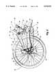
- FIG. 1is a side elevation view of a bicycle including the flexible chain stay of the present invention.
- FIG. 2is an enlarged side elevation view of a bicycle including the flexible chain stay of the present invention.
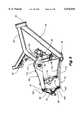
- FIG. 3is a side elevation view of a bicycle frame including the flexible chain stay of the present invention.
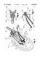
- FIG. 4is a side elevation view of the flexible chain stay of the present invention.
- FIG. 5is a front perspective view of a bicycle frame including the flexible chain stay.
- FIG. 6is a rear perspective view of the rear suspension system.
- FIG. 7is a rear perspective view of flexible chain stay.
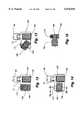
- FIG. 8is a section taken along line 8--8 of FIG. 7.
- FIG. 9is a section taken along line 9--9 of FIG. 2.
- FIG. 10is an enlarged side elevation of the rear suspension including the flexible chain stay showing the rear suspension in the compressed position in solid line and the rear suspension in uncompressed position in dash.
- FIG. 11is a front perspective view of a bicycle frame having a flexible chain stay with an adjustment mechanism attached thereto.
- FIG. 12is a section taken along line 12--12 of FIG. 11, showing the adjustment mechanism in a first position.
- FIG. 13is a representational section view similar to FIG. 12, wherein the adjustment mechanism is rotated from the first position.
- FIG. 14is a representational section view similar to FIG. 12, wherein the adjustment mechanism is rotated from the first position to a second position.
- FIG. 15is a section taken along line 15--15 of FIG. 14, and shows the attachment of the rear end of the adjustment mechanism, which is identical for the front end of the adjustment mechanism.
- FIG. 16is side elevation view of a bicycle frame where a rotary damper is used instead of a linear damper.
- a mountain bike 20which incorporates the rear suspension 22 of the present invention.
- the rear suspension 22 of the present inventioncan also be used on other types of bicycles, as well as motorcycles, but the preferred embodiment is described herein as used on a mountain bike.
- the mountain bikeincludes a frame 24 which rotatably supports a steering assembly 26.
- the steering assembly 26includes a handle bar 28 and fork 30.
- the forkreceives a front wheel 32 in a known manner, and also the handle bar, which allows the rider to steer the bicycle.
- the fork and handle barare rotatably received in a head tube 34 at the front end of the frame 24.
- the bicycle frame 24also includes a seat tube 36 for adjustably supporting a seat 38, and a down tube 40 extending from the head tube 34 to the bottom of the seat tube 36.
- the seat tubein some instances can be discontinuous, as shown here.
- a top tube 42extends from the head tube 34 to substantially the top of the seat tube 36. In instances where the seat tube is discontinuous, the top tube may have a forked end 44, as shown herein.
- a bottom bracket 46is attached to the frame 24 at the intersection of the seat tube 36 and the down tube 40, and rotatably supports the drive train 48.
- the drive train 48includes the chain ring(s) 50, crank arms 52 and pedals 54, all in a known manner.
- the rear suspension system 22 of the present inventionis attached to the frame 24 and generally extends rearwardly from the seat tube 36.
- the rear suspension system 22rotatably supports a rear wheel 56.
- the rear wheel 56includes a hub 58 having an axle 60 and a gear set 62 extending from one side concentric to the axle 60.
- the rear suspension system 22rotatably receives the axle 60 of the rear wheel 56 in a conventional manner.
- the drive train 48is completed with the connection of the chain ring 50 to the gear set 62 by a chain 64, and includes a derailleur system 66 which is controlled by the user to change gears on the front chain ring 50 as well as on the rear gear set 62.
- the rear suspension system 22is made up of four links attached together in a certain configuration, as defined below, to allow the rear wheel 56 of the mountain bike to move in a substantially vertical direction to absorb the shock from impacting objects such as rocks, stumps or the like.
- the rear suspension system 22includes a drop link assembly having one drop link 68, 70 for each side of the rear wheel 56 and hub 58, and each drop link includes a top 72 and bottom 74 attachment points, as well as an axle attachment point 76.
- a flexible chain stay assembly 78attaches at a front end 80 to the bottom bracket 46, and at the rear end 82 pivotally to the bottom attachment point 74 on each of the drop links 68 and 70.
- a seat stay assembly 84pivotally attaches to the seat tube 36 adjacent its front end 86, between a point midway up the seat tube 36 from the bottom bracket 46, and at its rear end 88 to the top attachment point 72 of each of the drop links 68, 70.
- a damper arm 90extends forwardly from the seat stay 84 assembly to receive one end 92 of a damper assembly 94.
- the other end 96 of the damper assembly 94is mounted to the frame 24, preferably adjacent to the bottom of the seat tube 36. It is contemplated that the damper 94 can be positioned elsewhere on the bicycle 20, such as between the seat stay 84 and the frame 24, between the chain stay 78 and the frame 24, or between the chain stay 78 and the seat stay 84.
- the damper 94acts to absorb energy in compression and rebound of the suspension movement (see FIG. 10).
- A. suitable linear damper 94is the Super Deluxe model available from Rockshox.
- a rotary damper 94'can also be used at the intersection of the seat stay 84 and the seat tube 36 to replace the linear dampers mentioned above.
- the rotary dampersimilar to those used on motorcycles, such as the Kayaba Rotary Damper sold on the Suzuki TL 1000 motorcycle, acts to damp the motion in the movement of the pivot point between the seat tube 36 and the seat stay 84.
- the rear suspension assembly 22is designed such that when the rider actuates the drive train by pedaling, which creates a force through the chain 64 on the rear suspension system, the rear suspension 22 does not appreciably compress or in other ways actuate, and thus efficiently transfers the rider's energy into forward movement of the bicycle 20.
- the combination flex-pivotal link system of the rear suspension system 22inhibits the actuation of the suspension travel due to the forces; in the drive train 48 from pedaling, and thus efficiently transfers the pedaling force efficiently to the forward motion of the bicycle. This force balancing is created by the location of the pivots in the rear suspension 22.
- the combination flex-pivot system of the rear suspension system 22allows the rear wheel 56 to move in a substantially upward direction.
- the force of the impactis partially absorbed by actuating the damping member 94 through the movement of the damping arm 90, and by the flexible chain stay assembly.
- the flexible chain stayreturns the rear wheel to the pre-impact position.
- each drop link 68 or 70is positioned on either side of the rear wheel 56, and each one is a substantial mirror image of the other.
- Each drop link 68 or 70has a substantially triangular shape, with the top attachment point 72, bottom attachment point 74, and axle attachment point 76 forming the three points of the triangle.
- the top attachment point 72is approximately 4.125 inches from the axle attachment point 76
- the bottom attachment point 74is approximately 3.4 inches from the axle attachment point 76.
- the line between the axle attachment point 76 and the top attachment point 72, and the line between the axle attachment point 76 and the bottom attachment point 74form an angle of approximately 83°.
- each drop link 68, 70makes them very strong and rigid, which allows them to efficiently transfer any movement or force to the other members of the rear suspension system 22 to which each drop link is attached.
- Each drop link 68, 70can be a solid piece of plate metal, or can have apertures formed therethrough for weight saving. Suitable materials for making the drop links include forged or extruded aluminum, magnesium, or carbon composite.
- drop links 68, 70 used in the present inventionare as described above, it is contemplated that the drop links could be of any shape or pivot location and still provide the beneficial effects of the flexible chain stay 78 of the present invention.
- the drop links 68, 70could have a substantially linear alignment of the pivot points, be curvilinear in shape, or extend up the seat stay 84 toward the seat tube 38, or along the flexible chain stay 78 toward the seat tube 36.
- each drop linkis oriented in the non-compressed stage such that the top attachment point 72 is upwardly and forwardly from the axle attachment point 76, and the bottom attachment point 74 is forwardly and downwardly positioned from the axle attachment point 76, and the bottom attachment point 74 is forwardly and downwardly positioned from the top attachment point 72.
- the axle attachment point 76defines a downwardly opening recess for receiving an end of the axle 60 in a conventional manner.
- the side 98 of the drop link 68 between the axle attachment point 76 and the bottom attachment point 74forms an inwardly directed curve to allow the derailleur 66 to freely move as required to change gears and rotate to take up chain slack.
- the top attachment point 72 of the drop linkincludes a slot 100 defined by co-extending flanges 102 for receiving the seat stay assembly 84, as is described further below.
- An apertureis formed through both flanges 102 to allow a pivotal connection to be made pivotally with the seat stay assembly 84.
- the bottom attachment point 74has a similar slot 104 to the top attachment point 72 for receiving the rear end of the chain stay assembly 84.
- a disc brake caliper 106is attached to the left side (per convention) drop link 70 to engage the disc 108 mounted to the left side (also per convention) of the hub 58 of the rear wheel.
- the disc brake caliper 106is actuated in a normal fashion by a brake lever on the handlebars.
- the axle 60 of the rear wheel 56is attached to the drop links 68, 70 in the axle attachment point 76 in a normal manner, such as by a quick release fastener 110.
- the seat stay assembly 84defines a solid central portion 112 having a pair of legs 114 extending rearwardly from the central portion, each leg extending along the side of the rear wheel 56.
- the solid central portion 112pivotally attaches to the seat tube 36 to form the first pivot point 116, such as by a rod and bearing 118 extending through an aperture in the central portion 112.
- This pivotal connection between the seat stay 84 and the seat tube 36is in the range of approximately 5 inches to 12 inches above the rotational center of the bottom bracket 46.
- the first pivot 116is 8.25 inches vertically above the center of the bottom bracket 36 and along the line from horizontal.
- An acceptable rangeis from 5-12 inches vertically above the bottom bracket 36, and 4 inches or less on either side of, and measured normal to, the line.
- a pair of legs 120extend forwardly from the solid central portion 112 and extend around the sides of the seat tube 36 and form the damping arm.
- each of the distal ends of the rearwardly extending legs 114is received in the top connection point 72 of one of the drop link 68 or 70.
- a second pivotal connection 122is formed between the distal end of each of the legs 114 of the seat stay 84 assembly and the top attachment point 72 of the drop link 68, 70 by a screw 124 received in a pin 126, with the pin engaging a bearing 128 inserted in the aperture formed through the end of the leg.
- the second pivot 122is preferably 4.125 inches from the axle at an angle of 65° above the horizontal.
- the position of the second pivot 122is related to the first pivot 116.
- the second pivot 122can be horizontally in-line with the first pivot and displaced downwardly, up to the amount of the total suspension displacement, such as up to approximately 6 inches. If the second pivot 122 is much lower than the amount of suspension displacement from the first pivot 116, energy efficiency decreases.
- the fore/aft position of the second pivot 122 with respect to the first pivot 116is not as important as its vertical relationship with the first pivot 116.
- the two legs 120 that extend forwardly of the central solid portion 112 of the seat stay 84define the damper arm.
- the ends of these legs 120pivotally attach to a damping member 94 on either side of a top end 94 thereof
- the damping member 94extends at an angle downwardly from the line between the first 116 and second pivot 122 points.
- the damping member 94is mounted preferably at an angle of approximately 60 degrees between the line defined between the first pivot point 116 and the pivot point at the end of the damping arm 90, and the line defined by the axis of the damping member 94 itself when at rest.
- This anglechanges as the damping member 94 is actuated since the damping member 94 is pivotally mounted at its base to the bottom bracket 46 and rotates about that point when actuated.
- the effectiveness of the damping member 94is controlled by the angle at which the damping arm 120 extends from the seat stay 84, the length of the damping arm 90, the type of damping member 94, and the attachment position of the bottom end 96 of the damping member 94.
- the damping arm 90is pivotally attached to the top end 92 of the damping member 24, with the bottom end 96 of the damping member 94 attached to the seat tube 36 near the intersection of the seat tube 36 and the down tube 40, or to the bottom bracket 46.
- a bracket 126can be attached to the seat tube 36 and supported on the down tube 40 to pivotally attach to the bottom end 96 of the damping member 94.
- a suitable damping member 94is the Super Deluxe model available from the Rockshox company.
- the damping arm 90is forced in a downwardly direction, thus actuating the damping member 94. It is contemplated that the damping member 94 can be repositioned behind the seat tube 36 and activated off of the seat stay 84. Also, a pull-damper could be used with the appropriate structural modifications.
- the seat stay 84extends rearwardly and downwardly from the first pivot point 116 to the second pivot point 122.
- the seat stay 84is preferably made of carbon/epoxy composite or aluminum, with each leg 114 of the seat stay 84 having a substantially rectangular cross section to minimize any flexure in the vertical or lateral direction along its length.
- the seat stay 84is stiff in the vertical and horizontal directions to compensate for any independent flexure of the sides of the chain stay 78.
- the damper-arm 90may not be required if the damping member is positioned elsewhere on the bicycle from. However, preferably, the seat stay 84 actuates the damping member 94.
- the chain stay assembly 78is a substantially U-shaped member defining opposing legs 130 extending rearwardly from the base 132, or cross brace, of the U shape, one leg each for extending along each side of the rear wheel 56.
- the chain stayis preferably made of a carbon fiber epoxy composite.
- the chain stay 78has a front end and a rear end, the front end defining the cross-brace for fixed attachment to the bottom bracket 46.
- the bottom bracket 46defines rearwardly extending spaced flanges 134 for receiving the front portion of the cross-brace 132.
- the flanges 134 and cross-brace 132are fixedly attached together by any known means, such as by bolts or rivets 136 passing through each flange 134 and the cross-brace 132, as shown in FIG. 8.
- the fastenersare preferably releasable or replaceable to allow the chain stay member 78 to be replaced.
- the cross-brace 32provides torsional stiffness to the opposing legs 130 extending therefrom.
- the chain stay 78is designed by the selection of the composite and structure (e.g. cross-sectional shape) to provide adequate lateral stiffness.
- the bottom bracket 46can form a collar defining a recess for receiving the cross brace instead of preferred spaced flanges. The connection between the bottom bracket 46 and the front end of the chain stay creates the fixed anchor for the chain stay and its vertical spring action.
- Each of the legs 130 of the chain stay 78are preferably rectangular in cross section, being wider at the front end and can taper to a minimum dimension at the rear or opposing end. The thickness dimension does not change drastically from the front end to the rear end.
- the shape of the legs 130can be any suitable shape providing sufficient vertical flexibility and lateral stability.
- the legs 130also diverge as they extend from their front end to their rear end.
- the legs of the chain stay 78are each vertically tunable springs (depending on carbon layup and/or structure), and can be tuned to make chain stays 78 of different vertical stiffness and thus amplitude of movement under a given force.
- each of the legs of the chain stay assembly 78is positioned in a slot 138 formed in the chain stay end boss 140, or connector member.
- the chain stay end boss 140is then attached to the bottom attachment point 74 of the particular drop link 68 or 70, and is preferably pivotally attached thereto in any known manner.
- One such manneris by a screw 142 received in a pin 144, with the pin engaging a bearing 146 inserted in the aperture formed through the end of the leg 130, as shown in FIG. 9.
- the chain stay end boss 140defines the channel 138 for receiving the rear ends of the legs 130 of the chain stay 78.
- the slot 138can open inwardly, as shown in FIG. 9, or outwardly.
- the chain stay end boss 140can be co-molded onto the chain stay 78 when the chain stay is formed, or can be bonded to the composite with an epoxy adhesive. This provides for mechanical attachment of the chain stay end boss 140 to the chain stay legs 130.
- the chain stay 78is fixedly attached at the front end to the bottom bracket 46, and is pivotally attached to the drop link 68, 70.
- the chain stay 78flexes along its length.
- the front end of the chain stayis fixed and the rear end moves in a curvilinear path upwardly.
- This vertical flexing of the chain stay 78generates the spring force (reaction force) to move the suspension from the compressed position back to the uncompressed position (See FIG. 10).
- the vertical stiffness of the chain stay 78is adjustable depending on the carbon layup and physical dimensions of the chain stay 78.
- Each of the extending legs 130 of the flexible chain stayare stabilized against torsion or independent flexing by the laterally rigid connection through the drop links 68 and 70 to the rigid seat stay 84.
- the bottom bracket 46attaches to the front end of the chain stay 78 in a horizontal line drawn through the rotational center of the bottom bracket.
- the rotational center of the bottom bracket 46is a convenient reference point, and is the center of rotation of the crank arms as supported in the bottom bracket.
- the position of the attachment between the bottom bracket 46 and the front end of the chain stay 78can range from directly above the bottom bracket by two inches to directly below the bottom bracket by two inches, or any position between along a rearward arc. Its position is limited to the rear by the rear tire, and forwardly by the bottom bracket and front derailleur position.
- the third pivot 148is the pivotal connection between the end of the chain stay 78 and the bottom attachment point 74 of the drop link 68 or 70.
- the proper position of the third pivot 148is dependent upon the position of the chain stay attachment point 72.
- the third pivot 148could be horizontally even with, or below the chain stay attachment point 72.
- the fore/aft position of the third pivotdepends on the clearance with the rear derailleur. Other placement considerations include the particular spacing requirements preferred by the derailleur manufacturer, which can be modified to some extent without drastically affecting derailleur performance.
- the first pivot point 116is defined as the pivot point formed between the seat stay 84 and the seat tube 36.
- the second pivot point 122is defined as the pivot point formed between the seat stay 84 and the top attachment point 72 of the drop link 68.
- the third pivot point 148is defined as the pivotal connection between the rear end of the chain stay 78 and the bottom attachment point 74 of the drop link 68.
- the entire set of pivot locations and flexible chain stayis a complex relationship that composes the suspension system 22.
- Some important characteristics with respect to the rear suspension systeminclude the axle path, leverage ratio, wheel rate, and energy efficiency.
- Each of the pivots and the flexible chain stayhave a different degree to which they affect the performance of these characteristics.
- Energy efficiencyrelates to the tendency of the suspension to compress, or otherwise actuate, due to the pedaling forces transmitted by the chain to the suspension system, which causes the suspension system to move, and thus use energy that could otherwise move the bike forward.
- the damping member 94is actuated by the seat stay 84 and resists the movement.
- the spring characteristic inherent in the flexing of the chain stay 78resists the upward movement of the suspension to provide additional shock absorption.
- the energy stored in the chain stay 78 due to its flexingis then released to move the rear suspension downwardly from the compressed position to the uncompressed position.
- the suspension 22is limited in moving substantially past the uncompressed position downwardly by the damping member 94.
- the spring constant (stiffness) of the flexible chain stay 78can be modified by changing its material, its cross section shape (oval, square, rectangular, circular, etc.), or the length of the flexible portion of the legs (i.e., the front, or other portion, of the chain stay can be relatively stiff or even rigid). This would typically require that the chain stay be removed and replaced with the another chain stay 78 having the desired flexing characteristics.
- stiffness adjusting structure 158can be added to a flexible chain stay 78 to allow for the adjustment of the flexing characteristics without changing the actual chain stay. See FIGS. 11-15.
- One embodiment of the means for varying the stiffness of the chain stay 78includes a rotatable auxiliary rod 160 mounted at its ends to the chain stay 78, and positioned along side each leg of the chain stay. The rod would extend a significant length along each leg 130.
- the auxiliary rod 160has a cross sectional shape selected to be stiffer in one rotational position (FIG. 12) than another (such as a rectangular or oval cross sectional shape). See FIG. 14. The auxiliary rod 160 is thus rotated so the cross sectional shape is oriented in the desired direction, and fixed in that position, to provide the additional stiffness characteristics.
- the stiffness adjusting structure 158(identical on each leg 130) is shown in FIGS. 11-15.
- the auxiliary rod 160has a front end 162 rotatably received in a first boss 164, and a rear end 166 rotatably received in a second boss 168.
- a jam screw 170(FIG. 15) is positioned in each boss to hold the auxiliary rod in the desired rotational position as selected by the user. The jam screw 170 loosens to allow the rod 160 to turn in the first and second bosses. The rotational position of the rod is thus fixed in the bosses by the jam screw, and thus it is fixed relative to the chain stay 78 also.
- the rod 160is shown as having a rectangular cross section between the front 182 and rear 166 ends. When the long dimension is oriented vertically, as in FIG. 12, the rod enhances the stiffness of the legs 130 a relatively larger amount than when the long dimension is oriented horizontally, as in FIG. 14.
- FIG. 13shows the rod in an intermediate position. While the jam screw works, other means of releasably fixing the rotation of the rod are acceptable.
- the front boss 164can be integrally formed with the bottom bracket 46.
- the rear boss 168can be integrally formed with the chain stay end boss 140'.
- the instant inventionincludes a four-bar rear suspension 22 with three rigid members (links) and one flexible member, all attached by three pivot points and one fixed junction.
- the flexible memberis fixed at one end to one of the rigid links, and pivotally attached at its other end to another of the rigid links.
- the third rigid linkis pivotally attached at each opposing end to one of the other rigid links.
- the flexible member, the chain stayflexes upwardly and stores energy when the suspension is compressed, and rebounds downwardly and expends energy when uncompressed from the compressed position.
- the damperacts to further provide energy absorbency.
- the flexible memberhas a spring rate that can be modified by the structure of the flexible member itself, or it can be modified by adding on an adjustable stiffener, as described above.
- An important benefit of the present inventionis that it allows for a relatively lighter bicycle.
- the flexible chain stayacts to absorb more energy than chain stays of available rear suspensions, and thus allows the seat stay to be designed more weight-efficiently since it does not have to absorb as much energy.
- the strong bottom bracket structure of the frameis the anchor point for the flexible chain stay, thus allowing the front triangle of the frame to be designed more weight-efficiently.
- the damperdoes not require a heavy coil spring.
- the combination of the composite chain stay, lighter seat stay, lighter front triangle and no coil springprovides significant weight saving.
Landscapes
- Engineering & Computer Science (AREA)
- Mechanical Engineering (AREA)
- Axle Suspensions And Sidecars For Cycles (AREA)
Abstract
Description
Claims (13)
Priority Applications (1)
| Application Number | Priority Date | Filing Date | Title |
|---|---|---|---|
| US09/160,001US6076845A (en) | 1998-09-24 | 1998-09-24 | Rear suspension for a bicycle having a flexible chain stay |
Applications Claiming Priority (1)
| Application Number | Priority Date | Filing Date | Title |
|---|---|---|---|
| US09/160,001US6076845A (en) | 1998-09-24 | 1998-09-24 | Rear suspension for a bicycle having a flexible chain stay |
Publications (1)
| Publication Number | Publication Date |
|---|---|
| US6076845Atrue US6076845A (en) | 2000-06-20 |
Family
ID=22575051
Family Applications (1)
| Application Number | Title | Priority Date | Filing Date |
|---|---|---|---|
| US09/160,001Expired - Fee RelatedUS6076845A (en) | 1998-09-24 | 1998-09-24 | Rear suspension for a bicycle having a flexible chain stay |
Country Status (1)
| Country | Link |
|---|---|
| US (1) | US6076845A (en) |
Cited By (45)
| Publication number | Priority date | Publication date | Assignee | Title |
|---|---|---|---|---|
| US6170845B1 (en)* | 1999-06-09 | 2001-01-09 | Merida Industry Co., Ltd. | Bicycle frame |
| US6244610B1 (en)* | 1996-10-28 | 2001-06-12 | Klaus Kramer-Massow | Two wheeled vehicle, especially a bicycle |
| WO2001087697A1 (en)* | 2000-05-16 | 2001-11-22 | Cannondale Corporation | Living hinge member and suspension |
| US20020144850A1 (en)* | 2001-04-04 | 2002-10-10 | Kazuhiko Gogo | Rear suspension attaching structure of motorcycle |
| DE10115603A1 (en)* | 2001-03-29 | 2002-10-17 | Iko Sportartikel Handels Gmbh | Cycle frame has damping device anchored on two saddle tube supports through transverse stay assembly for better stability |
| US20030107516A1 (en)* | 1997-04-16 | 2003-06-12 | Karl-Heinz Hansmann | Electronic distress call and position finding system for rescuing distressed people |
| US6595310B2 (en)* | 2000-09-05 | 2003-07-22 | Honda Giken Kogyo Kabushiki Kaisha | Swing arm type suspension for vehicles |
| US20030205882A1 (en)* | 2001-05-16 | 2003-11-06 | Parkin Michael James | Living hinge member and suspension |
| USD485788S1 (en) | 2002-02-23 | 2004-01-27 | Bombardier Inc. | Three-wheeled vehicle |
| US20040070169A1 (en)* | 2001-03-01 | 2004-04-15 | Philippe Lesage | Rear suspension of a vehicle with drive wheel borne by an oscillating arm |
| US20040069073A1 (en)* | 2002-10-11 | 2004-04-15 | Miller Larry D. | Anti-bob system for cycles |
| US20050018793A1 (en)* | 2003-07-24 | 2005-01-27 | Learned Rachel E. | Hybrid turbo-mud for multiple access systems |
| US20050046145A1 (en)* | 2002-04-15 | 2005-03-03 | Chamberlain Jason L. | Frame assembly for a bicycle |
| US6910702B1 (en)* | 1999-06-04 | 2005-06-28 | Cato Hals | All-suspension bicycle frame with isolated drive gear |
| USD508442S1 (en)* | 2004-07-06 | 2005-08-16 | Shimano Inc. | Bicycle chain stay |
| US20060033306A1 (en)* | 2004-08-11 | 2006-02-16 | Sanchez Steve E | Multi-bar linkage suspension system |
| US20060071442A1 (en)* | 2004-09-15 | 2006-04-06 | Yeti Cycling, Llc | Rear suspension system for a bicycle |
| US20060137928A1 (en)* | 2004-12-29 | 2006-06-29 | Parker James G | Rear suspension for a motorcycle |
| USD533237S1 (en) | 2004-07-29 | 2006-12-05 | Saris Cycling Group, Inc. | Frame for a cycling exerciser |
| US20090001685A1 (en)* | 2007-06-29 | 2009-01-01 | Specialized Bicycle Components, Inc. | Bicycle frame |
| US20090026728A1 (en)* | 2007-07-27 | 2009-01-29 | Niner, Inc. | Bicycle rear suspension |
| USD593457S1 (en) | 2007-06-29 | 2009-06-02 | Specialized Bicycle Components, Inc. | Bicycle frame |
| US20090261556A1 (en)* | 2008-04-17 | 2009-10-22 | Sotto Llc | Bicycle Rear Suspension System Linkage |
| DE102008025689A1 (en) | 2008-05-29 | 2009-12-10 | Iko Sportartikel-Handels-Gmbh | Bicycle frame, has front wheel frame including rocker that is rotatable around rocker axle, damping device shifted to rear supporting axle and connected with rocker, and supporting axle running ahead of rocker opposite to rocker axle |
| USD635062S1 (en)* | 2010-03-22 | 2011-03-29 | Joseph Savola | Chain catcher |
| US20110233892A1 (en)* | 2007-07-27 | 2011-09-29 | Niner, Inc. | Bicycle Rear Suspension |
| US8201841B2 (en) | 2009-07-21 | 2012-06-19 | Sotto Group, Llc | Bicycle rear suspension linkage |
| US20130300085A1 (en)* | 2012-05-08 | 2013-11-14 | DIAMANT S.r.I. | Bicycle frame |
| USD694156S1 (en)* | 2011-11-15 | 2013-11-26 | Bike Concept Oy | Bicycle |
| US8857841B2 (en) | 2011-01-05 | 2014-10-14 | Trek Bicycle Corporation | Bicycle frame with passive seat tube pivot joint |
| US8882127B2 (en) | 2007-04-16 | 2014-11-11 | Trek Bicycle Corporation | Bicycle rear wheel suspension system |
| US9056647B2 (en)* | 2013-08-22 | 2015-06-16 | Samuel Hu | One-piece connector for a shock-absorbing frame of a bicycle |
| US9359039B2 (en) | 2013-12-23 | 2016-06-07 | Wayne Lumpkin | Bicycle frame rear suspension with flexing frame segment |
| US9561834B2 (en) | 2010-08-20 | 2017-02-07 | Yeti Cycling, Llc | Link suspension system |
| US9821879B2 (en) | 2010-08-20 | 2017-11-21 | Yeti Cycling, Llc | Reciprocating rail movement suspension system |
| US10086899B2 (en) | 2015-05-17 | 2018-10-02 | Trek Bicycle Corporation | Adjustable compliance bicycle |
| US10766563B2 (en) | 2013-01-16 | 2020-09-08 | Yeti Cyclying, Llc | Rail suspension with integral shock and dampening mechanism |
| USD908542S1 (en) | 2019-07-19 | 2021-01-26 | Cycling Sports Group, Inc. | Bicycle flex stay |
| US10926830B2 (en) | 2017-07-07 | 2021-02-23 | Yeti Cycling, Llc | Vehicle suspension linkage |
| US11173983B2 (en) | 2017-03-17 | 2021-11-16 | Yeti Cycling, Llc | Vehicle suspension linkage |
| USD958702S1 (en) | 2020-08-05 | 2022-07-26 | Specialized Bicycle Components, Inc. | Bicycle frame |
| IT202100024426A1 (en)* | 2021-09-23 | 2023-03-23 | Star Due S R L | SUSPENSION FOR BICYCLES |
| US12077241B2 (en) | 2019-02-01 | 2024-09-03 | Yeti Cycling, Llc | Multi-body vehicle suspension linkage |
| US12145684B2 (en) | 2019-12-24 | 2024-11-19 | Yeti Cycling, Llc | Constrained multiple instantaneous velocity center linkage assembly for vehicle suspension |
| US12384484B2 (en) | 2020-11-18 | 2025-08-12 | Yeti Cycling, Llc | Integrated motor mount and suspension pivot |
Citations (35)
| Publication number | Priority date | Publication date | Assignee | Title |
|---|---|---|---|---|
| US452073A (en)* | 1891-05-12 | Bicycle | ||
| US644788A (en)* | 1899-09-05 | 1900-03-06 | Gurdon H Williams | Framework for bicycles. |
| US707262A (en)* | 1902-01-18 | 1902-08-19 | James H Sager | Cushion-frame for bicycles or like vehicles. |
| US709718A (en)* | 1901-09-20 | 1902-09-23 | Robert Franklin Monahan | Bicycle-frame. |
| US1029771A (en)* | 1911-07-03 | 1912-06-18 | Charles G Stephenson | Spring-frame for motor-cycles. |
| US1261440A (en)* | 1916-07-08 | 1918-04-02 | George Edwin Rigby | Spring-frame for cycles and motor-cycles. |
| FR753260A (en)* | 1933-03-30 | 1933-10-12 | Rear suspension for bicycles, motorcycles and motor bicycles | |
| FR884138A (en)* | 1942-07-10 | 1943-08-03 | Improvements to the suspension of bicycles | |
| FR996586A (en)* | 1945-04-25 | 1951-12-21 | Elastic frame for cycle | |
| US3917313A (en)* | 1973-12-17 | 1975-11-04 | Bultaco Compania Espanola Espa | Motorcycle suspension system |
| US3982770A (en)* | 1974-09-12 | 1976-09-28 | Yamaha, Hatsudoki Kabushiki Kaisha | Bicycle suspension |
| US4058181A (en)* | 1976-03-16 | 1977-11-15 | Buell Erik F | Motorcycle suspension systems |
| US4114918A (en)* | 1977-03-18 | 1978-09-19 | Parlec, Inc. | Suspension system for wheel of a motor bike |
| US4789174A (en)* | 1987-04-27 | 1988-12-06 | Mert Lawwill | Suspension bicycle |
| US5098114A (en)* | 1990-09-18 | 1992-03-24 | Jones Gwyndaf M | Pivotless human-powered vehicle suspension system |
| US5121937A (en)* | 1990-12-13 | 1992-06-16 | Mert Lawwill | Suspension bicycle |
| US5205572A (en)* | 1991-08-27 | 1993-04-27 | Schwinn Bicycle Company | Cycle rear suspension system |
| US5217241A (en)* | 1990-09-18 | 1993-06-08 | Ocean State International Inc. | Bicycle suspension system |
| US5226674A (en)* | 1991-08-27 | 1993-07-13 | Schwinn Bicycle Company | Cycle rear suspension system |
| US5244224A (en)* | 1992-05-14 | 1993-09-14 | Gt Bicycles, Inc. | Rocker arm rear suspension bicycle |
| US5259637A (en)* | 1993-01-13 | 1993-11-09 | Gt Bicycles, Inc. | Bicycle rear suspension |
| US5301974A (en)* | 1989-04-18 | 1994-04-12 | Knapp Engineering | Bicycle suspension system |
| US5316327A (en)* | 1993-04-15 | 1994-05-31 | Bell James H | Chainless bicycle with dual drive shafts and floating drive train suspension system |
| US5332246A (en)* | 1992-06-15 | 1994-07-26 | Buell Motor Company, Inc. | Single sided cycle rear suspension system with vertical wheel mounting means |
| US5335929A (en)* | 1992-06-17 | 1994-08-09 | Miyata Industry Co., Ltd. | Bicycle frame |
| US5354085A (en)* | 1990-12-21 | 1994-10-11 | Otto Gally | Sprung bicycle |
| US5409249A (en)* | 1993-09-15 | 1995-04-25 | Gt Bicycles, Inc. | Bicycle rear suspension system |
| US5413368A (en)* | 1993-09-16 | 1995-05-09 | Cannondale Corporation | Bicycle with trailing arm wheel suspensions |
| US5452910A (en)* | 1994-09-09 | 1995-09-26 | Rockshox, Inc. | Rear wheel suspension for a bicycle and bicycle equipped therewith |
| USD368678S (en) | 1994-09-21 | 1996-04-09 | Trek Bicycle, Corp. | Bicycle frame |
| US5509679A (en)* | 1992-01-21 | 1996-04-23 | 89908, Inc. | Rear suspension for bicycles |
| US5553881A (en)* | 1995-01-25 | 1996-09-10 | Outland Design Technologies, Inc. | Bicycle rear suspension system |
| US5628524A (en)* | 1995-01-25 | 1997-05-13 | Outland Design Techologies, Inc. | Bicycle wheel travel path for selectively applying chainstay lengthening effect and apparatus for providing same |
| US5957473A (en)* | 1996-03-15 | 1999-09-28 | Schwinn Cycling & Fitness Inc. | Rear suspension bicycle |
| US5975550A (en)* | 1998-03-27 | 1999-11-02 | Schonfeld; Carl W. | Torsional shock absorber for bicycle |
- 1998
- 1998-09-24USUS09/160,001patent/US6076845A/ennot_activeExpired - Fee Related
Patent Citations (36)
| Publication number | Priority date | Publication date | Assignee | Title |
|---|---|---|---|---|
| US452073A (en)* | 1891-05-12 | Bicycle | ||
| US644788A (en)* | 1899-09-05 | 1900-03-06 | Gurdon H Williams | Framework for bicycles. |
| US709718A (en)* | 1901-09-20 | 1902-09-23 | Robert Franklin Monahan | Bicycle-frame. |
| US707262A (en)* | 1902-01-18 | 1902-08-19 | James H Sager | Cushion-frame for bicycles or like vehicles. |
| US1029771A (en)* | 1911-07-03 | 1912-06-18 | Charles G Stephenson | Spring-frame for motor-cycles. |
| US1261440A (en)* | 1916-07-08 | 1918-04-02 | George Edwin Rigby | Spring-frame for cycles and motor-cycles. |
| FR753260A (en)* | 1933-03-30 | 1933-10-12 | Rear suspension for bicycles, motorcycles and motor bicycles | |
| FR884138A (en)* | 1942-07-10 | 1943-08-03 | Improvements to the suspension of bicycles | |
| FR996586A (en)* | 1945-04-25 | 1951-12-21 | Elastic frame for cycle | |
| US3917313A (en)* | 1973-12-17 | 1975-11-04 | Bultaco Compania Espanola Espa | Motorcycle suspension system |
| US3982770A (en)* | 1974-09-12 | 1976-09-28 | Yamaha, Hatsudoki Kabushiki Kaisha | Bicycle suspension |
| US4058181A (en)* | 1976-03-16 | 1977-11-15 | Buell Erik F | Motorcycle suspension systems |
| US4114918A (en)* | 1977-03-18 | 1978-09-19 | Parlec, Inc. | Suspension system for wheel of a motor bike |
| US4789174A (en)* | 1987-04-27 | 1988-12-06 | Mert Lawwill | Suspension bicycle |
| US5301974A (en)* | 1989-04-18 | 1994-04-12 | Knapp Engineering | Bicycle suspension system |
| US5098114A (en)* | 1990-09-18 | 1992-03-24 | Jones Gwyndaf M | Pivotless human-powered vehicle suspension system |
| US5217241A (en)* | 1990-09-18 | 1993-06-08 | Ocean State International Inc. | Bicycle suspension system |
| US5121937A (en)* | 1990-12-13 | 1992-06-16 | Mert Lawwill | Suspension bicycle |
| US5354085A (en)* | 1990-12-21 | 1994-10-11 | Otto Gally | Sprung bicycle |
| US5226674A (en)* | 1991-08-27 | 1993-07-13 | Schwinn Bicycle Company | Cycle rear suspension system |
| US5205572A (en)* | 1991-08-27 | 1993-04-27 | Schwinn Bicycle Company | Cycle rear suspension system |
| US5509679A (en)* | 1992-01-21 | 1996-04-23 | 89908, Inc. | Rear suspension for bicycles |
| US5244224A (en)* | 1992-05-14 | 1993-09-14 | Gt Bicycles, Inc. | Rocker arm rear suspension bicycle |
| US5332246A (en)* | 1992-06-15 | 1994-07-26 | Buell Motor Company, Inc. | Single sided cycle rear suspension system with vertical wheel mounting means |
| US5335929A (en)* | 1992-06-17 | 1994-08-09 | Miyata Industry Co., Ltd. | Bicycle frame |
| US5306036A (en)* | 1993-01-13 | 1994-04-26 | Gt Bicycles, Inc. | Bicycle rear suspension |
| US5259637A (en)* | 1993-01-13 | 1993-11-09 | Gt Bicycles, Inc. | Bicycle rear suspension |
| US5316327A (en)* | 1993-04-15 | 1994-05-31 | Bell James H | Chainless bicycle with dual drive shafts and floating drive train suspension system |
| US5409249A (en)* | 1993-09-15 | 1995-04-25 | Gt Bicycles, Inc. | Bicycle rear suspension system |
| US5413368A (en)* | 1993-09-16 | 1995-05-09 | Cannondale Corporation | Bicycle with trailing arm wheel suspensions |
| US5452910A (en)* | 1994-09-09 | 1995-09-26 | Rockshox, Inc. | Rear wheel suspension for a bicycle and bicycle equipped therewith |
| USD368678S (en) | 1994-09-21 | 1996-04-09 | Trek Bicycle, Corp. | Bicycle frame |
| US5553881A (en)* | 1995-01-25 | 1996-09-10 | Outland Design Technologies, Inc. | Bicycle rear suspension system |
| US5628524A (en)* | 1995-01-25 | 1997-05-13 | Outland Design Techologies, Inc. | Bicycle wheel travel path for selectively applying chainstay lengthening effect and apparatus for providing same |
| US5957473A (en)* | 1996-03-15 | 1999-09-28 | Schwinn Cycling & Fitness Inc. | Rear suspension bicycle |
| US5975550A (en)* | 1998-03-27 | 1999-11-02 | Schonfeld; Carl W. | Torsional shock absorber for bicycle |
Cited By (81)
| Publication number | Priority date | Publication date | Assignee | Title |
|---|---|---|---|---|
| US6244610B1 (en)* | 1996-10-28 | 2001-06-12 | Klaus Kramer-Massow | Two wheeled vehicle, especially a bicycle |
| US20030107516A1 (en)* | 1997-04-16 | 2003-06-12 | Karl-Heinz Hansmann | Electronic distress call and position finding system for rescuing distressed people |
| US6910702B1 (en)* | 1999-06-04 | 2005-06-28 | Cato Hals | All-suspension bicycle frame with isolated drive gear |
| US6170845B1 (en)* | 1999-06-09 | 2001-01-09 | Merida Industry Co., Ltd. | Bicycle frame |
| WO2001087697A1 (en)* | 2000-05-16 | 2001-11-22 | Cannondale Corporation | Living hinge member and suspension |
| US20050151344A1 (en)* | 2000-05-16 | 2005-07-14 | Parkin Michael J. | Living hinge member and suspension |
| US7140628B2 (en)* | 2000-05-16 | 2006-11-28 | Cannondale Corporation | Living hinge member and suspension |
| US6595310B2 (en)* | 2000-09-05 | 2003-07-22 | Honda Giken Kogyo Kabushiki Kaisha | Swing arm type suspension for vehicles |
| US20040070169A1 (en)* | 2001-03-01 | 2004-04-15 | Philippe Lesage | Rear suspension of a vehicle with drive wheel borne by an oscillating arm |
| US6834877B2 (en)* | 2001-03-01 | 2004-12-28 | Philippe Lesage | Rear suspension of a vehicle with drive wheel borne by an oscillating arm |
| DE10115603A1 (en)* | 2001-03-29 | 2002-10-17 | Iko Sportartikel Handels Gmbh | Cycle frame has damping device anchored on two saddle tube supports through transverse stay assembly for better stability |
| DE10115603C2 (en)* | 2001-03-29 | 2003-07-03 | Iko Sportartikel Handels Gmbh | bicycle frame |
| US6722461B2 (en)* | 2001-04-04 | 2004-04-20 | Honda Giken Kogyo Kabushiki Kaisha | Rear suspension attaching structure of motorcycle |
| EP1247730A3 (en)* | 2001-04-04 | 2003-10-08 | Honda Giken Kogyo Kabushiki Kaisha | Rear suspension attaching structure of motorcycle |
| US20020144850A1 (en)* | 2001-04-04 | 2002-10-10 | Kazuhiko Gogo | Rear suspension attaching structure of motorcycle |
| KR100472317B1 (en)* | 2001-04-04 | 2005-03-09 | 혼다 기켄 고교 가부시키가이샤 | Rear suspension mounting structure of motorcycle |
| US20030205882A1 (en)* | 2001-05-16 | 2003-11-06 | Parkin Michael James | Living hinge member and suspension |
| USD485788S1 (en) | 2002-02-23 | 2004-01-27 | Bombardier Inc. | Three-wheeled vehicle |
| US7267351B2 (en) | 2002-04-15 | 2007-09-11 | Specialized Bicycle Components. Inc. | Frame assembly for a bicycle |
| US6953202B2 (en)* | 2002-04-15 | 2005-10-11 | Specialized Bicycle Components, Inc. | Frame assembly for a bicycle |
| US20060027996A1 (en)* | 2002-04-15 | 2006-02-09 | Chamberlain Jason L | Frame assembly for a bicycle |
| US20050046145A1 (en)* | 2002-04-15 | 2005-03-03 | Chamberlain Jason L. | Frame assembly for a bicycle |
| US6935157B2 (en) | 2002-10-11 | 2005-08-30 | Larry D. Miller | Anti-bob system for cycles |
| US20040069073A1 (en)* | 2002-10-11 | 2004-04-15 | Miller Larry D. | Anti-bob system for cycles |
| US20050018793A1 (en)* | 2003-07-24 | 2005-01-27 | Learned Rachel E. | Hybrid turbo-mud for multiple access systems |
| USD508442S1 (en)* | 2004-07-06 | 2005-08-16 | Shimano Inc. | Bicycle chain stay |
| USD533237S1 (en) | 2004-07-29 | 2006-12-05 | Saris Cycling Group, Inc. | Frame for a cycling exerciser |
| US20060033306A1 (en)* | 2004-08-11 | 2006-02-16 | Sanchez Steve E | Multi-bar linkage suspension system |
| US20060071442A1 (en)* | 2004-09-15 | 2006-04-06 | Yeti Cycling, Llc | Rear suspension system for a bicycle |
| US10293881B2 (en) | 2004-09-15 | 2019-05-21 | Yeti Cycling, Llc | Rear suspension system for a bicycle |
| US9221513B2 (en) | 2004-09-15 | 2015-12-29 | Yeti Cycling, Llc | Rear suspension system for a bicycle |
| US7722072B2 (en) | 2004-09-15 | 2010-05-25 | Yeti Cycling, Llc | Rear suspension system for a bicycle |
| US20100244402A1 (en)* | 2004-09-15 | 2010-09-30 | Yeti Cycling,LLC | Rear suspension system for a bicycle |
| US8696008B2 (en) | 2004-09-15 | 2014-04-15 | Yeti Cycling, Llc | Rear suspension system for a bicycle |
| US8272658B2 (en) | 2004-09-15 | 2012-09-25 | Yeti Cycling, Llc | Rear suspension system for a bicycle |
| US7121570B2 (en) | 2004-12-29 | 2006-10-17 | Parker James G | Rear suspension for a motorcycle |
| US20060137928A1 (en)* | 2004-12-29 | 2006-06-29 | Parker James G | Rear suspension for a motorcycle |
| US8882127B2 (en) | 2007-04-16 | 2014-11-11 | Trek Bicycle Corporation | Bicycle rear wheel suspension system |
| US20090001685A1 (en)* | 2007-06-29 | 2009-01-01 | Specialized Bicycle Components, Inc. | Bicycle frame |
| USD593457S1 (en) | 2007-06-29 | 2009-06-02 | Specialized Bicycle Components, Inc. | Bicycle frame |
| US20110233892A1 (en)* | 2007-07-27 | 2011-09-29 | Niner, Inc. | Bicycle Rear Suspension |
| US20090026728A1 (en)* | 2007-07-27 | 2009-01-29 | Niner, Inc. | Bicycle rear suspension |
| US7934739B2 (en) | 2007-07-27 | 2011-05-03 | Niner, Inc. | Bicycle rear suspension |
| US8590914B2 (en) | 2007-07-27 | 2013-11-26 | Niner, Inc. | Bicycle rear suspension |
| US8382136B2 (en)* | 2008-04-17 | 2013-02-26 | Sotto Group LLC | Bicycle rear suspension system linkage |
| US20090261556A1 (en)* | 2008-04-17 | 2009-10-22 | Sotto Llc | Bicycle Rear Suspension System Linkage |
| DE102008025689B4 (en)* | 2008-05-29 | 2011-03-17 | Iko Sportartikel-Handels-Gmbh | bicycle frame |
| DE102008025689A1 (en) | 2008-05-29 | 2009-12-10 | Iko Sportartikel-Handels-Gmbh | Bicycle frame, has front wheel frame including rocker that is rotatable around rocker axle, damping device shifted to rear supporting axle and connected with rocker, and supporting axle running ahead of rocker opposite to rocker axle |
| US8201841B2 (en) | 2009-07-21 | 2012-06-19 | Sotto Group, Llc | Bicycle rear suspension linkage |
| USD635062S1 (en)* | 2010-03-22 | 2011-03-29 | Joseph Savola | Chain catcher |
| US9561834B2 (en) | 2010-08-20 | 2017-02-07 | Yeti Cycling, Llc | Link suspension system |
| US9821879B2 (en) | 2010-08-20 | 2017-11-21 | Yeti Cycling, Llc | Reciprocating rail movement suspension system |
| US10343742B2 (en) | 2010-08-20 | 2019-07-09 | Yeti Cycling, Llc | Link suspension system |
| US10822048B2 (en) | 2010-08-20 | 2020-11-03 | Yeti Cycling, Llc | Reciprocating rail movement suspension system |
| US11485447B2 (en) | 2010-08-20 | 2022-11-01 | Yeti Cycling, Llc | Reciprocating rail movement suspension system |
| US12077243B2 (en) | 2010-08-20 | 2024-09-03 | Yeti Cycling, Llc | Reciprocating rail movement suspension system |
| US9789925B2 (en) | 2011-01-05 | 2017-10-17 | Trek Bicycle Corporation | Bicycle frame with passive seat tube pivot joint |
| US9278724B2 (en) | 2011-01-05 | 2016-03-08 | Trek Bicycle Corporation | Bicycle frame with passive seat tube pivot joint |
| US8857841B2 (en) | 2011-01-05 | 2014-10-14 | Trek Bicycle Corporation | Bicycle frame with passive seat tube pivot joint |
| US10328991B2 (en) | 2011-01-05 | 2019-06-25 | Trek Bicycle Corporation | Bicycle frame with passive seat tube pivot joint |
| USD694156S1 (en)* | 2011-11-15 | 2013-11-26 | Bike Concept Oy | Bicycle |
| US8925949B2 (en)* | 2012-05-08 | 2015-01-06 | Diamant S.R.L. | Bicycle frame |
| US20130300085A1 (en)* | 2012-05-08 | 2013-11-14 | DIAMANT S.r.I. | Bicycle frame |
| US10766563B2 (en) | 2013-01-16 | 2020-09-08 | Yeti Cyclying, Llc | Rail suspension with integral shock and dampening mechanism |
| US9056647B2 (en)* | 2013-08-22 | 2015-06-16 | Samuel Hu | One-piece connector for a shock-absorbing frame of a bicycle |
| GB2548743B (en)* | 2013-12-23 | 2018-08-08 | Lumpkin Wayne | Bicycle frame rear suspension with flexing frame segment |
| US9701361B2 (en)* | 2013-12-23 | 2017-07-11 | Wayne Lumpkin | Bicycle frame rear suspension with flexing frame segment |
| GB2548743A (en)* | 2013-12-23 | 2017-09-27 | Lumpkin Wayne | Bicycle frame rear suspension with flexing frame segment |
| US9359039B2 (en) | 2013-12-23 | 2016-06-07 | Wayne Lumpkin | Bicycle frame rear suspension with flexing frame segment |
| DE102014019525B4 (en) | 2013-12-23 | 2022-05-12 | Wayne Lumpkin | Bicycle frame with rear suspension with flexing frame segment |
| US10086899B2 (en) | 2015-05-17 | 2018-10-02 | Trek Bicycle Corporation | Adjustable compliance bicycle |
| US11173983B2 (en) | 2017-03-17 | 2021-11-16 | Yeti Cycling, Llc | Vehicle suspension linkage |
| USD1023842S1 (en) | 2017-07-07 | 2024-04-23 | Yeti Cycling, Llc | Shock extension |
| US10926830B2 (en) | 2017-07-07 | 2021-02-23 | Yeti Cycling, Llc | Vehicle suspension linkage |
| US12344347B2 (en) | 2017-07-07 | 2025-07-01 | Yeti Cycling, Llc | Vehicle suspension linkage |
| US12077241B2 (en) | 2019-02-01 | 2024-09-03 | Yeti Cycling, Llc | Multi-body vehicle suspension linkage |
| USD908542S1 (en) | 2019-07-19 | 2021-01-26 | Cycling Sports Group, Inc. | Bicycle flex stay |
| US12145684B2 (en) | 2019-12-24 | 2024-11-19 | Yeti Cycling, Llc | Constrained multiple instantaneous velocity center linkage assembly for vehicle suspension |
| USD958702S1 (en) | 2020-08-05 | 2022-07-26 | Specialized Bicycle Components, Inc. | Bicycle frame |
| US12384484B2 (en) | 2020-11-18 | 2025-08-12 | Yeti Cycling, Llc | Integrated motor mount and suspension pivot |
| IT202100024426A1 (en)* | 2021-09-23 | 2023-03-23 | Star Due S R L | SUSPENSION FOR BICYCLES |
Similar Documents
| Publication | Publication Date | Title |
|---|---|---|
| US6076845A (en) | Rear suspension for a bicycle having a flexible chain stay | |
| US6102421A (en) | Rear suspension for a bicycle | |
| EP1698549B1 (en) | Bicycle with rear suspension | |
| EP2969726B1 (en) | Bicycle rear suspension | |
| US5957473A (en) | Rear suspension bicycle | |
| US5611557A (en) | Bicycle suspension system | |
| US5474318A (en) | Long-travel rear suspension system for bicycles | |
| US8851498B2 (en) | Adjustable geometry bicycle rear wheel suspension system | |
| US9845132B2 (en) | Mountain bicycle with rear suspension having neutral braking trajectory | |
| US5121937A (en) | Suspension bicycle | |
| US20040061305A1 (en) | Rear wheel suspension system for a bicycle | |
| EP1572524B1 (en) | Suspension systems | |
| DK2474465T3 (en) | Bicycle frames with passive sadelrørdrejeled | |
| US5725227A (en) | Suspension system for a bicycle | |
| US7168726B2 (en) | Ultra lightweight, high efficiency bicycle suspension | |
| US6164676A (en) | Variable reduction cross-linkage for rear suspension bicycle | |
| US20070170686A1 (en) | Sideways movement propelled scooter device | |
| US20120280470A1 (en) | Bicycle rear wheel suspension system | |
| CA2621044A1 (en) | Bicycle rear suspension system | |
| US20020038944A1 (en) | Rear suspension for a bicycle | |
| US20090072511A1 (en) | Front Wheel Drive Recumbent Bicycle | |
| US6837506B2 (en) | Bicycle frame | |
| JPH09109974A (en) | Frame for bicycle | |
| CA3184148A1 (en) | Variable-geometry bicycle frame and method for dynamic changes to the geometry of a bicycle frame | |
| GB2454021A (en) | Bicycle with rear suspension system |
Legal Events
| Date | Code | Title | Description |
|---|---|---|---|
| AS | Assignment | Owner name:SCHWINN CYCLING & FITNESS INC., COLORADO Free format text:ASSIGNMENT OF ASSIGNORS INTEREST;ASSIGNORS:SCHROEDER, MARK L.;LAWWILL, MERTON R.;REEL/FRAME:009836/0058 Effective date:19980729 | |
| AS | Assignment | Owner name:GMAC BUSINESS CREDIT, LLC, ILLINOIS Free format text:SECURITY INTEREST;ASSIGNOR:SCHWINN ACQUISITION, LLC;REEL/FRAME:012166/0310 Effective date:20010920 | |
| RF | Reissue application filed | Effective date:20020620 | |
| FEPP | Fee payment procedure | Free format text:PAT HOLDER CLAIMS SMALL ENTITY STATUS, ENTITY STATUS SET TO SMALL (ORIGINAL EVENT CODE: LTOS); ENTITY STATUS OF PATENT OWNER: SMALL ENTITY | |
| FEPP | Fee payment procedure | Free format text:PAYOR NUMBER ASSIGNED (ORIGINAL EVENT CODE: ASPN); ENTITY STATUS OF PATENT OWNER: SMALL ENTITY | |
| FPAY | Fee payment | Year of fee payment:4 | |
| AS | Assignment | Owner name:SCHWINN ACQUISITION, LLC, WISCONSIN Free format text:ASSIGNMENT OF ASSIGNORS INTEREST;ASSIGNOR:SCHWINN CYCLING & FITNESS, INC;REEL/FRAME:014926/0554 Effective date:20040802 | |
| REMI | Maintenance fee reminder mailed | ||
| LAPS | Lapse for failure to pay maintenance fees | ||
| LAPS | Lapse for failure to pay maintenance fees | Free format text:PATENT EXPIRED FOR FAILURE TO PAY MAINTENANCE FEES (ORIGINAL EVENT CODE: EXP.); ENTITY STATUS OF PATENT OWNER: SMALL ENTITY | |
| STCH | Information on status: patent discontinuation | Free format text:PATENT EXPIRED DUE TO NONPAYMENT OF MAINTENANCE FEES UNDER 37 CFR 1.362 | |
| FP | Lapsed due to failure to pay maintenance fee | Effective date:20080620 |