US6076756A - Superelastic, lightweight bail wire for spinning fishing reels - Google Patents
Superelastic, lightweight bail wire for spinning fishing reelsDownload PDFInfo
- Publication number
- US6076756A US6076756AUS09/311,945US31194599AUS6076756AUS 6076756 AUS6076756 AUS 6076756AUS 31194599 AUS31194599 AUS 31194599AUS 6076756 AUS6076756 AUS 6076756A
- Authority
- US
- United States
- Prior art keywords
- spinning
- bail
- fishing reel
- type fishing
- reel according
- Prior art date
- Legal status (The legal status is an assumption and is not a legal conclusion. Google has not performed a legal analysis and makes no representation as to the accuracy of the status listed.)
- Expired - Lifetime
Links
- 238000009987spinningMethods0.000titledescription10
- 229910001000nickel titaniumInorganic materials0.000claimsabstractdescription19
- PXHVJJICTQNCMI-UHFFFAOYSA-NNickelChemical compound[Ni]PXHVJJICTQNCMI-UHFFFAOYSA-N0.000claimsdescription12
- 230000007704transitionEffects0.000claimsdescription12
- 229910045601alloyInorganic materials0.000claimsdescription11
- 239000000956alloySubstances0.000claimsdescription11
- RTAQQCXQSZGOHL-UHFFFAOYSA-NTitaniumChemical compound[Ti]RTAQQCXQSZGOHL-UHFFFAOYSA-N0.000claimsdescription7
- 229910052719titaniumInorganic materials0.000claimsdescription7
- 239000010936titaniumSubstances0.000claimsdescription7
- 229910052759nickelInorganic materials0.000claimsdescription6
- 229910001566austeniteInorganic materials0.000claimsdescription5
- 239000000463materialSubstances0.000description9
- 239000000203mixtureSubstances0.000description9
- 238000013461designMethods0.000description7
- 230000006870functionEffects0.000description7
- HLXZNVUGXRDIFK-UHFFFAOYSA-Nnickel titaniumChemical compound[Ti].[Ti].[Ti].[Ti].[Ti].[Ti].[Ti].[Ti].[Ti].[Ti].[Ti].[Ni].[Ni].[Ni].[Ni].[Ni].[Ni].[Ni].[Ni].[Ni].[Ni].[Ni].[Ni].[Ni].[Ni]HLXZNVUGXRDIFK-UHFFFAOYSA-N0.000description7
- 230000007246mechanismEffects0.000description6
- 229910001220stainless steelInorganic materials0.000description6
- 229910000734martensiteInorganic materials0.000description5
- 230000009466transformationEffects0.000description5
- HZEWFHLRYVTOIW-UHFFFAOYSA-N[Ti].[Ni]Chemical compound[Ti].[Ni]HZEWFHLRYVTOIW-UHFFFAOYSA-N0.000description4
- 210000005069earsAnatomy0.000description4
- 238000010438heat treatmentMethods0.000description4
- 230000000694effectsEffects0.000description3
- 230000001747exhibiting effectEffects0.000description3
- 238000012545processingMethods0.000description3
- 239000010935stainless steelSubstances0.000description3
- XEEYBQQBJWHFJM-UHFFFAOYSA-NIronChemical compound[Fe]XEEYBQQBJWHFJM-UHFFFAOYSA-N0.000description2
- 230000015572biosynthetic processEffects0.000description2
- 238000005266castingMethods0.000description2
- 230000008859changeEffects0.000description2
- 238000006243chemical reactionMethods0.000description2
- 238000011068loading methodMethods0.000description2
- 238000005259measurementMethods0.000description2
- 238000011084recoveryMethods0.000description2
- OKTJSMMVPCPJKN-UHFFFAOYSA-NCarbonChemical compound[C]OKTJSMMVPCPJKN-UHFFFAOYSA-N0.000description1
- VYZAMTAEIAYCRO-UHFFFAOYSA-NChromiumChemical compound[Cr]VYZAMTAEIAYCRO-UHFFFAOYSA-N0.000description1
- 238000007792additionMethods0.000description1
- 230000002411adverseEffects0.000description1
- 229910052782aluminiumInorganic materials0.000description1
- 238000013459approachMethods0.000description1
- QVGXLLKOCUKJST-UHFFFAOYSA-Natomic oxygenChemical compound[O]QVGXLLKOCUKJST-UHFFFAOYSA-N0.000description1
- 230000009286beneficial effectEffects0.000description1
- 229910052799carbonInorganic materials0.000description1
- 229910052804chromiumInorganic materials0.000description1
- 239000011651chromiumSubstances0.000description1
- 238000010276constructionMethods0.000description1
- 239000000356contaminantSubstances0.000description1
- 238000001816coolingMethods0.000description1
- 229910052802copperInorganic materials0.000description1
- 239000013078crystalSubstances0.000description1
- 230000003247decreasing effectEffects0.000description1
- 229910052742ironInorganic materials0.000description1
- 238000004519manufacturing processMethods0.000description1
- 230000003446memory effectEffects0.000description1
- 238000000034methodMethods0.000description1
- 229910052760oxygenInorganic materials0.000description1
- 239000001301oxygenSubstances0.000description1
- 230000008569processEffects0.000description1
- 238000003860storageMethods0.000description1
- 238000006467substitution reactionMethods0.000description1
- 238000000844transformationMethods0.000description1
- 229910052720vanadiumInorganic materials0.000description1
- 238000004804windingMethods0.000description1
Images
Classifications
- A—HUMAN NECESSITIES
- A01—AGRICULTURE; FORESTRY; ANIMAL HUSBANDRY; HUNTING; TRAPPING; FISHING
- A01K—ANIMAL HUSBANDRY; AVICULTURE; APICULTURE; PISCICULTURE; FISHING; REARING OR BREEDING ANIMALS, NOT OTHERWISE PROVIDED FOR; NEW BREEDS OF ANIMALS
- A01K89/00—Reels
- A01K89/01—Reels with pick-up, i.e. with the guiding member rotating and the spool not rotating during normal retrieval of the line
- A01K89/0108—Pick-up details
- Y—GENERAL TAGGING OF NEW TECHNOLOGICAL DEVELOPMENTS; GENERAL TAGGING OF CROSS-SECTIONAL TECHNOLOGIES SPANNING OVER SEVERAL SECTIONS OF THE IPC; TECHNICAL SUBJECTS COVERED BY FORMER USPC CROSS-REFERENCE ART COLLECTIONS [XRACs] AND DIGESTS
- Y10—TECHNICAL SUBJECTS COVERED BY FORMER USPC
- Y10T—TECHNICAL SUBJECTS COVERED BY FORMER US CLASSIFICATION
- Y10T428/00—Stock material or miscellaneous articles
- Y10T428/29—Coated or structually defined flake, particle, cell, strand, strand portion, rod, filament, macroscopic fiber or mass thereof
- Y10T428/2913—Rod, strand, filament or fiber
- Y10T428/2933—Coated or with bond, impregnation or core
- Y10T428/294—Coated or with bond, impregnation or core including metal or compound thereof [excluding glass, ceramic and asbestos]
Definitions
- This inventionrelates to fishing reels having a rotor with an associated bail assembly for wrapping line onto a spool, and, more particularly, to a super-elastic, lightweight bail wire in combination with the bail assembly.
- a spinning reeltypically has a housing with an oscillating spool at its forward end.
- a rotorrotates about the spool axis by cooperative movement of a crank handle and has an associated bail assembly that wraps line onto the oscillating spool.
- the rotorhas integrally formed ears at diametrically opposite locations that define a support for a pair of bail arms between which a U-shaped bail wire is connected.
- the bail wirehas three basic functions. One function involves converting the reel from a cast mode to a retrieve mode as the bail assembly shifts from an open, line casting position to a closed, line winding position. As the reel handle is turned the bail assembly assumes the closed position and thereafter provides a smooth transition of line from the edge of the bail wire over a line roller and onto the spool. Not much stiffness is required of the bail wire to achieve this function.
- the second functionalso relates to the conversion from cast to retrieve mode and is required when the bail assembly opening and closing systems are on opposite ears of the rotor.
- an over-center springacts against one of the bail arms to hold the bail assembly in the open position while a kick lever acts against the other bail arm upon the initial rotation of the reel handle to trip the bail assembly to the closed position.
- the bail wireserves to locate the two bail arms relative to each other, holding the two bail arms in the same angular position and causing the entire bail assembly to rotate as a single piece. Consequently, the bail wire must possess sufficient stiffness to overcome the biasing force of the over-center spring.
- the third function of the bail wireinvolves the conversion from retrieve mode to cast mode.
- the bail wireacts as a handle or lever which the user grasps and pulls in order to move the bail assembly into the open position.
- Sufficient stiffnessmust be present in the bail wire not only to cause both bail arms to rotate to the open position but also to resist overly rugged handling by the user.
- the bail wireis typically one of the most complicated, and most susceptible to damage, components in a spinning reel. Damage generally occurs due to an accidental loading of the bail wire during shipping, storage or actual use.
- the bail armsmay bind and no longer freely rotate relative to the rotor, resulting in an increase of force required to open or close the bail. Binding also may prevent the bail arms from traveling to their fully closed position causing line twisting at the line roller.
- a mis-shaped bail wirealso may prevent the proper tripping of the bail assembly to its closed position or may allow the bail assembly to prematurely close during casting.
- bail wireshave been designed to be stronger to avoid deformation, they have become heavier.
- the weight of the bail wireadversely affects the rotational balance of the rotor assembly. It is one objective of designers of spinning reels to design a rotor assembly that operates smoothly. To achieve this end, the rotor assembly must be dynamically balanced. In the absence of proper balancing, the rotor assembly, which may be operated at relatively high speeds, wobbles detectably.
- the largest forces to be balancedare developed by the bail wire. It is conventional to add weight to the opposite side of the rotor so as to balance the reel, but doing so results in a heavier and more complex reel.
- the weight of the bail wirealso tends to cause the bail assembly to close during the cast. To prevent this from occurring additional torque must be applied to the bail assembly by a spring (or a magnet) to hold it open during the cast. This extra torque must be overcome to close the bail by cranking the reel handle when converting from cast to retrieve modes.
- the present inventionprovides a super-elastic, lightweight bail wire in combination with a bail assembly for use in connection with spinning-type fishing reels.
- the inventive bail wireprovides enough stiffness to accommodate the basic functions of a bail wire, but has enough flexibility to allow temporary deflections in the bail wire. Because it is flexible the bail wire can more easily move to avoid bearing the entire force of an accidental load.
- the elastic property of the inventive bail wirealso serves to dampen load forces transmitted to the bail wire support structure. This allows for a more conservative, lightweight design of the support structure.
- the light weight of the bail wire itselfalso provides for beneficial balancing and operational characteristics.
- the inventive bail wireis implemented in a spinning-type fishing reel having a housing with an oscillating spool at its forward end, a crank handle mounted on the housing, a rotor mounted for rotation about the spool by cooperative movement of the handle, and a bail assembly that wraps fishing line onto the oscillating spool.
- the bail assemblyincludes a pair of bail arms fixedly attaching respective ends of a U-shaped bail wire.
- the bail wireis preselected by material composition and processing to possess a modulus of elasticity (E) and a moment of inertia (I) whose product (E ⁇ I) is equal to or less than 45 lbs.-in. 2
- the inventive bail wirepossesses a product of (E ⁇ I) of approximately 5 lbs.-in. 2 as derived from the multiplicands of 8 ⁇ 10 6 psi (E) and 6.4 ⁇ 10 -7 in. 4 (I).
- the bail wireis preselected by material composition and processing to have a weight per unit length equal to or less than 1.0 ⁇ 10 -3 lbs./in., and, most preferably, of about 0.7 ⁇ 10 -3 lbs./in.
- a cylindrical bail wirecomprising a nickel-titanium alloy locked in its austenitic form throughout an effective temperature range of use, and, most preferred, a nickel titanium alloy consisting essentially of 55-56 weight percent nickel and 44-45 weight percent titanium and having a diameter of about 0.06 in, a transition temperature of about -25° C. and exhibiting superelasticity in a temperature range of between -25° C. and 40° C.
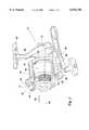
- FIG. 1shows a perspective view of a spinning type fishing reel and is exemplary of the environment of the present invention.
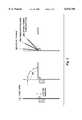
- FIG. 2depicts the elastic recovery characteristics of various compositions.
- FIG. 1a spinning-type fishing reel, according to the present invention, is shown at 10.
- the focus of the present inventionis on the rotor 12, and more specifically the bail wire 14, which is operable to wrap a supply of line around a spool 16 at the front of the reel 10.
- the reel 10 described hereinis only exemplary of the environment for the invention. Many variations in the configuration of the reel 10 shown are contemplated by the invention.
- the reel 10has a main housing 18 which encases an operating mechanism (not shown).
- the housing 18has an integrally formed stem 20 which terminates at a foot 22 which is attachable to a fishing rod (not shown) by conventional means.
- the rotor 12is rotated about a central longitudinal axis 24 by a crank handle 26 which is interrelated to the operating mechanism. As this occurs, the rotor 12 wraps the line continuously about the spool 16.
- the operating mechanismincludes structure for oscillating the spool 16 in a fore and aft direction, as indicated by the double-headed arrow 28, as the rotor 12 rotates, to thereby assure that the line is evenly distributed along the axial extent of the spool 16.
- the rotor 12has a skirt 30, a spool shoulder 32 and diametrically, oppositely located first and second ears 34, 36, which cooperatively define a support for a movable bail assembly 38.
- the bail assembly 38has a first bail arm 40 mounted to the first bail ear 34 and a second bail arm 42 mounted to the second bail ear 36.
- the ends of U-shaped bail wire 14are fixedly attached, one each to the bail arms 40, 42, so that the bail arms 40, 42 and bail wire 14 are movable as a unit.
- the first bail arm 40is connected to the first bail ear 34 to be pivotable relative thereto about an axis.
- the second bail arm 42is attached to the second bail ear 36 for pivoting movement relative thereto about a parallel axis.
- the bail assembly 38is pivotable as a unit relative to the rotor 12 about the axes between a cast position and a retrieve position.
- an over-center bias mechanism(not shown) within at least one of the bail ears 34, 36, the bail arms 40, 42, and thus the entire bail assembly 38, are biased into the cast and retrieve positions as the bail assembly 38 approaches each.
- Suitable structure for pivotably attaching the bail assembly 38 to the body 30 and for biasing the bail assembly 38 into the cast and retrieve positionsis well known in the art.
- one suitable structureis described in detail in U.S. Pat. No. 5,004,182, to Councilman, which is incorporated herein by reference.
- the lineIn the transition from the cast position to the retrieve position, the line is guided along an edge of the bail wire 14 and onto a line roller 44. With the reel 10 in the retrieve position, the line extends from the spool 16, around the cylindrical line roller 44, and forwardly from the line roller 44 away from the reel 10.
- crank handle 26With the bail assembly 38 in the retrieve position causes the rotor 12 to rotate clockwise about the axis 24 as viewed from the front of the spool 16. This brings the line against the line roller 44 and causes the line to wrap around the spool 16 as the rotor 12 rotates.
- Deflection as related to a bail wireis linearly related to the load divided by the product of the multiplicands E and I, where E is the modulus of elasticity (stiffness) of the bail wire material and I is the moment of inertia (related only to the shape of the bail wire's cross section).
- Eis the modulus of elasticity (stiffness) of the bail wire material
- Iis the moment of inertia (related only to the shape of the bail wire's cross section).
- Most bail designsutilize round stainless steel wire which has a moment of inertia (I) equal to 1/4 ⁇ r 4 .
- the diametersrange from 0.08 to 0.11 in. (2-2.8 mm) resulting in a calculated moment of inertia between 0.20 ⁇ 10 -5 in. 4 and 0.72 ⁇ 10 -5 in. 4 .
- Elasticity of stainless steel wireranges generally from 26 to 30 million psi.
- one bail design utilizing a plastic molded bailtransitions from a rectangular shape to an elliptical shape.
- the moment of inertia for this designvaries from approximately 1.4 ⁇ 10 -4 in. 4 to 1.0 ⁇ 10 -2 in. 4 in one direction and from 0.45 ⁇ 10 -2 in. 4 to 2.0 ⁇ 10 -2 in.
- the present inventionemploys in one aspect a bail wire preselected to possess a product of E ⁇ I at or below 45 lbs.-in. 2 and, most preferably, around 5 lbs.-in. 2 .
- Eis approximately 8 million psi and I is approximately 6.4 ⁇ 10 -7 in. 4 .
- the inventionencompasses a decreasing range from 45 lbs.-in. 2 downward whose criticality is manifest in improved flexibility in the bail wire so the bail wire can more easily avoid bearing the entire force of an accidental load and dampen load forces transmitted to the bail wire support structure while maintaining sufficient stiffness to accommodate the basic functions of a bail wire.
- the inventive bail wireis preselected to possess a heretofore unachievably low weight per unit length.
- the aforedescribed stainless steel bailshave a weight per unit length from approximately 1.3 ⁇ 10 -3 to 2.7 ⁇ 10 -3 lbs./in.
- the known plastic bails, having a density of approximately 0.04 lbs./in. 3 and a cross section varying from 0.03 to 0.09 in. 2possess a weight per unit of length ranging from approximately 1.2 ⁇ 10 -3 to 4.0 ⁇ 10 -3 lbs./in.
- the inventive bail provided hereinhas a weight per unit length equal to or less than 1.0 ⁇ 10 -3 lbs./in. and, most preferably, of about 0.7 ⁇ 10 -3 lbs./in.
- the criticality of this rangeis manifest in improved reel balance and performance.
- Both aspects of the inventionare achieved in a nickel-titanium alloy bail wire and, most preferably, a cylindrical nickel-titanium bail wire containing 55-56 weight percent nickel and 44-45 weight percent titanium (about 50 atomic percent each).
- the inventive bail wirehas an optimal diameter of about 0.06 in. and a density of about 0.25 lbs./in. 3 . Its modulus of elasticity is approximately 8 million psi, and it possesses a moment of inertia of about 6.4 ⁇ 10 -7 in. 4 . Consequently, in the most preferred inventive bail wire the value of E ⁇ I is 5.12 lbs.-in. 2 and its weight per unit length is 0.71 ⁇ 10 -3 lbs./in.
- Nitinolexhibits two unique properties depending upon its particular composition and the manner in which it is prepared, that is, “shape memory” and “superelasticity".
- shape memory effectdescribes the process of restoring the original shape of a plastically deformed sample by heating it to achieve a crystalline phase change known as “thermoelastic martensitic transformation”.
- transition (or transformation) temperaturenitinol has a soft "martensitic” microstructure which is deformable. Heating the material converts it to its high strength, austenitic condition. The transformation to and from the two states can be repeated by subjecting the material to heating and cooling cycles.
- the superelasticity effectis achieved when the alloy is stress induced in a temperature range above the transition temperature. This effect is caused by the stress-induced formation of some martensite above its normal temperature. Because it has been formed above its normal temperature, the martensite reverts, i.e., springs back, immediately to undeformed austenite as soon as the stress is removed.
- the preferred nitinol bail wireis locked in its austenite form through the temperature variants it will experience during use so that it may exhibit superelasticity.
- the inventive bail wireis constructed of austenitic nitinol having the preferred composition described above, a transition temperature (i.e., an austenitic finish temperature) of -25° C. ⁇ 5° C. and exhibiting superelasticity in a temperature range of -25° C. to 40° C.
- the shape of the inventive bail wireis set by constraining the nitinol element on a fixture of the desired shape and applying an appropriate heat treatment as is known in the art.
- FIG. 2demonstrates the flexibility of the preferred bail wire composition as compared to stainless steel wire, titanium spring wire and plastic.
- the nickel titanium wireexhibits an elastic recovery percentage of approximately 95% as compared to 50% for stainless steel, 70% for titanium spring wire and 0% for plastic.
Landscapes
- Life Sciences & Earth Sciences (AREA)
- Environmental Sciences (AREA)
- Animal Husbandry (AREA)
- Biodiversity & Conservation Biology (AREA)
- Ropes Or Cables (AREA)
- Storage Of Web-Like Or Filamentary Materials (AREA)
Abstract
Description
Claims (22)
Priority Applications (7)
| Application Number | Priority Date | Filing Date | Title |
|---|---|---|---|
| US09/311,945US6076756A (en) | 1999-05-14 | 1999-05-14 | Superelastic, lightweight bail wire for spinning fishing reels |
| EP00302068AEP1051905A1 (en) | 1999-05-14 | 2000-03-14 | Superelastic, lightweight bail wire for spinning type fishing reels |
| US09/527,756US6257513B1 (en) | 1999-05-14 | 2000-03-17 | Spinning reel with improved bail |
| KR1020000017528AKR100335248B1 (en) | 1999-05-14 | 2000-04-04 | Superelastic, lightweight bail wire for spinning type fishing reels |
| JP2000127395AJP2000342130A (en) | 1999-05-14 | 2000-04-27 | Fishing reel of spinning type |
| NO20002405ANO20002405L (en) | 1999-05-14 | 2000-05-09 | Super elastic, lightweight reel fastener |
| CN00108536ACN1273774A (en) | 1999-05-14 | 2000-05-12 | Super-electric, light weight additional fish wire of rotary reel |
Applications Claiming Priority (1)
| Application Number | Priority Date | Filing Date | Title |
|---|---|---|---|
| US09/311,945US6076756A (en) | 1999-05-14 | 1999-05-14 | Superelastic, lightweight bail wire for spinning fishing reels |
Related Child Applications (1)
| Application Number | Title | Priority Date | Filing Date |
|---|---|---|---|
| US09/527,756Continuation-In-PartUS6257513B1 (en) | 1999-05-14 | 2000-03-17 | Spinning reel with improved bail |
Publications (1)
| Publication Number | Publication Date |
|---|---|
| US6076756Atrue US6076756A (en) | 2000-06-20 |
Family
ID=23209175
Family Applications (2)
| Application Number | Title | Priority Date | Filing Date |
|---|---|---|---|
| US09/311,945Expired - LifetimeUS6076756A (en) | 1999-05-14 | 1999-05-14 | Superelastic, lightweight bail wire for spinning fishing reels |
| US09/527,756Expired - LifetimeUS6257513B1 (en) | 1999-05-14 | 2000-03-17 | Spinning reel with improved bail |
Family Applications After (1)
| Application Number | Title | Priority Date | Filing Date |
|---|---|---|---|
| US09/527,756Expired - LifetimeUS6257513B1 (en) | 1999-05-14 | 2000-03-17 | Spinning reel with improved bail |
Country Status (6)
| Country | Link |
|---|---|
| US (2) | US6076756A (en) |
| EP (1) | EP1051905A1 (en) |
| JP (1) | JP2000342130A (en) |
| KR (1) | KR100335248B1 (en) |
| CN (1) | CN1273774A (en) |
| NO (1) | NO20002405L (en) |
Cited By (3)
| Publication number | Priority date | Publication date | Assignee | Title |
|---|---|---|---|---|
| US6257513B1 (en) | 1999-05-14 | 2001-07-10 | Brunswick Corporation | Spinning reel with improved bail |
| US7222809B1 (en) | 2005-11-14 | 2007-05-29 | W.C. Bradley/Zebco Holdings, Inc. | Bail assembly for spinning reel |
| USD861827S1 (en) | 2017-07-11 | 2019-10-01 | W.C. Bradley/Zebco Holdings, Inc. | Spinning reel |
Families Citing this family (12)
| Publication number | Priority date | Publication date | Assignee | Title |
|---|---|---|---|---|
| US6602272B2 (en) | 2000-11-02 | 2003-08-05 | Advanced Cardiovascular Systems, Inc. | Devices configured from heat shaped, strain hardened nickel-titanium |
| US7976648B1 (en) | 2000-11-02 | 2011-07-12 | Abbott Cardiovascular Systems Inc. | Heat treatment for cold worked nitinol to impart a shape setting capability without eventually developing stress-induced martensite |
| US6626937B1 (en)* | 2000-11-14 | 2003-09-30 | Advanced Cardiovascular Systems, Inc. | Austenitic nitinol medical devices |
| US6855161B2 (en) | 2000-12-27 | 2005-02-15 | Advanced Cardiovascular Systems, Inc. | Radiopaque nitinol alloys for medical devices |
| US20020152668A1 (en)* | 2001-04-19 | 2002-10-24 | Lybarger Michael A. | Superelastic fishing rod |
| US7942892B2 (en) | 2003-05-01 | 2011-05-17 | Abbott Cardiovascular Systems Inc. | Radiopaque nitinol embolic protection frame |
| US7681821B2 (en)* | 2008-02-13 | 2010-03-23 | W.C. Bradley/Zebco Holdings, Inc. | Demonstration mode for electronic fishing reel |
| US8096493B2 (en)* | 2008-04-08 | 2012-01-17 | Bennis Gary L | Bail release mechanism for spinning reels |
| US7896277B2 (en)* | 2008-08-04 | 2011-03-01 | William Lombardo | Fishing reel |
| US7922112B2 (en)* | 2009-04-20 | 2011-04-12 | Zeebaas, Llc | Bail for spinning reel |
| US8708268B2 (en) | 2011-10-11 | 2014-04-29 | William Joseph Lombardo | Fishing reel |
| KR102367102B1 (en)* | 2021-08-03 | 2022-02-23 | 장정필 | Combine method of fishing rig and lead line |
Citations (6)
| Publication number | Priority date | Publication date | Assignee | Title |
|---|---|---|---|---|
| US4874144A (en)* | 1986-09-22 | 1989-10-17 | Ryobi, Ltd. | Bail for spinning reel |
| US4884761A (en)* | 1986-02-14 | 1989-12-05 | Rupert Kuntze | Line bail, as well as the associated fishing reel |
| US4895438A (en)* | 1983-12-06 | 1990-01-23 | Cvi/Beta Ventures, Inc. | Eyeglass frame including shape-memory elements |
| US5203103A (en)* | 1992-09-02 | 1993-04-20 | Hawley James M | Action fishing lure |
| US5547140A (en)* | 1992-05-13 | 1996-08-20 | Shimano, Inc. | Spinning reel having an anti-reverse mechanism |
| US5637089A (en)* | 1990-12-18 | 1997-06-10 | Advanced Cardiovascular Systems, Inc. | Superelastic guiding member |
Family Cites Families (9)
| Publication number | Priority date | Publication date | Assignee | Title |
|---|---|---|---|---|
| US4426045A (en) | 1979-10-18 | 1984-01-17 | Brunswick Corporation | Bail trip mechanism for fishing reel |
| US4676450B1 (en) | 1984-01-06 | 1991-06-25 | Quick bail opening system for fishing reel | |
| US5004182A (en) | 1988-06-15 | 1991-04-02 | Zebco Corporation | Convertible bail opening system |
| JPH03236732A (en)* | 1989-12-04 | 1991-10-22 | Nippon Seisen Co Ltd | Tip of fishing rod |
| DE4307593C1 (en)* | 1993-03-10 | 1994-08-04 | Fraunhofer Ges Forschung | Filament structure of shape memory alloy wires |
| US5713529A (en) | 1995-04-10 | 1998-02-03 | Zebco Div. Of Brunswick Corporation | Balanced rotor spinning fishing reel |
| WO1998024309A1 (en)* | 1996-12-06 | 1998-06-11 | Outdoor Innovations, L.L.C. | Spinner-type fishing lures and wire and cable fishing leaders |
| CA2345317A1 (en)* | 1998-09-24 | 2000-03-30 | Alan Gnann | Fishing rod guides, tops and hook keepers and method |
| US6076756A (en) | 1999-05-14 | 2000-06-20 | Brunswick Corporation | Superelastic, lightweight bail wire for spinning fishing reels |
- 1999
- 1999-05-14USUS09/311,945patent/US6076756A/ennot_activeExpired - Lifetime
- 2000
- 2000-03-14EPEP00302068Apatent/EP1051905A1/ennot_activeWithdrawn
- 2000-03-17USUS09/527,756patent/US6257513B1/ennot_activeExpired - Lifetime
- 2000-04-04KRKR1020000017528Apatent/KR100335248B1/ennot_activeExpired - Fee Related
- 2000-04-27JPJP2000127395Apatent/JP2000342130A/enactivePending
- 2000-05-09NONO20002405Apatent/NO20002405L/enunknown
- 2000-05-12CNCN00108536Apatent/CN1273774A/enactivePending
Patent Citations (7)
| Publication number | Priority date | Publication date | Assignee | Title |
|---|---|---|---|---|
| US4895438A (en)* | 1983-12-06 | 1990-01-23 | Cvi/Beta Ventures, Inc. | Eyeglass frame including shape-memory elements |
| US4884761A (en)* | 1986-02-14 | 1989-12-05 | Rupert Kuntze | Line bail, as well as the associated fishing reel |
| US4874144A (en)* | 1986-09-22 | 1989-10-17 | Ryobi, Ltd. | Bail for spinning reel |
| US5637089A (en)* | 1990-12-18 | 1997-06-10 | Advanced Cardiovascular Systems, Inc. | Superelastic guiding member |
| US5547140A (en)* | 1992-05-13 | 1996-08-20 | Shimano, Inc. | Spinning reel having an anti-reverse mechanism |
| US5586734A (en)* | 1992-05-13 | 1996-12-24 | Shimano Inc. | Spinning reel having an anti-reverse mechanism |
| US5203103A (en)* | 1992-09-02 | 1993-04-20 | Hawley James M | Action fishing lure |
Non-Patent Citations (20)
| Title |
|---|
| Hodgson, Darel E., Ming H. Wu and Robert J. Biermann. "Shape Memory Alloys." Printed from www.sma-inc.com on Apr. 13, 1999, pp. 1-12. |
| Hodgson, Darel E., Ming H. Wu and Robert J. Biermann. Shape Memory Alloys. Printed from www.sma inc.com on Apr. 13, 1999, pp. 1 12.* |
| Kauffman, George B. and Issac Mayo. "The Metal with a Memory: A combination of accident, luck, and hard work produced nitinol, an advanced `intelligent` metal." Invention & Technology. Fall 1993, pp. 18-23. |
| Kauffman, George B. and Issac Mayo. "The Story of Nitinol: The Serendipitous Discovery of the Memory Metal and Its Application." The Chemical Educator. 1996. vol. 2, No. 2, pp. 1-21. |
| Kauffman, George B. and Issac Mayo. The Metal with a Memory: A combination of accident, luck, and hard work produced nitinol, an advanced intelligent metal. Invention & Technology . Fall 1993, pp. 18 23.* |
| Kauffman, George B. and Issac Mayo. The Story of Nitinol: The Serendipitous Discovery of the Memory Metal and Its Application. The Chemical Educator . 1996. vol. 2, No. 2, pp. 1 21.* |
| NDC: Nitinol Devices and Components. Nitinol Applications. Printed from www.nitinol.com on Apr. 13, 1999, pp. 1 8.* |
| NDC: Nitinol Devices and Components. Nitinol Applications. Printed from www.nitinol.com on Apr. 13, 1999, pp. 1-8. |
| NDC: Nitinol Devices and Components. Nitinol Technology. Printed from www.nitinol.com on Apr. 13, 1999, pp. 1 3.* |
| NDC: Nitinol Devices and Components. Nitinol Technology. Printed from www.nitinol.com on Apr. 13, 1999, pp. 1-3. |
| NiTi Smart Sheet. No. 1. Glossary of NiTi Terminology. Printed from www.sma inc.com on Apr. 13, 1999, pp. 1 2.* |
| NiTi Smart Sheet. No. 1. Glossary of NiTi Terminology. Printed from www.sma-inc.com on Apr. 13, 1999, pp. 1-2. |
| NiTi Smart Sheet. No. 13. Specifying NiTi Materials. Printed from www.sma inc.com on Apr. 13, 1999, pp. 1 6.* |
| NiTi Smart Sheet. No. 13. Specifying NiTi Materials. Printed from www.sma-inc.com on Apr. 13, 1999, pp. 1-6. |
| NiTi Smart Sheet. No. 2. Introduction to Shape Memory and Superelasticity. Printed from www.sma inc.com on Apr. 13, 1999, pp. 1 2.* |
| NiTi Smart Sheet. No. 2. Introduction to Shape Memory and Superelasticity. Printed from www.sma-inc.com on Apr. 13, 1999, pp. 1-2. |
| NiTi Smart Sheet. No. 6. Setting Shapes in NiTi. Printed from www.sma inc.com on Apr. 13, 1999, pp. 1.* |
| NiTi Smart Sheet. No. 6. Setting Shapes in NiTi. Printed from www.sma-inc.com on Apr. 13, 1999, pp. 1. |
| Shape Memory Applications, Inc. NiTi Materials, Components, and Development Services. Printed from www.sma inc.com on Apr. 13, 1999, pp. 1 2.* |
| Shape Memory Applications, Inc. NiTi Materials, Components, and Development Services. Printed from www.sma-inc.com on Apr. 13, 1999, pp. 1-2. |
Cited By (3)
| Publication number | Priority date | Publication date | Assignee | Title |
|---|---|---|---|---|
| US6257513B1 (en) | 1999-05-14 | 2001-07-10 | Brunswick Corporation | Spinning reel with improved bail |
| US7222809B1 (en) | 2005-11-14 | 2007-05-29 | W.C. Bradley/Zebco Holdings, Inc. | Bail assembly for spinning reel |
| USD861827S1 (en) | 2017-07-11 | 2019-10-01 | W.C. Bradley/Zebco Holdings, Inc. | Spinning reel |
Also Published As
| Publication number | Publication date |
|---|---|
| NO20002405L (en) | 2000-11-15 |
| JP2000342130A (en) | 2000-12-12 |
| KR20010014685A (en) | 2001-02-26 |
| NO20002405D0 (en) | 2000-05-09 |
| KR100335248B1 (en) | 2002-05-06 |
| CN1273774A (en) | 2000-11-22 |
| EP1051905A1 (en) | 2000-11-15 |
| US6257513B1 (en) | 2001-07-10 |
Similar Documents
| Publication | Publication Date | Title |
|---|---|---|
| US6076756A (en) | Superelastic, lightweight bail wire for spinning fishing reels | |
| US7163168B2 (en) | Spinning reel handle assembly | |
| KR100695899B1 (en) | Spinning Reel Bale Inverter | |
| JPH10276629A (en) | Bail arm for spinning reel | |
| JP2007006710A (en) | Double bearing reel | |
| US20070033855A1 (en) | Flexible segment fishing pole | |
| GB2260250A (en) | Spinning reel having rotational balance mechanism for rotor. | |
| US4601437A (en) | Spinning reel | |
| KR20030055176A (en) | Spinning-reel bail-tripping device | |
| US6971599B2 (en) | Spinning reel rotor braking device | |
| JP3470855B2 (en) | Bale arm of spinning reel | |
| US20020152668A1 (en) | Superelastic fishing rod | |
| HK1034877A (en) | Superelastick, lightweight bail wire for spinning type fishing reels | |
| JP4324461B2 (en) | Spinning reel rotor braking device | |
| AU2020225376B2 (en) | Fishing rod | |
| JP2895897B2 (en) | Spinning reel | |
| JP2005176779A5 (en) | ||
| JP3555984B2 (en) | fishing rod | |
| JP2573322Y2 (en) | Spinning reel | |
| JP4711968B2 (en) | Movable mechanism | |
| JP3759576B2 (en) | Spinning reel bale reversing device | |
| JP2001136873A (en) | Spinning reel | |
| JP3753414B2 (en) | Spinning reel rotor braking device | |
| JP4307043B2 (en) | Superelastic power unit and power storage unit | |
| JP2003310113A (en) | Rotor-braking device of spinning reel |
Legal Events
| Date | Code | Title | Description |
|---|---|---|---|
| AS | Assignment | Owner name:BRUNSWICK CORPORATION, ILLINOIS Free format text:ASSIGNMENT OF ASSIGNORS INTEREST;ASSIGNOR:SPORTSWIRE L.L.C.;REEL/FRAME:010716/0127 Effective date:20000315 Owner name:SPORTSWIRE L.L.C., OKLAHOMA Free format text:ASSIGNMENT OF ASSIGNORS INTEREST;ASSIGNORS:BERENDT, CARL J.;JOHNSON, WILLIAM B.;REEL/FRAME:010716/0138 Effective date:20000315 Owner name:BRUNSWICK CORPORATION, ILLINOIS Free format text:ASSIGNMENT OF ASSIGNORS INTEREST;ASSIGNOR:COCKERHAM, RAYFORD A.;REEL/FRAME:010716/0161 Effective date:20000215 | |
| STCF | Information on status: patent grant | Free format text:PATENTED CASE | |
| AS | Assignment | Owner name:W.C. BRADLEY/ZEBCO HOLDINGS, INC. D/B/A ZEBCO, GEO Free format text:ASSIGNMENT OF ASSIGNORS INTEREST;ASSIGNORS:BRUNSWICK CORPORATION;ZEBCO CORPORATION;REEL/FRAME:012280/0501 Effective date:20010629 | |
| RR | Request for reexamination filed | Effective date:20020430 | |
| FEPP | Fee payment procedure | Free format text:PAYOR NUMBER ASSIGNED (ORIGINAL EVENT CODE: ASPN); ENTITY STATUS OF PATENT OWNER: LARGE ENTITY | |
| B1 | Reexamination certificate first reexamination | Free format text:THE PATENTABILITY OF CLAIMS 1-22 IS CONFIRMED. | |
| FPAY | Fee payment | Year of fee payment:4 | |
| FPAY | Fee payment | Year of fee payment:8 | |
| REMI | Maintenance fee reminder mailed | ||
| FPAY | Fee payment | Year of fee payment:12 |