US6075340A - Battery pack having memory - Google Patents
Battery pack having memoryDownload PDFInfo
- Publication number
- US6075340A US6075340AUS09/270,302US27030299AUS6075340AUS 6075340 AUS6075340 AUS 6075340AUS 27030299 AUS27030299 AUS 27030299AUS 6075340 AUS6075340 AUS 6075340A
- Authority
- US
- United States
- Prior art keywords
- battery pack
- battery
- utilization device
- portable
- circuitry
- Prior art date
- Legal status (The legal status is an assumption and is not a legal conclusion. Google has not performed a legal analysis and makes no representation as to the accuracy of the status listed.)
- Expired - Fee Related
Links
Images


Classifications
- H—ELECTRICITY
- H01—ELECTRIC ELEMENTS
- H01M—PROCESSES OR MEANS, e.g. BATTERIES, FOR THE DIRECT CONVERSION OF CHEMICAL ENERGY INTO ELECTRICAL ENERGY
- H01M6/00—Primary cells; Manufacture thereof
- H01M6/50—Methods or arrangements for servicing or maintenance, e.g. for maintaining operating temperature
- H01M6/5044—Cells or batteries structurally combined with cell condition indicating means
- H01M6/505—Cells combined with indicating means for external visualization of the condition, e.g. by change of colour or of light intensity
- G—PHYSICS
- G06—COMPUTING OR CALCULATING; COUNTING
- G06F—ELECTRIC DIGITAL DATA PROCESSING
- G06F1/00—Details not covered by groups G06F3/00 - G06F13/00 and G06F21/00
- G06F1/26—Power supply means, e.g. regulation thereof
- G06F1/263—Arrangements for using multiple switchable power supplies, e.g. battery and AC
- H—ELECTRICITY
- H01—ELECTRIC ELEMENTS
- H01M—PROCESSES OR MEANS, e.g. BATTERIES, FOR THE DIRECT CONVERSION OF CHEMICAL ENERGY INTO ELECTRICAL ENERGY
- H01M10/00—Secondary cells; Manufacture thereof
- H01M10/42—Methods or arrangements for servicing or maintenance of secondary cells or secondary half-cells
- H01M10/425—Structural combination with electronic components, e.g. electronic circuits integrated to the outside of the casing
- H01M10/4257—Smart batteries, e.g. electronic circuits inside the housing of the cells or batteries
- H—ELECTRICITY
- H01—ELECTRIC ELEMENTS
- H01M—PROCESSES OR MEANS, e.g. BATTERIES, FOR THE DIRECT CONVERSION OF CHEMICAL ENERGY INTO ELECTRICAL ENERGY
- H01M10/00—Secondary cells; Manufacture thereof
- H01M10/42—Methods or arrangements for servicing or maintenance of secondary cells or secondary half-cells
- H01M10/44—Methods for charging or discharging
- H—ELECTRICITY
- H01—ELECTRIC ELEMENTS
- H01M—PROCESSES OR MEANS, e.g. BATTERIES, FOR THE DIRECT CONVERSION OF CHEMICAL ENERGY INTO ELECTRICAL ENERGY
- H01M10/00—Secondary cells; Manufacture thereof
- H01M10/42—Methods or arrangements for servicing or maintenance of secondary cells or secondary half-cells
- H01M10/48—Accumulators combined with arrangements for measuring, testing or indicating the condition of cells, e.g. the level or density of the electrolyte
- H01M10/486—Accumulators combined with arrangements for measuring, testing or indicating the condition of cells, e.g. the level or density of the electrolyte for measuring temperature
- H—ELECTRICITY
- H01—ELECTRIC ELEMENTS
- H01M—PROCESSES OR MEANS, e.g. BATTERIES, FOR THE DIRECT CONVERSION OF CHEMICAL ENERGY INTO ELECTRICAL ENERGY
- H01M50/00—Constructional details or processes of manufacture of the non-active parts of electrochemical cells other than fuel cells, e.g. hybrid cells
- H01M50/20—Mountings; Secondary casings or frames; Racks, modules or packs; Suspension devices; Shock absorbers; Transport or carrying devices; Holders
- H01M50/204—Racks, modules or packs for multiple batteries or multiple cells
- H01M50/207—Racks, modules or packs for multiple batteries or multiple cells characterised by their shape
- H01M50/213—Racks, modules or packs for multiple batteries or multiple cells characterised by their shape adapted for cells having curved cross-section, e.g. round or elliptic
- H—ELECTRICITY
- H02—GENERATION; CONVERSION OR DISTRIBUTION OF ELECTRIC POWER
- H02J—CIRCUIT ARRANGEMENTS OR SYSTEMS FOR SUPPLYING OR DISTRIBUTING ELECTRIC POWER; SYSTEMS FOR STORING ELECTRIC ENERGY
- H02J7/00—Circuit arrangements for charging or depolarising batteries or for supplying loads from batteries
- H02J7/00032—Circuit arrangements for charging or depolarising batteries or for supplying loads from batteries characterised by data exchange
- H02J7/00036—Charger exchanging data with battery
- H—ELECTRICITY
- H02—GENERATION; CONVERSION OR DISTRIBUTION OF ELECTRIC POWER
- H02J—CIRCUIT ARRANGEMENTS OR SYSTEMS FOR SUPPLYING OR DISTRIBUTING ELECTRIC POWER; SYSTEMS FOR STORING ELECTRIC ENERGY
- H02J7/00—Circuit arrangements for charging or depolarising batteries or for supplying loads from batteries
- H02J7/00032—Circuit arrangements for charging or depolarising batteries or for supplying loads from batteries characterised by data exchange
- H02J7/00038—Circuit arrangements for charging or depolarising batteries or for supplying loads from batteries characterised by data exchange using passive battery identification means, e.g. resistors or capacitors
- H—ELECTRICITY
- H02—GENERATION; CONVERSION OR DISTRIBUTION OF ELECTRIC POWER
- H02J—CIRCUIT ARRANGEMENTS OR SYSTEMS FOR SUPPLYING OR DISTRIBUTING ELECTRIC POWER; SYSTEMS FOR STORING ELECTRIC ENERGY
- H02J7/00—Circuit arrangements for charging or depolarising batteries or for supplying loads from batteries
- H02J7/00047—Circuit arrangements for charging or depolarising batteries or for supplying loads from batteries with provisions for charging different types of batteries
- H—ELECTRICITY
- H02—GENERATION; CONVERSION OR DISTRIBUTION OF ELECTRIC POWER
- H02J—CIRCUIT ARRANGEMENTS OR SYSTEMS FOR SUPPLYING OR DISTRIBUTING ELECTRIC POWER; SYSTEMS FOR STORING ELECTRIC ENERGY
- H02J7/00—Circuit arrangements for charging or depolarising batteries or for supplying loads from batteries
- H02J7/0047—Circuit arrangements for charging or depolarising batteries or for supplying loads from batteries with monitoring or indicating devices or circuits
- H—ELECTRICITY
- H02—GENERATION; CONVERSION OR DISTRIBUTION OF ELECTRIC POWER
- H02J—CIRCUIT ARRANGEMENTS OR SYSTEMS FOR SUPPLYING OR DISTRIBUTING ELECTRIC POWER; SYSTEMS FOR STORING ELECTRIC ENERGY
- H02J7/00—Circuit arrangements for charging or depolarising batteries or for supplying loads from batteries
- H02J7/0068—Battery or charger load switching, e.g. concurrent charging and load supply
- H—ELECTRICITY
- H02—GENERATION; CONVERSION OR DISTRIBUTION OF ELECTRIC POWER
- H02J—CIRCUIT ARRANGEMENTS OR SYSTEMS FOR SUPPLYING OR DISTRIBUTING ELECTRIC POWER; SYSTEMS FOR STORING ELECTRIC ENERGY
- H02J7/00—Circuit arrangements for charging or depolarising batteries or for supplying loads from batteries
- H02J7/0069—Charging or discharging for charge maintenance, battery initiation or rejuvenation
- H—ELECTRICITY
- H02—GENERATION; CONVERSION OR DISTRIBUTION OF ELECTRIC POWER
- H02J—CIRCUIT ARRANGEMENTS OR SYSTEMS FOR SUPPLYING OR DISTRIBUTING ELECTRIC POWER; SYSTEMS FOR STORING ELECTRIC ENERGY
- H02J7/00—Circuit arrangements for charging or depolarising batteries or for supplying loads from batteries
- H02J7/007—Regulation of charging or discharging current or voltage
- H02J7/0071—Regulation of charging or discharging current or voltage with a programmable schedule
- H—ELECTRICITY
- H02—GENERATION; CONVERSION OR DISTRIBUTION OF ELECTRIC POWER
- H02J—CIRCUIT ARRANGEMENTS OR SYSTEMS FOR SUPPLYING OR DISTRIBUTING ELECTRIC POWER; SYSTEMS FOR STORING ELECTRIC ENERGY
- H02J7/00—Circuit arrangements for charging or depolarising batteries or for supplying loads from batteries
- H02J7/007—Regulation of charging or discharging current or voltage
- H02J7/00711—Regulation of charging or discharging current or voltage with introduction of pulses during the charging process
- H—ELECTRICITY
- H02—GENERATION; CONVERSION OR DISTRIBUTION OF ELECTRIC POWER
- H02J—CIRCUIT ARRANGEMENTS OR SYSTEMS FOR SUPPLYING OR DISTRIBUTING ELECTRIC POWER; SYSTEMS FOR STORING ELECTRIC ENERGY
- H02J7/00—Circuit arrangements for charging or depolarising batteries or for supplying loads from batteries
- H02J7/007—Regulation of charging or discharging current or voltage
- H02J7/00712—Regulation of charging or discharging current or voltage the cycle being controlled or terminated in response to electric parameters
- H02J7/00714—Regulation of charging or discharging current or voltage the cycle being controlled or terminated in response to electric parameters in response to battery charging or discharging current
- H—ELECTRICITY
- H02—GENERATION; CONVERSION OR DISTRIBUTION OF ELECTRIC POWER
- H02J—CIRCUIT ARRANGEMENTS OR SYSTEMS FOR SUPPLYING OR DISTRIBUTING ELECTRIC POWER; SYSTEMS FOR STORING ELECTRIC ENERGY
- H02J7/00—Circuit arrangements for charging or depolarising batteries or for supplying loads from batteries
- H02J7/007—Regulation of charging or discharging current or voltage
- H02J7/007188—Regulation of charging or discharging current or voltage the charge cycle being controlled or terminated in response to non-electric parameters
- H02J7/007192—Regulation of charging or discharging current or voltage the charge cycle being controlled or terminated in response to non-electric parameters in response to temperature
- H02J7/007194—Regulation of charging or discharging current or voltage the charge cycle being controlled or terminated in response to non-electric parameters in response to temperature of the battery
- H—ELECTRICITY
- H02—GENERATION; CONVERSION OR DISTRIBUTION OF ELECTRIC POWER
- H02J—CIRCUIT ARRANGEMENTS OR SYSTEMS FOR SUPPLYING OR DISTRIBUTING ELECTRIC POWER; SYSTEMS FOR STORING ELECTRIC ENERGY
- H02J9/00—Circuit arrangements for emergency or stand-by power supply, e.g. for emergency lighting
- H02J9/04—Circuit arrangements for emergency or stand-by power supply, e.g. for emergency lighting in which the distribution system is disconnected from the normal source and connected to a standby source
- H02J9/06—Circuit arrangements for emergency or stand-by power supply, e.g. for emergency lighting in which the distribution system is disconnected from the normal source and connected to a standby source with automatic change-over, e.g. UPS systems
- H02J9/061—Circuit arrangements for emergency or stand-by power supply, e.g. for emergency lighting in which the distribution system is disconnected from the normal source and connected to a standby source with automatic change-over, e.g. UPS systems for DC powered loads
- G—PHYSICS
- G01—MEASURING; TESTING
- G01R—MEASURING ELECTRIC VARIABLES; MEASURING MAGNETIC VARIABLES
- G01R31/00—Arrangements for testing electric properties; Arrangements for locating electric faults; Arrangements for electrical testing characterised by what is being tested not provided for elsewhere
- G01R31/36—Arrangements for testing, measuring or monitoring the electrical condition of accumulators or electric batteries, e.g. capacity or state of charge [SoC]
- G01R31/3644—Constructional arrangements
- G01R31/3648—Constructional arrangements comprising digital calculation means, e.g. for performing an algorithm
- G—PHYSICS
- G01—MEASURING; TESTING
- G01R—MEASURING ELECTRIC VARIABLES; MEASURING MAGNETIC VARIABLES
- G01R31/00—Arrangements for testing electric properties; Arrangements for locating electric faults; Arrangements for electrical testing characterised by what is being tested not provided for elsewhere
- G01R31/36—Arrangements for testing, measuring or monitoring the electrical condition of accumulators or electric batteries, e.g. capacity or state of charge [SoC]
- G01R31/374—Arrangements for testing, measuring or monitoring the electrical condition of accumulators or electric batteries, e.g. capacity or state of charge [SoC] with means for correcting the measurement for temperature or ageing
- G—PHYSICS
- G01—MEASURING; TESTING
- G01R—MEASURING ELECTRIC VARIABLES; MEASURING MAGNETIC VARIABLES
- G01R31/00—Arrangements for testing electric properties; Arrangements for locating electric faults; Arrangements for electrical testing characterised by what is being tested not provided for elsewhere
- G01R31/36—Arrangements for testing, measuring or monitoring the electrical condition of accumulators or electric batteries, e.g. capacity or state of charge [SoC]
- G01R31/382—Arrangements for monitoring battery or accumulator variables, e.g. SoC
- G01R31/3842—Arrangements for monitoring battery or accumulator variables, e.g. SoC combining voltage and current measurements
- H—ELECTRICITY
- H01—ELECTRIC ELEMENTS
- H01M—PROCESSES OR MEANS, e.g. BATTERIES, FOR THE DIRECT CONVERSION OF CHEMICAL ENERGY INTO ELECTRICAL ENERGY
- H01M50/00—Constructional details or processes of manufacture of the non-active parts of electrochemical cells other than fuel cells, e.g. hybrid cells
- H01M50/50—Current conducting connections for cells or batteries
- H—ELECTRICITY
- H01—ELECTRIC ELEMENTS
- H01M—PROCESSES OR MEANS, e.g. BATTERIES, FOR THE DIRECT CONVERSION OF CHEMICAL ENERGY INTO ELECTRICAL ENERGY
- H01M6/00—Primary cells; Manufacture thereof
- H01M6/50—Methods or arrangements for servicing or maintenance, e.g. for maintaining operating temperature
- H01M6/5044—Cells or batteries structurally combined with cell condition indicating means
- Y—GENERAL TAGGING OF NEW TECHNOLOGICAL DEVELOPMENTS; GENERAL TAGGING OF CROSS-SECTIONAL TECHNOLOGIES SPANNING OVER SEVERAL SECTIONS OF THE IPC; TECHNICAL SUBJECTS COVERED BY FORMER USPC CROSS-REFERENCE ART COLLECTIONS [XRACs] AND DIGESTS
- Y02—TECHNOLOGIES OR APPLICATIONS FOR MITIGATION OR ADAPTATION AGAINST CLIMATE CHANGE
- Y02E—REDUCTION OF GREENHOUSE GAS [GHG] EMISSIONS, RELATED TO ENERGY GENERATION, TRANSMISSION OR DISTRIBUTION
- Y02E60/00—Enabling technologies; Technologies with a potential or indirect contribution to GHG emissions mitigation
- Y02E60/10—Energy storage using batteries
Definitions
- the present inventionmay be utilized as or in conjunction with the battery pack including electronic power saver as described in PCT publication PCT/US90/06383 published May 16, 1991. Said publication PCT/US90/06383 is incorporated herein by reference in its entirety.
- the present inventionmay be utilized as the rechargeable battery of a portable system as described in U.S. Pat. No. 5,363,031 issued Nov. 8, 1994. Said U.S. Pat. No. 5,363,031 is incorporated herein by reference in its entirety.
- the present inventionmay be utilized as the rechargeable battery of a portable system as described in U.S. application Ser. No. 07/837,650 (Attorney Docket No. 6599XZ) filed Feb. 18, 1992. Said application Ser. No. 07/837,650 is incorporated herein by reference in its entirety.
- the present inventionmay be protected from electrostatic discharge by utilizing the apparatus and method for electrostatic discharge protection as described in U.S. application Ser. No. 08/353,778 filed Dec. 12, 1994. Said application Ser. No. 08/353,778 is incorporated herein by reference in its entirety.
- the present inventionrelates to a battery conditioning system for battery means of portable computerized devices, and particularly to a hand-held device including data storage means for storing data pertinent to the battery means of the device, and to a battery conditioning control system including an external charging circuit equipped for communication with data storage means of the hand-held device and/or of the battery means operatively associated with such device.
- the control systemis capable of optimizing the performance of a rechargeable electrochemical storage medium while at the same time maximizing its useful life.
- the inventionalso relates to control systems generally, and to control systems forming part of hand-held units.
- Portable computerized systemsare presently being extensively utilized in a wide range of applications. For example, such systems may be utilized in delivery vehicles which are to be away from a central warehouse or the like for a major part of each working day. Recharging operations may take place in locations subject to extremes of temperature. It is particularly crucial to avoid an equipment failure where a portable device is a vital link to the completion of scheduled tasks at remote locations and the like. In such circumstances, a loss of adequate battery power can be just as detrimental as any other malfunction.
- the battery conditioning control systemis to be incorporated in hand-held devices, such control system should be lightweight and compact, and should consume minimum power.
- a microprocessor of a standard design and of minimum complexityis highly desirable.
- a particularly advantageous battery conditioning systemis achieved where significant portions of the conditioning circuitry are external to the battery operated portable device, and where the portable device contains data storage means which is capable of reliably and flexibly providing information, e.g., to the external circuitry for optimizing battery conditioning operations.
- Data storage meansmay be implemented within a battery pack in order to preserve battery characteristics of that particular battery so that unique battery data may be associated with the battery pack.
- the saved battery pack datamay be accessed by a portable battery powered device in which the battery pack is utilized so that charging and discharging routines may be optimized for the particular battery pack.
- a further object of the present inventionis to provide a control system particularly adapted to control battery conditioning of a variety of rechargeable battery means, automatically adaptable to hand-held devices having battery means of different types such as to require different conditioning parameters.
- Another object of the inventionis to provide a charging current control system for battery powered portable devices which is not only lightweight and compact but which consumes minimum power, and which preferably is adapted to be implemented as an integrated circuit of an economical and simple construction.
- An exemplary feature of the inventionresides in the provision of a battery conditioning system receptive of different hand-held devices and capable of communication therewith, e.g., to determine the type of conditioning required for respective different internal battery means thereof.
- a further feature of the inventionrelates to a battery conditioning system wherein the system can obtain a relatively accurate indication of the battery energy remaining available for use for one type or a plurality of different types of batteries, and supply the results to a memory means accompanying the battery means during portable operation.
- battery parametersincluding battery temperature can be monitored and transmitted to a conditioning system during a charging cycle, and the battery charging current can be adjusted accordingly.
- a count of such shallow charge cyclesmay be automatically maintained throughout the operating life of the battery system, such that deep discharge cycles may be effected as necessary to maintain desired performance standards.
- automatically operating battery monitoring and/or conditioning circuitrymay be secured with the battery pack for handling as a unit therewith.
- the monitoring circuitrymay receive its operating power from the battery pack during storage or handling such that a total history of the battery pack may be retained for example in a volatile memory circuit where such type of memory otherwise provides optimum characteristics for a portable system.
- the conditioning circuitrymay have means for effecting a deep discharge cycle, and concomitantly with the deep discharge cycle, a measure of actual battery capacity may be obtained. From such measured battery capacity and a continuous measurement of battery current during portable operation, a relatively accurate "fuel gauge" function becomes feasible such that the risk of battery failure during field operation can be essentially eliminated. The performance of a given type of battery in actual use can be accurately judged since the battery system can itself maintain a count of accumulated hours of use, and other relevant parameters.
- the conditioning systemis incorporated in the portable utilization device such that the programmed processor of the utilization device may itself automatically effect a deep discharge conditioning cycle and/or a deep discharge capacity test.
- the deep discharge cyclemay be effected at a controlled rate, such that the time for discharge from a fully charged condition to a selected discharge condition may itself represent a measure of battery capacity.
- the programmed processormay maintain a measure of operating time and/or elapsed time during portable operation, so as to provide an indication of remaining battery capacity.
- a time measure of operating timemay be utilized to automatically determine the time duration of the next charging cycle. When both a main battery and a back-up battery are present, the operating time of each may be individually accumulated, and used to control the time duration of the respective recharging operations.
- Additional features of a commercial system in successful useinclude individual charging and discharging circuits for a main battery and a back-up battery for reliable conditioning of the back-up battery independently of the state of the main battery. Desired parameters such as main battery voltage, ambient temperature (e.g., in the main battery case or in the battery compartment), and charging voltage may be obtained by means of an integrated circuit analog to digital converter, which thus replaces several comparators and many precision costly components of a prior implementation.
- battery charging currentwas set using a digital to analog converter to establish a set point for an analog current control loop
- a digital computerfor both computing a desired current set point and for modulating current pulses in the battery charging circuit for maintaining a desired average current.
- a computer circuit with a moderate clock ratemay determine current pulse modulation steps and control sampling of actual current pulses for purposes of generating a feedback signal.
- An aliasing type of sampling systematically taken at different phases of the actual current pulse waveformenables use of a particularly low sampling rate.
- a computer operating means of the portable deviceis programmed and provided with battery information sufficient to select an optimum battery charging rate, for example, e.g., a fast charge or a maintenance charge, and preferably to adjust the charge rate, e.g., based on a measure of battery temperature.
- an external standardized charging circuithas a default condition wherein a charging current is supplied suitable to older types of terminals. Such a charging circuit, however, can be controlled by the computer operating means of preferred types of portable devices so as to override the default charging rate.
- charging ratemay be a function not only of a respective rated battery capacity, but also of other parameters such as battery terminal voltage prior to coupling of the portable device with the charging circuit and/or extent of use of the portable device after a previous charge.
- battery terminal voltageprior to coupling of the portable device with the charging circuit and/or extent of use of the portable device after a previous charge.
- R. F. terminalsit is advantageous to avoid a resistance in series with the battery for measuring battery drain during use; an alternate approach measuring operating time in various modes can then be particularly attractive.
- An advantageous data communication coupling between a portable device computer operating means and a charging circuitis via a data storage register and digital to analog converter.
- the registercan be operated from a battery means while the computer operating means may be in a sleep mode, for example, once the register has received a suitable computer generated command.
- the digital to analog converterneed only be active during a battery charging cycle and can be decoupled from the battery means during portable operation.
- Such a digital to analog converteris particularly suitable for generating an analog control signal for overriding a default setting of a standardized charging circuit such as described herein above.
- a new RF terminal unitit is conceived that it may be advantageous to make the output of a battery temperature measuring transducer available at an external contact of the terminal so that a low cost charger could supply a charging current taking account of a relatively accurate measure of battery temperature. Further by making temperature transducer (nonzero) output dependent on the presence of charging potential at the terminal, the same temperature sensing line provides an indication as to whether charging potential is present.
- a battery pack having memorymay be implemented within the battery pack itself.
- the duty history of the battery along with present battery datamay be stored to be later retrieved by a utilization device.
- the utilization devicemay determine present battery conditions in order to relay such information to the operator and may apply appropriate charging algorithms taking into account present battery conditions along with past characteristic charge/discharge behavior in order to optimize future battery charging and discharging.
- the characteristic behavior exhibited by the battery packmay be stored in an electronic memory system along with other battery pack identifying or tagging information.
- the battery pack having memorymay be assembled using standard battery pack assembly techniques in order to maintain reliability and minimize the costs of the battery pack having memory.
- FIG. 1is a somewhat diagrammatic perspective view of a portable battery powered device which may incorporate a battery system in accordance with the teachings and principles of the present invention
- FIG. 2is a somewhat diagrammatic enlarged longitudinal sectional view showing the battery compartment section and adjacent portions of the portable device of FIG. 1, with a battery pack assembly disposed in the battery compartment in operative coupling relationship with a central processing unit of the portable device for purposes of power supply to the central processing unit and for purposes of transmission of data and command signals;
- FIG. 3is a somewhat diagrammatic perspective view of a battery system in accordance with the teaching and principles of the present invention.
- FIG. 4is a perspective view similar to FIG. 3 but illustrating the battery system enclosed in a protective casing, to form a complete battery pack assembly for insertion into the battery compartment of the portable device, as a unit;
- FIG. 5shows a block diagram for explaining the cooperative relationship of the electronic parts of the particular portable computer terminal device and battery system shown in FIGS. 1 through 4, by way of example and not by way of limitation;
- FIG. 6shows a typical plot of permissible continuous overcharge rate as a function of temperature, for a particular type of rechargeable electrochemical energy storage cell, by way of example and not by way of limitation;
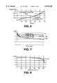
- FIG. 7is a plot of the effect of repetitive shallow cycling for the particular energy storage medium also represented by the plot of FIG. 6;
- FIG. 8is a plot of discharge characteristics for the particular energy storage medium also represented by the plots of FIGS. 6 and 7;
- FIGS. 9A and 9Bshow a specific circuit implementation in accordance with the block diagram of FIG. 5, by way of example and not by way of limitation;
- FIG. 10is a flow diagram for illustrating an exemplary control program for carrying out analog to digital conversion of battery parameter values utilizing the particular exemplary circuit of FIGS. 9A and 9B;
- FIG. 11is a flow diagram illustrating the general battery processor control program utilized in conjunction with simplified system currently in use
- FIG. 12is a block diagram of a simplified portable battery powered device in accordance with the present invention associated with a battery charger means, and also serves to illustrate a stationary battery conditioning system for spare battery packs;
- FIG. 13shows a specific implementation of the battery charge and deep discharge controller and monitor circuitry which is represented as a labeled rectangle in FIG. 12;
- FIG. 14is a flow diagram indicating the operating means for effecting an automatic discharge cycle with the specific circuitry of FIG. 13;
- FIG. 15shows a block diagram for illustrating an exemplary commercial implementation of the present invention
- FIG. 16Ashows a portion of an electric circuit diagram for illustrating preferred implementations of a direct current to direct current converter, a main battery charging circuit, a backup battery charging circuit, and main and backup discharge circuits for such commercial implementation;
- FIG. 16Bshows a continuation of the electric circuit diagram of FIG. 16A to the right, and particularly illustrates preferred regulator circuitry, preferred low power detection circuitry, and the preferred association of an integrated circuit analog to digital converter means with a main battery means and a backup battery means, in accordance with a preferred commercial implementation of the present invention
- FIG. 17is a flow diagram for illustrating the manner in which the power control circuitry of FIGS. 16A and 16B interacts with components 15-19 and 15-25 for FIG. 15 during operation of a preferred portable unit under battery power.
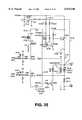
- FIG. 18is an electric circuit diagram for illustrating a preferred embodiment of battery charging current control system in accordance with the present invention.
- FIG. 19shows an exemplary current pulse waveform which may correspond with a maximum battery charging rate in a substantially linear operating range for an exemplary control system in accordance with FIG. 18;
- FIG. 20Ashows selected control pulses which may be generated during control of battery charging current in the control system of FIG. 18, and
- FIG. 20Bshows respective corresponding battery charging current pulses on the same time scale with vertically aligned portions of the waveforms of FIGS. 20A and 20B occurring at the same time;
- FIG. 21is a diagrammatic view of use in explaining the aliased sampling of actual current pulses in the battery charging circuit, and illustrating the case where thirty-two samples form a complete sampling cycle;
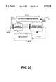
- FIG. 22is a block diagram for illustrating exemplary sampling circuitry for association with the V sense input of the processor means of FIG. 18;
- FIG. 23illustrates a battery conditioning system as described at col. 17, lines 51-68 of the incorporated U.S. Pat. No. 4,455,523 and wherein two-way communication may be established between memory means associated with a portable unit comprised of rechargeable battery means, and a non-portable central computer controlled conditioning station;
- FIG. 24shows a battery conditioning system wherein a battery identifying circuit element directly controls the set point of a battery charging circuit to determine a battery charging parameter, e.g., battery charging current;
- FIG. 25shows a highly integrated semiconductor device, e.g., for implementing the system of FIGS. 18-22;
- FIG. 26is an electric circuit block diagram showing a battery conditioning system wherein a preferred hand-held terminal unit contains battery parameter sensing means and computer operating means for optimizing battery charging current as supplied by an external circuit (which may correspond with a standardized circuit such a shown in FIG. 24 applicable to a complete family of hand-held terminals); and
- FIG. 27shows a new RF terminal unit including charge control and temperature transducer outputs as in FIG. 26, and also incorporating an interface for coupling with a local area network so as to enable batch transmission of data to and from the RF terminal.
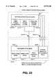
- FIG. 28depicts the electrical circuit arrangement of an exemplary battery pack having memory
- FIG. 29shows a physical arrangement of the components of the battery pack having memory in an exemplary manufacture of the invention.
- FIGS. 1 through 17The detailed description of FIGS. 1 through 17 is incorporated herein by reference to the specification at col. 4, line 25, through col. 66, line 4, of the incorporated U.S. Pat. No. 4,709,202.
- FIG. 18shows processor means such as an integrated circuit microprocessor 18-10 which may form part of a circuit package of a battery pack 18-12.
- the circuit packagemay be secured with a rechargeable battery means 18-20, an association of such parts being shown in detail in FIGS. 2, 3 and 4.
- a battery charging meanssuch as 12-24, FIG. 12, may provide a charging potential to a hand-held computer unit such as 71, FIG. 5, and the unit 71 may supply an operating voltage +V to microprocessor 18-10 and may supply a charging potential +CHG to a series circuit including a current switch or current regulator means 18-22, an energy storage inductor means 18-24, battery means 18-20, and a current sense resistor 18-26.
- the processor means 18-10may supply to line 18-27 rectangular pulses of a voltage waveform Vsw as shown in FIG. 20A.
- the duration or active duty cycle of the voltage pulses of waveform Vswis modulated in discrete modulation steps to vary the turn-on time of switch means 18-22, and thus to vary battery charging current.
- battery means 18-20may have battery charging parameter sensing means associated therewith as indicated at 18-28.
- Such parameter sensing meansmay have a battery temperature sensing transducer 18-30 corresponding to transducer 134, FIG. 9-A, and transducer 18-30 may be physically disposed in heat transfer relation to battery pack 18-12 as indicated in FIG. 18.
- processor means 18-10may be controlled by a constant frequency means such as crystal 18-32.
- the clock rate of crystal 18-32may be used to synchronize turn on of switch means 18-22 so that active duty cycles are initiated at a uniform time interval of less than one microsecond and may provide a desired number of modulation steps for the active duty cycle of the turn-on waveform Vsw.
- the operating frequency of crystal 18-32may be six megahertz (i.e., thirty-two times a duty cycle frequency of 187.5 kilohertz) and may provide a time interval between activations of switch means 18-22 of 5.3333 microseconds with each such time interval being subdivided into thirty-two modulation steps.
- a moderate operating frequency of crystal 18-32is favorable for a control system with low energy consumption, and an economical processor means.
- the turn-on time of switch means 18-22may have different possible time durations per cycle corresponding to respective different numbers of the thirty-two modulation steps.
- the modulation stepsmay represent increments of 166.7 nanoseconds in the time duration of the active duty cycle of the waveform Vsw at line 18-27.
- maximum current flow in inductor 18-24may correspond with a turn-on time corresponding to at least sixty percent of the maximum available on-time of switch means 18-22.
- current flowmay increase relatively linearly as represented in FIG. 19 by sloping line 19-1 for numbers of time increments between zero and twenty or more.
- the circuit 18includes means such as diode 18-36 for maintaining current flow when switch means 18-22 is turned off, the circuit preferably providing a current decay characteristic generally as indicated at 19-2 in FIG. 19.
- the currentmay decay to zero in less than one-half of the turn-on time of switch means 18-22, for the case of active duty cycles which provide a linear characteristic such as 19-1.
- the peak value 19-3 in FIG. 19corresponds to twenty time increments or 3.33 microseconds (20 times 166.7 nanoseconds equals 3.33 microseconds)
- the decay intervalmay be less than ten increments, i.e. less than 1.67 microseconds.
- FIG. 20Bshows the corresponding current flow in inductance 18-24, designated I(L) and the corresponding battery charging current I(CHG).
- the rising current characteristics 20-1 to 20-4are linear where the number of increments is less than the number corresponding to peak 19-3 in FIG. 19.
- current sense resistance 18-26is of a value much less than the resistance of battery means 18-20; for example, resistance means 18-26 may have a resistance value of 0.1 ohm.
- FIG. 20Bthus also represents the waveform Vsense supplied at line 18-38 of FIG. 18, for the respective durations of Vsw of FIG. 20A.
- the processor means 18-10includes analog to digital converter channels such as that associated with resistor 135, FIG. 9A, so that the battery temperature analog signal at 18-40 and the battery current analog signal at 18-38 may be converted into corresponding digital values.
- waveforms such as those represented in FIG. 20Bwould normally be sampled at a relatively high rate in comparison with the operating frequency of component 18-32
- the sampling rate of the pulsating analog waveform at line 18-38is made lower than the rate of component 18-32 and preferably less than the active duty cycle frequency of waveform Vsw.
- the analog to digital converter means of processor 18-10preferably deliberately under samples the current sense line 18-38 to alias the charging current waveform I(CHG) to a very low frequency.
- samplingmay take place roughly at a frame sampling rate of 1/64 Fsw or roughly 2929 hertz.
- the actual aliasing sampling rateis not precisely synchronized with the switch activation rate Fsw, but differs slightly therefrom, for example, by one time increment or duty cycle modulation step of waveform Vsw, e.g., by a time increment of 166.7 nanoseconds per frame interval.
- one complete scan of the pulse configuration of the Vsense waveform at line 18-38would take place for each 2049 Vsw pulses.
- the resultant sampled waveform for a complete sampling cycleis diagrammatically indicated in FIG. 21 for the example of sampling as represented in FIGS. 20A and 20B.
- the frame sampling rate for the Vsense waveform on line 18-38is roughly 1/256 Fsw, or about 732.42 hertz, then with one time increment of 167 nanoseconds added for each sampling frame, an actual sampling frequency of about 732.33 hertz results corresponding to 1.3655 milliseconds per sample. If thirty-two sample points of the Vsense waveform are scanned per complete sampling cycle, then one complete sampling cycle corresponds to 0.043696 second, or a frequency of 22.88 hertz.
- a corresponding average current valuecan be computed, by adding the most recent sample value (e.g. at ns33, FIG. 21) and subtracting the oldest sample value (e.g. sample ns1, FIG. 21), so that a new average current would be calculated at each 1.3655 milliseconds for the case of a sampling frequency of about 732.33 hertz.
- a sample and hold circuitmay retain the sampled value of Vsense during the analog to digital conversion process.
- the preferred embodiment with an aliased sampling rateis considered applicable to current measurements where changes in the current waveform pulses are relatively slow, e.g., slower than the rate of change shown in FIG. 20B, where the alternating polarity component of the Vsense voltage averages out over a complete sampling cycle, and where the need for dynamic regulation of the current I(L) is minimal, i.e. the average direct current level per complete sampling cycle is the critical value to be regulated.
- the slow rate aliasing type of samplingis useful to adapt the sampling frequency to that feasible with an economical and simple processing means 18-10 (e.g., a type 8048 microprocessor).
- Other schemes to scan the Vsense signalcould both skip frames and slip sample points, e.g.
- processor 18-10may read battery temperature via input 18-40 at ten second intervals, and adjust the charging current set point value accordingly at each ten second reading of temperature.
- a noise filter in the form of a digital algorithmmay insure that the actual digital current readings based on Vsense are free of disruptive noise.
- the active duty cycles of Vswmay be set to zero; for temperatures between minus twenty degrees Celsius and minus ten degrees Celsius (+14° F.), the charging current may be set to about C/20 (resulting in an average of about eight modulation increments for each active duty cycle of Vsw); for temperatures between minus ten degrees Celsius and zero degrees Celsius (32° F.), the charging current may be set to about C/16 (resulting in an average of about ten modulation increments for each active duty cycle of Vsw); for temperatures between zero degrees Celsius and ten degrees Celsius (50° F.), the charging current may be set to about C/10 (to produce an average of about sixteen modulation increments for each active duty cycle of Fsw); for temperatures between ten degrees Celsius and seventy degrees Celsius (158° F.), the charging rate may be set to about C/8;
- the programming of processor 18-10may simply provide a table of numbers of modulation increments for the active duty cycle of Fsw according to respective ranges of measured temperature readings in digital form and the values of measured charging current may not enter into the selection of modulation increments.
- the sampling of charging currentmay be used for the fuel gauge function during normal operation of the hand held unit such as indicated at 10 in FIGS. 1 and 2, or in FIGS. 10, or at 12-10, FIG. 12.
- the circuitry of FIG. 18may be permanently associated with the hand held device 10, rather than being a permanent part of the battery pack.
- the circuitry of FIG. 18may be a permanent part of the battery pack along with a casing 60, FIG.
- the rechargeable battery means 18-20, FIG. 18,may be readily removable from casing 60 so as to be replaceable without replacement of components such as 18-10, 18-22, 18-24, 18-26, 18-28, 18-30, and 18-32.
- the transducer 18-30need not be in physical proximity with the battery means 18-20.
- the processor 18-10 and switch means 18-22can be part of the same silicon chip, for example.
- sensing means 18-28may also receive an analog measure of battery voltage as indicated by a V(BATT) input at 18-42 and/or an analog measure of input charging voltage V(+CHG) as indicated at 18-44, and supply such analog measures to an analog to digital channel of processor means 18-10.
- the processor 18-10may load a number equal to the number of desired modulation increments for the active duty cycle of Vsw into a register, and apply a suitable turn on voltage to line 18-27 until a number of clock pulses of oscillator means 18-32 has been counted corresponding to the number selected.
- the voltage across current measuring resistor 18-26, FIG. 18,may be supplied via line 18-38 to a low offset voltage linear amplifier 22-10.
- the output signal at 22-12 from amplifier 22-10 and the analog signals of multiconductor line 18-40are supplied to respective sample and hold circuits of component 22-14.
- Successive samples of the battery current measurement waveformsuch as indicated at ns1, ns2, ns3, ns4, . . . , ns32, ns33, . . . , FIG. 21, may be selected by means of microprocessor 22-16 which is controlled by clock 18-32.
- Each samplemay be obtained over a sample interval which may be equal to the clock period interval of one-sixth microsecond, for example, and may be held until it is converted to digital form by component 22-18 and supplied to a register of microprocessor 22-16 e.g. via conductors of a data bus forming part of the interconnecting means 22-19.
- the other analog signalsare similarly sampled and transmitted e.g. to respective further registers of microprocessor 22-16.
- the microprocessor 22-16may be programmed to compute a new average battery charge rate with each sample of actual battery current after the first N samples.
- the microprocessorwould also take account of any changes in battery temperature, for example. As a specific example, it may be desired to maintain a maximum battery charging rate consistent with assurance of prolonged battery life, e.g., avoiding an excessive overcharge rate as discussed in relation to FIG. 6.
- processor means 18-10may include a stored look up table wherein for respective temperature ranges, respective different settings for the desired average battery charging current are entered.
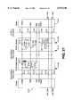
- An exemplary table based on FIG. 6is as follows:
- n10
- switch means 18-22would be turned on, and clock pulses of clock oscillator 18-32 would be counted until the number corresponding to the n value stored in the duty cycle register was reached. Switch means 18-22 would then be turned off.
- samplingwould take place as shown in FIG. 21. After sample ns32, a value of actual charging current would be calculated. If for example, the average actual current were calculated at 0.10° C., and the battery temperature remained in the same range of 76° F. to 98° F., there would be a zero error and the value of ten would remain in the duty cycle register.
- the microprocessor 22-16may be programmed to sample battery current during deep discharge of the battery means and during portable operation to obtain a measure of remaining battery life which may be displayed by the portable unit. See for example, Tables A and B herein.
- FIGS. 18, 19, 20A, 20B, 21 and 22include the following by way of example and not of limitation:
- Constant frequency duty cycle repetition rate for Vswe.g., a fraction of the clock rate of component 18-32 corresponding to a desired number of modulation increments per cycle of Vsw.
- Vsense at 18-38is measured via a low offset voltage linear amplifier, a sample and hold circuit, and an analog to digital converter, e.g., as indicated in FIG. 22.
- Processor 18-10obtains a measure of battery current during both battery charging and battery discharging operations.
- Processor 18-10selects the duty cycle of Vsw according to ambient temperature to prolong battery life and enhance reliability of the complete hand-held unit.
- the illustrated embodimentexemplifies a method of operation in a battery charging system wherein current is intermittently supplied from a voltage source means, e.g., V(+CHG), FIG. 18, to a chargeable battery means 18-20 via an energy storage means, e.g., inductance 18-24.
- the circuit arrangementis such that battery charging current continues to flow from the energy storage means to the battery means, e.g., via diode 18-36, at each interruption of the current flow at current regulator means 18-22.
- the intermittent actuation of current regulating means 18-22produces a fluctuating battery charging current such as represented in FIGS. 19 and 20B which fluctuates in each of the successive operating cycles.
- the sampling means of component 18-10is operated in an aliased asynchronous manner relative to the operating cycles of the battery charging current waveform such that battery charging current is sampled at respective different sampling times, e.g., ts1, ts2, ts3, . . . , FIG. 20B, in respective different operating cycles e.g. cycles S1, S65, S129, . . . , FIG. 20A, over a certain aliased sampling time interval, e.g., as represented at ns1 to ns32, FIG. 21. Because of the clock rate of clock oscillator 18-32, FIG.
- each operating cycle such as shown in FIG. 19could be sampled a number of times, e.g., at intervals of one-sixth microsecond, such intervals being termed potential sampling intervals.
- a given cycle of the battery charging currentmay not be sampled at all, and for example, as shown in FIG. 20B, sampling may take place at intervals of about sixty-four operating cycles but asynchronously to the repetition interval of the operating cycles, so that successive actual sampling intervals such as ts1, ts2, ts3, ts4, . . . , FIG. 20B, scan through the potential sampling points, in each of a succession of aliased sampling cycles, each such aliased sampling cycle having a duration, for example, greater than one millisecond (e.g., 43.696 milliseconds).
- the sample valuescan be added and an average obtained as a measure of average battery charging current.
- the earliest samplee.g., sample number one
- the earliest samplecan be discarded, and a new average value calculated.
- the battery or environmental sensing means 18-28 in conjunction with transducer 18-30may measure an ambient temperature related to the temperature of the battery means 18-20 and determine an optimum battery charging rate based at least in part on the most recent measurement of battery temperature.
- the processor means 18-10may be programmed to select a maximum battery charging rate consistent with assurance of prolonged battery life, e.g. avoiding an excessive overcharge rate as discussed in relation to FIG. 6.
- processor means 18-10may include a stored look up table wherein for each respective temperature range of significance, respective different settings for the desired average battery charging current are entered.
- samplingmay be effected at time intervals equal to about the fifth power of two (32) times the duration of an operating cycle, or about the tenth power of two (1024) times the duration of a discrete sampling interval.
- the potential discrete sampling intervalsmay have a duration of one-sixth microsecond (about 167 nanoseconds).
- the time between samplesmay be substantially longer than one microsecond, e.g. of the order of one-sixth of a millisecond.
- the operating frame periodis itself greater than one microsecond (e.g. 5.33 microseconds).
- the energy in the inductance 18-24may be essentially dissipated in less than ten microseconds, for example in a time interval of about one-third microsecond.
- FIG. 23illustrates a non-portable system for inserting a measured value of battery capacity of a rechargeable battery means 23-20 into a memory of processor, memory and communications means 23-82 of the battery system indicated at 23-18, after each deep discharge cycle as effected by deep discharge controller 23-110.
- the deep discharge cycle of controller 23-110 and the charging cycle of charging controller 23-101may be controlled by a separate non-portable computer system 23-71 at a central charging station.
- This computer systemmay be capable of communication with the memory of means 23-82 of the battery system via communications interface means 23-51A for inserting an accurate actual measurement of battery capacity.
- the central computer of non-portable computer system 23-71may interrogate the memory of means 23-82 for relevant battery history and then selectively determine a suitable charging voltage and charging current at charging interface means 23-51B.
- the memory of component 23-82may contain a non-volatile read only memory which identifies the particular associated battery pack as to its capacity, rated voltage and other characteristics relevant to conditioning operations.
- the central charging stationmay interrogate the different battery packs coupled therewith and select charging and deep discharge cycle parameters according to the individual characteristics of the respective different battery packs.
- FIG. 23may correspond with components of FIG. 5 as follows:
- Components 23-71, 23-101, 23-103, and 23-110may be analogous to components 71, 101, 103 and 110 in FIG. 5.
- Interface means 23-51A and 23-51Bmay be analogous to interface or connector means 51, FIG. 5.
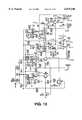
- FIG. 24shows a battery conditioning circuit which may be utilized in place of the central computer controlled charging station of FIG. 23.
- the system of FIG. 24may have a receiving device for a hand-held unit as described in Chadima et al U.S. Pat. No. 3,823,388 (e.g. in reference to the fifth figure thereof at col. 9, lines 20-31). See also a brochure of Norand Corporation entitled “Route Commander" Portable Data System for bakery distribution, No. 960-382-0884, copyright 1984, a copy of two sections thereof being included in Appendix A hereto.
- FIG. 24When a hand-held device indicated at 24-10, FIG. 24, (such as shown in incorporated FIG. 1) is inserted into its receptacle, its charge input indicated at 24-11 is coupled with contact 24-12A, FIG. 24, of the CHARGE output line 24-12, and a further terminal contact 24-13 is coupled with contact 24-14A of the CHG CONTROL line 24-14.
- the receptaclemay receive different hand-held terminals with different battery configurations, and each configuration would provide a characteristic resistance value between the terminal ground contact such as 24-15 (connected with ground contact 24-16A of GND line 24-16) and the terminal charge control contact such as 24-13.
- the terminal resistance valueis thus connected between contact 24-14A and the ground contact 24-16A, and in parallel with a resistor 24-R1 of a charge control reference network 24-20 which further includes resistors 24-R2, 24-R3 and zener 24-Z1.
- the networkreceives an activating potential from a charging supply input line 24-21 (+12 V) via a charging supply potential responsive line 24-21A which is connected between a resistor 24-R4 and a zener 24-Z2.
- the current flow path between the charging supply input line 24-21 and CHARGE output line 24-12includes a charge current sensing resistor 24-R5 and a charge current regulating transistor 24-Q1.
- the value of charge currentis controlled by means of a control circuit 24-22 which includes linear operational amplifiers 24-U1, 24-U2 and 24-U3, transistors 24-Q2 and 24-Q3, resistors 24-R6 through 24-R17, and capacitors 24-C1 and 24-C2.
- the linear operational amplifiersmay receive a supply voltage of plus twelve volts (+12 V) relative to ground potential from supply input 24-21, and may be of type LM2902.
- the charging current supplied by the circuit of FIG. 24will increase for increasing potentials at control point 24-23 up to the limit potential of zener 24-Z1 (which may for example be 1.25 volts).
- the limit potential for zener Z4-Z2is 2.50 volts
- the maximum potential at circuit point 24-24may be designated VR1 with an open circuit between contacts 24-14A and 24-16A. This potential VR1 is then progressively reduced for respective terminal resistance values between about three times the value of 24-R1 (e.g. 5.62 kilohms plus or minus one percent) and about one-third the value of 24-R1, for example.
- Exemplary circuit parameters for FIG. 24are as follows (the letter K standing for kilohms):
- respective different terminals 24-10(such as terminal 10 of incorporated FIG. 1), having respective different charging current requirements are provided with respective corresponding ohmic resistance values between their contacts such as indicated at 24-13 and 24-15, FIG. 24.
- each respective different terminal 24-10will automatically produce the respective required charging current by virtue of the action of control circuit 24-22.
- the potential at 24-24, FIG. 24may be coupled with a central computer system such as 23-71 via an analog to digital converter so as to identify the type of battery means to the central computer.
- the resistance between terminals 24-13 and 24-15would normally be a resistor such as indicated at 24-26 fixedly associated with the battery means such as indicated at 24-27, so that replacing a battery means in a given terminal with a battery means of different ampere-hour capacity would automatically change the resistance value engaged with terminal contacts 24-13, 24-15.
- the computer system 23-71 of FIG. 23 in this modificationwould thus receive an identification of battery capacity along with other battery parameters, and control battery conditioning (e.g. deep discharge) according to relevant parameters including battery capacity, while battery charging would be automatically controlled by a circuit such as shown in FIG. 24.
- component 25-10is a custom control chip for integrating the functions of components 18-10 and 18-28, FIG. 18, into a single monolithic semiconductor element.
- the external path for supplying charging current to battery 25-20includes transistor 25-22, inductor 25-24 and charging current sensing resistor 25-26 which may correspond with components 18-22, 18-24 and 18-26, FIG. 18.
- a pulse width modulated output corresponding to that shown in FIG. 20A,is supplied at VS output 25-27 of chip 25-10 for controlling the on-time of transistor 25-28 which in turn controls the switching action of transistor 25-22.
- Components 25-30, 25-32 and 25-36may essentially correspond with components 18-30, 18-32 and 18-36 in FIG. 18.
- Charging current sensing input 25-38may correspond with input 18-38, FIGS. 18-22, and may control circuitry of chip 25-10 such as represented by components 22-10, 22-14, 22-16 and 22-18, FIG. 22.
- the chip 25-10is shown as sensing battery voltage (+BATT) via a line 25-42 and a first resistance voltage divider 25-43A, 25-43B, and is shown as sensing charging input potential (+CHG) via a line 25-44 and a second resistance voltage divider 25-45A, 25-45B.
- VCCOperating potential is supplied to chip 25-10 from charging input potential (+CHG) via a voltage regulator 25-46.
- Data communicationsmay take place via stage 25-50 for data reception (BPWDATA) and via stage 25-51 for data transmission (BPRDATA).
- BPWDATAdata reception
- BPRDATAdata transmission
- Chip 25-10may control battery discharge conditioning via transistor 25-60.
- FIG. 25The operation of FIG. 25 will be apparent from a consideration of the preceding Description of FIGS. 18, 19, 20A, 20B, 21 and 22.
- FIG. 26shows a preferred form of hand-held terminal unit 26-10 which may be associated with an external conditioning circuit such as shown in FIG. 24 by means of respective sets of mating contacts 26-11, 26-12A; 26-13, 26-14A; 26-15, 26-16A; in the same way as described for FIG. 24.
- Charging currentis supplied to terminal unit 26-10 via CHARGE line 26-12, and an analog charge rate control signal may be applied from terminal unit 26-10 to CHG Control line 26-14, while terminal ground is connected with GND line 26-16 of the conditioning station.
- a charge control reference network 26-20may comprise a resistance network 26-R1, 26-R2 and 26-R3 and a zener 26-Z1 for receiving activating potential from a charging supply input line 26-21 (+12 V) via a charging supply potential responsive line 26-21A.
- a charging current control circuit 26-22may correspond with that of FIG. 24 and controls the charging current supplied via line 26-12 in accordance with a control signal potential at 26-23.
- resistance network 26-20serves as a control signal generating network which provides a default value of control signal at circuit point 26-23 in the absence of any modifying input from a hand-held terminal unit.
- older model terminal unitsmay present an open circuit to station contacts 24-14A, 24-16A or 26-14A, 26-16A, and the generating network 24-20 or 26-20 by itself may provide a default value of control signal which results in the supply of a generally suitable value of charging current at 24-12 or 26-12, say 130 milliamperes.
- the potential at circuit point 26-24may be modified from the default value according to information and programming carried by the terminal unit, for example, to produce a rapid charge rate, a moderate charge rate or a maintenance charge rate in dependence on the battery parameters of the terminal battery means 26-27, ideally so that an optimum charging rate is selected.
- Such charging ratecan in principle take account of the load to be presented to the charging circuit by components of the terminal unit which will be functioning during the charging operation, e.g. terminal circuits for effecting a downloading of data from the memory of the terminal unit.
- the charging current path in FIG. 26may include an optional current regulator 26-28 which is part of the portable terminal unit.
- the current regulator 26-28could be present in cases where the terminal might be charged by means of a charging circuit without the current control features of circuit 26-22.
- current regulator 26-28it is preferred that current regulator 26-28 be unnecessary, (because of the use of a charger configuration such as shown in FIGS. 24 and 26) and therefore preferably current regulator 26-28 is omitted, and line 26-33 is directly connected with contact 26-11.
- the negative terminal of the battery meansis preferably returned directly to ground potential as indicated at 26-30, without the presence of a current sensing resistor such as indicated at 25-26, FIG. 25.
- current sense resistor 24-30, FIG. 24may be short circuited, particularly where the terminal processor means is programmed to accumulate a measure of battery usage. Omission of a current sense resistor such as 24-30 is particularly advantageous where the battery is to supply relatively high peak current as in portable radio frequency (RF) terminals which communicate data on line to a base computer station an RF link.
- RFradio frequency
- battery parameter sensing meansare illustrated, comprised of a temperature transducer 26-32 for obtaining a measure of battery temperature, and a battery potential sensing line 26-33 for sensing battery terminal voltage.
- components 26-34, 26-35, 26-36 and 26-37may be on a single semiconductor chip with processor, timing and memory means 26-40 of the portable unit.
- Components 26-35 and 26-36correspond with components 22-14 and 22-18 of FIG. 22 and comprise battery parameter input means for supplying measures of battery temperature and battery terminal voltage e.g. in binary digital format to the processor and memory components.
- Component 26-40may include the clock-controlled microprocessor corresponding to 22-16, FIG. 22, and the interconnections of FIG. 22 have been omitted in FIG. 26 for simplicity of illustration.
- temperature transducer 26-32may have its signal coupled to a further contact 26-50 via a line 26-51.
- the control circuit 26-22can itself adjust charging current according to battery temperature.
- the presence of a nonzero potential at line 26-51may indicate that operating potential has been applied to transducer 26-32 from a charger circuit. (See, e.g., the specific circuit of FIG. 27.)
- FIG. 27illustrates a new RF terminal unit which may be associated with a non-portable battery conditioning system in a similar way as FIG. 26.
- FIG. 27diagrammatically illustrates an RF terminal system 27-10A which removably receives a rechargeable battery pack 27-10B.
- the rechargeable batteriesmay be contained in a removable drawer as illustrated in pending application of George E. Chadima, Jr., et al, U.S. Ser. No. 104,653 filed Oct. 2, 1987, and entitled “HAND-HELD COMPUTER SYSTEM", and this disclosure is incorporated herein by reference in its entirety.
- an end cap of the RF terminal unitmay be provided with conventional contactors such as indicated at 27-11, 27-13, 27-15, 27-17, 27-19 and 27-21, which provide for quick connection with the battery pack and terminal circuitry simply by placing the terminal assembly into a suitable receptacle, for example, in a delivery vehicle or the like.
- the delivery vehiclemay be provided with a charger circuit such as indicated at 27-22 which may be provided with a conventional terminal unit receptacle similar to that shown in page A2 of Appendix A hereto, which receptacle is provided with contacts for quick release engagement with the terminal contacts 27-11 etc.
- the battery packmay be provided with a rechargeable battery 27-27 and a temperature transducer 27-32, e.g., a solid state type LM335.
- the terminal assembly designated generally 27-10further is indicated as including a resistor 27-R1 and a diode 27-D1 in the battery pack and a corresponding resistor 27-R2 and a corresponding diode 27-D2 in the terminal itself.
- the potential across transducer 27-32will be zero until such time as a charge potential is applied at contact 27-11, so that the presence of a potential different from zero volts at contact 27-17 and at line 27-33 will indicate application of charging potential to the assembly 27-10.
- the circuitry at 27-35A and 27-35B in FIG. 27may correspond with the circuitry 26-34 and 26-35 in FIG.
- 26may represent a suitable commercially available integrated circuit for sensing analog values of battery terminal voltage and temperature, and for supplying corresponding digital values to a terminal processor such as indicated at 26-40 in FIG. 26.
- Component 27-37 in FIG. 27may correspond with components 26-36 and 26-37 in FIG. 26 and may receive an output control word from a processor corresponding to 26-40 in FIG. 26 for establishing a desired control signal potential at contact 27-13 as described in detail with reference to FIG. 26.
- the processor circuit of FIG. 27may be provided with a local area network (LAN) interface 27-39 for communication with exterior devices via contacts 27-19 and 27-21, for example.
- LANlocal area network
- the terminal 27-10Ais not only provided with RF circuitry and antenna means for on-line data interchange with a RF base station, but further the plug-in contacting of the terminal body at 27-19 and 27-21 provides for batch type transmission between the terminal 27-10 and an exterior station, 27, permitting the batch type downloading of data, for example programming, into the terminal 27-10, and the batch type uploading of stored data from the terminal to an external station, for example a printer of a vehicle such as previously mentioned.
- the incorporated patent application Ser. No. 104,653shows in the tenth figure a fifteen pin "D" subminiature connector. Certain pins of this connector are indicated at 27-47 through 27-52 in FIG. 27, so that the terminal 27-10 can be coupled by means of such connector with a charger circuit such as indicated at 27-60, for example by means of a suitable connecting cable or the like.
- the charger circuit 27-60may correspond with the charger circuit of FIG. 24 or FIG. 26, for example, and may include components connected to the local area network interface 27-39 via contacts 27-51 and 27-52.
- the local area network interface 27-39may be utilized to transmit to the charger 27-22 or 27-60 battery information such as rated battery capacity and hours of use subsequent to a previous charge as explained in detail with respect to FIGS. 23 and 26.
- the processor of components 23-71, 25-10, 26-40 or of FIG. 27can be programmed with a schedule of battery charging currents as a function of temperature such as described with reference to FIGS. 18-22.
- a schedule of battery charging currentsas a function of temperature such as described with reference to FIGS. 18-22.
- the charging ratecan be adjusted according to a quantitative measure of battery temperature so as to achieve a maximum charging rate consistent with the specific characteristics of the battery means 23-20, 25-20, 26-27 or 27-27.
- abnormally high or low valuesmay represent a defective battery or short circuit, so that the processor of component 23-71, 25-10, 26-40, or of FIG. 27 would be programmed to provide a shutoff control potential for the charging circuit.
- a maximum potential from the converter channel 26-37could establish a control potential at circuit point 26-23 of 1.25 volts, the limit potential of zener 26-Z1, and produce zero charging current (corresponding to a shut-off of transistor 24-Q1, FIG. 24).
- FIG. 26, or of FIG. 27keeps track of usage of the hand-held terminal unit in the portable (off the charger) mode
- the accumulated hours of use along with rated battery capacitycan be transmitted to the central computer system 23-71 at the start of a conditioning operation, or can be utilized in selecting a suitable computer generated control word for register 26-36 in FIG. 26 or for component 27-37, FIG. 27.
- the processor e g. of 26-40may increment an elapsed time counter (e.g.
- each portable terminal unitmay store battery information such as indicated in TABLE B of incorporated U.S. Pat. No. 4,553,081 (col. 14, line 40-col. 15, line 58), and battery information may be transmitted to an external processor e.g. of component 23-71, FIG. 23, when the terminal unit is plugged into a conditioning station preparatory to conditioning operation, and in any case the stored data may be used as battery information in the generation of charging current control signals, e.g., in the embodiments of FIGS. 23, 25, 26 and 27.
- communication between a processor, e.g., of components 18-10, 23-82, 25-10, 26-40, or of FIG. 27, and an external stationmay include the types of commands given in TABLE A of incorporated U.S. Pat. No. 4,553,081 (col. 14, lines 14-39).
- FIGS. 1-12flowcharts, timing diagrams and an exemplary lookup table, suitable for the processor of a portable terminal unit such as processor 14 of FIGS. 1-12, or of 18-10, FIG. 18, or of 26-40, FIG. 26, or of FIG. 27, and also suitable for a central processor such a 21-71, FIG. 23, are shown in APPENDIX B hereto (pages B1 to B10 following the ABSTRACT OF THE DISCLOSURE). This information was generated for the battery processor 140, FIG. 9B, but was not originally included since it was not considered to be required for practicing this mode of the invention.
- FIGS. 18, 19, 20A, 20B, and 21-27the system of FIGS. 18-22 or 25 may form a part of a stationary battery charging system which removably receives spare battery packs, and/or which removably receives hand-held units such as shown in FIG. 1.
- the processor means 18-10 or 25-10 as the main processor of a hand-held terminal unitmay measure actual battery discharge current during use of the hand-held unit and then control the duration of recharging according to such measure, and/or according to rated battery capacity as stored in a read only memory of the main processor, or the like.
- a number of electrochemical cells 28-2are arranged in series to provide a predetermined voltage for powering a particular utilization device (not shown).
- the electrochemical cells 28-2are nickel-metal hydride cells of the type generally used for portable electronic equipment.
- the electrochemical cellsmay be nickel-cadmium cells, lithium-ion cells, or the like.
- five cellsmay be electrically arranged in series resulting in a positive battery voltage terminal BATT+ and a negative battery voltage terminal BATT-.
- An electronic memory device 28-4receives power from the electrochemical cells.
- the electronic memory device 28-4is capable of storing information of the particular history of the battery pack 28-8 which may be later retrieved and acted upon accordingly by a utilization device.
- the electronic memory device 28-4may store identification information such as manufacturer, date of manufacture, date of sale, serial number, type of electrochemical cells, chain of title from manufacturer to buyer, etc. for tagging and identifying that individual battery pack 28-8. Such information may be useful for example to trace the origin of defects or to determine the age of the battery pack, for example.
- Information as to the actual charging and discharging characteristics of the battery pack 28-8may also be stored for determining the amount of available capacity remaining in the battery pack 28-8 or for optimizing recharging algorithms.
- the battery pack 28-8 historymay include information such as maximum available capacity, remaining capacity, the total number of charge/discharge cycles the battery pack 28-8 has experienced, the number of charge/discharge cycles since a conditioning cycle, particular charge/discharge characteristics of the battery pack 28-8, battery temperature, or the like.
- the actual physical characteristics of the electrochemical cellsmay thus be monitored and stored in the electronic memory device and retrieved by the utilization device to effectively manage and employ the energy stored in the battery pack 28-8.
- An ideal electronic memory device 28-4consumes little or no power, is reliable, and is manufactured in a small package.
- the electronic memory device 28-4may be a Dallas Semiconductor DS2434 Battery Identification Chip.
- the DS2434is manufactured in a 3 lead TO-92 package having two power leads and a 1-wire data interface lead.
- the DS2434has 96 bytes of random access memory (RAM) and 32 bytes of nonvolatile EEPROM memory available for battery storage, includes a digital temperature sensor, and operates at low power.
- a utilization devicemay access the battery pack 28-8 data stored in the electronic memory device through the 1-wire interface at communications line BATT -- DATA.
- Operational power of the electronic memory device 28-4may be supplied by the electrochemical cells 28-2 when the battery pack 28-8 is charged or by an external power source during charging.
- the nonvolatile memory of the electronic memory device 28-4allows for retention of stored data in the event that the battery pack 28-8 is completely depleted.
- the electronic memory device 28-8may be powered by fewer than the total number of electrochemical cells 28-2 in the battery pack 28-8 when the total series voltage from the entirety of the electrochemical cells 28-2 exceeds the maximum operating voltage of the electronic memory device.
- the electronic memory device 28-6may be powered by three of the electrochemical cells 28-2 by tapping an intermediate voltage point in the battery pack 28-8.
- a voltage clamping component 28-6may be utilized to protect the memory device 28-6 from accidental loss of stored memory states due to electrostatic discharge. For example an operator may touch communications terminal BATT -- DATA during installation of the battery pack 28-8 into a utilization device and inadvertently apply an electrostatic discharge through the communications terminal BATT -- DATA to the electronic memory device 28-4 thereby destroying the stored memory states and causing a loss of the stored battery pack 28-8 data.
- the voltage clamping component 28-6may be an AVX Transguard type component connected between communications line BATT -- DATA and negative terminal BATT- of the battery pack 28-8 which is typically a ground reference. The voltage clamping component 28-6 clamps any high voltage transient occurring at the BATT -- DATA terminal in order to prevent damage to the electronic memory device 28-4.
- FIG. 29depicts a physical configuration of the battery pack 29-8 as manufactured.
- the battery pack 29-8may be assembled using the process normally employed to assemble rechargeable battery packs wherein thin metal straps 29-10 are spot welded to the electrochemical cells 29-2 to interconnect the electrochemical cells 29-2.
- Using standard battery pack assembly techniquesprovides reliable low impedance and low cost connections within the battery pack 29-8. No circuit board nor any other components which may increase manufacture costs and reduce the reliability of the connections are needed to assemble the battery pack 29-8.
- Communications line BATT -- DATArequires a large area contact pad as shown in FIG. 29 for optimum signal integrity.
- the straps 29-10may be comprised of individual pieces of metal and may be placed on an insulating substrate to hold them in the proper orientation for assembly. Metal pieces 29-10 may be formed by chemical etching from a single sheet of material which may consist of a traditional flexible circuit or an equivalent thereof.
- the spot welding processmay be a possible source of damage to the electronic memory device 29-4 due to the application of a potentially damaging high voltage on the pins of the electronic memory device 29-4 by the spot welder.
- the potentially damaging effects of spot welding to the electronic memory device 29-4may be mitigated or eliminated by assembling the voltage clamping 29-6 device to the battery pack 29-8 assembly prior to attaching the electronic memory device.
- the electronic memory device 29-4 and the voltage clamping component 29-6may be affixed to metal conductors 29-10 using a traditional electrical connection technique such as soldering before the spot weld is applied.
- metal conductors 29-10may be mechanically clamped to a low electrical potential point such that no damaging voltage will be applied to the pins of the electronic memory device.
Landscapes
- Engineering & Computer Science (AREA)
- Power Engineering (AREA)
- Chemical Kinetics & Catalysis (AREA)
- Chemical & Material Sciences (AREA)
- Electrochemistry (AREA)
- General Chemical & Material Sciences (AREA)
- Manufacturing & Machinery (AREA)
- Theoretical Computer Science (AREA)
- Microelectronics & Electronic Packaging (AREA)
- Physics & Mathematics (AREA)
- General Engineering & Computer Science (AREA)
- General Physics & Mathematics (AREA)
- Business, Economics & Management (AREA)
- Emergency Management (AREA)
- Charge And Discharge Circuits For Batteries Or The Like (AREA)
Abstract
Description
______________________________________ Exemplary Table Of Desired Average Battery Charging Current As A Function Of Temperature (See FIG. 6.) Temperature Average Battery Corresponding Range (° F.) Charging Current Nominal n Value ______________________________________ Below 2.5 Zero 0 2.5 to 35 1 35 to 76 5 76 to 98 10 98 to 112.5 C/6.7 15 Over 112.5 Zero 0 ______________________________________
______________________________________ Component Corresponding Component of FIG. 23 or Components of FIG. 5 ______________________________________ Battery System 23-18Components 20, 81-83, and 91-93 Rechargeable Battery Rechargeable Battery Means 23-20Means 20 Memory and Battery Processor, Timing Communications Means andMemory Circuits 82, 23-82Digital Interface 81 and Voltage Regulator and ResetComponent 83Battery Voltage Component 91 Monitor 23-91Battery Current Component 92 Monitor 23-92Battery Temperature Component 93 Monitor 23-93 ______________________________________
______________________________________ Exemplary Circuit Parameters, FIG. 24 ______________________________________ 24-U1, 24-U2, 24-U3 Type LM2902 24-Q1 power transistor 24-Q2, 24-Q3 Type 2N3904 24-R1 5.62K (1%) 24-R2 100K (1%) 24-R3 10K 24-R4 4.7K 24-R5 one ohm (1%) 24-R6 one kilohm (1K) 24-R7, 24-R8, 24-R9, 24-R10 10K (.1%) 24-R11, 24-R12 10K 24-R13, 24-R14 one kilohm (1K) 24-R15 820 ohms 24-R16 30.1K (1%) 24-R17 10K (1%) 24-C1, 24-C2 .1 microfarad 24-Z1 LM385BZ (1.25 volts) 24-Z2 LM385BZ (2.50 ______________________________________ volts)
Claims (42)
Priority Applications (4)
| Application Number | Priority Date | Filing Date | Title |
|---|---|---|---|
| US09/270,302US6075340A (en) | 1985-11-12 | 1999-03-15 | Battery pack having memory |
| US09/513,216US6252380B1 (en) | 1984-05-21 | 2000-02-24 | Battery pack having memory |
| US09/513,290US6271643B1 (en) | 1986-12-18 | 2000-02-24 | Battery pack having memory |
| US09/855,748US20020101218A1 (en) | 1984-05-21 | 2001-05-14 | Battery pack having memory |
Applications Claiming Priority (11)
| Application Number | Priority Date | Filing Date | Title |
|---|---|---|---|
| US06/797,235US4716354A (en) | 1985-11-12 | 1985-11-12 | Automatic voltage regulator means providing a dual low power responsive and output-voltage-controlling regulator signal particularly for a plural source battery powered system |
| US06/876,194US4709202A (en) | 1982-06-07 | 1986-06-19 | Battery powered system |
| US06/944,503US4737702A (en) | 1982-06-07 | 1986-12-18 | Battery charging control system particularly for hand held device |
| US07/168,352US4885523A (en) | 1988-03-15 | 1988-03-15 | Battery conditioning system having communication with battery parameter memory means in conjunction with battery conditioning |
| US07/422,226US4961043A (en) | 1988-03-15 | 1989-10-16 | Battery conditioning system having communication with battery parameter memory means in conjunction with battery conditioning |
| US54423090A | 1990-06-29 | 1990-06-29 | |
| US07/769,337US5278487A (en) | 1988-03-15 | 1991-10-01 | Battery conditioning system having communication with battery parameter memory means in conjunction with battery conditioning |
| US08/134,881US5508599A (en) | 1988-03-15 | 1993-10-12 | Battery conditioning system having communication with battery parameter memory means in conjunction with battery conditioning |
| US08/415,075US5619117A (en) | 1982-06-07 | 1995-03-30 | Battery pack having memory |
| US08/841,974US5883493A (en) | 1982-06-07 | 1997-04-08 | Battery pack having memory |
| US09/270,302US6075340A (en) | 1985-11-12 | 1999-03-15 | Battery pack having memory |
Related Parent Applications (1)
| Application Number | Title | Priority Date | Filing Date |
|---|---|---|---|
| US08/841,974ContinuationUS5883493A (en) | 1982-06-07 | 1997-04-08 | Battery pack having memory |
Related Child Applications (2)
| Application Number | Title | Priority Date | Filing Date |
|---|---|---|---|
| US09/513,216ContinuationUS6252380B1 (en) | 1984-05-21 | 2000-02-24 | Battery pack having memory |
| US09/513,290ContinuationUS6271643B1 (en) | 1986-12-18 | 2000-02-24 | Battery pack having memory |
Publications (1)
| Publication Number | Publication Date |
|---|---|
| US6075340Atrue US6075340A (en) | 2000-06-13 |
Family
ID=27581050
Family Applications (2)
| Application Number | Title | Priority Date | Filing Date |
|---|---|---|---|
| US09/270,302Expired - Fee RelatedUS6075340A (en) | 1984-05-21 | 1999-03-15 | Battery pack having memory |
| US09/513,216Expired - Fee RelatedUS6252380B1 (en) | 1984-05-21 | 2000-02-24 | Battery pack having memory |
Family Applications After (1)
| Application Number | Title | Priority Date | Filing Date |
|---|---|---|---|
| US09/513,216Expired - Fee RelatedUS6252380B1 (en) | 1984-05-21 | 2000-02-24 | Battery pack having memory |
Country Status (1)
| Country | Link |
|---|---|
| US (2) | US6075340A (en) |
Cited By (28)
| Publication number | Priority date | Publication date | Assignee | Title |
|---|---|---|---|---|
| WO2002014960A3 (en)* | 2000-08-11 | 2002-10-10 | Seiko Epson Corp | Electronic apparatus and method of controlling the electronic apparatus |
| US6617829B1 (en) | 2002-01-14 | 2003-09-09 | Gateway, Inc. | Automatic conditioning of battery in battery-powered apparatus |
| US20050134225A1 (en)* | 2003-12-23 | 2005-06-23 | International Business Machines Corporation | Smart battery charging system, method, and computer program product |
| EP1657622A1 (en)* | 2004-11-12 | 2006-05-17 | Hewlett-Packard Development Company, L.P. | Power management system and method |
| US20060176020A1 (en)* | 2005-01-06 | 2006-08-10 | Electritek-Avt, Inc. | Discharge circuit |
| US7160113B2 (en) | 2000-08-01 | 2007-01-09 | Earthwalk Communication, Inc. | Mobile teaching system |
| US20070096689A1 (en)* | 2005-10-27 | 2007-05-03 | Wozniak John A | Battery analysis system and method |
| US20070236183A1 (en)* | 2006-03-31 | 2007-10-11 | Valence Technology, Inc. | Battery charge indication methods, battery charge monitoring devices, rechargeable batteries, and articles of manufacture |
| USD555586S1 (en) | 2005-06-27 | 2007-11-20 | Mcconnell Evan T | Battery housing |
| US20070290653A1 (en)* | 2005-01-06 | 2007-12-20 | Electritek-Avt, Inc. | Buttonless Battery Charger Interface |
| EP2571136A1 (en)* | 2011-09-13 | 2013-03-20 | Panasonic Corporation | Power supply device |
| US20130234673A1 (en)* | 2012-03-08 | 2013-09-12 | Hon Hai Precision Industry Co., Ltd. | Discharge circuit |
| US20140125277A1 (en)* | 2012-11-08 | 2014-05-08 | Ford Global Technologies, Llc | System and method for reducing thermal conditions during wireless charging |
| US20140372056A1 (en)* | 2013-06-12 | 2014-12-18 | Infineon Technologies Ag | Method and Device for Determining a Parameter of a Model of a Technical Installation |
| US20150062765A1 (en)* | 2013-08-27 | 2015-03-05 | GM Global Technology Operations LLC | Resettable circuit protection system and vehicle with same |
| US9124124B2 (en) | 2012-10-16 | 2015-09-01 | Ford Global Technologies, Llc | System and method for reducing interference during wireless charging |
| US9148033B2 (en) | 2012-12-21 | 2015-09-29 | Ford Global Technologies, Llc | System of securing a wide-range of devices during wireless charging |
| EP2983238A4 (en)* | 2013-03-22 | 2016-08-17 | Sony Corp | Management device, communication device, management method, and management system |
| US9455596B2 (en) | 2012-10-16 | 2016-09-27 | Ford Global Technologies, Llc | System and method for reducing interference between wireless charging and amplitude modulation reception |
| US9472963B2 (en) | 2013-02-06 | 2016-10-18 | Ford Global Technologies, Llc | Device for wireless charging having a plurality of wireless charging protocols |
| US20170294790A1 (en)* | 2015-09-22 | 2017-10-12 | Guangdong Oppo Mobile Telecommunications Corp., Ltd. | Charge control method and device, and electronic device |
| CN107710552A (en)* | 2016-02-05 | 2018-02-16 | 广东欧珀移动通信有限公司 | Adapter and charge control method |
| US9917457B2 (en) | 2015-02-02 | 2018-03-13 | Black & Decker Inc. | Power tool with USB connection |
| EP3282551A4 (en)* | 2016-02-05 | 2018-05-23 | Guangdong Oppo Mobile Telecommunications Corp., Ltd. | Adapter and charging control method |
| US20180226811A1 (en)* | 2014-10-21 | 2018-08-09 | Toshiba Mitsubishi-Electric Industrial Systems Corporation | Storage battery system |
| US11448703B2 (en)* | 2018-02-07 | 2022-09-20 | Lg Energy Solution, Ltd. | Device and method for estimating SOC via open-circuit voltage of battery |
| US20230268753A1 (en)* | 2022-02-21 | 2023-08-24 | Lenovo (United States) Inc. | Intelligent battery charging based on history |
| RU236545U1 (en)* | 2025-05-19 | 2025-08-12 | Общество С Ограниченной Ответственностью "Геодарт" | BATTERY MODULE |
Families Citing this family (109)
| Publication number | Priority date | Publication date | Assignee | Title |
|---|---|---|---|---|
| US7126450B2 (en) | 1999-06-21 | 2006-10-24 | Access Business Group International Llc | Inductively powered apparatus |
| US7212414B2 (en)* | 1999-06-21 | 2007-05-01 | Access Business Group International, Llc | Adaptive inductive power supply |
| US7385357B2 (en)* | 1999-06-21 | 2008-06-10 | Access Business Group International Llc | Inductively coupled ballast circuit |
| US7522878B2 (en)* | 1999-06-21 | 2009-04-21 | Access Business Group International Llc | Adaptive inductive power supply with communication |
| US6825620B2 (en) | 1999-06-21 | 2004-11-30 | Access Business Group International Llc | Inductively coupled ballast circuit |
| US7518267B2 (en)* | 2003-02-04 | 2009-04-14 | Access Business Group International Llc | Power adapter for a remote device |
| US7612528B2 (en)* | 1999-06-21 | 2009-11-03 | Access Business Group International Llc | Vehicle interface |
| CA2328539A1 (en) | 2000-12-13 | 2002-06-13 | Leonard G. D. Allen | Solar powered surveillance monitor |
| KR100566220B1 (en)* | 2001-01-05 | 2006-03-29 | 삼성전자주식회사 | Solid state battery charger |
| JP2002315198A (en)* | 2001-04-17 | 2002-10-25 | Makita Corp | Battery drive equipment |
| US6456037B1 (en) | 2001-07-18 | 2002-09-24 | Motorola Inc. | Battery charger and method to recall last charge state |
| US7107160B2 (en) | 2001-10-09 | 2006-09-12 | Hewlett-Packard Development Company, L.P. | Use-adaptive fuel gauging for battery powered electronic devices |
| US7573159B1 (en) | 2001-10-22 | 2009-08-11 | Apple Inc. | Power adapters for powering and/or charging peripheral devices |
| WO2003036777A1 (en)* | 2001-10-22 | 2003-05-01 | Apple Computer, Inc. | Methods and apparatus for charging a battery in a peripheral device |
| US6859013B2 (en)* | 2002-04-03 | 2005-02-22 | Black & Decker Inc. | Battery charger with protection circuitry |
| US7701172B2 (en)* | 2003-10-14 | 2010-04-20 | Black & Decker Inc. | Power driver and charger with flexible mounting system for battery pack |
| US7634605B2 (en)* | 2004-04-27 | 2009-12-15 | Apple Inc. | Method and system for transferring stored data between a media player and an accessory |
| US7529871B1 (en) | 2004-04-27 | 2009-05-05 | Apple Inc. | Communication between an accessory and a media player with multiple protocol versions |
| US7529872B1 (en) | 2004-04-27 | 2009-05-05 | Apple Inc. | Communication between an accessory and a media player using a protocol with multiple lingoes |
| US7526588B1 (en) | 2004-04-27 | 2009-04-28 | Apple Inc. | Communication between an accessory and a media player using a protocol with multiple lingoes |
| US7895378B2 (en) | 2004-04-27 | 2011-02-22 | Apple Inc. | Method and system for allowing a media player to transfer digital audio to an accessory |
| US8117651B2 (en) | 2004-04-27 | 2012-02-14 | Apple Inc. | Method and system for authenticating an accessory |
| US7797471B2 (en) | 2004-04-27 | 2010-09-14 | Apple Inc. | Method and system for transferring album artwork between a media player and an accessory |
| US7441058B1 (en) | 2006-09-11 | 2008-10-21 | Apple Inc. | Method and system for controlling an accessory having a tuner |
| US7529870B1 (en) | 2004-04-27 | 2009-05-05 | Apple Inc. | Communication between an accessory and a media player with multiple lingoes |
| US7441062B2 (en) | 2004-04-27 | 2008-10-21 | Apple Inc. | Connector interface system for enabling data communication with a multi-communication device |
| US7826318B2 (en) | 2004-04-27 | 2010-11-02 | Apple Inc. | Method and system for allowing a media player to transfer digital audio to an accessory |
| US7673083B2 (en)* | 2004-04-27 | 2010-03-02 | Apple Inc. | Method and system for controlling video selection and playback in a portable media player |
| US7581119B2 (en)* | 2004-07-18 | 2009-08-25 | Apple Inc. | Method and system for discovering a power source on a peripheral bus |
| US7462951B1 (en) | 2004-08-11 | 2008-12-09 | Access Business Group International Llc | Portable inductive power station |
| US7408324B2 (en)* | 2004-10-27 | 2008-08-05 | Access Business Group International Llc | Implement rack and system for energizing implements |
| US7541776B2 (en) | 2004-12-10 | 2009-06-02 | Apple Inc. | Method and system for operating a portable electronic device in a power-limited manner |
| US7823214B2 (en)* | 2005-01-07 | 2010-10-26 | Apple Inc. | Accessory authentication for electronic devices |
| US7525216B2 (en)* | 2005-01-07 | 2009-04-28 | Apple Inc. | Portable power source to provide power to an electronic device via an interface |
| GB2426390B (en)* | 2005-05-17 | 2009-02-18 | Milwaukee Electric Tool Corp | Power tool, battery, charger and method of operating the same |
| DE102006023187B4 (en) | 2005-05-17 | 2020-02-27 | Milwaukee Electric Tool Corp. | Method for operating a battery charger and a combination comprising a battery and a battery charger |
| JP4764144B2 (en)* | 2005-11-18 | 2011-08-31 | 株式会社東芝 | Information processing apparatus and processor control method |
| US7710078B2 (en)* | 2006-01-05 | 2010-05-04 | Pine Valley Investments, Inc. | Battery charger with temperature compensation |
| US7848527B2 (en) | 2006-02-27 | 2010-12-07 | Apple Inc. | Dynamic power management in a portable media delivery system |
| US8086332B2 (en)* | 2006-02-27 | 2011-12-27 | Apple Inc. | Media delivery system with improved interaction |
| US7770036B2 (en)* | 2006-02-27 | 2010-08-03 | Apple Inc. | Power management in a portable media delivery system |
| USD562226S1 (en) | 2006-05-17 | 2008-02-19 | Milwaukee Electric Tool Corporation | Power tool battery |
| US8006019B2 (en) | 2006-05-22 | 2011-08-23 | Apple, Inc. | Method and system for transferring stored data between a media player and an accessory |
| US7415563B1 (en) | 2006-06-27 | 2008-08-19 | Apple Inc. | Method and system for allowing a media player to determine if it supports the capabilities of an accessory |
| JP5228322B2 (en)* | 2006-08-30 | 2013-07-03 | トヨタ自動車株式会社 | Power storage device deterioration evaluation system, vehicle, power storage device deterioration evaluation method, and computer-readable recording medium storing a program for causing a computer to execute the deterioration evaluation method |
| US7558894B1 (en) | 2006-09-11 | 2009-07-07 | Apple Inc. | Method and system for controlling power provided to an accessory |
| US8001400B2 (en)* | 2006-12-01 | 2011-08-16 | Apple Inc. | Power consumption management for functional preservation in a battery-powered electronic device |
| TW200845461A (en)* | 2007-05-04 | 2008-11-16 | Iwei Technology Co Ltd | Recharging apparatus with battery capacity analyzing function |
| EP2185992B1 (en)* | 2007-09-04 | 2013-07-17 | Apple Inc. | Smart dock for chaining accessories |
| CN101910968A (en)* | 2008-01-07 | 2010-12-08 | 捷通国际有限公司 | Wireless power adapter for computer |
| US8047966B2 (en)* | 2008-02-29 | 2011-11-01 | Apple Inc. | Interfacing portable media devices and sports equipment |
| US8756440B2 (en)* | 2008-04-16 | 2014-06-17 | International Business Machines Corporation | System power capping using information received from the installed power supply |
| US8498763B2 (en)* | 2008-06-16 | 2013-07-30 | International Business Machines Corporation | Maintaining energy principal preferences in a vehicle |
| US8266075B2 (en) | 2008-06-16 | 2012-09-11 | International Business Machines Corporation | Electric vehicle charging transaction interface for managing electric vehicle charging transactions |
| US20090313034A1 (en)* | 2008-06-16 | 2009-12-17 | International Business Machines Corporation | Generating Dynamic Energy Transaction Plans |
| US9751416B2 (en)* | 2008-06-16 | 2017-09-05 | International Business Machines Corporation | Generating energy transaction plans |
| US8531162B2 (en)* | 2008-06-16 | 2013-09-10 | International Business Machines Corporation | Network based energy preference service for managing electric vehicle charging preferences |
| US20090313174A1 (en)* | 2008-06-16 | 2009-12-17 | International Business Machines Corporation | Approving Energy Transaction Plans Associated with Electric Vehicles |
| US20090313032A1 (en)* | 2008-06-16 | 2009-12-17 | International Business Machines Corporation | Maintaining Energy Principal Preferences for a Vehicle by a Remote Preferences Service |
| US7991665B2 (en)* | 2008-06-16 | 2011-08-02 | International Business Machines Corporation | Managing incentives for electric vehicle charging transactions |
| US20100049533A1 (en)* | 2008-08-19 | 2010-02-25 | International Business Machines Corporation | Executing an Energy Transaction Plan for an Electric Vehicle |
| US8725551B2 (en)* | 2008-08-19 | 2014-05-13 | International Business Machines Corporation | Smart electric vehicle interface for managing post-charge information exchange and analysis |
| US8918376B2 (en)* | 2008-08-19 | 2014-12-23 | International Business Machines Corporation | Energy transaction notification service for presenting charging information of an electric vehicle |
| US8918336B2 (en)* | 2008-08-19 | 2014-12-23 | International Business Machines Corporation | Energy transaction broker for brokering electric vehicle charging transactions |
| US8103391B2 (en)* | 2008-08-19 | 2012-01-24 | International Business Machines Corporation | System for detecting interrupt conditions during an electric vehicle charging process |
| US8208853B2 (en) | 2008-09-08 | 2012-06-26 | Apple Inc. | Accessory device authentication |
| US8238811B2 (en) | 2008-09-08 | 2012-08-07 | Apple Inc. | Cross-transport authentication |
| US20110164471A1 (en)* | 2010-01-05 | 2011-07-07 | Access Business Group International Llc | Integrated wireless power system |
| US8438408B2 (en)* | 2010-01-26 | 2013-05-07 | Apple Inc. | Control of accessory components by portable computing device |
| US8841881B2 (en) | 2010-06-02 | 2014-09-23 | Bryan Marc Failing | Energy transfer with vehicles |
| US10824330B2 (en) | 2011-04-22 | 2020-11-03 | Emerging Automotive, Llc | Methods and systems for vehicle display data integration with mobile device data |
| US9285944B1 (en) | 2011-04-22 | 2016-03-15 | Angel A. Penilla | Methods and systems for defining custom vehicle user interface configurations and cloud services for managing applications for the user interface and learned setting functions |
| US10289288B2 (en) | 2011-04-22 | 2019-05-14 | Emerging Automotive, Llc | Vehicle systems for providing access to vehicle controls, functions, environment and applications to guests/passengers via mobile devices |
| US9230440B1 (en) | 2011-04-22 | 2016-01-05 | Angel A. Penilla | Methods and systems for locating public parking and receiving security ratings for parking locations and generating notifications to vehicle user accounts regarding alerts and cloud access to security information |
| US9648107B1 (en) | 2011-04-22 | 2017-05-09 | Angel A. Penilla | Methods and cloud systems for using connected object state data for informing and alerting connected vehicle drivers of state changes |
| US9180783B1 (en) | 2011-04-22 | 2015-11-10 | Penilla Angel A | Methods and systems for electric vehicle (EV) charge location color-coded charge state indicators, cloud applications and user notifications |
| US11370313B2 (en) | 2011-04-25 | 2022-06-28 | Emerging Automotive, Llc | Methods and systems for electric vehicle (EV) charge units and systems for processing connections to charge units |
| US11270699B2 (en) | 2011-04-22 | 2022-03-08 | Emerging Automotive, Llc | Methods and vehicles for capturing emotion of a human driver and customizing vehicle response |
| US9536197B1 (en) | 2011-04-22 | 2017-01-03 | Angel A. Penilla | Methods and systems for processing data streams from data producing objects of vehicle and home entities and generating recommendations and settings |
| US9493130B2 (en) | 2011-04-22 | 2016-11-15 | Angel A. Penilla | Methods and systems for communicating content to connected vehicle users based detected tone/mood in voice input |
| US11203355B2 (en) | 2011-04-22 | 2021-12-21 | Emerging Automotive, Llc | Vehicle mode for restricted operation and cloud data monitoring |
| US12337716B2 (en) | 2011-04-22 | 2025-06-24 | Emerging Automotive, Llc | Systems for transferring user profiles between vehicles using cloud services |
| US9581997B1 (en) | 2011-04-22 | 2017-02-28 | Angel A. Penilla | Method and system for cloud-based communication for automatic driverless movement |
| US9139091B1 (en) | 2011-04-22 | 2015-09-22 | Angel A. Penilla | Methods and systems for setting and/or assigning advisor accounts to entities for specific vehicle aspects and cloud management of advisor accounts |
| US9809196B1 (en) | 2011-04-22 | 2017-11-07 | Emerging Automotive, Llc | Methods and systems for vehicle security and remote access and safety control interfaces and notifications |
| US9171268B1 (en) | 2011-04-22 | 2015-10-27 | Angel A. Penilla | Methods and systems for setting and transferring user profiles to vehicles and temporary sharing of user profiles to shared-use vehicles |
| US9229905B1 (en) | 2011-04-22 | 2016-01-05 | Angel A. Penilla | Methods and systems for defining vehicle user profiles and managing user profiles via cloud systems and applying learned settings to user profiles |
| US9963145B2 (en) | 2012-04-22 | 2018-05-08 | Emerging Automotive, Llc | Connected vehicle communication with processing alerts related to traffic lights and cloud systems |
| US9104537B1 (en) | 2011-04-22 | 2015-08-11 | Angel A. Penilla | Methods and systems for generating setting recommendation to user accounts for registered vehicles via cloud systems and remotely applying settings |
| US9215274B2 (en) | 2011-04-22 | 2015-12-15 | Angel A. Penilla | Methods and systems for generating recommendations to make settings at vehicles via cloud systems |
| US9348492B1 (en) | 2011-04-22 | 2016-05-24 | Angel A. Penilla | Methods and systems for providing access to specific vehicle controls, functions, environment and applications to guests/passengers via personal mobile devices |
| US9371007B1 (en) | 2011-04-22 | 2016-06-21 | Angel A. Penilla | Methods and systems for automatic electric vehicle identification and charging via wireless charging pads |
| US9346365B1 (en) | 2011-04-22 | 2016-05-24 | Angel A. Penilla | Methods and systems for electric vehicle (EV) charging, charging unit (CU) interfaces, auxiliary batteries, and remote access and user notifications |
| US9288270B1 (en) | 2011-04-22 | 2016-03-15 | Angel A. Penilla | Systems for learning user preferences and generating recommendations to make settings at connected vehicles and interfacing with cloud systems |
| US10572123B2 (en) | 2011-04-22 | 2020-02-25 | Emerging Automotive, Llc | Vehicle passenger controls via mobile devices |
| US9123035B2 (en) | 2011-04-22 | 2015-09-01 | Angel A. Penilla | Electric vehicle (EV) range extending charge systems, distributed networks of charge kiosks, and charge locating mobile apps |
| US10286919B2 (en) | 2011-04-22 | 2019-05-14 | Emerging Automotive, Llc | Valet mode for restricted operation of a vehicle and cloud access of a history of use made during valet mode use |
| US11294551B2 (en) | 2011-04-22 | 2022-04-05 | Emerging Automotive, Llc | Vehicle passenger controls via mobile devices |
| US9818088B2 (en) | 2011-04-22 | 2017-11-14 | Emerging Automotive, Llc | Vehicles and cloud systems for providing recommendations to vehicle users to handle alerts associated with the vehicle |
| US11132650B2 (en) | 2011-04-22 | 2021-09-28 | Emerging Automotive, Llc | Communication APIs for remote monitoring and control of vehicle systems |
| US9365188B1 (en) | 2011-04-22 | 2016-06-14 | Angel A. Penilla | Methods and systems for using cloud services to assign e-keys to access vehicles |
| US9189900B1 (en) | 2011-04-22 | 2015-11-17 | Angel A. Penilla | Methods and systems for assigning e-keys to users to access and drive vehicles |
| US9697503B1 (en) | 2011-04-22 | 2017-07-04 | Angel A. Penilla | Methods and systems for providing recommendations to vehicle users to handle alerts associated with the vehicle and a bidding market place for handling alerts/service of the vehicle |
| US10217160B2 (en)* | 2012-04-22 | 2019-02-26 | Emerging Automotive, Llc | Methods and systems for processing charge availability and route paths for obtaining charge for electric vehicles |
| US8880367B1 (en)* | 2011-11-10 | 2014-11-04 | Energy Pass Incorporation | Method for accurately performing power estimation on a battery of an electronic device, and associated apparatus |
| US9083202B2 (en) | 2012-12-18 | 2015-07-14 | Fca Us Llc | Alternator control for battery charging |
| US20190219638A1 (en)* | 2018-01-17 | 2019-07-18 | S. C. Johnson & Son, Inc. | Electronic devices for use in a vehicle and methods of operating the same |
| KR20240025555A (en)* | 2021-06-22 | 2024-02-27 | 잽배트, 인크. | Bi-directional adaptive terminal voltage (BATV) of the battery pack |
| EP4258509A1 (en)* | 2022-04-06 | 2023-10-11 | Koninklijke Philips N.V. | Battery charging circuitry |
Citations (64)
| Publication number | Priority date | Publication date | Assignee | Title |
|---|---|---|---|---|
| US3683258A (en)* | 1970-03-04 | 1972-08-08 | Inst Francais Du Petrole | Autonomous device for the storage and use of electrical power |
| US3740636A (en)* | 1971-11-05 | 1973-06-19 | Us Navy | Charge regulator and monitor for spacecraft solar cell/battery system control |
| US3754182A (en)* | 1972-10-02 | 1973-08-21 | Litton Business Systems Inc | Switching voltage regulator with input low voltage and output voltage detectors |
| US3763416A (en)* | 1971-06-08 | 1973-10-02 | Sonnenschein Accumulatoren | Voltage regulator system for secondary batteries |
| US3771132A (en)* | 1971-04-19 | 1973-11-06 | Msi Data Corp | Data collection system including controlled power switching of the data collection modules thereof |
| US3775659A (en)* | 1971-06-09 | 1973-11-27 | Mcculloch Corp | Battery charger |
| US3823388A (en)* | 1971-02-10 | 1974-07-09 | Norand Corp | Data collection and utilization system |
| US3911350A (en)* | 1973-04-09 | 1975-10-07 | Union Carbide Corp | Dual battery charging rate device |
| US3917990A (en)* | 1974-04-11 | 1975-11-04 | Gen Electric | Battery charging control using temperature differential circuit |
| US3921050A (en)* | 1974-10-02 | 1975-11-18 | Schauer Manufacturing Corp | Programmed battery charging system |
| US3928792A (en)* | 1975-02-24 | 1975-12-23 | Gen Electric | Method of resetting thermostat used with temperature controlled charging |
| US3971980A (en)* | 1974-01-11 | 1976-07-27 | Firma Akkumulatorenfabrik Dr. Leopold Jungfer | Battery testing apparatus |
| US3979656A (en)* | 1973-12-25 | 1976-09-07 | Kabushiki Kaisha Suwa Seikosha | Battery charging circuit |
| US4001550A (en)* | 1975-12-04 | 1977-01-04 | Schatz Vernon L | Universal funds transfer and identification card |
| US4017725A (en)* | 1975-01-03 | 1977-04-12 | Litton Business Systems, Inc. | Solar powered portable calculator |
| US4045720A (en)* | 1976-05-04 | 1977-08-30 | Richard Bernard Alexandres | Automatic resetting temperature controlled battery changing system |
| US4061956A (en)* | 1975-11-06 | 1977-12-06 | Utah Research And Development Company | Electronic DC battery charger |
| US4072859A (en)* | 1976-10-04 | 1978-02-07 | Recognition Equipment Incorporated | Wand turn-on control |
| US4095217A (en)* | 1977-03-07 | 1978-06-13 | Hirotsugu Tani | Combined liquid crystal display and photovoltaic converter |
| US4121115A (en)* | 1975-12-18 | 1978-10-17 | Bicosa Societe De Recherches | D. C. Power packs, inter alia of the disposable king, for providing a predetermined rated voltage |
| US4125802A (en)* | 1975-09-26 | 1978-11-14 | Saft-Societe Des Accumulateurs Fixes Et De Traction | Method and apparatus for charging storage batteries |
| US4127803A (en)* | 1976-05-26 | 1978-11-28 | Automobiles Peugeot | Charging circuit for an auxiliary battery on an electrically-propelled vehicle |
| US4140957A (en)* | 1977-06-20 | 1979-02-20 | Rockwell International Corporation | Calculator driving and battery pack recharging circuit |
| US4143417A (en)* | 1976-10-21 | 1979-03-06 | The Singer Company | Portable data-gathering apparatus formed by modular components having operate-standby modes |
| US4151454A (en)* | 1976-09-20 | 1979-04-24 | Kabushiki Kaisha Aichi Denkikosakusho | Remaining capacity detector of a battery |
| US4158194A (en)* | 1976-12-27 | 1979-06-12 | Recognition Equipment Incorporated | Optical recognition system |
| US4173733A (en)* | 1977-05-02 | 1979-11-06 | General Electric Company | Battery charger with liquid crystal charge current indicator |
| US4203103A (en)* | 1977-03-30 | 1980-05-13 | Tokyo Shibaura Electric Co., Ltd. | Battery deterioration indicator for an electronic desk top calculator |
| US4227837A (en)* | 1978-03-09 | 1980-10-14 | Shigeyasu Yodoshi | Router bit |
| US4237411A (en)* | 1977-10-29 | 1980-12-02 | Varta Batterie, A.G. | Charge maintenance and continuous charging for storage batteries |
| JPS5628476A (en)* | 1979-08-14 | 1981-03-20 | Shin Kobe Electric Mach Co Ltd | Remained capacity meter for storage battery |
| US4289836A (en)* | 1980-03-05 | 1981-09-15 | Lemelson Jerome H | Rechargeable electric battery system |
| US4295097A (en)* | 1979-05-07 | 1981-10-13 | Arthur H. Thompson | Battery capacity measuring method and apparatus |
| US4308493A (en)* | 1976-08-11 | 1981-12-29 | Varta Batterie Aktiengesellschaft | Charging of alkaline storage batteries |
| US4308492A (en)* | 1978-10-24 | 1981-12-29 | Nippondenso Co., Ltd. | Method of charging a vehicle battery |
| US4346336A (en)* | 1980-11-17 | 1982-08-24 | Frezzolini Electronics, Inc. | Battery control system |
| US4370606A (en)* | 1979-10-13 | 1983-01-25 | Matsushita Electric Works, Ltd. | Charging apparatus |
| US4419616A (en)* | 1980-12-29 | 1983-12-06 | Chevron Research Company | Power-up rack and method of use in association with portable microcomputers within a refinery and the like |
| US4455523A (en)* | 1982-06-07 | 1984-06-19 | Norand Corporation | Portable battery powered system |
| US4472672A (en)* | 1982-12-13 | 1984-09-18 | Motorola Inc. | High power factor switching-type battery charger |
| US4494064A (en)* | 1982-10-25 | 1985-01-15 | Sperry Corporation | Direct current inrush limiting circuit |
| US4553081A (en)* | 1982-06-07 | 1985-11-12 | Norand Corporation | Portable battery powered system |
| US4607208A (en)* | 1984-07-30 | 1986-08-19 | The United States Of America As Represented By The Secretary Of The Navy | Battery charger |
| US4621189A (en)* | 1985-10-08 | 1986-11-04 | Telxon Corporation | Hand held data entry apparatus |
| US4649333A (en)* | 1985-04-30 | 1987-03-10 | Levitt-Safety Limited | Two terminal nicad battery charger with battery voltage and temperature sensing |
| US4670703A (en)* | 1985-05-06 | 1987-06-02 | General Electric Company | Battery charger with three different charging rates |
| US4692682A (en)* | 1985-12-23 | 1987-09-08 | Levitt Safety Limited | Nicad battery charger |
| US4709202A (en)* | 1982-06-07 | 1987-11-24 | Norand Corporation | Battery powered system |
| US4716354A (en)* | 1985-11-12 | 1987-12-29 | Norand Corporation | Automatic voltage regulator means providing a dual low power responsive and output-voltage-controlling regulator signal particularly for a plural source battery powered system |
| US4737702A (en)* | 1982-06-07 | 1988-04-12 | Norand Corporation | Battery charging control system particularly for hand held device |
| US4773032A (en)* | 1984-11-20 | 1988-09-20 | Fujitsu Limited | Terminal input apparatus |
| US4829226A (en)* | 1987-06-19 | 1989-05-09 | Matsushita Electric Works, Ltd. | Rechargeable battery pack and charger unit combination |
| US4842966A (en)* | 1987-03-31 | 1989-06-27 | Mitsubishi Denki Kabushiki Kaisha | Battery holder mechanism |
| US4845419A (en)* | 1985-11-12 | 1989-07-04 | Norand Corporation | Automatic control means providing a low-power responsive signal, particularly for initiating data preservation operation |
| US4850009A (en)* | 1986-05-12 | 1989-07-18 | Clinicom Incorporated | Portable handheld terminal including optical bar code reader and electromagnetic transceiver means for interactive wireless communication with a base communications station |
| US4885523A (en)* | 1988-03-15 | 1989-12-05 | Norand Corporation | Battery conditioning system having communication with battery parameter memory means in conjunction with battery conditioning |
| US4916441A (en)* | 1988-09-19 | 1990-04-10 | Clinicom Incorporated | Portable handheld terminal |
| US4961043A (en)* | 1988-03-15 | 1990-10-02 | Norand Corporation | Battery conditioning system having communication with battery parameter memory means in conjunction with battery conditioning |
| US4965738A (en)* | 1988-05-03 | 1990-10-23 | Anton/Bauer, Inc. | Intelligent battery system |
| US5110226A (en)* | 1990-10-19 | 1992-05-05 | Norand Corporation | Battery operated data entry terminal device and printer attachment |
| US5204611A (en)* | 1991-03-13 | 1993-04-20 | Norvik Technologies Inc. | Charging circuits for rechargeable batteries and cells |
| US5278487A (en)* | 1988-03-15 | 1994-01-11 | Norand Corporation | Battery conditioning system having communication with battery parameter memory means in conjunction with battery conditioning |
| US5463305A (en)* | 1982-06-07 | 1995-10-31 | Norand Corporation | Fast battery charging system and method |
| US5619117A (en)* | 1982-06-07 | 1997-04-08 | Norand Corporation | Battery pack having memory |
Family Cites Families (45)
| Publication number | Priority date | Publication date | Assignee | Title |
|---|---|---|---|---|
| CH515644A (en) | 1968-10-15 | 1971-11-15 | Accumulateurs Fixes | Device for charging an accumulator battery comprising means for controlling the charging rate sensitive to temperature |
| GB1354491A (en)* | 1970-07-21 | 1974-06-05 | Accumulateurs Fixes | Battery charger |
| US3843967A (en) | 1973-02-26 | 1974-10-22 | Ibm | Storage system having a universal disk drive and a family of data modules |
| US3956740A (en) | 1974-11-29 | 1976-05-11 | Telxon Corporation | Portable data entry apparatus |
| US3941989A (en) | 1974-12-13 | 1976-03-02 | Mos Technology, Inc. | Reducing power consumption in calculators |
| DE2520599A1 (en)* | 1975-05-09 | 1976-11-18 | Gen Electric | Control device for battery charging system - has temp. sensitive elements for battery and ambient temperatures |
| JPS5256567A (en) | 1975-11-04 | 1977-05-10 | Seiko Instr & Electronics Ltd | Battery-voltage detecting system for electronic timepiece |
| US4030086A (en) | 1975-11-10 | 1977-06-14 | General Electric Company | Battery voltage detection and warning means |
| GB1570527A (en) | 1976-03-24 | 1980-07-02 | British Comm Corp Ltd | Electrical circuit arrangements for monitoring the level of an analogue signal by comparing the levels of earlier and later digital samples thereof |
| US4193026A (en) | 1976-04-18 | 1980-03-11 | Curtis Instruments, Inc. | Method and apparatus for measuring the state of charge of a battery by monitoring reductions in voltage |
| US4277837A (en) | 1977-12-30 | 1981-07-07 | International Business Machines Corporation | Personal portable terminal for financial transactions |
| JPS54134341A (en) | 1978-04-10 | 1979-10-18 | Nippon Denso Co | Power supply system monitoring method and apparatus for vehicles |
| US4392101A (en) | 1978-05-31 | 1983-07-05 | Black & Decker Inc. | Method of charging batteries and apparatus therefor |
| US4279020A (en) | 1978-08-18 | 1981-07-14 | Bell Telephone Laboratories, Incorporated | Power supply circuit for a data processor |
| US4251883A (en) | 1979-04-16 | 1981-02-17 | Allen-Bradley Company | Fault detection apparatus for a programmable controller |
| US4217645A (en) | 1979-04-25 | 1980-08-12 | Barry George H | Battery monitoring system |
| US4302714A (en) | 1979-04-27 | 1981-11-24 | Yefsky Sheldon A | Rechargeable battery charger system for charging testing, rejuvenation and preventative maintenance |
| US4275274A (en) | 1979-05-29 | 1981-06-23 | English Tim G | Audio visual monitoring system for announcing a message upon detection of a monitored condition |
| US4232308A (en) | 1979-06-21 | 1980-11-04 | The Scott & Fetzer Company | Wireless alarm system |
| US4758945A (en) | 1979-08-09 | 1988-07-19 | Motorola, Inc. | Method for reducing power consumed by a static microprocessor |
| US4333149A (en) | 1980-03-06 | 1982-06-01 | General Electric Company | Microprocessor-based state of charge gauge for secondary batteries |
| US4390841A (en) | 1980-10-14 | 1983-06-28 | Purdue Research Foundation | Monitoring apparatus and method for battery power supply |
| US4388618A (en) | 1981-01-07 | 1983-06-14 | Curtis Instruments, Inc. | Battery state of charge indicator operating on bidirectional integrations of terminal voltage |
| US4424476A (en) | 1981-01-16 | 1984-01-03 | General Electric Company | Controlled fast charger |
| US4387334A (en) | 1981-06-05 | 1983-06-07 | Rockwell International Corporation | Battery monitor circuit |
| FR2525039B1 (en) | 1982-04-13 | 1989-08-04 | Mitsubishi Electric Corp | DEVICE FOR CONTROLLING A BATTERY CHARGING CIRCUIT OF A VEHICLE |
| US5986435A (en) | 1982-06-07 | 1999-11-16 | Intermec Ip Corp. | Method of utilizing a battery powered system having two processors |
| US5493199A (en) | 1982-06-07 | 1996-02-20 | Norand Corporation | Fast battery charger |
| JPS6021035A (en) | 1983-07-15 | 1985-02-02 | Fuji Photo Film Co Ltd | Device for displaying battery residue of camera |
| US4593272A (en) | 1984-08-13 | 1986-06-03 | At&T Information Systems Inc. | Communication system power arrangement |
| FR2589292B1 (en)* | 1985-10-25 | 1994-05-06 | Accumulateurs Fixes Et Traction | METHOD AND SYSTEM FOR RECHARGING BATTERIES, IN PARTICULAR FOR BACKUP BATTERIES OF A POWER SUPPLY |
| US4667143A (en) | 1985-12-23 | 1987-05-19 | Phillips Petroleum Company | Battery charger having temperature compensated charge rate |
| EP0329658B1 (en)* | 1986-09-29 | 1994-06-01 | Black & Decker Inc. | Non-isolated thermally responsive battery charger |
| US5013993A (en) | 1987-09-04 | 1991-05-07 | Black & Decker Inc. | Thermally responsive battery charger |
| EP0377671A1 (en)* | 1987-09-04 | 1990-07-18 | Black & Decker Inc. | Thermally responsive battery charger |
| JPH0640712B2 (en) | 1987-10-05 | 1994-05-25 | 株式会社村田製作所 | Charge completion detector |
| US4849682A (en) | 1987-10-30 | 1989-07-18 | Anton/Bauer, Inc. | Battery charging system |
| US4885522A (en) | 1987-12-02 | 1989-12-05 | Zenith Electronics Corporation | Constant current source and battery charger |
| US4829259A (en) | 1987-12-02 | 1989-05-09 | Zenith Electronics Corporation | Constant current source and battery charger |
| US4862013A (en) | 1987-12-02 | 1989-08-29 | Zenith Electronics Corporation | Constant current source and battery charger |
| US5150031A (en) | 1988-09-30 | 1992-09-22 | Motorola, Inc. | Battery charging system |
| JP2736128B2 (en) | 1989-09-20 | 1998-04-02 | 株式会社東芝 | Wireless communication device |
| CA2022802A1 (en) | 1989-12-05 | 1991-06-06 | Steven E. Koenck | Fast battery charging system and method |
| US5136231A (en) | 1990-10-12 | 1992-08-04 | Compaq Computer Corporation | Ni-cad battery charge rate controller |
| US5365160A (en) | 1991-09-06 | 1994-11-15 | Telxon Corporation | Apparatus and method for charging batteries |
- 1999
- 1999-03-15USUS09/270,302patent/US6075340A/ennot_activeExpired - Fee Related
- 2000
- 2000-02-24USUS09/513,216patent/US6252380B1/ennot_activeExpired - Fee Related
Patent Citations (67)
| Publication number | Priority date | Publication date | Assignee | Title |
|---|---|---|---|---|
| US3683258A (en)* | 1970-03-04 | 1972-08-08 | Inst Francais Du Petrole | Autonomous device for the storage and use of electrical power |
| US3823388A (en)* | 1971-02-10 | 1974-07-09 | Norand Corp | Data collection and utilization system |
| US3771132A (en)* | 1971-04-19 | 1973-11-06 | Msi Data Corp | Data collection system including controlled power switching of the data collection modules thereof |
| US3763416A (en)* | 1971-06-08 | 1973-10-02 | Sonnenschein Accumulatoren | Voltage regulator system for secondary batteries |
| US3775659A (en)* | 1971-06-09 | 1973-11-27 | Mcculloch Corp | Battery charger |
| US3740636A (en)* | 1971-11-05 | 1973-06-19 | Us Navy | Charge regulator and monitor for spacecraft solar cell/battery system control |
| US3754182A (en)* | 1972-10-02 | 1973-08-21 | Litton Business Systems Inc | Switching voltage regulator with input low voltage and output voltage detectors |
| US3911350A (en)* | 1973-04-09 | 1975-10-07 | Union Carbide Corp | Dual battery charging rate device |
| US3979656A (en)* | 1973-12-25 | 1976-09-07 | Kabushiki Kaisha Suwa Seikosha | Battery charging circuit |
| US3971980A (en)* | 1974-01-11 | 1976-07-27 | Firma Akkumulatorenfabrik Dr. Leopold Jungfer | Battery testing apparatus |
| US3917990A (en)* | 1974-04-11 | 1975-11-04 | Gen Electric | Battery charging control using temperature differential circuit |
| US3921050A (en)* | 1974-10-02 | 1975-11-18 | Schauer Manufacturing Corp | Programmed battery charging system |
| US4017725A (en)* | 1975-01-03 | 1977-04-12 | Litton Business Systems, Inc. | Solar powered portable calculator |
| US3928792A (en)* | 1975-02-24 | 1975-12-23 | Gen Electric | Method of resetting thermostat used with temperature controlled charging |
| US4125802A (en)* | 1975-09-26 | 1978-11-14 | Saft-Societe Des Accumulateurs Fixes Et De Traction | Method and apparatus for charging storage batteries |
| US4061956A (en)* | 1975-11-06 | 1977-12-06 | Utah Research And Development Company | Electronic DC battery charger |
| US4001550A (en)* | 1975-12-04 | 1977-01-04 | Schatz Vernon L | Universal funds transfer and identification card |
| US4001550B1 (en)* | 1975-12-04 | 1988-12-13 | ||
| US4121115A (en)* | 1975-12-18 | 1978-10-17 | Bicosa Societe De Recherches | D. C. Power packs, inter alia of the disposable king, for providing a predetermined rated voltage |
| US4045720A (en)* | 1976-05-04 | 1977-08-30 | Richard Bernard Alexandres | Automatic resetting temperature controlled battery changing system |
| US4127803A (en)* | 1976-05-26 | 1978-11-28 | Automobiles Peugeot | Charging circuit for an auxiliary battery on an electrically-propelled vehicle |
| US4308493A (en)* | 1976-08-11 | 1981-12-29 | Varta Batterie Aktiengesellschaft | Charging of alkaline storage batteries |
| US4151454A (en)* | 1976-09-20 | 1979-04-24 | Kabushiki Kaisha Aichi Denkikosakusho | Remaining capacity detector of a battery |
| US4072859A (en)* | 1976-10-04 | 1978-02-07 | Recognition Equipment Incorporated | Wand turn-on control |
| US4143417A (en)* | 1976-10-21 | 1979-03-06 | The Singer Company | Portable data-gathering apparatus formed by modular components having operate-standby modes |
| US4158194A (en)* | 1976-12-27 | 1979-06-12 | Recognition Equipment Incorporated | Optical recognition system |
| US4095217A (en)* | 1977-03-07 | 1978-06-13 | Hirotsugu Tani | Combined liquid crystal display and photovoltaic converter |
| US4203103A (en)* | 1977-03-30 | 1980-05-13 | Tokyo Shibaura Electric Co., Ltd. | Battery deterioration indicator for an electronic desk top calculator |
| US4173733A (en)* | 1977-05-02 | 1979-11-06 | General Electric Company | Battery charger with liquid crystal charge current indicator |
| US4140957A (en)* | 1977-06-20 | 1979-02-20 | Rockwell International Corporation | Calculator driving and battery pack recharging circuit |
| US4237411A (en)* | 1977-10-29 | 1980-12-02 | Varta Batterie, A.G. | Charge maintenance and continuous charging for storage batteries |
| US4227837A (en)* | 1978-03-09 | 1980-10-14 | Shigeyasu Yodoshi | Router bit |
| US4308492A (en)* | 1978-10-24 | 1981-12-29 | Nippondenso Co., Ltd. | Method of charging a vehicle battery |
| US4295097A (en)* | 1979-05-07 | 1981-10-13 | Arthur H. Thompson | Battery capacity measuring method and apparatus |
| US4377787A (en)* | 1979-08-14 | 1983-03-22 | Shin-Kobe Electric Machinery Co., Ltd. | System for measuring state of charge of storage battery |
| JPS5628476A (en)* | 1979-08-14 | 1981-03-20 | Shin Kobe Electric Mach Co Ltd | Remained capacity meter for storage battery |
| US4370606A (en)* | 1979-10-13 | 1983-01-25 | Matsushita Electric Works, Ltd. | Charging apparatus |
| US4289836A (en)* | 1980-03-05 | 1981-09-15 | Lemelson Jerome H | Rechargeable electric battery system |
| US4346336A (en)* | 1980-11-17 | 1982-08-24 | Frezzolini Electronics, Inc. | Battery control system |
| US4419616A (en)* | 1980-12-29 | 1983-12-06 | Chevron Research Company | Power-up rack and method of use in association with portable microcomputers within a refinery and the like |
| US4737702A (en)* | 1982-06-07 | 1988-04-12 | Norand Corporation | Battery charging control system particularly for hand held device |
| US4553081A (en)* | 1982-06-07 | 1985-11-12 | Norand Corporation | Portable battery powered system |
| US5619117A (en)* | 1982-06-07 | 1997-04-08 | Norand Corporation | Battery pack having memory |
| US5463305A (en)* | 1982-06-07 | 1995-10-31 | Norand Corporation | Fast battery charging system and method |
| US4455523A (en)* | 1982-06-07 | 1984-06-19 | Norand Corporation | Portable battery powered system |
| US4709202A (en)* | 1982-06-07 | 1987-11-24 | Norand Corporation | Battery powered system |
| US4494064A (en)* | 1982-10-25 | 1985-01-15 | Sperry Corporation | Direct current inrush limiting circuit |
| US4472672A (en)* | 1982-12-13 | 1984-09-18 | Motorola Inc. | High power factor switching-type battery charger |
| US4607208A (en)* | 1984-07-30 | 1986-08-19 | The United States Of America As Represented By The Secretary Of The Navy | Battery charger |
| US4773032A (en)* | 1984-11-20 | 1988-09-20 | Fujitsu Limited | Terminal input apparatus |
| US4649333A (en)* | 1985-04-30 | 1987-03-10 | Levitt-Safety Limited | Two terminal nicad battery charger with battery voltage and temperature sensing |
| US4670703A (en)* | 1985-05-06 | 1987-06-02 | General Electric Company | Battery charger with three different charging rates |
| US4621189A (en)* | 1985-10-08 | 1986-11-04 | Telxon Corporation | Hand held data entry apparatus |
| US4716354A (en)* | 1985-11-12 | 1987-12-29 | Norand Corporation | Automatic voltage regulator means providing a dual low power responsive and output-voltage-controlling regulator signal particularly for a plural source battery powered system |
| US4845419A (en)* | 1985-11-12 | 1989-07-04 | Norand Corporation | Automatic control means providing a low-power responsive signal, particularly for initiating data preservation operation |
| US4692682A (en)* | 1985-12-23 | 1987-09-08 | Levitt Safety Limited | Nicad battery charger |
| US4850009A (en)* | 1986-05-12 | 1989-07-18 | Clinicom Incorporated | Portable handheld terminal including optical bar code reader and electromagnetic transceiver means for interactive wireless communication with a base communications station |
| US4842966A (en)* | 1987-03-31 | 1989-06-27 | Mitsubishi Denki Kabushiki Kaisha | Battery holder mechanism |
| US4829226A (en)* | 1987-06-19 | 1989-05-09 | Matsushita Electric Works, Ltd. | Rechargeable battery pack and charger unit combination |
| US4961043A (en)* | 1988-03-15 | 1990-10-02 | Norand Corporation | Battery conditioning system having communication with battery parameter memory means in conjunction with battery conditioning |
| US5278487A (en)* | 1988-03-15 | 1994-01-11 | Norand Corporation | Battery conditioning system having communication with battery parameter memory means in conjunction with battery conditioning |
| US5508599A (en)* | 1988-03-15 | 1996-04-16 | Norand Corp. | Battery conditioning system having communication with battery parameter memory means in conjunction with battery conditioning |
| US4885523A (en)* | 1988-03-15 | 1989-12-05 | Norand Corporation | Battery conditioning system having communication with battery parameter memory means in conjunction with battery conditioning |
| US4965738A (en)* | 1988-05-03 | 1990-10-23 | Anton/Bauer, Inc. | Intelligent battery system |
| US4916441A (en)* | 1988-09-19 | 1990-04-10 | Clinicom Incorporated | Portable handheld terminal |
| US5110226A (en)* | 1990-10-19 | 1992-05-05 | Norand Corporation | Battery operated data entry terminal device and printer attachment |
| US5204611A (en)* | 1991-03-13 | 1993-04-20 | Norvik Technologies Inc. | Charging circuits for rechargeable batteries and cells |
Non-Patent Citations (8)
| Title |
|---|
| Certified English language translation of The Institute of Television Engineers Technology Report, vol. 4, No. 44, Mar. 1981.* |
| Japanese language version of The Institute of Television Engineers Technology Report, vol. 4, No. 44, Mar. 1981.* |
| NHK Laboratories Note U.S. Serial No. 302, Jul. 1984.* |
| Norand Corporation Brochure regarding Norand Sprint 100 Portable Order Entry Terminal, 1979.* |
| Norand Corporation Specification Sheet for Norand 101 XL Portable Data System, 1978.* |
| Norand Corporation specification Sheet for Norand 101XL "Alpha-1" Portable Data System, 1980. |
| Norand Corporation specification Sheet for Norand 101XL Alpha 1 Portable Data System, 1980.* |
| Norand Corporation Specification Sheet for Norand 101-XL Portable Data System, 1978. |
Cited By (70)
| Publication number | Priority date | Publication date | Assignee | Title |
|---|---|---|---|---|
| US7160113B2 (en) | 2000-08-01 | 2007-01-09 | Earthwalk Communication, Inc. | Mobile teaching system |
| US20030146736A1 (en)* | 2000-08-11 | 2003-08-07 | Tsukasa Kosuda | Electronic apparatus and method of controlling the electronic apparatus |
| WO2002014960A3 (en)* | 2000-08-11 | 2002-10-10 | Seiko Epson Corp | Electronic apparatus and method of controlling the electronic apparatus |
| US7265520B2 (en) | 2000-08-11 | 2007-09-04 | Seiko Epson Corporation | Electronic apparatus and method of controlling the electronic apparatus |
| US6617829B1 (en) | 2002-01-14 | 2003-09-09 | Gateway, Inc. | Automatic conditioning of battery in battery-powered apparatus |
| US20050134225A1 (en)* | 2003-12-23 | 2005-06-23 | International Business Machines Corporation | Smart battery charging system, method, and computer program product |
| US7191077B2 (en) | 2003-12-23 | 2007-03-13 | Lenovo Singapore Pte Ltd | Smart battery charging system, method, and computer program product |
| EP1657622A1 (en)* | 2004-11-12 | 2006-05-17 | Hewlett-Packard Development Company, L.P. | Power management system and method |
| US20060103996A1 (en)* | 2004-11-12 | 2006-05-18 | Barry Carroll | Power management system and method |
| US7581130B2 (en) | 2004-11-12 | 2009-08-25 | Hewlett-Packard Development Company, L.P. | Power management system and method |
| US20060176020A1 (en)* | 2005-01-06 | 2006-08-10 | Electritek-Avt, Inc. | Discharge circuit |
| US20070290653A1 (en)* | 2005-01-06 | 2007-12-20 | Electritek-Avt, Inc. | Buttonless Battery Charger Interface |
| US7710072B2 (en) | 2005-01-06 | 2010-05-04 | Nexergy, Inc. | Discharge circuit |
| USD555586S1 (en) | 2005-06-27 | 2007-11-20 | Mcconnell Evan T | Battery housing |
| US20070096689A1 (en)* | 2005-10-27 | 2007-05-03 | Wozniak John A | Battery analysis system and method |
| US20070236183A1 (en)* | 2006-03-31 | 2007-10-11 | Valence Technology, Inc. | Battery charge indication methods, battery charge monitoring devices, rechargeable batteries, and articles of manufacture |
| US7723958B2 (en)* | 2006-03-31 | 2010-05-25 | Valence Technology, Inc. | Battery charge indication methods, battery charge monitoring devices, rechargeable batteries, and articles of manufacture |
| CN103001303A (en)* | 2011-09-13 | 2013-03-27 | 松下电器产业株式会社 | Power supply device |
| CN103001303B (en)* | 2011-09-13 | 2014-09-10 | 松下电器产业株式会社 | Power supply device |
| EP2571136A1 (en)* | 2011-09-13 | 2013-03-20 | Panasonic Corporation | Power supply device |
| US9013150B2 (en) | 2011-09-13 | 2015-04-21 | Panasonic Intellectual Property Management Co., Ltd. | Power supply device |
| US20130234673A1 (en)* | 2012-03-08 | 2013-09-12 | Hon Hai Precision Industry Co., Ltd. | Discharge circuit |
| US9455596B2 (en) | 2012-10-16 | 2016-09-27 | Ford Global Technologies, Llc | System and method for reducing interference between wireless charging and amplitude modulation reception |
| US9124124B2 (en) | 2012-10-16 | 2015-09-01 | Ford Global Technologies, Llc | System and method for reducing interference during wireless charging |
| US20140125277A1 (en)* | 2012-11-08 | 2014-05-08 | Ford Global Technologies, Llc | System and method for reducing thermal conditions during wireless charging |
| CN103812162A (en)* | 2012-11-08 | 2014-05-21 | 福特全球技术公司 | System and method for reducing thermal conditions during wireless charging |
| RU2627034C2 (en)* | 2012-11-08 | 2017-08-03 | Форд Глобал Технолоджис, ЛЛК | Method of adjusting thermal conditions in wireless charging system |
| US9065157B2 (en)* | 2012-11-08 | 2015-06-23 | Ford Global Technologies, Llc | System and method for reducing thermal conditions during wireless charging |
| CN103812162B (en)* | 2012-11-08 | 2018-04-10 | 福特全球技术公司 | The system and method for Warm status during for reducing wireless charging |
| US9148033B2 (en) | 2012-12-21 | 2015-09-29 | Ford Global Technologies, Llc | System of securing a wide-range of devices during wireless charging |
| US9472963B2 (en) | 2013-02-06 | 2016-10-18 | Ford Global Technologies, Llc | Device for wireless charging having a plurality of wireless charging protocols |
| EP2983238A4 (en)* | 2013-03-22 | 2016-08-17 | Sony Corp | Management device, communication device, management method, and management system |
| US20140372056A1 (en)* | 2013-06-12 | 2014-12-18 | Infineon Technologies Ag | Method and Device for Determining a Parameter of a Model of a Technical Installation |
| US10502789B2 (en)* | 2013-06-12 | 2019-12-10 | Infineon Technologies Ag | Method and device for determining a parameter of a model of a technical installation |
| US9257832B2 (en)* | 2013-08-27 | 2016-02-09 | GM Global Technology Operations LLC | Resettable circuit protection system and vehicle with same |
| US20150062765A1 (en)* | 2013-08-27 | 2015-03-05 | GM Global Technology Operations LLC | Resettable circuit protection system and vehicle with same |
| US10141753B2 (en)* | 2014-10-21 | 2018-11-27 | Toshiba Mitsubishi-Electric Industrial Systems Corporation | Storage battery system |
| US20180226811A1 (en)* | 2014-10-21 | 2018-08-09 | Toshiba Mitsubishi-Electric Industrial Systems Corporation | Storage battery system |
| US9917457B2 (en) | 2015-02-02 | 2018-03-13 | Black & Decker Inc. | Power tool with USB connection |
| US20170294790A1 (en)* | 2015-09-22 | 2017-10-12 | Guangdong Oppo Mobile Telecommunications Corp., Ltd. | Charge control method and device, and electronic device |
| US10833518B2 (en)* | 2015-09-22 | 2020-11-10 | Guangdong Oppo Mobile Telecommunications Corp., Ltd. | Charge control method and device, and electronic device |
| US20200412139A1 (en)* | 2015-09-22 | 2020-12-31 | Guangdong Oppo Mobile Telecommunications Corp., Ltd. | Charge Control Method and Device, and Electronic Device |
| US10566828B2 (en) | 2016-02-05 | 2020-02-18 | Guangdong Oppo Mobile Telecommunications Corp., Ltd. | Adapter and charging control method |
| CN107980192B (en)* | 2016-02-05 | 2022-02-18 | 深圳市欢太科技有限公司 | Adapter and charging control method |
| EP3285363A4 (en)* | 2016-02-05 | 2018-05-30 | Guangdong Oppo Mobile Telecommunications Corp., Ltd. | Adapter and charging control method |
| EP3249779A4 (en)* | 2016-02-05 | 2018-07-25 | Guangdong Oppo Mobile Telecommunications Corp., Ltd. | Adaptor and charge control method |
| US10819134B2 (en)* | 2016-02-05 | 2020-10-27 | Guangdong Oppo Mobile Telecommuncations Corp., Ltd. | Adapter and method for charging control |
| EP3319202A4 (en)* | 2016-02-05 | 2018-08-29 | Guangdong Oppo Mobile Telecommunications Corp., Ltd. | Adapter and charging control method |
| CN107836067A (en)* | 2016-02-05 | 2018-03-23 | 广东欧珀移动通信有限公司 | Adapter and charge control method |
| CN109075598A (en)* | 2016-02-05 | 2018-12-21 | 广东欧珀移动通信有限公司 | Adapter and charge control method |
| AU2017215241B2 (en)* | 2016-02-05 | 2019-02-14 | Guangdong Oppo Mobile Telecommunications Corp., Ltd. | Adaptor and charge control method |
| US10291060B2 (en) | 2016-02-05 | 2019-05-14 | Guangdong Oppo Mobile Telecommunications Corp., Ltd. | Adapter and charging control method |
| CN107710552A (en)* | 2016-02-05 | 2018-02-16 | 广东欧珀移动通信有限公司 | Adapter and charge control method |
| US10566827B2 (en) | 2016-02-05 | 2020-02-18 | Guangdong Oppo Mobile Telecommunications Corp., Ltd. | Adapter and charging control method |
| EP3285364A4 (en)* | 2016-02-05 | 2018-05-30 | Guangdong Oppo Mobile Telecommunications Corp., Ltd. | Adapter and charge control method |
| CN107980192A (en)* | 2016-02-05 | 2018-05-01 | 广东欧珀移动通信有限公司 | Adapter and charge control method |
| CN107852018A (en)* | 2016-02-05 | 2018-03-27 | 广东欧珀移动通信有限公司 | Adapter and charging control method |
| EP3282551A4 (en)* | 2016-02-05 | 2018-05-23 | Guangdong Oppo Mobile Telecommunications Corp., Ltd. | Adapter and charging control method |
| CN107980193A (en)* | 2016-02-05 | 2018-05-01 | 广东欧珀移动通信有限公司 | Adapter and charge control method |
| US10910866B2 (en) | 2016-02-05 | 2021-02-02 | Guangdong Oppo Mobile Telecommunications Corp., Ltd. | Charging system and charging method for terminal and power adapter |
| US10985595B2 (en) | 2016-02-05 | 2021-04-20 | Guangdong Oppo Mobile Telecommunications Corp., Ltd. | Adapter and method of controlling charging process |
| CN107710552B (en)* | 2016-02-05 | 2021-05-18 | Oppo广东移动通信有限公司 | Adapter and charging control method |
| CN107852018B (en)* | 2016-02-05 | 2021-06-25 | Oppo广东移动通信有限公司 | Adapter and charging control method |
| CN107836067B (en)* | 2016-02-05 | 2021-07-06 | Oppo广东移动通信有限公司 | Adapter and charging control method |
| US11070076B2 (en) | 2016-02-05 | 2021-07-20 | Guangdong Oppo Mobile Telecommunications Corp., Ltd. | Charging method, charging system, and power adapter |
| US10644529B2 (en) | 2016-02-05 | 2020-05-05 | Guangdong Oppo Mobile Telecommunications Corp., Ltd. | Adapter and method for charging control |
| CN107980193B (en)* | 2016-02-05 | 2022-02-18 | 深圳市欢太科技有限公司 | Adapter and charging control method |
| US11448703B2 (en)* | 2018-02-07 | 2022-09-20 | Lg Energy Solution, Ltd. | Device and method for estimating SOC via open-circuit voltage of battery |
| US20230268753A1 (en)* | 2022-02-21 | 2023-08-24 | Lenovo (United States) Inc. | Intelligent battery charging based on history |
| RU236545U1 (en)* | 2025-05-19 | 2025-08-12 | Общество С Ограниченной Ответственностью "Геодарт" | BATTERY MODULE |
Also Published As
| Publication number | Publication date |
|---|---|
| US6252380B1 (en) | 2001-06-26 |
Similar Documents
| Publication | Publication Date | Title |
|---|---|---|
| US6075340A (en) | Battery pack having memory | |
| US4885523A (en) | Battery conditioning system having communication with battery parameter memory means in conjunction with battery conditioning | |
| US5278487A (en) | Battery conditioning system having communication with battery parameter memory means in conjunction with battery conditioning | |
| US4961043A (en) | Battery conditioning system having communication with battery parameter memory means in conjunction with battery conditioning | |
| US6307349B1 (en) | Battery pack having memory | |
| US6271643B1 (en) | Battery pack having memory | |
| US5889386A (en) | Battery conditioning system having communication with battery parameter memory means in conjunction with battery conditioning | |
| US5619117A (en) | Battery pack having memory | |
| US20020101218A1 (en) | Battery pack having memory | |
| US4553081A (en) | Portable battery powered system | |
| US4455523A (en) | Portable battery powered system | |
| CA2132419C (en) | A power supply and battery charging system | |
| US5900717A (en) | Rechargeable battery charging circuit | |
| US5493199A (en) | Fast battery charger | |
| US5686808A (en) | Universal battery charger and method | |
| US5861730A (en) | Battery charging apparatus | |
| US5363031A (en) | Fast battery charger | |
| US6064179A (en) | Battery set structure and charge/discharge control apparatus for lithium-ion battery | |
| KR100204446B1 (en) | A battery with memory for storing charge procedure | |
| US5986435A (en) | Method of utilizing a battery powered system having two processors | |
| US6160377A (en) | Battery charging device and method and electronic device | |
| EP1164681A2 (en) | Battery charger apparatus and method | |
| WO1995031848A1 (en) | Circuit offering sequential discharge and simultaneous charge for a multiple battery system and method for charging multiple batteries | |
| US5962157A (en) | Intelligent battery device | |
| US6456046B1 (en) | Protection circuit for terminating trickle charge when the battery terminal voltage is greater than a predetermined value |
Legal Events
| Date | Code | Title | Description |
|---|---|---|---|
| AS | Assignment | Owner name:INTERMEC IP CORP., CALIFORNIA Free format text:ASSIGNMENT OF ASSIGNORS INTEREST;ASSIGNOR:INTERMEC TECHNOLOGIES CORPORATION;REEL/FRAME:009833/0620 Effective date:19990331 | |
| AS | Assignment | Owner name:UNOVA, INC., CALIFORNIA Free format text:ASSIGNMENT OF ASSIGNORS INTEREST;ASSIGNOR:INTERMEC IP CORP., A DELAWARE CORPORATION;REEL/FRAME:011485/0693 Effective date:20010206 | |
| AS | Assignment | Owner name:SPECIAL VALUE INVESTMENT MANAGEMENT, LLC, CALIFORN Free format text:SECURITY INTEREST;ASSIGNOR:UNOVA, INC.;REEL/FRAME:012002/0570 Effective date:20010712 | |
| AS | Assignment | Owner name:BANK OF AMERICA, N.A. A NATIONAL BANKING ASSOCIATI Free format text:SECURITY AGREEMENT;ASSIGNOR:UNOVA, INC.;REEL/FRAME:012211/0878 Effective date:20010712 | |
| CC | Certificate of correction | ||
| FEPP | Fee payment procedure | Free format text:PAYOR NUMBER ASSIGNED (ORIGINAL EVENT CODE: ASPN); ENTITY STATUS OF PATENT OWNER: LARGE ENTITY | |
| AS | Assignment | Owner name:UNOVA, INC., CALIFORNIA Free format text:RELEASE BY SECURED PARTY;ASSIGNOR:SPECIAL VALUE INVESTMENT MANAGEMENT, LLC;REEL/FRAME:014797/0782 Effective date:20030228 | |
| FPAY | Fee payment | Year of fee payment:4 | |
| AS | Assignment | Owner name:UNOVA, INC., CALIFORNIA Free format text:RELEASE OF SECURITY INTEREST;ASSIGNOR:BANK OF AMERICA, N.A.;REEL/FRAME:016069/0767 Effective date:20040930 | |
| AS | Assignment | Owner name:INTERMEC, INC., WASHINGTON Free format text:ASSIGNMENT OF ASSIGNORS INTEREST;ASSIGNOR:UNOVA, INC.;REEL/FRAME:017325/0515 Effective date:20051201 | |
| RR | Request for reexamination filed | Effective date:20060202 | |
| REMI | Maintenance fee reminder mailed | ||
| LAPS | Lapse for failure to pay maintenance fees | ||
| STCH | Information on status: patent discontinuation | Free format text:PATENT EXPIRED DUE TO NONPAYMENT OF MAINTENANCE FEES UNDER 37 CFR 1.362 | |
| FP | Lapsed due to failure to pay maintenance fee | Effective date:20080613 | |
| FPB1 | Reexamination decision cancelled all claims |