US6074827A - Microfluidic method for nucleic acid purification and processing - Google Patents
Microfluidic method for nucleic acid purification and processingDownload PDFInfo
- Publication number
- US6074827A US6074827AUS09/018,918US1891898AUS6074827AUS 6074827 AUS6074827 AUS 6074827AUS 1891898 AUS1891898 AUS 1891898AUS 6074827 AUS6074827 AUS 6074827A
- Authority
- US
- United States
- Prior art keywords
- nucleic acid
- enrichment
- sample
- flowpath
- channel
- Prior art date
- Legal status (The legal status is an assumption and is not a legal conclusion. Google has not performed a legal analysis and makes no representation as to the accuracy of the status listed.)
- Expired - Lifetime
Links
- 238000000034methodMethods0.000titleclaimsdescription94
- 238000012545processingMethods0.000titledescription5
- 238000001821nucleic acid purificationMethods0.000title1
- 239000012530fluidSubstances0.000claimsabstractdescription63
- 239000002699waste materialSubstances0.000claimsabstractdescription62
- 150000007523nucleic acidsChemical class0.000claimsabstractdescription43
- 102000039446nucleic acidsHuman genes0.000claimsabstractdescription40
- 108020004707nucleic acidsProteins0.000claimsabstractdescription40
- 238000009739bindingMethods0.000claimsdescription54
- 230000027455bindingEffects0.000claimsdescription53
- 230000005291magnetic effectEffects0.000claimsdescription30
- 239000000203mixtureSubstances0.000claimsdescription22
- 108090000623proteins and genesProteins0.000claimsdescription20
- 102000004169proteins and genesHuman genes0.000claimsdescription18
- 239000000758substrateSubstances0.000claimsdescription18
- YBJHBAHKTGYVGT-ZKWXMUAHSA-N(+)-BiotinChemical compoundN1C(=O)N[C@@H]2[C@H](CCCCC(=O)O)SC[C@@H]21YBJHBAHKTGYVGT-ZKWXMUAHSA-N0.000claimsdescription16
- 239000007787solidSubstances0.000claimsdescription16
- AUTOLBMXDDTRRT-JGVFFNPUSA-N(4R,5S)-dethiobiotinChemical groupC[C@@H]1NC(=O)N[C@@H]1CCCCCC(O)=OAUTOLBMXDDTRRT-JGVFFNPUSA-N0.000claimsdescription13
- 239000011616biotinSubstances0.000claimsdescription10
- 229960002685biotinDrugs0.000claimsdescription10
- 230000000295complement effectEffects0.000claimsdescription10
- 238000012163sequencing techniqueMethods0.000claimsdescription9
- 235000020958biotinNutrition0.000claimsdescription8
- 150000001615biotinsChemical class0.000claimsdescription7
- 230000005298paramagnetic effectEffects0.000claimsdescription6
- 238000005406washingMethods0.000claimsdescription6
- 108090001008AvidinProteins0.000claimsdescription5
- 230000002860competitive effectEffects0.000claimsdescription5
- 238000012546transferMethods0.000claimsdescription4
- 238000012408PCR amplificationMethods0.000claimsdescription3
- 238000006073displacement reactionMethods0.000claimsdescription2
- 230000002255enzymatic effectEffects0.000claimsdescription2
- 239000005546dideoxynucleotideSubstances0.000claims1
- 238000000926separation methodMethods0.000abstractdescription48
- 238000003556assayMethods0.000abstractdescription6
- 238000012252genetic analysisMethods0.000abstractdescription2
- 238000013537high throughput screeningMethods0.000abstractdescription2
- 238000000338in vitroMethods0.000abstractdescription2
- 239000000523sampleSubstances0.000description187
- 210000004027cellAnatomy0.000description90
- 108020004414DNAProteins0.000description72
- 239000002609mediumSubstances0.000description66
- 239000012491analyteSubstances0.000description63
- 239000011324beadSubstances0.000description56
- 230000005684electric fieldEffects0.000description46
- 239000012149elution bufferSubstances0.000description45
- 239000003153chemical reaction reagentSubstances0.000description43
- 239000000463materialSubstances0.000description43
- 238000001514detection methodMethods0.000description35
- 238000010586diagramMethods0.000description29
- 238000005251capillar electrophoresisMethods0.000description26
- 238000010828elutionMethods0.000description25
- 238000002414normal-phase solid-phase extractionMethods0.000description25
- 210000004369bloodAnatomy0.000description24
- 239000008280bloodSubstances0.000description24
- 238000004458analytical methodMethods0.000description23
- 238000002955isolationMethods0.000description23
- 239000003795chemical substances by applicationSubstances0.000description21
- 239000000499gelSubstances0.000description20
- 238000002347injectionMethods0.000description20
- 239000007924injectionSubstances0.000description20
- 239000000243solutionSubstances0.000description18
- 230000000717retained effectEffects0.000description15
- 210000001185bone marrowAnatomy0.000description14
- 239000012528membraneSubstances0.000description14
- VYPSYNLAJGMNEJ-UHFFFAOYSA-NSilicium dioxideChemical compoundO=[Si]=OVYPSYNLAJGMNEJ-UHFFFAOYSA-N0.000description13
- 239000000872bufferSubstances0.000description13
- 239000002245particleSubstances0.000description13
- 239000012071phaseSubstances0.000description13
- 238000000746purificationMethods0.000description13
- 239000000427antigenSubstances0.000description12
- 230000008901benefitEffects0.000description12
- 238000001962electrophoresisMethods0.000description12
- 210000003958hematopoietic stem cellAnatomy0.000description12
- 238000004094preconcentrationMethods0.000description12
- 102000005962receptorsHuman genes0.000description12
- 108020003175receptorsProteins0.000description12
- 238000011282treatmentMethods0.000description12
- 102000036639antigensHuman genes0.000description11
- 239000007790solid phaseSubstances0.000description11
- 239000000126substanceSubstances0.000description11
- 238000011144upstream manufacturingMethods0.000description11
- 108091007433antigensProteins0.000description10
- 230000008569processEffects0.000description10
- 238000013459approachMethods0.000description9
- 238000004891communicationMethods0.000description9
- 230000006854communicationEffects0.000description9
- 239000012634fragmentSubstances0.000description9
- 239000011521glassSubstances0.000description9
- 230000037361pathwayEffects0.000description9
- 210000001744T-lymphocyteAnatomy0.000description8
- 229920003023plasticPolymers0.000description8
- 239000004033plasticSubstances0.000description8
- 238000002360preparation methodMethods0.000description8
- 239000011534wash bufferSubstances0.000description8
- 108091034117OligonucleotideProteins0.000description7
- 238000006243chemical reactionMethods0.000description7
- 230000009089cytolysisEffects0.000description7
- 208000037265diseases, disorders, signs and symptomsDiseases0.000description7
- 210000003743erythrocyteAnatomy0.000description7
- 239000007788liquidSubstances0.000description7
- 230000009870specific bindingEffects0.000description7
- 210000000130stem cellAnatomy0.000description7
- 102000004190EnzymesHuman genes0.000description6
- 108090000790EnzymesProteins0.000description6
- 210000000662T-lymphocyte subsetAnatomy0.000description6
- 201000010099diseaseDiseases0.000description6
- 238000010494dissociation reactionMethods0.000description6
- 230000005593dissociationsEffects0.000description6
- 230000014759maintenance of locationEffects0.000description6
- 238000005259measurementMethods0.000description6
- 230000002441reversible effectEffects0.000description6
- 238000012360testing methodMethods0.000description6
- 210000001519tissueAnatomy0.000description6
- 108091032973(ribonucleotides)n+mProteins0.000description5
- 230000003321amplificationEffects0.000description5
- 150000001875compoundsChemical class0.000description5
- 239000003814drugSubstances0.000description5
- 238000002474experimental methodMethods0.000description5
- 239000003446ligandSubstances0.000description5
- 238000012544monitoring processMethods0.000description5
- 238000003199nucleic acid amplification methodMethods0.000description5
- 210000005259peripheral bloodAnatomy0.000description5
- 229920003229poly(methyl methacrylate)Polymers0.000description5
- 239000000377silicon dioxideSubstances0.000description5
- 210000004881tumor cellAnatomy0.000description5
- 102100031573Hematopoietic progenitor cell antigen CD34Human genes0.000description4
- 101000777663Homo sapiens Hematopoietic progenitor cell antigen CD34Proteins0.000description4
- 108020005187Oligonucleotide ProbesProteins0.000description4
- 239000011543agarose gelSubstances0.000description4
- 238000005119centrifugationMethods0.000description4
- 238000013461designMethods0.000description4
- 230000007613environmental effectEffects0.000description4
- 210000004700fetal bloodAnatomy0.000description4
- 238000009396hybridizationMethods0.000description4
- 230000003993interactionEffects0.000description4
- 238000012986modificationMethods0.000description4
- 230000004048modificationEffects0.000description4
- 239000002751oligonucleotide probeSubstances0.000description4
- 239000004926polymethyl methacrylateSubstances0.000description4
- 239000011148porous materialSubstances0.000description4
- 238000012552reviewMethods0.000description4
- 239000000725suspensionSubstances0.000description4
- 238000002054transplantationMethods0.000description4
- 108010001857Cell Surface ReceptorsProteins0.000description3
- 108090001090LectinsProteins0.000description3
- 102000004856LectinsHuman genes0.000description3
- OKKJLVBELUTLKV-UHFFFAOYSA-NMethanolChemical compoundOCOKKJLVBELUTLKV-UHFFFAOYSA-N0.000description3
- 238000002105Southern blottingMethods0.000description3
- 241000700605VirusesSpecies0.000description3
- 239000003463adsorbentSubstances0.000description3
- 125000000129anionic groupChemical group0.000description3
- 238000000738capillary electrophoresis-mass spectrometryMethods0.000description3
- 238000005515capillary zone electrophoresisMethods0.000description3
- 230000006037cell lysisEffects0.000description3
- 230000001413cellular effectEffects0.000description3
- 238000003776cleavage reactionMethods0.000description3
- 238000005516engineering processMethods0.000description3
- 238000000605extractionMethods0.000description3
- 238000000684flow cytometryMethods0.000description3
- 238000001415gene therapyMethods0.000description3
- 230000002068genetic effectEffects0.000description3
- 230000002209hydrophobic effectEffects0.000description3
- 238000002218isotachophoresisMethods0.000description3
- 239000002523lectinSubstances0.000description3
- 238000011068loading methodMethods0.000description3
- 238000004519manufacturing processMethods0.000description3
- 239000011159matrix materialSubstances0.000description3
- 102000006240membrane receptorsHuman genes0.000description3
- 239000011859microparticleSubstances0.000description3
- 238000002156mixingMethods0.000description3
- 230000003287optical effectEffects0.000description3
- 230000002093peripheral effectEffects0.000description3
- 102000004196processed proteins & peptidesHuman genes0.000description3
- 108090000765processed proteins & peptidesProteins0.000description3
- 239000000047productSubstances0.000description3
- 238000005086pumpingMethods0.000description3
- 238000010926purgeMethods0.000description3
- 238000011160researchMethods0.000description3
- 239000011347resinSubstances0.000description3
- 229920005989resinPolymers0.000description3
- 239000002904solventSubstances0.000description3
- 241000894007speciesSpecies0.000description3
- 239000006228supernatantSubstances0.000description3
- 238000002560therapeutic procedureMethods0.000description3
- 210000002700urineAnatomy0.000description3
- 102000040650(ribonucleotides)n+mHuman genes0.000description2
- 101001007348Arachis hypogaea Galactose-binding lectinProteins0.000description2
- BTBUEUYNUDRHOZ-UHFFFAOYSA-NBorateChemical compound[O-]B([O-])[O-]BTBUEUYNUDRHOZ-UHFFFAOYSA-N0.000description2
- 238000001712DNA sequencingMethods0.000description2
- 102000052510DNA-Binding ProteinsHuman genes0.000description2
- 108090000288GlycoproteinsProteins0.000description2
- 102000003886GlycoproteinsHuman genes0.000description2
- 208000009329Graft vs Host DiseaseDiseases0.000description2
- 108060003951ImmunoglobulinProteins0.000description2
- 206010025323LymphomasDiseases0.000description2
- 206010028980NeoplasmDiseases0.000description2
- 241000283973Oryctolagus cuniculusSpecies0.000description2
- 239000004793PolystyreneSubstances0.000description2
- 241000283984RodentiaSpecies0.000description2
- 101710176276SSB proteinProteins0.000description2
- 101710126859Single-stranded DNA-binding proteinProteins0.000description2
- 108010090804StreptavidinProteins0.000description2
- 101710120037Toxin CcdBProteins0.000description2
- 238000010521absorption reactionMethods0.000description2
- 238000009825accumulationMethods0.000description2
- 150000001450anionsChemical class0.000description2
- 210000003719b-lymphocyteAnatomy0.000description2
- 210000000649b-lymphocyte subsetAnatomy0.000description2
- 239000011230binding agentSubstances0.000description2
- 230000015572biosynthetic processEffects0.000description2
- 210000001124body fluidAnatomy0.000description2
- 150000001720carbohydratesChemical class0.000description2
- 239000013592cell lysateSubstances0.000description2
- 210000001175cerebrospinal fluidAnatomy0.000description2
- 239000011248coating agentSubstances0.000description2
- 238000000576coating methodMethods0.000description2
- 238000011109contaminationMethods0.000description2
- 238000003795desorptionMethods0.000description2
- 239000003599detergentSubstances0.000description2
- 238000011161developmentMethods0.000description2
- 229940079593drugDrugs0.000description2
- 239000000975dyeSubstances0.000description2
- -1e.g.Substances0.000description2
- 230000000694effectsEffects0.000description2
- 238000005370electroosmosisMethods0.000description2
- 239000012156elution solventSubstances0.000description2
- 235000013305foodNutrition0.000description2
- 239000005350fused silica glassSubstances0.000description2
- 230000014509gene expressionEffects0.000description2
- 208000024908graft versus host diseaseDiseases0.000description2
- 230000003394haemopoietic effectEffects0.000description2
- 208000034737hemoglobinopathyDiseases0.000description2
- 229960002897heparinDrugs0.000description2
- 229920000669heparinPolymers0.000description2
- 239000008241heterogeneous mixtureSubstances0.000description2
- 210000005260human cellAnatomy0.000description2
- 238000010166immunofluorescenceMethods0.000description2
- 102000018358immunoglobulinHuman genes0.000description2
- 229940072221immunoglobulinsDrugs0.000description2
- 238000011534incubationMethods0.000description2
- 208000018337inherited hemoglobinopathyDiseases0.000description2
- 238000005342ion exchangeMethods0.000description2
- 210000000265leukocyteAnatomy0.000description2
- 239000006166lysateSubstances0.000description2
- 239000006249magnetic particleSubstances0.000description2
- 238000007885magnetic separationMethods0.000description2
- 230000036210malignancyEffects0.000description2
- 230000003211malignant effectEffects0.000description2
- 229910052751metalInorganic materials0.000description2
- 239000002184metalSubstances0.000description2
- 238000005459micromachiningMethods0.000description2
- 210000001616monocyteAnatomy0.000description2
- 210000000066myeloid cellAnatomy0.000description2
- 210000003914myeloid leukocyteAnatomy0.000description2
- 238000007899nucleic acid hybridizationMethods0.000description2
- 239000003960organic solventSubstances0.000description2
- 239000011886peripheral bloodSubstances0.000description2
- 229920002223polystyrenePolymers0.000description2
- 238000011084recoveryMethods0.000description2
- 238000007894restriction fragment length polymorphism techniqueMethods0.000description2
- 230000007017scissionEffects0.000description2
- 230000035945sensitivityEffects0.000description2
- 150000003431steroidsChemical class0.000description2
- 238000003786synthesis reactionMethods0.000description2
- 239000013076target substanceSubstances0.000description2
- RTLULCVBFCRQKI-UHFFFAOYSA-N1-amino-4-[3-[(4,6-dichloro-1,3,5-triazin-2-yl)amino]-4-sulfoanilino]-9,10-dioxoanthracene-2-sulfonic acidChemical compoundC1=2C(=O)C3=CC=CC=C3C(=O)C=2C(N)=C(S(O)(=O)=O)C=C1NC(C=1)=CC=C(S(O)(=O)=O)C=1NC1=NC(Cl)=NC(Cl)=N1RTLULCVBFCRQKI-UHFFFAOYSA-N0.000description1
- BFSVOASYOCHEOV-UHFFFAOYSA-N2-diethylaminoethanolChemical compoundCCN(CC)CCOBFSVOASYOCHEOV-UHFFFAOYSA-N0.000description1
- YBANXOPIYSVPMH-UHFFFAOYSA-N3-[[di(propan-2-yl)amino]-[6-[[(4-methoxyphenyl)-diphenylmethyl]amino]hexoxy]phosphanyl]oxypropanenitrileChemical compoundC1=CC(OC)=CC=C1C(NCCCCCCOP(OCCC#N)N(C(C)C)C(C)C)(C=1C=CC=CC=1)C1=CC=CC=C1YBANXOPIYSVPMH-UHFFFAOYSA-N0.000description1
- 108700028369AllelesProteins0.000description1
- 108020000948Antisense OligonucleotidesProteins0.000description1
- 239000004475ArginineSubstances0.000description1
- 241000894006BacteriaSpecies0.000description1
- 208000019838Blood diseaseDiseases0.000description1
- 206010006187Breast cancerDiseases0.000description1
- 208000026310Breast neoplasmDiseases0.000description1
- 102000000584CalmodulinHuman genes0.000description1
- 108010041952CalmodulinProteins0.000description1
- 102000053602DNAHuman genes0.000description1
- 230000004544DNA amplificationEffects0.000description1
- 238000007399DNA isolationMethods0.000description1
- 230000006820DNA synthesisEffects0.000description1
- 101710116602DNA-Binding protein G5PProteins0.000description1
- 101710096438DNA-binding proteinProteins0.000description1
- 241000447437GerreidaeSpecies0.000description1
- 102000001554HemoglobinsHuman genes0.000description1
- 108010054147HemoglobinsProteins0.000description1
- HTTJABKRGRZYRN-UHFFFAOYSA-NHeparinChemical compoundOC1C(NC(=O)C)C(O)OC(COS(O)(=O)=O)C1OC1C(OS(O)(=O)=O)C(O)C(OC2C(C(OS(O)(=O)=O)C(OC3C(C(O)C(O)C(O3)C(O)=O)OS(O)(=O)=O)C(CO)O2)NS(O)(=O)=O)C(C(O)=O)O1HTTJABKRGRZYRN-UHFFFAOYSA-N0.000description1
- 241000282412HomoSpecies0.000description1
- 101000980898Homo sapiens Cell division cycle-associated protein 4Proteins0.000description1
- 206010061598ImmunodeficiencyDiseases0.000description1
- 208000029462Immunodeficiency diseaseDiseases0.000description1
- 208000026350Inborn Genetic diseaseDiseases0.000description1
- ODKSFYDXXFIFQN-BYPYZUCNSA-PL-argininium(2+)Chemical compoundNC(=[NH2+])NCCC[C@H]([NH3+])C(O)=OODKSFYDXXFIFQN-BYPYZUCNSA-P0.000description1
- 241001529936MurinaeSpecies0.000description1
- 239000000020NitrocelluloseSubstances0.000description1
- 206010033101OtorrhoeaDiseases0.000description1
- ISWSIDIOOBJBQZ-UHFFFAOYSA-NPhenolChemical compoundOC1=CC=CC=C1ISWSIDIOOBJBQZ-UHFFFAOYSA-N0.000description1
- 229920003171Poly (ethylene oxide)Polymers0.000description1
- 102000001253Protein KinaseHuman genes0.000description1
- 108091036333Rapid DNAProteins0.000description1
- 108091081062Repeated sequence (DNA)Proteins0.000description1
- 101710162453Replication factor AProteins0.000description1
- 101710176758Replication protein A 70 kDa DNA-binding subunitProteins0.000description1
- 206010039101RhinorrhoeaDiseases0.000description1
- 108020004682Single-Stranded DNAProteins0.000description1
- PPBRXRYQALVLMV-UHFFFAOYSA-NStyreneNatural productsC=CC1=CC=CC=C1PPBRXRYQALVLMV-UHFFFAOYSA-N0.000description1
- 108020000999Viral RNAProteins0.000description1
- JLCPHMBAVCMARE-UHFFFAOYSA-N[3-[[3-[[3-[[3-[[3-[[3-[[3-[[3-[[3-[[3-[[3-[[5-(2-amino-6-oxo-1H-purin-9-yl)-3-[[3-[[3-[[3-[[3-[[3-[[5-(2-amino-6-oxo-1H-purin-9-yl)-3-[[5-(2-amino-6-oxo-1H-purin-9-yl)-3-hydroxyoxolan-2-yl]methoxy-hydroxyphosphoryl]oxyoxolan-2-yl]methoxy-hydroxyphosphoryl]oxy-5-(5-methyl-2,4-dioxopyrimidin-1-yl)oxolan-2-yl]methoxy-hydroxyphosphoryl]oxy-5-(6-aminopurin-9-yl)oxolan-2-yl]methoxy-hydroxyphosphoryl]oxy-5-(6-aminopurin-9-yl)oxolan-2-yl]methoxy-hydroxyphosphoryl]oxy-5-(6-aminopurin-9-yl)oxolan-2-yl]methoxy-hydroxyphosphoryl]oxy-5-(6-aminopurin-9-yl)oxolan-2-yl]methoxy-hydroxyphosphoryl]oxyoxolan-2-yl]methoxy-hydroxyphosphoryl]oxy-5-(5-methyl-2,4-dioxopyrimidin-1-yl)oxolan-2-yl]methoxy-hydroxyphosphoryl]oxy-5-(4-amino-2-oxopyrimidin-1-yl)oxolan-2-yl]methoxy-hydroxyphosphoryl]oxy-5-(5-methyl-2,4-dioxopyrimidin-1-yl)oxolan-2-yl]methoxy-hydroxyphosphoryl]oxy-5-(5-methyl-2,4-dioxopyrimidin-1-yl)oxolan-2-yl]methoxy-hydroxyphosphoryl]oxy-5-(6-aminopurin-9-yl)oxolan-2-yl]methoxy-hydroxyphosphoryl]oxy-5-(6-aminopurin-9-yl)oxolan-2-yl]methoxy-hydroxyphosphoryl]oxy-5-(4-amino-2-oxopyrimidin-1-yl)oxolan-2-yl]methoxy-hydroxyphosphoryl]oxy-5-(4-amino-2-oxopyrimidin-1-yl)oxolan-2-yl]methoxy-hydroxyphosphoryl]oxy-5-(4-amino-2-oxopyrimidin-1-yl)oxolan-2-yl]methoxy-hydroxyphosphoryl]oxy-5-(6-aminopurin-9-yl)oxolan-2-yl]methoxy-hydroxyphosphoryl]oxy-5-(4-amino-2-oxopyrimidin-1-yl)oxolan-2-yl]methyl [5-(6-aminopurin-9-yl)-2-(hydroxymethyl)oxolan-3-yl] hydrogen phosphatePolymersCc1cn(C2CC(OP(O)(=O)OCC3OC(CC3OP(O)(=O)OCC3OC(CC3O)n3cnc4c3nc(N)[nH]c4=O)n3cnc4c3nc(N)[nH]c4=O)C(COP(O)(=O)OC3CC(OC3COP(O)(=O)OC3CC(OC3COP(O)(=O)OC3CC(OC3COP(O)(=O)OC3CC(OC3COP(O)(=O)OC3CC(OC3COP(O)(=O)OC3CC(OC3COP(O)(=O)OC3CC(OC3COP(O)(=O)OC3CC(OC3COP(O)(=O)OC3CC(OC3COP(O)(=O)OC3CC(OC3COP(O)(=O)OC3CC(OC3COP(O)(=O)OC3CC(OC3COP(O)(=O)OC3CC(OC3COP(O)(=O)OC3CC(OC3COP(O)(=O)OC3CC(OC3COP(O)(=O)OC3CC(OC3COP(O)(=O)OC3CC(OC3CO)n3cnc4c(N)ncnc34)n3ccc(N)nc3=O)n3cnc4c(N)ncnc34)n3ccc(N)nc3=O)n3ccc(N)nc3=O)n3ccc(N)nc3=O)n3cnc4c(N)ncnc34)n3cnc4c(N)ncnc34)n3cc(C)c(=O)[nH]c3=O)n3cc(C)c(=O)[nH]c3=O)n3ccc(N)nc3=O)n3cc(C)c(=O)[nH]c3=O)n3cnc4c3nc(N)[nH]c4=O)n3cnc4c(N)ncnc34)n3cnc4c(N)ncnc34)n3cnc4c(N)ncnc34)n3cnc4c(N)ncnc34)O2)c(=O)[nH]c1=OJLCPHMBAVCMARE-UHFFFAOYSA-N0.000description1
- 229920006397acrylic thermoplasticPolymers0.000description1
- 208000005652acute fatty liver of pregnancyDiseases0.000description1
- 239000000853adhesiveSubstances0.000description1
- 230000001070adhesive effectEffects0.000description1
- 238000001042affinity chromatographyMethods0.000description1
- 230000000735allogeneic effectEffects0.000description1
- 238000011316allogeneic transplantationMethods0.000description1
- 210000004381amniotic fluidAnatomy0.000description1
- 230000009830antibody antigen interactionEffects0.000description1
- 239000000074antisense oligonucleotideSubstances0.000description1
- 238000012230antisense oligonucleotidesMethods0.000description1
- ODKSFYDXXFIFQN-UHFFFAOYSA-NarginineNatural productsOC(=O)C(N)CCCNC(N)=NODKSFYDXXFIFQN-UHFFFAOYSA-N0.000description1
- 125000003118aryl groupChemical group0.000description1
- PXXJHWLDUBFPOL-UHFFFAOYSA-NbenzamidineChemical compoundNC(=N)C1=CC=CC=C1PXXJHWLDUBFPOL-UHFFFAOYSA-N0.000description1
- 239000013060biological fluidSubstances0.000description1
- 239000012472biological sampleSubstances0.000description1
- 230000005540biological transmissionEffects0.000description1
- 230000000740bleeding effectEffects0.000description1
- 239000010839body fluidSubstances0.000description1
- 238000010504bond cleavage reactionMethods0.000description1
- 238000010322bone marrow transplantationMethods0.000description1
- 235000014633carbohydratesNutrition0.000description1
- 239000000969carrierSubstances0.000description1
- 238000005266castingMethods0.000description1
- 238000005341cation exchangeMethods0.000description1
- 150000001768cationsChemical class0.000description1
- 210000000170cell membraneAnatomy0.000description1
- 239000006285cell suspensionSubstances0.000description1
- 210000003850cellular structureAnatomy0.000description1
- 229920002678cellulosePolymers0.000description1
- 239000001913celluloseSubstances0.000description1
- 239000013522chelantSubstances0.000description1
- 235000012000cholesterolNutrition0.000description1
- 150000001841cholesterolsChemical class0.000description1
- 238000004587chromatography analysisMethods0.000description1
- 239000012501chromatography mediumSubstances0.000description1
- YKCWQPZFAFZLBI-UHFFFAOYSA-Ncibacron blueChemical compoundC1=2C(=O)C3=CC=CC=C3C(=O)C=2C(N)=C(S(O)(=O)=O)C=C1NC(C=C1S(O)(=O)=O)=CC=C1NC(N=1)=NC(Cl)=NC=1NC1=CC=CC=C1S(O)(=O)=OYKCWQPZFAFZLBI-UHFFFAOYSA-N0.000description1
- 230000009137competitive bindingEffects0.000description1
- 239000012141concentrateSubstances0.000description1
- 239000000470constituentSubstances0.000description1
- 239000000356contaminantSubstances0.000description1
- 238000007796conventional methodMethods0.000description1
- 229920001577copolymerPolymers0.000description1
- 230000002939deleterious effectEffects0.000description1
- 230000008021depositionEffects0.000description1
- 238000003745diagnosisMethods0.000description1
- 230000029087digestionEffects0.000description1
- 238000007599dischargingMethods0.000description1
- 208000035475disorderDiseases0.000description1
- 238000009826distributionMethods0.000description1
- 238000009509drug developmentMethods0.000description1
- 238000007876drug discoveryMethods0.000description1
- 238000007823electrophoretic assayMethods0.000description1
- 238000001976enzyme digestionMethods0.000description1
- 238000005530etchingMethods0.000description1
- 238000012869ethanol precipitationMethods0.000description1
- 230000007717exclusionEffects0.000description1
- 239000000284extractSubstances0.000description1
- 230000001605fetal effectEffects0.000description1
- 238000001914filtrationMethods0.000description1
- 238000001917fluorescence detectionMethods0.000description1
- 238000009472formulationMethods0.000description1
- 238000013467fragmentationMethods0.000description1
- 238000006062fragmentation reactionMethods0.000description1
- 125000000524functional groupChemical group0.000description1
- 238000001502gel electrophoresisMethods0.000description1
- 238000007429general methodMethods0.000description1
- 208000016361genetic diseaseDiseases0.000description1
- 230000005484gravityEffects0.000description1
- 230000036541healthEffects0.000description1
- 208000014951hematologic diseaseDiseases0.000description1
- 208000018706hematopoietic system diseaseDiseases0.000description1
- 239000004009herbicideSubstances0.000description1
- 102000044493human CDCA4Human genes0.000description1
- 210000001822immobilized cellAnatomy0.000description1
- 230000003100immobilizing effectEffects0.000description1
- 230000001900immune effectEffects0.000description1
- 238000003018immunoassayMethods0.000description1
- 230000007813immunodeficiencyEffects0.000description1
- 239000003112inhibitorSubstances0.000description1
- 229910001410inorganic ionInorganic materials0.000description1
- 230000002452interceptive effectEffects0.000description1
- 238000011835investigationMethods0.000description1
- 239000003014ion exchange membraneSubstances0.000description1
- 239000003456ion exchange resinSubstances0.000description1
- 229920003303ion-exchange polymerPolymers0.000description1
- 238000002372labellingMethods0.000description1
- 150000002632lipidsChemical class0.000description1
- 230000001926lymphatic effectEffects0.000description1
- 210000004698lymphocyteAnatomy0.000description1
- 230000000998lymphohematopoietic effectEffects0.000description1
- 239000012139lysis bufferSubstances0.000description1
- 229920002521macromoleculePolymers0.000description1
- 239000000696magnetic materialSubstances0.000description1
- 210000004962mammalian cellAnatomy0.000description1
- 230000008774maternal effectEffects0.000description1
- 108020004999messenger RNAProteins0.000description1
- 239000002207metaboliteSubstances0.000description1
- 239000004005microsphereSubstances0.000description1
- 230000037230mobilityEffects0.000description1
- 238000000465mouldingMethods0.000description1
- 208000010753nasal dischargeDiseases0.000description1
- 238000013188needle biopsyMethods0.000description1
- 229920001220nitrocellulosPolymers0.000description1
- 210000003924normoblastAnatomy0.000description1
- 239000002773nucleotideSubstances0.000description1
- 125000003729nucleotide groupChemical group0.000description1
- 125000002347octyl groupChemical group[H]C([*])([H])C([H])([H])C([H])([H])C([H])([H])C([H])([H])C([H])([H])C([H])([H])C([H])([H])[H]0.000description1
- 238000002515oligonucleotide synthesisMethods0.000description1
- 229920001542oligosaccharidePolymers0.000description1
- 150000002482oligosaccharidesChemical class0.000description1
- 210000003463organelleAnatomy0.000description1
- 230000008520organizationEffects0.000description1
- 230000003534oscillatory effectEffects0.000description1
- 238000012856packingMethods0.000description1
- 239000013618particulate matterSubstances0.000description1
- 230000002974pharmacogenomic effectEffects0.000description1
- 210000002381plasmaAnatomy0.000description1
- 229920002401polyacrylamidePolymers0.000description1
- 239000004417polycarbonateSubstances0.000description1
- 229920000515polycarbonatePolymers0.000description1
- 229920000139polyethylene terephthalatePolymers0.000description1
- 229920000642polymerPolymers0.000description1
- 229920001184polypeptidePolymers0.000description1
- 229920002451polyvinyl alcoholPolymers0.000description1
- 235000019422polyvinyl alcoholNutrition0.000description1
- 239000005373porous glassSubstances0.000description1
- 238000001556precipitationMethods0.000description1
- 239000002243precursorSubstances0.000description1
- 230000002265preventionEffects0.000description1
- 238000004393prognosisMethods0.000description1
- 125000006239protecting groupChemical group0.000description1
- 230000013777protein digestionEffects0.000description1
- 108060006633protein kinaseProteins0.000description1
- 238000003908quality control methodMethods0.000description1
- 229910052761rare earth metalInorganic materials0.000description1
- 150000002910rare earth metalsChemical class0.000description1
- 239000000376reactantSubstances0.000description1
- 238000003753real-time PCRMethods0.000description1
- 238000001525receptor binding assayMethods0.000description1
- 230000002829reductive effectEffects0.000description1
- GHMLBKRAJCXXBS-UHFFFAOYSA-NresorcinolChemical compoundOC1=CC=CC(O)=C1GHMLBKRAJCXXBS-UHFFFAOYSA-N0.000description1
- 230000004044responseEffects0.000description1
- 108091008146restriction endonucleasesProteins0.000description1
- 238000010839reverse transcriptionMethods0.000description1
- 238000004007reversed phase HPLCMethods0.000description1
- 210000003296salivaAnatomy0.000description1
- 238000005070samplingMethods0.000description1
- 238000007789sealingMethods0.000description1
- 238000005204segregationMethods0.000description1
- 230000009834selective interactionEffects0.000description1
- 208000007056sickle cell anemiaDiseases0.000description1
- 238000007873sievingMethods0.000description1
- 238000004513sizingMethods0.000description1
- 238000001179sorption measurementMethods0.000description1
- 238000010186stainingMethods0.000description1
- 125000004079stearyl groupChemical group[H]C([*])([H])C([H])([H])C([H])([H])C([H])([H])C([H])([H])C([H])([H])C([H])([H])C([H])([H])C([H])([H])C([H])([H])C([H])([H])C([H])([H])C([H])([H])C([H])([H])C([H])([H])C([H])([H])C([H])([H])C([H])([H])[H]0.000description1
- 238000011476stem cell transplantationMethods0.000description1
- 229920003051synthetic elastomerPolymers0.000description1
- 239000005061synthetic rubberSubstances0.000description1
- 210000001138tearAnatomy0.000description1
- ISXSCDLOGDJUNJ-UHFFFAOYSA-Ntert-butyl prop-2-enoateChemical compoundCC(C)(C)OC(=O)C=CISXSCDLOGDJUNJ-UHFFFAOYSA-N0.000description1
- 230000001225therapeutic effectEffects0.000description1
- 238000005382thermal cyclingMethods0.000description1
- 229920001169thermoplasticPolymers0.000description1
- 239000004416thermosoftening plasticSubstances0.000description1
- 125000003396thiol groupChemical group[H]S*0.000description1
- 231100000331toxicToxicity0.000description1
- 230000002588toxic effectEffects0.000description1
- 239000003053toxinSubstances0.000description1
- 231100000765toxinToxicity0.000description1
- 108700012359toxinsProteins0.000description1
- 230000001052transient effectEffects0.000description1
- 230000003612virological effectEffects0.000description1
- XLYOFNOQVPJJNP-UHFFFAOYSA-NwaterSubstancesOXLYOFNOQVPJJNP-UHFFFAOYSA-N0.000description1
- 238000003466weldingMethods0.000description1
- 239000002676xenobiotic agentSubstances0.000description1
Images


Classifications
- G—PHYSICS
- G01—MEASURING; TESTING
- G01N—INVESTIGATING OR ANALYSING MATERIALS BY DETERMINING THEIR CHEMICAL OR PHYSICAL PROPERTIES
- G01N27/00—Investigating or analysing materials by the use of electric, electrochemical, or magnetic means
- G01N27/26—Investigating or analysing materials by the use of electric, electrochemical, or magnetic means by investigating electrochemical variables; by using electrolysis or electrophoresis
- G01N27/416—Systems
- G01N27/447—Systems using electrophoresis
- G01N27/44704—Details; Accessories
- G01N27/44743—Introducing samples
- B—PERFORMING OPERATIONS; TRANSPORTING
- B01—PHYSICAL OR CHEMICAL PROCESSES OR APPARATUS IN GENERAL
- B01L—CHEMICAL OR PHYSICAL LABORATORY APPARATUS FOR GENERAL USE
- B01L3/00—Containers or dishes for laboratory use, e.g. laboratory glassware; Droppers
- B01L3/50—Containers for the purpose of retaining a material to be analysed, e.g. test tubes
- B01L3/502—Containers for the purpose of retaining a material to be analysed, e.g. test tubes with fluid transport, e.g. in multi-compartment structures
- B01L3/5027—Containers for the purpose of retaining a material to be analysed, e.g. test tubes with fluid transport, e.g. in multi-compartment structures by integrated microfluidic structures, i.e. dimensions of channels and chambers are such that surface tension forces are important, e.g. lab-on-a-chip
- B01L3/50273—Containers for the purpose of retaining a material to be analysed, e.g. test tubes with fluid transport, e.g. in multi-compartment structures by integrated microfluidic structures, i.e. dimensions of channels and chambers are such that surface tension forces are important, e.g. lab-on-a-chip characterised by the means or forces applied to move the fluids
- B—PERFORMING OPERATIONS; TRANSPORTING
- B01—PHYSICAL OR CHEMICAL PROCESSES OR APPARATUS IN GENERAL
- B01L—CHEMICAL OR PHYSICAL LABORATORY APPARATUS FOR GENERAL USE
- B01L3/00—Containers or dishes for laboratory use, e.g. laboratory glassware; Droppers
- B01L3/50—Containers for the purpose of retaining a material to be analysed, e.g. test tubes
- B01L3/502—Containers for the purpose of retaining a material to be analysed, e.g. test tubes with fluid transport, e.g. in multi-compartment structures
- B01L3/5027—Containers for the purpose of retaining a material to be analysed, e.g. test tubes with fluid transport, e.g. in multi-compartment structures by integrated microfluidic structures, i.e. dimensions of channels and chambers are such that surface tension forces are important, e.g. lab-on-a-chip
- B01L3/502753—Containers for the purpose of retaining a material to be analysed, e.g. test tubes with fluid transport, e.g. in multi-compartment structures by integrated microfluidic structures, i.e. dimensions of channels and chambers are such that surface tension forces are important, e.g. lab-on-a-chip characterised by bulk separation arrangements on lab-on-a-chip devices, e.g. for filtration or centrifugation
- B—PERFORMING OPERATIONS; TRANSPORTING
- B01—PHYSICAL OR CHEMICAL PROCESSES OR APPARATUS IN GENERAL
- B01L—CHEMICAL OR PHYSICAL LABORATORY APPARATUS FOR GENERAL USE
- B01L3/00—Containers or dishes for laboratory use, e.g. laboratory glassware; Droppers
- B01L3/50—Containers for the purpose of retaining a material to be analysed, e.g. test tubes
- B01L3/502—Containers for the purpose of retaining a material to be analysed, e.g. test tubes with fluid transport, e.g. in multi-compartment structures
- B01L3/5027—Containers for the purpose of retaining a material to be analysed, e.g. test tubes with fluid transport, e.g. in multi-compartment structures by integrated microfluidic structures, i.e. dimensions of channels and chambers are such that surface tension forces are important, e.g. lab-on-a-chip
- B01L3/502761—Containers for the purpose of retaining a material to be analysed, e.g. test tubes with fluid transport, e.g. in multi-compartment structures by integrated microfluidic structures, i.e. dimensions of channels and chambers are such that surface tension forces are important, e.g. lab-on-a-chip specially adapted for handling suspended solids or molecules independently from the bulk fluid flow, e.g. for trapping or sorting beads, for physically stretching molecules
- G—PHYSICS
- G01—MEASURING; TESTING
- G01N—INVESTIGATING OR ANALYSING MATERIALS BY DETERMINING THEIR CHEMICAL OR PHYSICAL PROPERTIES
- G01N27/00—Investigating or analysing materials by the use of electric, electrochemical, or magnetic means
- G01N27/26—Investigating or analysing materials by the use of electric, electrochemical, or magnetic means by investigating electrochemical variables; by using electrolysis or electrophoresis
- G01N27/416—Systems
- G01N27/447—Systems using electrophoresis
- G01N27/44756—Apparatus specially adapted therefor
- G01N27/44791—Microapparatus
- G—PHYSICS
- G01—MEASURING; TESTING
- G01N—INVESTIGATING OR ANALYSING MATERIALS BY DETERMINING THEIR CHEMICAL OR PHYSICAL PROPERTIES
- G01N33/00—Investigating or analysing materials by specific methods not covered by groups G01N1/00 - G01N31/00
- G01N33/48—Biological material, e.g. blood, urine; Haemocytometers
- G01N33/50—Chemical analysis of biological material, e.g. blood, urine; Testing involving biospecific ligand binding methods; Immunological testing
- G01N33/5002—Partitioning blood components
- G—PHYSICS
- G01—MEASURING; TESTING
- G01N—INVESTIGATING OR ANALYSING MATERIALS BY DETERMINING THEIR CHEMICAL OR PHYSICAL PROPERTIES
- G01N33/00—Investigating or analysing materials by specific methods not covered by groups G01N1/00 - G01N31/00
- G01N33/48—Biological material, e.g. blood, urine; Haemocytometers
- G01N33/50—Chemical analysis of biological material, e.g. blood, urine; Testing involving biospecific ligand binding methods; Immunological testing
- G01N33/53—Immunoassay; Biospecific binding assay; Materials therefor
- G01N33/569—Immunoassay; Biospecific binding assay; Materials therefor for microorganisms, e.g. protozoa, bacteria, viruses
- B—PERFORMING OPERATIONS; TRANSPORTING
- B01—PHYSICAL OR CHEMICAL PROCESSES OR APPARATUS IN GENERAL
- B01F—MIXING, e.g. DISSOLVING, EMULSIFYING OR DISPERSING
- B01F33/00—Other mixers; Mixing plants; Combinations of mixers
- B01F33/30—Micromixers
- B—PERFORMING OPERATIONS; TRANSPORTING
- B01—PHYSICAL OR CHEMICAL PROCESSES OR APPARATUS IN GENERAL
- B01L—CHEMICAL OR PHYSICAL LABORATORY APPARATUS FOR GENERAL USE
- B01L2200/00—Solutions for specific problems relating to chemical or physical laboratory apparatus
- B01L2200/06—Fluid handling related problems
- B01L2200/0631—Purification arrangements, e.g. solid phase extraction [SPE]
- B—PERFORMING OPERATIONS; TRANSPORTING
- B01—PHYSICAL OR CHEMICAL PROCESSES OR APPARATUS IN GENERAL
- B01L—CHEMICAL OR PHYSICAL LABORATORY APPARATUS FOR GENERAL USE
- B01L2200/00—Solutions for specific problems relating to chemical or physical laboratory apparatus
- B01L2200/06—Fluid handling related problems
- B01L2200/0647—Handling flowable solids, e.g. microscopic beads, cells, particles
- B01L2200/0668—Trapping microscopic beads
- B—PERFORMING OPERATIONS; TRANSPORTING
- B01—PHYSICAL OR CHEMICAL PROCESSES OR APPARATUS IN GENERAL
- B01L—CHEMICAL OR PHYSICAL LABORATORY APPARATUS FOR GENERAL USE
- B01L2300/00—Additional constructional details
- B01L2300/08—Geometry, shape and general structure
- B01L2300/0809—Geometry, shape and general structure rectangular shaped
- B01L2300/0816—Cards, e.g. flat sample carriers usually with flow in two horizontal directions
- B—PERFORMING OPERATIONS; TRANSPORTING
- B01—PHYSICAL OR CHEMICAL PROCESSES OR APPARATUS IN GENERAL
- B01L—CHEMICAL OR PHYSICAL LABORATORY APPARATUS FOR GENERAL USE
- B01L2300/00—Additional constructional details
- B01L2300/08—Geometry, shape and general structure
- B01L2300/0861—Configuration of multiple channels and/or chambers in a single devices
- B01L2300/0864—Configuration of multiple channels and/or chambers in a single devices comprising only one inlet and multiple receiving wells, e.g. for separation, splitting
- B—PERFORMING OPERATIONS; TRANSPORTING
- B01—PHYSICAL OR CHEMICAL PROCESSES OR APPARATUS IN GENERAL
- B01L—CHEMICAL OR PHYSICAL LABORATORY APPARATUS FOR GENERAL USE
- B01L2300/00—Additional constructional details
- B01L2300/08—Geometry, shape and general structure
- B01L2300/0861—Configuration of multiple channels and/or chambers in a single devices
- B01L2300/0867—Multiple inlets and one sample wells, e.g. mixing, dilution
- B—PERFORMING OPERATIONS; TRANSPORTING
- B01—PHYSICAL OR CHEMICAL PROCESSES OR APPARATUS IN GENERAL
- B01L—CHEMICAL OR PHYSICAL LABORATORY APPARATUS FOR GENERAL USE
- B01L2300/00—Additional constructional details
- B01L2300/08—Geometry, shape and general structure
- B01L2300/0861—Configuration of multiple channels and/or chambers in a single devices
- B01L2300/087—Multiple sequential chambers
- B—PERFORMING OPERATIONS; TRANSPORTING
- B01—PHYSICAL OR CHEMICAL PROCESSES OR APPARATUS IN GENERAL
- B01L—CHEMICAL OR PHYSICAL LABORATORY APPARATUS FOR GENERAL USE
- B01L2300/00—Additional constructional details
- B01L2300/08—Geometry, shape and general structure
- B01L2300/0861—Configuration of multiple channels and/or chambers in a single devices
- B01L2300/0877—Flow chambers
- B—PERFORMING OPERATIONS; TRANSPORTING
- B01—PHYSICAL OR CHEMICAL PROCESSES OR APPARATUS IN GENERAL
- B01L—CHEMICAL OR PHYSICAL LABORATORY APPARATUS FOR GENERAL USE
- B01L2400/00—Moving or stopping fluids
- B01L2400/04—Moving fluids with specific forces or mechanical means
- B01L2400/0403—Moving fluids with specific forces or mechanical means specific forces
- B01L2400/0409—Moving fluids with specific forces or mechanical means specific forces centrifugal forces
- B—PERFORMING OPERATIONS; TRANSPORTING
- B01—PHYSICAL OR CHEMICAL PROCESSES OR APPARATUS IN GENERAL
- B01L—CHEMICAL OR PHYSICAL LABORATORY APPARATUS FOR GENERAL USE
- B01L2400/00—Moving or stopping fluids
- B01L2400/04—Moving fluids with specific forces or mechanical means
- B01L2400/0403—Moving fluids with specific forces or mechanical means specific forces
- B01L2400/0415—Moving fluids with specific forces or mechanical means specific forces electrical forces, e.g. electrokinetic
- B01L2400/0421—Moving fluids with specific forces or mechanical means specific forces electrical forces, e.g. electrokinetic electrophoretic flow
- B—PERFORMING OPERATIONS; TRANSPORTING
- B01—PHYSICAL OR CHEMICAL PROCESSES OR APPARATUS IN GENERAL
- B01L—CHEMICAL OR PHYSICAL LABORATORY APPARATUS FOR GENERAL USE
- B01L7/00—Heating or cooling apparatus; Heat insulating devices
- B01L7/52—Heating or cooling apparatus; Heat insulating devices with provision for submitting samples to a predetermined sequence of different temperatures, e.g. for treating nucleic acid samples
Definitions
- This inventionrelates to microfluidics, and particularly to microchannel devices in which fluids are manipulated at least in part by application of electrical fields,
- Electrophoresishas become an indispensable tool of the biotechnology and other industries, as it is used extensively in a variety of applications, including the separation, identification and preparation of pure samples of nucleic acids, proteins, carbohydrates, the identification of a particular analyte in a complex mixture, and the like.
- capillary electrophoresisCE
- Benefits of CEinclude rapid run times, high separation efficiency, small sample volumes, etc.
- CEmicrochannel electrophoresis
- CE and MCEhave not yet been fully realized for a variety of reasons. Because of the nature of the electrophoretic chambers employed in CE and MCE, good results are not generally obtainable with samples having analyte concentrations of less than about 10 -6 M. This lower analyte concentration detection limit has significantly limited the potential applications for CE and MCE. For example, CE and MCE have not found widespread use in clinical applications, where often an analyte of interest is present in femtomolar to nanomolar concentration in a complex sample, such as blood or urine.
- sample injection proceduressuch as analyte stacking (Beckers & Ackermans, "The Effect of Sample Stacking for High Performance Capillary Electrophoresis,” J. Chromatogr. (1993) 629: 371-378), field amplification (Chien & Burgi, "Field Amplified Sample Injection in High-Performance Capillary Electrophoresis,” J. Chromatogr. (1991) 559: 141-152), and transient isotachophoresis (Stegehuis et al, “Isotachophoresis as an On-Line Concentration Pretreatment Technique in Capillary Electrophoresis," J. Chromatogr. (1991) 538: 393-402), as well as improved sample detection procedures and "off-line” sample preparation procedures.
- analyte stackingBeckers & Ackermans, "The Effect of Sample Stacking for High Performance Capillary Electrophoresis," J. Chromatogr. (1993) 629: 371-3
- analyte preconcentration devicethat is positioned directly upstream from the capillary, i.e., in an "on-line” or “single flow path” relationship.
- the term "on-line” and “single flow path”are used to refer to the relationship where all of the fluid introduced into the analyte preconcentration component, i.e., the enriched fraction and the remaining waste fraction of the original sample volume, necessarily flows through the main electrophoretic portion of the device, i.e., the capillary tube comprising the separation medium.
- analyte peak widthscan be broader in on-line or single flow path devices comprising analyte preconcentrators.
- MCE devicesare disclosed in U.S. Pat. No. 5,126,022; U.S. Pat. No. 5,296,114; U.S. Pat. No. 5,180,480; U.S. Pat. No. 5,132,012; and U.S. Pat. No. 4,908,112.
- Other references describing MCE devicesinclude Harrison et al., "Micromachining a Miniaturized Capillary Electrophoresis-Based Chemical Analysis System on a Chip," Science (1992) 261: 895; Jacobsen et al., "Precolumn Reactions with Electrophoretic Analysis Integrated on a Microchip," Anal. Chem.
- Patents disclosing devices and methods for the preconcentration of analyte in a sample "on-line" prior to CEinclude U.S. Pat. No. 5,202,010; U.S. Pat. No. 5,246,577 and U.S. Pat. No. 5,340,452.
- a review of various methods of analyte preconcentration employed in CEis provided in Tomlinson et al., "Enhancement of Concentration Limits of Detection in CE and CE-MS: A Review of On-Line Sample Extraction, Cleanup, Analyte Preconcentration, and Microreactor Technology," J. Cap. Elec. (1995) 2: 247-266.
- Integrated electrophoretic microdevicescomprising at least an enrichment channel and a main electrophoretic flowpath, as well as methods for their use in electrophoretic applications, are provided.
- the enrichment channelserves to enrich a particular fraction of a liquid sample for subsequent movement through the main electrophoretic flowpath.
- the enrichment channel and electrophoretic flowpathare positioned such that waste fluid from the enrichment channel does not flow through the main electrophoretic flowpath, but instead flows through a discharge outlet.
- the subject devicesfind use in a variety of electrophoretic applications, where entities are moved through a medium in response to an applied electric field.
- the subject devicescan be particularly useful in high throughput screening, for genomics and pharmaceutical applications such as gene discovery, drug discovery and development, and clinical development; for point-of-care in vitro diagnostics; for molecular genetic analysis and nucleic acid diagnostics; for cell separations including cell isolation and capture; and for bioresearch generally.
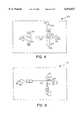
- FIG. 1provides a diagrammatic view of an enrichment channel for use in a device according to the subject invention.
- FIG. 2provides a diagrammatic view of an alternative embodiment of an enrichment channel also suitable for use in the subject device.
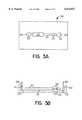
- FIG. 3Aprovides a top diagrammatic view of a device according to the subject invention.
- FIG. 3Bprovides a side view of the device of FIG. 3A.
- FIG. 4provides a diagrammatic top view of another embodiment of the subject invention.
- FIG. 5provides a diagrammatic view of an embodiment of the subject invention in which the enrichment channel comprises a single fluid inlet and outlet.
- FIG. 6provides a diagrammatic view of a device according to the subject invention in which the enrichment channel comprises an electrophoretic gel medium instead of the chromatographic material, as shown in FIGS. 1 and 2.
- FIG. 7provides a diagrammatic top view of disk shaped device according to the subject invention.
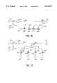
- FIG. 8is a flow diagram of a device as in FIGS. 1 or 2.
- FIG. 9is a flow diagram of a device as in FIGS. 3A, 3B.
- FIG. 10is a flow diagram of a device as in FIG. 4.
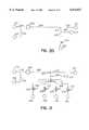
- FIG. 11is a flow diagram of a device as in FIG. 5.
- FIG. 12is a flow diagram of a device as in FIG. 6.
- FIG. 13is a flow diagram of a device as in FIG. 7.
- FIG. 14is a flow diagram of part of an embodiment of a device according to the invention, showing multiple inlets to the separation channel.
- FIG. 15is a flow diagram of an embodiment of a device according to the invention, showing an alternative configuration for the intersection between the main and secondary electrophoretic flowpaths.
- FIG. 16is a flow diagram of an embodiment of a device according to the invention, showing a plurality of analytical zones arranged in series downstream from the enrichment channel.
- FIG. 17is a flow diagram of an embodiment of a device according to the invention, showing a plurality of analytical zones arranged in parallel downstream from the enrichment channel.
- FIG. 18is a flow diagram of an embodiment of a device according to the invention, showing a plurality of main electrophoretic flowpaths downstream from the enrichment channel.
- FIG. 19is a flow diagram of an embodiment of a device according to the invention, showing a plurality of enrichment channels arranged in parallel.
- FIGS. 20 and 21are flow diagrams of embodiments of a device according to the invention, similar to those shown in FIGS. 15 and 16, respectively, and additionally having a reagent flowpath for carrying a reagent from a reservoir directly to the main electrophoretic flowpath.
- FIG. 22is a flow diagram of an embodiment of a device according to the invention, similar to that shown in FIG. 17, respectively, and additionally having a plurality of reagent flowpaths for carrying a reagent from a reservoir directly to downstream branches of the main electrophoretic flowpath.
- FIG. 23is a flow diagram of an embodiment of a device according to the invention, in which the enrichment medium includes coated magnetic beads.
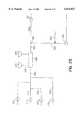
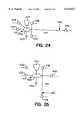
- FIGS. 24 and 25are flow diagrams showing embodiments of a device according to the invention, as may be used in the DNA capture method described in Example 7.
- FIG. 26is a reaction scheme showing synthesis of the 5-dethiobiotin-primer construct as described in Example 7.
- FIG. 27is a flow diagram of an embodiment of a device according to the invention, as may be used to separate a mixture of biological entities into four different subsets, by way of affinity-binding capture and release in affinity zones arranged in parallel.
- Integrated electrophoretic microdevicescomprising at least an enrichment channel and a main electrophoretic flowpath are provided.
- the enrichment channelserves to enrich a particular analyte comprising fraction of a liquid sample.
- the enrichment channel and main electrophoretic flowpathare positioned in the device so that waste fluid from the enrichment channel does not flow through the main electrophoretic channel, but instead flows away from the main electrophoretic flowpath through a discharge outlet.
- the subject devicesmay be used in a variety of electrophoretic applications, including clinical assay applications. In further describing the invention, the devices will first be described in general terms followed by a discussion of representative specific embodiments of the subject devices with reference to the figures.
- the subject deviceis an integrated electrophoretic microdevice.
- integratedis meant that all of the components of the device, e.g., the enrichment channel, the main electrophoretic flowpath, etc., are present in a single, compact, readily handled unit, such as a chip, disk or the like.
- the devicesare electrophoretic, they are useful in a wide variety of the applications in which entities, such as molecules, particles, cells and the like are moved through a medium under the influence of an applied electric field.
- the entitiesmay be moved through the medium under the direct influence of the applied electric field or as a result of bulk fluid flow through the pathway resulting from the application of the electric field, e.g., electroosmotic flow (EOF).
- EEFelectroosmotic flow
- the microdeviceswill comprise a microchannel as the main electrophoretic flowpath.
- microchannelBy microchannel is meant that the electrophoretic chamber of the main electrophoretic flowpath in which the medium is present is a conduit, e.g., trench or channel, having a cross sectional area which provides for capillary flow through the chamber, where the chamber is present on a planar substrate, as will be described below in greater detail.
- a conduite.g., trench or channel
- the deviceincludes an enrichment channel that includes a sample inlet and at least one fluid outlet, and contains an enrichment medium for enriching a particular fraction of a sample; optionally, the device further includes a second fluid outlet.
- the purpose of the enrichment channelis to process the initial sample to enrich for a particular fraction thereof, where the particular fraction being enriched includes the analyte or analytes of interest.
- the enrichment channelcan thus serve to selectively separate the fraction containing the target analyte from the remaining components of the initial sample volume.
- the target-containing fractionmay be retained within the enrichment channel, and the remainder flushed out from the channel for disposal or further treatment downstream; or, alternatively, selected components may be retained within the enrichment channel, and the target-containing fraction may be permitted to pass downstream for further processing.
- the enrichment channelcan provide for a number of different functions.
- the enrichment channelcan serve to place the analyte of interest into a smaller volume than the initial sample volume, i.e., it can serve as an analyte concentrator. Furthermore, it can serve to prevent potentially interfering sample components from entering and flowing through the main electrophoretic flowpath, i.e., it can serve as a sample "clean-up" means.
- the enrichment channelmay serve as a microreactor for preparative processes on target analyte present in a fluid sample, such as chemical, immunological, and enzymatic processes, e.g., labeling, protein digestion, DNA digestion or fragmentation, DNA synthesis, and the like.
- the enrichment channelmay be present in the device in a variety of configurations, depending on the particular enrichment medium housed therein.
- the internal volume of the channelwill usually range from about 1 pl to 1 ⁇ l, usually from about 1 pl to 100 nl, where the length of the channel will generally range from about 1 ⁇ m to 5 mm, usually 10 ⁇ m to 1 mm, and the cross-sectional dimensions (e.g., width, height) will range from about 1 ⁇ m to 200 ⁇ m, usually from about 10 ⁇ m to 100 ⁇ m.
- the cross-sectional shape of the channelmay be circular, ellipsoid, rectangular, trapezoidal, square, or other convenient configuration.
- enrichment mediamay be present in the enrichment channel.
- Representative enrichment medium or meansinclude those means described in the analyte preconcentration devices disclosed in U.S. Pat. No. 5,202,010; U.S. Pat. No. 5,246,577 and U.S. Pat. No. 5,340,452, as well as Tomlinson et al., supra, the disclosures of which are herein incorporated by reference.
- Specific enrichment means known in the art which may be adaptable for use in the subject integrated microchannel electrophoretic devicesinclude: those employed in protein preconcentration devices described in Kasicka & Prusik, "Isotachophoretic Electrodesorption of Proteins from an Affinity Adsorbent on a Microscale," J. Chromatogr.
- chromatographic media or materialsparticularly sorptive phase materials.
- Such materialsinclude: reverse phase materials, e.g., C8 or C18 compound coated particles; ion-exchange materials; affinity chromatographic materials in which a binding member is covalently bound to an insoluble matrix, where the binding member may group specific, e.g., a lectin, enzyme cofactor, Protein A and the like, or substance specific, e.g., antibody or binding fragment thereof, antigen for a particular antibody of interest, oligonucleotide and the like, where the insoluble matrix to which the binding member is bound may be particles, such as porous glass, polymeric beads, magnetic beads, networks of glass strands or filaments, a plurality of narrow rods or capillaries, the wall of the channel and the like.
- the enrichment meansis a chromatographic material
- typically samplewill be introduced into, and allowed to flow through, the enrichment channel. As the sample flows through the enrichment channel, the analyte comprising fraction will be retained in the enrichment channel by the chromatographic material and the remaining waste portion of the sample will flow out of the channel through the waste outlet.
- the beadsmay be coated with antibodies or other target-specific affinity binding moiety, including: affinity purified monoclonal antibodies to any of a variety of mammalian cell markers, particularly human cell markers, including markers for T cells, T cell subsets, B cells, monocytes, stem cells, myeloid cells, leukocytes, and HLA Class II positive cells; secondary antibodies to any of a variety of rodent cell markers, particularly mouse, rat or rabbit immunoglobulins, for isolation of B cells, T cells, and T cell subsets; uncoated or tosylactivated form for custom coating with any given biomolecule; and streptavidin-coated for use with biotinylated antibodies.
- Paramagnetic beads or particlesmay be retained in the enrichment channel by application of a magnetic field.
- solid phase materialssuch as coated particles or other insoluble matrices as the enrichment means
- a coated and/or impregnated membranewhich provides for selective retention of the analyte comprising fraction of the sample while allowing the remainder of the sample to flow through the membrane and out of the enrichment means through the waste outlet.
- hydrophilic, hydrophobic and ion-exchange membraneshave been developed for use in solid phase extraction which may find use in the subject invention. See, for example, Tomlinson et al, "Novel Modifications and Clinical Applications of Preconcentration-Capillary Electrophoresis-Mass Spectrometry," J. Cap. Elect.
- the enrichment channel or the enrichment mediumcan include a porous membrane or filter.
- Suitable materials for capturing genomic DNAs and viral nucleic acidsinclude those marketed by QIAGEN under the name QIAmp, for analysis of blood, tissues, and viral RNAs; and suitable materials for capturing DNAs from plant cells and tissues include those marketed by QIAGEN under the name DNeasy.
- the samplecan be caused to flow through the enrichment channel by any of a number of different means, and combinations of means. In some device configurations, it may be sufficient to allow the sample to flow through the device as a result of gravity forces on the sample; in some configurations, the device may be spun about a selected axis to impose a centrifugal force in a desired direction. In other embodiments, active pumping means may be employed to move sample through the enrichment channel and enrichment means housed therein. In other embodiments, magnetic forces may be applied to move the sample or to capture or immobilize a paramagnetic bead-target complex during wash and elution steps.
- electrodesmay be employed to apply an electric field which causes fluid to move through the enrichment channel.
- An elution liquidwill then be caused to flow through the enrichment medium to release the enriched sample fraction from the material and carry it to the main electrophoretic flowpath.
- an applied electric fieldwill be employed to move the elution liquid through the enrichment channel.
- Electrophoretic gel mediamay also be employed as enrichment means in the subject applications.
- Gel mediaproviding for a diversity of different sieving capabilities are known.
- the enrichment channelcomprises, in the direction of sample flow, a stacking gel of large porosity and a second gel of fine porosity, where the boundary between the gels occurs in the intersection of the enrichment channel and the main electrophoretic flowpath.
- the sample componentsmove through the stacking gel and condense into a narrow band at the gel interface in the intersection of the enrichment channel and main electrophoretic flowpath.
- a second electric fieldcan then be applied to the main electrophoretic flowpath so that the narrow band of the enriched sample fraction moves into and through the main electrophoretic flowpath.
- the enrichment channelcould comprise a gel of gradient porosity.
- the band(s) of interestwhen the band(s) of interest reaches the intersection of the enrichment channel and electrophoretic flowpath, the band(s) of interest can then be moved into and along the main electrophoretic flowpath.
- Enrichment mediathat can be particularly useful for enrichment and/or purification of nucleic acids include sequence specific capture media as well as generic capture media.
- Generic capture mediainclude, for example: ion exchange and silica resins or membranes which nonspecifically bind nucleic acids, and which can be expected to retain substantially all the DNA in a sample; immobilized single-stranded DNA binding protein (SSB Protein), which can be expected to bind substantially all single-stranded DNA in a sample; poly-dT modified beads, which can be expected to bind substantially all the mRNA in a sample.
- SSB Proteinimmobilized single-stranded DNA binding protein
- Sequence specific capture mediainclude beads, membranes or surfaces on which are immobilized any of a variety of capture molecules such as, for example: oligonucleotide probes, which can be expected to bind nucleic acids having complementary sequences in the sample; streptaviden, which can be expected to bind solution phase biotinylated probes which have hybridized with complementary sequences in the sample.
- Suitable beads for immobilization of capture moleculesinclude chemically or physically crosslinked gels and porous or non-porous resins such as polymeric or silica-based resins.
- Suitable capture media for proteinsinclude the following.
- Suitable capture media for proteinsinclude: ion exchange resins, including anion (e.g., DEAE) and cation exchange; hydrophobic interaction compounds (e.g., C4, C8 and C18 compounds); sulfhydryls; heparins; inherently active surfaces (e.g., plastics, nitrocellulose blotting papers); activated plastic surfaces; aromatic dyes such as Cibacron blue, Remazol orange, and Procion red.
- lectinsimmobilized hydrophobic octyl and phenylalkane derivatives can be suitable.
- analogs of a specific enzyme substrate-product transition-state intermediatecan be suitable; for kinases, calmodulin can be suitable.
- Suitable capture media for receptorsinclude receptor ligand affinity compounds.
- the enrichment channelwill comprise at least one inlet and at least one outlet.
- the inletmust serve to admit sample to the enrichment channel at an enrichment phase of the process, and to admit an elution medium during an elution phase of the process.
- the outletmust serve to discharge the portion of the sample that has been depleted of the fraction retained by the enrichment media, and to pass to the main electrophoretic microchannel the enriched fraction during the elution phase.
- the enrichment channelmay have more than one fluid inlet, serving as, e.g., sample inlet and elution buffer inlet; or the enrichment channel may have more than one outlet, serving as, e.g., waste outlet and enriched fraction fluid outlet.
- the enrichment channelis in direct fluid communication with the main electrophoretic channel, i.e., the enrichment channel and main electrophoretic flowpath are joined so that fluid flows from the enrichment channel immediately into the main electrophoretic flowpath, the enrichment channel will comprise, in addition to the waste outlet, an enriched fraction fluid outlet through which the enriched fraction of the sample flows into the main electrophoretic flowpath.
- one or more additional fluid inletsmay be provided to conduct such solvents into the enrichment channel from fluid reservoirs.
- fluid control meanse.g., valves, membranes, etc.
- electrodesmay be provided capable of applying an electric field to the material and fluid present in the enrichment channel.
- the next component of the subject devicesis the main electrophoretic flowpath.
- the main electrophoretic flowpathmay have a variety of configurations, including tube-like, trench-like or other convenient configuration, where the cross-sectional shape of the flowpath may be circular, ellipsoid, square, rectangular, triangular and the like so that it forms a microchannel on the surface of the planar substrate in which it is present.
- the microchannelwill have cross-sectional area which provides for capillary fluid flow through the microchannel, where at least one of the cross-sectional dimensions, e.g., width, height, diameter, will be at least about 1 ⁇ m, usually at least about 10 ⁇ m, but will not exceed about 200 ⁇ m, and will usually not exceed about 100 ⁇ m.
- the main electrophoretic flowpathmay be straight, curved or another convenient configuration on the surface of the planar substrate.
- the main electrophoretic flowpathwill have associated with it at least one pair of electrodes for applying an electric field to the medium present in the flowpath.
- a single pair of electrodestypically one member of the pair will be present at each end of the pathway.
- a plurality of electrodesmay be associated with the electrophoretic flowpath, as described in U.S. Pat. No. 5,126,022, the disclosure of which is herein incorporated by reference, where the plurality of electrodes can provide for precise movement of entities along the electrophoretic flowpath.
- the electrodes employed in the subject devicemay be any convenient type capable of applying an appropriate electric field to the medium present in the electrophoretic flowpath with which they are associated.
- the enrichment channel and the main electrophoretic flowpathare positioned in the device so that substantially only the enriched fraction of the sample flows through the main electrophoretic flowpath.
- the devicewill further comprise a discharge outlet for discharging a portion of sample other than the enriched fraction, e.g., the waste portion, away from the main electrophoretic flowpath.
- the enrichment channelis in direct fluid communication with the main electrophoretic flowpath
- the waste fluid flowpath through the enrichment channelwill be in an intersecting relationship with the main electrophoretic flowpath.
- the waste flowpath through the enrichment channeldoes not necessarily have to be in an intersecting relationship with the main electrophoretic flowpath; the waste flowpath and main electrophoretic flowpath could be parallel to one another.
- the subject deviceswill also comprise a means for transferring the enriched fraction from the enrichment channel to the main electrophoretic flowpath.
- the enriched fraction transfer meanscan be an enriched fraction fluid outlet, a secondary electrophoretic pathway, or other suitable transfer means.
- the second electrophoretic flowpathin addition to the main electrophoretic flowpath, the possibility exists to employ the second electrophoretic flowpath as a conduit for the enriched sample fraction from the enrichment channel to the main electrophoretic flowpath.
- the waste outletis the sole fluid outlet
- the presence of a secondary electrophoretic flowpathwill be essential, such that the enrichment channel and the main electrophoretic flowpath are in indirect fluid communication.
- the subject devicesmay further comprise one or more additional electrophoretic flowpaths, which may or may not be of capillary dimension and may serve a variety of purposes.
- additional electrophoretic flowpathsmay or may not be of capillary dimension and may serve a variety of purposes.
- devices comprising a plurality of electrophoretic flowpathsa variety of configurations are possible, such as a branched configuration in which a plurality of electrophoretic flowpaths are in fluid communication with the main electrophoretic flowpath. See U.S. Pat. No. 5,126,022, the disclosure of which is herein incorporated by reference.
- the main electrophoretic flowpath and/or any secondary electrophoretic flowpaths present in the devicemay optionally comprise, and usually will comprise, fluid reservoirs at one or both termini, i.e., either end, of the flowpaths.
- reservoirsmay serve a variety of purposes, such as a means for introducing buffer, elution solvent, reagent, rinse and wash solutions, and the like into the main electrophoretic flowpath, receiving waste fluid from the electrophoretic flowpath, and the like.
- a waste fluid reservoirfor receiving and storing the waste portion of the initial sample volume from the enrichment channel, where the waste reservoir will be in fluid communication with the discharge outlet.
- the discharge outletmay be the same as, or distinct from, the waste outlet, and may open into a waste reservoir or provide an outlet from the device.
- the waste reservoirmay be present in the device as a channel, compartment, or other convenient configuration which does not interfere with the other components of the device.
- the subject devicemay also optionally comprise an interface means for assisting in the introduction of sample into the sample preparation means.
- the devicemay comprise a syringe interface which serves as a guide for the syringe needle into the device, as a seal, and the like.
- At least in association with the main electrophoretic flowpathwill be a detection region for detecting the presence of a particular species in the medium contained in the electrophoretic flowpath.
- At least one region of the main electrophoretic flowpath in the detection regionwill be fabricated from a material that is optically transparent, generally allowing light of wavelengths ranging from 180 to 1500 nm, usually 220 to 800 nm, more usually 250 to 800 nm, to have low transmission losses. Suitable materials include fused silica, plastics, quartz glass, and the like.
- the integrated devicemay have any convenient configuration capable of comprising the enrichment channel and main electrophoretic flowpath, as well as any additional components. Because the devices are microchannel electrophoretic devices, the electrophoretic flowpaths will be present on the surface of a planar substrate, where the substrate will usually, though not necessarily, be covered with a planar cover plate to seal the microchannels present on the surface from the environment. Generally, the devices will be small, having a longest dimension in the surface plane of no more than about 200 mm, usually no more than about 100 mm so that the devices are readily handled and manipulated. As discussed above, the devices may have a variety of configurations, including parallelepiped, e.g., credit card or chip like, disk like, syringe like or any other compact, convenient configuration.
- parallelepipede.g., credit card or chip like, disk like, syringe like or any other compact, convenient configuration.
- the subject devicesmay be fabricated from a wide variety of materials, including glass, fused silica, acrylics, thermoplastics, and the like.
- the various components of the integrated devicemay be fabricated from the same or different materials, depending on the particular use of the device, the economic concerns, solvent compatibility, optical clarity, color, mechanical strength, and the like.
- both the planar substrate comprising the microchannel electrophoretic flowpaths and the cover platemay be fabricated from the same material, e.g., polymethylmethacrylate (PMMA), or different materials, e.g., a substrate of PMMA and a cover plate of glass.
- PMMApolymethylmethacrylate
- the devicewill typically be fabricated from a plastic.
- the entire devicemay be fabricated from a plastic material that is optically transparent, as that term is defined above.
- plastics having low surface charge under conditions of electrophoresisinclude polymethylmethacrylate, polycarbonate, polyethylene terepthalate, polystyrene or styrene copolymers, and the like.
- the devicesmay be fabricated using any convenient means, including conventional molding and casting techniques.
- a silica mold masterwhich is a negative for the channel structure in the planar substrate of the device can be prepared by etching or laser micromachining.
- the silica moldmay have a raised area which will provide for a cavity into the planar substrate for housing of the enrichment channel.
- a polymer precursor formulationcan be thermally cured or photopolymerized between the silica master and support planar plate, such as a glass plate.
- support planar platesuch as a glass plate.
- the enrichment channelmay be placed into the cavity in the planar substrate and electrodes introduced where desired.
- a cover platemay be placed over, and sealed to, the surface of the substrate, thereby forming an integrated device.
- the cover platemay be sealed to the substrate using any convenient means, including ultrasonic welding, adhesives, etc.
- Electrophoretic mediais used herein to refer to any medium to which an electric field is applied to move species through the medium.
- the electrophoretic mediacan be conveniently introduced through the reservoirs present at the termini of the electrophoretic flowpaths or directly into the channels or chambers of the electrophoretic flowpaths prior to sealing of the cover plate to the substrate. Any convenient electrophoretic medium may be employed.
- Electrophoretic media suitable for useinclude buffers, crosslinked and uncrosslinked polymeric media, organic solvents, detergents, and the like, as disclosed in Barron & Blanch, "DNA Separations by Slab Gel and Capillary Electrophoresis: Theory and Practice," Separation and Purification Methods (1995) 24:1-118, as well as in U.S. patent applications Ser. Nos. 08/636,599 and 08/589,150, and U.S. Pat. No. 5,569,314 the disclosures of which are herein incorporated by reference.
- electrophoretic mediaare cellulose derivatives, polyacrylamides, polyvinyl alcohols, polyethylene oxides, and the like.
- FIG. 1provides a diagrammatic view of an enrichment channel which may find use in the devices of the subject invention.
- Enrichment channel 10comprises side walls 1 which enclose reverse phase C18 material 2.
- Channel 10further comprise fluid inlets 7 and 4 and fluid outlets 5 and 6.
- valves 8, 9 and 11are provided for controlling fluid flow through the channel inlets and outlets.
- Glass frits 3allow for fluid flow through inlet 4 and outlet 5 but restrain reverse phase material 2 in the channel.
- sampleis introduced through sample inlet 7 in the direction of flowpath 12.
- the analyte comprising fractionis retained on reverse phase material 2 while the remaining waste fraction of the sample flows out waste outlet 6 along flowpath 13.
- Valves 8 and 9are closed to prevent sample from flowing or "bleeding" out inlet 4 or outlet 5. After the sample has flowed through channel 10, valve 11 is shut and valves 8 and 9 are opened. Elution buffer is then introduced into channel 10 through glass frit 3 and inlet 4 in the direction of flowpath 14. As elution buffer moves through material 2, the retained fraction of the sample is released and carried with the elution buffer out enriched fraction outlet 5 through frit 3 along flowpath 15.
- FIG. 2the same enrichment channel as shown in FIG. 1 is depicted with the exception that reverse phase material 2 is replaced by a network of crosslinked glass filaments 16 to which binding pair member is covalently bound.
- FIG. 3Aprovides a diagrammatic top view of a credit card shaped (parallelepiped) device according to the subject invention.
- Device 30comprises main electrophoretic flowpath 31 having reservoir 32 at a first end and reservoir 33 at a second end.
- enrichment channel 34In direct fluid communication with main electrophoretic flowpath 31 is enrichment channel 34 (seen from overhead). Electrodes 35 and 36 are provided for applying an electric field to the medium present in electrophoretic flowpath 31.
- Detection region 37is positioned over electrophoretic flowpath 31 for viewing analyte present in the medium comprised in the flowpath. A detection region can also be provided over the enrichment channel 34.
- the device shown in FIG. 3Acomprises a single enrichment channel, additional enrichment channels could be provided in the flowpath, including in the detection region.
- FIG. 3Bprovides a diagrammatic side view of the device depicted in FIG. 3A.
- sampleis introduced through syringe interface 38 into enrichment channel 34, where the analyte comprising fraction of the sample is retained as the waste fraction flows out of the enrichment channel 34 through discharge outlet 39 and out of the device.
- Elution bufferis then introduced into reservoir 32 through port 40.
- An electric fieldis then applied between electrodes 35 and 36 causing elution buffer to migrate from reservoir 32 through enrichment channel 34 and along electrophoretic flowpath 31 to reservoir 33.
- the elution buffermoves through enrichment channel 34, it releases the retained analyte comprising fraction of the initial sample volume and carries it into electrophoretic flowpath 31.
- FIG. 4shows a diagrammatic view of an embodiment of the subject invention in which the enrichment channel 62 is separated from main electrophoretic flowpath 52 by secondary electrophoretic flowpath 55.
- sampleis introduced into enrichment channel 62 through syringe interface 66.
- waste sampleflows through discharge outlet 64 into waste reservoir 63.
- An electric fieldis then applied between electrodes 61 and 60 causing elution buffer present in reservoir 57 to move through enrichment channel 62, resulting in the release of analyte.
- Analyteis then carried along secondary electrophoretic flowpath 55 along with the elution buffer.
- intersection 51When analyte reaches intersection 51, the electric field between electrodes 60 and 61 is replaced by an electric field between electrodes 59 and 58.
- the time at which analyte reaches intersection 51may be determined by detecting the presence of analyte in the intersection or by empirically determining the time at which the analyte should reach the intersection, based on the particular nature of the analyte, the medium in the flowpath, the strength of the electric field, and the like.
- the analytemoves from intersection 51 along electrophoretic flowpath 52 towards reservoir 53 and through detection region 65.
- FIG. 5provides a diagrammatic top view of yet another embodiment of the subject invention in which the enrichment channel comprises a single fluid inlet and outlet.
- Device 70comprises main electrophoretic flowpath 71 in intersecting relationship with secondary electrophoretic flowpath 73. Upstream from the intersection 82 along secondary electrophoretic flowpath 73 is enrichment channel 72.
- sampleis introduced through syringe interface 80 into enrichment channel 72, whereby the analyte comprising fraction of the sample is reversibly bound to the material present in the enrichment channel.
- An electric fieldis then applied between electrodes 81 and 79 which moves the non-reversibly bound or waste fraction of the sample out of the enrichment channel 72, along secondary electrophoretic flowpath 73, past intersection 82, and out discharge outlet 84 into waste reservoir 78.
- An elution bufferis then introduced into enrichment channel 72 through syringe interface 80 and an electric field applied between electrodes 81 and 79, causing elution buffer to flow through enrichment channel 72 into secondary flow electrophoretic flowpath 73, carrying analyte along with it.
- the device shown diagrammatically in FIG. 6comprises an enrichment channel having an electrophoretic enrichment means, instead of the chromatographic enrichment means of the devices of FIGS. 1 to 5.
- sampleis introduced into reservoir 96 and an electric field is applied between electrodes 87 and 88, causing the sample to migrate towards reservoir 98.
- the samplemigrates towards reservoir 98 it enters stacking gel 93 having a relatively large pore size and travels towards secondary gel 92 of relatively fine pore size.
- the sample componentsare compressed into a narrow band.
- the electric field between electrodes 87 and 88is replaced by an electric field between electrodes 89 and 90, which causes the narrow band of sample components at interface 93 to migrate into main electrophoretic flowpath 95, past detection region 91 and towards reservoir 85.
- device 90instead of the stacking gel configuration, one could provide for a molecular size membrane at the region of interface 93, which can provide for selective passage of sample components below a threshold mass and retention at the membrane surface of components in excess of the threshold mass.
- present at the location of interface 93could be an electrode by which an appropriate electric potential could be applied to maintain a sample component of interest in the region of 93, thereby providing for component concentration in the region of 93.
- an electric fieldcan then be applied between 89 and 90 causing the anionic analyte to migrate towards reservoir 85.
- FIG. 7provides a top diagrammatic view of a disk shaped embodiment of the subject device, as opposed to the credit card shaped embodiments of FIGS. 3 to 6.
- sampleis first introduced into enrichment channel 102.
- An electric fieldis then applied between electrodes 108 and 109, moving elution buffer 103 through enrichment channel 102, whereby analyte retained in the enrichment channel 102 is released and carried with the elution buffer to intersection 114.
- the electric field between 108 and 109is then replaced with an electric field between 110 and 111, causing analyte to move from intersection 114 along main electrophoretic flowpath 112, past detection region 113 and towards reservoir 107.
- FIGS. 8 through 19there is shown a flow diagram of an enrichment channel as shown in FIG. 1 or FIG. 2, with corresponding identification numbers.
- sampleenters enrichment channel 10 through sample inlet 7 by way of flowpath 12.
- an enrichment mediumwhich may be, for example, a reverse phase C18 material (as described with reference to FIG. 1) or binding pair members covalently bound to a network of glass filaments (as described with reference to FIG.
- FIG. 9there is shown a flow diagram of the embodiment of a device 30 as sketched in two views in FIGS. 3A, 3B and described with reference thereto.
- the enrichment channel(34 in FIGS. 3A, 3B, 9) is represented by a square;
- the various reservoirse.g., 32, 33 in FIGS. 3A, 3B, 9) are represented by small circles at the ends of the flowpaths (channels), which are represented by lines (e.g., main electrophoretic flowpath 31 in FIGS. 3A, 3B, 9); electrodes (35, 36 in FIGS.
- FIG. 12there is shown a flow diagram of the embodiment of a device 90 as sketched in FIG. 6 and described above with reference thereto.
- the enrichment channel (120 in FIG. 12)is shown in FIG. 12 and described above with reference thereto.
- the accumulation pointcan be an interface 94 between a stacking gel 93 and a secondary gel 92; and in a further modification, a suitable electrical potential can be applied at an electrode (121 in FIG. 12) at the site of the interface 93 to provide for component concentration in that region of the enrichment channel.
- FIG. 10is a flow diagram of the embodiment of a device 50 in which the enrichment channel 62 is separated from main electrophoretic flowpath 52 by secondary electrophoretic flowpath 55, as sketched in FIG. 4 and described above with reference thereto.
- FIG. 13is a flow diagram of the disc-shaped embodiment of a device 100 as sketched in FIG. 7 and described with reference thereto.
- FIG. 13shows the sample input flowpath by which the sample is introduced from the syringe interface 66 into the enrichment channel 102, and the discharge outlet 64 by which waste passes out to waste reservoir 63 while the fraction of interest is retained on the retention medium in the enrichment channel.
- FIG. 11there is shown a flow diagram of a device 70, in which there is only one fluid inlet into, and one fluid outlet out from, the enrichment channel 72, as sketched in FIG. 5 and described with reference thereto.
- the fluid inlet 116serves as a sample inlet
- the fluid outlet 118serves as a waste outlet.
- the waste fractionflows downstream through the secondary electrophoretic flowpath 73, across the intersection 82 of the secondary electrophoretic flowpath with the main electrophoretic flowpath 71, and into discharge outlet 84, which directs the waste away from the mail electrophoretic flowpath 71 toward waste reservoir 78.
- elution bufferis injected by way of the syringe interface; fluid inlet 116 serves as an elution buffer inlet and the fluid outlet 118 serves as an enriched fraction outlet to the secondary electrophoretic channel.
- the fraction of interestmoves into the elution buffer in which it is driven electrokinetically in an electric field produced by applying a voltage across electrodes 79, 81 to the intersection of the secondary electrophoretic channel and the main electrophoretic channel. Once the fraction of interest has reached the intersection, a voltage is applied across electrodes 76, 77 to draw the analyte or analytes in the fraction of interest into and along the main electrophoretic flowpath to the detection zone 99.
- the waste fraction(material not bound to the enrichment medium) can be washed out of the enrichment channel and away from the main electrophoretic pathway by application of an electric field between electrodes upstream from the enrichment channel and downstream from the discharge outlet. That is, prior to introducing the elution buffer to the enrichment channel, a liquid wash medium is passed over the enrichment medium and out through the discharge outlet, carrying away waste fraction components.
- a wash mediumAny of a variety of materials can be suitable as a wash medium, so long as the wash medium does not substantially elute the fraction of interest from the enrichment medium.
- the wash mediumcan be chosen to facilitate a selective release or removal, prior to elution, of undesired components that may be bound to or otherwise associated with the enrichment medium.
- the wash mediummay contain enzymes that selectively degrade proteins or polypeptides or that selectively degrade RNAs, facilitating the removal of these contaminants away from the fraction of interest prior to elution.
- the wash mediummay contain DNAses and RNAses.
- Sequential movement of the various liquids into and through the enrichment channelcan be readily controlled by providing a reservoir and a flowpath to the upstream part of the enrichment channel for each such liquid.
- an input 212 to enrichment channel 210is fed by a sample supply flowpath 220 running from a sample reservoir 218, by a wash medium flowpath 218 running from a wash medium reservoir 217, and by an elution medium flowpath 216 running from an elution medium reservoir 215. Movement of these materials can be selectively controlled by application of electrical potentials across electrodes (not shown the Fig.) at the respective reservoirs and at suitable points (as described herein for various configurations) downstream from enrichment channel output 214.
- Suitable wash media for proteinsinclude, for example, pH-adjusted buffers and organic solvents; and washing can be effected by, for example, adjusting ionic strength or temperature of the wash medium.
- a crude sample of body fluidblood, lymphatic fluid, amniotic fluid, cerebrospinal fluid, or urine, for example
- DNAmay be released from cells in a crude sample of whole blood by admixture of a reagent containing an enzyme or a detergent.
- the secondary electrophoretic flowpathdoes not cross the main electrophoretic flowpath; rather, main electrophoretic flowpath 238 joins secondary electrophoretic flowpath 236 at a T intersection (compare, FIG. 12).
- the upstream arm of the main electrophoretic flowpathruns in the same channel as the secondary electrophoretic flowpath 236.
- sampleenters the enrichment channel 230 by way of sample flowpath 234 from sample reservoir 233; and during the enrichment stage the waste fluid passes out from enrichment channel 230 by way of secondary electrophoretic flowpath 236, then past T intersection 237 and away through discharge outlet 240 to waste reservoir 241.
- a wash mediummay be passed through the enrichment channel and also out through the discharge outlet.
- the wash mediummay be introduced by way of the sample supply flowpath or, optionally, from a separate wash medium flowpath as described above with reference to FIG. 14.
- Movement of the sample and the wash mediumcan be accomplished by application of an electric field across electrodes (not shown in the Fig.) at waste reservoir 241 and, respectively, sample reservoir 233 (and, optionally, a wash reservoir). Then, an elution medium can be moved from an elution buffer reservoir 231 by way of elution buffer pathway 235 into and through enrichment channel 230, through secondary electrophoresis pathway 236. Media downstream from the eluting fraction components can be directed away from main electrophoretic flowpath 238 and out by way of waste discharge flowpath 240, until the most downstream component of interest has reached the intersection 237. Then an electrical potential can be applied at reservoir 239 to draw the components from secondary electrophoretic flowpath 236 through intersection 237 and within main electrophoretic flowpath 238 toward and through detection region 242.
- An intersection of the main and secondary electrophoretic flowpaths at an "injection cross", as shown for example in FIGS. 5, 12,can be advantageous where precise metering of the sample plug is desired, as for example, where the main electrophoretic flowpath is used for electrophoretic separation.
- Such an injection crosscan provide for injection from the intersection of a geometrically defined plug of sample components from the fraction of interest.
- a T intersectioncan be preferred.
- Such a configurationmay be advantageous where, for example, the components are analyzed by passing substantially the entire eluted fraction through an array of affinity zones downstream from the intersection.
- FIG. 16is a diagram showing the flow in a configuration having a serial array of affinity zones 244, 246, 248, 250.
- Each affinity zoneis provided with an enrichment medium that has a specific affinity for a selected component of the fraction of interest.
- the fraction of interestmay consist of DNA in a crude cell lysate, wherein the lysate may have been formed upstream from enrichment channel 230 and concentrated and/or purified in enrichment channel 230, so that the eluted fraction that passes into main electrophoretic flowpath 238 consists principally of a complex mixture of DNA fragments of different lengths and base composition.
- Each hybridization zoneis itself an enrichment channel, in which the enrichment medium includes an immobilized oligonucleotide probe having a sequence complementary to a sequence in a target DNA.
- the affinity zonesare provided with detectors 243, 245, 247, 249, configured to detect and, optionally, to quantify, a signal (such as fluorescence or electrochemilluminescence) from components of interest bound in the affinity zones. Any form of biomolecular recognition may be employed as a capture principle in the affinity zones, as the skilled artisan will appreciate.
- affinityinclude antibody-antigen interactions; binding of poly-dT with adenylated RNA; oligonucleotide probes for RNA, DNA, PNA; streptavidin-biotin binding; protein-DNA interactions, such as DNA-binding protein G or protein A; and molecules having group specific affinities, such as arginine, benzamidine, heparin, and lectins.
- group specific affinitiessuch as arginine, benzamidine, heparin, and lectins.
- the capture principlemay include receptor-ligand binding, antibody-antigen binding, etc.
- the methods and devices according to the inventioncan be useful for carrying out immunoassays, receptor binding assays, and the like, as well as for nucleic acid hybridization assays.
- the main electrophoretic flowpathcan be branched downstream from the intersection with the secondary electrophoretic flowpath, providing a parallel array of main electrophoretic flowpaths, as shown by way of example in FIG. 17.
- Electrophoretic flowpath 238is shown as twice bifurcated, so that four main electrophoretic flowpath branches run downstream to their respective waste reservoirs 262, 264, 266, 268.
- the branchesare provided in this example with affinity zones 254, 256, 258, 260, with detectors 253, 255, 257, 259.
- Pertinent properties of the milieu(such as, e.g., temperature, pH, buffer conditions, and the like) can advantageously be controlled in each flowpath branch independently of the others, as is shown in more detail with reference to FIG. 22, below.
- each affinity zonereceives an aliquot of the entire sample that is delivered to the main electrophoresis channel.
- sample components that can be captured by two or more of the affinity mediawill appear in the respective two or more affinity zones.
- a nucleic acid fragment that contains either one or both of two sequences complementary to two of the probe sequenceswill, in the parallel arrangement, be captured in the two affinity zones containing those two probes.
- each downstream affinity zoneis reached only by sample components not captured by an affinity zone upstream from it.
- nucleic acid fragment that contains both of two sequences complementary to probe sequences in two of the affinity zoneswill be captured only in the more upstream of the two affinity zones. This arrangement may be advantageous where it is desirable to identify sample components that contain one but not another moiety or sequence.
- a plurality of main electrophoretic flowpathsmay be provided for treatment of the enriched eluted sample.
- the main electrophoretic flowpaths 270may carry eluted sample fraction from the secondary electrophoretic flowpath 236 through a series of intersections 272.
- Each main electrophoretic flowpath 270is provided with reservoirs upstream (274) and downstream (276) and each is provided with a detector 278. This configuration may be employed to run a set of tests or assays or measurements on aliquots of a single enriched sample fraction, and will be particularly useful where, as noted above, precise metering of the quantity of analyte is desirable.
- each of the main electrophoretic flowpaths 270can be provided with an affinity zone or with an array of affinity zones (not shown in FIG. 18) as described above with reference to FIGS. 16, 17.
- a plurality of enrichment channels 280can receive sample from a branched sample supply manifold 281.
- Each enrichment channel 280can during the elution stage deliver an enriched fraction to an intersection 288 with a main electrophoretic flowpath 284.
- waste fractionis carried away from the intersections 288 by way of a branched discharge manifold 283 and out through discharge outlet 240 to waste 241.
- Such an arrangementcan be used to particular advantage, for example, where the fraction of interest is a mixture of DNAs, and where it is desirable to obtain both sequence information and size information for the DNAs.
- 19can be used, for example, for a flow-through analysis analogous to a Southern blot analysis.
- a flow-through analysisanalogous to a Southern blot analysis.
- DNA fragmentsare first separated on a gel, and then transferred to a membrane on which probes are allowed to bind complementary fragments.
- the Southern blot analysisis practiced mainly as a manual bench-top procedure, and is highly labor-intensive, taking several days to complete.
- the flow-through analysis, according to the inventioncan be substantially automated, and the analysis can be completed much more rapidly.
- each but one of the enrichment channelsis provided with a sequence-specific capture medium, such as a sequence-specific immobilized oligonucleotide probe, and the last one of the enrichment channels is provided with a generic capture medium which binds all DNA fragments in the sample.
- sequence-specific capture mediumsuch as a sequence-specific immobilized oligonucleotide probe
- generic capture mediumwhich binds all DNA fragments in the sample.
- affinity binding agents on particulate supportscan, in certain configurations of flowpaths, provide for highly efficient separation of a selected subset of biological entities from among two or more subsets in a mixed population of biological entities, where each subset has a characteristic determinant.
- several enrichment channels, or affinity zones, in each of which is held a capture agent capable of selectively binding a determinant on a subset of biological entitiescan be arranged in parallel.
- the capture agentsinclude a first capture agent comprising a receptor which specifically binds, either directly or indirectly, to the characteristic determinant of the first subset, and at least a second capture agent comprising a receptor which specifically binds, either directly or indirectly, to the characteristic determinant of at least one other subset.
- the subset to which each capture agent bindsis the target subset of each capture agent.
- a sample of the mixed population of biological entitiesis contacted with the plurality of capture agents, under conditions favoring specific binding of the receptor of the first capture agent to the first subset, and of the receptor of the second capture agent to at least one other subset, where at least one of the capture agents is dissociably bound to its respective subset.
- the bound subsetsare next separated from the sample and from any subset of the population of biological entities that is not bound to a capture agent.
- One of the dissociably bound subsetsis thereafter dissociated from the capture agent to which it is bound, and is thereafter isolated.
- the isolated, selected subsetis normally recovered for further processing, which may include analysis and/or propagation.
- dissociation and isolation steps as described abovemay be repeated to yield a second or third selected subset, and so on, if desired, provided that dissociation of the one capture agent from its target subset does not result in dissociation of another capture agent from its selected target subset.
- operating parameters and device configurationenable successful performance of biological and other separations not heretofore attainable.
- capture and separation of the target substanceare simultaneous events.
- these two eventsare separate. The bifurcation of these two events according to a preferred embodiment of this invention affords significant advantages.
- affinity-binding reactionsare coupled with respective specific cleavage reaction.
- affinity-binding/cleavage pairstwo distinct specificities for each separation procedure result.
- a multiple parallel microchannel configurationprovides for highly efficient separations.
- the second wayinvolves the high degree of control that is afforded over the collection of the biological entities, such that after an individual affinity bond between the biological entity and the solid support is cleaved, which may be either before or after resuspension of the collected biological entities, a second collection of the particles results in segregation of the original mixed population with the exception of the subset of biological entities that was bound by the specific receptor which was selectively released from its target subset via bond cleavage.
- the present inventionis not limited to the selected control and manipulation of the physiochemical environment associated with bond breaking and deposition of the captured biological substances. Instead, a multiplexed microfluidic configuration provides enormous flexibility in the design of integrated devices for the separation of mixtures of biological components. Thus, a combination of both approaches may be utilized in cases when multiple subsets of biological entities are to be isolated from a mixed cell population which vary greatly in frequencies.
- FIG. 27showing a configuration of flow paths in a microfluidic device according to the invention that can be used for separation of a mixture of five different biological entities (here, different cell types presenting as determinants different cell surface receptors) into four separate subsets.
- biological entityrefers to a wide variety of substance of biological origin including cells, and cell components such as membranes, organelles, etc., microbes, viruses, as well as molecules (e.g., proteins) and macromolecules (e.g., nucleic acids, including RNAs, DNAs and PNAs).
- the biological entities of interestmay be present in test samples or specimens of a wide range of origins, including for example biological fluids or extracts, food samples, environmental samples, etc.
- determinantis used here in a broad sense to denote any characteristic that identifies or determines the nature of of an entity. When used in reference to any of the above-described biological entities, determinant means that portion of the biological entity involved in and responsible for selective binding to a specific binding substance, the presence of which is required for selective binding to occur.
- binding substancerefers to any substance that selectively recognizes and interacts with the characteristic determinant on a biological entity of interest, to the substantial exclusion of determinants present on biological entities that are not of interest.
- the capture agents used in the affinity binding separationsinclude a specific binding agent, or receptor, attached to a solid support.
- the solid supportmay be either stationary or mobile.
- Useful mobile solid phasesinclude, for example, beads and particles.
- Particulate solid supportsare preferably made from magnetic material to facilitate capture of the target subsets by application of a magnetic field.
- a heterogeneous mixture of biological entitiesis separated into sub-populations as characterized by the determinants of the constituents of the sample.
- the methodis simple, rapid and reliable.
- Antibodies specific to corresponding cell surface antigensserve as capture reagents for isolating the specific targets from complex mixtures.
- the mixed population of biological entitiesmay also include, but is not limited to, whole cells presenting cell surface receptors, cell membranes bearing cell surface receptors, soluble receptors, enzymes, antibodies, and specific nucleic acid sequences.
- the integrated device as shown in FIG. 27includes duplicate flow patterns configured in four parallel networks of microchannels (denoted A, B, C, and D) for illustration purposes.
- a highly multiplexed configurationcomprising of many parallel networks (more than four) is, as will be appreciated, contemplated within the invention.
- each microfluidic networkincludes a capture channel (or "enrichment zone"), having specific capture reagents (in this case, immobilized antibodies), in fluid communication with two inlet and two outlet flowpaths.
- capture channelor "enrichment zone”
- specific capture reagentsin this case, immobilized antibodies
- sample inlet reservoir 502which serves as the common inlet for the entire device, and microchannels 504, 506, and 511.
- the other inlet flowpath, specific to network A,comprises elution buffer reservoir 501 and microchannel 521.
- One outlet flowpathcomprises the common outlet reservoir 592 and microchannels 561, 594 and 596.
- the other outlet flowpathcomprises of the analysis channel 551, outlet reservoir 591 and the detection zone 581.
- the three stage cell isolation processis initiated by injecting a complex mixture of biological cells into the multiplexed flow pattern as schematically illustrated in FIG. 27.
- Sample handling on the microfluidic deviceis achieved electrokinetically by controlling the electric potential across the appropriate electrodes (not shown in FIG. 27) placed within the inlet and outlet reservoirs.
- cellsare captured by means of antibodies immobilized to the surface of the channels that recognize specific cell surface antigens.
- immunomagnetic beadsmay be employed for cell capture.
- the heterogeneous suspension of cellsbind the target (e.g., antibodies to cell surface antigens) by specific absorption to the particular capture moieties on the surface of the beads. Immobilization of the target-bead complex to the side of enrichment chambers can then be achieved magnetically.
- a mixture of, e.g., six different cell typescan be separated into four distinct subsets when bound to capture agents including four antibodies having different binding specificities.
- antibodies to cell surface antigens denoted by A, B, C, and Dare immobilized in channels 541, 543, 545, and 547, respectively.
- each of the enrichment channels 541, 543, 545, and 547has associated with it a corresponding set of intersecting inlet and outlet flowpaths and reservoirs, analysis channels and detection zones.
- cells denoted A, B, C, and D arising from their respective surface antigensare captured in the above-referenced channels within the microfluidic networks A, B, C and D.
- the remaining cellsare passed through the device and collected in the common outlet reservoir 592. The remaining cells may then be used in various applications as described further below.
- a wash medium contained within wash buffer reservoirsmay be used to rinse the immobilized cells.
- the isolated cells captured in their respective enrichment zonescan next be released and then analyzed within the detection zones 581, 583, 585, and 587 by electrokinetically pumping elution buffer from reservoirs 501, 503, 505, and 507 to the outlet reservoirs 591, 593, 595, and 597, respectively.
- the detection zonesmay simply be an optical detector, e.g., fluorescence detector or the like, or it may represent a further flow configuration.
- a single heterogeneous enrichment zonemay alternatively be employed with a plurality of receptors (e.g., in this case, antibodies specific to the cell surface antigens) immobilized to the affinity channel.
- receptorse.g., in this case, antibodies specific to the cell surface antigens
- Heterogeneous capture and release methodsare described in, e.g., U.S. Pat. No. 5,646,001 to Terstappen et al., which is incorporated herein by reference in its entirety.
- an advantage of the parallel approachis that separate homogeneous capture zones minimize the physical impact on the biological entities.
- an affinity-capture method utilizing a single enrichment column with a plurality of receptorsis possible only provided that the bond linking one capture agent to a selected target subset is differentially dissociable from the bond linking the other capture agents to their respective, selected target subsets, such that dissociation of the one capture agent from its target subset will not result in dissociation of another capture agent from its selected target subset.
- a further significant advantage of the microfluidic devices and methods of the present inventionincludes the integrated systems capabilities which enable multiplexed cellular analyses to be performed on-line with the cell purification process.
- a portable self-contained microfluidics cartridge similar to that illustrated schematically in FIG. 27may be employed in parallel with a conventional high gradient magnetic separation (HGMS) device, as discussed below, for the rapid, quantitative and simultaneous measurement of a panel of tests to aid in the diagnosis and treatment of human disease.
- HGMShigh gradient magnetic separation
- a microfluidics based method and apparatuscomprising a massively parallel channel configuration provides for economical, high throughput cell purification combined with integrated cellular diagnostics.
- this automated processis not laborious and time consuming as are conventional cell isolation methods.
- the present inventionalso broadly encompasses methods of using integrated microfluidic devices to deplete selected cells from a sample.
- High gradient magnetic separationhas been used for the removal of magnetically labeled cells from suspensions of bone marrow, peripheral and/or cord blood cells. See, U.S. Pat. Nos. 5,514,340 and 5,691,208, which are incorporated herein by reference in their entireties.
- HGMS methodstypically involve placing a filter of fine magnetizable wires in a strong magnetic field. High gradient magnetic fields are produced around the wires, allowing the capture of even very weakly magnetic particles upon the magnetizable wires.
- the present inventioncontemplates a microfluidic-based cell purification or cell purging apparatus and method for recovering hematopoietic stem/progenitor cells from bone marrow, peripheral and cord blood and/or hematopoietic tissue for transplantation.
- Existing HGMS methodscommonly employ a three stage process to achieve cell selection. Magnetically conjugated antibodies are used to specifically target the desired cells in a mixed population of cells. The noncaptured cells that have been treated in the purification process can then be used for numerous purposes, including, e.g., bone marrow/stem cell transplantation.
- the integrated chip-based cell-sorting device and methodincludes: 1) the flow-through incubation of selected cells and antibodies specific to cell surface antigens; 2) the addition of surface-activated magnetic beads which bind with the antibodies followed by another flow-through incubation step; 3) application of a magnetic field for the affinity capture of the bead-antibody-cell complex; and 4) the magnetic release of the complex or the chemical elution/thermal dissociation of the antibody-cell surface antigen bond.
- the devicemay be employed not only to deplete but also to further analyze the unwanted "selected" cells (e.g., T cells, tumor cells or oncotopes) from a mixed population.
- Analysesmay include, but are not limited to, cell counting, cell staining, cell sorting, cell lysis, genetic testing, competitive binding and/or "sandwich” assays employing fluorescent or other like means for detection. These assays have applications in immunodiagnostics, characterizing receptor-ligand affinity interactions and DNA hybridization reactions.
- the inventionprovides means for the automated electroactive control of the fluid circuitry without requiring the use of mechanical valves, as described in U.S. Pat. No. 5,691,208.
- Electrokinetic pumping methods and devicesare described in, e.g., U.S. Ser. No. 08/615,642, filed Mar. 13, 1996 (Attorney Docket No. A-63053-4) the disclosure of which is hereby incorporated herein by reference in its entirety.
- Monoclonal antibodies that recognize a stage-specific antigen or immature human marrow cells and/or pluripotent lymphohematopoietic stem cellsmay be employed as described in, e.g., U.S. Pat. No. 4,714,680, which is incorporated herein by reference in its entirety.
- affinity capture and releasecan be effected, where one of the downstream reservoirs collects the purified or processed sample mixture.
- additional input reservoirs upstream from the enrichment channel or affinity zonecan be provided, as shown for example in FIG. 14.
- the device of the inventionmay be used to deplete selected cells from a sample, such as cells which express cell surface antigens recognized by antibodies, preferably monoclonal antibodies.
- the methodis used to deplete selected cells from cell suspensions obtained from blood and bone marrow.
- the methodmay be used to deplete tumor cells from bone marrow or blood samples harvested for autologous transplantation, or deplete T lymphocytes from bone marrow or blood samples harvested for allogeneic transplantation.
- the device of the inventionmay also be used to remove virus particles from a sample.
- the device and methods of the inventionmay be used in the processing of biological samples including bone marrow, cord blood and whole blood.
- the device and methods of the inventionare preferably used to deplete or purge tumor cells or T lymphocytes from samples to prepare hematopoietic cell preparations for use in transplantation as well as other therapeutic methods that are readily apparent to those of skill in the art.
- bone marrowcan be harvested from a patient suffering from lymphoma or other malignancies, the sample may be substantially depleted of any tumor cells using the device and methods described herein, and the resulting hematopoietic cell preparation may be used in therapeutic methods.
- Bone marrow or bloodcan also be harvested from a donor in the case of an allogenic transplant and depleted of T lymphocytes by the methods described herein.
- hematopoietic cell populationcontaining greater than 50% of the hematopoietic cells present in the original sample, and which is depleted of T lymphocytes or tumor cells in the original sample by greater than 2 logarithms may be obtained.
- the hematopoietic cells in the preparationare not coated with antibodies or modified making them highly suitable for transplantation and other therapeutic uses that are readily apparent to those of skill in the art.
- the method and device of the inventionmay also be used to remove red blood cells from samples such as blood and bone marrow.
- Half of the volume of normal bloodconsists of mature red blood cells. Typically these cells exceed nucleated cells by >100 fold.
- removal of red blood cells with higher recovery of cells than conventional methodssuch as Ficoll-Hypaque density centrifugation.
- samplesmay be processed using the methods and device described herein for diagnostic flow cytometry of leukocyte subpopulations.
- the methodsmay be used to prepare blood samples of patients infected with the Human Immuno Deficiency (HIV) virus for monitoring lymphocyte populations in such patients.
- HIVHuman Immuno Deficiency
- Enumeration of the absolute numbers of leukocyte subpopulation by conventional immunofluorescence measurements and flow cytometryhas been complicated by the abundant presence of red blood cells in peripheral blood and consequently, such enumeration is most often derived from separate measurements of nucleated cells numbers and immunophenotype.
- the present inventionprovides an efficient and direct method for removing red blood cells from blood samples that can readily be automated as no centrifugation or wash steps are involved.
- Examples of uses to which the invention may be putinclude: Depletion of CD3+T cells from allogeneic bone marrow using the device of the invention for the prevention of graft versus host disease (GVHD); Isolation of hematopoietic progenitor cells and depletion of malignant cells in patients with B-lymphoid malignancies; Removal of CD45RA+lymphoma cells from bone marrow; Purging of breast cancer cells from peripheral blood and bone marrow; Purification of CD34+cells by immunomagnetic removal of CD34-cells; Depletion of murine cells that express lineage markers; Immunomagnetic removal of red blood cells; Cellular diagnostics--employing a microfluidic-based panel of tests; Isolation of fetal nucleated erythrocytes from maternal blood; Isolation of genetically modified hematopoietic stem cells and depletion of malignant cells of non-hematopoietic origin--as for gene therapy, for instance; I
- FIG. 20is a flow diagram similar to one shown in FIG. 15.
- a reagent flowpath 300carries a reagent (or reagents) ftom a reservoir 301 to the main electrophoretic flowpath 238, where the reagent can combine with and react with one or more analytes in the enriched fraction.
- each such downstream branchcan be provided with a reagent flowpath carrying reagent from a reservoir.
- Such a configurationcan provide either for replicate treatment of the subfractions with a single reagent, or for treatment of each subfraction with a different reagent, or for simultaneous treatment of subfractions with two or more reagents, each producing a particular desired result upon interaction with the analyte(s) in the enriched subfraction.
- FIGS. 21 and 22are flow diagrams similar to those shown in FIGS. 16 and 17, having multiple branched main electrophoretic flowpaths, each branch provided with an affinity zone.
- reagent flowpath 300carries a reagent (or reagents) from a reservoir 301 to the main electrophoretic flowpath 238, where the reagent can combine with and react with one or more analytes in the enriched fraction.
- the reagent supplied by reservoir 301effects a replicate treatment of all the subfractions that are treated on the downstream branches and detected in the respective affinity zones.
- each of the downstream branches of the main electrophoretic flowpath 238is provided with reagent flowpath (302, 304, 306, 308) each carrying a reagent from a separate reagent reservoir (303, 305, 307, 309).
- reagent flowpath(302, 304, 306, 308) each carrying a reagent from a separate reagent reservoir (303, 305, 307, 309).
- devices providing flowpaths as in any of FIGS. 18 through 22, or a combination of thesecan be used for DNA profiling. More specifically, for example, restriction fragment polymorphism ("RFLP") analysis can be carried out by employing a plurality of different single-locus RFLP probes in reservoirs 303, 305, 307 and 309 as shown in FIG. 22. By running a large number of probes in parallel, the resulting distribution of alleles should yield a rapid and representative DNA profile, while significantly minimizing the possibility of random matches.
- RFLPrestriction fragment polymorphism
- the subject devicesmay be used in a variety of applications, where one or more electric fields are applied to a medium to move entities through the medium.
- Representative applicationsinclude electrophoretic separation applications, nucleic acid hybridization, ligand binding, preparation applications, sequencing applications, synthesis applications, analyte identification applications, including clinical, environmental, quality control applications, and the like.
- representative samplesinclude bodily fluids, environmental fluid samples, e.g., water and the like, or other fluid samples in which the identification and/or isolation of a particular analyte is desired.
- analytesmay be of interest, including drugs, toxins, naturally occurring compounds such as peptides and nucleic acids, proteins, glycoproteins, organic and inorganic ions, steroids, and the like.
- drugsdrugs, toxins, naturally occurring compounds such as peptides and nucleic acids, proteins, glycoproteins, organic and inorganic ions, steroids, and the like.
- samples that may be analyzedinclude blood, urine, plasma, cerebrospinal fluid, tears, nasal or ear discharge, tissue lysate, saliva, ocular scratches, fine needle biopsies, and the like, where the sample may or may not need to be retreated, i.e., combined with a solvent to decrease viscosity, decrease ionic strength, or increase solubility or buffer to a specific pH, and the like, prior to introduction into the device.
- analytes of interestinclude anions, cations, small organic molecules including metabolites of drugs or xenobiotics, peptides, proteins, glycoproteins, oligosaccharides, oligonucleotides, DNA, RNA, lipids, steroids, cholesterols, and the like.
- a card as shown in FIG. 4is used in the separation of organic analytes in an aqueous sample as follows in conjunction with a device that provides for the application of appropriate electric fields through introduction of electrodes into each reservoir of the card and provides for a means of detecting analyte as it passes through detection region 65.
- the enrichment channel 62comprises porous beads coated with a C-18 phase, while the reservoirs and channels, except for the waste reservoir, comprise 20 millimolar borate buffer.
- a 100 ⁇ l aqueous sampleis injected into enrichment channel 62 through interface 66.
- Substantially all of the organic analyte in the samplereversibly binds to the C18 coated porous beads, while the remaining sample components flow out of enrichment channel 62 into waste reservoir 63.
- 10 ⁇ l of an elution buffer(90% methanol/ 10% 20 millimolar borate buffer pH 8.3) are then introduced into the enrichment channel 62 through interface 66, whereby the reversibly bound organic analyte becomes free in the elution buffer. Because of the small volume of elution buffer employed, the concentration of analyte in the volume of elution buffer as compared to the analyte concentration in the original sample is increased 100 to 1000 times.
- the seals over reservoirs 57 and 56are then removed and an electric field is applied between electrodes 61 and 60, causing buffer present in 57 to move towards 56, where movement of the buffer front moves the elution plug comprising the concentrated analyte to intersection 51.
- a voltage gradientis then applied between electrodes 58 and 59, causing the narrow band of analyte present in the volume of elution buffer to move through separation channel 52, yielding high efficiency separation of the organic analytes.
- the devicein addition to reservoir 57, the device comprises an elution buffer reservoir also in fluid communication with the enrichment channel 62.
- sampleis introduced into enrichment channel 62, whereby the organic analytes present in the elution buffer reversibly bind to the C18 phase coated beads present in the enrichment channel.
- An electric fieldis applied between an electrode present in the elution buffer reservoir and electrode 60 for a limited period of time sufficient to cause 10 ⁇ l of elution buffer to migrate through the enrichment channel and release any reversibly bound organic analyte.
- a voltage gradientis then applied between electrodes 61 and 60, resulting in the movement of buffer from 57 to 56, which carries the defined volume of organic analyte comprising elution buffer to intersection 51, as described above.
- a crude sample composed of a particular targetis treated using magnetic beads, coated with an affinity medium, to capture a target having a binding affinity for the specific affinity medium.
- magnetic beadsare marketed, for example, by Dynal, Inc. New York, under the name Dynabeads®.
- Dynabeadsare superparamagnetic, monodispersed polystyrene microspheres coated with antibodies or other binding moieties that selectively bind to a target, which may be or include cells, genes, bacteria, or other biomolecules.
- the target-Dynabead complexis then isolated using a magnet.
- the resulting biomagnetic separation procedureis simple, rapid and reliable, whereby the Dynabeads serve as a generic enrichment medium for isolating specific targets from complex heterogeneous biological mixtures.
- Such magnetic enrichment mediamay be employed according to the invention in a wide variety of applications involving cell biology, molecular biology, HLA tissue typing, and microbiology, for example. Two illustrative examples are provided here, specifically, methods for DNA purification and cell isolation.
- microchannel-based deviceis generally described, and then the method of employing Dynal beads for biomagnetic separation is generally described.
- the integrated microfluidic deviceincludes a main electrophoretic flowpath 394 coupled to an enrichment channel, 382 which includes a solid phase extraction (SPE) chamber 380, and which is connected to downstream waste reservoir 391.
- the main electrophoretic flowpathwhich consists of an enriched-sample detection region 393 and fluid outlet reservoir 395, joins the secondary electrophoretic flowpath 384 at a T intersection 388.
- sample handlingis achieved electrokinetically by controlling the electric potential across the appropriate electrodes placed within the inlet reservoirs for the wash 373 and elution 375 buffers and outlet reservoirs 391 and 395.
- the Dynabeads and then the sample of interestare introduced into the device through injection inlet ports 379 and 377, respectively.
- the heterogeneous suspension of sample and Dynabeads specific for a given targetincubate allowing the Dynabeads to bind the target by specific absorption to the particular capture moieties on the surface of the beads.
- Immobilization of the target-bead complex to the side of enrichment chamber 380is achieved magnetically. This is possible manually by placing a rare earth permanent magnet adjacent to the enrichment chamber.
- an automated protocolemploying electromagnetic means is used to control the applied magnetic field imposed on the SPE chamber.
- a wash medium contained within wash buffer reservoir 373can be moved via pathway 374 into and through enrichment channel 380.
- the waste fluidpasses out from the enrichment chamber 380 by way of the electrophoretic flow path 384, then past the T intersection 388 and away through the discharge outlet 392 to waste reservoir 391.
- the supernatant from the wash stepsis removed from the system without having to pass the waste through the main electrophoretic channel 394.
- An experimental method employing an electrophoretic microdevice as schematically represented in FIG. 23is provided in which Dynal® biomagnetic beads are used as an enrichment medium for extracting and purifying genomic DNA from whole blood.
- the source of bloodmay be a small dried forensic sample on a slide (e.g., on the order of a nanogram), an aliquot of freshly drawn arterial blood (as small as 10 ⁇ l) or bone marrow (approximately 5 ⁇ l).
- a protocol amenable to rapid DNA isolation and elutionwill be provided for the purpose of demonstrating an automated procedure for treating whole blood on-board the device of FIG. 23 so as to yield aliquots of DNA for amplification and analysis or for direct analysis without amplification.
- the processincludes the following steps:
- loading of the biomagnetic separation media, lysis solution and sampleis achieved by means of specially designed injection ports to accommodate differences in the reagents and sample.
- the Dynal DIRECTTM reagentswhich include the lysis solution and magnetic beads, are first injected directly into the solid phase extraction chamber 380 via manual injection port 379, followed by manual injection of the blood sample into the SPE chamber via the injection port 377.
- other commercial reagentsmay be used where the nuclei lysis solution and beads are not packaged together as a kit but are instead supplied separately.
- a lysis solutioncan be electrokinetically loaded into the SPE chamber 380 from the inlet reservoir 371.
- Magnetic beadssupplied for example by Japan Synthetic Rubber, are next loaded either from the injection port 379 or electrokinetically from inlet reservoir 369.
- the beadsare confined to the chamber by electromagnetic capture, mechanical means (e.g., membrane, mesh screen, or agarose gel plug) placed just downstream of the SPE chamber in flowpath 384, or both.
- mechanical meanse.g., membrane, mesh screen, or agarose gel plug
- the blood sample, lysis solution and Dynabeadsare allowed to incubate for five minutes during which the cells are lysed. Released nucleic acids can then absorb to the capture moieties immobilized on the surface of the microparticles to form a DNA-bead complex.
- mixingcan be achieved by, for example, arranging the supply channels so that the streams of beads, sample, and lysis solution merge. Mixing can be enhanced electrokinetically by judicious control of the applied electric field. By periodically reversing the polarity of the electrodes placed in the inlet and outlet reservoirs 371 and 391, respectively, it is possible to electrokinetically move the blood-lysis buffer mixture in an oscillatory manner within the SPE chamber.
- aperture-like structurescan be molded into the SPE chamber housing.
- rinsingis achieved by electrokinetic transport of the wash buffer solution contained in reservoir 373 through the chamber and out to the waste reservoir 391. After this 45 second rinse, the beads are resuspended into solution by releasing the magnetic field and then allowed to incubate for one minute in the wash buffer. Following the same protocol, rinsing is repeated two more times, allowing the cell lysate and supernatant from each of the wash steps to be removed from the system without having to pass the waste, including PCR inhibitors, through the main electrophoretic channel 394.
- the final step of the purification processis DNA elution.
- the capture beads with bound DNAare immobilized electromagnetically before the elution buffer is electrokinetically transported from reservoir 373 into the SPE chamber.
- precise manipulation of electrode potentialsis necessary, not to allow the buffer to pass through the chamber and thus prematurely wash away the purified DNA.
- a plug of elution buffermay be moved into the chamber by employing an injection cross (not shown in FIG. 23) as described in D. Benvegnu et al. U.S. patent application Ser. No. 08/878,447, filed Jun. 18, 1997.
- the detection region 395can represent an elaborate microfluidic system (not shown in FIG. 23) which may be comprised of a plurality of microchannels for restriction enzyme digestion, blot hybridizations, including Southern and slot/dot blots, electrophoretic fragment sizing, and quantitative PCR analysis, among others. These embodiments of the invention will not, however, be discussed further in this example.
- the above protocolallows for isolation of PCR-ready aliquots of purified DNA in less than ten minutes and without user intervention once the crude sample is introduced to the microfluidic device.
- Other advantages of the methodinclude the minute amount of reagents that are consumed in a given experiment, in addition to not requiring more labor intensive precipitation or centrifugation steps. ADD others.
- Dynal® biomagnetic beadsare used as an enrichment medium for isolating cell targets.
- the procedureis similar to that described above for DNA purification.
- the targetis selectively captured by beads coated with specific binding moieties immobilized on the surface of the paramagnetic microparticles.
- Dynabeadsare available prepared in various forms, as follows:
- T cellsprecoated with affinity purified monoclonal antibodies to many human cell markers, including T cells, T cell subsets, B cells, monocytes, stem cells, myeloid cells, leukocytes and HLA Class II positive cells;
- a heterogeneous suspension of cellsis treated employing electrokinetic and magnetic manipulation methods to prepare purified aliquots of cells for further processing and analysis.
- Biomagnetic separationis possible manually or in an automated format employing electromagnetic control of the magnetic field imposed on the SPE chamber.
- the following four step protocolis provided as a representative embodiment of the invention.
- loading of target cells and reagents, including biomagnetic separation mediaload the solution of magnetic beads into SPE chamber 380, either directly via injection port 379, or electrokinetically from the inlet reservoir 371 containing solution of Dynal beads specific to a given target; or add sample directly to SPE chamber filled with solution of Dynabeads by means of sample injection port 377.
- target cellsbind to Dynabeads to form target-bead complex.
- an injection cross(not shown in FIG. 22) can be used to inject a plug of elution buffer into the SP chamber
- isolated target cellscan be electrokinetically transported from the SPE chamber into the main electrophoretic channel for further treatment and analysis.
- Microfluidic-based magnetic isolation methodssubject the target substances to minimal stress, and can accordingly leave cells intact and viable, ready for direct use in reverse transcription coupled with polymerase chain reaction amplification (RT-PCR).
- Microfluidic-based methodsemploy no phenol extractions, ethanol precipitations, or centrifugations, and employ few toxic reagents. Separations are provided without the use of expensive equipment and are highly scalable.
- inherited blood disordersare the most common genetic diseases affecting humans.
- the World Health Organizationestimates that about 5% of the world's population are carriers of different types of hemoglobin disorders and that about 300,000 new cases are diagnosed each year.
- Sickle cell anemia and, ⁇ -thallasemiaare the two most common hemoglobinopathies that may be treated using gene therapies.
- Solid phase extraction (SP) of a particular target from a heterogeneous mixtureis achieved in the following embodiment of the invention by employing the selective surface properties of target-specific microparticles and mechanical means for retention of the beads within the SP chamber.
- biomagnetic separation methodsare currently attractive because commercial reagents are readily available for a wide variety of bioresearch applications, other non-magnetic microfluidic-based approaches are possible for achieving comparable separations.
- solid phase enrichment in a microfluidic formatis presented. Beads with target-specific binding moieties can be retained within the enrichment chamber utilizing mechanical means, including filtration membranes or mesh screens.
- an agarose gelmay be injected (from the waste reservoir 391 prior to the experiment) into channel 384 at the outlet of the enrichment chamber 380 to prevent the beads from escaping, yet allowing the wash and elution buffers to pass through the highly porous media.
- affinity-binding capture and releaseis employed to collect and then release and separate biological entities of interest in a sample.
- the biological entityis bound to one member of an affinity binding pair, and is captured in an enrichment zone by affinity binding with the other member on a solid support.
- the enriched captures biological entityis then released, for example, by competitive displacement of the binding pair by a binding pair member having a higher affinity.
- the biological entity of interestmay be DNA.
- the methodproceed as follows.
- One member of an affinity binding pairis attached at the 5' end of a selected oligonucleotide sequencing primer, which may be about 10-30 bases in length, usually about 15-25 bases, or about 20 bases in length, to form a functionalized primer.
- the DNA of interestis combined with the functionalized primer in the presence of nucleotides under conditions favoring extension of the primer to form DNAs, complementary to the DNA of interest, and amplifying specific portions of the DNA.
- a dye terminatorcan be employed in the reaction to provide a chromophore for fluorescence detection of the amplified DNA portions.
- Each resulting amplified DNAhas a functional group at the 5' end of each strand, and carries the chromophore.
- This sequencing reactioncan be conducted outside the device, and the amplified DNA can be introduced to the enrichment channel by way of an inlet port; or the reaction can be conducted on the device itself.
- the other member of the binding pairis then attached to a solid surface, so that when the functionalized DNAs are brought into contact with the solid surface under conditions favoring affinity binding of the binding pair members, the DNAs are captured on the solid phase.
- the solid phasemay be particles or beads, which can themselves be manipulated into, within, and out from the channels or chambers of the device.
- Release of the captured DNAsis then effected by introducing a binding pair member that has a significantly higher affinity, with the result that it displaces either the binding pair member on the functionalized DNAs, or the binding pair member on the solid support. This results in freeing the DNAs of interest, which can then flow out from the enrichment channel to a separation channel.
- affinity binding pairsmay be used.
- an avidin-biotin systemmay be employed.
- Avidinis attached to the solid support, and a modified biotin, having a significantly lower affinity for avidin than unmodified biotin, is attached to the oligonucleotide primer.
- Amplificationis carried out, and then the amplified DNAs are captured in the device by binding of the modified biotin to the avidin on the solid support. Then release of the DNAs is effected by introducing biotin into the enrichment channel to displace the modified biotin, and the DNAs are moved out from the enrichment channel.
- the functionalized oligonucleotide primeris-the M13/pUC forward 23-base sequencing primer, with dethiobiotin attached at the 5' end, to form:
- FIG. 26A general method of attaching dethiobiotin molecule to an oligonucleotide is shown in FIG. 26. Briefly, N-hydroxysuccinimidodedliobiotin (K. Ilofinann et al. (1982), Biochemistry, Vol. 21, page 978) (0.1 mMole) was reacted with 5' Amino-modifier C6 T (Glen Research; 0.1 Mole) as shown FIG. 26, to form dethiobiotin. To prepare the dethiobiotin-functionalized primer, the dethiobiotin was introduced by using dethiobiotin amidite ([2] in FIG. 26) in the last step of the oligonucleotide synthesis on a DNA synthesizer. After cleavage from the solid support and removal of the base protecting groups the dethiobiotin conjugated primers were used in the sequencing reactions.
- dethiobiotin conjugated primerswere used in the sequencing reactions.
- the amplified DNAsinclude a dethiobiotin functional group at the end of each strand of DNA.
- the DNA sequencing products in the samplecan be added to sample inlet port 437.
- a filter or membrane materialmay be located at the bottom of the port to restrict access of particulate matter from sample enrichment medium 432 that is confined within sample enrichment channel 431.
- the channels making up the deviceare located within a plane of the device, while the sample is introduced into the device from outside the plane of the device (for example, from above), and the treated sample and/or wastes may leave the enrichment zone from any dimension. In the embodiments shown in FIGS. 24 and 25 the treated sample leaves the enrichment zone through the waste fluid outlet 433 below the plane of the device.
- All the reservoirs 435, 436, 434, 438, 440contain buffer, while reservoir 435 additionally contains biotin in an amount in the range 10 ⁇ Molar to 1000 ⁇ Molar.
- the flow through the enrichment zonecan be controlled by application of a pressure gradient between the inlet 437 and the waste fluid outlet 433.
- the samplecan be migrated through the enrichment zone by application of an electric field between the sample inlet and a waste fluid reservoir.
- Beads or particlesare coated with the protein carboxyavidin, which has a strong affinity for dethiobiotin, and therefore will selectively enrich that component of the sample.
- the enrichment zonecan be rinsed by application of an electrical potential between reservoirs 436 and either 433 or 438.
- biotin located in reservoir 435is moved through the enrichment zone by application of an electric field between reservoirs 435 and 438.
- Injection of the released DNAs into the main electrophoresis channel 441is performed by switching the electric field for about 5 seconds to reservoirs 435 and 440. This causes a portion of the released DNA to migrate into the separation media within separation channel 441. Changing the electric field between 434 and 440 results in separation of the DNA in the main electrophoresis channel. The separation is detected at an optical detector 439.
- DNAis moved toward reservoir 440 until a representative sampling is available at the inlet to the main separation channel 441. Injection of the DNA is accomplished by simply switching the electric field to reservoirs 438 and 434 to perform the separation of DNA for detection at 439.
- microchannel electrophoretic deviceswhich provide for significant advantages over currently available CE and MCE devices.
- the subject devicescomprise microchannels as electrophoretic flowpaths, they provide for all of the benefits of CE and MCE devices, including rapid run times, the ability to use small sample volumes, high separation efficiency, and the like.
- the subject integrated devicescomprise an enrichment channel, they can be employed for the analysis of complex sample matrices comprising analyte concentrations in the femtomolar to nanomolar range.
- the shortcomings of on-line configurations, such as band broadening and the likedo not occur in the subject devices.
- the subject devicesare integrated and compact, they are easy to handle and can be readily used with automated devices. Finally, with the appropriate selection of materials, the devices can be fabricated so as to be disposable. Because of their versatility and the sensitivity they provide, the subject devices are suitable for use in a wide variety of applications, including clinical electrophoretic assays.
Landscapes
- Health & Medical Sciences (AREA)
- Chemical & Material Sciences (AREA)
- Life Sciences & Earth Sciences (AREA)
- Molecular Biology (AREA)
- Analytical Chemistry (AREA)
- Immunology (AREA)
- General Health & Medical Sciences (AREA)
- Hematology (AREA)
- Engineering & Computer Science (AREA)
- Chemical Kinetics & Catalysis (AREA)
- Physics & Mathematics (AREA)
- Dispersion Chemistry (AREA)
- Urology & Nephrology (AREA)
- Pathology (AREA)
- General Physics & Mathematics (AREA)
- Biochemistry (AREA)
- Biomedical Technology (AREA)
- Clinical Laboratory Science (AREA)
- Biotechnology (AREA)
- Medicinal Chemistry (AREA)
- Food Science & Technology (AREA)
- Microbiology (AREA)
- Cell Biology (AREA)
- Electrochemistry (AREA)
- Virology (AREA)
- Tropical Medicine & Parasitology (AREA)
- Fluid Mechanics (AREA)
- Apparatus Associated With Microorganisms And Enzymes (AREA)
- Investigating Or Analysing Biological Materials (AREA)
- Measuring Or Testing Involving Enzymes Or Micro-Organisms (AREA)
Abstract
Description
__________________________________________________________________________# SEQUENCE LISTING - - - - <160> NUMBER OF SEQ ID NOS: 1 - - <210>SEQ ID NO 1 <211> LENGTH: 23 <212> TYPE: DNA <213> ORGANISM: Oligonucleotide - - <400> SEQUENCE: 1 - - cccagtcacg acgttgtaaa acg - # - # 23 __________________________________________________________________________
Claims (18)
Priority Applications (9)
| Application Number | Priority Date | Filing Date | Title |
|---|---|---|---|
| US09/018,918US6074827A (en) | 1996-07-30 | 1998-02-05 | Microfluidic method for nucleic acid purification and processing |
| EP99904501.6AEP1053298B1 (en) | 1998-02-05 | 1999-02-01 | Integrated microfluidic devices |
| CA002320362ACA2320362A1 (en) | 1998-02-05 | 1999-02-01 | Integrated microfluidic devices |
| AU24887/99AAU758140B2 (en) | 1998-02-05 | 1999-02-01 | Integrated microfluidic devices |
| PCT/US1999/002099WO1999040174A1 (en) | 1998-02-05 | 1999-02-01 | Integrated microfluidic devices |
| JP2000530590AJP2002502597A (en) | 1998-02-05 | 1999-02-01 | Integrated microfluidic device |
| US09/501,706US6344326B1 (en) | 1996-07-30 | 2000-02-10 | Microfluidic method for nucleic acid purification and processing |
| US10/051,847US6613525B2 (en) | 1996-07-30 | 2002-01-17 | Microfluidic apparatus and method for purification and processing |
| US10/439,951US20030224436A1 (en) | 1996-07-30 | 2003-05-16 | Microfluidic apparatus and method for enriching and analyzing biological cells |
Applications Claiming Priority (3)
| Application Number | Priority Date | Filing Date | Title |
|---|---|---|---|
| US08/690,307US5770029A (en) | 1996-07-30 | 1996-07-30 | Integrated electrophoretic microdevices |
| US08/902,855US6007690A (en) | 1996-07-30 | 1997-07-30 | Integrated microfluidic devices |
| US09/018,918US6074827A (en) | 1996-07-30 | 1998-02-05 | Microfluidic method for nucleic acid purification and processing |
Related Parent Applications (2)
| Application Number | Title | Priority Date | Filing Date |
|---|---|---|---|
| US08/902,855Continuation-In-PartUS6007690A (en) | 1996-07-30 | 1997-07-30 | Integrated microfluidic devices |
| US08/982,855Continuation-In-PartUS6032694A (en) | 1997-12-02 | 1997-12-02 | Bimini plug |
Related Child Applications (1)
| Application Number | Title | Priority Date | Filing Date |
|---|---|---|---|
| US09/501,706ContinuationUS6344326B1 (en) | 1996-07-30 | 2000-02-10 | Microfluidic method for nucleic acid purification and processing |
Publications (1)
| Publication Number | Publication Date |
|---|---|
| US6074827Atrue US6074827A (en) | 2000-06-13 |
Family
ID=21790424
Family Applications (4)
| Application Number | Title | Priority Date | Filing Date |
|---|---|---|---|
| US09/018,918Expired - LifetimeUS6074827A (en) | 1996-07-30 | 1998-02-05 | Microfluidic method for nucleic acid purification and processing |
| US09/501,706Expired - LifetimeUS6344326B1 (en) | 1996-07-30 | 2000-02-10 | Microfluidic method for nucleic acid purification and processing |
| US10/051,847Expired - LifetimeUS6613525B2 (en) | 1996-07-30 | 2002-01-17 | Microfluidic apparatus and method for purification and processing |
| US10/439,951AbandonedUS20030224436A1 (en) | 1996-07-30 | 2003-05-16 | Microfluidic apparatus and method for enriching and analyzing biological cells |
Family Applications After (3)
| Application Number | Title | Priority Date | Filing Date |
|---|---|---|---|
| US09/501,706Expired - LifetimeUS6344326B1 (en) | 1996-07-30 | 2000-02-10 | Microfluidic method for nucleic acid purification and processing |
| US10/051,847Expired - LifetimeUS6613525B2 (en) | 1996-07-30 | 2002-01-17 | Microfluidic apparatus and method for purification and processing |
| US10/439,951AbandonedUS20030224436A1 (en) | 1996-07-30 | 2003-05-16 | Microfluidic apparatus and method for enriching and analyzing biological cells |
Country Status (6)
| Country | Link |
|---|---|
| US (4) | US6074827A (en) |
| EP (1) | EP1053298B1 (en) |
| JP (1) | JP2002502597A (en) |
| AU (1) | AU758140B2 (en) |
| CA (1) | CA2320362A1 (en) |
| WO (1) | WO1999040174A1 (en) |
Cited By (271)
| Publication number | Priority date | Publication date | Assignee | Title |
|---|---|---|---|---|
| US6334960B1 (en)* | 1999-03-11 | 2002-01-01 | Board Of Regents, The University Of Texas System | Step and flash imprint lithography |
| FR2813207A1 (en)* | 2000-08-28 | 2002-03-01 | Bio Merieux | REACTIONAL CARD AND USE OF SUCH A CARD |
| US6376181B2 (en)* | 1997-04-28 | 2002-04-23 | Ut-Battelle, Llc | Method for analyzing nucleic acids by means of a substrate having a microchannel structure containing immobilized nucleic acid probes |
| US6379974B1 (en)* | 1996-11-19 | 2002-04-30 | Caliper Technologies Corp. | Microfluidic systems |
| FR2817343A1 (en)* | 2000-11-29 | 2002-05-31 | Commissariat Energie Atomique | METHOD AND DEVICES FOR TRANSPORTING AND CONCENTRATING AN ANALYTE PRESENT IN A SAMPLE |
| US20020072129A1 (en)* | 1999-03-02 | 2002-06-13 | Michael Poirier | Semi-continuous blood separation using magnetic beads |
| US20020076690A1 (en)* | 2000-12-14 | 2002-06-20 | The Regents Of The University Of California | Impedance measurements for detecting pathogens attached to antibodies |
| US20020081617A1 (en)* | 2000-11-08 | 2002-06-27 | Tione Buranda | Fluorescence and FRET based assays for biomolecules on beads |
| US20020123073A1 (en)* | 2001-01-26 | 2002-09-05 | Varouj Amirkhanian | Multi-channel bio-separation cartridge |
| US20020127591A1 (en)* | 2000-01-06 | 2002-09-12 | Caliper Technologies Corp. | Methods and systems for monitoring intracellular binding reactions |
| US20020150398A1 (en)* | 2000-08-21 | 2002-10-17 | Choi Byung J. | Flexure based macro motion translation stage |
| US6495016B1 (en)* | 1999-10-14 | 2002-12-17 | Agilent Technologies, Inc. | Microfluidic microchip with integrated substance injection |
| US20020192701A1 (en)* | 2001-03-09 | 2002-12-19 | Adey Nils B. | Laminated microarray interface device |
| US6582662B1 (en)* | 1999-06-18 | 2003-06-24 | Tecan Trading Ag | Devices and methods for the performance of miniaturized homogeneous assays |
| US6605454B2 (en) | 1999-09-16 | 2003-08-12 | Motorola, Inc. | Microfluidic devices with monolithic microwave integrated circuits |
| WO2002092222A3 (en)* | 2001-05-11 | 2003-08-28 | Suisse Electronique Microtech | Microfluidic system for the manipulation and concentration of particles suspended in liquid |
| US20030159999A1 (en)* | 2002-02-04 | 2003-08-28 | John Oakey | Laminar Flow-Based Separations of Colloidal and Cellular Particles |
| US20030170881A1 (en)* | 2002-03-05 | 2003-09-11 | I-Stat Corporation | Apparatus and methods for analyte measurement and immuno assay |
| US20030180711A1 (en)* | 2002-02-21 | 2003-09-25 | Turner Stephen W. | Three dimensional microfluidic device having porous membrane |
| US20030178312A1 (en)* | 2002-01-18 | 2003-09-25 | Varouj Amirkhanian | Multi-segment cartridge for bio-separation with multiplexed fluorescence detection |
| WO2003053534A3 (en)* | 2001-12-11 | 2003-11-20 | Thomas Laurell | Device and method useable for integrated sequential separation and enrichment of proteins |
| US20030235787A1 (en)* | 2002-06-24 | 2003-12-25 | Watts Michael P.C. | Low viscosity high resolution patterning material |
| US20040007799A1 (en)* | 2002-07-11 | 2004-01-15 | Choi Byung Jin | Formation of discontinuous films during an imprint lithography process |
| US6696220B2 (en) | 2000-10-12 | 2004-02-24 | Board Of Regents, The University Of Texas System | Template for room temperature, low pressure micro-and nano-imprint lithography |
| US20040043421A1 (en)* | 2000-08-10 | 2004-03-04 | Beumer Thomas Augustinus Maria | Moving droplet diagnostic assay |
| US20040063217A1 (en)* | 2002-09-27 | 2004-04-01 | Webster James Russell | Miniaturized fluid delivery and analysis system |
| US20040065252A1 (en)* | 2002-10-04 | 2004-04-08 | Sreenivasan Sidlgata V. | Method of forming a layer on a substrate to facilitate fabrication of metrology standards |
| US20040072203A1 (en)* | 1999-03-19 | 2004-04-15 | Prolinx, Inc. | Purification of primer extension products |
| KR100430383B1 (en)* | 2001-05-10 | 2004-05-04 | 주식회사 디지탈바이오테크놀러지 | Method for manufaturing micro mixing channel device and method for fixing a tube on molded panel |
| US20040091850A1 (en)* | 2002-11-08 | 2004-05-13 | Travis Boone | Single cell analysis of membrane molecules |
| WO2004029221A3 (en)* | 2002-09-27 | 2004-05-13 | Gen Hospital Corp | Microfluidic device for cell separation and uses thereof |
| US6739576B2 (en) | 2001-12-20 | 2004-05-25 | Nanostream, Inc. | Microfluidic flow control device with floating element |
| US20040099310A1 (en)* | 2001-01-05 | 2004-05-27 | Per Andersson | Microfluidic device |
| US20040112153A1 (en)* | 2002-12-12 | 2004-06-17 | Molecular Imprints, Inc. | Method and system for determining characteristics of substrates employing fluid geometries |
| US20040116686A1 (en)* | 2001-05-25 | 2004-06-17 | Teruhisa Akashi | Apparatus for purifying nucleic acid and method of purifying nucleic acid |
| US20040121356A1 (en)* | 2001-02-14 | 2004-06-24 | Yutaka Yamagata | Microchip |
| WO2004040001A3 (en)* | 2002-10-02 | 2004-07-22 | California Inst Of Techn | Microfluidic nucleic acid analysis |
| US20040163961A1 (en)* | 2003-02-21 | 2004-08-26 | West Virginia University Research Corporation | Apparatus and method for using bi-directional capillary electrophoresis |
| US20040202579A1 (en)* | 1998-05-08 | 2004-10-14 | Anders Larsson | Microfluidic device |
| US20040209258A1 (en)* | 2003-04-17 | 2004-10-21 | 3M Innovative Properties Company | Methods and devices for removal of organic molecules from biological mixtures using an anion exchange material that includes a polyoxyalkylene |
| US20040226885A1 (en)* | 2003-05-13 | 2004-11-18 | Becton, Dickinson And Company | Method and apparatus for purifying and desalting biological samples |
| US6825127B2 (en) | 2001-07-24 | 2004-11-30 | Zarlink Semiconductor Inc. | Micro-fluidic devices |
| US6828567B2 (en) | 2001-01-26 | 2004-12-07 | Biocal Technology, Inc. | Optical detection in a multi-channel bio-separation system |
| US6839179B2 (en) | 2002-05-10 | 2005-01-04 | Applera Corporation | Imaging system and method for reduction of interstitial images |
| US20050048519A1 (en)* | 2002-12-12 | 2005-03-03 | Chiron Corporation | Device and method for in-line blood testing using biochips |
| US20050051698A1 (en)* | 2002-07-08 | 2005-03-10 | Molecular Imprints, Inc. | Conforming template for patterning liquids disposed on substrates |
| US20050061773A1 (en)* | 2003-08-21 | 2005-03-24 | Byung-Jin Choi | Capillary imprinting technique |
| US6873087B1 (en) | 1999-10-29 | 2005-03-29 | Board Of Regents, The University Of Texas System | High precision orientation alignment and gap control stages for imprint lithography processes |
| US20050106321A1 (en)* | 2003-11-14 | 2005-05-19 | Molecular Imprints, Inc. | Dispense geometery to achieve high-speed filling and throughput |
| US20050130177A1 (en)* | 2003-12-12 | 2005-06-16 | 3M Innovative Properties Company | Variable valve apparatus and methods |
| US20050126312A1 (en)* | 2003-12-12 | 2005-06-16 | 3M Innovative Properties Company | Variable valve apparatus and methods |
| US20050142563A1 (en)* | 2003-12-24 | 2005-06-30 | 3M Innovative Properties Company | Materials, methods, and kits for reducing nonspecific binding of molecules to a surface |
| US6916584B2 (en) | 2002-08-01 | 2005-07-12 | Molecular Imprints, Inc. | Alignment methods for imprint lithography |
| US20050156353A1 (en)* | 2004-01-15 | 2005-07-21 | Watts Michael P. | Method to improve the flow rate of imprinting material |
| US6921615B2 (en) | 2000-07-16 | 2005-07-26 | Board Of Regents, The University Of Texas System | High-resolution overlay alignment methods for imprint lithography |
| US20050173247A1 (en)* | 2000-11-28 | 2005-08-11 | Nanogen, Inc. | Microtiter plate format device and methods for separating differently charged molecules using an electric field |
| US6929762B2 (en) | 2002-11-13 | 2005-08-16 | Molecular Imprints, Inc. | Method of reducing pattern distortions during imprint lithography processes |
| US6942778B1 (en) | 2000-11-28 | 2005-09-13 | Nanogen, Inc. | Microstructure apparatus and method for separating differently charged molecules using an applied electric field |
| US6954275B2 (en) | 2000-08-01 | 2005-10-11 | Boards Of Regents, The University Of Texas System | Methods for high-precision gap and orientation sensing between a transparent template and substrate for imprint lithography |
| US6964793B2 (en) | 2002-05-16 | 2005-11-15 | Board Of Regents, The University Of Texas System | Method for fabricating nanoscale patterns in light curable compositions using an electric field |
| US20050253307A1 (en)* | 2004-05-11 | 2005-11-17 | Molecualr Imprints, Inc. | Method of patterning a conductive layer on a substrate |
| US20050260848A1 (en)* | 2004-05-21 | 2005-11-24 | Molecular Imprints, Inc. | Method of forming a recessed structure employing a reverse tone process |
| US20050266433A1 (en)* | 2004-03-03 | 2005-12-01 | Ravi Kapur | Magnetic device for isolation of cells and biomolecules in a microfluidic environment |
| US20050270312A1 (en)* | 2004-06-03 | 2005-12-08 | Molecular Imprints, Inc. | Fluid dispensing and drop-on-demand dispensing for nano-scale manufacturing |
| US6979424B2 (en)* | 1998-03-17 | 2005-12-27 | Cepheid | Integrated sample analysis device |
| US20060008382A1 (en)* | 2004-07-06 | 2006-01-12 | Schlumberger Technology Corporation | Microfluidic system for chemical analysis |
| US20060013732A1 (en)* | 2001-12-20 | 2006-01-19 | 3M Innovative Properties Company | Methods and devices for removal of organic molecules from biological mixtures using anion exchange |
| US20060017876A1 (en)* | 2004-07-23 | 2006-01-26 | Molecular Imprints, Inc. | Displays and method for fabricating displays |
| US20060027458A1 (en)* | 2004-08-04 | 2006-02-09 | Webster James R | Capillary electrophoresis devices and processes for manufacturing same |
| US20060035029A1 (en)* | 2004-08-16 | 2006-02-16 | Molecular Imprints, Inc. | Method to provide a layer with uniform etch characteristics |
| US20060035464A1 (en)* | 2004-08-13 | 2006-02-16 | Molecular Imprints, Inc. | Method of planarizing a semiconductor substrate |
| US20060060557A1 (en)* | 2004-09-21 | 2006-03-23 | Sreenivasan Sidlgata V | Reverse tone patterning on surfaces having surface planarity perturbations |
| US20060063359A1 (en)* | 2004-09-21 | 2006-03-23 | Molecular Imprints, Inc. | Patterning substrates employing multi-film layers defining etch differential interfaces |
| US20060063387A1 (en)* | 2004-09-21 | 2006-03-23 | Molecular Imprints, Inc. | Method of Patterning Surfaces While Providing Greater Control of Recess Anisotropy |
| US20060063277A1 (en)* | 2004-09-21 | 2006-03-23 | Molecular Imprints, Inc. | Method of forming an in-situ recessed structure |
| US20060063112A1 (en)* | 2004-09-21 | 2006-03-23 | Molecular Imprints, Inc. | Pattern reversal employing thick residual layers |
| US20060068120A1 (en)* | 2004-09-27 | 2006-03-30 | Molecular Imprints, Inc. | Method of compensating for a volumetric shrinkage of a material disposed upon a substrate to form a substantially planar structure therefrom |
| US20060078466A1 (en)* | 1999-06-22 | 2006-04-13 | Bruno Colin | Device for implementing an analysis pack, analysis pack and method using same |
| US20060113697A1 (en)* | 2004-12-01 | 2006-06-01 | Molecular Imprints, Inc. | Eliminating printability of sub-resolution defects in imprint lithography |
| US20060128006A1 (en)* | 1999-11-10 | 2006-06-15 | Gerhardt Antimony L | Hydrodynamic capture and release mechanisms for particle manipulation |
| US7071088B2 (en) | 2002-08-23 | 2006-07-04 | Molecular Imprints, Inc. | Method for fabricating bulbous-shaped vias |
| US7077992B2 (en) | 2002-07-11 | 2006-07-18 | Molecular Imprints, Inc. | Step and repeat imprint lithography processes |
| US20060160243A1 (en) | 2005-01-18 | 2006-07-20 | Biocept, Inc. | Recovery of rare cells using a microchannel apparatus with patterned posts |
| US20060159592A1 (en)* | 1998-05-08 | 2006-07-20 | Gyros Patent Ab | Microfluidic device |
| US20060172553A1 (en)* | 2005-01-31 | 2006-08-03 | Molecular Imprints, Inc. | Method of retaining a substrate to a wafer chuck |
| US20060171846A1 (en)* | 2005-01-10 | 2006-08-03 | Marr David W M | Microfluidic systems incorporating integrated optical waveguides |
| US20060177535A1 (en)* | 2005-02-04 | 2006-08-10 | Molecular Imprints, Inc. | Imprint lithography template to facilitate control of liquid movement |
| US20060177532A1 (en)* | 2005-02-04 | 2006-08-10 | Molecular Imprints, Inc. | Imprint lithography method to control extrusion of a liquid from a desired region on a substrate |
| US20060194273A1 (en)* | 1998-04-27 | 2006-08-31 | Gyros Patent Ab | Microfabricated apparatus for cell based assays |
| US20060211055A1 (en)* | 2002-11-12 | 2006-09-21 | Caliper Life Sciences, Inc. | Capture and release assay system and method |
| US20060223069A1 (en)* | 2005-04-01 | 2006-10-05 | Harrold Michael P | Products and methods for reducing dye artifacts |
| US7122079B2 (en) | 2004-02-27 | 2006-10-17 | Molecular Imprints, Inc. | Composition for an etching mask comprising a silicon-containing material |
| US20060240540A1 (en)* | 2004-03-01 | 2006-10-26 | Junji Nakatsuka | Biosensor, biosensor chip, and biosensor device |
| US20060252087A1 (en)* | 2005-01-18 | 2006-11-09 | Biocept, Inc. | Recovery of rare cells using a microchannel apparatus with patterned posts |
| US7136150B2 (en) | 2003-09-25 | 2006-11-14 | Molecular Imprints, Inc. | Imprint lithography template having opaque alignment marks |
| US7157036B2 (en) | 2003-06-17 | 2007-01-02 | Molecular Imprints, Inc | Method to reduce adhesion between a conformable region and a pattern of a mold |
| US20070014699A1 (en)* | 2005-06-23 | 2007-01-18 | Beckman Coulter, Inc, | Methods and apparatus for improving the sensitivity of capillary zone electrophoresis |
| US20070017899A1 (en)* | 2005-07-19 | 2007-01-25 | Molecular Imprints, Inc. | Method of controlling the critical dimension of structures formed on a substrate |
| US20070026439A1 (en)* | 2005-07-15 | 2007-02-01 | Applera Corporation | Fluid processing device and method |
| US7179396B2 (en) | 2003-03-25 | 2007-02-20 | Molecular Imprints, Inc. | Positive tone bi-layer imprint lithography method |
| US20070064384A1 (en)* | 2005-08-25 | 2007-03-22 | Molecular Imprints, Inc. | Method to transfer a template transfer body between a motion stage and a docking plate |
| US20070071582A1 (en)* | 2005-08-25 | 2007-03-29 | Molecular Imprints, Inc. | System to transfer a template transfer body between a motion stage and a docking plate |
| US20070077770A1 (en)* | 2005-09-30 | 2007-04-05 | Molecular Imprints, Inc. | Etching technique to planarize a multi-layer structure |
| US20070074635A1 (en)* | 2005-08-25 | 2007-04-05 | Molecular Imprints, Inc. | System to couple a body and a docking plate |
| US20070126150A1 (en)* | 2005-12-01 | 2007-06-07 | Molecular Imprints, Inc. | Bifurcated contact printing technique |
| US20070134739A1 (en)* | 2005-12-12 | 2007-06-14 | Gyros Patent Ab | Microfluidic assays and microfluidic devices |
| US20070141271A1 (en)* | 2004-09-23 | 2007-06-21 | Molecular Imprints, Inc. | Method for controlling distribution of fluid components on a body |
| US20070161051A1 (en)* | 2006-01-12 | 2007-07-12 | Biocept, Inc. | Device for cell separation and analysis and method of using |
| US20070190200A1 (en)* | 2005-01-31 | 2007-08-16 | Molecular Imprints, Inc. | Chucking system comprising an array of fluid chambers |
| US20070228608A1 (en)* | 2006-04-03 | 2007-10-04 | Molecular Imprints, Inc. | Preserving Filled Features when Vacuum Wiping |
| US20070228593A1 (en)* | 2006-04-03 | 2007-10-04 | Molecular Imprints, Inc. | Residual Layer Thickness Measurement and Correction |
| US20070243655A1 (en)* | 2006-04-18 | 2007-10-18 | Molecular Imprints, Inc. | Self-Aligned Process for Fabricating Imprint Templates Containing Variously Etched Features |
| US20070248958A1 (en)* | 2004-09-15 | 2007-10-25 | Microchip Biotechnologies, Inc. | Microfluidic devices |
| US20080007838A1 (en)* | 2006-07-07 | 2008-01-10 | Omnitech Partners, Inc. | Field-of-view indicator, and optical system and associated method employing the same |
| US20080020011A1 (en)* | 2004-11-19 | 2008-01-24 | Zvi Finkelstein | Therapeutic implant |
| US7347976B2 (en) | 2001-12-20 | 2008-03-25 | 3M Innovative Properties Company | Methods and devices for removal of organic molecules from biological mixtures using a hydrophilic solid support in a hydrophobic matrix |
| US20080108095A1 (en)* | 2004-04-01 | 2008-05-08 | Nanyang Technological University | Microchip and Method for Detecting Molecules and Molecular Interactions |
| US20080118872A1 (en)* | 2003-03-25 | 2008-05-22 | Molecular Imprints, Inc. | Positive Tone Bi-Layer Method |
| US7396475B2 (en) | 2003-04-25 | 2008-07-08 | Molecular Imprints, Inc. | Method of forming stepped structures employing imprint lithography |
| US7399449B1 (en)* | 2002-05-14 | 2008-07-15 | Sandia Corporation | Microfabricated diffusion source |
| EP1970346A2 (en) | 2007-03-15 | 2008-09-17 | DALSA Semiconductor Inc. | Microchannels for biomens devices |
| US20080237146A1 (en)* | 1999-11-26 | 2008-10-02 | The Governors Of The University Of Alberta | Apparatus and method for trapping bead based reagents within microfluidic analysis systems |
| US7432634B2 (en) | 2000-10-27 | 2008-10-07 | Board Of Regents, University Of Texas System | Remote center compliant flexure device |
| US7452574B2 (en) | 2003-02-27 | 2008-11-18 | Molecular Imprints, Inc. | Method to reduce adhesion between a polymerizable layer and a substrate employing a fluorine-containing layer |
| US20080296158A1 (en)* | 2007-05-31 | 2008-12-04 | Sharp Kabushiki Kaisha | Device for electrophoresis, device for transfer, device for electrophoresis and transfer, chip for electrophoresis and transfer, and method for electrophoresis, method for transfer, and method for electrophoresis and transfer |
| WO2007092713A3 (en)* | 2006-02-02 | 2008-12-18 | Univ Pennsylvania | Microfluidic system and method for analysis of gene expression in cell-containing samples and detection of disease |
| US20090026387A1 (en)* | 2007-07-03 | 2009-01-29 | Colorado School Of Mines | Optical-based cell deformability |
| US20090035746A1 (en)* | 2005-06-27 | 2009-02-05 | Thomas Ehben | Device and Method for Preparing a Sample for an Analysis and Device and Method for Analyzing a Sample |
| US20090042744A1 (en)* | 1998-07-14 | 2009-02-12 | Zyomyx, Inc. | Microdevices for screening biomolecules |
| US20090062828A1 (en)* | 2007-09-04 | 2009-03-05 | Colorado School Of Mines | Magnetic field-based colloidal atherectomy |
| US20090069555A1 (en)* | 2005-11-06 | 2009-03-12 | Aj Innuscreen Gmbh | Device and procedure for automated isolation and purification of nucleic acids from complex starting materials of the users choice |
| US20090111193A1 (en)* | 2007-10-31 | 2009-04-30 | Cooney Christopher G | Sample preparation device |
| US20090107927A1 (en)* | 2007-10-31 | 2009-04-30 | Akonni Biosystems, Inc. | Apparatus, system, and method for purifying nucleic acids |
| US20090110010A1 (en)* | 2007-09-26 | 2009-04-30 | Colorado School Of Mines | Fiber-focused diode-bar optical trapping for microfluidic manipulation |
| US20090136982A1 (en)* | 2005-01-18 | 2009-05-28 | Biocept, Inc. | Cell separation using microchannel having patterned posts |
| US7569186B2 (en) | 2001-12-28 | 2009-08-04 | 3M Innovative Properties Company | Systems for using sample processing devices |
| US20090325153A1 (en)* | 2005-04-21 | 2009-12-31 | Exact Sciences Corporation | Analysis of heterogeneous nucleic acid samples |
| US20100012586A1 (en)* | 2004-07-06 | 2010-01-21 | Schlumberger Technology Corporation | Methods and devices for minimizing membrane fouling for microfluidic separators |
| WO2010009415A1 (en)* | 2008-07-18 | 2010-01-21 | Canon U.S. Life Sciences, Inc. | Methods and systems for microfluidic dna sample preparation |
| US7655477B1 (en)* | 2003-02-26 | 2010-02-02 | Science Applications International Corporation | System and method for the separation of analytes |
| US7670529B2 (en) | 2005-12-08 | 2010-03-02 | Molecular Imprints, Inc. | Method and system for double-sided patterning of substrates |
| US7670534B2 (en) | 2005-09-21 | 2010-03-02 | Molecular Imprints, Inc. | Method to control an atmosphere between a body and a substrate |
| US7670530B2 (en) | 2006-01-20 | 2010-03-02 | Molecular Imprints, Inc. | Patterning substrates employing multiple chucks |
| US20100165784A1 (en)* | 2008-12-31 | 2010-07-01 | Microchip Biotechnologies, Inc., A California Corporation | Instrument with microfluidic chip |
| EP2204348A2 (en) | 2009-01-05 | 2010-07-07 | DALSA Semiconductor Inc. | Method of making bio MEMS devices |
| US7754474B2 (en) | 2005-07-05 | 2010-07-13 | 3M Innovative Properties Company | Sample processing device compression systems and methods |
| US7767937B2 (en) | 2005-07-05 | 2010-08-03 | 3M Innovative Properties Company | Modular sample processing kits and modules |
| US7780893B2 (en) | 2006-04-03 | 2010-08-24 | Molecular Imprints, Inc. | Method of concurrently patterning a substrate having a plurality of fields and a plurality of alignment marks |
| US7785526B2 (en) | 2004-07-20 | 2010-08-31 | Molecular Imprints, Inc. | Imprint alignment method, system, and template |
| US20100224255A1 (en)* | 2002-12-30 | 2010-09-09 | The Regents Of The University Of California | Fluid control structures in microfluidic devices |
| US7803308B2 (en) | 2005-12-01 | 2010-09-28 | Molecular Imprints, Inc. | Technique for separating a mold from solidified imprinting material |
| USRE41762E1 (en) | 2001-02-14 | 2010-09-28 | Stc.Unm | Nanostructured separation and analysis devices for biological membranes |
| US7802978B2 (en) | 2006-04-03 | 2010-09-28 | Molecular Imprints, Inc. | Imprinting of partial fields at the edge of the wafer |
| US7811505B2 (en) | 2004-12-07 | 2010-10-12 | Molecular Imprints, Inc. | Method for fast filling of templates for imprint lithography using on template dispense |
| US20100285975A1 (en)* | 2007-07-24 | 2010-11-11 | The Regents Of The University Of California | Microfabricated droplet generator for single molecule/cell genetic analysis in engineered monodispersed emulsions |
| US7833708B2 (en) | 2001-04-06 | 2010-11-16 | California Institute Of Technology | Nucleic acid amplification using microfluidic devices |
| US7854867B2 (en) | 2006-04-21 | 2010-12-21 | Molecular Imprints, Inc. | Method for detecting a particle in a nanoimprint lithography system |
| US20110020920A1 (en)* | 2004-06-01 | 2011-01-27 | The Regents Of The University Of California | Microfabricated integrated dna analysis system |
| US20110039345A1 (en)* | 2003-04-16 | 2011-02-17 | Handylab, Inc. | System and method for electrochemical detection of biological compounds |
| US7906180B2 (en) | 2004-02-27 | 2011-03-15 | Molecular Imprints, Inc. | Composition for an etching mask comprising a silicon-containing material |
| US20110076735A1 (en)* | 2004-09-15 | 2011-03-31 | Jovanovich Stevan B | Microfluidic Devices |
| US7939249B2 (en) | 2003-12-24 | 2011-05-10 | 3M Innovative Properties Company | Methods for nucleic acid isolation and kits using a microfluidic device and concentration step |
| USD638550S1 (en) | 2009-11-13 | 2011-05-24 | 3M Innovative Properties Company | Sample processing disk cover |
| USD638951S1 (en) | 2009-11-13 | 2011-05-31 | 3M Innovative Properties Company | Sample processing disk cover |
| US8012395B2 (en) | 2006-04-18 | 2011-09-06 | Molecular Imprints, Inc. | Template having alignment marks formed of contrast material |
| US8021614B2 (en) | 2005-04-05 | 2011-09-20 | The General Hospital Corporation | Devices and methods for enrichment and alteration of cells and other particles |
| US8076386B2 (en) | 2004-02-23 | 2011-12-13 | Molecular Imprints, Inc. | Materials for imprint lithography |
| US8092759B2 (en) | 2005-07-05 | 2012-01-10 | 3M Innovative Properties Company | Compliant microfluidic sample processing device |
| USRE43122E1 (en) | 1999-11-26 | 2012-01-24 | The Governors Of The University Of Alberta | Apparatus and method for trapping bead based reagents within microfluidic analysis systems |
| US8133671B2 (en) | 2007-07-13 | 2012-03-13 | Handylab, Inc. | Integrated apparatus for performing nucleic acid extraction and diagnostic testing on multiple biological samples |
| US8137912B2 (en) | 2006-06-14 | 2012-03-20 | The General Hospital Corporation | Methods for the diagnosis of fetal abnormalities |
| US8142850B2 (en) | 2006-04-03 | 2012-03-27 | Molecular Imprints, Inc. | Patterning a plurality of fields on a substrate to compensate for differing evaporation times |
| US8168389B2 (en) | 2006-06-14 | 2012-05-01 | The General Hospital Corporation | Fetal cell analysis using sample splitting |
| US20120107954A1 (en)* | 2009-02-27 | 2012-05-03 | Yale University | Physiologic sample preparation for nanosensors |
| US8182763B2 (en) | 2007-07-13 | 2012-05-22 | Handylab, Inc. | Rack for sample tubes and reagent holders |
| US8195415B2 (en) | 2008-09-20 | 2012-06-05 | The Board Of Trustees Of The Leland Stanford Junior University | Noninvasive diagnosis of fetal aneuploidy by sequencing |
| US8216530B2 (en) | 2007-07-13 | 2012-07-10 | Handylab, Inc. | Reagent tube |
| US20120178186A1 (en)* | 2009-09-23 | 2012-07-12 | Koninklijke Philips Electronics N.V. | Binding assay with multiple magnetically labelled tracer binding agents |
| USD665095S1 (en) | 2008-07-11 | 2012-08-07 | Handylab, Inc. | Reagent holder |
| USD667561S1 (en) | 2009-11-13 | 2012-09-18 | 3M Innovative Properties Company | Sample processing disk cover |
| US8273308B2 (en) | 2001-03-28 | 2012-09-25 | Handylab, Inc. | Moving microdroplets in a microfluidic device |
| US8287820B2 (en) | 2007-07-13 | 2012-10-16 | Handylab, Inc. | Automated pipetting apparatus having a combined liquid pump and pipette head system |
| USD669191S1 (en) | 2008-07-14 | 2012-10-16 | Handylab, Inc. | Microfluidic cartridge |
| US8286665B2 (en) | 2006-03-22 | 2012-10-16 | The Regents Of The University Of California | Multiplexed latching valves for microfluidic devices and processors |
| US8323584B2 (en) | 2001-09-12 | 2012-12-04 | Handylab, Inc. | Method of controlling a microfluidic device having a reduced number of input and output connections |
| US8324372B2 (en) | 2007-07-13 | 2012-12-04 | Handylab, Inc. | Polynucleotide capture materials, and methods of using same |
| US8323900B2 (en) | 2006-03-24 | 2012-12-04 | Handylab, Inc. | Microfluidic system for amplifying and detecting polynucleotides in parallel |
| US8349241B2 (en) | 2002-10-04 | 2013-01-08 | Molecular Imprints, Inc. | Method to arrange features on a substrate to replicate features having minimal dimensional variability |
| US8388908B2 (en) | 2009-06-02 | 2013-03-05 | Integenx Inc. | Fluidic devices with diaphragm valves |
| US8394642B2 (en) | 2009-06-05 | 2013-03-12 | Integenx Inc. | Universal sample preparation system and use in an integrated analysis system |
| US8415103B2 (en) | 2007-07-13 | 2013-04-09 | Handylab, Inc. | Microfluidic cartridge |
| US8420015B2 (en) | 2001-03-28 | 2013-04-16 | Handylab, Inc. | Systems and methods for thermal actuation of microfluidic devices |
| US8440149B2 (en) | 2001-02-14 | 2013-05-14 | Handylab, Inc. | Heat-reduction methods and systems related to microfluidic devices |
| US8470586B2 (en) | 2004-05-03 | 2013-06-25 | Handylab, Inc. | Processing polynucleotide-containing samples |
| US8473104B2 (en) | 2001-03-28 | 2013-06-25 | Handylab, Inc. | Methods and systems for control of microfluidic devices |
| US8512538B2 (en) | 2010-05-28 | 2013-08-20 | Integenx Inc. | Capillary electrophoresis device |
| US8557518B2 (en) | 2007-02-05 | 2013-10-15 | Integenx Inc. | Microfluidic and nanofluidic devices, systems, and applications |
| USD692162S1 (en) | 2011-09-30 | 2013-10-22 | Becton, Dickinson And Company | Single piece reagent holder |
| US8584703B2 (en) | 2009-12-01 | 2013-11-19 | Integenx Inc. | Device with diaphragm valve |
| US20130337580A1 (en)* | 2012-05-03 | 2013-12-19 | Kiamars Hajizadeh | Immunoassay Device and Method |
| US8617905B2 (en) | 1995-09-15 | 2013-12-31 | The Regents Of The University Of Michigan | Thermal microvalves |
| US8658418B2 (en) | 2002-04-01 | 2014-02-25 | Fluidigm Corporation | Microfluidic particle-analysis systems |
| US8679831B2 (en) | 2003-07-31 | 2014-03-25 | Handylab, Inc. | Processing particle-containing samples |
| US20140110258A1 (en)* | 2007-09-19 | 2014-04-24 | Stc.Unm | Integrated Affinity Microcolumns and Affinity Capillary Electrophoresis |
| US8709787B2 (en) | 2006-11-14 | 2014-04-29 | Handylab, Inc. | Microfluidic cartridge and method of using same |
| US8748165B2 (en) | 2008-01-22 | 2014-06-10 | Integenx Inc. | Methods for generating short tandem repeat (STR) profiles |
| US8763642B2 (en) | 2010-08-20 | 2014-07-01 | Integenx Inc. | Microfluidic devices with mechanically-sealed diaphragm valves |
| US20140200148A1 (en)* | 2011-08-12 | 2014-07-17 | Life Technologies Corporation | Apparatuses, Methods, Computer Program Products, And Kits for Hi-Throughput Glycan Analysis |
| US8808808B2 (en) | 2005-07-22 | 2014-08-19 | Molecular Imprints, Inc. | Method for imprint lithography utilizing an adhesion primer layer |
| US8834792B2 (en) | 2009-11-13 | 2014-09-16 | 3M Innovative Properties Company | Systems for processing sample processing devices |
| US8841116B2 (en) | 2006-10-25 | 2014-09-23 | The Regents Of The University Of California | Inline-injection microdevice and microfabricated integrated DNA analysis system using same |
| US8850980B2 (en) | 2006-04-03 | 2014-10-07 | Canon Nanotechnologies, Inc. | Tessellated patterns in imprint lithography |
| US8852862B2 (en) | 2004-05-03 | 2014-10-07 | Handylab, Inc. | Method for processing polynucleotide-containing samples |
| US8883490B2 (en) | 2006-03-24 | 2014-11-11 | Handylab, Inc. | Fluorescence detector for microfluidic diagnostic system |
| US8895311B1 (en) | 2001-03-28 | 2014-11-25 | Handylab, Inc. | Methods and systems for control of general purpose microfluidic devices |
| US8921102B2 (en) | 2005-07-29 | 2014-12-30 | Gpb Scientific, Llc | Devices and methods for enrichment and alteration of circulating tumor cells and other particles |
| US8931331B2 (en) | 2011-05-18 | 2015-01-13 | 3M Innovative Properties Company | Systems and methods for volumetric metering on a sample processing device |
| US9040288B2 (en) | 2006-03-24 | 2015-05-26 | Handylab, Inc. | Integrated system for processing microfluidic samples, and method of using the same |
| US9067205B2 (en) | 2011-05-18 | 2015-06-30 | 3M Innovative Properties Company | Systems and methods for valving on a sample processing device |
| US9121058B2 (en) | 2010-08-20 | 2015-09-01 | Integenx Inc. | Linear valve arrays |
| US9168523B2 (en) | 2011-05-18 | 2015-10-27 | 3M Innovative Properties Company | Systems and methods for detecting the presence of a selected volume of material in a sample processing device |
| US9186677B2 (en) | 2007-07-13 | 2015-11-17 | Handylab, Inc. | Integrated apparatus for performing nucleic acid extraction and diagnostic testing on multiple biological samples |
| US9222954B2 (en) | 2011-09-30 | 2015-12-29 | Becton, Dickinson And Company | Unitized reagent strip |
| US9223202B2 (en) | 2000-07-17 | 2015-12-29 | Board Of Regents, The University Of Texas System | Method of automatic fluid dispensing for imprint lithography processes |
| US20160143268A1 (en)* | 2002-10-16 | 2016-05-26 | Streck, Inc. | Method and device for collecting and preserving cells for analysis |
| US20160231268A1 (en)* | 2006-04-18 | 2016-08-11 | Advanced Liquid Logic, Inc. | Droplet-based surface modification and washing |
| US9428746B2 (en) | 2007-10-31 | 2016-08-30 | Akonni Biosystems, Inc. | Method and kit for purifying nucleic acids |
| US9487812B2 (en) | 2012-02-17 | 2016-11-08 | Colorado School Of Mines | Optical alignment deformation spectroscopy |
| US9618139B2 (en) | 2007-07-13 | 2017-04-11 | Handylab, Inc. | Integrated heater and magnetic separator |
| USD787087S1 (en) | 2008-07-14 | 2017-05-16 | Handylab, Inc. | Housing |
| US9657227B2 (en) | 2009-02-18 | 2017-05-23 | Streck, Inc. | Preservation of cell-free RNA in blood samples |
| US9714443B2 (en) | 2002-09-25 | 2017-07-25 | California Institute Of Technology | Microfabricated structure having parallel and orthogonal flow channels controlled by row and column multiplexors |
| US9728387B2 (en)* | 2015-10-20 | 2017-08-08 | The University Of North Carolina At Chapel Hill | Solid phase extraction with capillary electrophoresis |
| US9733242B2 (en) | 2012-10-07 | 2017-08-15 | Sevident, Inc. | Devices for capturing analyte |
| WO2017146744A1 (en) | 2016-02-27 | 2017-08-31 | Hewlett-Packard Development Company, L.P. | Sample preparation system |
| US9765389B2 (en) | 2011-04-15 | 2017-09-19 | Becton, Dickinson And Company | Scanning real-time microfluidic thermocycler and methods for synchronized thermocycling and scanning optical detection |
| US9885644B2 (en) | 2006-01-10 | 2018-02-06 | Colorado School Of Mines | Dynamic viscoelasticity as a rapid single-cell biomarker |
| US9910040B2 (en) | 2012-07-09 | 2018-03-06 | Sevident, Inc. | Molecular nets comprising capture agents and linking agents |
| US10091984B2 (en) | 2013-07-24 | 2018-10-09 | Streck, Inc. | Compositions and methods for stabilizing circulating tumor cells |
| US10125388B2 (en) | 2007-10-31 | 2018-11-13 | Akonni Biosystems, Inc. | Integrated sample processing system |
| US10191071B2 (en) | 2013-11-18 | 2019-01-29 | IntegenX, Inc. | Cartridges and instruments for sample analysis |
| US20190033255A1 (en)* | 2013-03-13 | 2019-01-31 | The University Of North Carolina At Chapel Hill | Nanofluidic devices for the rapid mapping of whole genomes and related systems and methods of analysis |
| US10208332B2 (en) | 2014-05-21 | 2019-02-19 | Integenx Inc. | Fluidic cartridge with valve mechanism |
| US10369568B2 (en) | 2005-01-18 | 2019-08-06 | Biocept, Inc. | Cell separation using microchannel having patterned posts |
| US10393698B2 (en) | 2015-05-11 | 2019-08-27 | The University Of North Carolina At Chapel Hill | Pressure driven microfluidic injection for chemical separations |
| US10525467B2 (en) | 2011-10-21 | 2020-01-07 | Integenx Inc. | Sample preparation, processing and analysis systems |
| US10591391B2 (en) | 2006-06-14 | 2020-03-17 | Verinata Health, Inc. | Diagnosis of fetal abnormalities using polymorphisms including short tandem repeats |
| US10620194B2 (en) | 2001-03-19 | 2020-04-14 | Gyros Patent Ab | Characterization of reaction variables |
| US10690627B2 (en) | 2014-10-22 | 2020-06-23 | IntegenX, Inc. | Systems and methods for sample preparation, processing and analysis |
| US10704090B2 (en) | 2006-06-14 | 2020-07-07 | Verinata Health, Inc. | Fetal aneuploidy detection by sequencing |
| US10722250B2 (en) | 2007-09-04 | 2020-07-28 | Colorado School Of Mines | Magnetic-field driven colloidal microbots, methods for forming and using the same |
| US10734216B2 (en) | 2015-05-11 | 2020-08-04 | The University Of North Carolina At Chapel Hill | Pressure driven fluidic injection for chemical separations by electrophoresis |
| US10809254B2 (en) | 2006-04-18 | 2020-10-20 | Advanced Liquid Logic, Inc. | Manipulation of beads in droplets and methods for manipulating droplets |
| US10822644B2 (en) | 2012-02-03 | 2020-11-03 | Becton, Dickinson And Company | External files for distribution of molecular diagnostic tests and determination of compatibility between tests |
| US10865440B2 (en) | 2011-10-21 | 2020-12-15 | IntegenX, Inc. | Sample preparation, processing and analysis systems |
| US10900066B2 (en) | 2006-03-24 | 2021-01-26 | Handylab, Inc. | Microfluidic system for amplifying and detecting polynucleotides in parallel |
| US20210080457A1 (en)* | 2014-01-15 | 2021-03-18 | Caliper Life Sciences, Inc. | Method and system of microfluidic immunoassay using magnetic beads |
| US10996212B2 (en) | 2012-02-10 | 2021-05-04 | The University Of North Carolina At Chapel Hill | Devices and systems with fluidic nanofunnels for processing single molecules |
| US11053535B2 (en) | 2011-09-12 | 2021-07-06 | The University Of North Carolina At Chapel Hill | Devices with a fluid transport nanochannel intersected by a fluid sensing nanochannel and related methods |
| US11065557B2 (en)* | 2017-11-17 | 2021-07-20 | Lg Chem, Ltd. | Micro device for solid phase extraction |
| US11073507B2 (en) | 2013-02-28 | 2021-07-27 | The University Of North Carolina At Chapel Hill | Nanofluidic devices with integrated components for the controlled capture, trapping, and transport of macromolecules and related methods of analysis |
| US11168351B2 (en) | 2015-03-05 | 2021-11-09 | Streck, Inc. | Stabilization of nucleic acids in urine |
| US11299764B2 (en) | 2015-11-20 | 2022-04-12 | Streck, Inc. | Single spin process for blood plasma separation and plasma composition including preservative |
| US11453906B2 (en) | 2011-11-04 | 2022-09-27 | Handylab, Inc. | Multiplexed diagnostic detection apparatus and methods |
| US11506655B2 (en) | 2016-07-29 | 2022-11-22 | Streck, Inc. | Suspension composition for hematology analysis control |
| US11634747B2 (en) | 2009-01-21 | 2023-04-25 | Streck Llc | Preservation of fetal nucleic acids in maternal plasma |
| US11806718B2 (en) | 2006-03-24 | 2023-11-07 | Handylab, Inc. | Fluorescence detector for microfluidic diagnostic system |
| US11986299B2 (en) | 2019-08-15 | 2024-05-21 | Talis Biomedical Corporation | Diagnostic system |
| US12103003B2 (en) | 2018-11-13 | 2024-10-01 | The University Of North Carolina At Chapel Hill | Analysis systems with microfluidic devices, microfluidic devices and related methods |
| US12146876B2 (en) | 2015-10-05 | 2024-11-19 | The University Of North Carolina At Chapel Hill | Solid supports for decoding methods for multiplexing assays |
| US12378543B2 (en) | 2017-10-19 | 2025-08-05 | Streck Llc | Compositions for hemolysis and coagulation regulation and stabilization of extracellular vesicles |
Families Citing this family (281)
| Publication number | Priority date | Publication date | Assignee | Title |
|---|---|---|---|---|
| US6074827A (en)* | 1996-07-30 | 2000-06-13 | Aclara Biosciences, Inc. | Microfluidic method for nucleic acid purification and processing |
| EP2264428B1 (en) | 1997-01-31 | 2017-05-03 | Xy, Llc | Optical apparatus with focussing reflector for converging radiation onto a flow of particles |
| US6071689A (en) | 1997-12-31 | 2000-06-06 | Xy, Inc. | System for improving yield of sexed embryos in mammals |
| US6149867A (en) | 1997-12-31 | 2000-11-21 | Xy, Inc. | Sheath fluids and collection systems for sex-specific cytometer sorting of sperm |
| US7078224B1 (en)* | 1999-05-14 | 2006-07-18 | Promega Corporation | Cell concentration and lysate clearance using paramagnetic particles |
| US6908770B1 (en)* | 1998-07-16 | 2005-06-21 | Board Of Regents, The University Of Texas System | Fluid based analysis of multiple analytes by a sensor array |
| US6592821B1 (en)* | 1999-05-17 | 2003-07-15 | Caliper Technologies Corp. | Focusing of microparticles in microfluidic systems |
| US6406604B1 (en)* | 1999-11-08 | 2002-06-18 | Norberto A. Guzman | Multi-dimensional electrophoresis apparatus |
| US7329388B2 (en)* | 1999-11-08 | 2008-02-12 | Princeton Biochemicals, Inc. | Electrophoresis apparatus having staggered passage configuration |
| US6692952B1 (en)* | 1999-11-10 | 2004-02-17 | Massachusetts Institute Of Technology | Cell analysis and sorting apparatus for manipulation of cells |
| US7208265B1 (en) | 1999-11-24 | 2007-04-24 | Xy, Inc. | Method of cryopreserving selected sperm cells |
| US6927037B2 (en)* | 2000-06-22 | 2005-08-09 | Pharmacia Corporation | Ion-exchange resin/enzyme activity assay |
| EP1186886A3 (en)* | 2000-09-04 | 2004-01-07 | Fuji Photo Film Co., Ltd. | Biochemical analyzing method and biochemical analysis apparatus used therefor |
| CA2822983C (en) | 2000-11-29 | 2017-05-09 | Xy, Llc | System to separate frozen-thawed spermatozoa into x-chromosome bearing and y-chromosome bearing populations |
| US7713687B2 (en) | 2000-11-29 | 2010-05-11 | Xy, Inc. | System to separate frozen-thawed spermatozoa into x-chromosome bearing and y-chromosome bearing populations |
| US7147441B2 (en)* | 2000-12-20 | 2006-12-12 | Board Of Trustees Of The University Of Arkansas, N.A. | Microfluidics and small volume mixing based on redox magnetohydrodynamics methods |
| US7723123B1 (en) | 2001-06-05 | 2010-05-25 | Caliper Life Sciences, Inc. | Western blot by incorporating an affinity purification zone |
| US6977138B2 (en) | 2001-07-24 | 2005-12-20 | Massachusetts Institute Of Technology | Reactive polymer coatings |
| WO2003011768A2 (en)* | 2001-08-01 | 2003-02-13 | Datascope Investment Corp. | Microfluidic device for molecular analysis |
| JP2005509883A (en)* | 2001-11-15 | 2005-04-14 | アリックス,インコーポレーテッド | Sample tip |
| US20050023765A1 (en)* | 2002-01-31 | 2005-02-03 | Coombs James Howard | Bio-safety features for optical analysis disc and disc system including same |
| JP2006509996A (en) | 2002-04-02 | 2006-03-23 | カリパー・ライフ・サイエンシズ・インコーポレーテッド | Method, system and apparatus for separating and isolating one or more sample components of a sample biomaterial |
| US20030217923A1 (en)* | 2002-05-24 | 2003-11-27 | Harrison D. Jed | Apparatus and method for trapping bead based reagents within microfluidic analysis systems |
| GB0216077D0 (en)* | 2002-07-11 | 2002-08-21 | Univ Cranfield | Reconfigurable microfluidic device |
| US8486618B2 (en) | 2002-08-01 | 2013-07-16 | Xy, Llc | Heterogeneous inseminate system |
| EP2284256A3 (en) | 2002-08-01 | 2012-08-29 | Xy, Llc | Low pressure sperm separation system |
| MXPA05001654A (en) | 2002-08-15 | 2005-10-18 | Xy Inc | High resolution flow cytometer. |
| US6806543B2 (en)* | 2002-09-12 | 2004-10-19 | Intel Corporation | Microfluidic apparatus with integrated porous-substrate/sensor for real-time (bio)chemical molecule detection |
| US7169548B2 (en) | 2002-09-13 | 2007-01-30 | Xy, Inc. | Sperm cell processing and preservation systems |
| US20040125266A1 (en)* | 2002-10-30 | 2004-07-01 | Akihiro Miyauchi | Functioning substrate with a group of columnar micro pillars and its manufacturing method |
| US7217542B2 (en)* | 2002-10-31 | 2007-05-15 | Hewlett-Packard Development Company, L.P. | Microfluidic system for analyzing nucleic acids |
| JP2006506089A (en)* | 2002-11-18 | 2006-02-23 | エイジェンシー・フォー・サイエンス,テクノロジー・アンド・リサーチ | Methods and systems for cell and / or nucleic acid molecule isolation |
| WO2004051231A1 (en)* | 2002-11-29 | 2004-06-17 | Nec Corporation | Separator and separating method |
| AU2003291249A1 (en)* | 2002-12-18 | 2004-07-29 | Aclara Biosciences, Inc. | Multiplexed immunohistochemical assays using molecular tags |
| US7125711B2 (en)* | 2002-12-19 | 2006-10-24 | Bayer Healthcare Llc | Method and apparatus for splitting of specimens into multiple channels of a microfluidic device |
| GB0303524D0 (en)* | 2003-02-15 | 2003-03-19 | Sec Dep For The Home Departmen | Improvements in and relating to the handling of dna |
| EP1604184A4 (en)* | 2003-02-27 | 2010-10-27 | Stephen A Lesko | Standardized evaluation of therapeutic efficacy based on cellular biomarkers |
| US20050014134A1 (en)* | 2003-03-06 | 2005-01-20 | West Jason Andrew Appleton | Viral identification by generation and detection of protein signatures |
| WO2004083823A1 (en)* | 2003-03-19 | 2004-09-30 | Nec Corporation | Microchip, sampling method, sample separating method, sample analyzing method, and sample recovering method |
| MX350776B (en) | 2003-03-28 | 2017-09-15 | Inguran Llc * | Apparatus, methods and processes for sorting particles and for providing sex-sorted animal sperm. |
| NZ544103A (en) | 2003-05-15 | 2010-10-29 | Xy Llc | Efficient haploid cell sorting for flow cytometer systems |
| AU2004250131A1 (en)* | 2003-06-13 | 2004-12-29 | The General Hospital Corporation | Microfluidic systems for size based removal of red blood cells and platelets from blood |
| US7390464B2 (en)* | 2003-06-19 | 2008-06-24 | Burstein Technologies, Inc. | Fluidic circuits for sample preparation including bio-discs and methods relating thereto |
| EP1656203A2 (en)* | 2003-06-19 | 2006-05-17 | Nagaoka & Co., Ltd. | Fluidic circuits for sample preparation including bio-discs and methods relating thereto |
| US20120077206A1 (en) | 2003-07-12 | 2012-03-29 | Accelr8 Technology Corporation | Rapid Microbial Detection and Antimicrobial Susceptibility Testing |
| EP1648286B1 (en) | 2003-07-12 | 2017-12-20 | Accelerate Diagnostics, Inc. | Sensitive and rapid biodetection |
| JP2007500351A (en)* | 2003-07-25 | 2007-01-11 | 長岡実業株式会社 | Fluid circuit for sample preparation with biodisc and related method |
| DE10339905B4 (en)* | 2003-08-29 | 2009-04-23 | Kist-Europe Forschungsgesellschaft Mbh | Implantable microcell processor for disease treatment |
| JP2007504215A (en)* | 2003-09-03 | 2007-03-01 | バイオフォームズ | Method and apparatus for rapidly crystallizing biomolecules |
| FR2860006B1 (en)* | 2003-09-24 | 2006-12-22 | Commissariat Energie Atomique | DEVICE FOR SEPARATING AND / OR ANALYZING MULTIPLE MOLECULAR TARGETS IN SOLUTION IN A COMPLEX MIXTURE |
| US20050074900A1 (en)* | 2003-10-07 | 2005-04-07 | Morgan Nicole Y. | Microfluidic flow-through immunoassay for simultaneous detection of multiple proteins in a biological sample |
| US20060046305A1 (en)* | 2003-10-15 | 2006-03-02 | National University Of Singapore | Method and apparatus for detecting analyte with filter |
| US8007724B2 (en)* | 2003-11-07 | 2011-08-30 | Princeton Biochemicals, Inc. | Electrophoresis apparatus having at least one auxiliary buffer passage |
| JP2007510935A (en)* | 2003-11-07 | 2007-04-26 | プリンストン・バイオケミカルズ・インコーポレーテッド | Multi-dimensional electrophoresis device |
| WO2005068993A1 (en)* | 2003-12-23 | 2005-07-28 | Caliper Life Sciences, Inc. | Analyte injection system |
| US20050142571A1 (en)* | 2003-12-24 | 2005-06-30 | 3M Innovative Properties Company | Methods for nucleic acid isolation and kits using solid phase material |
| US20050142570A1 (en)* | 2003-12-24 | 2005-06-30 | 3M Innovative Properties Company | Methods for nucleic acid isolation and kits using a microfluidic device and sedimenting reagent |
| US20050148064A1 (en)* | 2003-12-29 | 2005-07-07 | Intel Corporation | Microfluid molecular-flow fractionator and bioreactor with integrated active/passive diffusion barrier |
| US8030057B2 (en)* | 2004-01-26 | 2011-10-04 | President And Fellows Of Harvard College | Fluid delivery system and method |
| CN102357352B (en) | 2004-01-26 | 2015-08-12 | 哈佛大学 | Fluid delivery system and method |
| GB2416030B (en)* | 2004-01-28 | 2008-07-23 | Norchip As | A diagnostic system for carrying out a nucleic acid sequence amplification and detection process |
| US8512959B2 (en)* | 2004-02-09 | 2013-08-20 | Northwestern University | Monoclonal antibody based biomarker discovery and development platform |
| US8101431B2 (en)* | 2004-02-27 | 2012-01-24 | Board Of Regents, The University Of Texas System | Integration of fluids and reagents into self-contained cartridges containing sensor elements and reagent delivery systems |
| NZ550196A (en) | 2004-03-29 | 2010-11-26 | Inguran Llc | Method for sorting sperm cells into X or Y chromosome-bearing enriched populations comprising a composition which inhibits motility and a DNA-selective dye |
| JP2006006166A (en)* | 2004-06-24 | 2006-01-12 | Univ Of Tokyo | Cell separation device and cell separation method |
| ES2283907T3 (en)* | 2004-07-03 | 2007-11-01 | F. Hoffmann-La Roche Ag | PRECONCENTRATION INTERFACE TO COUPLE A LIQUID CHROMATOGRAPHY AND A PILLAR ELECTROPHORESIS. |
| AU2005266930B2 (en) | 2004-07-22 | 2010-09-16 | Inguran, Llc | Process for enriching a population of sperm cells |
| US7524672B2 (en)* | 2004-09-22 | 2009-04-28 | Sandia Corporation | Microfluidic microarray systems and methods thereof |
| US7592139B2 (en) | 2004-09-24 | 2009-09-22 | Sandia National Laboratories | High temperature flow-through device for rapid solubilization and analysis |
| EP1650297B1 (en)* | 2004-10-19 | 2011-04-13 | Samsung Electronics Co., Ltd. | Method and apparatus for the rapid disruption of cells or viruses using micro magnetic beads and laser |
| AU2005299590B2 (en) | 2004-10-27 | 2010-09-16 | Cepheid | Closed-system multi-stage nucleic acid amplification reactions |
| KR100601972B1 (en)* | 2004-11-03 | 2006-07-18 | 삼성전자주식회사 | Apparatus and Method for Purifying Nucleic Acids by Phase Separation Using Lasers and Beads |
| KR100601974B1 (en)* | 2004-11-25 | 2006-07-18 | 삼성전자주식회사 | Apparatus and Method for Purifying Nucleic Acids by Different Laser Absorption of Beads |
| GB0426082D0 (en)* | 2004-11-26 | 2004-12-29 | Norchip As | A device for carrying out biological assays |
| WO2006066216A2 (en)* | 2004-12-16 | 2006-06-22 | Accelr8 Technology Corporation | Rapid microbial detection and antimicrobial susceptibility testing |
| KR101217549B1 (en)* | 2005-02-03 | 2013-01-02 | 삼성전자주식회사 | Nucleic acid purification apparatus containing photovoltaic device, microfluidic apparatus and the purification method using the same |
| CA2496294A1 (en)* | 2005-02-07 | 2006-08-07 | The University Of British Columbia | Apparatus and methods for concentrating and separating particles such as molecules |
| US7375012B2 (en) | 2005-02-28 | 2008-05-20 | Pavel Kornilovich | Method of forming multilayer film |
| US9097723B2 (en)* | 2005-04-01 | 2015-08-04 | Caliper Life Sciences, Inc. | Method and apparatus for performing peptide digestion on a microfluidic device |
| US20070026413A1 (en)* | 2005-07-29 | 2007-02-01 | Mehmet Toner | Devices and methods for enrichment and alteration of circulating tumor cells and other particles |
| US20070026417A1 (en)* | 2005-07-29 | 2007-02-01 | Martin Fuchs | Devices and methods for enrichment and alteration of circulating tumor cells and other particles |
| US20070026415A1 (en)* | 2005-07-29 | 2007-02-01 | Martin Fuchs | Devices and methods for enrichment and alteration of circulating tumor cells and other particles |
| US20070026414A1 (en)* | 2005-07-29 | 2007-02-01 | Martin Fuchs | Devices and methods for enrichment and alteration of circulating tumor cells and other particles |
| JP2008538282A (en)* | 2005-04-05 | 2008-10-23 | セルポイント ダイアグノスティクス, インコーポレイテッド | Device and method for enrichment and modification of circulating tumor cells and other particles |
| EP1717585B1 (en)* | 2005-04-28 | 2013-01-16 | FUJIFILM Corporation | Microchip and analysis method using the same |
| AU2006309284B2 (en) | 2005-05-31 | 2012-08-02 | Board Of Regents, The University Of Texas System | Methods and compositions related to determination and use of white blood cell counts |
| AU2006261953B2 (en)* | 2005-06-24 | 2012-02-23 | Board Of Regents, The University Of Texas System | Systems and methods including self-contained cartridges with detection systems and fluid delivery systems |
| WO2007005666A2 (en)* | 2005-07-01 | 2007-01-11 | Board Of Regents, The University Of Texas System | System and method of analyte detection using differential receptors |
| CA2613094A1 (en)* | 2005-07-01 | 2007-01-11 | Promega Corporation | Network of buoyant particles for biomolecule purification |
| US20070059680A1 (en)* | 2005-09-15 | 2007-03-15 | Ravi Kapur | System for cell enrichment |
| US20090181421A1 (en)* | 2005-07-29 | 2009-07-16 | Ravi Kapur | Diagnosis of fetal abnormalities using nucleated red blood cells |
| US20070026416A1 (en)* | 2005-07-29 | 2007-02-01 | Martin Fuchs | Devices and methods for enrichment and alteration of circulating tumor cells and other particles |
| US20070059774A1 (en)* | 2005-09-15 | 2007-03-15 | Michael Grisham | Kits for Prenatal Testing |
| US20070059781A1 (en)* | 2005-09-15 | 2007-03-15 | Ravi Kapur | System for size based separation and analysis |
| US20070059719A1 (en)* | 2005-09-15 | 2007-03-15 | Michael Grisham | Business methods for prenatal Diagnosis |
| US20070059683A1 (en)* | 2005-09-15 | 2007-03-15 | Tom Barber | Veterinary diagnostic system |
| JP2009509143A (en)* | 2005-09-15 | 2009-03-05 | アルテミス ヘルス,インク. | Analysis improvement system and method |
| US20070059718A1 (en)* | 2005-09-15 | 2007-03-15 | Mehmet Toner | Systems and methods for enrichment of analytes |
| US7611834B2 (en)* | 2005-09-30 | 2009-11-03 | Sandia Corporation | Methods and devices for protein assays |
| CA2621632A1 (en)* | 2005-09-30 | 2007-04-12 | Caliper Life Sciences, Inc. | Microfluidic device for purifying a biological component using magnetic beads |
| US7754148B2 (en) | 2006-12-27 | 2010-07-13 | Progentech Limited | Instrument for cassette for sample preparation |
| US7727473B2 (en) | 2005-10-19 | 2010-06-01 | Progentech Limited | Cassette for sample preparation |
| EP1951860A4 (en)* | 2005-11-21 | 2012-06-06 | Life Technologies Corp | Portable preparation, analysis, and detection apparatus for nucleic acid processing |
| WO2007062666A1 (en)* | 2005-12-02 | 2007-06-07 | Technical University Of Denmark | Fluidics device for assay |
| WO2007070381A2 (en) | 2005-12-09 | 2007-06-21 | Promega Corporation | Nucleic acid purification with a binding matrix |
| US7749365B2 (en) | 2006-02-01 | 2010-07-06 | IntegenX, Inc. | Optimized sample injection structures in microfluidic separations |
| US7909928B2 (en) | 2006-03-24 | 2011-03-22 | The Regents Of The University Of Michigan | Reactive coatings for regioselective surface modification |
| CN101479605A (en) | 2006-04-21 | 2009-07-08 | 纳诺拜希姆公司 | Single-molecule platform for drug discovery: methods and apparatuses for drug discovery, including discovery of anticancer and antiviralagents |
| US8900828B2 (en) | 2006-05-01 | 2014-12-02 | Cepheid | Methods and apparatus for sequential amplification reactions |
| US7947148B2 (en) | 2006-06-01 | 2011-05-24 | The Regents Of The University Of Michigan | Dry adhesion bonding |
| WO2007147018A1 (en)* | 2006-06-14 | 2007-12-21 | Cellpoint Diagnostics, Inc. | Analysis of rare cell-enriched samples |
| US8119352B2 (en)* | 2006-06-20 | 2012-02-21 | Cepheld | Multi-stage amplification reactions by control of sequence replication times |
| GB0617035D0 (en) | 2006-08-30 | 2006-10-11 | Inverness Medical Switzerland | Fluidic indicator device |
| SG175681A1 (en) | 2006-10-25 | 2011-11-28 | Proteus Biomedical Inc | Controlled activation ingestible identifier |
| WO2008058204A1 (en)* | 2006-11-07 | 2008-05-15 | University Of Virginia Patent Foundation | Dna purification in a multi-stage, multi-phase microchip |
| CA2672315A1 (en) | 2006-12-14 | 2008-06-26 | Ion Torrent Systems Incorporated | Methods and apparatus for measuring analytes using large scale fet arrays |
| US11339430B2 (en) | 2007-07-10 | 2022-05-24 | Life Technologies Corporation | Methods and apparatus for measuring analytes using large scale FET arrays |
| US8262900B2 (en)* | 2006-12-14 | 2012-09-11 | Life Technologies Corporation | Methods and apparatus for measuring analytes using large scale FET arrays |
| US8877484B2 (en)* | 2007-01-10 | 2014-11-04 | Scandinavian Micro Biodevices Aps | Microfluidic device and a microfluidic system and a method of performing a test |
| TWI368082B (en)* | 2007-03-15 | 2012-07-11 | Au Optronics Corp | Display panel |
| US8399047B2 (en) | 2007-03-22 | 2013-03-19 | The Regents Of The Univeristy Of Michigan | Multifunctional CVD coatings |
| EP2136920A2 (en)* | 2007-03-23 | 2009-12-30 | Advanced Liquid Logic, Inc. | Droplet actuator loading and target concentration |
| US20100151465A1 (en) | 2008-03-27 | 2010-06-17 | Jingyue Ju | Selective Capture and Release of Analytes |
| CA2697357A1 (en)* | 2007-04-16 | 2008-10-30 | John T. Mcdevitt | Cardibioindex/cardibioscore and utility of salivary proteome in cardiovascular diagnostics |
| WO2008134470A2 (en)* | 2007-04-25 | 2008-11-06 | 3M Innovative Properties Company | Methods for nucleic acid amplification |
| ES2687620T3 (en) | 2007-05-04 | 2018-10-26 | Opko Diagnostics, Llc | Device and method for analysis in microfluidic systems |
| GB0710957D0 (en)* | 2007-06-07 | 2007-07-18 | Norchip As | A device for carrying out cell lysis and nucleic acid extraction |
| EP2465609B1 (en) | 2007-06-21 | 2016-12-28 | Gen-Probe Incorporated | Method for mixing the contents of a detection chamber |
| EP2017618A1 (en)* | 2007-07-20 | 2009-01-21 | Koninklijke Philips Electronics N.V. | Methods and systems for detecting |
| US20090130746A1 (en)* | 2007-10-25 | 2009-05-21 | Canon U.S. Life Sciences, Inc. | Microchannel surface coating |
| US8049183B1 (en)* | 2007-11-09 | 2011-11-01 | Carnegie Mellon University | Apparatuses and methods for control and self-assembly of particles into adaptable monolayers |
| US9409166B2 (en)* | 2007-12-10 | 2016-08-09 | The Trustees Of The University Of Pennsylvania | Integrated PCR reactor for cell lysis, nucleic acid isolation and purification, and nucleic acid amplication related applications |
| US8815576B2 (en)* | 2007-12-27 | 2014-08-26 | Lawrence Livermore National Security, Llc. | Chip-based sequencing nucleic acids |
| US8008032B2 (en) | 2008-02-25 | 2011-08-30 | Cellective Dx Corporation | Tagged ligands for enrichment of rare analytes from a mixed sample |
| WO2009124068A1 (en)* | 2008-03-31 | 2009-10-08 | Accelr8 Technology Corporation | Iterative screening and subtractive process for marker discovery |
| WO2009131677A1 (en)* | 2008-04-25 | 2009-10-29 | Claros Diagnostics, Inc. | Flow control in microfluidic systems |
| US20090318303A1 (en)* | 2008-06-20 | 2009-12-24 | International Business Machines Corporation | Microfluidic selection of library elements |
| US9879360B2 (en)* | 2008-06-20 | 2018-01-30 | International Business Machines Corporation | Microfluidic selection of library elements |
| JP4722977B2 (en)* | 2008-08-27 | 2011-07-13 | シャープ株式会社 | Detection instrument, analyzer, detection method, and control method of detection instrument |
| US20100068735A1 (en)* | 2008-09-12 | 2010-03-18 | Samsung Electronics Co., Ltd. | Microfluidic device including unit for evaluating capture material and method of evaluating capture material |
| US20100137143A1 (en) | 2008-10-22 | 2010-06-03 | Ion Torrent Systems Incorporated | Methods and apparatus for measuring analytes |
| US20100301398A1 (en) | 2009-05-29 | 2010-12-02 | Ion Torrent Systems Incorporated | Methods and apparatus for measuring analytes |
| US8546128B2 (en) | 2008-10-22 | 2013-10-01 | Life Technologies Corporation | Fluidics system for sequential delivery of reagents |
| US11951474B2 (en) | 2008-10-22 | 2024-04-09 | Life Technologies Corporation | Fluidics systems for sequential delivery of reagents |
| US20240342709A1 (en)* | 2008-10-22 | 2024-10-17 | Life Technologies Corporation | Fluidics systems for sequential delivery of reagents |
| US8628927B2 (en) | 2008-11-07 | 2014-01-14 | Sequenta, Inc. | Monitoring health and disease status using clonotype profiles |
| US9506119B2 (en) | 2008-11-07 | 2016-11-29 | Adaptive Biotechnologies Corp. | Method of sequence determination using sequence tags |
| GB2467704B (en) | 2008-11-07 | 2011-08-24 | Mlc Dx Inc | A method for determining a profile of recombined DNA sequences in T-cells and/or B-cells |
| US9528160B2 (en) | 2008-11-07 | 2016-12-27 | Adaptive Biotechnolgies Corp. | Rare clonotypes and uses thereof |
| US8748103B2 (en) | 2008-11-07 | 2014-06-10 | Sequenta, Inc. | Monitoring health and disease status using clonotype profiles |
| US9365901B2 (en) | 2008-11-07 | 2016-06-14 | Adaptive Biotechnologies Corp. | Monitoring immunoglobulin heavy chain evolution in B-cell acute lymphoblastic leukemia |
| EP2376226B1 (en) | 2008-12-18 | 2018-09-12 | Opko Diagnostics, LLC | Improved reagent storage in microfluidic systems and related articles and methods |
| PL2387627T3 (en) | 2009-01-15 | 2016-10-31 | Adaptive immunity profiling and methods for generation of monoclonal antibodies | |
| EP3278877B1 (en) | 2009-02-02 | 2020-06-03 | Opko Diagnostics, LLC | Structures for controlling light interaction with microfluidic devices |
| TWI400446B (en)* | 2009-03-20 | 2013-07-01 | Univ Nat Cheng Kung | Immuno-analysis biochip |
| US20120100538A1 (en) | 2009-03-24 | 2012-04-26 | Biocept, Inc. | Devices and methods of cell capture and analysis |
| CN110470835A (en) | 2009-03-24 | 2019-11-19 | 生物概念股份有限公司 | The device and method of cell capture and analysis |
| US9090663B2 (en)* | 2009-04-21 | 2015-07-28 | The Trustees Of Columbia University In The City Of New York | Systems and methods for the capture and separation of microparticles |
| EP2437887B1 (en) | 2009-06-04 | 2016-05-11 | Lockheed Martin Corporation | Multiple-sample microfluidic chip for dna analysis |
| RU2539032C2 (en) | 2009-06-25 | 2015-01-10 | Фред Хатчинсон Кансэр Рисёч Сентер | Method for measuring artificial immunity |
| US8039613B2 (en) | 2009-08-28 | 2011-10-18 | Promega Corporation | Methods of purifying a nucleic acid and formulation and kit for use in performing such methods |
| US8222397B2 (en)* | 2009-08-28 | 2012-07-17 | Promega Corporation | Methods of optimal purification of nucleic acids and kit for use in performing such methods |
| DE102009043426B4 (en)* | 2009-09-29 | 2012-05-24 | Siemens Aktiengesellschaft | Apparatus and method for obtaining, detecting and analyzing cells in a microfluidic system |
| DE102009043527B4 (en)* | 2009-09-30 | 2021-06-10 | Boehringer Ingelheim Vetmedica Gmbh | Arrangement and method using microsensors for measuring cell vitalities |
| US20130084565A1 (en) | 2009-11-03 | 2013-04-04 | University Of Virginia Patent Foundation | Versatile, visible method for detecting polymeric analytes |
| US20110117607A1 (en)* | 2009-11-13 | 2011-05-19 | 3M Innovative Properties Company | Annular compression systems and methods for sample processing devices |
| MX2012005951A (en) | 2009-11-24 | 2012-10-01 | Opko Diagnostics Llc | Fluid mixing and delivery in microfluidic systems. |
| US8187979B2 (en)* | 2009-12-23 | 2012-05-29 | Varian Semiconductor Equipment Associates, Inc. | Workpiece patterning with plasma sheath modulation |
| EP2521907B1 (en) | 2010-01-07 | 2019-12-04 | Life Technologies Corporation | Fluidics interface system |
| KR102004319B1 (en) | 2010-02-23 | 2019-07-26 | 루미넥스 코포레이션 | Apparatus and methods for integrated sample preparation, reaction and detection |
| CA2795211C (en) | 2010-04-16 | 2018-11-06 | Opko Diagnostics, Llc | Feedback control in microfluidic systems |
| US8974651B2 (en) | 2010-04-17 | 2015-03-10 | C.C. Imex | Illuminator for visualization of fluorophores |
| USD645971S1 (en) | 2010-05-11 | 2011-09-27 | Claros Diagnostics, Inc. | Sample cassette |
| WO2011146596A1 (en)* | 2010-05-18 | 2011-11-24 | Cyvek, Inc. | Method and apparatus for performing extraction and enrichment of components in a biological sample |
| WO2011150226A1 (en) | 2010-05-26 | 2011-12-01 | Landers James P | Method for detecting nucleic acids based on aggregate formation |
| JP2013540259A (en) | 2010-06-30 | 2013-10-31 | ライフ テクノロジーズ コーポレーション | Array column integrator |
| WO2012003363A1 (en) | 2010-06-30 | 2012-01-05 | Life Technologies Corporation | Ion-sensing charge-accumulation circuits and methods |
| US11307166B2 (en) | 2010-07-01 | 2022-04-19 | Life Technologies Corporation | Column ADC |
| US20120045368A1 (en) | 2010-08-18 | 2012-02-23 | Life Technologies Corporation | Chemical Coating of Microwell for Electrochemical Detection Device |
| US8961764B2 (en) | 2010-10-15 | 2015-02-24 | Lockheed Martin Corporation | Micro fluidic optic design |
| EP2646157A1 (en)* | 2010-11-30 | 2013-10-09 | Quantumdx Group Limited | Microfluidic device for nucleic acid extraction and fractionation |
| WO2012118555A1 (en) | 2010-12-29 | 2012-09-07 | Life Technologies Corporation | Time-warped background signal for sequencing-by-synthesis operations |
| EP2658999B1 (en) | 2010-12-30 | 2019-03-13 | Life Technologies Corporation | Models for analyzing data from sequencing-by-synthesis operations |
| US20130060482A1 (en) | 2010-12-30 | 2013-03-07 | Life Technologies Corporation | Methods, systems, and computer readable media for making base calls in nucleic acid sequencing |
| WO2012092515A2 (en) | 2010-12-30 | 2012-07-05 | Life Technologies Corporation | Methods, systems, and computer readable media for nucleic acid sequencing |
| US10254204B2 (en) | 2011-03-07 | 2019-04-09 | Accelerate Diagnostics, Inc. | Membrane-assisted purification |
| EP2683831B1 (en) | 2011-03-07 | 2015-09-23 | Accelerate Diagnostics, Inc. | Rapid cell purification systems |
| JP6333719B2 (en) | 2011-04-27 | 2018-05-30 | ベクトン・ディキンソン・アンド・カンパニーBecton, Dickinson And Company | Apparatus and method for separating magnetically labeled portions in a sample |
| WO2012151268A1 (en) | 2011-05-02 | 2012-11-08 | University Of Virginia Patent Foundation | Method and system for high throughput optical and label free detection of analytes |
| WO2012151289A2 (en) | 2011-05-02 | 2012-11-08 | University Of Virginia Patent Foundation | Method and system to detect aggregate formation on a substrate |
| EP2705130B1 (en) | 2011-05-04 | 2016-07-06 | Luminex Corporation | Apparatus and methods for integrated sample preparation, reaction and detection |
| USD672467S1 (en) | 2011-05-18 | 2012-12-11 | 3M Innovative Properties Company | Rotatable sample processing disk |
| CN110763842A (en) | 2011-06-29 | 2020-02-07 | 中央研究院 | Capture, Purification and Release of Biological Substances Using Surface Coatings |
| WO2013019714A1 (en) | 2011-07-29 | 2013-02-07 | The Trustees Of Columbia University In The City Of New York | Mems affinity sensor for continuous monitoring of analytes |
| US10466160B2 (en) | 2011-08-01 | 2019-11-05 | Celsee Diagnostics, Inc. | System and method for retrieving and analyzing particles |
| US9404864B2 (en) | 2013-03-13 | 2016-08-02 | Denovo Sciences, Inc. | System for imaging captured cells |
| EP2739587B1 (en) | 2011-08-01 | 2020-05-27 | Denovo Sciences | Cell capture system |
| US9174216B2 (en) | 2013-03-13 | 2015-11-03 | DeNovo Science, Inc. | System for capturing and analyzing cells |
| US10385475B2 (en) | 2011-09-12 | 2019-08-20 | Adaptive Biotechnologies Corp. | Random array sequencing of low-complexity libraries |
| HK1201565A1 (en) | 2011-10-21 | 2015-09-04 | Adaptive Biotechnologies Corporation | Quantification of adaptive immune cell genomes in a complex mixture of cells |
| CA2858070C (en) | 2011-12-09 | 2018-07-10 | Adaptive Biotechnologies Corporation | Diagnosis of lymphoid malignancies and minimal residual disease detection |
| US9499865B2 (en) | 2011-12-13 | 2016-11-22 | Adaptive Biotechnologies Corp. | Detection and measurement of tissue-infiltrating lymphocytes |
| US9194840B2 (en) | 2012-01-19 | 2015-11-24 | Life Technologies Corporation | Sensor arrays and methods for making same |
| US9322054B2 (en) | 2012-02-22 | 2016-04-26 | Lockheed Martin Corporation | Microfluidic cartridge |
| WO2013134162A2 (en) | 2012-03-05 | 2013-09-12 | Sequenta, Inc. | Determining paired immune receptor chains from frequency matched subunits |
| EA030682B1 (en) | 2012-03-05 | 2018-09-28 | Ой Арктик Партнерс Аб | Methods and apparatuses for predicting risk of prostate cancer and prostate gland volume |
| KR101621643B1 (en) | 2012-05-08 | 2016-05-16 | 어댑티브 바이오테크놀로지스 코포레이션 | Compositions and method for measuring and calibrating amplification bias in multiplexed pcr reactions |
| US9646132B2 (en) | 2012-05-11 | 2017-05-09 | Life Technologies Corporation | Models for analyzing data from sequencing-by-synthesis operations |
| CA2886647A1 (en) | 2012-10-01 | 2014-04-10 | Adaptive Biotechnologies Corporation | Immunocompetence assessment by adaptive immune receptor diversity and clonality characterization |
| WO2014066553A1 (en) | 2012-10-26 | 2014-05-01 | Becton, Dickinson And Company | Devices and methods for manipulating components in a fluid sample |
| US9386948B2 (en) | 2012-12-05 | 2016-07-12 | Theranos, Inc. | Systems, devices, and methods for bodily fluid sample transport |
| US10248765B1 (en) | 2012-12-05 | 2019-04-02 | Theranos Ip Company, Llc | Systems, devices, and methods for bodily fluid sample collection, transport, and handling |
| WO2014100859A1 (en)* | 2012-12-31 | 2014-07-03 | Eprep Pty Ltd | Flow control apparatus for sample fluids |
| US9752181B2 (en) | 2013-01-26 | 2017-09-05 | Denovo Sciences, Inc. | System and method for capturing and analyzing cells |
| US9588027B2 (en) | 2013-03-13 | 2017-03-07 | UPKO Diagnostics, LLC | Mixing of fluids in fluidic systems |
| US8963216B2 (en) | 2013-03-13 | 2015-02-24 | Life Technologies Corporation | Chemical sensor with sidewall spacer sensor surface |
| US9707562B2 (en) | 2013-03-13 | 2017-07-18 | Denovo Sciences, Inc. | System for capturing and analyzing cells |
| US9677109B2 (en) | 2013-03-15 | 2017-06-13 | Accelerate Diagnostics, Inc. | Rapid determination of microbial growth and antimicrobial susceptibility |
| US10933417B2 (en) | 2013-03-15 | 2021-03-02 | Nanobiosym, Inc. | Systems and methods for mobile device analysis of nucleic acids and proteins |
| CN110186835B (en) | 2013-03-15 | 2022-05-31 | Gpb科学有限公司 | On-chip microfluidic processing of particles |
| EP2972280B1 (en) | 2013-03-15 | 2021-09-29 | Life Technologies Corporation | Chemical sensor with consistent sensor surface areas |
| KR102529007B1 (en) | 2013-03-15 | 2023-05-03 | 나노바이오심 인크. | Systems and methods for mobile device analysis of nucleic acids and proteins |
| CN105247042B (en) | 2013-03-15 | 2021-06-11 | 普林斯顿大学理事会 | Method and apparatus for high throughput purification |
| US20150064153A1 (en) | 2013-03-15 | 2015-03-05 | The Trustees Of Princeton University | High efficiency microfluidic purification of stem cells to improve transplants |
| US10391490B2 (en) | 2013-05-31 | 2019-08-27 | Celsee Diagnostics, Inc. | System and method for isolating and analyzing cells |
| US9856535B2 (en) | 2013-05-31 | 2018-01-02 | Denovo Sciences, Inc. | System for isolating cells |
| US9708657B2 (en) | 2013-07-01 | 2017-07-18 | Adaptive Biotechnologies Corp. | Method for generating clonotype profiles using sequence tags |
| CN105683980B (en) | 2013-10-04 | 2018-08-24 | 生命科技股份有限公司 | The method and system of effect model stage by stage is established in using the sequencing for terminating chemical substance |
| US9476853B2 (en) | 2013-12-10 | 2016-10-25 | Life Technologies Corporation | System and method for forming microwells |
| KR101562865B1 (en)* | 2014-01-24 | 2015-10-26 | 한국과학기술연구원 | Micro sensing system for detecting Neurotrophic Factors |
| WO2015134809A1 (en)* | 2014-03-05 | 2015-09-11 | Theranos, Inc. | Methods and devices for sample collection and sample separation |
| AU2015227054A1 (en) | 2014-03-05 | 2016-09-22 | Adaptive Biotechnologies Corporation | Methods using randomer-containing synthetic molecules |
| US20170022546A1 (en)* | 2014-03-10 | 2017-01-26 | Rashid Bashir | Detection and quantification of methylation in dna |
| US9835587B2 (en) | 2014-04-01 | 2017-12-05 | C.C. Imex | Electrophoresis running tank assembly |
| EP3126814B1 (en) | 2014-04-01 | 2019-06-12 | Academia Sinica | Methods and systems for cancer diagnosis and prognosis |
| US11390921B2 (en) | 2014-04-01 | 2022-07-19 | Adaptive Biotechnologies Corporation | Determining WT-1 specific T cells and WT-1 specific T cell receptors (TCRs) |
| US10066265B2 (en) | 2014-04-01 | 2018-09-04 | Adaptive Biotechnologies Corp. | Determining antigen-specific t-cells |
| ES2777529T3 (en) | 2014-04-17 | 2020-08-05 | Adaptive Biotechnologies Corp | Quantification of adaptive immune cell genomes in a complex mixture of cells |
| WO2016002728A1 (en) | 2014-06-30 | 2016-01-07 | パナソニックヘルスケアホールディングス株式会社 | Substrate for sample analysis, sample analysis device, sample analysis system, and method for removing liquid from liquid that contains magnetic particles |
| US10539560B2 (en) | 2014-06-30 | 2020-01-21 | Phc Holdings Corporation | Substrate for sample analysis, and sample analysis apparatus |
| JP6588908B2 (en) | 2014-06-30 | 2019-10-09 | Phcホールディングス株式会社 | Sample analysis substrate, sample analysis apparatus, sample analysis system, and program for sample analysis system |
| US10520521B2 (en) | 2014-06-30 | 2019-12-31 | Phc Holdings Corporation | Substrate for sample analysis, sample analysis device, sample analysis system, and program for sample analysis system |
| WO2016022696A1 (en) | 2014-08-05 | 2016-02-11 | The Trustees Of Columbia University In The City Of New York | Method of isolating aptamers for minimal residual disease detection |
| CN105381824B (en) | 2014-08-26 | 2019-04-23 | 中央研究院 | collector architecture layout design |
| EP3626279A1 (en)* | 2014-09-25 | 2020-03-25 | NxStage Medical Inc. | Medicament preparation and treatment devices, methods, and systems |
| JP2017536226A (en)* | 2014-10-01 | 2017-12-07 | ユニバーシティ・オブ・タスマニアUniversity Of Tasmania | Extraction and concentration device |
| AU2015330841B2 (en) | 2014-10-10 | 2019-08-15 | Quantapore, Inc. | Nanopore-based polymer analysis with mutually-quenching fluorescent labels |
| US10676787B2 (en) | 2014-10-13 | 2020-06-09 | Life Technologies Corporation | Methods, systems, and computer-readable media for accelerated base calling |
| CA2966201A1 (en) | 2014-10-29 | 2016-05-06 | Adaptive Biotechnologies Corp. | Highly-multiplexed simultaneous detection of nucleic acids encoding paired adaptive immune receptor heterodimers from many samples |
| US10246701B2 (en) | 2014-11-14 | 2019-04-02 | Adaptive Biotechnologies Corp. | Multiplexed digital quantitation of rearranged lymphoid receptors in a complex mixture |
| AU2015360401B2 (en) | 2014-12-12 | 2021-05-06 | Opko Diagnostics, Llc | Fluidic systems comprising an incubation channel, including fluidic systems formed by molding |
| US10539583B2 (en) | 2014-12-12 | 2020-01-21 | Phc Holdings Corporation | Substrate for sample analysis, sample analysis device, sample analysis system, and program for sample analysis system |
| US10253355B2 (en) | 2015-03-30 | 2019-04-09 | Accelerate Diagnostics, Inc. | Instrument and system for rapid microorganism identification and antimicrobial agent susceptibility testing |
| US10023895B2 (en) | 2015-03-30 | 2018-07-17 | Accelerate Diagnostics, Inc. | Instrument and system for rapid microogranism identification and antimicrobial agent susceptibility testing |
| EP3280532A1 (en) | 2015-04-10 | 2018-02-14 | Tumorgen MDX LLC | Rare cell isolation device and method of use thereof |
| US11940422B2 (en)* | 2015-07-12 | 2024-03-26 | Pharmafluidics Nv | Microfluidic device |
| US10371606B2 (en) | 2015-07-21 | 2019-08-06 | Theraos IP Company, LLC | Bodily fluid sample collection and transport |
| USD804682S1 (en) | 2015-08-10 | 2017-12-05 | Opko Diagnostics, Llc | Multi-layered sample cassette |
| US10976232B2 (en) | 2015-08-24 | 2021-04-13 | Gpb Scientific, Inc. | Methods and devices for multi-step cell purification and concentration |
| WO2017044888A1 (en) | 2015-09-09 | 2017-03-16 | Theranos, Inc. | Methods and devices for sample collection and sample separation |
| EP3349899A4 (en)* | 2015-09-14 | 2019-03-27 | Singulex, Inc. | SINGLE MOLECULE DETECTION ON A CHIP |
| EP3387447A4 (en) | 2015-12-11 | 2019-08-28 | Opko Diagnostics, LLC | FLUID SYSTEMS INVOLVING THE INCUBATION OF SAMPLES AND / OR REAGENTS |
| CN109415722A (en) | 2016-01-29 | 2019-03-01 | 普瑞珍生物系统公司 | Isotachophoresis for nucleic acid purification |
| US10107726B2 (en) | 2016-03-16 | 2018-10-23 | Cellmax, Ltd. | Collection of suspended cells using a transferable membrane |
| US11660571B2 (en)* | 2016-11-18 | 2023-05-30 | The Regents Of The University Of California | Microscale device and method for purification of radiopharmaceuticals |
| US11857966B1 (en) | 2017-03-15 | 2024-01-02 | Labrador Diagnostics Llc | Methods and devices for sample collection and sample separation |
| CN110769925A (en)* | 2017-03-29 | 2020-02-07 | 康奈尔大学 | Devices, methods and systems for determining nucleic acid sequence, expression, copy number or methylation changes using combined nuclease, ligase, polymerase and sequencing reactions |
| CA3071816A1 (en) | 2017-08-02 | 2019-02-07 | Purigen Biosystems, Inc. | Systems, devices, and methods for isotachophoresis |
| US10391492B2 (en) | 2017-08-29 | 2019-08-27 | Celsee Diagnostics, Inc. | System and method for isolating and analyzing cells |
| US11746372B2 (en)* | 2017-12-01 | 2023-09-05 | Godx, Inc. | Rapid nucleic acids separation and sample preparation via hollow-centered silica microsphere |
| US12421628B2 (en) | 2018-07-23 | 2025-09-23 | Dna Script | Massively parallel enzymatic synthesis of nucleic acid strands |
| WO2020081342A1 (en)* | 2018-10-19 | 2020-04-23 | President And Fellows Of Harvard College | Smart toilet paper |
| SG11202105441WA (en) | 2018-12-13 | 2021-06-29 | Dna Script | Direct oligonucleotide synthesis on cells and biomolecules |
| JP7491934B2 (en) | 2019-01-03 | 2024-05-28 | ディーエヌエー スクリプト | One-pot synthesis of oligonucleotide sets |
| US10633693B1 (en) | 2019-04-16 | 2020-04-28 | Celsee Diagnostics, Inc. | System and method for leakage control in a particle capture system |
| EP3966307B1 (en) | 2019-05-07 | 2024-11-20 | Bio-Rad Laboratories, Inc. | System and method for automated single cell processing |
| US11273439B2 (en) | 2019-05-07 | 2022-03-15 | Bio-Rad Laboratories, Inc. | System and method for target material retrieval from microwells |
| JP7356519B2 (en) | 2019-06-14 | 2023-10-04 | バイオ-ラッド ラボラトリーズ インコーポレイテッド | Systems and methods for automated single cell processing and analysis |
| US11504719B2 (en) | 2020-03-12 | 2022-11-22 | Bio-Rad Laboratories, Inc. | System and method for receiving and delivering a fluid for sample processing |
| EP4274907A4 (en) | 2021-01-08 | 2025-01-15 | Cellanome, Inc. | Devices and methods for analyzing biological samples |
| WO2022150659A1 (en) | 2021-01-08 | 2022-07-14 | Cellanome, Inc. | Devices and methods for analyzing biological samples |
Citations (3)
| Publication number | Priority date | Publication date | Assignee | Title |
|---|---|---|---|---|
| US4908112A (en)* | 1988-06-16 | 1990-03-13 | E. I. Du Pont De Nemours & Co. | Silicon semiconductor wafer for analyzing micronic biological samples |
| US5296114A (en)* | 1991-12-06 | 1994-03-22 | Ciba-Geigy Corporation | Electrophoretic separating device and electrophoretic separating method |
| US5726026A (en)* | 1992-05-01 | 1998-03-10 | Trustees Of The University Of Pennsylvania | Mesoscale sample preparation device and systems for determination and processing of analytes |
Family Cites Families (58)
| Publication number | Priority date | Publication date | Assignee | Title |
|---|---|---|---|---|
| US4714680B1 (en) | 1984-02-06 | 1995-06-27 | Univ Johns Hopkins | Human stem cells |
| US5202010A (en) | 1987-11-25 | 1993-04-13 | Princeton Biochemicals, Inc. | Automated capillary electrophoresis apparatus |
| EP0377649B1 (en) | 1988-06-02 | 1993-03-10 | Hewlett-Packard Company | Halogenated surface with reduced protein interaction |
| US5114768A (en) | 1988-06-02 | 1992-05-19 | Hewlett-Packard Company | Surfaces with reduced protein interactions |
| US4931328A (en) | 1988-08-19 | 1990-06-05 | Hewlett-Packard Company | Capillary tube with reduced protein interactions and controllable electroosmotic flow |
| US5132012A (en) | 1988-06-24 | 1992-07-21 | Hitachi, Ltd. | Liquid chromatograph |
| EP0356160A3 (en) | 1988-08-24 | 1991-09-11 | The Board Of Trustees Of The Leland Stanford Junior University | Capillary device |
| US5081030A (en) | 1989-04-25 | 1992-01-14 | The Johns Hopkins University | Release of cells from affinity matrices |
| US5110514A (en) | 1989-05-01 | 1992-05-05 | Soane Technologies, Inc. | Controlled casting of a shrinkable material |
| US5110745A (en) | 1989-06-01 | 1992-05-05 | The Trustees Of The University Of Pennsylvania | Methods of detecting glycated proteins |
| US5126022A (en) | 1990-02-28 | 1992-06-30 | Soane Tecnologies, Inc. | Method and device for moving molecules by the application of a plurality of electrical fields |
| US5770029A (en)* | 1996-07-30 | 1998-06-23 | Soane Biosciences | Integrated electrophoretic microdevices |
| US5246577A (en) | 1990-05-29 | 1993-09-21 | Millipore Corporation | Apparatus for effecting capillary electrophoresis |
| US5085756A (en) | 1990-08-21 | 1992-02-04 | Hewlett-Packard Company | Column separation system for electrophoresis with sample pretreatment |
| EP0497077B1 (en) | 1991-01-28 | 1996-07-17 | Ciba-Geigy Ag | Device for preparing samples for analyses |
| US5340452A (en) | 1991-02-01 | 1994-08-23 | Beckman Instruments, Inc. | On-column preconcentration of samples in capillary electrophoresis |
| US5646001A (en) | 1991-03-25 | 1997-07-08 | Immunivest Corporation | Affinity-binding separation and release of one or more selected subset of biological entities from a mixed population thereof |
| JP3063344B2 (en) | 1991-12-18 | 2000-07-12 | 株式会社島津製作所 | Capillary electrophoresis method and apparatus capable of online pretreatment |
| WO1993022053A1 (en) | 1992-05-01 | 1993-11-11 | Trustees Of The University Of Pennsylvania | Microfabricated detection structures |
| US5486335A (en) | 1992-05-01 | 1996-01-23 | Trustees Of The University Of Pennsylvania | Analysis based on flow restriction |
| US5744366A (en) | 1992-05-01 | 1998-04-28 | Trustees Of The University Of Pennsylvania | Mesoscale devices and methods for analysis of motile cells |
| US5304487A (en) | 1992-05-01 | 1994-04-19 | Trustees Of The University Of Pennsylvania | Fluid handling in mesoscale analytical devices |
| US5296375A (en)* | 1992-05-01 | 1994-03-22 | Trustees Of The University Of Pennsylvania | Mesoscale sperm handling devices |
| US5587128A (en) | 1992-05-01 | 1996-12-24 | The Trustees Of The University Of Pennsylvania | Mesoscale polynucleotide amplification devices |
| US5498392A (en) | 1992-05-01 | 1996-03-12 | Trustees Of The University Of Pennsylvania | Mesoscale polynucleotide amplification device and method |
| US5637469A (en) | 1992-05-01 | 1997-06-10 | Trustees Of The University Of Pennsylvania | Methods and apparatus for the detection of an analyte utilizing mesoscale flow systems |
| US5514340A (en) | 1994-01-24 | 1996-05-07 | Magnetix Biotechnology, Inc. | Device for separating magnetically labelled cells |
| US5423966A (en) | 1994-01-25 | 1995-06-13 | Perkin-Elmer Corporation | On line ion contaminant removal apparatus and method for capillary electrophoresis |
| US5464048A (en)* | 1994-02-22 | 1995-11-07 | Allen; Edward | Liquid dispenser bottles with reservoirs for droppers |
| EP0671626B1 (en) | 1994-03-08 | 2000-01-12 | Zeptosens AG | Device and method for combined bioaffinity assay and electrophoretic separation |
| US5641400A (en) | 1994-10-19 | 1997-06-24 | Hewlett-Packard Company | Use of temperature control devices in miniaturized planar column devices and miniaturized total analysis systems |
| US5571410A (en) | 1994-10-19 | 1996-11-05 | Hewlett Packard Company | Fully integrated miniaturized planar liquid sample handling and analysis device |
| US5645702A (en) | 1995-06-07 | 1997-07-08 | Hewlett-Packard Company | Low voltage miniaturized column analytical apparatus and method |
| US5658413A (en) | 1994-10-19 | 1997-08-19 | Hewlett-Packard Company | Miniaturized planar columns in novel support media for liquid phase analysis |
| US5500071A (en) | 1994-10-19 | 1996-03-19 | Hewlett-Packard Company | Miniaturized planar columns in novel support media for liquid phase analysis |
| US5632876A (en) | 1995-06-06 | 1997-05-27 | David Sarnoff Research Center, Inc. | Apparatus and methods for controlling fluid flow in microchannels |
| KR100314996B1 (en) | 1994-11-10 | 2002-01-15 | 윌리암 제이. 버크 | Liquid distribution system |
| US5603351A (en) | 1995-06-07 | 1997-02-18 | David Sarnoff Research Center, Inc. | Method and system for inhibiting cross-contamination in fluids of combinatorial chemistry device |
| US5585069A (en) | 1994-11-10 | 1996-12-17 | David Sarnoff Research Center, Inc. | Partitioned microelectronic and fluidic device array for clinical diagnostics and chemical synthesis |
| US5985119A (en) | 1994-11-10 | 1999-11-16 | Sarnoff Corporation | Electrokinetic pumping |
| US5705059A (en) | 1995-02-27 | 1998-01-06 | Miltenyi; Stefan | Magnetic separation apparatus |
| ATE340254T1 (en) | 1995-04-06 | 2006-10-15 | Miltenyi Biotec Inc | METHOD FOR RELEASING MAGNETIC PARTICLES BONDED TO CELL SURFACES |
| WO1996039260A1 (en) | 1995-06-06 | 1996-12-12 | David Sarnoff Research Center, Inc. | Method of producing micro-electrical conduits |
| US5856174A (en)* | 1995-06-29 | 1999-01-05 | Affymetrix, Inc. | Integrated nucleic acid diagnostic device |
| US5646048A (en) | 1995-07-24 | 1997-07-08 | Hewlett-Packard Company | Microcolumnar analytical apparatus with microcolumnar flow gating interface and method of using the apparatus |
| CA2236451A1 (en) | 1995-11-03 | 1997-05-09 | Zygmunt M. Andrevski | Assay system and method for conducting assays |
| AU7483596A (en) | 1995-11-03 | 1997-05-22 | David Sarnoff Research Center, Inc. | Magnet |
| CA2236788A1 (en) | 1995-11-09 | 1997-05-15 | David Sarnoff Research Center, Inc. | Field-assisted sealing |
| US5863502A (en) | 1996-01-24 | 1999-01-26 | Sarnoff Corporation | Parallel reaction cassette and associated devices |
| JP2000508961A (en) | 1996-04-09 | 2000-07-18 | サーノッフ コーポレイション | Reaction system plate |
| US5942443A (en)* | 1996-06-28 | 1999-08-24 | Caliper Technologies Corporation | High throughput screening assay systems in microscale fluidic devices |
| AU726987B2 (en) | 1996-06-28 | 2000-11-30 | Caliper Life Sciences, Inc. | Electropipettor and compensation means for electrophoretic bias |
| US5800690A (en) | 1996-07-03 | 1998-09-01 | Caliper Technologies Corporation | Variable control of electroosmotic and/or electrophoretic forces within a fluid-containing structure via electrical forces |
| US5699157A (en) | 1996-07-16 | 1997-12-16 | Caliper Technologies Corp. | Fourier detection of species migrating in a microchannel |
| US6074827A (en)* | 1996-07-30 | 2000-06-13 | Aclara Biosciences, Inc. | Microfluidic method for nucleic acid purification and processing |
| US5804436A (en)* | 1996-08-02 | 1998-09-08 | Axiom Biotechnologies, Inc. | Apparatus and method for real-time measurement of cellular response |
| AU4607197A (en) | 1996-09-26 | 1998-04-17 | Sarnoff Corporation | Massively parallel detection |
| JP2001518624A (en)* | 1997-09-26 | 2001-10-16 | ユニバーシティ・オブ・ワシントン | Simultaneous particle separation and chemical reactions |
- 1998
- 1998-02-05USUS09/018,918patent/US6074827A/ennot_activeExpired - Lifetime
- 1999
- 1999-02-01AUAU24887/99Apatent/AU758140B2/ennot_activeCeased
- 1999-02-01WOPCT/US1999/002099patent/WO1999040174A1/enactiveIP Right Grant
- 1999-02-01JPJP2000530590Apatent/JP2002502597A/enactivePending
- 1999-02-01CACA002320362Apatent/CA2320362A1/ennot_activeAbandoned
- 1999-02-01EPEP99904501.6Apatent/EP1053298B1/ennot_activeExpired - Lifetime
- 2000
- 2000-02-10USUS09/501,706patent/US6344326B1/ennot_activeExpired - Lifetime
- 2002
- 2002-01-17USUS10/051,847patent/US6613525B2/ennot_activeExpired - Lifetime
- 2003
- 2003-05-16USUS10/439,951patent/US20030224436A1/ennot_activeAbandoned
Patent Citations (3)
| Publication number | Priority date | Publication date | Assignee | Title |
|---|---|---|---|---|
| US4908112A (en)* | 1988-06-16 | 1990-03-13 | E. I. Du Pont De Nemours & Co. | Silicon semiconductor wafer for analyzing micronic biological samples |
| US5296114A (en)* | 1991-12-06 | 1994-03-22 | Ciba-Geigy Corporation | Electrophoretic separating device and electrophoretic separating method |
| US5726026A (en)* | 1992-05-01 | 1998-03-10 | Trustees Of The University Of Pennsylvania | Mesoscale sample preparation device and systems for determination and processing of analytes |
Cited By (572)
| Publication number | Priority date | Publication date | Assignee | Title |
|---|---|---|---|---|
| US8617905B2 (en) | 1995-09-15 | 2013-12-31 | The Regents Of The University Of Michigan | Thermal microvalves |
| US6379974B1 (en)* | 1996-11-19 | 2002-04-30 | Caliper Technologies Corp. | Microfluidic systems |
| US6376181B2 (en)* | 1997-04-28 | 2002-04-23 | Ut-Battelle, Llc | Method for analyzing nucleic acids by means of a substrate having a microchannel structure containing immobilized nucleic acid probes |
| US6660480B2 (en) | 1997-04-28 | 2003-12-09 | Ut-Battelle, Llc | Method for analyzing nucleic acids by means of a substrate having a microchannel structure containing immobilized nucleic acid probes |
| US6979424B2 (en)* | 1998-03-17 | 2005-12-27 | Cepheid | Integrated sample analysis device |
| US8030062B2 (en) | 1998-04-27 | 2011-10-04 | Gyros Patent Ab | Microfabricated apparatus for cell based assays |
| US20060194273A1 (en)* | 1998-04-27 | 2006-08-31 | Gyros Patent Ab | Microfabricated apparatus for cell based assays |
| US20090239292A1 (en)* | 1998-04-27 | 2009-09-24 | Nicholas Thomas | Microfabricated apparatus for cell based assays |
| US7935522B2 (en) | 1998-04-27 | 2011-05-03 | Gyros Patent Ab | Microfabricated apparatus for cell based assays |
| US8722421B2 (en) | 1998-05-08 | 2014-05-13 | Gyros Patent Ab | Microfluidic device |
| US20060159592A1 (en)* | 1998-05-08 | 2006-07-20 | Gyros Patent Ab | Microfluidic device |
| US20040202579A1 (en)* | 1998-05-08 | 2004-10-14 | Anders Larsson | Microfluidic device |
| US20090042744A1 (en)* | 1998-07-14 | 2009-02-12 | Zyomyx, Inc. | Microdevices for screening biomolecules |
| US20020072129A1 (en)* | 1999-03-02 | 2002-06-13 | Michael Poirier | Semi-continuous blood separation using magnetic beads |
| US7214544B2 (en)* | 1999-03-02 | 2007-05-08 | Qualigen, Inc. | Semi-continuous blood separation using magnetic beads |
| US20050236739A1 (en)* | 1999-03-11 | 2005-10-27 | Board Of Regents, The University Of Texas System | Step and flash imprint lithography |
| US6334960B1 (en)* | 1999-03-11 | 2002-01-01 | Board Of Regents, The University Of Texas System | Step and flash imprint lithography |
| US6719915B2 (en) | 1999-03-11 | 2004-04-13 | Board Of Regents, The University Of Texas System | Step and flash imprint lithography |
| US20040072203A1 (en)* | 1999-03-19 | 2004-04-15 | Prolinx, Inc. | Purification of primer extension products |
| US6582662B1 (en)* | 1999-06-18 | 2003-06-24 | Tecan Trading Ag | Devices and methods for the performance of miniaturized homogeneous assays |
| US20030232403A1 (en)* | 1999-06-18 | 2003-12-18 | Kellogg Gregory L. | Devices and methods for the performance of miniaturized homogeneous assays |
| US20060078466A1 (en)* | 1999-06-22 | 2006-04-13 | Bruno Colin | Device for implementing an analysis pack, analysis pack and method using same |
| US7491497B2 (en) | 1999-06-22 | 2009-02-17 | Biomerieux S.A. | Device for implementing an analysis pack, analysis pack and method using same |
| US6605454B2 (en) | 1999-09-16 | 2003-08-12 | Motorola, Inc. | Microfluidic devices with monolithic microwave integrated circuits |
| US6495016B1 (en)* | 1999-10-14 | 2002-12-17 | Agilent Technologies, Inc. | Microfluidic microchip with integrated substance injection |
| US6873087B1 (en) | 1999-10-29 | 2005-03-29 | Board Of Regents, The University Of Texas System | High precision orientation alignment and gap control stages for imprint lithography processes |
| US20060128006A1 (en)* | 1999-11-10 | 2006-06-15 | Gerhardt Antimony L | Hydrodynamic capture and release mechanisms for particle manipulation |
| US20110048945A1 (en)* | 1999-11-26 | 2011-03-03 | The Governors Of The University Of Alberta | Apparatus and method for trapping bead based reagents within microfluidic analysis systems |
| US8034628B2 (en) | 1999-11-26 | 2011-10-11 | The Governors Of The University Of Alberta | Apparatus and method for trapping bead based reagents within microfluidic analysis systems |
| US20080237146A1 (en)* | 1999-11-26 | 2008-10-02 | The Governors Of The University Of Alberta | Apparatus and method for trapping bead based reagents within microfluidic analysis systems |
| US20100326826A1 (en)* | 1999-11-26 | 2010-12-30 | The Governors Of The University Of Alberta | Apparatus and method for trapping bead based reagents within microfluidic analysis systems |
| USRE43122E1 (en) | 1999-11-26 | 2012-01-24 | The Governors Of The University Of Alberta | Apparatus and method for trapping bead based reagents within microfluidic analysis systems |
| US20020127591A1 (en)* | 2000-01-06 | 2002-09-12 | Caliper Technologies Corp. | Methods and systems for monitoring intracellular binding reactions |
| US9926521B2 (en) | 2000-06-27 | 2018-03-27 | Fluidigm Corporation | Microfluidic particle-analysis systems |
| US6921615B2 (en) | 2000-07-16 | 2005-07-26 | Board Of Regents, The University Of Texas System | High-resolution overlay alignment methods for imprint lithography |
| US9223202B2 (en) | 2000-07-17 | 2015-12-29 | Board Of Regents, The University Of Texas System | Method of automatic fluid dispensing for imprint lithography processes |
| US6954275B2 (en) | 2000-08-01 | 2005-10-11 | Boards Of Regents, The University Of Texas System | Methods for high-precision gap and orientation sensing between a transparent template and substrate for imprint lithography |
| US20040043421A1 (en)* | 2000-08-10 | 2004-03-04 | Beumer Thomas Augustinus Maria | Moving droplet diagnostic assay |
| US8586349B2 (en)* | 2000-08-10 | 2013-11-19 | Biomerieux B.V. | Moving droplet diagnostic assay |
| US20020150398A1 (en)* | 2000-08-21 | 2002-10-17 | Choi Byung J. | Flexure based macro motion translation stage |
| US8016277B2 (en) | 2000-08-21 | 2011-09-13 | Board Of Regents, The University Of Texas System | Flexure based macro motion translation stage |
| FR2813207A1 (en)* | 2000-08-28 | 2002-03-01 | Bio Merieux | REACTIONAL CARD AND USE OF SUCH A CARD |
| US20030186295A1 (en)* | 2000-08-28 | 2003-10-02 | Bruno Colin | Reaction card and use of same |
| WO2002018823A1 (en)* | 2000-08-28 | 2002-03-07 | Biomerieux S.A. | Reaction card and use of same |
| US7537730B2 (en) | 2000-08-28 | 2009-05-26 | Biomerieux S.A. | Reaction card and use of same |
| US6696220B2 (en) | 2000-10-12 | 2004-02-24 | Board Of Regents, The University Of Texas System | Template for room temperature, low pressure micro-and nano-imprint lithography |
| US20080095878A1 (en)* | 2000-10-12 | 2008-04-24 | Board Of Regents, University Of Texas System | Imprint Lithography Template Having a Feature Size Under 250 nm |
| US7432634B2 (en) | 2000-10-27 | 2008-10-07 | Board Of Regents, University Of Texas System | Remote center compliant flexure device |
| US20020081617A1 (en)* | 2000-11-08 | 2002-06-27 | Tione Buranda | Fluorescence and FRET based assays for biomolecules on beads |
| US20050271554A1 (en)* | 2000-11-28 | 2005-12-08 | Nanogen, Inc. | Microstructure apparatus and method for separating differently charged molecules using an applied electric field |
| US20050173247A1 (en)* | 2000-11-28 | 2005-08-11 | Nanogen, Inc. | Microtiter plate format device and methods for separating differently charged molecules using an electric field |
| US6942778B1 (en) | 2000-11-28 | 2005-09-13 | Nanogen, Inc. | Microstructure apparatus and method for separating differently charged molecules using an applied electric field |
| WO2002043865A1 (en)* | 2000-11-29 | 2002-06-06 | Commissariat A L'energie Atomique | Methods and devices for transporting and concentrating an analyte present in a sample |
| US7569398B2 (en) | 2000-11-29 | 2009-08-04 | Commissariat A L'energie Atomique | Methods and devices for transporting and concentrating an analyte present in a sample |
| FR2817343A1 (en)* | 2000-11-29 | 2002-05-31 | Commissariat Energie Atomique | METHOD AND DEVICES FOR TRANSPORTING AND CONCENTRATING AN ANALYTE PRESENT IN A SAMPLE |
| US20040023273A1 (en)* | 2000-11-29 | 2004-02-05 | Pierre Puget | Methods and devices for transporting and concentrating an analyte present in a sample |
| US6835552B2 (en)* | 2000-12-14 | 2004-12-28 | The Regents Of The University Of California | Impedance measurements for detecting pathogens attached to antibodies |
| US20020150886A1 (en)* | 2000-12-14 | 2002-10-17 | The Regents Of The University Of California | Method for detecting pathogens attached to specific antibodies |
| US20020076690A1 (en)* | 2000-12-14 | 2002-06-20 | The Regents Of The University Of California | Impedance measurements for detecting pathogens attached to antibodies |
| US20040099310A1 (en)* | 2001-01-05 | 2004-05-27 | Per Andersson | Microfluidic device |
| US7309409B2 (en) | 2001-01-26 | 2007-12-18 | Biocal Technology, Inc. | Multi-channel bio-separation cartridge |
| US20020123073A1 (en)* | 2001-01-26 | 2002-09-05 | Varouj Amirkhanian | Multi-channel bio-separation cartridge |
| US6828567B2 (en) | 2001-01-26 | 2004-12-07 | Biocal Technology, Inc. | Optical detection in a multi-channel bio-separation system |
| WO2002059589A3 (en)* | 2001-01-26 | 2003-04-10 | Biocal Technology Inc | Multi-channel bio-separation cartridge |
| US20040121356A1 (en)* | 2001-02-14 | 2004-06-24 | Yutaka Yamagata | Microchip |
| US7687031B2 (en)* | 2001-02-14 | 2010-03-30 | Fuence Co., Ltd. | Microchip |
| US9528142B2 (en) | 2001-02-14 | 2016-12-27 | Handylab, Inc. | Heat-reduction methods and systems related to microfluidic devices |
| USRE41762E1 (en) | 2001-02-14 | 2010-09-28 | Stc.Unm | Nanostructured separation and analysis devices for biological membranes |
| USRE42315E1 (en) | 2001-02-14 | 2011-05-03 | Stc.Unm | Nanostructured separation and analysis devices for biological membranes |
| US9051604B2 (en) | 2001-02-14 | 2015-06-09 | Handylab, Inc. | Heat-reduction methods and systems related to microfluidic devices |
| USRE42249E1 (en) | 2001-02-14 | 2011-03-29 | Stc.Unm | Nanostructured separation and analysis devices for biological membranes |
| US8440149B2 (en) | 2001-02-14 | 2013-05-14 | Handylab, Inc. | Heat-reduction methods and systems related to microfluidic devices |
| US8734733B2 (en) | 2001-02-14 | 2014-05-27 | Handylab, Inc. | Heat-reduction methods and systems related to microfluidic devices |
| US7235400B2 (en) | 2001-03-09 | 2007-06-26 | Biomicro Systems, Inc. | Laminated microarray interface device |
| US20020192701A1 (en)* | 2001-03-09 | 2002-12-19 | Adey Nils B. | Laminated microarray interface device |
| US20050019898A1 (en)* | 2001-03-09 | 2005-01-27 | Nils Adey | Fluid mixing in low aspect ratio chambers |
| US7223363B2 (en) | 2001-03-09 | 2007-05-29 | Biomicro Systems, Inc. | Method and system for microfluidic interfacing to arrays |
| US20040037739A1 (en)* | 2001-03-09 | 2004-02-26 | Mcneely Michael | Method and system for microfluidic interfacing to arrays |
| US10620194B2 (en) | 2001-03-19 | 2020-04-14 | Gyros Patent Ab | Characterization of reaction variables |
| US8703069B2 (en) | 2001-03-28 | 2014-04-22 | Handylab, Inc. | Moving microdroplets in a microfluidic device |
| US10619191B2 (en) | 2001-03-28 | 2020-04-14 | Handylab, Inc. | Systems and methods for thermal actuation of microfluidic devices |
| US10351901B2 (en) | 2001-03-28 | 2019-07-16 | Handylab, Inc. | Systems and methods for thermal actuation of microfluidic devices |
| US8894947B2 (en) | 2001-03-28 | 2014-11-25 | Handylab, Inc. | Systems and methods for thermal actuation of microfluidic devices |
| US8895311B1 (en) | 2001-03-28 | 2014-11-25 | Handylab, Inc. | Methods and systems for control of general purpose microfluidic devices |
| US8768517B2 (en) | 2001-03-28 | 2014-07-01 | Handylab, Inc. | Methods and systems for control of microfluidic devices |
| US10571935B2 (en) | 2001-03-28 | 2020-02-25 | Handylab, Inc. | Methods and systems for control of general purpose microfluidic devices |
| US8420015B2 (en) | 2001-03-28 | 2013-04-16 | Handylab, Inc. | Systems and methods for thermal actuation of microfluidic devices |
| US9677121B2 (en) | 2001-03-28 | 2017-06-13 | Handylab, Inc. | Systems and methods for thermal actuation of microfluidic devices |
| US8273308B2 (en) | 2001-03-28 | 2012-09-25 | Handylab, Inc. | Moving microdroplets in a microfluidic device |
| US9259735B2 (en) | 2001-03-28 | 2016-02-16 | Handylab, Inc. | Methods and systems for control of microfluidic devices |
| US8473104B2 (en) | 2001-03-28 | 2013-06-25 | Handylab, Inc. | Methods and systems for control of microfluidic devices |
| US7833708B2 (en) | 2001-04-06 | 2010-11-16 | California Institute Of Technology | Nucleic acid amplification using microfluidic devices |
| US8936764B2 (en) | 2001-04-06 | 2015-01-20 | California Institute Of Technology | Nucleic acid amplification using microfluidic devices |
| US8486636B2 (en) | 2001-04-06 | 2013-07-16 | California Institute Of Technology | Nucleic acid amplification using microfluidic devices |
| KR100430383B1 (en)* | 2001-05-10 | 2004-05-04 | 주식회사 디지탈바이오테크놀러지 | Method for manufaturing micro mixing channel device and method for fixing a tube on molded panel |
| WO2002092222A3 (en)* | 2001-05-11 | 2003-08-28 | Suisse Electronique Microtech | Microfluidic system for the manipulation and concentration of particles suspended in liquid |
| US7273702B2 (en)* | 2001-05-25 | 2007-09-25 | Hitachi, Ltd. | Apparatus for purifying nucleic acid and method of purifying nucleic acid |
| US20040116686A1 (en)* | 2001-05-25 | 2004-06-17 | Teruhisa Akashi | Apparatus for purifying nucleic acid and method of purifying nucleic acid |
| US6825127B2 (en) | 2001-07-24 | 2004-11-30 | Zarlink Semiconductor Inc. | Micro-fluidic devices |
| US8323584B2 (en) | 2001-09-12 | 2012-12-04 | Handylab, Inc. | Method of controlling a microfluidic device having a reduced number of input and output connections |
| US9028773B2 (en) | 2001-09-12 | 2015-05-12 | Handylab, Inc. | Microfluidic devices having a reduced number of input and output connections |
| US8685341B2 (en) | 2001-09-12 | 2014-04-01 | Handylab, Inc. | Microfluidic devices having a reduced number of input and output connections |
| US20050032202A1 (en)* | 2001-12-11 | 2005-02-10 | Thomas Laurell | Device and method useable for integrated sequential separation and enrichment of proteins |
| WO2003053534A3 (en)* | 2001-12-11 | 2003-11-20 | Thomas Laurell | Device and method useable for integrated sequential separation and enrichment of proteins |
| US20080103297A1 (en)* | 2001-12-20 | 2008-05-01 | 3M Innovative Properties Company | Methods and devices for removal of organic molecules from biological mixtures using a hydrophilic solid support in a hydrophobic matrix |
| US7347976B2 (en) | 2001-12-20 | 2008-03-25 | 3M Innovative Properties Company | Methods and devices for removal of organic molecules from biological mixtures using a hydrophilic solid support in a hydrophobic matrix |
| US6739576B2 (en) | 2001-12-20 | 2004-05-25 | Nanostream, Inc. | Microfluidic flow control device with floating element |
| US20060013732A1 (en)* | 2001-12-20 | 2006-01-19 | 3M Innovative Properties Company | Methods and devices for removal of organic molecules from biological mixtures using anion exchange |
| US7192560B2 (en) | 2001-12-20 | 2007-03-20 | 3M Innovative Properties Company | Methods and devices for removal of organic molecules from biological mixtures using anion exchange |
| US7871827B2 (en) | 2001-12-20 | 2011-01-18 | 3M Innovative Properties Company | Methods and devices for removal of organic molecules from biological mixtures using anion exchange |
| US20070160504A1 (en)* | 2001-12-20 | 2007-07-12 | 3M Innovative Properties Company | Methods and devices for removal of organic molecules from biological mixtures using anion exchange |
| US8003051B2 (en) | 2001-12-28 | 2011-08-23 | 3M Innovative Properties Company | Thermal structure for sample processing systems |
| US7569186B2 (en) | 2001-12-28 | 2009-08-04 | 3M Innovative Properties Company | Systems for using sample processing devices |
| US20030178312A1 (en)* | 2002-01-18 | 2003-09-25 | Varouj Amirkhanian | Multi-segment cartridge for bio-separation with multiplexed fluorescence detection |
| US7208072B2 (en) | 2002-01-18 | 2007-04-24 | Biocal Technology, Inc. | Multi-segment cartridge for bio-separation with multiplexed fluorescence detection |
| US20070131622A1 (en)* | 2002-02-04 | 2007-06-14 | Colorado School Of Mines | Cell sorting device and method of manufacturing the same |
| US7472794B2 (en) | 2002-02-04 | 2009-01-06 | Colorado School Of Mines | Cell sorting device and method of manufacturing the same |
| US20090188795A1 (en)* | 2002-02-04 | 2009-07-30 | Colorado School Of Mines | Cell sorting device and method of manufacturing the same |
| US20080093306A1 (en)* | 2002-02-04 | 2008-04-24 | Colorado School Of Mines | Cell sorting device and method of manufacturing the same |
| US20060169642A1 (en)* | 2002-02-04 | 2006-08-03 | John Oakey | Laminar flow-based separations of colloidal and cellular particles |
| US20030159999A1 (en)* | 2002-02-04 | 2003-08-28 | John Oakey | Laminar Flow-Based Separations of Colloidal and Cellular Particles |
| US7276170B2 (en) | 2002-02-04 | 2007-10-02 | Colorado School Of Mines | Laminar flow-based separations of colloidal and cellular particles |
| US7318902B2 (en) | 2002-02-04 | 2008-01-15 | Colorado School Of Mines | Laminar flow-based separations of colloidal and cellular particles |
| US20030180711A1 (en)* | 2002-02-21 | 2003-09-25 | Turner Stephen W. | Three dimensional microfluidic device having porous membrane |
| US20060185981A1 (en)* | 2002-02-21 | 2006-08-24 | Cornell Research Foundation, Inc. | Three dimensional microfluidic device having porous membrane |
| US7419821B2 (en)* | 2002-03-05 | 2008-09-02 | I-Stat Corporation | Apparatus and methods for analyte measurement and immunoassay |
| US8642322B2 (en) | 2002-03-05 | 2014-02-04 | Abbott Point Of Care Inc. | Apparatus and methods for analyte measurement immunoassay |
| US8679827B2 (en) | 2002-03-05 | 2014-03-25 | Abbott Point Of Care Inc. | Apparatus and methods for analyte measurement and immunoassay |
| US20030170881A1 (en)* | 2002-03-05 | 2003-09-11 | I-Stat Corporation | Apparatus and methods for analyte measurement and immuno assay |
| US8017382B2 (en) | 2002-03-05 | 2011-09-13 | Abbott Point Of Care Inc. | Apparatus and methods for analyte measurement and immunoassay |
| US20090065368A1 (en)* | 2002-03-05 | 2009-03-12 | I-Stat Corporation | Apparatus and methods for analyte measurement and immunoassay |
| US8222024B2 (en) | 2002-03-05 | 2012-07-17 | Abbott Point Of Care Inc. | Apparatus and methods for analyte measurement and immunoassay |
| US8658418B2 (en) | 2002-04-01 | 2014-02-25 | Fluidigm Corporation | Microfluidic particle-analysis systems |
| US6839179B2 (en) | 2002-05-10 | 2005-01-04 | Applera Corporation | Imaging system and method for reduction of interstitial images |
| US20050128598A1 (en)* | 2002-05-10 | 2005-06-16 | Applera Corporation | Imaging system and method for reduction of interstitial images |
| US7399449B1 (en)* | 2002-05-14 | 2008-07-15 | Sandia Corporation | Microfabricated diffusion source |
| US6964793B2 (en) | 2002-05-16 | 2005-11-15 | Board Of Regents, The University Of Texas System | Method for fabricating nanoscale patterns in light curable compositions using an electric field |
| US20030235787A1 (en)* | 2002-06-24 | 2003-12-25 | Watts Michael P.C. | Low viscosity high resolution patterning material |
| US7179079B2 (en) | 2002-07-08 | 2007-02-20 | Molecular Imprints, Inc. | Conforming template for patterning liquids disposed on substrates |
| US20050051698A1 (en)* | 2002-07-08 | 2005-03-10 | Molecular Imprints, Inc. | Conforming template for patterning liquids disposed on substrates |
| US7699598B2 (en) | 2002-07-08 | 2010-04-20 | Molecular Imprints, Inc. | Conforming template for patterning liquids disposed on substrates |
| US7338275B2 (en) | 2002-07-11 | 2008-03-04 | Molecular Imprints, Inc. | Formation of discontinuous films during an imprint lithography process |
| US6932934B2 (en) | 2002-07-11 | 2005-08-23 | Molecular Imprints, Inc. | Formation of discontinuous films during an imprint lithography process |
| US7727453B2 (en) | 2002-07-11 | 2010-06-01 | Molecular Imprints, Inc. | Step and repeat imprint lithography processes |
| US20040007799A1 (en)* | 2002-07-11 | 2004-01-15 | Choi Byung Jin | Formation of discontinuous films during an imprint lithography process |
| US7077992B2 (en) | 2002-07-11 | 2006-07-18 | Molecular Imprints, Inc. | Step and repeat imprint lithography processes |
| US6916584B2 (en) | 2002-08-01 | 2005-07-12 | Molecular Imprints, Inc. | Alignment methods for imprint lithography |
| US7071088B2 (en) | 2002-08-23 | 2006-07-04 | Molecular Imprints, Inc. | Method for fabricating bulbous-shaped vias |
| US9714443B2 (en) | 2002-09-25 | 2017-07-25 | California Institute Of Technology | Microfabricated structure having parallel and orthogonal flow channels controlled by row and column multiplexors |
| US20070031287A1 (en)* | 2002-09-27 | 2007-02-08 | Agnitio Science & Technology | Miniaturized fluid delivery and analysis system |
| US8304230B2 (en) | 2002-09-27 | 2012-11-06 | The General Hospital Corporation | Microfluidic device for cell separation and uses thereof |
| US10081014B2 (en) | 2002-09-27 | 2018-09-25 | The General Hospital Corporation | Microfluidic device for cell separation and uses thereof |
| WO2004029221A3 (en)* | 2002-09-27 | 2004-05-13 | Gen Hospital Corp | Microfluidic device for cell separation and uses thereof |
| US20070020148A1 (en)* | 2002-09-27 | 2007-01-25 | Agnitio Science & Technology | Miniaturized fluid delivery and analysis system |
| US20040063217A1 (en)* | 2002-09-27 | 2004-04-01 | Webster James Russell | Miniaturized fluid delivery and analysis system |
| US7241421B2 (en) | 2002-09-27 | 2007-07-10 | Ast Management Inc. | Miniaturized fluid delivery and analysis system |
| US20100105065A1 (en)* | 2002-09-27 | 2010-04-29 | James Russell Webster | Miniaturized Fluid Delivery and Analysis System |
| US11052392B2 (en) | 2002-09-27 | 2021-07-06 | The General Hospital Corporation | Microfluidic device for cell separation and uses thereof |
| US8372579B2 (en) | 2002-09-27 | 2013-02-12 | The General Hospital Corporation | Microfluidic device for cell separation and uses thereof |
| US7666687B2 (en) | 2002-09-27 | 2010-02-23 | James Russell Webster | Miniaturized fluid delivery and analysis system |
| US8986966B2 (en) | 2002-09-27 | 2015-03-24 | The General Hospital Corporation | Microfluidic device for cell separation and uses thereof |
| US8323887B2 (en) | 2002-09-27 | 2012-12-04 | James Russell Webster | Miniaturized fluid delivery and analysis system |
| US8895298B2 (en) | 2002-09-27 | 2014-11-25 | The General Hospital Corporation | Microfluidic device for cell separation and uses thereof |
| US20070020147A1 (en)* | 2002-09-27 | 2007-01-25 | Agnitio Science & Technology | Miniaturized fluid delivery and analysis system |
| US10328428B2 (en) | 2002-10-02 | 2019-06-25 | California Institute Of Technology | Apparatus for preparing cDNA libraries from single cells |
| WO2004040001A3 (en)* | 2002-10-02 | 2004-07-22 | California Inst Of Techn | Microfluidic nucleic acid analysis |
| US10940473B2 (en) | 2002-10-02 | 2021-03-09 | California Institute Of Technology | Microfluidic nucleic acid analysis |
| US8871446B2 (en) | 2002-10-02 | 2014-10-28 | California Institute Of Technology | Microfluidic nucleic acid analysis |
| US20050053952A1 (en)* | 2002-10-02 | 2005-03-10 | California Institute Of Technology | Microfluidic nucleic acid analysis |
| US9579650B2 (en) | 2002-10-02 | 2017-02-28 | California Institute Of Technology | Microfluidic nucleic acid analysis |
| US8349241B2 (en) | 2002-10-04 | 2013-01-08 | Molecular Imprints, Inc. | Method to arrange features on a substrate to replicate features having minimal dimensional variability |
| US20040065252A1 (en)* | 2002-10-04 | 2004-04-08 | Sreenivasan Sidlgata V. | Method of forming a layer on a substrate to facilitate fabrication of metrology standards |
| US20160143268A1 (en)* | 2002-10-16 | 2016-05-26 | Streck, Inc. | Method and device for collecting and preserving cells for analysis |
| US10966421B2 (en) | 2002-10-16 | 2021-04-06 | Streck, Inc. | Method and device for collecting and preserving cells for analysis |
| US11647743B2 (en) | 2002-10-16 | 2023-05-16 | Streck Llc | Method and device for collecting and preserving cells for analysis |
| US20040091850A1 (en)* | 2002-11-08 | 2004-05-13 | Travis Boone | Single cell analysis of membrane molecules |
| US20090173631A1 (en)* | 2002-11-08 | 2009-07-09 | Travis Boone | Single Cell Analysis of Membrane Molecules |
| US20060211055A1 (en)* | 2002-11-12 | 2006-09-21 | Caliper Life Sciences, Inc. | Capture and release assay system and method |
| US6929762B2 (en) | 2002-11-13 | 2005-08-16 | Molecular Imprints, Inc. | Method of reducing pattern distortions during imprint lithography processes |
| US20040112153A1 (en)* | 2002-12-12 | 2004-06-17 | Molecular Imprints, Inc. | Method and system for determining characteristics of substrates employing fluid geometries |
| US7785782B2 (en)* | 2002-12-12 | 2010-08-31 | Novartis Vaccines And Diagnostics, Inc. | Device and method for in-line blood testing using biochips |
| US20050048519A1 (en)* | 2002-12-12 | 2005-03-03 | Chiron Corporation | Device and method for in-line blood testing using biochips |
| US6871558B2 (en) | 2002-12-12 | 2005-03-29 | Molecular Imprints, Inc. | Method for determining characteristics of substrate employing fluid geometries |
| US20100224255A1 (en)* | 2002-12-30 | 2010-09-09 | The Regents Of The University Of California | Fluid control structures in microfluidic devices |
| US9651039B2 (en) | 2002-12-30 | 2017-05-16 | The Regents Of The University Of California | Fluid control structures in microfluidic devices |
| US9644623B2 (en) | 2002-12-30 | 2017-05-09 | The Regents Of The University Of California | Fluid control structures in microfluidic devices |
| US20040163961A1 (en)* | 2003-02-21 | 2004-08-26 | West Virginia University Research Corporation | Apparatus and method for using bi-directional capillary electrophoresis |
| US9778223B2 (en) | 2003-02-26 | 2017-10-03 | Leidos, Inc. | System and method for the separation of analytes |
| US7655477B1 (en)* | 2003-02-26 | 2010-02-02 | Science Applications International Corporation | System and method for the separation of analytes |
| US20100155243A1 (en)* | 2003-02-26 | 2010-06-24 | Thomas Wayne Schneider | System and Method For the Separation of Analytes |
| US8859296B2 (en) | 2003-02-26 | 2014-10-14 | Leidos, Inc. | System and method for the separation of analytes |
| US8097472B2 (en) | 2003-02-26 | 2012-01-17 | Science Applications International Corporation | System and method for the separation of analytes |
| US7452574B2 (en) | 2003-02-27 | 2008-11-18 | Molecular Imprints, Inc. | Method to reduce adhesion between a polymerizable layer and a substrate employing a fluorine-containing layer |
| US7670953B2 (en) | 2003-03-25 | 2010-03-02 | Molecular Imprints, Inc. | Positive tone bi-layer method |
| US7179396B2 (en) | 2003-03-25 | 2007-02-20 | Molecular Imprints, Inc. | Positive tone bi-layer imprint lithography method |
| US20080118872A1 (en)* | 2003-03-25 | 2008-05-22 | Molecular Imprints, Inc. | Positive Tone Bi-Layer Method |
| US8105477B2 (en) | 2003-04-16 | 2012-01-31 | Handylab, Inc. | System and method for electrochemical detection of biological compounds |
| US20110039345A1 (en)* | 2003-04-16 | 2011-02-17 | Handylab, Inc. | System and method for electrochemical detection of biological compounds |
| US7981600B2 (en) | 2003-04-17 | 2011-07-19 | 3M Innovative Properties Company | Methods and devices for removal of organic molecules from biological mixtures using an anion exchange material that includes a polyoxyalkylene |
| US20040209258A1 (en)* | 2003-04-17 | 2004-10-21 | 3M Innovative Properties Company | Methods and devices for removal of organic molecules from biological mixtures using an anion exchange material that includes a polyoxyalkylene |
| US7396475B2 (en) | 2003-04-25 | 2008-07-08 | Molecular Imprints, Inc. | Method of forming stepped structures employing imprint lithography |
| EP1477792A3 (en)* | 2003-05-13 | 2005-02-09 | Becton, Dickinson and Company | Method and apparatus for purifying and desalting biological samples |
| US7405083B2 (en) | 2003-05-13 | 2008-07-29 | Becton, Dickinson And Company | Method and apparatus for purifying and desalting biological samples |
| US20090023897A1 (en)* | 2003-05-13 | 2009-01-22 | Becton Dickinson And Company | Method and apparatus for purifying and desalting biological samples |
| US20040226885A1 (en)* | 2003-05-13 | 2004-11-18 | Becton, Dickinson And Company | Method and apparatus for purifying and desalting biological samples |
| US7157036B2 (en) | 2003-06-17 | 2007-01-02 | Molecular Imprints, Inc | Method to reduce adhesion between a conformable region and a pattern of a mold |
| US8679831B2 (en) | 2003-07-31 | 2014-03-25 | Handylab, Inc. | Processing particle-containing samples |
| US10865437B2 (en) | 2003-07-31 | 2020-12-15 | Handylab, Inc. | Processing particle-containing samples |
| US9670528B2 (en) | 2003-07-31 | 2017-06-06 | Handylab, Inc. | Processing particle-containing samples |
| US10731201B2 (en) | 2003-07-31 | 2020-08-04 | Handylab, Inc. | Processing particle-containing samples |
| US11078523B2 (en) | 2003-07-31 | 2021-08-03 | Handylab, Inc. | Processing particle-containing samples |
| US12139745B2 (en) | 2003-07-31 | 2024-11-12 | Handylab, Inc. | Processing particle-containing samples |
| US7442336B2 (en) | 2003-08-21 | 2008-10-28 | Molecular Imprints, Inc. | Capillary imprinting technique |
| US20050061773A1 (en)* | 2003-08-21 | 2005-03-24 | Byung-Jin Choi | Capillary imprinting technique |
| US7136150B2 (en) | 2003-09-25 | 2006-11-14 | Molecular Imprints, Inc. | Imprint lithography template having opaque alignment marks |
| US20050106321A1 (en)* | 2003-11-14 | 2005-05-19 | Molecular Imprints, Inc. | Dispense geometery to achieve high-speed filling and throughput |
| US7322254B2 (en) | 2003-12-12 | 2008-01-29 | 3M Innovative Properties Company | Variable valve apparatus and methods |
| US20050130177A1 (en)* | 2003-12-12 | 2005-06-16 | 3M Innovative Properties Company | Variable valve apparatus and methods |
| US20050126312A1 (en)* | 2003-12-12 | 2005-06-16 | 3M Innovative Properties Company | Variable valve apparatus and methods |
| US8057758B2 (en) | 2003-12-12 | 2011-11-15 | 3M Innovative Properties Company | Variable valve apparatus and methods |
| US20050142563A1 (en)* | 2003-12-24 | 2005-06-30 | 3M Innovative Properties Company | Materials, methods, and kits for reducing nonspecific binding of molecules to a surface |
| US7939249B2 (en) | 2003-12-24 | 2011-05-10 | 3M Innovative Properties Company | Methods for nucleic acid isolation and kits using a microfluidic device and concentration step |
| US7727710B2 (en) | 2003-12-24 | 2010-06-01 | 3M Innovative Properties Company | Materials, methods, and kits for reducing nonspecific binding of molecules to a surface |
| US20050156353A1 (en)* | 2004-01-15 | 2005-07-21 | Watts Michael P. | Method to improve the flow rate of imprinting material |
| US20060125154A1 (en)* | 2004-01-15 | 2006-06-15 | Molecular Imprints, Inc. | Method to improve the flow rate of imprinting material employing an absorption layer |
| US8076386B2 (en) | 2004-02-23 | 2011-12-13 | Molecular Imprints, Inc. | Materials for imprint lithography |
| US7122079B2 (en) | 2004-02-27 | 2006-10-17 | Molecular Imprints, Inc. | Composition for an etching mask comprising a silicon-containing material |
| US7906180B2 (en) | 2004-02-27 | 2011-03-15 | Molecular Imprints, Inc. | Composition for an etching mask comprising a silicon-containing material |
| US20060240540A1 (en)* | 2004-03-01 | 2006-10-26 | Junji Nakatsuka | Biosensor, biosensor chip, and biosensor device |
| US20050266433A1 (en)* | 2004-03-03 | 2005-12-01 | Ravi Kapur | Magnetic device for isolation of cells and biomolecules in a microfluidic environment |
| US9863941B2 (en)* | 2004-04-01 | 2018-01-09 | Nanyang Technological University | Microchip and method for detecting molecules and molecular interactions |
| US20080108095A1 (en)* | 2004-04-01 | 2008-05-08 | Nanyang Technological University | Microchip and Method for Detecting Molecules and Molecular Interactions |
| US8470586B2 (en) | 2004-05-03 | 2013-06-25 | Handylab, Inc. | Processing polynucleotide-containing samples |
| US10443088B1 (en) | 2004-05-03 | 2019-10-15 | Handylab, Inc. | Method for processing polynucleotide-containing samples |
| US10604788B2 (en) | 2004-05-03 | 2020-03-31 | Handylab, Inc. | System for processing polynucleotide-containing samples |
| US10364456B2 (en) | 2004-05-03 | 2019-07-30 | Handylab, Inc. | Method for processing polynucleotide-containing samples |
| US11441171B2 (en) | 2004-05-03 | 2022-09-13 | Handylab, Inc. | Method for processing polynucleotide-containing samples |
| US8852862B2 (en) | 2004-05-03 | 2014-10-07 | Handylab, Inc. | Method for processing polynucleotide-containing samples |
| US10494663B1 (en) | 2004-05-03 | 2019-12-03 | Handylab, Inc. | Method for processing polynucleotide-containing samples |
| US20050253307A1 (en)* | 2004-05-11 | 2005-11-17 | Molecualr Imprints, Inc. | Method of patterning a conductive layer on a substrate |
| US20050260848A1 (en)* | 2004-05-21 | 2005-11-24 | Molecular Imprints, Inc. | Method of forming a recessed structure employing a reverse tone process |
| US7186656B2 (en) | 2004-05-21 | 2007-03-06 | Molecular Imprints, Inc. | Method of forming a recessed structure employing a reverse tone process |
| US20110020920A1 (en)* | 2004-06-01 | 2011-01-27 | The Regents Of The University Of California | Microfabricated integrated dna analysis system |
| US8420318B2 (en) | 2004-06-01 | 2013-04-16 | The Regents Of The University Of California | Microfabricated integrated DNA analysis system |
| US20050270312A1 (en)* | 2004-06-03 | 2005-12-08 | Molecular Imprints, Inc. | Fluid dispensing and drop-on-demand dispensing for nano-scale manufacturing |
| US20100286811A1 (en)* | 2004-06-15 | 2010-11-11 | Molecular Imprints, Inc. | Residual Layer Thickness Measurement and Correction |
| US8647554B2 (en) | 2004-06-15 | 2014-02-11 | Molecular Imprints, Inc. | Residual layer thickness measurement and correction |
| US7799278B2 (en)* | 2004-07-06 | 2010-09-21 | Schlumberger Technology Corporation | Microfluidic system for chemical analysis |
| US20060008382A1 (en)* | 2004-07-06 | 2006-01-12 | Schlumberger Technology Corporation | Microfluidic system for chemical analysis |
| US8262909B2 (en) | 2004-07-06 | 2012-09-11 | Schlumberger Technology Corporation | Methods and devices for minimizing membrane fouling for microfluidic separators |
| US20100012586A1 (en)* | 2004-07-06 | 2010-01-21 | Schlumberger Technology Corporation | Methods and devices for minimizing membrane fouling for microfluidic separators |
| US8366434B2 (en)* | 2004-07-20 | 2013-02-05 | Molecular Imprints, Inc. | Imprint alignment method, system and template |
| US7785526B2 (en) | 2004-07-20 | 2010-08-31 | Molecular Imprints, Inc. | Imprint alignment method, system, and template |
| US20060017876A1 (en)* | 2004-07-23 | 2006-01-26 | Molecular Imprints, Inc. | Displays and method for fabricating displays |
| US20060027458A1 (en)* | 2004-08-04 | 2006-02-09 | Webster James R | Capillary electrophoresis devices and processes for manufacturing same |
| US7211184B2 (en) | 2004-08-04 | 2007-05-01 | Ast Management Inc. | Capillary electrophoresis devices |
| US20060035464A1 (en)* | 2004-08-13 | 2006-02-16 | Molecular Imprints, Inc. | Method of planarizing a semiconductor substrate |
| US7105452B2 (en) | 2004-08-13 | 2006-09-12 | Molecular Imprints, Inc. | Method of planarizing a semiconductor substrate with an etching chemistry |
| US20060035029A1 (en)* | 2004-08-16 | 2006-02-16 | Molecular Imprints, Inc. | Method to provide a layer with uniform etch characteristics |
| US7939131B2 (en) | 2004-08-16 | 2011-05-10 | Molecular Imprints, Inc. | Method to provide a layer with uniform etch characteristics |
| US8476063B2 (en) | 2004-09-15 | 2013-07-02 | Integenx Inc. | Microfluidic devices |
| US8551714B2 (en) | 2004-09-15 | 2013-10-08 | Integenx Inc. | Microfluidic devices |
| US20110076735A1 (en)* | 2004-09-15 | 2011-03-31 | Jovanovich Stevan B | Microfluidic Devices |
| US9752185B2 (en) | 2004-09-15 | 2017-09-05 | Integenx Inc. | Microfluidic devices |
| US20070248958A1 (en)* | 2004-09-15 | 2007-10-25 | Microchip Biotechnologies, Inc. | Microfluidic devices |
| US8431390B2 (en) | 2004-09-15 | 2013-04-30 | Integenx Inc. | Systems of sample processing having a macro-micro interface |
| US8431340B2 (en) | 2004-09-15 | 2013-04-30 | Integenx Inc. | Methods for processing and analyzing nucleic acid samples |
| US20060063112A1 (en)* | 2004-09-21 | 2006-03-23 | Molecular Imprints, Inc. | Pattern reversal employing thick residual layers |
| US20060060557A1 (en)* | 2004-09-21 | 2006-03-23 | Sreenivasan Sidlgata V | Reverse tone patterning on surfaces having surface planarity perturbations |
| US7252777B2 (en) | 2004-09-21 | 2007-08-07 | Molecular Imprints, Inc. | Method of forming an in-situ recessed structure |
| US20060063359A1 (en)* | 2004-09-21 | 2006-03-23 | Molecular Imprints, Inc. | Patterning substrates employing multi-film layers defining etch differential interfaces |
| US20060063387A1 (en)* | 2004-09-21 | 2006-03-23 | Molecular Imprints, Inc. | Method of Patterning Surfaces While Providing Greater Control of Recess Anisotropy |
| US7547504B2 (en) | 2004-09-21 | 2009-06-16 | Molecular Imprints, Inc. | Pattern reversal employing thick residual layers |
| US7205244B2 (en) | 2004-09-21 | 2007-04-17 | Molecular Imprints | Patterning substrates employing multi-film layers defining etch-differential interfaces |
| US20060063277A1 (en)* | 2004-09-21 | 2006-03-23 | Molecular Imprints, Inc. | Method of forming an in-situ recessed structure |
| US7041604B2 (en) | 2004-09-21 | 2006-05-09 | Molecular Imprints, Inc. | Method of patterning surfaces while providing greater control of recess anisotropy |
| US7241395B2 (en) | 2004-09-21 | 2007-07-10 | Molecular Imprints, Inc. | Reverse tone patterning on surfaces having planarity perturbations |
| US7981481B2 (en) | 2004-09-23 | 2011-07-19 | Molecular Imprints, Inc. | Method for controlling distribution of fluid components on a body |
| US20070141271A1 (en)* | 2004-09-23 | 2007-06-21 | Molecular Imprints, Inc. | Method for controlling distribution of fluid components on a body |
| US20060068120A1 (en)* | 2004-09-27 | 2006-03-30 | Molecular Imprints, Inc. | Method of compensating for a volumetric shrinkage of a material disposed upon a substrate to form a substantially planar structure therefrom |
| US7244386B2 (en) | 2004-09-27 | 2007-07-17 | Molecular Imprints, Inc. | Method of compensating for a volumetric shrinkage of a material disposed upon a substrate to form a substantially planar structure therefrom |
| US20080020011A1 (en)* | 2004-11-19 | 2008-01-24 | Zvi Finkelstein | Therapeutic implant |
| US20060113697A1 (en)* | 2004-12-01 | 2006-06-01 | Molecular Imprints, Inc. | Eliminating printability of sub-resolution defects in imprint lithography |
| US7357876B2 (en) | 2004-12-01 | 2008-04-15 | Molecular Imprints, Inc. | Eliminating printability of sub-resolution defects in imprint lithography |
| US7811505B2 (en) | 2004-12-07 | 2010-10-12 | Molecular Imprints, Inc. | Method for fast filling of templates for imprint lithography using on template dispense |
| US20060171846A1 (en)* | 2005-01-10 | 2006-08-03 | Marr David W M | Microfluidic systems incorporating integrated optical waveguides |
| US20090136982A1 (en)* | 2005-01-18 | 2009-05-28 | Biocept, Inc. | Cell separation using microchannel having patterned posts |
| US20060160243A1 (en) | 2005-01-18 | 2006-07-20 | Biocept, Inc. | Recovery of rare cells using a microchannel apparatus with patterned posts |
| US9212977B2 (en) | 2005-01-18 | 2015-12-15 | Biocept, Inc. | Cell separation using microchannel having patterned posts |
| US20060252087A1 (en)* | 2005-01-18 | 2006-11-09 | Biocept, Inc. | Recovery of rare cells using a microchannel apparatus with patterned posts |
| US10369568B2 (en) | 2005-01-18 | 2019-08-06 | Biocept, Inc. | Cell separation using microchannel having patterned posts |
| US8158410B2 (en) | 2005-01-18 | 2012-04-17 | Biocept, Inc. | Recovery of rare cells using a microchannel apparatus with patterned posts |
| US20060172553A1 (en)* | 2005-01-31 | 2006-08-03 | Molecular Imprints, Inc. | Method of retaining a substrate to a wafer chuck |
| US7635263B2 (en) | 2005-01-31 | 2009-12-22 | Molecular Imprints, Inc. | Chucking system comprising an array of fluid chambers |
| US20070190200A1 (en)* | 2005-01-31 | 2007-08-16 | Molecular Imprints, Inc. | Chucking system comprising an array of fluid chambers |
| US7636999B2 (en) | 2005-01-31 | 2009-12-29 | Molecular Imprints, Inc. | Method of retaining a substrate to a wafer chuck |
| US20060177532A1 (en)* | 2005-02-04 | 2006-08-10 | Molecular Imprints, Inc. | Imprint lithography method to control extrusion of a liquid from a desired region on a substrate |
| US20060177535A1 (en)* | 2005-02-04 | 2006-08-10 | Molecular Imprints, Inc. | Imprint lithography template to facilitate control of liquid movement |
| US20060223069A1 (en)* | 2005-04-01 | 2006-10-05 | Harrold Michael P | Products and methods for reducing dye artifacts |
| US7378260B2 (en) | 2005-04-01 | 2008-05-27 | Applera Corporation | Products and methods for reducing dye artifacts |
| US12409457B2 (en) | 2005-04-05 | 2025-09-09 | The General Hospital Corporation | Devices and method for enrichment and alteration of cells and other particles |
| US8021614B2 (en) | 2005-04-05 | 2011-09-20 | The General Hospital Corporation | Devices and methods for enrichment and alteration of cells and other particles |
| US9174222B2 (en) | 2005-04-05 | 2015-11-03 | The General Hospital Corporation | Devices and method for enrichment and alteration of cells and other particles |
| US10786817B2 (en) | 2005-04-05 | 2020-09-29 | The General Hospital Corporation | Devices and method for enrichment and alteration of cells and other particles |
| US8585971B2 (en) | 2005-04-05 | 2013-11-19 | The General Hospital Corporation | Devices and method for enrichment and alteration of cells and other particles |
| US9956562B2 (en) | 2005-04-05 | 2018-05-01 | The General Hospital Corporation | Devices and method for enrichment and alteration of cells and other particles |
| US9777314B2 (en)* | 2005-04-21 | 2017-10-03 | Esoterix Genetic Laboratories, Llc | Analysis of heterogeneous nucleic acid samples |
| US20090325153A1 (en)* | 2005-04-21 | 2009-12-31 | Exact Sciences Corporation | Analysis of heterogeneous nucleic acid samples |
| US8182730B2 (en) | 2005-06-23 | 2012-05-22 | Chitra Kumari Ratnayake | Method for forming a concentrating device |
| US20070014699A1 (en)* | 2005-06-23 | 2007-01-18 | Beckman Coulter, Inc, | Methods and apparatus for improving the sensitivity of capillary zone electrophoresis |
| US20090035746A1 (en)* | 2005-06-27 | 2009-02-05 | Thomas Ehben | Device and Method for Preparing a Sample for an Analysis and Device and Method for Analyzing a Sample |
| US7767937B2 (en) | 2005-07-05 | 2010-08-03 | 3M Innovative Properties Company | Modular sample processing kits and modules |
| US8080409B2 (en) | 2005-07-05 | 2011-12-20 | 3M Innovative Properties Company | Sample processing device compression systems and methods |
| US8092759B2 (en) | 2005-07-05 | 2012-01-10 | 3M Innovative Properties Company | Compliant microfluidic sample processing device |
| US7754474B2 (en) | 2005-07-05 | 2010-07-13 | 3M Innovative Properties Company | Sample processing device compression systems and methods |
| US20070026439A1 (en)* | 2005-07-15 | 2007-02-01 | Applera Corporation | Fluid processing device and method |
| US7256131B2 (en) | 2005-07-19 | 2007-08-14 | Molecular Imprints, Inc. | Method of controlling the critical dimension of structures formed on a substrate |
| US20070017899A1 (en)* | 2005-07-19 | 2007-01-25 | Molecular Imprints, Inc. | Method of controlling the critical dimension of structures formed on a substrate |
| US8808808B2 (en) | 2005-07-22 | 2014-08-19 | Molecular Imprints, Inc. | Method for imprint lithography utilizing an adhesion primer layer |
| US8921102B2 (en) | 2005-07-29 | 2014-12-30 | Gpb Scientific, Llc | Devices and methods for enrichment and alteration of circulating tumor cells and other particles |
| US20070074635A1 (en)* | 2005-08-25 | 2007-04-05 | Molecular Imprints, Inc. | System to couple a body and a docking plate |
| US7665981B2 (en) | 2005-08-25 | 2010-02-23 | Molecular Imprints, Inc. | System to transfer a template transfer body between a motion stage and a docking plate |
| US20070064384A1 (en)* | 2005-08-25 | 2007-03-22 | Molecular Imprints, Inc. | Method to transfer a template transfer body between a motion stage and a docking plate |
| US20070071582A1 (en)* | 2005-08-25 | 2007-03-29 | Molecular Imprints, Inc. | System to transfer a template transfer body between a motion stage and a docking plate |
| US7670534B2 (en) | 2005-09-21 | 2010-03-02 | Molecular Imprints, Inc. | Method to control an atmosphere between a body and a substrate |
| US7259102B2 (en) | 2005-09-30 | 2007-08-21 | Molecular Imprints, Inc. | Etching technique to planarize a multi-layer structure |
| US20070077770A1 (en)* | 2005-09-30 | 2007-04-05 | Molecular Imprints, Inc. | Etching technique to planarize a multi-layer structure |
| US8597878B2 (en)* | 2005-11-06 | 2013-12-03 | Aj Innuscreen Gmbh | Device and procedure for automated isolation and purification of nucleic acids from complex starting materials of the users choice |
| US20090069555A1 (en)* | 2005-11-06 | 2009-03-12 | Aj Innuscreen Gmbh | Device and procedure for automated isolation and purification of nucleic acids from complex starting materials of the users choice |
| US20070126150A1 (en)* | 2005-12-01 | 2007-06-07 | Molecular Imprints, Inc. | Bifurcated contact printing technique |
| US7906058B2 (en) | 2005-12-01 | 2011-03-15 | Molecular Imprints, Inc. | Bifurcated contact printing technique |
| US7803308B2 (en) | 2005-12-01 | 2010-09-28 | Molecular Imprints, Inc. | Technique for separating a mold from solidified imprinting material |
| US7670529B2 (en) | 2005-12-08 | 2010-03-02 | Molecular Imprints, Inc. | Method and system for double-sided patterning of substrates |
| US20070134739A1 (en)* | 2005-12-12 | 2007-06-14 | Gyros Patent Ab | Microfluidic assays and microfluidic devices |
| US20110116972A1 (en)* | 2005-12-12 | 2011-05-19 | Mats Holmquist | Microfluidic assays and microfluidic devices |
| US9885644B2 (en) | 2006-01-10 | 2018-02-06 | Colorado School Of Mines | Dynamic viscoelasticity as a rapid single-cell biomarker |
| US20100167337A1 (en)* | 2006-01-12 | 2010-07-01 | Biocept Inc. | Device for cell separation and analysis and method of using |
| US20070161051A1 (en)* | 2006-01-12 | 2007-07-12 | Biocept, Inc. | Device for cell separation and analysis and method of using |
| US7695956B2 (en) | 2006-01-12 | 2010-04-13 | Biocept, Inc. | Device for cell separation and analysis and method of using |
| US7670530B2 (en) | 2006-01-20 | 2010-03-02 | Molecular Imprints, Inc. | Patterning substrates employing multiple chucks |
| WO2007092713A3 (en)* | 2006-02-02 | 2008-12-18 | Univ Pennsylvania | Microfluidic system and method for analysis of gene expression in cell-containing samples and detection of disease |
| US8286665B2 (en) | 2006-03-22 | 2012-10-16 | The Regents Of The University Of California | Multiplexed latching valves for microfluidic devices and processors |
| US9802199B2 (en) | 2006-03-24 | 2017-10-31 | Handylab, Inc. | Fluorescence detector for microfluidic diagnostic system |
| US10821436B2 (en) | 2006-03-24 | 2020-11-03 | Handylab, Inc. | Integrated system for processing microfluidic samples, and method of using the same |
| US10799862B2 (en) | 2006-03-24 | 2020-10-13 | Handylab, Inc. | Integrated system for processing microfluidic samples, and method of using same |
| US11142785B2 (en) | 2006-03-24 | 2021-10-12 | Handylab, Inc. | Microfluidic system for amplifying and detecting polynucleotides in parallel |
| US11141734B2 (en) | 2006-03-24 | 2021-10-12 | Handylab, Inc. | Fluorescence detector for microfluidic diagnostic system |
| US11959126B2 (en) | 2006-03-24 | 2024-04-16 | Handylab, Inc. | Microfluidic system for amplifying and detecting polynucleotides in parallel |
| US8323900B2 (en) | 2006-03-24 | 2012-12-04 | Handylab, Inc. | Microfluidic system for amplifying and detecting polynucleotides in parallel |
| US9040288B2 (en) | 2006-03-24 | 2015-05-26 | Handylab, Inc. | Integrated system for processing microfluidic samples, and method of using the same |
| US10821446B1 (en) | 2006-03-24 | 2020-11-03 | Handylab, Inc. | Fluorescence detector for microfluidic diagnostic system |
| US11666903B2 (en) | 2006-03-24 | 2023-06-06 | Handylab, Inc. | Integrated system for processing microfluidic samples, and method of using same |
| US8883490B2 (en) | 2006-03-24 | 2014-11-11 | Handylab, Inc. | Fluorescence detector for microfluidic diagnostic system |
| US10900066B2 (en) | 2006-03-24 | 2021-01-26 | Handylab, Inc. | Microfluidic system for amplifying and detecting polynucleotides in parallel |
| US12162007B2 (en) | 2006-03-24 | 2024-12-10 | Handylab, Inc. | Integrated system for processing microfluidic samples, and method of using same |
| US11806718B2 (en) | 2006-03-24 | 2023-11-07 | Handylab, Inc. | Fluorescence detector for microfluidic diagnostic system |
| US10695764B2 (en) | 2006-03-24 | 2020-06-30 | Handylab, Inc. | Fluorescence detector for microfluidic diagnostic system |
| US10843188B2 (en) | 2006-03-24 | 2020-11-24 | Handylab, Inc. | Integrated system for processing microfluidic samples, and method of using the same |
| US11085069B2 (en) | 2006-03-24 | 2021-08-10 | Handylab, Inc. | Microfluidic system for amplifying and detecting polynucleotides in parallel |
| US10857535B2 (en) | 2006-03-24 | 2020-12-08 | Handylab, Inc. | Integrated system for processing microfluidic samples, and method of using same |
| US9080207B2 (en) | 2006-03-24 | 2015-07-14 | Handylab, Inc. | Microfluidic system for amplifying and detecting polynucleotides in parallel |
| US10913061B2 (en) | 2006-03-24 | 2021-02-09 | Handylab, Inc. | Integrated system for processing microfluidic samples, and method of using the same |
| US7802978B2 (en) | 2006-04-03 | 2010-09-28 | Molecular Imprints, Inc. | Imprinting of partial fields at the edge of the wafer |
| US20070228593A1 (en)* | 2006-04-03 | 2007-10-04 | Molecular Imprints, Inc. | Residual Layer Thickness Measurement and Correction |
| US20070228608A1 (en)* | 2006-04-03 | 2007-10-04 | Molecular Imprints, Inc. | Preserving Filled Features when Vacuum Wiping |
| US8850980B2 (en) | 2006-04-03 | 2014-10-07 | Canon Nanotechnologies, Inc. | Tessellated patterns in imprint lithography |
| US7780893B2 (en) | 2006-04-03 | 2010-08-24 | Molecular Imprints, Inc. | Method of concurrently patterning a substrate having a plurality of fields and a plurality of alignment marks |
| US8142850B2 (en) | 2006-04-03 | 2012-03-27 | Molecular Imprints, Inc. | Patterning a plurality of fields on a substrate to compensate for differing evaporation times |
| US10809254B2 (en) | 2006-04-18 | 2020-10-20 | Advanced Liquid Logic, Inc. | Manipulation of beads in droplets and methods for manipulating droplets |
| US7547398B2 (en) | 2006-04-18 | 2009-06-16 | Molecular Imprints, Inc. | Self-aligned process for fabricating imprint templates containing variously etched features |
| US11789015B2 (en) | 2006-04-18 | 2023-10-17 | Advanced Liquid Logic, Inc. | Manipulation of beads in droplets and methods for manipulating droplets |
| US20070243655A1 (en)* | 2006-04-18 | 2007-10-18 | Molecular Imprints, Inc. | Self-Aligned Process for Fabricating Imprint Templates Containing Variously Etched Features |
| US11255809B2 (en) | 2006-04-18 | 2022-02-22 | Advanced Liquid Logic, Inc. | Droplet-based surface modification and washing |
| US20160231268A1 (en)* | 2006-04-18 | 2016-08-11 | Advanced Liquid Logic, Inc. | Droplet-based surface modification and washing |
| US8012395B2 (en) | 2006-04-18 | 2011-09-06 | Molecular Imprints, Inc. | Template having alignment marks formed of contrast material |
| US12332205B2 (en) | 2006-04-18 | 2025-06-17 | Advanced Liquid Logic, Inc. | Droplet-based surface modification and washing |
| US7854867B2 (en) | 2006-04-21 | 2010-12-21 | Molecular Imprints, Inc. | Method for detecting a particle in a nanoimprint lithography system |
| US10704090B2 (en) | 2006-06-14 | 2020-07-07 | Verinata Health, Inc. | Fetal aneuploidy detection by sequencing |
| US9017942B2 (en) | 2006-06-14 | 2015-04-28 | The General Hospital Corporation | Rare cell analysis using sample splitting and DNA tags |
| US9347100B2 (en) | 2006-06-14 | 2016-05-24 | Gpb Scientific, Llc | Rare cell analysis using sample splitting and DNA tags |
| US8372584B2 (en) | 2006-06-14 | 2013-02-12 | The General Hospital Corporation | Rare cell analysis using sample splitting and DNA tags |
| US9273355B2 (en) | 2006-06-14 | 2016-03-01 | The General Hospital Corporation | Rare cell analysis using sample splitting and DNA tags |
| US10155984B2 (en) | 2006-06-14 | 2018-12-18 | The General Hospital Corporation | Rare cell analysis using sample splitting and DNA tags |
| US8168389B2 (en) | 2006-06-14 | 2012-05-01 | The General Hospital Corporation | Fetal cell analysis using sample splitting |
| US11674176B2 (en) | 2006-06-14 | 2023-06-13 | Verinata Health, Inc | Fetal aneuploidy detection by sequencing |
| US10591391B2 (en) | 2006-06-14 | 2020-03-17 | Verinata Health, Inc. | Diagnosis of fetal abnormalities using polymorphisms including short tandem repeats |
| US11781187B2 (en) | 2006-06-14 | 2023-10-10 | The General Hospital Corporation | Rare cell analysis using sample splitting and DNA tags |
| US8137912B2 (en) | 2006-06-14 | 2012-03-20 | The General Hospital Corporation | Methods for the diagnosis of fetal abnormalities |
| US20080007838A1 (en)* | 2006-07-07 | 2008-01-10 | Omnitech Partners, Inc. | Field-of-view indicator, and optical system and associated method employing the same |
| US8841116B2 (en) | 2006-10-25 | 2014-09-23 | The Regents Of The University Of California | Inline-injection microdevice and microfabricated integrated DNA analysis system using same |
| US10710069B2 (en) | 2006-11-14 | 2020-07-14 | Handylab, Inc. | Microfluidic valve and method of making same |
| US12030050B2 (en) | 2006-11-14 | 2024-07-09 | Handylab, Inc. | Microfluidic cartridge and method of making same |
| US8765076B2 (en) | 2006-11-14 | 2014-07-01 | Handylab, Inc. | Microfluidic valve and method of making same |
| US8709787B2 (en) | 2006-11-14 | 2014-04-29 | Handylab, Inc. | Microfluidic cartridge and method of using same |
| US12128405B2 (en) | 2006-11-14 | 2024-10-29 | Handylab, Inc. | Microfluidic valve and method of making same |
| US9815057B2 (en) | 2006-11-14 | 2017-11-14 | Handylab, Inc. | Microfluidic cartridge and method of making same |
| US8557518B2 (en) | 2007-02-05 | 2013-10-15 | Integenx Inc. | Microfluidic and nanofluidic devices, systems, and applications |
| EP1970346A2 (en) | 2007-03-15 | 2008-09-17 | DALSA Semiconductor Inc. | Microchannels for biomens devices |
| US7799656B2 (en) | 2007-03-15 | 2010-09-21 | Dalsa Semiconductor Inc. | Microchannels for BioMEMS devices |
| US8702950B2 (en) | 2007-05-31 | 2014-04-22 | Sharp Kabushiki Kaisha | Device for electrophoresis, device for transfer, device for electrophoresis and transfer, chip for electrophoresis and transfer, and method for electrophoresis, method for transfer, and method for electrophoresis and transfer |
| US20080296158A1 (en)* | 2007-05-31 | 2008-12-04 | Sharp Kabushiki Kaisha | Device for electrophoresis, device for transfer, device for electrophoresis and transfer, chip for electrophoresis and transfer, and method for electrophoresis, method for transfer, and method for electrophoresis and transfer |
| US20090026387A1 (en)* | 2007-07-03 | 2009-01-29 | Colorado School Of Mines | Optical-based cell deformability |
| US8119976B2 (en) | 2007-07-03 | 2012-02-21 | Colorado School Of Mines | Optical-based cell deformability |
| US8324372B2 (en) | 2007-07-13 | 2012-12-04 | Handylab, Inc. | Polynucleotide capture materials, and methods of using same |
| US12128402B2 (en) | 2007-07-13 | 2024-10-29 | Handylab, Inc. | Microfluidic cartridge |
| US8216530B2 (en) | 2007-07-13 | 2012-07-10 | Handylab, Inc. | Reagent tube |
| US9347586B2 (en) | 2007-07-13 | 2016-05-24 | Handylab, Inc. | Automated pipetting apparatus having a combined liquid pump and pipette head system |
| US11060082B2 (en) | 2007-07-13 | 2021-07-13 | Handy Lab, Inc. | Polynucleotide capture materials, and systems using same |
| US9259734B2 (en) | 2007-07-13 | 2016-02-16 | Handylab, Inc. | Integrated apparatus for performing nucleic acid extraction and diagnostic testing on multiple biological samples |
| US8182763B2 (en) | 2007-07-13 | 2012-05-22 | Handylab, Inc. | Rack for sample tubes and reagent holders |
| US9618139B2 (en) | 2007-07-13 | 2017-04-11 | Handylab, Inc. | Integrated heater and magnetic separator |
| US11466263B2 (en) | 2007-07-13 | 2022-10-11 | Handylab, Inc. | Diagnostic apparatus to extract nucleic acids including a magnetic assembly and a heater assembly |
| US9238223B2 (en) | 2007-07-13 | 2016-01-19 | Handylab, Inc. | Microfluidic cartridge |
| US10234474B2 (en) | 2007-07-13 | 2019-03-19 | Handylab, Inc. | Automated pipetting apparatus having a combined liquid pump and pipette head system |
| US8710211B2 (en) | 2007-07-13 | 2014-04-29 | Handylab, Inc. | Polynucleotide capture materials, and methods of using same |
| US12397295B2 (en) | 2007-07-13 | 2025-08-26 | Handylab, Inc. | Integrated apparatus for performing nucleic acid extraction and diagnostic testing on multiple biological samples |
| US9217143B2 (en) | 2007-07-13 | 2015-12-22 | Handylab, Inc. | Polynucleotide capture materials, and methods of using same |
| US9701957B2 (en) | 2007-07-13 | 2017-07-11 | Handylab, Inc. | Reagent holder, and kits containing same |
| US8133671B2 (en) | 2007-07-13 | 2012-03-13 | Handylab, Inc. | Integrated apparatus for performing nucleic acid extraction and diagnostic testing on multiple biological samples |
| US10717085B2 (en) | 2007-07-13 | 2020-07-21 | Handylab, Inc. | Integrated apparatus for performing nucleic acid extraction and diagnostic testing on multiple biological samples |
| US11845081B2 (en) | 2007-07-13 | 2023-12-19 | Handylab, Inc. | Integrated apparatus for performing nucleic acid extraction and diagnostic testing on multiple biological samples |
| US10179910B2 (en) | 2007-07-13 | 2019-01-15 | Handylab, Inc. | Rack for sample tubes and reagent holders |
| US9186677B2 (en) | 2007-07-13 | 2015-11-17 | Handylab, Inc. | Integrated apparatus for performing nucleic acid extraction and diagnostic testing on multiple biological samples |
| US10590410B2 (en) | 2007-07-13 | 2020-03-17 | Handylab, Inc. | Polynucleotide capture materials, and methods of using same |
| US11254927B2 (en) | 2007-07-13 | 2022-02-22 | Handylab, Inc. | Polynucleotide capture materials, and systems using same |
| US10844368B2 (en) | 2007-07-13 | 2020-11-24 | Handylab, Inc. | Diagnostic apparatus to extract nucleic acids including a magnetic assembly and a heater assembly |
| US11266987B2 (en) | 2007-07-13 | 2022-03-08 | Handylab, Inc. | Microfluidic cartridge |
| US8287820B2 (en) | 2007-07-13 | 2012-10-16 | Handylab, Inc. | Automated pipetting apparatus having a combined liquid pump and pipette head system |
| US10139012B2 (en) | 2007-07-13 | 2018-11-27 | Handylab, Inc. | Integrated heater and magnetic separator |
| US10632466B1 (en) | 2007-07-13 | 2020-04-28 | Handylab, Inc. | Integrated apparatus for performing nucleic acid extraction and diagnostic testing on multiple biological samples |
| US10100302B2 (en) | 2007-07-13 | 2018-10-16 | Handylab, Inc. | Polynucleotide capture materials, and methods of using same |
| US11549959B2 (en) | 2007-07-13 | 2023-01-10 | Handylab, Inc. | Automated pipetting apparatus having a combined liquid pump and pipette head system |
| US8415103B2 (en) | 2007-07-13 | 2013-04-09 | Handylab, Inc. | Microfluidic cartridge |
| US10071376B2 (en) | 2007-07-13 | 2018-09-11 | Handylab, Inc. | Integrated apparatus for performing nucleic acid extraction and diagnostic testing on multiple biological samples |
| US10065185B2 (en) | 2007-07-13 | 2018-09-04 | Handylab, Inc. | Microfluidic cartridge |
| US10625261B2 (en) | 2007-07-13 | 2020-04-21 | Handylab, Inc. | Integrated apparatus for performing nucleic acid extraction and diagnostic testing on multiple biological samples |
| US10625262B2 (en) | 2007-07-13 | 2020-04-21 | Handylab, Inc. | Integrated apparatus for performing nucleic acid extraction and diagnostic testing on multiple biological samples |
| US10875022B2 (en) | 2007-07-13 | 2020-12-29 | Handylab, Inc. | Integrated apparatus for performing nucleic acid extraction and diagnostic testing on multiple biological samples |
| US20100285975A1 (en)* | 2007-07-24 | 2010-11-11 | The Regents Of The University Of California | Microfabricated droplet generator for single molecule/cell genetic analysis in engineered monodispersed emulsions |
| US8454906B2 (en) | 2007-07-24 | 2013-06-04 | The Regents Of The University Of California | Microfabricated droplet generator for single molecule/cell genetic analysis in engineered monodispersed emulsions |
| US10722250B2 (en) | 2007-09-04 | 2020-07-28 | Colorado School Of Mines | Magnetic-field driven colloidal microbots, methods for forming and using the same |
| US20090062828A1 (en)* | 2007-09-04 | 2009-03-05 | Colorado School Of Mines | Magnetic field-based colloidal atherectomy |
| US20140110258A1 (en)* | 2007-09-19 | 2014-04-24 | Stc.Unm | Integrated Affinity Microcolumns and Affinity Capillary Electrophoresis |
| US8895321B2 (en)* | 2007-09-19 | 2014-11-25 | Stc.Unm | Integrated affinity microcolumns and affinity capillary electrophoresis |
| US20090110010A1 (en)* | 2007-09-26 | 2009-04-30 | Colorado School Of Mines | Fiber-focused diode-bar optical trapping for microfluidic manipulation |
| US9878326B2 (en) | 2007-09-26 | 2018-01-30 | Colorado School Of Mines | Fiber-focused diode-bar optical trapping for microfluidic manipulation |
| US8236553B2 (en) | 2007-10-31 | 2012-08-07 | Akonni Biosystems, Inc. | Apparatus, system and method for purifying nucleic acids |
| US9428746B2 (en) | 2007-10-31 | 2016-08-30 | Akonni Biosystems, Inc. | Method and kit for purifying nucleic acids |
| EP2215103A4 (en)* | 2007-10-31 | 2014-07-23 | Akonni Biosystems | Apparatus, system, and method for purifying nucleic acids |
| US10125388B2 (en) | 2007-10-31 | 2018-11-13 | Akonni Biosystems, Inc. | Integrated sample processing system |
| US7759112B2 (en)* | 2007-10-31 | 2010-07-20 | Akonni Biosystems, Inc. | Apparatus, system, and method for purifying nucleic acids |
| US8574923B2 (en) | 2007-10-31 | 2013-11-05 | Akonni Biosystems, Inc. | Sample preparation device |
| US10093919B2 (en) | 2007-10-31 | 2018-10-09 | Akonni Biosystems, Inc. | Method and kit for purifying nucleic acids |
| US20090111193A1 (en)* | 2007-10-31 | 2009-04-30 | Cooney Christopher G | Sample preparation device |
| CN101883776B (en)* | 2007-10-31 | 2014-04-02 | 阿科尼生物系统公司 | Apparatus, system, and method for purifying nucleic acids |
| US8236501B2 (en) | 2007-10-31 | 2012-08-07 | Akonni Biosystems, Inc. | Apparatus, system and method for purifying nucleic acids |
| WO2009058414A1 (en)* | 2007-10-31 | 2009-05-07 | Akonni Biosystems | Apparatus, system, and method for purifying nucleic acids |
| CN101883776A (en)* | 2007-10-31 | 2010-11-10 | 阿考尼生化系统公司 | Devices, systems and methods for purifying nucleic acids |
| US20090107927A1 (en)* | 2007-10-31 | 2009-04-30 | Akonni Biosystems, Inc. | Apparatus, system, and method for purifying nucleic acids |
| US20100240882A1 (en)* | 2007-10-31 | 2010-09-23 | Akonni Biosystems | Apparatus, System and Method for Purifying Nucleic Acids |
| US20100240123A1 (en)* | 2007-10-31 | 2010-09-23 | Akonni Biosystems | Apparatus, System and Method for Purifying Nucleic Acids |
| US8748165B2 (en) | 2008-01-22 | 2014-06-10 | Integenx Inc. | Methods for generating short tandem repeat (STR) profiles |
| USD665095S1 (en) | 2008-07-11 | 2012-08-07 | Handylab, Inc. | Reagent holder |
| USD787087S1 (en) | 2008-07-14 | 2017-05-16 | Handylab, Inc. | Housing |
| USD669191S1 (en) | 2008-07-14 | 2012-10-16 | Handylab, Inc. | Microfluidic cartridge |
| US20100021910A1 (en)* | 2008-07-18 | 2010-01-28 | Canon U.S. Life Sciences, Inc. | Methods and Systems for Microfluidic DNA Sample Preparation |
| US9513196B2 (en) | 2008-07-18 | 2016-12-06 | Canon U.S. Life Sciences, Inc. | Methods and systems for microfluidic DNA sample preparation |
| US8313906B2 (en)* | 2008-07-18 | 2012-11-20 | Canon U.S. Life Sciences, Inc. | Methods and systems for microfluidic DNA sample preparation |
| WO2010009415A1 (en)* | 2008-07-18 | 2010-01-21 | Canon U.S. Life Sciences, Inc. | Methods and systems for microfluidic dna sample preparation |
| US9353414B2 (en) | 2008-09-20 | 2016-05-31 | The Board Of Trustees Of The Leland Stanford Junior University | Noninvasive diagnosis of fetal aneuploidy by sequencing |
| US9404157B2 (en) | 2008-09-20 | 2016-08-02 | The Board Of Trustees Of The Leland Stanford Junior University | Noninvasive diagnosis of fetal aneuploidy by sequencing |
| US12054777B2 (en) | 2008-09-20 | 2024-08-06 | The Board Of Trustees Of The Leland Standford Junior University | Noninvasive diagnosis of fetal aneuploidy by sequencing |
| US8682594B2 (en) | 2008-09-20 | 2014-03-25 | The Board Of Trustees Of The Leland Stanford Junior University | Noninvasive diagnosis of fetal aneuploidy by sequencing |
| US8296076B2 (en) | 2008-09-20 | 2012-10-23 | The Board Of Trustees Of The Leland Stanford Junior University | Noninvasive diagnosis of fetal aneuoploidy by sequencing |
| US8195415B2 (en) | 2008-09-20 | 2012-06-05 | The Board Of Trustees Of The Leland Stanford Junior University | Noninvasive diagnosis of fetal aneuploidy by sequencing |
| US10669585B2 (en) | 2008-09-20 | 2020-06-02 | The Board Of Trustees Of The Leland Stanford Junior University | Noninvasive diagnosis of fetal aneuploidy by sequencing |
| US8672532B2 (en) | 2008-12-31 | 2014-03-18 | Integenx Inc. | Microfluidic methods |
| US20100165784A1 (en)* | 2008-12-31 | 2010-07-01 | Microchip Biotechnologies, Inc., A California Corporation | Instrument with microfluidic chip |
| EP2204348A2 (en) | 2009-01-05 | 2010-07-07 | DALSA Semiconductor Inc. | Method of making bio MEMS devices |
| US11634747B2 (en) | 2009-01-21 | 2023-04-25 | Streck Llc | Preservation of fetal nucleic acids in maternal plasma |
| US9657227B2 (en) | 2009-02-18 | 2017-05-23 | Streck, Inc. | Preservation of cell-free RNA in blood samples |
| US10144955B2 (en) | 2009-02-18 | 2018-12-04 | Streck, Inc. | Methods for preservation of cell-free nucleic acids |
| US10689686B2 (en) | 2009-02-18 | 2020-06-23 | Streck, Inc. | Preservation of cell-free nucleic acids |
| US10294513B2 (en) | 2009-02-18 | 2019-05-21 | Streck, Inc. | Preservation of cell-free nucleic acids |
| US9926590B2 (en) | 2009-02-18 | 2018-03-27 | Streck, Inc. | Devices and compositions for preservation of cell-free nucleic acids |
| US11761025B2 (en) | 2009-02-18 | 2023-09-19 | Streck Llc | Preservation of cell-free nucleic acids |
| US20180216165A1 (en) | 2009-02-18 | 2018-08-02 | Streck, Inc. | Preservation of cell-free nucleic acids |
| US9739771B2 (en)* | 2009-02-27 | 2017-08-22 | Yale University | Physiologic sample preparation for nanosensors |
| US20120107954A1 (en)* | 2009-02-27 | 2012-05-03 | Yale University | Physiologic sample preparation for nanosensors |
| US8388908B2 (en) | 2009-06-02 | 2013-03-05 | Integenx Inc. | Fluidic devices with diaphragm valves |
| US9012236B2 (en) | 2009-06-05 | 2015-04-21 | Integenx Inc. | Universal sample preparation system and use in an integrated analysis system |
| US8394642B2 (en) | 2009-06-05 | 2013-03-12 | Integenx Inc. | Universal sample preparation system and use in an integrated analysis system |
| US8562918B2 (en) | 2009-06-05 | 2013-10-22 | Integenx Inc. | Universal sample preparation system and use in an integrated analysis system |
| US10041939B2 (en)* | 2009-09-23 | 2018-08-07 | Minicare B.V. | Binding assay with multiple magnetically labelled tracer binding agents |
| US20120178186A1 (en)* | 2009-09-23 | 2012-07-12 | Koninklijke Philips Electronics N.V. | Binding assay with multiple magnetically labelled tracer binding agents |
| USD638550S1 (en) | 2009-11-13 | 2011-05-24 | 3M Innovative Properties Company | Sample processing disk cover |
| USD667561S1 (en) | 2009-11-13 | 2012-09-18 | 3M Innovative Properties Company | Sample processing disk cover |
| USD638951S1 (en) | 2009-11-13 | 2011-05-31 | 3M Innovative Properties Company | Sample processing disk cover |
| US8834792B2 (en) | 2009-11-13 | 2014-09-16 | 3M Innovative Properties Company | Systems for processing sample processing devices |
| US10900962B2 (en) | 2009-11-24 | 2021-01-26 | Sienna Cancer Diagnostics Inc. | Molecular nets and devices for capturing analytes including exosomes |
| US8584703B2 (en) | 2009-12-01 | 2013-11-19 | Integenx Inc. | Device with diaphragm valve |
| US8512538B2 (en) | 2010-05-28 | 2013-08-20 | Integenx Inc. | Capillary electrophoresis device |
| US8763642B2 (en) | 2010-08-20 | 2014-07-01 | Integenx Inc. | Microfluidic devices with mechanically-sealed diaphragm valves |
| US9731266B2 (en) | 2010-08-20 | 2017-08-15 | Integenx Inc. | Linear valve arrays |
| US9121058B2 (en) | 2010-08-20 | 2015-09-01 | Integenx Inc. | Linear valve arrays |
| US9765389B2 (en) | 2011-04-15 | 2017-09-19 | Becton, Dickinson And Company | Scanning real-time microfluidic thermocycler and methods for synchronized thermocycling and scanning optical detection |
| US10781482B2 (en) | 2011-04-15 | 2020-09-22 | Becton, Dickinson And Company | Scanning real-time microfluidic thermocycler and methods for synchronized thermocycling and scanning optical detection |
| US11788127B2 (en) | 2011-04-15 | 2023-10-17 | Becton, Dickinson And Company | Scanning real-time microfluidic thermocycler and methods for synchronized thermocycling and scanning optical detection |
| US9725762B2 (en) | 2011-05-18 | 2017-08-08 | Diasorin S.P.A. | Systems and methods for detecting the presence of a selected volume of material in a sample processing device |
| US8931331B2 (en) | 2011-05-18 | 2015-01-13 | 3M Innovative Properties Company | Systems and methods for volumetric metering on a sample processing device |
| US9168523B2 (en) | 2011-05-18 | 2015-10-27 | 3M Innovative Properties Company | Systems and methods for detecting the presence of a selected volume of material in a sample processing device |
| US9067205B2 (en) | 2011-05-18 | 2015-06-30 | 3M Innovative Properties Company | Systems and methods for valving on a sample processing device |
| US10908164B2 (en) | 2011-08-12 | 2021-02-02 | Life Technologies Corporation | Apparatuses, methods, computer program products, and kits for hi-throughput glycan analysis |
| US20140200148A1 (en)* | 2011-08-12 | 2014-07-17 | Life Technologies Corporation | Apparatuses, Methods, Computer Program Products, And Kits for Hi-Throughput Glycan Analysis |
| US11053535B2 (en) | 2011-09-12 | 2021-07-06 | The University Of North Carolina At Chapel Hill | Devices with a fluid transport nanochannel intersected by a fluid sensing nanochannel and related methods |
| USD905269S1 (en) | 2011-09-30 | 2020-12-15 | Becton, Dickinson And Company | Single piece reagent holder |
| USD831843S1 (en) | 2011-09-30 | 2018-10-23 | Becton, Dickinson And Company | Single piece reagent holder |
| USD742027S1 (en) | 2011-09-30 | 2015-10-27 | Becton, Dickinson And Company | Single piece reagent holder |
| US9480983B2 (en) | 2011-09-30 | 2016-11-01 | Becton, Dickinson And Company | Unitized reagent strip |
| USD692162S1 (en) | 2011-09-30 | 2013-10-22 | Becton, Dickinson And Company | Single piece reagent holder |
| US9222954B2 (en) | 2011-09-30 | 2015-12-29 | Becton, Dickinson And Company | Unitized reagent strip |
| US10076754B2 (en) | 2011-09-30 | 2018-09-18 | Becton, Dickinson And Company | Unitized reagent strip |
| USD1029291S1 (en) | 2011-09-30 | 2024-05-28 | Becton, Dickinson And Company | Single piece reagent holder |
| US11684918B2 (en) | 2011-10-21 | 2023-06-27 | IntegenX, Inc. | Sample preparation, processing and analysis systems |
| US10865440B2 (en) | 2011-10-21 | 2020-12-15 | IntegenX, Inc. | Sample preparation, processing and analysis systems |
| US10525467B2 (en) | 2011-10-21 | 2020-01-07 | Integenx Inc. | Sample preparation, processing and analysis systems |
| US12168798B2 (en) | 2011-10-21 | 2024-12-17 | Integenx. Inc. | Sample preparation, processing and analysis systems |
| US11453906B2 (en) | 2011-11-04 | 2022-09-27 | Handylab, Inc. | Multiplexed diagnostic detection apparatus and methods |
| US10822644B2 (en) | 2012-02-03 | 2020-11-03 | Becton, Dickinson And Company | External files for distribution of molecular diagnostic tests and determination of compatibility between tests |
| US10996212B2 (en) | 2012-02-10 | 2021-05-04 | The University Of North Carolina At Chapel Hill | Devices and systems with fluidic nanofunnels for processing single molecules |
| US9487812B2 (en) | 2012-02-17 | 2016-11-08 | Colorado School Of Mines | Optical alignment deformation spectroscopy |
| US20130337580A1 (en)* | 2012-05-03 | 2013-12-19 | Kiamars Hajizadeh | Immunoassay Device and Method |
| US9910040B2 (en) | 2012-07-09 | 2018-03-06 | Sevident, Inc. | Molecular nets comprising capture agents and linking agents |
| US9733242B2 (en) | 2012-10-07 | 2017-08-15 | Sevident, Inc. | Devices for capturing analyte |
| US11073507B2 (en) | 2013-02-28 | 2021-07-27 | The University Of North Carolina At Chapel Hill | Nanofluidic devices with integrated components for the controlled capture, trapping, and transport of macromolecules and related methods of analysis |
| US11307171B2 (en) | 2013-03-13 | 2022-04-19 | The University Of North Carolina At Chapel Hill | Nanofluidic devices for the rapid mapping of whole genomes and related systems and methods of analysis |
| US20190033255A1 (en)* | 2013-03-13 | 2019-01-31 | The University Of North Carolina At Chapel Hill | Nanofluidic devices for the rapid mapping of whole genomes and related systems and methods of analysis |
| US11067537B2 (en)* | 2013-03-13 | 2021-07-20 | The University Of North Carolina At Chapel Hill | Nanofluidic devices for the rapid mapping of whole genomes and related systems and methods of analysis |
| US10674721B2 (en) | 2013-07-24 | 2020-06-09 | Streck, Inc. | Compositions and methods for stabilizing circulating tumor cells |
| US12114654B2 (en) | 2013-07-24 | 2024-10-15 | Streck Llc | Compositions and methods for stabilizing circulating tumor cells |
| US11547111B2 (en) | 2013-07-24 | 2023-01-10 | Streck, Inc. | Compositions and methods for stabilizing circulating tumor cells |
| US10091984B2 (en) | 2013-07-24 | 2018-10-09 | Streck, Inc. | Compositions and methods for stabilizing circulating tumor cells |
| US10191071B2 (en) | 2013-11-18 | 2019-01-29 | IntegenX, Inc. | Cartridges and instruments for sample analysis |
| US12385933B2 (en) | 2013-11-18 | 2025-08-12 | Integenx Inc. | Cartridges and instruments for sample analysis |
| US10989723B2 (en) | 2013-11-18 | 2021-04-27 | IntegenX, Inc. | Cartridges and instruments for sample analysis |
| US20210080457A1 (en)* | 2014-01-15 | 2021-03-18 | Caliper Life Sciences, Inc. | Method and system of microfluidic immunoassay using magnetic beads |
| US10208332B2 (en) | 2014-05-21 | 2019-02-19 | Integenx Inc. | Fluidic cartridge with valve mechanism |
| US12152272B2 (en) | 2014-05-21 | 2024-11-26 | Integenx Inc. | Fluidic cartridge with valve mechanism |
| US10961561B2 (en) | 2014-05-21 | 2021-03-30 | IntegenX, Inc. | Fluidic cartridge with valve mechanism |
| US11891650B2 (en) | 2014-05-21 | 2024-02-06 | IntegenX, Inc. | Fluid cartridge with valve mechanism |
| US10690627B2 (en) | 2014-10-22 | 2020-06-23 | IntegenX, Inc. | Systems and methods for sample preparation, processing and analysis |
| US12099032B2 (en) | 2014-10-22 | 2024-09-24 | IntegenX, Inc. | Systems and methods for sample preparation, processing and analysis |
| US11168351B2 (en) | 2015-03-05 | 2021-11-09 | Streck, Inc. | Stabilization of nucleic acids in urine |
| US11635407B2 (en) | 2015-05-11 | 2023-04-25 | The University Of North Carolina At Chapel Hill | Pressure driven fluidic injection for chemical separations |
| US10734216B2 (en) | 2015-05-11 | 2020-08-04 | The University Of North Carolina At Chapel Hill | Pressure driven fluidic injection for chemical separations by electrophoresis |
| US10393698B2 (en) | 2015-05-11 | 2019-08-27 | The University Of North Carolina At Chapel Hill | Pressure driven microfluidic injection for chemical separations |
| US12146876B2 (en) | 2015-10-05 | 2024-11-19 | The University Of North Carolina At Chapel Hill | Solid supports for decoding methods for multiplexing assays |
| US10403488B2 (en) | 2015-10-20 | 2019-09-03 | The University Of North Carolina At Chapel Hill | Solid phase extraction with capillary electrophoresis |
| US9728387B2 (en)* | 2015-10-20 | 2017-08-08 | The University Of North Carolina At Chapel Hill | Solid phase extraction with capillary electrophoresis |
| CN108139355A (en)* | 2015-10-20 | 2018-06-08 | 北卡罗来纳-查佩尔山大学 | Utilize the Solid Phase Extraction of Capillary Electrophoresis |
| US10181396B2 (en) | 2015-10-20 | 2019-01-15 | The University Of North Carolina At Chapel Hill | Solid phase extraction with capillary electrophoresis |
| US11299764B2 (en) | 2015-11-20 | 2022-04-12 | Streck, Inc. | Single spin process for blood plasma separation and plasma composition including preservative |
| WO2017146744A1 (en) | 2016-02-27 | 2017-08-31 | Hewlett-Packard Development Company, L.P. | Sample preparation system |
| EP3353523A4 (en)* | 2016-02-27 | 2019-07-03 | Hewlett-Packard Development Company, L.P. | Sample preparation system |
| US11060958B2 (en) | 2016-02-27 | 2021-07-13 | Hewlett-Packard Development Company, L.P. | Sample preparation system |
| US11506655B2 (en) | 2016-07-29 | 2022-11-22 | Streck, Inc. | Suspension composition for hematology analysis control |
| US12429478B2 (en) | 2016-07-29 | 2025-09-30 | Streck Llc | Suspension composition for hematology analysis control |
| US12378543B2 (en) | 2017-10-19 | 2025-08-05 | Streck Llc | Compositions for hemolysis and coagulation regulation and stabilization of extracellular vesicles |
| US11065557B2 (en)* | 2017-11-17 | 2021-07-20 | Lg Chem, Ltd. | Micro device for solid phase extraction |
| US12103003B2 (en) | 2018-11-13 | 2024-10-01 | The University Of North Carolina At Chapel Hill | Analysis systems with microfluidic devices, microfluidic devices and related methods |
| US11986299B2 (en) | 2019-08-15 | 2024-05-21 | Talis Biomedical Corporation | Diagnostic system |
| US12310730B2 (en) | 2019-08-15 | 2025-05-27 | Talis Biomedical Corporation | Diagnostic system |
Also Published As
| Publication number | Publication date |
|---|---|
| US20030224436A1 (en) | 2003-12-04 |
| EP1053298B1 (en) | 2013-09-25 |
| EP1053298A4 (en) | 2003-04-16 |
| EP1053298A1 (en) | 2000-11-22 |
| US20020119482A1 (en) | 2002-08-29 |
| US6344326B1 (en) | 2002-02-05 |
| WO1999040174A1 (en) | 1999-08-12 |
| AU758140B2 (en) | 2003-03-13 |
| JP2002502597A (en) | 2002-01-29 |
| AU2488799A (en) | 1999-08-23 |
| US6613525B2 (en) | 2003-09-02 |
| CA2320362A1 (en) | 1999-08-12 |
| WO1999040174A9 (en) | 2000-02-24 |
Similar Documents
| Publication | Publication Date | Title |
|---|---|---|
| US6074827A (en) | Microfluidic method for nucleic acid purification and processing | |
| EP1007953B1 (en) | Integrated microfluidic devices | |
| US6790330B2 (en) | Systems and methods for cell subpopulation analysis | |
| US7811436B2 (en) | Electrophoresis apparatus having an outlet passage | |
| Hyun et al. | Microfluidic devices for the isolation of circulating rare cells: A focus on affinity‐based, dielectrophoresis, and hydrophoresis | |
| US20020076825A1 (en) | Integrated biochip system for sample preparation and analysis | |
| US8865075B2 (en) | Multi-task immunoaffinity device secured to a peripheral box and integrated to a capillary electrophoresis apparatus | |
| EP1706735B1 (en) | Multi-dimensional electrophoresis apparatus | |
| US20140227772A1 (en) | Integrated modular unit including an analyte concentrator-microreactor device connected to a cartridge-cassette | |
| US20060144707A1 (en) | Isolation of sperm cells from other biological materials using microfabricated devices and related methods thereof | |
| GB2392977A (en) | A fluidic dielectrophoretic system and method for analysing biomolecules | |
| JP2005330272A (en) | Protein-treating chip | |
| US20160341694A1 (en) | Method and apparatus to concentrate and detect an analyte in a sample | |
| WO2012065075A2 (en) | Electrokinetic devices and methods for high conductance and high voltage dielectrophoresis (dep) | |
| Bazydlo | and James P. Landers, Ph. D. |
Legal Events
| Date | Code | Title | Description |
|---|---|---|---|
| AS | Assignment | Owner name:ACLARA BIOSCIENCES, INC., CALIFORNIA Free format text:ASSIGNMENT OF ASSIGNORS INTEREST;ASSIGNOR:SOANE BIOSCIENCES, INC.;REEL/FRAME:009463/0347 Effective date:19980701 | |
| AS | Assignment | Owner name:ACLARA BIOSCIENCES, INC., CALIFORNIA Free format text:ASSIGNMENT OF ASSIGNORS INTEREST;ASSIGNORS:NELSON, ROBERT J.;HOOPER, HERBERT H.;HAUSER, ALAN K.;AND OTHERS;REEL/FRAME:009539/0059;SIGNING DATES FROM 19981008 TO 19981014 | |
| STCF | Information on status: patent grant | Free format text:PATENTED CASE | |
| FPAY | Fee payment | Year of fee payment:4 | |
| FEPP | Fee payment procedure | Free format text:PAT HOLDER NO LONGER CLAIMS SMALL ENTITY STATUS, ENTITY STATUS SET TO UNDISCOUNTED (ORIGINAL EVENT CODE: STOL); ENTITY STATUS OF PATENT OWNER: LARGE ENTITY | |
| FPAY | Fee payment | Year of fee payment:8 | |
| AS | Assignment | Owner name:MONOGRAM BIOSCIENCES, INC., CALIFORNIA Free format text:MERGER;ASSIGNOR:VIROLOGIC, INC.;REEL/FRAME:020424/0023 Effective date:20050906 | |
| FPAY | Fee payment | Year of fee payment:12 | |
| AS | Assignment | Owner name:APOLLO MERGER SUBSIDIARY, LLC, CALIFORNIA Free format text:MERGER;ASSIGNOR:ACLARA BIOSCIENCES, INC.;REEL/FRAME:029362/0311 Effective date:20041210 Owner name:VIROLOGIC, INC., CALIFORNIA Free format text:MERGER;ASSIGNOR:APOLLO MERGER SUBSIDIARY, LLC;REEL/FRAME:029362/0458 Effective date:20050318 |