US6074412A - Cryoprobe - Google Patents
CryoprobeDownload PDFInfo
- Publication number
- US6074412A US6074412AUS09/143,925US14392598AUS6074412AUS 6074412 AUS6074412 AUS 6074412AUS 14392598 AUS14392598 AUS 14392598AUS 6074412 AUS6074412 AUS 6074412A
- Authority
- US
- United States
- Prior art keywords
- gas
- heat exchanger
- supply line
- probe
- warming
- Prior art date
- Legal status (The legal status is an assumption and is not a legal conclusion. Google has not performed a legal analysis and makes no representation as to the accuracy of the status listed.)
- Expired - Lifetime
Links
- 239000007789gasSubstances0.000claimsdescription145
- 238000010792warmingMethods0.000claimsdescription64
- 239000000112cooling gasSubstances0.000claimsdescription26
- 239000012530fluidSubstances0.000claimsdescription7
- 239000012809cooling fluidSubstances0.000claimsdescription3
- 239000000523sampleSubstances0.000abstractdescription116
- 230000009977dual effectEffects0.000abstractdescription9
- 238000002681cryosurgeryMethods0.000abstractdescription8
- 238000010438heat treatmentMethods0.000description27
- 210000002307prostateAnatomy0.000description25
- 238000001816coolingMethods0.000description20
- IJGRMHOSHXDMSA-UHFFFAOYSA-NAtomic nitrogenChemical compoundN#NIJGRMHOSHXDMSA-UHFFFAOYSA-N0.000description16
- 210000001519tissueAnatomy0.000description15
- XKRFYHLGVUSROY-UHFFFAOYSA-NArgonChemical compound[Ar]XKRFYHLGVUSROY-UHFFFAOYSA-N0.000description14
- 239000001307heliumSubstances0.000description14
- 229910052734heliumInorganic materials0.000description14
- SWQJXJOGLNCZEY-UHFFFAOYSA-Nhelium atomChemical compound[He]SWQJXJOGLNCZEY-UHFFFAOYSA-N0.000description14
- 238000000034methodMethods0.000description10
- 238000007710freezingMethods0.000description9
- 230000008014freezingEffects0.000description8
- 229910052757nitrogenInorganic materials0.000description8
- 229910052786argonInorganic materials0.000description7
- 235000014443Pyrus communisNutrition0.000description6
- 230000009286beneficial effectEffects0.000description6
- 210000005070sphincterAnatomy0.000description6
- 210000003708urethraAnatomy0.000description6
- 206010028980NeoplasmDiseases0.000description5
- 230000004888barrier functionEffects0.000description5
- 201000010099diseaseDiseases0.000description5
- 208000037265diseases, disorders, signs and symptomsDiseases0.000description5
- 238000010257thawingMethods0.000description5
- 208000026310Breast neoplasmDiseases0.000description4
- JCXJVPUVTGWSNB-UHFFFAOYSA-NNitrogen dioxideChemical compoundO=[N]=OJCXJVPUVTGWSNB-UHFFFAOYSA-N0.000description4
- 235000019692hotdogsNutrition0.000description4
- 208000014018liver neoplasmDiseases0.000description4
- 230000037361pathwayEffects0.000description4
- 238000012546transferMethods0.000description4
- 238000004804windingMethods0.000description4
- CURLTUGMZLYLDI-UHFFFAOYSA-NCarbon dioxideChemical compoundO=C=OCURLTUGMZLYLDI-UHFFFAOYSA-N0.000description3
- 206010019695Hepatic neoplasmDiseases0.000description3
- 240000007817Olea europaeaSpecies0.000description3
- 238000002679ablationMethods0.000description3
- 229910002092carbon dioxideInorganic materials0.000description3
- 239000001257hydrogenSubstances0.000description3
- 229910052739hydrogenInorganic materials0.000description3
- 230000001105regulatory effectEffects0.000description3
- 229910001220stainless steelInorganic materials0.000description3
- 239000010935stainless steelSubstances0.000description3
- UFHFLCQGNIYNRP-UHFFFAOYSA-NHydrogenChemical compound[H][H]UFHFLCQGNIYNRP-UHFFFAOYSA-N0.000description2
- 229910000831SteelInorganic materials0.000description2
- 210000000436anusAnatomy0.000description2
- QVGXLLKOCUKJST-UHFFFAOYSA-Natomic oxygenChemical compound[O]QVGXLLKOCUKJST-UHFFFAOYSA-N0.000description2
- 230000015572biosynthetic processEffects0.000description2
- 210000000481breastAnatomy0.000description2
- 201000011510cancerDiseases0.000description2
- 230000005494condensationEffects0.000description2
- 238000009833condensationMethods0.000description2
- 238000010276constructionMethods0.000description2
- 238000013461designMethods0.000description2
- 230000000694effectsEffects0.000description2
- 238000004519manufacturing processMethods0.000description2
- 229910052754neonInorganic materials0.000description2
- GKAOGPIIYCISHV-UHFFFAOYSA-Nneon atomChemical compound[Ne]GKAOGPIIYCISHV-UHFFFAOYSA-N0.000description2
- 210000004977neurovascular bundleAnatomy0.000description2
- 239000001301oxygenSubstances0.000description2
- 229910052760oxygenInorganic materials0.000description2
- 210000000664rectumAnatomy0.000description2
- 210000004706scrotumAnatomy0.000description2
- 239000010959steelSubstances0.000description2
- 206010006187Breast cancerDiseases0.000description1
- 241001631457CannulaSpecies0.000description1
- 208000010412GlaucomaDiseases0.000description1
- 235000019687LambNutrition0.000description1
- 206010060862Prostate cancerDiseases0.000description1
- 208000000236Prostatic NeoplasmsDiseases0.000description1
- FAPWRFPIFSIZLT-UHFFFAOYSA-MSodium chlorideChemical compound[Na+].[Cl-]FAPWRFPIFSIZLT-UHFFFAOYSA-M0.000description1
- 239000004809TeflonSubstances0.000description1
- 229920006362Teflon®Polymers0.000description1
- RTAQQCXQSZGOHL-UHFFFAOYSA-NTitaniumChemical compound[Ti]RTAQQCXQSZGOHL-UHFFFAOYSA-N0.000description1
- 208000027418Wounds and injuryDiseases0.000description1
- 210000003484anatomyAnatomy0.000description1
- 230000003190augmentative effectEffects0.000description1
- 230000008901benefitEffects0.000description1
- 230000000903blocking effectEffects0.000description1
- 239000000919ceramicSubstances0.000description1
- 230000008859changeEffects0.000description1
- 238000004140cleaningMethods0.000description1
- 239000004020conductorSubstances0.000description1
- 230000006378damageEffects0.000description1
- 230000003111delayed effectEffects0.000description1
- 238000009429electrical wiringMethods0.000description1
- 238000005516engineering processMethods0.000description1
- 238000004880explosionMethods0.000description1
- 208000030533eye diseaseDiseases0.000description1
- 150000002431hydrogenChemical class0.000description1
- 208000014674injuryDiseases0.000description1
- 238000003780insertionMethods0.000description1
- 230000037431insertionEffects0.000description1
- 239000011810insulating materialSubstances0.000description1
- 210000004185liverAnatomy0.000description1
- 201000007270liver cancerDiseases0.000description1
- 239000000463materialSubstances0.000description1
- 230000007246mechanismEffects0.000description1
- 229910052751metalInorganic materials0.000description1
- 239000002184metalSubstances0.000description1
- 238000012986modificationMethods0.000description1
- 230000004048modificationEffects0.000description1
- 230000017074necrotic cell deathEffects0.000description1
- 230000001737promoting effectEffects0.000description1
- 208000017497prostate diseaseDiseases0.000description1
- 230000001681protective effectEffects0.000description1
- 238000005057refrigerationMethods0.000description1
- 230000001172regenerating effectEffects0.000description1
- 230000004044responseEffects0.000description1
- 239000011780sodium chlorideSubstances0.000description1
- 238000005476solderingMethods0.000description1
- 238000001356surgical procedureMethods0.000description1
- 229910052715tantalumInorganic materials0.000description1
- GUVRBAGPIYLISA-UHFFFAOYSA-Ntantalum atomChemical compound[Ta]GUVRBAGPIYLISA-UHFFFAOYSA-N0.000description1
- 238000012360testing methodMethods0.000description1
- 230000001225therapeutic effectEffects0.000description1
- 239000010936titaniumSubstances0.000description1
- 229910052719titaniumInorganic materials0.000description1
- 230000008733traumaEffects0.000description1
- 238000002604ultrasonographyMethods0.000description1
- 238000012285ultrasound imagingMethods0.000description1
- 239000002699waste materialSubstances0.000description1
Images


Classifications
- F—MECHANICAL ENGINEERING; LIGHTING; HEATING; WEAPONS; BLASTING
- F25—REFRIGERATION OR COOLING; COMBINED HEATING AND REFRIGERATION SYSTEMS; HEAT PUMP SYSTEMS; MANUFACTURE OR STORAGE OF ICE; LIQUEFACTION SOLIDIFICATION OF GASES
- F25B—REFRIGERATION MACHINES, PLANTS OR SYSTEMS; COMBINED HEATING AND REFRIGERATION SYSTEMS; HEAT PUMP SYSTEMS
- F25B9/00—Compression machines, plants or systems, in which the refrigerant is air or other gas of low boiling point
- F25B9/02—Compression machines, plants or systems, in which the refrigerant is air or other gas of low boiling point using Joule-Thompson effect; using vortex effect
- A—HUMAN NECESSITIES
- A61—MEDICAL OR VETERINARY SCIENCE; HYGIENE
- A61B—DIAGNOSIS; SURGERY; IDENTIFICATION
- A61B18/00—Surgical instruments, devices or methods for transferring non-mechanical forms of energy to or from the body
- A61B18/02—Surgical instruments, devices or methods for transferring non-mechanical forms of energy to or from the body by cooling, e.g. cryogenic techniques
- A—HUMAN NECESSITIES
- A61—MEDICAL OR VETERINARY SCIENCE; HYGIENE
- A61B—DIAGNOSIS; SURGERY; IDENTIFICATION
- A61B18/00—Surgical instruments, devices or methods for transferring non-mechanical forms of energy to or from the body
- A61B2018/00005—Cooling or heating of the probe or tissue immediately surrounding the probe
- A61B2018/00041—Heating, e.g. defrosting
- A—HUMAN NECESSITIES
- A61—MEDICAL OR VETERINARY SCIENCE; HYGIENE
- A61B—DIAGNOSIS; SURGERY; IDENTIFICATION
- A61B18/00—Surgical instruments, devices or methods for transferring non-mechanical forms of energy to or from the body
- A61B18/02—Surgical instruments, devices or methods for transferring non-mechanical forms of energy to or from the body by cooling, e.g. cryogenic techniques
- A61B2018/0293—Surgical instruments, devices or methods for transferring non-mechanical forms of energy to or from the body by cooling, e.g. cryogenic techniques using an instrument interstitially inserted into the body, e.g. needle
- F—MECHANICAL ENGINEERING; LIGHTING; HEATING; WEAPONS; BLASTING
- F25—REFRIGERATION OR COOLING; COMBINED HEATING AND REFRIGERATION SYSTEMS; HEAT PUMP SYSTEMS; MANUFACTURE OR STORAGE OF ICE; LIQUEFACTION SOLIDIFICATION OF GASES
- F25B—REFRIGERATION MACHINES, PLANTS OR SYSTEMS; COMBINED HEATING AND REFRIGERATION SYSTEMS; HEAT PUMP SYSTEMS
- F25B2309/00—Gas cycle refrigeration machines
- F25B2309/02—Gas cycle refrigeration machines using the Joule-Thompson effect
- F25B2309/021—Gas cycle refrigeration machines using the Joule-Thompson effect with a cryosurgical probe tip having a specific construction
- F—MECHANICAL ENGINEERING; LIGHTING; HEATING; WEAPONS; BLASTING
- F25—REFRIGERATION OR COOLING; COMBINED HEATING AND REFRIGERATION SYSTEMS; HEAT PUMP SYSTEMS; MANUFACTURE OR STORAGE OF ICE; LIQUEFACTION SOLIDIFICATION OF GASES
- F25B—REFRIGERATION MACHINES, PLANTS OR SYSTEMS; COMBINED HEATING AND REFRIGERATION SYSTEMS; HEAT PUMP SYSTEMS
- F25B2500/00—Problems to be solved
- F25B2500/01—Geometry problems, e.g. for reducing size
- Y—GENERAL TAGGING OF NEW TECHNOLOGICAL DEVELOPMENTS; GENERAL TAGGING OF CROSS-SECTIONAL TECHNOLOGIES SPANNING OVER SEVERAL SECTIONS OF THE IPC; TECHNICAL SUBJECTS COVERED BY FORMER USPC CROSS-REFERENCE ART COLLECTIONS [XRACs] AND DIGESTS
- Y10—TECHNICAL SUBJECTS COVERED BY FORMER USPC
- Y10S—TECHNICAL SUBJECTS COVERED BY FORMER USPC CROSS-REFERENCE ART COLLECTIONS [XRACs] AND DIGESTS
- Y10S128/00—Surgery
- Y10S128/27—Cryogenic
Definitions
- This inventionrelates to cryocoolers, and to cryoprobes for use in cryosurgery.
- Cryosurgical probesare used to treat a variety of diseases.
- the cryosurgical probesquickly freeze diseased body tissue, causing the tissue to die after which it will be absorbed by the body or expelled by the body or sloughed off.
- Cryothermal treatmentis currently used to treat prostate cancer and benign prostate disease, breast tumors and breast cancer, liver tumors and cancer, glaucoma and other eye diseases.
- Cryosurgeryis also proposed for the treatment of a number of other diseases.
- cryosurgical probesfor cryoablation of prostate is described in Onik, Ultrasound-Guided Cryosurgery, Scientific American at 62 (January 1996) and Onik, Cohen, et al., Transrectal Ultrasound-Guided Percutaneous Radial Cryosurgical Ablation Of The Prostate, 72 Cancer 1291 (1993).
- this proceduregenerally referred to as cryoablation of the prostate, several cryosurgical probes are inserted through the skin in the perineal area (between the scrotum and the anus) which provides the easiest access to the prostate.
- the probesare pushed into the prostate gland through previously place cannulas. Placement of the probes within the prostate gland is visualized with an ultrasound imaging probe placed in the rectum.
- the probesare quickly cooled to temperatures typically below -120 C.
- the prostate tissueis killed by the freezing, and any tumor or cancer within the prostate is also killed.
- the bodywill absorb some of the dead tissue over a period of several weeks.
- Other necrosed tissuemay slough off through the urethra.
- the urethra, bladder neck sphincter and external sphincterare protected from freezing by a warming catheter placed in the urethra and continuously flushed with warm saline to keep the urethra from freezing.
- cryosurgical probesare warmed to promote rapid thawing of the prostate, and upon thawing the prostate is frozen once again in a second cooling cycle.
- the probescannot be removed from frozen tissue because the frozen tissue adheres to the probe.
- Forcible removal of a probe which is frozen to surrounding body tissueleads to extensive trauma.
- many cryosurgical probesprovide mechanisms for warming the cryosurgical probe with gas flow, condensation, electrical heating, etc.
- cryosurgical instrumentsvariously referred to as cryoprobes, cryosurgical ablation devices, and cryostats and cryocoolers, have been available for cryosurgery.
- the preferred deviceuses Joule-Thomson cooling in devices known as Joule-Thomson cryostats. These devices take advantage of the fact that most gases, when rapidly expanded, become extremely cold. In these devices, a high pressure gas such as argon or nitrogen is expanded through a nozzle inside a small cylindrical sheath made of steel, and the Joule-Thomson expansion cools the steel sheath to sub-freezing cryogenic temperature very rapidly.
- SollamiCryogenic Surgical Instrument
- U.S. Pat. No. 3,800,552Apr. 2, 1974.
- Sollamishows a basic Joule-Thomson probe with a sheath made of metal, a fin-tube helical gas supply line leading into a Joule Thomson nozzle which directs expanding gas into the probe. Expanded gas is exhausted over the fin-tube helical gas supply line, and pre-cools incoming high pressure gas.
- the coiled supply lineis referred to as a heat exchanger, and is beneficial because, by pre-cooling incoming gas, it allows the probe to obtain lower temperatures.
- GlinkaSystem for a Cooler and Gas Purity Tester
- U.S. Pat. No. 5,388,415(Feb. 14, 1995).
- Glinkaalso discloses use of the by-pass from the Joule-Thomson Nozzle to allow for cleaning the supply line, and also mentions that the high flow of gas in the by-pass mode will warm the probe. This is referred to as mass flow warming, because the warming effect is accomplished purely by conduction and convection of heat to the fluid mass flowing through the probe.
- cryoprobewhich uses the typical fin-tube helical coil heat exchanger in the high pressure gas supply line to the Joule-Thomson nozzle.
- the Longsworth cryoprobehas a second inlet in the probe for a warming fluid, and accomplishes warming with mass flow of gas supplied at about 100 psi.
- the heat exchanger, capillary tube and second inlet tubeappear to be identical to the cryostats previously sold by Carleton Technologies, Inc. of Orchard Park, N.Y.
- Cryosurgical probesmay be used, as mentioned above, to treat diseases of the prostate, liver, and breast, and they have gynecological applications as well.
- the cryosurgical probesform iceballs which freeze disease tissue.
- Each applicationhas a preferred shape of iceball, which, if capable of production, would allow cryoablation of the diseases tissue without undue destruction of surrounding healthy tissue.
- prostate cryoablationoptimally destroys the lobes of the prostate, while leaving the surrounding neurovascular bundles, bladder neck sphincter and external sphincter undamaged.
- the prostateis wider at the base and narrow at the apex.
- a pear or fig shaped ice ballis best for this application.
- Breast tumorstend to be small and spherical, and spherical iceballs will be optimal to destroy the tumors without destroying surrounding breast tissue.
- Liver tumorsmay be larger and of a variety of shapes, including spherical, olive shaped, hot dog shaped or irregularly shaped, and may require more elongated iceballs, larger iceballs, and iceballs of various shapes.
- the heat exchangercomprises a Giaque-Hampson heat exchanger with finned tube gas supply line coiled around a mandrel. After expansion in the tip of the cryoprobe, the gas flows over the coils and exhausts out the proximal end of the probe.
- the flow of exhaust gas over the heat exchanger coilsis controlled by placement of a flow directing sheath placed in different longitudinal areas of the heat exchanger. To create spherical iceballs, the thermal barrier is placed over the entire length of the heat exchanger coil. To create pear shaped iceballs, the flow directing sheath is place over the proximal portion of the coil, but not over the distal portion of the coil.
- the flow directing sheathis placed over the proximal end of the heat exchanger coil, but not over the distal end of the coil, and the nozzle is placed proximally from the cryoprobe tip.
- Alternative embodimentsinclude variation of the length of the straight supply tube extending distally from the helical coil heat exchanger, and variation of the distance of the Joule-Thomson nozzle from the distal tip of the probe.
- the olive-shaped and pear-shaped iceballsare useful for prostate treatment, as they permit creation of the optimal iceball within the prostate.
- the spherical iceballis desired for treatment of breast tumors, which tend to be spherical.
- the oblong iceballis desired for treatment of liver tumors, which tend to be oblong.
- the correspondence of the shapes to the anatomical siteis not a hard and fast rule, and each shape of iceball will be useful in any area of the body wherein a tumor or other condition indicates use of a particular shape.
- Parallel finned tubesare used in one embodiment to create a dual helix design.
- two parallel gas supply linesare used, and they are wound in parallel around the mandrel.
- the nozzles tipsmay be located equidistant from the tip of the probe for a spherical iceball, and they may be offset, with one nozzle placed distally of the other to create an oblong iceball.
- Both of the dual coilscan be used to supply high pressure gas which cools upon expansion (nitrogen, argon, NO 2 , CO 2 , etc.), so that both coils are used for cooling.
- One coilcan be used for cooling gas while the other coil is used for the supply of a high pressure gas which heats upon expansion (hydrogen, helium, and neon).
- the heating gasis supplied through the mandrel.
- the heating gas supplyis not subject to heat exchange with the exhausting heating gas to create a higher initial heating rate.
- the several cryoprobesare supplied with gas through a dual manifold which allows for independently warming each probe. This allows removal of individual probes in case the doctor performing the cryosurgery decides that a cryoprobe must be moved after it has formed an iceball. It also allows protective warming for nearby anatomical structures.
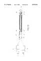
- FIG. 1is a schematic drawing of the probes of the present invention in use in the transperineal cryosurgical ablation of the prostate.
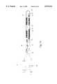
- FIG. 2is a view of the cryosurgical probe including the tubing connecting the probe to gas supplies.
- FIG. 3is a cross section of the cryosurgical probe adapted to provide a pear shaped iceball.
- FIG. 4is a cross section of the cryosurgical probe adapted to provide a oblong or olive-shaped iceball.
- FIG. 5is a cross section of the cryosurgical probe adapted to provide a spherical iceball.
- FIG. 6is a cross section of the cryosurgical probe adapted to provide cylindrical iceball.
- FIG. 7is a cross section of the cryosurgical probe with parallel fin tubing and flow directing sheaths located inside and outside the heat exchanger coil.
- FIG. 8is a cross section of the cryosurgical probe with parallel fin tubing.
- FIG. 9is a cross section of the cryosurgical probe with parallel fin tubing and offset dual Joule-Thomson nozzles.
- FIG. 10is a cross section of the cryosurgical probe with parallel fin tubing, adapted for use of one coil for cooling and one coil for heating.
- FIG. 11is a cross section of the cryosurgical probe with a helium Joule-Thomson nozzle.
- FIG. 12is a cross section of the cryosurgical probe with longitudinally offset heat exchangers for the cooling and warming gas flow.
- FIG. 13is a cross section of the cryosurgical probe with parallel fin tubing and a coaxial heating nozzle.
- FIG. 14is a cross section of the cryosurgical probe with longitudinally offset heat exchangers and longitudinally offset Joule-Thomson expansion nozzles.
- FIGS. 15 and 16schematics of the manifolds used for 5 operation of the cryosurgical probe.
- FIG. 1shows one of the basic operations for which the cryoprobes are designed.
- Several probes 1a, 1b, and 1care shown inserted in the prostate 2. All three probes are inserted through the perineal region 3 between the scrotum and the anus.
- Probe 1ais shown inserted into the anterior lobe 2b of the prostate, and Probes 1b and 1o are shown inserted into the posterior lobe 2a, which is larger than the anterior lobe.
- the probesare placed within the prostate according to procedures well known in the art, and a suitable procedure is described in step-by-step detail in Onik, et al., Percutaneous Prostate Cryoablation, (1995) at pages 108-112 and Onik, Ultrasound-Guided Cryosurgery Scientific American at 62. (January 1996).
- the urethra 4 which passes through the prostateis one of the anatomic structures that usually should not be frozen during this surgery. Accordingly, the urethra is protected and kept warm with the urethral warming catheter 5.
- the bladder neck sphincter 6 and the external sphincterare also structures that should be protected from freezing, and these are protected from freezing by the warming catheter. Neurovascular bundles on the right and left of the prostate should also be protected from freezing.
- Transrectal probe 8is inserted into the rectum 9 in order to visualize the placement of the probes and the growth of the iceballs formed by the cryoprobes.
- FIG. 2shows the entire cryosurgical probe assembly.
- the cryoprobe 1includes a cryocooler 10 about 25 cm (10 inches) long and 3.5 mm (0.134 in.) in diameter. These sizes are convenient and preferred for cryoprobes intended for prostate use, and may vary widely.
- the probe outer sheath 11houses the cryostat described in detail below.
- a handle 12 of convenient sizeis provided.
- the flexible tube 13houses gas supply lines 14 and thermocouple electrical wiring 15, and has a vent 16 for exhaust gas.
- the gas supply lineis connected to a high pressure gas supply through high pressure fitting 17.
- the thermocouple wireis connected to the control system through electrical connector 15.
- FIG. 3shows the basic embodiment of the cryosurgical probe.
- the high pressure gas supply line 14connects to the proximal extension 19 of the finned tube coiled heat exchanger 20.
- the heat exchangerextends longitudinally through the outer sheath 11 and connects to the cooling fluid outlet comprising distal extension 21 which open through Joule-Thomson nozzle 22 into expansion chamber 23.
- the expansion chamber size and shapeis controlled in part by the inner surface of the distal end plug and thermal barrier 24 which seals the outer sheath 11 and closes the distal end of the sheath.
- the outer sheathis made of thermally conductive material such as stainless steel.
- the end plugmay take many shapes but preferably has a rounded outer contour and a convex inner surface as shown.
- the end plugmay be made of stainless steel, or it may be made of tantalum, titanium, ceramic or other relatively insulating material to inhibit heat transfer from the tip of the probe.
- the heat exchangeris coiled around mandrel 25. The distal endpoint of the mandrel and the distal endpoint of the Joule-Thomson nozzle are equidistant from the end plug. In between each winding of the heat exchanger, gaps 26 are formed between the coil and the outer sheath, and gaps 27 are formed between the coil and the mandrel. This construction is known as a Giaque-Hampson heat exchanger.
- the heat exchangerwhich is an integral part of the high pressure gas pathway, is made with finned tubing, with numerous fins 28 throughout its length.
- the finned tubingis approximately 30 cm (12 inches) long and 0.75 mm (0.030 in.) in outer diameter and the fins are approximately 1 mm (0.0437 in.) in diameter.
- the finned tube coilis wrapped around the mandrel for 18 turns or so.
- the finsare stripped from the proximal extension for a length sufficient to allow insertion of the finned tubing into high pressure line 14 and soldering of the high pressure line to the finned tube.
- the mandrelis 0.75 mm. (032 in.) in outer diameter and 10 cm (3.75 in.) long.
- the Joule-Thomson nozzleis approximately 1.5 mm (0.0625 in.), with an internal diameter of 0.2 mm (0.008 in.).
- a thermocouple 29At the distal tip of the mandrel is a thermocouple 29 which is used to measure and monitor the temperature inside the cryosurgical probe.
- the flow directing sheath shown in FIG. 3is conveniently made of a heat shrink tube 3.25 cm (1.5 in.) long and 0.03 mm (1.75 mils) thick.
- the flow directing sheathsurrounds the heat exchanger coil and is generally coaxially disposed about the heat exchanger.
- the flow directing sheathprotrudes radially into the interstitial ridges between the windings or turns of the heat exchanger coil, as illustrated in FIG. 3 and the other figures illustrating the flow directing sheath.
- the flow directing sheathlengthens the gas flow path and forces gas to flow past the fins of the finned tube rather than flowing through the interstitial ridges between the turns of the helix.
- the sheath 30also serves as a thermal barrier, isolating and/or insulating the outer sheath 11 from the cold expanded gas flowing over the finned tube heat exchanger. This thermal barrier can be customized during manufacture to control the heat exchange characteristics of the probe and thereby control the shape of the iceball created by the probe.
- the length and number of windings covered by the flow directing sheath/thermal barrieris predetermined based on the desired iceball shape for which each probe is made.
- Fluid flow through the cryosurgical probeis as follows.
- High pressure fluidpreferably gaseous nitrogen or argon, and preferably at a pressure of about 3000 psi, is supplied to the assembly through high pressure fitting 17, flows through gas supply line 14, into heat exchanger 20 and through cooling fluid outlet 21 and Joule-Thomson nozzle 22.
- the high pressure gasexpands within the expansion chamber and cools to cryogenic temperatures. Condensation of the gas is preferably avoided but can be tolerated.
- the gasAfter expanding, the gas is at lower pressure and exhausts over the exhaust gas pathway which includes flow over outside of the coils of the heat exchanger 20. Because it is now cold, it cools the gas flowing inside the coils. This makes cooling more efficient and allows use of less gas.
- the gasWhile flowing over the outside of the finned tube, the gas is directed away from the inside of the outer sheath 11 thus preventing any significant heat exchange with the outer sheath.
- the exhaust gasAfter passing through the heat exchanger, the exhaust gas flows through the remainder of the exhaust gas pathway which includes the flexible tube and the vent 16 which vents the exhaust gas to atmosphere.
- FIG. 3the flow directing sheath covers the proximal portion 31 and central portion 32 of the heat exchanger, and the distal portion 33 of the heat exchanger is left uncovered.
- the distance L3 between the Joule-Thomson nozzle and the end of the heat exchange chamberis approximately 5 mm (0.2 in.).
- the length L2 of the distal extension 21 of the heat exchangeris approximately 7.5 mm (0.30 in.).
- the length of the heat exchanger coil L1is approximately 5 cm (2 in.).
- FIG. 3also includes a thermal insulating end plug made of a materiel that is less thermally conductive than the stainless steel outer sheath in order to block heat transfer at the distal tip of the probe and thereby promote a flatter bottom for the pear shaped iceball.
- the flow directing sheathis applied over substantially the entire length of the heat exchanger coil.
- the distance L3 between the Joule-Thomson nozzle and the end of the heat exchange chamberis approximately 5 mm (0.2 in.).
- the length L2 of the distal extension 21 of the heat exchangeris approximately 8 mm (0.3 in.). Operation of this cryosurgical probe within the body creates an iceball with a olive shape.
- the flow directing sheathis applied over substantially the entire length of the heat exchanger coil.
- the distance L3 between the Joule-Thomson nozzle and the end of the heat exchange chamberis approximately 2.5 mm (0.1 in.), significantly shorter than that shown for FIG. 4a.
- the length L2 of the distal extension 21 of the heat exchangeris approximately 5 mm (0.2 in.). Operation of this cryosurgical probe within the body creates an iceball with a olive shape.
- the flow directing sheathcovers only the proximal portion of the helical coil.
- the distance L3 between the Joule-Thomson nozzle and the end of the heat exchange chamberis significantly longer that that shown in FIG. 5, approximately 5 mm (0.2 in.).
- the length L2 of the distal extension 21 of the heat exchangeris approximately 12.5 mm (0.6 in.). Operation of this cryosurgical probe within the body will create an ice ball having a hot dog shape.
- FIG. 7Illustrated in FIG. 7 is an embodiment wherein the flow directing sheath is augmented with a second flow directing sheath 34 placed coaxially between the heat exchanger coils and the mandrel.
- the second flow directing sheathcan be made with impressible material such as teflon, or may be integrally formed with the mandril.
- the inside sheathblocks flow through the gaps between the coils and forces all gas flow to pass the fins, thus promoting heat transfer.
- the sheathsserve to block gas flow from flowing through the gaps between the windings and promotes more efficient heat exchange, a function previously accomplished by threads wrapped in the gaps, in parallel with the coils.
- FIG. 8shows a cryosurgical probe which includes two coiled heat exchangers and two Joule-Thomson nozzles. This dual helix cryosurgical probe produces large iceballs.
- the high pressure gas supply line 14 and finned tube helical coil heat exchanger 20are the same as those described in reference to the preceding figures.
- a second high pressure gas supply line 35, heat exchanger 36, gas outlet 37 and Joule-Thomson nozzle 38are provided. High pressure gas is expanded through both Joule-Thomson nozzles 22 and 38.
- the helical coilsare parallel to each other, meaning that the coils follow the same helical path around the mandrel.
- the cryosurgical probehaving two parallel helical coils with gas outlet that are equidistant from the distal tip of the probe is illustrated in FIG. 7. This probe produces a large spherical iceball, and with adjustment of the flow directing sheath can be modified to produce a pear shaped or tear-drop shape.
- the cryosurgical probehaving two parallel helical coils with gas outlets that are offset, with one gas outlet located distal of the other, and thus closer to the distal tip of the probe is illustrated in FIG. 9.
- This probe with offset Joule-Thomson nozzlesproduces a large hot dog shaped iceball.
- cryosurgical probesit is beneficial to have a means for warming the probe quickly. This is desired for therapeutic and practical reasons.
- Current theorysuggests that two cycles of rapid freezing and thawing provides better cryoablation than a single freeze. Practically, it can take a long time for the iceball to thaw so that the probe can be withdrawn from the body. Unless natural thawing is medically indicated, natural thawing is a waste of time.
- Prior art warming methodssuch as exhaust blocking, reverse flow heat transfer, and electrical heating can be employed.
- the preferred method of warmingis to supply high pressure helium gas through the supply line, heat exchanger and Joule-Thomson nozzle.
- Helium gasis one of the few gases that heat up when expanded through the gas outlet.
- the supply of gas to the probes shown in FIGS. 3 through 9can be switched from high pressure nitrogen or argon to high pressure helium to effect rapid rewarming of the catheter.
- the dual helix embodiment shown in FIGS. 8 and 9may be modified so that helium may be injected through one supply line aligned only to the helium gas supply, while the other supply line is used only for supply of high pressure cooling gas.
- This embodimentis shown in FIG. 10, which includes at the proximal end of the flexible tube a high pressure fitting 17 for the cooling gas (nitrogen, argon, CO 2 , etc.) to the cooling gas supply line 39 and a separate high pressure fitting 40 for helium supply to the warming gas supply line 41.
- the cooling gasnitrogen, argon, CO 2 , etc.
- one supply lineincluding the heat exchanger 20, gas outlet 21 and Joule-Thomson nozzle 22 is used to cool the probe with a cooling gas
- the second supply lineincluding heat exchanger 36, gas outlet and Joule-Thomson nozzle 38 is used to heat the probe with warming gas.
- the mandrel 25also houses a warming gas supply line 41 with a warming gas outlet 42 and Joule-Thomson nozzle 43 injected high pressure heating gas into expansion chamber 23.
- the warming gas supply line and warming gas outletextend longitudinally through the center of heat exchanger 20. Helium gas flowing out of the gas outlet into the expansion nozzle gets hotter when in expands and warms the probe. The hot expanded helium then flows proximally over the heat exchanger coils of the cooling gas supply line. However, while heating gas is supplied through heating gas supply line 14, no cooling gas is supplied to the cooling gas supply line. Because no heat exchanger is provided in the warming gas supply line 41, exhausted and hot warming gas does not exchange heat with incoming warming gas that is still at room temperature within the supply line.
- the warming gas heat exchanger 44is located several inches proximal of the coiled heat exchanger 20 in the cooling gas supply line.
- the warming gas outlet 42extends longitudinally through the cooling gas heat exchanger 20.
- the cryosurgical probe of FIG. 13combines the double helix design with the mandrel heating supply line.
- Cooling gas supply line 39supplies cooling gas to both helical coils through junction 45 and supply line branches 14a and 14b. Cooling gas is provided through single high pressure fitting 17.
- the warming gas supply line 41provides warming gas to the gas outlet 42 and Joule-Thomson nozzle 43 to warm the probe.
- FIG. 14illustrates another embodiment of a cryosurgical probe which provides cooling flow and warming flow.
- the heat exchanger 46, gas outlet 47 and Joule-Thomson nozzle 48 in the warming gas supply lineis located proximally of the heat exchanger 20, gas outlet 21 and Joule-Thomson nozzle 22 in the cooling gas supply line. This probe facilitates formation of oblong iceballs.
- the flow of warming gascan be adjusted and modified. As presented above, the warming gas flow provides heating or warming sufficient to rapidly heat the iceball and melt it.
- the warming gas flow pathwaymay be modified to create heating sufficient to cause thermal necrosis of surrounding tissue.
- the gas supply system for the cryoprobesis shown schematically in FIG. 15.
- High pressure cooling gasis stored in tank 49, and high pressure heating gas is stored in tank 50.
- Cooling gassuch as nitrogen or argon is stored in the flask at 6000 psi and stepped down to about 3200 psi by pressure regulator 51 and supplied to the gas regulating manifold 52.
- High pressure heating gas(helium) is stored in the flask at 3000 psi and passed through pressure regulator 51a to the gas regulating manifold.
- both supply linesare provided with filters 53 and 54 and banks 55 and 56 of solenoid operated cut-off valves.
- the cooling gas supply line regulator 51is set at 3000 psi.
- the heating gas supply line regulator 51ais set at 1000 psi. Both manifold supply lines 59 and 60 are provided with pressure reliefs 61 and 62 and various check valves as needed. Gas is supplied to the appropriate cryosurgical probes in gas dispensing manifolds.
- the cooling gas dispensing manifoldhas a manifold of solenoid operated valves 67 for supply of high pressure cooling gas from manifold supply line 59 to the probe supply lines 39.
- the heating gas manifold of solenoid operated valves 67supplies high pressure heating gas from the manifold supply line 60 to the various probe supply lines 39.
- eight individual probesare supplied. The probes cool and warm in response to cooling and warming gas through the probes, as controlled by the manifolds.
- the cooling of each cryosurgical probe in a set of probescan be independently controlled and the warming of each probe in the set of probes can be independently controlled.
- the dual manifoldcan be replaced by a series of three way valves which can alternatively connect the probe supply line 14 to the cooling or heating gases.
- FIG. 16shows a suitable manifold for independent control of cooling and warming of cryosurgical probes with separate supply lines for cooling and heating gases, such as the probes illustrated in FIGS. 9, 10 and 11.
- the cooling gas manifoldconnects the cooling gas manifold supply line to the various probe supply lines 39.
- the warming gas manifoldconnects the warming gas supply line to the various probe warming gas supply lines 41.
- the separate solenoid operated valvesmay be replaced with combination valves such as four way valves so that a single valve can be used to control flow of cooling gas and warming gas.
- cryoprobesIn the area of prostate cryoablation, several cryoprobes are used together in a single procedure. In the embodiment illustrated in FIGS. 15 and 16, eight cryoprobes are provided for each procedure. For a variety of reasons, it is beneficial to be able to cool each probe separately, and this feature is provided in current cryoablation systems. During the same procedure, it is also desirable to re-warm the cryosurgical probes independently, to protect anatomic features that seem in danger of freezing (as viewed in the transrectal ultrasound) or to change the position of a probe. The dual manifold illustrated in FIGS. 15 and 16 permit such independent control of the re-warming of the probes.
- the gases indicated for useinclude nitrogen, argon, NO 2 , and CO 2 for use as the cooling gas. These gases are preferred for their ready availability and safety. In theory, any gas which heats up when expanded may be used, and some environments may call for gasses such as oxygen, air, and other gasses.
- the gas indicated for coolingis preferably helium, but hydrogen and neon are also known to heat up when expanded and may be used in appropriate environments. Hydrogen and oxygen, we expect, will be avoided because their use in most environments will create an unacceptable risk of explosion.
- the device described abovehave been developed within the environment of cryosurgery, however the beneficial features will be useful in other environments of use such as electronics cooling and gas testing devices and other areas.
Landscapes
- Health & Medical Sciences (AREA)
- Engineering & Computer Science (AREA)
- Surgery (AREA)
- Life Sciences & Earth Sciences (AREA)
- Nuclear Medicine, Radiotherapy & Molecular Imaging (AREA)
- Biomedical Technology (AREA)
- Medical Informatics (AREA)
- Thermal Sciences (AREA)
- Otolaryngology (AREA)
- Mechanical Engineering (AREA)
- Physics & Mathematics (AREA)
- Heart & Thoracic Surgery (AREA)
- General Engineering & Computer Science (AREA)
- Molecular Biology (AREA)
- Animal Behavior & Ethology (AREA)
- General Health & Medical Sciences (AREA)
- Public Health (AREA)
- Veterinary Medicine (AREA)
- Surgical Instruments (AREA)
- Particle Accelerators (AREA)
- Steroid Compounds (AREA)
Abstract
Description
Claims (7)
Priority Applications (2)
| Application Number | Priority Date | Filing Date | Title |
|---|---|---|---|
| US09/143,925US6074412A (en) | 1996-07-23 | 1998-08-29 | Cryoprobe |
| US09/461,613US6505629B1 (en) | 1996-07-23 | 1999-12-15 | Cryosurgical system with protective warming feature |
Applications Claiming Priority (3)
| Application Number | Priority Date | Filing Date | Title |
|---|---|---|---|
| US08/685,233US5800487A (en) | 1996-07-23 | 1996-07-23 | Cryoprobe |
| US08/685,326US5800488A (en) | 1996-07-23 | 1996-07-23 | Cryoprobe with warming feature |
| US09/143,925US6074412A (en) | 1996-07-23 | 1998-08-29 | Cryoprobe |
Related Parent Applications (1)
| Application Number | Title | Priority Date | Filing Date |
|---|---|---|---|
| US08/685,233ContinuationUS5800487A (en) | 1996-07-23 | 1996-07-23 | Cryoprobe |
Related Child Applications (1)
| Application Number | Title | Priority Date | Filing Date |
|---|---|---|---|
| US09/461,613Continuation-In-PartUS6505629B1 (en) | 1996-07-23 | 1999-12-15 | Cryosurgical system with protective warming feature |
Publications (1)
| Publication Number | Publication Date |
|---|---|
| US6074412Atrue US6074412A (en) | 2000-06-13 |
Family
ID=27103539
Family Applications (3)
| Application Number | Title | Priority Date | Filing Date |
|---|---|---|---|
| US08/685,233Expired - LifetimeUS5800487A (en) | 1996-07-23 | 1996-07-23 | Cryoprobe |
| US08/685,326Expired - LifetimeUS5800488A (en) | 1996-07-23 | 1996-07-23 | Cryoprobe with warming feature |
| US09/143,925Expired - LifetimeUS6074412A (en) | 1996-07-23 | 1998-08-29 | Cryoprobe |
Family Applications Before (2)
| Application Number | Title | Priority Date | Filing Date |
|---|---|---|---|
| US08/685,233Expired - LifetimeUS5800487A (en) | 1996-07-23 | 1996-07-23 | Cryoprobe |
| US08/685,326Expired - LifetimeUS5800488A (en) | 1996-07-23 | 1996-07-23 | Cryoprobe with warming feature |
Country Status (8)
| Country | Link |
|---|---|
| US (3) | US5800487A (en) |
| EP (1) | EP0925045B1 (en) |
| JP (1) | JP2000516696A (en) |
| AT (1) | ATE237289T1 (en) |
| AU (1) | AU740358B2 (en) |
| CA (1) | CA2261177C (en) |
| DE (1) | DE69721015T2 (en) |
| WO (1) | WO1998004221A1 (en) |
Cited By (66)
| Publication number | Priority date | Publication date | Assignee | Title |
|---|---|---|---|---|
| WO2003024313A2 (en) | 2001-09-20 | 2003-03-27 | Endocare, Inc. | Malleable cryosurgical probe |
| US6585729B1 (en) | 1998-03-31 | 2003-07-01 | Endocare, Inc. | Vented cryosurgical system with backpressure source |
| US6648907B2 (en) | 2000-10-05 | 2003-11-18 | Seacoast Technologies, Inc. | Neurosurgical device for thermal therapy |
| US20040024392A1 (en)* | 2002-08-05 | 2004-02-05 | Lewis James D. | Apparatus and method for cryosurgery |
| WO2004012616A1 (en)* | 2002-08-06 | 2004-02-12 | Erbe Elektromedizin Gmbh | Cryo-surgical apparatus and method of use |
| US20040034321A1 (en)* | 2000-10-05 | 2004-02-19 | Seacoast Technologies, Inc. | Conformal pad for neurosurgery and method thereof |
| US20040082943A1 (en)* | 2002-10-04 | 2004-04-29 | Sanarusmedical, Inc. | Method and system for cryoablating fibroadenomas |
| US20040087876A1 (en)* | 2002-11-05 | 2004-05-06 | Scimed Life Systems, Inc. | Medical device having flexible distal tip |
| US20040095985A1 (en)* | 2002-11-15 | 2004-05-20 | Ko Kun Yuan | Dual-use infrared thermometer |
| US6767346B2 (en) | 2001-09-20 | 2004-07-27 | Endocare, Inc. | Cryosurgical probe with bellows shaft |
| US20040204705A1 (en)* | 2003-04-10 | 2004-10-14 | Scimed Life Systems, Inc. | Cryotreatment devices and methods of forming conduction blocks |
| US20040215177A1 (en)* | 2003-04-24 | 2004-10-28 | Scimed Life Systems, Inc. | Therapeutic apparatus having insulated region at the insertion area |
| US20040215294A1 (en)* | 2003-01-15 | 2004-10-28 | Mediphysics Llp | Cryotherapy probe |
| US20040226354A1 (en)* | 2003-05-14 | 2004-11-18 | Roland Schmidt | Method and device for the measurement of exhaust gas from internal combustion engines |
| US20050034274A1 (en)* | 2003-08-12 | 2005-02-17 | Wu Ching Sung | Hinge |
| US20050038422A1 (en)* | 2002-08-06 | 2005-02-17 | Medically Advanced Designs, Llc | Cryo-surgical apparatus and methods |
| US20050043724A1 (en)* | 2003-08-22 | 2005-02-24 | Eric Ryba | Reshapeable tip for a cryoprobe |
| US20050043725A1 (en)* | 2003-06-25 | 2005-02-24 | Thach Duong | Threaded cryostat for cryosurgical probe system |
| US20050177209A1 (en)* | 2002-03-05 | 2005-08-11 | Baylis Medical Company Inc. | Bipolar tissue treatment system |
| US20050177210A1 (en)* | 2002-03-05 | 2005-08-11 | Baylis Medical Company Inc. | Electrosurgical tissue treatment method |
| US20050177211A1 (en)* | 2002-03-05 | 2005-08-11 | Baylis Medical Company Inc. | Electrosurgical device for treatment of tissue |
| US20050192565A1 (en)* | 2003-06-25 | 2005-09-01 | Endocare, Inc. | Detachable cryosurgical probe with breakaway handle |
| US20050234445A1 (en)* | 2002-03-05 | 2005-10-20 | Baylis Medical Company Inc. | Method of treating biological tissue |
| US20050261753A1 (en)* | 2003-01-15 | 2005-11-24 | Mediphysics Llp | Methods and systems for cryogenic cooling |
| US20060079867A1 (en)* | 2003-04-03 | 2006-04-13 | Nir Berzak | Apparatus and method for accurately delimited cryoablation |
| US7083612B2 (en) | 2003-01-15 | 2006-08-01 | Cryodynamics, Llc | Cryotherapy system |
| US20060264920A1 (en)* | 2005-05-19 | 2006-11-23 | Endocare, Inc. | Cryosurgical probe assembly with multiple deployable cryoprobes |
| US20070088386A1 (en)* | 2005-10-18 | 2007-04-19 | Babaev Eilaz P | Apparatus and method for treatment of soft tissue injuries |
| US20070088217A1 (en)* | 2005-10-13 | 2007-04-19 | Babaev Eilaz P | Apparatus and methods for the selective removal of tissue using combinations of ultrasonic energy and cryogenic energy |
| US20070149959A1 (en)* | 2005-12-23 | 2007-06-28 | Sanarus Medical, Inc. | Cryoprobe for low pressure systems |
| US20070156125A1 (en)* | 2005-12-30 | 2007-07-05 | Russell Delonzor | Encodable cryogenic device |
| US20070167776A1 (en)* | 2005-12-15 | 2007-07-19 | Galil Medical Ltd. | Method and apparatus for protecting the rectal wall during cryoablation |
| US20070167939A1 (en)* | 2003-06-25 | 2007-07-19 | Endocare, Inc. | Quick disconnect assembly having a finger lock assembly |
| US20070191824A1 (en)* | 2003-06-25 | 2007-08-16 | Endocare, Inc. | Detachable cryosurgical probe |
| US20080306475A1 (en)* | 2007-06-08 | 2008-12-11 | Lentz David J | Cryo-applicator cross-section configuration |
| US7540870B2 (en) | 2006-08-08 | 2009-06-02 | Bacoustics, Llc | Ablative ultrasonic-cryogenic apparatus |
| US20090221955A1 (en)* | 2006-08-08 | 2009-09-03 | Bacoustics, Llc | Ablative ultrasonic-cryogenic methods |
| US7608071B2 (en) | 2003-06-25 | 2009-10-27 | Endocare, Inc. | Cryosurgical probe with adjustable sliding apparatus |
| US20100241114A1 (en)* | 2009-03-20 | 2010-09-23 | Salvatore Privitera | Cryogenic probe |
| US7842032B2 (en) | 2005-10-13 | 2010-11-30 | Bacoustics, Llc | Apparatus and methods for the selective removal of tissue |
| WO2010127189A3 (en)* | 2009-04-30 | 2011-03-31 | Cryomedix Llc | Cryoablation system having docking station for charging cryogen containers and related method |
| US20110245821A1 (en)* | 2010-03-30 | 2011-10-06 | Medtronic ATS Medical, Inc. | Cryoprobe having internal warming fluid capabilities |
| US8187260B1 (en) | 2006-12-29 | 2012-05-29 | Endocare, Inc. | Variable cryosurgical probe planning system |
| US8518036B2 (en) | 2002-03-05 | 2013-08-27 | Kimberly-Clark Inc. | Electrosurgical tissue treatment method |
| RU2497477C2 (en)* | 2010-08-04 | 2013-11-10 | Эрбе Электромедицин Гмбх | Handle for surgical instrument, in particular cryosurgical instrument |
| RU2500437C2 (en)* | 2010-08-18 | 2013-12-10 | Эрбе Электромедицин Гмбх | Device for tight connection of pressure hose and gripping element or surgical tool connector |
| RU2500364C2 (en)* | 2010-08-18 | 2013-12-10 | Эрбе Электромедицин Гмбх | Device for connection of at least one application probe, transferring flowing medium, with system of supplying tubes, and handle for surgical instrument |
| CN103442657A (en)* | 2011-05-11 | 2013-12-11 | 艾斯酷瑞医药有限公司 | Coiled heat exchanger for cryosurgical instrument |
| US9474573B2 (en) | 2002-03-05 | 2016-10-25 | Avent, Inc. | Electrosurgical tissue treatment device |
| US9486275B2 (en) | 2010-12-30 | 2016-11-08 | Avent, Inc. | Electrosurgical apparatus having a sensor |
| CN106456230A (en)* | 2014-03-11 | 2017-02-22 | 艾斯酷瑞医药有限公司 | Phase separation of cryogens in cryosurgical instruments |
| US10390871B2 (en) | 2015-02-20 | 2019-08-27 | Galil Medical Inc. | Cryoneedle |
| US10543032B2 (en) | 2014-11-13 | 2020-01-28 | Adagio Medical, Inc. | Pressure modulated cryoablation system and related methods |
| US10617459B2 (en) | 2014-04-17 | 2020-04-14 | Adagio Medical, Inc. | Endovascular near critical fluid based cryoablation catheter having plurality of preformed treatment shapes |
| US10667854B2 (en) | 2013-09-24 | 2020-06-02 | Adagio Medical, Inc. | Endovascular near critical fluid based cryoablation catheter and related methods |
| WO2020180686A1 (en) | 2019-03-01 | 2020-09-10 | Rampart Health, L.L.C. | Pharmaceutical composition combining immunologic and chemotherapeutic method for the treatment of cancer |
| US10864031B2 (en) | 2015-11-30 | 2020-12-15 | Adagio Medical, Inc. | Ablation method for creating elongate continuous lesions enclosing multiple vessel entries |
| US11051867B2 (en) | 2015-09-18 | 2021-07-06 | Adagio Medical, Inc. | Tissue contact verification system |
| WO2022174064A2 (en) | 2021-02-12 | 2022-08-18 | Rampart Health, L.L.C. | Therapeutic composition and method combining multiplex immunotherapy with cancer vaccine for the treatment of cancer |
| US11446074B2 (en) | 2017-11-13 | 2022-09-20 | Biocompatibles Uk Limited | Cryoablation system with magnetic resonance imaging detection |
| US11564725B2 (en) | 2017-09-05 | 2023-01-31 | Adagio Medical, Inc. | Ablation catheter having a shape memory stylet |
| US11633224B2 (en) | 2020-02-10 | 2023-04-25 | Icecure Medical Ltd. | Cryogen pump |
| US11751930B2 (en) | 2018-01-10 | 2023-09-12 | Adagio Medical, Inc. | Cryoablation element with conductive liner |
| US12016607B2 (en) | 2017-11-13 | 2024-06-25 | Biocompatibles Uk Limited | Cryoprobe for magnetic resonance imaging |
| US12215811B2 (en) | 2022-07-18 | 2025-02-04 | Icecure Medical Ltd. | Cryogenic system connector |
| US12426934B2 (en) | 2022-02-28 | 2025-09-30 | Icecure Medical Ltd. | Cryogen flow control |
Families Citing this family (103)
| Publication number | Priority date | Publication date | Assignee | Title |
|---|---|---|---|---|
| US5910104A (en)* | 1996-12-26 | 1999-06-08 | Cryogen, Inc. | Cryosurgical probe with disposable sheath |
| US7255693B1 (en)* | 1997-05-23 | 2007-08-14 | Csa Medical, Inc. | Heated catheter used in cryotherapy |
| JP2001517475A (en)* | 1997-09-22 | 2001-10-09 | エシコン・インコーポレイテッド | Cryosurgery system and method |
| US6190378B1 (en)* | 1997-12-05 | 2001-02-20 | Massachusetts Institute Of Technology | Cryosurgical instrument and related techniques |
| US6464716B1 (en) | 1998-01-23 | 2002-10-15 | Innercool Therapies, Inc. | Selective organ cooling apparatus and method |
| US6261312B1 (en) | 1998-06-23 | 2001-07-17 | Innercool Therapies, Inc. | Inflatable catheter for selective organ heating and cooling and method of using the same |
| US6096068A (en) | 1998-01-23 | 2000-08-01 | Innercool Therapies, Inc. | Selective organ cooling catheter and method of using the same |
| US6231595B1 (en) | 1998-03-31 | 2001-05-15 | Innercool Therapies, Inc. | Circulating fluid hypothermia method and apparatus |
| US6585752B2 (en) | 1998-06-23 | 2003-07-01 | Innercool Therapies, Inc. | Fever regulation method and apparatus |
| US6325818B1 (en) | 1999-10-07 | 2001-12-04 | Innercool Therapies, Inc. | Inflatable cooling apparatus for selective organ hypothermia |
| US7371254B2 (en) | 1998-01-23 | 2008-05-13 | Innercool Therapies, Inc. | Medical procedure |
| US6379378B1 (en) | 2000-03-03 | 2002-04-30 | Innercool Therapies, Inc. | Lumen design for catheter |
| US6471717B1 (en) | 1998-03-24 | 2002-10-29 | Innercool Therapies, Inc. | Selective organ cooling apparatus and method |
| US6312452B1 (en) | 1998-01-23 | 2001-11-06 | Innercool Therapies, Inc. | Selective organ cooling catheter with guidewire apparatus and temperature-monitoring device |
| US6602276B2 (en) | 1998-03-31 | 2003-08-05 | Innercool Therapies, Inc. | Method and device for performing cooling- or cryo-therapies for, e.g., angioplasty with reduced restenosis or pulmonary vein cell necrosis to inhibit atrial fibrillation |
| US7001378B2 (en)* | 1998-03-31 | 2006-02-21 | Innercool Therapies, Inc. | Method and device for performing cooling or cryo-therapies, for, e.g., angioplasty with reduced restenosis or pulmonary vein cell necrosis to inhibit atrial fibrillation employing tissue protection |
| US7291144B2 (en) | 1998-03-31 | 2007-11-06 | Innercool Therapies, Inc. | Method and device for performing cooling- or cryo-therapies for, e.g., angioplasty with reduced restenosis or pulmonary vein cell necrosis to inhibit atrial fibrillation |
| US6905494B2 (en) | 1998-03-31 | 2005-06-14 | Innercool Therapies, Inc. | Method and device for performing cooling- or cryo-therapies for, e.g., angioplasty with reduced restenosis or pulmonary vein cell necrosis to inhibit atrial fibrillation employing tissue protection |
| US6685732B2 (en) | 1998-03-31 | 2004-02-03 | Innercool Therapies, Inc. | Method and device for performing cooling- or cryo-therapies for, e.g., angioplasty with reduced restenosis or pulmonary vein cell necrosis to inhibit atrial fibrillation employing microporous balloon |
| US6106518A (en)* | 1998-04-09 | 2000-08-22 | Cryocath Technologies, Inc. | Variable geometry tip for a cryosurgical ablation device |
| US6338727B1 (en) | 1998-08-13 | 2002-01-15 | Alsius Corporation | Indwelling heat exchange catheter and method of using same |
| GB2336781B (en)* | 1998-04-30 | 2001-03-07 | Spembly Medical Ltd | Cryosurgical apparatus |
| WO1999065410A1 (en)* | 1998-06-19 | 1999-12-23 | Endocare, Inc. | Sheath, cryoprobe, and methods for use |
| FR2782785B1 (en)* | 1998-08-27 | 2001-01-19 | Air Liquide | JOULE-THOMSON COOLER |
| US6241718B1 (en) | 1998-11-30 | 2001-06-05 | Cryocath Technologies, Inc. | Method for inhibiting restenosis |
| US6575933B1 (en) | 1998-11-30 | 2003-06-10 | Cryocath Technologies Inc. | Mechanical support for an expandable membrane |
| GB2344873A (en)* | 1998-12-14 | 2000-06-21 | Spembly Medical Ltd | Cryogen supply apparatus |
| US6546932B1 (en)* | 1999-04-05 | 2003-04-15 | Cryocath Technologies Inc. | Cryogenic method and apparatus for promoting angiogenesis |
| US7363071B2 (en) | 1999-05-26 | 2008-04-22 | Endocare, Inc. | Computer guided ablation of tissue using integrated ablative/temperature sensing devices |
| US6694170B1 (en)* | 1999-05-26 | 2004-02-17 | Endocare, Inc. | Computer guided surgery for prostatic nerve sparing |
| US6280439B1 (en) | 1999-07-12 | 2001-08-28 | Cryocath Technologies, Inc. | Adjustable position injection tubing |
| US6270493B1 (en) | 1999-07-19 | 2001-08-07 | Cryocath Technologies, Inc. | Cryoablation structure |
| US7097641B1 (en)* | 1999-12-09 | 2006-08-29 | Cryocath Technologies Inc. | Catheter with cryogenic and heating ablation |
| US6497703B1 (en) | 2000-03-02 | 2002-12-24 | Biosense Webster | Cryoablation catheter for long lesion ablations |
| WO2002009571A2 (en)* | 2000-07-31 | 2002-02-07 | Galil Medical Ltd. | Planning and facilitation systems and methods for cryosurgery |
| US6551309B1 (en)* | 2000-09-14 | 2003-04-22 | Cryoflex, Inc. | Dual action cryoprobe and methods of using the same |
| US20020068929A1 (en)* | 2000-10-24 | 2002-06-06 | Roni Zvuloni | Apparatus and method for compressing a gas, and cryosurgery system and method utilizing same |
| US20020188287A1 (en)* | 2001-05-21 | 2002-12-12 | Roni Zvuloni | Apparatus and method for cryosurgery within a body cavity |
| US20080045934A1 (en)* | 2000-10-24 | 2008-02-21 | Galil Medical Ltd. | Device and method for coordinated insertion of a plurality of cryoprobes |
| US6706037B2 (en) | 2000-10-24 | 2004-03-16 | Galil Medical Ltd. | Multiple cryoprobe apparatus and method |
| US6719723B2 (en) | 2000-12-06 | 2004-04-13 | Innercool Therapies, Inc. | Multipurpose catheter assembly |
| US6450987B1 (en) | 2001-02-01 | 2002-09-17 | Innercool Therapies, Inc. | Collapsible guidewire lumen |
| US20080051776A1 (en)* | 2001-05-21 | 2008-02-28 | Galil Medical Ltd. | Thin uninsulated cryoprobe and insulating probe introducer |
| US20080051774A1 (en)* | 2001-05-21 | 2008-02-28 | Galil Medical Ltd. | Device and method for coordinated insertion of a plurality of cryoprobes |
| CA2461627A1 (en)* | 2001-09-27 | 2003-04-03 | Roni Zvuloni | Apparatus and method for cryosurgical treatment of tumors of the breast |
| US6589234B2 (en) | 2001-09-27 | 2003-07-08 | Cryocath Technologies Inc. | Cryogenic medical device with high pressure resistance tip |
| WO2003026719A2 (en)* | 2001-09-27 | 2003-04-03 | Galil Medical Ltd. | Cryoplasty apparatus and method |
| WO2003033050A1 (en) | 2001-10-12 | 2003-04-24 | Applied Medical Resources Corporation | High-flow low-pressure irrigation system |
| JP4309281B2 (en)* | 2002-01-04 | 2009-08-05 | ガリル メディカル リミテッド | Apparatus and method for protecting neurovascular bundles during cryosurgical treatment of the prostate |
| US7479139B2 (en)* | 2002-01-04 | 2009-01-20 | Galil Medical Ltd. | Apparatus and method for protecting tissues during cryoablation |
| CA2931693C (en) | 2003-01-15 | 2017-03-14 | Cryodynamics, Llc | Cryotherapy probe and system |
| CA2522939A1 (en)* | 2003-04-21 | 2004-11-04 | Galil Medical Ltd. | Apparatus and method positioning a therapeutic probe with respect to a therapeutic target |
| US20040220557A1 (en)* | 2003-04-30 | 2004-11-04 | Eum Jay J. | Closed system warming catheter and method of use |
| US8007847B2 (en) | 2004-01-13 | 2011-08-30 | Eytan Biderman | Feeding formula appliance |
| CN100591299C (en)* | 2004-09-20 | 2010-02-24 | 厄比电子医学有限责任公司 | Cryosurgery apparatus and method |
| US20060084939A1 (en)* | 2004-10-20 | 2006-04-20 | Lentz David J | Articulation segment for a catheter |
| US20060178662A1 (en)* | 2005-02-04 | 2006-08-10 | Ripley Kenneth L | Warming gradient control for a cryoablation applicator |
| WO2007069248A2 (en)* | 2005-12-16 | 2007-06-21 | Galil Medical Ltd. | Apparatus and method for thermal ablation of uterine fibroids |
| US20070244474A1 (en)* | 2006-04-18 | 2007-10-18 | Sanarus Medical, Inc. | Cryosurgical system |
| US20070149957A1 (en)* | 2005-12-23 | 2007-06-28 | Sanarus Medical, Inc. | Low pressure liquid nitrogen cryosurgical system |
| US20090292279A1 (en)* | 2006-01-26 | 2009-11-26 | Galil Medical Ltd. | Device and Method for Coordinated Insertion of a Plurality of Cryoprobes |
| WO2007129308A2 (en)* | 2006-05-02 | 2007-11-15 | Galil Medical Ltd. | Cryotherapy planning and control system |
| WO2008099490A1 (en)* | 2007-02-15 | 2008-08-21 | Dgs Computer | Medical device and medical apparatus to be used in freezing therapy |
| JP2008245954A (en)* | 2007-03-30 | 2008-10-16 | Dgs Computer:Kk | Cryogenic medical instrument |
| US7976538B2 (en)* | 2007-04-16 | 2011-07-12 | Sanarus Technologies, Llc | Fast fibroadenoma treatment system and method |
| US8092448B2 (en)* | 2007-04-16 | 2012-01-10 | Sanarus Technologies, Llc | Cryosurgical system with low pressure cryogenic fluid supply |
| WO2009128014A1 (en)* | 2008-04-16 | 2009-10-22 | Arbel Medical Ltd | Cryosurgical instrument with enhanced heat exchange |
| US8814850B2 (en)* | 2008-04-24 | 2014-08-26 | Cryomedix, Llc | Method and system for cryoablation treatment |
| US9050069B2 (en) | 2008-05-16 | 2015-06-09 | Medtronic Cryocath Lp | Thermocouple-controlled catheter cooling system |
| JP5233031B2 (en)* | 2008-07-15 | 2013-07-10 | 株式会社デージーエス・コンピュータ | Cryotherapy planning device and cryotherapy device |
| US8845627B2 (en)* | 2008-08-22 | 2014-09-30 | Boston Scientific Scimed, Inc. | Regulating pressure to lower temperature in a cryotherapy balloon catheter |
| US8382746B2 (en) | 2008-11-21 | 2013-02-26 | C2 Therapeutics, Inc. | Cryogenic ablation system and method |
| WO2010083281A1 (en)* | 2009-01-15 | 2010-07-22 | Boston Scientific Scimed, Inc. | Controlling depth of cryoablation |
| US7967814B2 (en) | 2009-02-05 | 2011-06-28 | Icecure Medical Ltd. | Cryoprobe with vibrating mechanism |
| US8162812B2 (en) | 2009-03-12 | 2012-04-24 | Icecure Medical Ltd. | Combined cryotherapy and brachytherapy device and method |
| US20100241113A1 (en)* | 2009-03-20 | 2010-09-23 | Boston Scientific Scimed, Inc. | Protecting the phrenic nerve while ablating cardiac tissue |
| WO2010144811A1 (en)* | 2009-06-11 | 2010-12-16 | Florida State University | Zero delta temperature thermal link |
| US8591504B2 (en)* | 2009-07-31 | 2013-11-26 | Boston Scientific Scimed, Inc. | Systems and methods for regulating pressure levels in an inter-expansion-element space of a cryoablation system |
| WO2011037235A1 (en)* | 2009-09-28 | 2011-03-31 | 株式会社アドメテック | Living body heating device and temperature control method |
| US7967815B1 (en) | 2010-03-25 | 2011-06-28 | Icecure Medical Ltd. | Cryosurgical instrument with enhanced heat transfer |
| US7938822B1 (en) | 2010-05-12 | 2011-05-10 | Icecure Medical Ltd. | Heating and cooling of cryosurgical instrument using a single cryogen |
| US8080005B1 (en) | 2010-06-10 | 2011-12-20 | Icecure Medical Ltd. | Closed loop cryosurgical pressure and flow regulated system |
| EP4032486A1 (en) | 2010-11-16 | 2022-07-27 | TVA Medical, Inc. | Devices for forming a fistula |
| WO2012121786A1 (en)* | 2011-03-09 | 2012-09-13 | Icecure Medical Ltd. | Cryosurgical instrument with redirected flow |
| US9039689B2 (en) | 2011-05-11 | 2015-05-26 | Icecure Medical Ltd. | Phase separation of cryogen in cryosurgical instrument |
| US9486276B2 (en) | 2012-10-11 | 2016-11-08 | Tva Medical, Inc. | Devices and methods for fistula formation |
| ITFI20120226A1 (en)* | 2012-10-25 | 2014-04-26 | Era Endoscopy S R L | TUBULAR GUIDE FLEXIBLE AND EXTENSIBLE AND ITS MANUFACTURING PROCEDURE |
| CN105228683B (en) | 2013-03-14 | 2022-06-10 | Tva医疗公司 | Fistula-forming device and method for forming fistula |
| US10695534B2 (en) | 2014-03-14 | 2020-06-30 | Tva Medical, Inc. | Fistula formation devices and methods therefor |
| WO2016033374A1 (en)* | 2014-08-27 | 2016-03-03 | Tva Medical, Inc. | Cryolipopysis devices and methods therefor |
| US10603040B1 (en) | 2015-02-09 | 2020-03-31 | Tva Medical, Inc. | Methods for treating hypertension and reducing blood pressure with formation of fistula |
| US9414878B1 (en) | 2015-05-15 | 2016-08-16 | C2 Therapeutics, Inc. | Cryogenic balloon ablation system |
| WO2017124062A1 (en) | 2016-01-15 | 2017-07-20 | Tva Medical, Inc. | Devices and methods for forming a fistula |
| US10874422B2 (en) | 2016-01-15 | 2020-12-29 | Tva Medical, Inc. | Systems and methods for increasing blood flow |
| CN114042224B (en) | 2016-01-15 | 2024-09-17 | Tva医疗公司 | Device and method for advancing a wire |
| JP7219090B2 (en) | 2016-01-15 | 2023-02-07 | ティーブイエー メディカル, インコーポレイテッド | Systems and methods for gluing vessels |
| JP7021113B2 (en) | 2016-05-20 | 2022-02-16 | ペンタックス・オブ・アメリカ・インコーポレイテッド | Cryogenic excision system with rotatable and translatable catheter |
| CN109982652B (en) | 2016-09-25 | 2022-08-05 | Tva医疗公司 | Vascular stent device and method |
| PL3437579T3 (en)* | 2017-08-04 | 2023-10-16 | Erbe Elektromedizin Gmbh | Cryosurgical instrument |
| WO2020150255A1 (en) | 2019-01-14 | 2020-07-23 | Cryoelectric Science Ltd. | Methods, systems, and apparatuses for cryosurgery, coldsurgery, and electrolysis |
| US20200345403A1 (en)* | 2019-05-03 | 2020-11-05 | The Board Of Trustees Of The Leland Stanford Junior University | Instruments and methodology involving cryoablation |
| US11021259B1 (en) | 2021-01-07 | 2021-06-01 | Philip Onni Jarvinen | Aircraft exhaust mitigation system and process |
| CN115192174B (en)* | 2021-06-30 | 2023-04-07 | 海杰亚(北京)医疗器械有限公司 | Method and device for adjusting pressure in working medium storage tank |
Citations (18)
| Publication number | Priority date | Publication date | Assignee | Title |
|---|---|---|---|---|
| US3398738A (en)* | 1964-09-24 | 1968-08-27 | Aerojet General Co | Refrigerated surgical probe |
| US3658066A (en)* | 1970-03-09 | 1972-04-25 | Farrokh Saidi | Cryosurgical appliance |
| US3800552A (en)* | 1972-03-29 | 1974-04-02 | Bendix Corp | Cryogenic surgical instrument |
| US3913581A (en)* | 1972-06-02 | 1975-10-21 | Spembly Ltd | Cryogenic apparatus |
| US4028907A (en)* | 1975-12-15 | 1977-06-14 | Texas Instruments Incorporated | Adjustable-Joule-Thomson cryogenic cooler with downstream thermal compensation |
| US4063560A (en)* | 1975-04-22 | 1977-12-20 | Spembly Limited | Cryosurgical instrument |
| US4306568A (en)* | 1979-12-04 | 1981-12-22 | Torre Douglas P | Method and apparatus for congelation cryometry in cryosurgery |
| US4486935A (en)* | 1982-02-23 | 1984-12-11 | Toyota Jidosha Kabushiki Kaisha | Coil spring compressor for use in the assembly of automotive suspension systems |
| SU1217377A1 (en)* | 1984-06-04 | 1986-03-15 | Физико-технический институт низких температур АН УССР | Method of thawing out cryosurgical instrument |
| US4946460A (en)* | 1989-04-26 | 1990-08-07 | Cryo Instruments, Inc. | Apparatus for cryosurgery |
| US5018713A (en)* | 1989-09-15 | 1991-05-28 | Eastman Machine Company | Cloth-spreading apparatus having improved control means |
| US5077979A (en)* | 1990-03-22 | 1992-01-07 | Hughes Aircraft Company | Two-stage joule-thomson cryostat with gas supply management system, and uses thereof |
| US5108390A (en)* | 1988-11-14 | 1992-04-28 | Frigitronics, Inc. | Flexible cryoprobe |
| US5150579A (en)* | 1989-12-14 | 1992-09-29 | Bodenseewerk Geratetechnik Gmbh | Two stage cooler for cooling an object |
| EP0608927A2 (en)* | 1993-01-25 | 1994-08-03 | State of Israel Ministry of Defence Raphael Armament Development Authority | Fast changing heating-cooling device and method |
| US5388415A (en)* | 1993-01-24 | 1995-02-14 | State Of Israel - Ministry Of Defence Armament Development Authority, Rafael | System for a cooler and gas purity tester |
| US5452582A (en)* | 1994-07-06 | 1995-09-26 | Apd Cryogenics, Inc. | Cryo-probe |
| US5993444A (en)* | 1997-12-02 | 1999-11-30 | Galil Medical Ltd. | Method and device for trans myocardial cryo revascularization |
Family Cites Families (7)
| Publication number | Priority date | Publication date | Assignee | Title |
|---|---|---|---|---|
| GB2094636A (en)* | 1981-03-12 | 1982-09-22 | Spembly Ltd | A cryosurgical probe |
| FR2520131B1 (en)* | 1982-01-19 | 1985-09-20 | Telecommunications Sa | REGULATION DEVICE FOR A JOULE-THOMSON EFFECT REFRIGERATOR |
| FR2568357B1 (en)* | 1984-07-25 | 1987-01-30 | Air Liquide | JOULE-THOMSON COOLING METHOD AND PROBE |
| GB2226497B (en)* | 1988-12-01 | 1992-07-01 | Spembly Medical Ltd | Cryosurgical probe |
| US5254116A (en)* | 1991-09-06 | 1993-10-19 | Cryomedical Sciences, Inc. | Cryosurgical instrument with vent holes and method using same |
| GB9123413D0 (en)* | 1991-11-05 | 1991-12-18 | Clarke Brian K R | Method of thawing cryosurgical apparatus |
| IL110176A (en)* | 1994-06-30 | 1999-12-31 | Israel State | Multiprobe surgical cryogenic apparatus |
- 1996
- 1996-07-23USUS08/685,233patent/US5800487A/ennot_activeExpired - Lifetime
- 1996-07-23USUS08/685,326patent/US5800488A/ennot_activeExpired - Lifetime
- 1997
- 1997-07-21AUAU38065/97Apatent/AU740358B2/ennot_activeCeased
- 1997-07-21CACA002261177Apatent/CA2261177C/ennot_activeExpired - Lifetime
- 1997-07-21ATAT97935033Tpatent/ATE237289T1/ennot_activeIP Right Cessation
- 1997-07-21WOPCT/US1997/012719patent/WO1998004221A1/enactiveIP Right Grant
- 1997-07-21JPJP10508907Apatent/JP2000516696A/ennot_activeCeased
- 1997-07-21EPEP97935033Apatent/EP0925045B1/ennot_activeExpired - Lifetime
- 1997-07-21DEDE69721015Tpatent/DE69721015T2/ennot_activeExpired - Lifetime
- 1998
- 1998-08-29USUS09/143,925patent/US6074412A/ennot_activeExpired - Lifetime
Patent Citations (19)
| Publication number | Priority date | Publication date | Assignee | Title |
|---|---|---|---|---|
| US3398738A (en)* | 1964-09-24 | 1968-08-27 | Aerojet General Co | Refrigerated surgical probe |
| US3658066A (en)* | 1970-03-09 | 1972-04-25 | Farrokh Saidi | Cryosurgical appliance |
| US3800552A (en)* | 1972-03-29 | 1974-04-02 | Bendix Corp | Cryogenic surgical instrument |
| US3913581A (en)* | 1972-06-02 | 1975-10-21 | Spembly Ltd | Cryogenic apparatus |
| US4063560A (en)* | 1975-04-22 | 1977-12-20 | Spembly Limited | Cryosurgical instrument |
| US4028907A (en)* | 1975-12-15 | 1977-06-14 | Texas Instruments Incorporated | Adjustable-Joule-Thomson cryogenic cooler with downstream thermal compensation |
| US4306568A (en)* | 1979-12-04 | 1981-12-22 | Torre Douglas P | Method and apparatus for congelation cryometry in cryosurgery |
| US4486935A (en)* | 1982-02-23 | 1984-12-11 | Toyota Jidosha Kabushiki Kaisha | Coil spring compressor for use in the assembly of automotive suspension systems |
| SU1217377A1 (en)* | 1984-06-04 | 1986-03-15 | Физико-технический институт низких температур АН УССР | Method of thawing out cryosurgical instrument |
| US5108390A (en)* | 1988-11-14 | 1992-04-28 | Frigitronics, Inc. | Flexible cryoprobe |
| US4946460A (en)* | 1989-04-26 | 1990-08-07 | Cryo Instruments, Inc. | Apparatus for cryosurgery |
| US5018713A (en)* | 1989-09-15 | 1991-05-28 | Eastman Machine Company | Cloth-spreading apparatus having improved control means |
| US5150579A (en)* | 1989-12-14 | 1992-09-29 | Bodenseewerk Geratetechnik Gmbh | Two stage cooler for cooling an object |
| US5077979A (en)* | 1990-03-22 | 1992-01-07 | Hughes Aircraft Company | Two-stage joule-thomson cryostat with gas supply management system, and uses thereof |
| US5388415A (en)* | 1993-01-24 | 1995-02-14 | State Of Israel - Ministry Of Defence Armament Development Authority, Rafael | System for a cooler and gas purity tester |
| EP0608927A2 (en)* | 1993-01-25 | 1994-08-03 | State of Israel Ministry of Defence Raphael Armament Development Authority | Fast changing heating-cooling device and method |
| US5522870A (en)* | 1993-01-25 | 1996-06-04 | State Of Israel, Ministry Of Defense, Rafael-Armaments Development Authority | Fast changing heating-cooling device and method |
| US5452582A (en)* | 1994-07-06 | 1995-09-26 | Apd Cryogenics, Inc. | Cryo-probe |
| US5993444A (en)* | 1997-12-02 | 1999-11-30 | Galil Medical Ltd. | Method and device for trans myocardial cryo revascularization |
Non-Patent Citations (6)
| Title |
|---|
| Onik et al, Percutaneous Prostate Cryoablation (1995).* |
| Onik et al., Transrectal Ultrasound Guided Percutaneous Radial Cryosurgical Ablation of the Prostate, 72 Cancer 1291 (1993).* |
| Onik et al., Transrectal Ultrasound-Guided Percutaneous Radial Cryosurgical Ablation of the Prostate, 72 Cancer 1291 (1993). |
| Onik, Ultrasound Guided Cryosurgery, Scientific American at 62 (Jan. 1986).* |
| Onik, Ultrasound-Guided Cryosurgery, Scientific American at 62 (Jan. 1986). |
| Walker & Bingham, Low Capacity Cryogenic Refrigeration, p. 67 at seq. (1994).* |
Cited By (158)
| Publication number | Priority date | Publication date | Assignee | Title |
|---|---|---|---|---|
| US6585729B1 (en) | 1998-03-31 | 2003-07-01 | Endocare, Inc. | Vented cryosurgical system with backpressure source |
| US6743200B2 (en) | 2000-10-05 | 2004-06-01 | Seacoast Technologies, Inc. | Expandable device for thermal therapy |
| US6648907B2 (en) | 2000-10-05 | 2003-11-18 | Seacoast Technologies, Inc. | Neurosurgical device for thermal therapy |
| US6652566B2 (en) | 2000-10-05 | 2003-11-25 | Seacoast Technologies, Inc. | Neurosurgical device for thermal therapy including spiral element |
| US6660026B2 (en) | 2000-10-05 | 2003-12-09 | Seacoast Technologies, Inc. | Multi-tipped cooling probe |
| US6923826B2 (en) | 2000-10-05 | 2005-08-02 | Seacoast Technologies, Inc. | Neurosurgical device for thermal therapy |
| US6899726B2 (en) | 2000-10-05 | 2005-05-31 | Seacoast Technologies, Inc. | Expandable device for thermal therapy including spiral element |
| US20040034321A1 (en)* | 2000-10-05 | 2004-02-19 | Seacoast Technologies, Inc. | Conformal pad for neurosurgery and method thereof |
| US20040049250A1 (en)* | 2000-10-05 | 2004-03-11 | Lamard Donald J. | Neurosurgical device for thermal therapy |
| US20040073203A1 (en)* | 2001-09-20 | 2004-04-15 | Xiaoyu Yu | Cryosurgical probe with adjustable freeze zone |
| US6936045B2 (en) | 2001-09-20 | 2005-08-30 | Endocare, Inc. | Malleable cryosurgical probe |
| WO2003024313A2 (en) | 2001-09-20 | 2003-03-27 | Endocare, Inc. | Malleable cryosurgical probe |
| US6767346B2 (en) | 2001-09-20 | 2004-07-27 | Endocare, Inc. | Cryosurgical probe with bellows shaft |
| US20050234445A1 (en)* | 2002-03-05 | 2005-10-20 | Baylis Medical Company Inc. | Method of treating biological tissue |
| US9474573B2 (en) | 2002-03-05 | 2016-10-25 | Avent, Inc. | Electrosurgical tissue treatment device |
| US8043287B2 (en) | 2002-03-05 | 2011-10-25 | Kimberly-Clark Inc. | Method of treating biological tissue |
| US20050177210A1 (en)* | 2002-03-05 | 2005-08-11 | Baylis Medical Company Inc. | Electrosurgical tissue treatment method |
| US20050177209A1 (en)* | 2002-03-05 | 2005-08-11 | Baylis Medical Company Inc. | Bipolar tissue treatment system |
| US10610297B2 (en) | 2002-03-05 | 2020-04-07 | Avent, Inc. | Electrosurgical tissue treatment device |
| US8740897B2 (en) | 2002-03-05 | 2014-06-03 | Kimberly-Clark, Inc. | Electrosurgical tissue treatment method and device |
| US7294127B2 (en)* | 2002-03-05 | 2007-11-13 | Baylis Medical Company Inc. | Electrosurgical tissue treatment method |
| US8882755B2 (en) | 2002-03-05 | 2014-11-11 | Kimberly-Clark Inc. | Electrosurgical device for treatment of tissue |
| US20050177211A1 (en)* | 2002-03-05 | 2005-08-11 | Baylis Medical Company Inc. | Electrosurgical device for treatment of tissue |
| US8518036B2 (en) | 2002-03-05 | 2013-08-27 | Kimberly-Clark Inc. | Electrosurgical tissue treatment method |
| US20040024392A1 (en)* | 2002-08-05 | 2004-02-05 | Lewis James D. | Apparatus and method for cryosurgery |
| US6858025B2 (en) | 2002-08-06 | 2005-02-22 | Medically Advanced Designs, Llc | Cryo-surgical apparatus and method of use |
| US7393350B2 (en) | 2002-08-06 | 2008-07-01 | Erbe Elektromedizin Gmbh | Cryo-surgical apparatus and methods |
| US7422583B2 (en) | 2002-08-06 | 2008-09-09 | Erbe Elektromedizin Gmbh | Cryo-surgical apparatus and method of use |
| WO2004012616A1 (en)* | 2002-08-06 | 2004-02-12 | Erbe Elektromedizin Gmbh | Cryo-surgical apparatus and method of use |
| US20050038422A1 (en)* | 2002-08-06 | 2005-02-17 | Medically Advanced Designs, Llc | Cryo-surgical apparatus and methods |
| RU2295931C2 (en)* | 2002-08-06 | 2007-03-27 | Эрбе Электромедицин Гмбх | Cryosurgical device and method for applying the device |
| US6789545B2 (en) | 2002-10-04 | 2004-09-14 | Sanarus Medical, Inc. | Method and system for cryoablating fibroadenomas |
| US7780658B2 (en) | 2002-10-04 | 2010-08-24 | Sanarus Technologies, Llc | Method and system for cryoablating fibroadenomas |
| US20040082943A1 (en)* | 2002-10-04 | 2004-04-29 | Sanarusmedical, Inc. | Method and system for cryoablating fibroadenomas |
| US7458379B2 (en) | 2002-10-04 | 2008-12-02 | Sanarus Medical, Inc. | Method and system for cryoablating tumors |
| US20050033273A1 (en)* | 2002-10-04 | 2005-02-10 | Sanarus Medical, Inc. | Method and system for cryoablating fibroadenomas |
| WO2004039275A1 (en)* | 2002-10-04 | 2004-05-13 | Sanarus Medical, Inc. | Method and system for cryoablating fibroadenomas |
| US20050288658A1 (en)* | 2002-10-04 | 2005-12-29 | Sanarus Medical, Inc. | Method and system for cryoablating tumors |
| US20070043343A1 (en)* | 2002-10-04 | 2007-02-22 | Sanarus Medical, Inc. | Method and system for cryoablating fibroadenomas |
| US7128738B2 (en) | 2002-10-04 | 2006-10-31 | Sanarus Medical, Inc. | Method and system for cryoablating fibroadenomas |
| US20040087876A1 (en)* | 2002-11-05 | 2004-05-06 | Scimed Life Systems, Inc. | Medical device having flexible distal tip |
| US7993285B2 (en)* | 2002-11-05 | 2011-08-09 | Boston Scientific Scimed, Inc. | Medical device having flexible distal tip |
| US20040095985A1 (en)* | 2002-11-15 | 2004-05-20 | Ko Kun Yuan | Dual-use infrared thermometer |
| US7507233B2 (en) | 2003-01-15 | 2009-03-24 | Cryo Dynamics, Llc | Cryotherapy system |
| US20040215294A1 (en)* | 2003-01-15 | 2004-10-28 | Mediphysics Llp | Cryotherapy probe |
| US8387402B2 (en) | 2003-01-15 | 2013-03-05 | Cryodynamics, Llc | Methods and systems for cryogenic cooling |
| US20080173028A1 (en)* | 2003-01-15 | 2008-07-24 | Cryodynamics, Llc | Methods and systems for cryogenic cooling |
| US20060235375A1 (en)* | 2003-01-15 | 2006-10-19 | Cryodynamics, Llc | Cryotherapy system |
| US7273479B2 (en) | 2003-01-15 | 2007-09-25 | Cryodynamics, Llc | Methods and systems for cryogenic cooling |
| US7410484B2 (en) | 2003-01-15 | 2008-08-12 | Cryodynamics, Llc | Cryotherapy probe |
| US7083612B2 (en) | 2003-01-15 | 2006-08-01 | Cryodynamics, Llc | Cryotherapy system |
| US8591503B2 (en) | 2003-01-15 | 2013-11-26 | Cryodynamics, Llc | Cryotherapy probe |
| US20110162390A1 (en)* | 2003-01-15 | 2011-07-07 | Littrup Peter J | Methods and systems for cryogenic cooling |
| US20050261753A1 (en)* | 2003-01-15 | 2005-11-24 | Mediphysics Llp | Methods and systems for cryogenic cooling |
| US9408656B2 (en) | 2003-01-15 | 2016-08-09 | Adagio Medical, Inc. | Cryotherapy probe |
| US7921657B2 (en) | 2003-01-15 | 2011-04-12 | Endocare, Inc. | Methods and systems for cryogenic cooling |
| US7942870B2 (en) | 2003-04-03 | 2011-05-17 | Galil Medical Ltd. | Apparatus and method for accurately delimited cryoablation |
| US20060079867A1 (en)* | 2003-04-03 | 2006-04-13 | Nir Berzak | Apparatus and method for accurately delimited cryoablation |
| US20090299358A1 (en)* | 2003-04-10 | 2009-12-03 | Lafontaine Daniel M | Cryotreatment Device and Method of Forming Conduction Blocks |
| US9339322B2 (en) | 2003-04-10 | 2016-05-17 | Boston Scientific Scimed Inc. | Cryotreatment devices and methods of forming conduction blocks |
| US20040204705A1 (en)* | 2003-04-10 | 2004-10-14 | Scimed Life Systems, Inc. | Cryotreatment devices and methods of forming conduction blocks |
| US8585689B2 (en) | 2003-04-10 | 2013-11-19 | Boston Scientific Scimed, Inc. | Cryotreatment devices and methods of forming conduction blocks |
| US9750556B2 (en) | 2003-04-10 | 2017-09-05 | Boston Scientific Scimed, Inc. | Cryotreatment devices and methods of forming conduction blocks |
| US9033967B2 (en) | 2003-04-10 | 2015-05-19 | Boston Scientific Scimed, Inc. | Cryotreatment devices and methods of forming conduction blocks |
| US8048066B2 (en) | 2003-04-10 | 2011-11-01 | Boston Scientific Scimed, Inc. | Cryotreatment device and method of forming conduction blocks |
| US8870859B2 (en) | 2003-04-24 | 2014-10-28 | Boston Scientific Scimed, Inc. | Therapeutic apparatus having insulated region at the insertion area |
| US20060089630A1 (en)* | 2003-04-24 | 2006-04-27 | Swanson David K | Therapeutic apparatus having insulated region at the insertion area |
| US20040215177A1 (en)* | 2003-04-24 | 2004-10-28 | Scimed Life Systems, Inc. | Therapeutic apparatus having insulated region at the insertion area |
| US7306590B2 (en) | 2003-04-24 | 2007-12-11 | Boston Scientific Scimed, Inc. | Therapeutic apparatus having insulated region at the insertion area |
| US7306589B2 (en) | 2003-04-24 | 2007-12-11 | Boston Scientific Scimed, Inc. | Therapeutic apparatus having insulated region at the insertion area |
| US8535305B2 (en) | 2003-04-24 | 2013-09-17 | Boston Scientific Scimed, Inc. | Therapeutic apparatus having insulated region at the insertion area |
| US20080215042A1 (en)* | 2003-04-24 | 2008-09-04 | Swanson David K | Therapeutic Apparatus Having Insulated Region At The Insertion Area |
| US20060089631A1 (en)* | 2003-04-24 | 2006-04-27 | Swanson David K | Therapeutic apparatus having insulated region at the insertion area |
| US20040226354A1 (en)* | 2003-05-14 | 2004-11-18 | Roland Schmidt | Method and device for the measurement of exhaust gas from internal combustion engines |
| US7361187B2 (en)* | 2003-06-25 | 2008-04-22 | Endocare, Inc. | Threaded cryostat for cryosurgical probe system |
| US7189228B2 (en) | 2003-06-25 | 2007-03-13 | Endocare, Inc. | Detachable cryosurgical probe with breakaway handle |
| US7381207B2 (en) | 2003-06-25 | 2008-06-03 | Endocare, Inc. | Quick disconnect assembly having a finger lock assembly |
| US7510554B2 (en) | 2003-06-25 | 2009-03-31 | Endocare, Inc. | Detachable cryosurgical probe |
| US20050043725A1 (en)* | 2003-06-25 | 2005-02-24 | Thach Duong | Threaded cryostat for cryosurgical probe system |
| US10085787B2 (en) | 2003-06-25 | 2018-10-02 | Endocare, Inc. | Cryosurgical probe with adjustable sliding apparatus |
| US20070191824A1 (en)* | 2003-06-25 | 2007-08-16 | Endocare, Inc. | Detachable cryosurgical probe |
| US20050192565A1 (en)* | 2003-06-25 | 2005-09-01 | Endocare, Inc. | Detachable cryosurgical probe with breakaway handle |
| US7608071B2 (en) | 2003-06-25 | 2009-10-27 | Endocare, Inc. | Cryosurgical probe with adjustable sliding apparatus |
| US20070167939A1 (en)* | 2003-06-25 | 2007-07-19 | Endocare, Inc. | Quick disconnect assembly having a finger lock assembly |
| US20100100088A1 (en)* | 2003-06-25 | 2010-04-22 | Endocare, Inc. | Cryosurgical probe with adjustable sliding apparatus |
| CN1812748B (en)* | 2003-06-25 | 2010-05-12 | 恩道凯尔公司 | Detachable cryosurgical probe |
| US8747396B2 (en) | 2003-06-25 | 2014-06-10 | Endocare, Inc. | Cryosurgical probe with adjustable sliding apparatus |
| US20070049912A1 (en)* | 2003-06-25 | 2007-03-01 | Endocare, Inc. | Detachable cryosurgical probe |
| US7485117B2 (en)* | 2003-06-25 | 2009-02-03 | Endocare, Inc. | Detachable cryosurgical probe |
| WO2005000106A3 (en)* | 2003-06-25 | 2005-09-22 | Endocare Inc | Detachable cryosurgical probe |
| US20050034274A1 (en)* | 2003-08-12 | 2005-02-17 | Wu Ching Sung | Hinge |
| US7104984B2 (en) | 2003-08-22 | 2006-09-12 | Cryocor, Inc. | Reshapeable tip for a cryoprobe |
| US20050043724A1 (en)* | 2003-08-22 | 2005-02-24 | Eric Ryba | Reshapeable tip for a cryoprobe |
| US8505545B2 (en) | 2005-03-11 | 2013-08-13 | Kimberly-Clark, Inc. | Method of and device for introducing materials into a body |
| US8201563B2 (en) | 2005-03-11 | 2012-06-19 | Kimberly-Clark, Inc. | Method for introducing materials into a body |
| US20060206132A1 (en)* | 2005-03-11 | 2006-09-14 | Baylis Medical Company Inc. | Method for removing material from a patient's body |
| US20060206127A1 (en)* | 2005-03-11 | 2006-09-14 | Baylis Medical Company Inc. | Method for removing material from a patient's body |
| US20060206134A1 (en)* | 2005-03-11 | 2006-09-14 | Baylis Medical Company Inc. | Method for removing material from a patient's body |
| US20060206128A1 (en)* | 2005-03-11 | 2006-09-14 | Baylis Medical Company Inc. | Tissue removal apparatus |
| US8096957B2 (en) | 2005-03-11 | 2012-01-17 | Kimberly-Clark Inc. | Method for removing material from a patient's body |
| US20060264920A1 (en)* | 2005-05-19 | 2006-11-23 | Endocare, Inc. | Cryosurgical probe assembly with multiple deployable cryoprobes |
| US8029502B2 (en) | 2005-05-19 | 2011-10-04 | Endocare, Inc. | Cryosurgical probe assembly with multiple deployable cryoprobes |
| US7842032B2 (en) | 2005-10-13 | 2010-11-30 | Bacoustics, Llc | Apparatus and methods for the selective removal of tissue |
| US7572268B2 (en) | 2005-10-13 | 2009-08-11 | Bacoustics, Llc | Apparatus and methods for the selective removal of tissue using combinations of ultrasonic energy and cryogenic energy |
| US20070088217A1 (en)* | 2005-10-13 | 2007-04-19 | Babaev Eilaz P | Apparatus and methods for the selective removal of tissue using combinations of ultrasonic energy and cryogenic energy |
| US20070088386A1 (en)* | 2005-10-18 | 2007-04-19 | Babaev Eilaz P | Apparatus and method for treatment of soft tissue injuries |
| US20100168567A1 (en)* | 2005-12-15 | 2010-07-01 | Galil Medical Ltd. | Apparatus for Protecting a Cavity Wall During Ablation of Tissue Near the Cavity |
| US20070167775A1 (en)* | 2005-12-15 | 2007-07-19 | Galil Medical Ltd. | Method and apparatus for protecting the rectal wall during cryoablation |
| US20070167776A1 (en)* | 2005-12-15 | 2007-07-19 | Galil Medical Ltd. | Method and apparatus for protecting the rectal wall during cryoablation |
| US20070149959A1 (en)* | 2005-12-23 | 2007-06-28 | Sanarus Medical, Inc. | Cryoprobe for low pressure systems |
| US8597285B2 (en) | 2005-12-23 | 2013-12-03 | Sanarus Technologies, Llc | Cryoprobe for low pressure systems |
| US20070156125A1 (en)* | 2005-12-30 | 2007-07-05 | Russell Delonzor | Encodable cryogenic device |
| US20090209885A1 (en)* | 2006-08-08 | 2009-08-20 | Bacoustics, Llc | Ablative ultrasonic-cryogenic apparatus |
| US8062289B2 (en) | 2006-08-08 | 2011-11-22 | Bacoustics, Llc | Ablative ultrasonic-cryogenic apparatus |
| US20090221955A1 (en)* | 2006-08-08 | 2009-09-03 | Bacoustics, Llc | Ablative ultrasonic-cryogenic methods |
| US7540870B2 (en) | 2006-08-08 | 2009-06-02 | Bacoustics, Llc | Ablative ultrasonic-cryogenic apparatus |
| US10952784B2 (en) | 2006-12-29 | 2021-03-23 | Endocare, Inc. | Variable cryosurgical probe planning system |
| US8562593B2 (en) | 2006-12-29 | 2013-10-22 | Endocare, Inc. | Variable cryosurgical probe planning system |
| US8187260B1 (en) | 2006-12-29 | 2012-05-29 | Endocare, Inc. | Variable cryosurgical probe planning system |
| US11813013B2 (en) | 2006-12-29 | 2023-11-14 | Varian Medical Systems, Inc. | Variable cryosurgical probe planning system |
| US12433660B2 (en) | 2006-12-29 | 2025-10-07 | Varian Medical Systems, Inc. | Variable cryosurgical probe planning system |
| US9724150B1 (en) | 2006-12-29 | 2017-08-08 | Endocare, Inc. | Variable cryosurgical probe planning system |
| US8377050B2 (en) | 2007-06-08 | 2013-02-19 | Boston Scientific Scimed, Inc. | Cryo-applicator cross-section configuration |
| US20080306475A1 (en)* | 2007-06-08 | 2008-12-11 | Lentz David J | Cryo-applicator cross-section configuration |
| US20100241114A1 (en)* | 2009-03-20 | 2010-09-23 | Salvatore Privitera | Cryogenic probe |
| US8915908B2 (en) | 2009-03-20 | 2014-12-23 | Atricure, Inc. | Cryogenic probe |
| WO2010127189A3 (en)* | 2009-04-30 | 2011-03-31 | Cryomedix Llc | Cryoablation system having docking station for charging cryogen containers and related method |
| US9936996B2 (en)* | 2010-03-30 | 2018-04-10 | Medtronic ATS Medical, Inc. | Cryoprobe having internal warming fluid capabilities |
| US20110245821A1 (en)* | 2010-03-30 | 2011-10-06 | Medtronic ATS Medical, Inc. | Cryoprobe having internal warming fluid capabilities |
| RU2497477C2 (en)* | 2010-08-04 | 2013-11-10 | Эрбе Электромедицин Гмбх | Handle for surgical instrument, in particular cryosurgical instrument |
| RU2500364C2 (en)* | 2010-08-18 | 2013-12-10 | Эрбе Электромедицин Гмбх | Device for connection of at least one application probe, transferring flowing medium, with system of supplying tubes, and handle for surgical instrument |
| RU2500437C2 (en)* | 2010-08-18 | 2013-12-10 | Эрбе Электромедицин Гмбх | Device for tight connection of pressure hose and gripping element or surgical tool connector |
| US10327839B2 (en) | 2010-12-30 | 2019-06-25 | Avent, Inc. | Electrosurgical apparatus having a sensor |
| US9486275B2 (en) | 2010-12-30 | 2016-11-08 | Avent, Inc. | Electrosurgical apparatus having a sensor |
| CN103442657B (en)* | 2011-05-11 | 2016-05-25 | 艾斯酷瑞医药有限公司 | For the coil exchanger of Cryobiopsy probe |
| CN103442657A (en)* | 2011-05-11 | 2013-12-11 | 艾斯酷瑞医药有限公司 | Coiled heat exchanger for cryosurgical instrument |
| US9808302B2 (en) | 2011-05-11 | 2017-11-07 | Icecure Medical Ltd. | Phase separation of cryogen in cryosurgical instrument |
| US11883085B2 (en) | 2013-09-24 | 2024-01-30 | Adagio Medical, Inc. | Endovascular near critical fluid based cryoablation catheter and related methods |
| US10667854B2 (en) | 2013-09-24 | 2020-06-02 | Adagio Medical, Inc. | Endovascular near critical fluid based cryoablation catheter and related methods |
| US11179186B2 (en) | 2013-09-24 | 2021-11-23 | Adagio Medical, Inc. | Endovascular near critical fluid based cryoablation catheter and related methods |
| CN106456230A (en)* | 2014-03-11 | 2017-02-22 | 艾斯酷瑞医药有限公司 | Phase separation of cryogens in cryosurgical instruments |
| US10617459B2 (en) | 2014-04-17 | 2020-04-14 | Adagio Medical, Inc. | Endovascular near critical fluid based cryoablation catheter having plurality of preformed treatment shapes |
| US10543032B2 (en) | 2014-11-13 | 2020-01-28 | Adagio Medical, Inc. | Pressure modulated cryoablation system and related methods |
| US11832867B2 (en) | 2015-02-20 | 2023-12-05 | Boston Scientific Scimed, Inc. | Cryoneedle |
| US10390871B2 (en) | 2015-02-20 | 2019-08-27 | Galil Medical Inc. | Cryoneedle |
| US11051867B2 (en) | 2015-09-18 | 2021-07-06 | Adagio Medical, Inc. | Tissue contact verification system |
| US10864031B2 (en) | 2015-11-30 | 2020-12-15 | Adagio Medical, Inc. | Ablation method for creating elongate continuous lesions enclosing multiple vessel entries |
| US11564725B2 (en) | 2017-09-05 | 2023-01-31 | Adagio Medical, Inc. | Ablation catheter having a shape memory stylet |
| US12364530B2 (en) | 2017-09-05 | 2025-07-22 | Adagio Medical, Inc. | Ablation catheter having a shape memory stylet |
| US11446074B2 (en) | 2017-11-13 | 2022-09-20 | Biocompatibles Uk Limited | Cryoablation system with magnetic resonance imaging detection |
| US12016607B2 (en) | 2017-11-13 | 2024-06-25 | Biocompatibles Uk Limited | Cryoprobe for magnetic resonance imaging |
| US12042205B2 (en) | 2017-11-13 | 2024-07-23 | Biocompatibles Uk Limited | Cryoablation system with magnetic resonance imaging detection |
| US11751930B2 (en) | 2018-01-10 | 2023-09-12 | Adagio Medical, Inc. | Cryoablation element with conductive liner |
| WO2020180686A1 (en) | 2019-03-01 | 2020-09-10 | Rampart Health, L.L.C. | Pharmaceutical composition combining immunologic and chemotherapeutic method for the treatment of cancer |
| US11633224B2 (en) | 2020-02-10 | 2023-04-25 | Icecure Medical Ltd. | Cryogen pump |
| WO2022174064A2 (en) | 2021-02-12 | 2022-08-18 | Rampart Health, L.L.C. | Therapeutic composition and method combining multiplex immunotherapy with cancer vaccine for the treatment of cancer |
| US12426934B2 (en) | 2022-02-28 | 2025-09-30 | Icecure Medical Ltd. | Cryogen flow control |
| US12215811B2 (en) | 2022-07-18 | 2025-02-04 | Icecure Medical Ltd. | Cryogenic system connector |
Also Published As
| Publication number | Publication date |
|---|---|
| WO1998004221A1 (en) | 1998-02-05 |
| AU3806597A (en) | 1998-02-20 |
| EP0925045A1 (en) | 1999-06-30 |
| US5800488A (en) | 1998-09-01 |
| EP0925045B1 (en) | 2003-04-16 |
| EP0925045A4 (en) | 1999-09-15 |
| DE69721015D1 (en) | 2003-05-22 |
| JP2000516696A (en) | 2000-12-12 |
| DE69721015T2 (en) | 2004-02-12 |
| CA2261177C (en) | 2007-05-29 |
| CA2261177A1 (en) | 1998-02-05 |
| AU740358B2 (en) | 2001-11-01 |
| US5800487A (en) | 1998-09-01 |
| ATE237289T1 (en) | 2003-05-15 |
Similar Documents
| Publication | Publication Date | Title |
|---|---|---|
| US6074412A (en) | Cryoprobe | |
| US6505629B1 (en) | Cryosurgical system with protective warming feature | |
| US6767346B2 (en) | Cryosurgical probe with bellows shaft | |
| US6936045B2 (en) | Malleable cryosurgical probe | |
| US9554842B2 (en) | Cryoprobe for low pressure systems | |
| US6551309B1 (en) | Dual action cryoprobe and methods of using the same | |
| US6306129B1 (en) | Cryosurgical system and method | |
| EP1087710B8 (en) | Cryosurgical system | |
| US8066697B2 (en) | Multiple cryoprobe delivery apparatus | |
| US20080051774A1 (en) | Device and method for coordinated insertion of a plurality of cryoprobes | |
| US20080051776A1 (en) | Thin uninsulated cryoprobe and insulating probe introducer | |
| US20020022832A1 (en) | Cryoprobe assembly with detachable sheath | |
| AU754411B2 (en) | Cryoprobe | |
| US20070149958A1 (en) | Cryoprobe with exhaust heater | |
| WO1999059484A1 (en) | Thermoablation probe |
Legal Events
| Date | Code | Title | Description |
|---|---|---|---|
| FEPP | Fee payment procedure | Free format text:ENTITY STATUS SET TO SMALL (ORIGINAL EVENT CODE: SMAL); ENTITY STATUS OF PATENT OWNER: LARGE ENTITY | |
| STCF | Information on status: patent grant | Free format text:PATENTED CASE | |
| FEPP | Fee payment procedure | Free format text:PAYOR NUMBER ASSIGNED (ORIGINAL EVENT CODE: ASPN); ENTITY STATUS OF PATENT OWNER: LARGE ENTITY Free format text:PAYER NUMBER DE-ASSIGNED (ORIGINAL EVENT CODE: RMPN); ENTITY STATUS OF PATENT OWNER: LARGE ENTITY | |
| REMI | Maintenance fee reminder mailed | ||
| FPAY | Fee payment | Year of fee payment:4 | |
| SULP | Surcharge for late payment | ||
| FEPP | Fee payment procedure | Free format text:PAT HOLDER NO LONGER CLAIMS SMALL ENTITY STATUS, ENTITY STATUS SET TO UNDISCOUNTED (ORIGINAL EVENT CODE: STOL); ENTITY STATUS OF PATENT OWNER: LARGE ENTITY | |
| FPAY | Fee payment | Year of fee payment:8 | |
| AS | Assignment | Owner name:MEDTRONIC CRYOCATH LP, CANADA Free format text:ASSIGNMENT OF ASSIGNORS INTEREST;ASSIGNOR:CRYOCATH TECHNOLOGIES INC.;REEL/FRAME:023119/0651 Effective date:20090814 Owner name:MEDTRONIC CRYOCATH LP,CANADA Free format text:ASSIGNMENT OF ASSIGNORS INTEREST;ASSIGNOR:CRYOCATH TECHNOLOGIES INC.;REEL/FRAME:023119/0651 Effective date:20090814 | |
| FPAY | Fee payment | Year of fee payment:12 | |
| AS | Assignment | Owner name:REGIONS BANK, TENNESSEE Free format text:SECURITY AGREEMENT;ASSIGNOR:ENDOCARE, INC.;REEL/FRAME:032372/0077 Effective date:20140203 | |
| AS | Assignment | Owner name:MIDCAP FINANCIAL TRUST, AS ADMINISTRATIVE AGENT, MARYLAND Free format text:SECURITY INTEREST;ASSIGNORS:HEALTHTRONICS, INC.;ENDOCARE, INC.;REEL/FRAME:038063/0201 Effective date:20160308 Owner name:MIDCAP FINANCIAL TRUST, AS ADMINISTRATIVE AGENT, M Free format text:SECURITY INTEREST;ASSIGNORS:HEALTHTRONICS, INC.;ENDOCARE, INC.;REEL/FRAME:038063/0201 Effective date:20160308 | |
| AS | Assignment | Owner name:ENDOCARE, INC., TEXAS Free format text:RELEASE BY SECURED PARTY;ASSIGNOR:MIDCAP FINANCIAL TRUST, AS ADMINISTRATIVE AGENT;REEL/FRAME:046429/0787 Effective date:20180625 | |
| AS | Assignment | Owner name:HEALTHTRONICS, INC., TEXAS Free format text:RELEASE BY SECURED PARTY;ASSIGNOR:REGIONS BANK;REEL/FRAME:046500/0151 Effective date:20160308 Owner name:ENDOCARE, INC., TEXAS Free format text:RELEASE BY SECURED PARTY;ASSIGNOR:REGIONS BANK;REEL/FRAME:046500/0151 Effective date:20160308 |