US6074399A - Hand-held fetal vacuum extractor having an integrated pump and handle - Google Patents
Hand-held fetal vacuum extractor having an integrated pump and handleDownload PDFInfo
- Publication number
- US6074399A US6074399AUS09/075,448US7544898AUS6074399AUS 6074399 AUS6074399 AUS 6074399AUS 7544898 AUS7544898 AUS 7544898AUS 6074399 AUS6074399 AUS 6074399A
- Authority
- US
- United States
- Prior art keywords
- vacuum
- cup
- chamber
- handle
- fetal
- Prior art date
- Legal status (The legal status is an assumption and is not a legal conclusion. Google has not performed a legal analysis and makes no representation as to the accuracy of the status listed.)
- Expired - Lifetime
Links
Images


Classifications
- A—HUMAN NECESSITIES
- A61—MEDICAL OR VETERINARY SCIENCE; HYGIENE
- A61B—DIAGNOSIS; SURGERY; IDENTIFICATION
- A61B17/00—Surgical instruments, devices or methods
- A61B17/42—Gynaecological or obstetrical instruments or methods
- A61B17/44—Obstetrical forceps
- A61B17/442—Obstetrical forceps without pivotal connections, e.g. using vacuum
- A—HUMAN NECESSITIES
- A61—MEDICAL OR VETERINARY SCIENCE; HYGIENE
- A61B—DIAGNOSIS; SURGERY; IDENTIFICATION
- A61B17/00—Surgical instruments, devices or methods
- A61B17/30—Surgical pincettes, i.e. surgical tweezers without pivotal connections
- A61B2017/306—Surgical pincettes, i.e. surgical tweezers without pivotal connections holding by means of suction
- A61B2017/308—Surgical pincettes, i.e. surgical tweezers without pivotal connections holding by means of suction with suction cups
Definitions
- the fetusIn Cesarean section deliveries, the fetus is delivered through an incision made in the uterus and a corresponding incision made in the abdomen. An upward pulling force is required in order to pull the fetus through the incisions and out of the mother. Often the force is provided by the doctor's hands directly pulling the fetus through the abdominal incision.
- vaginal deliveriesthe fetus is delivered through the vaginal passage after the cervix has fully dilated and effaced. Passing the fetus through the vaginal passage requires that the vaginal muscles be forced to stretch because the fetal head is much larger than the vaginal passage under normal circumstances.
- Some stretching forceis applied to the vaginal tissues by the mother herself.
- the involuntary contractions of the uterus during laborpush the fetus (typically the fetal head) into the vaginal passage to stretch the vaginal tissues.
- the stretching force of these involuntary uterine contractionsis combined with the stretching force caused by voluntary contractions of the mother's abdominal muscles as the mother tries to push the fetus out of the uterus.
- Supplementary forcemay be applied with a fetal vacuum extractor, for example, in conditions of dystocia (i.e., slow or difficult labor or delivery), uterine inertia, maternal exhaustion, maternal distress, or fetal distress.
- a vacuum cupis sealed over a portion of the fetal head (e.g., the occiput).
- a flexible tubeconnects the vacuum cup to a vacuum pump operated by a secondary operator such as a nurse.
- the vacuum pumpallows the nurse to provide a vacuum within the vacuum cup thereby creating suction between the fetal head and the vacuum cup.
- the primary operatorsuch as a doctor, may pull on the vacuum cup handle thereby applying traction (i.e., a pulling, delivering force) to the fetal head.
- Bodily fluids on the fetal headassist in making a seal between the fetal head and the vacuum cup to define a chamber.
- the vacuumis often unintentionally released as fluid seeps against the normal flow of a one-way valve provided in the vacuum pump. Vacuum is also unintentionally released when the seal between the fetal head and vacuum cup is broken.
- the vacuumis intentionally lowered between contractions or when the vacuum is determined to be too strong. Therefore, the vacuum must be constantly monitored and adjusted, and must have a method to release or lower the vacuum.
- the conventional fetal vacuum extractoris designed so that the doctor pulls on the handle to provide traction while the nurse monitors and adjusts the vacuum.
- the doctorinstructs the nurse to provide more (or less) vacuum when the doctor determines that the vacuum is too weak (or too strong).
- the conventional fetal vacuum extractoralso has a relatively large volume of fluid that is sealed off during the vacuuming operation. Therefore, more fluid must be pumped out of the sealed volume in order to maintain a given vacuum compared to a system in which the sealed off fluid volume is less.
- a fetal vacuum extractorin which a single operator, such as a doctor, can conveniently and directly control the vacuum within the vacuum cup at the same time as pulling or applying force to the vacuum cup. Furthermore, a fetal vacuum extractor having a relatively low sealed off fluid volume is desired because the vacuum can be created faster with fewer pumps and with a smaller, more compact pump.
- a fetal vacuum extractorwhich combines a pump and handle into a single hand-held unit. This enables a single operator to, with one hand, both control a vacuum in an attached vacuum cup using a vacuum pump, and apply traction to a fetus.
- the fetal vacuum extractorhas a vacuum cup having a cup portion defining a cup chamber for application to a fetus.
- a handlewhich includes a grip surface, is connected to the fetal vacuum cup so that the fetal vacuum cup can be maneuvered.
- a vacuum pumphas at least a portion (e.g., a piston) rigidly connected to the handle and includes an activation surface for activating the vacuum pump.
- the grip surface of the handle and the activation surface of the pumpare in such proximity, during operation, that a single human hand can simultaneously grip the grip surface and contact the activation surface.
- the fetal vacuum extractoris operated by simultaneously gripping the handle with a hand and activating the vacuum pump with the same hand.
- the vacuum pumpdefines a chamber surface with a piston attached to the handle.
- the vacuum pumpis slidable relative to the handle and piston. Compression of the activation surface of the vacuum pump relative to the handle causes the piston to exhaust fluid through a valve into the atmosphere. During decompression, fluid is drawn into the vacuum chamber to create a vacuum when there is a seal of the cup portion with a fetal head.
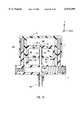
- FIG. 1is an exploded isometric view of one embodiment of a fetal vacuum extractor according to the invention.
- FIG. 2Ais an isometric view of the handle of FIG. 1.
- FIG. 2Bis an isometric sectional view of the handle of FIG. 2A along cutting plane A--A of FIG. 2A.
- FIG. 3Ais an isometric view of the palm chamber of FIG. 1.
- FIG. 3Bis an isometric sectional view of the palm chamber of FIG. 3A along cutting plane B--B of FIG. 3A.
- FIG. 4is a cross sectional diagram the vacuum cup of FIG. 1 along cutting plane C--C of FIG. 1.
- FIG. 5Ais an isometric view of the fetal vacuum extractor of FIG. 1 in its assembled, uncompressed position.
- FIG. 5Bis an isometric view of the fetal vacuum extractor of FIG. 1 in its assembled, compressed position.
- FIG. 6is an isometric view of another embodiment of the fetal vacuum extractor according to the invention.
- FIG. 7Ashows a vacuum indicator bellows in a contracted state.
- FIG. 7Bshows the vacuum indicator bellows in an expanded state.
- FIG. 8shows a proportionally correct drawing of the vacuum cup of FIG. 4 with descriptive dimensions shown.
- FIG. 9shows the vacuum cup of FIG. 8 during operation when a vacuum is applied within the cup chamber.
- FIG. 10shows a portion of an extractor which uses four one-way valves instead of two.
- the present inventionincludes a hand-held fetal vacuum extractor and method that has a cup which attaches to the fetal head, a handle connected to the cup for applying traction to the fetus, and a vacuum pump built into the handle.
- the fetal vacuum extractorcombines the handle and vacuum pump into a single hand-held unit.
- a vacuum indicator and vacuum release mechanismmay also be integrated into the hand-held fetal vacuum extractor. This enables a single operator to apply traction and adjust the vacuum in the cup using a single hand. The other hand is left free to perform other essential functions (e.g., guiding the fetal head, or suctioning the fetal nose and mouth).
- the vacuum indicatormay be positioned to be visible to the single operator to give the operator guidance in adjusting the vacuum in the cup in a timely manner.
- FIG. 1is an exploded isometric view of a fetal vacuum extractor 100 according to the invention.
- Extractor 100includes five general components: a handle 1, a vacuum pump 120, a vacuum release 130, a vacuum indicator 140, and a vacuum cup 150.
- the pumping action of the extractor 100is caused by the relative movement between handle 1 and palm chamber 2 (or vacuum pump 120).
- FIG. 2Ais an isometric view of handle 1.
- Handle 1may be machined or molded and may be composed of polycarbonate or some other plastic.
- Handle 1includes a main grip 202 having a grip surface 204 and a vacuum indicator window 206.
- a piston 208is part of vacuum pump 120 but is rigidly connected to handle 1.
- Piston 208extends up from main grip 202 and is supported by side supports 210 and 212 and central support 214.
- Two spring guide columns 216a and 216balso extend up from main grip 202.
- a cup connector 220extends down from main grip 202.
- Piston 208has a top vacuum chamber surface 234 that defines upper flap recess 222a for receiving a one-way vacuum flap valve 8a (FIG. 1) composed of, for example, silicone.
- FIG. 1is an isometric view of handle 1.
- Handle 1may be machined or molded and may be composed of polycarbonate or some other plastic.
- Handle 1includes a main grip
- FIG. 2Bis an isometric cross sectional view of handle 1 along cutting plane A--A of FIG. 2A.
- FIG. 2Bshows a lower flap recess 222b provided in a lower surface 238 of piston 208 for receiving a one-way exhaust flap valve 8b (FIG. 1) composed of, for example, silicone.
- Main grip 202is hollow having an inner surface 226 that defines a grip chamber 228.
- the grip chamber 228is substantially sealed from atmosphere during operation as described in detail below.
- Central support 214is hollow having an internal vacuum source channel 230 connecting grip chamber 228 to a hole 232 at the top chamber surface 234 of piston 208.
- Cup connector 220is also hollow having an internal channel 236 having a top end coupled to grip chamber 228.
- Palm chamber 2(part of vacuum pump 120) may be machined and/or molded, and may be composed of polyethylene or similar plastics. Palm chamber 2 is disposed over piston 208 and is described with reference to FIG. 3A and FIG. 3B.
- FIG. 3Ais an isometric view of palm chamber 2 that is one integrated body having an upper activation surface 302 and a side surface 304.
- FIG. 3Bis an isometric sectional view of palm chamber 2 along cutting plane B--B of FIG. 3A.
- FIG. 3Bshows that palm chamber 2 has an inner chamber surface 306 that, together with vacuum o-ring 9 (FIG. 1) and top chamber surface 234 of piston 208, defines a vacuum chamber 308.
- Fluidmay be vacuumed from internal vacuum source channel 230 into vacuum chamber 308 through one-way vacuum flap valve 8a provided in vacuum flap recess 222a. Fluid may be exhausted from vacuum chamber 308 through one-way exhaust flap valve 8b provided in exhaust flap recess 222b.
- Palm chamber 2also has inner guide surface 310a (and 310b) which defines a large diameter bore 312a (and 312b) and a small diameter bore 314a (and 314b). In its assembled, uncompressed position, compression springs 12a and 12b are received into respective large diameter bores 312a and 312b, but are not received into small diameter bores 314a and 314b.
- vacuum pump 120includes compression springs 12a and 12b (composed of, for example, stainless steel) which are fitted over respective spring guide columns 216a and 216b. Vacuum and exhaust flap valves 8a and 8b are fitted into the respective upper and lower recesses 222a and 222b. Vacuum and exhaust retaining rings 6a and 6b (composed of, for example, nylon or polycarbonate) are fitted into respective flap recesses 222a and 222b over respective flap valves 8a and 8b. A vacuum o-ring 9 (composed of, for example, silicone) is positioned along an outer periphery surface of piston 208 within groove 252 (FIG. 2A).
- the fingers of the operating handare placed around main grip 202 while placing the palm of the operating hand is pressed against the activation surface 302 of the palm chamber 2.
- the operatorsqueezes the fingers towards the palm, thereby overcoming the bias of compression springs 12a and 12b towards the uncompressed position.
- palm chamber 2is pressed towards handle 1.
- the movement of piston 208 relative to palm chamber 2forces piston 208 into vacuum chamber 308 and decreases the volume of vacuum chamber 308.
- the pressure within vacuum chamber 308increases above the ambient pressure just enough to open the one-way exhaust flap valve 8b to exhaust the fluid from vacuum chamber 308 as palm chamber 2 is compressed. During compression, the pressure within vacuum chamber 308 only slightly rises above the ambient pressure enough to keep the one-way exhaust flap valve 8b open. Essentially, the pressure within vacuum chamber 308 is at ambient pressure during compression of palm chamber 2.
- the distance between activation surface 302 of palm chamber 2 and grip surface 204 of main grip 202is approximately two inches, but may vary from a half inch or less to four inches or more.
- Vacuum release 130is now described with reference to FIG. 1.
- a vacuum release 130is provided in one longitudinal end 242 of main grip 202 to cap one end of grip chamber 228.
- Vacuum release 130includes a release valve 11 (composed of, for example, polyester, PVC, and/or stainless steel) which is first inserted into the end 242 of main grip 202.
- Release valve 11may be, for example, part number BK333303S supplied by Bestak of Norfork, England.
- Vacuum release 130also includes a release button 5 (composed of, for example, polycarbonate) which is inserted into the end of main grip over release valve 11. When release button 5 is pressed by, for example, the operator's thumb, fluid within grip chamber 228 communicates with the ambient environment through release value 11. If there is a vacuum within grip chamber 302 with respect to the ambient pressure, the vacuum is released when release button 5 is pressed.
- Vacuum indicator 140is now described with reference to FIG. 1.
- a vacuum indicator 140is provided in the other longitudinal end 244 of main grip 202 and caps the other longitudinal end of grip chamber 228.
- the vacuum indicator 140includes a gauge spring 13, a gauge ring 4 (composed of, for example, polycarbonate) and a gauge o-ring 10 (composed of, for example, silicone).
- the gauge o-ring 10is provided within a groove along the outer circumference of gauge ring 4 so that gauge ring 4 acts as a seal between grip chamber 228 and the ambient environment.
- Gauge ring 4is free to slide along a longitudinal direction (i.e., parallel to the x-axis) within grip chamber 228 in response to pressure differences between grip chamber 228 and the ambient pressure.
- Gauge ring 4compresses gauge spring 13 substantially proportional to the vacuum level within grip chamber 228.
- a scaleis provided on main grip 202 which correlates the position of the gauge ring 4 with the pressure within grip chamber 228. For example, the position of gauge ring 4 at a vacuum of 58 centimeters of mercury is marked on the scale with "58".
- vacuum indicator 140may be composed of a bellows 700 (FIG. 7A and FIG. 7B) having an open end 702 and a sealed end 704. Open end 702 is seated over bellows attachment 256 (FIG. 2B). Bellows 700 expands (and contracts) in response to a weaker (and stronger) vacuum within grip chamber 228. Therefore, the position of a given part of bellows 700 (e.g., sealed end 704) is an indicator of the vacuum within grip chamber 228.
- FIG. 7Ashows bellows 700 in a contracted state while FIG. 7B shows bellows 700 in an expanded state.
- Vacuum release 130 and vacuum indicator 140cap both ends 242 and 244 of grip chamber 228 so that when vacuum release 130 is not activated and vacuum flap valve 8a is closed, the grip chamber 308 and vacuum source channel 230 combination are sealed off except through channel 236.
- FIG. 4shows that vacuum cup 150 includes a cup 3 that is shown along cutting plane C--C of FIG. 1.
- Cup 3may be molded or vacuum formed and is composed of a flexible material such as silicone, Kraton, or polyethylene.
- Cup 3is semi-rigid and includes a hollow shaft 402 having an inner wall 404 defining a cup channel 406.
- "Semi-rigid"is defined as "able to hold its shape and yet may be capable of flexing.”
- Hollow shaft 402may be approximately five inches long, but may range from three inches long or less to seven inches long or more depending on the preference of the primary operator, the type of birth opening (e.g., Cesarean incision), and the anatomy of the mother.
- One end 408 of shaft 402is tightly connected to channel 236 of handle 1 so that grip chamber 228 is fluidly coupled to cup channel 406.
- Vacuum cup 150also includes a flexible cup portion 410 having an inner wall 412 to define a cup chamber 414.
- Cup chamber 414is fluidly coupled to cup channel 406 at an apex 418.
- Cup portion 410has a lip 416 that contacts the work piece (e.g., fetal head H).
- FIG. 8shows a drawing of the vacuum cup 150 cross section of FIG. 4 with descriptive dimensions.
- Cup portion 410has annular ridges 420 circumscribing inner walls 412.
- Cup portion 410has substantially more flexible walls compared to the cups of the prior art. This flexibility is caused by a combination of two factors: the thickness of the walls 425 of cup portion 410 and the elasticity of the materials composing the walls.
- the thickness of a ridge region 430 (defined as the region proximate to ridges 420) of walls 425ranges from 0.010 inches to 0.025 inches or from 0.010 inches to 0.050 inches.
- the wall thicknessmay have a minimum of 0.025 to 0.050 inches and a maximum thickness of from 0.100 to 0.300 inches. This assumes a material having a durometer measurement (an elasticity measurement) of from shore A 20 durometers to shore A 80 durometers.
- the materialmay be in the range of shore A 50 to shore A 60 durometers and may be approximately shore A 55 durometers. Such elasticity may be obtained from kraton and silicone. However, more rigid materials may be used if the wall 425 thickness is less. For example, a material twice as rigid will require wall half as thick as those described above.
- FIG. 9illustrates vacuum cup 150 during operation when a vacuum is applied within cup chamber 414.
- cup portion 410is slightly compressed onto the fetal head only enough to create a seal between the cup portion 410 and the fetal head H.
- a vacuumis then applied within cup chamber 414.
- the vacuumcauses urges lip 416 to stretch over the fetal head as the volume within cup chamber 414 decreases, thereby increasing the surface area of the fetal head H exposed to the vacuum.
- ridges 420are also brought in contact with the fetal head H, thereby improving the seal between the fetal head H and cup portion 410.
- the stretching of lip 416causes the diameter of the cup chamber 404 at the fetal head to be increased from approximately 2.54 inches to at least approximately 2.80 inches (at least 10%). During operation, this diameter may even increase by 20 to 40% or more.
- cup portion 410has relatively flexible walls, the cup portion 410 does not collapse under a strong vacuum because a portion of the fetal head H is suctioned into cup chamber 414 and supports inner wall 412. The fetal head H is temporarily deformed causing a caput (i.e., a knob-like protrusion) as a portion of the fetal head H is suctioned into the cup chamber 414.
- a caputi.e., a knob-like protrusion
- cup chamber 414during operation, is smaller in size than the cup chamber of the prior art, the deformation of the fetal head H is substantially reduced.
- Filter 15(FIG. 1), composed of, for example, a polyester or polyurethane foam, is inserted into cup 3 and adhered to cup 3 with an adhesive. Filter 15 substantially prevents bodily liquids and debris (e.g., vernix, mucus) from entering into handle 1 and palm chamber 2 and interfering with the operation of extractor 100.
- bodily liquids and debrise.g., vernix, mucus
- a method of operating extractor 100is described. First, lip 416 of cup portion 410 is attached to a fetal head to define chamber 414.
- the operating handis positioned around handle 1 and palm chamber 2 as described above.
- a vacuumis asserted within chamber 414 by repeating clinching and releasing the operating hand until the desired vacuum is attained.
- the operatorpulls on handle 1 to draw the fetus through the birth canal. If the vacuum is too high or the mother is between contractions, the vacuum is reduced with vacuum release 130. This whole time, the primary operator can determine the level of vacuum by monitoring vacuum indicator 140.
- the abovedescribes a fetal vacuum extractor 100 having a 50 to 75 percent reduction in the sealed off fluid volume compared to the prior art.
- the "sealed off fluid volume”is defined as "the volume of the fluid to which the vacuum is applied in the extractor.” This reduction is due, in part, to the elimination of flexible tubing that is required in the prior art to coupled the remote vacuum pump to the extractor handle. The reduction is also due, in part, to filter 15 occupying volume within cup chamber 414. Furthermore, a single operator can both provide the vacuum and pull on the handle 110 using a single hand. This represents substantial improvements in the art of fetal vacuum extractors.
- FIG. 6is an isometric view of a fetal vacuum extractor 600 according to another embodiment of the invention. Extractor 600 is structured similarly to extractor 100 except that palm chamber 2 is integrated with handle 1 and is electronically operated rather than manually operated.
- Activation surface 302is a surface of a button 6.
- Electric pump 610is provided within palm chamber 2, and is activated by pressing a palm or other surface against button 6 to close an electric circuit.
- Electric pump 610may be, for example, one of the pumps from the PIAB mini vacuum series which is supplied by PIAB, 65 Sharp Street, Hingham, Mass., 02043.
- Electric pump 610is coupled, through cup channel 406, to cup chamber 414 to provide a vacuum in cup chamber 414.
- the electric pumpmay be powered by batteries 620 or by an external electricity source such as a plug 630 connected to an outlet 640.
- valves 8a and 8bare described as being flap valves, valves 8a and 8b may be other types of one-way valves such as a duck bill valve, or a ball valve that has a ball sliding within a seating.
- FIG. 10shows a portion of an extractor 900 which is structured similarly to extractor 100 except as follows.
- Extractor 900has a secondary vacuum chamber 930 which is defined by inner chamber surface 306, lower surface 238 of piston 208, a lower wall 910 connected to inner chamber surface around central support 214, and an o-ring 940.
- Valve 8bis provided on through the top of palm chamber 2.
- vacuum indicator 140is describes as being composed of a spring loaded o-ring seal or a bellows, other vacuum indicators will suffice such as a vacuum chamber vacuum indicator.
- vacuum cup 3may be disposable or the entire extractor 100 may be disposable.
- palm chamber 2 and handle 1 of extractor 600may be reusable.
Landscapes
- Health & Medical Sciences (AREA)
- Surgery (AREA)
- Gynecology & Obstetrics (AREA)
- Life Sciences & Earth Sciences (AREA)
- Medical Informatics (AREA)
- General Health & Medical Sciences (AREA)
- Reproductive Health (AREA)
- Engineering & Computer Science (AREA)
- Biomedical Technology (AREA)
- Heart & Thoracic Surgery (AREA)
- Pregnancy & Childbirth (AREA)
- Molecular Biology (AREA)
- Animal Behavior & Ethology (AREA)
- Nuclear Medicine, Radiotherapy & Molecular Imaging (AREA)
- Public Health (AREA)
- Veterinary Medicine (AREA)
- External Artificial Organs (AREA)
- Surgical Instruments (AREA)
- Jet Pumps And Other Pumps (AREA)
- Medicines Containing Plant Substances (AREA)
- Vaporization, Distillation, Condensation, Sublimation, And Cold Traps (AREA)
Abstract
Description
Claims (35)
Priority Applications (11)
| Application Number | Priority Date | Filing Date | Title |
|---|---|---|---|
| US09/075,448US6074399A (en) | 1998-05-08 | 1998-05-08 | Hand-held fetal vacuum extractor having an integrated pump and handle |
| US09/203,003US6059795A (en) | 1998-05-08 | 1998-11-30 | Maneuverable fetal vacuum extraction for use with malpresenting fetus |
| DE69935324TDE69935324D1 (en) | 1998-05-08 | 1999-05-06 | MANUAL OBSTETRIC VACUUM EXTRACTOR WITH INTEGRATED PUMP AND HANDLE |
| CA002330582ACA2330582C (en) | 1998-05-08 | 1999-05-06 | Hand-held fetal vacuum extractor having an integrated pump and handle |
| AT99922866TATE355024T1 (en) | 1998-05-08 | 1999-05-06 | MANUAL OBSTETRIC VACUUM EXTRACTOR WITH INTEGRATED PUMP AND HANDLE |
| AU39767/99AAU762627B2 (en) | 1998-05-08 | 1999-05-06 | Hand-held fetal vacuum extractor having an integrated pump and handle |
| NZ507884ANZ507884A (en) | 1998-05-08 | 1999-05-06 | Hand-held fetal vacuum extractor having an integrated pump and handle such that a single human hand can grasp both the grip surface and the activation surface simultaneously |
| PCT/US1999/010084WO1999058071A1 (en) | 1998-05-08 | 1999-05-06 | Hand-held fetal vacuum extractor having an integrated pump and handle |
| EP99922866AEP1079748B1 (en) | 1998-05-08 | 1999-05-06 | Hand-held fetal vacuum extractor having an integrated pump and handle |
| PT99922866TPT1079748E (en) | 1998-05-08 | 1999-05-06 | Hand-held fetal vacuum extractor having an integrated pump and handle |
| US09/365,658US6355047B1 (en) | 1998-05-08 | 1999-08-02 | Traction force sensing vacuum extractor |
Applications Claiming Priority (1)
| Application Number | Priority Date | Filing Date | Title |
|---|---|---|---|
| US09/075,448US6074399A (en) | 1998-05-08 | 1998-05-08 | Hand-held fetal vacuum extractor having an integrated pump and handle |
Related Child Applications (1)
| Application Number | Title | Priority Date | Filing Date |
|---|---|---|---|
| US09/203,003Continuation-In-PartUS6059795A (en) | 1998-05-08 | 1998-11-30 | Maneuverable fetal vacuum extraction for use with malpresenting fetus |
Publications (1)
| Publication Number | Publication Date |
|---|---|
| US6074399Atrue US6074399A (en) | 2000-06-13 |
Family
ID=22125829
Family Applications (1)
| Application Number | Title | Priority Date | Filing Date |
|---|---|---|---|
| US09/075,448Expired - LifetimeUS6074399A (en) | 1998-05-08 | 1998-05-08 | Hand-held fetal vacuum extractor having an integrated pump and handle |
Country Status (9)
| Country | Link |
|---|---|
| US (1) | US6074399A (en) |
| EP (1) | EP1079748B1 (en) |
| AT (1) | ATE355024T1 (en) |
| AU (1) | AU762627B2 (en) |
| CA (1) | CA2330582C (en) |
| DE (1) | DE69935324D1 (en) |
| NZ (1) | NZ507884A (en) |
| PT (1) | PT1079748E (en) |
| WO (1) | WO1999058071A1 (en) |
Cited By (41)
| Publication number | Priority date | Publication date | Assignee | Title |
|---|---|---|---|---|
| US20020065519A1 (en)* | 2000-11-30 | 2002-05-30 | Vines Victor L. | Vacuum extraction monitoring |
| US6468284B1 (en)* | 2001-05-04 | 2002-10-22 | Clinical Innovation Associates, Inc. | Method and apparatus for vaccum assisted fetal extraction |
| WO2002088546A1 (en) | 2001-04-27 | 2002-11-07 | Prism Enterprises, Lp | Obstetrical vacuum extractor cup and pump |
| US6641575B1 (en)* | 1999-01-26 | 2003-11-04 | Neal M. Lonky | Surgical vacuum instrument for retracting, extracting, and manipulating tissue |
| US20040002630A1 (en)* | 2002-06-28 | 2004-01-01 | Wu Steven Zung-Hong | Suction device for surgical applications |
| US20040010266A1 (en)* | 2000-11-30 | 2004-01-15 | Vines Victor L. | Vacuum extraction monitoring with existing fetal heart rate monitors |
| US20040199356A1 (en)* | 2000-11-30 | 2004-10-07 | Vines Victor L. | Wireless vacuum extraction monitoring |
| US20050015098A1 (en)* | 2003-07-14 | 2005-01-20 | Vines Victor L. | Vacuum extraction business method |
| US20050203334A1 (en)* | 1999-01-26 | 2005-09-15 | Lonky Neal M. | Vacuum instrument for laparotomy procedures |
| WO2006027731A1 (en)* | 2004-09-09 | 2006-03-16 | Lina Medical Aps | An obstetrical vacuum cup |
| US20080272023A1 (en)* | 2007-04-20 | 2008-11-06 | Mccormick Matthew | Surgical Pack and Tray |
| US20080281254A1 (en)* | 2007-04-20 | 2008-11-13 | Mark Humayun | Independent Surgical Center |
| US20080281301A1 (en)* | 2007-04-20 | 2008-11-13 | Deboer Charles | Personal Surgical Center |
| US20090143734A1 (en)* | 2007-04-20 | 2009-06-04 | Mark Humayun | Sterile surgical tray |
| US20090254096A1 (en)* | 2007-11-08 | 2009-10-08 | Association For Public Health Services | Vacuum delivery extractor |
| US20100174415A1 (en)* | 2007-04-20 | 2010-07-08 | Mark Humayun | Sterile surgical tray |
| US20100185048A1 (en)* | 2009-01-22 | 2010-07-22 | Neal Marc Lonky | Portable regulated vacuum pump for medical procedures |
| US20100318096A1 (en)* | 2008-02-13 | 2010-12-16 | Michael G. Ross | Obstetrical vacuum extractor with over-traction release |
| RU2470583C2 (en)* | 2011-03-24 | 2012-12-27 | Василий Васильевич Власюк | Method of determining localisation of leading point of head by changes of skull in dead fetuses and newborns |
| US8568391B2 (en) | 2007-04-20 | 2013-10-29 | Doheny Eye Institute | Sterile surgical tray |
| US20130289577A1 (en)* | 2011-12-23 | 2013-10-31 | Leah BERHANE | Scapuloblade Shoulder Dystocia Device |
| US20130296902A1 (en)* | 2010-09-20 | 2013-11-07 | Britamed Incorporated | Vacuum anchoring catheter |
| US20130304081A1 (en)* | 2010-09-30 | 2013-11-14 | Monty Medical Limited | Obstetric vacuum extractor |
| US8915894B1 (en) | 2000-01-24 | 2014-12-23 | Meditech Development Incorporated | Vacuum cup for delivery of agents during vacuum treatment |
| US9186444B2 (en) | 2012-05-07 | 2015-11-17 | Meditech Development Incorporated | Portable regulated pressure devices for medical procedures |
| WO2016032394A1 (en)* | 2014-08-27 | 2016-03-03 | Becton Dickinson Holdings Pte Ltd | An apparatus for extraction of at least one element from a cavity and a pressure limitation apparatus |
| WO2017054059A1 (en)* | 2015-10-01 | 2017-04-06 | Teoh Pek Joo | Obstetrical vacuum apparatus |
| US9962226B2 (en) | 2013-11-28 | 2018-05-08 | Alcon Pharmaceuticals Ltd. | Ophthalmic surgical systems, methods, and devices |
| US10363380B2 (en) | 2016-05-20 | 2019-07-30 | Lapovations, LLC | Device and methods for lifting patient tissue during laparoscopic surgery |
| USD858743S1 (en)* | 2017-10-13 | 2019-09-03 | JCT Solutions Pty Ltd | Obstetrical vacuum apparatus |
| USD858742S1 (en)* | 2017-10-13 | 2019-09-03 | JCT Solutions Pty Ltd | Obstetrical vacuum apparatus |
| USD859635S1 (en)* | 2017-10-13 | 2019-09-10 | JCT Solutions Pty Ltd | Obstetrical vacuum apparatus |
| WO2020011616A1 (en)* | 2018-07-10 | 2020-01-16 | Bayer Oy | A vacuum-based tenaculum |
| US10537472B2 (en) | 2013-11-28 | 2020-01-21 | Alcon Pharmaceuticals Ltd. | Ophthalmic surgical systems, methods, and devices |
| CN113208711A (en)* | 2021-06-07 | 2021-08-06 | 徐州华德康复医学研究院有限公司 | Vacuum suction device for fetal head |
| US11344287B2 (en)* | 2017-12-11 | 2022-05-31 | Lapovations, LLC | Laparoscopic surgical instrument |
| US11504260B2 (en) | 2018-10-04 | 2022-11-22 | Lipocosm, Llc | Rigidifying brace |
| US11540894B2 (en) | 2018-10-04 | 2023-01-03 | Lipocosm, Llc | Rigiditying brace |
| US11547155B2 (en)* | 2020-12-07 | 2023-01-10 | Lipocosm, Llc | External vacuum expander with non-adhesive rim |
| US12042458B2 (en) | 2020-12-07 | 2024-07-23 | Lipocosm, Llc | External vacuum tissue expander with slidable rim |
| US12121077B2 (en) | 2018-10-04 | 2024-10-22 | Lipocosm, Llc | Brassiere with rigidifying cups |
Families Citing this family (3)
| Publication number | Priority date | Publication date | Assignee | Title |
|---|---|---|---|---|
| AU5788100A (en)* | 1999-07-09 | 2001-01-30 | Prism Enterprises, Inc. | Obstetrical vacuum extractor cup |
| GB0416172D0 (en) | 2004-07-20 | 2004-08-18 | George Samuel | Variable size obstetric suction cup (Vontouse) |
| WO2025062006A1 (en) | 2023-09-22 | 2025-03-27 | Layco Ip B.V. | Re-usable obstetrical vacuum extractor |
Citations (16)
| Publication number | Priority date | Publication date | Assignee | Title |
|---|---|---|---|---|
| US2194989A (en)* | 1937-07-07 | 1940-03-26 | Torpin Richard | Obstetrical device |
| US2702038A (en)* | 1953-03-23 | 1955-02-15 | Uddenberg Goran Olof | Releasing apparatus for childbirths |
| US2917050A (en)* | 1958-11-28 | 1959-12-15 | Arthur D Kenyon | Means and method for assisting the birth of a child |
| DE1123432B (en)* | 1960-09-14 | 1962-02-08 | Dr Med Kurt Sokol | Device for vacuum extraction during childbirth |
| US3202152A (en)* | 1963-03-08 | 1965-08-24 | John F Wood | Vacuum extractor for childbirth |
| US3207160A (en)* | 1963-11-05 | 1965-09-21 | Ockert S Heyns | Apparatus for facilitating the processes of parturition |
| US3612722A (en)* | 1969-03-03 | 1971-10-12 | Theodore C Neward | Hand vacuum pump |
| US3765408A (en)* | 1972-03-16 | 1973-10-16 | Kawai Tosando Kk | Soft obstetric vacuum cup for assisting childbirth |
| US3782385A (en)* | 1972-10-24 | 1974-01-01 | P Loyd | Breast pump |
| US3794044A (en)* | 1971-10-20 | 1974-02-26 | Ethyl Corp | Delivery forceps |
| DE3138589A1 (en)* | 1981-09-29 | 1983-04-07 | Atmos Fritzsching & Co Gmbh, Zweigniederlassung Lenzkirch Im Schwarzwald, 7825 Lenzkirch | Device for vacuum extraction |
| WO1989006112A1 (en)* | 1987-12-29 | 1989-07-13 | Menox Ab | Obstetric suction device |
| US5019086A (en)* | 1989-09-12 | 1991-05-28 | Neward Theodore C | Manipulable vacuum extractor for childbirth and method of using the same |
| US5071403A (en)* | 1989-11-14 | 1991-12-10 | Isg/Ag | Method and apparatus for protecting the pump of a breast pump from fouling by milk |
| US5224947A (en)* | 1991-10-21 | 1993-07-06 | Cooper Richard N | Soft, readily expandable vacuum bell assembly |
| US5281229A (en)* | 1991-08-09 | 1994-01-25 | Neward Theodore C | Obstetrical vacuum extractor |
Family Cites Families (2)
| Publication number | Priority date | Publication date | Assignee | Title |
|---|---|---|---|---|
| US5277557A (en)* | 1993-01-11 | 1994-01-11 | Cooper Richard N | Hand-held and hand-operated vacuum pump |
| US5395379A (en)* | 1993-07-22 | 1995-03-07 | Deutchman; Mark E. | Extractor for childbirth and aspirator/injector device |
- 1998
- 1998-05-08USUS09/075,448patent/US6074399A/ennot_activeExpired - Lifetime
- 1999
- 1999-05-06EPEP99922866Apatent/EP1079748B1/ennot_activeExpired - Lifetime
- 1999-05-06NZNZ507884Apatent/NZ507884A/ennot_activeIP Right Cessation
- 1999-05-06CACA002330582Apatent/CA2330582C/ennot_activeExpired - Fee Related
- 1999-05-06ATAT99922866Tpatent/ATE355024T1/ennot_activeIP Right Cessation
- 1999-05-06AUAU39767/99Apatent/AU762627B2/ennot_activeExpired
- 1999-05-06PTPT99922866Tpatent/PT1079748E/enunknown
- 1999-05-06WOPCT/US1999/010084patent/WO1999058071A1/enactiveIP Right Grant
- 1999-05-06DEDE69935324Tpatent/DE69935324D1/ennot_activeExpired - Lifetime
Patent Citations (16)
| Publication number | Priority date | Publication date | Assignee | Title |
|---|---|---|---|---|
| US2194989A (en)* | 1937-07-07 | 1940-03-26 | Torpin Richard | Obstetrical device |
| US2702038A (en)* | 1953-03-23 | 1955-02-15 | Uddenberg Goran Olof | Releasing apparatus for childbirths |
| US2917050A (en)* | 1958-11-28 | 1959-12-15 | Arthur D Kenyon | Means and method for assisting the birth of a child |
| DE1123432B (en)* | 1960-09-14 | 1962-02-08 | Dr Med Kurt Sokol | Device for vacuum extraction during childbirth |
| US3202152A (en)* | 1963-03-08 | 1965-08-24 | John F Wood | Vacuum extractor for childbirth |
| US3207160A (en)* | 1963-11-05 | 1965-09-21 | Ockert S Heyns | Apparatus for facilitating the processes of parturition |
| US3612722A (en)* | 1969-03-03 | 1971-10-12 | Theodore C Neward | Hand vacuum pump |
| US3794044A (en)* | 1971-10-20 | 1974-02-26 | Ethyl Corp | Delivery forceps |
| US3765408A (en)* | 1972-03-16 | 1973-10-16 | Kawai Tosando Kk | Soft obstetric vacuum cup for assisting childbirth |
| US3782385A (en)* | 1972-10-24 | 1974-01-01 | P Loyd | Breast pump |
| DE3138589A1 (en)* | 1981-09-29 | 1983-04-07 | Atmos Fritzsching & Co Gmbh, Zweigniederlassung Lenzkirch Im Schwarzwald, 7825 Lenzkirch | Device for vacuum extraction |
| WO1989006112A1 (en)* | 1987-12-29 | 1989-07-13 | Menox Ab | Obstetric suction device |
| US5019086A (en)* | 1989-09-12 | 1991-05-28 | Neward Theodore C | Manipulable vacuum extractor for childbirth and method of using the same |
| US5071403A (en)* | 1989-11-14 | 1991-12-10 | Isg/Ag | Method and apparatus for protecting the pump of a breast pump from fouling by milk |
| US5281229A (en)* | 1991-08-09 | 1994-01-25 | Neward Theodore C | Obstetrical vacuum extractor |
| US5224947A (en)* | 1991-10-21 | 1993-07-06 | Cooper Richard N | Soft, readily expandable vacuum bell assembly |
Non-Patent Citations (7)
| Title |
|---|
| Arvind S. Moolgaoker, MD, SYED O.S. Ahamed, and Peter R. Payne, A Comparison of Different Methods of Instrumental Delivery Based on Electronic Measurements of Compression and Traction, Feb. 19, 1979, pp. 1 4.* |
| Arvind S. Moolgaoker, MD, SYED O.S. Ahamed, and Peter R. Payne, A Comparison of Different Methods of Instrumental Delivery Based on Electronic Measurements of Compression and Traction, Feb. 19, 1979, pp. 1-4. |
| Chapter 9, Vacuum Delivery, Operative Obstetrics, pp. 173 189.* |
| Chapter 9, Vacuum Delivery, Operative Obstetrics, pp. 173-189. |
| CMI Obstetrical Vacuum Delivery Kit product information, Aug. 1995, Redmond, Oregon, 34 pages.* |
| Handbook of Vacuum Extraction in Obstetric Practice, Aldo Vacca, pp. 55 62.* |
| Handbook of Vacuum Extraction in Obstetric Practice, Aldo Vacca, pp. 55-62. |
Cited By (73)
| Publication number | Priority date | Publication date | Assignee | Title |
|---|---|---|---|---|
| US7935094B2 (en) | 1999-01-26 | 2011-05-03 | Meditech Development Incorporated | Vacuum instrument for slowing or arresting the flow of blood |
| US20110172569A1 (en)* | 1999-01-26 | 2011-07-14 | Meditech Development Incorporated | Vacuum instrument for slowing or arresting the flow of blood |
| US6641575B1 (en)* | 1999-01-26 | 2003-11-04 | Neal M. Lonky | Surgical vacuum instrument for retracting, extracting, and manipulating tissue |
| US8608714B2 (en) | 1999-01-26 | 2013-12-17 | Meditech Development Incorporated | Vacuum instrument for slowing or arresting the flow of blood |
| US20050203334A1 (en)* | 1999-01-26 | 2005-09-15 | Lonky Neal M. | Vacuum instrument for laparotomy procedures |
| US20040138645A1 (en)* | 1999-01-26 | 2004-07-15 | Lonky Neal M. | Vacuum instrument for slowing or arresting the flow of blood |
| US9138216B2 (en) | 2000-01-24 | 2015-09-22 | Meditech Development Incorporated | Portable regulated vacuum pump for medical procedures |
| US8915894B1 (en) | 2000-01-24 | 2014-12-23 | Meditech Development Incorporated | Vacuum cup for delivery of agents during vacuum treatment |
| US20040199356A1 (en)* | 2000-11-30 | 2004-10-07 | Vines Victor L. | Wireless vacuum extraction monitoring |
| US20020065519A1 (en)* | 2000-11-30 | 2002-05-30 | Vines Victor L. | Vacuum extraction monitoring |
| US6872212B2 (en) | 2000-11-30 | 2005-03-29 | Victor L. Vines | Vacuum extraction monitor with attachment for hand pump |
| US20050101969A1 (en)* | 2000-11-30 | 2005-05-12 | Vines Victor L. | Vacuum extraction monitoring |
| US6901345B1 (en) | 2000-11-30 | 2005-05-31 | Victor L. Vines | Vacuum extraction monitor for electric pump |
| US20040010266A1 (en)* | 2000-11-30 | 2004-01-15 | Vines Victor L. | Vacuum extraction monitoring with existing fetal heart rate monitors |
| US7069170B2 (en) | 2000-11-30 | 2006-06-27 | Vines Victor L | Wireless vacuum extraction monitoring |
| US6620171B2 (en)* | 2000-11-30 | 2003-09-16 | Victor L. Vines | Vacuum extraction monitoring |
| WO2002088546A1 (en) | 2001-04-27 | 2002-11-07 | Prism Enterprises, Lp | Obstetrical vacuum extractor cup and pump |
| US6468284B1 (en)* | 2001-05-04 | 2002-10-22 | Clinical Innovation Associates, Inc. | Method and apparatus for vaccum assisted fetal extraction |
| US20040002630A1 (en)* | 2002-06-28 | 2004-01-01 | Wu Steven Zung-Hong | Suction device for surgical applications |
| US20050015098A1 (en)* | 2003-07-14 | 2005-01-20 | Vines Victor L. | Vacuum extraction business method |
| US20070198027A1 (en)* | 2004-09-09 | 2007-08-23 | Morch Jacob Sebastian L | Obstetrical vacuum cup |
| WO2006027731A1 (en)* | 2004-09-09 | 2006-03-16 | Lina Medical Aps | An obstetrical vacuum cup |
| US9730833B2 (en) | 2007-04-20 | 2017-08-15 | Doheny Eye Institute | Independent surgical center |
| US8177776B2 (en) | 2007-04-20 | 2012-05-15 | Doheny Eye Institute | Independent surgical center |
| US20090143734A1 (en)* | 2007-04-20 | 2009-06-04 | Mark Humayun | Sterile surgical tray |
| US20080281301A1 (en)* | 2007-04-20 | 2008-11-13 | Deboer Charles | Personal Surgical Center |
| US20080281254A1 (en)* | 2007-04-20 | 2008-11-13 | Mark Humayun | Independent Surgical Center |
| US20080272023A1 (en)* | 2007-04-20 | 2008-11-06 | Mccormick Matthew | Surgical Pack and Tray |
| US8177064B2 (en) | 2007-04-20 | 2012-05-15 | Doheny Eye Institute | Surgical pack and tray |
| US20100174415A1 (en)* | 2007-04-20 | 2010-07-08 | Mark Humayun | Sterile surgical tray |
| US8323271B2 (en) | 2007-04-20 | 2012-12-04 | Doheny Eye Institute | Sterile surgical tray |
| US10363165B2 (en) | 2007-04-20 | 2019-07-30 | Doheny Eye Institute | Independent surgical center |
| US9463070B2 (en) | 2007-04-20 | 2016-10-11 | Doheny Eye Institute | Sterile surgical tray |
| US8623000B2 (en) | 2007-04-20 | 2014-01-07 | Doheny Eye Institute | Independent surgical center |
| US8568391B2 (en) | 2007-04-20 | 2013-10-29 | Doheny Eye Institute | Sterile surgical tray |
| US10070934B2 (en) | 2007-04-20 | 2018-09-11 | Doheny Eye Institute | Sterile surgical tray |
| US9526580B2 (en) | 2007-04-20 | 2016-12-27 | Doheny Eye Institute | Sterile surgical tray |
| WO2009060431A3 (en)* | 2007-11-08 | 2010-03-11 | Association For Public Health Services | Vacuum delivery extractor |
| US20090254096A1 (en)* | 2007-11-08 | 2009-10-08 | Association For Public Health Services | Vacuum delivery extractor |
| US8361083B2 (en) | 2008-02-13 | 2013-01-29 | Michael G. Ross | Obstetrical vacuum extractor with over-traction release |
| US20100318096A1 (en)* | 2008-02-13 | 2010-12-16 | Michael G. Ross | Obstetrical vacuum extractor with over-traction release |
| US8409214B2 (en) | 2009-01-22 | 2013-04-02 | Meditech Development Incorporated | Portable regulated vacuum pump for medical procedures |
| US20100185048A1 (en)* | 2009-01-22 | 2010-07-22 | Neal Marc Lonky | Portable regulated vacuum pump for medical procedures |
| US20130296902A1 (en)* | 2010-09-20 | 2013-11-07 | Britamed Incorporated | Vacuum anchoring catheter |
| US20130304081A1 (en)* | 2010-09-30 | 2013-11-14 | Monty Medical Limited | Obstetric vacuum extractor |
| RU2470583C2 (en)* | 2011-03-24 | 2012-12-27 | Василий Васильевич Власюк | Method of determining localisation of leading point of head by changes of skull in dead fetuses and newborns |
| US20130289577A1 (en)* | 2011-12-23 | 2013-10-31 | Leah BERHANE | Scapuloblade Shoulder Dystocia Device |
| US9186444B2 (en) | 2012-05-07 | 2015-11-17 | Meditech Development Incorporated | Portable regulated pressure devices for medical procedures |
| US10987183B2 (en) | 2013-11-28 | 2021-04-27 | Alcon Inc. | Ophthalmic surgical systems, methods, and devices |
| US10537472B2 (en) | 2013-11-28 | 2020-01-21 | Alcon Pharmaceuticals Ltd. | Ophthalmic surgical systems, methods, and devices |
| US9962226B2 (en) | 2013-11-28 | 2018-05-08 | Alcon Pharmaceuticals Ltd. | Ophthalmic surgical systems, methods, and devices |
| US11097992B2 (en) | 2014-08-27 | 2021-08-24 | Becton Dickinson Holdings Pte Ltd | Apparatus for extraction of at least one element from a cavity and a pressure limitation apparatus |
| US11690650B2 (en) | 2014-08-27 | 2023-07-04 | Maternal Newborn Health Innovations, Pbc | Apparatus for extraction of at least one element from a cavity and a pressure limitation apparatus |
| CN107072694A (en)* | 2014-08-27 | 2017-08-18 | 贝克顿迪金森控股私人有限公司 | Device for removing at least one object from cavity and pressure limiting device |
| US11986217B2 (en) | 2014-08-27 | 2024-05-21 | Maternal Newborn Health Innovations, Pbc | Apparatus for extraction of at least one element from a cavity and a pressure limitation apparatus |
| WO2016032394A1 (en)* | 2014-08-27 | 2016-03-03 | Becton Dickinson Holdings Pte Ltd | An apparatus for extraction of at least one element from a cavity and a pressure limitation apparatus |
| WO2017054059A1 (en)* | 2015-10-01 | 2017-04-06 | Teoh Pek Joo | Obstetrical vacuum apparatus |
| US10363380B2 (en) | 2016-05-20 | 2019-07-30 | Lapovations, LLC | Device and methods for lifting patient tissue during laparoscopic surgery |
| USD858743S1 (en)* | 2017-10-13 | 2019-09-03 | JCT Solutions Pty Ltd | Obstetrical vacuum apparatus |
| USD858742S1 (en)* | 2017-10-13 | 2019-09-03 | JCT Solutions Pty Ltd | Obstetrical vacuum apparatus |
| USD859635S1 (en)* | 2017-10-13 | 2019-09-10 | JCT Solutions Pty Ltd | Obstetrical vacuum apparatus |
| US11344287B2 (en)* | 2017-12-11 | 2022-05-31 | Lapovations, LLC | Laparoscopic surgical instrument |
| WO2020011616A1 (en)* | 2018-07-10 | 2020-01-16 | Bayer Oy | A vacuum-based tenaculum |
| US11992429B2 (en) | 2018-10-04 | 2024-05-28 | Lipocosm, Llc | Rigidifying brace |
| US12004909B2 (en) | 2018-10-04 | 2024-06-11 | Lipocosm, Llc | Rigidifying brace |
| US11540894B2 (en) | 2018-10-04 | 2023-01-03 | Lipocosm, Llc | Rigiditying brace |
| US11504260B2 (en) | 2018-10-04 | 2022-11-22 | Lipocosm, Llc | Rigidifying brace |
| US12121077B2 (en) | 2018-10-04 | 2024-10-22 | Lipocosm, Llc | Brassiere with rigidifying cups |
| US11793245B2 (en)* | 2020-12-07 | 2023-10-24 | Lipocosm, Llc | Brassiere with slidable rims |
| US11547155B2 (en)* | 2020-12-07 | 2023-01-10 | Lipocosm, Llc | External vacuum expander with non-adhesive rim |
| US12042458B2 (en) | 2020-12-07 | 2024-07-23 | Lipocosm, Llc | External vacuum tissue expander with slidable rim |
| US12364293B2 (en) | 2020-12-07 | 2025-07-22 | Lipocosm, Llc | Brassiere with slidable rims |
| CN113208711A (en)* | 2021-06-07 | 2021-08-06 | 徐州华德康复医学研究院有限公司 | Vacuum suction device for fetal head |
Also Published As
| Publication number | Publication date |
|---|---|
| EP1079748A1 (en) | 2001-03-07 |
| PT1079748E (en) | 2007-05-31 |
| CA2330582A1 (en) | 1999-11-18 |
| NZ507884A (en) | 2004-11-26 |
| EP1079748A4 (en) | 2004-08-04 |
| AU3976799A (en) | 1999-11-29 |
| CA2330582C (en) | 2008-02-19 |
| WO1999058071A1 (en) | 1999-11-18 |
| AU762627B2 (en) | 2003-07-03 |
| DE69935324D1 (en) | 2007-04-12 |
| ATE355024T1 (en) | 2006-03-15 |
| EP1079748B1 (en) | 2007-02-28 |
Similar Documents
| Publication | Publication Date | Title |
|---|---|---|
| US6074399A (en) | Hand-held fetal vacuum extractor having an integrated pump and handle | |
| EP1152700B1 (en) | Maneuverable fetal vacuum extractor for use with malpresenting fetus | |
| US4643719A (en) | Manually operable aspirator | |
| US4430076A (en) | Combined uterine injector and manipulative device | |
| EP0186783A1 (en) | Fluid evacuator for medical use | |
| US20120095476A1 (en) | Obstetrical vacuum extractor with over-traction release | |
| US20090204124A1 (en) | Obstetrical vacuum extractor with over-traction release | |
| WO1999003431A1 (en) | Non-invasive penile erection device | |
| US20130053824A1 (en) | Handheld Devices For Dilating Tissue | |
| US20040092831A1 (en) | Method and apparatus for automatic non-invasive blood pressure monitoring | |
| EP2415411B1 (en) | Obstetrical vacuum extractor with over-traction release | |
| JP4836949B2 (en) | Obstetric suction dispenser | |
| TW202012008A (en) | A vacuum-based tenaculum | |
| US11865002B2 (en) | Pump assembly for a penile prosthesis | |
| CN209847336U (en) | Self-service artificial membrane rupture device | |
| WO2003009766A1 (en) | Obstetrical vacuum extractor cup with vacuum generator, and vacuum generator | |
| US11944318B2 (en) | Surgical clamp | |
| KR20170047311A (en) | An apparatus for extraction of at least one element from a cavity and a pressure limitation apparatus | |
| EP4552591A2 (en) | Fetal vacuum extractor having compact, versatile control handle and related methods of manufacture and use thereof | |
| CN214907893U (en) | Negative pressure fixer for midwifery | |
| US12440339B2 (en) | Pump assembly for a penile prosthesis | |
| US20250204956A1 (en) | System And Methods For Providing Tamponade And Suction-Based Treatment To A Uterus |
Legal Events
| Date | Code | Title | Description |
|---|---|---|---|
| AS | Assignment | Owner name:CLINICAL INNOVATIONS, UTAH Free format text:ASSIGNMENT OF ASSIGNORS INTEREST;ASSIGNORS:WALLACE, WILLIAM DEAN;DIXON, RICHARD A.;SMITH, STEVEN R.;AND OTHERS;REEL/FRAME:010367/0315 Effective date:19991018 | |
| STCF | Information on status: patent grant | Free format text:PATENTED CASE | |
| FPAY | Fee payment | Year of fee payment:4 | |
| AS | Assignment | Owner name:CLINICAL INNOVATION ASSOCIATES, INC., UTAH Free format text:CORRECTIVE ASSIGNMENT TO CORRECT ASSIGNEE NAME "CLINICAL INNOVATIONS" TO "CLINICAL INNOVATION ASSOCIATES, INC." PREVIOUSLY RECORDED ON REEL 010367 FRAME 0315;ASSIGNORS:WALLACE, WILLIAM DEAN;DIXON, RICHARD A.;SMITH, STEVEN R.;AND OTHERS;REEL/FRAME:016038/0030 Effective date:20050330 | |
| AS | Assignment | Owner name:ARGON MEDICAL DEVICES, INC., ILLINOIS Free format text:ASSIGNMENT OF ASSIGNORS INTEREST;ASSIGNOR:CLINICAL INNOVATION ASSOCIATES, INC.;REEL/FRAME:016561/0280 Effective date:20050429 | |
| AS | Assignment | Owner name:GENERAL ELECTRIC CAPITAL CORPORATION, MARYLAND Free format text:SECURITY AGREEMENT;ASSIGNORS:ARGON MEDICAL DEVICES, INC.;ARGON MEDICAL DEVICES HOLDINGS, INC.;ACI MEDICAL DEVICES, INC.;REEL/FRAME:016480/0269 Effective date:20050429 | |
| CC | Certificate of correction | ||
| AS | Assignment | Owner name:CLINICAL INNOVATIONS, LLC, ILLINOIS Free format text:ASSIGNMENT OF ASSIGNORS INTEREST;ASSIGNOR:ARGON MEDICAL DEVICES, INC.;REEL/FRAME:018590/0520 Effective date:20051230 Owner name:ARGON MEDICAL DEVICES, INC., ILLINOIS Free format text:ASSIGNMENT OF ASSIGNORS INTEREST;ASSIGNOR:CLINICAL INNOVATION ASSOCIATES, INC.;REEL/FRAME:018590/0505 Effective date:20050429 | |
| AS | Assignment | Owner name:GENERAL ELECTRIC CAPITAL CORPORATION, MARYLAND Free format text:SECURITY AGREEMENT;ASSIGNORS:ARGON MEDICAL DEVICES, INC.;ARGON MEDICAL DEVICES HOLDINGS, INC.;ACI MEDICAL DEVICES, INC.;AND OTHERS;REEL/FRAME:018668/0595 Effective date:20061218 | |
| FPAY | Fee payment | Year of fee payment:8 | |
| AS | Assignment | Owner name:GENERAL ELECTRIC CAPITAL CORPORATION,ILLINOIS Free format text:SECURITY AGREEMENT;ASSIGNORS:CLINICAL INNOVATIONS, LLC;AMDS, INC.;AMDH, INC.;AND OTHERS;REEL/FRAME:024337/0133 Effective date:20100430 | |
| FEPP | Fee payment procedure | Free format text:PAT HOLDER NO LONGER CLAIMS SMALL ENTITY STATUS, ENTITY STATUS SET TO UNDISCOUNTED (ORIGINAL EVENT CODE: STOL); ENTITY STATUS OF PATENT OWNER: LARGE ENTITY | |
| AS | Assignment | Owner name:GENERAL ELECTRIC CAPITAL CORPORATION, MARYLAND Free format text:ASSIGNMENT OF ASSIGNORS INTEREST;ASSIGNORS:CLINICAL INNOVATIONS, LLC;AMDS, INC.;AMDH, INC.;AND OTHERS;REEL/FRAME:025509/0700 Effective date:20101210 | |
| AS | Assignment | Owner name:GENERAL ELECTRIC CAPTIAL CORPORATION, MARYLAND Free format text:CORRECTIVE ASSIGNMENT TO CORRECT THE RECORDATION AND DELETE U.S. APPLN. NO. 10/677,848 FROM THE PATENT SECURITY AGREEMENT PREVIOUSLY RECORDED ON REEL 025509 FRAME 0700. ASSIGNOR(S) HEREBY CONFIRMS THE ATTACHED PATENT SECURITY AGREEMENT;ASSIGNORS:CLINICAL INNOVATIONS, LLC;AMDS, IMC.;AMDH, INC.;AND OTHERS;REEL/FRAME:025675/0749 Effective date:20101210 | |
| FPAY | Fee payment | Year of fee payment:12 | |
| AS | Assignment | Owner name:AMDS, INC., UTAH Free format text:RELEASE OF SECURITY INTEREST RECORDED AT REEL/FRAME 024337/0133;ASSIGNOR:GENERAL ELECTRIC CAPITAL CORPORATION;REEL/FRAME:027549/0309 Effective date:20101210 Owner name:CLINICAL INNOVATIONS, LLC, UTAH Free format text:RELEASE OF SECURITY INTEREST RECORDED AT REEL/FRAME 024337/0133;ASSIGNOR:GENERAL ELECTRIC CAPITAL CORPORATION;REEL/FRAME:027549/0309 Effective date:20101210 Owner name:ACI MEDICAL DEVICES, INC., UTAH Free format text:RELEASE OF SECURITY INTEREST RECORDED AT REEL/FRAME 024337/0133;ASSIGNOR:GENERAL ELECTRIC CAPITAL CORPORATION;REEL/FRAME:027549/0309 Effective date:20101210 Owner name:AMDH, INC., UTAH Free format text:RELEASE OF SECURITY INTEREST RECORDED AT REEL/FRAME 024337/0133;ASSIGNOR:GENERAL ELECTRIC CAPITAL CORPORATION;REEL/FRAME:027549/0309 Effective date:20101210 | |
| AS | Assignment | Owner name:BANK OF AMERICA, N.A., AS ADMINISTRATIVE AGENT, TE Free format text:NOTICE OF GRANT OF SECURITY INTEREST IN PATENTS;ASSIGNOR:CLINICAL INNOVATIONS, LLC;REEL/FRAME:029309/0031 Effective date:20121115 | |
| AS | Assignment | Owner name:AMDS, INC. (FORMERLY, ARGON MEDICAL DEVICES, INC.) Free format text:PARTIAL RELEASE OF SECURITY INTEREST RECORDED AT REEL/FRAME 018668/0595;ASSIGNOR:GENERAL ELECTRIC CAPITAL CORPORATION;REEL/FRAME:029311/0250 Effective date:20121115 Owner name:AMDH, INC. (FORMERLY, ARGON MEDICAL DEVICES HOLDIN Free format text:RELEASE OF SECURITY INTEREST RECORDED AT REEL/FRAME 016480/0269;ASSIGNOR:GENERAL ELECTRIC CAPITAL CORPORATION;REEL/FRAME:029311/0271 Effective date:20121115 Owner name:AMDS, INC., UTAH Free format text:RELEASE OF SECURITY INTEREST RECORDED AT REEL/FRAME 025509/0700, AND LATER CORRECTED;ASSIGNOR:GENERAL ELECTRIC CAPITAL CORPORATION;REEL/FRAME:029311/0166 Effective date:20121115 Owner name:ACI MEDICAL DEVICES, INC., UTAH Free format text:PARTIAL RELEASE OF SECURITY INTEREST RECORDED AT REEL/FRAME 018668/0595;ASSIGNOR:GENERAL ELECTRIC CAPITAL CORPORATION;REEL/FRAME:029311/0250 Effective date:20121115 Owner name:AMDH, INC. (FORMERLY, ARGON MEDICAL DEVICES HOLDIN Free format text:PARTIAL RELEASE OF SECURITY INTEREST RECORDED AT REEL/FRAME 018668/0595;ASSIGNOR:GENERAL ELECTRIC CAPITAL CORPORATION;REEL/FRAME:029311/0250 Effective date:20121115 Owner name:AMDS, INC. (FORMERLY, ARGON MEDICAL DEVICES, INC.) Free format text:RELEASE OF SECURITY INTEREST RECORDED AT REEL/FRAME 016480/0269;ASSIGNOR:GENERAL ELECTRIC CAPITAL CORPORATION;REEL/FRAME:029311/0271 Effective date:20121115 Owner name:TP GROUP-CI INC., UTAH Free format text:RELEASE OF SECURITY INTEREST RECORDED AT REEL/FRAME 025509/0700, AND LATER CORRECTED;ASSIGNOR:GENERAL ELECTRIC CAPITAL CORPORATION;REEL/FRAME:029311/0166 Effective date:20121115 Owner name:CLINICAL INNOVATIONS, LLC, UTAH Free format text:PARTIAL RELEASE OF SECURITY INTEREST RECORDED AT REEL/FRAME 018668/0595;ASSIGNOR:GENERAL ELECTRIC CAPITAL CORPORATION;REEL/FRAME:029311/0250 Effective date:20121115 Owner name:AMDH, INC., UTAH Free format text:RELEASE OF SECURITY INTEREST RECORDED AT REEL/FRAME 025509/0700, AND LATER CORRECTED;ASSIGNOR:GENERAL ELECTRIC CAPITAL CORPORATION;REEL/FRAME:029311/0166 Effective date:20121115 Owner name:ACI MEDICAL DEVICES, INC., UTAH Free format text:RELEASE OF SECURITY INTEREST RECORDED AT REEL/FRAME 025509/0700, AND LATER CORRECTED;ASSIGNOR:GENERAL ELECTRIC CAPITAL CORPORATION;REEL/FRAME:029311/0166 Effective date:20121115 Owner name:ACI MEDICAL DEVICES, INC., UTAH Free format text:RELEASE OF SECURITY INTEREST RECORDED AT REEL/FRAME 016480/0269;ASSIGNOR:GENERAL ELECTRIC CAPITAL CORPORATION;REEL/FRAME:029311/0271 Effective date:20121115 Owner name:CLINICAL INNOVATIONS, LLC, UTAH Free format text:RELEASE OF SECURITY INTEREST RECORDED AT REEL/FRAME 025509/0700, AND LATER CORRECTED;ASSIGNOR:GENERAL ELECTRIC CAPITAL CORPORATION;REEL/FRAME:029311/0166 Effective date:20121115 | |
| AS | Assignment | Owner name:CLINICAL INNOVATIONS, LLC, UTAH Free format text:TERMINATION AND RELEASE OF SECURITY INTEREST IN PATENTS;ASSIGNOR:BANK OF AMERICA, N.A., AS ADMINISTRATIVE AGENT;REEL/FRAME:036304/0160 Effective date:20150806 Owner name:FIFTH THIRD BANK, AS ADMINISTRATIVE AGENT, OHIO Free format text:NOTICE OF GRANT OF SECURITY INTEREST IN PATENTS;ASSIGNOR:CLINICAL INNOVATIONS, LLC;REEL/FRAME:036304/0138 Effective date:20150806 | |
| AS | Assignment | Owner name:ARES CAPITAL CORPORATION, AS COLLATERAL AGENT, NEW Free format text:SECURITY INTEREST;ASSIGNOR:CLINICAL INNOVATIONS, LLC;REEL/FRAME:043880/0670 Effective date:20171017 Owner name:CLINICAL INNOVATIONS, LLC, UTAH Free format text:RELEASE BY SECURED PARTY;ASSIGNOR:FIFTH THIRD BANK, AS ADMINISTRATIVE AGENT;REEL/FRAME:043885/0146 Effective date:20171017 | |
| AS | Assignment | Owner name:CLINICAL INNOVATIONS, LLC, UTAH Free format text:RELEASE OF PATENT SECURITY AGREEMENT PREVIOUSLY RECORDED AT REEL/FRAME (043880/0670);ASSIGNOR:ARES CAPITAL CORPORATION, AS COLLATERAL AGENT;REEL/FRAME:051911/0222 Effective date:20200212 |