US6074390A - Spine distraction implant and method - Google Patents
Spine distraction implant and methodDownload PDFInfo
- Publication number
- US6074390A US6074390AUS09/018,479US1847998AUS6074390AUS 6074390 AUS6074390 AUS 6074390AUS 1847998 AUS1847998 AUS 1847998AUS 6074390 AUS6074390 AUS 6074390A
- Authority
- US
- United States
- Prior art keywords
- spinous processes
- implant
- order
- spinous
- distraction
- Prior art date
- Legal status (The legal status is an assumption and is not a legal conclusion. Google has not performed a legal analysis and makes no representation as to the accuracy of the status listed.)
- Expired - Lifetime
Links
Images


Classifications
- A—HUMAN NECESSITIES
- A61—MEDICAL OR VETERINARY SCIENCE; HYGIENE
- A61K—PREPARATIONS FOR MEDICAL, DENTAL OR TOILETRY PURPOSES
- A61K31/00—Medicinal preparations containing organic active ingredients
- A61K31/33—Heterocyclic compounds
- A61K31/335—Heterocyclic compounds having oxygen as the only ring hetero atom, e.g. fungichromin
- A61K31/365—Lactones
- A61K31/366—Lactones having six-membered rings, e.g. delta-lactones
- A61K31/37—Coumarins, e.g. psoralen
- A—HUMAN NECESSITIES
- A61—MEDICAL OR VETERINARY SCIENCE; HYGIENE
- A61B—DIAGNOSIS; SURGERY; IDENTIFICATION
- A61B17/00—Surgical instruments, devices or methods
- A61B17/56—Surgical instruments or methods for treatment of bones or joints; Devices specially adapted therefor
- A61B17/58—Surgical instruments or methods for treatment of bones or joints; Devices specially adapted therefor for osteosynthesis, e.g. bone plates, screws or setting implements
- A61B17/68—Internal fixation devices, including fasteners and spinal fixators, even if a part thereof projects from the skin
- A61B17/70—Spinal positioners or stabilisers, e.g. stabilisers comprising fluid filler in an implant
- A61B17/7062—Devices acting on, attached to, or simulating the effect of, vertebral processes, vertebral facets or ribs ; Tools for such devices
- A61B17/7065—Devices with changeable shape, e.g. collapsible or having retractable arms to aid implantation; Tools therefor
- A—HUMAN NECESSITIES
- A61—MEDICAL OR VETERINARY SCIENCE; HYGIENE
- A61B—DIAGNOSIS; SURGERY; IDENTIFICATION
- A61B17/00—Surgical instruments, devices or methods
- A61B17/56—Surgical instruments or methods for treatment of bones or joints; Devices specially adapted therefor
- A61B17/58—Surgical instruments or methods for treatment of bones or joints; Devices specially adapted therefor for osteosynthesis, e.g. bone plates, screws or setting implements
- A61B17/68—Internal fixation devices, including fasteners and spinal fixators, even if a part thereof projects from the skin
- A61B17/70—Spinal positioners or stabilisers, e.g. stabilisers comprising fluid filler in an implant
- A61B17/7062—Devices acting on, attached to, or simulating the effect of, vertebral processes, vertebral facets or ribs ; Tools for such devices
- A61B17/7068—Devices comprising separate rigid parts, assembled in situ, to bear on each side of spinous processes; Tools therefor
- A—HUMAN NECESSITIES
- A61—MEDICAL OR VETERINARY SCIENCE; HYGIENE
- A61B—DIAGNOSIS; SURGERY; IDENTIFICATION
- A61B17/00—Surgical instruments, devices or methods
- A61B17/56—Surgical instruments or methods for treatment of bones or joints; Devices specially adapted therefor
- A61B17/58—Surgical instruments or methods for treatment of bones or joints; Devices specially adapted therefor for osteosynthesis, e.g. bone plates, screws or setting implements
- A61B17/60—Surgical instruments or methods for treatment of bones or joints; Devices specially adapted therefor for osteosynthesis, e.g. bone plates, screws or setting implements for external osteosynthesis, e.g. distractors, contractors
- A61B17/66—Alignment, compression or distraction mechanisms
- A—HUMAN NECESSITIES
- A61—MEDICAL OR VETERINARY SCIENCE; HYGIENE
- A61B—DIAGNOSIS; SURGERY; IDENTIFICATION
- A61B17/00—Surgical instruments, devices or methods
- A61B17/56—Surgical instruments or methods for treatment of bones or joints; Devices specially adapted therefor
- A61B17/58—Surgical instruments or methods for treatment of bones or joints; Devices specially adapted therefor for osteosynthesis, e.g. bone plates, screws or setting implements
- A61B17/68—Internal fixation devices, including fasteners and spinal fixators, even if a part thereof projects from the skin
- A61B17/70—Spinal positioners or stabilisers, e.g. stabilisers comprising fluid filler in an implant
- A61B17/7071—Implants for expanding or repairing the vertebral arch or wedged between laminae or pedicles; Tools therefor
- A—HUMAN NECESSITIES
- A61—MEDICAL OR VETERINARY SCIENCE; HYGIENE
- A61B—DIAGNOSIS; SURGERY; IDENTIFICATION
- A61B17/00—Surgical instruments, devices or methods
- A61B17/02—Surgical instruments, devices or methods for holding wounds open, e.g. retractors; Tractors
- A61B17/025—Joint distractors
- A61B2017/0256—Joint distractors for the spine
Definitions
- spinal stenosisincluding but not limited to central canal and lateral stenosis
- spinal stenosisincluding but not limited to central canal and lateral stenosis
- Pain associated with such stenosiscan be relieved by medication and/or surgery.
- the present inventionis directed to providing a minimally invasive implant and method for alleviating discomfort associated with the spinal column.
- the present inventionprovides for apparatus and method for relieving pain by relieving the pressure and restrictions on the aforementioned blood vessels and nerves. Such alleviation of pressure is accomplished in the present invention through the use of an implant and method which distract the spinous process of adjacent vertebra in order to alleviate the problems caused by spinal stenosis and facet arthropathy and the like. While the implant and method particularly address the needs of the elderly, the invention can be used with individuals of all ages and sizes where distraction of the spinous process would be beneficial.
- an implantfor relieving pain comprising a device positioned between a first spinous process and a second spinous process.
- the deviceincludes a spinal column extension stop and a spinal column flexion non-inhibitor.
- the implantis positioned between the first spinous process and the second spinous process and includes a distraction wedge that can distract the first and second spinous processes as the implant is positioned between the spinous processes.
- the implantincludes a device which is adapted to increasing the volume of the spinal canal and/or the neural foramen as the device is positioned between adjacent spinous processes.
- a methodfor relieving pain due to the development of, by way of example only, spinal stenosis and facet arthropathy.
- the methodis comprised of the steps of accessing adjacent first and second spinal processes of the spinal column and distracting the processes a sufficient amount in order to increase the volume of the spinal canal in order to relieve pain.
- the methodfurther includes implanting a device in order to maintain the amount of distraction required to relieve such pain.
- the methodincludes implanting a device in order to achieve the desired distraction and to maintain that distraction.
- the implantincludes a first portion and a second portion. The portions are urged together in order to achieve the desired distraction.
- implants and methods within the spirit and scope of the inventioncan be used to increase the volume of the spinal canal thereby alleviating restrictions on vessels and nerves associated therewith, and pain.
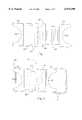
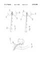
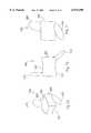
- FIGS. 1 and 2depict an embodiment of an implant of the invention which is adjustable in order to select the amount of distraction required.
- FIG. 1depicts the implant in a more extended configuration than does FIG. 2.
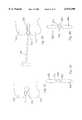
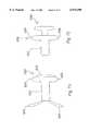
- FIGS. 3a and 3bdepict side and end views of a first forked and of the embodiment of FIG. 1.
- FIGS. 4a and 4bdepict side sectioned and end views of an interbody piece of the implant of FIG. 1.
- FIGS. 5a and 5bdepict side and end views of a second forked end of the embodiment of FIG. 1.
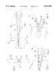
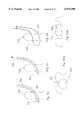
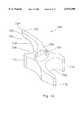
- FIGS. 6, 7, 8, 9 and 10depict apparatus and method for another embodiment of the present invention for creating distraction between adjacent spinous processes.
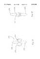
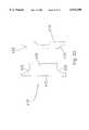
- FIGS. 11, 12 and 13depict yet a further embodiment of the invention for creating distraction between adjacent spinous processes.
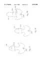
- FIGS. 14 and 15depict a further apparatus and method of an embodiment of the invention for creating distraction.
- FIGS. 16, 16a, and 17depict yet another embodiment of the present invention.
- FIGS. 18, 19 and 20depict yet a further apparatus and method of the present embodiment.
- FIGS. 21 and 22depict still a further embodiment of the present invention.
- FIGS. 23, 24 and 25depict another embodiment of the present invention.
- FIGS. 26, 27 and 28depict another embodiment of the invention.
- FIGS. 29 and 30depict side elevational views of differently shaped implants of embodiments of the present invention.
- FIGS. 31, 32 and 33depict various implant positions of an apparatus of the present invention.
- FIGS. 34 and 35depict yet another apparatus and method of the present invention.
- FIGS. 36, 37 and 38depict three different embodiments of the present invention.
- FIGS. 39 and 40depict yet another apparatus and method of an embodiment of the present invention.
- FIGS. 41, 42 and 43depict yet further embodiments of an apparatus and method of the present invention.
- FIG. 44is still a further embodiment of an implant of the invention.
- FIG. 45is yet another depiction of an apparatus and method of the invention.
- FIGS. 46 and 47depict still a further apparatus and method of an embodiment of the invention.
- FIGS. 48, 49, 50 and 51depict yet a further apparatus and method of the invention.
- FIGS. 52, 53, 54, 55a and 55bdepict another apparatus and method of the invention.
- FIGS. 56, 57 and 58depict yet a further apparatus and method of the invention.
- FIGS. 59 and 60depict still a further embodiment of the invention.
- FIG. 61depict another embodiment of the invention.
- FIGS. 62 and 63depict yet another embodiment of the present invention.
- FIGS. 64 and 65depict still a further embodiment of the present invention.
- FIG. 66depicts another embodiment of the invention.
- FIGS. 67 and 68depict yet another embodiment of the present invention.
- FIGS. 69, 70, 71 and 71adepict a further embodiment of the present invention.
- FIGS. 72 and 73depict still another embodiment of the invention.
- FIGS. 74, 75, 76, 77, and 78depict still other embodiments of the invention.
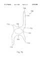
- Implant 20includes first and second forked ends 22 and 24, each defining a saddle 26, 28 respectively.
- the forked ends 22, 24are mated using an interbody piece 30.
- the first forked end 22includes a threaded shaft 32 which projects rearwardly from the saddle 26.
- the threaded shaft 32fits into the threaded bore 34 (FIG. 4a) of the interbody piece 30.
- the second forked end 24(FIGS. 5a, 5b) includes a smooth cylindrical shaft 36 which can fit into the smooth bore 38 of the interbody piece 30.
- FIG. 1shows the implant 20 in a fully extended position
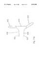
- FIG. 2shows the implant in an unextended position.
- the threaded shaft 32 of the first forked end 22fits inside the hollow cylindrical shaft 36 of the second forked end 24.
- the implant 20For purposes of implantation between adjacent first and second spinous processes of the spinal column, the implant 20 is configured as shown in FIG. 2.
- the first and second spinous processesare exposed using appropriate surgical techniques and thereafter, the implant 20 is positioned so that saddle 26 engages the first spinous process, and saddle 28 engages the second spinous process.
- the interbody piece 30can be rotated by placing an appropriate tool or pin into the cross holes 40 and upon rotation, the saddle 26 is moved relative to the saddle 28.
- Such rotationspreads apart or distracts the spinous processes with the resultant and beneficial effect of enlarging the volume of the spinal canal in order to alleviate any restrictions on blood vessels and nerves.
- this implantas well as the several other implants described herein act as an extension stop. That means that as the back is bent backwardly and thereby placed in extension the spacing between adjacent spinous processes cannot be reduced to a distance less than the distance between the lowest point of saddle 26 and the lowest point of saddle 28.
- This implantdoes not inhibit or in any way limit the flexion of the spinal column, wherein the spinal column is bent forward.
- such a deviceprovides for distraction in the range of about 5 millimeters to about 15 millimeters.
- devices which can distract up to and above 22 millimetersmay be used depending on the characteristics of the individual patient.
- the implant 20can be implanted essentially floating in position in order to gain the benefits of the aforementioned extension stop and flexion non-inhibitor.
- one of the saddles 26can be laterally pinned with pin 29 to one of the spinous processes and the other saddle can be loosely associated with the other spinous processes by using a tether 31 which either pierces or surrounds the other spinous process and then is attached to the saddle in order to position the saddle relative to the spinous process.
- both saddlescan be loosely tethered to the adjacent spinous process in order to allow the saddles to move relative to the spinous processes.
- the shape of the saddlesbeing concave, gives the advantage of distributing the forces between the saddle and the respective spinous process. This ensures that the bone is not resorbed due to the placement of the implant 20 and that the structural integrity of the bone is maintained.
- the implant 20 in this embodimentcan be made of a number of materials, including but not limited to, stainless steel, titanium, ceramics, plastics, elastics, composite materials or any combination of the above.
- the modulus of elasticity of the implantcan be matched to that of bone, so that the implant 20 is not too rigid.
- the flexibility of the implantcan further be enhanced by providing additional apertures or perforations throughout the implant in addition to the holes 40 which also have the above stated purpose of allowing the interbody piece 30 to be rotated in order to expand the distance between the saddle 26, 28.
- the spinous processescan be accessed and distracted initially using appropriate instrumentation, and that the implant 20 can be inserted and adjusted in order to maintain and achieve the desired distraction.
- the spinous processcan be accessed and the implant 20 appropriately positioned. Once positioned, the length of the implant can be adjusted in order to distract the spinous processes or extend the distraction of already distracted spinous processes.
- the implantcan be used to create a distraction or to maintain a distraction which has already been created.
- implant 20placement of implants such as implant 20 relative to the spinous process will be discussed hereinbelow with other embodiments. However, it is to be noted that ideally, the implant 20 would be placed close to the instantaneous axis of rotation of the spinal column so that the forces placed on the implant 20 and the forces that the implant 20 places on the spinal column are minimized.
- the methoduses the approach of extending the length of the implant 20 a first amount and then allowing the spine to creep or adjust to this distraction. Thereafter, implant 20 would be lengthened another amount, followed by a period where the spine is allowed to creep or adjust to this new level of distraction. This process could be repeated until the desired amount of distraction has been accomplished.
- This same methodcan be used with insertion tools prior to the installation of an implant. The tools can be used to obtain the desired distraction using a series of spinal distraction and spine creep periods before an implant is installed.
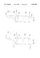
- the embodiment of the invention shown in the above FIGS. 6, 7, 8, 9 and 10includes distraction or spreader tool 50 which has first and second arms 52, 54. Arms 52, 54 are pivotal about pivot point 56 and releaseable from pivot point 56 in order to effect the implantation of implant 58. As can be seen in FIG. 6, in cross-section, the arms 52, 54 are somewhat concave in order to cradle and securely hold the first spinous process 60 relative to arm 52 and the second spinous process 62 relative to arm 54.
- the distraction tool 50can be inserted through a small incision in the back of the patient in order to address the space between the first spinous process 60 and the second spinous process 62. Once the tool 50 is appropriately positioned, the arms 52, 54 can be spread apart in order to distract the spinous processes.
- an implant 58 as shown in FIGS. 8 and 9, or of a design shown in other of the embodiments of this invention,can be urged between the arms 52, 54 and into position between the spinous processes. After this occurs, the arms 52, 54 can be withdrawn from the spinous processes leaving the implant 58 in place.
- the implant 58is urged into place using a tool 64 which can be secured to the implant 58 through a threaded bore 66 in the back of the implant.
- the implant 58includes saddles 68 and 70 which cradle the upper and lower spinous processes 60, 62 in much the same manner as the above first embodiment and also in much the same manner as the individual arms of the tool 50.
- the saddles as described abovetend to distribute the load between the implant and the spinous processes and also assure that the spinous process is stably seated at the lowest point of the respective saddles.
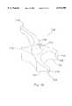
- the spreader or distraction tool 80includes first and second arms 82, 84 which are permanently pivoted at pivot point 86.
- the armsinclude L-shaped ends 88, 90. Through a small incision, the L-shaped ends 88, 90 can be inserted between the first and second spinous processes 92, 94. Once positioned, the arms 82, 84 can be spread apart in order to distract the spinous processes.
- the implant 96can then be urged between the spinous processes in order to maintain the distraction. It is noted that implant 96 includes wedged surfaces or ramps 98, 100. As the implant 96 is being urged between the spinous processes, the ramps further cause the spinous processes to be distracted.
- the implant 96Once the implant 96 is fully implanted, the full distraction is maintained by the planar surfaces 99, 101 located rearwardly of the ramps. It is to be understood that the cross-section of the implant 96 can be similar to that shown for implant 58 or similar to other implants in order to gain the advantages of load distribution and stability.
- the implant 110includes first and second conically shaped members 112, 114.
- Member 112includes a male snap connector 116 and member 114 includes a female snap connector 118. With male snap connector 116 urged into female snap connector 118, the first member 112 is locked to the second member 114.
- a distraction or spreader tool 80could be used.
- an implantation tool 120can be used to position and snap together the implant 110.
- the first member 112 of implant 110is mounted on one arm and second member 114 is mounted on the other arm of tool 120.
- the member 112, 114are placed on opposite sides of the space between adjacent spinous processes.
- the members 11 2, 114are urged together so that the implant 110 is locked in place between the spinous processes as shown in FIG. 15. It is to be noted that the implant 110 can also be made more self-distracting by causing the cylindrical surface 122 to be more conical, much as surface 124 is conical, in order to hold implant 110 in place relative to the spinous processes and also to create additional distraction.
- FIGS. 16 and 17An alternative embodiment of the implant can be seen in FIGS. 16 and 17.
- This implant 130includes first and second members 132, 134.
- the implantsare held together using a screw (not shown) which is inserted through countersunk bore 136 and engages a threaded bore 138 of the second member 134.
- Surfaces 139are flattened (FIG. 17) in order to carry and spread the load applied thereto by the spinous processes.
- the embodiment of implant 130is not circular in overall outside appearance, as is the embodiment 110 of FIGS. 14 and 15.
- this embodimentis truncated so that the lateral side 140, 142 are flattened with the upper and lower sides 144, 146 being elongated in order to capture and create a saddle for the upper and lower spinous processes.
- the upper and lower sides, 144, 146are rounded to provide a more anatomical implant which is compatible with the spinous processes.
- key 148 and keyway 150are designed to mate in a particular manner.
- Key 148includes at least one flattened surface, such as flattened surface 152, which mates to an appropriately flattened surface 154 of the keyway 1 50.
- the first memberis appropriately mated to the second member in order to form appropriate upper and lower saddles holding the implant 130 relative to the upper and lower spinous processes.
- FIG. 16adepicts second member 134 in combination with a rounded nose lead-in plug 135.
- Lead-in plug 135includes a bore 137 which can fit snugly over key 148. In this configuration, the lead-in plug 135 can be used to assist in the placement of the second member 134 between spinous processes. Once the second member 134 is appropriately positioned, the lead-in plug 135 can be removed. It is to be understood that the lead-in plug 135 can have other shapes such as pyramids and cones to assist in urging apart the spinous processes and soft tissues in order to position the second member 134.
- the implant 330 as shown in FIG. 18is comprised of first and second mating wedges 332 and 334.
- the spinous processesare accessed from both sides and then a tool is used to push the wedges towards each other.
- the wedgesmove relative to each other so that the combined dimension of the implant 330 located between the upper and lower spinous processes 336, 338 (FIG. 20), increases, thereby distracting the spinous processes.
- the wedges 332, 334include saddle 340, 342, which receiving the spinous processes 336, 338. These saddles have the advantages as described hereinabove.
- the first or second wedges 332, 334have a mating arrangement which includes a channel 344 and a projection of 346 which can be urged into the channel in order to lock the wedges 332, 334 together.
- the channel 334is undercut in order to keep the projection from separating therefrom.
- a detentcan be located in one of the channel and the projection, with a complimentary recess in the other of the channel and the projection. Once these two snap together, the wedges are prevented from sliding relative to the other in the channel 344.
- the implant 370is comprised of first and second distraction cone 372, 374. These cones are made of a flexible material. The cones are positioned on either side of the spinous processes 376, 378 as shown in FIG. 21. Using appropriate tool as shown hereinabove, the distraction cones 372, 374 are urged together. As they are urged together, the cones distract the spinous processes as shown in FIG. 22. Once this has occurred, an appropriate screw or other type of fastening mechanism 380 can be used to maintain the position of the distraction cones 372, 374.
- the advantage of this arrangementis that the implant 370 is self-distracting and also that the implant, being flexible, molds about the spinous processes as shown in FIG. 22.
- FIGS. 23 and 24another embodiment of the implant 170 is depicted.
- This implantis guided in place using an L-shaped guide 172 which can have a concave cross-section such as the cross-section 52 of retraction tool 50 in FIG. 6 in order to cradle and guide the implant 170 in position.
- a small incisionwould be made into the back of the patient and the L-shaped guide tool 172 inserted between the adjacent spinous processes.
- the implant 170would be mounted on the end of insertion tool 174 and urged into position between the spinous processes. The act of urging the implant into position could cause the spinous processes to be further distracted if that is required.
- a distraction toolsuch as shown in FIG. 13 could be used to initially distract the spinous processes.
- Implant 170can be made of a deformable material so that it can be urged into place and so that it can somewhat conform to the shape of the upper and lower spinous processes.
- This deformable materialwould be preferably an elastic material. The advantage of such a material would be that the load forces between the implant and the spinous processes would be distributed over a much broader surface area. Further, the implant would mold itself to an irregular spinous process shape in order to locate the implant relative to spinous processes.
- this implant 176can be inserted over a guide wire, guide tool or stylet 178.
- the guide wire 178is positioned through a small incision to the back of the patient to a position between the adjacent spinous processes.
- the implantis threaded over the guide wire 178 and urged into position between the spinous processes. This urging can further distract the spinous processes if further distraction is required.
- the guide tool 178is removed and the incision closed.
- the insertion tools of FIGS. 23 and 24can also be used if desired.
- FIGS. 26, 27 and 28uses an implant similar to that depicted in FIGS. 8 and 9 with different insertion tools.
- an L-shaped distraction tool 190is similar to L-shaped distraction tool 80 (FIG. 12), is used to distract the first and second spinous processes 192, 194.
- an insertion tool 196is placed between the spinous processes 192, 194.
- Insertion tool 196includes a handle 198 to which is mounted a square-shaped ring 200.
- the distraction tool 190can be inserted through a small incision in the back in order to spread apart the spinous processes.
- an upper end 202 of ring 200can be initially inserted followed by the remainder of the ring 200.
- the ringcan be rotated slightly by moving handle 198 downwardly in order to further wedge the spinous processes apart.
- an implantsuch as implant 204 can be inserted through the ring and properly positioned using implant handle 206. Thereafter, the implant handle 206 and the insertion tool 196 can be removed.
- the implants 210, 212can have different shapes when viewed from the side. These implants are similar to the above-referenced implants 58 (FIG. 8) and 204 (FIG. 28). These implants have cross-sections similar to that shown in FIG. 10 which includes saddles in order to receive and hold the adjacent spinous processes.
- these implantscan be placed in different positions with respect to the spinous process 214.
- the implant 210is placed closest to the lamina 216. Being so positioned, the implant 210 is close to the instantaneous axis of rotation 218 of the spinal column, and the implant would experience least forces caused by movement of the spine. Thus, theoretically, this is the optimal location for the implant.
- the implantcan be placed midway along the spinous process (FIG. 32) and towards the posterior aspect of the spinous process (FIG. 31). As positioned shown in FIG. 31, the greatest force would be placed on the implant 210 due to a combination of compression and extension of the spinal column.
- implant 220is comprised of a plurality of individual leaves 222 which are substantially V-shaped.
- the leavesinclude interlocking indentations or detents 224. That is, each leaf includes an indentation with a corresponding protrusion such that a protrusion of one leaf mates with an indentation of an adjacent leaf.
- an insertion tool 226which has a blunt end 228 which conforms to the shape of an individual leaf 222. For insertion of this implant into the space between the spinous processes as shown in FIG. 34, the insertion tool 226 first insert a single leaf 220.
- the insertion toolthen inserts a second leaf with the protrusion 224 of the second leaf snapping into corresponding indentation made by the protrusion 224 of the first leaf.
- This processwould reoccur with third and subsequent leaves until the appropriate spacing between the spinous processes was built up.
- the lateral edges 229 of the individual leaves 222are slightly curved upwardly in order to form a saddle for receiving the upper and lower spinous processes.
- FIGS. 36, 37 and 38which include implants 230, 232, and 234 respectively, are designed in such a manner so the implant locks itself into position once it is properly positioned between the spinous processes.
- Implant 220is essentially a series of truncated cones and includes a plurality of ever expanding steps 236. These steps are formed by the conical bodies starting with the nose body 238 followed there behind by conical body 240. Essentially, the implant 234 looks like a fir tree placed on its side.
- the implant 230is inserted laterally throughout the opening between upper and lower spinous processes.
- the first body 238causes the initial distraction. Each successive conical body distracts the spinous processes a further incremental amount.
- the spinous processesare locked into position by steps 236.
- the initial nose body 238 of the implant and other bodies 240can be broken, snapped or sawed off if desired in order to minimize the size of the implant 230.
- the intersection between bodies such as body 238 and 240which is intersection line 242
- intersection line 244 between the bodies which remain between the spinous processeswould not need to be weaker, as there would be no intention that the implant would be broken off at this point.
- FIG. 37shows implant 232 positioned between upper and lower spinous processes.
- This implantis wedge-shaped or triangular shaped in cross-sectioned and includes bore pluralities 245 and 246. Through these bores can be placed locking pins 248 and 250. The triangular or wedged-shaped implant can be urged laterally between and thus distract the upper and lower spinous processes. Once the appropriate distraction is reached, pins 248, 250 can be inserted through the appropriate bores of the bore pluralities 245 and 246 in order to lock the spinous processes in a V-shaped valley formed by pins 248, 250 on the one hand and the ramped surface 233, 235 on the other hand.
- the implant 234has a triangular-shaped or wedge-shaped body similar to that shown in FIG. 37.
- tab 252, 254are pivotally mounted to the triangular shaped body 234. Once the implant 234 is appropriately positioned in order to distract the spinous processes to the desired amount, the tabs 252, 254 rotate into position in order to hold the implant 234 in the appropriate position.
- cannula 258is inserted through a small incision to a position between upper and lower spinous processes. Once the cannula is properly inserted, an implant 260 is pushed through the cannula 258 using an insertion tool 262.
- the implant 260includes a plurality of ribs or indentation 264 that assist in positioning the implant 260 relative to the upper and lower spinal processes. Once the implant 260 is in position, the cannula 258 is withdrawn so that the implant 260 comes in contact with and wedges between the spinous processes.
- the cannula 258is somewhat conical in shape with the nose end 266 being somewhat smaller than the distal end 268 in order to effect the insertion of the cannula into the space between the spinous processes.
- a plurality of cannulacan be used instead of one, with each cannula being slightly bigger than one before.
- the first smaller cannulawould be inserted followed by successively larger cannula being placed over the previous smaller cannula.
- the smaller cannulawould then be withdrawn from the center of the larger cannula. Once the largest cannula is in place, and the opening of the skin accordingly expanded, the implant, which is accommodated by only the larger cannula, is inserted through the larger cannula and into position.
- the precurved implant 270 in FIGS. 41 and 42, and precurved implant 272 in FIG. 43have common introduction techniques which includes a guide wire, guide tool, or stylet 274.
- the guide wire 274is appropriately positioned through the skin of the patient and into the space between the spinous processes. After this is accomplished, the implant is directed over the guide wire and into position between the spinous processes.
- the precurved nature of the implantassist in (1) positioning the implant through a first small incision in the patient's skin on one side of the space between two spinous processes and (2) guiding the implant toward a second small incision in the patient's skin on the other side of the space between the two spinous processes.
- the implantincludes a conical introduction nose 276 and a distal portion 278. As the nose 276 is inserted between the spinous processes, this causes distraction of the spinous processes. Break lines 280, 282 are established at opposite sides of the implant 270. Once the implant is properly positioned over the guide wire between the spinous processes, the nose portion 276 and the distal portion 278 can be broken off along the break lines, through the above two incisions, in order to leave the implant 270 in position.
- break lines 280, 282can be provided on implant 270 so that the implant can continue to be fed over the guide wire 278 until the appropriate width of the implant 270 creates the desired amount of distraction.
- the break linescan be created by perforating or otherwise weakening the implant 270 so that the appropriate portions can be snapped or sawed off.
- this implantis similar in design to the implant 230 shown in FIG. 36.
- This implant 272 in FIG. 47is precurved and inserted over a guide wire 274 to a position between the spinous processes.
- sections of the implant 272can be broken, snapped or sawed off as described hereinabove in order to leave a portion of the implant wedged between the upper and lower spinous processes.
- FIG. 44A further embodiment of the invention is shown in FIG. 44.
- This embodimentincludes a combination insertion tool and implant 290.
- the insertion tool and implant 290is in the shape of a ring which is hinged at point 292.
- the ringis formed by a first elongated and conically shaped member 294 and a second elongated and conically shaped member 296.
- Members 294 and 296terminate in points and through the use of hinge 292 are aligned and meet.
- first member and second memberare inserted through the skins of the patient and are mated together between the spinous processes.
- the implant 290is rotated, for example clockwise, so that increasingly widening portions of the first member 292 are used to distract the first and second spinous processes.
- the remainder of the ring before and after the section which is located between the spinous processescan be broken off as taught hereinabove in order to maintain the desired distraction.
- the entire ringcan be left in place with the spinous processes distracted.
- the implant 300is comprised of a plurality of rods or stylets 302 which are inserted between the upper and lower spinous is processes.
- the rodsare designed much as described hereinabove so that they may be broken, snapped or cut off. Once these are inserted and the appropriate distraction has been reached, the stylets are broken off and a segment of each stylet remains in order to maintain distraction of the spinous process.
- Implant 310 of FIGS. 46 and 47is comprised of a shape memory material which coils upon being released.
- the materialis straightened out in a delivery tool 312.
- the delivery toolis in position between upper and lower spinous processes 314, 316.
- the materialis then pushed through the delivery tool.
- the materialcoils, distracting the spinous processes to the desired amount. Once this distraction has been achieved, the material is cut and the delivery tool removed.
- FIGS. 48, 49, 50 and 51Embodiments of FIGS. 48, 49, 50 and 51
- the implant 320is delivered between upper and lower spinous processes 322 and 324, by delivery tool 326.
- the delivery toolis given a 90° twist so that the implant goes from the orientation as shown in FIG. 49, with longest dimension substantially perpendicular to the spinous processes, to the orientation shown in FIG. 50 where the longest dimension is in line with and parallel to the spinous processes.
- This rotationcauses the desired distraction between the spinous processes.
- Implant 320includes opposed recesses 321 and 323 located at the ends thereof. Rotation of the implant 320 causes the spinous processes to become lodged in these recesses.
- the insertion tool 326can be used to insert multiple implants 320, 321 into the space between the spinous processes 322, 324 (FIG. 51). Multiple implants 320, 321 can be inserted until the appropriate amount of distraction is built up. It is to be understood in this situation that one implant would lock to another implant by use of, for example, a channel arrangement wherein a projection from one of the implants would be received into and locked into a channel of the other implant. Such a channel arrangement is depicted with respect to the other embodiment.
- FIGS. 52 through 55bis comprised of a fluid-filled dynamic distraction implant 350.
- This implantincludes a membrane 352 which is placed over pre-bent insertion rod 354 and then inserted through an incision on one side of the spinous process 356.
- the bent insertion rod, with the implant 350 thereover,is guided between appropriate spinous processes. After this occurs, the insertion rod 354 is removed leaving the flexible implant in place.
- the implant 350is then connected to a source of fluid (gas, liquid, gel and the like) and the fluid is forced into the implant causing it to expand as shown in FIG. 54, distracting the spinal processes to the desired amount.
- the implant 350is closed off as is shown in FIG. 55a.
- the implant 350being flexible, can mold to the spinous processes which may be of irregular shape, thus assuring positioning. Further, implant 350 acts as a shock absorber, damping forces and stresses between the implant and the spinous processes.
- a variety of materialscan be used to make the implant and the fluid which is forced into the implant.
- viscoelastic substancessuch as methylcellulose, or hyaluronic acid can be used to fill the implant.
- materials which are initially a fluid, but later solidifycan be inserted in order to cause the necessary distraction. As the materials solidify, they mold into a custom shape about the spinous processes and accordingly are held in position at least with respect to one of two adjacent spinous processes.
- the implantcan be formed about one spinous process in such a manner that the implant stays positioned with respect to that spinous process (FIG. 55b).
- a single implantcan be used as an extension stop for spinous process located on either side, without restricting flexion of the spinal column.
- the implant 360 as shown in FIG. 56is comprised of a shape memory material such as a plastic or a metal.
- a curved introductory tool 362is positioned between the appropriate spinous processes as described hereinabove. Once this has occurred, bore 364 of the implant is received over the tool. This act can cause the implant to straighten out. The implant is then urged into position and thereby distracts the spinous processes. When this has occurred, the insertion tool 362 is removed, allowing the implant to assume its pre-straightened configuration and is thereby secured about one of the spinous processes.
- the implantcan be temperature sensitive. That is to say that the implant would be more straightened initially, but become more curved when it was warmed by the temperature of the patient's body.
- the implant 380is comprised of a plurality of interlocking leaves 382. Initially, a first leaf is positioned between opposed spinous processes 384, 386. Then subsequently, leafs 382 are interposed between the spinous processes until the desired distraction has been built up. The leaves are somewhat spring-like in order to absorb the shock and can somewhat conform to the spinous processes.
- the implant 390 of FIG. 61includes the placement of shields 392, 394 over adjacent spinous processes 396, 398.
- the shieldsare used to prevent damage to the spinous processes.
- These shieldsinclude apertures which receives a self-tapping screw 400, 402.
- the shieldsare affixed to the spinous processes and the spinous processes are distracted in the appropriate amount. Once this has occurred, a rod 404 is used to hold the distracted position by being screwed into each of the spinous processes through the aperture in the shields using the screws as depicted in FIG. 61.
- Implant 410 of FIGS. 62, 63is comprised of first and second members 412, 414 which can be mated together using an appropriate screw and threaded bore arrangement to form the implant 410.
- Main member 412 and mating member 414form implant 410.
- the implant 410would have a plurality of members 414 for use with a standardized first member 412.
- FIGS. 62 and 63show different types of mating members 414.
- the mating member 414includes projections 416 and 418 which act like shims. These projections are used to project into the space of saddles 420, 422 of the first member 412. These projections 41 6, 418 can be of varying lengths in order to accommodate different sizes of spinous processes.
- a groove 424is placed between the projections 416, 418 and mates with an extension 426 of the first member 412.
- FIGS. 64, 65 and 66are similar in design and concept to the embodiment of FIGS. 62 and 63.
- the implant 500includes the first and second members 502, 504. These members can be secured together with appropriate screws or other fastening means as taught in other embodiments.
- Implant 500includes first and second saddles 506, 508 which are formed between the ends of first and second members 502, 504. These saddles 506, 508 are used to receive and cradle the adjacent spinous processes. As can be seen in FIG. 64, each saddle 506, 508 is defined by a single projection or leg 510, 512, which extends from the appropriate first and second members 502, 504. Unlike the embodiment found in FIGS.
- each of the saddlesis defined by only a single leg as the ligaments and other tissues associated with the spinous processes can be used to ensure that the implant is held in an appropriate position.
- FIG. 64it is easier to position the implant relative to the spinous processes as each saddle is defined by only a single leg and thus the first and second members can be more easily worked into position between the various tissues.
- the implant 520is comprised of a single piece having saddles 522 and 524.
- the saddlesare defined by a single leg 526, 528 respectively.
- an incisionis made between lateral sides of adjacent spinous processes.
- the single leg 526is directed through the incision to a position adjacent to an opposite lateral side of the spinous process with the spinous process cradled in the saddle 522.
- the spinous processesare then urged apart until saddle 524 can be pivoted into position into engagement with the other spinous process in order to maintain the distraction between the two adjacent spinous processes.
- FIG. 66is similar to that of FIG. 65 with an implant 530 and first and second saddles 532 and 534. Associated with each saddle is a tether 536, 538 respectively.
- the tethersare made of flexible materials known in the trade and industry and are positioned through bores in the implant 530. Once appropriately positioned, the tethers can be tied off. It is to be understood that the tethers are not meant to be used to immobilize one spinous process relative to the other, but are used to guide motion of the spinous processes relative to each other so that the implant 530 can be used as an extension stop and a flexion non-inhibitor.
- the saddles 532, 534are used to stop spinal column backward bending and extension. However, the tethers do not inhibit forward bending and spinal column flexion.
- the implant 550is Z-shaped and includes a central body 552 and first and second arms 554, 556, extending in opposite directions therefrom.
- the central body 552 of the implant 550includes first and second saddles 558 and 560.
- the first and second saddles 558 and 560would receive upper and lower spinous processes 562, 568.
- the arms 554, 556are accordingly located adjacent the distal end 566 (FIG. 68) of the central body 552.
- the first and second arms 554, 556act to inhibit forward movement, migration or slippage of the implant 550 toward the spinal canal and keep the implant in place relative to the first and second spinal processes. This prevents the implant from pressing down on the ligamentum flavum and the dura.
- the central bodywould have a height of about 10 mm with each of the arms 554, 556 have a height of also about 10 mm. Depending on the patient, the height of the body could vary from about less than 10 mm to about greater than 24 mm.
- the first and second arms 554, 556are additionally contoured in order to accept the upper and lower spinous processes 556, 558.
- the arms 554, 556 as can be seen with respect to arm 554have a slightly outwardly bowed portion 568 (FIG. 68) with a distal end 570 which is slightly inwardly bowed.
- This configurationallows the arm to fit about the spinous process with the distal end 570 somewhat urged against the spinous process in order to guide the motion of the spinous process relative to the implant.
- These arms 554, 556could if desired to be made more flexible than the central body 552 by making arms 554, 556 thin and/or with perforations, and/or other material different than that of the central body 550.
- this embodimentcan be urged into position between adjacent spinous processes by directing an arm into a lateral incision so that the central body 552 can be finally positioned between spinous processes.
- FIGS. 69, 70 and 71are perspective front, end, and side views of implant 580 of the invention.
- This implantincludes a central body 582 which has first and second saddles 584, 586 for receiving adjacent spinous processes. Additionally, the implant 580 includes first and second arms 588 and 590. The arms, as with the past embodiment, prevent forward migration or slippage of the implant toward the spinal canal.
- First arm 588projects outwardly from the first saddle 584 and second arm 590 projects outwardly from the second saddle 586.
- the first arm 588is located adjacent to the distal end 600 of the central body 582 and proceeds only partly along the length of the central body 582.
- the first arm 588is substantially perpendicular to the central body as shown in FIG. 70. Further, the first arm 588, as well as the second arm 590, is anatomically rounded.
- the second arm 590projecting from second saddle 586, is located somewhat rearward of the distal end 600, and extends partially along the length of the central body 582.
- the second arm 590projects at a compound angle from the central body 582.
- the second arm 590is shown to be at about an angle of 45° from the saddle 586 (FIG. 70). Additionally, the second arm 590 is at an angle of about 45° relative to the length of the central body 580 as shown in FIG. 71. It is to be understood that other compound angles are within the spirit and scope of the invention as claimed.
- the first and second arms 588, 590have a length which is about the same as the width of the central body 582.
- the length of each armis about 10 mm and the width of the central body is about 10 mm.
- the bodies with the widths of 24 mm and greaterare within the spirit and scope of the invention, along with first and second arms ranging from about 10 mm to greater than about 24 mm.
- the embodimentcould include a central body having a width of about or greater than 24 mm with arms being at about 10 mm.
- FIGS. 69, 70 and 71are designed to preferably be positioned between the L4-L5 and the L5-S1 vertebral pairs.
- the embodiment of FIGS. 69, 70, 71is particularly designed for the L5-S1 position with the arms being designed to conform to the sloping surfaces found therebetween. The first and second arms are thus contoured so that they lie flat against the lamina of the vertebra which has a slight angle.
- FIGS. 69, 70, and 71as with the embodiment of FIGS. 67 and 68 is Z-shaped in configuration so that it may be inserted from one lateral side to a position between adjacent spinous processes. A first arm, followed by the central body, is guided through the space between the spinous processes. Such an arrangement only requires that a incision on one side of the spinous process be made in order to successfully implant the device between the two spinous processes.
- the implant 610 of FIG. 71ais similar to that immediately above with the first arm 612 located on the same side of the implant as the second arm 614.
- the first and second saddle 616, 618are slightly modified in that distal portion 620, 622 are somewhat flattened from the normal saddle shape in order to allow the implant to be positioned between the spinous processes from one side. Once in position, the ligaments and tissues associated with the spinous processes would hold the implant into position. Tethers also could be used if desired.
- Implant 630is also designed so that it can be inserted from one side of adjacent spinous processes.
- This insert 630includes a central body 632 with the first and second arms 634, 636 extending on either side thereof.
- a plunger 638is positioned to extend from an end of the central body 632.
- the plunger 638is fully extended and as shown in FIG. 73, the plunger 638 is received within the central body 632 of the implant 630.
- the third and fourth arms or hooks 640, 642can extend outwardly from the central body 632.
- the third and fourth arms or hooks 640, 642can be comprised of a variety of materials, such as for example, shape memory metal materials or materials which have a springy quality.
- the plunger 638is pulled outwardly as shown in FIG. 72.
- the central body 632is then positioned between adjacent spinous processes and the plunger 638 is allowed to move to the position of FIG. 73 so that the third and fourth arms 640, 642 can project outwardly from the central body 632 in order to hold the implant 630 in position between the spinous processes.
- Plunger 638can be spring biased to the position as shown in FIG. 73 or can include detents or other mechanisms which lock it into that position. Further, the third and fourth arms themselves, as deployed, can keep the plunger in the position as shown in FIG. 73.
- FIGS. 74 through 78disclose implant 700.
- Implant 700is particularly suited for implantation between the L4-L5 and L5-S1 vertebra.
- the implant 700includes a central body 702 which has a bore 704 provided therein.
- Bore 704is used in order to adjust the modulus of elasticity of the implant so that it is preferably approximately two times the anatomical load placed on the vertebra in extension.
- the implant 700is approximately two times stiffer than the normal load placed on the implant.
- modulus valuescan be used and be within the spirit of the invention.
- Implant 700includes first and second saddle 706, 708 which are used to receive and spread the load from the upper and lower spinous processes.
- the saddle 706is defined by first and second arms 710 and 712.
- the second saddle 708is defined by third and fourth arms 714 and 716.
- the first arm 710in a preferred embodiment, is approximately two times the length of the body 702 with the second arm being approximately less than a quarter length of the body.
- Third arm 714is approximately one times the length of the body 702 with the fourth arm 716 being, in this preferred embodiment, approximately one and a half times the length of the body 702.
- the armsare designed in such a way that the implant (1) can be easily and conveniently inserted between the adjacent spinous processes, (2) will not migrate forwardly toward the spinal canal, and (3) will hold its position through flexion and extension as well as lateral bending of the spinal column.
- First arm 710is in addition designed to acco mmodate the shape of the vertebra. As can be seen in FIG. 74, the first arm 710 becomes narrower as it extends away from the body 702.
- the first arm 710includes a sloping portion 718 followed by a small recess 720 ending in a rounded portion 722 adjacent to the end 724.
- This designis provided to accommodate the anatomical form of for example the L4 vertebra. It is to be understood that these vertebra have a number of surfaces at roughly 30° angles and that the sloping surfaces of this embodiment and the embodiments shown in FIGS. 77 and 78 are designed to accommodate these surfaces. These embodiments can be further modified in order to accommodate other angles and shapes.
- the second arm 712is small so that it is easy to insert between the spinous processes, yet still define the saddle 706.
- the fourth arm 716is larger than the third arm 714, both of which are smaller than the first arm 710.
- the third and fourth armsare designed so that they define the saddle 706, guide the spinous processes relative to the implant 700 during movement of the spinal column, and yet are of a size which makes the implant easy to position between the spinous processes.
- the procedure, by way of example only, for implanting the implant 700can be to make an incision laterally between two spinous processes and then initially insert first arm 710 between the spinous processes.
- the implant and/or appropriate toolswould be used to distract the spinous processes allowing the third leg 714 and the central body 702 to fit through the space between the spinous processes.
- the third leg 714would then come to rest adjacent the lower spinous processes on the opposite side with the spinous processes resting in the first and second saddle 706, 708.
- the longer fourth leg 716would then assist in the positioning of the implant 700.
- FIG. 77includes an implant 740 which is similar to implant 700 and thus have similar numbering.
- the saddle 706, 708 of implant 740have been cantered or sloped in order to accommodate the bone structure between, by way of example, the L4-L5 and the L5-S1 vertebra.
- the vertebra in this areahave a number of sloping surfaces in the range of about 30°. Accordingly, saddle 706 is sloped at less than 30° and preferably about 20° while saddle 708 is sloped at about 30° and preferably more than 30°.
- the implant 760 as shown in FIG. 78is similar to implant 700 in FIG. 74 and is similarly numbered.
- Implant 760includes third and fourth legs 714, 716 which have sloping portions 762, 764 which slope toward ends 766, 768 of third and fourth arm 714, 716 respectively.
- the sloping portionsaccommodate the form of the lower vertebra against which they are positioned. In the preferred embodiment, the sloping portions are of about 30°. However, it is to be understood that sloping portions which are substantially greater and substantially less than 30° can be included and be within the spirit and scope of the invention.
- the present inventioncan be used to relieve pain caused by spinal stenosis in the form of, by way of example only, central canal stenosis or foraminal (lateral) stenosis. These implants have the ability to flatten the natural curvature of the spine and open the neural foramen and the spacing between adjacent vertebra to relieve problems associated with the above-mentioned lateral and central stenosis. Additionally, the invention can be used to relieve pain associated with facet arthropathy. The present invention is minimally invasive and can be used on an outpatient basis.
Landscapes
- Health & Medical Sciences (AREA)
- Orthopedic Medicine & Surgery (AREA)
- Life Sciences & Earth Sciences (AREA)
- Neurology (AREA)
- Surgery (AREA)
- Veterinary Medicine (AREA)
- Animal Behavior & Ethology (AREA)
- General Health & Medical Sciences (AREA)
- Public Health (AREA)
- Nuclear Medicine, Radiotherapy & Molecular Imaging (AREA)
- Engineering & Computer Science (AREA)
- Biomedical Technology (AREA)
- Heart & Thoracic Surgery (AREA)
- Medical Informatics (AREA)
- Molecular Biology (AREA)
- Medicinal Chemistry (AREA)
- Chemical & Material Sciences (AREA)
- Epidemiology (AREA)
- Pharmacology & Pharmacy (AREA)
- Prostheses (AREA)
Abstract
Description
Claims (14)
Priority Applications (10)
| Application Number | Priority Date | Filing Date | Title |
|---|---|---|---|
| US09/018,479US6074390A (en) | 1997-01-02 | 1998-02-05 | Spine distraction implant and method |
| US09/360,955US6149652A (en) | 1997-01-02 | 1999-07-27 | Spine distraction implant and method |
| US09/361,513US6500178B2 (en) | 1997-01-02 | 1999-07-27 | Spine distraction implant and method |
| US09/473,184US6238397B1 (en) | 1997-01-02 | 1999-12-28 | Spine distraction implant and method |
| US09/507,755US6280444B1 (en) | 1997-01-02 | 2000-02-18 | Spine distraction implant and method |
| US09/754,534US6419677B2 (en) | 1997-01-02 | 2001-01-04 | Spine distraction implant and method |
| US09/684,017US6796983B1 (en) | 1997-01-02 | 2001-01-08 | Spine distraction implant and method |
| US09/799,215US7101375B2 (en) | 1997-01-02 | 2001-03-05 | Spine distraction implant |
| US09/808,827US6478796B2 (en) | 1997-01-02 | 2001-03-15 | Spin distraction implant and method |
| PCT/US2001/022968WO2002007623A1 (en) | 1997-01-02 | 2001-07-20 | Spine distraction implant |
Applications Claiming Priority (2)
| Application Number | Priority Date | Filing Date | Title |
|---|---|---|---|
| US08/778,093US5836948A (en) | 1997-01-02 | 1997-01-02 | Spine distraction implant and method |
| US09/018,479US6074390A (en) | 1997-01-02 | 1998-02-05 | Spine distraction implant and method |
Related Parent Applications (3)
| Application Number | Title | Priority Date | Filing Date |
|---|---|---|---|
| US08/778,093DivisionUS5836948A (en) | 1997-01-02 | 1997-01-02 | Spine distraction implant and method |
| US08/778,093ContinuationUS5836948A (en) | 1997-01-02 | 1997-01-02 | Spine distraction implant and method |
| US08/958,281ContinuationUS5860977A (en) | 1997-01-02 | 1997-10-27 | Spine distraction implant and method |
Related Child Applications (5)
| Application Number | Title | Priority Date | Filing Date |
|---|---|---|---|
| US09/139,333DivisionUS5876404A (en) | 1997-01-02 | 1998-08-25 | Spine distraction implant and method |
| US09/361,513DivisionUS6500178B2 (en) | 1997-01-02 | 1999-07-27 | Spine distraction implant and method |
| US09/360,955DivisionUS6149652A (en) | 1997-01-02 | 1999-07-27 | Spine distraction implant and method |
| US09/473,184ContinuationUS6238397B1 (en) | 1997-01-02 | 1999-12-28 | Spine distraction implant and method |
| US09/473,184DivisionUS6238397B1 (en) | 1997-01-02 | 1999-12-28 | Spine distraction implant and method |
Publications (1)
| Publication Number | Publication Date |
|---|---|
| US6074390Atrue US6074390A (en) | 2000-06-13 |
Family
ID=25112286
Family Applications (13)
| Application Number | Title | Priority Date | Filing Date |
|---|---|---|---|
| US08/778,093Expired - LifetimeUS5836948A (en) | 1997-01-02 | 1997-01-02 | Spine distraction implant and method |
| US09/018,479Expired - LifetimeUS6074390A (en) | 1997-01-02 | 1998-02-05 | Spine distraction implant and method |
| US09/124,203Expired - LifetimeUS6090112A (en) | 1997-01-02 | 1998-07-28 | Spine distraction implant and method |
| US09/360,955Expired - LifetimeUS6149652A (en) | 1997-01-02 | 1999-07-27 | Spine distraction implant and method |
| US09/361,510Expired - Fee RelatedUS6379355B1 (en) | 1997-01-02 | 1999-07-27 | Spine distraction implant and method |
| US09/361,513Expired - Fee RelatedUS6500178B2 (en) | 1997-01-02 | 1999-07-27 | Spine distraction implant and method |
| US09/473,184Expired - LifetimeUS6238397B1 (en) | 1997-01-02 | 1999-12-28 | Spine distraction implant and method |
| US09/507,755Expired - LifetimeUS6280444B1 (en) | 1997-01-02 | 2000-02-18 | Spine distraction implant and method |
| US09/684,748Expired - LifetimeUS6419676B1 (en) | 1997-01-02 | 2000-10-06 | Spine distraction implant and method |
| US09/686,150Expired - Fee RelatedUS6451020B1 (en) | 1997-01-02 | 2000-12-07 | Spine distraction implant and method |
| US09/754,534Expired - Fee RelatedUS6419677B2 (en) | 1997-01-02 | 2001-01-04 | Spine distraction implant and method |
| US09/808,827Expired - Fee RelatedUS6478796B2 (en) | 1997-01-02 | 2001-03-15 | Spin distraction implant and method |
| US11/692,306AbandonedUS20080172057A1 (en) | 1997-01-02 | 2007-03-28 | Spine distraction implant and method |
Family Applications Before (1)
| Application Number | Title | Priority Date | Filing Date |
|---|---|---|---|
| US08/778,093Expired - LifetimeUS5836948A (en) | 1997-01-02 | 1997-01-02 | Spine distraction implant and method |
Family Applications After (11)
| Application Number | Title | Priority Date | Filing Date |
|---|---|---|---|
| US09/124,203Expired - LifetimeUS6090112A (en) | 1997-01-02 | 1998-07-28 | Spine distraction implant and method |
| US09/360,955Expired - LifetimeUS6149652A (en) | 1997-01-02 | 1999-07-27 | Spine distraction implant and method |
| US09/361,510Expired - Fee RelatedUS6379355B1 (en) | 1997-01-02 | 1999-07-27 | Spine distraction implant and method |
| US09/361,513Expired - Fee RelatedUS6500178B2 (en) | 1997-01-02 | 1999-07-27 | Spine distraction implant and method |
| US09/473,184Expired - LifetimeUS6238397B1 (en) | 1997-01-02 | 1999-12-28 | Spine distraction implant and method |
| US09/507,755Expired - LifetimeUS6280444B1 (en) | 1997-01-02 | 2000-02-18 | Spine distraction implant and method |
| US09/684,748Expired - LifetimeUS6419676B1 (en) | 1997-01-02 | 2000-10-06 | Spine distraction implant and method |
| US09/686,150Expired - Fee RelatedUS6451020B1 (en) | 1997-01-02 | 2000-12-07 | Spine distraction implant and method |
| US09/754,534Expired - Fee RelatedUS6419677B2 (en) | 1997-01-02 | 2001-01-04 | Spine distraction implant and method |
| US09/808,827Expired - Fee RelatedUS6478796B2 (en) | 1997-01-02 | 2001-03-15 | Spin distraction implant and method |
| US11/692,306AbandonedUS20080172057A1 (en) | 1997-01-02 | 2007-03-28 | Spine distraction implant and method |
Country Status (2)
| Country | Link |
|---|---|
| US (13) | US5836948A (en) |
| DE (1) | DE69738301T2 (en) |
Cited By (295)
| Publication number | Priority date | Publication date | Assignee | Title |
|---|---|---|---|---|
| US6443987B1 (en) | 2000-09-15 | 2002-09-03 | Donald W. Bryan | Spinal vertebral implant |
| US20020165550A1 (en)* | 1999-10-21 | 2002-11-07 | George Frey | Devices and techniques for a posterior lateral disc space approach |
| US6500206B1 (en) | 2000-09-15 | 2002-12-31 | Donald W. Bryan | Instruments for inserting spinal vertebral implant |
| US6595998B2 (en) | 2001-03-08 | 2003-07-22 | Spinewave, Inc. | Tissue distraction device |
| US20030204259A1 (en)* | 2000-12-13 | 2003-10-30 | Goble E. Marlowe | Multiple facet joint replacement |
| US20030220691A1 (en)* | 2002-05-23 | 2003-11-27 | Pioneer Laboratories, Inc. | Artificial intervertebral disc device |
| US20040002708A1 (en)* | 2002-05-08 | 2004-01-01 | Stephen Ritland | Dynamic fixation device and method of use |
| US20040030346A1 (en)* | 1999-10-21 | 2004-02-12 | George Frey | Devices and techniques for a posterior lateral disc space approach |
| US6733534B2 (en) | 2002-01-29 | 2004-05-11 | Sdgi Holdings, Inc. | System and method for spine spacing |
| US20040126557A1 (en)* | 2000-12-07 | 2004-07-01 | Lothar Thiele | Stone composite slabs |
| US6764491B2 (en) | 1999-10-21 | 2004-07-20 | Sdgi Holdings, Inc. | Devices and techniques for a posterior lateral disc space approach |
| WO2004084743A1 (en)* | 2003-03-28 | 2004-10-07 | Smart Hospital S.R.L. | Interlaminar vertebral prosthesis |
| US20040249379A1 (en)* | 2003-02-12 | 2004-12-09 | Winslow Charles J. | System and method for immobilizing adjacent spinous processes |
| US20050075634A1 (en)* | 2002-10-29 | 2005-04-07 | Zucherman James F. | Interspinous process implant with radiolucent spacer and lead-in tissue expander |
| US20050090822A1 (en)* | 2003-10-24 | 2005-04-28 | Dipoto Gene | Methods and apparatus for stabilizing the spine through an access device |
| US20050234551A1 (en)* | 2001-03-02 | 2005-10-20 | Facet Solutions, Inc. | Method and apparatus for spine joint replacement |
| US6966910B2 (en) | 2002-04-05 | 2005-11-22 | Stephen Ritland | Dynamic fixation device and method of use |
| US6966929B2 (en) | 2002-10-29 | 2005-11-22 | St. Francis Medical Technologies, Inc. | Artificial vertebral disk replacement implant with a spacer |
| US6991632B2 (en) | 2001-09-28 | 2006-01-31 | Stephen Ritland | Adjustable rod and connector device and method of use |
| US20060058807A1 (en)* | 2004-08-25 | 2006-03-16 | Michael Landry | Expandable interbody fusion device |
| US20060085069A1 (en)* | 2004-10-20 | 2006-04-20 | The Board Of Trustees Of The Leland Stanford Junior University | Systems and methods for posterior dynamic stabilization of the spine |
| US20060084988A1 (en)* | 2004-10-20 | 2006-04-20 | The Board Of Trustees Of The Leland Stanford Junior University | Systems and methods for posterior dynamic stabilization of the spine |
| US20060089654A1 (en)* | 2004-10-25 | 2006-04-27 | Lins Robert E | Interspinous distraction devices and associated methods of insertion |
| US7041136B2 (en) | 2000-11-29 | 2006-05-09 | Facet Solutions, Inc. | Facet joint replacement |
| US20060106381A1 (en)* | 2004-11-18 | 2006-05-18 | Ferree Bret A | Methods and apparatus for treating spinal stenosis |
| US20060106397A1 (en)* | 2004-10-25 | 2006-05-18 | Lins Robert E | Interspinous distraction devices and associated methods of insertion |
| US7083649B2 (en) | 2002-10-29 | 2006-08-01 | St. Francis Medical Technologies, Inc. | Artificial vertebral disk replacement implant with translating pivot point |
| US20060189984A1 (en)* | 2005-02-22 | 2006-08-24 | Medicinelodge, Inc. | Apparatus and method for dynamic vertebral stabilization |
| US20060217728A1 (en)* | 2005-03-28 | 2006-09-28 | Alan Chervitz | Polyaxial reaming apparatus and method |
| US20060229629A1 (en)* | 2003-05-16 | 2006-10-12 | Spine Wave, Inc. | Tissue distraction device |
| US20060241614A1 (en)* | 2005-04-12 | 2006-10-26 | Sdgi Holdings, Inc. | Implants and methods for posterior dynamic stabilization of a spinal motion segment |
| US20060247637A1 (en)* | 2004-08-09 | 2006-11-02 | Dennis Colleran | System and method for dynamic skeletal stabilization |
| US20060271055A1 (en)* | 2005-05-12 | 2006-11-30 | Jeffery Thramann | Spinal stabilization |
| US7166073B2 (en) | 2000-09-29 | 2007-01-23 | Stephen Ritland | Method and device for microsurgical intermuscular spinal surgery |
| US20070043363A1 (en)* | 2005-02-17 | 2007-02-22 | Malandain Hugues F | Percutaneous spinal implants and methods |
| US7207992B2 (en) | 2001-09-28 | 2007-04-24 | Stephen Ritland | Connection rod for screw or hook polyaxial system and method of use |
| US7214186B2 (en) | 2000-09-29 | 2007-05-08 | Stephen Ritland | Method and device for retractor for microsurgical intermuscular lumbar arthrodesis |
| US20070118218A1 (en)* | 2005-11-22 | 2007-05-24 | Hooper David M | Facet joint implant and procedure |
| US20070142915A1 (en)* | 2004-10-20 | 2007-06-21 | Moti Altarac | Systems and methods for posterior dynamic stabilization of the spine |
| US20070161962A1 (en)* | 2006-01-09 | 2007-07-12 | Edie Jason A | Device and method for moving fill material to an implant |
| US20070161993A1 (en)* | 2005-09-27 | 2007-07-12 | Lowery Gary L | Interspinous vertebral stabilization devices |
| US20070162129A1 (en)* | 2006-01-09 | 2007-07-12 | Edie Jason A | Adjustable insertion device for a vertebral implant |
| US20070203501A1 (en)* | 1997-01-02 | 2007-08-30 | Zucherman James F | Spine distraction implant and method |
| US7273496B2 (en) | 2002-10-29 | 2007-09-25 | St. Francis Medical Technologies, Inc. | Artificial vertebral disk replacement implant with crossbar spacer and method |
| US20070233083A1 (en)* | 2005-12-19 | 2007-10-04 | Abdou M S | Devices and methods for inter-vertebral orthopedic device placement |
| US20070233129A1 (en)* | 2006-02-17 | 2007-10-04 | Rudolf Bertagnoli | Method and system for performing interspinous space preparation for receiving an implant |
| US20070233089A1 (en)* | 2006-02-17 | 2007-10-04 | Endius, Inc. | Systems and methods for reducing adjacent level disc disease |
| US20070270834A1 (en)* | 2006-05-04 | 2007-11-22 | Sdgi Holdings, Inc. | Expandable device for insertion between anatomical structures and a procedure utilizing same |
| US7306628B2 (en) | 2002-10-29 | 2007-12-11 | St. Francis Medical Technologies | Interspinous process apparatus and method with a selectably expandable spacer |
| US20080015609A1 (en)* | 2006-04-28 | 2008-01-17 | Trautwein Frank T | Instrument system for use with an interspinous implant |
| US7320707B2 (en) | 2003-11-05 | 2008-01-22 | St. Francis Medical Technologies, Inc. | Method of laterally inserting an artificial vertebral disk replacement implant with crossbar spacer |
| US20080027545A1 (en)* | 2002-10-29 | 2008-01-31 | Zucherman James F | Interspinous process implants and methods of use |
| US20080046086A1 (en)* | 2005-03-21 | 2008-02-21 | Zucherman James F | Interspinous process implant having a thread-shaped wing and method of implantation |
| US20080051904A1 (en)* | 1997-01-02 | 2008-02-28 | Zucherman James F | Supplemental spine fixation device and method |
| US20080051892A1 (en)* | 2005-02-17 | 2008-02-28 | Malandain Hugues F | Percutaneous spinal implants and methods |
| US20080071280A1 (en)* | 2004-04-28 | 2008-03-20 | St. Francis Medical Technologies, Inc. | System and Method for Insertion of an Interspinous Process Implant that is Rotatable in Order to Retain the Implant Relative to the Spinous Processes |
| US20080167655A1 (en)* | 2007-01-05 | 2008-07-10 | Jeffrey Chun Wang | Interspinous implant, tools and methods of implanting |
| US20080172057A1 (en)* | 1997-01-02 | 2008-07-17 | Zucherman James F | Spine distraction implant and method |
| US20080177333A1 (en)* | 2006-10-24 | 2008-07-24 | Warsaw Orthopedic, Inc. | Adjustable jacking implant |
| US20080183211A1 (en)* | 2007-01-11 | 2008-07-31 | Lanx, Llc | Spinous process implants and associated methods |
| US20080195152A1 (en)* | 2004-10-20 | 2008-08-14 | Moti Altarac | Interspinous spacer |
| US20080208344A1 (en)* | 2007-02-06 | 2008-08-28 | Kilpela Thomas S | Intervertebral Implant Devices and Methods for Insertion Thereof |
| US20080215058A1 (en)* | 1997-01-02 | 2008-09-04 | Zucherman James F | Spine distraction implant and method |
| US20080228225A1 (en)* | 2006-11-30 | 2008-09-18 | Paradigm Spine, Llc | Interlaminar-Interspinous Vertebral Stabilization System |
| US20080255669A1 (en)* | 2007-04-10 | 2008-10-16 | Medicinelodge, Inc. | Interspinous process spacers |
| US20080262617A1 (en)* | 2007-04-19 | 2008-10-23 | Zimmer Gmbh | Interspinous spacer |
| US20080281360A1 (en)* | 2007-05-10 | 2008-11-13 | Shannon Marlece Vittur | Spinous process implants and methods |
| US7455639B2 (en) | 2004-09-20 | 2008-11-25 | Stephen Ritland | Opposing parallel bladed retractor and method of use |
| US20080300598A1 (en)* | 2007-05-31 | 2008-12-04 | Spine Wave, Inc. | Expandable Interbody Fusion Device |
| US20080312741A1 (en)* | 2007-04-10 | 2008-12-18 | David Lee | Adjustable spine distraction implant |
| US20090012614A1 (en)* | 2007-05-08 | 2009-01-08 | Dixon Robert A | Device and method for tethering a spinal implant |
| US20090018658A1 (en)* | 2006-08-09 | 2009-01-15 | Nuvasive, Inc. | Methods and apparatus for treating spinal stenosis |
| US7481839B2 (en) | 2003-12-02 | 2009-01-27 | Kyphon Sarl | Bioresorbable interspinous process implant for use with intervertebral disk remediation or replacement implants and procedures |
| US7481840B2 (en) | 2004-09-29 | 2009-01-27 | Kyphon Sarl | Multi-piece artificial spinal disk replacement device with selectably positioning articulating element |
| US20090054988A1 (en)* | 2007-05-01 | 2009-02-26 | Harold Hess | Interspinous implants and methods for implanting same |
| US7497859B2 (en) | 2002-10-29 | 2009-03-03 | Kyphon Sarl | Tools for implanting an artificial vertebral disk |
| US20090062918A1 (en)* | 2007-08-30 | 2009-03-05 | Jeffrey Chun Wang | Interspinous implant, tools and methods of implanting |
| US7503935B2 (en) | 2003-12-02 | 2009-03-17 | Kyphon Sarl | Method of laterally inserting an artificial vertebral disk replacement with translating pivot point |
| US7507242B2 (en) | 2004-06-02 | 2009-03-24 | Facet Solutions | Surgical measurement and resection framework |
| US7510567B2 (en) | 1997-01-02 | 2009-03-31 | Kyphon Sarl | Spinal implants, insertion instruments, and methods of use |
| US20090088802A1 (en)* | 2000-12-13 | 2009-04-02 | Facet Solutions, Inc. | Prosthesis for the replacement of a posterior element of a vertebra |
| US20090105773A1 (en)* | 2007-10-23 | 2009-04-23 | Warsaw Orthopedic, Inc. | Method and apparatus for insertion of an interspinous process device |
| US20090118833A1 (en)* | 2007-11-05 | 2009-05-07 | Zimmer Spine, Inc. | In-situ curable interspinous process spacer |
| US7549999B2 (en) | 2003-05-22 | 2009-06-23 | Kyphon Sarl | Interspinous process distraction implant and method of implantation |
| US20090164018A1 (en)* | 2007-12-19 | 2009-06-25 | Robert Sommerich | Instruments For Expandable Corpectomy Spinal Fusion Cage |
| US20090164017A1 (en)* | 2007-12-19 | 2009-06-25 | Robert Sommerich | Expandable Corpectomy Spinal Fusion Cage |
| US20090204149A1 (en)* | 2008-02-08 | 2009-08-13 | Malek Michel H | Interlaminar hook |
| US7575600B2 (en) | 2004-09-29 | 2009-08-18 | Kyphon Sarl | Artificial vertebral disk replacement implant with translating articulation contact surface and method |
| US20090216274A1 (en)* | 2008-02-21 | 2009-08-27 | Zimmer Gmbh | Expandable interspinous process spacer with lateral support and method for implantation |
| US7588590B2 (en) | 2003-12-10 | 2009-09-15 | Facet Solutions, Inc | Spinal facet implant with spherical implant apposition surface and bone bed and methods of use |
| US20090292316A1 (en)* | 2007-05-01 | 2009-11-26 | Harold Hess | Interspinous process implants having deployable engagement arms |
| US20100012068A1 (en)* | 2008-07-03 | 2010-01-21 | International Engine Intellectual Property Company , Llc | Prioritizing Use Of Engine Cold Start Aids To mitigate Effect Of Weakened Battery Bank |
| US7670377B2 (en) | 2003-11-21 | 2010-03-02 | Kyphon Sarl | Laterally insertable artifical vertebral disk replacement implant with curved spacer |
| US20100057130A1 (en)* | 2008-08-27 | 2010-03-04 | Yue James J | Conical interspinous apparatus and a method of performing interspinous distraction |
| US7674296B2 (en) | 2005-04-21 | 2010-03-09 | Globus Medical, Inc. | Expandable vertebral prosthesis |
| US20100100183A1 (en)* | 2008-10-15 | 2010-04-22 | Ann Prewett | Swellable interspinous stabilization implant |
| US20100121381A1 (en)* | 2008-06-09 | 2010-05-13 | Springback, Inc. | Surgical method and apparatus for treating spinal stenosis and stabilization of vertebrae |
| US20100121378A1 (en)* | 2008-11-10 | 2010-05-13 | Malek Michel H | Facet fusion system |
| US7722647B1 (en) | 2005-03-14 | 2010-05-25 | Facet Solutions, Inc. | Apparatus and method for posterior vertebral stabilization |
| US20100160964A1 (en)* | 2008-12-18 | 2010-06-24 | Malek Michel H | Flexible spinal stabilization system |
| US7749252B2 (en) | 2005-03-21 | 2010-07-06 | Kyphon Sarl | Interspinous process implant having deployable wing and method of implantation |
| US7753939B2 (en) | 2000-06-30 | 2010-07-13 | Stephen Ritland | Polyaxial connection device and method |
| US7763073B2 (en) | 2004-03-09 | 2010-07-27 | Depuy Spine, Inc. | Posterior process dynamic spacer |
| US7763047B2 (en) | 2002-02-20 | 2010-07-27 | Stephen Ritland | Pedicle screw connector apparatus and method |
| US20100234889A1 (en)* | 2009-03-13 | 2010-09-16 | Harold Hess | Interspinous Process Implant and Fusion Cage Spacer |
| US20100249841A1 (en)* | 2006-04-28 | 2010-09-30 | Warsaw Orthopedic, Inc. | Multi-chamber expandable interspinous process spacer |
| US20100280616A1 (en)* | 2009-04-29 | 2010-11-04 | William Frasier | Minimally invasive corpectomy cage and instrument |
| US20100305705A1 (en)* | 2005-03-31 | 2010-12-02 | Life Spine, Inc. | Expandable spinal interbody and intravertebral body devices |
| US7854752B2 (en) | 2004-08-09 | 2010-12-21 | Theken Spine, Llc | System and method for dynamic skeletal stabilization |
| US20110040332A1 (en)* | 2009-08-11 | 2011-02-17 | Interventional Spine, Inc. | Spinous process spacer and implantation procedure |
| US7909853B2 (en) | 2004-09-23 | 2011-03-22 | Kyphon Sarl | Interspinous process implant including a binder and method of implantation |
| US20110112577A1 (en)* | 2005-04-18 | 2011-05-12 | Kyphon Sarl | Interspinous process implant having deployable wings and method of implantation |
| US7959564B2 (en) | 2006-07-08 | 2011-06-14 | Stephen Ritland | Pedicle seeker and retractor, and methods of use |
| US20110166602A1 (en)* | 2006-07-28 | 2011-07-07 | Malek Michel H | Bone anchor device |
| US7985246B2 (en) | 2006-03-31 | 2011-07-26 | Warsaw Orthopedic, Inc. | Methods and instruments for delivering interspinous process spacers |
| US20110184468A1 (en)* | 2010-01-28 | 2011-07-28 | Warsaw Orthopedic, Inc., An Indiana Corporation | Spinous process fusion plate with osteointegration insert |
| US20110190892A1 (en)* | 2010-02-01 | 2011-08-04 | X-Spine Systems, Inc. | Spinal implant co-insertion system and method |
| US7993373B2 (en) | 2005-02-22 | 2011-08-09 | Hoy Robert W | Polyaxial orthopedic fastening apparatus |
| US8012209B2 (en) | 2004-09-23 | 2011-09-06 | Kyphon Sarl | Interspinous process implant including a binder, binder aligner and method of implantation |
| US8021399B2 (en) | 2005-07-19 | 2011-09-20 | Stephen Ritland | Rod extension for extending fusion construct |
| US8025681B2 (en) | 2006-03-29 | 2011-09-27 | Theken Spine, Llc | Dynamic motion spinal stabilization system |
| US8029567B2 (en) | 2005-02-17 | 2011-10-04 | Kyphon Sarl | Percutaneous spinal implants and methods |
| US8034080B2 (en) | 2005-02-17 | 2011-10-11 | Kyphon Sarl | Percutaneous spinal implants and methods |
| US8038698B2 (en) | 2005-02-17 | 2011-10-18 | Kphon Sarl | Percutaneous spinal implants and methods |
| US8048117B2 (en) | 2003-05-22 | 2011-11-01 | Kyphon Sarl | Interspinous process implant and method of implantation |
| US8048118B2 (en) | 2006-04-28 | 2011-11-01 | Warsaw Orthopedic, Inc. | Adjustable interspinous process brace |
| US8048119B2 (en) | 2006-07-20 | 2011-11-01 | Warsaw Orthopedic, Inc. | Apparatus for insertion between anatomical structures and a procedure utilizing same |
| US8066742B2 (en) | 2005-03-31 | 2011-11-29 | Warsaw Orthopedic, Inc. | Intervertebral prosthetic device for spinal stabilization and method of implanting same |
| US8070778B2 (en) | 2003-05-22 | 2011-12-06 | Kyphon Sarl | Interspinous process implant with slide-in distraction piece and method of implantation |
| US8083795B2 (en) | 2006-01-18 | 2011-12-27 | Warsaw Orthopedic, Inc. | Intervertebral prosthetic device for spinal stabilization and method of manufacturing same |
| US8096995B2 (en) | 2005-02-17 | 2012-01-17 | Kyphon Sarl | Percutaneous spinal implants and methods |
| US8097018B2 (en) | 2005-02-17 | 2012-01-17 | Kyphon Sarl | Percutaneous spinal implants and methods |
| US8097038B2 (en) | 2003-09-30 | 2012-01-17 | Mmsn Limited Partnership | Prosthetic vertebral assembly |
| US8096994B2 (en) | 2005-02-17 | 2012-01-17 | Kyphon Sarl | Percutaneous spinal implants and methods |
| US8105357B2 (en) | 2006-04-28 | 2012-01-31 | Warsaw Orthopedic, Inc. | Interspinous process brace |
| US8105358B2 (en) | 2008-02-04 | 2012-01-31 | Kyphon Sarl | Medical implants and methods |
| US8109973B2 (en) | 2005-10-31 | 2012-02-07 | Stryker Spine | Method for dynamic vertebral stabilization |
| US8114136B2 (en) | 2008-03-18 | 2012-02-14 | Warsaw Orthopedic, Inc. | Implants and methods for inter-spinous process dynamic stabilization of a spinal motion segment |
| US8114131B2 (en) | 2008-11-05 | 2012-02-14 | Kyphon Sarl | Extension limiting devices and methods of use for the spine |
| US8114132B2 (en) | 2010-01-13 | 2012-02-14 | Kyphon Sarl | Dynamic interspinous process device |
| US8118839B2 (en) | 2006-11-08 | 2012-02-21 | Kyphon Sarl | Interspinous implant |
| US8118844B2 (en) | 2006-04-24 | 2012-02-21 | Warsaw Orthopedic, Inc. | Expandable device for insertion between anatomical structures and a procedure utilizing same |
| US8123782B2 (en) | 2004-10-20 | 2012-02-28 | Vertiflex, Inc. | Interspinous spacer |
| US8123807B2 (en) | 2004-10-20 | 2012-02-28 | Vertiflex, Inc. | Systems and methods for posterior dynamic stabilization of the spine |
| US8128662B2 (en) | 2004-10-20 | 2012-03-06 | Vertiflex, Inc. | Minimally invasive tooling for delivery of interspinous spacer |
| US8147516B2 (en) | 2005-02-17 | 2012-04-03 | Kyphon Sarl | Percutaneous spinal implants and methods |
| US8147526B2 (en) | 2010-02-26 | 2012-04-03 | Kyphon Sarl | Interspinous process spacer diagnostic parallel balloon catheter and methods of use |
| US8152837B2 (en) | 2004-10-20 | 2012-04-10 | The Board Of Trustees Of The Leland Stanford Junior University | Systems and methods for posterior dynamic stabilization of the spine |
| US8157841B2 (en) | 2005-02-17 | 2012-04-17 | Kyphon Sarl | Percutaneous spinal implants and methods |
| US8167915B2 (en) | 2005-09-28 | 2012-05-01 | Nuvasive, Inc. | Methods and apparatus for treating spinal stenosis |
| US8167944B2 (en) | 2004-10-20 | 2012-05-01 | The Board Of Trustees Of The Leland Stanford Junior University | Systems and methods for posterior dynamic stabilization of the spine |
| US8202299B2 (en) | 2008-03-19 | 2012-06-19 | Collabcom II, LLC | Interspinous implant, tools and methods of implanting |
| US8206418B2 (en) | 2007-01-10 | 2012-06-26 | Gmedelaware 2 Llc | System and method for facet joint replacement with detachable coupler |
| US8226653B2 (en) | 2005-04-29 | 2012-07-24 | Warsaw Orthopedic, Inc. | Spinous process stabilization devices and methods |
| US8241360B2 (en) | 2002-05-23 | 2012-08-14 | Pioneer Surgical Technology, Inc. | Artificial disc device |
| US8252031B2 (en) | 2006-04-28 | 2012-08-28 | Warsaw Orthopedic, Inc. | Molding device for an expandable interspinous process implant |
| US8262571B2 (en) | 2003-05-22 | 2012-09-11 | Stephen Ritland | Intermuscular guide for retractor insertion and method of use |
| US8262698B2 (en) | 2006-03-16 | 2012-09-11 | Warsaw Orthopedic, Inc. | Expandable device for insertion between anatomical structures and a procedure utilizing same |
| US8273108B2 (en) | 2004-10-20 | 2012-09-25 | Vertiflex, Inc. | Interspinous spacer |
| US8277488B2 (en) | 2004-10-20 | 2012-10-02 | Vertiflex, Inc. | Interspinous spacer |
| US8282683B2 (en) | 2010-04-12 | 2012-10-09 | Globus Medical, Inc. | Expandable vertebral implant |
| US8308767B2 (en) | 2007-09-19 | 2012-11-13 | Pioneer Surgical Technology, Inc. | Interlaminar stabilization system |
| US8317831B2 (en) | 2010-01-13 | 2012-11-27 | Kyphon Sarl | Interspinous process spacer diagnostic balloon catheter and methods of use |
| US8349013B2 (en) | 1997-01-02 | 2013-01-08 | Kyphon Sarl | Spine distraction implant |
| US8372117B2 (en) | 2009-06-05 | 2013-02-12 | Kyphon Sarl | Multi-level interspinous implants and methods of use |
| US8409282B2 (en) | 2004-10-20 | 2013-04-02 | Vertiflex, Inc. | Systems and methods for posterior dynamic stabilization of the spine |
| US8425559B2 (en) | 2004-10-20 | 2013-04-23 | Vertiflex, Inc. | Systems and methods for posterior dynamic stabilization of the spine |
| US8425560B2 (en) | 2011-03-09 | 2013-04-23 | Farzad Massoudi | Spinal implant device with fixation plates and lag screws and method of implanting |
| US8470000B2 (en) | 2005-04-08 | 2013-06-25 | Paradigm Spine, Llc | Interspinous vertebral and lumbosacral stabilization devices and methods of use |
| US8486113B2 (en) | 2003-11-25 | 2013-07-16 | Michel H. Malek | Spinal stabilization systems |
| US8496689B2 (en) | 2011-02-23 | 2013-07-30 | Farzad Massoudi | Spinal implant device with fusion cage and fixation plates and method of implanting |
| US8518049B2 (en) | 2006-07-27 | 2013-08-27 | Lanx, Inc. | Methods and apparatuses for facilitating percutaneous fusion |
| US8556936B2 (en) | 2000-11-29 | 2013-10-15 | Gmedelaware 2 Llc | Facet joint replacement |
| US8562649B2 (en) | 2004-02-17 | 2013-10-22 | Gmedelaware 2 Llc | System and method for multiple level facet joint arthroplasty and fusion |
| US8591549B2 (en) | 2011-04-08 | 2013-11-26 | Warsaw Orthopedic, Inc. | Variable durometer lumbar-sacral implant |
| US8591548B2 (en) | 2011-03-31 | 2013-11-26 | Warsaw Orthopedic, Inc. | Spinous process fusion plate assembly |
| US8613747B2 (en) | 2004-10-20 | 2013-12-24 | Vertiflex, Inc. | Spacer insertion instrument |
| US8617214B2 (en) | 2008-01-07 | 2013-12-31 | Mmsn Limited Partnership | Spinal tension band |
| US8641762B2 (en) | 2006-10-24 | 2014-02-04 | Warsaw Orthopedic, Inc. | Systems and methods for in situ assembly of an interspinous process distraction implant |
| US8679161B2 (en) | 2005-02-17 | 2014-03-25 | Warsaw Orthopedic, Inc. | Percutaneous spinal implants and methods |
| US8715351B1 (en) | 2012-11-29 | 2014-05-06 | Spine Wave, Inc. | Expandable interbody fusion device with graft chambers |
| US8721723B2 (en) | 2009-01-12 | 2014-05-13 | Globus Medical, Inc. | Expandable vertebral prosthesis |
| US8721687B2 (en) | 2010-11-29 | 2014-05-13 | Life Spine, Inc. | Spinal implant for lumbar vertebra to sacrum fixation |
| US8728123B2 (en) | 2009-01-26 | 2014-05-20 | Life Spine, Inc. | Flexible and static interspinous/inter-laminar spinal spacers |
| US8740948B2 (en) | 2009-12-15 | 2014-06-03 | Vertiflex, Inc. | Spinal spacer for cervical and other vertebra, and associated systems and methods |
| US8764801B2 (en) | 2005-03-28 | 2014-07-01 | Gmedelaware 2 Llc | Facet joint implant crosslinking apparatus and method |
| US8828019B1 (en) | 2013-03-13 | 2014-09-09 | Spine Wave, Inc. | Inserter for expanding an expandable interbody fusion device |
| US8845726B2 (en) | 2006-10-18 | 2014-09-30 | Vertiflex, Inc. | Dilator |
| US8864828B2 (en) | 2004-10-20 | 2014-10-21 | Vertiflex, Inc. | Interspinous spacer |
| US8900312B2 (en) | 2013-03-12 | 2014-12-02 | Spine Wave, Inc. | Expandable interbody fusion device with graft chambers |
| US8900273B2 (en) | 2005-02-22 | 2014-12-02 | Gmedelaware 2 Llc | Taper-locking fixation system |
| US8940048B2 (en) | 2005-03-31 | 2015-01-27 | Life Spine, Inc. | Expandable spinal interbody and intravertebral body devices |
| US8945183B2 (en) | 2004-10-20 | 2015-02-03 | Vertiflex, Inc. | Interspinous process spacer instrument system with deployment indicator |
| US9023084B2 (en) | 2004-10-20 | 2015-05-05 | The Board Of Trustees Of The Leland Stanford Junior University | Systems and methods for stabilizing the motion or adjusting the position of the spine |
| US9034041B2 (en) | 2005-03-31 | 2015-05-19 | Life Spine, Inc. | Expandable spinal interbody and intravertebral body devices |
| US9055981B2 (en) | 2004-10-25 | 2015-06-16 | Lanx, Inc. | Spinal implants and methods |
| US9078767B1 (en) | 2014-03-06 | 2015-07-14 | Spine Wave, Inc. | Expandable spinal interbody fusion device |
| US9119680B2 (en) | 2004-10-20 | 2015-09-01 | Vertiflex, Inc. | Interspinous spacer |
| US9138328B2 (en) | 2007-03-29 | 2015-09-22 | Life Spine, Inc. | Radially expandable spinal interbody device and implantation tool |
| US9149306B2 (en) | 2011-06-21 | 2015-10-06 | Seaspine, Inc. | Spinous process device |
| US9161783B2 (en) | 2004-10-20 | 2015-10-20 | Vertiflex, Inc. | Interspinous spacer |
| US9168033B2 (en) | 2007-05-01 | 2015-10-27 | Spinal Simplicity Llc | Interspinous implants and methods for implanting same |
| US9233011B2 (en) | 2006-09-15 | 2016-01-12 | Pioneer Surgical Technology, Inc. | Systems and apparatuses for inserting an implant in intervertebral space |
| US9241807B2 (en) | 2011-12-23 | 2016-01-26 | Pioneer Surgical Technology, Inc. | Systems and methods for inserting a spinal device |
| US9247968B2 (en) | 2007-01-11 | 2016-02-02 | Lanx, Inc. | Spinous process implants and associated methods |
| US9265620B2 (en) | 2011-03-18 | 2016-02-23 | Raed M. Ali, M.D., Inc. | Devices and methods for transpedicular stabilization of the spine |
| US9265623B2 (en) | 2014-03-06 | 2016-02-23 | Spine Wave, Inc. | Method of expanding a spinal interbody fusion device |
| US9301788B2 (en) | 2008-04-10 | 2016-04-05 | Life Spine, Inc. | Adjustable spine distraction implant |
| US9301787B2 (en) | 2010-09-27 | 2016-04-05 | Mmsn Limited Partnership | Medical apparatus and method for spinal surgery |
| US9393055B2 (en) | 2004-10-20 | 2016-07-19 | Vertiflex, Inc. | Spacer insertion instrument |
| US9439783B2 (en) | 2014-03-06 | 2016-09-13 | Spine Wave, Inc. | Inserter for expanding body tissue |
| US9445916B2 (en) | 2003-10-22 | 2016-09-20 | Pioneer Surgical Technology, Inc. | Joint arthroplasty devices having articulating members |
| US9445921B2 (en) | 2014-03-06 | 2016-09-20 | Spine Wave, Inc. | Device for expanding and supporting body tissue |
| US9522070B2 (en) | 2013-03-07 | 2016-12-20 | Interventional Spine, Inc. | Intervertebral implant |
| US9610172B2 (en) | 2007-03-29 | 2017-04-04 | Life Spine, Inc. | Radially expandable spinal interbody device and implantation tool |
| US9675303B2 (en) | 2013-03-15 | 2017-06-13 | Vertiflex, Inc. | Visualization systems, instruments and methods of using the same in spinal decompression procedures |
| US9707091B2 (en) | 2010-04-12 | 2017-07-18 | Globus Medical, Inc. | Expandable vertebral implant |
| US9743960B2 (en) | 2007-01-11 | 2017-08-29 | Zimmer Biomet Spine, Inc. | Interspinous implants and methods |
| US9757164B2 (en) | 2013-01-07 | 2017-09-12 | Spinal Simplicity Llc | Interspinous process implant having deployable anchor blades |
| US9801733B2 (en) | 2005-03-31 | 2017-10-31 | Life Spine, Inc. | Expandable spinal interbody and intravertebral body devices |
| US9814496B2 (en) | 2015-09-15 | 2017-11-14 | Hydra Medical, LLC | Interspinous stabilization implant |
| US9839530B2 (en) | 2007-06-26 | 2017-12-12 | DePuy Synthes Products, Inc. | Highly lordosed fusion cage |
| US9861495B2 (en) | 2013-03-14 | 2018-01-09 | Raed M. Ali, M.D., Inc. | Lateral interbody fusion devices, systems and methods |
| US9861399B2 (en) | 2009-03-13 | 2018-01-09 | Spinal Simplicity, Llc | Interspinous process implant having a body with a removable end portion |
| US9883951B2 (en) | 2012-08-30 | 2018-02-06 | Interventional Spine, Inc. | Artificial disc |
| US9895236B2 (en) | 2010-06-24 | 2018-02-20 | DePuy Synthes Products, Inc. | Enhanced cage insertion assembly |
| US9913727B2 (en) | 2015-07-02 | 2018-03-13 | Medos International Sarl | Expandable implant |
| US9913735B2 (en) | 2010-04-12 | 2018-03-13 | Globus Medical, Inc. | Angling inserter tool for expandable vertebral implant |
| US9931223B2 (en) | 2008-04-05 | 2018-04-03 | DePuy Synthes Products, Inc. | Expandable intervertebral implant |
| US9980750B2 (en) | 2011-03-18 | 2018-05-29 | Raed M. Ali, M.D., Inc. | Spinal fusion devices and systems |
| US9993349B2 (en) | 2002-06-27 | 2018-06-12 | DePuy Synthes Products, Inc. | Intervertebral disc |
| US10052139B2 (en) | 2009-01-26 | 2018-08-21 | Life Spine, Inc. | Flexible and static interspinous/inter-laminar spinal spacers |
| US10058433B2 (en) | 2012-07-26 | 2018-08-28 | DePuy Synthes Products, Inc. | Expandable implant |
| US10130489B2 (en) | 2010-04-12 | 2018-11-20 | Globus Medical, Inc. | Expandable vertebral implant |
| US10154911B2 (en) | 2013-03-13 | 2018-12-18 | Life Spine, Inc. | Expandable implant assembly |
| US10251759B2 (en) | 2007-03-29 | 2019-04-09 | Life Spine, Inc. | Radially expandable spinal interbody device and implantation tool |
| US10327910B2 (en) | 2013-03-14 | 2019-06-25 | X-Spine Systems, Inc. | Spinal implant and assembly |
| US10335207B2 (en) | 2015-12-29 | 2019-07-02 | Nuvasive, Inc. | Spinous process plate fixation assembly |
| US10383741B2 (en) | 2013-03-13 | 2019-08-20 | Life Spine, Inc. | Expandable spinal interbody assembly |
| US10390963B2 (en) | 2006-12-07 | 2019-08-27 | DePuy Synthes Products, Inc. | Intervertebral implant |
| US10398563B2 (en) | 2017-05-08 | 2019-09-03 | Medos International Sarl | Expandable cage |
| US10426632B2 (en) | 2013-03-13 | 2019-10-01 | Life Spine, Inc. | Expandable spinal interbody assembly |
| US10433977B2 (en) | 2008-01-17 | 2019-10-08 | DePuy Synthes Products, Inc. | Expandable intervertebral implant and associated method of manufacturing the same |
| US10500062B2 (en) | 2009-12-10 | 2019-12-10 | DePuy Synthes Products, Inc. | Bellows-like expandable interbody fusion cage |
| US10524772B2 (en) | 2014-05-07 | 2020-01-07 | Vertiflex, Inc. | Spinal nerve decompression systems, dilation systems, and methods of using the same |
| US10537436B2 (en) | 2016-11-01 | 2020-01-21 | DePuy Synthes Products, Inc. | Curved expandable cage |
| US10543107B2 (en) | 2009-12-07 | 2020-01-28 | Samy Abdou | Devices and methods for minimally invasive spinal stabilization and instrumentation |
| US10548741B2 (en) | 2010-06-29 | 2020-02-04 | DePuy Synthes Products, Inc. | Distractible intervertebral implant |
| US10548740B1 (en) | 2016-10-25 | 2020-02-04 | Samy Abdou | Devices and methods for vertebral bone realignment |
| US10575961B1 (en) | 2011-09-23 | 2020-03-03 | Samy Abdou | Spinal fixation devices and methods of use |
| US10687962B2 (en) | 2013-03-14 | 2020-06-23 | Raed M. Ali, M.D., Inc. | Interbody fusion devices, systems and methods |
| US10695105B2 (en) | 2012-08-28 | 2020-06-30 | Samy Abdou | Spinal fixation devices and methods of use |
| US10857003B1 (en) | 2015-10-14 | 2020-12-08 | Samy Abdou | Devices and methods for vertebral stabilization |
| US10888433B2 (en) | 2016-12-14 | 2021-01-12 | DePuy Synthes Products, Inc. | Intervertebral implant inserter and related methods |
| USD907771S1 (en) | 2017-10-09 | 2021-01-12 | Pioneer Surgical Technology, Inc. | Intervertebral implant |
| US10918498B2 (en) | 2004-11-24 | 2021-02-16 | Samy Abdou | Devices and methods for inter-vertebral orthopedic device placement |
| US10940016B2 (en) | 2017-07-05 | 2021-03-09 | Medos International Sarl | Expandable intervertebral fusion cage |
| US10973648B1 (en) | 2016-10-25 | 2021-04-13 | Samy Abdou | Devices and methods for vertebral bone realignment |
| US11006982B2 (en) | 2012-02-22 | 2021-05-18 | Samy Abdou | Spinous process fixation devices and methods of use |
| US11033403B2 (en) | 2017-07-10 | 2021-06-15 | Life Spine, Inc. | Expandable implant assembly |
| US11065132B2 (en) | 2014-03-06 | 2021-07-20 | Spine Wave, Inc. | Method of expanding a space between opposing tissue surfaces |
| US11147682B2 (en) | 2017-09-08 | 2021-10-19 | Pioneer Surgical Technology, Inc. | Intervertebral implants, instruments, and methods |
| US11173040B2 (en) | 2012-10-22 | 2021-11-16 | Cogent Spine, LLC | Devices and methods for spinal stabilization and instrumentation |
| US11179248B2 (en) | 2018-10-02 | 2021-11-23 | Samy Abdou | Devices and methods for spinal implantation |
| US11298241B2 (en) | 2007-03-29 | 2022-04-12 | Life Spine, Inc. | Radially expandable spinal interbody device and implantation tool |
| US11304818B2 (en) | 2013-03-13 | 2022-04-19 | Life Spine, Inc. | Expandable spinal interbody assembly |
| US11344424B2 (en) | 2017-06-14 | 2022-05-31 | Medos International Sarl | Expandable intervertebral implant and related methods |
| US11382764B2 (en) | 2019-06-10 | 2022-07-12 | Life Spine, Inc. | Expandable implant assembly with compression features |
| US11426286B2 (en) | 2020-03-06 | 2022-08-30 | Eit Emerging Implant Technologies Gmbh | Expandable intervertebral implant |
| US11426290B2 (en) | 2015-03-06 | 2022-08-30 | DePuy Synthes Products, Inc. | Expandable intervertebral implant, system, kit and method |
| US11446156B2 (en) | 2018-10-25 | 2022-09-20 | Medos International Sarl | Expandable intervertebral implant, inserter instrument, and related methods |
| US11452607B2 (en) | 2010-10-11 | 2022-09-27 | DePuy Synthes Products, Inc. | Expandable interspinous process spacer implant |
| US11510788B2 (en) | 2016-06-28 | 2022-11-29 | Eit Emerging Implant Technologies Gmbh | Expandable, angularly adjustable intervertebral cages |
| US11596523B2 (en) | 2016-06-28 | 2023-03-07 | Eit Emerging Implant Technologies Gmbh | Expandable and angularly adjustable articulating intervertebral cages |
| US11602439B2 (en) | 2020-04-16 | 2023-03-14 | Life Spine, Inc. | Expandable implant assembly |
| US11602440B2 (en) | 2020-06-25 | 2023-03-14 | Life Spine, Inc. | Expandable implant assembly |
| US11612491B2 (en) | 2009-03-30 | 2023-03-28 | DePuy Synthes Products, Inc. | Zero profile spinal fusion cage |
| US11672573B2 (en) | 2014-11-06 | 2023-06-13 | Spinal Elements, Inc. | Apparatus and method of treating spinous processes |
| US11752009B2 (en) | 2021-04-06 | 2023-09-12 | Medos International Sarl | Expandable intervertebral fusion cage |
| US11812923B2 (en) | 2011-10-07 | 2023-11-14 | Alan Villavicencio | Spinal fixation device |
| US11850160B2 (en) | 2021-03-26 | 2023-12-26 | Medos International Sarl | Expandable lordotic intervertebral fusion cage |
| US11857432B2 (en) | 2020-04-13 | 2024-01-02 | Life Spine, Inc. | Expandable implant assembly |
| US11896494B2 (en) | 2017-07-10 | 2024-02-13 | Life Spine, Inc. | Expandable implant assembly |
| US11911287B2 (en) | 2010-06-24 | 2024-02-27 | DePuy Synthes Products, Inc. | Lateral spondylolisthesis reduction cage |
| USRE49973E1 (en) | 2013-02-28 | 2024-05-21 | DePuy Synthes Products, Inc. | Expandable intervertebral implant, system, kit and method |
| US12042395B2 (en) | 2019-06-11 | 2024-07-23 | Life Spine, Inc. | Expandable implant assembly |
| US12090064B2 (en) | 2022-03-01 | 2024-09-17 | Medos International Sarl | Stabilization members for expandable intervertebral implants, and related systems and methods |
| US12102542B2 (en) | 2022-02-15 | 2024-10-01 | Boston Scientific Neuromodulation Corporation | Interspinous spacer and methods and systems utilizing the interspinous spacer |
| US12133664B2 (en) | 2022-12-13 | 2024-11-05 | Spinal Simplicity, Llc | Medical implant |
| US12193948B2 (en) | 2013-03-13 | 2025-01-14 | Life Spine, Inc. | Expandable implant assembly |
| US12336917B2 (en) | 2020-05-15 | 2025-06-24 | Life Spine, Inc. | Steerable implant assembly |
| US12364610B2 (en) | 2020-09-08 | 2025-07-22 | Life Spine, Inc. | Expandable implant with pivoting control assembly |
| US12390340B2 (en) | 2023-03-15 | 2025-08-19 | Boston Scientific Neuromodulation Corporation | Interspinous spacer with a range of deployment positions and methods and systems |
| US12433646B2 (en) | 2023-02-21 | 2025-10-07 | Boston Scientific Neuromodulation Corporation | Interspinous spacer with actuator locking arrangements and methods and systems |
| US12440346B2 (en) | 2023-03-31 | 2025-10-14 | DePuy Synthes Products, Inc. | Expandable intervertebral implant |
Families Citing this family (525)
| Publication number | Priority date | Publication date | Assignee | Title |
|---|---|---|---|---|
| US5860977A (en) | 1997-01-02 | 1999-01-19 | Saint Francis Medical Technologies, Llc | Spine distraction implant and method |
| US6796983B1 (en)* | 1997-01-02 | 2004-09-28 | St. Francis Medical Technologies, Inc. | Spine distraction implant and method |
| US20080071378A1 (en)* | 1997-01-02 | 2008-03-20 | Zucherman James F | Spine distraction implant and method |
| US8128661B2 (en) | 1997-01-02 | 2012-03-06 | Kyphon Sarl | Interspinous process distraction system and method with positionable wing and method |
| US6045551A (en) | 1998-02-06 | 2000-04-04 | Bonutti; Peter M. | Bone suture |
| FR2774581B1 (en)* | 1998-02-10 | 2000-08-11 | Dimso Sa | INTEREPINOUS STABILIZER TO BE ATTACHED TO SPINOUS APOPHYSIS OF TWO VERTEBRES |
| US6086593A (en) | 1998-06-30 | 2000-07-11 | Bonutti; Peter M. | Method and apparatus for use in operating on a bone |
| DE29814174U1 (en)* | 1998-08-07 | 1999-12-16 | Howmedica GmbH, 24232 Schönkirchen | Instruments for inserting an implant into the human spine |
| US6187000B1 (en)* | 1998-08-20 | 2001-02-13 | Endius Incorporated | Cannula for receiving surgical instruments |
| US6099531A (en)* | 1998-08-20 | 2000-08-08 | Bonutti; Peter M. | Changing relationship between bones |
| US7621950B1 (en) | 1999-01-27 | 2009-11-24 | Kyphon Sarl | Expandable intervertebral spacer |
| TW519488B (en)* | 1999-02-04 | 2003-02-01 | Synthes Ag | End member for a bone fusion implant |
| US6419704B1 (en)* | 1999-10-08 | 2002-07-16 | Bret Ferree | Artificial intervertebral disc replacement methods and apparatus |
| US6969404B2 (en) | 1999-10-08 | 2005-11-29 | Ferree Bret A | Annulus fibrosis augmentation methods and apparatus |
| US7160312B2 (en)* | 1999-06-25 | 2007-01-09 | Usgi Medical, Inc. | Implantable artificial partition and methods of use |
| NL1012719C1 (en) | 1999-07-28 | 2001-01-30 | Veldhuizen Dr Ag | Spine prosthesis. |
| US6368343B1 (en) | 2000-03-13 | 2002-04-09 | Peter M. Bonutti | Method of using ultrasonic vibration to secure body tissue |
| US6447516B1 (en) | 1999-08-09 | 2002-09-10 | Peter M. Bonutti | Method of securing tissue |
| US6755863B2 (en)* | 1999-10-08 | 2004-06-29 | Bret A. Ferree | Rotator cuff repair using engineered tissues |
| US7435260B2 (en)* | 1999-08-13 | 2008-10-14 | Ferree Bret A | Use of morphogenetic proteins to treat human disc disease |
| US7201776B2 (en)* | 1999-10-08 | 2007-04-10 | Ferree Bret A | Artificial intervertebral disc replacements with endplates |
| US20040172019A1 (en)* | 1999-10-08 | 2004-09-02 | Ferree Bret A. | Reinforcers for artificial disc replacement methods and apparatus |
| US20040122424A1 (en)* | 2000-01-15 | 2004-06-24 | Ferree Bret A. | Enhanced surface area spinal fusion devices and alignment apparatus therefor |
| US6432107B1 (en)* | 2000-01-15 | 2002-08-13 | Bret A. Ferree | Enhanced surface area spinal fusion devices |
| US20030004574A1 (en)* | 1999-10-08 | 2003-01-02 | Ferree Bret A. | Disc and annulus augmentation using biologic tissue |
| US20040186573A1 (en)* | 1999-10-08 | 2004-09-23 | Ferree Bret A. | Annulus fibrosis augmentation methods and apparatus |
| US7060100B2 (en)* | 1999-10-08 | 2006-06-13 | Ferree Bret A | Artificial disc and joint replacements with modular cushioning components |
| US6648920B2 (en)* | 1999-10-08 | 2003-11-18 | Bret A. Ferree | Natural and synthetic supplements to engineered annulus and disc tissues |
| US20030026788A1 (en)* | 1999-10-08 | 2003-02-06 | Ferree Bret A. | Use of extracellular matrix tissue to preserve cultured cell phenotype |
| US6645247B2 (en)* | 1999-10-08 | 2003-11-11 | Bret A. Ferree | Supplementing engineered annulus tissues with autograft of allograft tendons |
| US7201774B2 (en)* | 1999-10-08 | 2007-04-10 | Ferree Bret A | Artificial intervertebral disc replacements incorporating reinforced wall sections |
| US8128698B2 (en) | 1999-10-20 | 2012-03-06 | Anulex Technologies, Inc. | Method and apparatus for the treatment of the intervertebral disc annulus |
| US7052516B2 (en) | 1999-10-20 | 2006-05-30 | Anulex Technologies, Inc. | Spinal disc annulus reconstruction method and deformable spinal disc annulus stent |
| US6575899B1 (en) | 1999-10-20 | 2003-06-10 | Sdgi Holdings, Inc. | Methods and instruments for endoscopic interbody surgical techniques |
| US6592625B2 (en) | 1999-10-20 | 2003-07-15 | Anulex Technologies, Inc. | Spinal disc annulus reconstruction method and spinal disc annulus stent |
| US7935147B2 (en) | 1999-10-20 | 2011-05-03 | Anulex Technologies, Inc. | Method and apparatus for enhanced delivery of treatment device to the intervertebral disc annulus |
| US6500180B1 (en)* | 1999-10-20 | 2002-12-31 | Sdgi Holdings, Inc. | Methods and instrumentation for distraction of a disc space |
| US7004970B2 (en) | 1999-10-20 | 2006-02-28 | Anulex Technologies, Inc. | Methods and devices for spinal disc annulus reconstruction and repair |
| US7615076B2 (en) | 1999-10-20 | 2009-11-10 | Anulex Technologies, Inc. | Method and apparatus for the treatment of the intervertebral disc annulus |
| US8632590B2 (en) | 1999-10-20 | 2014-01-21 | Anulex Technologies, Inc. | Apparatus and methods for the treatment of the intervertebral disc |
| US7951201B2 (en) | 1999-10-20 | 2011-05-31 | Anulex Technologies, Inc. | Method and apparatus for the treatment of the intervertebral disc annulus |
| US7674293B2 (en) | 2004-04-22 | 2010-03-09 | Facet Solutions, Inc. | Crossbar spinal prosthesis having a modular design and related implantation methods |
| US6974478B2 (en)* | 1999-10-22 | 2005-12-13 | Archus Orthopedics, Inc. | Prostheses, systems and methods for replacement of natural facet joints with artificial facet joint surfaces |
| US8187303B2 (en) | 2004-04-22 | 2012-05-29 | Gmedelaware 2 Llc | Anti-rotation fixation element for spinal prostheses |
| ATE285207T1 (en)* | 1999-10-22 | 2005-01-15 | Archus Orthopedics Inc | FACET ARTHROPLASTY DEVICES |
| US7691145B2 (en) | 1999-10-22 | 2010-04-06 | Facet Solutions, Inc. | Prostheses, systems and methods for replacement of natural facet joints with artificial facet joint surfaces |
| US6635073B2 (en) | 2000-05-03 | 2003-10-21 | Peter M. Bonutti | Method of securing body tissue |
| DK1578315T3 (en) | 2000-02-16 | 2008-10-06 | Trans1 Inc | Device for vertebral column distribution and fusion |
| US7014633B2 (en) | 2000-02-16 | 2006-03-21 | Trans1, Inc. | Methods of performing procedures in the spine |
| US7717958B2 (en) | 2000-02-16 | 2010-05-18 | Trans1, Inc. | Prosthetic nucleus apparatus |
| US6899716B2 (en) | 2000-02-16 | 2005-05-31 | Trans1, Inc. | Method and apparatus for spinal augmentation |
| US7744599B2 (en) | 2000-02-16 | 2010-06-29 | Trans1 Inc. | Articulating spinal implant |
| US6558390B2 (en) | 2000-02-16 | 2003-05-06 | Axiamed, Inc. | Methods and apparatus for performing therapeutic procedures in the spine |
| US6740093B2 (en) | 2000-02-28 | 2004-05-25 | Stephen Hochschuler | Method and apparatus for treating a vertebral body |
| US6805695B2 (en) | 2000-04-04 | 2004-10-19 | Spinalabs, Llc | Devices and methods for annular repair of intervertebral discs |
| AU2001259593A1 (en)* | 2000-05-05 | 2001-11-20 | Osteotech, Inc. | Intervertebral distractor and implant insertion instrument |
| FR2811540B1 (en)* | 2000-07-12 | 2003-04-25 | Spine Next Sa | IMPORTING INTERVERTEBRAL IMPLANT |
| FR2812185B1 (en) | 2000-07-25 | 2003-02-28 | Spine Next Sa | SEMI-RIGID CONNECTION PIECE FOR RACHIS STABILIZATION |
| FR2812186B1 (en) | 2000-07-25 | 2003-02-28 | Spine Next Sa | FLEXIBLE CONNECTION PIECE FOR SPINAL STABILIZATION |
| US7204851B2 (en)* | 2000-08-30 | 2007-04-17 | Sdgi Holdings, Inc. | Method and apparatus for delivering an intervertebral disc implant |
| US7166107B2 (en)* | 2000-09-11 | 2007-01-23 | D. Greg Anderson | Percutaneous technique and implant for expanding the spinal canal |
| US6358254B1 (en) | 2000-09-11 | 2002-03-19 | D. Greg Anderson | Method and implant for expanding a spinal canal |
| FR2818530B1 (en)* | 2000-12-22 | 2003-10-31 | Spine Next Sa | INTERVERTEBRAL IMPLANT WITH DEFORMABLE SHIM |
| US7072328B2 (en)* | 2001-01-12 | 2006-07-04 | Voicegenie Technologies Inc. | Computer-implemented voice markup language-based server |
| US6607559B2 (en)* | 2001-07-16 | 2003-08-19 | Spine Care, Inc. | Trial intervertebral distraction spacers |
| US7575576B2 (en)* | 2001-07-16 | 2009-08-18 | Spinecore, Inc. | Wedge ramp distractor and related methods for use in implanting artificial intervertebral discs |
| US8858564B2 (en)* | 2001-02-15 | 2014-10-14 | Spinecore, Inc. | Wedge plate inserter/impactor and related methods for use in implanting an artificial intervertebral disc |
| US6989032B2 (en)* | 2001-07-16 | 2006-01-24 | Spinecore, Inc. | Artificial intervertebral disc |
| US7235081B2 (en)* | 2001-07-16 | 2007-06-26 | Spinecore, Inc. | Wedge plate inserter/impactor and related methods for use in implanting an artificial intervertebral disc |
| US7169182B2 (en)* | 2001-07-16 | 2007-01-30 | Spinecore, Inc. | Implanting an artificial intervertebral disc |
| US6673113B2 (en) | 2001-10-18 | 2004-01-06 | Spinecore, Inc. | Intervertebral spacer device having arch shaped spring elements |
| US8940047B2 (en)* | 2001-02-15 | 2015-01-27 | Spinecore, Inc. | Intervertebral spacer device having recessed notch pairs for manipulation using a surgical tool |
| CA2437575C (en) | 2001-02-16 | 2009-04-07 | Queen's University At Kingston | Method and device for treating abnormal curvature of the spine |
| US20020120335A1 (en)* | 2001-02-28 | 2002-08-29 | Angelucci Christopher M. | Laminoplasty implants and methods of use |
| US6511481B2 (en)* | 2001-03-30 | 2003-01-28 | Triage Medical, Inc. | Method and apparatus for fixation of proximal femoral fractures |
| US6887243B2 (en) | 2001-03-30 | 2005-05-03 | Triage Medical, Inc. | Method and apparatus for bone fixation with secondary compression |
| US7160327B2 (en) | 2001-07-16 | 2007-01-09 | Spinecore, Inc. | Axially compressible artificial intervertebral disc having limited rotation using a captured ball and socket joint with a solid ball and compression locking post |
| US20070198092A1 (en)* | 2001-07-16 | 2007-08-23 | Spinecore, Inc. | System for inserting artificial intervertebral discs |
| US7722675B2 (en)* | 2001-07-16 | 2010-05-25 | Spinecore, Inc. | Instruments for reorienting vertebral bones for the treatment of scoliosis |
| US7118599B2 (en) | 2001-07-16 | 2006-10-10 | Spinecore, Inc. | Artificial intervertebral disc |
| US6471725B1 (en)* | 2001-07-16 | 2002-10-29 | Third Millenium Engineering, Llc | Porous intervertebral distraction spacers |
| US8038717B2 (en)* | 2001-07-16 | 2011-10-18 | Spinecore, Inc. | Method of distracting vertebral bones |
| US6926728B2 (en)* | 2001-07-18 | 2005-08-09 | St. Francis Medical Technologies, Inc. | Curved dilator and method |
| WO2003007829A1 (en) | 2001-07-20 | 2003-01-30 | Spinal Concepts, Inc. | Spinal stabilization system and method |
| SK1002004A3 (en)* | 2001-08-20 | 2004-08-03 | Synthes Ag | Interspinal prosthesis |
| US7713302B2 (en) | 2001-10-01 | 2010-05-11 | Spinecore, Inc. | Intervertebral spacer device utilizing a spirally slotted belleville washer having radially spaced concentric grooves |
| US7771477B2 (en) | 2001-10-01 | 2010-08-10 | Spinecore, Inc. | Intervertebral spacer device utilizing a belleville washer having radially spaced concentric grooves |
| US7267687B2 (en)* | 2001-10-02 | 2007-09-11 | Rex Medical, L.P | Spinal implant and method of use |
| US6669699B2 (en)* | 2001-11-30 | 2003-12-30 | Spinecore, Inc. | Distraction instrument for use in anterior cervical fixation surgery |
| US6719765B2 (en) | 2001-12-03 | 2004-04-13 | Bonutti 2003 Trust-A | Magnetic suturing system and method |
| AR038680A1 (en) | 2002-02-19 | 2005-01-26 | Synthes Ag | INTERVERTEBRAL IMPLANT |
| FR2837094B1 (en)* | 2002-03-15 | 2004-11-26 | Fixano | INTERVERTEBRAL IMPLANT |
| US20100168751A1 (en)* | 2002-03-19 | 2010-07-01 | Anderson D Greg | Method, Implant & Instruments for Percutaneous Expansion of the Spinal Canal |
| US20080027548A9 (en) | 2002-04-12 | 2008-01-31 | Ferree Bret A | Spacerless artificial disc replacements |
| US8038713B2 (en) | 2002-04-23 | 2011-10-18 | Spinecore, Inc. | Two-component artificial disc replacements |
| US6706068B2 (en) | 2002-04-23 | 2004-03-16 | Bret A. Ferree | Artificial disc replacements with natural kinematics |
| US7048736B2 (en)* | 2002-05-17 | 2006-05-23 | Sdgi Holdings, Inc. | Device for fixation of spinous processes |
| US20030220643A1 (en)* | 2002-05-24 | 2003-11-27 | Ferree Bret A. | Devices to prevent spinal extension |
| JP4988203B2 (en)* | 2002-07-19 | 2012-08-01 | インターヴェンショナル スパイン、インコーポレイテッド | Spinal fixation method and spinal fixation device |
| EP1542626B1 (en) | 2002-08-15 | 2012-09-26 | Synthes GmbH | Controlled artificial intervertebral disc implant |
| CA2495404C (en)* | 2002-08-15 | 2011-05-03 | Justin K. Coppes | Intervertebral disc implant |
| FR2844179B1 (en)* | 2002-09-10 | 2004-12-03 | Jean Taylor | POSTERIOR VERTEBRAL SUPPORT KIT |
| US7833246B2 (en)* | 2002-10-29 | 2010-11-16 | Kyphon SÀRL | Interspinous process and sacrum implant and method |
| US20060064165A1 (en)* | 2004-09-23 | 2006-03-23 | St. Francis Medical Technologies, Inc. | Interspinous process implant including a binder and method of implantation |
| US20060271194A1 (en)* | 2005-03-22 | 2006-11-30 | St. Francis Medical Technologies, Inc. | Interspinous process implant having deployable wing as an adjunct to spinal fusion and method of implantation |
| US20050055096A1 (en)* | 2002-12-31 | 2005-03-10 | Depuy Spine, Inc. | Functional spinal unit prosthetic |
| US7101398B2 (en)* | 2002-12-31 | 2006-09-05 | Depuy Acromed, Inc. | Prosthetic facet joint ligament |
| ZA200506029B (en) | 2003-01-31 | 2006-10-25 | Spinalmotion Inc | Spinal Midline Indicator |
| WO2004066884A1 (en) | 2003-01-31 | 2004-08-12 | Spinalmotion, Inc. | Intervertebral prosthesis placement instrument |
| CA2515247C (en) | 2003-02-06 | 2010-10-05 | Synthes (U.S.A.) | Intervertebral implant |
| AU2004212942A1 (en) | 2003-02-14 | 2004-09-02 | Depuy Spine, Inc. | In-situ formed intervertebral fusion device |
| FR2851154B1 (en)* | 2003-02-19 | 2006-07-07 | Sdgi Holding Inc | INTER-SPINOUS DEVICE FOR BRAKING THE MOVEMENTS OF TWO SUCCESSIVE VERTEBRATES, AND METHOD FOR MANUFACTURING THE SAME THEREOF |
| US6908484B2 (en)* | 2003-03-06 | 2005-06-21 | Spinecore, Inc. | Cervical disc replacement |
| AU2004220634B2 (en)* | 2003-03-06 | 2009-09-17 | Spinecore, Inc. | Instrumentation and methods for use in implanting a cervical disc replacement device |
| US20100185082A1 (en)* | 2003-03-07 | 2010-07-22 | Baylis Medical Company Inc. | Device and method for electrosurgery |
| WO2004084742A1 (en) | 2003-03-24 | 2004-10-07 | Theken Surgical Llc | Spinal implant adjustment device |
| EP1470803A1 (en)* | 2003-04-23 | 2004-10-27 | Sepitec Foundation | Spondylodesis device |
| US20040230304A1 (en) | 2003-05-14 | 2004-11-18 | Archus Orthopedics Inc. | Prostheses, tools and methods for replacement of natural facet joints with artifical facet joint surfaces |
| DE202004021289U1 (en) | 2003-05-14 | 2007-06-06 | Kraus, Kilian | Height-adjustable implant for insertion between vertebral bodies and handling tool |
| US7608104B2 (en) | 2003-05-14 | 2009-10-27 | Archus Orthopedics, Inc. | Prostheses, tools and methods for replacement of natural facet joints with artifical facet joint surfaces |
| KR101146572B1 (en)* | 2003-05-16 | 2012-05-16 | 호야 가부시키가이샤 | Interspinal spacer |
| US7442211B2 (en) | 2003-05-27 | 2008-10-28 | Spinalmotion, Inc. | Intervertebral prosthetic disc |
| US7575599B2 (en) | 2004-07-30 | 2009-08-18 | Spinalmotion, Inc. | Intervertebral prosthetic disc with metallic core |
| US10052211B2 (en) | 2003-05-27 | 2018-08-21 | Simplify Medical Pty Ltd. | Prosthetic disc for intervertebral insertion |
| JP4153372B2 (en)* | 2003-06-11 | 2008-09-24 | 信彦 一色 | Voice disorder treatment device |
| US20040267367A1 (en) | 2003-06-30 | 2004-12-30 | Depuy Acromed, Inc | Intervertebral implant with conformable endplate |
| US20050043796A1 (en)* | 2003-07-01 | 2005-02-24 | Grant Richard L. | Spinal disc nucleus implant |
| US7074238B2 (en) | 2003-07-08 | 2006-07-11 | Archus Orthopedics, Inc. | Prostheses, tools and methods for replacement of natural facet joints with artificial facet joint surfaces |
| KR100582768B1 (en)* | 2003-07-24 | 2006-05-23 | 최병관 | Prostheses for spinal spine insertion |
| US7022138B2 (en)* | 2003-07-31 | 2006-04-04 | Mashburn M Laine | Spinal interbody fusion device and method |
| US7708766B2 (en)* | 2003-08-11 | 2010-05-04 | Depuy Spine, Inc. | Distraction screw |
| FR2858929B1 (en)* | 2003-08-21 | 2005-09-30 | Spine Next Sa | "INTERVERTEBRAL IMPLANT FOR LOMBO-SACRED JOINT" |
| WO2005027734A2 (en)* | 2003-09-19 | 2005-03-31 | Synecor, Llc | Method and apparatus for treating diseased or fractured bone |
| AU2004283727A1 (en) | 2003-10-23 | 2005-05-06 | Trans1 Inc. | Tools and tool kits for performing minimally invasive procedures on the spine |
| BR0318590A (en)* | 2003-10-30 | 2006-10-17 | Synthes Gmbh | interspinous implant |
| DE602004006709T2 (en)* | 2003-11-07 | 2008-02-07 | Impliant Ltd. | SPINE GRAFT |
| DE10357926B3 (en) | 2003-12-11 | 2005-09-01 | Deltacor Gmbh | Length adjustable spinal implant |
| US20050131406A1 (en) | 2003-12-15 | 2005-06-16 | Archus Orthopedics, Inc. | Polyaxial adjustment of facet joint prostheses |
| EP2113227B1 (en) | 2004-02-04 | 2015-07-29 | LDR Medical | Intervertebral disc prosthesis |
| US7846183B2 (en) | 2004-02-06 | 2010-12-07 | Spinal Elements, Inc. | Vertebral facet joint prosthesis and method of fixation |
| US7468076B2 (en)* | 2004-02-20 | 2008-12-23 | Spinecore, Inc. | Artificial intervertebral disc having a universal joint |
| US7393361B2 (en)* | 2004-02-20 | 2008-07-01 | Spinecore, Inc. | Artificial intervertebral disc having a bored semispherical bearing with a compression locking post and retaining caps |
| US8636802B2 (en) | 2004-03-06 | 2014-01-28 | DePuy Synthes Products, LLC | Dynamized interspinal implant |
| US8523904B2 (en) | 2004-03-09 | 2013-09-03 | The Board Of Trustees Of The Leland Stanford Junior University | Methods and systems for constraint of spinous processes with attachment |
| US7458981B2 (en) | 2004-03-09 | 2008-12-02 | The Board Of Trustees Of The Leland Stanford Junior University | Spinal implant and method for restricting spinal flexion |
| KR101164788B1 (en)* | 2004-03-23 | 2012-07-11 | 엔디에스 리미티드 | Optimally adapting multimedia content for mobile subscriber device playback |
| US7993366B2 (en)* | 2004-05-27 | 2011-08-09 | Cardiva Medical, Inc. | Self-tensioning vascular occlusion device and method for its use |
| WO2006055186A2 (en) | 2004-10-25 | 2006-05-26 | Archus Orthopedics, Inc. | Spinal prosthesis having a modular design |
| US7051451B2 (en) | 2004-04-22 | 2006-05-30 | Archus Orthopedics, Inc. | Facet joint prosthesis measurement and implant tools |
| US7406775B2 (en) | 2004-04-22 | 2008-08-05 | Archus Orthopedics, Inc. | Implantable orthopedic device component selection instrument and methods |
| US7914556B2 (en) | 2005-03-02 | 2011-03-29 | Gmedelaware 2 Llc | Arthroplasty revision system and method |
| US7524324B2 (en) | 2004-04-28 | 2009-04-28 | Kyphon Sarl | System and method for an interspinous process implant as a supplement to a spine stabilization implant |
| US7544208B1 (en) | 2004-05-03 | 2009-06-09 | Theken Spine, Llc | Adjustable corpectomy apparatus |
| FR2870106B1 (en)* | 2004-05-11 | 2007-07-27 | Spine Next Sa | INTERVERTEBRAL IMPLANT |
| US7585316B2 (en) | 2004-05-21 | 2009-09-08 | Warsaw Orthopedic, Inc. | Interspinous spacer |
| US20060036258A1 (en)* | 2004-06-08 | 2006-02-16 | St. Francis Medical Technologies, Inc. | Sizing distractor and method for implanting an interspinous implant between adjacent spinous processes |
| US9504583B2 (en) | 2004-06-10 | 2016-11-29 | Spinal Elements, Inc. | Implant and method for facet immobilization |
| US7485133B2 (en) | 2004-07-14 | 2009-02-03 | Warsaw Orthopedic, Inc. | Force diffusion spinal hook |
| US20060184175A1 (en) | 2004-07-29 | 2006-08-17 | X-Sten, Inc. | Spinal ligament modification devices |
| US7585326B2 (en) | 2004-08-06 | 2009-09-08 | Spinalmotion, Inc. | Methods and apparatus for intervertebral disc prosthesis insertion |
| US8470004B2 (en) | 2004-08-09 | 2013-06-25 | Si-Bone Inc. | Apparatus, systems, and methods for stabilizing a spondylolisthesis |
| US8388667B2 (en) | 2004-08-09 | 2013-03-05 | Si-Bone, Inc. | Systems and methods for the fixation or fusion of bone using compressive implants |
| US9949843B2 (en) | 2004-08-09 | 2018-04-24 | Si-Bone Inc. | Apparatus, systems, and methods for the fixation or fusion of bone |
| US8425570B2 (en) | 2004-08-09 | 2013-04-23 | Si-Bone Inc. | Apparatus, systems, and methods for achieving anterior lumbar interbody fusion |
| US20070156241A1 (en) | 2004-08-09 | 2007-07-05 | Reiley Mark A | Systems and methods for the fixation or fusion of bone |
| US20180228621A1 (en) | 2004-08-09 | 2018-08-16 | Mark A. Reiley | Apparatus, systems, and methods for the fixation or fusion of bone |
| US20060036251A1 (en) | 2004-08-09 | 2006-02-16 | Reiley Mark A | Systems and methods for the fixation or fusion of bone |
| US8444693B2 (en) | 2004-08-09 | 2013-05-21 | Si-Bone Inc. | Apparatus, systems, and methods for achieving lumbar facet fusion |
| US9662158B2 (en) | 2004-08-09 | 2017-05-30 | Si-Bone Inc. | Systems and methods for the fixation or fusion of bone at or near a sacroiliac joint |
| US8414648B2 (en) | 2004-08-09 | 2013-04-09 | Si-Bone Inc. | Apparatus, systems, and methods for achieving trans-iliac lumbar fusion |
| AU2005277363A1 (en) | 2004-08-18 | 2006-03-02 | Fsi Acquisition Sub, Llc | Adjacent level facet arthroplasty devices, spine stabilization systems, and methods |
| WO2006041963A2 (en)* | 2004-10-05 | 2006-04-20 | Abdou M S | Devices and methods for inter-vertebral orthopedic device placement |
| WO2006042206A2 (en)* | 2004-10-06 | 2006-04-20 | Nuvasive, Inc. | Systems and methods for direct restoration of foraminal volume |
| US20100331883A1 (en) | 2004-10-15 | 2010-12-30 | Schmitz Gregory P | Access and tissue modification systems and methods |
| US7887538B2 (en) | 2005-10-15 | 2011-02-15 | Baxano, Inc. | Methods and apparatus for tissue modification |
| US8430881B2 (en) | 2004-10-15 | 2013-04-30 | Baxano, Inc. | Mechanical tissue modification devices and methods |
| US9101386B2 (en) | 2004-10-15 | 2015-08-11 | Amendia, Inc. | Devices and methods for treating tissue |
| US7963915B2 (en) | 2004-10-15 | 2011-06-21 | Baxano, Inc. | Devices and methods for tissue access |
| US8257356B2 (en) | 2004-10-15 | 2012-09-04 | Baxano, Inc. | Guidewire exchange systems to treat spinal stenosis |
| JP5243034B2 (en) | 2004-10-15 | 2013-07-24 | バクサノ,インク. | Tissue removal device |
| US8221397B2 (en) | 2004-10-15 | 2012-07-17 | Baxano, Inc. | Devices and methods for tissue modification |
| US9247952B2 (en) | 2004-10-15 | 2016-02-02 | Amendia, Inc. | Devices and methods for tissue access |
| US7959577B2 (en) | 2007-09-06 | 2011-06-14 | Baxano, Inc. | Method, system, and apparatus for neural localization |
| US8062300B2 (en) | 2006-05-04 | 2011-11-22 | Baxano, Inc. | Tissue removal with at least partially flexible devices |
| US7857813B2 (en) | 2006-08-29 | 2010-12-28 | Baxano, Inc. | Tissue access guidewire system and method |
| US7938830B2 (en) | 2004-10-15 | 2011-05-10 | Baxano, Inc. | Powered tissue modification devices and methods |
| US20110190772A1 (en) | 2004-10-15 | 2011-08-04 | Vahid Saadat | Powered tissue modification devices and methods |
| US8613745B2 (en) | 2004-10-15 | 2013-12-24 | Baxano Surgical, Inc. | Methods, systems and devices for carpal tunnel release |
| US7578819B2 (en) | 2005-05-16 | 2009-08-25 | Baxano, Inc. | Spinal access and neural localization |
| US8048080B2 (en) | 2004-10-15 | 2011-11-01 | Baxano, Inc. | Flexible tissue rasp |
| US7648523B2 (en) | 2004-12-08 | 2010-01-19 | Interventional Spine, Inc. | Method and apparatus for spinal stabilization |
| US7857832B2 (en)* | 2004-12-08 | 2010-12-28 | Interventional Spine, Inc. | Method and apparatus for spinal stabilization |
| US20060149371A1 (en)* | 2004-12-10 | 2006-07-06 | Sdgi Holdings, Inc. | Intervertebral prosthetic device and method with locking mechanism |
| US8029540B2 (en) | 2005-05-10 | 2011-10-04 | Kyphon Sarl | Inter-cervical facet implant with implantation tool |
| US8066749B2 (en) | 2004-12-13 | 2011-11-29 | Warsaw Orthopedic, Inc. | Implant for stabilizing a bone graft during spinal fusion |
| US8118838B2 (en) | 2004-12-13 | 2012-02-21 | Kyphon Sarl | Inter-cervical facet implant with multiple direction articulation joint and method for implanting |
| US8128660B2 (en) | 2004-12-13 | 2012-03-06 | Kyphon Sarl | Inter-cervical facet joint implant with locking screw system |
| US7776090B2 (en) | 2004-12-13 | 2010-08-17 | Warsaw Orthopedic, Inc. | Inter-cervical facet implant and method |
| US7763050B2 (en) | 2004-12-13 | 2010-07-27 | Warsaw Orthopedic, Inc. | Inter-cervical facet implant with locking screw and method |
| US8172877B2 (en) | 2004-12-13 | 2012-05-08 | Kyphon Sarl | Inter-cervical facet implant with surface enhancements |
| US8083797B2 (en) | 2005-02-04 | 2011-12-27 | Spinalmotion, Inc. | Intervertebral prosthetic disc with shock absorption |
| US8092459B2 (en) | 2005-02-17 | 2012-01-10 | Kyphon Sarl | Percutaneous spinal implants and methods |
| US7988709B2 (en) | 2005-02-17 | 2011-08-02 | Kyphon Sarl | Percutaneous spinal implants and methods |
| US8057513B2 (en) | 2005-02-17 | 2011-11-15 | Kyphon Sarl | Percutaneous spinal implants and methods |
| US7998174B2 (en) | 2005-02-17 | 2011-08-16 | Kyphon Sarl | Percutaneous spinal implants and methods |
| US7927354B2 (en) | 2005-02-17 | 2011-04-19 | Kyphon Sarl | Percutaneous spinal implants and methods |
| US20060184248A1 (en)* | 2005-02-17 | 2006-08-17 | Edidin Avram A | Percutaneous spinal implants and methods |
| US20070276373A1 (en)* | 2005-02-17 | 2007-11-29 | Malandain Hugues F | Percutaneous Spinal Implants and Methods |
| US7993342B2 (en) | 2005-02-17 | 2011-08-09 | Kyphon Sarl | Percutaneous spinal implants and methods |
| WO2006089085A2 (en)* | 2005-02-17 | 2006-08-24 | Kyphon Inc. | Percutaneous spinal implants and methods |
| US7998208B2 (en) | 2005-02-17 | 2011-08-16 | Kyphon Sarl | Percutaneous spinal implants and methods |
| US8496686B2 (en) | 2005-03-22 | 2013-07-30 | Gmedelaware 2 Llc | Minimally invasive spine restoration systems, devices, methods and kits |
| US20060241757A1 (en)* | 2005-03-31 | 2006-10-26 | Sdgi Holdings, Inc. | Intervertebral prosthetic device for spinal stabilization and method of manufacturing same |
| US7862590B2 (en)* | 2005-04-08 | 2011-01-04 | Warsaw Orthopedic, Inc. | Interspinous process spacer |
| US7780709B2 (en)* | 2005-04-12 | 2010-08-24 | Warsaw Orthopedic, Inc. | Implants and methods for inter-transverse process dynamic stabilization of a spinal motion segment |
| US7789898B2 (en)* | 2005-04-15 | 2010-09-07 | Warsaw Orthopedic, Inc. | Transverse process/laminar spacer |
| US20060285991A1 (en)* | 2005-04-27 | 2006-12-21 | Mckinley Laurence M | Metal injection moulding for the production of medical implants |
| US20060247623A1 (en)* | 2005-04-29 | 2006-11-02 | Sdgi Holdings, Inc. | Local delivery of an active agent from an orthopedic implant |
| US20060247634A1 (en)* | 2005-05-02 | 2006-11-02 | Warner Kenneth D | Spinous Process Spacer Implant and Technique |
| US20060271048A1 (en)* | 2005-05-12 | 2006-11-30 | Jeffery Thramann | Pedicle screw based vertebral body stabilization apparatus |
| US7828830B2 (en)* | 2005-05-12 | 2010-11-09 | Lanx, Inc. | Dynamic spinal stabilization |
| US7879099B2 (en)* | 2005-06-03 | 2011-02-01 | Zipnick Richard I | Minimally invasive apparatus to manipulate and revitalize spinal column disc |
| US7837688B2 (en)* | 2005-06-13 | 2010-11-23 | Globus Medical | Spinous process spacer |
| US8080061B2 (en) | 2005-06-20 | 2011-12-20 | Synthes Usa, Llc | Apparatus and methods for treating bone |
| US20060287728A1 (en)* | 2005-06-21 | 2006-12-21 | Mokhtar Mourad B | System and method for implanting intervertebral disk prostheses |
| US20070005064A1 (en) | 2005-06-27 | 2007-01-04 | Sdgi Holdings | Intervertebral prosthetic device for spinal stabilization and method of implanting same |
| FR2887434B1 (en) | 2005-06-28 | 2008-03-28 | Jean Taylor | SURGICAL TREATMENT EQUIPMENT OF TWO VERTEBRATES |
| US8623088B1 (en) | 2005-07-15 | 2014-01-07 | Nuvasive, Inc. | Spinal fusion implant and related methods |
| EP2335600B1 (en) | 2005-07-29 | 2017-04-19 | Vertos Medical, Inc. | Percutaneous tissue excision devices |
| US7753938B2 (en)* | 2005-08-05 | 2010-07-13 | Synthes Usa, Llc | Apparatus for treating spinal stenosis |
| US8870890B2 (en)* | 2005-08-05 | 2014-10-28 | DePuy Synthes Products, LLC | Pronged holder for treating spinal stenosis |
| JP4797174B2 (en)* | 2005-08-11 | 2011-10-19 | 国立大学法人神戸大学 | A minimally invasive implant for the purpose of enlargement between spinous processes and a method for percutaneously expanding between spinous processes using the same |
| WO2008103781A2 (en) | 2007-02-21 | 2008-08-28 | Benvenue Medical, Inc. | Devices for treating the spine |
| US8366773B2 (en) | 2005-08-16 | 2013-02-05 | Benvenue Medical, Inc. | Apparatus and method for treating bone |
| AU2006279558B2 (en) | 2005-08-16 | 2012-05-17 | Izi Medical Products, Llc | Spinal tissue distraction devices |
| US8603098B2 (en)* | 2005-09-12 | 2013-12-10 | K2M, Inc. | Posterior modular disc replacement system |
| FR2891135B1 (en) | 2005-09-23 | 2008-09-12 | Ldr Medical Sarl | INTERVERTEBRAL DISC PROSTHESIS |
| US8034113B2 (en)* | 2005-09-27 | 2011-10-11 | Randall Lane Acker | Joint prosthesis and method of implanting same |
| EP1770302A1 (en)* | 2005-09-30 | 2007-04-04 | Acandis GmbH & Co. KG | Damping method and device |
| US8870920B2 (en)* | 2005-10-07 | 2014-10-28 | M. Samy Abdou | Devices and methods for inter-vertebral orthopedic device placement |
| US8092456B2 (en) | 2005-10-15 | 2012-01-10 | Baxano, Inc. | Multiple pathways for spinal nerve root decompression from a single access point |
| US8062298B2 (en) | 2005-10-15 | 2011-11-22 | Baxano, Inc. | Flexible tissue removal devices and methods |
| US8366712B2 (en) | 2005-10-15 | 2013-02-05 | Baxano, Inc. | Multiple pathways for spinal nerve root decompression from a single access point |
| US8267970B2 (en)* | 2005-10-25 | 2012-09-18 | Depuy Spine, Inc. | Laminar hook spring |
| US8357181B2 (en) | 2005-10-27 | 2013-01-22 | Warsaw Orthopedic, Inc. | Intervertebral prosthetic device for spinal stabilization and method of implanting same |
| FR2892616B1 (en)* | 2005-11-02 | 2009-01-09 | Spinevision Sa | INTERVERTEBRAL SURGICAL IMPLANT COMPRISING A VISCOELASTIC ELEMENT |
| US7862591B2 (en) | 2005-11-10 | 2011-01-04 | Warsaw Orthopedic, Inc. | Intervertebral prosthetic device for spinal stabilization and method of implanting same |
| US9907580B2 (en) | 2005-11-22 | 2018-03-06 | Bryson Medical Technology Llc | Adjustable spinous process spacer device and method of treating spinal disorders |
| US7862592B2 (en)* | 2005-12-06 | 2011-01-04 | Nuvasive, Inc. | Methods and apparatus for treating spinal stenosis |
| US20070162132A1 (en) | 2005-12-23 | 2007-07-12 | Dominique Messerli | Flexible elongated chain implant and method of supporting body tissue with same |
| US7922745B2 (en)* | 2006-01-09 | 2011-04-12 | Zimmer Spine, Inc. | Posterior dynamic stabilization of the spine |
| US20070173820A1 (en)* | 2006-01-13 | 2007-07-26 | Sdgi Holdings, Inc. | Materials, devices, and methods for treating multiple spinal regions including the anterior region |
| US20070168039A1 (en)* | 2006-01-13 | 2007-07-19 | Sdgi Holdings, Inc. | Materials, devices and methods for treating multiple spinal regions including vertebral body and endplate regions |
| US20070173821A1 (en)* | 2006-01-13 | 2007-07-26 | Sdgi Holdings, Inc. | Materials, devices, and methods for treating multiple spinal regions including the posterior and spinous process regions |
| US20070173823A1 (en) | 2006-01-18 | 2007-07-26 | Sdgi Holdings, Inc. | Intervertebral prosthetic device for spinal stabilization and method of implanting same |
| WO2007087535A2 (en)* | 2006-01-23 | 2007-08-02 | Pioneer Surgical Technology, Inc. | Interlaminar stabilizing system |
| US7815663B2 (en) | 2006-01-27 | 2010-10-19 | Warsaw Orthopedic, Inc. | Vertebral rods and methods of use |
| US7682376B2 (en) | 2006-01-27 | 2010-03-23 | Warsaw Orthopedic, Inc. | Interspinous devices and methods of use |
| US7837711B2 (en) | 2006-01-27 | 2010-11-23 | Warsaw Orthopedic, Inc. | Artificial spinous process for the sacrum and methods of use |
| US20070191838A1 (en)* | 2006-01-27 | 2007-08-16 | Sdgi Holdings, Inc. | Interspinous devices and methods of use |
| US7578849B2 (en) | 2006-01-27 | 2009-08-25 | Warsaw Orthopedic, Inc. | Intervertebral implants and methods of use |
| US7691130B2 (en) | 2006-01-27 | 2010-04-06 | Warsaw Orthopedic, Inc. | Spinal implants including a sensor and methods of use |
| US20070179614A1 (en)* | 2006-01-30 | 2007-08-02 | Sdgi Holdings, Inc. | Intervertebral prosthetic disc and method of installing same |
| US8500778B2 (en)* | 2006-02-01 | 2013-08-06 | DePuy Synthes Products, LLC | Interspinous process spacer |
| US7520888B2 (en) | 2006-02-14 | 2009-04-21 | Warsaw Orthopedic, Inc. | Treatment of the vertebral column |
| WO2007095333A2 (en)* | 2006-02-15 | 2007-08-23 | Abdou M S | Devices and methods for inter-vertebral orthopedic device placement |
| EP1988855A2 (en) | 2006-02-27 | 2008-11-12 | Synthes GmbH | Intervertebral implant with fixation geometry |
| FR2897771B1 (en)* | 2006-02-28 | 2008-06-06 | Abbott Spine Sa | INTERVERTEBRAL IMPLANT |
| US7927358B2 (en)* | 2006-03-07 | 2011-04-19 | Zimmer Spine, Inc. | Spinal stabilization device |
| US7871426B2 (en)* | 2006-03-21 | 2011-01-18 | Spinefrontier, LLS | Spinous process fixation device |
| GB0605960D0 (en)* | 2006-03-24 | 2006-05-03 | Galley Geoffrey H | Expandable spinal prosthesis |
| US20070233077A1 (en)* | 2006-03-31 | 2007-10-04 | Khalili Farid B | Dynamic intervertebral spacer assembly |
| WO2007121320A2 (en) | 2006-04-12 | 2007-10-25 | Spinalmotion, Inc. | Posterior spinal device and method |
| EP2012686B1 (en)* | 2006-04-18 | 2013-10-02 | Joseph Nicholas Logan | Spinal rod system |
| US8303660B1 (en) | 2006-04-22 | 2012-11-06 | Samy Abdou | Inter-vertebral disc prosthesis with variable rotational stop and methods of use |
| US8348978B2 (en) | 2006-04-28 | 2013-01-08 | Warsaw Orthopedic, Inc. | Interosteotic implant |
| US7846185B2 (en) | 2006-04-28 | 2010-12-07 | Warsaw Orthopedic, Inc. | Expandable interspinous process implant and method of installing same |
| US20070270821A1 (en)* | 2006-04-28 | 2007-11-22 | Sdgi Holdings, Inc. | Vertebral stabilizer |
| DE202006006898U1 (en)* | 2006-04-29 | 2006-07-27 | Metz-Stavenhagen, Peter, Dr. Med. | spinal implant |
| WO2007133608A2 (en)* | 2006-05-09 | 2007-11-22 | Life Spine, Inc. | Stenotic device |
| US7942830B2 (en) | 2006-05-09 | 2011-05-17 | Vertos Medical, Inc. | Ipsilateral approach to minimally invasive ligament decompression procedure |
| US20070276496A1 (en) | 2006-05-23 | 2007-11-29 | Sdgi Holdings, Inc. | Surgical spacer with shape control |
| US8147517B2 (en) | 2006-05-23 | 2012-04-03 | Warsaw Orthopedic, Inc. | Systems and methods for adjusting properties of a spinal implant |
| US20070272259A1 (en)* | 2006-05-23 | 2007-11-29 | Sdgi Holdings, Inc. | Surgical procedure for inserting a device between anatomical structures |
| US20070276369A1 (en)* | 2006-05-26 | 2007-11-29 | Sdgi Holdings, Inc. | In vivo-customizable implant |
| WO2007140382A2 (en)* | 2006-05-26 | 2007-12-06 | Abdou M S | Inter-vertebral disc motion devices and methods of use |
| US20070299459A1 (en)* | 2006-06-26 | 2007-12-27 | X-Sten Corp. | Percutaneous Tissue Access Device |
| US20080021457A1 (en)* | 2006-07-05 | 2008-01-24 | Warsaw Orthopedic Inc. | Zygapophysial joint repair system |
| USD741488S1 (en) | 2006-07-17 | 2015-10-20 | Nuvasive, Inc. | Spinal fusion implant |
| US8303630B2 (en)* | 2006-07-27 | 2012-11-06 | Samy Abdou | Devices and methods for the minimally invasive treatment of spinal stenosis |
| US8034110B2 (en) | 2006-07-31 | 2011-10-11 | Depuy Spine, Inc. | Spinal fusion implant |
| USD620593S1 (en) | 2006-07-31 | 2010-07-27 | Vertos Medical, Inc. | Tissue excision device |
| USD606654S1 (en) | 2006-07-31 | 2009-12-22 | Vertos Medical, Inc. | Tissue excision device |
| US20080039843A1 (en)* | 2006-08-11 | 2008-02-14 | Abdou M S | Spinal motion preservation devices and methods of use |
| US8702755B2 (en) | 2006-08-11 | 2014-04-22 | Gmedelaware 2 Llc | Angled washer polyaxial connection for dynamic spine prosthesis |
| WO2008024607A2 (en)* | 2006-08-25 | 2008-02-28 | Loubert Suddaby | Expandable spinous process distractor |
| US20080051896A1 (en)* | 2006-08-25 | 2008-02-28 | Loubert Suddaby | Expandable Spinous Process Distractor |
| US20080086115A1 (en)* | 2006-09-07 | 2008-04-10 | Warsaw Orthopedic, Inc. | Intercostal spacer device and method for use in correcting a spinal deformity |
| US20080082172A1 (en)* | 2006-09-29 | 2008-04-03 | Jackson Roger P | Interspinous process spacer |
| US20080161920A1 (en)* | 2006-10-03 | 2008-07-03 | Warsaw Orthopedic, Inc. | Dynamizing Interbody Implant and Methods for Stabilizing Vertebral Members |
| US8092533B2 (en)* | 2006-10-03 | 2012-01-10 | Warsaw Orthopedic, Inc. | Dynamic devices and methods for stabilizing vertebral members |
| US8066750B2 (en) | 2006-10-06 | 2011-11-29 | Warsaw Orthopedic, Inc | Port structures for non-rigid bone plates |
| US20080262549A1 (en)* | 2006-10-19 | 2008-10-23 | Simpirica Spine, Inc. | Methods and systems for deploying spinous process constraints |
| US8029541B2 (en) | 2006-10-19 | 2011-10-04 | Simpirica Spine, Inc. | Methods and systems for laterally stabilized constraint of spinous processes |
| US8162982B2 (en) | 2006-10-19 | 2012-04-24 | Simpirica Spine, Inc. | Methods and systems for constraint of multiple spine segments |
| ES2364417T3 (en)* | 2006-10-19 | 2011-09-01 | The Board Of Trustees Of The Leland Stanford Junior University | SYSTEMS FOR THE LIMITATION OF SPINE APOPHYSIS WITH CLAMPS. |
| US8187307B2 (en) | 2006-10-19 | 2012-05-29 | Simpirica Spine, Inc. | Structures and methods for constraining spinal processes with single connector |
| US8740941B2 (en) | 2006-11-10 | 2014-06-03 | Lanx, Inc. | Pedicle based spinal stabilization with adjacent vertebral body support |
| US20080114358A1 (en)* | 2006-11-13 | 2008-05-15 | Warsaw Orthopedic, Inc. | Intervertebral Prosthetic Assembly for Spinal Stabilization and Method of Implanting Same |
| US7879104B2 (en) | 2006-11-15 | 2011-02-01 | Warsaw Orthopedic, Inc. | Spinal implant system |
| US20080114357A1 (en)* | 2006-11-15 | 2008-05-15 | Warsaw Orthopedic, Inc. | Inter-transverse process spacer device and method for use in correcting a spinal deformity |
| CA2668655A1 (en) | 2006-11-16 | 2008-05-29 | Rex Medical, L.P. | Spinal implant and method of use |
| DE102006059395A1 (en)* | 2006-12-08 | 2008-06-19 | Aesculap Ag & Co. Kg | Implant and implant system |
| US9107705B2 (en) | 2006-12-11 | 2015-08-18 | M. Samy Abdou | Dynamic spinal stabilization systems and methods of use |
| US7955392B2 (en) | 2006-12-14 | 2011-06-07 | Warsaw Orthopedic, Inc. | Interspinous process devices and methods |
| US20080177312A1 (en)* | 2006-12-28 | 2008-07-24 | Mi4Spine, Llc | Interspinous Process Spacer Device |
| US20080161929A1 (en) | 2006-12-29 | 2008-07-03 | Mccormack Bruce | Cervical distraction device |
| US8029544B2 (en)* | 2007-01-02 | 2011-10-04 | Zimmer Spine, Inc. | Spine stiffening device |
| US20080167685A1 (en)* | 2007-01-05 | 2008-07-10 | Warsaw Orthopedic, Inc. | System and Method For Percutanously Curing An Implantable Device |
| US20080172091A1 (en)* | 2007-01-12 | 2008-07-17 | Warsaw Orthopedic, Inc. | Spinal Stabilization System |
| US8568453B2 (en) | 2007-01-29 | 2013-10-29 | Samy Abdou | Spinal stabilization systems and methods of use |
| US8034081B2 (en) | 2007-02-06 | 2011-10-11 | CollabComl, LLC | Interspinous dynamic stabilization implant and method of implanting |
| EP2124778B1 (en) | 2007-02-21 | 2019-09-25 | Benvenue Medical, Inc. | Devices for treating the spine |
| US8992533B2 (en) | 2007-02-22 | 2015-03-31 | Spinal Elements, Inc. | Vertebral facet joint drill and method of use |
| EP2813190B1 (en) | 2007-02-22 | 2017-04-26 | Spinal Elements, Inc. | Vertebral facet joint drill |
| US7842074B2 (en) | 2007-02-26 | 2010-11-30 | Abdou M Samy | Spinal stabilization systems and methods of use |
| US8740944B2 (en)* | 2007-02-28 | 2014-06-03 | Warsaw Orthopedic, Inc. | Vertebral stabilizer |
| US9173686B2 (en)* | 2007-05-09 | 2015-11-03 | Ebi, Llc | Interspinous implant |
| US9381047B2 (en) | 2007-05-09 | 2016-07-05 | Ebi, Llc | Interspinous implant |
| US20080294200A1 (en)* | 2007-05-25 | 2008-11-27 | Andrew Kohm | Spinous process implants and methods of using the same |
| US8070779B2 (en)* | 2007-06-04 | 2011-12-06 | K2M, Inc. | Percutaneous interspinous process device and method |
| US7998176B2 (en)* | 2007-06-08 | 2011-08-16 | Interventional Spine, Inc. | Method and apparatus for spinal stabilization |
| US20090043391A1 (en) | 2007-08-09 | 2009-02-12 | Spinalmotion, Inc. | Customized Intervertebral Prosthetic Disc with Shock Absorption |
| US8348976B2 (en) | 2007-08-27 | 2013-01-08 | Kyphon Sarl | Spinous-process implants and methods of using the same |
| US20090105834A1 (en) | 2007-10-22 | 2009-04-23 | Spinalmotion, Inc. | Dynamic Spacer Device and Method for Spanning a Space Formed upon Removal of an Intervertebral Disc |
| JP2011502708A (en) | 2007-11-16 | 2011-01-27 | ジンテス ゲゼルシャフト ミット ベシュレンクテル ハフツング | Low profile intervertebral implant |
| US8192436B2 (en) | 2007-12-07 | 2012-06-05 | Baxano, Inc. | Tissue modification devices |
| US8940019B2 (en) | 2007-12-28 | 2015-01-27 | Osteomed Spine, Inc. | Bone tissue fixation device and method |
| WO2009089367A2 (en) | 2008-01-09 | 2009-07-16 | Providence Medical Technology, Inc. | Methods and apparatus for accessing and treating the facet joint |
| US8088163B1 (en) | 2008-02-06 | 2012-01-03 | Kleiner Jeffrey B | Tools and methods for spinal fusion |
| US8313512B2 (en)* | 2008-03-26 | 2012-11-20 | Depuy Spine, Inc. | S-shaped interspinous process spacer having tight access offset hooks |
| US8025678B2 (en)* | 2008-03-26 | 2011-09-27 | Depuy Spine, Inc. | Interspinous process spacer having tight access offset hooks |
| US8343190B1 (en) | 2008-03-26 | 2013-01-01 | Nuvasive, Inc. | Systems and methods for spinous process fixation |
| WO2009151734A1 (en)* | 2008-03-28 | 2009-12-17 | K2M, Inc. | Expandable cage |
| EP2271289A4 (en)* | 2008-03-28 | 2013-01-09 | K2M Inc | Expandable cage with locking device |
| US9034038B2 (en) | 2008-04-11 | 2015-05-19 | Spinalmotion, Inc. | Motion limiting insert for an artificial intervertebral disc |
| US20090259316A1 (en)* | 2008-04-15 | 2009-10-15 | Ginn Richard S | Spacer Devices and Systems for the Treatment of Spinal Stenosis and Methods for Using the Same |
| BRPI0801855A2 (en)* | 2008-04-25 | 2009-12-29 | Gm Dos Reis Jr | interspinous device |
| EP2278941A1 (en) | 2008-05-05 | 2011-02-02 | Spinalmotion Inc. | Polyaryletherketone artificial intervertebral disc |
| WO2016044824A1 (en)* | 2008-05-07 | 2016-03-24 | George Frey | Configurable intervertebral implant |
| US20210378834A1 (en) | 2008-05-22 | 2021-12-09 | Spinal Surgical Strategies, Inc., A Nevada Corporation D/B/A Kleiner Device Labs | Spinal fusion cage system with inserter |
| CA2725811A1 (en) | 2008-06-06 | 2009-12-10 | Providence Medical Technology, Inc. | Facet joint implants and delivery tools |
| US9381049B2 (en) | 2008-06-06 | 2016-07-05 | Providence Medical Technology, Inc. | Composite spinal facet implant with textured surfaces |
| US8361152B2 (en) | 2008-06-06 | 2013-01-29 | Providence Medical Technology, Inc. | Facet joint implants and delivery tools |
| US11224521B2 (en) | 2008-06-06 | 2022-01-18 | Providence Medical Technology, Inc. | Cervical distraction/implant delivery device |
| US8267966B2 (en) | 2008-06-06 | 2012-09-18 | Providence Medical Technology, Inc. | Facet joint implants and delivery tools |
| US9333086B2 (en) | 2008-06-06 | 2016-05-10 | Providence Medical Technology, Inc. | Spinal facet cage implant |
| EP2361046B1 (en) | 2008-06-06 | 2019-04-24 | Providence Medical Technology, Inc. | Cervical distraction/implant delivery device |
| US9314253B2 (en) | 2008-07-01 | 2016-04-19 | Amendia, Inc. | Tissue modification devices and methods |
| US8409206B2 (en) | 2008-07-01 | 2013-04-02 | Baxano, Inc. | Tissue modification devices and methods |
| US8398641B2 (en) | 2008-07-01 | 2013-03-19 | Baxano, Inc. | Tissue modification devices and methods |
| US8241329B2 (en)* | 2008-07-05 | 2012-08-14 | Abdou M Samy | Device and method for the prevention of multi-level vertebral extension |
| EP2339976B1 (en) | 2008-07-09 | 2016-03-16 | Icon Orthopaedic Concepts, LLC | Ankle arthrodesis nail and outrigger assembly |
| US8414584B2 (en) | 2008-07-09 | 2013-04-09 | Icon Orthopaedic Concepts, Llc | Ankle arthrodesis nail and outrigger assembly |
| AU2009271047B2 (en) | 2008-07-14 | 2014-04-17 | Baxano Surgical, Inc. | Tissue modification devices |
| US20100016906A1 (en)* | 2008-07-21 | 2010-01-21 | Abdou M Samy | Device and method to access the anterior column of the spine |
| DE102008034300A1 (en)* | 2008-07-23 | 2010-01-28 | Lucas Automotive Gmbh | Vehicle disc brake |
| WO2010016949A1 (en)* | 2008-08-08 | 2010-02-11 | Alphatec Spine, Inc. | Spinous process device and method of use |
| USD598549S1 (en) | 2008-09-16 | 2009-08-18 | Vertos Medical, Inc. | Surgical trocar |
| US8187333B2 (en)* | 2008-09-18 | 2012-05-29 | Mayer Peter L | Intervertebral disc prosthesis and method for implanting and explanting |
| US8814937B2 (en) | 2008-09-18 | 2014-08-26 | Peter L. Mayer | Intervertebral disc prosthesis, method for assembling, method for implanting prosthesis, and method for explanting |
| USD853560S1 (en) | 2008-10-09 | 2019-07-09 | Nuvasive, Inc. | Spinal implant insertion device |
| US8292923B1 (en) | 2008-10-13 | 2012-10-23 | Nuvasive, Inc. | Systems and methods for treating spinal stenosis |
| US8163022B2 (en) | 2008-10-14 | 2012-04-24 | Anulex Technologies, Inc. | Method and apparatus for the treatment of the intervertebral disc annulus |
| USD619252S1 (en) | 2008-10-23 | 2010-07-06 | Vertos Medical, Inc. | Tissue modification device |
| USD635671S1 (en) | 2008-10-23 | 2011-04-05 | Vertos Medical, Inc. | Tissue modification device |
| USD619253S1 (en) | 2008-10-23 | 2010-07-06 | Vertos Medical, Inc. | Tissue modification device |
| USD611146S1 (en) | 2008-10-23 | 2010-03-02 | Vertos Medical, Inc. | Tissue modification device |
| USD610259S1 (en) | 2008-10-23 | 2010-02-16 | Vertos Medical, Inc. | Tissue modification device |
| USD621939S1 (en) | 2008-10-23 | 2010-08-17 | Vertos Medical, Inc. | Tissue modification device |
| CN102256570B (en) | 2008-11-07 | 2015-09-02 | 斯恩蒂斯有限公司 | Spacer and connecting plate assembly between vertebral bodies |
| US9717403B2 (en) | 2008-12-05 | 2017-08-01 | Jeffrey B. Kleiner | Method and apparatus for performing retro peritoneal dissection |
| US8366748B2 (en) | 2008-12-05 | 2013-02-05 | Kleiner Jeffrey | Apparatus and method of spinal implant and fusion |
| US8864654B2 (en) | 2010-04-20 | 2014-10-21 | Jeffrey B. Kleiner | Method and apparatus for performing retro peritoneal dissection |
| US20100158209A1 (en)* | 2008-12-22 | 2010-06-24 | General Instrument Corporation | Access to Network Based on Automatic Speech-Recognition |
| JP5685548B2 (en) | 2008-12-22 | 2015-03-18 | ジンテス ゲゼルシャフト ミット ベシュレンクテル ハフツング | Expandable interspinous spacer |
| US8114135B2 (en) | 2009-01-16 | 2012-02-14 | Kyphon Sarl | Adjustable surgical cables and methods for treating spinal stenosis |
| US9247943B1 (en) | 2009-02-06 | 2016-02-02 | Kleiner Intellectual Property, Llc | Devices and methods for preparing an intervertebral workspace |
| USD656610S1 (en) | 2009-02-06 | 2012-03-27 | Kleiner Jeffrey B | Spinal distraction instrument |
| US20100217272A1 (en)* | 2009-02-20 | 2010-08-26 | Holt Development Llc | Method and apparatus for positioning implant between spinous processes |
| EP2405823A4 (en) | 2009-03-13 | 2012-07-04 | Baxano Inc | Flexible neural localization devices and methods |
| US8574270B2 (en) | 2009-03-13 | 2013-11-05 | Spinal Simplicity Llc | Bone plate assembly with bone screw retention features |
| JP5548710B2 (en) | 2009-03-13 | 2014-07-16 | スパイナル シンプリシティ エルエルシー | Dynamic spine plate system |
| WO2010107692A1 (en) | 2009-03-16 | 2010-09-23 | Synthes Usa, Llc | System and method for stabilizing vertebrae in spine surgery through a lateral access channel |
| US8535327B2 (en) | 2009-03-17 | 2013-09-17 | Benvenue Medical, Inc. | Delivery apparatus for use with implantable medical devices |
| US8784451B2 (en)* | 2009-06-04 | 2014-07-22 | Linares Medical Devices, Llc | Elevating insert for cervical spinal vertebrae |
| US8157842B2 (en) | 2009-06-12 | 2012-04-17 | Kyphon Sarl | Interspinous implant and methods of use |
| US8636772B2 (en) | 2009-06-23 | 2014-01-28 | Osteomed Llc | Bone plates, screws, and instruments |
| EP2445428A2 (en)* | 2009-06-23 | 2012-05-02 | Osteomed Spine, Inc. | Bone tissue clamp |
| US8721686B2 (en) | 2009-06-23 | 2014-05-13 | Osteomed Llc | Spinous process fusion implants and insertion, compression, and locking instrumentation |
| US20100331891A1 (en)* | 2009-06-24 | 2010-12-30 | Interventional Spine, Inc. | System and method for spinal fixation |
| US8394102B2 (en) | 2009-06-25 | 2013-03-12 | Baxano, Inc. | Surgical tools for treatment of spinal stenosis |
| BR112012003050A2 (en) | 2009-08-10 | 2019-09-24 | Osteomed Llc | bone plate assembly, bone surface attachment plate, cushion and bone plate |
| US8403988B2 (en) | 2009-09-11 | 2013-03-26 | Depuy Spine, Inc. | Minimally invasive intervertebral staple distraction devices |
| US9615933B2 (en) | 2009-09-15 | 2017-04-11 | DePuy Synthes Products, Inc. | Expandable ring intervertebral fusion device |
| US10973656B2 (en) | 2009-09-18 | 2021-04-13 | Spinal Surgical Strategies, Inc. | Bone graft delivery system and method for using same |
| US9629729B2 (en) | 2009-09-18 | 2017-04-25 | Spinal Surgical Strategies, Llc | Biological delivery system with adaptable fusion cage interface |
| US9186193B2 (en) | 2009-09-18 | 2015-11-17 | Spinal Surgical Strategies, Llc | Fusion cage with combined biological delivery system |
| USD723682S1 (en) | 2013-05-03 | 2015-03-03 | Spinal Surgical Strategies, Llc | Bone graft delivery tool |
| US8906028B2 (en) | 2009-09-18 | 2014-12-09 | Spinal Surgical Strategies, Llc | Bone graft delivery device and method of using the same |
| US8685031B2 (en) | 2009-09-18 | 2014-04-01 | Spinal Surgical Strategies, Llc | Bone graft delivery system |
| US10245159B1 (en) | 2009-09-18 | 2019-04-02 | Spinal Surgical Strategies, Llc | Bone graft delivery system and method for using same |
| USD750249S1 (en) | 2014-10-20 | 2016-02-23 | Spinal Surgical Strategies, Llc | Expandable fusion cage |
| US20170238984A1 (en) | 2009-09-18 | 2017-08-24 | Spinal Surgical Strategies, Llc | Bone graft delivery device with positioning handle |
| US9060877B2 (en) | 2009-09-18 | 2015-06-23 | Spinal Surgical Strategies, Llc | Fusion cage with combined biological delivery system |
| US9173694B2 (en) | 2009-09-18 | 2015-11-03 | Spinal Surgical Strategies, Llc | Fusion cage with combined biological delivery system |
| USD731063S1 (en) | 2009-10-13 | 2015-06-02 | Nuvasive, Inc. | Spinal fusion implant |
| US8771317B2 (en) | 2009-10-28 | 2014-07-08 | Warsaw Orthopedic, Inc. | Interspinous process implant and method of implantation |
| US9028553B2 (en) | 2009-11-05 | 2015-05-12 | DePuy Synthes Products, Inc. | Self-pivoting spinal implant and associated instrumentation |
| US8795335B1 (en) | 2009-11-06 | 2014-08-05 | Samy Abdou | Spinal fixation devices and methods of use |
| US20110232548A1 (en)* | 2009-12-08 | 2011-09-29 | Baker Hughes Incorporated | Method for improving the efficiency of heat transfer in a furnace |
| US9168138B2 (en) | 2009-12-09 | 2015-10-27 | DePuy Synthes Products, Inc. | Aspirating implants and method of bony regeneration |
| US8652153B2 (en) | 2010-01-11 | 2014-02-18 | Anulex Technologies, Inc. | Intervertebral disc annulus repair system and bone anchor delivery tool |
| US8262697B2 (en)* | 2010-01-14 | 2012-09-11 | X-Spine Systems, Inc. | Modular interspinous fixation system and method |
| US8388656B2 (en)* | 2010-02-04 | 2013-03-05 | Ebi, Llc | Interspinous spacer with deployable members and related method |
| US8246656B2 (en)* | 2010-02-25 | 2012-08-21 | Depuy Spine, Inc. | Crossover spinous process implant |
| WO2011126825A2 (en) | 2010-03-29 | 2011-10-13 | Anderson D Greg | Device and method for expanding the spinal canal with spinal column stabilization and spinal deformity correction |
| US8435270B2 (en) | 2010-04-29 | 2013-05-07 | Synthes Usa, Llc | Orthognathic implant and methods of use |
| US9066733B2 (en) | 2010-04-29 | 2015-06-30 | DePuy Synthes Products, Inc. | Orthognathic implant and methods of use |
| US20110295370A1 (en)* | 2010-06-01 | 2011-12-01 | Sean Suh | Spinal Implants and Methods of Use Thereof |
| US8814908B2 (en) | 2010-07-26 | 2014-08-26 | Warsaw Orthopedic, Inc. | Injectable flexible interspinous process device system |
| US8758412B2 (en) | 2010-09-20 | 2014-06-24 | Pachyderm Medical, L.L.C. | Integrated IPD devices, methods, and systems |
| US20120116457A1 (en)* | 2010-11-06 | 2012-05-10 | Limited Liability Company; | Stabilizer for assisting stabilization of a spinal implant and method of using the stabilizer |
| WO2012069878A1 (en)* | 2010-11-23 | 2012-05-31 | Giuseppe Calvosa | Interspinous vertebral distractor |
| EP2642934A1 (en)* | 2010-11-23 | 2013-10-02 | Calvosa, Giuseppe | Intervertebral distractor |
| WO2012088238A2 (en) | 2010-12-21 | 2012-06-28 | Synthes Usa, Llc | Intervertebral implants, systems, and methods of use |
| USD724733S1 (en) | 2011-02-24 | 2015-03-17 | Spinal Elements, Inc. | Interbody bone implant |
| US8740949B2 (en) | 2011-02-24 | 2014-06-03 | Spinal Elements, Inc. | Methods and apparatus for stabilizing bone |
| US9271765B2 (en) | 2011-02-24 | 2016-03-01 | Spinal Elements, Inc. | Vertebral facet joint fusion implant and method for fusion |
| US8562650B2 (en) | 2011-03-01 | 2013-10-22 | Warsaw Orthopedic, Inc. | Percutaneous spinous process fusion plate assembly and method |
| US20120323276A1 (en)* | 2011-06-17 | 2012-12-20 | Bryan Okamoto | Expandable interspinous device |
| US8814873B2 (en) | 2011-06-24 | 2014-08-26 | Benvenue Medical, Inc. | Devices and methods for treating bone tissue |
| US10058240B2 (en)* | 2011-06-29 | 2018-08-28 | Boston Scientific Scimed, Inc. | Systems, implants, tools, and methods for treatments of pelvic conditions |
| USD757943S1 (en) | 2011-07-14 | 2016-05-31 | Nuvasive, Inc. | Spinous process plate |
| US8882805B1 (en) | 2011-08-02 | 2014-11-11 | Lawrence Maccree | Spinal fixation system |
| US9668783B2 (en)* | 2011-09-06 | 2017-06-06 | Atul Goel | Devices and method for treatment of spondylotic disease |
| USD739935S1 (en) | 2011-10-26 | 2015-09-29 | Spinal Elements, Inc. | Interbody bone implant |
| WO2013075053A1 (en) | 2011-11-17 | 2013-05-23 | Vertiflex Inc. | Interspinous spacers and associated methods of use and manufacture |
| US8562681B2 (en) | 2012-01-31 | 2013-10-22 | Styker Spine | Laminoplasty implant, method and instrumentation |
| US8778026B2 (en) | 2012-03-09 | 2014-07-15 | Si-Bone Inc. | Artificial SI joint |
| US10363140B2 (en) | 2012-03-09 | 2019-07-30 | Si-Bone Inc. | Systems, device, and methods for joint fusion |
| US9044321B2 (en) | 2012-03-09 | 2015-06-02 | Si-Bone Inc. | Integrated implant |
| US10448977B1 (en) | 2012-03-31 | 2019-10-22 | Ali H. MESIWALA | Interspinous device and related methods |
| US9393126B2 (en) | 2012-04-20 | 2016-07-19 | Peter L. Mayer | Bilaterally placed disc prosthesis for spinal implant and method of bilateral placement |
| US9364339B2 (en) | 2012-04-30 | 2016-06-14 | Peter L. Mayer | Unilaterally placed expansile spinal prosthesis |
| EP3818947B1 (en) | 2012-05-04 | 2023-08-30 | SI-Bone, Inc. | Fenestrated implant |
| US8771277B2 (en) | 2012-05-08 | 2014-07-08 | Globus Medical, Inc | Device and a method for implanting a spinous process fixation device |
| US8974504B2 (en) | 2012-05-10 | 2015-03-10 | Spinal Simplicity Llc | Dynamic bone fracture plates |
| US10660674B2 (en)* | 2012-07-17 | 2020-05-26 | Gomboc, LLC | Magnetically levitated spinous process implants and methods thereof |
| USD745156S1 (en) | 2012-10-23 | 2015-12-08 | Providence Medical Technology, Inc. | Spinal implant |
| USD732667S1 (en) | 2012-10-23 | 2015-06-23 | Providence Medical Technology, Inc. | Cage spinal implant |
| US10022245B2 (en) | 2012-12-17 | 2018-07-17 | DePuy Synthes Products, Inc. | Polyaxial articulating instrument |
| US9486251B2 (en) | 2012-12-31 | 2016-11-08 | Globus Medical, Inc. | Spinous process fixation system and methods thereof |
| US9198697B2 (en) | 2013-03-13 | 2015-12-01 | Globus Medical, Inc. | Spinous process fixation system and methods thereof |
| US9011493B2 (en) | 2012-12-31 | 2015-04-21 | Globus Medical, Inc. | Spinous process fixation system and methods thereof |
| US9737294B2 (en) | 2013-01-28 | 2017-08-22 | Cartiva, Inc. | Method and system for orthopedic repair |
| US10179012B2 (en) | 2013-01-28 | 2019-01-15 | Cartiva, Inc. | Systems and methods for orthopedic repair |
| US10292832B2 (en) | 2013-03-14 | 2019-05-21 | Ohio State Innovation Foundation | Spinal fixation device |
| WO2014159225A2 (en) | 2013-03-14 | 2014-10-02 | Baxano Surgical, Inc. | Spinal implants and implantation system |
| US10085783B2 (en) | 2013-03-14 | 2018-10-02 | Izi Medical Products, Llc | Devices and methods for treating bone tissue |
| USD765853S1 (en) | 2013-03-14 | 2016-09-06 | Spinal Elements, Inc. | Flexible elongate member with a portion configured to receive a bone anchor |
| US9820784B2 (en) | 2013-03-14 | 2017-11-21 | Spinal Elements, Inc. | Apparatus for spinal fixation and methods of use |
| US9421044B2 (en) | 2013-03-14 | 2016-08-23 | Spinal Elements, Inc. | Apparatus for bone stabilization and distraction and methods of use |
| US9707096B2 (en) | 2013-03-14 | 2017-07-18 | K2M, Inc. | Spinal fixation device |
| WO2014145902A1 (en) | 2013-03-15 | 2014-09-18 | Si-Bone Inc. | Implants for spinal fixation or fusion |
| US9522028B2 (en) | 2013-07-03 | 2016-12-20 | Interventional Spine, Inc. | Method and apparatus for sacroiliac joint fixation |
| US9456855B2 (en) | 2013-09-27 | 2016-10-04 | Spinal Elements, Inc. | Method of placing an implant between bone portions |
| US9839450B2 (en) | 2013-09-27 | 2017-12-12 | Spinal Elements, Inc. | Device and method for reinforcement of a facet |
| US9839448B2 (en) | 2013-10-15 | 2017-12-12 | Si-Bone Inc. | Implant placement |
| US11147688B2 (en) | 2013-10-15 | 2021-10-19 | Si-Bone Inc. | Implant placement |
| AU2015267055B2 (en) | 2014-05-27 | 2020-04-02 | Christopher U. Phan | Lateral mass fixation implant |
| JP2017520357A (en) | 2014-05-28 | 2017-07-27 | プロビデンス メディカル テクノロジー インコーポレイテッド | Outer mass fixing system |
| US11478275B2 (en) | 2014-09-17 | 2022-10-25 | Spinal Elements, Inc. | Flexible fastening band connector |
| US10166033B2 (en) | 2014-09-18 | 2019-01-01 | Si-Bone Inc. | Implants for bone fixation or fusion |
| JP6542362B2 (en) | 2014-09-18 | 2019-07-10 | エスアイ−ボーン・インコーポレイテッドSi−Bone, Inc. | Matrix implant |
| US9867718B2 (en) | 2014-10-22 | 2018-01-16 | DePuy Synthes Products, Inc. | Intervertebral implants, systems, and methods of use |
| AU2016212009C1 (en) | 2015-01-27 | 2021-02-25 | Spinal Elements, Inc. | Facet joint implant |
| WO2016137983A1 (en) | 2015-02-24 | 2016-09-01 | X-Spine Systems, Inc. | Modular interspinous fixation system with threaded component |
| US10376206B2 (en) | 2015-04-01 | 2019-08-13 | Si-Bone Inc. | Neuromonitoring systems and methods for bone fixation or fusion procedures |
| EP3335648B1 (en)* | 2015-08-10 | 2022-06-08 | Nobelpharma Co., Ltd. | Voice disorder treatment tool |
| US10327908B2 (en) | 2015-09-18 | 2019-06-25 | K2M, Inc. | Corpectomy device and methods of use thereof |
| USD841165S1 (en) | 2015-10-13 | 2019-02-19 | Providence Medical Technology, Inc. | Cervical cage |
| CN108289689A (en) | 2015-10-13 | 2018-07-17 | 普罗维登斯医疗技术公司 | Joint of vertebral column implantation material conveying device and system |
| USD797290S1 (en) | 2015-10-19 | 2017-09-12 | Spinal Surgical Strategies, Llc | Bone graft delivery tool |
| US11510710B2 (en) | 2016-04-14 | 2022-11-29 | Spinal Simplicity, Llc | Locking system for interspinous implant insertion instrument |
| TW201806562A (en) | 2016-06-28 | 2018-03-01 | 普羅維登斯醫療科技公司 | Spinal implant and methods of using the same |
| USD887552S1 (en) | 2016-07-01 | 2020-06-16 | Providence Medical Technology, Inc. | Cervical cage |
| EP4368128A3 (en) | 2016-09-07 | 2024-07-17 | Vertos Medical, Inc. | Percutaneous lateral recess resection methods and instruments |
| TWI627935B (en)* | 2017-01-24 | 2018-07-01 | 好喜歡妮有限公司 | Interspinous stabilizer |
| US11871968B2 (en) | 2017-05-19 | 2024-01-16 | Providence Medical Technology, Inc. | Spinal fixation access and delivery system |
| US10966843B2 (en) | 2017-07-18 | 2021-04-06 | DePuy Synthes Products, Inc. | Implant inserters and related methods |
| US11045331B2 (en) | 2017-08-14 | 2021-06-29 | DePuy Synthes Products, Inc. | Intervertebral implant inserters and related methods |
| US11116519B2 (en) | 2017-09-26 | 2021-09-14 | Si-Bone Inc. | Systems and methods for decorticating the sacroiliac joint |
| US11648128B2 (en) | 2018-01-04 | 2023-05-16 | Providence Medical Technology, Inc. | Facet screw and delivery device |
| ES3011907T3 (en) | 2018-03-28 | 2025-04-08 | Si Bone Inc | Threaded implants for use across bone segments |
| US11678995B2 (en) | 2018-07-20 | 2023-06-20 | Fellowship Of Orthopaedic Researchers, Inc. | Magnetic intervertebral disc replacement devices and methods thereof |
| WO2020061464A1 (en) | 2018-09-21 | 2020-03-26 | Providence Medical Technology, Inc. | Vertebral joint access and decortication devices and methods of using |
| US11369419B2 (en) | 2019-02-14 | 2022-06-28 | Si-Bone Inc. | Implants for spinal fixation and or fusion |
| EP4613244A2 (en) | 2019-02-14 | 2025-09-10 | SI-Bone Inc. | Implants for spinal fixation and or fusion |
| USD933230S1 (en) | 2019-04-15 | 2021-10-12 | Providence Medical Technology, Inc. | Cervical cage |
| BR112021022695A2 (en) | 2019-05-22 | 2021-12-28 | Spinal Elements Inc | Bone tethering and bone tethering inserter |
| US11457959B2 (en) | 2019-05-22 | 2022-10-04 | Spinal Elements, Inc. | Bone tie and bone tie inserter |
| USD911525S1 (en) | 2019-06-21 | 2021-02-23 | Providence Medical Technology, Inc. | Spinal cage |
| JP7646654B2 (en) | 2019-11-21 | 2025-03-17 | エスアイ-ボーン・インコーポレイテッド | Rod coupling assembly for bone stabilization construct - Patent application |
| AU2020392121B2 (en) | 2019-11-27 | 2025-05-22 | Si-Bone, Inc. | Bone stabilizing implants and methods of placement across SI joints |
| EP4072452A4 (en) | 2019-12-09 | 2023-12-20 | SI-Bone, Inc. | Sacro-iliac joint stabilizing implants and methods of implantation |
| WO2021163313A1 (en) | 2020-02-14 | 2021-08-19 | Spinal Elements, Inc. | Bone tie methods |
| USD945621S1 (en) | 2020-02-27 | 2022-03-08 | Providence Medical Technology, Inc. | Spinal cage |
| US11534310B2 (en) | 2020-08-20 | 2022-12-27 | Spinal Simplicity, Llc | Interspinous process implant |
| EP4259015A4 (en) | 2020-12-09 | 2024-09-11 | SI-Bone, Inc. | SACROILIAC JOINT STABILIZATION IMPLANTS AND METHODS OF IMPLANTATION |
| US12369952B2 (en) | 2021-12-10 | 2025-07-29 | Spinal Elements, Inc. | Bone tie and portal |
| US11672572B1 (en) | 2022-04-08 | 2023-06-13 | Spinal Simplicity, Llc | Disposable interspinous implant insertion instrument |
| WO2023196535A1 (en) | 2022-04-08 | 2023-10-12 | Spinal Simplicity, Llc | Interspinous implant insertion instrument with wing actuation tool |
| US20230404561A1 (en) | 2022-06-16 | 2023-12-21 | Vertos Medical, Inc. | Integrated instrument assembly |
| WO2025038769A1 (en) | 2023-08-15 | 2025-02-20 | Si-Bone Inc. | Pelvic stabilization implants, methods of use and manufacture |
Citations (45)
| Publication number | Priority date | Publication date | Assignee | Title |
|---|---|---|---|---|
| US2677369A (en)* | 1952-03-26 | 1954-05-04 | Fred L Knowles | Apparatus for treatment of the spinal column |
| US3426364A (en)* | 1966-08-25 | 1969-02-11 | Colorado State Univ Research F | Prosthetic appliance for replacing one or more natural vertebrae |
| US3648691A (en)* | 1970-02-24 | 1972-03-14 | Univ Colorado State Res Found | Method of applying vertebral appliance |
| US3867728A (en)* | 1971-12-30 | 1975-02-25 | Cutter Lab | Prosthesis for spinal repair |
| DE2821678B2 (en)* | 1978-05-12 | 1980-04-30 | Gebrueder Sulzer Ag, Winterthur (Schweiz) | Implant for insertion between adjacent vertebrae in the spine |
| US4309777A (en)* | 1980-11-13 | 1982-01-12 | Patil Arun A | Artificial intervertebral disc |
| DE3113142A1 (en)* | 1980-04-15 | 1982-01-14 | Politechnika Sląska im. Wincentego Pstrowskiego, Gliwice | Implant for the stable inner immobilization of the spine |
| US4349921A (en)* | 1980-06-13 | 1982-09-21 | Kuntz J David | Intervertebral disc prosthesis |
| US4401112A (en)* | 1980-09-15 | 1983-08-30 | Rezaian Seyed M | Spinal fixator |
| US4479491A (en)* | 1982-07-26 | 1984-10-30 | Martin Felix M | Intervertebral stabilization implant |
| US4501269A (en)* | 1981-12-11 | 1985-02-26 | Washington State University Research Foundation, Inc. | Process for fusing bone joints |
| US4553273A (en)* | 1983-11-23 | 1985-11-19 | Henry Ford Hospital | Vertebral body prosthesis and spine stabilizing method |
| US4599084A (en)* | 1983-05-24 | 1986-07-08 | American Hospital Supply Corp. | Method of using biological tissue to promote even bone growth |
| US4636217A (en)* | 1985-04-23 | 1987-01-13 | Regents Of The University Of Minnesota | Anterior spinal implant |
| US4657550A (en)* | 1984-12-21 | 1987-04-14 | Daher Youssef H | Buttressing device usable in a vertebral prosthesis |
| US4714469A (en)* | 1987-02-26 | 1987-12-22 | Pfizer Hospital Products Group, Inc. | Spinal implant |
| US4743256A (en)* | 1985-10-04 | 1988-05-10 | Brantigan John W | Surgical prosthetic implant facilitating vertebral interbody fusion and method |
| US4772287A (en)* | 1987-08-20 | 1988-09-20 | Cedar Surgical, Inc. | Prosthetic disc and method of implanting |
| US4790303A (en)* | 1987-03-11 | 1988-12-13 | Acromed Corporation | Apparatus and method for securing bone graft |
| US4834757A (en)* | 1987-01-22 | 1989-05-30 | Brantigan John W | Prosthetic implant |
| SU1484348A1 (en)* | 1987-03-04 | 1989-06-07 | Белорусский научно-исследовательский институт травматологии и ортопедии | Spinal column fixing device |
| EP0322334A1 (en)* | 1987-12-23 | 1989-06-28 | Cremascoli France | Prosthesis implanted between vertebral spinous processes |
| WO1990000037A1 (en)* | 1988-06-28 | 1990-01-11 | Michelson Gary K | Artificial spinal fusion implants |
| US4904261A (en)* | 1987-08-06 | 1990-02-27 | A. W. Showell (Surgicraft) Limited | Spinal implants |
| US4932975A (en)* | 1989-10-16 | 1990-06-12 | Vanderbilt University | Vertebral prosthesis |
| US4936848A (en)* | 1989-09-22 | 1990-06-26 | Bagby George W | Implant for vertebrae |
| US4961740A (en)* | 1988-10-17 | 1990-10-09 | Surgical Dynamics, Inc. | V-thread fusion cage and method of fusing a bone joint |
| CA2015507A1 (en)* | 1989-07-06 | 1991-01-06 | Stephen D. Kuslich | Spinal implant |
| US5011484A (en)* | 1987-11-16 | 1991-04-30 | Breard Francis H | Surgical implant for restricting the relative movement of vertebrae |
| US5015247A (en)* | 1988-06-13 | 1991-05-14 | Michelson Gary K | Threaded spinal implant |
| US5055104A (en)* | 1989-11-06 | 1991-10-08 | Surgical Dynamics, Inc. | Surgically implanting threaded fusion cages between adjacent low-back vertebrae by an anterior approach |
| US5059193A (en)* | 1989-11-20 | 1991-10-22 | Spine-Tech, Inc. | Expandable spinal implant and surgical method |
| WO1991016018A1 (en)* | 1989-02-03 | 1991-10-31 | Francis Henri Breard | Flexible intervertebral stabilizer, and method and apparatus for determining or controlling its tension before it is placed on the back bone |
| US5180381A (en)* | 1991-09-24 | 1993-01-19 | Aust Gilbert M | Anterior lumbar/cervical bicortical compression plate |
| FR2681525A1 (en)* | 1991-09-19 | 1993-03-26 | Medical Op | Device for flexible or semi-rigid stabilisation of the spine, in particular of the human spine, by a posterior route |
| US5258031A (en)* | 1992-01-06 | 1993-11-02 | Danek Medical | Intervertebral disk arthroplasty |
| US5263953A (en)* | 1991-12-31 | 1993-11-23 | Spine-Tech, Inc. | Apparatus and system for fusing bone joints |
| US5387213A (en)* | 1991-02-05 | 1995-02-07 | Safir S.A.R.L. | Osseous surgical implant particularly for an intervertebral stabilizer |
| US5395372A (en)* | 1993-09-07 | 1995-03-07 | Danek Medical, Inc. | Spinal strut graft holding staple |
| US5415661A (en)* | 1993-03-24 | 1995-05-16 | University Of Miami | Implantable spinal assist device |
| US5458641A (en)* | 1993-09-08 | 1995-10-17 | Ramirez Jimenez; Juan J. | Vertebral body prosthesis |
| US5496318A (en)* | 1993-01-08 | 1996-03-05 | Advanced Spine Fixation Systems, Inc. | Interspinous segmental spine fixation device |
| US5540689A (en)* | 1990-05-22 | 1996-07-30 | Sanders; Albert E. | Apparatus for securing a rod adjacent to a bone |
| US5645599A (en)* | 1994-07-26 | 1997-07-08 | Fixano | Interspinal vertebral implant |
| US5702455A (en)* | 1996-07-03 | 1997-12-30 | Saggar; Rahul | Expandable prosthesis for spinal fusion |
Family Cites Families (140)
| Publication number | Priority date | Publication date | Assignee | Title |
|---|---|---|---|---|
| US520734A (en)* | 1894-05-29 | Machine | ||
| US454812A (en)* | 1891-06-23 | G-eraldine o brien | ||
| US3030951A (en)* | 1959-04-10 | 1962-04-24 | Michael P Mandarino | Methods and materials for orthopedic surgery |
| US3875595A (en) | 1974-04-15 | 1975-04-08 | Edward C Froning | Intervertebral disc prosthesis and instruments for locating same |
| US4011602A (en)* | 1975-10-06 | 1977-03-15 | Battelle Memorial Institute | Porous expandable device for attachment to bone tissue |
| US4170990A (en)* | 1977-01-28 | 1979-10-16 | Fried. Krupp Gesellschaft Mit Beschrankter Haftung | Method for implanting and subsequently removing mechanical connecting elements from living tissue |
| PL114098B1 (en)* | 1978-04-14 | 1981-01-31 | Wyzsza Szkola Inzynierska | Apparatus for correcting spinal curvature |
| US4369769A (en) | 1980-06-13 | 1983-01-25 | Edwards Charles C | Spinal fixation device and method |
| DE3313142A1 (en) | 1983-04-12 | 1984-10-18 | Nixdorf Computer Ag, 4790 Paderborn | WRITING HEAD FOR INK WRITING DEVICE |
| US4554914A (en) | 1983-10-04 | 1985-11-26 | Kapp John P | Prosthetic vertebral body |
| FR2553993B1 (en) | 1983-10-28 | 1986-02-07 | Peze William | METHOD AND APPARATUS FOR DYNAMIC CORRECTION OF SPINAL DEFORMATIONS |
| GB8333442D0 (en) | 1983-12-15 | 1984-01-25 | Showell A W Sugicraft Ltd | Devices for spinal fixation |
| US4696290A (en) | 1983-12-16 | 1987-09-29 | Acromed Corporation | Apparatus for straightening spinal columns |
| US4611582A (en) | 1983-12-27 | 1986-09-16 | Wisconsin Alumni Research Foundation | Vertebral clamp |
| US4604995A (en) | 1984-03-30 | 1986-08-12 | Stephens David C | Spinal stabilizer |
| US4643178A (en) | 1984-04-23 | 1987-02-17 | Fabco Medical Products, Inc. | Surgical wire and method for the use thereof |
| US4573454A (en)* | 1984-05-17 | 1986-03-04 | Hoffman Gregory A | Spinal fixation apparatus |
| US4685447A (en) | 1985-03-25 | 1987-08-11 | Pmt Corporation | Tissue expander system |
| US4599086A (en)* | 1985-06-07 | 1986-07-08 | Doty James R | Spine stabilization device and method |
| SE458417B (en)* | 1985-08-15 | 1989-04-03 | Sven Olerud | FIXING INSTRUMENTS PROVIDED FOR USE IN SPINE OPERATIONS |
| US4913134A (en) | 1987-07-24 | 1990-04-03 | Biotechnology, Inc. | Spinal fixation system |
| JPH01136655A (en) | 1987-11-24 | 1989-05-29 | Asahi Optical Co Ltd | Movable type pyramid spacer |
| US4874389A (en)* | 1987-12-07 | 1989-10-17 | Downey Ernest L | Replacement disc |
| US5484437A (en) | 1988-06-13 | 1996-01-16 | Michelson; Gary K. | Apparatus and method of inserting spinal implants |
| US5084049A (en) | 1989-02-08 | 1992-01-28 | Acromed Corporation | Transverse connector for spinal column corrective devices |
| US4969888A (en)* | 1989-02-09 | 1990-11-13 | Arie Scholten | Surgical protocol for fixation of osteoporotic bone using inflatable device |
| US5458638A (en)* | 1989-07-06 | 1995-10-17 | Spine-Tech, Inc. | Non-threaded spinal implant |
| US5059194A (en) | 1990-02-12 | 1991-10-22 | Michelson Gary K | Cervical distractor |
| US5345927A (en)* | 1990-03-02 | 1994-09-13 | Bonutti Peter M | Arthroscopic retractors |
| US5047055A (en)* | 1990-12-21 | 1991-09-10 | Pfizer Hospital Products Group, Inc. | Hydrogel intervertebral disc nucleus |
| US5390683A (en) | 1991-02-22 | 1995-02-21 | Pisharodi; Madhavan | Spinal implantation methods utilizing a middle expandable implant |
| US5123926A (en) | 1991-02-22 | 1992-06-23 | Madhavan Pisharodi | Artificial spinal prosthesis |
| US5192327A (en) | 1991-03-22 | 1993-03-09 | Brantigan John W | Surgical prosthetic implant for vertebrae |
| JP3007903B2 (en) | 1991-03-29 | 2000-02-14 | 京セラ株式会社 | Artificial disc |
| US5290312A (en) | 1991-09-03 | 1994-03-01 | Alphatec | Artificial vertebral body |
| US5766221A (en)* | 1991-12-03 | 1998-06-16 | Boston Scientific Technology, Inc. | Bone anchor implantation device |
| US5167662A (en) | 1992-01-24 | 1992-12-01 | Zimmer, Inc. | Temporary clamp and inserter for a posterior midline spinal clamp |
| US5306309A (en) | 1992-05-04 | 1994-04-26 | Calcitek, Inc. | Spinal disk implant and implantation kit |
| US5304178A (en) | 1992-05-29 | 1994-04-19 | Acromed Corporation | Sublaminar wire |
| FR2693364B1 (en) | 1992-07-07 | 1995-06-30 | Erpios Snc | INTERVERTEBRAL PROSTHESIS FOR STABILIZING ROTATORY AND FLEXIBLE-EXTENSION CONSTRAINTS. |
| GB9217578D0 (en) | 1992-08-19 | 1992-09-30 | Surgicarft Ltd | Surgical implants,etc |
| ATE206602T1 (en)* | 1992-11-12 | 2001-10-15 | Neville Alleyne | DEVICE FOR PROTECTING THE HEART |
| JPH06178787A (en) | 1992-12-14 | 1994-06-28 | Shima Yumiko | Centrum spacer with joint, intervertebral cavity measuring device and centrum spacer pattern |
| US5306275A (en)* | 1992-12-31 | 1994-04-26 | Bryan Donald W | Lumbar spine fixation apparatus and method |
| US5540703A (en)* | 1993-01-06 | 1996-07-30 | Smith & Nephew Richards Inc. | Knotted cable attachment apparatus formed of braided polymeric fibers |
| US5352225A (en) | 1993-01-14 | 1994-10-04 | Yuan Hansen A | Dual-tier spinal clamp locking and retrieving system |
| US5470333A (en) | 1993-03-11 | 1995-11-28 | Danek Medical, Inc. | System for stabilizing the cervical and the lumbar region of the spine |
| US5534028A (en) | 1993-04-20 | 1996-07-09 | Howmedica, Inc. | Hydrogel intervertebral disc nucleus with diminished lateral bulging |
| FR2704745B1 (en) | 1993-05-07 | 1995-11-24 | Erpios | Device for connecting the ends of a ligament for osteosynthesis, in particular for vertebral osteosynthesis. |
| JPH0818795B2 (en)* | 1993-07-16 | 1996-02-28 | 日本ビソー株式会社 | Rope pulling device |
| FR2707864B1 (en) | 1993-07-23 | 1996-07-19 | Jean Taylor | Surgical forceps for tensioning an osteosynthesis ligament. |
| BE1007549A3 (en) | 1993-09-21 | 1995-08-01 | Beckers Louis Francois Charles | Implant. |
| US5443514A (en) | 1993-10-01 | 1995-08-22 | Acromed Corporation | Method for using spinal implants |
| US5514180A (en) | 1994-01-14 | 1996-05-07 | Heggeness; Michael H. | Prosthetic intervertebral devices |
| EP0677277A3 (en) | 1994-03-18 | 1996-02-28 | Patrice Moreau | Spinal prosthetic assembly. |
| US6093207A (en) | 1994-03-18 | 2000-07-25 | Pisharodi; Madhavan | Middle expanded, removable intervertebral disk stabilizer disk |
| FR2717675B1 (en) | 1994-03-24 | 1996-05-03 | Jean Taylor | Interspinous wedge. |
| FR2719763B1 (en) | 1994-05-11 | 1996-09-27 | Jean Taylor | Vertebral implant. |
| US5571189A (en) | 1994-05-20 | 1996-11-05 | Kuslich; Stephen D. | Expandable fabric implant for stabilizing the spinal motion segment |
| ATE203885T1 (en) | 1994-09-08 | 2001-08-15 | Stryker Technologies Corp | HYDROGEL DISC CORE |
| US5885299A (en) | 1994-09-15 | 1999-03-23 | Surgical Dynamics, Inc. | Apparatus and method for implant insertion |
| US5562736A (en) | 1994-10-17 | 1996-10-08 | Raymedica, Inc. | Method for surgical implantation of a prosthetic spinal disc nucleus |
| JPH10507386A (en) | 1994-10-17 | 1998-07-21 | レイメディカ, インコーポレイテッド | Artificial spinal disc nucleus |
| US5824098A (en) | 1994-10-24 | 1998-10-20 | Stein; Daniel | Patello-femoral joint replacement device and method |
| US5674296A (en) | 1994-11-14 | 1997-10-07 | Spinal Dynamics Corporation | Human spinal disc prosthesis |
| FR2728159B1 (en) | 1994-12-16 | 1997-06-27 | Tornier Sa | ELASTIC DISC PROSTHESIS |
| US5766252A (en) | 1995-01-24 | 1998-06-16 | Osteonics Corp. | Interbody spinal prosthetic implant and method |
| CN1134810A (en)* | 1995-02-17 | 1996-11-06 | 索发默达纳集团股份有限公司 | Improved interbody spinal fusion implants |
| US5645597A (en)* | 1995-12-29 | 1997-07-08 | Krapiva; Pavel I. | Disc replacement method and apparatus |
| US5893850A (en)* | 1996-11-12 | 1999-04-13 | Cachia; Victor V. | Bone fixation device |
| US7201751B2 (en)* | 1997-01-02 | 2007-04-10 | St. Francis Medical Technologies, Inc. | Supplemental spine fixation device |
| US6902566B2 (en)* | 1997-01-02 | 2005-06-07 | St. Francis Medical Technologies, Inc. | Spinal implants, insertion instruments, and methods of use |
| US6712819B2 (en)* | 1998-10-20 | 2004-03-30 | St. Francis Medical Technologies, Inc. | Mating insertion instruments for spinal implants and methods of use |
| US5860977A (en)* | 1997-01-02 | 1999-01-19 | Saint Francis Medical Technologies, Llc | Spine distraction implant and method |
| US5836948A (en)* | 1997-01-02 | 1998-11-17 | Saint Francis Medical Technologies, Llc | Spine distraction implant and method |
| US6514256B2 (en)* | 1997-01-02 | 2003-02-04 | St. Francis Medical Technologies, Inc. | Spine distraction implant and method |
| US6068630A (en)* | 1997-01-02 | 2000-05-30 | St. Francis Medical Technologies, Inc. | Spine distraction implant |
| US6695842B2 (en)* | 1997-10-27 | 2004-02-24 | St. Francis Medical Technologies, Inc. | Interspinous process distraction system and method with positionable wing and method |
| US5810878A (en)* | 1997-02-12 | 1998-09-22 | Sdgi Holdings, Inc. | Rod introducer forceps |
| IL128261A0 (en)* | 1999-01-27 | 1999-11-30 | Disc O Tech Medical Tech Ltd | Expandable element |
| IES970323A2 (en) | 1997-04-30 | 1998-06-03 | Eskina Developments Limited | Spinal osteosynthesis device for mechanically interconnecting two adjacent vertebrae, in particular lumbar vertebrae |
| US6022376A (en) | 1997-06-06 | 2000-02-08 | Raymedica, Inc. | Percutaneous prosthetic spinal disc nucleus and method of manufacture |
| EP1867293A2 (en)* | 1997-10-27 | 2007-12-19 | St. Francis Medical Technologies, Inc. | Spine distraction implant |
| US5888226A (en) | 1997-11-12 | 1999-03-30 | Rogozinski; Chaim | Intervertebral prosthetic disc |
| FR2771282B1 (en) | 1997-11-25 | 2000-01-28 | Jean Taylor | VERTEBRAL IMPLANT SUITABLE FOR INTRODUCTION BY A POSTERIOR ROUTE IN AN INTERVERTEBRAL SPACE |
| FR2774581B1 (en)* | 1998-02-10 | 2000-08-11 | Dimso Sa | INTEREPINOUS STABILIZER TO BE ATTACHED TO SPINOUS APOPHYSIS OF TWO VERTEBRES |
| FR2775183B1 (en) | 1998-02-20 | 2000-08-04 | Jean Taylor | INTER-SPINOUS PROSTHESIS |
| US6045552A (en)* | 1998-03-18 | 2000-04-04 | St. Francis Medical Technologies, Inc. | Spine fixation plate system |
| WO1999059669A1 (en) | 1998-05-18 | 1999-11-25 | Bryan Vincent E Jr | Balloon jack |
| FR2780269B1 (en) | 1998-06-26 | 2003-10-17 | Euros Sa | RACHIDIAN IMPLANT |
| WO2000004851A1 (en) | 1998-07-22 | 2000-02-03 | Spinal Dynamics Corporation | Threaded cylindrical multidiscoid single or multiple array disc prosthesis |
| ES2274637T3 (en) | 1998-09-04 | 2007-05-16 | Warsaw Orthopedic, Inc. | THREADED, SEMILUNAR, CYLINDRICAL DISK PROTESIS, FOR PARALLEL ORDERING. |
| WO2000013619A1 (en) | 1998-09-04 | 2000-03-16 | Spinal Dynamics Corporation | Peanut spectacle multi discoid thoraco-lumbar disc prosthesis |
| FR2782911B1 (en) | 1998-09-07 | 2000-11-24 | Euros Sa | SPINAL IMPLANT WITH MEANS FOR ATTACHING A VERTEBRUS AND A DEVICE FOR THE CROSS-LINKAGE OF TWO LONGITUDINAL RODS |
| US6352537B1 (en)* | 1998-09-17 | 2002-03-05 | Electro-Biology, Inc. | Method and apparatus for spinal fixation |
| US7029473B2 (en)* | 1998-10-20 | 2006-04-18 | St. Francis Medical Technologies, Inc. | Deflectable spacer for use as an interspinous process implant and method |
| US7189234B2 (en)* | 1998-10-20 | 2007-03-13 | St. Francis Medical Technologies, Inc. | Interspinous process implant sizer and distractor with a split head and size indicator and method |
| US6554833B2 (en)* | 1998-10-26 | 2003-04-29 | Expanding Orthopedics, Inc. | Expandable orthopedic device |
| US6261289B1 (en)* | 1998-10-26 | 2001-07-17 | Mark Levy | Expandable orthopedic device |
| US6174311B1 (en)* | 1998-10-28 | 2001-01-16 | Sdgi Holdings, Inc. | Interbody fusion grafts and instrumentation |
| ATE464847T1 (en)* | 1999-01-25 | 2010-05-15 | Warsaw Orthopedic Inc | INSTRUMENT FOR CREATION OF AN INTERVERBEL SPACE FOR ACCOMMODATION OF AN IMPLANT |
| US6416776B1 (en)* | 1999-02-18 | 2002-07-09 | St. Francis Medical Technologies, Inc. | Biological disk replacement, bone morphogenic protein (BMP) carriers, and anti-adhesion materials |
| US6746485B1 (en)* | 1999-02-18 | 2004-06-08 | St. Francis Medical Technologies, Inc. | Hair used as a biologic disk, replacement, and/or structure and method |
| US6113639A (en) | 1999-03-23 | 2000-09-05 | Raymedica, Inc. | Trial implant and trial implant kit for evaluating an intradiscal space |
| US6234705B1 (en) | 1999-04-06 | 2001-05-22 | Synthes (Usa) | Transconnector for coupling spinal rods |
| FR2799640B1 (en)* | 1999-10-15 | 2002-01-25 | Spine Next Sa | IMPLANT INTERVETEBRAL |
| FR2806616B1 (en) | 2000-03-21 | 2003-04-11 | Cousin Biotech | INTERPINEUSE SHIM AND FASTENING DEVICE ON THE SACRUM |
| FR2806614B1 (en) | 2000-03-21 | 2002-05-31 | Cousin Biotech | FASTENING DEVICE ON THE SACRUM |
| US6402750B1 (en)* | 2000-04-04 | 2002-06-11 | Spinlabs, Llc | Devices and methods for the treatment of spinal disorders |
| US6579319B2 (en)* | 2000-11-29 | 2003-06-17 | Medicinelodge, Inc. | Facet joint replacement |
| US6364883B1 (en)* | 2001-02-23 | 2002-04-02 | Albert N. Santilli | Spinous process clamp for spinal fusion and method of operation |
| US6582433B2 (en)* | 2001-04-09 | 2003-06-24 | St. Francis Medical Technologies, Inc. | Spine fixation device and method |
| US6733534B2 (en)* | 2002-01-29 | 2004-05-11 | Sdgi Holdings, Inc. | System and method for spine spacing |
| JP3708883B2 (en)* | 2002-02-08 | 2005-10-19 | 昭和医科工業株式会社 | Vertebral space retainer |
| EP1346708A1 (en)* | 2002-03-20 | 2003-09-24 | A-Spine Holding Group Corp. | Three-hooked device for fixing spinal column |
| US7549999B2 (en)* | 2003-05-22 | 2009-06-23 | Kyphon Sarl | Interspinous process distraction implant and method of implantation |
| US7497859B2 (en)* | 2002-10-29 | 2009-03-03 | Kyphon Sarl | Tools for implanting an artificial vertebral disk |
| US7909853B2 (en)* | 2004-09-23 | 2011-03-22 | Kyphon Sarl | Interspinous process implant including a binder and method of implantation |
| US8048117B2 (en)* | 2003-05-22 | 2011-11-01 | Kyphon Sarl | Interspinous process implant and method of implantation |
| US7931674B2 (en)* | 2005-03-21 | 2011-04-26 | Kyphon Sarl | Interspinous process implant having deployable wing and method of implantation |
| US7833246B2 (en)* | 2002-10-29 | 2010-11-16 | Kyphon SÀRL | Interspinous process and sacrum implant and method |
| US20060064165A1 (en)* | 2004-09-23 | 2006-03-23 | St. Francis Medical Technologies, Inc. | Interspinous process implant including a binder and method of implantation |
| US20050075634A1 (en)* | 2002-10-29 | 2005-04-07 | Zucherman James F. | Interspinous process implant with radiolucent spacer and lead-in tissue expander |
| US6723126B1 (en)* | 2002-11-01 | 2004-04-20 | Sdgi Holdings, Inc. | Laterally expandable cage |
| US7520899B2 (en)* | 2003-11-05 | 2009-04-21 | Kyphon Sarl | Laterally insertable artificial vertebral disk replacement implant with crossbar spacer |
| US7837732B2 (en)* | 2003-11-20 | 2010-11-23 | Warsaw Orthopedic, Inc. | Intervertebral body fusion cage with keels and implantation methods |
| US20050149192A1 (en)* | 2003-11-20 | 2005-07-07 | St. Francis Medical Technologies, Inc. | Intervertebral body fusion cage with keels and implantation method |
| US20050154462A1 (en)* | 2003-12-02 | 2005-07-14 | St. Francis Medical Technologies, Inc. | Laterally insertable artificial vertebral disk replacement implant with translating pivot point |
| US7217291B2 (en)* | 2003-12-08 | 2007-05-15 | St. Francis Medical Technologies, Inc. | System and method for replacing degenerated spinal disks |
| US20050165398A1 (en)* | 2004-01-26 | 2005-07-28 | Reiley Mark A. | Percutaneous spine distraction implant systems and methods |
| US7776091B2 (en)* | 2004-06-30 | 2010-08-17 | Depuy Spine, Inc. | Adjustable posterior spinal column positioner |
| US20060015181A1 (en)* | 2004-07-19 | 2006-01-19 | Biomet Merck France (50% Interest) | Interspinous vertebral implant |
| US8162985B2 (en)* | 2004-10-20 | 2012-04-24 | The Board Of Trustees Of The Leland Stanford Junior University | Systems and methods for posterior dynamic stabilization of the spine |
| US8123807B2 (en)* | 2004-10-20 | 2012-02-28 | Vertiflex, Inc. | Systems and methods for posterior dynamic stabilization of the spine |
| US8167944B2 (en)* | 2004-10-20 | 2012-05-01 | The Board Of Trustees Of The Leland Stanford Junior University | Systems and methods for posterior dynamic stabilization of the spine |
| US8317864B2 (en)* | 2004-10-20 | 2012-11-27 | The Board Of Trustees Of The Leland Stanford Junior University | Systems and methods for posterior dynamic stabilization of the spine |
| US7918875B2 (en)* | 2004-10-25 | 2011-04-05 | Lanx, Inc. | Interspinous distraction devices and associated methods of insertion |
| US7835856B2 (en)* | 2004-10-25 | 2010-11-16 | General Motors Llc | Method and system for telematics location sensing |
| EP1807012B1 (en)* | 2004-10-25 | 2016-07-06 | Lanx, LLC | Nterspinous distraction devices |
| US20060106381A1 (en)* | 2004-11-18 | 2006-05-18 | Ferree Bret A | Methods and apparatus for treating spinal stenosis |
- 1997
- 1997-01-02USUS08/778,093patent/US5836948A/ennot_activeExpired - Lifetime
- 1997-12-23DEDE69738301Tpatent/DE69738301T2/ennot_activeExpired - Lifetime
- 1998
- 1998-02-05USUS09/018,479patent/US6074390A/ennot_activeExpired - Lifetime
- 1998-07-28USUS09/124,203patent/US6090112A/ennot_activeExpired - Lifetime
- 1999
- 1999-07-27USUS09/360,955patent/US6149652A/ennot_activeExpired - Lifetime
- 1999-07-27USUS09/361,510patent/US6379355B1/ennot_activeExpired - Fee Related
- 1999-07-27USUS09/361,513patent/US6500178B2/ennot_activeExpired - Fee Related
- 1999-12-28USUS09/473,184patent/US6238397B1/ennot_activeExpired - Lifetime
- 2000
- 2000-02-18USUS09/507,755patent/US6280444B1/ennot_activeExpired - Lifetime
- 2000-10-06USUS09/684,748patent/US6419676B1/ennot_activeExpired - Lifetime
- 2000-12-07USUS09/686,150patent/US6451020B1/ennot_activeExpired - Fee Related
- 2001
- 2001-01-04USUS09/754,534patent/US6419677B2/ennot_activeExpired - Fee Related
- 2001-03-15USUS09/808,827patent/US6478796B2/ennot_activeExpired - Fee Related
- 2007
- 2007-03-28USUS11/692,306patent/US20080172057A1/ennot_activeAbandoned
Patent Citations (50)
| Publication number | Priority date | Publication date | Assignee | Title |
|---|---|---|---|---|
| US2677369A (en)* | 1952-03-26 | 1954-05-04 | Fred L Knowles | Apparatus for treatment of the spinal column |
| US3426364A (en)* | 1966-08-25 | 1969-02-11 | Colorado State Univ Research F | Prosthetic appliance for replacing one or more natural vertebrae |
| US3648691A (en)* | 1970-02-24 | 1972-03-14 | Univ Colorado State Res Found | Method of applying vertebral appliance |
| US3867728A (en)* | 1971-12-30 | 1975-02-25 | Cutter Lab | Prosthesis for spinal repair |
| DE2821678B2 (en)* | 1978-05-12 | 1980-04-30 | Gebrueder Sulzer Ag, Winterthur (Schweiz) | Implant for insertion between adjacent vertebrae in the spine |
| DE3113142A1 (en)* | 1980-04-15 | 1982-01-14 | Politechnika Sląska im. Wincentego Pstrowskiego, Gliwice | Implant for the stable inner immobilization of the spine |
| US4349921A (en)* | 1980-06-13 | 1982-09-21 | Kuntz J David | Intervertebral disc prosthesis |
| US4401112A (en)* | 1980-09-15 | 1983-08-30 | Rezaian Seyed M | Spinal fixator |
| US4309777A (en)* | 1980-11-13 | 1982-01-12 | Patil Arun A | Artificial intervertebral disc |
| US4501269A (en)* | 1981-12-11 | 1985-02-26 | Washington State University Research Foundation, Inc. | Process for fusing bone joints |
| US4479491A (en)* | 1982-07-26 | 1984-10-30 | Martin Felix M | Intervertebral stabilization implant |
| US4599084A (en)* | 1983-05-24 | 1986-07-08 | American Hospital Supply Corp. | Method of using biological tissue to promote even bone growth |
| US4553273A (en)* | 1983-11-23 | 1985-11-19 | Henry Ford Hospital | Vertebral body prosthesis and spine stabilizing method |
| US4657550A (en)* | 1984-12-21 | 1987-04-14 | Daher Youssef H | Buttressing device usable in a vertebral prosthesis |
| US4636217A (en)* | 1985-04-23 | 1987-01-13 | Regents Of The University Of Minnesota | Anterior spinal implant |
| US4743256A (en)* | 1985-10-04 | 1988-05-10 | Brantigan John W | Surgical prosthetic implant facilitating vertebral interbody fusion and method |
| US4878915A (en)* | 1987-01-22 | 1989-11-07 | Brantigan John W | Surgical prosthetic implant facilitating vertebral interbody fusion |
| US4834757A (en)* | 1987-01-22 | 1989-05-30 | Brantigan John W | Prosthetic implant |
| US4714469A (en)* | 1987-02-26 | 1987-12-22 | Pfizer Hospital Products Group, Inc. | Spinal implant |
| SU1484348A1 (en)* | 1987-03-04 | 1989-06-07 | Белорусский научно-исследовательский институт травматологии и ортопедии | Spinal column fixing device |
| US4790303A (en)* | 1987-03-11 | 1988-12-13 | Acromed Corporation | Apparatus and method for securing bone graft |
| US4904261A (en)* | 1987-08-06 | 1990-02-27 | A. W. Showell (Surgicraft) Limited | Spinal implants |
| US4904260A (en)* | 1987-08-20 | 1990-02-27 | Cedar Surgical, Inc. | Prosthetic disc containing therapeutic material |
| US4772287A (en)* | 1987-08-20 | 1988-09-20 | Cedar Surgical, Inc. | Prosthetic disc and method of implanting |
| US5011484A (en)* | 1987-11-16 | 1991-04-30 | Breard Francis H | Surgical implant for restricting the relative movement of vertebrae |
| EP0322334A1 (en)* | 1987-12-23 | 1989-06-28 | Cremascoli France | Prosthesis implanted between vertebral spinous processes |
| US5015247A (en)* | 1988-06-13 | 1991-05-14 | Michelson Gary K | Threaded spinal implant |
| WO1990000037A1 (en)* | 1988-06-28 | 1990-01-11 | Michelson Gary K | Artificial spinal fusion implants |
| US4961740B1 (en)* | 1988-10-17 | 1997-01-14 | Surgical Dynamics Inc | V-thread fusion cage and method of fusing a bone joint |
| US4961740A (en)* | 1988-10-17 | 1990-10-09 | Surgical Dynamics, Inc. | V-thread fusion cage and method of fusing a bone joint |
| US5026373A (en)* | 1988-10-17 | 1991-06-25 | Surgical Dynamics, Inc. | Surgical method and apparatus for fusing adjacent bone structures |
| WO1991016018A1 (en)* | 1989-02-03 | 1991-10-31 | Francis Henri Breard | Flexible intervertebral stabilizer, and method and apparatus for determining or controlling its tension before it is placed on the back bone |
| US5092866A (en)* | 1989-02-03 | 1992-03-03 | Breard Francis H | Flexible inter-vertebral stabilizer as well as process and apparatus for determining or verifying its tension before installation on the spinal column |
| CA2015507A1 (en)* | 1989-07-06 | 1991-01-06 | Stephen D. Kuslich | Spinal implant |
| US4936848A (en)* | 1989-09-22 | 1990-06-26 | Bagby George W | Implant for vertebrae |
| US4932975A (en)* | 1989-10-16 | 1990-06-12 | Vanderbilt University | Vertebral prosthesis |
| US5055104A (en)* | 1989-11-06 | 1991-10-08 | Surgical Dynamics, Inc. | Surgically implanting threaded fusion cages between adjacent low-back vertebrae by an anterior approach |
| US5059193A (en)* | 1989-11-20 | 1991-10-22 | Spine-Tech, Inc. | Expandable spinal implant and surgical method |
| US5540689A (en)* | 1990-05-22 | 1996-07-30 | Sanders; Albert E. | Apparatus for securing a rod adjacent to a bone |
| US5387213A (en)* | 1991-02-05 | 1995-02-07 | Safir S.A.R.L. | Osseous surgical implant particularly for an intervertebral stabilizer |
| FR2681525A1 (en)* | 1991-09-19 | 1993-03-26 | Medical Op | Device for flexible or semi-rigid stabilisation of the spine, in particular of the human spine, by a posterior route |
| US5180381A (en)* | 1991-09-24 | 1993-01-19 | Aust Gilbert M | Anterior lumbar/cervical bicortical compression plate |
| US5263953A (en)* | 1991-12-31 | 1993-11-23 | Spine-Tech, Inc. | Apparatus and system for fusing bone joints |
| US5258031A (en)* | 1992-01-06 | 1993-11-02 | Danek Medical | Intervertebral disk arthroplasty |
| US5496318A (en)* | 1993-01-08 | 1996-03-05 | Advanced Spine Fixation Systems, Inc. | Interspinous segmental spine fixation device |
| US5415661A (en)* | 1993-03-24 | 1995-05-16 | University Of Miami | Implantable spinal assist device |
| US5395372A (en)* | 1993-09-07 | 1995-03-07 | Danek Medical, Inc. | Spinal strut graft holding staple |
| US5458641A (en)* | 1993-09-08 | 1995-10-17 | Ramirez Jimenez; Juan J. | Vertebral body prosthesis |
| US5645599A (en)* | 1994-07-26 | 1997-07-08 | Fixano | Interspinal vertebral implant |
| US5702455A (en)* | 1996-07-03 | 1997-12-30 | Saggar; Rahul | Expandable prosthesis for spinal fusion |
Non-Patent Citations (7)
| Title |
|---|
| Haruo Tsuji, et al., Ceramic Interspinous Block (CISB) Assisted Anterior Interbody Fusion, Journal of Spinal Disorders, vol. 3, No. 1, pp. 77 86, 1990 Raven Press, Ltd., New York.* |
| Haruo Tsuji, et al., Ceramic Interspinous Block (CISB) Assisted Anterior Interbody Fusion, Journal of Spinal Disorders, vol. 3, No. 1, pp. 77-86, ©1990 Raven Press, Ltd., New York. |
| R.J. Minns, et al., Preliminary design and experimental studies of a novel soft implant for correcting saggital plane instability in the lumbar spine, SPINE vol. 22, No. 16, pp. 1819 1825, Aug. 19, 1997.* |
| R.J. Minns, et al., Preliminary design and experimental studies of a novel soft implant for correcting saggital plane instability in the lumbar spine, SPINE vol. 22, No. 16, pp. 1819-1825, Aug. 19, 1997. |
| Richard W. Porter, MD, FRCS, FRCSE, Spinal Stenosis and Neurogenic Claudication, SPINE vol. 21, No. 17, pp. 2046 2052, 1996, Lippincott Raven Publishers.* |
| Richard W. Porter, MD, FRCS, FRCSE, Spinal Stenosis and Neurogenic Claudication, SPINE vol. 21, No. 17, pp. 2046-2052, ©1996, Lippincott-Raven Publishers. |
| Waldemar Link, Spinal Surgery: Instrumentation and Implants for Spinal Surgery. Distributed by Link America Inc., New Jersey, 1981.* |
Cited By (680)
| Publication number | Priority date | Publication date | Assignee | Title |
|---|---|---|---|---|
| US7666209B2 (en) | 1997-01-02 | 2010-02-23 | Kyphon Sarl | Spine distraction implant and method |
| US20070203501A1 (en)* | 1997-01-02 | 2007-08-30 | Zucherman James F | Spine distraction implant and method |
| US8540751B2 (en) | 1997-01-02 | 2013-09-24 | Warsaw Orthopedic, Inc. | Spine distraction implant and method |
| US8568454B2 (en) | 1997-01-02 | 2013-10-29 | Warsaw Orthopedic, Inc. | Spine distraction implant and method |
| US8568460B2 (en) | 1997-01-02 | 2013-10-29 | Warsaw Orthopedic, Inc. | Spine distraction implant and method |
| US8568455B2 (en) | 1997-01-02 | 2013-10-29 | Warsaw Orthopedic, Inc. | Spine distraction implant and method |
| US20100042217A1 (en)* | 1997-01-02 | 2010-02-18 | Kyphon Sarl | Spine distraction implant and method |
| US20080215058A1 (en)* | 1997-01-02 | 2008-09-04 | Zucherman James F | Spine distraction implant and method |
| US8157840B2 (en) | 1997-01-02 | 2012-04-17 | Kyphon Sarl | Spine distraction implant and method |
| US8617211B2 (en) | 1997-01-02 | 2013-12-31 | Warsaw Orthopedic, Inc. | Spine distraction implant and method |
| US8821548B2 (en) | 1997-01-02 | 2014-09-02 | Warsaw Orthopedic, Inc. | Spine distraction implant and method |
| US8216277B2 (en) | 1997-01-02 | 2012-07-10 | Kyphon Sarl | Spine distraction implant and method |
| US20080172057A1 (en)* | 1997-01-02 | 2008-07-17 | Zucherman James F | Spine distraction implant and method |
| US8128663B2 (en) | 1997-01-02 | 2012-03-06 | Kyphon Sarl | Spine distraction implant |
| US8349013B2 (en) | 1997-01-02 | 2013-01-08 | Kyphon Sarl | Spine distraction implant |
| US8672974B2 (en) | 1997-01-02 | 2014-03-18 | Warsaw Orthopedic, Inc. | Spine distraction implant and method |
| US20080051785A1 (en)* | 1997-01-02 | 2008-02-28 | Zucherman James F | Spine distraction implant and method |
| US7510567B2 (en) | 1997-01-02 | 2009-03-31 | Kyphon Sarl | Spinal implants, insertion instruments, and methods of use |
| US20070265625A1 (en)* | 1997-01-02 | 2007-11-15 | Zucherman James F | Spine distraction implant and method |
| US20080051904A1 (en)* | 1997-01-02 | 2008-02-28 | Zucherman James F | Supplemental spine fixation device and method |
| US20100082108A1 (en)* | 1997-01-02 | 2010-04-01 | Kyphon Sarl | Spine distraction implant and method |
| US20080021561A1 (en)* | 1997-01-02 | 2008-01-24 | Zucherman James F | Spine distraction implant and method |
| US8740943B2 (en) | 1997-01-02 | 2014-06-03 | Warsaw Orthopedic, Inc. | Spine distraction implant and method |
| US20040030346A1 (en)* | 1999-10-21 | 2004-02-12 | George Frey | Devices and techniques for a posterior lateral disc space approach |
| US20090105836A1 (en)* | 1999-10-21 | 2009-04-23 | George Frey | Devices and techniques for a posterior lateral disc space approach |
| US20020165550A1 (en)* | 1999-10-21 | 2002-11-07 | George Frey | Devices and techniques for a posterior lateral disc space approach |
| US20060264968A1 (en)* | 1999-10-21 | 2006-11-23 | George Frey | Devices and techniques for a posterior lateral disc space approach |
| US7998215B2 (en) | 1999-10-21 | 2011-08-16 | Warsaw Orthopedic, Inc. | Devices and techniques for a posterior lateral disc space approach |
| US7361193B2 (en) | 1999-10-21 | 2008-04-22 | Warsaw Orthopedic, Inc. | Devices and techniques for a posterior lateral disc space approach |
| US6764491B2 (en) | 1999-10-21 | 2004-07-20 | Sdgi Holdings, Inc. | Devices and techniques for a posterior lateral disc space approach |
| US20040117020A1 (en)* | 1999-10-21 | 2004-06-17 | George Frey | Devices and techniques for a posterior lateral disc space approach |
| US6830570B1 (en) | 1999-10-21 | 2004-12-14 | Sdgi Holdings, Inc. | Devices and techniques for a posterior lateral disc space approach |
| US7967863B2 (en) | 1999-10-21 | 2011-06-28 | Warsaw Orthopedic, Inc. | Devices and techniques for a posterior lateral disc space approach |
| US7060073B2 (en) | 1999-10-21 | 2006-06-13 | Sdgi Holdings, Inc. | Devices and techniques for a posterior lateral disc space approach |
| US7481812B2 (en) | 1999-10-21 | 2009-01-27 | Warsaw Orthopedic, Inc. | Devices and techniques for a posterior lateral disc space approach |
| US7935124B2 (en) | 1999-10-21 | 2011-05-03 | Warsaw Orthopedic, Inc. | Devices and techniques for a posterior lateral disc space approach |
| US9107649B2 (en) | 1999-10-21 | 2015-08-18 | Warsaw Orothpedic, Inc. | Devices and techniques for a posterior lateral disc space approach |
| US20090177285A1 (en)* | 1999-10-21 | 2009-07-09 | George Frey | Devices and techniques for a posterior lateral disc space approach |
| US8491654B2 (en) | 1999-10-21 | 2013-07-23 | Warsaw Orthopedic Inc. | Devices and techniques for a posterior lateral disc space approach |
| US7753939B2 (en) | 2000-06-30 | 2010-07-13 | Stephen Ritland | Polyaxial connection device and method |
| US6443987B1 (en) | 2000-09-15 | 2002-09-03 | Donald W. Bryan | Spinal vertebral implant |
| US6843804B2 (en) | 2000-09-15 | 2005-01-18 | Donald W. Bryan | Spinal vertebral implant and methods of insertion |
| US6500206B1 (en) | 2000-09-15 | 2002-12-31 | Donald W. Bryan | Instruments for inserting spinal vertebral implant |
| US7214186B2 (en) | 2000-09-29 | 2007-05-08 | Stephen Ritland | Method and device for retractor for microsurgical intermuscular lumbar arthrodesis |
| US7166073B2 (en) | 2000-09-29 | 2007-01-23 | Stephen Ritland | Method and device for microsurgical intermuscular spinal surgery |
| US7621955B2 (en) | 2000-11-29 | 2009-11-24 | Facet Solutions, Inc. | Facet joint replacement |
| US8556936B2 (en) | 2000-11-29 | 2013-10-15 | Gmedelaware 2 Llc | Facet joint replacement |
| US7041136B2 (en) | 2000-11-29 | 2006-05-09 | Facet Solutions, Inc. | Facet joint replacement |
| US7618453B2 (en) | 2000-11-29 | 2009-11-17 | Facet Solutions, Inc | Facet joint replacement |
| US8313511B2 (en) | 2000-11-29 | 2012-11-20 | Gmedelaware 2 Llc | Facet joint replacement |
| US20040126557A1 (en)* | 2000-12-07 | 2004-07-01 | Lothar Thiele | Stone composite slabs |
| US7618455B2 (en) | 2000-12-13 | 2009-11-17 | Facet Solutions, Inc | Multiple facet joint replacement |
| US8066741B2 (en) | 2000-12-13 | 2011-11-29 | Gmedelaware 2 Llc | Prosthesis for the replacement of a posterior element of a vertebra |
| US7074237B2 (en) | 2000-12-13 | 2006-07-11 | Facet Solutions, Inc. | Multiple facet joint replacement |
| US20030204259A1 (en)* | 2000-12-13 | 2003-10-30 | Goble E. Marlowe | Multiple facet joint replacement |
| US20090088802A1 (en)* | 2000-12-13 | 2009-04-02 | Facet Solutions, Inc. | Prosthesis for the replacement of a posterior element of a vertebra |
| US7566345B1 (en) | 2001-03-01 | 2009-07-28 | Facet Solutions, Inc | Prosthesis for the replacement of a posterior element of a vertebra |
| US7090698B2 (en) | 2001-03-02 | 2006-08-15 | Facet Solutions | Method and apparatus for spine joint replacement |
| US7955390B2 (en) | 2001-03-02 | 2011-06-07 | GME Delaware 2 LLC | Method and apparatus for spine joint replacement |
| US20050234551A1 (en)* | 2001-03-02 | 2005-10-20 | Facet Solutions, Inc. | Method and apparatus for spine joint replacement |
| US7445635B2 (en) | 2001-03-02 | 2008-11-04 | Facet Solutions | Method and apparatus for spine joint replacement |
| US7744637B2 (en) | 2001-03-08 | 2010-06-29 | Spine Wave, Inc. | Method for restoring vertebral body height |
| US20090234361A9 (en)* | 2001-03-08 | 2009-09-17 | Spine Wave, Inc. | Tissue Distraction Device |
| US7780707B2 (en) | 2001-03-08 | 2010-08-24 | Spine Wave, Inc. | Method for reducing a vertebra using stacked elements |
| US9545318B2 (en) | 2001-03-08 | 2017-01-17 | Spine Wave, Inc. | Expandable interbody fusion device |
| US7799034B2 (en) | 2001-03-08 | 2010-09-21 | Spine Wave, Inc. | Tissue distraction device |
| US7311713B2 (en) | 2001-03-08 | 2007-12-25 | Spine Wave, Inc. | Method of interbody fusion with stacked elements |
| US10335290B2 (en) | 2001-03-08 | 2019-07-02 | Spine Wave, Inc. | Expandable interbody fusion device |
| US6595998B2 (en) | 2001-03-08 | 2003-07-22 | Spinewave, Inc. | Tissue distraction device |
| US8123755B2 (en) | 2001-03-08 | 2012-02-28 | Spine Wave, Inc. | Tissue distraction device |
| US20050187558A1 (en)* | 2001-03-08 | 2005-08-25 | Johnson Wesley D. | Tissue distraction device |
| US20080027437A1 (en)* | 2001-03-08 | 2008-01-31 | Spine Wave, Inc. | Tissue Distraction Device |
| US20080027454A1 (en)* | 2001-03-08 | 2008-01-31 | Spine Wave, Inc. | Tissue Distraction Device |
| US9913731B2 (en) | 2001-03-08 | 2018-03-13 | Spine Wave, Inc. | Expandable interbody fusion device |
| US8535353B2 (en) | 2001-03-08 | 2013-09-17 | Spine Wave, Inc. | Method of providing spinal interbody fusion |
| US20050171552A1 (en)* | 2001-03-08 | 2005-08-04 | Wes Johnson | Tissue distraction device |
| US8343193B2 (en) | 2001-03-08 | 2013-01-01 | Spine Wave, Inc. | Method of supporting and distracting opposing vertebral bodies |
| US8075623B2 (en) | 2001-03-08 | 2011-12-13 | Spine Wave, Inc. | Apparatus and kit for distraction of tissue surfaces |
| US9655743B2 (en) | 2001-03-08 | 2017-05-23 | Spine Wave, Inc. | Expandable interbody fusion device |
| US20090182339A1 (en)* | 2001-03-08 | 2009-07-16 | Spine Wave, Inc. | Tissue Distraction Device |
| US7780734B2 (en) | 2001-03-08 | 2010-08-24 | Spine Wave, Inc. | Tissue distraction device |
| US7749255B2 (en) | 2001-03-08 | 2010-07-06 | Spine Wave, Inc. | Method for fusing adjacent bones |
| US7811331B2 (en) | 2001-03-08 | 2010-10-12 | Spine Wave, Inc. | Tissue distraction device |
| US20040220580A1 (en)* | 2001-03-08 | 2004-11-04 | Wes Johnson | Tissue distraction device |
| US8337531B2 (en) | 2001-03-08 | 2012-12-25 | Spine Wave, Inc. | Method of supporting and distracting opposing vertebral bodies of a spine |
| US8974464B2 (en) | 2001-03-08 | 2015-03-10 | Spine Wave, Inc. | Expansion member for insertion into a body tissue space |
| US8206398B2 (en) | 2001-03-08 | 2012-06-26 | Spine Wave, Inc. | Apparatus for spinal fusion |
| US20110009971A1 (en)* | 2001-03-08 | 2011-01-13 | Spine Wave, Inc. | Apparatus and Kit for Distraction of Tissue Surfaces |
| US20110009870A1 (en)* | 2001-03-08 | 2011-01-13 | Spine Wave, Inc. | apparatus for spinal fusion |
| US20090171393A9 (en)* | 2001-03-08 | 2009-07-02 | Spine Wave, Inc. | Tissue Distraction Device |
| US20040064144A1 (en)* | 2001-03-08 | 2004-04-01 | Wes Johnson | Tissue distraction device |
| US20040019354A1 (en)* | 2001-03-08 | 2004-01-29 | Wes Johnson | Tissue distraction device |
| US7905885B2 (en) | 2001-03-08 | 2011-03-15 | Spine Wave, Inc. | Reduction system for restoration of a vertebral body |
| US7153305B2 (en) | 2001-03-08 | 2006-12-26 | Spine Wave, Inc. | Method for treating tibial plateau compression fractures |
| US9622790B2 (en) | 2001-09-19 | 2017-04-18 | Warsaw Orthopedic, Inc. | Rod extension for extending fusion construct |
| US7985245B2 (en) | 2001-09-28 | 2011-07-26 | Stephen Ritland | Connection rod for screw or hook polyaxial system and method of use |
| US7207992B2 (en) | 2001-09-28 | 2007-04-24 | Stephen Ritland | Connection rod for screw or hook polyaxial system and method of use |
| US7655025B2 (en) | 2001-09-28 | 2010-02-02 | Stephen Ritland | Adjustable rod and connector device and method of use |
| US7695498B2 (en) | 2001-09-28 | 2010-04-13 | Stephen Ritland | Connection rod for screw or hook polyaxial system and method of use |
| US6991632B2 (en) | 2001-09-28 | 2006-01-31 | Stephen Ritland | Adjustable rod and connector device and method of use |
| US6733534B2 (en) | 2002-01-29 | 2004-05-11 | Sdgi Holdings, Inc. | System and method for spine spacing |
| US8221459B2 (en) | 2002-02-20 | 2012-07-17 | Stephen Ritland | Pedicle screw connector apparatus and method |
| US7763047B2 (en) | 2002-02-20 | 2010-07-27 | Stephen Ritland | Pedicle screw connector apparatus and method |
| US8932334B2 (en) | 2002-04-05 | 2015-01-13 | Stephen Ritland | Dynamic fixation device and method of use |
| US6966910B2 (en) | 2002-04-05 | 2005-11-22 | Stephen Ritland | Dynamic fixation device and method of use |
| US8486111B2 (en) | 2002-05-08 | 2013-07-16 | Stephen Ritland | Dynamic fixation device and method of use |
| US8585739B2 (en) | 2002-05-08 | 2013-11-19 | Stephen Ritland | Dynamic fixation device and method of use |
| US7682375B2 (en) | 2002-05-08 | 2010-03-23 | Stephen Ritland | Dynamic fixation device and method of use |
| US9232967B2 (en) | 2002-05-08 | 2016-01-12 | Stephen Ritland | Dynamic fixation device and method of use |
| US9918744B2 (en) | 2002-05-08 | 2018-03-20 | Stephen Ritland | Dynamic fixation device and method of use |
| US8690922B2 (en) | 2002-05-08 | 2014-04-08 | Stephen Ritland | Dynamic fixation device and method of use |
| US20040002708A1 (en)* | 2002-05-08 | 2004-01-01 | Stephen Ritland | Dynamic fixation device and method of use |
| US8685062B2 (en) | 2002-05-08 | 2014-04-01 | Stephen Ritland | Dynamic fixation device and method of use |
| US7001433B2 (en) | 2002-05-23 | 2006-02-21 | Pioneer Laboratories, Inc. | Artificial intervertebral disc device |
| US8262731B2 (en) | 2002-05-23 | 2012-09-11 | Pioneer Surgical Technology, Inc. | Artificial disc device |
| US8241360B2 (en) | 2002-05-23 | 2012-08-14 | Pioneer Surgical Technology, Inc. | Artificial disc device |
| US8388684B2 (en) | 2002-05-23 | 2013-03-05 | Pioneer Signal Technology, Inc. | Artificial disc device |
| US9351852B2 (en) | 2002-05-23 | 2016-05-31 | Pioneer Surgical Technology, Inc. | Artificial disc device |
| US20030220691A1 (en)* | 2002-05-23 | 2003-11-27 | Pioneer Laboratories, Inc. | Artificial intervertebral disc device |
| US9993349B2 (en) | 2002-06-27 | 2018-06-12 | DePuy Synthes Products, Inc. | Intervertebral disc |
| US20080065214A1 (en)* | 2002-10-29 | 2008-03-13 | Zucherman James F | Interspinous process implants and methods of use |
| US8454659B2 (en) | 2002-10-29 | 2013-06-04 | Kyphon Sarl | Interspinous process implants and methods of use |
| US7273496B2 (en) | 2002-10-29 | 2007-09-25 | St. Francis Medical Technologies, Inc. | Artificial vertebral disk replacement implant with crossbar spacer and method |
| US20080027545A1 (en)* | 2002-10-29 | 2008-01-31 | Zucherman James F | Interspinous process implants and methods of use |
| US8221463B2 (en) | 2002-10-29 | 2012-07-17 | Kyphon Sarl | Interspinous process implants and methods of use |
| US7083649B2 (en) | 2002-10-29 | 2006-08-01 | St. Francis Medical Technologies, Inc. | Artificial vertebral disk replacement implant with translating pivot point |
| US20080033553A1 (en)* | 2002-10-29 | 2008-02-07 | Zucherman James F | Interspinous process implants and methods of use |
| US7306628B2 (en) | 2002-10-29 | 2007-12-11 | St. Francis Medical Technologies | Interspinous process apparatus and method with a selectably expandable spacer |
| US20080033559A1 (en)* | 2002-10-29 | 2008-02-07 | Zucherman James F | Interspinous process implants and methods of use |
| US7476251B2 (en) | 2002-10-29 | 2009-01-13 | Kyphon Sarl | Interspinous process apparatus and method with a selectably expandable spacer |
| US7452379B2 (en) | 2002-10-29 | 2008-11-18 | Kyphon Sarl | Artificial vertebral disk replacement implant with crossbar spacer and method |
| US6966929B2 (en) | 2002-10-29 | 2005-11-22 | St. Francis Medical Technologies, Inc. | Artificial vertebral disk replacement implant with a spacer |
| US20050075634A1 (en)* | 2002-10-29 | 2005-04-07 | Zucherman James F. | Interspinous process implant with radiolucent spacer and lead-in tissue expander |
| US7803190B2 (en) | 2002-10-29 | 2010-09-28 | Kyphon SÀRL | Interspinous process apparatus and method with a selectably expandable spacer |
| US7497859B2 (en) | 2002-10-29 | 2009-03-03 | Kyphon Sarl | Tools for implanting an artificial vertebral disk |
| US7335203B2 (en) | 2003-02-12 | 2008-02-26 | Kyphon Inc. | System and method for immobilizing adjacent spinous processes |
| US20080021471A1 (en)* | 2003-02-12 | 2008-01-24 | Kyphon Inc. | System and Method for Immobilizing Adjacent Spinous Processes |
| US20040249379A1 (en)* | 2003-02-12 | 2004-12-09 | Winslow Charles J. | System and method for immobilizing adjacent spinous processes |
| WO2004084743A1 (en)* | 2003-03-28 | 2004-10-07 | Smart Hospital S.R.L. | Interlaminar vertebral prosthesis |
| US20060271044A1 (en)* | 2003-03-28 | 2006-11-30 | Piero Petrini | Interlaminar vertebral prosthesis |
| US7674278B2 (en) | 2003-05-16 | 2010-03-09 | Spine Wave, Inc. | Tissue distraction device |
| US20060229629A1 (en)* | 2003-05-16 | 2006-10-12 | Spine Wave, Inc. | Tissue distraction device |
| US8888816B2 (en) | 2003-05-22 | 2014-11-18 | Warsaw Orthopedic, Inc. | Distractible interspinous process implant and method of implantation |
| US20100174316A1 (en)* | 2003-05-22 | 2010-07-08 | Kyphon Sarl | Distractible interspinous process implant and method of implantation |
| US8070778B2 (en) | 2003-05-22 | 2011-12-06 | Kyphon Sarl | Interspinous process implant with slide-in distraction piece and method of implantation |
| US7549999B2 (en) | 2003-05-22 | 2009-06-23 | Kyphon Sarl | Interspinous process distraction implant and method of implantation |
| US8262571B2 (en) | 2003-05-22 | 2012-09-11 | Stephen Ritland | Intermuscular guide for retractor insertion and method of use |
| US8048117B2 (en) | 2003-05-22 | 2011-11-01 | Kyphon Sarl | Interspinous process implant and method of implantation |
| US7695513B2 (en) | 2003-05-22 | 2010-04-13 | Kyphon Sarl | Distractible interspinous process implant and method of implantation |
| US8097038B2 (en) | 2003-09-30 | 2012-01-17 | Mmsn Limited Partnership | Prosthetic vertebral assembly |
| US9445916B2 (en) | 2003-10-22 | 2016-09-20 | Pioneer Surgical Technology, Inc. | Joint arthroplasty devices having articulating members |
| US20050090822A1 (en)* | 2003-10-24 | 2005-04-28 | Dipoto Gene | Methods and apparatus for stabilizing the spine through an access device |
| US7520899B2 (en) | 2003-11-05 | 2009-04-21 | Kyphon Sarl | Laterally insertable artificial vertebral disk replacement implant with crossbar spacer |
| US7320707B2 (en) | 2003-11-05 | 2008-01-22 | St. Francis Medical Technologies, Inc. | Method of laterally inserting an artificial vertebral disk replacement implant with crossbar spacer |
| US7691146B2 (en) | 2003-11-21 | 2010-04-06 | Kyphon Sarl | Method of laterally inserting an artificial vertebral disk replacement implant with curved spacer |
| US7670377B2 (en) | 2003-11-21 | 2010-03-02 | Kyphon Sarl | Laterally insertable artifical vertebral disk replacement implant with curved spacer |
| US8486113B2 (en) | 2003-11-25 | 2013-07-16 | Michel H. Malek | Spinal stabilization systems |
| US7481839B2 (en) | 2003-12-02 | 2009-01-27 | Kyphon Sarl | Bioresorbable interspinous process implant for use with intervertebral disk remediation or replacement implants and procedures |
| US7503935B2 (en) | 2003-12-02 | 2009-03-17 | Kyphon Sarl | Method of laterally inserting an artificial vertebral disk replacement with translating pivot point |
| US8926700B2 (en) | 2003-12-10 | 2015-01-06 | Gmedelware 2 LLC | Spinal facet joint implant |
| US8419770B2 (en) | 2003-12-10 | 2013-04-16 | Gmedelaware 2 Llc | Spinal facet implants with mating articulating bearing surface and methods of use |
| US7588590B2 (en) | 2003-12-10 | 2009-09-15 | Facet Solutions, Inc | Spinal facet implant with spherical implant apposition surface and bone bed and methods of use |
| US7753937B2 (en) | 2003-12-10 | 2010-07-13 | Facet Solutions Inc. | Linked bilateral spinal facet implants and methods of use |
| US8579941B2 (en) | 2004-02-17 | 2013-11-12 | Alan Chervitz | Linked bilateral spinal facet implants and methods of use |
| US7998177B2 (en) | 2004-02-17 | 2011-08-16 | Gmedelaware 2 Llc | Linked bilateral spinal facet implants and methods of use |
| US8906063B2 (en) | 2004-02-17 | 2014-12-09 | Gmedelaware 2 Llc | Spinal facet joint implant |
| US7914560B2 (en) | 2004-02-17 | 2011-03-29 | Gmedelaware 2 Llc | Spinal facet implant with spherical implant apposition surface and bone bed and methods of use |
| US7998178B2 (en) | 2004-02-17 | 2011-08-16 | Gmedelaware 2 Llc | Linked bilateral spinal facet implants and methods of use |
| US8562649B2 (en) | 2004-02-17 | 2013-10-22 | Gmedelaware 2 Llc | System and method for multiple level facet joint arthroplasty and fusion |
| US7763073B2 (en) | 2004-03-09 | 2010-07-27 | Depuy Spine, Inc. | Posterior process dynamic spacer |
| US8465525B2 (en) | 2004-03-09 | 2013-06-18 | DePuy Synthes Products, LLC | Posterior process dynamic spacer |
| US20080071280A1 (en)* | 2004-04-28 | 2008-03-20 | St. Francis Medical Technologies, Inc. | System and Method for Insertion of an Interspinous Process Implant that is Rotatable in Order to Retain the Implant Relative to the Spinous Processes |
| US7588578B2 (en) | 2004-06-02 | 2009-09-15 | Facet Solutions, Inc | Surgical measurement systems and methods |
| US8777994B2 (en) | 2004-06-02 | 2014-07-15 | Gmedelaware 2 Llc | System and method for multiple level facet joint arthroplasty and fusion |
| US7507242B2 (en) | 2004-06-02 | 2009-03-24 | Facet Solutions | Surgical measurement and resection framework |
| US7815648B2 (en) | 2004-06-02 | 2010-10-19 | Facet Solutions, Inc | Surgical measurement systems and methods |
| US7854752B2 (en) | 2004-08-09 | 2010-12-21 | Theken Spine, Llc | System and method for dynamic skeletal stabilization |
| US20060247637A1 (en)* | 2004-08-09 | 2006-11-02 | Dennis Colleran | System and method for dynamic skeletal stabilization |
| US20060058807A1 (en)* | 2004-08-25 | 2006-03-16 | Michael Landry | Expandable interbody fusion device |
| US10195052B2 (en) | 2004-08-25 | 2019-02-05 | Spine Wave, Inc. | Expandable interbody fusion device |
| US9192484B2 (en) | 2004-08-25 | 2015-11-24 | Spine Wave, Inc. | Expandable interbody fusion device |
| US7931688B2 (en) | 2004-08-25 | 2011-04-26 | Spine Wave, Inc. | Expandable interbody fusion device |
| US8337562B2 (en) | 2004-08-25 | 2012-12-25 | Spine Wave, Inc. | Device for distracting body tissue |
| US9675469B2 (en) | 2004-08-25 | 2017-06-13 | Spine Wave, Inc. | Expandable interbody fusion device |
| US10828172B2 (en) | 2004-08-25 | 2020-11-10 | Spine Wave, Inc. | Expandable interbody fusion device |
| US8641767B2 (en) | 2004-08-25 | 2014-02-04 | Spine Wave, Inc. | Expandable interbody fusion device |
| US20110213465A1 (en)* | 2004-08-25 | 2011-09-01 | Spine Wave, Inc. | Expandable interbody fusion device |
| US7875078B2 (en) | 2004-08-25 | 2011-01-25 | Spine Wave, Inc. | Expandable interbody fusion device |
| US9095446B2 (en) | 2004-08-25 | 2015-08-04 | Spine Wave, Inc. | Expandable interbody fusion device |
| US7455639B2 (en) | 2004-09-20 | 2008-11-25 | Stephen Ritland | Opposing parallel bladed retractor and method of use |
| US8012209B2 (en) | 2004-09-23 | 2011-09-06 | Kyphon Sarl | Interspinous process implant including a binder, binder aligner and method of implantation |
| US7909853B2 (en) | 2004-09-23 | 2011-03-22 | Kyphon Sarl | Interspinous process implant including a binder and method of implantation |
| US7575600B2 (en) | 2004-09-29 | 2009-08-18 | Kyphon Sarl | Artificial vertebral disk replacement implant with translating articulation contact surface and method |
| US7481840B2 (en) | 2004-09-29 | 2009-01-27 | Kyphon Sarl | Multi-piece artificial spinal disk replacement device with selectably positioning articulating element |
| US9211146B2 (en) | 2004-10-20 | 2015-12-15 | The Board Of Trustees Of The Leland Stanford Junior University | Systems and methods for posterior dynamic stabilization of the spine |
| US9877749B2 (en) | 2004-10-20 | 2018-01-30 | The Board Of Trustees Of The Leland Stanford Junior University | Systems and methods for posterior dynamic stabilization of the spine |
| US9119680B2 (en) | 2004-10-20 | 2015-09-01 | Vertiflex, Inc. | Interspinous spacer |
| US9125692B2 (en) | 2004-10-20 | 2015-09-08 | The Board Of Trustees Of The Leland Stanford Junior University | Systems and methods for posterior dynamic stabilization of the spine |
| US20080221685A9 (en)* | 2004-10-20 | 2008-09-11 | Moti Altarac | Systems and methods for posterior dynamic stabilization of the spine |
| US8128662B2 (en) | 2004-10-20 | 2012-03-06 | Vertiflex, Inc. | Minimally invasive tooling for delivery of interspinous spacer |
| US20080195152A1 (en)* | 2004-10-20 | 2008-08-14 | Moti Altarac | Interspinous spacer |
| US10835297B2 (en) | 2004-10-20 | 2020-11-17 | Vertiflex, Inc. | Interspinous spacer |
| US9039742B2 (en) | 2004-10-20 | 2015-05-26 | The Board Of Trustees Of The Leland Stanford Junior University | Systems and methods for posterior dynamic stabilization of the spine |
| US9572603B2 (en) | 2004-10-20 | 2017-02-21 | Vertiflex, Inc. | Interspinous spacer |
| US10258389B2 (en) | 2004-10-20 | 2019-04-16 | The Board Of Trustees Of The Leland Stanford Junior University | Systems and methods for posterior dynamic stabilization of the spine |
| US9023084B2 (en) | 2004-10-20 | 2015-05-05 | The Board Of Trustees Of The Leland Stanford Junior University | Systems and methods for stabilizing the motion or adjusting the position of the spine |
| US10278744B2 (en) | 2004-10-20 | 2019-05-07 | The Board Of Trustees Of The Leland Stanford Junior University | Systems and methods for posterior dynamic stabilization of the spine |
| US8292922B2 (en) | 2004-10-20 | 2012-10-23 | Vertiflex, Inc. | Interspinous spacer |
| US10292738B2 (en) | 2004-10-20 | 2019-05-21 | The Board Of Trustees Of The Leland Stanford Junior University | Systems and methods for stabilizing the motion or adjusting the position of the spine |
| US8945183B2 (en) | 2004-10-20 | 2015-02-03 | Vertiflex, Inc. | Interspinous process spacer instrument system with deployment indicator |
| US20060085069A1 (en)* | 2004-10-20 | 2006-04-20 | The Board Of Trustees Of The Leland Stanford Junior University | Systems and methods for posterior dynamic stabilization of the spine |
| US8277488B2 (en) | 2004-10-20 | 2012-10-02 | Vertiflex, Inc. | Interspinous spacer |
| US9155570B2 (en) | 2004-10-20 | 2015-10-13 | Vertiflex, Inc. | Interspinous spacer |
| US8273108B2 (en) | 2004-10-20 | 2012-09-25 | Vertiflex, Inc. | Interspinous spacer |
| US20060084988A1 (en)* | 2004-10-20 | 2006-04-20 | The Board Of Trustees Of The Leland Stanford Junior University | Systems and methods for posterior dynamic stabilization of the spine |
| US10709481B2 (en) | 2004-10-20 | 2020-07-14 | The Board Of Trustees Of The Leland Stanford Junior University | Systems and methods for posterior dynamic stabilization of the spine |
| US9155572B2 (en) | 2004-10-20 | 2015-10-13 | Vertiflex, Inc. | Minimally invasive tooling for delivery of interspinous spacer |
| US8012207B2 (en) | 2004-10-20 | 2011-09-06 | Vertiflex, Inc. | Systems and methods for posterior dynamic stabilization of the spine |
| US10166047B2 (en) | 2004-10-20 | 2019-01-01 | Vertiflex, Inc. | Interspinous spacer |
| US10080587B2 (en) | 2004-10-20 | 2018-09-25 | Vertiflex, Inc. | Methods for treating a patient's spine |
| US9161783B2 (en) | 2004-10-20 | 2015-10-20 | Vertiflex, Inc. | Interspinous spacer |
| US8409282B2 (en) | 2004-10-20 | 2013-04-02 | Vertiflex, Inc. | Systems and methods for posterior dynamic stabilization of the spine |
| US9532812B2 (en) | 2004-10-20 | 2017-01-03 | Vertiflex, Inc. | Interspinous spacer |
| US8425559B2 (en) | 2004-10-20 | 2013-04-23 | Vertiflex, Inc. | Systems and methods for posterior dynamic stabilization of the spine |
| US8123807B2 (en) | 2004-10-20 | 2012-02-28 | Vertiflex, Inc. | Systems and methods for posterior dynamic stabilization of the spine |
| US9861398B2 (en) | 2004-10-20 | 2018-01-09 | Vertiflex, Inc. | Interspinous spacer |
| US8628574B2 (en) | 2004-10-20 | 2014-01-14 | Vertiflex, Inc. | Systems and methods for posterior dynamic stabilization of the spine |
| US10058358B2 (en) | 2004-10-20 | 2018-08-28 | The Board Of Trustees Of The Leland Stanford Junior University | Systems and methods for posterior dynamic stabilization of the spine |
| US8123782B2 (en) | 2004-10-20 | 2012-02-28 | Vertiflex, Inc. | Interspinous spacer |
| US8900271B2 (en) | 2004-10-20 | 2014-12-02 | The Board Of Trustees Of The Leland Stanford Junior University | Systems and methods for posterior dynamic stabilization of the spine |
| US8613747B2 (en) | 2004-10-20 | 2013-12-24 | Vertiflex, Inc. | Spacer insertion instrument |
| US9445843B2 (en) | 2004-10-20 | 2016-09-20 | The Board Of Trustees Of The Leland Stanford Junior University | Systems and methods for posterior dynamic stabilization of the spine |
| US8152837B2 (en) | 2004-10-20 | 2012-04-10 | The Board Of Trustees Of The Leland Stanford Junior University | Systems and methods for posterior dynamic stabilization of the spine |
| US9393055B2 (en) | 2004-10-20 | 2016-07-19 | Vertiflex, Inc. | Spacer insertion instrument |
| US10039576B2 (en) | 2004-10-20 | 2018-08-07 | The Board Of Trustees Of The Leland Stanford Junior University | Systems and methods for posterior dynamic stabilization of the spine |
| US8317864B2 (en) | 2004-10-20 | 2012-11-27 | The Board Of Trustees Of The Leland Stanford Junior University | Systems and methods for posterior dynamic stabilization of the spine |
| US8864828B2 (en) | 2004-10-20 | 2014-10-21 | Vertiflex, Inc. | Interspinous spacer |
| US10610267B2 (en) | 2004-10-20 | 2020-04-07 | Vertiflex, Inc. | Spacer insertion instrument |
| US9314279B2 (en) | 2004-10-20 | 2016-04-19 | The Board Of Trustees Of The Leland Stanford Junior University | Systems and methods for posterior dynamic stabilization of the spine |
| US11076893B2 (en) | 2004-10-20 | 2021-08-03 | Vertiflex, Inc. | Methods for treating a patient's spine |
| US9956011B2 (en) | 2004-10-20 | 2018-05-01 | Vertiflex, Inc. | Interspinous spacer |
| US20070142915A1 (en)* | 2004-10-20 | 2007-06-21 | Moti Altarac | Systems and methods for posterior dynamic stabilization of the spine |
| US8167944B2 (en) | 2004-10-20 | 2012-05-01 | The Board Of Trustees Of The Leland Stanford Junior University | Systems and methods for posterior dynamic stabilization of the spine |
| US9283005B2 (en) | 2004-10-20 | 2016-03-15 | Vertiflex, Inc. | Systems and methods for posterior dynamic stabilization of the spine |
| US7763074B2 (en) | 2004-10-20 | 2010-07-27 | The Board Of Trustees Of The Leland Stanford Junior University | Systems and methods for posterior dynamic stabilization of the spine |
| US10835295B2 (en) | 2004-10-20 | 2020-11-17 | Vertiflex, Inc. | Interspinous spacer |
| US20060106397A1 (en)* | 2004-10-25 | 2006-05-18 | Lins Robert E | Interspinous distraction devices and associated methods of insertion |
| US20060089654A1 (en)* | 2004-10-25 | 2006-04-27 | Lins Robert E | Interspinous distraction devices and associated methods of insertion |
| US8007517B2 (en) | 2004-10-25 | 2011-08-30 | Lanx, Inc. | Interspinous distraction devices and associated methods of insertion |
| US9055981B2 (en) | 2004-10-25 | 2015-06-16 | Lanx, Inc. | Spinal implants and methods |
| US7918875B2 (en) | 2004-10-25 | 2011-04-05 | Lanx, Inc. | Interspinous distraction devices and associated methods of insertion |
| US20060106381A1 (en)* | 2004-11-18 | 2006-05-18 | Ferree Bret A | Methods and apparatus for treating spinal stenosis |
| US10918498B2 (en) | 2004-11-24 | 2021-02-16 | Samy Abdou | Devices and methods for inter-vertebral orthopedic device placement |
| US11096799B2 (en) | 2004-11-24 | 2021-08-24 | Samy Abdou | Devices and methods for inter-vertebral orthopedic device placement |
| US11992423B2 (en) | 2004-11-24 | 2024-05-28 | Samy Abdou | Devices and methods for inter-vertebral orthopedic device placement |
| US10653456B2 (en) | 2005-02-04 | 2020-05-19 | Vertiflex, Inc. | Interspinous spacer |
| US8029549B2 (en) | 2005-02-17 | 2011-10-04 | Kyphon Sarl | Percutaneous spinal implants and methods |
| US8096995B2 (en) | 2005-02-17 | 2012-01-17 | Kyphon Sarl | Percutaneous spinal implants and methods |
| US8029567B2 (en) | 2005-02-17 | 2011-10-04 | Kyphon Sarl | Percutaneous spinal implants and methods |
| US8147516B2 (en) | 2005-02-17 | 2012-04-03 | Kyphon Sarl | Percutaneous spinal implants and methods |
| US8034080B2 (en) | 2005-02-17 | 2011-10-11 | Kyphon Sarl | Percutaneous spinal implants and methods |
| US8038698B2 (en) | 2005-02-17 | 2011-10-18 | Kphon Sarl | Percutaneous spinal implants and methods |
| US8679161B2 (en) | 2005-02-17 | 2014-03-25 | Warsaw Orthopedic, Inc. | Percutaneous spinal implants and methods |
| US8043335B2 (en) | 2005-02-17 | 2011-10-25 | Kyphon Sarl | Percutaneous spinal implants and methods |
| US8157841B2 (en) | 2005-02-17 | 2012-04-17 | Kyphon Sarl | Percutaneous spinal implants and methods |
| US8167890B2 (en) | 2005-02-17 | 2012-05-01 | Kyphon Sarl | Percutaneous spinal implants and methods |
| US8221458B2 (en) | 2005-02-17 | 2012-07-17 | Kyphon Sarl | Percutaneous spinal implants and methods |
| US8100943B2 (en) | 2005-02-17 | 2012-01-24 | Kyphon Sarl | Percutaneous spinal implants and methods |
| US20080051892A1 (en)* | 2005-02-17 | 2008-02-28 | Malandain Hugues F | Percutaneous spinal implants and methods |
| US8096994B2 (en) | 2005-02-17 | 2012-01-17 | Kyphon Sarl | Percutaneous spinal implants and methods |
| US8097018B2 (en) | 2005-02-17 | 2012-01-17 | Kyphon Sarl | Percutaneous spinal implants and methods |
| US20070043363A1 (en)* | 2005-02-17 | 2007-02-22 | Malandain Hugues F | Percutaneous spinal implants and methods |
| US20060189983A1 (en)* | 2005-02-22 | 2006-08-24 | Medicinelodge, Inc. | Apparatus and method for dynamic vertebral stabilization |
| US9486244B2 (en) | 2005-02-22 | 2016-11-08 | Stryker European Holdings I, Llc | Apparatus and method for dynamic vertebral stabilization |
| US7625393B2 (en) | 2005-02-22 | 2009-12-01 | Stryker Spine | Apparatus and method for dynamic vertebral stabilization |
| US20090099607A1 (en)* | 2005-02-22 | 2009-04-16 | Stryker Spine | Apparatus and method for dynamic vertebral stabilization |
| US20100010544A1 (en)* | 2005-02-22 | 2010-01-14 | Stryker Spine | Apparatus and method for dynamic vertebral stabilization |
| US7604654B2 (en) | 2005-02-22 | 2009-10-20 | Stryker Spine | Apparatus and method for dynamic vertebral stabilization |
| US20100042153A1 (en)* | 2005-02-22 | 2010-02-18 | Fallin T Wade | Apparatus And Method For Dynamic Vertebral Stabilization |
| US8974499B2 (en) | 2005-02-22 | 2015-03-10 | Stryker Spine | Apparatus and method for dynamic vertebral stabilization |
| US7993373B2 (en) | 2005-02-22 | 2011-08-09 | Hoy Robert W | Polyaxial orthopedic fastening apparatus |
| US7361196B2 (en) | 2005-02-22 | 2008-04-22 | Stryker Spine | Apparatus and method for dynamic vertebral stabilization |
| US8226687B2 (en) | 2005-02-22 | 2012-07-24 | Stryker Spine | Apparatus and method for dynamic vertebral stabilization |
| US20060189984A1 (en)* | 2005-02-22 | 2006-08-24 | Medicinelodge, Inc. | Apparatus and method for dynamic vertebral stabilization |
| US8062336B2 (en) | 2005-02-22 | 2011-11-22 | Gmedelaware 2 Llc | Polyaxial orthopedic fastening apparatus with independent locking modes |
| US8900273B2 (en) | 2005-02-22 | 2014-12-02 | Gmedelaware 2 Llc | Taper-locking fixation system |
| US9949762B2 (en) | 2005-02-22 | 2018-04-24 | Stryker European Holdings I, Llc | Apparatus and method for dynamic vertebral stabilization |
| US7722647B1 (en) | 2005-03-14 | 2010-05-25 | Facet Solutions, Inc. | Apparatus and method for posterior vertebral stabilization |
| US8147548B2 (en) | 2005-03-21 | 2012-04-03 | Kyphon Sarl | Interspinous process implant having a thread-shaped wing and method of implantation |
| US7749252B2 (en) | 2005-03-21 | 2010-07-06 | Kyphon Sarl | Interspinous process implant having deployable wing and method of implantation |
| US8591546B2 (en) | 2005-03-21 | 2013-11-26 | Warsaw Orthopedic, Inc. | Interspinous process implant having a thread-shaped wing and method of implantation |
| US7931674B2 (en) | 2005-03-21 | 2011-04-26 | Kyphon Sarl | Interspinous process implant having deployable wing and method of implantation |
| US20080046086A1 (en)* | 2005-03-21 | 2008-02-21 | Zucherman James F | Interspinous process implant having a thread-shaped wing and method of implantation |
| US8273107B2 (en) | 2005-03-21 | 2012-09-25 | Kyphon Sarl | Interspinous process implant having a thread-shaped wing and method of implantation |
| US8764801B2 (en) | 2005-03-28 | 2014-07-01 | Gmedelaware 2 Llc | Facet joint implant crosslinking apparatus and method |
| US20060217728A1 (en)* | 2005-03-28 | 2006-09-28 | Alan Chervitz | Polyaxial reaming apparatus and method |
| US7758581B2 (en) | 2005-03-28 | 2010-07-20 | Facet Solutions, Inc. | Polyaxial reaming apparatus and method |
| US8512407B2 (en) | 2005-03-31 | 2013-08-20 | Life Spine, Inc. | Expandable spinal interbody and intravertebral body devices |
| US8940048B2 (en) | 2005-03-31 | 2015-01-27 | Life Spine, Inc. | Expandable spinal interbody and intravertebral body devices |
| US10172718B2 (en) | 2005-03-31 | 2019-01-08 | Life Spine, Inc. | Expandable interbody and intravertebral body devices |
| US20100305705A1 (en)* | 2005-03-31 | 2010-12-02 | Life Spine, Inc. | Expandable spinal interbody and intravertebral body devices |
| US9801733B2 (en) | 2005-03-31 | 2017-10-31 | Life Spine, Inc. | Expandable spinal interbody and intravertebral body devices |
| US8066742B2 (en) | 2005-03-31 | 2011-11-29 | Warsaw Orthopedic, Inc. | Intervertebral prosthetic device for spinal stabilization and method of implanting same |
| US9034041B2 (en) | 2005-03-31 | 2015-05-19 | Life Spine, Inc. | Expandable spinal interbody and intravertebral body devices |
| US10194956B2 (en) | 2005-04-08 | 2019-02-05 | Paradigm Spine, Llc | Interspinous vertebral and lumbosacral stabilization devices and methods of use |
| US9402657B2 (en) | 2005-04-08 | 2016-08-02 | Paradigm Spine, Llc | Interspinous vertebral and lumbosacral stabilization devices and methods of use |
| US8470000B2 (en) | 2005-04-08 | 2013-06-25 | Paradigm Spine, Llc | Interspinous vertebral and lumbosacral stabilization devices and methods of use |
| US8034079B2 (en) | 2005-04-12 | 2011-10-11 | Warsaw Orthopedic, Inc. | Implants and methods for posterior dynamic stabilization of a spinal motion segment |
| US20060241614A1 (en)* | 2005-04-12 | 2006-10-26 | Sdgi Holdings, Inc. | Implants and methods for posterior dynamic stabilization of a spinal motion segment |
| US7959652B2 (en) | 2005-04-18 | 2011-06-14 | Kyphon Sarl | Interspinous process implant having deployable wings and method of implantation |
| US8128702B2 (en) | 2005-04-18 | 2012-03-06 | Kyphon Sarl | Interspinous process implant having deployable wings and method of implantation |
| US20110112577A1 (en)* | 2005-04-18 | 2011-05-12 | Kyphon Sarl | Interspinous process implant having deployable wings and method of implantation |
| US7674296B2 (en) | 2005-04-21 | 2010-03-09 | Globus Medical, Inc. | Expandable vertebral prosthesis |
| US8226653B2 (en) | 2005-04-29 | 2012-07-24 | Warsaw Orthopedic, Inc. | Spinous process stabilization devices and methods |
| US20060271055A1 (en)* | 2005-05-12 | 2006-11-30 | Jeffery Thramann | Spinal stabilization |
| US8021399B2 (en) | 2005-07-19 | 2011-09-20 | Stephen Ritland | Rod extension for extending fusion construct |
| US8845694B2 (en) | 2005-07-19 | 2014-09-30 | Warsaw Orthopedic, Inc. | Rod extension for extending fusion construct |
| US20070161993A1 (en)* | 2005-09-27 | 2007-07-12 | Lowery Gary L | Interspinous vertebral stabilization devices |
| US10363071B2 (en) | 2005-09-27 | 2019-07-30 | Paradigm Spine, Llc | Interspinous vertebral stabilization devices |
| US9173746B2 (en) | 2005-09-27 | 2015-11-03 | Paradigm Spine, Llc | Interspinous vertebral stabilization devices |
| US8328848B2 (en) | 2005-09-27 | 2012-12-11 | Paradigm Spine, Llc | Interspinous vertebral stabilization devices |
| US8167915B2 (en) | 2005-09-28 | 2012-05-01 | Nuvasive, Inc. | Methods and apparatus for treating spinal stenosis |
| US9770271B2 (en) | 2005-10-25 | 2017-09-26 | Zimmer Biomet Spine, Inc. | Spinal implants and methods |
| US8109973B2 (en) | 2005-10-31 | 2012-02-07 | Stryker Spine | Method for dynamic vertebral stabilization |
| US10004539B2 (en) | 2005-10-31 | 2018-06-26 | Stryker European Holdings I, Llc | System and method for dynamic vertebral stabilization |
| US8623059B2 (en) | 2005-10-31 | 2014-01-07 | Stryker Spine | System and method for dynamic vertebral stabilization |
| US8137385B2 (en) | 2005-10-31 | 2012-03-20 | Stryker Spine | System and method for dynamic vertebral stabilization |
| US9445846B2 (en) | 2005-10-31 | 2016-09-20 | Stryker European Holdings I, Llc | System and method for dynamic vertebral stabilization |
| US8529603B2 (en) | 2005-10-31 | 2013-09-10 | Stryker Spine | System and method for dynamic vertebral stabilization |
| US20070118218A1 (en)* | 2005-11-22 | 2007-05-24 | Hooper David M | Facet joint implant and procedure |
| US8002802B2 (en) | 2005-12-19 | 2011-08-23 | Samy Abdou | Devices and methods for inter-vertebral orthopedic device placement |
| US20070233083A1 (en)* | 2005-12-19 | 2007-10-04 | Abdou M S | Devices and methods for inter-vertebral orthopedic device placement |
| US8845688B2 (en) | 2005-12-19 | 2014-09-30 | Samy Abdou | Devices and methods for inter-vertebral orthopedic device placement |
| US20100318128A1 (en)* | 2005-12-19 | 2010-12-16 | Samy Abdou | Devices and methods for inter-vertebral orthopedic device placement |
| US7935148B2 (en) | 2006-01-09 | 2011-05-03 | Warsaw Orthopedic, Inc. | Adjustable insertion device for a vertebral implant |
| US20070161962A1 (en)* | 2006-01-09 | 2007-07-12 | Edie Jason A | Device and method for moving fill material to an implant |
| US20070162129A1 (en)* | 2006-01-09 | 2007-07-12 | Edie Jason A | Adjustable insertion device for a vertebral implant |
| US8083795B2 (en) | 2006-01-18 | 2011-12-27 | Warsaw Orthopedic, Inc. | Intervertebral prosthetic device for spinal stabilization and method of manufacturing same |
| US20100069961A1 (en)* | 2006-02-17 | 2010-03-18 | Zimmer Spine, Inc. | Systems and methods for reducing adjacent level disc disease |
| US20070233129A1 (en)* | 2006-02-17 | 2007-10-04 | Rudolf Bertagnoli | Method and system for performing interspinous space preparation for receiving an implant |
| US9011441B2 (en) | 2006-02-17 | 2015-04-21 | Paradigm Spine, L.L.C. | Method and system for performing interspinous space preparation for receiving an implant |
| US20070233089A1 (en)* | 2006-02-17 | 2007-10-04 | Endius, Inc. | Systems and methods for reducing adjacent level disc disease |
| US9737316B2 (en) | 2006-02-17 | 2017-08-22 | Paradigm Spine, Llc | Method and system for performing interspinous space preparation for receiving an implant |
| US8262698B2 (en) | 2006-03-16 | 2012-09-11 | Warsaw Orthopedic, Inc. | Expandable device for insertion between anatomical structures and a procedure utilizing same |
| US8025681B2 (en) | 2006-03-29 | 2011-09-27 | Theken Spine, Llc | Dynamic motion spinal stabilization system |
| US7985246B2 (en) | 2006-03-31 | 2011-07-26 | Warsaw Orthopedic, Inc. | Methods and instruments for delivering interspinous process spacers |
| US8118844B2 (en) | 2006-04-24 | 2012-02-21 | Warsaw Orthopedic, Inc. | Expandable device for insertion between anatomical structures and a procedure utilizing same |
| US8252031B2 (en) | 2006-04-28 | 2012-08-28 | Warsaw Orthopedic, Inc. | Molding device for an expandable interspinous process implant |
| US8834482B2 (en) | 2006-04-28 | 2014-09-16 | Paradigm Spine, Llc | Instrument system for use with an interspinous implant |
| US8048118B2 (en) | 2006-04-28 | 2011-11-01 | Warsaw Orthopedic, Inc. | Adjustable interspinous process brace |
| US8221465B2 (en) | 2006-04-28 | 2012-07-17 | Warsaw Orthopedic, Inc. | Multi-chamber expandable interspinous process spacer |
| US8105357B2 (en) | 2006-04-28 | 2012-01-31 | Warsaw Orthopedic, Inc. | Interspinous process brace |
| US20080015609A1 (en)* | 2006-04-28 | 2008-01-17 | Trautwein Frank T | Instrument system for use with an interspinous implant |
| US11160585B2 (en) | 2006-04-28 | 2021-11-02 | Paradigm Spine, Llc | Instrument system for use with an interspinous implant |
| US20100249841A1 (en)* | 2006-04-28 | 2010-09-30 | Warsaw Orthopedic, Inc. | Multi-chamber expandable interspinous process spacer |
| US8062337B2 (en) | 2006-05-04 | 2011-11-22 | Warsaw Orthopedic, Inc. | Expandable device for insertion between anatomical structures and a procedure utilizing same |
| US20070270834A1 (en)* | 2006-05-04 | 2007-11-22 | Sdgi Holdings, Inc. | Expandable device for insertion between anatomical structures and a procedure utilizing same |
| US7959564B2 (en) | 2006-07-08 | 2011-06-14 | Stephen Ritland | Pedicle seeker and retractor, and methods of use |
| US8048119B2 (en) | 2006-07-20 | 2011-11-01 | Warsaw Orthopedic, Inc. | Apparatus for insertion between anatomical structures and a procedure utilizing same |
| US8518049B2 (en) | 2006-07-27 | 2013-08-27 | Lanx, Inc. | Methods and apparatuses for facilitating percutaneous fusion |
| US20110166602A1 (en)* | 2006-07-28 | 2011-07-07 | Malek Michel H | Bone anchor device |
| US8834526B2 (en) | 2006-08-09 | 2014-09-16 | Rolando Garcia | Methods and apparatus for treating spinal stenosis |
| US20090018658A1 (en)* | 2006-08-09 | 2009-01-15 | Nuvasive, Inc. | Methods and apparatus for treating spinal stenosis |
| US9693872B2 (en) | 2006-09-15 | 2017-07-04 | Pioneer Surgical Technology, Inc. | Intervertebral disc implant |
| US9233011B2 (en) | 2006-09-15 | 2016-01-12 | Pioneer Surgical Technology, Inc. | Systems and apparatuses for inserting an implant in intervertebral space |
| US10080667B2 (en) | 2006-09-15 | 2018-09-25 | Pioneer Surgical Technology, Inc. | Intervertebral disc implant |
| US9566086B2 (en) | 2006-10-18 | 2017-02-14 | VeriFlex, Inc. | Dilator |
| US11229461B2 (en) | 2006-10-18 | 2022-01-25 | Vertiflex, Inc. | Interspinous spacer |
| US12226130B2 (en) | 2006-10-18 | 2025-02-18 | Vertiflex, Inc. | Interspinous spacer |
| US11013539B2 (en) | 2006-10-18 | 2021-05-25 | Vertiflex, Inc. | Methods for treating a patient's spine |
| US11986221B2 (en) | 2006-10-18 | 2024-05-21 | Vertiflex, Inc. | Interspinous spacer |
| US12035947B2 (en) | 2006-10-18 | 2024-07-16 | Boston Scientific Neuromodulation Corporation | Devices and methods for treating a patient's spine |
| US8845726B2 (en) | 2006-10-18 | 2014-09-30 | Vertiflex, Inc. | Dilator |
| US12035946B2 (en) | 2006-10-18 | 2024-07-16 | Boston Scientific Neuromodulation Corporation | Interspinous spacer |
| US10588663B2 (en) | 2006-10-18 | 2020-03-17 | Vertiflex, Inc. | Dilator |
| US8641762B2 (en) | 2006-10-24 | 2014-02-04 | Warsaw Orthopedic, Inc. | Systems and methods for in situ assembly of an interspinous process distraction implant |
| US20080177333A1 (en)* | 2006-10-24 | 2008-07-24 | Warsaw Orthopedic, Inc. | Adjustable jacking implant |
| US8118839B2 (en) | 2006-11-08 | 2012-02-21 | Kyphon Sarl | Interspinous implant |
| US20080228225A1 (en)* | 2006-11-30 | 2008-09-18 | Paradigm Spine, Llc | Interlaminar-Interspinous Vertebral Stabilization System |
| US7922750B2 (en) | 2006-11-30 | 2011-04-12 | Paradigm Spine, Llc | Interlaminar-interspinous vertebral stabilization system |
| US11712345B2 (en) | 2006-12-07 | 2023-08-01 | DePuy Synthes Products, Inc. | Intervertebral implant |
| US11273050B2 (en) | 2006-12-07 | 2022-03-15 | DePuy Synthes Products, Inc. | Intervertebral implant |
| US11497618B2 (en) | 2006-12-07 | 2022-11-15 | DePuy Synthes Products, Inc. | Intervertebral implant |
| US10390963B2 (en) | 2006-12-07 | 2019-08-27 | DePuy Synthes Products, Inc. | Intervertebral implant |
| US10583015B2 (en) | 2006-12-07 | 2020-03-10 | DePuy Synthes Products, Inc. | Intervertebral implant |
| US11660206B2 (en) | 2006-12-07 | 2023-05-30 | DePuy Synthes Products, Inc. | Intervertebral implant |
| US11432942B2 (en) | 2006-12-07 | 2022-09-06 | DePuy Synthes Products, Inc. | Intervertebral implant |
| US10398566B2 (en) | 2006-12-07 | 2019-09-03 | DePuy Synthes Products, Inc. | Intervertebral implant |
| US11642229B2 (en) | 2006-12-07 | 2023-05-09 | DePuy Synthes Products, Inc. | Intervertebral implant |
| US20080167655A1 (en)* | 2007-01-05 | 2008-07-10 | Jeffrey Chun Wang | Interspinous implant, tools and methods of implanting |
| US8252027B2 (en) | 2007-01-10 | 2012-08-28 | Gmedelaware 2 Llc | System and method for facet joint replacement |
| US8211147B2 (en) | 2007-01-10 | 2012-07-03 | Gmedelaware 2 Llc | System and method for facet joint replacement |
| US8206418B2 (en) | 2007-01-10 | 2012-06-26 | Gmedelaware 2 Llc | System and method for facet joint replacement with detachable coupler |
| US8333789B2 (en) | 2007-01-10 | 2012-12-18 | Gmedelaware 2 Llc | Facet joint replacement |
| US8308768B2 (en) | 2007-01-10 | 2012-11-13 | Gmedelaware 2 Llc | System and method for facet joint replacement |
| US9724136B2 (en) | 2007-01-11 | 2017-08-08 | Zimmer Biomet Spine, Inc. | Spinous process implants and associated methods |
| US8241330B2 (en) | 2007-01-11 | 2012-08-14 | Lanx, Inc. | Spinous process implants and associated methods |
| US9743960B2 (en) | 2007-01-11 | 2017-08-29 | Zimmer Biomet Spine, Inc. | Interspinous implants and methods |
| US9247968B2 (en) | 2007-01-11 | 2016-02-02 | Lanx, Inc. | Spinous process implants and associated methods |
| US9861400B2 (en) | 2007-01-11 | 2018-01-09 | Zimmer Biomet Spine, Inc. | Spinous process implants and associated methods |
| US20080183211A1 (en)* | 2007-01-11 | 2008-07-31 | Lanx, Llc | Spinous process implants and associated methods |
| US8672976B2 (en) | 2007-02-06 | 2014-03-18 | Pioneer Surgical Technology, Inc. | Intervertebral implant devices and methods for insertion thereof |
| US10182852B2 (en) | 2007-02-06 | 2019-01-22 | Pioneer Surgical Technology, Inc. | Intervertebral implant devices and methods for insertion thereof |
| US20080208344A1 (en)* | 2007-02-06 | 2008-08-28 | Kilpela Thomas S | Intervertebral Implant Devices and Methods for Insertion Thereof |
| US10893893B2 (en) | 2007-02-06 | 2021-01-19 | Pioneer Surgical Technology, Inc. | Intervertebral implant devices and methods for insertion thereof |
| US9610172B2 (en) | 2007-03-29 | 2017-04-04 | Life Spine, Inc. | Radially expandable spinal interbody device and implantation tool |
| US12048634B2 (en) | 2007-03-29 | 2024-07-30 | Life Spine, Inc. | Radially expandable spinal interbody device and implantation tool |
| US10251759B2 (en) | 2007-03-29 | 2019-04-09 | Life Spine, Inc. | Radially expandable spinal interbody device and implantation tool |
| US9138328B2 (en) | 2007-03-29 | 2015-09-22 | Life Spine, Inc. | Radially expandable spinal interbody device and implantation tool |
| US11298241B2 (en) | 2007-03-29 | 2022-04-12 | Life Spine, Inc. | Radially expandable spinal interbody device and implantation tool |
| US10543024B2 (en) | 2007-04-10 | 2020-01-28 | Life Spine, Inc. | Adjustable spine distraction implant |
| US9381050B2 (en) | 2007-04-10 | 2016-07-05 | Life Spine, Inc. | Adjustable spine distraction implant |
| US8187306B2 (en) | 2007-04-10 | 2012-05-29 | Medicine Ledge Inc | Interspinous process spacers |
| US20080312741A1 (en)* | 2007-04-10 | 2008-12-18 | David Lee | Adjustable spine distraction implant |
| US20080255669A1 (en)* | 2007-04-10 | 2008-10-16 | Medicinelodge, Inc. | Interspinous process spacers |
| US20080255668A1 (en)* | 2007-04-10 | 2008-10-16 | Medicinelodge, Inc. | Interspinous process spacers |
| US8231656B2 (en) | 2007-04-10 | 2012-07-31 | Life Spine, Inc. | Adjustable spine distraction implant |
| US8192465B2 (en) | 2007-04-10 | 2012-06-05 | Medicinelodge. Inc. | Interspinous process spacers |
| US8702759B2 (en) | 2007-04-17 | 2014-04-22 | Gmedelaware 2 Llc | System and method for bone anchorage |
| US8353933B2 (en) | 2007-04-17 | 2013-01-15 | Gmedelaware 2 Llc | Facet joint replacement |
| US9050144B2 (en) | 2007-04-17 | 2015-06-09 | Gmedelaware 2 Llc | System and method for implant anchorage with anti-rotation features |
| US7799058B2 (en) | 2007-04-19 | 2010-09-21 | Zimmer Gmbh | Interspinous spacer |
| US20080262617A1 (en)* | 2007-04-19 | 2008-10-23 | Zimmer Gmbh | Interspinous spacer |
| US20110009904A1 (en)* | 2007-04-19 | 2011-01-13 | Zimmer Gmbh | Interspinous spacer |
| US8075593B2 (en) | 2007-05-01 | 2011-12-13 | Spinal Simplicity Llc | Interspinous implants and methods for implanting same |
| US20090054988A1 (en)* | 2007-05-01 | 2009-02-26 | Harold Hess | Interspinous implants and methods for implanting same |
| US8523909B2 (en) | 2007-05-01 | 2013-09-03 | Spinal Simplicity Llc | Interspinous process implants having deployable engagement arms |
| US20090292316A1 (en)* | 2007-05-01 | 2009-11-26 | Harold Hess | Interspinous process implants having deployable engagement arms |
| US9168033B2 (en) | 2007-05-01 | 2015-10-27 | Spinal Simplicity Llc | Interspinous implants and methods for implanting same |
| US8142479B2 (en) | 2007-05-01 | 2012-03-27 | Spinal Simplicity Llc | Interspinous process implants having deployable engagement arms |
| US20090012614A1 (en)* | 2007-05-08 | 2009-01-08 | Dixon Robert A | Device and method for tethering a spinal implant |
| US20080281360A1 (en)* | 2007-05-10 | 2008-11-13 | Shannon Marlece Vittur | Spinous process implants and methods |
| US8840646B2 (en) | 2007-05-10 | 2014-09-23 | Warsaw Orthopedic, Inc. | Spinous process implants and methods |
| US11013614B2 (en) | 2007-05-31 | 2021-05-25 | Spine Wave, Inc. | Expandable interbody fusion device |
| US8900313B2 (en) | 2007-05-31 | 2014-12-02 | Spine Wave, Inc. | Expandable interbody fusion device |
| US9980827B2 (en) | 2007-05-31 | 2018-05-29 | Spine Wave, Inc. | Expandable interbody fusion device |
| US8349014B2 (en) | 2007-05-31 | 2013-01-08 | Spine Wave, Inc. | Expandable device for distracting spinal tissue surfaces |
| US9095447B2 (en) | 2007-05-31 | 2015-08-04 | Spine Wave, Inc. | Expandable interbody fusion device |
| US9610175B2 (en) | 2007-05-31 | 2017-04-04 | Spine Wave, Inc. | Expandable interbody fusion device |
| US10292835B2 (en) | 2007-05-31 | 2019-05-21 | Spine Wave, Inc. | Expandable interbody fusion device |
| US7967867B2 (en) | 2007-05-31 | 2011-06-28 | Spine Wave, Inc. | Expandable interbody fusion device |
| US20080300598A1 (en)* | 2007-05-31 | 2008-12-04 | Spine Wave, Inc. | Expandable Interbody Fusion Device |
| US9381094B2 (en) | 2007-05-31 | 2016-07-05 | Spine Wave, Inc. | Expandable interbody fusion device |
| US10973652B2 (en) | 2007-06-26 | 2021-04-13 | DePuy Synthes Products, Inc. | Highly lordosed fusion cage |
| US9839530B2 (en) | 2007-06-26 | 2017-12-12 | DePuy Synthes Products, Inc. | Highly lordosed fusion cage |
| US11622868B2 (en) | 2007-06-26 | 2023-04-11 | DePuy Synthes Products, Inc. | Highly lordosed fusion cage |
| US8974496B2 (en) | 2007-08-30 | 2015-03-10 | Jeffrey Chun Wang | Interspinous implant, tools and methods of implanting |
| US20090062918A1 (en)* | 2007-08-30 | 2009-03-05 | Jeffrey Chun Wang | Interspinous implant, tools and methods of implanting |
| US8308767B2 (en) | 2007-09-19 | 2012-11-13 | Pioneer Surgical Technology, Inc. | Interlaminar stabilization system |
| US20090105773A1 (en)* | 2007-10-23 | 2009-04-23 | Warsaw Orthopedic, Inc. | Method and apparatus for insertion of an interspinous process device |
| US20090118833A1 (en)* | 2007-11-05 | 2009-05-07 | Zimmer Spine, Inc. | In-situ curable interspinous process spacer |
| USRE46261E1 (en) | 2007-12-19 | 2017-01-03 | DePuy Synthes Products, Inc. | Instruments for expandable corpectomy spinal fusion cage |
| US8241294B2 (en) | 2007-12-19 | 2012-08-14 | Depuy Spine, Inc. | Instruments for expandable corpectomy spinal fusion cage |
| US20090164018A1 (en)* | 2007-12-19 | 2009-06-25 | Robert Sommerich | Instruments For Expandable Corpectomy Spinal Fusion Cage |
| US20090164017A1 (en)* | 2007-12-19 | 2009-06-25 | Robert Sommerich | Expandable Corpectomy Spinal Fusion Cage |
| US8241363B2 (en) | 2007-12-19 | 2012-08-14 | Depuy Spine, Inc. | Expandable corpectomy spinal fusion cage |
| US8617214B2 (en) | 2008-01-07 | 2013-12-31 | Mmsn Limited Partnership | Spinal tension band |
| US10449058B2 (en) | 2008-01-17 | 2019-10-22 | DePuy Synthes Products, Inc. | Expandable intervertebral implant and associated method of manufacturing the same |
| US10433977B2 (en) | 2008-01-17 | 2019-10-08 | DePuy Synthes Products, Inc. | Expandable intervertebral implant and associated method of manufacturing the same |
| US11737881B2 (en) | 2008-01-17 | 2023-08-29 | DePuy Synthes Products, Inc. | Expandable intervertebral implant and associated method of manufacturing the same |
| US8105358B2 (en) | 2008-02-04 | 2012-01-31 | Kyphon Sarl | Medical implants and methods |
| US20090204149A1 (en)* | 2008-02-08 | 2009-08-13 | Malek Michel H | Interlaminar hook |
| US7935133B2 (en) | 2008-02-08 | 2011-05-03 | Mmsn Limited Partnership | Interlaminar hook |
| US8252029B2 (en) | 2008-02-21 | 2012-08-28 | Zimmer Gmbh | Expandable interspinous process spacer with lateral support and method for implantation |
| US20090216274A1 (en)* | 2008-02-21 | 2009-08-27 | Zimmer Gmbh | Expandable interspinous process spacer with lateral support and method for implantation |
| US8317832B2 (en) | 2008-03-18 | 2012-11-27 | Warsaw Orthopedic, Inc. | Implants and methods for inter-spinous process dynamic stabilization of spinal motion segment |
| US8114136B2 (en) | 2008-03-18 | 2012-02-14 | Warsaw Orthopedic, Inc. | Implants and methods for inter-spinous process dynamic stabilization of a spinal motion segment |
| US8202299B2 (en) | 2008-03-19 | 2012-06-19 | Collabcom II, LLC | Interspinous implant, tools and methods of implanting |
| US8721688B1 (en) | 2008-03-19 | 2014-05-13 | Collabcom II, LLC | Interspinous implant, tools and methods of implanting |
| US12023255B2 (en) | 2008-04-05 | 2024-07-02 | DePuy Synthes Products, Inc. | Expandable inter vertebral implant |
| US11712342B2 (en) | 2008-04-05 | 2023-08-01 | DePuy Synthes Products, Inc. | Expandable intervertebral implant |
| US9931223B2 (en) | 2008-04-05 | 2018-04-03 | DePuy Synthes Products, Inc. | Expandable intervertebral implant |
| US11617655B2 (en) | 2008-04-05 | 2023-04-04 | DePuy Synthes Products, Inc. | Expandable intervertebral implant |
| US12011361B2 (en) | 2008-04-05 | 2024-06-18 | DePuy Synthes Products, Inc. | Expandable intervertebral implant |
| US9993350B2 (en) | 2008-04-05 | 2018-06-12 | DePuy Synthes Products, Inc. | Expandable intervertebral implant |
| US10449056B2 (en) | 2008-04-05 | 2019-10-22 | DePuy Synthes Products, Inc. | Expandable intervertebral implant |
| US11712341B2 (en) | 2008-04-05 | 2023-08-01 | DePuy Synthes Products, Inc. | Expandable intervertebral implant |
| US11701234B2 (en) | 2008-04-05 | 2023-07-18 | DePuy Synthes Products, Inc. | Expandable intervertebral implant |
| US11707359B2 (en) | 2008-04-05 | 2023-07-25 | DePuy Synthes Products, Inc. | Expandable intervertebral implant |
| US11602438B2 (en) | 2008-04-05 | 2023-03-14 | DePuy Synthes Products, Inc. | Expandable intervertebral implant |
| US10117682B2 (en) | 2008-04-10 | 2018-11-06 | Life Spine, Inc. | Adjustable spine distraction implant |
| US9301788B2 (en) | 2008-04-10 | 2016-04-05 | Life Spine, Inc. | Adjustable spine distraction implant |
| US20100121381A1 (en)* | 2008-06-09 | 2010-05-13 | Springback, Inc. | Surgical method and apparatus for treating spinal stenosis and stabilization of vertebrae |
| US20100012068A1 (en)* | 2008-07-03 | 2010-01-21 | International Engine Intellectual Property Company , Llc | Prioritizing Use Of Engine Cold Start Aids To mitigate Effect Of Weakened Battery Bank |
| US20100057130A1 (en)* | 2008-08-27 | 2010-03-04 | Yue James J | Conical interspinous apparatus and a method of performing interspinous distraction |
| US8172878B2 (en) | 2008-08-27 | 2012-05-08 | Yue James J | Conical interspinous apparatus and a method of performing interspinous distraction |
| US9131965B2 (en) | 2008-10-15 | 2015-09-15 | Replication Medical Inc. | Swellable interspinous stabilization implant |
| US20100100183A1 (en)* | 2008-10-15 | 2010-04-22 | Ann Prewett | Swellable interspinous stabilization implant |
| US8114131B2 (en) | 2008-11-05 | 2012-02-14 | Kyphon Sarl | Extension limiting devices and methods of use for the spine |
| US20100121378A1 (en)* | 2008-11-10 | 2010-05-13 | Malek Michel H | Facet fusion system |
| US8187304B2 (en) | 2008-11-10 | 2012-05-29 | Malek Michel H | Facet fusion system |
| US20100160964A1 (en)* | 2008-12-18 | 2010-06-24 | Malek Michel H | Flexible spinal stabilization system |
| US9492214B2 (en) | 2008-12-18 | 2016-11-15 | Michel H. Malek | Flexible spinal stabilization system |
| US8721723B2 (en) | 2009-01-12 | 2014-05-13 | Globus Medical, Inc. | Expandable vertebral prosthesis |
| US9962268B2 (en) | 2009-01-12 | 2018-05-08 | Globus Medical, Inc. | Expandable vertebral prosthesis |
| US12220324B2 (en) | 2009-01-12 | 2025-02-11 | Globus Medical, Inc. | Expandable vertebral prosthesis |
| US11399951B2 (en) | 2009-01-12 | 2022-08-02 | Globus Medical, Inc. | Expandable vertebral prosthesis |
| US10314717B2 (en) | 2009-01-12 | 2019-06-11 | Globus Medical, Inc. | Expandable vertebral prosthesis |
| US8728123B2 (en) | 2009-01-26 | 2014-05-20 | Life Spine, Inc. | Flexible and static interspinous/inter-laminar spinal spacers |
| US10052139B2 (en) | 2009-01-26 | 2018-08-21 | Life Spine, Inc. | Flexible and static interspinous/inter-laminar spinal spacers |
| US9421043B2 (en) | 2009-01-26 | 2016-08-23 | Life Spine, Inc. | Flexible and static interspinous/inter-laminar spinal spacers |
| US9907581B2 (en) | 2009-03-13 | 2018-03-06 | Spinal Simplicity Llc. | Interspinous process implant and fusion cage spacer |
| US20100234889A1 (en)* | 2009-03-13 | 2010-09-16 | Harold Hess | Interspinous Process Implant and Fusion Cage Spacer |
| US9861399B2 (en) | 2009-03-13 | 2018-01-09 | Spinal Simplicity, Llc | Interspinous process implant having a body with a removable end portion |
| US8945184B2 (en) | 2009-03-13 | 2015-02-03 | Spinal Simplicity Llc. | Interspinous process implant and fusion cage spacer |
| US12097124B2 (en) | 2009-03-30 | 2024-09-24 | DePuy Synthes Products, Inc. | Zero profile spinal fusion cage |
| US11612491B2 (en) | 2009-03-30 | 2023-03-28 | DePuy Synthes Products, Inc. | Zero profile spinal fusion cage |
| US8876905B2 (en) | 2009-04-29 | 2014-11-04 | DePuy Synthes Products, LLC | Minimally invasive corpectomy cage and instrument |
| US20100280616A1 (en)* | 2009-04-29 | 2010-11-04 | William Frasier | Minimally invasive corpectomy cage and instrument |
| US8372117B2 (en) | 2009-06-05 | 2013-02-12 | Kyphon Sarl | Multi-level interspinous implants and methods of use |
| US20110040332A1 (en)* | 2009-08-11 | 2011-02-17 | Interventional Spine, Inc. | Spinous process spacer and implantation procedure |
| US10857004B2 (en) | 2009-12-07 | 2020-12-08 | Samy Abdou | Devices and methods for minimally invasive spinal stabilization and instrumentation |
| US11918486B2 (en) | 2009-12-07 | 2024-03-05 | Samy Abdou | Devices and methods for minimally invasive spinal stabilization and instrumentation |
| US10945861B2 (en) | 2009-12-07 | 2021-03-16 | Samy Abdou | Devices and methods for minimally invasive spinal stabilization and instrumentation |
| US10543107B2 (en) | 2009-12-07 | 2020-01-28 | Samy Abdou | Devices and methods for minimally invasive spinal stabilization and instrumentation |
| US10610380B2 (en) | 2009-12-07 | 2020-04-07 | Samy Abdou | Devices and methods for minimally invasive spinal stabilization and instrumentation |
| US10500062B2 (en) | 2009-12-10 | 2019-12-10 | DePuy Synthes Products, Inc. | Bellows-like expandable interbody fusion cage |
| US11607321B2 (en) | 2009-12-10 | 2023-03-21 | DePuy Synthes Products, Inc. | Bellows-like expandable interbody fusion cage |
| US9186186B2 (en) | 2009-12-15 | 2015-11-17 | Vertiflex, Inc. | Spinal spacer for cervical and other vertebra, and associated systems and methods |
| US8740948B2 (en) | 2009-12-15 | 2014-06-03 | Vertiflex, Inc. | Spinal spacer for cervical and other vertebra, and associated systems and methods |
| US8114132B2 (en) | 2010-01-13 | 2012-02-14 | Kyphon Sarl | Dynamic interspinous process device |
| US8317831B2 (en) | 2010-01-13 | 2012-11-27 | Kyphon Sarl | Interspinous process spacer diagnostic balloon catheter and methods of use |
| US20110184468A1 (en)* | 2010-01-28 | 2011-07-28 | Warsaw Orthopedic, Inc., An Indiana Corporation | Spinous process fusion plate with osteointegration insert |
| US20110190892A1 (en)* | 2010-02-01 | 2011-08-04 | X-Spine Systems, Inc. | Spinal implant co-insertion system and method |
| US8945227B2 (en) | 2010-02-01 | 2015-02-03 | X-Spine Systems, Inc. | Spinal implant co-insertion system and method |
| US8147526B2 (en) | 2010-02-26 | 2012-04-03 | Kyphon Sarl | Interspinous process spacer diagnostic parallel balloon catheter and methods of use |
| US8840617B2 (en) | 2010-02-26 | 2014-09-23 | Warsaw Orthopedic, Inc. | Interspinous process spacer diagnostic parallel balloon catheter and methods of use |
| US10492928B2 (en) | 2010-04-12 | 2019-12-03 | Globus Medical, Inc. | Angling inserter tool for expandable vertebral implant |
| US8282683B2 (en) | 2010-04-12 | 2012-10-09 | Globus Medical, Inc. | Expandable vertebral implant |
| US11298243B2 (en) | 2010-04-12 | 2022-04-12 | Globus Medical, Inc. | Angling inserter tool for expandable vertebral implant |
| US12279971B2 (en) | 2010-04-12 | 2025-04-22 | Globus Medical, Inc. | Angling inserter tool for expandable vertebral implant |
| US10130489B2 (en) | 2010-04-12 | 2018-11-20 | Globus Medical, Inc. | Expandable vertebral implant |
| US9913735B2 (en) | 2010-04-12 | 2018-03-13 | Globus Medical, Inc. | Angling inserter tool for expandable vertebral implant |
| US9707091B2 (en) | 2010-04-12 | 2017-07-18 | Globus Medical, Inc. | Expandable vertebral implant |
| US9895236B2 (en) | 2010-06-24 | 2018-02-20 | DePuy Synthes Products, Inc. | Enhanced cage insertion assembly |
| US10966840B2 (en) | 2010-06-24 | 2021-04-06 | DePuy Synthes Products, Inc. | Enhanced cage insertion assembly |
| US12318304B2 (en) | 2010-06-24 | 2025-06-03 | DePuy Synthes Products, Inc. | Lateral spondylolisthesis reduction cage |
| US11911287B2 (en) | 2010-06-24 | 2024-02-27 | DePuy Synthes Products, Inc. | Lateral spondylolisthesis reduction cage |
| US11872139B2 (en) | 2010-06-24 | 2024-01-16 | DePuy Synthes Products, Inc. | Enhanced cage insertion assembly |
| US10548741B2 (en) | 2010-06-29 | 2020-02-04 | DePuy Synthes Products, Inc. | Distractible intervertebral implant |
| US11654033B2 (en) | 2010-06-29 | 2023-05-23 | DePuy Synthes Products, Inc. | Distractible intervertebral implant |
| US9301787B2 (en) | 2010-09-27 | 2016-04-05 | Mmsn Limited Partnership | Medical apparatus and method for spinal surgery |
| US11452607B2 (en) | 2010-10-11 | 2022-09-27 | DePuy Synthes Products, Inc. | Expandable interspinous process spacer implant |
| US8721687B2 (en) | 2010-11-29 | 2014-05-13 | Life Spine, Inc. | Spinal implant for lumbar vertebra to sacrum fixation |
| US10080588B2 (en) | 2011-02-23 | 2018-09-25 | Farzad Massoudi | Spinal implant device with fixation plates and method of implanting |
| US9084639B2 (en) | 2011-02-23 | 2015-07-21 | Farzad Massoudi | Spinal implant device with fusion cage and fixation plates and method of implanting |
| US8496689B2 (en) | 2011-02-23 | 2013-07-30 | Farzad Massoudi | Spinal implant device with fusion cage and fixation plates and method of implanting |
| US10052138B2 (en) | 2011-02-23 | 2018-08-21 | Farzad Massoudi | Method for implanting spinal implant device with fusion cage |
| US8425560B2 (en) | 2011-03-09 | 2013-04-23 | Farzad Massoudi | Spinal implant device with fixation plates and lag screws and method of implanting |
| US10987228B2 (en) | 2011-03-18 | 2021-04-27 | Raed M. Ali, M.D., Inc. | Devices and methods for transpedicular stabilization of the spine |
| US9265620B2 (en) | 2011-03-18 | 2016-02-23 | Raed M. Ali, M.D., Inc. | Devices and methods for transpedicular stabilization of the spine |
| US9980750B2 (en) | 2011-03-18 | 2018-05-29 | Raed M. Ali, M.D., Inc. | Spinal fusion devices and systems |
| US8591548B2 (en) | 2011-03-31 | 2013-11-26 | Warsaw Orthopedic, Inc. | Spinous process fusion plate assembly |
| US8591549B2 (en) | 2011-04-08 | 2013-11-26 | Warsaw Orthopedic, Inc. | Variable durometer lumbar-sacral implant |
| US9149306B2 (en) | 2011-06-21 | 2015-10-06 | Seaspine, Inc. | Spinous process device |
| US12167973B2 (en) | 2011-09-23 | 2024-12-17 | Samy Abdou | Spinal fixation devices and methods of use |
| US11324608B2 (en) | 2011-09-23 | 2022-05-10 | Samy Abdou | Spinal fixation devices and methods of use |
| US10575961B1 (en) | 2011-09-23 | 2020-03-03 | Samy Abdou | Spinal fixation devices and methods of use |
| US11517449B2 (en) | 2011-09-23 | 2022-12-06 | Samy Abdou | Spinal fixation devices and methods of use |
| US12011196B2 (en) | 2011-09-28 | 2024-06-18 | Life Spine Inc. | Adjustable spine distraction implant |
| US10856914B2 (en) | 2011-09-28 | 2020-12-08 | Life Spine, Inc. | Adjustable spine distraction implant |
| US11812923B2 (en) | 2011-10-07 | 2023-11-14 | Alan Villavicencio | Spinal fixation device |
| US10980575B2 (en) | 2011-12-23 | 2021-04-20 | Pioneer Surgical Technology, Inc. | Instrument for inserting a spinal device |
| US9241807B2 (en) | 2011-12-23 | 2016-01-26 | Pioneer Surgical Technology, Inc. | Systems and methods for inserting a spinal device |
| US11696786B2 (en) | 2011-12-23 | 2023-07-11 | Pioneer Surgical Technology, Inc. | Instrument for inserting a spinal device |
| US10159514B2 (en) | 2011-12-23 | 2018-12-25 | Pioneer Surgical Technology, Inc. | Method of implanting a bone plate |
| US11006982B2 (en) | 2012-02-22 | 2021-05-18 | Samy Abdou | Spinous process fixation devices and methods of use |
| US11839413B2 (en) | 2012-02-22 | 2023-12-12 | Samy Abdou | Spinous process fixation devices and methods of use |
| US10058433B2 (en) | 2012-07-26 | 2018-08-28 | DePuy Synthes Products, Inc. | Expandable implant |
| US10695105B2 (en) | 2012-08-28 | 2020-06-30 | Samy Abdou | Spinal fixation devices and methods of use |
| US11559336B2 (en) | 2012-08-28 | 2023-01-24 | Samy Abdou | Spinal fixation devices and methods of use |
| US9883951B2 (en) | 2012-08-30 | 2018-02-06 | Interventional Spine, Inc. | Artificial disc |
| US11173040B2 (en) | 2012-10-22 | 2021-11-16 | Cogent Spine, LLC | Devices and methods for spinal stabilization and instrumentation |
| US11918483B2 (en) | 2012-10-22 | 2024-03-05 | Cogent Spine Llc | Devices and methods for spinal stabilization and instrumentation |
| US9480578B2 (en) | 2012-11-29 | 2016-11-01 | Spine Wave, Inc | Expandable interbody fusion device with graft chambers |
| US8715351B1 (en) | 2012-11-29 | 2014-05-06 | Spine Wave, Inc. | Expandable interbody fusion device with graft chambers |
| US9757164B2 (en) | 2013-01-07 | 2017-09-12 | Spinal Simplicity Llc | Interspinous process implant having deployable anchor blades |
| USRE49973E1 (en) | 2013-02-28 | 2024-05-21 | DePuy Synthes Products, Inc. | Expandable intervertebral implant, system, kit and method |
| US9522070B2 (en) | 2013-03-07 | 2016-12-20 | Interventional Spine, Inc. | Intervertebral implant |
| US11850164B2 (en) | 2013-03-07 | 2023-12-26 | DePuy Synthes Products, Inc. | Intervertebral implant |
| US11497619B2 (en) | 2013-03-07 | 2022-11-15 | DePuy Synthes Products, Inc. | Intervertebral implant |
| US10413422B2 (en) | 2013-03-07 | 2019-09-17 | DePuy Synthes Products, Inc. | Intervertebral implant |
| US9517142B2 (en) | 2013-03-12 | 2016-12-13 | Spine Wave, Inc. | Insert for insertion into an expandable spinal interbody fusion device |
| US10376387B2 (en) | 2013-03-12 | 2019-08-13 | Spine Wave, Inc | Apparatus for use in spinal interbody fusion |
| US9949844B2 (en) | 2013-03-12 | 2018-04-24 | Spine Wave, Inc. | Apparatus for use in spinal interbody fusion |
| US9517141B2 (en) | 2013-03-12 | 2016-12-13 | Spine Wave, Inc. | Apparatus for use in spinal interbody fusion |
| US8900312B2 (en) | 2013-03-12 | 2014-12-02 | Spine Wave, Inc. | Expandable interbody fusion device with graft chambers |
| US10022242B2 (en) | 2013-03-12 | 2018-07-17 | Spine Wave, Inc. | Apparatus for use in spinal interbody fusion |
| US9517140B2 (en) | 2013-03-12 | 2016-12-13 | Spine Wave, Inc. | Apparatus for use in spinal interbody fusion |
| US10383741B2 (en) | 2013-03-13 | 2019-08-20 | Life Spine, Inc. | Expandable spinal interbody assembly |
| US8828019B1 (en) | 2013-03-13 | 2014-09-09 | Spine Wave, Inc. | Inserter for expanding an expandable interbody fusion device |
| US10154911B2 (en) | 2013-03-13 | 2018-12-18 | Life Spine, Inc. | Expandable implant assembly |
| US10426632B2 (en) | 2013-03-13 | 2019-10-01 | Life Spine, Inc. | Expandable spinal interbody assembly |
| US11304818B2 (en) | 2013-03-13 | 2022-04-19 | Life Spine, Inc. | Expandable spinal interbody assembly |
| US11986398B2 (en) | 2013-03-13 | 2024-05-21 | Life Spine, Inc. | Expandable implant assembly |
| US11103362B2 (en) | 2013-03-13 | 2021-08-31 | Life Spine, Inc. | Expandable implant assembly |
| US9039767B2 (en) | 2013-03-13 | 2015-05-26 | Spine Wave, Inc. | Method and inserter for interbody fusion |
| US9545313B2 (en) | 2013-03-13 | 2017-01-17 | Spine Wave, Inc. | Apparatus and method for expanding opposing body tissue |
| US12193948B2 (en) | 2013-03-13 | 2025-01-14 | Life Spine, Inc. | Expandable implant assembly |
| US11304824B2 (en) | 2013-03-14 | 2022-04-19 | Raed M. Ali, M.D., Inc. | Interbody fusion devices, systems and methods |
| US9861495B2 (en) | 2013-03-14 | 2018-01-09 | Raed M. Ali, M.D., Inc. | Lateral interbody fusion devices, systems and methods |
| US11413162B2 (en) | 2013-03-14 | 2022-08-16 | Raed M. Ali, M.D., Inc. | Spinal fusion devices, systems and methods |
| US10548742B2 (en) | 2013-03-14 | 2020-02-04 | Raed M. Ali, M.D., Inc. | Lateral interbody fusion devices, systems and methods |
| US10687962B2 (en) | 2013-03-14 | 2020-06-23 | Raed M. Ali, M.D., Inc. | Interbody fusion devices, systems and methods |
| US10045857B2 (en) | 2013-03-14 | 2018-08-14 | Raed M. Ali, M.D., Inc. | Lateral interbody fusion devices, systems and methods |
| US10327910B2 (en) | 2013-03-14 | 2019-06-25 | X-Spine Systems, Inc. | Spinal implant and assembly |
| US11857434B2 (en) | 2013-03-14 | 2024-01-02 | X-Spine Systems, Inc. | Spinal implant and assembly |
| US9675303B2 (en) | 2013-03-15 | 2017-06-13 | Vertiflex, Inc. | Visualization systems, instruments and methods of using the same in spinal decompression procedures |
| US9078767B1 (en) | 2014-03-06 | 2015-07-14 | Spine Wave, Inc. | Expandable spinal interbody fusion device |
| US9216094B2 (en) | 2014-03-06 | 2015-12-22 | Spine Wave, Inc. | Expandable spinal interbody fusion device and inserter |
| US9439783B2 (en) | 2014-03-06 | 2016-09-13 | Spine Wave, Inc. | Inserter for expanding body tissue |
| US10045861B2 (en) | 2014-03-06 | 2018-08-14 | Spine Wave, Inc. | Inserter for expanding body tissue |
| US11065132B2 (en) | 2014-03-06 | 2021-07-20 | Spine Wave, Inc. | Method of expanding a space between opposing tissue surfaces |
| US10314722B2 (en) | 2014-03-06 | 2019-06-11 | Spine Wave, Inc. | Inserter for expanding an expandable device |
| US9265623B2 (en) | 2014-03-06 | 2016-02-23 | Spine Wave, Inc. | Method of expanding a spinal interbody fusion device |
| US10682244B2 (en) | 2014-03-06 | 2020-06-16 | Spine Wave, Inc. | Inserter for expanding body tissue |
| US9084686B1 (en) | 2014-03-06 | 2015-07-21 | Spine Wave, Inc. | Inserter for an expandable spinal interbody fusion device |
| US9445921B2 (en) | 2014-03-06 | 2016-09-20 | Spine Wave, Inc. | Device for expanding and supporting body tissue |
| US9107766B1 (en) | 2014-03-06 | 2015-08-18 | Spine Wave, Inc. | Expandable spinal interbody fusion device and inserter |
| US9114026B1 (en) | 2014-03-06 | 2015-08-25 | Spine Wave, Inc. | Inserter for an expandable spinal interbody fusion device |
| US9925067B2 (en) | 2014-03-06 | 2018-03-27 | Spine Wave, Inc. | Device for expanding and supporting body tissue |
| US10524772B2 (en) | 2014-05-07 | 2020-01-07 | Vertiflex, Inc. | Spinal nerve decompression systems, dilation systems, and methods of using the same |
| US11357489B2 (en) | 2014-05-07 | 2022-06-14 | Vertiflex, Inc. | Spinal nerve decompression systems, dilation systems, and methods of using the same |
| US12035884B2 (en) | 2014-05-07 | 2024-07-16 | Boston Scientific Neuromodulation Corporation | Spinal nerve decompression systems, dilation systems, and methods of using the same |
| US11672573B2 (en) | 2014-11-06 | 2023-06-13 | Spinal Elements, Inc. | Apparatus and method of treating spinous processes |
| US11426290B2 (en) | 2015-03-06 | 2022-08-30 | DePuy Synthes Products, Inc. | Expandable intervertebral implant, system, kit and method |
| US9913727B2 (en) | 2015-07-02 | 2018-03-13 | Medos International Sarl | Expandable implant |
| US9814496B2 (en) | 2015-09-15 | 2017-11-14 | Hydra Medical, LLC | Interspinous stabilization implant |
| US10857003B1 (en) | 2015-10-14 | 2020-12-08 | Samy Abdou | Devices and methods for vertebral stabilization |
| US11246718B2 (en) | 2015-10-14 | 2022-02-15 | Samy Abdou | Devices and methods for vertebral stabilization |
| US11382670B2 (en) | 2015-12-29 | 2022-07-12 | Nuvasive, Inc. | Spinous process plate fixation assembly |
| US12137948B2 (en) | 2015-12-29 | 2024-11-12 | Nuvasive, Inc. | Spinous process plate fixation assembly |
| US10335207B2 (en) | 2015-12-29 | 2019-07-02 | Nuvasive, Inc. | Spinous process plate fixation assembly |
| US12390343B2 (en) | 2016-06-28 | 2025-08-19 | Eit Emerging Implant Technologies Gmbh | Expandable, angularly adjustable intervertebral cages |
| US12433757B2 (en) | 2016-06-28 | 2025-10-07 | Eit Emerging Implant Technologies Gmbh | Expandable, angularly adjustable and articulating intervertebral cages |
| US11596523B2 (en) | 2016-06-28 | 2023-03-07 | Eit Emerging Implant Technologies Gmbh | Expandable and angularly adjustable articulating intervertebral cages |
| US11596522B2 (en) | 2016-06-28 | 2023-03-07 | Eit Emerging Implant Technologies Gmbh | Expandable and angularly adjustable intervertebral cages with articulating joint |
| US11510788B2 (en) | 2016-06-28 | 2022-11-29 | Eit Emerging Implant Technologies Gmbh | Expandable, angularly adjustable intervertebral cages |
| US10744000B1 (en) | 2016-10-25 | 2020-08-18 | Samy Abdou | Devices and methods for vertebral bone realignment |
| US11058548B1 (en) | 2016-10-25 | 2021-07-13 | Samy Abdou | Devices and methods for vertebral bone realignment |
| US11259935B1 (en) | 2016-10-25 | 2022-03-01 | Samy Abdou | Devices and methods for vertebral bone realignment |
| US11752008B1 (en) | 2016-10-25 | 2023-09-12 | Samy Abdou | Devices and methods for vertebral bone realignment |
| US10973648B1 (en) | 2016-10-25 | 2021-04-13 | Samy Abdou | Devices and methods for vertebral bone realignment |
| US10548740B1 (en) | 2016-10-25 | 2020-02-04 | Samy Abdou | Devices and methods for vertebral bone realignment |
| US10537436B2 (en) | 2016-11-01 | 2020-01-21 | DePuy Synthes Products, Inc. | Curved expandable cage |
| US10888433B2 (en) | 2016-12-14 | 2021-01-12 | DePuy Synthes Products, Inc. | Intervertebral implant inserter and related methods |
| US11446155B2 (en) | 2017-05-08 | 2022-09-20 | Medos International Sarl | Expandable cage |
| US10398563B2 (en) | 2017-05-08 | 2019-09-03 | Medos International Sarl | Expandable cage |
| US12427031B2 (en) | 2017-05-08 | 2025-09-30 | Medos International Sarl | Expandable cage |
| US11344424B2 (en) | 2017-06-14 | 2022-05-31 | Medos International Sarl | Expandable intervertebral implant and related methods |
| US10940016B2 (en) | 2017-07-05 | 2021-03-09 | Medos International Sarl | Expandable intervertebral fusion cage |
| US11896494B2 (en) | 2017-07-10 | 2024-02-13 | Life Spine, Inc. | Expandable implant assembly |
| US11033403B2 (en) | 2017-07-10 | 2021-06-15 | Life Spine, Inc. | Expandable implant assembly |
| US11147682B2 (en) | 2017-09-08 | 2021-10-19 | Pioneer Surgical Technology, Inc. | Intervertebral implants, instruments, and methods |
| US12279965B2 (en) | 2017-09-08 | 2025-04-22 | Xtant Medical Holdings, Inc. | Intervertebral implants, instruments, and methods |
| USD907771S1 (en) | 2017-10-09 | 2021-01-12 | Pioneer Surgical Technology, Inc. | Intervertebral implant |
| USD968613S1 (en) | 2017-10-09 | 2022-11-01 | Pioneer Surgical Technology, Inc. | Intervertebral implant |
| US11179248B2 (en) | 2018-10-02 | 2021-11-23 | Samy Abdou | Devices and methods for spinal implantation |
| US11446156B2 (en) | 2018-10-25 | 2022-09-20 | Medos International Sarl | Expandable intervertebral implant, inserter instrument, and related methods |
| US11382764B2 (en) | 2019-06-10 | 2022-07-12 | Life Spine, Inc. | Expandable implant assembly with compression features |
| US12138179B2 (en) | 2019-06-10 | 2024-11-12 | Life Spine, Inc. | Expandable implant assembly with compression features |
| US12042395B2 (en) | 2019-06-11 | 2024-07-23 | Life Spine, Inc. | Expandable implant assembly |
| US11806245B2 (en) | 2020-03-06 | 2023-11-07 | Eit Emerging Implant Technologies Gmbh | Expandable intervertebral implant |
| US11426286B2 (en) | 2020-03-06 | 2022-08-30 | Eit Emerging Implant Technologies Gmbh | Expandable intervertebral implant |
| US11857432B2 (en) | 2020-04-13 | 2024-01-02 | Life Spine, Inc. | Expandable implant assembly |
| US12138178B2 (en) | 2020-04-16 | 2024-11-12 | Life Spine, Inc. | Expandable implant assembly |
| US11602439B2 (en) | 2020-04-16 | 2023-03-14 | Life Spine, Inc. | Expandable implant assembly |
| US12336917B2 (en) | 2020-05-15 | 2025-06-24 | Life Spine, Inc. | Steerable implant assembly |
| US11602440B2 (en) | 2020-06-25 | 2023-03-14 | Life Spine, Inc. | Expandable implant assembly |
| US12427033B2 (en) | 2020-06-25 | 2025-09-30 | Life Spine, Inc. | Expandable implant assembly |
| US12364610B2 (en) | 2020-09-08 | 2025-07-22 | Life Spine, Inc. | Expandable implant with pivoting control assembly |
| US11850160B2 (en) | 2021-03-26 | 2023-12-26 | Medos International Sarl | Expandable lordotic intervertebral fusion cage |
| US11752009B2 (en) | 2021-04-06 | 2023-09-12 | Medos International Sarl | Expandable intervertebral fusion cage |
| US12023258B2 (en) | 2021-04-06 | 2024-07-02 | Medos International Sarl | Expandable intervertebral fusion cage |
| US12102542B2 (en) | 2022-02-15 | 2024-10-01 | Boston Scientific Neuromodulation Corporation | Interspinous spacer and methods and systems utilizing the interspinous spacer |
| US12090064B2 (en) | 2022-03-01 | 2024-09-17 | Medos International Sarl | Stabilization members for expandable intervertebral implants, and related systems and methods |
| US12133664B2 (en) | 2022-12-13 | 2024-11-05 | Spinal Simplicity, Llc | Medical implant |
| US12433646B2 (en) | 2023-02-21 | 2025-10-07 | Boston Scientific Neuromodulation Corporation | Interspinous spacer with actuator locking arrangements and methods and systems |
| US12390340B2 (en) | 2023-03-15 | 2025-08-19 | Boston Scientific Neuromodulation Corporation | Interspinous spacer with a range of deployment positions and methods and systems |
| US12440346B2 (en) | 2023-03-31 | 2025-10-14 | DePuy Synthes Products, Inc. | Expandable intervertebral implant |
Also Published As
| Publication number | Publication date |
|---|---|
| US6379355B1 (en) | 2002-04-30 |
| US20080172057A1 (en) | 2008-07-17 |
| US5836948A (en) | 1998-11-17 |
| DE69738301D1 (en) | 2007-12-27 |
| US6478796B2 (en) | 2002-11-12 |
| US6500178B2 (en) | 2002-12-31 |
| US6280444B1 (en) | 2001-08-28 |
| US20010039452A1 (en) | 2001-11-08 |
| US20010016776A1 (en) | 2001-08-23 |
| US6419676B1 (en) | 2002-07-16 |
| US20010007073A1 (en) | 2001-07-05 |
| US6238397B1 (en) | 2001-05-29 |
| US6149652A (en) | 2000-11-21 |
| US6090112A (en) | 2000-07-18 |
| US6451020B1 (en) | 2002-09-17 |
| US6419677B2 (en) | 2002-07-16 |
| DE69738301T2 (en) | 2008-09-18 |
Similar Documents
| Publication | Publication Date | Title |
|---|---|---|
| US6074390A (en) | Spine distraction implant and method | |
| US6514256B2 (en) | Spine distraction implant and method | |
| US6796983B1 (en) | Spine distraction implant and method | |
| US6183471B1 (en) | Spine distraction implant and method | |
| US6152926A (en) | Spine distraction implant and method | |
| US7918877B2 (en) | Lateral insertion method for spinous process spacer with deployable member | |
| CA2594661C (en) | Spine distraction implant and method | |
| AU769208B2 (en) | Spine distraction implant and method |
Legal Events
| Date | Code | Title | Description |
|---|---|---|---|
| AS | Assignment | Owner name:SAINT FRANCIS MEDICAL TECHNOLOGIES, INC., CALIFORN Free format text:ASSIGNMENT OF ASSIGNORS INTEREST;ASSIGNOR:SAINT FRANCIS MEDICAL TECHNOLOGIES, LLC;REEL/FRAME:009942/0677 Effective date:19990506 | |
| STCF | Information on status: patent grant | Free format text:PATENTED CASE | |
| FPAY | Fee payment | Year of fee payment:4 | |
| FEPP | Fee payment procedure | Free format text:PAT HOLDER NO LONGER CLAIMS SMALL ENTITY STATUS, ENTITY STATUS SET TO UNDISCOUNTED (ORIGINAL EVENT CODE: STOL); ENTITY STATUS OF PATENT OWNER: LARGE ENTITY | |
| REFU | Refund | Free format text:REFUND - PAYMENT OF MAINTENANCE FEE, 8TH YR, SMALL ENTITY (ORIGINAL EVENT CODE: R2552); ENTITY STATUS OF PATENT OWNER: LARGE ENTITY | |
| AS | Assignment | Owner name:BANK OF AMERICA, N.A., AS ADMINISTRATIVE AGENT,WAS Free format text:SECURITY AGREEMENT;ASSIGNOR:ST. FRANCIS MEDICAL TECHNOLOGIES, INC.;REEL/FRAME:018911/0427 Effective date:20070118 Owner name:BANK OF AMERICA, N.A., AS ADMINISTRATIVE AGENT, WA Free format text:SECURITY AGREEMENT;ASSIGNOR:ST. FRANCIS MEDICAL TECHNOLOGIES, INC.;REEL/FRAME:018911/0427 Effective date:20070118 | |
| FEPP | Fee payment procedure | Free format text:PAYOR NUMBER ASSIGNED (ORIGINAL EVENT CODE: ASPN); ENTITY STATUS OF PATENT OWNER: LARGE ENTITY | |
| FPAY | Fee payment | Year of fee payment:8 | |
| AS | Assignment | Owner name:KYPHON INC., CALIFORNIA Free format text:MERGER;ASSIGNOR:ST. FRANCIS MEDICAL TECHNOLOGIES, INC.;REEL/FRAME:020393/0260 Effective date:20071128 Owner name:KYPHON INC.,CALIFORNIA Free format text:MERGER;ASSIGNOR:ST. FRANCIS MEDICAL TECHNOLOGIES, INC.;REEL/FRAME:020393/0260 Effective date:20071128 | |
| AS | Assignment | Owner name:KYPHON, INC., CALIFORNIA Free format text:TERMINATION/RELEASE OF SECURITY INTEREST;ASSIGNOR:BANK OF AMERICA, N.A.;REEL/FRAME:020679/0107 Effective date:20071101 Owner name:KYPHON, INC.,CALIFORNIA Free format text:TERMINATION/RELEASE OF SECURITY INTEREST;ASSIGNOR:BANK OF AMERICA, N.A.;REEL/FRAME:020679/0107 Effective date:20071101 | |
| AS | Assignment | Owner name:MEDTRONIC SPINE LLC, CALIFORNIA Free format text:CHANGE OF NAME;ASSIGNOR:KYPHON INC;REEL/FRAME:020993/0042 Effective date:20080118 Owner name:MEDTRONIC SPINE LLC,CALIFORNIA Free format text:CHANGE OF NAME;ASSIGNOR:KYPHON INC;REEL/FRAME:020993/0042 Effective date:20080118 | |
| AS | Assignment | Owner name:KYPHON SARL, SWITZERLAND Free format text:ASSIGNMENT OF ASSIGNORS INTEREST;ASSIGNOR:MEDTRONIC SPINE LLC;REEL/FRAME:021070/0278 Effective date:20080325 Owner name:KYPHON SARL,SWITZERLAND Free format text:ASSIGNMENT OF ASSIGNORS INTEREST;ASSIGNOR:MEDTRONIC SPINE LLC;REEL/FRAME:021070/0278 Effective date:20080325 | |
| FPAY | Fee payment | Year of fee payment:12 |