US6074379A - Catheter strain relief device - Google Patents
Catheter strain relief deviceDownload PDFInfo
- Publication number
- US6074379A US6074379AUS09/036,498US3649898AUS6074379AUS 6074379 AUS6074379 AUS 6074379AUS 3649898 AUS3649898 AUS 3649898AUS 6074379 AUS6074379 AUS 6074379A
- Authority
- US
- United States
- Prior art keywords
- strain relief
- diameter
- lumen
- medical device
- flexible medical
- Prior art date
- Legal status (The legal status is an assumption and is not a legal conclusion. Google has not performed a legal analysis and makes no representation as to the accuracy of the status listed.)
- Expired - Fee Related
Links
Images


Classifications
- A—HUMAN NECESSITIES
- A61—MEDICAL OR VETERINARY SCIENCE; HYGIENE
- A61M—DEVICES FOR INTRODUCING MEDIA INTO, OR ONTO, THE BODY; DEVICES FOR TRANSDUCING BODY MEDIA OR FOR TAKING MEDIA FROM THE BODY; DEVICES FOR PRODUCING OR ENDING SLEEP OR STUPOR
- A61M25/00—Catheters; Hollow probes
- A61M25/0009—Making of catheters or other medical or surgical tubes
- A61M25/0014—Connecting a tube to a hub
- A—HUMAN NECESSITIES
- A61—MEDICAL OR VETERINARY SCIENCE; HYGIENE
- A61M—DEVICES FOR INTRODUCING MEDIA INTO, OR ONTO, THE BODY; DEVICES FOR TRANSDUCING BODY MEDIA OR FOR TAKING MEDIA FROM THE BODY; DEVICES FOR PRODUCING OR ENDING SLEEP OR STUPOR
- A61M25/00—Catheters; Hollow probes
- A61M25/0097—Catheters; Hollow probes characterised by the hub
- A—HUMAN NECESSITIES
- A61—MEDICAL OR VETERINARY SCIENCE; HYGIENE
- A61M—DEVICES FOR INTRODUCING MEDIA INTO, OR ONTO, THE BODY; DEVICES FOR TRANSDUCING BODY MEDIA OR FOR TAKING MEDIA FROM THE BODY; DEVICES FOR PRODUCING OR ENDING SLEEP OR STUPOR
- A61M25/00—Catheters; Hollow probes
- A61M2025/0098—Catheters; Hollow probes having a strain relief at the proximal end, e.g. sleeve
Definitions
- This inventionrelates generally to strain relief devices for tubular members such as catheters and more particularly to an improved strain relief device for use on the body of a catheter. Even more specifically, the preferred form of the present invention relates to an improved strain relief device for use on tubing having two bonding sites.
- Catheters of the prior artare generally formed of three main elements.
- a first elementis typically the elongated catheter tube.
- the elongated catheter tubeis typically of sufficient length so that the distal end thereof may be positioned near the desired location in a patient while the proximal end thereof remains outside of the patient to allow for the delivery and/or removal of the desired fluids therethrough.
- a second element of the catheteris generally referred to as a catheter hub.
- the catheter hubis used to provide for the connection of a fluid delivery or fluid receipt or removal system to the catheter in a manner which is well known in the art.
- the final element of the catheteris the catheter tip.
- the catheter tipmay be formed of various materials and may have a variety of configurations depending on the intended use of the catheter and the desired position of the catheter tip in the body of the patient.
- Strain relief deviceshave been used in the past to prevent the collapse of a tube when it is subject to lateral (bending) forces.
- the strain relief deviceis designed to prevent non-uniform curvature (kinking) of the catheter tube at or near the junction of the hub and catheter tube.
- Strain relief devices of this typeare typically attached to a catheter at a single bonding point or insert molded such that the flexible catheter tube is connected to the more rigid hub at a single stress point. This positioning of the strain relief device prevents bending forces from concentrating at the junction of the hub and catheter tube due to the non-uniform flexibility at the junction.
- the strain relief deviceis designed to spread the bending forces along a significant length of the catheter tube and away from the junction of the hub and catheter tube.
- strain relief deviceshave previously functioned adequately to relieve the strain of bending forces at the junction of the hub and catheter tube, they have nevertheless been less than adequate to aid in strengthening the junction against axial forces, i.e., forces along the longitudinal axis of the catheter tube which tend to pull the catheter tube away from the hub. Such forces can arise either during normal use, or during any number of common accidents or mishaps. Forces exceeding the strength of the junction of the hub and catheter tube can lead to separation of the hub and catheter tube with disastrous consequences.
- An example of a strain relief deviceis disclosed in U.S. Pat. No. 5,330,449 granted to Prichard et al. and assigned to the Assignee of the present invention.
- An additional area of a catheter which is prone to kinking or bending forcesis the area of the catheter tube which is adjacent to the suture wing.
- the suture wingis formed as part of the hub or is located distally along the catheter tube at a location spaced apart from the hub. In the latter situation, the suture wing will be bonded at a single location along the catheter tube and may be a frequent location of catheter kinking when the suture wing is sutured to the skin of the patient.
- a common location for kinkingis the portion of the catheter tube between the suture wing and the incision site. In this situation, patient movement of their arm, neck or leg may cause axial and longitudinal forces to be applied to the portion of the catheter tube between the suture wing and the incision site depending on the catheter location.
- Cathetersare routinely manufactured in large quantities and selected catheters are routinely tested for the strength of the bond at the junction of the hub and catheter tube in order to verify that a predetermined minimum allowable pull to separation force is met by the manufactured catheter. For safety reasons, it is critical that the catheters meet the separation forces which routinely occur during normal use of the catheter. Therefore, if a single catheter fails to pass the testing, the entire lot must be scrapped or reworked. Therefore, it is critical that the catheter be manufactured using reliable and consistent components and manufacturing processes.
- the present inventionis generally directed to a strain relief device which assists in resisting bending and/or torsional forces while at the same time resisting axial pull forces to avoid separation of the strain relief device from the catheter tube during use.
- the strain relief device of the present inventionpreferably includes an elongate body formed of an elastomeric material having a lumen formed therethrough along its entire length.
- the strain relief device lumenmay be generally divided into proximal, central and distal portions which may each be of varying and/or different diameters.
- the device of the present inventionis preferably placed about a selected portion of the catheter tube and the proximal and distal portions are bonded to the catheter tube.
- the inner diameter of the proximal portionis approximately equal to the inner diameter of the distal portion and the central section has an inner diameter which is significantly larger than the inner diameter of either the distal or proximal portion of the strain relief device.
- the inner diameter of the distal and proximal portions of the strain relief deviceare only slightly larger than the outer diameter of the catheter tube and each of the distal and proximal portions includes one or more vent areas to allow air to escape from the central section while the bonding material flows into the proximal and distal portions of the strain relief device.
- the exterior of the preferred form of the present inventionis preferably formed as a suture wing.
- the suture wingpreferably has a pair of laterally extending wing members with openings therein for sutures to pass therethrough for attachment of the suture wing to the body of the patient.
- the strain relief devicemay be used to relieve the bending, twisting and axial stresses on a portion of a catheter assembly wherein the diameter of the catheter is in transition or where two tubes of different diameters are joined resulting in a catheter assembly having different proximal and distal diameters.
- a catheter formed as bump tubing wherein the outer diameter of the catheter tube undergoes a significant transitionmay be particularly suitable for the present invention to relieve the stresses in the transition area of the catheter tube.
- the present inventionmay be particularly useful with catheter tubing wherein two different diameter portions of catheter tubing are bonded together, where a window is desired along the lumen of the two tubes or even where a repair to the catheter tubing is desired.
- the inner diameter of the proximal portionwill be slightly larger than the outer diameter of the catheter tube and also larger than the distal portions.
- the central sectionwill be larger than both portions of the catheter tube contained therein and the distal portion will be slightly larger than the portion of the catheter tube contained therein and will be smaller than the proximal and central sections of the strain relief device.
- both the proximal and distal portionswill also include vent areas to allow the bonding agent to flow therein in a uniform and symmetrical manner.
- the outer surface of this embodiment of the strain relief devicemay include a suture wing configuration and also be attached adjacent to the connection of the hub and catheter tube.
- the central section of the strain relief deviceis sized to a diameter substantially greater than the catheter tube and the proximal and distal portions are sized to a diameter only slightly greater than the outer diameter of the catheter tube.
- the proximal and distal portionspreferably include a slightly tapered or funnel shaped surface on the end portion thereof as well as a vent area for each of the respective distal and proximal portions to facilitate the flow of the bonding material into the distal and proximal portions.
- a bonding material such as a solventis then applied to either the distal or proximal ends of the strain relief adjacent to the tapered area and vent area.
- the bonding materialis allowed to wick into the interior of the distal or proximal portion and is allowed to flow around the catheter tube and cavity by capillary action. If further bonding material is desired, it may be dispensed into the tapered area.
- the bonding materialmay be applied to the tapered area and vent area of the other of the distal or proximal ends. Because of the presence of the vent area, air can escape as the bonding material flows into the cavity and around the catheter tube by capillary action in this second bonding area.
- the formation of the central section of the lumen of the strain relief to a diameter significantly larger than that of the distal or proximal portionfunctions to prevent the bonding material from flowing into that area. This is believed to be caused by the preference of the material to flow around the proximal and distal end portions rather than flowing axially into the rapidly increasing surface area of the central section.
- the bonding materialis held in the desired location by the capillary action to surround the catheter tube and lumen of the distal and proximal portions of the strain relief.
- the presence of the two bonding areasprovides a strain relief which is securely bonded to the catheter tube at two locations along the catheter tube. Therefore, the typical stresses encountered during the manufacture and use of the catheter will not adversely affect the operation and function of the catheter of the present invention.
- FIG. 1is a partial cross-sectional view of a catheter and a strain relief device of the present invention showing the catheter in perspective and the strain relief in cross-section;
- FIG. 2is an enlarged view of the area labeled "II" in FIG. 1;
- FIG. 3is an enlarged end view of the distal end of the strain relief device shown in FIG. 1;
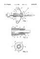
- FIG. 4is a partial cross-sectional view of a bump tubing type of catheter and an alternate form of the strain relief device of the present invention showing the catheter in perspective and the strain relief in cross-section;
- FIG. 5is an enlarged cross-sectional view of the strain relief device of FIG. 4;
- FIG. 6is an enlarged end view of the distal end of the strain relief device shown in FIG. 4;
- FIG. 7is an enlarged end view of the proximal end of the strain relief device shown in FIG. 4;
- FIG. 8is a partial cross-sectional view of the connection between the hub member and catheter tube and an alternate form of the strain relief device of the present invention showing the hub and catheter tube in perspective and the strain relief in cross-section;
- FIG. 9is a partial cross-sectional view of the embodiment shown in FIG. 8 with the hub member and catheter tube removed;
- FIG. 10is a partial cross-sectional view of two different diameter portions of a catheter tube and an alternate form of the strain relief device of the present invention showing the catheter tube in perspective and the strain relief in cross-section.
- a first preferred form of the present inventionis used on a catheter 10 having a hub 12 and catheter tube 14.
- the strain relief device 16is preferably formed by an injection molding process and is formed of a material, such as polyurethane and which has a flexibility that is less than that of the catheter tube 14, yet is greater than or equal to the flexibility of the hub 12.
- the strain relief device 16includes a lumen 18 extending therethrough.
- the lumen 18has a diameter which is sufficient to allow the passage of at least a portion of the catheter tube 14 therethrough to facilitate the assembly thereof.
- the strain relief device 16preferably includes a distal portion 20 and a proximal portion 22 as well as a central portion 24 adjacent to the lumen 18.
- a pair of suture wings 25extend laterally from the external surface of the strain relief device 16.
- the diameter of the distal portion 20 and the proximal portion 22are preferably approximately equal to each other and the outer diameter of the portion of the catheter tube 14 which is intended to receive the strain relief device 16 thereon.
- the diameteris preferably about twenty five percent greater than the diameter of the distal portion 20 or proximal portion 22 adjacent to the lumen 18.
- the lumen 18 adjacent to the distal portion 20includes an outwardly tapered lip 26 extending along the circumference thereof. Additionally, a vent area 28 is formed along the lumen 18 to create a channel for the bonding material to flow into the distal portion.
- the vent area 28may consist of one or more channels which extend the entire length of the distal portion 20 to promote the capillary flow of the bonding material into and along the distal portion 20.
- the presence of at least one vent 28 area on at least one of the distal portion 20 or proximal portion 22is important in the preferred embodiment due to the existence of two bonding areas. Without the vent area 28, it has been found that when either the distal portion 20 or the proximal portion 22 is bonded, air may not be allowed to escape from the opposite end of the strain relief device and the bonding material may not flow consistently into the other of the distal or proximal portion because the opposite end of the strain relief device is effectively sealed. Therefore, it is preferable that at least the portion of the strain relief device 16 which is to be bonded as a later step in the manufacturing process include a vent area 28.
- the proximal portion 22preferably also includes an outwardly tapered lip 30 and a vent area 32 to promote the flow of the bonding material into the proximal portion 22.
- the tapered lip 26 and the vent area 28enable the bonding material to be placed adjacent to the tapered lip 26 on the strain relief device 16 and the bonding material will flow around the lumen of the strain relief device and the around the catheter tube in a preferably uniform and symmetrical manner.
- the vent area 28also facilitates the capillary action of the distal portion so that the air is allowed to flow therefrom and the bonding material is drawn into the distal portion 20 such that the bonding material uniformly flows between the catheter tube and the distal portion.
- the central portion 24 in the strain relief devicehas the largest diameter of the lumen 18 and therefore allows the air to pass therefrom while the capillary forces draw the bonding material into the respective distal or proximal portions.
- the flow of the bonding material into the central portionin inhibited by the increased surface area of the central portion as compared to the surface area of the distal or proximal portion.
- the use of the vent area 28 on the distal portion 20 and the vent area 32 on the proximal portion 22allows the bonding material to flow into the proximal portion 22 when the distal portion 20 has been previously bonded and into the distal portion 20 when the proximal portion 22 has been previously bonded.
- the strain relief device 16 of the present inventionis designed so that the deflection and flexibility characteristics of the strain relief device remain the same or are improved over prior strain relief devices. These characteristics are important in order to avoid abrupt curvature changes, such as kinking of the catheter and to ensure predictable and uniform curvatures adjacent to the strain relief device.
- the strain relief device of the present embodimentalso provides superior pull to separation forces such that the strain relief device having the suture wings of the preferred embodiment thereon will not separate from the catheter tube unless forces which are substantially greater than those forces that are typically encountered during normal catheter use are applied to the suture wing. Similarly, any torsional forces which are typically encountered during typical catheter use are readily overcome by the catheter strain relief device of the present invention.
- the use of the distal portion 20 and proximal portion 22 to form two separate or distinct bonding areaswill provide the user with superior pull to separation forces such that the strain relief device will resist kinking as well as separation of the catheter tube if increased lateral, torsional and/or longitudinal forces are applied to the catheter tube.
- the geometry of the lumen 18is designed to correlate to the viscosity of the bonding material so that the capillary forces resulting from the placement of the bonding material into the tapered lip of the respective portions will pull the bonding material into a complete, even uniform bonding pattern which at least forms a bond having a radially symmetrical surface about the end of the respective portion and which preferably entirely fills and corresponds precisely with the geometry of the lumen along the outer surface of the catheter tube.
- the geometry of the lumen 18may be adjusted depending on the intended viscosity and strength of the bonding material used. For example, when a bonding material such as THF is used, it is anticipated that the diameter of the lumen 18 along the distal portion 20 and proximal portion 22 of the strain relief device 16 will be sized to be about two thousandths of an inch larger than the anticipated diameter of the catheter tube. Therefore, with a catheter of about 2.5 french, the catheter tube will be approximately thirty two thousandths of an inch plus or minus two thousandths of an inch.
- the diameter of the distal portion 20 and the proximal portion 22will be about thirty six thousandths of an inch to ensure that there is always about one or two thousandths of an inch of clearance between the lumen 18 and the catheter tube.
- the diameter of the central portion 24will be about forty-five thousandths of an inch. This spacing will promote the capillary action to allow the bonding material such as THX to flow into the distal portion and proximal portion.
- the length of the distal portion and the proximal portion adjacent to the lumenshould be in the range of about twenty to sixty thousands of an inch to ensure sufficient bond strength.
- the length of the distal portion and proximal portionare preferably limited in order to avoid any negative effect on the deflection and flexibility characteristics of the catheter tube due to the presence of the bond.
- Another limiting feature on the length of the distal portion and the proximal portionis the desire to avoid the entrapment of the solvent in a manner which prevents proper evaporation of the solvents in the bonding material. If the solvents are not properly evaporated, the trapped unevaporated solvents may degrade the catheter tube and/or strain relief device.
- the diameter and length of the distal portion and/or proximal portionare preferably also modified to provide an optimal bonding surface between the catheter tube and/or hub and the interior of the strain relief device.
- an alternate preferred form of the present inventionis used on a catheter 10 having a hub 12 and a bump type of catheter tube 60 wherein the diameter of the catheter tube varies between the proximal and distal portions thereof.
- the strain relief device 50 of this embodimentis preferably formed by an injection molding process and is formed of a material, such as polyurethane and which has a flexibility that is less than that of the catheter tube 60, yet is greater than or equal to the flexibility of the hub 12.
- the strain relief device 50includes a lumen 52 extending therethrough.
- the lumen 52has a minimum diameter which is sufficient to allow the passage of at least a portion of the catheter tube 60 therethrough to facilitate the assembly thereof.
- the strain relief device 50preferably includes a smaller diameter distal portion 54 and a larger diameter proximal portion 56 as well as an even larger diameter central portion 58 adjacent to the lumen 52.
- the diameter of the distal portion 54 and the proximal portion 56are preferably approximately equal to the outer diameter of the portion of the catheter tube 60 which is intended to receive the strain relief device 50 thereon.
- the lumen 52 adjacent to the distal portion 54includes an outwardly tapered lip 62 extending along the circumference thereof.
- a vent area 64is formed along the lumen 52 to create a channel for the bonding material to flow into the distal portion 54.
- the vent area 64may consist of one or more channels which extend longitudinally along the entire lengthwise dimension of the distal portion 54 to promote the capillary flow of the bonding material into and along the distal portion 54.
- vent areaon either the distal portion 54 or proximal portion 56 is important in the present embodiment due to the existence of the two bonding areas along the catheter tube. Without at least one vent area, it has been found that when either the distal portion 54 or the proximal portion 56 is bonded, the bonding material may not flow consistently into the second portion because the opposite end of the strain relief device is sealed and may not allow the air in the lumen to flow therefrom. Therefore, it is preferable that at least the portion of the strain relief device 50 which is to be bonded as a later step in the manufacturing process include a vent area.
- the proximal portion 56preferably also includes an outwardly tapered lip 66 and a proximal vent area 68 to promote the flow of the bonding material into the proximal portion 56.
- the tapered lip 66 and the vent area 68enable the bonding material to be placed adjacent to the tapered lip 66 on the strain relief device 50 and the bonding material will flow around the lumen of the strain relief device 50 and the around the catheter tube 60.
- the proximal vent area 68also facilitates the capillary action of the distal portion so that the bonding material is drawn into the distal portion 54 as the air flows outwardly therefrom so that the bonding material uniformly flows between the catheter tube and the distal portion.
- the central portion 58 in the strain relief devicehas the largest diameter portion of the lumen 52 and therefore allows the capillary forces to draw the bonding material into the respective distal or proximal portions while inhibiting the flow of the bonding material into the central portion. As described above, this is believed to be due at least in part to the differences in the surface area of the distal or proximal areas and the central portion.
- the diameter of the central portionis preferably significantly larger than the diameter of the proximal portion 56.
- vent area 64 on the distal portion 54 and the vent area 68 on the proximal portion 56allows the bonding material to flow into the proximal portion when the distal portion 54 has been previously bonded and into the distal portion when the proximal portion has been previously bonded to the catheter tube and/or hub.
- the strain relief device 50 of this embodimentis designed so that the deflection and flexibility characteristics of the strain relief device remain the same or are improved over prior strain relief devices. These characteristics are important in order to avoid abrupt curvature changes, such as kinking of the catheter and to ensure predictable and uniform curvatures adjacent to the strain relief device.
- the strain relief device of the present embodimentalso provides superior pull to separation forces such that the strain relief device of this embodiment having suture wings similar to those of the preferred embodiment will not separate from the catheter tube unless forces which are substantially greater than those forces that are typically encountered during normal catheter use are applied to the suture wing. It is believed that any such excess forces would overcome the wing portions of the suture wings before the strain relief of the present invention were overcome.
- the present inventionmay also be used in the event that it is desired bond the catheter strain relief device to the hub and catheter tube (FIGS. 8 and 9) or to bond two pieces of catheter tubing having different diameters together at the desired location of the strain relief device 50 (FIG. 10).
- the use of the different diameter distal portion 54 and proximal portion 56 to form two bonding areaswill provide the user with superior pull to separation forces such that the strain relief device will resist kinking due to various torsional forces as well as resistance to the separation of the separate sections of catheter tube if increased lateral, torsional and/or longitudinal forces are applied to the catheter tube.
- the geometry of the lumen 52is designed to correlate to the viscosity of the bonding material so that the capillary forces resulting from the placement of the bonding material into the tapered of the respective portions will pull the bonding material into a complete, even uniform bonding pattern which at least forms a bond having a radially symmetrical surface about the end of the respective portion and which preferably entirely fills and corresponds precisely with the geometry of the lumen along the catheter tube.
- the geometry of the lumen 50 of this embodimentmay also need to be adjusted according to the viscosity and strength of the bonding material used.
- a bonding materialsuch as THF
- the diameter of the lumen 52 along the distal portion 54 and proximal portion 56 of the strain relief device 50will be sized to be about two thousandths of an inch larger than the anticipated diameter of the adjacent portion of the catheter tube. Therefore, with a catheter tube having a distal segment of about 2.5 french, the diameter of the distal segment of the catheter tube will be approximately thirty two thousandths of an inch plus or minus two thousandths of an inch.
- the diameter of the distal portion 54 of the strain relief devicewill be about thirty six thousandths of an inch to ensure that there is always about one or two thousandths of an inch of clearance between the lumen 52 and the distal segment of the catheter tube.
- the catheter tubealso has a proximal segment of about 5 french and the diameter of the proximal segment of the catheter tube will be approximately sixty five thousandths of an inch plus or minus two thousandths of an inch.
- the diameter of the proximal portion 56 of the strain relief device 50will be about sixty eight thousandths of an inch to ensure that there is always about one or two thousandths of an inch of clearance between the lumen 52 and the proximal segment of the catheter tube.
- the diameter of the central portion 58will preferably be about seventy five thousandths of an inch. This spacing will promote the capillary action to allow the bonding material such as THX to flow into the distal portion and proximal portions of the strain relief device 50.
- the length of the distal portion and the proximal portion adjacent to the lumenshould be in the range of about twenty to sixty thousands of an inch to ensure sufficient bond strength.
- the length of the distal portion and proximal portionare preferably limited in order to avoid any negative effect on the deflection and flexibility characteristics of the catheter tube due to the presence of the bond.
- Another limiting feature on the length of the distal portion and the proximal portionis the desire to avoid the entrapment of the solvent in a manner which prevents proper evaporation of the solvents in the bonding material. If the solvents are not properly evaporated, the trapped unevaporated solvents may degrade the catheter tube and/or strain relief device. Therefore, as the diameter of the catheter tube and bonding material that are to be used is changed, the diameter and length of the distal portion and/or proximal portion must also be modified to provide the optimal bonding surface.
- the embodiment illustrated in FIG. 8includes an additional intermediate portion 70 which has a diameter which is greater than the diameter of the lumen 72 adjacent to the distal portion 74, proximal portion 76 and the central portion 78.
- the intermediate portion 70forms an enlarged diameter area which inhibits the flow of bonding material inwardly beyond the proximal portion 76.
- the central portion 78has a diameter which gradually increases from the distal portion 74 towards the intermediate portion 70 and is in between the diameters of the distal portion 74 and the proximal portion 76.
- the strain relief device 80includes a pair of vent areas 82 and 84, respectively, which extend longitudinally along the interior of the distal portion 74 and proximal portion 76.
- the function of this embodiment of the present inventionis substantially similar to the embodiments described above and, therefore, will not be separately referred to herein.
- the embodiment illustrated in FIG. 10includes a preferably transparent or semi-transparent window 90 as an additional feature which may be readily incorporated into the embodiments of the strain relief devices described above.
- the windowpreferably is located on a section of the central portion 78 which has a lumen diameter that is greater than the diameter of the lumen 72 adjacent to the distal portion 74 or proximal portion 76.
- the window 90is preferably in fluid flow communication with at least one inner lumen of the catheter tube although it is anticipated that the window 90 may be partitioned (not shown) or otherwise modified to enable the user to observe the flow of fluids through one or more lumens of the catheter.
- the function of this embodiment of the present inventionis substantially similar to the embodiments described above and, therefore, will not be separately referred to herein.
Landscapes
- Health & Medical Sciences (AREA)
- Life Sciences & Earth Sciences (AREA)
- Biophysics (AREA)
- Pulmonology (AREA)
- Engineering & Computer Science (AREA)
- Anesthesiology (AREA)
- Biomedical Technology (AREA)
- Heart & Thoracic Surgery (AREA)
- Hematology (AREA)
- Animal Behavior & Ethology (AREA)
- General Health & Medical Sciences (AREA)
- Public Health (AREA)
- Veterinary Medicine (AREA)
- Media Introduction/Drainage Providing Device (AREA)
Abstract
Description
Claims (21)
Priority Applications (3)
| Application Number | Priority Date | Filing Date | Title |
|---|---|---|---|
| US09/036,498US6074379A (en) | 1998-03-06 | 1998-03-06 | Catheter strain relief device |
| AU31824/99AAU3182499A (en) | 1998-03-06 | 1999-03-03 | Catheter strain relief device |
| PCT/US1999/004749WO1999044654A1 (en) | 1998-03-06 | 1999-03-03 | Catheter strain relief device |
Applications Claiming Priority (1)
| Application Number | Priority Date | Filing Date | Title |
|---|---|---|---|
| US09/036,498US6074379A (en) | 1998-03-06 | 1998-03-06 | Catheter strain relief device |
Publications (1)
| Publication Number | Publication Date |
|---|---|
| US6074379Atrue US6074379A (en) | 2000-06-13 |
Family
ID=21888912
Family Applications (1)
| Application Number | Title | Priority Date | Filing Date |
|---|---|---|---|
| US09/036,498Expired - Fee RelatedUS6074379A (en) | 1998-03-06 | 1998-03-06 | Catheter strain relief device |
Country Status (3)
| Country | Link |
|---|---|
| US (1) | US6074379A (en) |
| AU (1) | AU3182499A (en) |
| WO (1) | WO1999044654A1 (en) |
Cited By (69)
| Publication number | Priority date | Publication date | Assignee | Title |
|---|---|---|---|---|
| US6231548B1 (en)* | 1999-08-26 | 2001-05-15 | Alfred Ernest Bassett | Securing device for intravenous cannula or catheter |
| US6332874B1 (en) | 1998-08-28 | 2001-12-25 | C.R. Bard, Inc. | Coupling and stabilization system for proximal end of catheter |
| US6524278B1 (en) | 1998-09-04 | 2003-02-25 | Nmt Group Plc | Needle sheath |
| US6575959B1 (en) | 1999-12-27 | 2003-06-10 | Scimed Life Systems, Inc. | Catheter incorporating an insert molded hub and method of manufacturing |
| US20050253389A1 (en)* | 2004-05-13 | 2005-11-17 | Schulte Gregory T | Medical tubing connector assembly incorporating strain relief sleeve |
| US20050283134A1 (en)* | 2004-06-22 | 2005-12-22 | Scimed Life Systems, Inc. | Catheter shaft with improved manifold bond |
| US20060015086A1 (en)* | 2004-04-01 | 2006-01-19 | Kelly Rasmussen | Catheter connector system |
| US20060200201A1 (en)* | 2005-02-16 | 2006-09-07 | Transoma Medical, Inc. | Implantable housing with catheter strain relief |
| US20060264814A1 (en)* | 2005-05-20 | 2006-11-23 | Medtronic, Inc. | Locking catheter connector and method |
| US20060264911A1 (en)* | 2005-05-20 | 2006-11-23 | Medtronic, Inc. | Squeeze-actuated catheter connector and method |
| US7537245B2 (en) | 2005-02-14 | 2009-05-26 | Medtronic, Inc. | Strain relief device and connector assemblies incorporating same |
| US20090157007A1 (en)* | 2007-12-18 | 2009-06-18 | Becton, Dickinson And Company | Anti-occlusion catheter adapter |
| US20090192496A1 (en)* | 2008-01-30 | 2009-07-30 | Becton, Dickinson And Company | Occlusion resistant catheters |
| US7854731B2 (en) | 2004-03-18 | 2010-12-21 | C. R. Bard, Inc. | Valved catheter |
| US7875019B2 (en) | 2005-06-20 | 2011-01-25 | C. R. Bard, Inc. | Connection system for multi-lumen catheter |
| US7883502B2 (en) | 2004-03-18 | 2011-02-08 | C. R. Bard, Inc. | Connector system for a proximally trimmable catheter |
| US8083728B2 (en) | 2004-03-18 | 2011-12-27 | C. R. Bard, Inc. | Multifunction adaptor for an open-ended catheter |
| US8177771B2 (en) | 2004-03-18 | 2012-05-15 | C. R. Bard, Inc. | Catheter connector |
| US8337484B2 (en) | 2009-06-26 | 2012-12-25 | C. R. Band, Inc. | Proximally trimmable catheter including pre-attached bifurcation and related methods |
| WO2013043671A1 (en)* | 2011-09-22 | 2013-03-28 | Medtronic, Inc. | Delivery system assembly with an inner member having a flared distal end |
| US20140039400A1 (en)* | 2007-12-07 | 2014-02-06 | Pyng Medical Corp. | Apparatus and methods for introducing portals in bone |
| USD715929S1 (en) | 2013-11-26 | 2014-10-21 | Kimberly-Clark Worldwide, Inc. | Catheter strain relief clip |
| US8974421B1 (en) | 2013-11-26 | 2015-03-10 | Avent, Inc. | Catheter strain relief clip |
| WO2017127074A1 (en)* | 2016-01-20 | 2017-07-27 | C.R. Bard, Inc. | Access port and catheter assembly including catheter distal portion stability features |
| US9759359B2 (en) | 2016-01-26 | 2017-09-12 | Tectran Mfg. Inc. | Grip and fitting assemblies and kits utilizing the same |
| US9789279B2 (en) | 2014-04-23 | 2017-10-17 | Becton, Dickinson And Company | Antimicrobial obturator for use with vascular access devices |
| US9808629B2 (en) | 2011-10-24 | 2017-11-07 | Medtronic, Inc. | Delivery system assemblies and associated methods for implantable medical devices |
| US9869416B2 (en) | 2016-01-26 | 2018-01-16 | Tectran Mfg. Inc. | Swivel coupling and hose assemblies and kits utilizing the same |
| US9867982B2 (en) | 2011-11-17 | 2018-01-16 | Medtronic, Inc. | Delivery system assemblies and associated methods for implantable medical devices |
| US9913960B2 (en) | 2010-08-12 | 2018-03-13 | C. R. Bard, Inc. | Trimmable catheter including distal portion stability features |
| US9956379B2 (en) | 2014-04-23 | 2018-05-01 | Becton, Dickinson And Company | Catheter tubing with extraluminal antimicrobial coating |
| US10124175B2 (en) | 2011-11-17 | 2018-11-13 | Medtronic, Inc. | Delivery system assemblies for implantable medical devices |
| US10232088B2 (en) | 2014-07-08 | 2019-03-19 | Becton, Dickinson And Company | Antimicrobial coating forming kink resistant feature on a vascular access device |
| US10238833B2 (en) | 2010-08-12 | 2019-03-26 | C. R. Bard, Inc. | Access port and catheter assembly including catheter distal portion stability features |
| US10376686B2 (en) | 2014-04-23 | 2019-08-13 | Becton, Dickinson And Company | Antimicrobial caps for medical connectors |
| US10413702B2 (en) | 2011-10-21 | 2019-09-17 | Boston Scientific Scimed, Inc. | Locking catheter hub |
| US10493244B2 (en) | 2015-10-28 | 2019-12-03 | Becton, Dickinson And Company | Extension tubing strain relief |
| US20210113810A1 (en)* | 2019-10-22 | 2021-04-22 | Bard Access Systems, Inc. | Rapidly Insertable Central Catheter and Methods Thereof |
| CN112704803A (en)* | 2019-10-27 | 2021-04-27 | 巴德阿克塞斯系统股份有限公司 | Rapidly insertable central catheter and method |
| US11357962B2 (en) | 2013-02-13 | 2022-06-14 | Becton, Dickinson And Company | Blood control IV catheter with stationary septum activator |
| US11471647B2 (en) | 2014-11-07 | 2022-10-18 | C. R. Bard, Inc. | Connection system for tunneled catheters |
| US11617861B2 (en) | 2014-06-17 | 2023-04-04 | St. Jude Medical, Cardiology Division, Inc. | Triple coil catheter support |
| US11622806B2 (en) | 2010-04-09 | 2023-04-11 | St Jude Medical International Holding S.À R.L. | Control handle for a contact force ablation catheter |
| US11642063B2 (en) | 2018-08-23 | 2023-05-09 | St. Jude Medical, Cardiology Division, Inc. | Curved high density electrode mapping catheter |
| US11642064B2 (en) | 2015-10-21 | 2023-05-09 | St. Jude Medical, Cardiology Division, Inc. | High density electrode mapping catheter |
| US11647935B2 (en) | 2017-07-24 | 2023-05-16 | St. Jude Medical, Cardiology Division, Inc. | Masked ring electrodes |
| US11666729B2 (en) | 2017-11-03 | 2023-06-06 | Hollister Incorporated | Methods of bonding components to polymeric substrates |
| US11672947B2 (en) | 2017-11-28 | 2023-06-13 | St. Jude Medical, Cardiology Division, Inc. | Lumen management catheter |
| US11696716B2 (en) | 2008-12-29 | 2023-07-11 | St. Jude Medical, Atrial Fibrillation Division, Inc. | Non-contact electrode basket catheters with irrigation |
| US11707229B2 (en) | 2015-05-08 | 2023-07-25 | St Jude Medical International Holding S.À R.L. | Integrated sensors for medical devices and method of making integrated sensors for medical devices |
| US11786705B2 (en) | 2016-10-24 | 2023-10-17 | St. Jude Medical, Cardiology Division, Inc. | Catheter insertion devices |
| US11826172B2 (en) | 2014-05-06 | 2023-11-28 | St. Jude Medical, Cardiology Division, Inc. | Electrode support structure assembly |
| US11839424B2 (en) | 2010-05-05 | 2023-12-12 | St. Jude Medical, Atrial Fibrillation Division, Inc | Monitoring, managing and/or protecting system and method for non-targeted tissue |
| US11844910B2 (en) | 2014-06-05 | 2023-12-19 | St. Jude Medical, Cardiology Division, Inc. | Deflectable catheter shaft section |
| US11896284B2 (en) | 2007-12-28 | 2024-02-13 | St. Jude Medical, Atrial Fibrillation Division, Inc | System and method for measurement of an impedance using a catheter such as an ablation catheter |
| US11896782B2 (en) | 2017-08-23 | 2024-02-13 | C. R. Bard, Inc. | Priming and tunneling system for a retrograde catheter assembly |
| US11918762B2 (en) | 2018-10-03 | 2024-03-05 | St. Jude Medical, Cardiology Division, Inc. | Reduced actuation force electrophysiology catheter handle |
| US12011549B2 (en) | 2017-01-19 | 2024-06-18 | St. Jude Medical, Cardiology Division, Inc. | Sheath visualization |
| US12036027B2 (en) | 2016-10-28 | 2024-07-16 | St. Jude Medical, Cardiology Division, Inc. | Flexible high-density mapping catheter |
| US12048545B2 (en) | 2014-10-27 | 2024-07-30 | St. Jude Medical, Cardiology Division, Inc. | Apparatus and method for connecting elements in medical devices |
| US12076079B2 (en) | 2016-05-03 | 2024-09-03 | St. Jude Medical, Cardiology Division, Inc. | Irrigated high density electrode catheter |
| US12082936B2 (en) | 2018-09-27 | 2024-09-10 | St. Jude Medical, Cardiology Division, Inc. | Uniform mapping balloon |
| US12121357B2 (en) | 2015-10-21 | 2024-10-22 | St. Jude Medical, Cardiology Division, Inc. | High density electrode mapping catheter |
| US12156979B2 (en) | 2018-05-21 | 2024-12-03 | St. Jude Medical, Cardiology Division, Inc. | Deflectable catheter shaft with pullwire anchor feature |
| US12263338B2 (en) | 2013-01-16 | 2025-04-01 | St. Jude Medical, Cardiology Division, Inc. | Flexible high-density mapping catheter tips and flexible ablation catheter tips with onboard high-density mapping electrodes |
| US12263014B2 (en) | 2020-08-18 | 2025-04-01 | St. Jude Medical, Cardiology Division, Inc. | High-density electrode catheters with magnetic position tracking |
| US12295649B2 (en) | 2010-12-02 | 2025-05-13 | St. Jude Medical, Atrial Fibrillation Division, Inc. | Catheter electrode assemblies and methods of construction thereof |
| US12376901B2 (en) | 2018-05-21 | 2025-08-05 | St. Jude Medical, Cardiology Division, Inc. | Radio-frequency ablation and direct current electroporation catheters |
| US12383333B2 (en) | 2015-01-28 | 2025-08-12 | St. Jude Medical, Cardiology Division, Inc. | Thermal mapping catheter |
Families Citing this family (2)
| Publication number | Priority date | Publication date | Assignee | Title |
|---|---|---|---|---|
| US10806901B2 (en) | 2015-10-28 | 2020-10-20 | Becton, Dickinson And Company | Catheter adapter with distal inner diameter curvature providing kink resistance |
| AU2017312325B2 (en) | 2016-08-19 | 2022-11-17 | B. Braun Melsungen Ag | Needle assemblies and related methods |
Citations (30)
| Publication number | Priority date | Publication date | Assignee | Title |
|---|---|---|---|---|
| FR1125735A (en)* | 1954-06-16 | 1956-11-06 | Heart probe and method of manufacturing this probe | |
| US3097646A (en)* | 1960-12-06 | 1963-07-16 | Abbott Lab | Venous catheter apparatus |
| US3191655A (en)* | 1963-03-21 | 1965-06-29 | Us Rubber Co | Molded article, especially a tubeless tire valve stem assembly |
| US3469579A (en)* | 1967-05-05 | 1969-09-30 | Becton Dickinson Co | Catheter needle |
| FR2033068A5 (en)* | 1969-02-25 | 1970-11-27 | Plastifiber | Moulded pipe coupling seals |
| US3720210A (en)* | 1971-03-03 | 1973-03-13 | Baxter Laboratories Inc | Indwelling catheter device |
| US3721231A (en)* | 1971-02-01 | 1973-03-20 | Becton Dickinson Co | Catheter for high pressure injections |
| US3802433A (en)* | 1971-09-14 | 1974-04-09 | C Raven | Infusion cannula assemblies |
| US3861972A (en)* | 1970-08-24 | 1975-01-21 | Johnson & Johnson | Intravenous catheter |
| US4191185A (en)* | 1977-09-06 | 1980-03-04 | Johnson & Johnson | Catheter assembly |
| US4211741A (en)* | 1977-04-07 | 1980-07-08 | Sunlite Plastics, Inc. | Extrusion process for laminated medical-surgical tubing |
| US4292970A (en)* | 1980-01-24 | 1981-10-06 | Hession Jr William M | Apparatus for intravenous catheter starter |
| US4354495A (en)* | 1980-10-30 | 1982-10-19 | Sherwood Medical Industries Inc. | Method of connecting plastic tube to a plastic part |
| US4389210A (en)* | 1978-08-21 | 1983-06-21 | Abbott Laboratories | Catheter placement assembly having axial and rotational alignment means |
| US4391029A (en)* | 1978-12-18 | 1983-07-05 | Baxter Travenol Laboratories Inc. | Catheter hub assembly |
| EP0168289A1 (en)* | 1984-06-07 | 1986-01-15 | Argon Medical Corp. | Flexible collar support |
| US4592749A (en)* | 1984-06-22 | 1986-06-03 | Gish Biomedical, Inc. | Catheter system |
| US4610674A (en)* | 1984-09-13 | 1986-09-09 | Terumo Kabushi Kaisha | Catheter introducing instrument |
| US4776849A (en)* | 1984-11-06 | 1988-10-11 | Terumo Kabushiki Kaisha | Medical instrument |
| US4781703A (en)* | 1985-10-17 | 1988-11-01 | Menlo Care, Inc. | Catheter assembly |
| US4806182A (en)* | 1985-10-15 | 1989-02-21 | Schneider-Shiley (U.S.A.) Inc. | Method of bonding a hub to a Teflon-lined catheter body |
| US4840622A (en)* | 1987-10-06 | 1989-06-20 | Menlo Care, Inc. | Kink resistant catheter |
| US4846812A (en)* | 1988-03-22 | 1989-07-11 | Menlo Care, Inc. | Softening catheter |
| EP0368377A1 (en)* | 1988-10-19 | 1990-05-16 | Klaas Dijkstra | Implantable injection chamber device |
| US4966588A (en)* | 1986-07-25 | 1990-10-30 | H. G. Wallace Limited | Device suitable for the administration of a therapeutic substance |
| US4991629A (en)* | 1987-09-25 | 1991-02-12 | Industrie Borla S.P.A. | Gas-tight closure device for the connecting ends of tubes for biomedical fluid-transporting apparatus, particularly haemodialysis lines, which are sterilized by means of sterilizing gas |
| EP0434324A1 (en)* | 1989-12-18 | 1991-06-26 | Critikon, Inc. | Catheter assemblies for prevention of blood leakage |
| US5041097A (en)* | 1990-02-26 | 1991-08-20 | Johnson Gerald W | Intravenous catheter fitting with protective end seal |
| US5167647A (en)* | 1989-09-14 | 1992-12-01 | Cordis Corporation | Catheter with a strain relief member |
| US5330449A (en)* | 1991-01-17 | 1994-07-19 | Sherwood Medical Company | Catheter strain relief device |
- 1998
- 1998-03-06USUS09/036,498patent/US6074379A/ennot_activeExpired - Fee Related
- 1999
- 1999-03-03AUAU31824/99Apatent/AU3182499A/ennot_activeWithdrawn
- 1999-03-03WOPCT/US1999/004749patent/WO1999044654A1/enactiveApplication Filing
Patent Citations (31)
| Publication number | Priority date | Publication date | Assignee | Title |
|---|---|---|---|---|
| FR1125735A (en)* | 1954-06-16 | 1956-11-06 | Heart probe and method of manufacturing this probe | |
| US3097646A (en)* | 1960-12-06 | 1963-07-16 | Abbott Lab | Venous catheter apparatus |
| US3191655A (en)* | 1963-03-21 | 1965-06-29 | Us Rubber Co | Molded article, especially a tubeless tire valve stem assembly |
| US3469579A (en)* | 1967-05-05 | 1969-09-30 | Becton Dickinson Co | Catheter needle |
| FR2033068A5 (en)* | 1969-02-25 | 1970-11-27 | Plastifiber | Moulded pipe coupling seals |
| US3861972A (en)* | 1970-08-24 | 1975-01-21 | Johnson & Johnson | Intravenous catheter |
| US3721231A (en)* | 1971-02-01 | 1973-03-20 | Becton Dickinson Co | Catheter for high pressure injections |
| US3720210A (en)* | 1971-03-03 | 1973-03-13 | Baxter Laboratories Inc | Indwelling catheter device |
| US3802433A (en)* | 1971-09-14 | 1974-04-09 | C Raven | Infusion cannula assemblies |
| US4211741A (en)* | 1977-04-07 | 1980-07-08 | Sunlite Plastics, Inc. | Extrusion process for laminated medical-surgical tubing |
| US4191185A (en)* | 1977-09-06 | 1980-03-04 | Johnson & Johnson | Catheter assembly |
| US4389210A (en)* | 1978-08-21 | 1983-06-21 | Abbott Laboratories | Catheter placement assembly having axial and rotational alignment means |
| US4391029A (en)* | 1978-12-18 | 1983-07-05 | Baxter Travenol Laboratories Inc. | Catheter hub assembly |
| US4292970A (en)* | 1980-01-24 | 1981-10-06 | Hession Jr William M | Apparatus for intravenous catheter starter |
| US4354495A (en)* | 1980-10-30 | 1982-10-19 | Sherwood Medical Industries Inc. | Method of connecting plastic tube to a plastic part |
| EP0168289A1 (en)* | 1984-06-07 | 1986-01-15 | Argon Medical Corp. | Flexible collar support |
| US4592749A (en)* | 1984-06-22 | 1986-06-03 | Gish Biomedical, Inc. | Catheter system |
| US4610674A (en)* | 1984-09-13 | 1986-09-09 | Terumo Kabushi Kaisha | Catheter introducing instrument |
| US4776849A (en)* | 1984-11-06 | 1988-10-11 | Terumo Kabushiki Kaisha | Medical instrument |
| US4806182A (en)* | 1985-10-15 | 1989-02-21 | Schneider-Shiley (U.S.A.) Inc. | Method of bonding a hub to a Teflon-lined catheter body |
| US4781703A (en)* | 1985-10-17 | 1988-11-01 | Menlo Care, Inc. | Catheter assembly |
| US4966588A (en)* | 1986-07-25 | 1990-10-30 | H. G. Wallace Limited | Device suitable for the administration of a therapeutic substance |
| US4991629A (en)* | 1987-09-25 | 1991-02-12 | Industrie Borla S.P.A. | Gas-tight closure device for the connecting ends of tubes for biomedical fluid-transporting apparatus, particularly haemodialysis lines, which are sterilized by means of sterilizing gas |
| US4840622A (en)* | 1987-10-06 | 1989-06-20 | Menlo Care, Inc. | Kink resistant catheter |
| US4846812A (en)* | 1988-03-22 | 1989-07-11 | Menlo Care, Inc. | Softening catheter |
| EP0368377A1 (en)* | 1988-10-19 | 1990-05-16 | Klaas Dijkstra | Implantable injection chamber device |
| US5167647A (en)* | 1989-09-14 | 1992-12-01 | Cordis Corporation | Catheter with a strain relief member |
| EP0434324A1 (en)* | 1989-12-18 | 1991-06-26 | Critikon, Inc. | Catheter assemblies for prevention of blood leakage |
| US5030205A (en)* | 1989-12-18 | 1991-07-09 | Critikon, Inc. | Catheter assemblies for prevention of blood leakage |
| US5041097A (en)* | 1990-02-26 | 1991-08-20 | Johnson Gerald W | Intravenous catheter fitting with protective end seal |
| US5330449A (en)* | 1991-01-17 | 1994-07-19 | Sherwood Medical Company | Catheter strain relief device |
Cited By (107)
| Publication number | Priority date | Publication date | Assignee | Title |
|---|---|---|---|---|
| US6332874B1 (en) | 1998-08-28 | 2001-12-25 | C.R. Bard, Inc. | Coupling and stabilization system for proximal end of catheter |
| US6524278B1 (en) | 1998-09-04 | 2003-02-25 | Nmt Group Plc | Needle sheath |
| US6231548B1 (en)* | 1999-08-26 | 2001-05-15 | Alfred Ernest Bassett | Securing device for intravenous cannula or catheter |
| US6575959B1 (en) | 1999-12-27 | 2003-06-10 | Scimed Life Systems, Inc. | Catheter incorporating an insert molded hub and method of manufacturing |
| US7854731B2 (en) | 2004-03-18 | 2010-12-21 | C. R. Bard, Inc. | Valved catheter |
| US7883502B2 (en) | 2004-03-18 | 2011-02-08 | C. R. Bard, Inc. | Connector system for a proximally trimmable catheter |
| US8083728B2 (en) | 2004-03-18 | 2011-12-27 | C. R. Bard, Inc. | Multifunction adaptor for an open-ended catheter |
| US8523840B2 (en) | 2004-03-18 | 2013-09-03 | C. R. Bard, Inc. | Connector system for a proximally trimmable catheter |
| US8177771B2 (en) | 2004-03-18 | 2012-05-15 | C. R. Bard, Inc. | Catheter connector |
| US7377915B2 (en) | 2004-04-01 | 2008-05-27 | C. R. Bard, Inc. | Catheter connector system |
| US8177770B2 (en) | 2004-04-01 | 2012-05-15 | C. R. Bard, Inc. | Catheter connector system |
| US20060015086A1 (en)* | 2004-04-01 | 2006-01-19 | Kelly Rasmussen | Catheter connector system |
| US20080200901A1 (en)* | 2004-04-01 | 2008-08-21 | C. R. Bard, Inc. | Catheter connector system |
| US7331613B2 (en) | 2004-05-13 | 2008-02-19 | Medtronic, Inc. | Medical tubing connector assembly incorporating strain relief sleeve |
| US20080103476A1 (en)* | 2004-05-13 | 2008-05-01 | Medtronic, Inc. | Medical tubing connector assembly incorporating strain relief sleeve |
| US20050253389A1 (en)* | 2004-05-13 | 2005-11-17 | Schulte Gregory T | Medical tubing connector assembly incorporating strain relief sleeve |
| US20100145311A1 (en)* | 2004-06-22 | 2010-06-10 | Boston Scientific Scimed, Inc. | Catheter shaft with improved manifold bond |
| US8257343B2 (en) | 2004-06-22 | 2012-09-04 | Boston Scientific Scimed, Inc | Catheter shaft with improved manifold bond |
| US7662144B2 (en) | 2004-06-22 | 2010-02-16 | Boston Scientific Scimed, Inc. | Catheter shaft with improved manifold bond |
| US9238121B2 (en) | 2004-06-22 | 2016-01-19 | Boston Scientific Scimed, Inc. | Catheter shaft with improved manifold bond |
| US20050283134A1 (en)* | 2004-06-22 | 2005-12-22 | Scimed Life Systems, Inc. | Catheter shaft with improved manifold bond |
| US8858529B2 (en) | 2004-06-22 | 2014-10-14 | Boston Scientific Scimed, Inc. | Catheter shaft with improved manifold bond |
| US7537245B2 (en) | 2005-02-14 | 2009-05-26 | Medtronic, Inc. | Strain relief device and connector assemblies incorporating same |
| US20060200201A1 (en)* | 2005-02-16 | 2006-09-07 | Transoma Medical, Inc. | Implantable housing with catheter strain relief |
| US7678101B2 (en) | 2005-05-20 | 2010-03-16 | Medtronic, Inc. | Locking catheter connector and connection system |
| US7387624B2 (en) | 2005-05-20 | 2008-06-17 | Medtronic, Inc. | Squeeze-actuated catheter connecter and method |
| US20060264911A1 (en)* | 2005-05-20 | 2006-11-23 | Medtronic, Inc. | Squeeze-actuated catheter connector and method |
| US20060264814A1 (en)* | 2005-05-20 | 2006-11-23 | Medtronic, Inc. | Locking catheter connector and method |
| US8852168B2 (en) | 2005-06-20 | 2014-10-07 | C. R. Bard, Inc. | Connection system for multi-lumen catheter |
| US7875019B2 (en) | 2005-06-20 | 2011-01-25 | C. R. Bard, Inc. | Connection system for multi-lumen catheter |
| US8206376B2 (en) | 2005-06-20 | 2012-06-26 | C. R. Bard, Inc. | Connection system for multi-lumen catheter |
| US8617138B2 (en) | 2005-06-20 | 2013-12-31 | C. R. Bard, Inc. | Connection system for multi-lumen catheter |
| US9480483B2 (en)* | 2007-12-07 | 2016-11-01 | Pyng Medical Corp. | Apparatus and methods for introducing portals in bone |
| US9724106B2 (en)* | 2007-12-07 | 2017-08-08 | Pyng Medical Corp. | Apparatus and methods for introducing portals in bone |
| US20140039400A1 (en)* | 2007-12-07 | 2014-02-06 | Pyng Medical Corp. | Apparatus and methods for introducing portals in bone |
| US10722247B2 (en)* | 2007-12-07 | 2020-07-28 | Pyng Medical Corp. | Apparatus and methods for introducing portals in bone |
| US20090157007A1 (en)* | 2007-12-18 | 2009-06-18 | Becton, Dickinson And Company | Anti-occlusion catheter adapter |
| US10232140B2 (en) | 2007-12-18 | 2019-03-19 | Becton, Dickinson And Company | Anti-occlusion catheter adapter |
| US11896284B2 (en) | 2007-12-28 | 2024-02-13 | St. Jude Medical, Atrial Fibrillation Division, Inc | System and method for measurement of an impedance using a catheter such as an ablation catheter |
| US20090192496A1 (en)* | 2008-01-30 | 2009-07-30 | Becton, Dickinson And Company | Occlusion resistant catheters |
| US8353876B2 (en)* | 2008-01-30 | 2013-01-15 | Becton, Dickinson And Company | Occlusion resistant catheters |
| US11696716B2 (en) | 2008-12-29 | 2023-07-11 | St. Jude Medical, Atrial Fibrillation Division, Inc. | Non-contact electrode basket catheters with irrigation |
| US8337484B2 (en) | 2009-06-26 | 2012-12-25 | C. R. Band, Inc. | Proximally trimmable catheter including pre-attached bifurcation and related methods |
| US11622806B2 (en) | 2010-04-09 | 2023-04-11 | St Jude Medical International Holding S.À R.L. | Control handle for a contact force ablation catheter |
| US11839424B2 (en) | 2010-05-05 | 2023-12-12 | St. Jude Medical, Atrial Fibrillation Division, Inc | Monitoring, managing and/or protecting system and method for non-targeted tissue |
| US9913960B2 (en) | 2010-08-12 | 2018-03-13 | C. R. Bard, Inc. | Trimmable catheter including distal portion stability features |
| US10905850B2 (en) | 2010-08-12 | 2021-02-02 | C. R. Bard, Inc. | Access port and catheter assembly including catheter distal portion stability features |
| US10238833B2 (en) | 2010-08-12 | 2019-03-26 | C. R. Bard, Inc. | Access port and catheter assembly including catheter distal portion stability features |
| US11786697B2 (en) | 2010-08-12 | 2023-10-17 | C. R. Bard, Inc. | Access port and catheter assembly including catheter distal portion stability features |
| US12295649B2 (en) | 2010-12-02 | 2025-05-13 | St. Jude Medical, Atrial Fibrillation Division, Inc. | Catheter electrode assemblies and methods of construction thereof |
| US8945145B2 (en) | 2011-09-22 | 2015-02-03 | Medtronic, Inc. | Delivery system assemblies for implantable medical devices |
| WO2013043671A1 (en)* | 2011-09-22 | 2013-03-28 | Medtronic, Inc. | Delivery system assembly with an inner member having a flared distal end |
| US10413702B2 (en) | 2011-10-21 | 2019-09-17 | Boston Scientific Scimed, Inc. | Locking catheter hub |
| US9808629B2 (en) | 2011-10-24 | 2017-11-07 | Medtronic, Inc. | Delivery system assemblies and associated methods for implantable medical devices |
| US9867982B2 (en) | 2011-11-17 | 2018-01-16 | Medtronic, Inc. | Delivery system assemblies and associated methods for implantable medical devices |
| US10124175B2 (en) | 2011-11-17 | 2018-11-13 | Medtronic, Inc. | Delivery system assemblies for implantable medical devices |
| US12263338B2 (en) | 2013-01-16 | 2025-04-01 | St. Jude Medical, Cardiology Division, Inc. | Flexible high-density mapping catheter tips and flexible ablation catheter tips with onboard high-density mapping electrodes |
| US11357962B2 (en) | 2013-02-13 | 2022-06-14 | Becton, Dickinson And Company | Blood control IV catheter with stationary septum activator |
| US8974421B1 (en) | 2013-11-26 | 2015-03-10 | Avent, Inc. | Catheter strain relief clip |
| USD715929S1 (en) | 2013-11-26 | 2014-10-21 | Kimberly-Clark Worldwide, Inc. | Catheter strain relief clip |
| US9248260B2 (en) | 2013-11-26 | 2016-02-02 | Avent, Inc. | Catheter strain relief clip |
| WO2015079333A1 (en) | 2013-11-26 | 2015-06-04 | Avent, Inc. | Catheter strain relief clip |
| US9956379B2 (en) | 2014-04-23 | 2018-05-01 | Becton, Dickinson And Company | Catheter tubing with extraluminal antimicrobial coating |
| US9789279B2 (en) | 2014-04-23 | 2017-10-17 | Becton, Dickinson And Company | Antimicrobial obturator for use with vascular access devices |
| US10589063B2 (en) | 2014-04-23 | 2020-03-17 | Becton, Dickinson And Company | Antimicrobial obturator for use with vascular access devices |
| US10376686B2 (en) | 2014-04-23 | 2019-08-13 | Becton, Dickinson And Company | Antimicrobial caps for medical connectors |
| US11357965B2 (en) | 2014-04-23 | 2022-06-14 | Becton, Dickinson And Company | Antimicrobial caps for medical connectors |
| US11826172B2 (en) | 2014-05-06 | 2023-11-28 | St. Jude Medical, Cardiology Division, Inc. | Electrode support structure assembly |
| US11844910B2 (en) | 2014-06-05 | 2023-12-19 | St. Jude Medical, Cardiology Division, Inc. | Deflectable catheter shaft section |
| US11617861B2 (en) | 2014-06-17 | 2023-04-04 | St. Jude Medical, Cardiology Division, Inc. | Triple coil catheter support |
| US11219705B2 (en) | 2014-07-08 | 2022-01-11 | Becton, Dickinson And Company | Antimicrobial coating forming kink resistant feature on a vascular access device |
| US10232088B2 (en) | 2014-07-08 | 2019-03-19 | Becton, Dickinson And Company | Antimicrobial coating forming kink resistant feature on a vascular access device |
| US12048545B2 (en) | 2014-10-27 | 2024-07-30 | St. Jude Medical, Cardiology Division, Inc. | Apparatus and method for connecting elements in medical devices |
| US11471647B2 (en) | 2014-11-07 | 2022-10-18 | C. R. Bard, Inc. | Connection system for tunneled catheters |
| US12383333B2 (en) | 2015-01-28 | 2025-08-12 | St. Jude Medical, Cardiology Division, Inc. | Thermal mapping catheter |
| US11707229B2 (en) | 2015-05-08 | 2023-07-25 | St Jude Medical International Holding S.À R.L. | Integrated sensors for medical devices and method of making integrated sensors for medical devices |
| US12121357B2 (en) | 2015-10-21 | 2024-10-22 | St. Jude Medical, Cardiology Division, Inc. | High density electrode mapping catheter |
| US11642064B2 (en) | 2015-10-21 | 2023-05-09 | St. Jude Medical, Cardiology Division, Inc. | High density electrode mapping catheter |
| US11904114B2 (en) | 2015-10-28 | 2024-02-20 | Becton, Dickinson And Company | Extension tubing strain relief |
| US10493244B2 (en) | 2015-10-28 | 2019-12-03 | Becton, Dickinson And Company | Extension tubing strain relief |
| CN108601887A (en)* | 2016-01-20 | 2018-09-28 | C·R·巴德股份有限公司 | Access port and catheter assembly including stability features for the distal portion of the catheter |
| CN108601887B (en)* | 2016-01-20 | 2021-03-19 | C·R·巴德股份有限公司 | Access port and catheter assembly including stabilization feature of distal portion of catheter |
| EP3405228A4 (en)* | 2016-01-20 | 2019-10-16 | C.R. Bard Inc. | ACCESS PORT AND CATHETER ASSEMBLY CONTAINING CATHETER DISTAL PART STABILITY ELEMENTS |
| WO2017127074A1 (en)* | 2016-01-20 | 2017-07-27 | C.R. Bard, Inc. | Access port and catheter assembly including catheter distal portion stability features |
| US10857989B2 (en) | 2016-01-26 | 2020-12-08 | Tectran Mfg. Inc. | Swivel coupling and hose assemblies and kits utilizing the same |
| US9869416B2 (en) | 2016-01-26 | 2018-01-16 | Tectran Mfg. Inc. | Swivel coupling and hose assemblies and kits utilizing the same |
| US9759359B2 (en) | 2016-01-26 | 2017-09-12 | Tectran Mfg. Inc. | Grip and fitting assemblies and kits utilizing the same |
| US12076079B2 (en) | 2016-05-03 | 2024-09-03 | St. Jude Medical, Cardiology Division, Inc. | Irrigated high density electrode catheter |
| US11786705B2 (en) | 2016-10-24 | 2023-10-17 | St. Jude Medical, Cardiology Division, Inc. | Catheter insertion devices |
| US12036027B2 (en) | 2016-10-28 | 2024-07-16 | St. Jude Medical, Cardiology Division, Inc. | Flexible high-density mapping catheter |
| US12011549B2 (en) | 2017-01-19 | 2024-06-18 | St. Jude Medical, Cardiology Division, Inc. | Sheath visualization |
| US12138059B2 (en) | 2017-07-24 | 2024-11-12 | St. Jude Medical, Cardiology Division, Inc. | Masked ring electrodes |
| US11647935B2 (en) | 2017-07-24 | 2023-05-16 | St. Jude Medical, Cardiology Division, Inc. | Masked ring electrodes |
| US11896782B2 (en) | 2017-08-23 | 2024-02-13 | C. R. Bard, Inc. | Priming and tunneling system for a retrograde catheter assembly |
| US11666729B2 (en) | 2017-11-03 | 2023-06-06 | Hollister Incorporated | Methods of bonding components to polymeric substrates |
| US11672947B2 (en) | 2017-11-28 | 2023-06-13 | St. Jude Medical, Cardiology Division, Inc. | Lumen management catheter |
| US11813410B2 (en) | 2017-11-28 | 2023-11-14 | St. Jude Medical, Cardiology Division, Inc. | Controllable expandable catheter |
| US12156979B2 (en) | 2018-05-21 | 2024-12-03 | St. Jude Medical, Cardiology Division, Inc. | Deflectable catheter shaft with pullwire anchor feature |
| US12376901B2 (en) | 2018-05-21 | 2025-08-05 | St. Jude Medical, Cardiology Division, Inc. | Radio-frequency ablation and direct current electroporation catheters |
| US11642063B2 (en) | 2018-08-23 | 2023-05-09 | St. Jude Medical, Cardiology Division, Inc. | Curved high density electrode mapping catheter |
| US12082936B2 (en) | 2018-09-27 | 2024-09-10 | St. Jude Medical, Cardiology Division, Inc. | Uniform mapping balloon |
| US11918762B2 (en) | 2018-10-03 | 2024-03-05 | St. Jude Medical, Cardiology Division, Inc. | Reduced actuation force electrophysiology catheter handle |
| US20210113810A1 (en)* | 2019-10-22 | 2021-04-22 | Bard Access Systems, Inc. | Rapidly Insertable Central Catheter and Methods Thereof |
| CN112691280A (en)* | 2019-10-22 | 2021-04-23 | 巴德阿克塞斯系统股份有限公司 | Rapidly insertable central catheter and method |
| JP2022553959A (en)* | 2019-10-22 | 2022-12-27 | バード・アクセス・システムズ,インコーポレーテッド | Rapid insertion type central venous catheter and its method |
| CN112704803A (en)* | 2019-10-27 | 2021-04-27 | 巴德阿克塞斯系统股份有限公司 | Rapidly insertable central catheter and method |
| US12263014B2 (en) | 2020-08-18 | 2025-04-01 | St. Jude Medical, Cardiology Division, Inc. | High-density electrode catheters with magnetic position tracking |
Also Published As
| Publication number | Publication date |
|---|---|
| WO1999044654A1 (en) | 1999-09-10 |
| AU3182499A (en) | 1999-09-20 |
| WO1999044654A9 (en) | 1999-11-11 |
Similar Documents
| Publication | Publication Date | Title |
|---|---|---|
| US6074379A (en) | Catheter strain relief device | |
| US5330449A (en) | Catheter strain relief device | |
| US5782809A (en) | Vascular catheter | |
| CA2304631C (en) | Catheter having a high tensile strength braid wire constraint and method of manufacture | |
| DE69828181T2 (en) | BALLOON CATHETER | |
| EP3395395B1 (en) | Balloon catheter and medical elongated body | |
| US5951495A (en) | Catheter having an adhesive braid wire constraint and method of manufacture | |
| US6464684B1 (en) | Catheter having regions of differing braid densities and methods of manufacture therefor | |
| CA1049875A (en) | Catheter and method of manufacture | |
| US4577637A (en) | Flexible metal radiopaque indicator and plugs for catheters | |
| US8708997B2 (en) | Introducer sheath | |
| US6706010B1 (en) | Balloon catheter and method of production thereof | |
| US5069673A (en) | Catheter with double step-down bore | |
| DE60109505T2 (en) | Inflatable balloon catether seal and procedure | |
| DE69326551T2 (en) | Interventional catheter | |
| DE60105230T2 (en) | Balloon catheter with floating stiffener | |
| US4254774A (en) | Balloon catheter and technique for the manufacture thereof | |
| DE60225565T3 (en) | Catheter and method for making a catheter | |
| DE60030953T2 (en) | GUIDING WIRE-SUPPRESSED BALLOON CATHETER | |
| US5603705A (en) | Catheter joint with restraining device | |
| DE602005004628T2 (en) | Catheter with an expandable body | |
| US7985236B2 (en) | Rapid exchange balloon dilation catheter having reinforced multi-lumen distal portion | |
| JP5237572B2 (en) | Balloon catheter and manufacturing method thereof | |
| JPH05200119A (en) | Linear inversion catheter having internal body extension part | |
| DE69728390T2 (en) | BALLOON CATHETER WITH EXPANDING CORE WIRE |
Legal Events
| Date | Code | Title | Description |
|---|---|---|---|
| AS | Assignment | Owner name:SHERWOOD MEDICAL COMPANY, MISSOURI Free format text:ASSIGNMENT OF ASSIGNORS INTEREST;ASSIGNOR:PRICHARD, JAMES B.;REEL/FRAME:009053/0463 Effective date:19980220 | |
| AS | Assignment | Owner name:SHERWOOD SERVICES AG, SWITZERLAND Free format text:ASSIGNMENT OF ASSIGNORS INTEREST;ASSIGNOR:TYCO GROUP S.A.R.L.;REEL/FRAME:010180/0294 Effective date:19990406 Owner name:TYCO GROUP S.A.R.L., LUXEMBOURG Free format text:ASSIGNMENT OF ASSIGNORS INTEREST;ASSIGNOR:SHERWOOD MEDICAL COMPANY;REEL/FRAME:010255/0446 Effective date:19990406 | |
| FEPP | Fee payment procedure | Free format text:PAYOR NUMBER ASSIGNED (ORIGINAL EVENT CODE: ASPN); ENTITY STATUS OF PATENT OWNER: LARGE ENTITY | |
| FPAY | Fee payment | Year of fee payment:4 | |
| FPAY | Fee payment | Year of fee payment:8 | |
| AS | Assignment | Owner name:COVIDIEN AG, SWITZERLAND Free format text:CHANGE OF NAME;ASSIGNOR:SHERWOOD SERVICES AG;REEL/FRAME:021371/0142 Effective date:20070309 | |
| REFU | Refund | Free format text:REFUND - PAYMENT OF MAINTENANCE FEE, 12TH YEAR, LARGE ENTITY (ORIGINAL EVENT CODE: R1553); ENTITY STATUS OF PATENT OWNER: LARGE ENTITY | |
| FPAY | Fee payment | Year of fee payment:12 | |
| REMI | Maintenance fee reminder mailed | ||
| LAPS | Lapse for failure to pay maintenance fees | ||
| STCH | Information on status: patent discontinuation | Free format text:PATENT EXPIRED DUE TO NONPAYMENT OF MAINTENANCE FEES UNDER 37 CFR 1.362 | |
| FP | Lapsed due to failure to pay maintenance fee | Effective date:20120613 |