US6074133A - Adjustable foundation piering system - Google Patents
Adjustable foundation piering systemDownload PDFInfo
- Publication number
- US6074133A US6074133AUS09/107,166US10716698AUS6074133AUS 6074133 AUS6074133 AUS 6074133AUS 10716698 AUS10716698 AUS 10716698AUS 6074133 AUS6074133 AUS 6074133A
- Authority
- US
- United States
- Prior art keywords
- pier
- foundation
- section
- sections
- section members
- Prior art date
- Legal status (The legal status is an assumption and is not a legal conclusion. Google has not performed a legal analysis and makes no representation as to the accuracy of the status listed.)
- Expired - Fee Related
Links
- 239000002689soilSubstances0.000abstractdescription17
- 238000009412basement excavationMethods0.000abstractdescription2
- 238000000034methodMethods0.000description6
- 229910000831SteelInorganic materials0.000description5
- 239000010959steelSubstances0.000description5
- 239000011800void materialSubstances0.000description3
- 238000003466weldingMethods0.000description3
- 229910000278bentoniteInorganic materials0.000description2
- 239000000440bentoniteSubstances0.000description2
- SVPXDRXYRYOSEX-UHFFFAOYSA-NbentoquatamChemical compoundO.O=[Si]=O.O=[Al]O[Al]=OSVPXDRXYRYOSEX-UHFFFAOYSA-N0.000description2
- 230000008569processEffects0.000description2
- 230000008439repair processEffects0.000description2
- 238000007792additionMethods0.000description1
- 238000009435building constructionMethods0.000description1
- 238000005056compactionMethods0.000description1
- 239000002131composite materialSubstances0.000description1
- 238000005553drillingMethods0.000description1
- 239000011440groutSubstances0.000description1
- 230000006872improvementEffects0.000description1
- 238000012986modificationMethods0.000description1
- 230000004048modificationEffects0.000description1
- 230000003014reinforcing effectEffects0.000description1
- 230000006641stabilisationEffects0.000description1
- 238000011105stabilizationMethods0.000description1
Images


Classifications
- E—FIXED CONSTRUCTIONS
- E02—HYDRAULIC ENGINEERING; FOUNDATIONS; SOIL SHIFTING
- E02D—FOUNDATIONS; EXCAVATIONS; EMBANKMENTS; UNDERGROUND OR UNDERWATER STRUCTURES
- E02D35/00—Straightening, lifting, or lowering of foundation structures or of constructions erected on foundations
- E—FIXED CONSTRUCTIONS
- E02—HYDRAULIC ENGINEERING; FOUNDATIONS; SOIL SHIFTING
- E02D—FOUNDATIONS; EXCAVATIONS; EMBANKMENTS; UNDERGROUND OR UNDERWATER STRUCTURES
- E02D27/00—Foundations as substructures
- E02D27/10—Deep foundations
- E02D27/12—Pile foundations
Definitions
- This inventionrelates to an adjustable foundation piering system and more particularly to such a system which is an improvement over the foundation supports for building and the like.
- This systemis extremely intricate and ties the pier to the foundation with an extensive amount of steel bars extending through the sleeve.
- the disadvantage of this systemis again obvious as when there is movement of the foundation due to expansive soils, the piling system of Gregory will require the extensive shoring of the foundation that has been a problem with the concrete piers as well.
- U.S. Pat. No. 5,123,209shows a method of re-leveling a foundation after movement has occurred.
- FIG. 1is a perspective view of the adjustable pier showing its disposition in a new foundation
- FIG. 2is an exploded view of the adjustable pier for supporting building foundations in expandable soils showing its composite parts
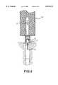
- FIG. 3is an enlarged sectional view of the adjustable pier
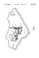
- FIG. 4is a perspective view of the adjustable pier showing it's disposition in a settled structure.
- the referenced number 20refers in general to the adjustable pier of the present invention with pier section 22 being driven into the ground by pier driver 10.
- pier driver 10drives pier section 22 into the ground and as shown in FIG. 2, a next pier section 22 is added having pier sleeve 24, which is essentially a length of pier having the same inside diameter as the pier section 22 outside diameter whereby said pier sleeve 24 is affixed to said pier section 22 by a normal means such as welding.
- Said pier sleeve 24merely allows another pier section 22 to be added to the previously driven pier section 22 and the next pier section 22 driven into the ground.
- pier section 22is 31/2" O.D. schedule 40 steel pipe. This process is continued with pier driver 10 driving pier section 22 into the ground until bedrock is reached.
- pier driver 10is a hydraulic hammer 12 and the driving of the pier section 22 is continued until the pier section 22 is not driven any further after 20 repetitions of the hydraulic hammer 12.
- pier section 2is cut off by ordinary means level with the ground. As shown in FIG. 2, a rebar 50 and high strength grout 52 is placed in the inside of pier 22. This keeps pier sections 22 and pier sleeve 24 from separating in the event ground movement occurs and maintains the integrity of pier system 20.
- Upper pier portion 26which is generally a schedule 40 pipe having an inside diameter similar to the pier sleeve 24 having a plug 30 which is a 3 to 4 inch section of the pier section 22 plug welded 31 near the upper end of upper pier portion 26 so that the upper most part of the upper pier portion 26 is level with the lower most portion of foundation 40 as shown in FIG. 3.
- Pier attachment 28which has an outside diameter slightly less than the inside diameter of the pier section 22 so that there is a snug fit between pier section 22 and pier attachment 28.
- Pier attachment 28has a foundation plate 27 affixed in approximately the middle of pier attachment 28 whereby the foundation plate 27 is a 1/4" flat steel plate having been cut to allow the foundation plate 27 to be slid on to the pier attachment 28 and then is affixed in a conventional means such as welding.
- pier attachment 28is placed into upper pier portion 26 until foundation plate 27 rests on the top of the upper pier portion 26, as shown in FIG. 3.
- Pier attachment 28has handle 29 welded on to its upper portion which provides assistance in carrying said pier attachment 28 and is adhered to by the concrete in the foundation 40 as shown in FIG. 3.
- a void material 41is placed under the foundation 40 between the adjustable piers to prevent the heaving of the soils from damaging the foundation 40.
- the upper pier portion 26has lateral supports 25 affixed by a standard means such as welding essentially opposing each other on said upper pier portion 26 and affixed in a manner that said lateral support 25 are in the earth 42.
- pier support 21is received by lateral support 25 and held in place by bolt 33.
- a hydraulic jack 50is placed between jack support 21 and foundation plate 27 and the foundation 40 is then leveled by using hydraulic jack 50.
- a pier sectionis cut to length and cut in half as a shim (not shown) and then welded together around the pier attachment and the foundation plate 28 then rests on the welded shim placing all of the weight of the lifed foundation once again on pier 22, maintaining the adjustment just made in place.
Landscapes
- Engineering & Computer Science (AREA)
- Structural Engineering (AREA)
- Life Sciences & Earth Sciences (AREA)
- General Life Sciences & Earth Sciences (AREA)
- Mining & Mineral Resources (AREA)
- Paleontology (AREA)
- Civil Engineering (AREA)
- General Engineering & Computer Science (AREA)
- Bridges Or Land Bridges (AREA)
Abstract
Description
This invention relates to an adjustable foundation piering system and more particularly to such a system which is an improvement over the foundation supports for building and the like.
In building construction on expansive soils such as bentonite, foundations are generally built on concrete piers which according to the engineering specifications should eliminate building foundation movement over time. However this is a fallacy and the foundations are required to be re-leveled as ground movement occurs. These soils cause substantial damage to home and buildings and require expensive re-work to them. In an effort to eliminate this movement of the soil many different actions are taken. Such actions include engineered concrete piers reinforced with steel rebar which are drilled to substantial depth and in some cases to depths of up to twenty feet. Once the pier is drilled and the reinforcing rebar is added, concrete is poured into the void and must set for at least seven (7) days before additional work can be performed after the seven (7) days, the foundation can be poured with attachments to the piers. After the building is complete, non-expansive soils are placed around the foundation which has necessitated the removal of the expansive soils from the area around the foundation to reduce the amount of heaving as much as possible. When the expansive soils are encountered the entire foundation rests on the piers with void material between the ground and the base of the foundation in between each pier.
Unfortunately, all of the processes used only reduce the problem encountered with expansive soils and in time the foundation shifts as a result of the expansive soil. Where caissons with rebar have been used, the soil must be removed and the rebar must be cut that is embedded into the foundation so that the foundation can be re-leveled, and in most cases requiring a portion of the foundation to be raised. There are numerous devices utilized to re-level the foundation including piering devices. The problem is that these devices require a substantial amount of work and monies. There is a piling system of Gregory, U.S. Pat. No. 4,754,588 which attempts to eliminate the problem with soils having various compaction. This system is extremely intricate and ties the pier to the foundation with an extensive amount of steel bars extending through the sleeve. The disadvantage of this system is again obvious as when there is movement of the foundation due to expansive soils, the piling system of Gregory will require the extensive shoring of the foundation that has been a problem with the concrete piers as well.
Nally, U.S. Pat. No. 5,123,209 shows a method of re-leveling a foundation after movement has occurred.
Gregory, U.S. Pat. No. 4,695,203, shows a method of shoring building's relating to the problems set forth earlier.
In Langenbach, Jr., U.S. Pat. No. 3,902,326, it is disclosed the use of a piling member which is capable of being driven into bedrock sufficient to shore a foundation. It utilized a hydraulic pump and attachment to the foundation as a means of shoring up the foundation as shown similarly in Ortez, Freeman, III, Rippe, and McCown, U.S. Pat. Nos., 5,492,437, 5,433,556, 5,234,287, and 5,154,539, respectively. Although, there are many methods of attempting to shore up a foundation including those discussed above, none provide a stabilization system that allows for correction after the devices have been installed.
It is therefore an object of the present invention to provide an adjustable foundation piering system in which piers are used which will support a foundation system in expansive soils such as Bentonite and the like. It is a further object of the present invention to provide a system that will allow adjustments to be made after the system is installed with minimal disruption to the surrounding soils.
It is still a further object of this invention to eliminate the need for drilling a hole in the ground to receive concrete and rebar to support a foundation. It is a further object of this invention to provide a system of the above type in which the piers are formed of steel pipes. It is a further object of this invention to provide a system of the above type in which the piers are driven into bedrock for supporting the foundation.
It is still a further object of the present invention to provide a system of the above type in which a plate extends horizontally from an insert whereby the foundation rests on said plate and provides a surface in which the foundation may be risen thereby.
It is a further object of the present invention to provide a system of the above type in which a sleeve with a smaller section plug welded inside rests on the pier and having two vertical plates affixed opposed to each other for attachment of a step for providing a lower support to raise the foundation when required. Since this is a pier system from the onset, if there are movements of the earth that require adjustments to be made such as releveling the foundation, the cost of repair is substantially less than any of the other systems as a new pier is not required and only minimal excavation is required to get to the lateral supports and once the foundation is leveled, a shim cut from a pier of the same size as the initial pier is placed in the area that is raised. This results in an overall system that is far less expensive than any of the casson systems or repair pier systems. This system is equivalent to having both systems in a single system.
The above brief description as well as further objects, features, and advantages of the present invention will be more fully appreciated by reference to the following detailed description of the presently preferred but non the less illustrative embodiments in accordance with the present invention when taken in conjunction with the accompanying drawings wherein:
FIG. 1 is a perspective view of the adjustable pier showing its disposition in a new foundation;
FIG. 2 is an exploded view of the adjustable pier for supporting building foundations in expandable soils showing its composite parts;
FIG. 3 is an enlarged sectional view of the adjustable pier;
FIG. 4 is a perspective view of the adjustable pier showing it's disposition in a settled structure.
Referring to FIG. 1 of the drawings, the referencednumber 20 refers in general to the adjustable pier of the present invention withpier section 22 being driven into the ground bypier driver 10. Inoperation pier driver 10 as shown in FIG. 1, drivespier section 22 into the ground and as shown in FIG. 2, anext pier section 22 is added havingpier sleeve 24, which is essentially a length of pier having the same inside diameter as thepier section 22 outside diameter whereby saidpier sleeve 24 is affixed to saidpier section 22 by a normal means such as welding. Saidpier sleeve 24 merely allows anotherpier section 22 to be added to the previously drivenpier section 22 and thenext pier section 22 driven into the ground. Typically,pier section 22 is 31/2" O.D.schedule 40 steel pipe. This process is continued withpier driver 10driving pier section 22 into the ground until bedrock is reached. Typicallypier driver 10 is ahydraulic hammer 12 and the driving of thepier section 22 is continued until thepier section 22 is not driven any further after 20 repetitions of thehydraulic hammer 12.
Once thehydraulic hammer 12 no longer will drivepier section 22 any further into the ground with the prescribed repetitions, then pier section 2 is cut off by ordinary means level with the ground. As shown in FIG. 2, arebar 50 andhigh strength grout 52 is placed in the inside ofpier 22. This keepspier sections 22 andpier sleeve 24 from separating in the event ground movement occurs and maintains the integrity ofpier system 20.Upper pier portion 26 which is generally aschedule 40 pipe having an inside diameter similar to thepier sleeve 24 having aplug 30 which is a 3 to 4 inch section of thepier section 22 plug welded 31 near the upper end ofupper pier portion 26 so that the upper most part of theupper pier portion 26 is level with the lower most portion offoundation 40 as shown in FIG. 3.
Whenfoundation 40 is built on a highly expansive soil, avoid material 41 is placed under thefoundation 40 between the adjustable piers to prevent the heaving of the soils from damaging thefoundation 40.
Additionally, theupper pier portion 26 haslateral supports 25 affixed by a standard means such as welding essentially opposing each other on saidupper pier portion 26 and affixed in a manner that saidlateral support 25 are in theearth 42.
Even the best pier system such as setforth hereinabove may eventually settle or heave. In the event such occurs,jack support 21 is received bylateral support 25 and held in place by bolt 33. Ahydraulic jack 50 is placed betweenjack support 21 andfoundation plate 27 and thefoundation 40 is then leveled by usinghydraulic jack 50. When thefoundation 40 is again level, a pier section is cut to length and cut in half as a shim (not shown) and then welded together around the pier attachment and thefoundation plate 28 then rests on the welded shim placing all of the weight of the lifed foundation once again onpier 22, maintaining the adjustment just made in place.
It is understood that the foregoing description and specific embodiments are merely illustrative of the best mode of the invention and the principle thereof, and various modifications and additions may be made to the apparatus and method by those skilled in the art, without departing from the spirit and scope of this invention, which is therefore understood to be limited only by the scope of the appended claims.
Claims (6)
1. An adjustable pier system for supporting a building foundation comprising:
a plurality of pier section members wherein said pier section members are connected together at the upper end of a first of said pier section members and a lower end of a second of said pier section members by a pier sleeve means having an inside diameter larger than the outside diameter of said plurality of pier section members and is permanently affixed to either said upper end of said first pier sections member or to said lower end of said second pier sections member allowing said plurality of pier section members to be driven into the ground;
an upper pier portion member having an inside diameter slightly greater than the outside diameter of said plurality of pier section members wherein said upper pier portion member has permanently affixed within its upper portion a small portion of one of said pier section members whereby said upper pier portion member rests on said one of said pier section members;
said upper pier portion member having a pair of lateral support elements permanently affixed near the middle of the upper half of said upper pier portion member wherein said lateral support elements are parallel to each other on opposite sides of said upper pier portion member; each of said lateral support elements having an opening for adhering a lifting support means;
said lifting support means having a horizontal plate means for supporting a lifting means and a vertical member means having an opening coinciding with said opening on said lateral support means for temporarily affixing said lifting support means to said lateral support means when adjustment of said foundation is required;
a pier attaching means having its outside diameter smaller than said pier section members inside diameter so that said pier attaching means slides within said upper pier portion member and said pier section members;
said pier attaching means having a gripping means permanently affixed at the upper portion of said pier attaching means for carrying said upper portion of said pier attaching means and for adherence within said building foundation;
said pier attaching means further having a foundation plate member permanently affixed horizontally to and centered within said pier attaching means whereby said foundation plate means rests on said upper pier portion member completing said adjustable pier system.
2. The adjustable pier system of claim 1 wherein said plurality of pier section members are sections of schedule 40 pipe.
3. The adjustable pier system of claim 1 wherein said pier sleeve means is a section of schedule 40 pipe having its inside diameter approximately the same size as the outside diameter of said pier section members.
4. The adjustable pier system of claim 1, wherein said upper pier portion member is a larger section of schedule 40 pipe than said pier sleeve means.
5. The adjustable pier system of claim 1 further comprising a shim affixed to said pier attaching means.
6. An adjustable pier system for supporting a building foundation comprising:
a plurality of pier sections wherein said pier sections are connected together at the upper end of a first said pier section and a lower end of a second said pier section by a pier sleeve having an inside diameter larger than the outside diameter of said pier sections and is permanently affixed to either said upper end of said first pier section or to said lower end of said second pier section allowing said plurality of pier sections to be driven into the ground;
an upper pier portion having an inside diameter slightly greater than the outside diameter of said pier sections wherein said upper pier portion has permanently affixed within its upper portion a small portion of one of said pier sections whereby said upper pier portion rests on said pier section;
said upper pier portion having a pair of lateral supports permanently affixed near the middle of the upper half of said upper pier portion wherein said lateral supports are parallel to each other on opposite sides of said upper pier portion; each of said lateral supports having an opening for adhering a jack support;
said jack support having a horizontal plate for supporting a jack and a vertical member having an opening coinciding with said opening on said lateral supports for temporarily affixing said jack support to said lateral supports when adjustment of said foundation is required;
a pier attachment having its outside diameter smaller than said pier sections inside diameter so that said pier attachment slides within said upper pier portion and said pier sections;
said pier attachment having a handle permanently affixed at the upper portion of said pier attachment for carrying said upper portion and for adherence within said building foundation;
said pier attachment further having a foundation plate permanently affixed horizontally to and centered about said pier attachment whereby said foundation plate is the base of said foundation.
Priority Applications (1)
| Application Number | Priority Date | Filing Date | Title |
|---|---|---|---|
| US09/107,166US6074133A (en) | 1998-06-10 | 1998-06-10 | Adjustable foundation piering system |
Applications Claiming Priority (1)
| Application Number | Priority Date | Filing Date | Title |
|---|---|---|---|
| US09/107,166US6074133A (en) | 1998-06-10 | 1998-06-10 | Adjustable foundation piering system |
Publications (1)
| Publication Number | Publication Date |
|---|---|
| US6074133Atrue US6074133A (en) | 2000-06-13 |
Family
ID=22315181
Family Applications (1)
| Application Number | Title | Priority Date | Filing Date |
|---|---|---|---|
| US09/107,166Expired - Fee RelatedUS6074133A (en) | 1998-06-10 | 1998-06-10 | Adjustable foundation piering system |
Country Status (1)
| Country | Link |
|---|---|
| US (1) | US6074133A (en) |
Cited By (79)
| Publication number | Priority date | Publication date | Assignee | Title |
|---|---|---|---|---|
| US20010047866A1 (en)* | 1998-12-07 | 2001-12-06 | Cook Robert Lance | Wellbore casing |
| US6447209B1 (en)* | 1999-06-21 | 2002-09-10 | Richard D. Ruiz, Llc | Apparatus for mounting power cylinders for driving piers |
| US6557640B1 (en) | 1998-12-07 | 2003-05-06 | Shell Oil Company | Lubrication and self-cleaning system for expansion mandrel |
| US6568471B1 (en) | 1999-02-26 | 2003-05-27 | Shell Oil Company | Liner hanger |
| US6575240B1 (en)* | 1998-12-07 | 2003-06-10 | Shell Oil Company | System and method for driving pipe |
| US6575250B1 (en) | 1999-11-15 | 2003-06-10 | Shell Oil Company | Expanding a tubular element in a wellbore |
| US6634431B2 (en) | 1998-11-16 | 2003-10-21 | Robert Lance Cook | Isolation of subterranean zones |
| US6640903B1 (en) | 1998-12-07 | 2003-11-04 | Shell Oil Company | Forming a wellbore casing while simultaneously drilling a wellbore |
| US20030208974A1 (en)* | 2002-02-25 | 2003-11-13 | James Creed | Mechanical device for flaring a piling member |
| US6712154B2 (en) | 1998-11-16 | 2004-03-30 | Enventure Global Technology | Isolation of subterranean zones |
| US20040071511A1 (en)* | 2002-07-22 | 2004-04-15 | Donald May | Apparatus and method of supporting a structure with a pier |
| US6725919B2 (en) | 1998-12-07 | 2004-04-27 | Shell Oil Company | Forming a wellbore casing while simultaneously drilling a wellbore |
| US6745845B2 (en) | 1998-11-16 | 2004-06-08 | Shell Oil Company | Isolation of subterranean zones |
| US6823937B1 (en) | 1998-12-07 | 2004-11-30 | Shell Oil Company | Wellhead |
| US6892819B2 (en) | 1998-12-07 | 2005-05-17 | Shell Oil Company | Forming a wellbore casing while simultaneously drilling a wellbore |
| US20050252104A1 (en)* | 2004-03-30 | 2005-11-17 | Tri-Dyne Llc | Adjustable pier |
| US6968618B2 (en) | 1999-04-26 | 2005-11-29 | Shell Oil Company | Expandable connector |
| US6976541B2 (en) | 2000-09-18 | 2005-12-20 | Shell Oil Company | Liner hanger with sliding sleeve valve |
| US7011161B2 (en) | 1998-12-07 | 2006-03-14 | Shell Oil Company | Structural support |
| US20060067794A1 (en)* | 2004-09-24 | 2006-03-30 | Leroy Mitchell | Method and apparatus for raising, leveling, and supporting displaced foundation allowing for readjustment after installation |
| US7048067B1 (en) | 1999-11-01 | 2006-05-23 | Shell Oil Company | Wellbore casing repair |
| US7055608B2 (en) | 1999-03-11 | 2006-06-06 | Shell Oil Company | Forming a wellbore casing while simultaneously drilling a wellbore |
| US7100685B2 (en) | 2000-10-02 | 2006-09-05 | Enventure Global Technology | Mono-diameter wellbore casing |
| US7100684B2 (en) | 2000-07-28 | 2006-09-05 | Enventure Global Technology | Liner hanger with standoffs |
| US7121352B2 (en) | 1998-11-16 | 2006-10-17 | Enventure Global Technology | Isolation of subterranean zones |
| US20060269364A1 (en)* | 2005-05-24 | 2006-11-30 | Donald May | Structural pier and method for installing the same |
| US7168499B2 (en) | 1998-11-16 | 2007-01-30 | Shell Oil Company | Radial expansion of tubular members |
| US7168496B2 (en) | 2001-07-06 | 2007-01-30 | Eventure Global Technology | Liner hanger |
| US7172024B2 (en) | 2000-10-02 | 2007-02-06 | Shell Oil Company | Mono-diameter wellbore casing |
| US7195064B2 (en) | 1998-12-07 | 2007-03-27 | Enventure Global Technology | Mono-diameter wellbore casing |
| US7220081B1 (en)* | 2006-04-18 | 2007-05-22 | Gantt Jr William Allen | Concentric load bearing piping with liner for foundation anchor |
| US7231985B2 (en) | 1998-11-16 | 2007-06-19 | Shell Oil Company | Radial expansion of tubular members |
| US7234531B2 (en) | 1999-12-03 | 2007-06-26 | Enventure Global Technology, Llc | Mono-diameter wellbore casing |
| US7258168B2 (en) | 2001-07-27 | 2007-08-21 | Enventure Global Technology L.L.C. | Liner hanger with slip joint sealing members and method of use |
| US7290605B2 (en) | 2001-12-27 | 2007-11-06 | Enventure Global Technology | Seal receptacle using expandable liner hanger |
| US7290616B2 (en) | 2001-07-06 | 2007-11-06 | Enventure Global Technology, L.L.C. | Liner hanger |
| US7308755B2 (en) | 2003-06-13 | 2007-12-18 | Shell Oil Company | Apparatus for forming a mono-diameter wellbore casing |
| US7325602B2 (en) | 2000-10-02 | 2008-02-05 | Shell Oil Company | Method and apparatus for forming a mono-diameter wellbore casing |
| US7350563B2 (en) | 1999-07-09 | 2008-04-01 | Enventure Global Technology, L.L.C. | System for lining a wellbore casing |
| US7350564B2 (en) | 1998-12-07 | 2008-04-01 | Enventure Global Technology, L.L.C. | Mono-diameter wellbore casing |
| US7360591B2 (en) | 2002-05-29 | 2008-04-22 | Enventure Global Technology, Llc | System for radially expanding a tubular member |
| US7363984B2 (en) | 1998-12-07 | 2008-04-29 | Enventure Global Technology, Llc | System for radially expanding a tubular member |
| US7377326B2 (en) | 2002-08-23 | 2008-05-27 | Enventure Global Technology, L.L.C. | Magnetic impulse applied sleeve method of forming a wellbore casing |
| US7383889B2 (en) | 2001-11-12 | 2008-06-10 | Enventure Global Technology, Llc | Mono diameter wellbore casing |
| US7398832B2 (en) | 2002-06-10 | 2008-07-15 | Enventure Global Technology, Llc | Mono-diameter wellbore casing |
| US7404444B2 (en) | 2002-09-20 | 2008-07-29 | Enventure Global Technology | Protective sleeve for expandable tubulars |
| US7410000B2 (en) | 2001-01-17 | 2008-08-12 | Enventure Global Technology, Llc. | Mono-diameter wellbore casing |
| US7416027B2 (en) | 2001-09-07 | 2008-08-26 | Enventure Global Technology, Llc | Adjustable expansion cone assembly |
| US7424918B2 (en) | 2002-08-23 | 2008-09-16 | Enventure Global Technology, L.L.C. | Interposed joint sealing layer method of forming a wellbore casing |
| US7438133B2 (en) | 2003-02-26 | 2008-10-21 | Enventure Global Technology, Llc | Apparatus and method for radially expanding and plastically deforming a tubular member |
| US7503393B2 (en) | 2003-01-27 | 2009-03-17 | Enventure Global Technology, Inc. | Lubrication system for radially expanding tubular members |
| US7513313B2 (en) | 2002-09-20 | 2009-04-07 | Enventure Global Technology, Llc | Bottom plug for forming a mono diameter wellbore casing |
| US7516790B2 (en) | 1999-12-03 | 2009-04-14 | Enventure Global Technology, Llc | Mono-diameter wellbore casing |
| US7552776B2 (en) | 1998-12-07 | 2009-06-30 | Enventure Global Technology, Llc | Anchor hangers |
| US7571774B2 (en) | 2002-09-20 | 2009-08-11 | Eventure Global Technology | Self-lubricating expansion mandrel for expandable tubular |
| US20090211178A1 (en)* | 2008-02-27 | 2009-08-27 | Marshall Frederick S | System for Forming a Movable Slab Foundation |
| US7603758B2 (en) | 1998-12-07 | 2009-10-20 | Shell Oil Company | Method of coupling a tubular member |
| USD612954S1 (en) | 2008-10-27 | 2010-03-30 | Magnum Piering, Inc. | Helical pier |
| US7712522B2 (en) | 2003-09-05 | 2010-05-11 | Enventure Global Technology, Llc | Expansion cone and system |
| US7740076B2 (en) | 2002-04-12 | 2010-06-22 | Enventure Global Technology, L.L.C. | Protective sleeve for threaded connections for expandable liner hanger |
| US7739917B2 (en) | 2002-09-20 | 2010-06-22 | Enventure Global Technology, Llc | Pipe formability evaluation for expandable tubulars |
| US7775290B2 (en) | 2003-04-17 | 2010-08-17 | Enventure Global Technology, Llc | Apparatus for radially expanding and plastically deforming a tubular member |
| US7793721B2 (en) | 2003-03-11 | 2010-09-14 | Eventure Global Technology, Llc | Apparatus for radially expanding and plastically deforming a tubular member |
| US7819185B2 (en) | 2004-08-13 | 2010-10-26 | Enventure Global Technology, Llc | Expandable tubular |
| US7886831B2 (en) | 2003-01-22 | 2011-02-15 | Enventure Global Technology, L.L.C. | Apparatus for radially expanding and plastically deforming a tubular member |
| US7914235B1 (en)* | 2006-05-16 | 2011-03-29 | Arizona Ramjack, Llc | Methods and apparatus for foundation system |
| US7918284B2 (en) | 2002-04-15 | 2011-04-05 | Enventure Global Technology, L.L.C. | Protective sleeve for threaded connections for expandable liner hanger |
| US20120114425A1 (en)* | 2010-11-09 | 2012-05-10 | Hubbell Incorporated | Transition coupling between cylindrical drive shaft and helical pile shaft |
| US20150218771A1 (en)* | 2014-01-31 | 2015-08-06 | J. Stephen West | Foundation pier system |
| US9631335B2 (en)* | 2013-08-22 | 2017-04-25 | Goliathtech Inc. | Pile, pile head and connector therefor |
| US20180135269A1 (en)* | 2016-11-16 | 2018-05-17 | Goliathtech Inc. | Support assembly for a building structure |
| US20180148901A1 (en)* | 2016-11-29 | 2018-05-31 | Hubbell Incorporated | Supports for Helical Piles and Anchors |
| CN108166488A (en)* | 2017-12-27 | 2018-06-15 | 温州中海建设有限公司 | A kind of built pile of ground foundation engineering and preparation method thereof |
| US10138641B2 (en)* | 2013-11-26 | 2018-11-27 | Arman Innovations S.A. | Method for restoring a structure having a crack by following a curve representing the separation of the edges of the crack |
| US10428516B2 (en)* | 2017-09-08 | 2019-10-01 | Patents of Tomball, LLC | Method and apparatus for repairing a tilt wall construction |
| WO2019236721A1 (en)* | 2018-06-05 | 2019-12-12 | Hodge Malcolm H | Foundation repair method |
| US11299863B2 (en)* | 2016-11-16 | 2022-04-12 | Goliathtech, Inc. | Support assembly for a building structure |
| US11346099B2 (en)* | 2018-12-31 | 2022-05-31 | Independence Materials Group, Llc | Apparatus and method for lifting a concrete slab |
| US12139871B1 (en)* | 2018-09-11 | 2024-11-12 | Glenn P. Gillen | Precast deep foundation system |
Citations (16)
| Publication number | Priority date | Publication date | Assignee | Title |
|---|---|---|---|---|
| US3902326A (en)* | 1974-05-16 | 1975-09-02 | Jr George F Langenbach | Apparatus for and method of shoring a foundation |
| US4070867A (en)* | 1974-12-13 | 1978-01-31 | Cassidy Paul G | Negative friction pile and isolating casing |
| US4695203A (en)* | 1985-04-11 | 1987-09-22 | Gregory Enterprises, Inc. | Method and apparatus for shoring and supporting a building foundation |
| US4765777A (en)* | 1987-06-29 | 1988-08-23 | Gregory Steven D | Apparatus and method for raising and supporting a building |
| US5011336A (en)* | 1990-01-16 | 1991-04-30 | A. B. Chance Company | Underpinning anchor system |
| US5123209A (en)* | 1990-12-07 | 1992-06-23 | Nally W T | Earth engineering apparatus and method |
| US5135335A (en)* | 1990-03-12 | 1992-08-04 | Stephens Jerry B | Hydraulic jacking apparatus |
| US5154539A (en)* | 1991-09-18 | 1992-10-13 | Mccown Sr William B | Foundation lifting and stabilizing apparatus |
| US5176472A (en)* | 1983-02-08 | 1993-01-05 | Kinder William D | Foundation shoring method and means |
| US5205673A (en)* | 1991-07-18 | 1993-04-27 | Power Lift Foundation Repair | Foundation slab support and lifting apparatus |
| US5213448A (en)* | 1992-12-11 | 1993-05-25 | A. B. Chance Company | Underpinning bracket for uplift and settlement loading |
| US5234287A (en)* | 1989-07-27 | 1993-08-10 | Rippe Jr Dondeville M | Apparatus and process for stabilizing foundations |
| US5433556A (en)* | 1991-06-11 | 1995-07-18 | Freeman Piering Systems, Inc. | System for underpinning a building |
| US5492437A (en)* | 1995-05-09 | 1996-02-20 | Ortiz; Leo P. | Self-aligning devices and methods for lifting and securing structures |
| US5722798A (en)* | 1996-02-16 | 1998-03-03 | Gregory Enterprises | System for raising and supporting a building |
| US5800094A (en)* | 1997-02-05 | 1998-09-01 | Jones; Robert L. | Apparatus for lifting and supporting structures |
- 1998
- 1998-06-10USUS09/107,166patent/US6074133A/ennot_activeExpired - Fee Related
Patent Citations (16)
| Publication number | Priority date | Publication date | Assignee | Title |
|---|---|---|---|---|
| US3902326A (en)* | 1974-05-16 | 1975-09-02 | Jr George F Langenbach | Apparatus for and method of shoring a foundation |
| US4070867A (en)* | 1974-12-13 | 1978-01-31 | Cassidy Paul G | Negative friction pile and isolating casing |
| US5176472A (en)* | 1983-02-08 | 1993-01-05 | Kinder William D | Foundation shoring method and means |
| US4695203A (en)* | 1985-04-11 | 1987-09-22 | Gregory Enterprises, Inc. | Method and apparatus for shoring and supporting a building foundation |
| US4765777A (en)* | 1987-06-29 | 1988-08-23 | Gregory Steven D | Apparatus and method for raising and supporting a building |
| US5234287A (en)* | 1989-07-27 | 1993-08-10 | Rippe Jr Dondeville M | Apparatus and process for stabilizing foundations |
| US5011336A (en)* | 1990-01-16 | 1991-04-30 | A. B. Chance Company | Underpinning anchor system |
| US5135335A (en)* | 1990-03-12 | 1992-08-04 | Stephens Jerry B | Hydraulic jacking apparatus |
| US5123209A (en)* | 1990-12-07 | 1992-06-23 | Nally W T | Earth engineering apparatus and method |
| US5433556A (en)* | 1991-06-11 | 1995-07-18 | Freeman Piering Systems, Inc. | System for underpinning a building |
| US5205673A (en)* | 1991-07-18 | 1993-04-27 | Power Lift Foundation Repair | Foundation slab support and lifting apparatus |
| US5154539A (en)* | 1991-09-18 | 1992-10-13 | Mccown Sr William B | Foundation lifting and stabilizing apparatus |
| US5213448A (en)* | 1992-12-11 | 1993-05-25 | A. B. Chance Company | Underpinning bracket for uplift and settlement loading |
| US5492437A (en)* | 1995-05-09 | 1996-02-20 | Ortiz; Leo P. | Self-aligning devices and methods for lifting and securing structures |
| US5722798A (en)* | 1996-02-16 | 1998-03-03 | Gregory Enterprises | System for raising and supporting a building |
| US5800094A (en)* | 1997-02-05 | 1998-09-01 | Jones; Robert L. | Apparatus for lifting and supporting structures |
Cited By (144)
| Publication number | Priority date | Publication date | Assignee | Title |
|---|---|---|---|---|
| US6634431B2 (en) | 1998-11-16 | 2003-10-21 | Robert Lance Cook | Isolation of subterranean zones |
| US7357190B2 (en) | 1998-11-16 | 2008-04-15 | Shell Oil Company | Radial expansion of tubular members |
| US7299881B2 (en) | 1998-11-16 | 2007-11-27 | Shell Oil Company | Radial expansion of tubular members |
| US7275601B2 (en) | 1998-11-16 | 2007-10-02 | Shell Oil Company | Radial expansion of tubular members |
| US7270188B2 (en) | 1998-11-16 | 2007-09-18 | Shell Oil Company | Radial expansion of tubular members |
| US7246667B2 (en) | 1998-11-16 | 2007-07-24 | Shell Oil Company | Radial expansion of tubular members |
| US7231985B2 (en) | 1998-11-16 | 2007-06-19 | Shell Oil Company | Radial expansion of tubular members |
| US7168499B2 (en) | 1998-11-16 | 2007-01-30 | Shell Oil Company | Radial expansion of tubular members |
| US7121352B2 (en) | 1998-11-16 | 2006-10-17 | Enventure Global Technology | Isolation of subterranean zones |
| US7108072B2 (en) | 1998-11-16 | 2006-09-19 | Shell Oil Company | Lubrication and self-cleaning system for expansion mandrel |
| US6745845B2 (en) | 1998-11-16 | 2004-06-08 | Shell Oil Company | Isolation of subterranean zones |
| US6712154B2 (en) | 1998-11-16 | 2004-03-30 | Enventure Global Technology | Isolation of subterranean zones |
| US7240728B2 (en) | 1998-12-07 | 2007-07-10 | Shell Oil Company | Expandable tubulars with a radial passage and wall portions with different wall thicknesses |
| US7159665B2 (en) | 1998-12-07 | 2007-01-09 | Shell Oil Company | Wellbore casing |
| US7665532B2 (en) | 1998-12-07 | 2010-02-23 | Shell Oil Company | Pipeline |
| US7216701B2 (en) | 1998-12-07 | 2007-05-15 | Shell Oil Company | Apparatus for expanding a tubular member |
| US20010047866A1 (en)* | 1998-12-07 | 2001-12-06 | Cook Robert Lance | Wellbore casing |
| US6631760B2 (en) | 1998-12-07 | 2003-10-14 | Shell Oil Company | Tie back liner for a well system |
| US7603758B2 (en) | 1998-12-07 | 2009-10-20 | Shell Oil Company | Method of coupling a tubular member |
| US6725919B2 (en) | 1998-12-07 | 2004-04-27 | Shell Oil Company | Forming a wellbore casing while simultaneously drilling a wellbore |
| US6739392B2 (en) | 1998-12-07 | 2004-05-25 | Shell Oil Company | Forming a wellbore casing while simultaneously drilling a wellbore |
| US7240729B2 (en) | 1998-12-07 | 2007-07-10 | Shell Oil Company | Apparatus for expanding a tubular member |
| US6758278B2 (en) | 1998-12-07 | 2004-07-06 | Shell Oil Company | Forming a wellbore casing while simultaneously drilling a wellbore |
| US6823937B1 (en) | 1998-12-07 | 2004-11-30 | Shell Oil Company | Wellhead |
| US7198100B2 (en) | 1998-12-07 | 2007-04-03 | Shell Oil Company | Apparatus for expanding a tubular member |
| US7195064B2 (en) | 1998-12-07 | 2007-03-27 | Enventure Global Technology | Mono-diameter wellbore casing |
| US6892819B2 (en) | 1998-12-07 | 2005-05-17 | Shell Oil Company | Forming a wellbore casing while simultaneously drilling a wellbore |
| US7552776B2 (en) | 1998-12-07 | 2009-06-30 | Enventure Global Technology, Llc | Anchor hangers |
| US7195061B2 (en) | 1998-12-07 | 2007-03-27 | Shell Oil Company | Apparatus for expanding a tubular member |
| US6561227B2 (en) | 1998-12-07 | 2003-05-13 | Shell Oil Company | Wellbore casing |
| US7357188B1 (en) | 1998-12-07 | 2008-04-15 | Shell Oil Company | Mono-diameter wellbore casing |
| US7174964B2 (en) | 1998-12-07 | 2007-02-13 | Shell Oil Company | Wellhead with radially expanded tubulars |
| US7011161B2 (en) | 1998-12-07 | 2006-03-14 | Shell Oil Company | Structural support |
| US6640903B1 (en) | 1998-12-07 | 2003-11-04 | Shell Oil Company | Forming a wellbore casing while simultaneously drilling a wellbore |
| US7021390B2 (en) | 1998-12-07 | 2006-04-04 | Shell Oil Company | Tubular liner for wellbore casing |
| US7036582B2 (en) | 1998-12-07 | 2006-05-02 | Shell Oil Company | Expansion cone for radially expanding tubular members |
| US6497289B1 (en) | 1998-12-07 | 2002-12-24 | Robert Lance Cook | Method of creating a casing in a borehole |
| US7044218B2 (en) | 1998-12-07 | 2006-05-16 | Shell Oil Company | Apparatus for radially expanding tubular members |
| US6557640B1 (en) | 1998-12-07 | 2003-05-06 | Shell Oil Company | Lubrication and self-cleaning system for expansion mandrel |
| US6470966B2 (en) | 1998-12-07 | 2002-10-29 | Robert Lance Cook | Apparatus for forming wellbore casing |
| US7048062B2 (en) | 1998-12-07 | 2006-05-23 | Shell Oil Company | Method of selecting tubular members |
| US6575240B1 (en)* | 1998-12-07 | 2003-06-10 | Shell Oil Company | System and method for driving pipe |
| US7147053B2 (en) | 1998-12-07 | 2006-12-12 | Shell Oil Company | Wellhead |
| US7077213B2 (en) | 1998-12-07 | 2006-07-18 | Shell Oil Company | Expansion cone for radially expanding tubular members |
| US7077211B2 (en) | 1998-12-07 | 2006-07-18 | Shell Oil Company | Method of creating a casing in a borehole |
| US7434618B2 (en) | 1998-12-07 | 2008-10-14 | Shell Oil Company | Apparatus for expanding a tubular member |
| US7350564B2 (en) | 1998-12-07 | 2008-04-01 | Enventure Global Technology, L.L.C. | Mono-diameter wellbore casing |
| US7363984B2 (en) | 1998-12-07 | 2008-04-29 | Enventure Global Technology, Llc | System for radially expanding a tubular member |
| US7419009B2 (en) | 1998-12-07 | 2008-09-02 | Shell Oil Company | Apparatus for radially expanding and plastically deforming a tubular member |
| US7108061B2 (en) | 1998-12-07 | 2006-09-19 | Shell Oil Company | Expander for a tapered liner with a shoe |
| US7121337B2 (en) | 1998-12-07 | 2006-10-17 | Shell Oil Company | Apparatus for expanding a tubular member |
| US7159667B2 (en) | 1999-02-25 | 2007-01-09 | Shell Oil Company | Method of coupling a tubular member to a preexisting structure |
| US7044221B2 (en) | 1999-02-26 | 2006-05-16 | Shell Oil Company | Apparatus for coupling a tubular member to a preexisting structure |
| US6966370B2 (en) | 1999-02-26 | 2005-11-22 | Shell Oil Company | Apparatus for actuating an annular piston |
| US7063142B2 (en) | 1999-02-26 | 2006-06-20 | Shell Oil Company | Method of applying an axial force to an expansion cone |
| US6568471B1 (en) | 1999-02-26 | 2003-05-27 | Shell Oil Company | Liner hanger |
| US6631759B2 (en) | 1999-02-26 | 2003-10-14 | Shell Oil Company | Apparatus for radially expanding a tubular member |
| US7040396B2 (en) | 1999-02-26 | 2006-05-09 | Shell Oil Company | Apparatus for releasably coupling two elements |
| US6684947B2 (en) | 1999-02-26 | 2004-02-03 | Shell Oil Company | Apparatus for radially expanding a tubular member |
| US6705395B2 (en) | 1999-02-26 | 2004-03-16 | Shell Oil Company | Wellbore casing |
| US6631769B2 (en) | 1999-02-26 | 2003-10-14 | Shell Oil Company | Method of operating an apparatus for radially expanding a tubular member |
| US6857473B2 (en) | 1999-02-26 | 2005-02-22 | Shell Oil Company | Method of coupling a tubular member to a preexisting structure |
| US7556092B2 (en) | 1999-02-26 | 2009-07-07 | Enventure Global Technology, Llc | Flow control system for an apparatus for radially expanding tubular members |
| US7055608B2 (en) | 1999-03-11 | 2006-06-06 | Shell Oil Company | Forming a wellbore casing while simultaneously drilling a wellbore |
| US7438132B2 (en) | 1999-03-11 | 2008-10-21 | Shell Oil Company | Concentric pipes expanded at the pipe ends and method of forming |
| US6968618B2 (en) | 1999-04-26 | 2005-11-29 | Shell Oil Company | Expandable connector |
| US6447209B1 (en)* | 1999-06-21 | 2002-09-10 | Richard D. Ruiz, Llc | Apparatus for mounting power cylinders for driving piers |
| US7350563B2 (en) | 1999-07-09 | 2008-04-01 | Enventure Global Technology, L.L.C. | System for lining a wellbore casing |
| US7048067B1 (en) | 1999-11-01 | 2006-05-23 | Shell Oil Company | Wellbore casing repair |
| US6575250B1 (en) | 1999-11-15 | 2003-06-10 | Shell Oil Company | Expanding a tubular element in a wellbore |
| US7516790B2 (en) | 1999-12-03 | 2009-04-14 | Enventure Global Technology, Llc | Mono-diameter wellbore casing |
| US7234531B2 (en) | 1999-12-03 | 2007-06-26 | Enventure Global Technology, Llc | Mono-diameter wellbore casing |
| US7100684B2 (en) | 2000-07-28 | 2006-09-05 | Enventure Global Technology | Liner hanger with standoffs |
| US7172021B2 (en) | 2000-09-18 | 2007-02-06 | Shell Oil Company | Liner hanger with sliding sleeve valve |
| US6976541B2 (en) | 2000-09-18 | 2005-12-20 | Shell Oil Company | Liner hanger with sliding sleeve valve |
| US7325602B2 (en) | 2000-10-02 | 2008-02-05 | Shell Oil Company | Method and apparatus for forming a mono-diameter wellbore casing |
| US7363690B2 (en) | 2000-10-02 | 2008-04-29 | Shell Oil Company | Method and apparatus for forming a mono-diameter wellbore casing |
| US7172024B2 (en) | 2000-10-02 | 2007-02-06 | Shell Oil Company | Mono-diameter wellbore casing |
| US7172019B2 (en) | 2000-10-02 | 2007-02-06 | Shell Oil Company | Method and apparatus for forming a mono-diameter wellbore casing |
| US7146702B2 (en) | 2000-10-02 | 2006-12-12 | Shell Oil Company | Method and apparatus for forming a mono-diameter wellbore casing |
| US7363691B2 (en) | 2000-10-02 | 2008-04-29 | Shell Oil Company | Method and apparatus for forming a mono-diameter wellbore casing |
| US7201223B2 (en) | 2000-10-02 | 2007-04-10 | Shell Oil Company | Method and apparatus for forming a mono-diameter wellbore casing |
| US7100685B2 (en) | 2000-10-02 | 2006-09-05 | Enventure Global Technology | Mono-diameter wellbore casing |
| US7204007B2 (en) | 2000-10-02 | 2007-04-17 | Shell Oil Company | Method and apparatus for forming a mono-diameter wellbore casing |
| US7410000B2 (en) | 2001-01-17 | 2008-08-12 | Enventure Global Technology, Llc. | Mono-diameter wellbore casing |
| US7290616B2 (en) | 2001-07-06 | 2007-11-06 | Enventure Global Technology, L.L.C. | Liner hanger |
| US7168496B2 (en) | 2001-07-06 | 2007-01-30 | Eventure Global Technology | Liner hanger |
| US7258168B2 (en) | 2001-07-27 | 2007-08-21 | Enventure Global Technology L.L.C. | Liner hanger with slip joint sealing members and method of use |
| US7416027B2 (en) | 2001-09-07 | 2008-08-26 | Enventure Global Technology, Llc | Adjustable expansion cone assembly |
| US7559365B2 (en) | 2001-11-12 | 2009-07-14 | Enventure Global Technology, Llc | Collapsible expansion cone |
| US7383889B2 (en) | 2001-11-12 | 2008-06-10 | Enventure Global Technology, Llc | Mono diameter wellbore casing |
| US7290605B2 (en) | 2001-12-27 | 2007-11-06 | Enventure Global Technology | Seal receptacle using expandable liner hanger |
| US20030208974A1 (en)* | 2002-02-25 | 2003-11-13 | James Creed | Mechanical device for flaring a piling member |
| US7004685B2 (en) | 2002-02-25 | 2006-02-28 | A-1 Concrete Leveling Inc. | Mechanical device for flaring a piling member |
| US7740076B2 (en) | 2002-04-12 | 2010-06-22 | Enventure Global Technology, L.L.C. | Protective sleeve for threaded connections for expandable liner hanger |
| US7918284B2 (en) | 2002-04-15 | 2011-04-05 | Enventure Global Technology, L.L.C. | Protective sleeve for threaded connections for expandable liner hanger |
| US7360591B2 (en) | 2002-05-29 | 2008-04-22 | Enventure Global Technology, Llc | System for radially expanding a tubular member |
| US7398832B2 (en) | 2002-06-10 | 2008-07-15 | Enventure Global Technology, Llc | Mono-diameter wellbore casing |
| US20040071511A1 (en)* | 2002-07-22 | 2004-04-15 | Donald May | Apparatus and method of supporting a structure with a pier |
| US6872031B2 (en)* | 2002-07-22 | 2005-03-29 | Donald May | Apparatus and method of supporting a structure with a pier |
| US7377326B2 (en) | 2002-08-23 | 2008-05-27 | Enventure Global Technology, L.L.C. | Magnetic impulse applied sleeve method of forming a wellbore casing |
| US7424918B2 (en) | 2002-08-23 | 2008-09-16 | Enventure Global Technology, L.L.C. | Interposed joint sealing layer method of forming a wellbore casing |
| US7571774B2 (en) | 2002-09-20 | 2009-08-11 | Eventure Global Technology | Self-lubricating expansion mandrel for expandable tubular |
| US7739917B2 (en) | 2002-09-20 | 2010-06-22 | Enventure Global Technology, Llc | Pipe formability evaluation for expandable tubulars |
| US7513313B2 (en) | 2002-09-20 | 2009-04-07 | Enventure Global Technology, Llc | Bottom plug for forming a mono diameter wellbore casing |
| US7404444B2 (en) | 2002-09-20 | 2008-07-29 | Enventure Global Technology | Protective sleeve for expandable tubulars |
| US7886831B2 (en) | 2003-01-22 | 2011-02-15 | Enventure Global Technology, L.L.C. | Apparatus for radially expanding and plastically deforming a tubular member |
| US7503393B2 (en) | 2003-01-27 | 2009-03-17 | Enventure Global Technology, Inc. | Lubrication system for radially expanding tubular members |
| US7438133B2 (en) | 2003-02-26 | 2008-10-21 | Enventure Global Technology, Llc | Apparatus and method for radially expanding and plastically deforming a tubular member |
| US7793721B2 (en) | 2003-03-11 | 2010-09-14 | Eventure Global Technology, Llc | Apparatus for radially expanding and plastically deforming a tubular member |
| US7775290B2 (en) | 2003-04-17 | 2010-08-17 | Enventure Global Technology, Llc | Apparatus for radially expanding and plastically deforming a tubular member |
| US7308755B2 (en) | 2003-06-13 | 2007-12-18 | Shell Oil Company | Apparatus for forming a mono-diameter wellbore casing |
| US7712522B2 (en) | 2003-09-05 | 2010-05-11 | Enventure Global Technology, Llc | Expansion cone and system |
| US7454871B2 (en) | 2004-03-30 | 2008-11-25 | Joseph Sproules | Adjustable pier |
| US20050252104A1 (en)* | 2004-03-30 | 2005-11-17 | Tri-Dyne Llc | Adjustable pier |
| US7819185B2 (en) | 2004-08-13 | 2010-10-26 | Enventure Global Technology, Llc | Expandable tubular |
| US20060067794A1 (en)* | 2004-09-24 | 2006-03-30 | Leroy Mitchell | Method and apparatus for raising, leveling, and supporting displaced foundation allowing for readjustment after installation |
| US7090435B2 (en) | 2004-09-24 | 2006-08-15 | Leroy Mitchell | Method and apparatus for raising, leveling, and supporting displaced foundation allowing for readjustment after installation |
| US7195426B2 (en) | 2005-05-24 | 2007-03-27 | Donald May | Structural pier and method for installing the same |
| US20060269364A1 (en)* | 2005-05-24 | 2006-11-30 | Donald May | Structural pier and method for installing the same |
| US7220081B1 (en)* | 2006-04-18 | 2007-05-22 | Gantt Jr William Allen | Concentric load bearing piping with liner for foundation anchor |
| US7914235B1 (en)* | 2006-05-16 | 2011-03-29 | Arizona Ramjack, Llc | Methods and apparatus for foundation system |
| US20090211178A1 (en)* | 2008-02-27 | 2009-08-27 | Marshall Frederick S | System for Forming a Movable Slab Foundation |
| USD613881S1 (en) | 2008-10-27 | 2010-04-13 | Magnum Piering, Inc. | Helical pier with opposed external bars |
| USD612954S1 (en) | 2008-10-27 | 2010-03-30 | Magnum Piering, Inc. | Helical pier |
| US20120114425A1 (en)* | 2010-11-09 | 2012-05-10 | Hubbell Incorporated | Transition coupling between cylindrical drive shaft and helical pile shaft |
| US8888413B2 (en)* | 2010-11-09 | 2014-11-18 | Hubbell Incorporated | Transition coupling between cylindrical drive shaft and helical pile shaft |
| US10400413B2 (en) | 2013-08-22 | 2019-09-03 | Goliathtech Inc. | Pile, pile head and connector therefor |
| US9631335B2 (en)* | 2013-08-22 | 2017-04-25 | Goliathtech Inc. | Pile, pile head and connector therefor |
| US10138641B2 (en)* | 2013-11-26 | 2018-11-27 | Arman Innovations S.A. | Method for restoring a structure having a crack by following a curve representing the separation of the edges of the crack |
| US9279227B2 (en)* | 2014-01-31 | 2016-03-08 | J. Stephen West | Foundation pier system |
| US20150218771A1 (en)* | 2014-01-31 | 2015-08-06 | J. Stephen West | Foundation pier system |
| US11299863B2 (en)* | 2016-11-16 | 2022-04-12 | Goliathtech, Inc. | Support assembly for a building structure |
| US20180135269A1 (en)* | 2016-11-16 | 2018-05-17 | Goliathtech Inc. | Support assembly for a building structure |
| US10487469B2 (en)* | 2016-11-16 | 2019-11-26 | Goliathtech Inc. | Support assembly for a building structure |
| US10870963B2 (en) | 2016-11-16 | 2020-12-22 | Goliathtech Inc. | Support assembly for a building structure |
| US10794030B2 (en)* | 2016-11-29 | 2020-10-06 | Hubbell Incorporated | Supports for helical piles and anchors |
| US20180148901A1 (en)* | 2016-11-29 | 2018-05-31 | Hubbell Incorporated | Supports for Helical Piles and Anchors |
| US10428516B2 (en)* | 2017-09-08 | 2019-10-01 | Patents of Tomball, LLC | Method and apparatus for repairing a tilt wall construction |
| CN108166488A (en)* | 2017-12-27 | 2018-06-15 | 温州中海建设有限公司 | A kind of built pile of ground foundation engineering and preparation method thereof |
| WO2019236721A1 (en)* | 2018-06-05 | 2019-12-12 | Hodge Malcolm H | Foundation repair method |
| US12139871B1 (en)* | 2018-09-11 | 2024-11-12 | Glenn P. Gillen | Precast deep foundation system |
| US11346099B2 (en)* | 2018-12-31 | 2022-05-31 | Independence Materials Group, Llc | Apparatus and method for lifting a concrete slab |
| US11834822B2 (en) | 2018-12-31 | 2023-12-05 | Independence Materials Group, Llc | Apparatus and method for lifting a concrete slab |
Similar Documents
| Publication | Publication Date | Title |
|---|---|---|
| US6074133A (en) | Adjustable foundation piering system | |
| US6659692B1 (en) | Apparatus and method for supporting a structure with a pier and helix | |
| US5123209A (en) | Earth engineering apparatus and method | |
| US6872031B2 (en) | Apparatus and method of supporting a structure with a pier | |
| JP3071402B2 (en) | Lifting method of structure, jack engaging structure and bracket used in the method | |
| CN100513695C (en) | Repair and reinforcement system of existing structure using reaction force of pressurizing means and method thereof | |
| US7044686B2 (en) | Apparatus and method for supporting a structure with a pier | |
| JP2007182741A (en) | Differentially settled foundation correcting and reinforcing method by underpinning | |
| US5433557A (en) | Method for underpinning an existing footing | |
| EP3225746B1 (en) | A bearing structure | |
| JP3445129B2 (en) | Seismic reinforcement of underground pillars | |
| US6767167B1 (en) | Method and apparatus for lifting and stabilizing a foundation | |
| JP2977805B1 (en) | Straightening method and straightening device for buildings with uneven settlement | |
| JP2001132004A (en) | Earthquake resistant placing method for raising of building and settlement correction work | |
| JP3690495B2 (en) | Building construction method and building | |
| CN212656218U (en) | Heavy pile machine load underpinning structure | |
| JPH0559728A (en) | Sheathing work above underground structure | |
| JP4032711B2 (en) | Foundation pile construction method and foundation pile constructed by this method | |
| JPH06341154A (en) | Construction of underground building frame | |
| JPH0768707B2 (en) | Open caisson method | |
| KR100367516B1 (en) | Stabilization method for a construction floating by floatage | |
| JP4722691B2 (en) | Repair method for soil concrete in existing structures | |
| EP1405952B1 (en) | Method of constructing a basement beneath an existing building | |
| JP2003119814A (en) | Reinforcement structure and reinforcement method of foundation structure in building | |
| CN119531376A (en) | A pit-in-pit support structure and a pit-in-pit support method |
Legal Events
| Date | Code | Title | Description |
|---|---|---|---|
| REMI | Maintenance fee reminder mailed | ||
| LAPS | Lapse for failure to pay maintenance fees | ||
| FP | Lapsed due to failure to pay maintenance fee | Effective date:20040613 | |
| STCH | Information on status: patent discontinuation | Free format text:PATENT EXPIRED DUE TO NONPAYMENT OF MAINTENANCE FEES UNDER 37 CFR 1.362 |