US6073695A - Device and method for treating a well bore - Google Patents
Device and method for treating a well boreDownload PDFInfo
- Publication number
- US6073695A US6073695AUS09/335,213US33521399AUS6073695AUS 6073695 AUS6073695 AUS 6073695AUS 33521399 AUS33521399 AUS 33521399AUS 6073695 AUS6073695 AUS 6073695A
- Authority
- US
- United States
- Prior art keywords
- chemical solution
- heat exchanger
- hydraulic oil
- exhaust
- heated
- Prior art date
- Legal status (The legal status is an assumption and is not a legal conclusion. Google has not performed a legal analysis and makes no representation as to the accuracy of the status listed.)
- Expired - Lifetime
Links
Images

Classifications
- E—FIXED CONSTRUCTIONS
- E21—EARTH OR ROCK DRILLING; MINING
- E21B—EARTH OR ROCK DRILLING; OBTAINING OIL, GAS, WATER, SOLUBLE OR MELTABLE MATERIALS OR A SLURRY OF MINERALS FROM WELLS
- E21B36/00—Heating, cooling or insulating arrangements for boreholes or wells, e.g. for use in permafrost zones
- E—FIXED CONSTRUCTIONS
- E21—EARTH OR ROCK DRILLING; MINING
- E21B—EARTH OR ROCK DRILLING; OBTAINING OIL, GAS, WATER, SOLUBLE OR MELTABLE MATERIALS OR A SLURRY OF MINERALS FROM WELLS
- E21B43/00—Methods or apparatus for obtaining oil, gas, water, soluble or meltable materials or a slurry of minerals from wells
- E21B43/25—Methods for stimulating production
Definitions
- This inventionrelates to an apparatus and method for treating a well bore. More particularly, but not by way of limitation, this invention relates to an apparatus and method for heating a treating compound, and thereafter, placing the treating compound within a well bore.
- a wellis drilled to a subterranean reservoir, and thereafter, a tubing string is placed within said well for the production of hydrocarbon fluids and gas, as is well understood by those of ordinary skill in the art.
- a tubing stringis placed within said well for the production of hydrocarbon fluids and gas, as is well understood by those of ordinary skill in the art.
- the production tubingmay have deposited within the internal diameter such compounds as paraffin, asphaltines, and general scale. These compounds precipitate from the formation fluids and gas during the temperature and pressure drops associated with production.
- subterranean reservoirmay become plugged and/or damaged by drilling fluids, migrating clay particles, etc. Once the reservoir becomes damaged, the operator will find it necessary to stimulate the reservoir.
- One popular method of treatmentis to acidize the reservoir.
- the treatment of both the tubing string and the reservoirmay be accomplished by the injection of specific compounds.
- the effect of the treating compoundswill many times be enhanced by heating the treating compound.
- a specific treating compounde.g. diesel
- the heating of a specific treating compounde.g. hydrochloric acid
- a method of heating a chemical solution used in a well bore having a tubing stringis disclosed.
- the well borewill intersect a hydrocarbon reservoir.
- the methodwill comprise providing a diesel engine that produces heat as a result of its operation.
- the enginewill in turn produce a gas exhaust, a water exhaust, and a hydraulic oil exhaust.
- the methodwould further include channeling the gas exhaust to a gas exhaust heat exchanger, and channeling the water exhaust to a water exhaust heat exchanger.
- the methodfurther includes injecting a compound into the water exhaust heat exchanger, and heating the compound in the water exhaust heat exchanger.
- the methodmay also include producing a hydraulic oil exhaust from the diesel engine and channeling the hydraulic oil exhaust to a hydraulic oil heat exchanger. Next, the compound is directed into the hydraulic oil heat exchanger, and the compound is heated in the hydraulic oil heat exchanger.
- the methodmay further comprise flowing the compound into the gas exhaust heat exchanger and heating the compound in the gas exhaust heat exchanger.
- the operatormay then inject the compound into the well bore for treatment in accordance with the teachings of the present invention.
- the compoundcomprises a well bore treating chemical compound selected from the group consisting of hydrochloric acid and hydrofluoric acid.
- the methodfurther comprises injecting the chemical compound into the well bore and treating the hydrocarbon reservoir with the chemical compound.
- the compoundcomprises a tubing treating chemical compound selected from the group consisting of processed hydrocarbons such as diesel oil which is composed chiefly of unbranched paraffins.
- the methodfurther comprises injecting the processed hydrocarbon into the tubing string and treating the tubing string with the processed hydrocarbon.
- the inventionprovides for utilizing a coiled tubing unit having a reeled tubing string.
- the coiled tubing unit and the engineare opertively associated so that said engine also drives the coiled tubing unit so that a single power source drives the thermal fluid sytem and the coiled tubing unit.
- the reeled coiled tubingis lowered into the tubing string and the heated compound is injected at a specified depth within the tubing and/or well bore.
- the apparatuscomprises a diesel engine that produces a heat source while in operation.
- the enginehas a gas exhaust line, and a water exhaust line.
- the apparatusfurther includes a water heat exchanger means, operatively associated with the water exhaust line, for exchanging the heat of the water with a set of water heat exchange coils; and, a gas heat exchanger means, operatively associated with the gas exhaust line, for exchanging the heat of the gas with a set of gas heat exchange coils.
- a chemical supply reservoircomprising a first chemical feed line means for supplying the chemical to the water heat exchanger means. Also included will be a second chemical feed line means for supplying the chemical to the gas heat exchanger means so that heat is transferred to the chemical.
- the enginewill also include a hydraulic oil line, and the apparatus further comprises a hydraulic oil heat exchanger means, operatively associated with the hydraulic oil line, for exchanging the heat of the hydraulic oil with a set of hydraulic oil heat exchange coils.
- the chemical supply reservoirfurther comprises a third chemical feed line means for supplying the chemical to the hydraulic oil heat exchanger means so that the chemical is transferred the heat.
- the gas exhaust linehas operatively associated therewith a catalytic converter member and the gas heat exchanger means has a gas output line containing a muffler to muffle the gas output.
- the water exhaust linemay have operatively associated therewith a water pump means for pumping water from the engine into the water heat exchanger means.
- the apparatusmay also contain a hydraulic oil line that has operatively associated therewith a hydraulic oil pump means for pumping hydraulic oil from the engine into the hydraulic oil heat exchanger and further associated therewith a hydraulic back pressure control means for controlling the back pressure of the engine.
- the chemical solution in the supply reservoircontains a substance selected from the group consisting of: hydrochloric or hydrogen fluoride acids.
- the operatormay select from the group consisting of diesel fuel oil, paraffin inhibitors, HCl and ethylenediaminetetraacetic acid (EDTA).
- An advantage of the present inventionincludes that it effectively removes paraffin, asphaltines and general scale deposits through the novel heating process. Another advantage is that fluids are heated in a single pass with continuous flow at temperatures of 180 degrees fahrenheit up to and exceeding 300 degrees fahrenheit without the aid of an open or enclosed flame. Yet another advantage is that the operator is no longer limited to use of heated water and chemicals for cleaning tubing and pipelines i.e. hydrocarbons can be used as the treating compound to be heated.
- hydrocarbonssuch as diesel fuel
- the novel apparatuscan still be used as means for heating chemicals and water for treatment of the tubing, pipeline, or alternatively, stimulating the reservoir.
- a feature of the present inventionis the system may be used with coiled tubing. Another feature is the engine used herein may be employed as a single power source for the coiled tubing and novel thermal fluid system. Still yet another feature is that the system is self-contained and is readily available for transportation to remote locations with minimal amount of space.
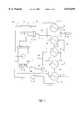
- FIG. 1is a schematic process diagram of the present invention.
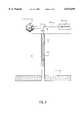
- FIG. 2is a schematic view of one embodiment of the present invention situated on a land location.
- FIG. 3is a schematic view of a second embodiment of the present invention utilizing a coiled tubing unit.
- the novel thermal fluid system 2includes a diesel engine 4.
- the engine 4is used as the heat source. During its operation, the engine 4 will provide as an output a gas exhaust, a water exhaust, and a hydraulic oil exhaust.
- the type of diesel engine used in the preferred embodimentis commercially available and well-known in the art.
- the engine 4will have associated therewith the water exhaust 4 line 6 that leads to the water pump member 8.
- the water pump member 8will then pump the exhaust water to the engine water jacket heat exchanger 10.
- the water heat exchanger 10contains therein a tubular coil (not shown) that is wrapped within the water heat exchanger 10 in a manner well-known in the art.
- a second coil(not shown) is disposed therein.
- the second coilis fluidly connected to a reservoir 12.
- the reservoir 12will contain the treating compound such as acid, solvents or diesel oil which will be described in greater detail later in the application.
- the list of treating compoundsis illustrative.
- the reservoir 12will have a feed line 14 that will be connected to the engine water jacket heat exchanger.
- the feed line 14will connect to the second coil.
- the treating compoundis transferred the latent heat.
- a dual system of heat exchangersis provided as shown in FIG. 1. It should be understood that dual heat exchangers afford an increased capacity for heating the treating compound. Nevertheless, using, only a single heat exchanger is possible.
- the heated waterwill exit the heat exchanger 10 via the feed line 16 and will enter the water jacket heat exchanger 18.
- the treating compoundwill exit the heat exchanger 10 via the feed line 20 and will enter into the heat exchanger 18, and the treating compound will again be transferred heat.
- the heated waterwill then exit the heat exchanger 18 via the feed line 22 and in turn enter the hydraulic heat exchanger 24.
- the treating compoundwill exit the heat exchanger 18 and will be steered into the hydraulic heat exchanger 26 via the feed line 28.
- the treating compoundis directed to the hydraulic heat exchanger 26 and not the hydraulic heat exchanger 24.
- the waterwill then be directed to the exit feed line 29A which has associated therewith a thermostatic valve 29B that controls the opening and closing of valve 29B based on water temperature within line 29A.
- a thermostatic valve 29Bthat controls the opening and closing of valve 29B based on water temperature within line 29A.
- two branchesexit, namely line 29C and 29D.
- the valve 29Bdirects the water to the engine 4 (thereby bypassing the radiator 30).
- the valve 29Bwill direct the water to the radiatior 30 for cooling, and thereafter, to the engine 4.
- the engine 4will have operatively associated therewith the hydraulic pump member 31 as is well understood by those of ordinary skill in the art.
- the hydraulic pump member 31will direct the hydraulic oil to the feed line 32 that in turn leads to a hydraulic back pressure pump 34 used for controlling the back pressure.
- the feed line 36leads to the hydraulic heat exchanger 26.
- the hydraulic oil feed into the hydraulic heat exchanger 26will exit into the hydraulic heat exchanger 24 via the feed line 38.
- the heat exchanger 24has two heated liquids being circulated therein, namely: water and hydraulic oil.
- the hydraulic oilwill exit the heat exchanger 24 via the feed line and empty into the hydraulic oil tank 44.
- the engineduring operation, will also produce an exhaust gas that is derived from the combustion of the hydrocarbon fuel (carbon dioxide).
- the enginehas attached thereto an exhaust gas line 46 that in the preferred embodiment leads to the catalytic converter member 48.
- the feed line 50directs the gas to the exhaust heat exchanger 52 which is similar to the other described heat exchangers, namely 10, 18, 24, 26. The gas will be conducted therethrough.
- the treating compoundwill exit the hydraulic heat exchanger 26 via the feed line 54 and thereafter enter the exhaust heat exchanger 52 for transferring the latent heat of the gas exhaust to the treating compound.
- the gaswill exit via the feed line 56 with the feed line 56 having contained therein the adjustable back pressure orifice control member 58 for controlling the discharge pressure of the gas into the atmosphere.
- the back pressure orifice control member 58is commercially available.
- the feed line 56directs the gas into the muffler and spark arrester 60 for suppressing the noise and any sparks that may be generated from ignition of unspent fuel.
- the gasmay thereafter be discharged into the atmosphere.
- the outlet line 62leads from the exhaust heat exchanger 52.
- the treating compound thus exitingis of sufficient temperature to adequately treat the well bore in the desired manner.
- gyp depositsmay accumulate on the formation face and on downhole equipment and thereby reduce production. These deposits may also form on the internal diameter of the tubing. The deposits may have low solubility and be difficult to remove. Solutions of HCl and EDTA can often be used to remove such scales. Soluble portions of the scale are dissolved by the HCl, and the chelating action of EDTA breaks up and dissolves much of the remaining scale portions.
- a solvent-in-acid blend of aromatic solvents dispersed in HClcan be used to clean the wellbore, downhole equipment, and the first few inches of formation around the wellbore (critical area) through which all fluids must pass to enter the wellbore.
- These blendsare designed as a single stage cleaner that provides the benefits of both an organic solvent and an acid solvent that contact the deposits continuously.
- paraffin removalWith reference to paraffin removal, several good commercial paraffin solvents are on the market. These materials can be circulated past the affected parts of the wellbore or simply dumped into the borehole and allowed to soak opposite the trouble area for a period of time. Soaking, however, is much less effective because the solvent becomes saturated at the point of contact and stagnates.
- Hot-oil treatmentsalso are commonly used to remove paraffin.
- heated oilis pumped down the tubing and into the formation.
- the hot oildissolves the paraffin deposits and carries them out of the well bore when the well is produced.
- hot-oil treatmentsare usually performed on a regularly scheduled basis.
- Paraffin inhibitorsmay also be used. These are designed to create a hydrophilic surface on the metal well equipment. This in turn minimizes the adherence of paraffin accumulations to the treated surfaces.
- Acid treatments to stimulate and/or treat skin damage to the producing formationis also possible with the teachings of the present invention.
- the operatorwould select the correct type of acid, for instance HCl or HF, and thereafter inject the heated compound into the wellbore, and in particular, to the near formation face area.
- FIG. 2a schematic view of one embodiment of the present invention situated on a land location is illustrated.
- the novel thermal fluid system 2is shown in a compact, modular form.
- the system 2is situated adjacent a well head 70, with the well head containing a series of valves.
- the well head 70will be associated with a wellbore 72 that intersects a hydrocarbon reservoir 74.
- the wellbore 72will have disposed therein a tubing string 76 with a packer 78 associated therewith.
- the production of the hydrocarbons from the reservoir 74proceeds through the tubing string 76, through the well head 70 and into the production facilities 80 via the pipeline 82.
- the appropriate treating compoundmay be heated in the novel thermal fluid system 2 as previously described. Thereafter, the heated treating compound may be pumped into the tubing string so as to react with the scale deposit on the internal diameter of the tubing string 76.
- the same methodis employed for parrafin removal.
- the operatormay heat the treating compound in the system 2 as previously described, and thereafter, inject the heated treating compound down the internal diameter of the tubing string 76 and ultimately into the pores of the reservoir so as to react with any fines, clay, slit, and other material that destroys the permeability and/or porosity of the reservoir 74. Still yet another procedure would be to heat a treating compound in the system 2, as previously described, and thereafter inject into the pipeline 82.
- FIG. 3schematic view of a second embodiment of the present invention utilizing a coiled tubing unit 84.
- This particular embodimentdepicts an offshore platform with the coiled tubing unit 84 and the novel thermal fluid system 2 thereon.
- the coiled tubing unit 84 and the thermal system 2may utilize the same power source, which is the engine 4 of the system 2. It should be noted that like numbers appearing in the various figures refer to like components.
- the treating compoundwhich may be a paraffin remover, a scale remover, or acid compound for reservoir stimulation, will be heated in the system 2. Thereafter, the heated treating compound will be injected into the reeled tubing unit 84 and in particular the tubing 86.
- the tubing 86may be lowered to a specified depth and the pumping may begin.
- the tubing 86will have associated therewith an injector head 88. Alternatively, the pumping may begin, and the injector head 88 may be raised and lowered in order to continuously pump the treating compound over a selective interval.
Landscapes
- Geology (AREA)
- Life Sciences & Earth Sciences (AREA)
- Engineering & Computer Science (AREA)
- Mining & Mineral Resources (AREA)
- Environmental & Geological Engineering (AREA)
- Fluid Mechanics (AREA)
- Physics & Mathematics (AREA)
- General Life Sciences & Earth Sciences (AREA)
- Geochemistry & Mineralogy (AREA)
- Production Of Liquid Hydrocarbon Mixture For Refining Petroleum (AREA)
- Exhaust Gas After Treatment (AREA)
- Cleaning Or Drying Semiconductors (AREA)
- Physical Or Chemical Processes And Apparatus (AREA)
Abstract
Description
Claims (13)
Priority Applications (1)
| Application Number | Priority Date | Filing Date | Title |
|---|---|---|---|
| US09/335,213US6073695A (en) | 1996-12-23 | 1999-06-17 | Device and method for treating a well bore |
Applications Claiming Priority (2)
| Application Number | Priority Date | Filing Date | Title |
|---|---|---|---|
| US08/772,314US5988280A (en) | 1996-12-23 | 1996-12-23 | Use of engine heat in treating a well bore |
| US09/335,213US6073695A (en) | 1996-12-23 | 1999-06-17 | Device and method for treating a well bore |
Related Parent Applications (1)
| Application Number | Title | Priority Date | Filing Date |
|---|---|---|---|
| US08/772,314ContinuationUS5988280A (en) | 1996-12-23 | 1996-12-23 | Use of engine heat in treating a well bore |
Publications (1)
| Publication Number | Publication Date |
|---|---|
| US6073695Atrue US6073695A (en) | 2000-06-13 |
Family
ID=25094651
Family Applications (2)
| Application Number | Title | Priority Date | Filing Date |
|---|---|---|---|
| US08/772,314Expired - LifetimeUS5988280A (en) | 1996-12-23 | 1996-12-23 | Use of engine heat in treating a well bore |
| US09/335,213Expired - LifetimeUS6073695A (en) | 1996-12-23 | 1999-06-17 | Device and method for treating a well bore |
Family Applications Before (1)
| Application Number | Title | Priority Date | Filing Date |
|---|---|---|---|
| US08/772,314Expired - LifetimeUS5988280A (en) | 1996-12-23 | 1996-12-23 | Use of engine heat in treating a well bore |
Country Status (8)
| Country | Link |
|---|---|
| US (2) | US5988280A (en) |
| EP (1) | EP1009910A1 (en) |
| AU (1) | AU5717198A (en) |
| BR (1) | BR9714175A (en) |
| CA (1) | CA2276048A1 (en) |
| ID (1) | ID22386A (en) |
| NO (1) | NO993117L (en) |
| WO (1) | WO1998028520A1 (en) |
Cited By (15)
| Publication number | Priority date | Publication date | Assignee | Title |
|---|---|---|---|---|
| US6415866B1 (en) | 2000-03-07 | 2002-07-09 | Benton F. Baugh | Thermal operating module with scavenger system |
| US6820689B2 (en) | 2002-07-18 | 2004-11-23 | Production Resources, Inc. | Method and apparatus for generating pollution free electrical energy from hydrocarbons |
| US20060110218A1 (en)* | 2004-11-23 | 2006-05-25 | Thermal Remediation Services | Electrode heating with remediation agent |
| US20060266152A1 (en)* | 2005-05-26 | 2006-11-30 | Armstrong Ray G | One lever tilt and telescope mechanism |
| US20100000508A1 (en)* | 2008-07-07 | 2010-01-07 | Chandler Ronald L | Oil-fired frac water heater |
| US20100071899A1 (en)* | 2008-09-22 | 2010-03-25 | Laurent Coquilleau | Wellsite Surface Equipment Systems |
| US20100243639A1 (en)* | 2009-03-24 | 2010-09-30 | Beyke Gregory L | Flexible horizontal electrode pipe |
| US20110005757A1 (en)* | 2010-03-01 | 2011-01-13 | Jeff Hebert | Device and method for flowing back wellbore fluids |
| US20110061873A1 (en)* | 2008-02-22 | 2011-03-17 | Conocophillips Company | Hydraulically Driven Downhole Pump Using Multi-Channel Coiled Tubing |
| JP5173057B1 (en)* | 2012-08-29 | 2013-03-27 | 新日鉄住金エンジニアリング株式会社 | Multiple pipes and systems for steam recovery from geothermal wells. |
| US9322571B2 (en) | 2011-11-11 | 2016-04-26 | Lv Dynamics Llc | Heating system having plasma heat exchanger |
| US9347303B2 (en) | 2011-04-08 | 2016-05-24 | Amcol International Corporation | Produced fluid heating and separation |
| US9932799B2 (en) | 2015-05-20 | 2018-04-03 | Canadian Oilfield Cryogenics Inc. | Tractor and high pressure nitrogen pumping unit |
| US11642709B1 (en) | 2021-03-04 | 2023-05-09 | Trs Group, Inc. | Optimized flux ERH electrode |
| US11979950B2 (en) | 2020-02-18 | 2024-05-07 | Trs Group, Inc. | Heater for contaminant remediation |
Families Citing this family (20)
| Publication number | Priority date | Publication date | Assignee | Title |
|---|---|---|---|---|
| US5979549A (en)* | 1997-10-29 | 1999-11-09 | Meeks; Thomas | Method and apparatus for viscosity reduction of clogging hydrocarbons in oil well |
| US6165368A (en)* | 1998-08-19 | 2000-12-26 | Valero Energy Corporation | Method of controlling deposition of foulants in processing equipment used to process products streams produced by the dehydrogenation of aliphatic hydrocarbons |
| US7765794B2 (en)* | 2001-05-04 | 2010-08-03 | Nco2 Company Llc | Method and system for obtaining exhaust gas for use in augmenting crude oil production |
| US6893615B1 (en) | 2001-05-04 | 2005-05-17 | Nco2 Company Llc | Method and system for providing substantially water-free exhaust gas |
| US20080206699A1 (en)* | 2003-03-07 | 2008-08-28 | St Denis Perry Lucien | Method and apparatus for heating a liquid storage tank |
| CA2421384C (en)* | 2003-03-07 | 2009-12-15 | Ici Solutions Inc. | Method and apparatus for heating a liquid storage tank |
| CA2427410A1 (en)* | 2003-05-01 | 2004-11-01 | Leader Energy Services Corp. | Flameless hot oiler |
| US7445761B1 (en) | 2003-05-02 | 2008-11-04 | Alexander Wade J | Method and system for providing compressed substantially oxygen-free exhaust gas for industrial purposes |
| US20130075245A1 (en) | 2009-12-16 | 2013-03-28 | F. Alan Frick | Methods and systems for heating and manipulating fluids |
| US7614367B1 (en) | 2006-05-15 | 2009-11-10 | F. Alan Frick | Method and apparatus for heating, concentrating and evaporating fluid |
| US10039996B2 (en) | 2006-04-24 | 2018-08-07 | Phoenix Callente LLC | Methods and systems for heating and manipulating fluids |
| US8371251B2 (en)* | 2006-04-24 | 2013-02-12 | Phoenix Caliente Llc | Methods and apparatuses for heating, concentrating and evaporating fluid |
| CA2615347A1 (en)* | 2007-12-18 | 2009-06-18 | Melvin Kohlman | Heat tube assembly |
| US7703528B2 (en)* | 2008-01-15 | 2010-04-27 | Halliburton Energy Services, Inc. | Reducing CO2 emissions from oilfield diesel engines |
| CA2691389A1 (en)* | 2010-01-28 | 2011-07-28 | Grant W. Hiebert | Method and apparatus for heating bitumen slurry stored in a tank |
| US8978769B2 (en)* | 2011-05-12 | 2015-03-17 | Richard John Moore | Offshore hydrocarbon cooling system |
| CA2741581C (en) | 2011-05-26 | 2015-02-17 | Newco Tank Corp. | Method and apparatus for heating a sales tank |
| US20130014950A1 (en)* | 2011-07-14 | 2013-01-17 | Dickinson Theodore Elliot | Methods of Well Cleanout, Stimulation and Remediation and Thermal Convertor Assembly for Accomplishing Same |
| US9802459B2 (en) | 2012-12-21 | 2017-10-31 | Multitek North America, Llc | Self-contained flameless fluid heating system |
| US10107455B2 (en) | 2013-11-20 | 2018-10-23 | Khaled Shaaban | LNG vaporization |
Citations (20)
| Publication number | Priority date | Publication date | Assignee | Title |
|---|---|---|---|---|
| US2823752A (en)* | 1955-08-30 | 1958-02-18 | Worthington Corp | Method and arrangement of apparatus for oil recovery |
| US3066737A (en)* | 1959-02-24 | 1962-12-04 | Isaac B Barrett | Flue gas well casing pressure cycling system and apparatus |
| US3522843A (en)* | 1968-03-12 | 1970-08-04 | Robert V New | Apparatus for production amplification by stimulated emission of radiation |
| US3833059A (en)* | 1973-02-12 | 1974-09-03 | Motco Inc | Hot gas apparatus for recovery of oil values |
| US4044549A (en)* | 1972-12-11 | 1977-08-30 | Zwick Eugene B | Low emission combustion process and apparatus |
| US4197712A (en)* | 1978-04-21 | 1980-04-15 | Brigham William D | Fluid pumping and heating system |
| US4255116A (en)* | 1975-09-22 | 1981-03-10 | Zwick Eugene B | Prevaporizing burner and method |
| US4290271A (en)* | 1980-03-06 | 1981-09-22 | Waukesha-Pearce Industries, Inc. | Nitrogen liquid to gas converter |
| US4373896A (en)* | 1978-10-31 | 1983-02-15 | Zwick Eugene B | Burner construction |
| US4472946A (en)* | 1983-01-28 | 1984-09-25 | Zwick Eugene B | Cryogenic storage tank with built-in pump |
| US4480695A (en)* | 1982-08-31 | 1984-11-06 | Chevron Research Company | Method of assisting surface lift of heated subsurface viscous petroleum |
| US4546610A (en)* | 1975-09-22 | 1985-10-15 | Zwick Eugene B | Prevaporizing combustion method |
| US4655285A (en)* | 1985-03-06 | 1987-04-07 | Spitzer William R | Plug for use in hot oil treatment of wells having paraffin deposits and method of use thereof |
| US4860545A (en)* | 1988-11-07 | 1989-08-29 | Zwick Energy Research Organization, Inc. | Cryogenic storage tank with a retrofitted in-tank cryogenic pump |
| US4924679A (en)* | 1989-10-02 | 1990-05-15 | Zwick Energy Research Organization, Inc. | Apparatus and method for evacuating an insulated cryogenic hose |
| US5215454A (en)* | 1991-08-26 | 1993-06-01 | Zwick Energy Research Organization, Inc. | Buzz suppression in burners of high capacity direct fired fluid heaters |
| US5242133A (en)* | 1990-12-28 | 1993-09-07 | Zwick Eugene B | Method and apparatus for heating and delivering deicing fluids |
| US5335728A (en)* | 1992-07-31 | 1994-08-09 | Strahan Ronald L | Method and apparatus for disposing of water at gas wells |
| US5388650A (en)* | 1993-06-14 | 1995-02-14 | Generon Systems | Non-cryogenic production of nitrogen for on-site injection in downhole drilling |
| US5656136A (en)* | 1993-11-12 | 1997-08-12 | Pool Company | Method of transporting and heating a liquid used for treating oil and gas wells or pipeline systems |
Family Cites Families (7)
| Publication number | Priority date | Publication date | Assignee | Title |
|---|---|---|---|---|
| US3156299A (en)* | 1963-01-07 | 1964-11-10 | Phillips Petroleum Co | Subterranean chemical process |
| US3658270A (en)* | 1970-06-10 | 1972-04-25 | Bowen Tools Inc | Well tubing injector and removal apparatus |
| US4454917A (en)* | 1979-11-06 | 1984-06-19 | Carmel Energy, Inc. | Thermal acidization and recovery process for recovering viscous petroleum |
| US4589488A (en)* | 1982-03-30 | 1986-05-20 | Phillips Petroleum Company | Method for recovery of mineral resources |
| US4882009A (en)* | 1987-07-13 | 1989-11-21 | Four Nines, Inc. | Apparatus for concentrating brine waters or dewatering brines generated in well drilling operation |
| US5056315A (en)* | 1989-10-17 | 1991-10-15 | Jenkins Peter E | Compounded turbocharged rotary internal combustion engine fueled with natural gas |
| US5011329A (en)* | 1990-02-05 | 1991-04-30 | Hrubetz Exploration Company | In situ soil decontamination method and apparatus |
- 1996
- 1996-12-23USUS08/772,314patent/US5988280A/ennot_activeExpired - Lifetime
- 1997
- 1997-12-19EPEP97953419Apatent/EP1009910A1/ennot_activeWithdrawn
- 1997-12-19IDIDW990734Dpatent/ID22386A/enunknown
- 1997-12-19AUAU57171/98Apatent/AU5717198A/ennot_activeAbandoned
- 1997-12-19CACA002276048Apatent/CA2276048A1/ennot_activeAbandoned
- 1997-12-19BRBR9714175-5Apatent/BR9714175A/ennot_activeApplication Discontinuation
- 1997-12-19WOPCT/US1997/023804patent/WO1998028520A1/ennot_activeApplication Discontinuation
- 1999
- 1999-06-17USUS09/335,213patent/US6073695A/ennot_activeExpired - Lifetime
- 1999-06-23NONO993117Apatent/NO993117L/ennot_activeApplication Discontinuation
Patent Citations (22)
| Publication number | Priority date | Publication date | Assignee | Title |
|---|---|---|---|---|
| US2823752A (en)* | 1955-08-30 | 1958-02-18 | Worthington Corp | Method and arrangement of apparatus for oil recovery |
| US3066737A (en)* | 1959-02-24 | 1962-12-04 | Isaac B Barrett | Flue gas well casing pressure cycling system and apparatus |
| US3522843A (en)* | 1968-03-12 | 1970-08-04 | Robert V New | Apparatus for production amplification by stimulated emission of radiation |
| US4044549A (en)* | 1972-12-11 | 1977-08-30 | Zwick Eugene B | Low emission combustion process and apparatus |
| US3833059A (en)* | 1973-02-12 | 1974-09-03 | Motco Inc | Hot gas apparatus for recovery of oil values |
| US4255116A (en)* | 1975-09-22 | 1981-03-10 | Zwick Eugene B | Prevaporizing burner and method |
| US4546610A (en)* | 1975-09-22 | 1985-10-15 | Zwick Eugene B | Prevaporizing combustion method |
| US4197712A (en)* | 1978-04-21 | 1980-04-15 | Brigham William D | Fluid pumping and heating system |
| US4373896A (en)* | 1978-10-31 | 1983-02-15 | Zwick Eugene B | Burner construction |
| US4290271A (en)* | 1980-03-06 | 1981-09-22 | Waukesha-Pearce Industries, Inc. | Nitrogen liquid to gas converter |
| US4480695A (en)* | 1982-08-31 | 1984-11-06 | Chevron Research Company | Method of assisting surface lift of heated subsurface viscous petroleum |
| US4472946A (en)* | 1983-01-28 | 1984-09-25 | Zwick Eugene B | Cryogenic storage tank with built-in pump |
| US4655285A (en)* | 1985-03-06 | 1987-04-07 | Spitzer William R | Plug for use in hot oil treatment of wells having paraffin deposits and method of use thereof |
| US4860545A (en)* | 1988-11-07 | 1989-08-29 | Zwick Energy Research Organization, Inc. | Cryogenic storage tank with a retrofitted in-tank cryogenic pump |
| US4924679A (en)* | 1989-10-02 | 1990-05-15 | Zwick Energy Research Organization, Inc. | Apparatus and method for evacuating an insulated cryogenic hose |
| US5242133A (en)* | 1990-12-28 | 1993-09-07 | Zwick Eugene B | Method and apparatus for heating and delivering deicing fluids |
| US5282590A (en)* | 1990-12-28 | 1994-02-01 | Zwick Eugene B | Method and apparatus for heating and delivering deicing fluids |
| US5215454A (en)* | 1991-08-26 | 1993-06-01 | Zwick Energy Research Organization, Inc. | Buzz suppression in burners of high capacity direct fired fluid heaters |
| US5335728A (en)* | 1992-07-31 | 1994-08-09 | Strahan Ronald L | Method and apparatus for disposing of water at gas wells |
| US5388650A (en)* | 1993-06-14 | 1995-02-14 | Generon Systems | Non-cryogenic production of nitrogen for on-site injection in downhole drilling |
| US5388650B1 (en)* | 1993-06-14 | 1997-09-16 | Mg Nitrogen Services Inc | Non-cryogenic production of nitrogen for on-site injection in downhole drilling |
| US5656136A (en)* | 1993-11-12 | 1997-08-12 | Pool Company | Method of transporting and heating a liquid used for treating oil and gas wells or pipeline systems |
Non-Patent Citations (2)
| Title |
|---|
| Walker, et al. "Heated Acid for Improved Stimulation Results," SPE # 13371, Oct. 31, 1984, pp. 159-163. |
| Walker, et al. Heated Acid for Improved Stimulation Results, SPE 13371, Oct. 31, 1984, pp. 159 163.* |
Cited By (22)
| Publication number | Priority date | Publication date | Assignee | Title |
|---|---|---|---|---|
| US6415866B1 (en) | 2000-03-07 | 2002-07-09 | Benton F. Baugh | Thermal operating module with scavenger system |
| US6820689B2 (en) | 2002-07-18 | 2004-11-23 | Production Resources, Inc. | Method and apparatus for generating pollution free electrical energy from hydrocarbons |
| US20060054318A1 (en)* | 2002-07-18 | 2006-03-16 | Sarada Steven A | Method and apparatus for generating pollution free electrical energy from hydrocarbons |
| US7290959B2 (en)* | 2004-11-23 | 2007-11-06 | Thermal Remediation Services | Electrode heating with remediation agent |
| US20060110218A1 (en)* | 2004-11-23 | 2006-05-25 | Thermal Remediation Services | Electrode heating with remediation agent |
| US7503234B2 (en) | 2005-05-26 | 2009-03-17 | Delphi Technologies, Inc. | One lever tilt and telescope mechanism |
| US20060266152A1 (en)* | 2005-05-26 | 2006-11-30 | Armstrong Ray G | One lever tilt and telescope mechanism |
| US20110061873A1 (en)* | 2008-02-22 | 2011-03-17 | Conocophillips Company | Hydraulically Driven Downhole Pump Using Multi-Channel Coiled Tubing |
| US8534235B2 (en) | 2008-07-07 | 2013-09-17 | Ronald L. Chandler | Oil-fired frac water heater |
| US20100000508A1 (en)* | 2008-07-07 | 2010-01-07 | Chandler Ronald L | Oil-fired frac water heater |
| US9062546B2 (en) | 2008-07-07 | 2015-06-23 | Ronald L. Chandler | Method for heating treatment fluid using an oil-fired frac water heater |
| US20100071899A1 (en)* | 2008-09-22 | 2010-03-25 | Laurent Coquilleau | Wellsite Surface Equipment Systems |
| US20100243639A1 (en)* | 2009-03-24 | 2010-09-30 | Beyke Gregory L | Flexible horizontal electrode pipe |
| US20110005757A1 (en)* | 2010-03-01 | 2011-01-13 | Jeff Hebert | Device and method for flowing back wellbore fluids |
| US9347303B2 (en) | 2011-04-08 | 2016-05-24 | Amcol International Corporation | Produced fluid heating and separation |
| US9469552B2 (en) | 2011-04-08 | 2016-10-18 | Amcol International Corporation | Produced fluid heating and separation |
| US9322571B2 (en) | 2011-11-11 | 2016-04-26 | Lv Dynamics Llc | Heating system having plasma heat exchanger |
| JP5173057B1 (en)* | 2012-08-29 | 2013-03-27 | 新日鉄住金エンジニアリング株式会社 | Multiple pipes and systems for steam recovery from geothermal wells. |
| US9470434B2 (en) | 2012-08-29 | 2016-10-18 | Nippon Steel & Sumikin Engineering Co., Ltd. | Multiplex pipe and system for recovering steam from geothermal wells |
| US9932799B2 (en) | 2015-05-20 | 2018-04-03 | Canadian Oilfield Cryogenics Inc. | Tractor and high pressure nitrogen pumping unit |
| US11979950B2 (en) | 2020-02-18 | 2024-05-07 | Trs Group, Inc. | Heater for contaminant remediation |
| US11642709B1 (en) | 2021-03-04 | 2023-05-09 | Trs Group, Inc. | Optimized flux ERH electrode |
Also Published As
| Publication number | Publication date |
|---|---|
| BR9714175A (en) | 2000-02-29 |
| WO1998028520A1 (en) | 1998-07-02 |
| US5988280A (en) | 1999-11-23 |
| ID22386A (en) | 1999-10-07 |
| NO993117L (en) | 1999-08-10 |
| NO993117D0 (en) | 1999-06-23 |
| CA2276048A1 (en) | 1998-07-02 |
| EP1009910A1 (en) | 2000-06-21 |
| AU5717198A (en) | 1998-07-17 |
Similar Documents
| Publication | Publication Date | Title |
|---|---|---|
| US6073695A (en) | Device and method for treating a well bore | |
| US4456069A (en) | Process and apparatus for treating hydrocarbon-bearing well formations | |
| US20090308613A1 (en) | Method and apparatus to treat a well with high energy density fluid | |
| US20110005757A1 (en) | Device and method for flowing back wellbore fluids | |
| US8651187B2 (en) | Method and apparatus to treat well stimulation fluids in-situ | |
| US5400430A (en) | Method for injection well stimulation | |
| US6588500B2 (en) | Enhanced oil well production system | |
| AU738120B2 (en) | Apparatus for viscosity reduction of clogging hydrocarbons in an oil well | |
| ATE276425T1 (en) | METHOD FOR CAPSULATING FLUID IN PETROLEUM RESERVES | |
| CA1193185A (en) | Thermally stimulating well production | |
| US8424608B1 (en) | System and method for remediating hydrates | |
| US20130014950A1 (en) | Methods of Well Cleanout, Stimulation and Remediation and Thermal Convertor Assembly for Accomplishing Same | |
| US7896978B2 (en) | Thermal fluid stimulation unit | |
| US20120174987A1 (en) | Flameless heating system | |
| CN101641493A (en) | Downhole Series Heater | |
| US4911240A (en) | Self treating paraffin removing apparatus and method | |
| US6415866B1 (en) | Thermal operating module with scavenger system | |
| RU2168619C1 (en) | Method of heat treatment of bottom-hole zone of oil-gas well | |
| Esaklul et al. | Active heating for flow assurance control in deepwater flowlines | |
| MXPA99005978A (en) | Device and method for heating a treating fluid | |
| US20140290952A1 (en) | Flameless Heating Method | |
| SU889834A1 (en) | Method of metering-out an agent into a well | |
| RU1781417C (en) | Process of decomposition of paraffin-resinous deposits and device to implement it | |
| RU2114281C1 (en) | Method for elimination of asphaltic-resin-paraffin depositions in high-temperature wells | |
| CN117927189A (en) | Method for applying scale inhibitor to completion fluid during injection testing operation |
Legal Events
| Date | Code | Title | Description |
|---|---|---|---|
| STCF | Information on status: patent grant | Free format text:PATENTED CASE | |
| AS | Assignment | Owner name:GENERAL ELECTRIC CAPITAL CORPORATION, NEW YORK Free format text:SECURITY INTEREST;ASSIGNOR:CARDINAL SERVICES, INC.;REEL/FRAME:011122/0388 Effective date:20000726 | |
| AS | Assignment | Owner name:CARDINAL SERVICES, INC., LOUISIANA Free format text:ASSIGNMENT OF ASSIGNORS INTEREST;ASSIGNOR:AMBAR, INC.;REEL/FRAME:011058/0633 Effective date:20000726 | |
| AS | Assignment | Owner name:SUPERIOR ENERGY SERVICES, L.L.C., LOUISIANA Free format text:MERGER;ASSIGNOR:SUPERIOR WELL SERVICE, INC.;REEL/FRAME:011571/0929 Effective date:20001218 Owner name:SUPERIOR WELL SERVICE, INC., LOUISIANA Free format text:MERGER;ASSIGNOR:CARDINAL SERVICES, INC.;REEL/FRAME:011571/0938 Effective date:20001218 | |
| FEPP | Fee payment procedure | Free format text:PAT HOLDER NO LONGER CLAIMS SMALL ENTITY STATUS, ENTITY STATUS SET TO UNDISCOUNTED (ORIGINAL EVENT CODE: STOL); ENTITY STATUS OF PATENT OWNER: LARGE ENTITY | |
| REFU | Refund | Free format text:REFUND - SURCHARGE, PETITION TO ACCEPT PYMT AFTER EXP, UNINTENTIONAL (ORIGINAL EVENT CODE: R2551); ENTITY STATUS OF PATENT OWNER: LARGE ENTITY | |
| FPAY | Fee payment | Year of fee payment:4 | |
| FPAY | Fee payment | Year of fee payment:8 | |
| FPAY | Fee payment | Year of fee payment:12 | |
| AS | Assignment | Owner name:JPMORGAN CHASE BANK, N.A., AS ADMINISTRATIVE AGENT Free format text:AMENDED AND RESTATED SECURITY AGREEMENT;ASSIGNORS:CONNECTION TECHNOLOGY, L.L.C.;FASTORQ, L.L.C.;PRODUCTION MANAGEMENT INDUSTRIES, L.L.C.;AND OTHERS;REEL/FRAME:027793/0211 Effective date:20120207 |