Movatterモバイル変換


[0]ホーム

URL:


US6072729A - Data-output driver circuit and method - Google Patents

Data-output driver circuit and method
Download PDF

Info

Publication number
US6072729A
US6072729AUS09/138,861US13886198AUS6072729AUS 6072729 AUS6072729 AUS 6072729AUS 13886198 AUS13886198 AUS 13886198AUS 6072729 AUS6072729 AUS 6072729A
Authority
US
United States
Prior art keywords
drive
transistor
terminal
coupled
inverter
Prior art date
Legal status (The legal status is an assumption and is not a legal conclusion. Google has not performed a legal analysis and makes no representation as to the accuracy of the status listed.)
Ceased
Application number
US09/138,861
Inventor
Stephen L. Casper
Current Assignee (The listed assignees may be inaccurate. Google has not performed a legal analysis and makes no representation or warranty as to the accuracy of the list.)
Micron Technology Inc
Original Assignee
Micron Technology Inc
Priority date (The priority date is an assumption and is not a legal conclusion. Google has not performed a legal analysis and makes no representation as to the accuracy of the date listed.)
Filing date
Publication date
Application filed by Micron Technology IncfiledCriticalMicron Technology Inc
Priority to US09/138,861priorityCriticalpatent/US6072729A/en
Assigned to MICRON TECHNOLOGY, INC.reassignmentMICRON TECHNOLOGY, INC.ASSIGNMENT OF ASSIGNORS INTEREST (SEE DOCUMENT FOR DETAILS).Assignors: CASPER, STEPHEN L.
Application grantedgrantedCritical
Publication of US6072729ApublicationCriticalpatent/US6072729A/en
Priority to US10/164,354prioritypatent/USRE38685E1/en
Assigned to U.S. BANK NATIONAL ASSOCIATION, AS COLLATERAL AGENTreassignmentU.S. BANK NATIONAL ASSOCIATION, AS COLLATERAL AGENTSECURITY INTEREST (SEE DOCUMENT FOR DETAILS).Assignors: MICRON TECHNOLOGY, INC.
Assigned to MORGAN STANLEY SENIOR FUNDING, INC., AS COLLATERAL AGENTreassignmentMORGAN STANLEY SENIOR FUNDING, INC., AS COLLATERAL AGENTPATENT SECURITY AGREEMENTAssignors: MICRON TECHNOLOGY, INC.
Assigned to U.S. BANK NATIONAL ASSOCIATION, AS COLLATERAL AGENTreassignmentU.S. BANK NATIONAL ASSOCIATION, AS COLLATERAL AGENTCORRECTIVE ASSIGNMENT TO CORRECT THE REPLACE ERRONEOUSLY FILED PATENT #7358718 WITH THE CORRECT PATENT #7358178 PREVIOUSLY RECORDED ON REEL 038669 FRAME 0001. ASSIGNOR(S) HEREBY CONFIRMS THE SECURITY INTEREST.Assignors: MICRON TECHNOLOGY, INC.
Assigned to JPMORGAN CHASE BANK, N.A., AS COLLATERAL AGENTreassignmentJPMORGAN CHASE BANK, N.A., AS COLLATERAL AGENTSECURITY INTEREST (SEE DOCUMENT FOR DETAILS).Assignors: MICRON SEMICONDUCTOR PRODUCTS, INC., MICRON TECHNOLOGY, INC.
Assigned to MICRON TECHNOLOGY, INC.reassignmentMICRON TECHNOLOGY, INC.RELEASE BY SECURED PARTY (SEE DOCUMENT FOR DETAILS).Assignors: U.S. BANK NATIONAL ASSOCIATION, AS COLLATERAL AGENT
Anticipated expirationlegal-statusCritical
Assigned to MICRON TECHNOLOGY, INC.reassignmentMICRON TECHNOLOGY, INC.RELEASE BY SECURED PARTY (SEE DOCUMENT FOR DETAILS).Assignors: MORGAN STANLEY SENIOR FUNDING, INC., AS COLLATERAL AGENT
Assigned to MICRON TECHNOLOGY, INC., MICRON SEMICONDUCTOR PRODUCTS, INC.reassignmentMICRON TECHNOLOGY, INC.RELEASE BY SECURED PARTY (SEE DOCUMENT FOR DETAILS).Assignors: JPMORGAN CHASE BANK, N.A., AS COLLATERAL AGENT
Ceasedlegal-statusCriticalCurrent

Links

Images

Classifications

Definitions

Landscapes

Abstract

A drive circuit includes drive input and output terminals, a supply terminal, a drive transistor, and a drive-control circuit. The drive transistor includes a control terminal, a first transistor terminal coupled to the drive output terminal, and a second transistor terminal coupled to the supply terminal. The drive-control circuit has an input terminal coupled to the drive input terminal and has an output terminal coupled to the control terminal of the drive transistor. The drive-control circuit generates on the control terminal of the drive transistor a signal level that changes at a first rate during a first time period and at a second higher rate during a second time period following the first time period. As a result, when used as a data-output driver, one can adjust the first and second rates and time periods such that the drive circuit meets both the 50-ohm and 50 pf falling-slew-rate ranges specified in the Intel TM PC-100 specification.

Description

TECHNICAL FIELD
The invention relates generally to integrated circuits and, more particularly, to a data-output driver circuit having an improved slew-rate characteristic.
BACKGROUND OF THE INVENTION
Today's engineers often design electronic systems so that they will function properly when a component from one manufacturer is replaced with a like component from another manufacturer. For example, most personal computers will function properly with a Pentium® processor from Intel or a K6® processor from Advanced Micro Devices (AMD). This interchangeability of components provides many advantages. For example, because more than one manufacturer can source a particular component, competition among manufacturers is increased, thus lowering the cost per component. Furthermore, if one manufacturer runs out of a particular component, the system manufacturer can obtain like components from another manufacturer and thus avoid a production delay. Additionally, for systems such as personal computers, such interchangeability provides greater flexibility to a customer by allowing him to select components that meet his quality, performance, and cost expectations.
To allow component interchangeability, a system designer often specifies the operating characteristics and parameters that a component must meet in order to function in a particular system. Thus, if a manufacturer wants to design a component of the system, then it must design the component to meet these system specifications.
Table 1 at the end of the specification is a section of Intel's PC-100 specification for Synchronous Dynamic Random Access Memories (SDRAMs) designed for use on Intel's computer boards. Specifically, this section specifies the acceptable ranges of the rise- and fall-time slew rates (Volts/nanosecond) into 50-ohm and 50 picofarad (pf) loads, respectively, and the push (switching current high) and pull (switching current low) drive currents for an SDRAM's data output drivers. These drivers, which are called DQ drivers, are the circuits that drive the data onto the data bus during a read cycle. Unfortunately, conventional DQ drivers often cannot meet all the requirements of the PC-100 specification.
FIG. 1 is a schematic diagram of aconventional DQ driver 10, which drives adata output terminal 11 of an SDRAM. During a read cycle, thedriver 10 receives a DATA IN signal from a selected memory cell (not shown) on aninput terminal 12, and receives its complement DATA IN on aninput terminal 13. Thus, when DATA IN islogic 1, DATA IN islogic 0, and vice versa. A conventional voltage-boost circuit 14 controls an NMOS pull-up transistor 16 in response to DATA IN. Thecircuit 14 receives a boost voltage VBOOST, which is typically at least one threshold voltage of thetransistor 16 above VDD. When DATA IN islogic 1, thecircuit 14 applies VBOOST to the gate of thetransistor 16, thus overdriving thetransistor 16 so that it fully couples VDD to theoutput terminal 11. Aconventional inverter 18, which includes aPMOS transistor 20 and anNMOS transistor 22, controls an NMOS pull-down transistor 24 in response to DATA IN. When DATA IN islogic 1, thetransistor 22 deactivates thetransistor 24 by pulling its gate to VSS, which is typically ground. Conversely, when DATA IN islogic 0, thetransistor 20 activates thetransistor 24 by pulling its gate to VDD. Because thetransistor 24 often has a relatively high input capacitance, the channel-width/channel-length ratio, and thus the gain, of thetransistor 20 is made relatively high. This allows thetransistor 20 to source the relatively large activation current required to quickly charge the input capacitance and thus quickly turn on thetransistor 24.
Unfortunately, although theDQ driver 10 meets most of the PC-100 specifications in Table 1, it may not meet all of them. In operation, theboost circuit 14 controls the pull-up transistor 16 such that thedriver 10 does generate the rising slew rates within the specified ranges when a 50-ohm load and a 50 pf load are respectively connected between theoutput terminal 11 and VSS. Thedriver 10 also meets the push drive-current specification, which means that thetransistor 16 sources current within the specified range when theoutput terminal 11 is at 1.65 V. But unfortunately, although thetransistor 20 drives thetransistor 24 such thatdriver 10 meets the pull drive-current specification, thedriver 10 may not meet one of the 50-ohm and 50 pf falling slew-rate specifications as discussed below.
An embodiment of thedriver 10 that meets one but misses the other falling slew-rate specification will now be discussed with reference to FIGS. 2 and 3 and Table 1. FIG. 2 is a graph showing the falling slew rate into a 50 pf load for thedriver 10. Here, the gain of thetransistor 20 is such that thetransistor 24 generates a 50 pf falling slew rate of approximately 3.5 V/nS within the specifiedregion 26 of between 1.2 and 1.8 V. Referring to Table 1, this 50 pf falling slew rate is within the specified range of 1.3-3.6 V/ns.
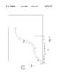
 FIG. 3 is a graph of the falling slew rate into a 50-ohm load for the same embodiment of thedriver 10. Here, the gain of thetransistor 20 is such that thetransistor 24 generates a 50-ohm falling slew rate of approximately 16 V/nS within the specifiedregion 26. Referring to Table 1, however, this 50-ohm falling slew rate is well above the maximum specified slew rate of 5 V/nS.
The problem with this embodiment of thedriver 10 is that the gain of thetransistor 20, which is set high enough for thedriver 10 to meet the 50 pf falling slew-rate specification, causes thedriver 10 to exceed the 50-ohm falling slew-rate specification. Unfortunately, reducing the gain of thetransistor 20 so that thedriver 10 meets the 50-ohm falling slew-rate specification causes thedriver 10 to undershoot the 50 pf falling slew-rate specification.
SUMMARY OF THE INVENTION
In one aspect of the invention, a drive circuit includes drive input and output terminals, a supply terminal, a drive transistor, and a drive-control circuit. The drive transistor includes a control terminal, a first transistor terminal coupled to the drive output terminal, and a second transistor terminal coupled to the supply terminal. The drive-control circuit has an input terminal coupled to the drive input terminal and has an output terminal coupled to the control terminal of the drive transistor. The drive-control circuit generates on the control terminal of the drive transistor a signal level that changes at a first rate during a first time period and changes at a second, higher rate during a second time period following the first time period.
One can adjust the first and second rates and the first and second time periods such that the drive circuit meets both the 50-ohm and 50 pf falling slew rates specified in the PC-100 specification.
BRIEF DESCRIPTION OF THE DRAWINGS
FIG. 1 is a schematic diagram of a conventional data-output drive circuit.
FIG. 2 is a graph showing the 50 pf falling slew rate of the drive circuit of FIG. 1.
FIG. 3 is a graph showing the 50-ohm falling slew rate of the drive circuit of FIG. 1.
FIG. 4 is a schematic diagram of a data-output drive circuit according to an embodiment of the invention.
FIG. 5 is a graph showing a drive-transistor control signal generated by the drive-control circuit of FIG. 4.
FIG. 6 is a graph showing the 50 pf falling slew rate of the drive circuit of FIG. 4.
FIG. 7 is a graph showing the 50-ohm falling slew rate of the drive circuit of FIG. 4.
FIG. 8 is a schematic block diagram of an embodiment of a memory circuit that incorporates the drive circuit of FIG. 4.
FIG. 9 is a schematic block diagram of an embodiment of an electronic system that incorporates the memory circuit of FIG. 8.
DETAILED DESCRIPTION OF THE INVENTION
FIG. 4 is a schematic diagram of aDQ drive circuit 30 according to an embodiment of the invention, with like numerals representing like components of thedrive circuit 10 of FIG. 1. Thedrive circuit 30 includes theboost circuit 14, pull-up transistor 16, and pull-downtransistor 24, which are constructed and which operate similarly to the same components of thedrive circuit 10. But unlike thedrive circuit 10, thedrive circuit 30 also includes a drive-control circuit 32, which drives thetransistor 24. Generally, thecircuit 32 generates a multi-slope control signal that allows thetransistor 24 to generate 50-ohm and 50 pf falling slew rates that meet the PC-100 specification.
More specifically, the drive-control circuit 32 includes a first drive-control stage 36, which during a first time period generates a first portion of the control signal having a first slope characteristic on the gate of thetransistor 24 via aline 38. Thecircuit 32 also includes a second drive-control stage 40, which generates a second portion of the control signal having a second slope characteristic on theline 38 during a second time period that follows the first time period. Additionally, aswitch 42 may be included to cut off power to a portion of thesecond stage 40 when the input data signal transitions tologic 1. This significantly speeds up the turn-off time of thesecond stage 40. In one embodiment, theswitch 42 is a PMOS transistor.
In one embodiment, thefirst stage 36 is an inverter that includes a PMOS pull-up transistor 44 and an NMOS pull-down transistor 46. Thetransistor 44 is sized such that during the first time period when DATA IN islogic 0, thetransistor 44 causes a control voltage on theline 38 to rise according to a first rate characteristic. Thesecond stage 40 includes asecond inverter 48, which includes a PMOS pull-up transistor 50 and an NMOS pull-down transistor 52, and aPMOS transistor 54 having its gate coupled to the output of theinverter 48. During the second time period when DATA IN islogic 0, theinverter 48 controls thetransistor 54 such that it causes the control voltage on theline 38 to rise according to a second rate characteristic, which in one embodiment is steeper than the first rate characteristic. As stated above, by properly adjusting the first and second rate characteristics during the respective first and second time periods, the drive-control circuit 32 controls thetransistor 24 such that thedrive circuit 30 meets the PC-100 50 pf and 50-ohm falling slew-rate specifications. For example, in one embodiment as discussed below, setting the gain of thetransistor 54 to be two or more times the gain of thetransistor 44 allows thedrive circuit 30 to meet all of the PC-100 specifications.
In operation, referring to FIG. 4, when DATA IN islogic 1, thetransistor 46 deactivates thetransistor 24 by pulling its gate to VSS, which is ground in this embodiment. Thelogic 1 DATA IN also deactivates theswitch 42, which cuts off power to thetransistor 54. Thetransistor 46 pulls the input of theinverter 48 to ground, thus activating thetransistor 50 and deactivating thetransistor 52. Theactive transistor 50 deactivates thetransistor 54 by pulling its gate to VDD. Therefore, whether or not thedrive circuit 30 includes theswitch 42, thetransistor 54 is disabled from driving a signal onto theline 38. Furthermore, as discussed in conjunction with FIG. 1, when DATA IN islogic 1 theboost circuit 14 activates the pull-uptransistor 16 such that theDQ circuit 30 meets the rising slew-rate and push drive-current requirements of the PC-100 specification of Table 1.
Referring to FIGS. 4 and 5, when DATA IN islogic 0, thetransistor 44 becomes active and starts pulling up the control voltage (from ground) on theline 38 at a pre-threshold rate PRT during a pre-threshold portion of a first time period T1. When the control voltage becomes equal to the threshold voltage VT of thetransistor 24, the channel of thetransistor 24 begins to conduct, and thus significantly increases the input capacitance at the gate of thetransistor 24. Because it can source only a finite amount of current to charge this increased capacitance, thetransistor 44 pulls up the control voltage at a significantly lower post-threshold rate POT during a post-threshold portion of T1. PRT and POT together compose the first rate characteristic of the control voltage during T1. Although in this embodiment PRT is significantly greater than POT, in other embodiments thefirst stage 36 may be constructed so that PRT and POT are more uniform.
Still referring to FIGS. 4 and 5, when the control voltage on theline 38 becomes equal to the trip point VTRIP of theinverter 48, thetransistor 52 begins pulling the gate of thetransistor 54 towards ground. (The trip point of theinverter 48 is the input voltage level that causes thetransistor 52 to sink more current than thetransistor 50 sources.) The threshold voltage of thetransistor 54 is such that it begins turning on at this point. Once activated, thetransistor 54 provides additional current to the charge the input capacitance of thetransistor 24. Therefore, referring to FIG. 5, during a second time period T2, the control voltage increases at a post-trip-voltage rate PTRIP that is significantly greater than both PRT and POT.
It is noted that FIG. 5 is not drawn to scale, but merely illustrates the different portions of the control voltage and the relative differences between them for some embodiments of the invention. Furthermore, as discussed above, in one embodiment, to obtain the desired first and second rate characteristics, the gain of thetransistor 54 is two or more times the gain of thetransistor 44. Thus, because both thetransistor 44 and thetransistor 54 are PMOS transistors, the channel-width/channel-length ratio of thetransistor 54 is at least twice that of thetransistor 44 in such an embodiment. Additionally, although PTRIP is greater than both PRT and POT in the described embodiment, in other embodiments PTRIP may be less than PRT but greater than POT. Moreover, although described as controlling the pull-down transistor 24, the drive-control circuit 32 can be modified to control the pull-uptransistor 16 with a multi-sloped control signal.
Referring to FIGS. 6 and 7, it is clear that for the embodiment of theDQ driver 30 described in conjunction with FIGS. 4 and 5, the drive-control circuit 32 controls thetransistor 24 such that thedrive circuit 30 meets both the 50-ohm and 50 pf falling slew-rate requirements of the PC-100 specification in Table 1. Referring to FIG. 6, the 50 pf falling slew rate is 3.4 V/nS within thelinear region 26. This clearly is within the range 1.3-3.8 V/nS specified in the PC-100 specification. Likewise, referring to FIG. 7, for the same embodiment of thedrive circuit 30, the 50-ohm falling slew rate is 4.8 V/nS within theregion 26. This is clearly within the range of 2.0-5.0 V/nS specified in the PC-100 specification.
In light of the above description, the general theory of operation of thecircuit 30 of FIG. 4 is as follows. Because a resistive load requires less switching current than a capacitive load, during the time period T1, thetransistor 24 pulls the voltage at theoutput terminal 11 lower for a 50-ohm load than it does for a 50 pf load. Therefore, at the start of the time period T2, the voltage on theoutput terminal 11 is closer to 0 V for the 50-ohm load than it is for the 50 pf load. For the 50-ohm load, this output voltage is close enough to 0 V so that the increase in the 50-ohm falling slew rate caused by the increasedtransistor 24 switching current during T2 is limited by the output voltage approaching 0 V. Thus, the increased switching current does not cause the 50-ohm slew rate to exceed the maximum value specified in the PC-100 specification. Conversely, for the 50 pf load during T1, the output voltage on the terminal 11 is far enough from 0 V so that during T2, thetransistor 24 has a greater voltage range over which to increase the 50 pf falling slew rate. Thus, the increasedtransistor 24 switching current is able to increase the 50 pf falling slew rate above the minimum value specified in the PC-100 specification. Therefore, one can vary PRT, POT, PTRIP, T1, or T2 accordingly such that thecircuit 30 meets both the 50-ohm and 50 pf falling slew rates of the PC-100 specification.
The physical characteristics of thedriver 30, such as the sizes of the transistors, may change depending upon the manufacturing process and the values of VDD and VSS to be used. However, one can vary PRT, POT, PTRIP, T1, and T2 by varying the gains of thetransistors 44 and 54 and the trip point of theinverter 48 such that no matter what manufacturing process is used, thecircuit 30 still fully meets the requirements of the PC-100 specification in Table 1.
FIG. 8 is a block diagram of one embodiment of amemory circuit 130, which includes thedriver circuit 30 of FIG. 4. Thememory circuit 130 includes anaddress register 132, which receives an address from an ADDRESS bus. Acontrol logic circuit 134 receives a clock (CLK) signal, and receives a clock enable (CKE), chip select (CS), row address strobe (RAS), column address strobe (CAS), and write enable (WE) signals from the COMMAND bus, and communicates with the other circuits of thememory circuit 130. Arow address multiplexer 136 receives the address signal from theaddress register 132 and provides the row-address to the row-address latch-and-decode circuits 138a and 138b for thememory bank 140a or 140b, respectively. During read and write cycles, the row-address latch-and-decode circuits 138a and 138b activate the word lines of the addressed rows of memory cells in thememory banks 140a and 140b, respectively. Read/write circuits 142a and 142b read data from the addressed memory cells in thememory banks 140a and 140b, respectively, during a read cycle, and write data to the addressed memory cells during a write cycle. A column-address latch-and-decode circuit 144 receives the address from theaddress register 132 and provides the column address of the selected memory cells to the read/write circuits 142a and 142b. For clarity, theaddress register 132, the row-address multiplexer 136, the row-address latch-and-decode circuits 138a and 138b, and the column-address latch-and-decode circuit 144 can be collectively referred to as an address decoder.
A data input/output (I/O)circuit 146 includes a plurality of input buffers 148. During a write cycle, thebuffers 148 receive and store data from the DATA bus, and the read/write circuits 142a and 142b provide the stored data to thememory banks 140a and 140b, respectively. The data I/O circuit 146 also includes a plurality ofoutput drivers 150, typically one for each line of the DATA bus. Thesedrivers 150 each include adrive circuit 30 of FIG. 4. During a read cycle, the read/write circuits 142a and 142b provide data from thememory banks 140a and 140b, respectively, to thedrivers 150, which in turn provide this data to the DATA bus.
Arefresh counter 152 stores the address of the row of memory cells to be refreshed either during a conventional auto-refresh mode or self-refresh mode. After the row is refreshed, arefresh controller 154 updates the address in therefresh counter 152, typically by either incrementing or decrementing the contents of therefresh counter 152 by one. Although shown separately, therefresh controller 154 may be part of thecontrol logic 134 in other embodiments of thememory circuit 130.
Thememory circuit 130 may also include anoptional charge pump 156, which steps up the power-supply voltage VDD to the boost voltage VBOOST, which is used by theboost circuit 14 of FIG. 4 to overdrive thetransistor 16. In one embodiment, thepump 156 generates VBOOST approximately 1-1.5 V higher than VDD. Furthermore, thememory circuit 130 may use VBOOST to conventionally overdrive selected internal transistors in addition to thetransistor 16 of FIG. 4.
FIG. 9 is a block diagram of anelectronic system 160, such as a computer system, that incorporates thememory circuit 130 of FIG. 8. Thesystem 160 includescomputer circuitry 162 for performing computer functions, such as executing software to perform desired calculations and tasks. Thecircuitry 162 typically includes aprocessor 164 and thememory circuit 130, which is coupled to theprocessor 164. One ormore input circuits 166, such as a keyboard or a mouse, are coupled to thecomputer circuitry 162 and allow an operator (not shown) to manually input data thereto. One ormore output circuits 168 are coupled to thecomputer circuitry 162 to provide to the operator data generated by thecomputer circuitry 162. Examples ofsuch output circuits 168 include a printer and a video display unit. One or more data-storage circuits 170 are coupled to thecomputer circuitry 162 to store data on or retrieve data from external storage media (not shown). Examples of thestorage circuits 170 and the corresponding storage media include drives that accept hard and floppy disks, tape cassettes, and compact disk read-only memories (CD-ROMs). Typically, thecomputer circuitry 162 includes address data and command buses and a clock line that are respectively coupled to the ADDRESS, DATA, and COMMAND buses, and the CLK line of thememory circuit 130.
From the foregoing it will be appreciated that, although specific embodiments of the invention have been described herein for purposes of illustration, various modifications may be made without deviating from the spirit and scope of the invention. Accordingly, the invention is not limited except as by the appended claims.
                                  TABLE 1                                 __________________________________________________________________________PC-100 Specification                                                      SDRAM DQ BUFFER OUTPUT DRIVE CHARACTERISTICS                              SYM  PARAMETER                                                                         CONDITION MIN                                                                          TYP                                                                          MAX UNIT                                                                          NOTE                                 __________________________________________________________________________t.sub.rh                                                                       Output Rise Time                                                                  measure in linear                                                                   1.37  4.37                                                                          Volts/                                                                        4                                                 region: 1.2 V-1.6. V                                                                          nS                                       t.sub.fh                                                                       Output Fall Time                                                                  measure in linear                                                                   1.30  3.6 Volts/                                                                        4                                                 region: 1.2 V-1.6 V nS                                       t.sub.rh                                                                       Output Rise Time                                                                  measure in linear                                                                   2.6                                                                          3.9                                                                          5.6 Volts/                                                                        1, 2, 3                                           region: 1.2 V-1.6 V nS                                       t.sub.fh                                                                       Output Fall Time                                                                  measure in linear                                                                   2.0                                                                          2.9                                                                          5.0 Volts/                                                                        1, 2, 3                                           region: 1.2 V-1.6 V nS                                       .sup.1 ol (AC)                                                                 Switching Current                                                                 Vout = 1.65 V                                                                       75.4  --  mA                                            Low                                                                       (Test Point)                                                                      Vout = 1.65 V                                                                       --    202.5                                                                         mA                                       .sup.1 oh (AC)                                                                 Switching Current                                                                 Vout = 1.65 V                                                                       -73.0 --  mA                                            High                                                                      (Test Point)                                                                      Vout = 1.65 V                                                                       --    -248.0                                                                        mA                                       __________________________________________________________________________ NOTES:                                                                    1. Output rise and fall time must be guaranteed across V.sub.DD, process  and temperature range.                                                    2. rise time specification based on 0 pf plus 50 ohms to V.sub.SS, use    these values to design to.                                                3. Fall time specification based on 0 pf plus 50 ohms to V.sub.DD, use    these values to design to.                                                4. Measured into 50 pf only, use these values to characterize to.         5. All measurements done with respect to V.sub.SS.

Claims (49)

What is claimed is:
1. A drive circuit, comprising:
drive input and output terminals;
first and second supply terminals;
a drive transistor having a control terminal, a first transistor terminal coupled to the drive output terminal, and a second transistor terminal coupled to the supply terminal; and
a drive-control circuit having first and second inverters, and a second transistor, the first inverter having inverter input and output terminals respectively coupled to the drive input terminal and the control terminal of the drive transistor, the first inverter including a first transistor having a control terminal coupled to the inverter input terminal, a first transistor terminal coupled to the second supply terminal, and a second transistor terminal coupled to the inverter output terminal, the second inverter having an inverter input terminal coupled to the inverter output terminal of the first inverter and having an output terminal, and the second transistor having a control terminal coupled to the inverter output terminal of the second inverter, a first transistor terminal coupled to the second supply terminal, and a second transistor terminal coupled to the control terminal of the drive transistor, the drive-control circuit operable to generate a signal level on the control terminal of the drive transistor, the signal level changing at a first rate during a first time period and changing at a second rate during a second time period following the first time period, the second rate being greater than the first rate.
2. The drive circuit of claim 1 wherein:
the drive transistor has a threshold voltage;
the signal level comprises a voltage level; and
the drive-control circuit is operable to generate the voltage level such that during the first time period, the voltage level changes at the first rate when the voltage level is less than the threshold voltage and changes at a post-threshold rate when the voltage level is equal to or greater than the threshold voltage, the first rate being greater than the post-threshold rate.
3. The drive circuit of claim 1 wherein:
the drive transistor has a threshold voltage;
the signal level comprises a voltage level; and
the drive-control circuit is operable to generate the voltage level such that during the first time period, the voltage level changes at a pre-threshold rate when the voltage level is less than the threshold voltage and changes at the first rate when the voltage level is equal to or greater than the threshold voltage, the first rate being less than the pre-threshold rate.
4. The drive circuit of claim 1 wherein the signal level comprises an increasing voltage level.
5. The drive circuit of claim 1 wherein the first transistor has a first gain, and the second transistor has a second gain that is greater than the first gain of the first transistor.
6. The drive circuit of claim 1
wherein the second inverter has an activation level, and the second time period begins when the signal level is equal to or greater than the activation level of the second inverter.
7. A drive circuit, comprising:
drive input and output terminals;
first and second supply terminals;
a drive transistor having a control terminal, a first transistor terminal coupled to the drive output terminal, and a second transistor terminal coupled to the supply terminal;
a first drive-control stage having an input terminal coupled to the drive input terminal and having an output terminal coupled to the control terminal of the drive transistor, the first drive-control stage operable to cause a signal level on the control terminal of the drive transistor to change at a first rate; and
a second drive-control stage having an activation level and a second inverter having an inverter input terminal coupled to the output terminal of the first drive-control stage and having an output terminal, the second drive-control stage further having a second transistor having a control terminal coupled to the inverter output terminal of the second inverter, a first transistor terminal coupled to the second supply terminal, and a second transistor terminal coupled to the control terminal of the drive transistor, the second drive-control stage operable to cause the signal level to change at a second rate that is greater than the first rate when the signal level is equal to or greater than the activation level.
8. The drive circuit of claim 7 wherein:
the drive transistor has a threshold voltage;
the signal level comprises a voltage level; and
the first drive-control stage is operable to generate the voltage level such that during the first time period, the voltage level changes at the first rate when the voltage level is less than the threshold voltage and changes at a post-threshold rate when the voltage level is equal to or greater than the threshold voltage, the first rate being greater than the post-threshold rate.
9. The drive circuit of claim 7 wherein:
the drive transistor has a threshold voltage;
the signal level comprises a voltage level; and
the first drive-control stage is operable to generate the voltage level such that during the first time period, the voltage level changes at a pre-threshold rate when the voltage level is less than the threshold voltage and changes at the first rate when the voltage level is equal to or greater than the threshold voltage, the pre-threshold rate being greater than the first rate.
10. The drive circuit of claim 7 wherein the signal level comprises an increasing voltage level.
11. The drive circuit of claim 7
wherein the first drive-control stage comprises a first inverter having inverter input and output terminals respectively coupled to the input and output terminals of the first drive-control stage, the first inverter including a first transistor having a control terminal coupled to the inverter input terminal, a first transistor terminal coupled to the second supply terminal, and a second transistor terminal coupled to the inverter output terminal, the first transistor having a first gain and the second transistor of the second drive-control stage having a second gain that is greater than the first gain of the first transistor.
12. A drive circuit, comprising:
drive input and output terminals;
first and second supply terminals;
a drive transistor having a control terminal, a first transistor terminal coupled to the drive output terminal, and a second transistor terminal coupled to the supply terminal;
a first drive-control stage having an input terminal coupled to the drive input terminal and having an output terminal coupled to the control terminal of the drive transistor, the first drive-control stage operable to generate on the control terminal of the drive transistor a first signal level that changes at a first rate; and
a second drive-control stage having an activation level and a second inverter having an inverter input terminal coupled to the output terminal of the first drive-control stage and having an output terminal, the second drive-control stage further having a second transistor having a control terminal coupled to the inverter output terminal of the second inverter, a first transistor terminal coupled to the second supply terminal, and a second transistor terminal coupled to the control terminal of the drive transistor, the second drive-control stage operable to generate on the control terminal of the drive transistor a second signal level when a total signal level on the control terminal of the drive transistor is equal to or greater than the activation level, the total signal level being equal to a sum of the first and second signal levels and changing at a total rate that is greater than the first rate.
13. The drive circuit of claim 12 wherein:
the drive transistor has a threshold voltage;
the first signal level comprises a voltage level; and
the first drive-control stage is operable to generate the voltage level such that during the first time period, the voltage level changes at the first rate when the voltage level is less than the threshold voltage and changes at a post-threshold rate when the voltage level is equal to or greater than the threshold voltage, the first rate being greater than the post-threshold rate.
14. The drive circuit of claim 12 wherein:
the drive transistor has a threshold voltage;
the first signal level comprises a voltage level; and
the first drive-control stage is operable to generate the voltage level such that during the first time period, the voltage level changes at a pre-threshold rate when the voltage level is less than the threshold voltage and changes at the first rate when the voltage level is equal to or greater than the threshold voltage, the pre-threshold rate being greater than the first rate.
15. The drive circuit of claim 12 wherein the second signal level changes at a second rate that is greater than the first rate.
16. The drive circuit of claim 12 wherein:
the first signal level comprises a first voltage level that increases at the first rate;
the second signal level comprises a second voltage level that increases at a second rate; and
the total signal level comprises a total voltage level that increases at the total rate.
17. The drive circuit of claim 12
wherein the first drive-control stage comprises a first inverter having inverter input and output terminals respectively coupled to the input and output terminals of the first drive-control stage, the first inverter including a first transistor having a control terminal coupled to the inverter input terminal, a first transistor terminal coupled to the second supply terminal, and a second transistor terminal coupled to the inverter output terminal, the first transistor having a first gain and the second transistor of the second drive-control stage having a second gain that is greater than the first gain of the first transistor.
18. A drive circuit, comprising:
drive input and output terminals;
a first supply terminal;
a drive transistor having a control terminal, a first transistor terminal coupled to the drive output terminal, and a second transistor terminal coupled to the supply terminal; and
a drive-control circuit having first and second inverters, and a second transistor, the first inverter having inverter input and output terminals respectively coupled to the drive input terminal and the control terminal of the drive transistor, the first inverter including a first transistor having a control terminal coupled to the inverter input terminal, a first transistor terminal coupled to the second supply terminal, and a second transistor terminal coupled to the inverter output terminal, the second inverter having an inverter input terminal coupled to the inverter output terminal of the first inverter and having an output terminal, and the second transistor having a control terminal coupled to the inverter output terminal of the second inverter, a first transistor terminal coupled to the second supply terminal, and a second transistor terminal coupled to the control terminal of the drive transistor, the drive-control circuit operable to generate a signal on the control terminal of the drive transistor such that the drive transistor drives a 50-ohm load coupled to the drive output terminal with a resistive drive signal having a resistive slew-rate within a first range of approximately 2.0-5.0 V/nS and such that the drive transistor drives a 50 pf load coupled to the drive output terminal with a capacitive drive signal having a capacitive slew-rate within a second range of approximately 1.3-3.8 V/nS.
19. The drive circuit of claim 18 wherein:
the resistive drive signal has a first linear region and the resistive slew-rate is within the first range when the resistive drive signal is within the first linear region; and
the capacitive drive signal has a second linear region and the capacitive slew-rate is within the second range when the capacitive drive signal is within the second linear region.
20. The drive circuit of claim 18 wherein:
the resistive drive signal has the resistive slew-rate when the resistive drive signal is within a voltage range of approximately 1.2-1.8 V; and
the capacitive drive signal has the capacitive slew-rate when the capacitive drive signal is within the voltage range.
21. The drive circuit of claim 18 wherein the drive transistor sinks a current within a range of approximately 75.4-202.5 milliamperes when the drive output terminal is at approximately 1.65 V.
22. The drive circuit of claim 18 wherein:
the drive transistor comprises an NMOS transistor; and
the resistive and capacitive drive signals comprise respective resistive and capacitive pull-down signals.
23. A drive-control circuit, comprising:
circuit input, output, and supply terminals;
a first inverter having an inverter input terminal coupled to the circuit input terminal and having an inverter output terminal coupled to the circuit output terminal, the first inverter including a first transistor having a control terminal coupled to the inverter input terminal, a first transistor terminal coupled to the supply terminal, and a second transistor terminal coupled to the inverter output terminal, the first transistor having a first gain;
a second inverter having an inverter input terminal coupled to the inverter output terminal of the first inverter and having an inverter output terminal; and
a second transistor having a control terminal coupled to the inverter output terminal of the second inverter, a first transistor terminal coupled to the supply terminal, and a second transistor terminal coupled to the circuit output terminal, the second transistor having a second gain that is greater than the first gain of the first transistor.
24. The circuit of claim 23 wherein the first and second transistors comprise respective PMOS transistors.
25. The circuit of claim 23 wherein the second gain is at least twice the first gain.
26. The circuit of claim 23 wherein:
the first transistor comprises a first PMOS transistor having a first channel-width-to-channel-length ratio; and
the second transistor comprises a second PMOS transistor having a second channel-width-to-channel-length ratio that is at least twice the first ratio.
27. The circuit of claim 23, further comprising a switch coupled between the first transistor terminal of the second transistor and the supply terminal, the switch having a control terminal coupled to the circuit input terminal, a first switch terminal coupled to the supply terminal, and a second switch terminal coupled to the first transistor terminal of the second transistor.
28. The circuit of claim 23, further comprising a third transistor coupled between the first transistor terminal of the second transistor and the supply terminal, the third transistor having a control terminal coupled to the circuit input terminal, a first transistor terminal coupled to the supply terminal, and a second transistor terminal coupled to the first transistor terminal of the second transistor.
29. A drive circuit, comprising:
a first drive input terminal;
a drive output terminal;
first and second supply terminals;
a first inverter having an inverter input terminal coupled to the drive input terminal and having an inverter output terminal;
a second inverter having an inverter input terminal coupled to the inverter output terminal of the first inverter and having an inverter output terminal;
a first transistor having a control terminal coupled to the inverter output terminal of the second inverter, a first transistor terminal coupled to the first supply terminal, and a second transistor terminal coupled to the inverter output terminal of the first inverter; and
a first drive transistor having a control terminal coupled to the inverter output terminal of the first inverter, a first transistor terminal coupled to the drive output terminal, and a second transistor terminal coupled to the second supply terminal.
30. The drive circuit of claim 29 wherein:
the first transistor comprises a PMOS transistor; and
the drive transistor comprises an NMOS transistor.
31. The drive circuit of claim 29 wherein:
the first transistor has a first gain; and
the first inverter includes a second transistor having a control terminal coupled to the inverter input terminal, a first transistor terminal coupled to the first supply terminal, and a second transistor terminal coupled to the inverter output terminal, the second transistor having a second gain that is one half or less of the first gain.
32. The circuit of claim 29, further comprising a switch coupled between the first transistor terminal of the first transistor and the first supply terminal, the switch having a control terminal coupled to the drive input terminal, a first switch terminal coupled to the first supply terminal, and a second switch terminal coupled to the first transistor terminal of the first transistor.
33. The circuit of claim 29, further comprising:
a second drive input terminal; and
a second drive transistor having a control terminal coupled to the second drive input terminal, a first transistor terminal coupled to the first supply terminal, and a second transistor terminal coupled to the drive output terminal.
34. The circuit of claim 29, further comprising:
a second drive input terminal;
a second drive transistor having a control terminal, a first transistor terminal coupled to the first supply terminal, and a second transistor terminal coupled to the drive output terminal;
a voltage boost circuit having an input terminal coupled to the second drive input terminal and having an output terminal coupled to the control terminal of the second drive transistor; and
wherein the first and second drive transistors comprise respective NMOS transistors.
35. A memory circuit, comprising:
a supply terminal;
address, data, and command busses;
a data terminal coupled to the data bus;
a bank of memory cells;
an address decoder coupled to the address bus and to the memory bank;
a control circuit coupled to the command bus and to the address decoder;
a read/write circuit coupled to the address decoder, control circuit, and memory bank, the read/write circuit operable to generate a data signal during a read cycle; and
a data input/output circuit coupled to the data bus, read/write circuit, and control circuit, the data input/output circuit including a data output driver that includes,
a drive input terminal coupled to the read/write circuit,
a drive output terminal coupled to the data terminal,
a drive transistor having a control terminal, a first transistor terminal coupled to the drive output terminal, and a second transistor terminal coupled to the supply terminal, and
a drive-control circuit having first and second inverters, and a second transistor, the first inverter having inverter input and output terminals respectively coupled to the drive input terminal and the control terminal of the drive transistor, the first inverter including a first transistor having a control terminal coupled to the inverter input terminal, a first transistor terminal coupled to the second supply terminal, and a second transistor terminal coupled to the inverter output terminal, the second inverter having an inverter input terminal coupled to the inverter output terminal of the first inverter and having an output terminal, and the second transistor having a control terminal coupled to the inverter output terminal of the second inverter, a first transistor terminal coupled to the second supply terminal, and a second transistor terminal coupled to the control terminal of the drive transistor, the drive-control circuit operable to generate a signal level on the control terminal of the drive transistor in response to the data signal, the signal level changing at a first rate during a first time period and changing at a second rate during a second time period following the first time period, the second rate being greater than the first rate.
36. A memory circuit, comprising:
first and second supply terminals;
address, data, and command busses;
a data terminal coupled to the data bus;
a bank of memory cells;
an address decoder coupled to the address bus and to the memory bank;
a control circuit coupled to the command bus and to the address decoder;
a read/write circuit coupled to the address decoder, control circuit, and memory bank, the read/write circuit operable to generate a data signal during a read cycle; and
a data input/output circuit coupled to the data bus, read/write circuit, and control circuit, the data input/output circuit including a data output driver that includes,
a drive input terminal coupled to the read/write circuit,
a drive output terminal coupled to the data terminal,
a drive transistor having a control terminal, a first transistor terminal coupled to the drive output terminal, and a second transistor terminal coupled to the supply terminal,
a first drive-control stage having an input terminal coupled to the drive input terminal and having an output terminal coupled to the control terminal of the drive transistor, the first drive-control stage operable to cause a signal level on the control terminal of the drive transistor to change at a first rate in response to the data signal, and
a second drive-control stage having an activation level and a second inverter having an inverter input terminal coupled to the output terminal of the first drive-control stage and having an output terminal, the second drive-control stage further having a second transistor having a control terminal coupled to the inverter output terminal of the second inverter, a first transistor terminal coupled to the second supply terminal, and a second transistor terminal coupled to the control terminal of the drive transistor, the second stage operable to cause the signal level to change at a second rate that is greater than the first rate when the signal level is equal to or greater than the activation level.
37. A memory circuit, comprising:
a supply terminal;
address, data, and command busses;
a data terminal coupled to the data bus;
a bank of memory cells;
an address decoder coupled to the address bus and to the memory bank;
a control circuit coupled to the command bus and to the address decoder;
a read/write circuit coupled to the address decoder, control circuit, and memory bank, the read/write circuit operable to generate a data signal during a read cycle; and
a data input/output circuit coupled to the data bus, read/write circuit, and control circuit, the data input/output circuit including a data output driver that includes,
a drive input terminal coupled to the read/write circuit,
a drive output terminal coupled to the data terminal,
a drive transistor having a control terminal, a first transistor terminal coupled to the drive output terminal, and a second transistor terminal coupled to the supply terminal; and
a drive-control circuit having first and second inverters, and a second transistor, the first inverter having inverter input and output terminals respectively coupled to the drive input terminal and the control terminal of the drive transistor, the first inverter including a first transistor having a control terminal coupled to the inverter input terminal, a first transistor terminal coupled to the second supply terminal, and a second transistor terminal coupled to the inverter output terminal, the second inverter having an inverter input terminal coupled to the inverter output terminal of the first inverter and having an output terminal, and the second transistor having a control terminal coupled to the inverter output terminal of the second inverter, a first transistor terminal coupled to the second supply terminal, and a second transistor terminal coupled to the control terminal of the drive transistor, the drive-control circuit operable to generate a signal on the control terminal of the drive transistor in response to the data signal such that the drive transistor drives a 50-ohm load coupled to the drive output terminal with a resistive drive signal having a resistive slew-rate within a first range of approximately 2.0-5.0 V/nS and such that the drive transistor drives a 50 pf load coupled to the drive output terminal with a capacitive drive signal having a capacitive slew-rate within a second range of approximately 1.3-3.8 V/nS.
38. An electronic system, comprising:
a data input device;
a data output device; and
computing circuitry coupled to said data input and output devices, said computing circuitry including a memory circuit that includes:
a supply terminal,
address, data, and command busses,
a data terminal coupled to the data bus,
a bank of memory cells,
an address decoder coupled to the address bus and to the memory bank,
a control circuit coupled to the command bus and to the address decoder,
a read/write circuit coupled to the address decoder, control circuit, and memory bank, the read/write circuit operable to generate a data signal during a read cycle, and
a data input/output circuit coupled to the data bus, read/write circuit, and control circuit, the data input/output circuit including a data output driver that includes,
a drive input terminal coupled to the read/write circuit,
a drive output terminal coupled to the data terminal,
a drive transistor having a control terminal, a first transistor terminal coupled to the drive output terminal, and a second transistor terminal coupled to the supply terminal, and
a drive-control circuit having first and second inverters, and a second transistor, the first inverter having inverter input and output terminals respectively coupled to the drive input terminal and the control terminal of the drive transistor, the first inverter including a first transistor having a control terminal coupled to the inverter input terminal, a first transistor terminal coupled to the second supply terminal, and a second transistor terminal coupled to the inverter output terminal, the second inverter having an inverter input terminal coupled to the inverter output terminal of the first inverter and having an output terminal, and the second transistor having a control terminal coupled to the inverter output terminal of the second inverter, a first transistor terminal coupled to the second supply terminal, and a second transistor terminal coupled to the control terminal of the drive transistor, the drive-control circuit operable to generate a signal level on the control terminal of the drive transistor in response to the data signal, the signal level changing at a first rate during a first time period and changing at a second rate during a second time period following the first time period, the second rate being greater than the first rate.
39. An electronic system, comprising:
a data input device;
a data output device; and
computing circuitry coupled to said data input and output devices, said computing circuitry including a memory circuit that includes,
first and second supply terminals,
address, data, and command busses,
a data terminal coupled to the data bus,
a bank of memory cells;
an address decoder coupled to the address bus and to the memory bank,
a control circuit coupled to the command bus and to the address decoder,
a read/write circuit coupled to the address decoder, control circuit, and memory bank, the read/write circuit operable to generate a data signal during a read cycle, and
a data input/output circuit coupled to the data bus, read/write circuit, and control circuit, the data input/output circuit including a data output driver that includes,
a drive input terminal coupled to the read/write circuit,
a drive output terminal coupled to the data terminal,
a drive transistor having a control terminal, a first transistor terminal coupled to the drive output terminal, and a second transistor terminal coupled to the supply terminal,
a first drive-control stage having an input terminal coupled to the drive input terminal and having an output terminal coupled to the control terminal of the drive transistor, the first drive-control stage operable to cause a signal level on the control terminal of the drive transistor to change at a first rate in response to the data signal, and
a second drive-control stage having an activation level and a second inverter having an inverter input terminal coupled to the output terminal of the first drive-control stage and having an output terminal, the second drive-control stage further having a second transistor having a control terminal coupled to the inverter output terminal of the second inverter, a first transistor terminal coupled to the second supply terminal, and a second transistor terminal coupled to the control terminal of the drive transistor, the second drive-control stage operable to cause the signal level to change at a second rate that is greater than the first rate when the signal level is equal to or greater than the activation level.
40. An electronic system, comprising:
a data input device,
a data output device, and
computing circuitry coupled to said data input and output devices, said computing circuitry including a memory circuit that includes,
a supply terminal,
address, data, and command busses,
a data terminal coupled to the data bus,
a bank of memory cells,
an address decoder coupled to the address bus and to the memory bank,
a control circuit coupled to the command bus and to the address decoder,
a read/write circuit coupled to the address decoder, control circuit, and memory bank, the read/write circuit operable to generate a data signal during a read cycle, and
a data input/output circuit coupled to the data bus, read/write circuit, and control circuit, the data input/output circuit including a data output driver that includes,
a drive input terminal coupled to the read/write circuit,
a drive output terminal coupled to the data terminal,
a drive transistor having a control terminal, a first transistor terminal coupled to the drive output terminal, and a second transistor terminal coupled to the supply terminal; and
a drive-control circuit having first and second inverters, and a second transistor, the first inverter having inverter input and output terminals respectively coupled to the drive input terminal and the control terminal of the drive transistor, the first inverter including a first transistor having a control terminal coupled to the inverter input terminal, a first transistor terminal coupled to the second supply terminal, and a second transistor terminal coupled to the inverter output terminal, the second inverter having an inverter input terminal coupled to the inverter output terminal of the first inverter and having an output terminal, and the second transistor having a control terminal coupled to the inverter output terminal of the second inverter, a first transistor terminal coupled to the second supply terminal, and a second transistor terminal coupled to the control terminal of the drive transistor, the drive-control circuit operable to generate a signal on the control terminal of the drive transistor in response to the data signal such that the drive transistor drives a 50-ohm load coupled to the drive output terminal with a resistive drive signal having a resistive slew-rate within a first range of approximately 2.0-5.0 V/nS and such that the drive transistor drives a 50 pf load coupled to the drive output terminal with a capacitive drive signal having a capacitive slew-rate within a second range of approximately 1.3-3.8 V/nS.
41. A method of driving a transistor, comprising:
driving a drive transistor with a signal having a first slope, the signal having the first slope generated by a first drive-control stage, the first-drive control stage having an input coupled to a drive input terminal and having an output coupled to a control terminal of the drive transistor; and
after driving the drive transistor with the signal having the first slope, driving the drive transistor with the signal having a second slope greater than the first slope, the signal having the second slope generated by activating a second drive-control stage having a second inverter having an inverter input coupled to the output of the first drive-control stage and having an output, the second drive-control stage further having a second transistor having a control terminal coupled to the inverter output of the second inverter and a first transistor terminal coupled to a supply terminal, and a second transistor terminal coupled to the control terminal of the drive transistor.
42. The method of claim 41 wherein the driving the drive transistor with the signal having the second slope comprises causing the signal to have the second slope when the signal is equal to or greater than a predetermined signal level.
43. The method of claim 41 wherein the driving a drive transistor with the signal having a first slope comprises driving the drive transistor with a voltage signal having the first slope when the voltage signal is less than a threshold voltage of the drive transistor and driving the drive transistor with the voltage signal having a post-threshold slope when the voltage signal is equal to or greater than the threshold voltage, the first slope being greater than the post-threshold slope.
44. The method of claim 41 wherein the driving a drive transistor with the signal having the first slope comprises driving the drive transistor with a voltage signal having a pre-threshold slope when the voltage signal is less than a threshold voltage of the drive transistor and driving the drive transistor with the voltage signal having the first slope when the voltage signal is equal to or greater than the threshold voltage, the pre-threshold slope being greater than the first slope.
45. The method of claim 41 wherein the first and second slopes are positive.
46. A method of driving capacitive or resistive loads, comprising generating a signal that causes a drive transistor to drive a 50-ohm load with a resistive drive signal having a resistive slew-rate within a first range of approximately 2.0-5.0 V/nS and that causes the drive transistor to drive a 50 pf load with a capacitive drive signal having a capacitive slew-rate within a second range of approximately 1.3-3.8 V/nS, the signal generated by a drive circuit having first and second inverters, and a second transistor, the first inverter having inverter input and output terminals respectively coupled to the drive input terminal and the control terminal of the drive transistor, the first inverter including a first transistor having a control terminal coupled to the inverter input terminal, a first transistor terminal coupled to the second supply terminal, and a second transistor terminal coupled to the inverter output terminal, the second inverter having an inverter input terminal coupled to the inverter output terminal of the first inverter and having an output terminal, and the second transistor having a control terminal coupled to the inverter output terminal of the second inverter, a first transistor terminal coupled to the second supply terminal, and a second transistor terminal coupled to the control terminal of the drive transistor.
47. The method of claim 46, further comprising:
generating the signal such that the drive transistor generates the resistive drive signal having a first linear region and such that the resistive slew-rate is within the first range when the resistive drive signal is within the first linear region; and
generating the signal such that the drive transistor generates the capacitive drive signal having a second linear region and such that the capacitive slew-rate is within the second range when the capacitive drive signal is within the second linear region.
48. The method of claim 46, further comprising generating the signal such that the drive transistor generates the resistive drive signal having the resistive slew-rate and the capacitive drive signal having the capacitive slew-rate when the resistive and capacitive drive signals are respectively within a voltage range of approximately 1.2-1.8 V.
49. The method of claim 46, further comprising generating the signal such that the drive transistor sinks respective drive currents within a range of approximately 75.4-202.5 milliamperes when the resistive and capacitive drive signals are at approximately 1.65 V.
US09/138,8611998-08-241998-08-24Data-output driver circuit and methodCeasedUS6072729A (en)

Priority Applications (2)

Application NumberPriority DateFiling DateTitle
US09/138,861US6072729A (en)1998-08-241998-08-24Data-output driver circuit and method
US10/164,354USRE38685E1 (en)1998-08-242002-06-05Data-output driver circuit and method

Applications Claiming Priority (1)

Application NumberPriority DateFiling DateTitle
US09/138,861US6072729A (en)1998-08-241998-08-24Data-output driver circuit and method

Related Child Applications (1)

Application NumberTitlePriority DateFiling Date
US10/164,354ReissueUSRE38685E1 (en)1998-08-242002-06-05Data-output driver circuit and method

Publications (1)

Publication NumberPublication Date
US6072729Atrue US6072729A (en)2000-06-06

Family

ID=22483988

Family Applications (2)

Application NumberTitlePriority DateFiling Date
US09/138,861CeasedUS6072729A (en)1998-08-241998-08-24Data-output driver circuit and method
US10/164,354Expired - LifetimeUSRE38685E1 (en)1998-08-242002-06-05Data-output driver circuit and method

Family Applications After (1)

Application NumberTitlePriority DateFiling Date
US10/164,354Expired - LifetimeUSRE38685E1 (en)1998-08-242002-06-05Data-output driver circuit and method

Country Status (1)

CountryLink
US (2)US6072729A (en)

Cited By (16)

* Cited by examiner, † Cited by third party
Publication numberPriority datePublication dateAssigneeTitle
US6330196B1 (en)*1999-03-012001-12-11Micron Technology, Inc.Circuit and method for a high data transfer rate output driver
US6337811B1 (en)*1999-03-232002-01-08Seiko Epson CorporationSemiconductor device having semiconductor element becomes operable when connected to external power source
US6429703B1 (en)*2000-09-062002-08-06Via Technologies, Inc.Output circuit for high-frequency transmission applications
US20030072186A1 (en)*2001-09-072003-04-17Nec CorporationDriver circuit
US6557066B1 (en)*1999-05-252003-04-29Lsi Logic CorporationMethod and apparatus for data dependent, dual level output driver
US6559690B2 (en)2001-03-152003-05-06Micron Technology, Inc.Programmable dual drive strength output buffer with a shared boot circuit
US20030090309A1 (en)*2001-11-092003-05-15Hunt Ken S.Voltage clamp circuit
US6577171B1 (en)*1999-11-252003-06-10Stmicroelectronics S.R.L.Methods and apparatus for preventing inadvertent activation of power devices
USRE38685E1 (en)*1998-08-242005-01-11Micron Technology, Inc.Data-output driver circuit and method
US20060214688A1 (en)*2005-03-222006-09-28Micron Technology, Inc.Output buffer and method having a supply voltage insensitive slew rate
US20070064476A1 (en)*2005-09-162007-03-22Fuji Electric Device Technology Co., Ltd.Semicoductor circuit, inverter circuit, semiconductor apparatus, and manufacturing method thereof
US20070146036A1 (en)*2005-12-282007-06-28Kwon Geun TDelay chain capable of reducing skew between input and output signals
US20070255983A1 (en)*1999-12-272007-11-01Seiji FunabaSemiconductor integrated circuit and electronic device
US20080122478A1 (en)*2006-11-032008-05-29Micron Technology, Inc.Output slew rate control
US20080122511A1 (en)*2006-11-032008-05-29Micron Technology, Inc.Output slew rate control
US20080122510A1 (en)*2006-11-032008-05-29Micron Technology, Inc.Output slew rate control

Families Citing this family (2)

* Cited by examiner, † Cited by third party
Publication numberPriority datePublication dateAssigneeTitle
KR100757925B1 (en)*2006-04-052007-09-11주식회사 하이닉스반도체 Data output device and control method of semiconductor memory
KR102490273B1 (en)*2018-03-292023-01-20에스케이하이닉스 주식회사Electronic device

Citations (4)

* Cited by examiner, † Cited by third party
Publication numberPriority datePublication dateAssigneeTitle
US4779013A (en)*1985-08-141988-10-18Kabushiki Kaisha ToshibaSlew-rate limited output driver having reduced switching noise
US5670894A (en)*1994-07-281997-09-23Fujitsu LimitedSemiconductor device having output signal control circuit
US5805505A (en)*1996-12-161998-09-08Micron Technology, Inc.Circuit and method for converting a pair of input signals into a level-limited output signal
US5903500A (en)*1997-04-111999-05-11Intel Corporation1.8 volt output buffer on flash memories

Family Cites Families (4)

* Cited by examiner, † Cited by third party
Publication numberPriority datePublication dateAssigneeTitle
JPH066195A (en)*1992-06-181994-01-14Mitsubishi Electric Corp Output driver circuit
US5751167A (en)*1993-08-161998-05-12Nec CorporationCMOS output buffer circuit which converts CMOS logic signals to ECL logic signals and which discharges parasitic load capacitances
US6072729A (en)*1998-08-242000-06-06Micron Technology, Inc.Data-output driver circuit and method
WO2000031871A1 (en)*1998-11-252000-06-02Nanopower, Inc.Improved flip-flops and other logic circuits and techniques for improving layouts of integrated circuits

Patent Citations (4)

* Cited by examiner, † Cited by third party
Publication numberPriority datePublication dateAssigneeTitle
US4779013A (en)*1985-08-141988-10-18Kabushiki Kaisha ToshibaSlew-rate limited output driver having reduced switching noise
US5670894A (en)*1994-07-281997-09-23Fujitsu LimitedSemiconductor device having output signal control circuit
US5805505A (en)*1996-12-161998-09-08Micron Technology, Inc.Circuit and method for converting a pair of input signals into a level-limited output signal
US5903500A (en)*1997-04-111999-05-11Intel Corporation1.8 volt output buffer on flash memories

Cited By (38)

* Cited by examiner, † Cited by third party
Publication numberPriority datePublication dateAssigneeTitle
USRE38685E1 (en)*1998-08-242005-01-11Micron Technology, Inc.Data-output driver circuit and method
US6330196B1 (en)*1999-03-012001-12-11Micron Technology, Inc.Circuit and method for a high data transfer rate output driver
US6337811B1 (en)*1999-03-232002-01-08Seiko Epson CorporationSemiconductor device having semiconductor element becomes operable when connected to external power source
US6557066B1 (en)*1999-05-252003-04-29Lsi Logic CorporationMethod and apparatus for data dependent, dual level output driver
US6801969B2 (en)1999-05-252004-10-05Lsi Logic CorporationMethod and apparatus for data dependent, dual level output driver
US6577171B1 (en)*1999-11-252003-06-10Stmicroelectronics S.R.L.Methods and apparatus for preventing inadvertent activation of power devices
US7725778B2 (en)1999-12-272010-05-25Elpida Memory, Inc.Semiconductor integrated circuit and electronic device
US20070255983A1 (en)*1999-12-272007-11-01Seiji FunabaSemiconductor integrated circuit and electronic device
US7478287B2 (en)1999-12-272009-01-13Elpida Memory, Inc.Semiconductor integrated circuit and electronic device
US20090115442A1 (en)*1999-12-272009-05-07Elpida Memory, Inc.Semiconductor integrated circuit and electronic device
US6429703B1 (en)*2000-09-062002-08-06Via Technologies, Inc.Output circuit for high-frequency transmission applications
US6559690B2 (en)2001-03-152003-05-06Micron Technology, Inc.Programmable dual drive strength output buffer with a shared boot circuit
US20050068071A1 (en)*2001-03-152005-03-31Micron Technology, Inc.Programmable dual drive strength output buffer with a shared boot circuit
US6885226B2 (en)2001-03-152005-04-26Micron Technology, Inc.Programmable dual-drive strength output buffer with a shared boot circuit
US7230457B2 (en)2001-03-152007-06-12Micron Technology, Inc.Programmable dual drive strength output buffer with a shared boot circuit
US20030201804A1 (en)*2001-03-152003-10-30Micron Technology, Inc.Programmable dual-drive strength output buffer with a shared boot circuit
US20030072186A1 (en)*2001-09-072003-04-17Nec CorporationDriver circuit
US6697286B2 (en)*2001-09-072004-02-24Nec Electronics CorporationDriver circuit
US6897703B2 (en)2001-11-092005-05-24Micron Technology, Inc.Voltage clamp circuit
US20030090309A1 (en)*2001-11-092003-05-15Hunt Ken S.Voltage clamp circuit
US20090201046A1 (en)*2005-03-222009-08-13Dong PanOutput buffer and method having a supply voltage insensitive slew rate
US7795903B2 (en)2005-03-222010-09-14Micron Technology, Inc.Output buffer and method having a supply voltage insensitive slew rate
US20060214688A1 (en)*2005-03-222006-09-28Micron Technology, Inc.Output buffer and method having a supply voltage insensitive slew rate
US7262637B2 (en)2005-03-222007-08-28Micron Technology, Inc.Output buffer and method having a supply voltage insensitive slew rate
US7528624B2 (en)2005-03-222009-05-05Micron Technology, Inc.Output buffer and method having a supply voltage insensitive slew rate
US7606082B2 (en)*2005-09-162009-10-20Fuji Electric Device Technology Co., Ltd.Semiconductor circuit, inverter circuit, semiconductor apparatus, and manufacturing method thereof
US20070064476A1 (en)*2005-09-162007-03-22Fuji Electric Device Technology Co., Ltd.Semicoductor circuit, inverter circuit, semiconductor apparatus, and manufacturing method thereof
US20070146036A1 (en)*2005-12-282007-06-28Kwon Geun TDelay chain capable of reducing skew between input and output signals
US7646229B2 (en)2006-11-032010-01-12Micron Technology, Inc.Method of output slew rate control
US20080122478A1 (en)*2006-11-032008-05-29Micron Technology, Inc.Output slew rate control
US7656209B2 (en)2006-11-032010-02-02Micron Technology, Inc.Output slew rate control
US20080122510A1 (en)*2006-11-032008-05-29Micron Technology, Inc.Output slew rate control
US20080122511A1 (en)*2006-11-032008-05-29Micron Technology, Inc.Output slew rate control
US7902875B2 (en)2006-11-032011-03-08Micron Technology, Inc.Output slew rate control
US20110148493A1 (en)*2006-11-032011-06-23Micron Technology, Inc.Output slew rate control
US8138794B2 (en)2006-11-032012-03-20Micron Technology, Inc.Output slew rate control
US8698520B2 (en)2006-11-032014-04-15Micron Technology, Inc.Output slew rate control
US9231572B2 (en)2006-11-032016-01-05Micron Technology, Inc.Output slew rate control

Also Published As

Publication numberPublication date
USRE38685E1 (en)2005-01-11

Similar Documents

PublicationPublication DateTitle
US6072729A (en)Data-output driver circuit and method
US7528624B2 (en)Output buffer and method having a supply voltage insensitive slew rate
US5748542A (en)Circuit and method for providing a substantially constant time delay over a range of supply voltages
USRE43539E1 (en)Output buffer circuit and integrated semiconductor circuit device with such output buffer circuit
US6847582B2 (en)Low skew clock input buffer and method
US7936181B2 (en)Method and circuit for off chip driver control, and memory device using same
US7764110B2 (en)Internal voltage generating circuit of semiconductor device
US8565037B2 (en)Symmetrically operating single-ended input buffer devices and methods
US5535171A (en)Data output buffer of a semiconducter memory device
US10446195B2 (en)Voltage generation circuit
US7319361B2 (en)Internal voltage generation circuit of a semiconductor device
US20050286667A1 (en)Method and circuit for adjusting the timing of output data based on the current and future states of the output data
CN112438020B (en)Semiconductor device, delay circuit and related method
JPH08288821A (en)Output driver with programmable driving characteristic
US6320810B1 (en)Semiconductor memory device allowing reduction in current consumption
KR100224666B1 (en) Power supply control circuit of semiconductor device
KR100245555B1 (en)Semiconductor memory device and circuit of suppling internal power voltage thereof
KR100851998B1 (en) Internal Voltage Generation Circuit of Semiconductor Integrated Circuits

Legal Events

DateCodeTitleDescription
ASAssignment

Owner name:MICRON TECHNOLOGY, INC., IDAHO

Free format text:ASSIGNMENT OF ASSIGNORS INTEREST;ASSIGNOR:CASPER, STEPHEN L.;REEL/FRAME:009419/0306

Effective date:19980819

STCFInformation on status: patent grant

Free format text:PATENTED CASE

FEPPFee payment procedure

Free format text:PAYOR NUMBER ASSIGNED (ORIGINAL EVENT CODE: ASPN); ENTITY STATUS OF PATENT OWNER: LARGE ENTITY

CCCertificate of correction
RFReissue application filed

Effective date:20020605

FPAYFee payment

Year of fee payment:4

ASAssignment

Owner name:U.S. BANK NATIONAL ASSOCIATION, AS COLLATERAL AGENT, CALIFORNIA

Free format text:SECURITY INTEREST;ASSIGNOR:MICRON TECHNOLOGY, INC.;REEL/FRAME:038669/0001

Effective date:20160426

Owner name:U.S. BANK NATIONAL ASSOCIATION, AS COLLATERAL AGEN

Free format text:SECURITY INTEREST;ASSIGNOR:MICRON TECHNOLOGY, INC.;REEL/FRAME:038669/0001

Effective date:20160426

ASAssignment

Owner name:MORGAN STANLEY SENIOR FUNDING, INC., AS COLLATERAL AGENT, MARYLAND

Free format text:PATENT SECURITY AGREEMENT;ASSIGNOR:MICRON TECHNOLOGY, INC.;REEL/FRAME:038954/0001

Effective date:20160426

Owner name:MORGAN STANLEY SENIOR FUNDING, INC., AS COLLATERAL

Free format text:PATENT SECURITY AGREEMENT;ASSIGNOR:MICRON TECHNOLOGY, INC.;REEL/FRAME:038954/0001

Effective date:20160426

ASAssignment

Owner name:U.S. BANK NATIONAL ASSOCIATION, AS COLLATERAL AGENT, CALIFORNIA

Free format text:CORRECTIVE ASSIGNMENT TO CORRECT THE REPLACE ERRONEOUSLY FILED PATENT #7358718 WITH THE CORRECT PATENT #7358178 PREVIOUSLY RECORDED ON REEL 038669 FRAME 0001. ASSIGNOR(S) HEREBY CONFIRMS THE SECURITY INTEREST;ASSIGNOR:MICRON TECHNOLOGY, INC.;REEL/FRAME:043079/0001

Effective date:20160426

Owner name:U.S. BANK NATIONAL ASSOCIATION, AS COLLATERAL AGEN

Free format text:CORRECTIVE ASSIGNMENT TO CORRECT THE REPLACE ERRONEOUSLY FILED PATENT #7358718 WITH THE CORRECT PATENT #7358178 PREVIOUSLY RECORDED ON REEL 038669 FRAME 0001. ASSIGNOR(S) HEREBY CONFIRMS THE SECURITY INTEREST;ASSIGNOR:MICRON TECHNOLOGY, INC.;REEL/FRAME:043079/0001

Effective date:20160426

ASAssignment

Owner name:JPMORGAN CHASE BANK, N.A., AS COLLATERAL AGENT, ILLINOIS

Free format text:SECURITY INTEREST;ASSIGNORS:MICRON TECHNOLOGY, INC.;MICRON SEMICONDUCTOR PRODUCTS, INC.;REEL/FRAME:047540/0001

Effective date:20180703

Owner name:JPMORGAN CHASE BANK, N.A., AS COLLATERAL AGENT, IL

Free format text:SECURITY INTEREST;ASSIGNORS:MICRON TECHNOLOGY, INC.;MICRON SEMICONDUCTOR PRODUCTS, INC.;REEL/FRAME:047540/0001

Effective date:20180703

ASAssignment

Owner name:MICRON TECHNOLOGY, INC., IDAHO

Free format text:RELEASE BY SECURED PARTY;ASSIGNOR:U.S. BANK NATIONAL ASSOCIATION, AS COLLATERAL AGENT;REEL/FRAME:047243/0001

Effective date:20180629

ASAssignment

Owner name:MICRON TECHNOLOGY, INC., IDAHO

Free format text:RELEASE BY SECURED PARTY;ASSIGNOR:MORGAN STANLEY SENIOR FUNDING, INC., AS COLLATERAL AGENT;REEL/FRAME:050937/0001

Effective date:20190731

ASAssignment

Owner name:MICRON TECHNOLOGY, INC., IDAHO

Free format text:RELEASE BY SECURED PARTY;ASSIGNOR:JPMORGAN CHASE BANK, N.A., AS COLLATERAL AGENT;REEL/FRAME:051028/0001

Effective date:20190731

Owner name:MICRON SEMICONDUCTOR PRODUCTS, INC., IDAHO

Free format text:RELEASE BY SECURED PARTY;ASSIGNOR:JPMORGAN CHASE BANK, N.A., AS COLLATERAL AGENT;REEL/FRAME:051028/0001

Effective date:20190731


[8]ページ先頭

©2009-2025 Movatter.jp