US6072439A - Base station antenna for dual polarization - Google Patents
Base station antenna for dual polarizationDownload PDFInfo
- Publication number
- US6072439A US6072439AUS09/007,648US764898AUS6072439AUS 6072439 AUS6072439 AUS 6072439AUS 764898 AUS764898 AUS 764898AUS 6072439 AUS6072439 AUS 6072439A
- Authority
- US
- United States
- Prior art keywords
- antenna
- backplane
- dipoles
- vertical axis
- dipole
- Prior art date
- Legal status (The legal status is an assumption and is not a legal conclusion. Google has not performed a legal analysis and makes no representation as to the accuracy of the status listed.)
- Expired - Fee Related
Links
Images


Classifications
- H—ELECTRICITY
- H01—ELECTRIC ELEMENTS
- H01Q—ANTENNAS, i.e. RADIO AERIALS
- H01Q1/00—Details of, or arrangements associated with, antennas
- H01Q1/52—Means for reducing coupling between antennas; Means for reducing coupling between an antenna and another structure
- H01Q1/521—Means for reducing coupling between antennas; Means for reducing coupling between an antenna and another structure reducing the coupling between adjacent antennas
- H01Q1/523—Means for reducing coupling between antennas; Means for reducing coupling between an antenna and another structure reducing the coupling between adjacent antennas between antennas of an array
- H—ELECTRICITY
- H01—ELECTRIC ELEMENTS
- H01Q—ANTENNAS, i.e. RADIO AERIALS
- H01Q1/00—Details of, or arrangements associated with, antennas
- H01Q1/12—Supports; Mounting means
- H01Q1/22—Supports; Mounting means by structural association with other equipment or articles
- H01Q1/24—Supports; Mounting means by structural association with other equipment or articles with receiving set
- H01Q1/241—Supports; Mounting means by structural association with other equipment or articles with receiving set used in mobile communications, e.g. GSM
- H01Q1/246—Supports; Mounting means by structural association with other equipment or articles with receiving set used in mobile communications, e.g. GSM specially adapted for base stations
- H—ELECTRICITY
- H01—ELECTRIC ELEMENTS
- H01Q—ANTENNAS, i.e. RADIO AERIALS
- H01Q21/00—Antenna arrays or systems
- H01Q21/06—Arrays of individually energised antenna units similarly polarised and spaced apart
- H01Q21/08—Arrays of individually energised antenna units similarly polarised and spaced apart the units being spaced along or adjacent to a rectilinear path
- H—ELECTRICITY
- H01—ELECTRIC ELEMENTS
- H01Q—ANTENNAS, i.e. RADIO AERIALS
- H01Q21/00—Antenna arrays or systems
- H01Q21/24—Combinations of antenna units polarised in different directions for transmitting or receiving circularly and elliptically polarised waves or waves linearly polarised in any direction
- H01Q21/26—Turnstile or like antennas comprising arrangements of three or more elongated elements disposed radially and symmetrically in a horizontal plane about a common centre
Definitions
- the present inventionrelates generally to the field of antennas. More particularly, it concerns a dual polarized base station antenna for wireless telecommunication systems.
- Base stations used in wireless telecommunication systemshave the capability to receive linear polarized electromagnetic signals. These signals are then processed by a receiver at the base station and fed into the telephone network. In practice, the same antenna which receives the signals can also be used to transmit signals. Typically, the transmitted signals are at different frequencies than the received signals.
- a wireless telecommunication systemsuffers from the problem of multi-path fading.
- Diversity receptionis often used to overcome the problem of severe multi-path fading.
- a diversity techniquerequires at least two signal paths that carry the same information but have uncorrelated multi-path fadings.
- Several types of diversity receptionare used at base stations in the telecommunications industry including space diversity, direction diversity, polarization diversity, frequency diversity and time diversity.
- space diversity systemreceives signals from different points in space requiring two antennas separated by a significant distance.
- Polarization diversityuses orthogonal polarization to provide uncorrelated paths.
- the sense or direction of linear polarization of an antennais measured from a fixed axis and can vary, depending upon system requirements.
- the sense of polarizationcan range from vertical polarization (0 degrees) to horizontal polarization (90 degrees).
- the most prevalent types of linear polarization used in systemsare those which use vertical/horizontal and +45°/-45° polarization (slant 45°).
- other angles of polarizationcan be used. If an antenna receives or transmits signals of two polarizations normally orthogonal, they are also known as dual polarized antennas.
- An array of slant 45° polarized radiating elementsis constructed using a linear or planar array of crossed dipoles located above a ground plane.
- a crossed dipoleis a pair of dipoles whose centers are co-located and whose axes are orthogonal.
- the axes of the dipolesare arranged such that they are parallel with the polarization sense required. In other words, the axis of each of the dipoles is positioned at some angle with respect to the vertical axis of the antenna array.
- One problem associated with a crossed dipole configurationis the interaction of the electromagnetic field of each crossed dipole with the fields of the other crossed dipoles and the surrounding structures which support, house and feed the crossed dipoles.
- the radiated electromagnetic fields surrounding the dipolestransfer energy to each other.
- This mutual couplinginfluences the correlation of the two orthogonally polarized signals.
- the opposite of couplingis isolation, i.e., coupling of -30 dB is equivalent to 30 dB isolation.
- Dual polarized antennashave to meet a certain port-to-port isolation specification.
- the typical port-to-port isolation specificationis 30 dB or more.
- the present inventionprovides a means to increase the port-to-port isolation of dual polarized antenna systems with a simple parasitic element positioned transverse to a vertical axis of the backplane approximately midway along the length of the backplane.
- the present inventionfurther provides a means to improve the port-to-port isolation and cross polarization of dual polarized antenna systems with a simple plate, having generally square apertures, that is displaced above a top side of the backplane.
- the isolationresults from the phase-adjusted re-radiated energy that cancels with the dipole mutual coupling energy.
- dual polarized antennasmust meet the 30 dB isolation specification in order to be marketable. Not meeting the specification means the system integrator might have to use higher performance filters which cost more and decrease antenna gain.
- the present inventionovercomes these concerns because it meets or exceeds the 30 dB isolation specification.
- prior antennasAnother problem with prior antennas is the attachment of the protective radome to the backplane of the antenna. Because of the manner of attachment of prior radomes, prior radome designs have allowed water and other environmental elements to enter the antenna, thereby contributing to corrosion of the antenna. Furthermore, because those prior radomes are loose and not tightly secured to the backplane, such radomes allow the radome to move with respect to the backplane thus allowing wind and water to enter the antenna.
- base station towershave become a societal concern. It has become desirable to reduce the size of these towers and thereby lessen the visual impact of the towers on the community.
- the size of the towerscan be reduced by using base station towers with fewer antennas. This can be achieved if dual polarized antennas and polarization diversity are used. Such systems replace systems using space diversity which requires pairs of vertically polarized antennas.
- polarization diversityprovides signal quality equivalent to space diversity. With the majority of base station sites located in urban environments, it is likely that dual polarized antennas will be used in place of the conventional pairs of vertically polarized antennas.
- IMDintermodulation distortion
- an improved antenna system for transmitting and receiving electromagnetic signalscomprising a backplane having a length and a vertical axis along the length.
- a plurality of dipole radiating elementsproject outwardly from a surface of the backplane.
- Each of the elementsincludes a balanced orthogonal pair of dipoles aligned at first and second predetermined angles with respect to the vertical axis, forming crossed dipole pairs.
- An unbalanced feed networkextends along the backplane and connected to the radiating elements.
- a printed circuit board balunis attached to each of the dipoles.
- the antennacan also include a parasitic element positioned along the vertical axis such that primary electromagnetic fields induce currents on the parasitic element, these induced currents re-radiate secondary electromagnetic fields which cancel portions of the primary electromagnetic fields, thereby improving isolation.
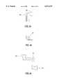
- FIG. 1is a perspective view of a top side of a backplane including six radiating elements
- FIG. 2is a top plan view of the top side of the backplane of FIG. 1;
- FIG. 3is a side elevation of the backplane of FIG. 1;
- FIG. 4ais a side view of two half dipoles
- FIG. 4bis a top view of two half dipoles
- FIG. 4cis a top view of two half dipoles laying flat prior to each half dipole being bent approximately 90 degrees, as illustrated in FIGS. 4a and 4b.
- FIG. 5is a perspective view of a radiating element illustrating the attached PCB balun
- FIG. 6is a perspective view of a radiating element illustrating the attached PCB balun and a generally Z-shaped connector
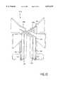
- FIG. 7is a perspective view of the near end of the backplane illustrated in FIG. 1, with the end cap removed, illustrating the radome;
- FIG. 8is a graph illustrating the coupling of the antenna of FIGS. 1-3;
- FIG. 9is a perspective view of a top side of a backplane including six radiating elements and a plate with apertures for accommodating the radiating elements;
- FIG. 10is a top plan view of the top side of the backplane of FIG. 9;
- FIG. 11is a side elevation of the backplane of FIG. 9;
- FIG. 12is a perspective view of a radiating element illustrating the attached PCB balun
- FIG. 13is a perspective view of a radiating element illustrating the attached PCB balun and a generally Z-shaped connector
- FIG. 14is a perspective view of the near end of the backplane illustrated in FIG. 9, with the end cap removed, illustrating the radome;
- FIG. 15is a graph illustrating the coupling of the antenna of FIGS. 9-11.
- the present inventionis useful in wireless communication systems.
- One embodiment of the present inventionoperates in the Personal Communication System (PCS)/Personal Communication Network (PCN) band of frequencies of 1850-1990 and 1710-1880 MHz, respectively.
- PCSPersonal Communication System
- PCNPersonal Communication Network
- wireless telephone userstransmit an electromagnetic signal to a base station comprising a plurality of antennas which receive the signal transmitted by the wireless telephone users.
- the present inventioncan also be used in all types of telecommunications systems.
- FIGS. 1-3are a 90 degree azimuthal, half power beam width (HPBW) antenna, i.e., the antenna achieves a 90 degree 3 dB beamwidth.
- FIGS. 1-3show an antenna array 10 of crossed, dual polarized dipole radiating elements 11a-f that are connected to a backplane 12 by screws.
- the backplane 12is a metal ground plane and has a first side 14 and a second side 16 (shown in FIG. 7).
- the composition and dimensions of the radiating elements 11a-f and the backplane 12contribute to the radiation characteristics, beam width and impedance of the antenna.
- the radiating elements 11a-f and the backplane 12are composed of a metal such as aluminum. However, other metals such as copper or brass can be used to construct the radiating elements and the backplane 12.
- the gain of the antennais proportional to the number of spaced radiating elements present in the array. In other words, increasing the number of radiating elements in the array increases the gain while decreasing the number of radiating elements decreases the antenna's gain. Therefore, although only six radiating elements are illustrated, the number of radiating elements can be increased to any number to increase the gain. Conversely, the number of radiating elements can be decreased to any number to decrease the gain.
- the radiating elements 11a-ftransmit and receive electromagnetic signals and are comprised of pairs of dipoles 18a and 18b, 20a and 20b, 22a and 22b, 24a and 24b, 26a and 26b and 28a and 28b, respectively.
- each dipole pairis crossed and configured with 45 degree slant angles (with respect to an axis 13 of the array 10). That is, the axes of the dipoles are arranged such that they are parallel with the polarization sense required. As shown, the slant angles + ⁇ and - ⁇ are +45 degrees and -45 degrees, respectively.
- angles +45 degrees and -45 degreescan be varied to optimize the performance of the antenna.
- angles + ⁇ and - ⁇need not be identical in magnitude.
- + ⁇ and - ⁇can be +30 degrees and -60 degrees, respectively.
- Each dipoleis comprised of a metal such as aluminum and has the shape illustrated in FIGS. 4a-c.
- FIG. 4ashows a side view of one half of the dipole 18a and one half of the dipole 18b.
- Each of said half dipoleshas a generally ax-like profile, as illustrated in FIG. 4a.
- Each half dipoleis physically part of the same piece of metal and is at earth ground at DC. However, each half dipole operates independently of the other at RF.
- FIG. 4bshows how each half dipole is attached to the other half dipole.
- Hole 82allows a fastener such as a screw to secure each half dipole pair to the backplane 12.
- FIG. 4cshows the half dipole pairs laying flat prior to each half dipole being bent up to approximately 90 degrees with respect to the backplane 12.
- Each of the radiating elements 11a-freceives signals having polarizations of +45 degrees and -45 degrees. That is, one dipole in the radiating element receives signals having polarizations of +45 degrees while the other dipole receives signals having polarizations of -45 degrees.
- the received signals from parallel dipoles, 18a, 20a, 22a, 24a, 26a, and 28a or 18b, 20b, 22b, 24b, 26b, and 28bare distributed to a receiver using a printed circuit board (PCB) feed network 30 (illustrated in FIG. 7) for each polarization.
- the PCB feed network 30is attached to the second side 16 of the backplane 12 by plastic rivets 32 that minimize the intermodulation distortion (IMD).
- the PCB feed network 30is located on the second side 16 in order to isolate the feed network 30 from the radiating elements 11a-f.
- the feed network 30distributes the received signals from the array of radiating elements 11a-f on the first side 14 of backplane 12 to a diversity receiver for further processing.
- Each of the radiating elements 11a-fcan also act as a transmitting antenna.
- a PCB balanced/unbalanced (balun) transformer 33is shown attached to radiating element 11a.
- the general operation of a balunis well known in the art and is described in an article by Brian Edward & Daniel Rees, A Broadband Printed Dipole with Integrated Balun, MICROWAVE JOURNAL, May 1987, at 339-344, which is incorporated herein by reference.
- One PCB balun 33is bonded to each dipole 18a, 18b, 20a, 20b, 22a, 22b, 24a, 24b, 26a, 26b, 28a and 28b. Attaching the PCB balun 33 to the metal dipoles provides mechanical integrity to the PCB balun 33.
- the PCB baluns 33match the unbalanced transmission lines of the feed network 30 with the balanced pairs of dipole elements 18a and 18b, 20a and 20b, 22a and 22b, 24a and 24b, 26a and 26b and 28a and 28b, respectively.
- Each PCB balun 33is shaped like an inverted U. However, as seen in FIG. 6, in order to achieve a symmetrical pair of crossed dipoles, one leg of the inverted U is substantially longer than the other leg.
- Each balun 33includes a PCB 73 and a wire lead 75 for matching the unbalanced feed network 30 with each balanced pair of dipoles.
- a PCB balunavoids the need for small metal and plastic parts in constructing the balun.
- the PCB balun 33is connected to the PCB feed network 30 by a generally Z-shaped connector 80, partially illustrated in FIG. 6.
- the Z-shaped connector 80comprises two parallel sections spaced by a slanted section. This configuration allows for tolerance buildup between the dipole element, the backplane and the PCB feed network 30.
- a parasitic element 34is positioned transverse to the vertical axis 13 approximately midway along the length of the backplane 12.
- the parasitic element 34is formed of metal.
- This metalis preferably aluminum, although other metals such as copper or brass can also be used.
- a primary electromagnetic wave or field incident upon the array structureinduces currents on the surfaces of the crossed dipoles of each of the radiating elements 11a-f, the parasitic element 34, and the surrounding metal structure. These induced currents create a weaker secondary electromagnetic field which will combine with the primary electromagnetic field. A state of equilibrium will occur such that the final electromagnetic field is different from the primary electromagnetic field.
- the dimensions and position of the parasitic element 34are factors in determining the final field.
- the improved isolation of the present inventionis achieved by currents induced on the parasitic element 34 which re-radiate energy that cancels the energy which couples from one polarization to the other thereby causing an increase in isolation.
- primary electromagnetic fieldsinduce currents in the metallic parasitic element 34, these induced currents re-radiate secondary electromagnetic fields that cancel with portions of the primary electromagnetic fields, thereby improving isolation.
- the parasitic element 34is shaped like a bow tie and is positioned transverse to the vertical axis 13 approximately midway along the length of the backplane 12.
- the parasitic element 34is mounted on a dielectric standoff 35 which is fastened to the backplane 12 by a vertical screw disposed within the standoff 35.
- the parasitic element 34is positioned in a plane generally horizontal to the backplane 12 at a height approximately equal to the height of the midpoint of the vertical bow tie shaped crossed dipoles 18a and 18b, 20a and 20b, 22a and 22b, 24a and 24b, 26a and 26b and 28a and 28b. This height has been found to optimize isolation for this array configuration. However, the height of the parasitic element 34 can vary depending on the array configuration.
- a network analyzeris used to determine the optimum positioning of the element.
- the network analyzermeasures the isolation of any given configuration of radiating elements 11a-f and the parasitic element 34.
- the dielectric standoff 35is disposed in a slot 70 that allows the dielectric standoff 35 to be adjusted with respect to the axis 13. This allows for the optimal axial displacement of the parasitic element 34.
- the dimensions of the parasitic element 34control the magnitude of the current produced. Thus, the performance of the system can also be optimized by changing the dimensions of the parasitic element 34.
- the parasitic element 34is situated to prevent undue side effects such as degrading the return loss voltage standing wave ratio (VSWR) and disturbing the normal array radiation patterns. It has been found that optimum antenna performance occurs when the parasitic element 34 is placed parallel to or perpendicular to the vertical axis 13 of the array 10. Tests performed on a pattern test range and/or network analyzer are used to determine the optimum antenna performance for any given antenna array configuration.
- VSWRreturn loss voltage standing wave ratio
- a pair of sidewalls 36contribute to the 90 degree azimuthal radiation pattern of the antenna 10.
- the sidewalls 36are fastened to the backplane 12 along the length of the backplane 12 by screws 38 illustrated in FIG. 7.
- the sidewalls 36are substantially C-shaped in cross-section and extend partially around the backplane 12.
- the sidewalls 36have a portion 63 that extends partially under the backplane 12, as illustrated in FIG. 7.
- the sidewalls 36are composed of a metal such as aluminum.
- other metalssuch as copper or brass can be used to construct the sidewalls 36.
- the edges 40 of the sidewalls 36create a diffraction pattern that increases the beamwidth approximately 10 degrees compared to similar antennas with no sidewalls.
- the edges 40diffract part of the signal, thereby spreading the signal out.
- the 3 dB beamwidth of the transmitted or received signalis increased.
- the metal backplane 12 of the antenna 10is greater in width than other backplanes using alternative feed networks.
- the increased metal of the backplane 12 and the sidewalls 36help to increase the front to back ratio, thereby improving the performance of the antenna 10.
- the composition and dimensions of the sidewalls 36thus contribute to the radiation characteristics, beam width and the impedance of the antenna.
- the gain of the antenna 10is maximized due to the use of dipole radiating elements 11a-f which are an efficient radiator and by using an efficient (0.062" thick) PCB feed network 30.
- FIG. 7also illustrates a radome 60 that encloses the antenna array 10.
- the radome 60is secured to the antenna 10 by guide rails 62 integrally formed with the radome 60.
- Guide rails 62mate with the portion 63 of the sidewalls 36 that extends under the backplane 12.
- End caps 64 and 66best illustrated in FIG. 1, snap onto the radome to seal in the antenna 10 and protect the antenna from adverse environmental conditions.
- the end cap 66has two DIN connectors 67 that allow coaxial cables to electrically connect each dipole of the antenna 10 with an external device such as a receiver or transmitter.
- Gaskets 68illustrated in FIG. 7, seal the fasteners that connect the antenna 10 to a base station. This further protects the antenna 10 from water and other environmental elements.
- FIGS. 1-3six crossed dipole radiating elements were placed on a backplane 830.10 mm long by 172.67 mm wide to operate in the PCS/PCN band of frequencies which is 1710-1990 MHz.
- the vertical axis 13 of the array 10stretched along the 830.10 mm length.
- the six dual polarized, crossed dipole radiating elements 11a-fwere aligned along the vertical axis 13 of the array 10, each element having slant angles of +45 degrees and -45 degrees with respect to the vertical axis 13.
- the PCB used for the PCB feed network 30is approximately 0.062" thick and the PCB used for the PCB balun 33 is approximately 0.032" thick, both of the PCB's having a dielectric constant of 3.0.
- the illustrated antenna configurationachieved the isolation curve illustrated in FIG. 8.
- the graph of FIG. 8actually represents coupling. However, coupling is the opposite of isolation, i.e., coupling of 33 dB is equivalent to 33 dB isolation.
- FIGS. 9-11is a 65 degree azimuthal HPBW antenna, i.e., the antenna achieves a 65 degree 3 dB beamwidth.
- FIGS. 9-11show an antenna array 210 of crossed, dual dipole radiating elements 211a-f that are attached to a backplane 212.
- the antenna 210operates in the PCS/PCN band of frequencies of 1850-1990 and 1710-1880 MHz, respectively.
- the composition and dimensions of the backplane 212 and the radiating elements 211a-fcontribute to the radiation characteristics, beam width and the impedance of the antenna. Because much of the antenna 210 is identical to the antenna 10 described above, the description below focuses on those portions of the antenna 210 that are different from the antenna 10.
- the radiating elements 211a-ftransmit and receive electromagnetic signals and are comprised of pairs of dipoles, 218a and 218b, 220a and 220b, 222a and 222b, 224a and 224b, 226a and 226b and 228a and 228b, respectively.
- the dipoles comprising the radiating elements 211a-fare crossed and configured with 45 degree slant angles (with respect to an axis 213 of the array 210).
- Each of the radiating elements 211a-freceives signals having polarizations of +45 degrees and -45 degrees.
- the received signals from parallel dipoles, 218a, 220a, 222a, 224a, 226a, and 228a or 218b, 220b, 222b, 224b, 226b, and 228bare distributed to a receiver using a printed circuit board (PCB) feed network 230 (illustrated in FIG. 14) for each polarization.
- the PCB feed network 230is attached to a bottom side 216 of the backplane 212 by plastic rivets 232 in order to minimize the intermodulation distortion (IMD).
- IMDintermodulation distortion
- the feed network 230distributes the received signals from the array of radiating elements 211a-f on the top side 214 of backplane 212 to a diversity receiver which chooses the stronger of the two signals for further processing.
- Each of the radiating elements 211a-fcan also act as a transmitting antenna.
- a PCB balun transformer 233is shown attached to radiating element 211a.
- One PCB balun 233is bonded to each dipole 218a, 218b, 220a, 220b, 222a, 222b, 224a, 224b, 226a, 226b, 228a and 228b. Attaching the PCB balun 33 to the metal dipoles provides mechanical integrity to the PCB balun 33.
- the PCB baluns 233match the unbalanced transmission lines of the feed network 230 with the balanced dipole elements 218a and 218b, 220a and 220b, 222a and 222b, 224a and 224b, 226a and 226b and 228a and 228b, respectively.
- Each PCB balun 233is shaped like an inverted U. However, as seen in FIG. 13, in order to achieve a symmetrical pair of crossed dipoles, one leg of the inverted U is substantially longer than the other leg.
- Each balun 233includes a PCB 273 and a wire lead 275 for matching the unbalanced feed network 230 with each pair of balanced dipoles.
- a PCB balunalleviates the necessity to use small metal and plastic parts in constructing the balun.
- the PCB balun 233is connected to the PCB feed network 230 by a generally Z-shaped connector 280, illustrated in FIG. 13.
- the Z-shaped connector 280comprises two parallel sections spaced by a slanted section. This configuration allows for tolerance buildup between the dipole element, the backplane and the PCB feed network 230.
- a plate 244 having square apertures 246is supported and elevated from the backplane 212 by dielectric standoffs 248, best illustrated in FIG. 11.
- Metal screws 250 and a non-conducting screw 252secure the plate 244 and the dielectric standoffs 248 to the backplane 212.
- the metal screws 250secure the plate 244 and four dielectric standoffs 248 to the corners of the backplane 212.
- the non-conducting screw 252secures the middle portion of plate 244 and one dielectric standoff 248 to the backplane 212.
- the symmetry of the plate 244helps improve the port-to-port isolation and the cross polarization of the antenna 210.
- a pair of sidewalls 242contribute to the 65 degree azimuthal radiation pattern of the antenna 210.
- the sidewalls 242are fastened to the backplane 212 along the length of the backplane 212 by screws 238 illustrated in FIG. 14.
- the sidewalls 242are substantially L-shaped in cross-section and have a portion 263 that extends partially under the backplane 212.
- the sidewalls 242narrow the 3 dB beamwidth of the antenna 210 compared to similar antennas with no sidewalls.
- the gain of the antenna 210is maximized due to the use of dipole radiating elements 211a-f which are an efficient radiator and by using an efficient (0.062" thick) PCB feed network 230.
- a radome 260likewise encloses the antenna array 210, as illustrated in FIG. 14.
- the radome 260is secured to the antenna 210 by guide rails 262 integrally formed with the radome 260.
- Guide rails 262mate with a portion 263 of sidewalls 242 that extends under the backplane 212.
- End caps 264 and 266, best illustrated in FIG. 9,snap onto the radome to seal in the antenna 210 and protect the antenna from adverse environmental conditions.
- End cap 266has two DIN connectors that allow coaxial cables to electrically connect each dipole of the antenna 210 with an external device such as a receiver or transmitter.
- Gaskets 268seal the fasteners that connect the antenna 210 to a base station. This further protects the antenna 210 from water and other environmental elements.
- FIGS. 9-11six crossed dipole radiating elements were placed on a backplane 830.10 mm long by 172.67 mm wide to operate in the PCS/PCN band of frequencies which is 1710-1990 MHz.
- the vertical axis 213 of the array 210stretched along the 830.10 mm length.
- the six dual polarized, crossed dipole radiating elements 211a-fwere aligned along the vertical axis 213 of the array 210, each element having slant angles of +45 degrees and -45 degrees with respect to the vertical axis 213.
- the PCB used for the PCB feed network 230is approximately 0.062" thick and the PCB used for the PCB balun 233 is approximately 0.032" thick, both of the PCB's having a dielectric constant of 3.0.
- the illustrated antenna configurationachieved the isolation curve illustrated in FIG. 15.
- the graph of FIG. 15actually represents coupling. However, coupling is the opposite of isolation, i.e., coupling of -34 dB is equivalent to 34 dB isolation.
- the antenna of the present inventionincludes dual polarized radiating elements that produce two orthogonally polarized signals.
- the present inventionfurther provides an antenna array comprised of crossed dipoles.
- the present antenna arrayimproves the isolation between the electromagnetic fields produced by the crossed dipoles.
- the present antenna arrayalso minimizes the number of antennas required in a wireless telecommunication system, thereby providing an aesthetically pleasing base station that is of minimum size.
- the present antenna arrayprovides approximately 30 dB port-to-port isolation.
- the present inventionalso provides a less expensive antenna array capable of high gain.
Landscapes
- Engineering & Computer Science (AREA)
- Computer Networks & Wireless Communication (AREA)
- Variable-Direction Aerials And Aerial Arrays (AREA)
- Support Of Aerials (AREA)
- Details Of Aerials (AREA)
Abstract
Description
Claims (63)
Priority Applications (5)
| Application Number | Priority Date | Filing Date | Title |
|---|---|---|---|
| US09/007,648US6072439A (en) | 1998-01-15 | 1998-01-15 | Base station antenna for dual polarization |
| GB9900664AGB2333400B (en) | 1998-01-15 | 1999-01-14 | Base station antenna for dual polarization |
| DE19901179ADE19901179A1 (en) | 1998-01-15 | 1999-01-14 | Dual polarization base station antenna for wireless telecommunication systems |
| BR9900064-4ABR9900064A (en) | 1998-01-15 | 1999-01-14 | Base station antenna for dual polarization. |
| CNB991010914ACN1154201C (en) | 1998-01-15 | 1999-01-15 | Dual Polarized Base Station Antennas |
Applications Claiming Priority (1)
| Application Number | Priority Date | Filing Date | Title |
|---|---|---|---|
| US09/007,648US6072439A (en) | 1998-01-15 | 1998-01-15 | Base station antenna for dual polarization |
Publications (1)
| Publication Number | Publication Date |
|---|---|
| US6072439Atrue US6072439A (en) | 2000-06-06 |
Family
ID=21727391
Family Applications (1)
| Application Number | Title | Priority Date | Filing Date |
|---|---|---|---|
| US09/007,648Expired - Fee RelatedUS6072439A (en) | 1998-01-15 | 1998-01-15 | Base station antenna for dual polarization |
Country Status (5)
| Country | Link |
|---|---|
| US (1) | US6072439A (en) |
| CN (1) | CN1154201C (en) |
| BR (1) | BR9900064A (en) |
| DE (1) | DE19901179A1 (en) |
| GB (1) | GB2333400B (en) |
Cited By (94)
| Publication number | Priority date | Publication date | Assignee | Title |
|---|---|---|---|---|
| US6339405B1 (en)* | 2001-05-23 | 2002-01-15 | Sierra Wireless, Inc. | Dual band dipole antenna structure |
| US20020158808A1 (en)* | 2000-03-10 | 2002-10-31 | Jinichi Inoue | Cross dipole antenna and composite antenna |
| US6529172B2 (en) | 2000-08-11 | 2003-03-04 | Andrew Corporation | Dual-polarized radiating element with high isolation between polarization channels |
| US6567056B1 (en)* | 2001-11-13 | 2003-05-20 | Intel Corporation | High isolation low loss printed balun feed for a cross dipole structure |
| US6597324B2 (en)* | 2001-05-03 | 2003-07-22 | Radiovector U.S.A. Llc | Single piece element for a dual polarized antenna |
| US6621465B2 (en)* | 2001-03-20 | 2003-09-16 | Allen Telecom Group, Inc. | Antenna array having sliding dielectric phase shifters |
| FR2840455A1 (en)* | 2002-06-04 | 2003-12-05 | Jacquelot Technologies | WIDE RADIATION ELEMENT WITH DOUBLE POLARIZATION, OF GENERAL SQUARE FORM |
| US6697029B2 (en)* | 2001-03-20 | 2004-02-24 | Andrew Corporation | Antenna array having air dielectric stripline feed system |
| US6717555B2 (en)* | 2001-03-20 | 2004-04-06 | Andrew Corporation | Antenna array |
| US6747606B2 (en) | 2002-05-31 | 2004-06-08 | Radio Frequency Systems Inc. | Single or dual polarized molded dipole antenna having integrated feed structure |
| US20040183739A1 (en)* | 2003-03-17 | 2004-09-23 | Bisiules Peter John | Folded dipole antenna, coaxial to microstrip transition, and retaining element |
| US20040201541A1 (en)* | 2001-09-07 | 2004-10-14 | Izzat Narian K. | Wide bandwidth base station antenna and antenna array |
| US20040201543A1 (en)* | 2003-04-11 | 2004-10-14 | Kathrein-Werke Kg. | Reflector, in particular for a mobile radio antenna |
| US20040201542A1 (en)* | 2003-04-11 | 2004-10-14 | Kathrein-Werke Kg | Reflector, in particular for a mobile radio antenna |
| US20040252071A1 (en)* | 2002-03-26 | 2004-12-16 | Bisiules Peter John | Multiband dual polarized adjustable beamtilt base station antenna |
| US20050001778A1 (en)* | 2003-07-03 | 2005-01-06 | Kevin Le | Wideband dual polarized base station antenna offering optimized horizontal beam radiation patterns and variable vertical beam tilt |
| US20050078046A1 (en)* | 2003-10-10 | 2005-04-14 | Theobold David M. | Antenna array with vane-supported elements |
| US20050179610A1 (en)* | 2002-12-13 | 2005-08-18 | Kevin Le | Directed dipole antenna |
| EP1566857A1 (en)* | 2004-02-20 | 2005-08-24 | Alcatel | Dual polarized antenna module |
| US20050206575A1 (en)* | 2000-12-21 | 2005-09-22 | Chadwick Peter E | Dual polarisation antenna |
| US20050231437A1 (en)* | 2004-04-16 | 2005-10-20 | Hon Hai Precision Ind. Co., Ltd. | Dipole antenna |
| US20050253769A1 (en)* | 2004-05-12 | 2005-11-17 | Timofeev Igor E | Crossed dipole antenna element |
| US20060205341A1 (en)* | 2005-03-11 | 2006-09-14 | Ems Technologies, Inc. | Dual polarization wireless repeater including antenna elements with balanced and quasi-balanced feeds |
| US20060220976A1 (en)* | 2005-04-05 | 2006-10-05 | Spx Corporation | Vertically polarized panel antenna system and method |
| EP1751821A1 (en)* | 2004-06-04 | 2007-02-14 | Andrew Corporation | Directive dipole antenna |
| US20070176838A1 (en)* | 2004-03-03 | 2007-08-02 | Katherine Zink | Broadband structurally-embedded conformal antenna |
| US20070200783A1 (en)* | 2004-04-15 | 2007-08-30 | Cellmax Technologies Ab | Dipole design |
| US20070229385A1 (en)* | 2006-03-30 | 2007-10-04 | Gang Yi Deng | Broadband dual polarized base station antenna |
| USRE40434E1 (en) | 1997-05-14 | 2008-07-15 | Andrew Corporation | High isolation dual polarized antenna system using dipole radiating elements |
| US20090204372A1 (en)* | 2007-11-27 | 2009-08-13 | Johnston Ronald H | Dual circularly polarized antenna |
| US20090213013A1 (en)* | 2008-02-25 | 2009-08-27 | Bjorn Lindmark | Antenna feeding arrangement |
| US20090284430A1 (en)* | 2008-05-16 | 2009-11-19 | Asustek Computer Inc. | Antenna array |
| US20090305710A1 (en)* | 2008-05-02 | 2009-12-10 | Spx Corporation | Super Economical Broadcast System and Method |
| US20100134374A1 (en)* | 2008-04-25 | 2010-06-03 | Spx Corporation | Phased-Array Antenna Panel for a Super Economical Broadcast System |
| US20100141532A1 (en)* | 2008-02-25 | 2010-06-10 | Jesper Uddin | Antenna feeding arrangement |
| US7746284B2 (en)* | 2007-09-10 | 2010-06-29 | Electronics And Telecommunications Research Institute | Cross dipole, cross dipole module, array antenna, and multiple input multiple output antenna |
| CN101080848B (en)* | 2004-06-04 | 2012-09-12 | 安德鲁公司 | Directional Dipole Antenna |
| US20120280882A1 (en)* | 2009-08-31 | 2012-11-08 | Martin Zimmerman | Modular type cellular antenna assembly |
| US20130038504A1 (en)* | 2011-08-08 | 2013-02-14 | Stanley W. Livingston | Continuous current rod antenna |
| US20130222199A1 (en)* | 2012-02-09 | 2013-08-29 | AMI Research & Development, LLC | Stacked bow tie array with reflector |
| CN103682597A (en)* | 2013-12-13 | 2014-03-26 | 武汉虹信通信技术有限责任公司 | Broadband base station antenna radiating element and array antenna |
| US20150065151A1 (en)* | 1999-10-26 | 2015-03-05 | Fractus, S.A. | Interlaced multiband antenna arrays |
| US20150077303A1 (en)* | 2013-09-13 | 2015-03-19 | Sercomm Corporation | Antenna structure and electronic device using the same |
| US20150077294A1 (en)* | 2013-09-13 | 2015-03-19 | Sercomm Corporation | Antenna structure and electronic device using the same |
| US9070971B2 (en) | 2010-05-13 | 2015-06-30 | Ronald H. Johnston | Dual circularly polarized antenna |
| US20150222025A1 (en)* | 2014-01-31 | 2015-08-06 | Quintel Technology Limited | Antenna system with beamwidth control |
| US9123992B2 (en) | 2012-10-31 | 2015-09-01 | Electronics And Telecommunications Research Institute | Micro-miniature base station antenna having dipole antenna |
| US9184510B2 (en) | 2010-01-13 | 2015-11-10 | Continental Automotive Gmbh | Antenna structure for a vehicle |
| WO2016078475A1 (en) | 2014-11-18 | 2016-05-26 | 李梓萌 | Miniaturized dipole base station antenna |
| CN105703062A (en)* | 2016-04-12 | 2016-06-22 | 中国电子科技集团公司第五十四研究所 | Wideband, high-gain and dual-polarized array antenna for 5G base station and radiation unit of array antenna |
| US9397404B1 (en) | 2014-05-02 | 2016-07-19 | First Rf Corporation | Crossed-dipole antenna array structure |
| WO2016130246A1 (en) | 2015-02-13 | 2016-08-18 | Commscope Technologies Llc | Base station antenna with dummy elements between subarrays |
| CN106025523A (en)* | 2016-08-09 | 2016-10-12 | 武汉虹信通信技术有限责任公司 | Radiating element of cross structure and antenna array thereof |
| US20170040679A1 (en)* | 2014-01-23 | 2017-02-09 | Kathrein-Werke Kg | Mobile radio antenna |
| US9799962B2 (en) | 2014-01-28 | 2017-10-24 | Electronics And Telecommunications Research Institute | Dual-polarized dipole antenna |
| US9843108B2 (en) | 2014-07-25 | 2017-12-12 | Futurewei Technologies, Inc. | Dual-feed dual-polarized antenna element and method for manufacturing same |
| EP3280006A1 (en) | 2016-08-03 | 2018-02-07 | Li, Zimeng | A dual polarized antenna |
| US9905938B2 (en) | 2015-01-29 | 2018-02-27 | City University Of Hong Kong | Dual polarized high gain and wideband complementary antenna |
| US20180159237A1 (en)* | 2016-12-07 | 2018-06-07 | Raytheon Company | High-Powered Wideband Tapered Slot Antenna Systems and Methods |
| US20180191083A1 (en)* | 2015-08-31 | 2018-07-05 | Huawei Technologies Co, Ltd. | Antenna element used for multi-band antenna dual polarization |
| DE102017101977A1 (en) | 2017-02-01 | 2018-08-02 | Kathrein-Werke Kg | Radom with locking system and mobile phone antenna having such a radome |
| WO2018184354A1 (en)* | 2017-04-07 | 2018-10-11 | 深圳市景程信息科技有限公司 | High-isolation dual-polarization broadband antenna |
| CN109509970A (en)* | 2018-12-19 | 2019-03-22 | 广州司南天线设计研究所有限公司 | Dual polarized antenna |
| US10389018B2 (en)* | 2015-06-30 | 2019-08-20 | Huawei Technologies Co., Ltd. | Radiation apparatus |
| US20190334255A1 (en)* | 2018-04-25 | 2019-10-31 | Bae Systems Information And Electronic Systems Integration Inc. | Modular/scalable antenna array design |
| CN111129677A (en)* | 2018-10-31 | 2020-05-08 | 康普技术有限责任公司 | Isolator for antenna system and related antenna system |
| EP3671952A4 (en)* | 2017-09-19 | 2020-08-26 | Huawei Technologies Co., Ltd. | FOOD NETWORK OF A BASE STATION ANTENNA, BASE STATION ANTENNA AND BASE STATION |
| US11217905B2 (en) | 2017-06-09 | 2022-01-04 | Telefonaktiebolaget Lm Ericsson (Publ) | Dual-polarized crossed dipole and antenna arrangement having two such dual-polarized crossed dipoles |
| US20220094065A1 (en)* | 2020-09-21 | 2022-03-24 | Ace Technologies Corporation | Low loss wideband radiator for base station antenna |
| US20220158332A1 (en)* | 2019-07-31 | 2022-05-19 | Huawei Technologies Co., Ltd. | Communication base station |
| US20220181768A1 (en)* | 2020-02-24 | 2022-06-09 | Commscope Technologies Llc | Connectivity and field replaceability of radios mounted on base station antennas |
| WO2022188946A1 (en) | 2021-03-08 | 2022-09-15 | Telefonaktiebolaget Lm Ericsson (Publ) | A dipole radiator, a dual-polarized cross dipole comprising two dipole radiators and a mobile communication antenna comprising a plurality of dual-polarized cross dipoles |
| US11476585B1 (en)* | 2022-03-31 | 2022-10-18 | Isco International, Llc | Polarization shifting devices and systems for interference mitigation |
| US11502404B1 (en) | 2022-03-31 | 2022-11-15 | Isco International, Llc | Method and system for detecting interference and controlling polarization shifting to mitigate the interference |
| US11509072B1 (en) | 2022-05-26 | 2022-11-22 | Isco International, Llc | Radio frequency (RF) polarization rotation devices and systems for interference mitigation |
| US11509071B1 (en) | 2022-05-26 | 2022-11-22 | Isco International, Llc | Multi-band polarization rotation for interference mitigation |
| US11515652B1 (en) | 2022-05-26 | 2022-11-29 | Isco International, Llc | Dual shifter devices and systems for polarization rotation to mitigate interference |
| US11646493B2 (en)* | 2017-09-20 | 2023-05-09 | Nokia Shanghai Bell Co., Ltd. | Wireless telecommunication network antenna |
| US11670847B1 (en) | 2022-03-31 | 2023-06-06 | Isco International, Llc | Method and system for driving polarization shifting to mitigate interference |
| WO2023117096A1 (en) | 2021-12-22 | 2023-06-29 | Telefonaktiebolaget Lm Ericsson (Publ) | Antenna with dual polarized radiators |
| WO2023117097A1 (en) | 2021-12-22 | 2023-06-29 | Telefonaktiebolaget Lm Ericsson (Publ) | Antenna and cell site |
| US11705940B2 (en) | 2020-08-28 | 2023-07-18 | Isco International, Llc | Method and system for polarization adjusting of orthogonally-polarized element pairs |
| JP2023101788A (en)* | 2019-02-01 | 2023-07-21 | ケーエムダブリュ・インコーポレーテッド | wireless communication device |
| US11817631B2 (en) | 2019-03-22 | 2023-11-14 | Telefonaktiebolaget Lm Ericsson (Publ) | Antenna arrangement for mobile radio systems with at least one dual-polarised turnstile antenna |
| US11949489B1 (en) | 2022-10-17 | 2024-04-02 | Isco International, Llc | Method and system for improving multiple-input-multiple-output (MIMO) beam isolation via alternating polarization |
| US11956058B1 (en) | 2022-10-17 | 2024-04-09 | Isco International, Llc | Method and system for mobile device signal to interference plus noise ratio (SINR) improvement via polarization adjusting/optimization |
| US11985692B2 (en) | 2022-10-17 | 2024-05-14 | Isco International, Llc | Method and system for antenna integrated radio (AIR) downlink and uplink beam polarization adaptation |
| US11990976B2 (en) | 2022-10-17 | 2024-05-21 | Isco International, Llc | Method and system for polarization adaptation to reduce propagation loss for a multiple-input-multiple-output (MIMO) antenna |
| WO2024104558A1 (en) | 2022-11-14 | 2024-05-23 | Telefonaktiebolaget Lm Ericsson (Publ) | A feeding structure for a dual polarized radiator |
| US12219522B1 (en) | 2023-12-29 | 2025-02-04 | Isco International, Llc | Methods and systems for estimating the shape of an object generating passive intermodulation (PIM) interference |
| US12301315B1 (en) | 2023-12-29 | 2025-05-13 | Isco International, Llc | Methods and systems for detecting, measuring, and/or locating passive intermodulation sources via downlink (DL) signal injection |
| US12301298B1 (en) | 2023-12-29 | 2025-05-13 | Isco International, Llc | Methods and systems for locating interference sources via angle of arrival (AoA) |
| US12348285B1 (en) | 2023-12-29 | 2025-07-01 | Isco International, Llc | Methods and systems for detecting, measuring, and/or locating passive intermodulation (PIM) sources via beamforming |
| US12444855B2 (en) | 2023-12-01 | 2025-10-14 | Isco International, Llc | Polarization shifting devices and systems for interference mitigation |
Families Citing this family (17)
| Publication number | Priority date | Publication date | Assignee | Title |
|---|---|---|---|---|
| DE10064129B4 (en)* | 2000-12-21 | 2006-04-20 | Kathrein-Werke Kg | Antenna, in particular mobile radio antenna |
| GB2424765B (en)* | 2005-03-29 | 2007-07-25 | Csa Ltd | A dipole antenna |
| CN1688067B (en)* | 2005-04-27 | 2011-06-15 | 摩比天线技术(深圳)有限公司 | Bipolarized loaded antenna radiating unit |
| FI120522B (en) | 2006-03-02 | 2009-11-13 | Filtronic Comtek Oy | A new antenna structure and a method for its manufacture |
| CN201001113Y (en)* | 2006-12-21 | 2008-01-02 | 华为技术有限公司 | A connector and a radio frequency device integrated with the connector |
| CN101197470B (en)* | 2007-12-12 | 2011-08-24 | 西安海天天线科技股份有限公司 | Broadband dual-polarization antenna feeder unit |
| FR2943465A1 (en)* | 2009-03-17 | 2010-09-24 | Groupe Ecoles Telecomm | ANTENNA WITH DOUBLE FINS |
| CN102157783A (en)* | 2011-03-17 | 2011-08-17 | 京信通信系统(中国)有限公司 | Dual-polarized broadband radiation unit and array antenna |
| KR20140146118A (en)* | 2012-03-19 | 2014-12-24 | 갈트로닉스 코포레이션 리미티드 | Multiple-input multiple-output antenna and broadband dipole radiating element therefore |
| CN102664662A (en)* | 2012-04-27 | 2012-09-12 | 深圳光启创新技术有限公司 | Wireless mobile interconnect device with multi-antenna system |
| CN102891353B (en)* | 2012-09-29 | 2015-08-19 | 武汉虹信通信技术有限责任公司 | A kind of umbrella shape ultra-wideband Bipolarization antenna for base station radiating element |
| CN202797284U (en) | 2012-10-10 | 2013-03-13 | 华为技术有限公司 | Feed network, antenna and dual-polarized antenna array feed circuit |
| PL404254A1 (en)* | 2013-06-07 | 2014-12-08 | Telekomunikacja Polska Spółka Akcyjna | Adaptive antenna and adaptive antenna beam control method |
| CN104466426A (en)* | 2014-11-11 | 2015-03-25 | 李梓萌 | Baffle-board used for base station antenna and base station antenna array structure |
| DE102015007504B4 (en) | 2015-06-11 | 2019-03-28 | Kathrein Se | Dipole radiator arrangement |
| TWI565138B (en)* | 2015-10-20 | 2017-01-01 | Crossed bipolar antenna structure | |
| EP4315505A1 (en) | 2021-03-30 | 2024-02-07 | Telefonaktiebolaget LM Ericsson (publ) | Mobile communication antenna |
Citations (81)
| Publication number | Priority date | Publication date | Assignee | Title |
|---|---|---|---|---|
| US2130033A (en)* | 1934-07-05 | 1938-09-13 | Telefunken Gmbh | Directive beam radiator |
| US2455403A (en)* | 1945-01-20 | 1948-12-07 | Rca Corp | Antenna |
| FR1236535A (en)* | 1959-06-08 | 1960-07-22 | Csf | New television antenna panel |
| US3482253A (en)* | 1967-09-19 | 1969-12-02 | Bruno Zucconi | Antenna housing |
| US3496570A (en)* | 1967-03-28 | 1970-02-17 | Radiation Inc | Van atta array |
| US3680143A (en)* | 1970-07-01 | 1972-07-25 | Hughes Aircraft Co | Shaped beam antenna |
| US3680139A (en)* | 1970-08-17 | 1972-07-25 | Westinghouse Electric Corp | Common antenna aperture having polarization diversity |
| US3681769A (en)* | 1970-07-30 | 1972-08-01 | Itt | Dual polarized printed circuit dipole antenna array |
| US3681771A (en)* | 1970-03-23 | 1972-08-01 | Macdowell Associates Inc | Retroflector dipole antenna array and method of making |
| US3701157A (en)* | 1971-06-03 | 1972-10-24 | Us Air Force | Helicopter uhf antenna system for satellite communications |
| US3718935A (en)* | 1971-02-03 | 1973-02-27 | Itt | Dual circularly polarized phased array antenna |
| US3720953A (en)* | 1972-02-02 | 1973-03-13 | Hughes Aircraft Co | Dual polarized slot elements in septated waveguide cavity |
| US3742506A (en)* | 1971-03-01 | 1973-06-26 | Communications Satellite Corp | Dual frequency dual polarized antenna feed with arbitrary alignment of transmit and receive polarization |
| US3747114A (en)* | 1972-02-18 | 1973-07-17 | Textron Inc | Planar dipole array mounted on dielectric substrate |
| US3750185A (en)* | 1972-01-18 | 1973-07-31 | Westinghouse Electric Corp | Dipole antenna array |
| US3810185A (en)* | 1972-05-26 | 1974-05-07 | Communications Satellite Corp | Dual polarized cylindrical reflector antenna system |
| US3821742A (en)* | 1973-01-05 | 1974-06-28 | F Pollard | Dual polarized antenna with triangular wire reflector |
| US3922680A (en)* | 1974-08-28 | 1975-11-25 | Us Army | Space feed receiver array |
| US4015263A (en)* | 1976-02-23 | 1977-03-29 | Textron, Inc. | Dual polarized blade antenna |
| US4031537A (en)* | 1974-10-23 | 1977-06-21 | Andrew Alford | Collinear dipole array with reflector |
| US4087818A (en)* | 1975-10-14 | 1978-05-02 | Communications Satellite Corporation | Lossless network and method for orthogonalizing dual polarized transmission systems |
| US4180817A (en)* | 1976-05-04 | 1979-12-25 | Ball Corporation | Serially connected microstrip antenna array |
| US4193077A (en)* | 1977-10-11 | 1980-03-11 | Avnet, Inc. | Directional antenna system with end loaded crossed dipoles |
| US4198641A (en)* | 1976-08-09 | 1980-04-15 | Rca Corporation | Rotating field polarization antenna system |
| US4223317A (en)* | 1977-12-27 | 1980-09-16 | Monogram Industries, Inc | Dual polarization antenna couplets |
| GB2048571A (en)* | 1979-05-03 | 1980-12-10 | Marconi Co Ltd | Circularly polarised antenna array |
| US4263598A (en)* | 1978-11-22 | 1981-04-21 | Motorola, Inc. | Dual polarized image antenna |
| US4340891A (en)* | 1978-04-26 | 1982-07-20 | Motorola, Inc. | Dual polarized base station receive antenna |
| US4364050A (en)* | 1981-02-09 | 1982-12-14 | Hazeltine Corporation | Microstrip antenna |
| US4412222A (en)* | 1980-07-19 | 1983-10-25 | Kabel- und Metallwerke Gutehoffnungshutte Aktiengesellschaft AG | Dual polarized feed with feed horn |
| US4464663A (en)* | 1981-11-19 | 1984-08-07 | Ball Corporation | Dual polarized, high efficiency microstrip antenna |
| US4472717A (en)* | 1982-03-19 | 1984-09-18 | The United States Of America As Represented By The Secretary Of The Army | Intrapulse polarization agile radar system (IPAR) |
| US4504836A (en)* | 1982-06-01 | 1985-03-12 | Seavey Engineering Associates, Inc. | Antenna feeding with selectively controlled polarization |
| US4513292A (en)* | 1982-09-30 | 1985-04-23 | Rca Corporation | Dipole radiating element |
| US4518969A (en)* | 1982-12-22 | 1985-05-21 | Leonard H. King | Vertically polarized omnidirectional antenna |
| US4571591A (en)* | 1983-12-16 | 1986-02-18 | The United States Of America As Represented By The Secretary Of The Navy | Three dimensional, orthogonal delay line bootlace lens antenna |
| US4644562A (en)* | 1985-08-28 | 1987-02-17 | At&T Company | Combined cross polarization interference cancellation and intersymbol interference equalization for terrestrial digital radio systems |
| US4647942A (en)* | 1981-11-20 | 1987-03-03 | Western Geophysical Co. | Circularly polarized antenna for satellite positioning systems |
| US4658262A (en)* | 1985-02-19 | 1987-04-14 | Duhamel Raymond H | Dual polarized sinuous antennas |
| US4675685A (en)* | 1984-04-17 | 1987-06-23 | Harris Corporation | Low VSWR, flush-mounted, adaptive array antenna |
| US4695844A (en)* | 1984-08-31 | 1987-09-22 | Societe D'electronique De La Region Pays De Loire | Device for receiving dual polarized microwave signals |
| US4710775A (en)* | 1985-09-30 | 1987-12-01 | The Boeing Company | Parasitically coupled, complementary slot-dipole antenna element |
| GB2191043A (en)* | 1986-05-28 | 1987-12-02 | Gen Electric Co Plc | Dipole array |
| US4737793A (en)* | 1983-10-28 | 1988-04-12 | Ball Corporation | Radio frequency antenna with controllably variable dual orthogonal polarization |
| US4772891A (en)* | 1987-11-10 | 1988-09-20 | The Boeing Company | Broadband dual polarized radiator for surface wave transmission line |
| US4821039A (en)* | 1985-05-01 | 1989-04-11 | Crane Patrick E | Dual polarized monopulse orthogonal superposition |
| US4825220A (en)* | 1986-11-26 | 1989-04-25 | General Electric Company | Microstrip fed printed dipole with an integral balun |
| US4839663A (en)* | 1986-11-21 | 1989-06-13 | Hughes Aircraft Company | Dual polarized slot-dipole radiating element |
| US4870426A (en)* | 1988-08-22 | 1989-09-26 | The Boeing Company | Dual band antenna element |
| US4929961A (en)* | 1989-04-24 | 1990-05-29 | Harada Kogyo Kabushiki Kaisha | Non-grounded type ultrahigh frequency antenna |
| US4943811A (en)* | 1987-11-23 | 1990-07-24 | Canadian Patents And Development Limited | Dual polarization electromagnetic power reception and conversion system |
| EP0416300A2 (en)* | 1989-09-08 | 1991-03-13 | Ball Corporation | Dual polarized spiral antenna |
| EP0433255A2 (en)* | 1989-12-14 | 1991-06-19 | COMSAT Corporation | Orthogonally polarized dual-band printed circuit antenna employing radiating elements capacitively coupled to feedlines |
| EP0464255A1 (en)* | 1990-07-03 | 1992-01-08 | Alcatel N.V. | Multiband antenna |
| EP0495507A1 (en)* | 1991-01-16 | 1992-07-22 | Alcatel N.V. | Retractable motorized multiband antenna |
| US5157409A (en)* | 1991-08-07 | 1992-10-20 | Radio Frequency Systems, Inc. | Cam lock antenna mounting assembly |
| US5172080A (en)* | 1991-06-28 | 1992-12-15 | Radio Frequency Systems, Inc. | Garnet centering ring for circulators and isolators |
| EP0523770A1 (en)* | 1991-07-15 | 1993-01-20 | Matsushita Electric Works, Ltd. | Low-noise-block downconverter for use with flat antenna receiving dual polarized electromagnetic waves |
| US5206655A (en)* | 1990-03-09 | 1993-04-27 | Alcatel Espace | High-yield active printed-circuit antenna system for frequency-hopping space radar |
| US5220330A (en)* | 1991-11-04 | 1993-06-15 | Hughes Aircraft Company | Broadband conformal inclined slotline antenna array |
| US5227807A (en)* | 1989-11-29 | 1993-07-13 | Ael Defense Corp. | Dual polarized ambidextrous multiple deformed aperture spiral antennas |
| EP0566522A1 (en)* | 1992-04-15 | 1993-10-20 | Celwave R.F. A/S | Antenna system and method of manufacturing said system |
| US5268701A (en)* | 1992-03-23 | 1993-12-07 | Raytheon Company | Radio frequency antenna |
| US5274391A (en)* | 1990-10-25 | 1993-12-28 | Radio Frequency Systems, Inc. | Broadband directional antenna having binary feed network with microstrip transmission line |
| US5309165A (en)* | 1992-05-09 | 1994-05-03 | Westinghouse Electric Corp. | Positioner with corner contacts for cross notch array and improved radiator elements |
| US5319379A (en)* | 1984-08-24 | 1994-06-07 | Hercules Defense Electronics Systems, Inc. | Parabolic dual reflector antenna with offset feed |
| US5321414A (en)* | 1990-03-01 | 1994-06-14 | Her Majesty In Right Of Canada As Represented By The Minister Of Communications | Dual polarization dipole array antenna |
| US5400042A (en)* | 1992-12-03 | 1995-03-21 | California Institute Of Technology | Dual frequency, dual polarized, multi-layered microstrip slot and dipole array antenna |
| EP0647977A1 (en)* | 1993-09-10 | 1995-04-12 | Radio Frequency Systems Inc. | Circularly polarized microcell antenna |
| EP0657956A1 (en)* | 1993-12-06 | 1995-06-14 | Alcatel N.V. | Antenna assembly |
| USH1460H (en)* | 1992-04-02 | 1995-07-04 | The United States Of America As Represented By The Secretary Of The Air Force | Spiral-mode or sinuous microscrip antenna with variable ground plane spacing |
| US5451969A (en)* | 1993-03-22 | 1995-09-19 | Raytheon Company | Dual polarized dual band antenna |
| US5453751A (en)* | 1991-04-24 | 1995-09-26 | Matsushita Electric Works, Ltd. | Wide-band, dual polarized planar antenna |
| US5499033A (en)* | 1993-07-02 | 1996-03-12 | Northern Telecom Limited | Polarization diversity antenna |
| EP0715477A2 (en)* | 1994-12-01 | 1996-06-05 | Radio Frequency Systems Inc. | Modular interconnect matrix for matrix connection of a plurality of antennas with a plurality of radio channels units |
| EP0725498A1 (en)* | 1995-01-31 | 1996-08-07 | Radio Frequency Systems Inc. | Radio signal scanning and targeting system for use in land mobile radio base sites |
| US5589843A (en)* | 1994-12-28 | 1996-12-31 | Radio Frequency Systems, Inc. | Antenna system with tapered aperture antenna and microstrip phase shifting feed network |
| US5630226A (en)* | 1991-07-15 | 1997-05-13 | Matsushita Electric Works, Ltd. | Low-noise downconverter for use with flat antenna receiving dual polarized electromagnetic waves |
| US5629713A (en)* | 1995-05-17 | 1997-05-13 | Allen Telecom Group, Inc. | Horizontally polarized antenna array having extended E-plane beam width and method for accomplishing beam width extension |
| US5818397A (en)* | 1993-09-10 | 1998-10-06 | Radio Frequency Systems, Inc. | Circularly polarized horizontal beamwidth antenna having binary feed network with microstrip transmission line |
| US5874924A (en)* | 1997-11-17 | 1999-02-23 | Lockheed Martin Corp. | Spacecraft antenna array with directivity enhancing rings |
Family Cites Families (2)
| Publication number | Priority date | Publication date | Assignee | Title |
|---|---|---|---|---|
| US5966102A (en)* | 1995-12-14 | 1999-10-12 | Ems Technologies, Inc. | Dual polarized array antenna with central polarization control |
| DE19722742C2 (en)* | 1997-05-30 | 2002-07-18 | Kathrein Werke Kg | Dual polarized antenna arrangement |
- 1998
- 1998-01-15USUS09/007,648patent/US6072439A/ennot_activeExpired - Fee Related
- 1999
- 1999-01-14DEDE19901179Apatent/DE19901179A1/ennot_activeWithdrawn
- 1999-01-14GBGB9900664Apatent/GB2333400B/ennot_activeExpired - Fee Related
- 1999-01-14BRBR9900064-4Apatent/BR9900064A/ennot_activeIP Right Cessation
- 1999-01-15CNCNB991010914Apatent/CN1154201C/ennot_activeExpired - Fee Related
Patent Citations (84)
| Publication number | Priority date | Publication date | Assignee | Title |
|---|---|---|---|---|
| US2130033A (en)* | 1934-07-05 | 1938-09-13 | Telefunken Gmbh | Directive beam radiator |
| US2455403A (en)* | 1945-01-20 | 1948-12-07 | Rca Corp | Antenna |
| FR1236535A (en)* | 1959-06-08 | 1960-07-22 | Csf | New television antenna panel |
| US3496570A (en)* | 1967-03-28 | 1970-02-17 | Radiation Inc | Van atta array |
| US3482253A (en)* | 1967-09-19 | 1969-12-02 | Bruno Zucconi | Antenna housing |
| US3681771A (en)* | 1970-03-23 | 1972-08-01 | Macdowell Associates Inc | Retroflector dipole antenna array and method of making |
| US3680143A (en)* | 1970-07-01 | 1972-07-25 | Hughes Aircraft Co | Shaped beam antenna |
| US3681769A (en)* | 1970-07-30 | 1972-08-01 | Itt | Dual polarized printed circuit dipole antenna array |
| US3680139A (en)* | 1970-08-17 | 1972-07-25 | Westinghouse Electric Corp | Common antenna aperture having polarization diversity |
| US3718935A (en)* | 1971-02-03 | 1973-02-27 | Itt | Dual circularly polarized phased array antenna |
| US3742506A (en)* | 1971-03-01 | 1973-06-26 | Communications Satellite Corp | Dual frequency dual polarized antenna feed with arbitrary alignment of transmit and receive polarization |
| US3701157A (en)* | 1971-06-03 | 1972-10-24 | Us Air Force | Helicopter uhf antenna system for satellite communications |
| US3750185A (en)* | 1972-01-18 | 1973-07-31 | Westinghouse Electric Corp | Dipole antenna array |
| US3720953A (en)* | 1972-02-02 | 1973-03-13 | Hughes Aircraft Co | Dual polarized slot elements in septated waveguide cavity |
| US3747114A (en)* | 1972-02-18 | 1973-07-17 | Textron Inc | Planar dipole array mounted on dielectric substrate |
| US3810185A (en)* | 1972-05-26 | 1974-05-07 | Communications Satellite Corp | Dual polarized cylindrical reflector antenna system |
| US3821742A (en)* | 1973-01-05 | 1974-06-28 | F Pollard | Dual polarized antenna with triangular wire reflector |
| US3922680A (en)* | 1974-08-28 | 1975-11-25 | Us Army | Space feed receiver array |
| US4031537A (en)* | 1974-10-23 | 1977-06-21 | Andrew Alford | Collinear dipole array with reflector |
| US4087818A (en)* | 1975-10-14 | 1978-05-02 | Communications Satellite Corporation | Lossless network and method for orthogonalizing dual polarized transmission systems |
| US4015263A (en)* | 1976-02-23 | 1977-03-29 | Textron, Inc. | Dual polarized blade antenna |
| US4180817A (en)* | 1976-05-04 | 1979-12-25 | Ball Corporation | Serially connected microstrip antenna array |
| US4198641A (en)* | 1976-08-09 | 1980-04-15 | Rca Corporation | Rotating field polarization antenna system |
| US4193077A (en)* | 1977-10-11 | 1980-03-11 | Avnet, Inc. | Directional antenna system with end loaded crossed dipoles |
| US4223317A (en)* | 1977-12-27 | 1980-09-16 | Monogram Industries, Inc | Dual polarization antenna couplets |
| US4340891A (en)* | 1978-04-26 | 1982-07-20 | Motorola, Inc. | Dual polarized base station receive antenna |
| US4263598A (en)* | 1978-11-22 | 1981-04-21 | Motorola, Inc. | Dual polarized image antenna |
| GB2048571A (en)* | 1979-05-03 | 1980-12-10 | Marconi Co Ltd | Circularly polarised antenna array |
| US4412222A (en)* | 1980-07-19 | 1983-10-25 | Kabel- und Metallwerke Gutehoffnungshutte Aktiengesellschaft AG | Dual polarized feed with feed horn |
| US4364050A (en)* | 1981-02-09 | 1982-12-14 | Hazeltine Corporation | Microstrip antenna |
| US4464663A (en)* | 1981-11-19 | 1984-08-07 | Ball Corporation | Dual polarized, high efficiency microstrip antenna |
| US4647942A (en)* | 1981-11-20 | 1987-03-03 | Western Geophysical Co. | Circularly polarized antenna for satellite positioning systems |
| US4472717A (en)* | 1982-03-19 | 1984-09-18 | The United States Of America As Represented By The Secretary Of The Army | Intrapulse polarization agile radar system (IPAR) |
| US4504836A (en)* | 1982-06-01 | 1985-03-12 | Seavey Engineering Associates, Inc. | Antenna feeding with selectively controlled polarization |
| US4513292A (en)* | 1982-09-30 | 1985-04-23 | Rca Corporation | Dipole radiating element |
| US4518969A (en)* | 1982-12-22 | 1985-05-21 | Leonard H. King | Vertically polarized omnidirectional antenna |
| US4737793A (en)* | 1983-10-28 | 1988-04-12 | Ball Corporation | Radio frequency antenna with controllably variable dual orthogonal polarization |
| US4571591A (en)* | 1983-12-16 | 1986-02-18 | The United States Of America As Represented By The Secretary Of The Navy | Three dimensional, orthogonal delay line bootlace lens antenna |
| US4675685A (en)* | 1984-04-17 | 1987-06-23 | Harris Corporation | Low VSWR, flush-mounted, adaptive array antenna |
| US5319379A (en)* | 1984-08-24 | 1994-06-07 | Hercules Defense Electronics Systems, Inc. | Parabolic dual reflector antenna with offset feed |
| US4695844A (en)* | 1984-08-31 | 1987-09-22 | Societe D'electronique De La Region Pays De Loire | Device for receiving dual polarized microwave signals |
| US4658262A (en)* | 1985-02-19 | 1987-04-14 | Duhamel Raymond H | Dual polarized sinuous antennas |
| US4821039A (en)* | 1985-05-01 | 1989-04-11 | Crane Patrick E | Dual polarized monopulse orthogonal superposition |
| US4644562A (en)* | 1985-08-28 | 1987-02-17 | At&T Company | Combined cross polarization interference cancellation and intersymbol interference equalization for terrestrial digital radio systems |
| US4710775A (en)* | 1985-09-30 | 1987-12-01 | The Boeing Company | Parasitically coupled, complementary slot-dipole antenna element |
| GB2191043A (en)* | 1986-05-28 | 1987-12-02 | Gen Electric Co Plc | Dipole array |
| US4839663A (en)* | 1986-11-21 | 1989-06-13 | Hughes Aircraft Company | Dual polarized slot-dipole radiating element |
| US4825220A (en)* | 1986-11-26 | 1989-04-25 | General Electric Company | Microstrip fed printed dipole with an integral balun |
| US4772891A (en)* | 1987-11-10 | 1988-09-20 | The Boeing Company | Broadband dual polarized radiator for surface wave transmission line |
| US4943811A (en)* | 1987-11-23 | 1990-07-24 | Canadian Patents And Development Limited | Dual polarization electromagnetic power reception and conversion system |
| US4870426A (en)* | 1988-08-22 | 1989-09-26 | The Boeing Company | Dual band antenna element |
| US4929961A (en)* | 1989-04-24 | 1990-05-29 | Harada Kogyo Kabushiki Kaisha | Non-grounded type ultrahigh frequency antenna |
| US5146234A (en)* | 1989-09-08 | 1992-09-08 | Ball Corporation | Dual polarized spiral antenna |
| EP0416300A2 (en)* | 1989-09-08 | 1991-03-13 | Ball Corporation | Dual polarized spiral antenna |
| US5227807A (en)* | 1989-11-29 | 1993-07-13 | Ael Defense Corp. | Dual polarized ambidextrous multiple deformed aperture spiral antennas |
| US5534877A (en)* | 1989-12-14 | 1996-07-09 | Comsat | Orthogonally polarized dual-band printed circuit antenna employing radiating elements capacitively coupled to feedlines |
| EP0433255A2 (en)* | 1989-12-14 | 1991-06-19 | COMSAT Corporation | Orthogonally polarized dual-band printed circuit antenna employing radiating elements capacitively coupled to feedlines |
| US5321414A (en)* | 1990-03-01 | 1994-06-14 | Her Majesty In Right Of Canada As Represented By The Minister Of Communications | Dual polarization dipole array antenna |
| US5206655A (en)* | 1990-03-09 | 1993-04-27 | Alcatel Espace | High-yield active printed-circuit antenna system for frequency-hopping space radar |
| EP0464255A1 (en)* | 1990-07-03 | 1992-01-08 | Alcatel N.V. | Multiband antenna |
| US5274391A (en)* | 1990-10-25 | 1993-12-28 | Radio Frequency Systems, Inc. | Broadband directional antenna having binary feed network with microstrip transmission line |
| EP0495507A1 (en)* | 1991-01-16 | 1992-07-22 | Alcatel N.V. | Retractable motorized multiband antenna |
| US5453751A (en)* | 1991-04-24 | 1995-09-26 | Matsushita Electric Works, Ltd. | Wide-band, dual polarized planar antenna |
| US5172080A (en)* | 1991-06-28 | 1992-12-15 | Radio Frequency Systems, Inc. | Garnet centering ring for circulators and isolators |
| US5630226A (en)* | 1991-07-15 | 1997-05-13 | Matsushita Electric Works, Ltd. | Low-noise downconverter for use with flat antenna receiving dual polarized electromagnetic waves |
| EP0523770A1 (en)* | 1991-07-15 | 1993-01-20 | Matsushita Electric Works, Ltd. | Low-noise-block downconverter for use with flat antenna receiving dual polarized electromagnetic waves |
| US5157409A (en)* | 1991-08-07 | 1992-10-20 | Radio Frequency Systems, Inc. | Cam lock antenna mounting assembly |
| US5220330A (en)* | 1991-11-04 | 1993-06-15 | Hughes Aircraft Company | Broadband conformal inclined slotline antenna array |
| US5268701A (en)* | 1992-03-23 | 1993-12-07 | Raytheon Company | Radio frequency antenna |
| USH1460H (en)* | 1992-04-02 | 1995-07-04 | The United States Of America As Represented By The Secretary Of The Air Force | Spiral-mode or sinuous microscrip antenna with variable ground plane spacing |
| EP0566522A1 (en)* | 1992-04-15 | 1993-10-20 | Celwave R.F. A/S | Antenna system and method of manufacturing said system |
| US5309165A (en)* | 1992-05-09 | 1994-05-03 | Westinghouse Electric Corp. | Positioner with corner contacts for cross notch array and improved radiator elements |
| US5400042A (en)* | 1992-12-03 | 1995-03-21 | California Institute Of Technology | Dual frequency, dual polarized, multi-layered microstrip slot and dipole array antenna |
| US5451969A (en)* | 1993-03-22 | 1995-09-19 | Raytheon Company | Dual polarized dual band antenna |
| US5499033A (en)* | 1993-07-02 | 1996-03-12 | Northern Telecom Limited | Polarization diversity antenna |
| EP0647977A1 (en)* | 1993-09-10 | 1995-04-12 | Radio Frequency Systems Inc. | Circularly polarized microcell antenna |
| US5481272A (en)* | 1993-09-10 | 1996-01-02 | Radio Frequency Systems, Inc. | Circularly polarized microcell antenna |
| US5818397A (en)* | 1993-09-10 | 1998-10-06 | Radio Frequency Systems, Inc. | Circularly polarized horizontal beamwidth antenna having binary feed network with microstrip transmission line |
| EP0657956A1 (en)* | 1993-12-06 | 1995-06-14 | Alcatel N.V. | Antenna assembly |
| EP0715477A2 (en)* | 1994-12-01 | 1996-06-05 | Radio Frequency Systems Inc. | Modular interconnect matrix for matrix connection of a plurality of antennas with a plurality of radio channels units |
| US5589843A (en)* | 1994-12-28 | 1996-12-31 | Radio Frequency Systems, Inc. | Antenna system with tapered aperture antenna and microstrip phase shifting feed network |
| EP0725498A1 (en)* | 1995-01-31 | 1996-08-07 | Radio Frequency Systems Inc. | Radio signal scanning and targeting system for use in land mobile radio base sites |
| US5629713A (en)* | 1995-05-17 | 1997-05-13 | Allen Telecom Group, Inc. | Horizontally polarized antenna array having extended E-plane beam width and method for accomplishing beam width extension |
| US5874924A (en)* | 1997-11-17 | 1999-02-23 | Lockheed Martin Corp. | Spacecraft antenna array with directivity enhancing rings |
Non-Patent Citations (2)
| Title |
|---|
| Brian Edward and Daniel Rees, "A Broadband Printed Dipole With Integrated Balun" Microwave Journal May 1987 (pp. 339-344). |
| Brian Edward and Daniel Rees, A Broadband Printed Dipole With Integrated Balun Microwave Journal May 1987 (pp. 339 344).* |
Cited By (166)
| Publication number | Priority date | Publication date | Assignee | Title |
|---|---|---|---|---|
| USRE40434E1 (en) | 1997-05-14 | 2008-07-15 | Andrew Corporation | High isolation dual polarized antenna system using dipole radiating elements |
| US9905940B2 (en)* | 1999-10-26 | 2018-02-27 | Fractus, S.A. | Interlaced multiband antenna arrays |
| US20150065151A1 (en)* | 1999-10-26 | 2015-03-05 | Fractus, S.A. | Interlaced multiband antenna arrays |
| US20020158808A1 (en)* | 2000-03-10 | 2002-10-31 | Jinichi Inoue | Cross dipole antenna and composite antenna |
| US6741220B2 (en)* | 2000-03-10 | 2004-05-25 | Nippon Antena Kabushiki Kaisha | Cross dipole antenna and composite antenna |
| US6529172B2 (en) | 2000-08-11 | 2003-03-04 | Andrew Corporation | Dual-polarized radiating element with high isolation between polarization channels |
| US20050206575A1 (en)* | 2000-12-21 | 2005-09-22 | Chadwick Peter E | Dual polarisation antenna |
| US6717555B2 (en)* | 2001-03-20 | 2004-04-06 | Andrew Corporation | Antenna array |
| US20040263410A1 (en)* | 2001-03-20 | 2004-12-30 | Allen Telecom Group, Inc. | Antenna array |
| US6621465B2 (en)* | 2001-03-20 | 2003-09-16 | Allen Telecom Group, Inc. | Antenna array having sliding dielectric phase shifters |
| US6697029B2 (en)* | 2001-03-20 | 2004-02-24 | Andrew Corporation | Antenna array having air dielectric stripline feed system |
| US7075497B2 (en) | 2001-03-20 | 2006-07-11 | Andrew Corporation | Antenna array |
| US6597324B2 (en)* | 2001-05-03 | 2003-07-22 | Radiovector U.S.A. Llc | Single piece element for a dual polarized antenna |
| US6339405B1 (en)* | 2001-05-23 | 2002-01-15 | Sierra Wireless, Inc. | Dual band dipole antenna structure |
| US20040201541A1 (en)* | 2001-09-07 | 2004-10-14 | Izzat Narian K. | Wide bandwidth base station antenna and antenna array |
| US6917346B2 (en) | 2001-09-07 | 2005-07-12 | Andrew Corporation | Wide bandwidth base station antenna and antenna array |
| US6567056B1 (en)* | 2001-11-13 | 2003-05-20 | Intel Corporation | High isolation low loss printed balun feed for a cross dipole structure |
| US7405710B2 (en) | 2002-03-26 | 2008-07-29 | Andrew Corporation | Multiband dual polarized adjustable beamtilt base station antenna |
| US20040252071A1 (en)* | 2002-03-26 | 2004-12-16 | Bisiules Peter John | Multiband dual polarized adjustable beamtilt base station antenna |
| US6747606B2 (en) | 2002-05-31 | 2004-06-08 | Radio Frequency Systems Inc. | Single or dual polarized molded dipole antenna having integrated feed structure |
| FR2840455A1 (en)* | 2002-06-04 | 2003-12-05 | Jacquelot Technologies | WIDE RADIATION ELEMENT WITH DOUBLE POLARIZATION, OF GENERAL SQUARE FORM |
| WO2003103086A3 (en)* | 2002-06-04 | 2004-04-01 | Jacquelot | Essentially square broadband, dual polarised radiating element |
| US20050179610A1 (en)* | 2002-12-13 | 2005-08-18 | Kevin Le | Directed dipole antenna |
| US7358922B2 (en) | 2002-12-13 | 2008-04-15 | Commscope, Inc. Of North Carolina | Directed dipole antenna |
| US20040183739A1 (en)* | 2003-03-17 | 2004-09-23 | Bisiules Peter John | Folded dipole antenna, coaxial to microstrip transition, and retaining element |
| US6822618B2 (en)* | 2003-03-17 | 2004-11-23 | Andrew Corporation | Folded dipole antenna, coaxial to microstrip transition, and retaining element |
| US20040201542A1 (en)* | 2003-04-11 | 2004-10-14 | Kathrein-Werke Kg | Reflector, in particular for a mobile radio antenna |
| US6930651B2 (en)* | 2003-04-11 | 2005-08-16 | Kathrein-Werke Kg | Reflector for a mobile radio antenna |
| US20040201543A1 (en)* | 2003-04-11 | 2004-10-14 | Kathrein-Werke Kg. | Reflector, in particular for a mobile radio antenna |
| US7023398B2 (en)* | 2003-04-11 | 2006-04-04 | Kathrein-Werke Kg | Reflector for a mobile radio antenna |
| US20050001778A1 (en)* | 2003-07-03 | 2005-01-06 | Kevin Le | Wideband dual polarized base station antenna offering optimized horizontal beam radiation patterns and variable vertical beam tilt |
| US6924776B2 (en)* | 2003-07-03 | 2005-08-02 | Andrew Corporation | Wideband dual polarized base station antenna offering optimized horizontal beam radiation patterns and variable vertical beam tilt |
| US20050078046A1 (en)* | 2003-10-10 | 2005-04-14 | Theobold David M. | Antenna array with vane-supported elements |
| US7280082B2 (en)* | 2003-10-10 | 2007-10-09 | Cisco Technology, Inc. | Antenna array with vane-supported elements |
| US20050184921A1 (en)* | 2004-02-20 | 2005-08-25 | Alcatel | Antenna module |
| US7443356B2 (en) | 2004-02-20 | 2008-10-28 | Alcatel | Antenna module |
| EP1566857A1 (en)* | 2004-02-20 | 2005-08-24 | Alcatel | Dual polarized antenna module |
| US7852280B2 (en)* | 2004-03-03 | 2010-12-14 | Bae Systems Information And Electronic Systems Integration Inc. | Broadband structurally-embedded conformal antenna |
| US20070176838A1 (en)* | 2004-03-03 | 2007-08-02 | Katherine Zink | Broadband structurally-embedded conformal antenna |
| US20070200783A1 (en)* | 2004-04-15 | 2007-08-30 | Cellmax Technologies Ab | Dipole design |
| US7439927B2 (en)* | 2004-04-15 | 2008-10-21 | Cellmax Technologies Ab | Dipole design |
| US7183993B2 (en)* | 2004-04-16 | 2007-02-27 | Hon Hai Precision Ind. Co., Ltd. | Dipole antenna |
| US20050231437A1 (en)* | 2004-04-16 | 2005-10-20 | Hon Hai Precision Ind. Co., Ltd. | Dipole antenna |
| US7053852B2 (en) | 2004-05-12 | 2006-05-30 | Andrew Corporation | Crossed dipole antenna element |
| US20050253769A1 (en)* | 2004-05-12 | 2005-11-17 | Timofeev Igor E | Crossed dipole antenna element |
| EP1751821A1 (en)* | 2004-06-04 | 2007-02-14 | Andrew Corporation | Directive dipole antenna |
| CN101080848B (en)* | 2004-06-04 | 2012-09-12 | 安德鲁公司 | Directional Dipole Antenna |
| US20060205341A1 (en)* | 2005-03-11 | 2006-09-14 | Ems Technologies, Inc. | Dual polarization wireless repeater including antenna elements with balanced and quasi-balanced feeds |
| WO2006099210A3 (en)* | 2005-03-11 | 2007-11-15 | Ems Technologies Inc | Dual polarization wireless repeater including antenna elements with balanced and quasi-balanced feeds |
| US20060220976A1 (en)* | 2005-04-05 | 2006-10-05 | Spx Corporation | Vertically polarized panel antenna system and method |
| US7209091B2 (en)* | 2005-04-05 | 2007-04-24 | Spx Corporation | Vertically polarized panel antenna system and method |
| US20070229385A1 (en)* | 2006-03-30 | 2007-10-04 | Gang Yi Deng | Broadband dual polarized base station antenna |
| US7629939B2 (en) | 2006-03-30 | 2009-12-08 | Powerwave Technologies, Inc. | Broadband dual polarized base station antenna |
| US7746284B2 (en)* | 2007-09-10 | 2010-06-29 | Electronics And Telecommunications Research Institute | Cross dipole, cross dipole module, array antenna, and multiple input multiple output antenna |
| US20090204372A1 (en)* | 2007-11-27 | 2009-08-13 | Johnston Ronald H | Dual circularly polarized antenna |
| US8269686B2 (en)* | 2007-11-27 | 2012-09-18 | Uti Limited Partnership | Dual circularly polarized antenna |
| US20090213013A1 (en)* | 2008-02-25 | 2009-08-27 | Bjorn Lindmark | Antenna feeding arrangement |
| US20100141532A1 (en)* | 2008-02-25 | 2010-06-10 | Jesper Uddin | Antenna feeding arrangement |
| US20100134374A1 (en)* | 2008-04-25 | 2010-06-03 | Spx Corporation | Phased-Array Antenna Panel for a Super Economical Broadcast System |
| US8115696B2 (en)* | 2008-04-25 | 2012-02-14 | Spx Corporation | Phased-array antenna panel for a super economical broadcast system |
| US20090305710A1 (en)* | 2008-05-02 | 2009-12-10 | Spx Corporation | Super Economical Broadcast System and Method |
| US8175648B2 (en) | 2008-05-02 | 2012-05-08 | Spx Corporation | Super economical broadcast system and method |
| US8242966B2 (en)* | 2008-05-16 | 2012-08-14 | Asustek Computer Inc. | Antenna array |
| US20090284430A1 (en)* | 2008-05-16 | 2009-11-19 | Asustek Computer Inc. | Antenna array |
| US20120280882A1 (en)* | 2009-08-31 | 2012-11-08 | Martin Zimmerman | Modular type cellular antenna assembly |
| US11652278B2 (en) | 2009-08-31 | 2023-05-16 | Commscope Technologies Llc | Modular type cellular antenna assembly |
| US9590317B2 (en)* | 2009-08-31 | 2017-03-07 | Commscope Technologies Llc | Modular type cellular antenna assembly |
| US9184510B2 (en) | 2010-01-13 | 2015-11-10 | Continental Automotive Gmbh | Antenna structure for a vehicle |
| US9070971B2 (en) | 2010-05-13 | 2015-06-30 | Ronald H. Johnston | Dual circularly polarized antenna |
| US8665173B2 (en)* | 2011-08-08 | 2014-03-04 | Raytheon Company | Continuous current rod antenna |
| US20130038504A1 (en)* | 2011-08-08 | 2013-02-14 | Stanley W. Livingston | Continuous current rod antenna |
| US9281566B2 (en)* | 2012-02-09 | 2016-03-08 | AMI Research & Development, LLC | Stacked bow tie array with reflector |
| US20130222199A1 (en)* | 2012-02-09 | 2013-08-29 | AMI Research & Development, LLC | Stacked bow tie array with reflector |
| US9123992B2 (en) | 2012-10-31 | 2015-09-01 | Electronics And Telecommunications Research Institute | Micro-miniature base station antenna having dipole antenna |
| US9711840B2 (en)* | 2013-09-13 | 2017-07-18 | Sercomm Corporation | Antenna structure and electronic device using the same |
| US20150077303A1 (en)* | 2013-09-13 | 2015-03-19 | Sercomm Corporation | Antenna structure and electronic device using the same |
| US20150077294A1 (en)* | 2013-09-13 | 2015-03-19 | Sercomm Corporation | Antenna structure and electronic device using the same |
| CN103682597B (en)* | 2013-12-13 | 2016-06-08 | 武汉虹信通信技术有限责任公司 | A kind of wide bandwidth base station antenna radiating element and antenna array |
| CN103682597A (en)* | 2013-12-13 | 2014-03-26 | 武汉虹信通信技术有限责任公司 | Broadband base station antenna radiating element and array antenna |
| US10122077B2 (en)* | 2014-01-23 | 2018-11-06 | Kathrein-Werke Kg | Mobile radio antenna |
| US20170040679A1 (en)* | 2014-01-23 | 2017-02-09 | Kathrein-Werke Kg | Mobile radio antenna |
| US9799962B2 (en) | 2014-01-28 | 2017-10-24 | Electronics And Telecommunications Research Institute | Dual-polarized dipole antenna |
| US10069213B2 (en)* | 2014-01-31 | 2018-09-04 | Quintel Technology Limited | Antenna system with beamwidth control |
| US20150222025A1 (en)* | 2014-01-31 | 2015-08-06 | Quintel Technology Limited | Antenna system with beamwidth control |
| US9397404B1 (en) | 2014-05-02 | 2016-07-19 | First Rf Corporation | Crossed-dipole antenna array structure |
| US9843108B2 (en) | 2014-07-25 | 2017-12-12 | Futurewei Technologies, Inc. | Dual-feed dual-polarized antenna element and method for manufacturing same |
| WO2016078475A1 (en) | 2014-11-18 | 2016-05-26 | 李梓萌 | Miniaturized dipole base station antenna |
| US9905938B2 (en) | 2015-01-29 | 2018-02-27 | City University Of Hong Kong | Dual polarized high gain and wideband complementary antenna |
| WO2016130246A1 (en) | 2015-02-13 | 2016-08-18 | Commscope Technologies Llc | Base station antenna with dummy elements between subarrays |
| EP3257102A4 (en)* | 2015-02-13 | 2018-09-05 | Commscope Technologies LLC | Base station antenna with dummy elements between subarrays |
| US10148012B2 (en) | 2015-02-13 | 2018-12-04 | Commscope Technologies Llc | Base station antenna with dummy elements between subarrays |
| US11316263B2 (en) | 2015-06-30 | 2022-04-26 | Huawei Technologies Co., Ltd. | Radiation apparatus |
| US10714820B2 (en)* | 2015-06-30 | 2020-07-14 | Huawei Technologies Co., Ltd. | Radiation apparatus |
| US20200036091A1 (en)* | 2015-06-30 | 2020-01-30 | Huawei Technologies Co., Ltd. | Radiation apparatus |
| US10389018B2 (en)* | 2015-06-30 | 2019-08-20 | Huawei Technologies Co., Ltd. | Radiation apparatus |
| US10476173B2 (en)* | 2015-08-31 | 2019-11-12 | Huawei Technologies Co., Ltd. | Antenna element used for multi-band antenna dual polarization |
| US20180191083A1 (en)* | 2015-08-31 | 2018-07-05 | Huawei Technologies Co, Ltd. | Antenna element used for multi-band antenna dual polarization |
| CN105703062A (en)* | 2016-04-12 | 2016-06-22 | 中国电子科技集团公司第五十四研究所 | Wideband, high-gain and dual-polarized array antenna for 5G base station and radiation unit of array antenna |
| CN105703062B (en)* | 2016-04-12 | 2018-09-25 | 中国电子科技集团公司第五十四研究所 | A kind of wide-band high gain dual polarization 5G base station array antennas and its radiating element |
| EP3280006A1 (en) | 2016-08-03 | 2018-02-07 | Li, Zimeng | A dual polarized antenna |
| CN106025523B (en)* | 2016-08-09 | 2019-04-12 | 武汉虹信通信技术有限责任公司 | A kind of cross-shaped configuration radiating element and its aerial array |
| CN106025523A (en)* | 2016-08-09 | 2016-10-12 | 武汉虹信通信技术有限责任公司 | Radiating element of cross structure and antenna array thereof |
| US20180159237A1 (en)* | 2016-12-07 | 2018-06-07 | Raytheon Company | High-Powered Wideband Tapered Slot Antenna Systems and Methods |
| US10236588B2 (en)* | 2016-12-07 | 2019-03-19 | Raytheon Company | High-powered wideband tapered slot antenna systems and methods |
| DE102017101977A1 (en) | 2017-02-01 | 2018-08-02 | Kathrein-Werke Kg | Radom with locking system and mobile phone antenna having such a radome |
| DE102017101977B4 (en) | 2017-02-01 | 2018-10-18 | Kathrein-Werke Kg | Radom with locking system and mobile phone antenna having such a radome |
| WO2018184354A1 (en)* | 2017-04-07 | 2018-10-11 | 深圳市景程信息科技有限公司 | High-isolation dual-polarization broadband antenna |
| US11217905B2 (en) | 2017-06-09 | 2022-01-04 | Telefonaktiebolaget Lm Ericsson (Publ) | Dual-polarized crossed dipole and antenna arrangement having two such dual-polarized crossed dipoles |
| EP3671952A4 (en)* | 2017-09-19 | 2020-08-26 | Huawei Technologies Co., Ltd. | FOOD NETWORK OF A BASE STATION ANTENNA, BASE STATION ANTENNA AND BASE STATION |
| US12160031B2 (en) | 2017-09-19 | 2024-12-03 | Huawei Technologies Co., Ltd. | Feed network of base station antenna, base station antenna, and base station |
| US11552385B2 (en) | 2017-09-19 | 2023-01-10 | Huawei Technologies Co., Ltd. | Feed network of base station antenna, base station antenna, and base station |
| US11646493B2 (en)* | 2017-09-20 | 2023-05-09 | Nokia Shanghai Bell Co., Ltd. | Wireless telecommunication network antenna |
| US20190334255A1 (en)* | 2018-04-25 | 2019-10-31 | Bae Systems Information And Electronic Systems Integration Inc. | Modular/scalable antenna array design |
| CN111129677A (en)* | 2018-10-31 | 2020-05-08 | 康普技术有限责任公司 | Isolator for antenna system and related antenna system |
| CN109509970A (en)* | 2018-12-19 | 2019-03-22 | 广州司南天线设计研究所有限公司 | Dual polarized antenna |
| JP2023101788A (en)* | 2019-02-01 | 2023-07-21 | ケーエムダブリュ・インコーポレーテッド | wireless communication device |
| US11817631B2 (en) | 2019-03-22 | 2023-11-14 | Telefonaktiebolaget Lm Ericsson (Publ) | Antenna arrangement for mobile radio systems with at least one dual-polarised turnstile antenna |
| US20220158332A1 (en)* | 2019-07-31 | 2022-05-19 | Huawei Technologies Co., Ltd. | Communication base station |
| US11901615B2 (en)* | 2019-07-31 | 2024-02-13 | Huawei Technologies Co., Ltd. | Communication base station |
| US12057622B2 (en)* | 2020-02-24 | 2024-08-06 | Commscope Technologies Llc | Connectivity and field replaceability of radios mounted on base station antennas |
| US20220181768A1 (en)* | 2020-02-24 | 2022-06-09 | Commscope Technologies Llc | Connectivity and field replaceability of radios mounted on base station antennas |
| US12273155B2 (en) | 2020-08-28 | 2025-04-08 | Isco International, Llc | Method and system for polarization adjusting of orthogonally-polarized element pairs |
| US12261656B2 (en) | 2020-08-28 | 2025-03-25 | Isco International, Llc | Method and system for mitigating interference by rotating antenna structures |
| US12047127B2 (en) | 2020-08-28 | 2024-07-23 | Isco International, Llc | Method and system for mitigating interference in the near field |
| US11956027B2 (en) | 2020-08-28 | 2024-04-09 | Isco International, Llc | Method and system for mitigating interference by displacing antenna structures |
| US12316400B2 (en) | 2020-08-28 | 2025-05-27 | Isco International, Llc | Method and system for mitigating interference by displacing antenna structures |
| US12348282B2 (en) | 2020-08-28 | 2025-07-01 | Isco International, Llc | Method and system for addressing interference by configuring or adapting antenna structures |
| US12057895B2 (en) | 2020-08-28 | 2024-08-06 | Isco International, Llc | Method and system for mitigating passive intermodulation (PIM) by performing polarization adjusting |
| US11881909B2 (en) | 2020-08-28 | 2024-01-23 | Isco International, Llc | Method and system for mitigating interference by rotating antenna structures |
| US12413266B2 (en) | 2020-08-28 | 2025-09-09 | Isco International, Llc | Method and system for mitigating interference in the near field |
| US11705940B2 (en) | 2020-08-28 | 2023-07-18 | Isco International, Llc | Method and system for polarization adjusting of orthogonally-polarized element pairs |
| US11901614B2 (en)* | 2020-09-21 | 2024-02-13 | Ace Technologies Corporation | Low loss wideband radiator for base station antenna |
| US20220094065A1 (en)* | 2020-09-21 | 2022-03-24 | Ace Technologies Corporation | Low loss wideband radiator for base station antenna |
| WO2022188946A1 (en) | 2021-03-08 | 2022-09-15 | Telefonaktiebolaget Lm Ericsson (Publ) | A dipole radiator, a dual-polarized cross dipole comprising two dipole radiators and a mobile communication antenna comprising a plurality of dual-polarized cross dipoles |
| WO2023117097A1 (en) | 2021-12-22 | 2023-06-29 | Telefonaktiebolaget Lm Ericsson (Publ) | Antenna and cell site |
| WO2023117096A1 (en) | 2021-12-22 | 2023-06-29 | Telefonaktiebolaget Lm Ericsson (Publ) | Antenna with dual polarized radiators |
| US11594821B1 (en) | 2022-03-31 | 2023-02-28 | Isco International, Llc | Polarization shifting devices and systems for interference mitigation |
| US11626667B1 (en) | 2022-03-31 | 2023-04-11 | Isco International, Llc | Polarization shifting devices and systems for interference mitigation |
| US11876296B2 (en) | 2022-03-31 | 2024-01-16 | Isco International, Llc | Polarization shifting devices and systems for interference mitigation |
| US11817627B2 (en) | 2022-03-31 | 2023-11-14 | Isco International, Llc | Polarization shifting devices and systems for interference mitigation |
| US12438268B2 (en) | 2022-03-31 | 2025-10-07 | Isco International, Llc | Method and system for detecting interference and controlling polarization shifting to mitigate the interference |
| US11670847B1 (en) | 2022-03-31 | 2023-06-06 | Isco International, Llc | Method and system for driving polarization shifting to mitigate interference |
| WO2023192043A1 (en)* | 2022-03-31 | 2023-10-05 | Isco International, Llc | Polarization shifting devices and systems for interference mitigation |
| US11949168B2 (en) | 2022-03-31 | 2024-04-02 | Isco International, Llc | Method and system for driving polarization shifting to mitigate interference |
| US11476585B1 (en)* | 2022-03-31 | 2022-10-18 | Isco International, Llc | Polarization shifting devices and systems for interference mitigation |
| US11705629B1 (en) | 2022-03-31 | 2023-07-18 | Isco International, Llc | Method and system for detecting interference and controlling polarization shifting to mitigate the interference |
| US11502404B1 (en) | 2022-03-31 | 2022-11-15 | Isco International, Llc | Method and system for detecting interference and controlling polarization shifting to mitigate the interference |
| US11757206B1 (en) | 2022-05-26 | 2023-09-12 | Isco International, Llc | Multi-band polarization rotation for interference mitigation |
| US11509072B1 (en) | 2022-05-26 | 2022-11-22 | Isco International, Llc | Radio frequency (RF) polarization rotation devices and systems for interference mitigation |
| US11611156B1 (en) | 2022-05-26 | 2023-03-21 | Isco International, Llc | Dual shifter devices and systems for polarization rotation to mitigate interference |
| US11837794B1 (en) | 2022-05-26 | 2023-12-05 | Isco International, Llc | Dual shifter devices and systems for polarization rotation to mitigate interference |
| US11515652B1 (en) | 2022-05-26 | 2022-11-29 | Isco International, Llc | Dual shifter devices and systems for polarization rotation to mitigate interference |
| US11509071B1 (en) | 2022-05-26 | 2022-11-22 | Isco International, Llc | Multi-band polarization rotation for interference mitigation |
| US11705645B1 (en) | 2022-05-26 | 2023-07-18 | Isco International, Llc | Radio frequency (RF) polarization rotation devices and systems for interference mitigation |
| US11949489B1 (en) | 2022-10-17 | 2024-04-02 | Isco International, Llc | Method and system for improving multiple-input-multiple-output (MIMO) beam isolation via alternating polarization |
| US11990976B2 (en) | 2022-10-17 | 2024-05-21 | Isco International, Llc | Method and system for polarization adaptation to reduce propagation loss for a multiple-input-multiple-output (MIMO) antenna |
| US12418338B2 (en) | 2022-10-17 | 2025-09-16 | Isco International, Llc | Method and system for polarization adaptation to reduce propagation loss for a multiple-input-multiple-output (MIMO) antenna |
| US11985692B2 (en) | 2022-10-17 | 2024-05-14 | Isco International, Llc | Method and system for antenna integrated radio (AIR) downlink and uplink beam polarization adaptation |
| US11956058B1 (en) | 2022-10-17 | 2024-04-09 | Isco International, Llc | Method and system for mobile device signal to interference plus noise ratio (SINR) improvement via polarization adjusting/optimization |
| WO2024104558A1 (en) | 2022-11-14 | 2024-05-23 | Telefonaktiebolaget Lm Ericsson (Publ) | A feeding structure for a dual polarized radiator |
| US12444854B2 (en) | 2023-10-10 | 2025-10-14 | Isco International, Llc | Polarization shifting devices and systems for interference mitigation |
| US12444855B2 (en) | 2023-12-01 | 2025-10-14 | Isco International, Llc | Polarization shifting devices and systems for interference mitigation |
| US12348285B1 (en) | 2023-12-29 | 2025-07-01 | Isco International, Llc | Methods and systems for detecting, measuring, and/or locating passive intermodulation (PIM) sources via beamforming |
| US12301298B1 (en) | 2023-12-29 | 2025-05-13 | Isco International, Llc | Methods and systems for locating interference sources via angle of arrival (AoA) |
| US12301315B1 (en) | 2023-12-29 | 2025-05-13 | Isco International, Llc | Methods and systems for detecting, measuring, and/or locating passive intermodulation sources via downlink (DL) signal injection |
| US12219522B1 (en) | 2023-12-29 | 2025-02-04 | Isco International, Llc | Methods and systems for estimating the shape of an object generating passive intermodulation (PIM) interference |
Also Published As
| Publication number | Publication date |
|---|---|
| CN1231527A (en) | 1999-10-13 |
| CN1154201C (en) | 2004-06-16 |
| DE19901179A1 (en) | 1999-07-22 |
| BR9900064A (en) | 2000-05-09 |
| GB2333400A (en) | 1999-07-21 |
| GB9900664D0 (en) | 1999-03-03 |
| GB2333400B (en) | 2002-11-13 |
Similar Documents
| Publication | Publication Date | Title |
|---|---|---|
| US6072439A (en) | Base station antenna for dual polarization | |
| EP0994524B1 (en) | Dual polarized base station antenna | |
| US7629939B2 (en) | Broadband dual polarized base station antenna | |
| US5945951A (en) | High isolation dual polarized antenna system with microstrip-fed aperture coupled patches | |
| USRE40434E1 (en) | High isolation dual polarized antenna system using dipole radiating elements | |
| US6317099B1 (en) | Folded dipole antenna | |
| US7196674B2 (en) | Dual polarized three-sector base station antenna with variable beam tilt | |
| US6650301B1 (en) | Single piece twin folded dipole antenna | |
| US6285336B1 (en) | Folded dipole antenna | |
| EP2504884B1 (en) | Mimo antenna | |
| US6339404B1 (en) | Diversity antenna system for lan communication system | |
| US6028563A (en) | Dual polarized cross bow tie dipole antenna having integrated airline feed | |
| US6292154B1 (en) | Antenna device | |
| CA2404406C (en) | Nested turnstile antenna | |
| CA2128738C (en) | Circularly polarized microcell antenna | |
| EP1098391B1 (en) | Folded dipole antenna | |
| US12088017B2 (en) | Radiating element, antenna assembly and base station antenna | |
| US20040183739A1 (en) | Folded dipole antenna, coaxial to microstrip transition, and retaining element | |
| WO2012102576A2 (en) | Broad-band dual polarization dipole antenna and antenna array | |
| US20120062437A1 (en) | Antenna system with planar dipole antennas and electronic apparatus having the same | |
| JP2012503405A (en) | Dual-band dual-polarized antenna for mobile communication base stations | |
| CN2505992Y (en) | Dual Polarization Slot Dipole Array Antenna | |
| US5999141A (en) | Enclosed dipole antenna and feeder system | |
| GB2424765A (en) | Dipole antenna with an impedance matching arrangement | |
| EP2005522B1 (en) | Broadband dual polarized base station antenna |
Legal Events
| Date | Code | Title | Description |
|---|---|---|---|
| AS | Assignment | Owner name:ANDREW CORPORATION, ILLINOIS Free format text:ASSIGNMENT OF ASSIGNORS INTEREST;ASSIGNORS:IPPOLITO, JOSEPH R.;VILLEGAS, HENRY;WILSON, JOHN S.;REEL/FRAME:008962/0831 Effective date:19980114 | |
| FPAY | Fee payment | Year of fee payment:4 | |
| FPAY | Fee payment | Year of fee payment:8 | |
| AS | Assignment | Owner name:BANK OF AMERICA, N.A., AS ADMINISTRATIVE AGENT, CA Free format text:SECURITY AGREEMENT;ASSIGNORS:COMMSCOPE, INC. OF NORTH CAROLINA;ALLEN TELECOM, LLC;ANDREW CORPORATION;REEL/FRAME:020362/0241 Effective date:20071227 Owner name:BANK OF AMERICA, N.A., AS ADMINISTRATIVE AGENT,CAL Free format text:SECURITY AGREEMENT;ASSIGNORS:COMMSCOPE, INC. OF NORTH CAROLINA;ALLEN TELECOM, LLC;ANDREW CORPORATION;REEL/FRAME:020362/0241 Effective date:20071227 | |
| AS | Assignment | Owner name:ANDREW LLC (F/K/A ANDREW CORPORATION), NORTH CAROL Free format text:PATENT RELEASE;ASSIGNOR:BANK OF AMERICA, N.A., AS ADMINISTRATIVE AGENT;REEL/FRAME:026039/0005 Effective date:20110114 Owner name:COMMSCOPE, INC. OF NORTH CAROLINA, NORTH CAROLINA Free format text:PATENT RELEASE;ASSIGNOR:BANK OF AMERICA, N.A., AS ADMINISTRATIVE AGENT;REEL/FRAME:026039/0005 Effective date:20110114 Owner name:ALLEN TELECOM LLC, NORTH CAROLINA Free format text:PATENT RELEASE;ASSIGNOR:BANK OF AMERICA, N.A., AS ADMINISTRATIVE AGENT;REEL/FRAME:026039/0005 Effective date:20110114 | |
| AS | Assignment | Owner name:JPMORGAN CHASE BANK, N.A., AS COLLATERAL AGENT, NE Free format text:SECURITY AGREEMENT;ASSIGNORS:ALLEN TELECOM LLC, A DELAWARE LLC;ANDREW LLC, A DELAWARE LLC;COMMSCOPE, INC. OF NORTH CAROLINA, A NORTH CAROLINA CORPORATION;REEL/FRAME:026276/0363 Effective date:20110114 | |
| AS | Assignment | Owner name:JPMORGAN CHASE BANK, N.A., AS COLLATERAL AGENT, NE Free format text:SECURITY AGREEMENT;ASSIGNORS:ALLEN TELECOM LLC, A DELAWARE LLC;ANDREW LLC, A DELAWARE LLC;COMMSCOPE, INC OF NORTH CAROLINA, A NORTH CAROLINA CORPORATION;REEL/FRAME:026272/0543 Effective date:20110114 | |
| REMI | Maintenance fee reminder mailed | ||
| LAPS | Lapse for failure to pay maintenance fees | ||
| STCH | Information on status: patent discontinuation | Free format text:PATENT EXPIRED DUE TO NONPAYMENT OF MAINTENANCE FEES UNDER 37 CFR 1.362 | |
| FP | Lapsed due to failure to pay maintenance fee | Effective date:20120606 | |
| AS | Assignment | Owner name:ANDREW LLC, NORTH CAROLINA Free format text:RELEASE BY SECURED PARTY;ASSIGNOR:JPMORGAN CHASE BANK, N.A.;REEL/FRAME:048840/0001 Effective date:20190404 Owner name:COMMSCOPE, INC. OF NORTH CAROLINA, NORTH CAROLINA Free format text:RELEASE BY SECURED PARTY;ASSIGNOR:JPMORGAN CHASE BANK, N.A.;REEL/FRAME:048840/0001 Effective date:20190404 Owner name:REDWOOD SYSTEMS, INC., NORTH CAROLINA Free format text:RELEASE BY SECURED PARTY;ASSIGNOR:JPMORGAN CHASE BANK, N.A.;REEL/FRAME:048840/0001 Effective date:20190404 Owner name:COMMSCOPE TECHNOLOGIES LLC, NORTH CAROLINA Free format text:RELEASE BY SECURED PARTY;ASSIGNOR:JPMORGAN CHASE BANK, N.A.;REEL/FRAME:048840/0001 Effective date:20190404 Owner name:ALLEN TELECOM LLC, ILLINOIS Free format text:RELEASE BY SECURED PARTY;ASSIGNOR:JPMORGAN CHASE BANK, N.A.;REEL/FRAME:048840/0001 Effective date:20190404 Owner name:ALLEN TELECOM LLC, ILLINOIS Free format text:RELEASE BY SECURED PARTY;ASSIGNOR:JPMORGAN CHASE BANK, N.A.;REEL/FRAME:049260/0001 Effective date:20190404 Owner name:ANDREW LLC, NORTH CAROLINA Free format text:RELEASE BY SECURED PARTY;ASSIGNOR:JPMORGAN CHASE BANK, N.A.;REEL/FRAME:049260/0001 Effective date:20190404 Owner name:COMMSCOPE, INC. OF NORTH CAROLINA, NORTH CAROLINA Free format text:RELEASE BY SECURED PARTY;ASSIGNOR:JPMORGAN CHASE BANK, N.A.;REEL/FRAME:049260/0001 Effective date:20190404 Owner name:REDWOOD SYSTEMS, INC., NORTH CAROLINA Free format text:RELEASE BY SECURED PARTY;ASSIGNOR:JPMORGAN CHASE BANK, N.A.;REEL/FRAME:049260/0001 Effective date:20190404 Owner name:COMMSCOPE TECHNOLOGIES LLC, NORTH CAROLINA Free format text:RELEASE BY SECURED PARTY;ASSIGNOR:JPMORGAN CHASE BANK, N.A.;REEL/FRAME:049260/0001 Effective date:20190404 |