US6071281A - Surgical method and apparatus for positioning a diagnostic or therapeutic element within the body and remote power control unit for use with same - Google Patents
Surgical method and apparatus for positioning a diagnostic or therapeutic element within the body and remote power control unit for use with sameDownload PDFInfo
- Publication number
- US6071281A US6071281AUS09/072,650US7265098AUS6071281AUS 6071281 AUS6071281 AUS 6071281AUS 7265098 AUS7265098 AUS 7265098AUS 6071281 AUS6071281 AUS 6071281A
- Authority
- US
- United States
- Prior art keywords
- power control
- electrode
- spline
- electrophysiology
- tissue
- Prior art date
- Legal status (The legal status is an assumption and is not a legal conclusion. Google has not performed a legal analysis and makes no representation as to the accuracy of the status listed.)
- Expired - Fee Related
Links
- 238000000034methodMethods0.000titleabstractdescription127
- 230000001225therapeutic effectEffects0.000titleabstractdescription9
- 230000007831electrophysiologyEffects0.000claimsdescription31
- 238000002001electrophysiologyMethods0.000claimsdescription31
- 239000000523sampleSubstances0.000abstractdescription106
- 210000001519tissueAnatomy0.000description120
- 238000002679ablationMethods0.000description85
- 230000003902lesionEffects0.000description57
- 239000000463materialSubstances0.000description53
- 210000002216heartAnatomy0.000description33
- 210000002837heart atriumAnatomy0.000description31
- 238000000576coating methodMethods0.000description28
- 238000001356surgical procedureMethods0.000description27
- 210000001008atrial appendageAnatomy0.000description25
- 239000011248coating agentSubstances0.000description25
- 210000004369bloodAnatomy0.000description24
- 239000008280bloodSubstances0.000description24
- 238000005452bendingMethods0.000description23
- 206010003658Atrial FibrillationDiseases0.000description19
- 230000001746atrial effectEffects0.000description19
- 239000010935stainless steelSubstances0.000description19
- 229910001220stainless steelInorganic materials0.000description19
- 210000003492pulmonary veinAnatomy0.000description17
- 239000004627regenerated celluloseSubstances0.000description17
- 238000001816coolingMethods0.000description15
- 230000008878couplingEffects0.000description15
- 238000010168coupling processMethods0.000description15
- 238000005859coupling reactionMethods0.000description15
- 230000015572biosynthetic processEffects0.000description14
- 230000000694effectsEffects0.000description14
- 230000015654memoryEffects0.000description14
- 239000004033plasticSubstances0.000description14
- 229920003023plasticPolymers0.000description14
- 230000005540biological transmissionEffects0.000description13
- 229920002678cellulosePolymers0.000description12
- 239000001913celluloseSubstances0.000description12
- 230000015271coagulationEffects0.000description11
- 238000005345coagulationMethods0.000description11
- 229910001000nickel titaniumInorganic materials0.000description11
- 230000036961partial effectEffects0.000description11
- 230000008569processEffects0.000description11
- 210000004872soft tissueAnatomy0.000description11
- 230000002792vascularEffects0.000description11
- 210000005246left atriumAnatomy0.000description10
- 230000007246mechanismEffects0.000description10
- 229910052751metalInorganic materials0.000description9
- 239000002184metalSubstances0.000description9
- 210000004115mitral valveAnatomy0.000description9
- 239000000853adhesiveSubstances0.000description8
- 230000001070adhesive effectEffects0.000description8
- 230000000747cardiac effectEffects0.000description8
- BASFCYQUMIYNBI-UHFFFAOYSA-NplatinumChemical compound[Pt]BASFCYQUMIYNBI-UHFFFAOYSA-N0.000description8
- 239000000243solutionSubstances0.000description8
- 239000003351stiffenerSubstances0.000description8
- 102100023471E-selectinHuman genes0.000description7
- 241000283074Equus asinusSpecies0.000description7
- 101000622123Homo sapiens E-selectinProteins0.000description7
- 230000000712assemblyEffects0.000description7
- 238000000429assemblyMethods0.000description7
- 230000000740bleeding effectEffects0.000description7
- 230000008859changeEffects0.000description7
- 210000005003heart tissueAnatomy0.000description7
- 238000002955isolationMethods0.000description7
- 230000000873masking effectEffects0.000description7
- PEDCQBHIVMGVHV-UHFFFAOYSA-NGlycerineChemical compoundOCC(O)COPEDCQBHIVMGVHV-UHFFFAOYSA-N0.000description6
- 229920002614Polyether block amidePolymers0.000description6
- HEMHJVSKTPXQMS-UHFFFAOYSA-MSodium hydroxideChemical compound[OH-].[Na+]HEMHJVSKTPXQMS-UHFFFAOYSA-M0.000description6
- HZEWFHLRYVTOIW-UHFFFAOYSA-N[Ti].[Ni]Chemical compound[Ti].[Ni]HZEWFHLRYVTOIW-UHFFFAOYSA-N0.000description6
- 230000008901benefitEffects0.000description6
- 239000004020conductorSubstances0.000description6
- 210000001174endocardiumAnatomy0.000description6
- 230000006870functionEffects0.000description6
- 239000000976inkSubstances0.000description6
- 210000005248left atrial appendageAnatomy0.000description6
- 230000004044responseEffects0.000description6
- RYGMFSIKBFXOCR-UHFFFAOYSA-NCopperChemical group[Cu]RYGMFSIKBFXOCR-UHFFFAOYSA-N0.000description5
- 208000027418Wounds and injuryDiseases0.000description5
- 238000013459approachMethods0.000description5
- 230000001112coagulating effectEffects0.000description5
- 150000001875compoundsChemical class0.000description5
- 230000007423decreaseEffects0.000description5
- 239000012530fluidSubstances0.000description5
- 210000002569neuronAnatomy0.000description5
- HLXZNVUGXRDIFK-UHFFFAOYSA-Nnickel titaniumChemical compound[Ti].[Ti].[Ti].[Ti].[Ti].[Ti].[Ti].[Ti].[Ti].[Ti].[Ti].[Ni].[Ni].[Ni].[Ni].[Ni].[Ni].[Ni].[Ni].[Ni].[Ni].[Ni].[Ni].[Ni].[Ni]HLXZNVUGXRDIFK-UHFFFAOYSA-N0.000description5
- 239000004417polycarbonateSubstances0.000description5
- 229920001343polytetrafluoroethylenePolymers0.000description5
- 239000004810polytetrafluoroethyleneSubstances0.000description5
- 239000007787solidSubstances0.000description5
- 238000011282treatmentMethods0.000description5
- 229920000297RayonPolymers0.000description4
- 208000007536ThrombosisDiseases0.000description4
- 210000001992atrioventricular nodeAnatomy0.000description4
- 229910052802copperInorganic materials0.000description4
- 239000010949copperSubstances0.000description4
- 238000010438heat treatmentMethods0.000description4
- 239000011810insulating materialSubstances0.000description4
- 210000004072lungAnatomy0.000description4
- 239000000203mixtureSubstances0.000description4
- 210000004205output neuronAnatomy0.000description4
- 238000013021overheatingMethods0.000description4
- 229910052697platinumInorganic materials0.000description4
- 238000012545processingMethods0.000description4
- 238000012800visualizationMethods0.000description4
- 206010028980NeoplasmDiseases0.000description3
- 239000004698PolyethyleneSubstances0.000description3
- 238000013528artificial neural networkMethods0.000description3
- 230000004888barrier functionEffects0.000description3
- 238000013153catheter ablationMethods0.000description3
- 239000002131composite materialSubstances0.000description3
- 238000010276constructionMethods0.000description3
- 230000008602contractionEffects0.000description3
- 238000007598dipping methodMethods0.000description3
- 239000003814drugSubstances0.000description3
- 229940079593drugDrugs0.000description3
- 238000000605extractionMethods0.000description3
- PCHJSUWPFVWCPO-UHFFFAOYSA-NgoldChemical compound[Au]PCHJSUWPFVWCPO-UHFFFAOYSA-N0.000description3
- 229910052737goldInorganic materials0.000description3
- 239000010931goldSubstances0.000description3
- 210000005161hepatic lobeAnatomy0.000description3
- 239000000017hydrogelSubstances0.000description3
- 230000001788irregularEffects0.000description3
- 239000007769metal materialSubstances0.000description3
- 239000002991molded plasticSubstances0.000description3
- 238000012544monitoring processMethods0.000description3
- 230000037361pathwayEffects0.000description3
- -1polyethylenePolymers0.000description3
- 229920000642polymerPolymers0.000description3
- 239000004814polyurethaneSubstances0.000description3
- 229920002635polyurethanePolymers0.000description3
- 239000011148porous materialSubstances0.000description3
- 108090000623proteins and genesProteins0.000description3
- 102000004169proteins and genesHuman genes0.000description3
- 238000007674radiofrequency ablationMethods0.000description3
- 230000002829reductive effectEffects0.000description3
- 238000005476solderingMethods0.000description3
- 238000003466weldingMethods0.000description3
- 241000894006BacteriaSpecies0.000description2
- JOYRKODLDBILNP-UHFFFAOYSA-NEthyl urethaneChemical compoundCCOC(N)=OJOYRKODLDBILNP-UHFFFAOYSA-N0.000description2
- IAYPIBMASNFSPL-UHFFFAOYSA-NEthylene oxideChemical compoundC1CO1IAYPIBMASNFSPL-UHFFFAOYSA-N0.000description2
- RYECOJGRJDOGPP-UHFFFAOYSA-NEthylureaChemical compoundCCNC(N)=ORYECOJGRJDOGPP-UHFFFAOYSA-N0.000description2
- PXHVJJICTQNCMI-UHFFFAOYSA-NNickelChemical compound[Ni]PXHVJJICTQNCMI-UHFFFAOYSA-N0.000description2
- 239000004696Poly ether ether ketoneSubstances0.000description2
- BQCADISMDOOEFD-UHFFFAOYSA-NSilverChemical compound[Ag]BQCADISMDOOEFD-UHFFFAOYSA-N0.000description2
- FAPWRFPIFSIZLT-UHFFFAOYSA-MSodium chlorideChemical compound[Na+].[Cl-]FAPWRFPIFSIZLT-UHFFFAOYSA-M0.000description2
- 208000006011StrokeDiseases0.000description2
- QAOWNCQODCNURD-UHFFFAOYSA-NSulfuric acidChemical compoundOS(O)(=O)=OQAOWNCQODCNURD-UHFFFAOYSA-N0.000description2
- 241000700605VirusesSpecies0.000description2
- 239000002253acidSubstances0.000description2
- 238000007792additionMethods0.000description2
- JUPQTSLXMOCDHR-UHFFFAOYSA-Nbenzene-1,4-diol;bis(4-fluorophenyl)methanoneChemical compoundOC1=CC=C(O)C=C1.C1=CC(F)=CC=C1C(=O)C1=CC=C(F)C=C1JUPQTSLXMOCDHR-UHFFFAOYSA-N0.000description2
- 210000000601blood cellAnatomy0.000description2
- 230000017531blood circulationEffects0.000description2
- 210000004556brainAnatomy0.000description2
- 210000005242cardiac chamberAnatomy0.000description2
- 210000004027cellAnatomy0.000description2
- 230000001143conditioned effectEffects0.000description2
- 230000003750conditioning effectEffects0.000description2
- 230000003247decreasing effectEffects0.000description2
- 230000009977dual effectEffects0.000description2
- 239000012777electrically insulating materialSubstances0.000description2
- 230000007613environmental effectEffects0.000description2
- ZOOODBUHSVUZEM-UHFFFAOYSA-Nethoxymethanedithioic acidChemical compoundCCOC(S)=SZOOODBUHSVUZEM-UHFFFAOYSA-N0.000description2
- 229920002457flexible plasticPolymers0.000description2
- 230000000004hemodynamic effectEffects0.000description2
- 238000003384imaging methodMethods0.000description2
- 239000012678infectious agentSubstances0.000description2
- 238000002347injectionMethods0.000description2
- 239000007924injectionSubstances0.000description2
- 208000014674injuryDiseases0.000description2
- 210000002364input neuronAnatomy0.000description2
- 238000003780insertionMethods0.000description2
- 230000037431insertionEffects0.000description2
- 238000007735ion beam assisted depositionMethods0.000description2
- 210000004185liverAnatomy0.000description2
- 238000012986modificationMethods0.000description2
- 230000004048modificationEffects0.000description2
- 230000002107myocardial effectEffects0.000description2
- 230000000771oncological effectEffects0.000description2
- HWLDNSXPUQTBOD-UHFFFAOYSA-Nplatinum-iridium alloyChemical compound[Ir].[Pt]HWLDNSXPUQTBOD-UHFFFAOYSA-N0.000description2
- 229920002530polyetherether ketonePolymers0.000description2
- LOUPRKONTZGTKE-LHHVKLHASA-NquinidineChemical compoundC([C@H]([C@H](C1)C=C)C2)C[N@@]1[C@H]2[C@@H](O)C1=CC=NC2=CC=C(OC)C=C21LOUPRKONTZGTKE-LHHVKLHASA-N0.000description2
- 230000009467reductionEffects0.000description2
- 230000033764rhythmic processEffects0.000description2
- 229910052709silverInorganic materials0.000description2
- 239000004332silverSubstances0.000description2
- 230000003068static effectEffects0.000description2
- 239000000758substrateSubstances0.000description2
- 150000003464sulfur compoundsChemical class0.000description2
- 238000002560therapeutic procedureMethods0.000description2
- 230000009424thromboembolic effectEffects0.000description2
- 238000012546transferMethods0.000description2
- 210000003462veinAnatomy0.000description2
- 230000002861ventricularEffects0.000description2
- 230000000007visual effectEffects0.000description2
- XLYOFNOQVPJJNP-UHFFFAOYSA-NwaterSubstancesOXLYOFNOQVPJJNP-UHFFFAOYSA-N0.000description2
- 239000012991xanthateSubstances0.000description2
- 206010003662Atrial flutterDiseases0.000description1
- 229940127291Calcium channel antagonistDrugs0.000description1
- 229910000881Cu alloyInorganic materials0.000description1
- 241000208011DigitalisSpecies0.000description1
- 208000005189EmbolismDiseases0.000description1
- 239000004593EpoxySubstances0.000description1
- VGGSQFUCUMXWEO-UHFFFAOYSA-NEtheneChemical compoundC=CVGGSQFUCUMXWEO-UHFFFAOYSA-N0.000description1
- 108091092889HOTTIPProteins0.000description1
- 239000004677NylonSubstances0.000description1
- 240000007643Phytolacca americanaSpecies0.000description1
- PMZURENOXWZQFD-UHFFFAOYSA-LSodium SulfateChemical compound[Na+].[Na+].[O-]S([O-])(=O)=OPMZURENOXWZQFD-UHFFFAOYSA-L0.000description1
- 229910000831SteelInorganic materials0.000description1
- 208000001435ThromboembolismDiseases0.000description1
- RTAQQCXQSZGOHL-UHFFFAOYSA-NTitaniumChemical compound[Ti]RTAQQCXQSZGOHL-UHFFFAOYSA-N0.000description1
- 239000004775TyvekSubstances0.000description1
- 229920000690TyvekPolymers0.000description1
- 238000010521absorption reactionMethods0.000description1
- 230000004913activationEffects0.000description1
- 230000001154acute effectEffects0.000description1
- 239000000654additiveSubstances0.000description1
- 238000004026adhesive bondingMethods0.000description1
- 230000002411adverseEffects0.000description1
- 150000001408amidesChemical class0.000description1
- 238000004458analytical methodMethods0.000description1
- 210000003484anatomyAnatomy0.000description1
- 239000003416antiarrhythmic agentSubstances0.000description1
- 239000003146anticoagulant agentSubstances0.000description1
- 229940127219anticoagulant drugDrugs0.000description1
- 210000000709aortaAnatomy0.000description1
- 210000001765aortic valveAnatomy0.000description1
- 238000003491arrayMethods0.000description1
- 206010003119arrhythmiaDiseases0.000description1
- 230000006793arrhythmiaEffects0.000description1
- 210000001367arteryAnatomy0.000description1
- 210000003157atrial septumAnatomy0.000description1
- 230000009286beneficial effectEffects0.000description1
- DMFGNRRURHSENX-UHFFFAOYSA-Nberyllium copperChemical compound[Be].[Cu]DMFGNRRURHSENX-UHFFFAOYSA-N0.000description1
- 239000002876beta blockerSubstances0.000description1
- 229940097320beta blocking agentDrugs0.000description1
- 239000011230binding agentSubstances0.000description1
- 239000007844bleaching agentSubstances0.000description1
- 210000000988bone and boneAnatomy0.000description1
- 210000004375bundle of hisAnatomy0.000description1
- 239000000480calcium channel blockerSubstances0.000description1
- 230000002612cardiopulmonary effectEffects0.000description1
- 210000000170cell membraneAnatomy0.000description1
- 210000000038chestAnatomy0.000description1
- LOUPRKONTZGTKE-UHFFFAOYSA-NcinchonineNatural productsC1C(C(C2)C=C)CCN2C1C(O)C1=CC=NC2=CC=C(OC)C=C21LOUPRKONTZGTKE-UHFFFAOYSA-N0.000description1
- 230000001010compromised effectEffects0.000description1
- 210000002808connective tissueAnatomy0.000description1
- 238000002788crimpingMethods0.000description1
- 238000004132cross linkingMethods0.000description1
- 238000005520cutting processMethods0.000description1
- 230000006378damageEffects0.000description1
- 230000001419dependent effectEffects0.000description1
- 238000000151depositionMethods0.000description1
- 230000000994depressogenic effectEffects0.000description1
- 230000001627detrimental effectEffects0.000description1
- 238000007865dilutingMethods0.000description1
- 230000003292diminished effectEffects0.000description1
- 201000010099diseaseDiseases0.000description1
- 208000037265diseases, disorders, signs and symptomsDiseases0.000description1
- 238000009826distributionMethods0.000description1
- 239000013013elastic materialSubstances0.000description1
- 239000013536elastomeric materialSubstances0.000description1
- 239000007772electrode materialSubstances0.000description1
- 229910000701elgiloys (Co-Cr-Ni Alloy)Inorganic materials0.000description1
- 238000004880explosionMethods0.000description1
- 239000004744fabricSubstances0.000description1
- 210000001105femoral arteryAnatomy0.000description1
- 210000003191femoral veinAnatomy0.000description1
- 239000000835fiberSubstances0.000description1
- 238000002594fluoroscopyMethods0.000description1
- 230000004927fusionEffects0.000description1
- 210000000232gallbladderAnatomy0.000description1
- 239000011521glassSubstances0.000description1
- 208000019622heart diseaseDiseases0.000description1
- 230000017525heat dissipationEffects0.000description1
- 230000001771impaired effectEffects0.000description1
- 230000006872improvementEffects0.000description1
- 239000012212insulatorSubstances0.000description1
- 230000003601intercostal effectEffects0.000description1
- 238000012977invasive surgical procedureMethods0.000description1
- 238000005304joiningMethods0.000description1
- 210000003734kidneyAnatomy0.000description1
- 230000002147killing effectEffects0.000description1
- 238000003475laminationMethods0.000description1
- 230000000670limiting effectEffects0.000description1
- 239000007788liquidSubstances0.000description1
- 238000002687lobotomyMethods0.000description1
- 229920001684low density polyethylenePolymers0.000description1
- 239000004702low-density polyethyleneSubstances0.000description1
- 238000013507mappingMethods0.000description1
- 230000013011matingEffects0.000description1
- 230000005226mechanical processes and functionsEffects0.000description1
- 229910052759nickelInorganic materials0.000description1
- 239000012811non-conductive materialSubstances0.000description1
- 229920001778nylonPolymers0.000description1
- 210000000056organAnatomy0.000description1
- 230000008520organizationEffects0.000description1
- 239000007800oxidant agentSubstances0.000description1
- 230000000144pharmacologic effectEffects0.000description1
- 238000011458pharmacological treatmentMethods0.000description1
- 230000035479physiological effects, processes and functionsEffects0.000description1
- 229920000515polycarbonatePolymers0.000description1
- 229920000573polyethylenePolymers0.000description1
- 229960000244procainamideDrugs0.000description1
- REQCZEXYDRLIBE-UHFFFAOYSA-NprocainamideChemical compoundCCN(CC)CCNC(=O)C1=CC=C(N)C=C1REQCZEXYDRLIBE-UHFFFAOYSA-N0.000description1
- 210000002307prostateAnatomy0.000description1
- 210000001147pulmonary arteryAnatomy0.000description1
- 230000002685pulmonary effectEffects0.000description1
- 229960001404quinidineDrugs0.000description1
- 230000005855radiationEffects0.000description1
- 230000008929regenerationEffects0.000description1
- 238000011069regeneration methodMethods0.000description1
- 230000008439repair processEffects0.000description1
- 230000000717retained effectEffects0.000description1
- 210000005245right atriumAnatomy0.000description1
- 239000012266salt solutionSubstances0.000description1
- 238000007493shaping processMethods0.000description1
- 238000004904shorteningMethods0.000description1
- 210000001013sinoatrial nodeAnatomy0.000description1
- 238000004513sizingMethods0.000description1
- 210000002027skeletal muscleAnatomy0.000description1
- 239000011780sodium chlorideSubstances0.000description1
- 229910052938sodium sulfateInorganic materials0.000description1
- 235000011152sodium sulphateNutrition0.000description1
- 239000007779soft materialSubstances0.000description1
- 229910000679solderInorganic materials0.000description1
- 210000000952spleenAnatomy0.000description1
- 238000005507sprayingMethods0.000description1
- 230000000087stabilizing effectEffects0.000description1
- 239000010959steelSubstances0.000description1
- 230000001954sterilising effectEffects0.000description1
- 238000004659sterilization and disinfectionMethods0.000description1
- 230000000638stimulationEffects0.000description1
- 239000000126substanceSubstances0.000description1
- 208000024891symptomDiseases0.000description1
- 239000002470thermal conductorSubstances0.000description1
- 229920001169thermoplasticPolymers0.000description1
- 239000012815thermoplastic materialSubstances0.000description1
- 239000010409thin filmSubstances0.000description1
- 210000000115thoracic cavityAnatomy0.000description1
- 210000000779thoracic wallAnatomy0.000description1
- 230000000451tissue damageEffects0.000description1
- 231100000827tissue damageToxicity0.000description1
- 229910052719titaniumInorganic materials0.000description1
- 239000010936titaniumSubstances0.000description1
- 231100000331toxicToxicity0.000description1
- 230000002588toxic effectEffects0.000description1
- 238000012549trainingMethods0.000description1
- 230000007704transitionEffects0.000description1
- 230000008733traumaEffects0.000description1
- 238000002604ultrasonographyMethods0.000description1
- 238000009827uniform distributionMethods0.000description1
- 210000004291uterusAnatomy0.000description1
Images


Classifications
- A—HUMAN NECESSITIES
- A61—MEDICAL OR VETERINARY SCIENCE; HYGIENE
- A61B—DIAGNOSIS; SURGERY; IDENTIFICATION
- A61B18/00—Surgical instruments, devices or methods for transferring non-mechanical forms of energy to or from the body
- A61B18/04—Surgical instruments, devices or methods for transferring non-mechanical forms of energy to or from the body by heating
- A61B18/12—Surgical instruments, devices or methods for transferring non-mechanical forms of energy to or from the body by heating by passing a current through the tissue to be heated, e.g. high-frequency current
- A61B18/14—Probes or electrodes therefor
- A61B18/1482—Probes or electrodes therefor having a long rigid shaft for accessing the inner body transcutaneously in minimal invasive surgery, e.g. laparoscopy
- A—HUMAN NECESSITIES
- A61—MEDICAL OR VETERINARY SCIENCE; HYGIENE
- A61B—DIAGNOSIS; SURGERY; IDENTIFICATION
- A61B18/00—Surgical instruments, devices or methods for transferring non-mechanical forms of energy to or from the body
- A61B2018/00053—Mechanical features of the instrument of device
- A61B2018/00107—Coatings on the energy applicator
- A61B2018/00136—Coatings on the energy applicator with polymer
- A—HUMAN NECESSITIES
- A61—MEDICAL OR VETERINARY SCIENCE; HYGIENE
- A61B—DIAGNOSIS; SURGERY; IDENTIFICATION
- A61B18/00—Surgical instruments, devices or methods for transferring non-mechanical forms of energy to or from the body
- A61B2018/00053—Mechanical features of the instrument of device
- A61B2018/0016—Energy applicators arranged in a two- or three dimensional array
- A—HUMAN NECESSITIES
- A61—MEDICAL OR VETERINARY SCIENCE; HYGIENE
- A61B—DIAGNOSIS; SURGERY; IDENTIFICATION
- A61B18/00—Surgical instruments, devices or methods for transferring non-mechanical forms of energy to or from the body
- A61B2018/00315—Surgical instruments, devices or methods for transferring non-mechanical forms of energy to or from the body for treatment of particular body parts
- A61B2018/00345—Vascular system
- A61B2018/00351—Heart
- A—HUMAN NECESSITIES
- A61—MEDICAL OR VETERINARY SCIENCE; HYGIENE
- A61B—DIAGNOSIS; SURGERY; IDENTIFICATION
- A61B18/00—Surgical instruments, devices or methods for transferring non-mechanical forms of energy to or from the body
- A61B2018/00571—Surgical instruments, devices or methods for transferring non-mechanical forms of energy to or from the body for achieving a particular surgical effect
- A61B2018/00577—Ablation
- A—HUMAN NECESSITIES
- A61—MEDICAL OR VETERINARY SCIENCE; HYGIENE
- A61B—DIAGNOSIS; SURGERY; IDENTIFICATION
- A61B18/00—Surgical instruments, devices or methods for transferring non-mechanical forms of energy to or from the body
- A61B2018/00636—Sensing and controlling the application of energy
- A61B2018/00773—Sensed parameters
- A61B2018/00791—Temperature
- A61B2018/00797—Temperature measured by multiple temperature sensors
- A—HUMAN NECESSITIES
- A61—MEDICAL OR VETERINARY SCIENCE; HYGIENE
- A61B—DIAGNOSIS; SURGERY; IDENTIFICATION
- A61B18/00—Surgical instruments, devices or methods for transferring non-mechanical forms of energy to or from the body
- A61B2018/00636—Sensing and controlling the application of energy
- A61B2018/00773—Sensed parameters
- A61B2018/00791—Temperature
- A61B2018/00821—Temperature measured by a thermocouple
- A—HUMAN NECESSITIES
- A61—MEDICAL OR VETERINARY SCIENCE; HYGIENE
- A61B—DIAGNOSIS; SURGERY; IDENTIFICATION
- A61B18/00—Surgical instruments, devices or methods for transferring non-mechanical forms of energy to or from the body
- A61B2018/0091—Handpieces of the surgical instrument or device
- A—HUMAN NECESSITIES
- A61—MEDICAL OR VETERINARY SCIENCE; HYGIENE
- A61B—DIAGNOSIS; SURGERY; IDENTIFICATION
- A61B18/00—Surgical instruments, devices or methods for transferring non-mechanical forms of energy to or from the body
- A61B18/04—Surgical instruments, devices or methods for transferring non-mechanical forms of energy to or from the body by heating
- A61B18/12—Surgical instruments, devices or methods for transferring non-mechanical forms of energy to or from the body by heating by passing a current through the tissue to be heated, e.g. high-frequency current
- A61B18/1206—Generators therefor
- A61B2018/124—Generators therefor switching the output to different electrodes, e.g. sequentially
- A—HUMAN NECESSITIES
- A61—MEDICAL OR VETERINARY SCIENCE; HYGIENE
- A61B—DIAGNOSIS; SURGERY; IDENTIFICATION
- A61B18/00—Surgical instruments, devices or methods for transferring non-mechanical forms of energy to or from the body
- A61B18/04—Surgical instruments, devices or methods for transferring non-mechanical forms of energy to or from the body by heating
- A61B18/12—Surgical instruments, devices or methods for transferring non-mechanical forms of energy to or from the body by heating by passing a current through the tissue to be heated, e.g. high-frequency current
- A61B18/1206—Generators therefor
- A61B2018/1246—Generators therefor characterised by the output polarity
- A61B2018/1253—Generators therefor characterised by the output polarity monopolar
- A—HUMAN NECESSITIES
- A61—MEDICAL OR VETERINARY SCIENCE; HYGIENE
- A61B—DIAGNOSIS; SURGERY; IDENTIFICATION
- A61B18/00—Surgical instruments, devices or methods for transferring non-mechanical forms of energy to or from the body
- A61B18/04—Surgical instruments, devices or methods for transferring non-mechanical forms of energy to or from the body by heating
- A61B18/12—Surgical instruments, devices or methods for transferring non-mechanical forms of energy to or from the body by heating by passing a current through the tissue to be heated, e.g. high-frequency current
- A61B18/14—Probes or electrodes therefor
- A61B2018/1405—Electrodes having a specific shape
- A61B2018/1407—Loop
Definitions
- the present inventionsrelate generally to structures for positioning one or more diagnostic or therapeutic elements within the body and, more particularly, to devices which are particularly well suited for treatment of cardiac conditions.
- arrhythmiaThere are many instances where diagnostic and therapeutic elements must be inserted into the body.
- One instanceinvolves the treatment of cardiac conditions such as atrial fibrillation and atrial flutter which lead to an unpleasant, irregular heart beat, called arrhythmia.
- SA nodesinoatrial node
- AV nodeatrioventricular node
- This propagationcauses the atria to contract in an organized way to transport blood from the atria to the ventricles, and to provide timed stimulation of the ventricles.
- the AV noderegulates the propagation delay to the atrioventricular bundle (or "HIS" bundle).
- HISatrioventricular bundle
- Atrial fibrillationoccurs when anatomical obstacles in the heart disrupt the normally uniform propagation of electrical impulses in the atria. These anatomical obstacles (called “conduction blocks”) can cause the electrical impulse to degenerate into several circular wavelets that circulate about the obstacles. These wavelets, called “reentry circuits,” disrupt the normally uniform activation of the left and right atria.
- pharmacological treatmentis available for atrial fibrillation and flutter, the treatment is far from perfect.
- certain antiarrhythmic drugslike quinidine and procainamide, can reduce both the incidence and the duration of atrial fibrillation episodes. Yet, these drugs often fail to maintain sinus rhythm in the patient.
- Cardioactive drugslike digitalis, Beta blockers, and calcium channel blockers, can also be given to control the ventricular response. However, many people are intolerant to such drugs.
- Anticoagulant therapyalso combats thromboembolic complications, but does not eliminate them.
- pharmacological remediesoften do not remedy the subjective symptoms associated with an irregular heartbeat. They also do not restore cardiac hemodynamics to normal and remove the risk of thromboembolism.
- maze procedureOne surgical method of treating atrial fibrillation by interrupting pathways for reentry circuits is the so-called "maze procedure" which relies on a prescribed pattern of incisions to anatomically create a convoluted path, or maze, for electrical propagation within the left and right atria.
- the incisionsdirect the electrical impulse from the SA node along a specified route through all regions of both atria, causing uniform contraction required for normal atrial transport function.
- the incisionsfinally direct the impulse to the AV node to activate the ventricles, restoring normal atrioventricular synchrony.
- the incisionsare also carefully placed to interrupt the conduction routes of the most common reentry circuits.
- the maze procedurehas been found very effective in curing atrial fibrillation. However, the maze procedure is technically difficult to do. It also requires open heart surgery and is very expensive. Thus, despite its considerable clinical success, only a few maze procedures are done each year.
- tissue coagulationis the process of cross-linking proteins in tissue to cause the tissue to jell. In soft tissue, it is the fluid within the tissue cell membranes that jells to kill the cells, thereby killing the tissue.
- Catheters used to create lesionstypically include a relatively long and relatively flexible body portion that has an ablation electrode on its distal end.
- the portion of the catheter body portion that is inserted into the patientis typically from 23 to 55 inches in length and there may be another 8 to 15 inches, including a handle, outside the patient.
- the proximal end of the catheter bodyis connected to the handle which includes steering controls.
- the length and flexibility of the catheter bodyallow the catheter to be inserted into a main vein or artery (typically the femoral artery), directed into the interior of the heart, and then manipulated such that the ablation electrode contacts the tissue that is to be ablated.
- Fluoroscopic imagingis used to provide the physician with a visual indication of the location of the catheter.
- Atrial appendagesare primary potential sources of thrombus formation.
- the atrial appendagesare especially important in the transport of blood because they have a sack-like geometry with a neck potentially more narrow than the pouch. In this case, contraction of the appendage is essential to maintain an average absolute blood velocity high enough to eliminate potential stasis regions which may lead to thrombus formation.
- the typical access points into the interior of the atriaare the atrial appendages. Therefore, at the conclusion of the surgical procedure, the region occupied by the atrial appendages is eliminated by surgically removing the appendages. This mitigates subsequent problems resulting from blood stasis in the atrial appendages as well as from electrical isolation of the appendages from the rest of the atria.
- open heart surgeryis very expensive and the incision based maze procedure is difficult to perform.
- catheter-based proceduresdo not admit themselves to surgical removal of the appendages
- catheter-based procedures and apparatushave been recently developed which reposition the atrial appendages, affix them in an altered position and/or fuse the walls of the appendages to one another to isolate the appendages, reduce stasis regions and ultimately thrombus formation.
- Such procedures and apparatusare disclosed in commonly assigned U.S. application Ser. No. 08/880,711, filed Jun. 23, 1997, which is a File Wrapper Continuation of U.S. application Ser. No. 08/480,200, filed Jun. 7, 1995, entitled "Atrial Appendage Stasis Reduction Procedures and Devices" and incorporated herein by reference.
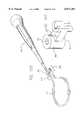
- One of these proceduresinvolves the use of a catheter having a lasso which is tightened around the appendage. RF energy is then transmitted to the appendage by way of the lasso to thermally fuse the walls of the appendage to one another, thereby isolating the appendage.
- Atrial fibrillation and flutterrequires the formation of long, thin lesions of different lengths and curvilinear shapes in heart tissue.
- Such long, curvilinear lesion patternsrequire the deployment within the heart of flexible ablating elements having multiple ablating regions.
- the formation of these lesions by ablationcan provide the same therapeutic benefits that the complex incision patterns that the surgical maze procedure presently provides, but without invasive, open heart surgery.
- ablating energymust be governed to avoid incidences of tissue damage and coagulum formation.
- the delivery of ablating energymust also be carefully controlled to assure the formation of uniform and continuous lesions, without hot spots and gaps forming in the ablated tissue.
- heart chambersvary in size from individual to individual. They also vary according to the condition of the patient.
- One common effect of heart diseaseis the enlargement of the heart chambers. For example, in a heart experiencing atrial fibrillation, the size of the atrium can be up to three times that of a normal atrium.
- Catheter-based ablation and atrial appendage isolationhave proven to be a significant advance over the conventional open heart surgery based approaches. Nevertheless, the inventors herein have determined that further improvements are possible.
- the inventors hereinhave determined that it can be quite difficult to accurately position an ablation electrode on the endocardium surface by manipulating the distal end of a relatively long catheter body from a remote handle. This is especially true with respect to left atrial sites.
- the present inventorshave also determined that fluoroscopy is a somewhat inaccurate method of visualizing the ablation electrodes during positioning and when determining whether the electrodes are in proper contact with tissue.
- a primary goal of any ablation procedureis to create contiguous lesions (often long, curvilinear lesions) without over-heating tissue and causing coagulum and charring.
- Tissue ablationoccurs at 50° C., while over-heating occurs at 100° C.
- the present inventorshave further determined that it can be difficult to produce tissue contact that will accomplish this result with an electrode mounted on the distal end of a relatively long catheter. This is especially true in those procedures where an electrode on the distal tip of the catheter is dragged along the tissue. Such dragging also makes accurate placement of the electrode very difficult.
- Other shortcomings identified by the present inventorsconcern the convective cooling effects of the blood pool on the electrodes. For example, the system power requirements must be high enough to compensate for the heat losses due to convective cooling.
- cooled tipOne proposed method of solving the over-heating problems associated with conventional ablation catheters is the so-called "cooled tip” approach.
- the tissue surfaceis cooled with a saline solution.
- the salineis somewhat useful in keeping the surface temperature below the over-heating temperature, the sub-surface tissue temperature can still rise well above 100° C. Such temperatures will cause gas within the sub-surface tissue to expand.
- the tissuewill tear or pop, which will result in perforations of the epicardial surface and/or the dislodging of chunks of tissue that can cause strokes.
- the present inventorshave determined that catheter-based procedures suffer from many of the same disadvantages discussed above, such as those concerning positioning and visualization. Additionally, the inventors herein have determined that the lasso can bunch up the tissue when the lasso is tightened and that tissue fusion would be improved if this bunching could be avoided.
- conventional ablation devicesinclude controls that are located either on the RF energy source, or on a foot pedal.
- the inventors hereinhave determined that such arrangements are inconvenient and can make it difficult to control power during a surgical procedure.
- the general object of the present inventionsis to provide an apparatus for positioning an operative element (such as an ablation electrode) within the body which avoids, for practical purposes, the aforementioned problems.
- an operative elementsuch as an ablation electrode
- one object of the inventionsis to provide tissue ablation systems and methods providing beneficial therapeutic results without requiring highly invasive surgical procedures.
- Another objective of the inventionsis to provide systems and methods that simplify the creation of complex lesions patterns in soft tissue, such as myocardial tissue in the heart.
- certain embodiments of one of the present inventionsinclude an electrode support structure carried at the distal end of a guide body.
- the support structureincludes a bendable stylet extending along an axis outside the distal end of the guide body.
- the structurealso includes at least one flexible spline leg having a near end attached to the distal end of the guide body and a far end extending beyond the distal end of the guide body and attached to the bendable stylet.
- the spline legis normally flexed between the distal guide body end and the bendable stylet in a first direction that extends along and radially outward of the axis of the stylet.
- At least one electrode elementis on the flexible spline.
- the structurefurther includes a control element to apply tension to the stylet. The tension bends the stylet, thereby flexing the spline leg in a second direction.
- the flexure of the spline leg in the first directionfacilitates intimate contact between the electrode element and tissue.
- the additional flexure by the stylet of the spline leg in the second directionmakes possible the creation of a diverse number of additional shapes and tissue contact forces.
- an electrode support structurein addition to bending the stylet, includes another control element that moves the stylet along its axis to increase or decrease flexure of the spline leg in the first direction. This additional control over the flexure of the spline leg further enhances intimate contact against tissue, regardless of variations in the dimensions of the surrounding tissue region.
- an electrode support structurethat includes a malleable stylet. The physician imparts a desired flexure to the spline leg in the second direction by bending the malleable stylet.
- an electrode support structureis provided in which the spline leg itself is malleable.
- Structures that embody the features of this inventionmake possible the creation of diverse number of shapes and contact forces to reliably achieve the type and degree of contact desired between electrode elements and targeted tissue areas, despite physiologic differences among patients.
- the structures and methodsinclude a probe for deployment within the heart.
- the probecarries at least one elongated flexible ablation element to which a bendable stylet is attached.
- the structures and methodapply tension to bend the stylet.
- the bending of the styletflexes the ablation element into a curvilinear shape along the contacted tissue region.
- a surgical device in accordance with one embodiment of another one of the present inventionsincludes a relatively short shaft, a bendable spline assembly associated with the distal end of the shaft and having a predetermined configuration, the spline assembly being adapted to collapse in response to external forces and expand when the forces are removed, and an operative element associated with the bendable spline.
- a substantially tubular membermay be positioned around the shaft. Movement of the substantially tubular member over the spline assembly will cause the spline assembly to collapse, while the spline assembly will expand to the predetermined configuration in response to a retraction of the substantially tubular member.
- an soft tissue coagulation probein accordance with one embodiment of one of the inventions includes a relatively short shaft defining a distal end and a proximal end, a handle associated with the proximal end of the shaft, and at least one soft tissue coagulation electrode associated with the shaft and located in spaced relation to the handle.
- a surgical device in accordance with another embodiment of this inventionincludes a relatively stiff shaft, a handle associated with the proximal end of the shaft, and a distal tip assembly associated with the distal end of the shaft, the distal tip assembly including a distal member, which is flexible and/or malleable, and an operative element carried by the distal member.
- a surgical device in accordance with another embodiment of this inventionincludes a shaft, a relatively stiff tubular member positioned around a predetermined portion of the shaft and movable relative thereto, a distal tip assembly associated with the distal end of the shaft and including a flexible distal member and an operative element carried by the distal member, and a pivot assembly associated with the distal end of the tubular member and a distal portion of the tip assembly.
- the above-described embodiments of this inventionmay be used in a method of treating atrial fibrillation wherein access to the heart is obtained by way of a thoracostomy.
- the operative elementis an ablation electrode.
- Such a methodmay also be used to treat atrial fibrillation during mitral valve surgery wherein access to the heart is obtained through a thoracostomy, thoracotomy or median sternotomy.
- the relatively short shaft and manner of insertionallows the ablation electrode to be easily inserted into the atrium and visually guided to the desired location.
- the ablation electrodes in the present devicedo not have to be guided by manipulating the relatively long shaft of an endovascular catheter. This makes the positioning of the electrodes within the heart easier and more accurate.
- Endocardial visualizationis also improved because surgical methods employing the present device allow the endocardium to be viewed directly with the naked eye, a fiberoptic camera or other imaging modalities. This eliminates the need for fluoroscopic images and reduces the amount of radiation required, as compared to catheter-based procedures.
- the shaft in the present devicecan be relatively stiff, as compared to a catheter shaft, because the present shaft does not have to travel through the tortuous vascular path to the heart.
- the additional stiffnessenhances torque transmission and provides superior and more reliable electrode-endocardium contact force.
- Surgical devices in accordance with this inventionmay also be used during procedures, such as valve replacement where the patient is on cardiopulmonary bypass, to create tissue lesions.
- proceduressuch as valve replacement where the patient is on cardiopulmonary bypass, to create tissue lesions.
- the electrodes elementswill not be in contact with the blood pool and, accordingly, will not be affected by the convective cooling.
- Surgical devices in accordance with the present inventionmay include a series of temperature controlled electrodes that allow a long lesion to be created in rapid fashion, i.e. in approximately 30 to 120 seconds.
- the ability of the present surgical devices and techniques to create lesionsrapidly allows procedures to be performed during bypass that, heretofore, could not due to the time constraints. For example, a conventional surgical maze procedure takes approximately 12 hours to complete (note that a portion of the procedure is performed while the patient is not on bypass), while such a procedure may be completed in approximately 5 to 15 minutes with the present devices and methods.
- the shaft and/or sheathmay be formed from a malleable material that a physician can bend into a desired configuration and remain in that configuration when released.
- the stiffness of such materialmust be at least such that the shaft and/or sheath (if present) will not bend under the forces applied thereto during a surgical procedure.
- the distal end of the devicemay also be malleable, thereby allowing the physician to bend the distal end of the device into a shape corresponding to the bodily structure to be acted upon.
- a surgical devicein accordance with one embodiment of another one of the present inventions includes a handle having at least one movable handle member, first and second support members operably connected to the handle, at least one of the support members being movable with respect to the other support member in response to movement of the at least one movable handle member, and at least one ablation electrode associated with the first support member.
- this inventionis especially useful in a method of isolating an atrial appendage.
- Access to the atriummay be obtained by, for example, a thoracostomy and the appendage may be captured between the support members.
- RF energyis then applied to the captured portion of the appendage to thermally fuse the walls of the appendage to one another.
- This methodprovides better heating and fusing than the lasso catheter-based approach because the tissue is not bunched up when captured between the support members, as it is when the lasso is tightened. Additionally, the disadvantages associated with the use of catheters in general are also avoided.
- a surgical device in accordance one embodiment of another of the present inventionsincludes an energy source, at least one energy transmission device, and a handle including an energy control device coupled to the energy source and to the at least one energy transmission device.
- the energy control deviceis adapted to selectively control the transmission of energy from the energy source to the at least one energy transmission device. Because the energy control device is located on the handle, which is necessarily grasped by the physician during surgical procedures, the present surgical device provides more convenient energy control than that found in conventional devices.
- energy controlmay be accomplished through the use of a remote energy control device that is connected to power unit, but located in close proximity to the patient or otherwise within the sterile zone of an operating room. Such an arrangement also provides more convenient energy control than that found in conventional devices.
- the power control interfaceis located on the handle of a surgical probe or on a remote control device, the power control aspect of the overall electrophysiological system can be more conveniently brought into the sterile zone because both the present surgical probe and remote control device are both readily sterilizable.
- Conventional power control interfacesare part of a power control unit that is not readily sterilizable.
- a coupling device in accordance with another of the present inventionscan also be used in conjunction with a probe having an energy transmission device on a support member.
- One embodiment of the coupling deviceincludes a base member adapted to be removably secured to a first portion of the probe's flexible support member and an engagement device connected to the base member and adapted to be removably secured to a second portion of the flexible support member.
- the coupling deviceenables a physician to form a distal loop in the support member when desired, thereby increasing the flexibility of the probe.
- a surgical method in accordance with another of the present inventionsincludes the steps of coagulating soft tissue and then forming an incision is the coagulated tissue. If the incision is no deeper than the coagulation, the incision will not result in significant bleeding. This process can be repeated until an incision of the desired depth is achieved.
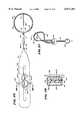
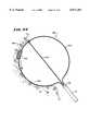
- FIG. 1is a plan view of an ablation probe having a full-loop structure for supporting multiple ablation elements.
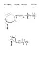
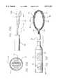
- FIG. 2is an elevation view of a spline used to form the loop structure shown in FIG. 1.
- FIG. 3is an elevation view of the distal hub used to form the loop structure shown in FIG. 1.
- FIG. 4is a side section view of the hub shown in FIG. 3.
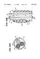
- FIG. 5is a perspective, partially exploded view of the spline, distal hub, and base assembly used to form the loop structure shown in FIG. 1.
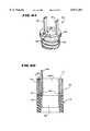
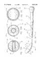
- FIG. 6ais an enlarged perspective view of the base assembly shown in FIG. 5.
- FIG. 6bis a side section view of an alternative base assembly for the loop structure shown in FIG. 1.
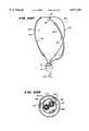
- FIG. 7is an elevation view of a half-loop structure for supporting multiple electrodes.
- FIG. 8is an elevation view of a composite loop structure for supporting multiple electrodes comprising two circumferentially spaced half-loop structures.
- FIG. 9is an elevation view of a composite loop structure comprising two full-loop structures positioned ninety degrees apart.
- FIG. 10is an elevation view, with parts broken away, of multiple electrode elements comprising segmented rings carried by a loop support structure.
- FIG. 11ais an enlarged view, with parts broken away, of multiple electrode elements comprising wrapped coils carried by a loop support structure.
- FIG. 11bis an elevation view, with parts broken away, of multiple electrode elements comprising wrapped coils carried by a loop support structure.
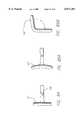
- FIG. 12is a top view of a steering mechanism used to deflect the distal end of the probe shown in FIG. 1.
- FIG. 13is a plan view of a full-loop structure for supporting multiple electrode elements having an associated center stylet attached to a remote control knob for movement to extend and distend the full-loop structure.
- FIG. 14is a side section view of the remote control knob for the center stylet shown in FIG. 13.
- FIG. 15is a plan view of the full-loop structure shown in FIG. 13, with the control knob moved to extend the full-loop structure.
- FIG. 16is a plan view of a full-loop structure shown in FIG. 13, with the control handle moves to distend the full-loop structure.
- FIG. 17is a plan view of a half-loop structure for supporting multiple electrode elements having an associated center stylet attached to a remote control knob for movement to extend and distend the half-loop structure.
- FIG. 18is a plan view of the half-loop structure shown in FIG. 17, with the control knob moved to extend the half-loop structure.
- FIG. 19is a plan view of a half-loop structure shown in FIG. 17, with the control handle moves to distend the half-loop structure.
- FIG. 20is a plan view of a full-loop structure for supporting multiple electrode elements having an associated center stylet attached to a remote control knob for movement to extend and distend the full-loop structure, and also having a remotely controlled steering mechanism to flex the center stylet to bend the full-loop structure into a curvilinear shape.
- FIG. 21is a side elevation view of the full-loop structure shown in FIG. 20.
- FIG. 22is an enlarged sectional view, generally taken along line 22--22 in FIG. 20, showing the steering wires attached to the center stylet to flex it.
- FIGS. 23a and 23bare side elevation views showing the operation of the steering mechanism in bending the full-loop structure, respectively, to the left and to the right.
- FIG. 24is a largely diagrammatic, perspective view of the full-loop structure bent to the right, as also shown in side elevation in FIG. 23b.
- FIG. 25is a plan view of the full-loop structure shown in FIG. 20 and the associated remote control knob for extending and distending as well as bending the full-loop structure.
- FIG. 26is a side section view, taken generally along lines 26--26 in FIG. 25, of the control knob for extending and distending as well as bending the full-loop structure.
- FIG. 27is a largely diagrammatic, perspective view of the full-loop structure when distended and bent to the right.
- FIG. 28is a largely diagrammatic, perspective view of a half-loop structure with steerable center stylet bent to the right.
- FIG. 29is a plan, partially diagrammatic, view of a full-loop structure for supporting multiple electrode elements having a movable spline leg attached to a remote control knob for movement to extend and distend the full-loop structure.
- FIG. 30ais a section view, taken generally along line 30a--30a in FIG. 29, of the interior of the catheter body lumen, through which the movable spline leg passes.
- FIG. 30bis a side section view of an alternative way of securing the full-loop structure shown in FIG. 29 to the distal end of the catheter tube.
- FIG. 31is a plan, partially diagrammatic view of the full-loop structure shown in FIG. 29 being extended by pulling the movable spline leg inward.
- FIGS. 32 and 33are plan, partially diagrammatic views of the full-loop structure shown in FIG. 29 being distended by pushing the movable spline leg outward.
- FIGS. 34 and 35are largely diagrammatic views of the full-loop structure shown in FIG. 29 being distended by pushing the movable spline leg outward while deployed in the atrium of a heart.
- FIGS. 36, 37, and 38are plan, partially diagrammatic views of a full-loop structure for supporting multiple electrode elements having two movable spline legs attached to remote control knobs for coordinated movement to extend and distend the full-loop structure.
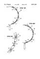
- FIG. 39ais a plan view of a full-loop structure for support multiple electrode elements having a smaller, secondary loop structure formed in one spline leg.
- FIG. 39bis a side view of the full-loop structure shown in FIG. 39a, showing the smaller, secondary loop structure.
- FIG. 40ais a perspective view of a modified full-loop structure for supporting multiple electrode elements having an odd number of three or more spline legs.
- FIG. 40bis a top section view of the base of the full-loop structure shown in FIG. 40a.
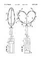
- FIGS. 41, 42, and 43are plan, partially diagrammatic, views of a bifurcated full-loop structure for supporting multiple electrode elements having movable half-loop structures to extend and distend the bifurcated full-loop structure.
- FIGS. 44 and 45are plan, partially diagrammatic, views of an alternative form of a bifurcated full-loop structure for supporting multiple electrode elements having movable center ring to extend and distend the bifurcated full-loop structure.
- FIG. 46is a plan, partially diagrammatic, views of an alternative form of a bifurcated full-loop structure for supporting multiple electrode elements having both a movable center ring and movable spline legs to extend and distend the bifurcated full-loop structure.
- FIGS. 47, 48, and 49are plan, partially diagrammatic, views of another alternative form of a bifurcated full-loop structure for supporting multiple electrode elements having movable half-loop structures to extend and distend the bifurcated full-loop structure.
- FIG. 50is a plan view of a full-loop structure for supporting and guiding a movable electrode element.
- FIG. 51is a side elevation view of the full-loop structure and movable electrode element shown in FIG. 50.
- FIG. 52is an enlarged view of the movable electrode supported and guided by the structure shown in FIG. 50, comprising wound coils wrapped about a core body.
- FIG. 53is an enlarged view of another movable electrode that can be supported and guided by the structure shown in FIG. 50, comprising bipolar pairs of electrodes.
- FIG. 54is a largely diagrammatic view of the full-loop structure and movable electrode element shown in FIG. 50 in use within the atrium of a heart.
- FIG. 55is a perspective, elevation view of a bundled loop structure for supporting multiple electrode elements, comprising an array of individual spline legs structures, each having a movable portion that independently extends and distends the individual structures to shape and flex the overall bundled loop structure.
- FIG. 56is a top view of the bundled loop structure shown in FIG. 55.
- FIG. 57is a perspective elevation view of the bundled loop structure shown in FIG. 55 with some of the independently movable spline legs extended and distended to change the flexure of the bundled loop structure.
- FIG. 58is a top view of the bundled loop structure shown in FIG. 57.
- FIGS. 60a and 60bare, respectively, top and side views of a bundled loop structure like that shown in FIG. 57, with some of the independently movable spline legs extended and distended to change the flexure of the bundled loop structure, to bring it into contact with the surrounding atrial wall.
- FIG. 61is a top section view of the base of the bundled loop structure shown in FIG. 55.
- FIG. 63is an end view of the surgical device shown in FIG. 62.
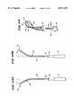
- FIG. 64ais a side view of a surgical device for positioning an operative element within a patient in accordance with another preferred embodiment of one of the present inventions.
- FIG. 64bis a partial side view of a portion of the surgical device shown in FIG. 64a.
- FIG. 65is a side, partial section view of a portion of the surgical device shown in FIG. 64a.
- FIG. 66is a side view of a surgical device for positioning an operative element within a patient in accordance with still another preferred embodiment of one of the present inventions.
- FIG. 67ais a partial side, cutaway view of a surgical device for positioning an operative element within a patient in accordance with yet another preferred embodiment of one of the present inventions.
- FIG. 67bis a section view taken along line 67b--67b in FIG. 67a.
- FIG. 68is a section view showing an operative element coated with regenerated cellulose.
- FIG. 69ais a section view showing a partially masked operative element.
- FIG. 69bis a section view showing an alternative operative element configuration.
- FIGS. 70a-70care front views of a spline assembly in accordance with an embodiment of one of the present inventions.
- FIG. 70dis a side view of the spline assembly shown in FIGS. 70a-70c.
- FIG. 70eis a section view taken along line 70e--70e in FIG. 70a.
- FIG. 70fis a partial front, partial section view of a surgical device for positioning an operative element within a patient in accordance with yet another preferred embodiment of one of the present inventions.
- FIG. 71ais a side view of a surgical device for positioning an operative element within a patient in accordance with a preferred embodiment of one of the present inventions.
- FIG. 71bis a side, partial section view of an alternate tip that may be used in conjunction with the device shown in FIG. 71a.
- FIG. 71cis a side, section view of another alternate tip that may be used in conjunction with the device shown in FIG. 71a.
- FIG. 71dis a perspective view of a probe handle in accordance with a present invention.
- FIG. 71eis a perspective view of a probe handle in accordance with another embodiment of present invention.
- FIG. 71fis an exploded perspective view of a probe in accordance with one embodiment of a present invention.
- FIG. 71gis an enlarged view of a portion of the probe shown in FIG. 71f.
- FIG. 71his a plan view of an electrophysiology system in accordance with one embodiment of a present invention.
- FIG. 72ais a section view of the distal portion of the device shown in FIG. 71a taken along line 72a--72a in FIG. 71a.
- FIG. 72ba section view of an alternate distal portion for the device shown in FIG. 71a.
- FIG. 72cis a side, partial section view of another alternative distal portion for the device shown in FIG. 71a.
- FIG. 73is a section view taken along line 73--73 in FIG. 71a.
- FIG. 74is a side view of a surgical device for positioning an operative element within a patient in accordance with another preferred embodiment of one of the present inventions.
- FIG. 75is a side view of a surgical device for positioning an operative element within a patient in accordance with yet another preferred embodiment of one of the present inventions.
- FIG. 76is a perspective view of a portion of the device shown in FIG. 75.
- FIG. 77is a side view of a surgical device for positioning an operative element within a patient in accordance with still another preferred embodiment of one of the present inventions.
- FIG. 78is a side view of a clamp in accordance with a preferred embodiment of one of the present inventions.
- FIG. 79is a section view taken along line 79--79 in FIG. 78.
- FIG. 80is a top view of the clamp illustrated in FIG. 78.
- FIG. 81is a side view of a surgical device for positioning an operative element within a patient and applying a clamping force to a bodily structure in accordance with a preferred embodiment of one of the present inventions.
- FIG. 82is a side view of a surgical device for positioning an operative element within a patient and applying a clamping force to a bodily structure in accordance with another preferred embodiment of one of the present inventions.
- FIG. 83is a side view of a surgical device for positioning an operative element within a patient and applying a clamping force to a bodily structure in accordance with still another preferred embodiment of one of the present inventions.
- FIG. 84is a top view of the operative element supporting member of the surgical device shown in FIG. 83.
- FIG. 85bis a top view of still another operative element supporting member.
- FIG. 86is a side view of a surgical device for positioning an operative element within a patient and applying a clamping force to a bodily structure in accordance with yet another preferred embodiment of one of the present invention.
- FIG. 87is a side, partial section view of an exemplary procedure involving the surgical device shown in FIG. 81.
- FIG. 88is a side, partial section view of an exemplary procedure involving a surgical device having an alternate support member configuration.
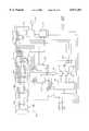
- FIGS. 89 and 90are schematic views of a system for controlling the application of ablating energy to multiple electrodes using multiple temperature sensing inputs.
- FIG. 91is a schematic flow chart showing an implementation of the temperature feedback controller shown in FIGS. 89 and 90, using individual amplitude control with collective duty cycle control.
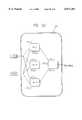
- FIG. 92is a schematic view of a neural network predictor, which receives as input the temperatures sensed by multiple sensing elements at a given electrode region and outputs a predicted temperature of the hottest tissue region.
- FIG. 93is a fragmentary side view showing the use of a grabbing catheter in conjunction with a lasso catheter for maintaining the walls of the inverted appendage together.
- FIG. 94is a fragmentary view of the combination shown in FIG. 93 illustrating further steps of tying an appendage in an inverted orientation.
- FIG. 95is a perspective view of a pressure application probe in accordance with a preferred embodiment of a present invention secured to an operative element supporting probe.
- FIG. 96is an enlarged perspective view of the pressure application probe shown in FIG. 95.
- FIG. 97is a partial perspective view of a pressure application probe in accordance with another preferred embodiment of a present invention.
- FIG. 98is a perspective view of a coupling device in accordance with a preferred embodiment of a present invention.
- FIG. 99is a perspective view showing a pressure application probe and the coupling device shown in FIG. 98 being used in combination with the surgical device shown in FIG. 71a.
- FIG. 100is a perspective view showing the coupling device shown in FIG. 98 being used in combination with the surgical device shown in FIG. 71a.
- FIG. 101is a perspective view of a coupling device in accordance with another preferred embodiment of a present invention.
- This specificationdiscloses a number of electrode structures, mainly in the context of cardiac ablation, because the structures are well suited for use with myocardial tissue. Nevertheless, it should be appreciated that the structures are applicable for use in therapies involving other types of soft tissue. For example, various aspects of the present inventions have applications in procedures concerning other regions of the body such as the prostate, liver, brain, gall bladder, uterus and other solid organs.
- FIG. 1shows a multiple electrode probe 10 that includes a loop structure 20 carrying multiple electrode elements 28.
- the loop structurecan carry one or more of the other operative elements discussed in Section III below.
- the probe 10includes a flexible catheter tube 12 with a proximal end 14 and a distal end 16.
- the proximal end 14carries an attached handle 18.
- the distal end 16carries a loop structure 20 that supports multiple electrodes.
- the loop support structure 20comprises two flexible spline legs 22 spaced diametrically opposite each other.
- the dual leg loop structure 20 shown in FIG. 1will be called a "full-loop" structure.
- the far ends of the spline legs 22radiate from a distal hub 24.
- the near ends of the spline legs 22radiate from a base 26 attached to the distal end 16 of the catheter tube 12.
- the multiple electrode elements 28are arranged along each spline leg 22.
- the two spline legs 22 of the structure 20are paired together in an integral loop body 42 (see FIG. 2).
- Each body 42includes a mid-section 44 from which the spline elements 22 extend as an opposed pair of legs.
- the mid-section 44includes a preformed notch or detent 46, whose function will be described later.
- the loop body 42is preferably made from resilient, inert wire, like Nickel Titanium (commercially available as Nitinol material). However, resilient injection molded inert plastic or stainless steel can also be used.
- the spline legs 22comprise thin, rectilinear strips of resilient metal or plastic material. Still, other cross sectional configurations can be used.
- the distal hub 24has a generally cylindrical side wall 50 and a rounded end wall 52.
- a longitudinal slot 56extends through the hub 24, diametrically across the center bore 54.
- the hub 24is made of an inert, machined metal, like stainless steel.
- the bore 54 and slot 56can be formed by conventional EDM techniques. Still, inert molded plastic materials can be used to form the hub 24 and associated openings.
- a spline leg 22 of the hoop-like body 42is inserted through the slot 56 until the mid-body section 44 enters the bore 54.
- the detent 46snaps into the bore 54 (see FIG. 4) to lock the body 42 to the hub 24, with the opposed pair of spline legs 22 on the body 42 radiating free of the slot 56 (see FIG. 5).
- the base 26includes an anchor member 62 and a mating lock ring 64.
- the anchor member 62fits with an interference friction fit into the distal end 16 of the catheter tube 12.
- the lock ring 64includes a series of circumferentially spaced grooves 66 into which the free ends of the spline legs 22 fit.
- the lock ring 64fits about the anchor member 62 to capture with an interference fit the free ends of the spline legs 22 between the interior surface of the grooves 66 and the outer surface of the anchor member 62 (see FIG. 6).
- the anchor member 62/lock ring 64 assemblyholds the spline elements 22 in a desired flexed condition.
- the base 26can comprise a slotted anchor 63 carried by the distal end 16 of the catheter tube 12.
- the slotted anchor 63is made of an inert machined metal or molded plastic material.
- the slotted anchor 63includes an outer ring 65 and a concentric slotted inner wall 67.
- the interior of the anchor 63defines an open lumen 226 to accommodate passage of wires and the like between the catheter tube bore 36 and the support structure 20 (as will be described in greater detail later).
- the inner wall 67includes horizontal and vertical slots 69 and 71 for receiving the free ends of the spline legs 22.
- the free endspass through the horizontal slots 69 and are doubled back upon themselves and wedged within the vertical slots 71 between the outer ring 65 and the inner wall 67, thereby securing the spline legs 22 to the anchor 63.
- the full-loop structure 20 shown in FIG. 1does not include a hub 24 like that shown in FIGS. 1 and 3, and, in addition, does not incorporate a detented integral loop body 42 like that shown in FIG. 2.
- Any single full-loop structure without a center stiffener or styletpreferably comprises a single length of resilient inert wire (like Nickel Titanium) bent back upon itself and preformed with resilient memory to form the desired full loop shape.
- Structure 112 in FIG. 29(which will be described in greater detail later) exemplifies the use of a preshaped doubled-back wire to form a loop, without the use of a hub 24 or detented loop body 42.
- FIG. 7shows an alternative loop structure 20(1) that includes a single spline leg 22(1) carrying multiple electrode elements 28.
- This single leg loop structurewill be called a "half-loop" structure, in contrast to the dual leg loop structure 20 (i.e., the "full-loop structure) shown in FIG. 1.
- the half-loop structure 20(1) shown in FIG. 7the hoop-like body 42 shown in FIG. 2 is cut on one side of the detent 46 to form the single spline leg 22(1).
- the single spline leg 22(1)is snap-fitted into the hub 24 and captured with an interference fit by the anchor member 62/lock ring 64 assembly of the base 26 in the manner just described (shown in FIGS. 5 and 6a).
- the single spline leg 22(1)can be wedged within the base anchor ring 63 shown in FIG. 6b.
- the half-loop structure 20(1)also includes a center stiffener 40 passing through the base 26 and to the bore 54 of the hub 24.
- the stiffener 40can be made of a flexible plastic like PEEK, or from a hollow tube like hypo-tubing or braid plastic tubing.
- loop-type configurationsbesides the full-loop structure 20 and half-loop structure 20(1) are possible.
- two half-loop structures 20(1), one or both carrying electrode elements 28,can be situated in circumferentially spaced apart positions with a center stiffener 40, as FIG. 8 shows.
- four half-loop structures, or two full-loop structurescan be assembled to form a three-dimensional, basket-like structure 60 (without using a center stiffener 40), like that shown in FIG. 9.
- the electrode elements 28can serve different purposes.
- the electrode elements 28can be used to sense electrical events in heart tissue.
- the principal use of the electrode elements 28is to emit electrical energy to ablate tissue.
- the electrode elements 28are conditioned to emit electromagnetic radio frequency energy.
- the electrode elements 28can be assembled in various ways.
- the elementscomprise multiple, generally rigid ring electrode elements 30 arranged in a spaced apart, segmented relationship upon a flexible, electrically nonconductive sleeve 32 which surrounds the underlying spline leg 22.
- the sleeve 32is made a polymeric, electrically nonconductive material, like polyethylene or polyurethane.
- the electrode rings 30are pressure fitted about the sleeve 32.
- the flexible portions of the sleeve 32 between the rings 30comprise electrically nonconductive regions.
- the electrode segments 30can comprise a conductive material coated upon the sleeve 32. The electrode coating can be applied either as discrete, closely spaced segments or in a single elongated section.
- spaced apart lengths of closely wound, spiral coilsare wrapped about the sleeve 32 to form an array of segmented, generally flexible electrodes 34.
- the inherent flexible nature of a coiled electrode structures 34also makes possible the construction of a continuous flexible ablating element comprising an elongated, closely wound, spiral coil wrapped about all or a substantial length of the flexible sleeve 32.
- the electrode elements 28can be present on all spline legs 22, as FIG. 1 shows, or merely on a selected number of the spline legs 22, with the remaining spline legs serving to add structural strength and integrity to the structure.
- Various access techniquescan be used to introduce the probe 10 and its loop support structure 20 into the desired region of the heart.
- the physiciancan direct the probe 10 through a conventional vascular introducer through the femoral vein.
- the physiciancan direct the probe 10 through a conventional vascular introducer retrograde through the aortic and mitral valves.
- each flexible ablation elementcarries at least one and, preferably, at least two, temperature sensing elements 68.
- the multiple temperature sensing elements 68measure temperatures along the length of the electrode element 28.
- the temperature sensing elements 68which can comprise thermistors or thermocouples, can be located on the ablation elements in the manner shown in FIGS. 10 and 11a/b.
- the temperature sensing elements 68can be located on one or both of the longitudinal end edges of the ablation elements, as shown in U.S. patent application Ser. No. 08/788,782, entitled “Systems and Methods for Controlling Ablation Using Multiple Temperature Sensing Elements,” which is incorporated herein by reference.
- the handle 16 and catheter body 12preferably carry a steering mechanism 70 (see FIGS. 1 and 12) for selectively bending or flexing the distal end 16 of the catheter body 12.
- the steering mechanism 18can vary.
- the steering mechanism 70includes a rotating cam wheel 72 with an external steering lever 74 (see FIG. 1).
- the cam wheel 72holds the proximal ends of right and left steering wires 76.
- the steering wires 76like the signal wires 58, pass through the catheter body lumen 36.
- the steering wires 76connect to the left and right sides of a resilient bendable wire or spring (not shown) enclosed within the distal end 16 of the catheter body 12. Forward movement of the steering lever 74 flexes or curves the distal end 16 down. Rearward movement of the steering lever 74 flexes or curves the distal end 16 up.
- the loop support structure 20 or 20(1)must make and maintain intimate contact between the electrode elements 28 and the endocardium.
- This inventionprovides loop support structures that the physician can adjust to adapt to differing physiologic environments.
- the adjustable full-loop structure 78includes a flexible stylet 80 attached at its distal end to the hub bore 54.
- the stylet 80can be made from a flexible plastic material, like PEEK, or from a hollow tube, like hypo-tubing or braid plastic tubing.
- the proximal end of the stylet 80attaches to a control knob 82 in the handle 18 (as FIG. 13 shows).
- the control knob 82moves within a groove 84 (see FIGS. 13 and 14) in the handle 18 to impart fore and aft movement to the stylet 80.
- Stylet movementchanges the flexure of the structure 78.
- the symmetric expansionpresses the electrode elements 28 into intimate surface contact against the endocardium.
- the symmetric expansionstabilizes the position of the loop structure 78 within the atrium 88.
- the resilience of the spline legs 22, further compressed by the pulled-back stylet 80maintains intimate contact between the electrode elements 28 and atrial tissue, without trauma, as the heart expands and contracts.
- the push-pull stylet 80can also be used in association with a half-loop structure 90, like that previously shown and discussed in FIG. 7.
- FIGS. 20 and 21show a full-loop structure 92 that includes a center stylet 94, which can be flexed.
- the flexing of the center stylet 94bends the spline legs 22 in a second direction different than the radial direction in which they are normally flexed.
- this second directionis generally perpendicular to the axes of the spline legs 22, as FIGS. 23a/b and 24 show, although acute bends that are not generally perpendicular can also be made.
- the bending of the spline legs 22 in this fashionmakes possible the formation of long, thin curvilinear lesions using a full-loop structure 92, or (as will be described later) in a half-loop structure 110, as well.
- the stylet 94is made from a metal material, for example stainless steel 17-7, Elgiloy material, or Nickel Titanium material.
- a pair of left and right steering wires, respectively 96(R) and 96(L)is attached to opposite side surfaces of the stylet 94 near the hub 24, by adhesive, soldering, or by suitable mechanical means.
- the steering wires 96(R) and 96(L)are attached to the stylet side surfaces in a diametric opposite orientation that is at right angles to the radial orientation of the spline legs 22 relative to the stylet 94.
- the steering wires 96(R) and 96(L)extend along the stylet 94, through the base 26 and catheter body lumen 36, and into the handle 18 (see FIG. 25).
- a tube 98surrounds the stylet 94 and steering wires 96(R) and 96(L), at least along the distal, exposed part of the stylet 94 within the structure 92, keeping them in a close relationship.
- the tube 98can be heat shrunk to fit closely about the stylet 94 and steering wires 96(R) and 96(L).
- a groove 100 in the handlecarries a control assembly 102.
- the stylet 94is attached to the control assembly 102, in the manner already described with respect to the control knob 82 in FIGS. 13 and 14. Sliding movement of the control assembly 102 within the groove 100 imparts fore and aft movement to the stylet 94, thereby distending or extending the loop structure 92.
- the electrode elements 28(which in FIGS. 20 to 27 comprises a continuous coil electrode 34, described earlier) likewise bend to the left.
- twisting the steering lever 108 clockwiseapplies tension to the right steering wire 96(R), bending the loop structure 92 to the right (as FIGS. 23b and 24 show).
- the electrode elements 28likewise bend to the right.
- bent electrode elements 28conforming to the bent spline legs 22, assume different curvilinear shapes, depending upon amount of tension applied by the steering wires 96(R) and 96(L). When contacting tissue, the bent electrode elements 28 form long, thin lesions in curvilinear patterns.
- the splines 22themselves can also be made of a malleable material, like annealed stainless steel, or untreated stainless steel 17-7, or untreated Nickel Titanium.
- the most distal parts of the malleable splines 22are heat treated to maintain their shape and not collapse during introduction and deployment in the vascular system. This will also give the overall structure greater stiffness for better contact with the tissue. It also gives the physician the opportunity to bend the structure to form long, thin, lesions in prescribed curvilinear patterns set by the malleable splines.
- the physiciancan also control the radial dimensions of the loop structure 94 in concert with controlling the curvilinear shape of the loop structure 92, as FIG. 27 shows. A diverse array of radial sizes and curvilinear shapes is thereby available.
- a half-loop structure 110can also include a fixed or movable stylet 94 with steering wires 96(R) and 96(L).
- the use of the same handle-mounted control assembly 102/rotatable cam 104 assembly shown in FIGS. 25 and 26 in association with the half-loop structure 110makes possible the creation of diverse curvilinear shapes of variable radii.
- a malleable stylet 94 and malleable splinescan be used.
- FIGS. 29 to 35show a full-loop structure 112 in which only one spline leg 114 is attached to the base 26.
- the fixed spline leg 114is preformed with resilient memory to assume a curve of a selected maximum radius (shown in FIG. 33).
- the other spline leg 116located diametrically opposed to the fixed spline leg 114, extends through the base 26 and catheter body lumen 36 (see FIGS. 30a and 30b) into the handle 18.
- the spline leg 116slides fore and aft with respect to the base 26. Movement of the spline leg 116 changes the flexure of the structure 1 12.
- any single full-loop structure without a center stiffener or styletcan comprise a single length of wire bent back upon itself and preformed with resilient memory to form the desired full loop shape.
- the single full-loop structure 20 shown in FIG. 1can, in an alternative construction, be made without a hub 24 and a detented loop body 42, and instead employ a preshaped doubled-back wire to form a loop, like the structure 20.
- FIG. 30bshows an alternative way of securing the fixed spline leg 114 to the distal end 16 of the catheter tube 12, without using a base 26.
- the free end of the fixed spline leg 114lies against the interior of the tube 12.
- the leg 114passes through a slit 115 formed in the catheter tube 12.
- the leg 114is bent back upon itself in a u-shape to lie against the exterior of the tube 12, wedging the tube 12 within the u-shape bend 117.
- a sleeve 119is heat shrunk about the exterior of the tube 12 over the region where the u-shape bend 117 of the spline leg 114 lies, securing it to the tube 12.
- a metallic ring(not shown) can be used to secure the spline leg 114 to the tube 12.
- the movable spline leg 116 and wires 58pass through the interior bore 36 of the catheter tube 12, as before described.
- the proximal end of the spline leg 116(see FIG. 29) is attached to a movable control knob 82 carried in a groove 84 on the handle 18, like that shown in FIG. 13. Movement of the control knob 82 within the groove 84 thereby imparts fore-and-aft movement to the spline leg 116.
- the fixed spline leg 114carries electrode elements 28 in the manner already described.
- the movable spline leg 116is free of electrode elements 28. Still, it should be appreciated that the movable spline leg 116 could carry one or more electrode elements 28, too.
- FIGS. 31 to 33show, moving the control knob 82 forward slides the movable spline leg 116 outward, and vice versa.
- the movable spline leg 116applies a counter force against the resilient memory of the fixed spline leg 114, changing the flexure and shape of the loop structure 112 for vascular introduction and deployment in contact with tissue.
- the counter forcecontracts the radius of curvature of the fixed spline leg 114 against its resilient memory.
- Pushing the movable spline leg 116 outwardallows the resilient memory of the fixed spline leg 114 to expand the radius of curvature until the selected maximum radius is achieved.
- the counter force appliedchanges the flexure and shapes the fixed spline leg 114 and the resilient curvature or shape to the full-loop structure 118 itself.
- Coordinated opposed movement of both spline legs 120/122(as FIGS. 37 and 38 show) using the control knobs 124/126 allows the physician to elongate the curvature of the loop structure 118 into more of an oval shape, compared to more circular loop structures 112 formed using a single movable leg 116, as FIGS. 31 to 33 show.
- FIGS. 39a and 39bshow an alternative full-loop structure 128 having one spline leg 130 that is fixed to the base 26 and another spline leg 132, located diametrically opposed to the fixed spline 130, that is movable fore and aft with respect to the base 26 in the manner already described.
- the movable spline leg 132can carry electrode elements 28 (as FIG. 39a shows), or be free of electrode elements, depending upon the preference of the physician.
- the smaller, secondary full-loop structure 134makes possible the formation of annular or circumferential lesion patterns encircling, for example, accessory pathways, atrial appendages, and the pulmonary vein within the heart.
- the movable spline leg 132compresses the secondary full-loop structure 134, urging and maintaining it in intimate contact with the targeted tissue area.
- FIGS. 40a and 40bshow a modified full-loop structure 216 having an odd number of spline legs 218, 220, and 222.
- the structure 216includes two spline legs 218 and 220 that, in the illustrated embodiment, are fixed to the base 26 about 120° apart from each other. As FIG. 40b shows, the base 26 is generally like that shown in FIG. 6b, with the slotted anchor 63 in which the near ends of the legs 218 and 220 are doubled back and wedged.
- the structure 216also includes a third spline leg 222 that, in the illustrated embodiment, is spaced about 120° from the fixed spline legs 218/220. As FIG.
- the near end of the third spline leg 222is not attached to the base 26, but passes through the inner lumen 226 into the lumen 36 of the catheter tube 12.
- the third spline leg 222is thereby movable fore and aft with respect to the base 26 in the manner already described.
- all spline legs 218, 220, and 222can be fixed to the base 26, or more than one spline leg can be made moveable.
- a hub 24 like that shown in FIGS. 3 and 4includes circumferentially spaced slots 56 to accommodate the attachment of the three splines 218, 220, and 222.
- the fixed splines 218 and 220carry electrode elements 28 (as FIG. 40a shows), while the movable spline 22 is free of electrode elements.
- FIG. 40bshow, the wires 58 coupled to the electrode elements 28 pass through the anchor lumen 226 for transit through the catheter tube bore 36.
- the orientation of the fixed splines 218 and 220 relative to the movable spline 222thereby presents an ablation loop 224, like the secondary loop structure 134 shown in FIGS. 39a/b, that lies in a plane that is generally transverse of the plane of the movable spline 222.
- other orientations of an odd number of three or more spline legscan be used.
- the movable spline leg 222extends and compresses the secondary structure 134 to urge and maintain it in intimate contact with the targeted tissue area.
- a center stylet to further contract and distend the ablation loop 224can also be incorporated, with or without a stylet steering mechanism.
- FIGS. 41, 42, and 43show a variation of a loop structure, which will be called a bifurcated full-loop structure 136.
- the structure 136(see FIG. 41) includes two oppositely spaced splines legs 138 and 140, each carrying one or more electrode elements 28.
- the near end of each spline leg 138/140is attached to the base 26.
- the far end of each spline leg 138/140is attached a stylet 142 and 144.
- Each spline leg 138/140is preformed with resilient memory to achieve a desired maximum radius of curvature (which FIG. 41 shows).
- the spline leg stylets 142/144are joined through a junction 146 to a common control stylet 148.
- the common control stylet 148passes through the catheter body lumen 36 to a suitable slidable control knob 150 in the handle 18, as already described. By sliding, the control knob 150 moves the control stylet 148 to change the flexure of the spline legs 138/140.
- the spline legs 138/140form individual half-loop structures (like shown in FIG. 7) that together emulate a full-loop structure (like that shown in FIG. 1), except for the presence of a connecting, distal hub 24.
- the bifurcated structure 136emulates the full-loop structure 78, when distended (as FIG. 16 shows).
- FIGS. 44 and 45show an alternative embodiment of a bifurcated full-loop structure 152.
- the structure 152includes two oppositely spaced spline legs 154/156, each carrying one or more electrode elements 28, like the structure 136 shown in FIGS. 41 to 43.
- Each spline leg 154/156is preformed with a resilient memory to assume a desired maximum radius of curvature (which FIG. 44 shows).
- the structure 152 shown in FIGS. 44 and 45fixes both ends of the spline legs 154/156 to the base 26.
- the spline legs 154/156thereby form stationary, side-by-side half-loop structures, each with an inner portion 158 and an outer portion 160. Together, the stationary half-loop structures create the bifurcated full-loop structure 152.
- a center stylet 162is attached to a ring 164 that commonly encircles the inner portions 158 of the spline legs 154/156 along the center of the structure 152. Movement of the stylet 162 slides the ring 164 along the inner leg portions 158. The stylet 162 passes through the catheter body lumen 36 to a suitable control in the handle (not shown), as already described.
- Forward movement of the ring 164(as FIG. 45 shows) jointly extends the spline legs 154/156, creating a low profile for vascular introduction. Rearward movement of the ring 164 (as FIG. 44 shows) allows the resilient memory of the preformed spline legs 154/156 to bow the legs 154/156 outward into the desired loop shape.
- FIG. 46shows another alternative embodiment of a bifurcated full-loop structure 166.
- This structure 166has two oppositely spaced spline legs 168 and 170, each carrying one or more electrode elements 28.
- Each spline leg 168/170is preformed with a resilient memory to assume a maximum radius of curvature (which FIG. 46 shows).
- each spline leg 168/170is attached to the base 26.
- the far end of each spline leg 168/170is individually attached to its own stylet 172/174.
- the spline stylets 172/174 of the structure 166individually pass through the catheter body lumen 36 to suitable control knobs (not shown) in the handle 18.
- a third stylet 176is attached to a ring 178 that encircles the spline stylets 172 and 174.
- the third stylet 176passes through the guide tube lumen 36 to its own suitable control knob (not shown) in the handle 18.
- FIG. 46allows the physician to move the ring 178 up and down along the spline stylets 172 and 174 to shape and change the flexure of the structure 166 in the manner shown in FIGS. 44 and 45. Independent of this, the physician can also individually move the spline stylets 172 and 174 to further shape and change the flexure of each spline leg 168 and 170, as in the case of the movable spline legs 120/122 shown in FIGS. 36 to 38.
- This structure 166thus gives the physician latitude in shaping the loop structure to achieve the desired contact with the atrial wall.
- FIGS. 47 to 49Another alternative embodiment of a bifurcated full-loop structure 180 is shown in FIGS. 47 to 49.
- the structure 180includes two oppositely spaced spline legs 182 and 184, each carrying one or more electrode elements 28.
- Each spline leg 182/184is preformed with a resilient memory to assume a desired maximum radius of curvature (which FIG. 49 shows).
- each spline leg 182/184is attached to the base 26.
- a stationary ring 190encircles the inner portions 186 near the distal end of the structure 180, holding them together.
- each spline leg 182/184is free of attachment to the base 26 and is resiliently biased away from the base 26.
- Each outer portion 188is individually attached to its own stylet 192 and 194.
- the spline stylets 192 and 194individually pass through the catheter body lumen 36 to suitable control knobs (not shown) in the handle 18.
- the spline stylets 192/194can be manipulated together or individually to achieve the shape and flexure desired.
- FIGS. 50 and 51show a full-loop structure 196 which supports a movable ablation element 198.
- the structure 196includes a pair of spline legs 200 secured at their distal ends to the hub 24 and at their proximal ends to the base 26, in the manner described in association with the structure shown in FIG. 1.
- a center stiffener 202extends between the base 26 and the hub 24 to lend further strength.
- the ablation element 198(see FIG. 52) comprises a core body 204 made of an electrically insulating material.
- the body 204includes a central lumen 206, through which one of the spline legs 200 passes.
- the core body 204slides along the spline leg 200 (as shown by arrows in FIGS. 50 to 52).
- a coil electrode element 34(as already described) is wound about the core body 204.
- the core body 204can be coated with an electrically conducting material or have an electrically conducting metal band fastened to it.
- the ablation elementcan also comprise a composite structure 198(1) (see FIG. 53) of two bi-polar electrodes 208 separated by an electrically insulating material 210.
- the core body 204 of the electrodecan range in diameter from 3 Fr to 8 Fr and in length from 3 mm to 10 mm.
- a guide wire 212is attached to at least one end of the ablation electrode 198 (see FIGS. 50 and 52).
- the guide wire 212extends from the handle 18 through the catheter body lumen 36, along the center stiffener 202 and through the hub 24 for attachment to the ablation element 198.
- a signal wire 214also extends in common along the guide wire 212 (see FIG. 52) to supply ablation energy to the electrode 198.
- the proximal end of the guide wire 212is attached to a suitable control knob (not shown) in the handle 18. Movement of the guide wire 212 forward pushes the ablation element 198 along the spline leg 200 from the distal end of the structure 196 to the proximal end.
- Two guide wiresmay be used (as FIG. 52 shows), which are attached to opposite ends of the ablation element 198. Pulling on one guide wire 212 advances the electrode 198 toward the distal end of the structure 196, while pulling on the other guide wire 213 advances the electrode 198 in the opposite direction toward the proximal end of the structure 196.
- the distal tip of a second catheter bodycan be detachably coupled either magnetically or mechanically to the movable electrode 198. In this implementation, the physician manipulates the distal end of the second catheter body into attachment with the electrode 198, and then uses the second catheter body to drag the electrode 198 along the structure 196.
- the ablation electrode 198In use (as FIG. 54 shows), once satisfactory contact has been established with the atrial wall 86, sliding the ablation electrode 198 along the spline leg 200 while applying ablation energy creates a long and thin lesion pattern.
- the ablationcan be accomplished by either moving the electrode 198 sequentially to closely spaced locations and making a single lesion at each location, or by making one continuous lesion by dragging the electrode 198 along the tissue while ablating.
- One or both spline legs 200can also be movable with respect to the base, as before described, to assure intimate contact between the ablation element 198 and the endocardium.
- the structure 228 shown in FIGS. 55 to 58comprises four spline legs (designated L1, L2, L3, and L4) circumferentially spaced ninety degrees apart.
- Each spline leg L1, L2, L3, and L4is generally like that shown in FIG. 29.
- Each leg L1, L2, L3, and L4is preformed with resilient memory to assume a curve of selected maximum radius.
- each leg L1 to L4carries at least one electrode element 28, although one or more of the legs L1 to L4 could be free of electrode elements 28.
- each spline leg L1 to L4are attached to the structure base 26.
- the base 26is similar to that shown in FIG. 30b, having an outer ring 236 and a concentric slotted inner element 238, through which the near ends of the outer spline leg portions 230 extend. The near ends are doubled back upon themselves and wedged in the space 240 between the outer ring 236 and inner element 238, as earlier shown in FIG. 6b.
- each spline leg L1, L2, L3, and L4are not attached to the base 26. They pass through lumens 242 in the inner element 238 of the base 26 (see FIG. 61) and into catheter body lumen 36 for individual attachment to control knobs 234 on the handle 18 (see FIG. 55). wires 58 associated with the electrode elements 28 carried by each leg L1 to L4 pass through other lumens 244 in the inner element 238 (see FIG. 61).
- each spline leg L1 to L4is independently movable, in the same way as the spline leg shown in FIGS. 31 to 35.
- the physiciancan change the normal flexure of the structure 228 (which FIGS. 55 and 56 show) to a new flexure (which FIGS. 57 and 58 show), by altering the shape each spline leg L1 to L4 independent of each other.
- FIGS. 57 and 58show, the inner portion 232 of leg L4 has been pulled aft, compressing the associated loop.
- the inner portion 232 of leg L2has been pushed forward, expanding the associated loop.
- FIGS. 59a/b and 60a/bshow, by selective manipulation of the movable inner portions 232 of the spline legs L1 to L4, the physician can adjust the shape of the three dimensional loop structure 228 within the atrium 88 from one that fails to make sufficient surface contact between the electrode element 28 and the atrial wall 86 (as FIGS. 59a/b show) to one that expands the atrium 88 and creates an extended region of surface contact with the atrial wall 86 (as FIGS. 60a/60b show). The physician can thereby tailor the shape of the three dimensional structure 228 to the particular physiology of the patient.
- the inner portions 232 of the spline legs L1 to L4can be fixed to the base 26 and the outer portions 230 made free to move in the manner shown in FIGS. 47 to 49.
- one or more movable spline legscan be used in association with a movable center stylet to provide control of the shape and flexure of the ablation element.
- the further inclusion of steering wires on the movable stylet, or the use of a malleable stylet and/or malleable spline legsadds the ability to form curvilinear lesion patterns.
- FIGS. 31 to 38show
- a movable center styletas FIGS. 13 to 19 show
- a stylet steering assembly or malleable stylet/splinesas FIGS. 20 to 28 show.
- Such a structureis capable of creating a diverse number of shapes and contact forces to reliably achieve the type and degree of contact desired between the ablation elements and the targeted tissue area, despite physiologic differences among patients.
- any of the loop structures like those described hereincan be mounted at the end of hand-held probe for direct placement by the physician in contact with a targeted tissue area.
- a hand held loop structure carrying multiple electrodescan be manipulated by a physician to ablate tissue during open heart surgery for mitral valve replacement.
- a surgical device (or probe") 250 for positioning an operative element 252 within a patientincludes a relatively short shaft 254 and a bendable spline assembly 256, associated with the distal end of the shaft, for supporting the operative element.
- the operative element 252is in the form of a plurality of electrode elements 294, as discussed in greater detail in Section III below.
- the relatively short shaftmay be between approximately 4 and 18 inches in length, and is preferably 8 inches in long, while the outer diameter of the shaft is preferably between approximately 6 and 24 French.
- the spline assembly 256has a predetermined use configuration. In the exemplary embodiment shown in FIGS.
- the spline assemblyincludes a pair of spline legs 258 and 260 and an annular member 262 which supports the operative element 252.
- the surgical devicealso includes a tubular member 264 (a cylindrically shaped sheath in the exemplary embodiment) which covers a portion of the shaft 254 and is also slidable relative thereto.
- the spline assembly 256is adapted to collapse (the insertion configuration) in response to movement of the substantially tubular member 264 in the distal direction and to expand to the predetermined use configuration when the substantially tubular member is moved in the proximal direction.
- a handle 266may be provided on the proximal end of the shaft 254.
- the tubular member 264preferably includes a raised gripping surface 268.
- FIGS. 64a-65Another exemplary surgical device (or “probe") for positioning an operative element within a patient, which is generally represented by reference numeral 270, is illustrated in FIGS. 64a-65.
- the surgical deviceincludes a substantially triangularly shaped spline assembly 272 that consists of first and second side legs 274 and 276 and a distal leg 278.
- the distal leg 278,which is preferably non-linear from end to end and approximately 10 to 12 cm in length, includes first and second linear portions 280 and 282 and a bent portion 284 located mid-way between the ends.
- This spline configurationprovides a spring force against the selected bodily surface during use (such as the atrium wall in a cardiac procedure) and the bend in the distal leg 278 optimizes the contact between the operative element 252 and the selected surface.
- the spline assembly 272will collapse in the manner shown in FIG. 65 when the tubular member 264 is advanced thereover and will return to the orientation shown in FIG. 64a when the tubular member is retracted.
- the surgical device 270also includes a second handle 267.
- the handle 266(FIG. 62) or 267 (FIG. 64a) is grasped by the physician and force is applied through the shaft 254 and side legs 258 and 260 (FIG. 62) or 274 and 276 (FIG. 64a) to the operative element supporting annular member 262 (FIG. 62) or distal leg 278 (FIG. 64a).
- the shaft and side legsshould be sufficiently strong to prevent collapse when the force is applied.
- the fact that the present devicesare not passed through a tortured vascular path to the site of interest allows the shaft and spline legs to be stiffer than a conventional catheter shaft.
- the shaft 254 and side legs 274 and 276 in the embodiment shown in FIGS. 64a and 65may be configured such that they collapse and form a semicircle with the distal leg 278 when force is applied to the shaft (note FIG. 64b).
- the operative elementshould be appropriately masked in one of the manners described below to limit contact of the operative element to the intended bodily structure.
- a guidewire 286may be used to direct and/or anchor the distal leg 278 of the exemplary spline assembly 272 in an anatomical anchor site (such as one of the pulmonary veins shown in FIG. 66).
- the guidewire 286passes through a lumen in the shaft 254.
- the distal end of the guidewire 286passes through a lumen 288 formed in one of the spline assembly side legs 274 and 276, while the proximal end is secured to a handle 290.
- two guide wiresmay be used to anchor the spline assembly 272 in two anatomical anchor sites. Both wires would extend to the same handle.
- FIGS. 62-66may also be provided without the tubular member 264.
- Such devicesare especially useful in surgical procedures associated with a thoracotomy or a median sternotomy, where the spline assemblies can be easily collapsed and advanced to the desired location, or advanced into the desired location without being collapsed.
- the spline assembliescan be malleable, if desired, as opposed to simply being bendable.
- an endoscope 292may be passed through one lumen in a tubular member 264' that has a pair of lumens.
- the shaft 254 and endoscope 292can pass through a common lumen.
- the spline assemblies illustrated in FIGS. 62-66are preferably made from resilient, inert wire, like nickel titanium (commercially available as Nitinol material) or 17-7 stainless steel. However, resilient injection molded inert plastic can also be used.
- the wire or molded plasticis covered by suitable biocompatible thermoplastic or elastomeric material such as PEBAX® or Pellethane®.
- PEBAX® or Pellethane®suitable biocompatible thermoplastic or elastomeric material
- the various portions of the spline assembliescomprises a thin, rectilinear strips of resilient metal or plastic material. Still, other cross-sectional and longitudinal configurations can be used.
- the spline legscan decrease in cross-sectional area in a distal direction, by varying, e.g., thickness or width or diameter (if round), to provide variable stiffness along its length. Variable stiffness can also be imparted by composition changes in materials or by different material processing techniques.
- the distal leg 278may be configured such that the leg is flat at the distal end, but becomes more semicircular in cross-section as the leg becomes more proximal in order to taper the stiffness profile and prevent lateral movement of the spline assembly.
- the curvature of the spline legsmay also be varied and the lateral ends of the distal leg may be reinforced in order to provide more lateral stability.
- the spline assembly of the probe shown in FIGS. 64a and 65may be replaced by a curved spline assembly 300.
- the spline assemblyincludes a flat, inert wire 302 (preferably formed from Nitinol) that acts as a spring and an outer portion 304 (preferably formed from PEBAX® or Pellethane®).
- the flat wire 302has a long side and a short side. The short sides lie in planes that are parallel to the plane shown in FIG. 70d.
- the spline assembly 300will deflect in the manner shown in FIGS. 70b and 70c when "in plane" forces F are applied to the spline assembly.
- the assemblywill resist bending when "out of plane” forces are applied in the manner shown in FIG. 70d.
- itmay be used to form an arcuate lesion during, for example, a procedure where a lesion is formed around the pulmonary vein.
- the wire 302does not have to be rectangular in cross-section as shown. Other cross-sectional shapes where the length is greater than the width can also be used.
- the wire 302can also be made from a malleable material such as partially or fully annealed stainless steel instead of the spring-like material discussed above. The malleable embodiments will enable the operator to form fit the ablation element support structure to irregular anatomical structures.
- exemplary spline assembly 300'includes first and second steering wires 301a and 301b that are secured to the spring-like flat wire 302 by, for example, welding, mechanical crimping or adhesive bonding.
- the proximal ends of the steering wires 301a and 301bare operably connected to a knob 303 on a handle 266' by way of a cam (not shown).
- the handle 266'is substantially similar to the handle 266 shown in FIG. 62, but for the knob 303, cam and provisions for the steering wires 301a and 301b. Rotation of the knob 303 will cause the spline assembly to move side to side in, for example, the manner illustrated in FIG. 70c.
- the physicianwill be able to move the operative element 252 within the patient by rotating the knob 303.
- Such movementis useful when the physician is attempting to precisely locate the operative element within the patient and/or control the contact force between the operative element and the tissue surface. This is especially true when the handle and or shaft 254 cannot be moved, due to anatomical or surgical constraints.
- the steering wires 301a and 301bare both secured at about the midpoint of the flat wire loop.
- Other configurationsare possible depending on the configuration of the loop that is desired after the knob 303 is rotated.
- one wirecould be secured closer to the top of the loop than the other.
- the shape of the cammay also be varied. More detailed discussions of the use of steering wires, albeit in conventional catheter settings, can be found in commonly assigned U.S. Pat. Nos. 5,195,968, 5,257,451, and 5,582,609, which are incorporated herein by reference.
- the shaft 254is preferably relatively stiff.
- the phrase "relatively stiff"means that the shaft (or other structural element) is either rigid, malleable, or somewhat flexible.
- a rigid shaftcannot be bent.
- a malleable shaftis a shaft that can be readily bent by the physician to a desired shape, without springing back when released, so that it will remain in that shape during the surgical procedure.
- the stiffness of a malleable shaftmust be low enough to allow the shaft to be bent, but high enough to resist bending when the forces associated with a surgical procedure are applied to the shaft.
- a somewhat flexible shaftwill bend and spring back when released.
- the force required to bend the shaftmust be substantial.
- Rigid and somewhat flexible shaftsare preferably formed from stainless steel, while malleable shafts are formed from annealed stainless steel.
- One method of quantifying the flexibility of a shaftis to look at the deflection of the shaft when one end is fixed in cantilever fashion and a force normal to the longitudinal axis of the shaft is applied somewhere between the ends.
- Such deflection ( ⁇ )is expressed as follows:
- Wis the force applied normal to the longitudinal axis of the shaft
- Lis the length of the shaft
- Xis the distance between the fixed end of the shaft and the applied force
- Eis the modulous of elasticity
- Iis the moment of inertia of the shaft.
- deflectionWhen the force is applied to the free end of the shaft, deflection can be expressed as follows:
- the stiffness of a shaftis a function of the product of E and I. This product is referred to herein as the "bending modulus.”
- Eis a property of the material that forms the shaft
- Iis a function of shaft geometry, wall thickness, etc. Therefore, a shaft formed from relatively soft material can have the same bending modulus as a shaft formed from relatively hard material, if the moment of inertia of the softer shaft is sufficiently greater than that of the harder shaft.
- the bending modulus rangesare based on the amount of force, applied at and normal to the free end of the longitudinal axis of the cantilevered shaft, that is needed to produce 1 inch of deflection from an at rest (or no deflection) position.
- the deflection of a shaftdepends on the composition of the shaft as well as its moment of inertia.
- the shaftcould be made of elastic material, plastic material, elasto-plastic material or a combination thereof.
- the surgical toolis better adapted to the constraints encountered during the surgical procedure.
- the force required to bend a relatively stiff 2 inch long shaftshould be in the range of approximately 1.5 lbs. to approximately 12 lbs.
- the force required to bend a 2 inch piece of conventional catheter shaftshould be between approximately 0.2 lb. to 0.25 lb.
- such force valuesconcern the amount of force, applied at and normal to the free end of the longitudinal axis of the cantilevered shaft, that is needed to produce 1 inch of deflection from an at rest (or no deflection) position.
- Ductile materialsare preferable in many applications because such materials can deform plastically before failure due to fracturing.
- Materialsare classified as either ductile or brittle, based upon the percentage of elongation when the fracture occurs. A material with more than 5 percent elongation prior to fracture is generally considered ductile, while a material with less than 5 percent elongation prior to fracture is generally considered brittle.
- Material ductilitycan be based on a comparison of the cross sectional area at fracture relative to the original cross area. This characteristic is not dependent on the elastic properties of the material.
- the shaftcould be a mechanical component similar to shielded (metal spiral wind jacket) conduit or flexible Loc-Line, which is a linear set of interlocking ball and socket linkages that can have a center lumen. These would be hinge-like segmented sections linearly assembled to make the shaft.
- the exemplary tubular member 264 illustrated in FIGS. 62-67bis preferably in the form of a relatively thin cylindrical sheath (e.g., with a wall thickness of about 0.005 inch) and has an outer diameter which is preferably less than 0.180 inch.
- the sheath materialis preferably also lubricious, to reduce friction during movement of the sheath relative to the shaft 254 and spline assemblies 256 and 272.
- materials made from polytetrafluoroethylene (PTFE)can be used for the sheath.
- PTFEpolytetrafluoroethylene
- the distal end of the sheathshould be relatively flexible to prevent injury.
- additional stiffnesscan be imparted to the remaining portion of the sheath by lining the sheath with a braided material coated with PEBAX® material (comprising polyethel block amide related to nylon).
- PEBAX® materialcomprising polyethel block amide related to nylon.
- Other compositions made from PTFE braided with a stiff outer layer and other lubricious materialscan be used.
- tubular member 264may be relatively stiff and formed from the materials described above with respect to the shaft 254.
- a surgical probe 308 in accordance with another embodiment of this inventionincludes a relatively stiff shaft 310, a handle 312 and a distal section 314.
- the shaft 310consists of a hypo-tube 316, which is either rigid or relatively stiff, and an outer polymer tubing 318 over the hypo-tube.
- a relatively stiff tubeeither malleable or somewhat flexible, will preferably have a bending modulus of between approximately 3 lb.-in. 2 and approximately 50 lb.-in. 2 .
- the handle 312is similar to the handle 266 discussed above in that it includes a PC board 320 for connecting the operative elements on the distal portion of the probe to a power source.
- the handle 312preferably consists of two molded handle halves and is also provided with strain relief element 322.
- An operative element 254(here, in the form of a plurality of electrode elements 294) is provided on the distal section 314. This embodiment is particularly useful because it can be easily inserted into the patient through an introducing port such as a trocar.
- the handle 312 shown in FIG. 71ais intended to be used in a conventional power supply configuration, wherein power transmission from an RF generator (or other energy source) to the electrodes 294 is controlled by a foot switch.
- a handle 312'is provided with a manually operable on-off switch 313.
- On-off switch 313allows the physician to selectively enable and disable the supply of RF ablation energy (and other types of power) to the electrode(s) on the distal portion of the probe.
- the exemplary handle 312" shown in FIG. 71ealso includes a plurality of individual on-off switches 315 for each of the electrodes.
- the individual on-off switches 315allow the physician to selectively control the supply of power to individual electrodes.
- the exemplary handle 312" which has seven individual on-off switches 315,is preferably used in a probe having seven electrodes. If for example, the physician intends to ablate tissue with only three of the electrodes, then the three chosen electrodes may be enabled by way of the corresponding switches 315 prior to placing the global on-off switch 313 in the "on" position.
- a plurality of indicator elements 317are also provided on the exemplary handle 312" shown in FIG. 71e.
- the indicator elements 317are in the form of buttons that are raised when a corresponding on-off switch 315 is depressed. This provides the physician with a tactile as well as visual indication of the on-off status of the switches 315.
- the indicator elements 317may also be in the form of indicator lights. Sound-based indications of the on-off status of the switches 315 may also be used. For example, a speaker on the handle or the power supply device may be employed to periodically indicate which of the switches 315 are in the "on" position.
- a probemay be configured such that the handle is re-usable and the remaining portions of the probe are disposable or separately re-usable.
- exemplary handle 312"includes an edge-type connector having a first portion 319 on the handle and a second portion 321 on the remaining portion of the probe.
- the remaining portionis primarily the shaft 310 which, as described above, supports a plurality of electrode elements (not shown).
- the first and second connector portions 319 and 321have elements that will mechanically couple the handle to the remaining portion of the probe and release the two when desired.
- the first and second connector portionswill also connect signal wires from the electrodes (or other operative elements) and temperature sensors to the energy source.
- a locking mechanism(not shown) may be used to maintain the integrity of the connection between the two connector portions.
- a cable 323may be provided to connect the handle to an energy source.
- FIGS. 71e-71gmay be used with any of the probes disclosed herein and the features of such handles may be incorporated into any of the other handles disclosed herein.
- a remote power control unit 325may be used in conjunction with a surgical probe 308 or a catheter (not shown).
- the remote power control unit 325includes a main body 327a and a plurality of on/off switches 327b. Preferably, there is one on/off switch 327b for each electrode and, in the illustrated embodiment, there are seven electrodes and seven on/off switches.
- the remote power control unitcan also include a global power on/off switch (not shown). Alternatively, a foot pedal (not shown) may be provided to perform the same function.
- the size and shape of the remote power control unit 325allow it to be easily grasped in one hand by the physician or other member of the operating room staff.
- the remote power control unit 325is about 8 inches in length, about 1.5 inches in width and about 0.5 inches in thickness.
- the size and shapecan be adjusted to suit particular needs.
- the remote power control unit 325may be used in conjunction with conventional electrophysiology power control units, such as that shown in U.S. Pat. No. 5,545,193, that are connected to a source of energy (such as ablation energy) and provide individual electrode control.
- the remote control deviceincludes a connection apparatus which, in the illustrated embodiment, consists of a cable 329a and a connector 329b.
- the cable 329ashould be relatively long, i.e. between about 6 feet and about 15 feet in length and is preferably 10 feet.
- the connection apparatuscan also be in the form of a wireless transmitter/receiver arrangement or any other suitable device.
- the surgical probe 308is also connected to the electrophysiology power control unit. When a foot pedal is used, it too is connected to the electrophysiology power control unit.
- the exemplary remote power control unit 325includes indicia 333 in the shape of the distal portion of a surgical probe, indicator lights 335, and numbers corresponding to the respective electrodes on the probe. The combination of indicia, lights and numbers allows the physician to readily determine which electrodes are enabled and which electrodes are disabled.
- the surgical probe 308(as well as the other probes disclosed herein) and the remote power control unit 325 are sterilizable. To that end, these devices are either entirely hermetically sealed or selected portions, such as those enclosing electronic components, are sealed. Those components which are not sealed are penetrable by a gas sterilant, such as ethylene oxide (EtO).
- a gas sterilantsuch as ethylene oxide (EtO).
- EtOethylene oxide
- the hypo-tube 316may be the heat treated malleable hypo-tube 316 shown in FIGS. 71a, 73 and 74.
- one section of the hypo-tubepreferably the distal section
- the distal sectioncan be made more malleable than the other. This will alleviate any discontinuity between the distal section 314 and the shaft 310 when the distal section is malleable.
- a plurality of temperature sensing elementsmay be located on, under, abutting the longitudinal end edges of, or in between, the electrode elements 294 in any of the exemplary devices disclosed herein.
- a reference temperature sensing elementmay be provided.
- a reference temperature sensing 324may be located in the handle so that room temperature will be used as the reference as shown in FIG. 71a.
- the reference temperature sensormay, alternatively, be provided on or near the distal tip of the device. Another alternative is to use an electronic circuit to function as the reference temperature sensor.
- a reference temperature sensorcan also be placed on the patient or in the operating room and the physician can simply input the reference temperature into the power control device.
- the accuracy of the reference temperature sensoris less important in applications where the patient is on bypass because the convective cooling effects of blood flowing past the electrodes is substantially reduced. Also, the present surgical devices provide better tissue contact than conventional catheter-based devices, which provides more accurate temperature monitoring.
- the distal section 314can be either somewhat flexible, in that it will conform to a surface against which it is pressed and then spring back to its original shape when removed from the surface or, as noted above, malleable. A bending modulus of between 3 lb.-in. 2 and 50 lb.-in. 2 is preferred.
- a somewhat flexible distal section 314may include a spring member 330, which is preferably either a solid flat wire spring (as shown), a round wire, or a three leaf flat wire Nitinol spring, that is connected to the distal end of the hypo-tube 316.
- Other spring membersformed from materials such as 17-7 or carpenters steel, may also be used.
- a series of lead wires 332 and 334connect the electrode elements 294 and temperature sensor elements, respectively, to the PC board 320.
- the spring member 330 and leads wires 332 and 334are enclosed in a flexible body 336, preferably formed from PEBAX® material, polyurethane, or other suitable materials.
- the spring member 330may also be pre-stressed so that the distal tip is pre-bent in the manner shown in FIG. 71a.
- an insulating sleeve 331may be placed between the spring member 330 and the lead wires 332 and 334.
- the spring member 330may be replaced by a mandrel 337 made of suitably malleable material such as annealed stainless steel or beryllium copper, as illustrated for example in FIG. 72b.
- the mandrelwill ideally be fixed to the distal tip of the device (by, for example, soldering, spot welding or adhesives) and run through the shaft into the handle where it will also be fixed to insure good torque transmission and stability of the distal tip.
- the malleable mandrelmay be fixed directly within the distal end of the shaft's hypo-tube 316 and secured by, for example, soldering, spot welding or adhesives.
- a slot 339may be formed in the hypotube 316'.
- the malleable mandrel 337is inserted into the slot 339 and then held in place by spot welds 341 (shown), solder or adhesive.
- the slot 339includes an opening 341 at one end thereof through which the mandrel 337 extends.
- the slot 339could also include another opening at the other end.
- the slot 339is located in spaced relation to the proximal end of the hypotube 316' to create additional support for the mandrel 337 when it is bent and formed into various shapes.
- the distal portion 314may also be formed by a hypo-tube that is simply a continuation of the shaft hypo-tube 316.
- the distal end hypo-tubecan be a separate element connected to the shaft hypo-tube 316, if it is desired that the distal end hypo-tube have different stiffness (or bending) properties than the shaft hypo-tube.
- the shaft 310may be from 4 inches to 18 inches in length and is preferably 6 to 8 inches.
- the distal portion 314may be from 1 inch to 10 inches in length and is preferably 2 to 3 inches.
- the distal portion 314preferably includes six spaced electrode elements 294 that are approximately 12 mm in length. The number and length of the electrode elements 294 can, of course, be varied to suit particular applications.
- the distal section 314may be provided with a distal (or tip) electrode.
- the distal electrode 326may be a solid electrode with a through hole for one or more temperature sensors.
- Another exemplary electrodeis the shell electrode 328 shown in FIG. 71c, which could also have one or more temperature sensors inside.
- the distal electrodeshave a variety of applications. For example, a distal electrode may be dragged along an anatomical surface to create a long lesion.
- the distal electrodemay also be used to touch up lesions (straight or curvilinear) created by electrode elements 294 if, for example, the distal section 314 does not exactly conform to the anatomical surface, and to continue lesions formed by the electrode elements.
- the distal electrodemay also be used to create lesions in anatomical ridges that are shaped such that the integrity of the surgical device would be compromised if the distal section 314 were bent to conform to the ridge.
- an exemplary surgical probe 340is provided with a pull wire 342 that allows the physician to adjust the curvature of the distal portion 314 from no curve, to a slight curve, an extreme curve, or even a loop, as desired.
- the pull wire distal portion 344is connected to the distal tip of distal section 314.
- the distal portion of the pull wireenters the shaft proximal to the ablation electrodes, and the proximal portion 346 exits through an aperture formed in the handle 312.
- the probe 340is substantially the same as the spring tip probe version shown in FIGS. 71 a and 72a.
- the proximal portion of the pull wire 342may be associated with a handle/knob arrangement such as that shown in FIG. 70f.
- a surgical probe 348is provided with a distal loop structure 350 that includes an operative element 252 in the form of a plurality of electrodes 294.
- the distal loop structure 350which extends through an opening 352 in a sheath 354, is connected to a shaft 356.
- the shaftis, in turn, connected to the handle 312.
- the proximal portion of the sheath 354includes a handle 358 that allows the sheath to be moved distally and proximally.
- the stiffness of the loop structure 350is less than that of the sheath 354.
- the loop structure 350will bulge out of the sheath opening 352 in the manner shown in FIG. 75.
- the loop structure 350will slide back into the sheath such that the sheath and the loop structure are coaxial.
- the exemplary loop structure 350is similar to the distal portion 314 of the probe shown in FIGS. 71a and 72a in that it includes a spring member (not shown), such as a leaf spring or a flat wire spring (preferably formed from Nitinol), which is covered by a flexible material such as a PEBAX® tube 359.
- a spring membersuch as a leaf spring or a flat wire spring (preferably formed from Nitinol)
- a flexible materialsuch as a PEBAX® tube 359.
- the spring membercan be flat so that it also provides resilience which helps the distal portion conform to the anatomical surface of interest and prevents "out of plane bending.”
- a pivot assembly 360is provided on the distal end of the sheath 354.
- the pivot assembly 360includes a base member 362 and a pivot member 364 which is secured to the base member by a pivot pin 366.
- the pivot member 364pivots within a slot 368 that is formed in the base member 362.
- the size and shape of the slot 368, and the location of the pivot member 364 therein,may be adjusted to adjust the shape of the loop.
- the location of the pivot member 364 and the shape and size of the slot 368may be varied such that the pivot member can only rotate 30, 60, 90 or 180°. However, up to 270° of rotation is possible.
- the pivot member 364includes a connector 372 (such as the illustrated threaded or barbed connector) for securing the distal end of the loop structure 350 to the pivot member.
- the rigidity, malleability, or flexibility of the probe 348may be provided in a number of ways.
- the sheath 354may be formed from a rigid stainless steel hypo-tube, a relatively stiff somewhat flexible stainless steel hypotube, or a relatively stiff malleable annealed stainless steel hypo-tube.
- the shaft 356may be a rigid (or somewhat flexible) stainless steel hypo-tube or a malleable annealed stainless steel hypo-tube. In either case, the distal end 374 of the shaft 356 will abut the flexible portion of the loop structure 350.
- Other materialscan, of course, be used in place of stainless steel.
- a rigid high durometer plastic tubefor example, may be substituted for the stainless steel hypo-tube in the sheath or shaft.
- the sheathmay be secured to the shaft by a touhy borst connector 376 that is secured to the distal end of the sheath 354 between the handle 358 and the handle 312.
- the probeincludes a shaft 380 (similar to shafts 254, 310 or 356 described above) on which one or more ablation electrodes 294 are mounted. As described in greater detail in Section III below, masking 296 may be used to control the focus of the ablation energy and/or prevent convective cooling when the probe is in the blood pool.
- a handle 266is also provided.
- the shaft 380is preferably between approximately 4 and 16 inches in length, between approximately 3 and 8 mm in diameter. Additionally, the shaft may either be rigid or relatively stiff and, if relatively stiff, can be either malleable or somewhat flexible.
- the ablation probe 378may be used for a variety of procedures. For example, the shaft may be inserted into the heart to perform ablation procedures.
- a pressure application probe 650may be used to apply pressure to the distal section of a probe, such as the probe 308 shown in FIG. 71a, or any other operative element supporting device.
- the application of pressure with the probe 650can improve the level of contact between tissue and, for example, the distal section 314 of the probe 308.
- the pressure application probe 650includes an elongate main body portion 652 and at least one engagement device 654.
- the exemplary pressure application probe shown in FIGS. 95 and 96also includes a second engagement device 658. As discussed in detail below, the second engagement device 658 has a slightly different shape than the engagement device 654.
- the main body portion 652is preferably either rigid, malleable or somewhat flexible and about 4 inches to about 18 inches in length, although the length may be adjusted to suit particular applications.
- the main body portion 652may be formed in the manner described above with respect to the shaft 254, and preferably consists of a soft metal rod or tube, or a settable plastic rod or tube.
- the shaft 254may be formed from a nickel titanium rod or tube, which is ductile at room temperature and which will straighten out at elevated temperatures such as those used during autoclave sterilization. Regardless of stiffness, the outer surface of the main body portion 652 should be covered with insulating material such as PEBAX® or urethane.
- the engagement device 654is preferably formed from insulating material such as polycarbonate, urethane, glass filled thermoplasticor ABS.
- the engagement devicemay have any of a variety of configurations.
- the engagement devices 654 and 658are generally c-shaped, with engagement device 658 having a more open shape.
- the c-shapehelps maintain the engagement devices at the desired location on the distal portion of the surgical probe 308 so that pressure can be applied to the desired location.
- the open shape of the engagement device 658allows the engagement device to be readily repositioned along the distal portion of the surgical probe without disturbing the position of the surgical probe relative to the tissue.
- the c-shaped engagement device 654can be coupled to the distal section 314 of the probe 308 as shown in FIG. 95, or any other probe, by either inserting the distal tip of the probe through the opening 656 or by snap-fitting the engagement device 654 over the distal section.
- the engagement deviceshould be somewhat flexible. This arrangement allows the pressure application probe 650 to be rotated relative to the probe 308 when the two are engaged. As a result, the pressure application probe 650 can be reoriented without moving the probe 308.
- the pressure application probe 650may also be used to move the probe 308 within the patient when the two are engaged.
- an exemplary pressure application probe 660is provided with an engagement device 662 having a relatively narrow profile.
- the narrow profileallows the probe 660 to engage the distal section of an operative element supporting device, such as the distal section 314 of probe 308, even when the two devices are oriented at severe angles relative to one another.
- the engagement deviceis not limited to the shapes shown in FIGS. 95-97. Any shape that is capable of engaging the distal portion of a probe may be used.
- the pressure application probes shown in FIGS. 95-97are especially useful in thoroscopic procedures.
- the pressure application probemay be inserted into a patient through one port, while the electrode supporting probe is inserted through another port and connected to the pressure application probe.
- the exemplary coupling device 664includes a base member 666, a generally c-shaped engagement device 668 (similar to that described above) and, in the illustrated embodiment, a connecting member 670.
- the base member 666 and engagement device 668can also be directly connected to one another.
- the coupling device 664has a wide range of uses.
- the coupling devicemay part of a pressure application probe 672, as shown in FIG. 99.
- Another exemplary use of the coupling device 664is shown in FIG. 100.
- the coupling device 664is placed on a probe such as probe 308 and used to create a distal loop.
- the coupling devicecan be located at different points along the length of the probe and arranged at different rotational orientations relative to the probe (note arrows 674a and 674b) in order to control the shape of the loop.
- the base member 666 and a portion of the distal section 314can include respective sets of teeth that allow the rotational orientation of the coupling device 664 to be fixed relative to the probe 308. Note teeth 676 in FIG. 101.
- the connecting member 670may be configured in a variety of ways.
- the connecting member 670can be rigid, flexible, somewhat flexible, or malleable.
- the connecting member 670can also be in the form of a swivel or pivot.
- the base member 666 and engagement device 668can also be fixed at various angles relative to one another (note, for example, FIG. 99).
- the principal use of the electrode elementsis to transmit electrical energy and, more particularly, RF energy, to ablate heart tissue.
- the electrode elementscan also be used to sense electrical events in heart tissue.
- the electrode elementscan serve to transmit electrical pulses to measure the impedance of heart tissue, to pace heart tissue, or to assess tissue contact using conventional pacing and sensing techniques. Once the physician establishes contact with tissue in the desired heart region, the physician applies ablating energy to the electrode elements.
- the electrode elements 28are electrically coupled to individual wires 58 (see FIG. 11a) to conduct ablating energy to them.
- the wires 58extend along the associated spline leg 22 (as FIG. 11a shows), through a suitable access opening provided in the base 24 (for example, the anchor lumen 226 shown in FIG. 6b) into and through the catheter body lumen 36 (as generally shown in FIG. 1 and FIGS. 30a/b), and into the handle 18, where they are electrically coupled to external connectors 38 (see FIG. 1).
- the connectors 38plug into a source of RF ablation energy (not shown).
- the electrode elements 294are electrically coupled to individual wires (see reference numeral 295 FIGS. 69b and 70e and reference numeral 332 in FIGS. 72a, 72b and 73) to conduct ablating energy to them.
- the wiresare passed in conventional fashion through a lumen extending through one of the spline legs and the shaft 254 into a PC board in the handle 266, where they are electrically coupled to a connector 296 which is received in a port 298 (see FIG. 62).
- the connector 296plugs into a source of RF ablation energy.
- a plurality of temperature sensing elementsmay also be provided on the spline assemblies shown herein. Such temperature sensing elements may be located on, under, abutting the longitudinal end edges of, or in between, the electrode elements 294.
- signals from the temperature sensor elementsare transmitted to the source of ablation energy by way of wires (see reference numeral 297 in FIGS. 69b and 70e and reference numeral 334 in FIGS. 72a, 72b and 73) which are also connected to the PC board.
- wiressee reference numeral 297 in FIGS. 69b and 70e and reference numeral 334 in FIGS. 72a, 72b and 73
- the electrode elementscan be assembled in various ways. They can, for example, comprise multiple, generally rigid electrode elements arranged in a spaced apart, segmented relationship.
- the segmented electrodescan each comprise solid rings of conductive material, like platinum, which makes an interference fit about the annular spline member.
- the electrode segmentscan comprise a conductive material, like platinum-iridium or gold, coated upon the device using conventional coating techniques or an ion beam assisted deposition (IBAD) process. For better adherence, an undercoating of nickel or titanium can be applied.
- IBADion beam assisted deposition
- the electrodescan also be in the form of helical ribbons.
- the electrode elementscan comprise spaced apart lengths of closely wound, spiral coils wrapped about the device to form an array of generally flexible electrode elements.
- the coilsare made of electrically conducting material, like copper alloy, platinum, or stainless steel, or compositions such as drawn-filled tubing (e.g. a copper core with a platinum jacket).
- the electrically conducting material of the coilscan be further coated with platinum-iridium or gold to improve its conduction properties and biocompatibility.
- Electrode elementscan be formed with a conductive ink compound that is pad printed onto a non-conductive tubular body.
- a preferred conductive ink compoundis a silver-based flexible adhesive conductive ink (polyurethane binder), however other metal-based adhesive conductive inks such as platinum-based, gold-based, copper-based, etc., may also be used to form electrodes. Such inks are more flexible than epoxy-based inks.
- the electrode elementscan also include a porous material coating 299, which transmits ablation energy through an electrified ionic medium.
- a porous material coating 299which transmits ablation energy through an electrified ionic medium.
- electrode elements and temperature sensor elementsmay be coated with regenerated cellulose, hydrogel or plastic having electrically conductive components.
- the coatingacts as a mechanical barrier between the surgical device components, such as electrodes, preventing ingress of blood cells, infectious agents, such as viruses and bacteria, and large biological molecules such as proteins, while providing electrical contact to the human body.
- the regenerated cellulose coatingalso acts as a biocompatible barrier between the device components and the human body, whereby the components can now be made from materials that are somewhat toxic (such as silver or copper).
- coating electrodes with regenerated cellulosedecreases the effect of convective cooling on the electrode because regenerated cellulose is a poor thermal conductor as compared to metal.
- the effect of convective cooling by blood flowing past the regenerated cellulose coated electrodesis diminished. This provides better control for a lesion-generating process because the hottest tissue temperature is closer to the ablation electrode.
- the regenerated cellulose coatingdecreases the edge effects attributed to delivering RF energy to an electrode having a sharp transition between the conductive electrode and insulating material.
- the current density along the electrode and power density within tissueare more uniform, which reduces the incidence and severity of char and/or coagulum formation.
- the more uniform current density along the axis of the devicealso results in a more uniform temperature distribution at the electrode, which decreases the requirement for precise placements of the temperature sensors at the ablation electrodes.
- by coating a device with regenerated cellulose to create the outer surfaceless labor-intensive methods of forming electrodes and bonding wires to electrode surfaces can be used.
- a devicesuch as the one of the above-described distal spline assemblies is coated with a viscose solution.
- the viscose solutionis preferably cellulose xanthate, which is a form of solubilized cellulose derivative that is dissolved in a sodium hydroxide solution.
- the viscose solutionis dip-coated onto the distal end assembly, which includes the electrodes, signal wires, temperature sensors, etc.
- the coated deviceis then regenerated by contacting it with an acid, such as sulfuric acid, which converts the xanthate back into the cellulose structure.
- the term regenerated celluloserefers to cellulose which has been converted from a solubilized cellulose derivative back into a pure cellulose structure. This regeneration process creates large enough micro size pores in the coating allowing ionic transport yet small enough to prevent ingress of blood cells, infectious agents, such as viruses and bacteria, and large biological molecules such as proteins.
- celluloseAfter the cellulose is regenerated, it is fully cured in an environmental chamber at a low humidity. Thereafter, it is preferable to make the regenerated cellulose flexible when dry, and to do so moisture is reintroduced into the cellulose coating material by setting the environmental chamber to a higher humidity. Alternatively, a small quantity of a material such as glycerol may be applied to the coating, and the hydroscopic nature of the glycerol will hydrate the cellulose coating to create sufficient flexibility.
- An overall thickness range for operable regenerated cellulose coatingsis from 0.001 inches to 0.015 inches, with a preferable thickness range being from 0.001 inches to 0.003 inches; a preferred thickness being approximately 0.002 inches.
- Hydrophilic materialsthat have effective pore sizes from 500 to 500,000 Daltons with a porosity of 1-10% and which are biocompatible could be effective.
- Some types of hydrogels, such as those used for disposable contact lensesare good candidate materials.
- Plastic materials that have additives to make them semiconductivecould also be used. The loaded plastic would need to have a resistivity in the range of about 200-2,000 ohm-cm, and would need to be applicable in very thin films to the device.
- the thickness of the cellulose coatingis controlled by the viscosity of the coating solution and the dipping rate, and a different viscosity of the coating solution can be achieved by diluting it with the sodium hydroxide solution.
- a variable wall thicknesscan be achieved by varying the extraction rate during the dipping process. The slower the extraction rate, the thinner the wall thickness, and the faster the extraction rate, the thicker the wall thickness.
- An increased coating wall thicknesscan also be obtained by multiple layers of coating. To ensure proper lamination between such layers, each layer is coagulated with a salt solution (sodium sulfate, etc.) before applying another layer.
- spraying and co-extruding the viscose solution over the electrodes and the distal sectioncan also be used to achieve a variable wall thickness cellulose coating.
- a tubular casing of regenerated cellulose materialis created on a mandrel.
- the regenerated cellulose casingis then shrunk onto the distal assembly.
- the regenerated cellulose coatingmay also be applied over a "wet" electrode element.
- the moisture from the wet electrode elementprevents the electrode elements from sticking to tissue during an ablation procedure.
- a wet electrode elementis formed by a material that has high absorption capacity for liquids, such as an open cell sponge, hydrogel or cloth.
- the regenerated cellulose coatingmay simply be wet prior to the procedure, such as an ablation procedure.
- the electrode elementsmay be operated in a uni-polar mode, in which the ablation energy emitted by the electrode elements is returned through an indifferent patch electrode (not shown) externally attached to the skin of the patient.
- the elementsmay be operated in a bi-polar mode, in which ablation energy emitted by one or more electrode elements is returned through other electrode elements.
- the amount of power required to ablate tissueranges from 5 to 150 w.
- the electrode elementsare preferably about 4 mm to about 20 mm in length.
- the size and spacing of the electrode elements 28 shown in FIGS. 10 and 11a/bare well suited for creating continuous, long and curvilinear lesion patterns in tissue when ablation energy is applied simultaneously to adjacent emitting electrode elements. Continuous lesion patterns uniformly result when adjacent electrode elements are spaced no farther than about 2.5 times the electrode segment diameter apart. Further details of the formation of continuous, long and thin lesion patterns are found in co-pending U.S. application Ser. No. 08/763,169, filed Dec. 10, 1996, which is a File Wrapper Continuation of U.S. application Ser. No. 08/287,192, filed Aug.
- the length of the each electrode segmentcan vary from about 2 mm to about 10 mm. Using multiple rigid electrode segments longer than about 10 mm each adversely effects the overall flexibility of the element. Generally speaking, adjacent rigid electrode segments having lengths of less than about 2 mm do not consistently form the desired continuous lesion patterns.
- Electrodes longer that about 10 mm in lengthcan be used.
- Flexible electrode segmentscan be as long as 50 mm. If desired, the flexible electrode structure can extend uninterrupted along the entire length of a support spline.
- the diameter of the electrode segments 30 or 34 (FIGS. 1-61) and underlying spline leg 22 (including the flexible sleeve 32)can vary from about 2 French to about 10 French.
- the masking described in the following sectioncan be useful during bypass because tissue can partially wrap around the electrodes when the distal end of the device is pressed against the tissue. Such masking can also be used to control lesion thickness.
- the portion of the electrode elements (or other operative elements) not intended to contact tissuemay be masked through a variety of techniques with a material that is preferably electrically and thermally insulating.
- a layer of UV adhesive(or another adhesive) may be painted on preselected portions of the electrode elements to insulate the portions of the elements not intended to contact tissue.
- a slotted sheathmay be positioned over the portion of the electrode elements not intended to contact tissue.
- Deposition techniquesmay also be implemented to position a conductive surface only on those portions of the spline assembly intended to contact tissue.
- a coatingmay be formed by dipping the electrode elements in polytetrafluoroethylene (PTFE) material.
- PTFEpolytetrafluoroethylene
- the side of the ablation elements 28 that, in use, is exposed to the blood poolmay be covered with a coating 48 of an electrically and thermally insulating material.
- the coating 48prevents the transmission of ablating energy directly into the blood pool. Instead, the coating 48 directs the applied ablating energy directly toward and into the tissue.
- a polymer layer 296may be thermally fused over the electrodes 294 to mask desired portions of the electrodes.
- An exemplary process for applying the polymer layeris as follows. A segment of shaft tubing is cut long enough to cover the desired electrodes, and is then split in half (or other desired angle) along the axis. One half is placed over the assembled distal section so that it covers the side of the electrodes that are to be masked. A piece of polymeric shrink tubing, preferably RN F-100 or irradiated LDPE, is then carefully slid over the catheter distal end, so that the mask tubing is not moved from its placement over the electrodes and so that it stops approximately 2 cm beyond the end of the tubing half.
- the distal endis then heated in a controlled heat source at approximately 400° F. so that the mask tubing fuses into the distal shaft tubing along its length, and so that all of its edges are well fused into the shaft tubing, but not fused so much that the covered electrodes begin to poke through.
- the polymeric shrink tubingis split on one end and the assembly is heated at approximately 225° F. while the polymeric shrink tubing is slowly peeled off of the fused catheter shaft.
- an electrode 294'may be such that the metallic material in the region not intended to contact tissue is eliminated.
- the masking techniques described in the preceding paragraphsimprove the efficiency of, for example, an ablation procedure by decreasing the surface area of the electrodes and, therefore, the energy required to heat tissue.
- the maskingcan be used to form a narrow electrode which is sometimes desirable, even when the patient will be on bypass.
- the convective cooling effects of blood flowing by the electrodeare also reduced.
- the transmission of RF energy to unintended anatomic structuresis prevented. This is especially important in epicardial applications when the ablation electrode elements may be sandwiched between multiple anatomic structures including, for example, the aorta and pulmonary artery.
- the masking techniquesalso focus the application of ablating energy to helps to control the characteristics of the lesion.
- the inventions described abovemay be used in a variety of epicardial procedures.
- One such procedureis a maze-like ablation procedure to prevent atrial fibrillation.
- a thoracostomywhich is a surgical procedure that is less invasive than a thoracotomy or median sternotomy, may be used to gain access to the atrium.
- relatively small incisionsare created in the intercostal space.
- a trocarmay be used to provide a port to access the thoracic cavity.
- These portsmay be used for visualization with fiberoptic cameras, ultrasound, or other visualization devices, as well as for the surgical devices that ablate tissue.
- the surgical devicesmay be, for example, inserted through the ports located on the left side of the patient which provide direct access to the left atrium.
- the devicesmay then be used to create long, thin, curvilinear lesions or annular lesions on the epicardial surface.
- lung lobesmay be deflated during the procedure by inserting an endotracheal tube that inflates the right lung only. The left lung will collapse when the chest is opened.
- Atrial fibrillation substratesproximate to the pulmonary veins.
- Lesionsmay be created on the epicardial surface around pulmonary veins or between pulmonary veins.
- the devices described abovecan create lesions on the epicardial surface proximate to the pulmonary veins because they can penetrate through fatty deposits and exert enough force against the epicardial surface to compress the remaining fat to such an extent that the ablation electrodes contact the epicardium. It is, however, very difficult to achieve suitable contact between the tissue and the electrodes.
- An introducer/dilator combinationis then advanced over the guidewire into the left atrium.
- the lassois then tightened around the introducer to prevent blood flow past the introducer into the distal region of the atrial appendage.
- the dilatoris then removed, leaving the introducer as the access to the interior of the left atrium.
- a purse string techniquemay be employed wherein sutures are used to tighten the atrial appendage around the introducer.
- One of the exemplary devices described abovemay then be inserted into the atrium with its spline collapsed. Once inside, the sheath is retracted such that the spline returns to its predetermined configuration and the ablation procedure is performed. The sheath is pushed over the spline when the ablation procedure is complete and the device is removed from the atrium.
- the devices described above with reference to FIGS. 75-76may be inserted with the loop in its retracted state, while the device shown in FIG. 74 may be inserted prior to pulling the wire attached to the distal tip. These devices may then be manipulated to cause the loops to form. The ablation procedure can then be performed.
- the devices described above with reference to FIGS. 71a-c, 73 and 77need only be inserted to perform the procedure. The same is also true for malleable versions of the exemplary devices shown in FIGS. 62-70e.
- mitral valveswhich typically involves a thoracotomy, median sternotomy, or thoracostomy
- atrial fibrillationcan be a complication of mitral disease which occurs prior to or subsequent to mitral valve surgery.
- incisional reentrycan develop subsequent to surgical procedures (such as mitral valve and thoracoscopic procedures) where an incision is made in the atrial wall that is subsequently closed by either sutures, mechanical closures, or other similar devices.
- FIGS. 62 and 63which has an annular electrode assembly, is especially well suited for positioning ablation electrodes around the inside of a pulmonary vein.
- lesionsmay be created on the epicardial surface around pulmonary veins or between pulmonary veins. There is, however, some difficulty associated with epicardial access due to the presence of fatty deposits in the pulmonary vein region.
- the tool setis housed in a sterile package that has a flat rigid bottom portion and a top transparent top cover that provides recesses for the tools, thereby providing a ready to use surgical kit.
- the bottom portionmay be formed from Tyvek® spun bonded plastic fibers, or other suitable materials, which allow the contents of the package to be sterilized after the tools are sealed within the package.
- a clamp 382includes a pair of clamp members 384 and 386, which are pivotably secured to one another by a pin 388, and an operative element 252 that may be of the type discussed above in Section III.
- the operative elementconsists of a plurality of ablation electrodes 294.
- the clamp 382also includes a pair of locking members 390 and 392 and an electrical connector 394 that may be used to, for example, connect the electrodes 294 to a source RF energy.
- the clamp 382may also, if desired, be curved over its length. Of course, the overall shape of the clamp will depend upon the procedure for which it is intended.
- a suitable surgical device 396 for use in such a procedureincludes a handle 398 having a pair of handle members 400 and 402 which are movable relative to one another.
- the handle membersare pivotably secured to one another by a pin 404 and include respective openings 406 and 408.
- the handle 398which is actuated in a manner similar to scissors, is operably connected to a pair of support members 410 and 412 by, for example, a suitable mechanical linkage located within a housing 414. Actuation of the handle 398 causes the support members 410 and 412 to move relative to one another to create a clamping force.
- a suitable mechanical linkagelocated within a housing 414.
- Actuation of the handle 398causes the support members 410 and 412 to move relative to one another to create a clamping force.
- other types of handlesthat can cause movement of the support members may also be used.
- surgical device 418is similar to that shown in FIG. 81 except that handle 398 is not connected to the operative element support members 410 and 412 by a mechanical linkage. Instead, the handle member 420 and support member 422 form an integral unit as do the handle member 424 and support member 426. The integral units are pivotably secured to one another by a pin 428.
- the embodiment shown in FIG. 81is especially useful in situations where thoracostomy is used, the embodiment shown in FIG. 82 is especially useful for thoracotomy or median sternotomy access. In either case, the atrial appendage (or other bodily structure) is captured (or clamped) such that it is perpendicular to the surgical device.
- the operative element support members 432 and 434 in exemplary surgical device 430are secured to the distal ends of the handle members 436 and 438, respectively, such that the support members are perpendicular to the handle members.
- the handle members 436 and 438are respectively secured to the middle portion of the support members 432 and 434 (viewed longitudinally as shown in FIG. 84)
- the support membersmay be offset in one direction or the other to suit particular needs (note FIG. 84a).
- the support members (432' and 432"may also be curved, or L-shaped with the angle ⁇ between about 90° and about 180°.
- the preferred embodiments shown in FIGS. 83-85bhold the bodily structure such that it is parallel to the surgical device.
- FIGS. 83-85bmay be provided with a holding device that is used to grasp a bodily structure and pull the structure in the proximal direction.
- the holding device 440includes a cylindrical member 442 that is biased in the proximal direction by a spring 444.
- a pair of clamping jaws 446extend outwardly from the distal end of the cylindrical member 442.
- the clamping jaws 446which pivot relative to one another, are connected to a rod 448 which passes through the cylindrical member 442 and slides relative thereto.
- the exemplary clamp 382 shown in FIGS. 78-80can both isolate a bodily structure and deliver the therapeutic and/or diagnostic effects of the operative element 252.
- the clamp 382may be used to capture the atrial appendage and isolate it from the interior of the atrium.
- RF energymay then be delivered via the electrodes 294 (in either the uni-polar mode or the bi-polar mode) to fuse the walls of the atrial appendage to one another. Thereafter, the clamp may either be removed, or disconnected from the RF energy source and left in place.
- FIG. 87one exemplary use of the surgical device 396 shown in FIG. 81 is the isolation of an atrial appendage.
- the deviceis inserted into an opening of the chest wall.
- the atrial appendageis captured between the support members 410 and 412 by actuating the handle 398.
- RF energyis then transmitted, either from the electrodes 294 on one support member to the electrodes on the other (bi-polar mode) or from the electrodes to an indifferent reference electrode on, for example, a patch (uni-polar mode) to thermally fuse the walls of the atrial appendage together and isolate the atrial appendage.
- the surgical device shown in FIGS. 82-87may be used in similar fashion.
- the system 500further includes an indifferent electrode 519 for operation in a uni-polar mode.
- the system 500includes a source 517 of ablating energy.
- the source 517generates radio frequency (RF) energy.
- the source 517is connected (through a conventional isolated output stage 516) to an array of power switches 514, one for each electrode region 501, 502, and 503.
- a connector 512(carried by the probe handle) electrically couples each electrode region 501, 503, 503 to its own power switch 514 and to other parts of the system 500.
- the power switch 514 and interface 530 configurationcan vary according to the type of ablating energy being applied.
- FIG. 90shows a representative implementation for applying RF ablating energy.
- each power switch 514includes an N-MOS power transistor 535 and a P-MOS power transistor 536 coupled in between the respective electrode region 501, 502, and 503 and the isolated output stage 516 of the power source 517.
- the interface 530 for each power switch 514includes two NPN transistors 539 and 540.
- the emitter of the NPN transistor 539is coupled to the gate of the N-MOS power transistor 535.
- the collector of the NPN transistor 540is coupled to the gate of the P-MOS power transistor 534.
- the interface for each power switch 514also includes a control bus 543 coupled to the microcontroller 531.
- the control bus 543connects each power switch 514 to digital ground (DGND) of the microcontroller 531.
- the control bus 543also includes a (+) power line (+5V) connected to the collector of the NPN transistor 539 and a (-) power line (-5V) connected to the emitter of the NPN interface transistor 540.
- the control bus 543 for each power switch 514further includes an ESEL line.
- the base of the NPN transistor 539is coupled to the ESEL line of the control bus 543.
- the base of the NPN transistor 540is also coupled to the ESEL line of the control bus 543 via the Zener diode 541 and a resistor 532.
- the ESEL lineconnects to the cathode of the Zener diode 541 through the resistor 532.
- the Zener diode 541is selected so that the NPN transistor 540 turns on when ESEL exceeds about 3 volts (which, for the particular embodiment shown, is logic 1).
- the interface 530can be designed to handle other logic level standards. In the particular embodiment, it is designed to handle conventional TTL (transistor transfer logic) levels.
- the microcontroller 531sets ESEL of the control bus 543 either at logic 1 or at logic 0.
- the gate of the N-MOS transistor 535is connected to (+) 5 volt line through the NPN transistors 539.
- the gate of the P-MOS transistor 536is connected to the (-) 5 volt line through the NPN transistor 540. This conditions the power transistors 535 and 536 to conduct RF voltage from the source 517 to the associated electrode region.
- the power switch 514is "on.”
- thermocouples 508, 509, 510, and 511are sent to front end signal conditioning electronics.
- the inputsare amplified by differential amplifier 526, which reads the voltage differences between the copper wires of the thermocouples 508/509/510 and the reference thermocouple 511.
- the voltage differencesare conditioned by element 527 and converted to digital codes by the analog-to-digital converter 528.
- the look-up table 529converts the digital codes to temperature codes.
- the temperature codesare read by the microcontroller 531.
- the microcontroller 531compares the temperature codes for each thermocouple 508, 509, and 510 to preselected criteria to generate feedback signals.
- the preselected criteriaare inputted through a user interface 532. These feedback signals control the interface power switches 514 via the interface 530, turning the electrodes 501, 502, and 503 off and on.
- the other multiplexer 525connects the thermocouples 508, 509, 510, and 511 selected by the microcontroller 531 to a temperature controller 515.
- the temperature controller 515also includes front end signal conditioning electronics, as already described with reference to elements 526, 527, 528, and 529. These electronics convert the voltage differences between the copper wires of the thermocouples 508/509/510 and the reference thermocouple 511 to temperature codes.
- the temperature codesare read by the controller and compared to preselected criteria to generate feedback signals. These feedback signals control the amplitude of the voltage (or current) generated by the source 517 for delivery to the electrodes 501, 502, and 503.
- the system 500Based upon the feedback signals of the microcontroller 531 and the temperature controller 515, the system 500 distributes power to the multiple electrode regions 501, 502, and 503 to establish and maintain a uniform distribution of temperatures along the ablating element. In this way, the system 500 obtains safe and efficacious lesion formation using multiple emitters of ablating energy.
- TON E (J)is the time that the electrode region E(J) emits energy during each pulse period
- TOFF E (J)is the time that the electrode region E(J) does not emit energy during each pulse period.
- the microcontroller 531collectively establishes duty cycle (DUTYCYCLE E (J)) of 1/N for each electrode region (N being equal to the number of electrode regions).
- the microcontroller 531cycles in successive data acquisition sample periods. During each sample period, the microcontroller 531 selects individual sensors S(J,K), and voltage differences are read by the controller 515 (through MUX 525) and converted to temperature codes TEMP(J).
- the controller 515registers all sensed temperatures for the given electrode region and selects among these the highest sensed temperature, which constitutes TEMP(J).
- the controller 515continuously processes voltage difference inputs during successive data acquisition periods to individually adjust AMP E (J) at each electrode region E(J), while the microcontroller 531 keeps the collective duty cycle the same for all electrode regions E(J). In this way, the mode maintains a desired uniformity of temperature along the length of the ablating element.
- the temperature sensing elementsmay not measure exactly the maximum temperature at the region. This is because the region of hottest temperature occurs beneath the surface of the tissue at a depth of about 0.5 to 2.0 mm from where the energy emitting electrode region (and the associated sensing element) contacts the tissue. If the power is applied to heat the tissue too quickly, the actual maximum tissue temperature in this subsurface region may exceed 100° C. and lead to tissue desiccation and/or micro-explosion.
- the predictor 600outputs a predicted temperature of the hottest tissue region T MAXPRED (t).
- the controller 515 and microcontroller 531derive the amplitude and duty cycle control signals based upon T MAXPRED (t), in the same manners already described using TEMP(J).
- T MAXPREDT MAXPRED
- U.S. application Ser. No. 08/801,484, filed Feb. 18, 1997which is a File Wrapper Continuation of U.S. application Ser. No. 08/503,736, filed Jul. 18, 1995, which is a File Wrapper Continuation of U.S. application Ser. No. 08/266,934, filed Jun. 27, 1994, and entitled "Tissue Heating and Ablation Systems and Methods Using Predicted Temperature for Monitoring and Control.”
- the electrodes which transmit RF energyhave high conductivity, they will be subjected to much less ohmic heating. However, heat will be drawn from the tissue to the electrode as RF power is applied to the tissue, which results in a time lag between hottest tissue temperature and the temperature of the electrode as well as a temperature gradient within the tissue near the tissue surface. The electrode temperature will eventually approach the tissue temperature. At this point, there will be a relatively small temperature gradient between the hottest tissue temperature and the electrode temperature, as well as relatively little heat transfer between the tissue and the electrode. Accordingly, the temperature control algorithm should take into account the time lag between the sub-surface tissue temperature and the temperature sensed at the electrode. However, the difference between the plateau tissue temperatures and the sensed temperatures can typically be disregarded.
- the user interfaceshould also allow the physician to indicated whether convective cooling is going to be present, thereby allowing the physician to select the proper temperature control algorithm.
- the illustrated and preferred embodimentsused digital processing controlled by a computer to analyze information and generate feedback signals. It should be appreciated that other logic control circuits using micro-switches, AND/OR gates, invertors, analog circuits, and the like are equivalent to the micro-processor controlled techniques shown in the preferred embodiment.
Landscapes
- Health & Medical Sciences (AREA)
- Surgery (AREA)
- Engineering & Computer Science (AREA)
- Life Sciences & Earth Sciences (AREA)
- Biomedical Technology (AREA)
- Otolaryngology (AREA)
- Nuclear Medicine, Radiotherapy & Molecular Imaging (AREA)
- Plasma & Fusion (AREA)
- Physics & Mathematics (AREA)
- Heart & Thoracic Surgery (AREA)
- Medical Informatics (AREA)
- Molecular Biology (AREA)
- Animal Behavior & Ethology (AREA)
- General Health & Medical Sciences (AREA)
- Public Health (AREA)
- Veterinary Medicine (AREA)
- Surgical Instruments (AREA)
Abstract
Description
______________________________________ I. Bi-Directional Flexible Structures II. Probe-Type Apparatus III. Operative Elements IV. Epicardial Applications of Probe-Type Apparatus V. Endocardial Applications of Probe-Type Apparatus VI. Other Surgical Applications VlI. Apparatus that Apply a Clamping Force VIII. Applications of Apparatus that Apply a Clamping Force IX. Power Control ______________________________________
σ=WX.sup.2 (3L-X)/6EI
σ=WL.sup.3 /3EI
P.sub.E(J) ˜AMP.sub.E(J).sup.2 ×DUTYCYCLE.sub.E(J)
DUTYCYCLE.sub.E(J) =TON.sub.E(J) /[TON.sub.E(J) +TOFF.sub.E(J) ]
Claims (22)
Priority Applications (10)
| Application Number | Priority Date | Filing Date | Title |
|---|---|---|---|
| US09/072,650US6071281A (en) | 1998-05-05 | 1998-05-05 | Surgical method and apparatus for positioning a diagnostic or therapeutic element within the body and remote power control unit for use with same |
| EP98953352AEP1024761B1 (en) | 1997-10-10 | 1998-10-09 | Soft tissue coagulation probe |
| DE1998627978DE69827978T2 (en) | 1997-10-10 | 1998-10-09 | Weichgewebekoagulationssonde |
| JP2000515519AJP4636683B2 (en) | 1997-10-10 | 1998-10-09 | Soft tissue coagulation probe |
| ES02006420TES2232688T3 (en) | 1997-10-10 | 1998-10-09 | COAGULATION PROBE FOR SOFT FABRICS. |
| CA002305525ACA2305525C (en) | 1997-10-10 | 1998-10-09 | Soft tissue coagulation probe |
| PCT/US1998/021357WO1999018878A2 (en) | 1997-10-10 | 1998-10-09 | Soft tissue coagulation probe |
| ES98953352TES2181289T3 (en) | 1997-10-10 | 1998-10-09 | COAGULATION PROBE FOR SOFT FABRICS. |
| DE69807248TDE69807248T2 (en) | 1997-10-10 | 1998-10-09 | WEICHGEWEBEKOAGULATIONSSONDE |
| EP02006420AEP1224917B1 (en) | 1997-10-10 | 1998-10-09 | Soft tissue coagulation probe |
Applications Claiming Priority (1)
| Application Number | Priority Date | Filing Date | Title |
|---|---|---|---|
| US09/072,650US6071281A (en) | 1998-05-05 | 1998-05-05 | Surgical method and apparatus for positioning a diagnostic or therapeutic element within the body and remote power control unit for use with same |
Publications (1)
| Publication Number | Publication Date |
|---|---|
| US6071281Atrue US6071281A (en) | 2000-06-06 |
Family
ID=22108956
Family Applications (1)
| Application Number | Title | Priority Date | Filing Date |
|---|---|---|---|
| US09/072,650Expired - Fee RelatedUS6071281A (en) | 1997-10-10 | 1998-05-05 | Surgical method and apparatus for positioning a diagnostic or therapeutic element within the body and remote power control unit for use with same |
Country Status (1)
| Country | Link |
|---|---|
| US (1) | US6071281A (en) |
Cited By (404)
| Publication number | Priority date | Publication date | Assignee | Title |
|---|---|---|---|---|
| WO2001003594A1 (en)* | 1999-07-07 | 2001-01-18 | Uab Research Foundation | Ablation tool for forming lesions in body tissue |
| WO2001037723A2 (en) | 1999-11-22 | 2001-05-31 | Boston Scientific Limited | Loop structures for supporting diagnostic and therapeutic elements in contact with body tissue |
| WO2001037925A2 (en) | 1999-11-22 | 2001-05-31 | Boston Scientific Limited | Atrial annulus ablation loop with expandable pusher |
| US6245064B1 (en)* | 1997-07-08 | 2001-06-12 | Atrionix, Inc. | Circumferential ablation device assembly |
| US6254599B1 (en)* | 1997-05-09 | 2001-07-03 | Atrionix, Inc. | Circumferential ablation device assembly |
| US6264653B1 (en)* | 1999-09-24 | 2001-07-24 | C. R. Band, Inc. | System and method for gauging the amount of electrode-tissue contact using pulsed radio frequency energy |
| US20020049457A1 (en)* | 1999-05-20 | 2002-04-25 | Kaplan Aaron V. | Methods and apparatus for transpericardial left atrial appendage closure |
| WO2002038052A2 (en) | 2000-11-10 | 2002-05-16 | Boston Scientific Limited | Steerable loop structure |
| US6416505B1 (en) | 1998-05-05 | 2002-07-09 | Scimed Life Systems, Inc. | Surgical method and apparatus for positioning a diagnostic or therapeutic element within the body and pressure application probe for use with same |
| US6425895B1 (en) | 1994-10-07 | 2002-07-30 | Ep Technologies, Inc. | Surgical apparatus for positioning a diagnostic or therapeutic element within the body |
| US20020107514A1 (en)* | 2000-04-27 | 2002-08-08 | Hooven Michael D. | Transmural ablation device with parallel jaws |
| US20020128640A1 (en)* | 2001-03-07 | 2002-09-12 | Scimed Life Systems, Inc. | Internal indifferent electrode device for use with lesion creation apparatus and method of forming lesions using the same |
| US6464699B1 (en) | 1997-10-10 | 2002-10-15 | Scimed Life Systems, Inc. | Method and apparatus for positioning a diagnostic or therapeutic element on body tissue and mask element for use with same |
| US6464700B1 (en) | 1994-10-07 | 2002-10-15 | Scimed Life Systems, Inc. | Loop structures for positioning a diagnostic or therapeutic element on the epicardium or other organ surface |
| US6468272B1 (en) | 1997-10-10 | 2002-10-22 | Scimed Life Systems, Inc. | Surgical probe for supporting diagnostic and therapeutic elements in contact with tissue in or around body orifices |
| US6471697B1 (en) | 1997-05-09 | 2002-10-29 | The Regents Of The University Of California | Tissue ablation device and method |
| US6500174B1 (en) | 1997-07-08 | 2002-12-31 | Atrionix, Inc. | Circumferential ablation device assembly and methods of use and manufacture providing an ablative circumferential band along an expandable member |
| US6502576B1 (en) | 1997-07-08 | 2003-01-07 | The Regents Of The University Of California | Device and method for forming a circumferential conduction block in a pulmonary vein |
| US6514249B1 (en) | 1997-07-08 | 2003-02-04 | Atrionix, Inc. | Positioning system and method for orienting an ablation element within a pulmonary vein ostium |
| US6517536B2 (en)* | 2000-04-27 | 2003-02-11 | Atricure, Inc. | Transmural ablation device and method |
| US6522930B1 (en) | 1998-05-06 | 2003-02-18 | Atrionix, Inc. | Irrigated ablation device assembly |
| US20030060820A1 (en)* | 1997-07-08 | 2003-03-27 | Maguire Mark A. | Tissue ablation device assembly and method for electrically isolating a pulmonary vein ostium from an atrial wall |
| US6579288B1 (en) | 1997-10-10 | 2003-06-17 | Scimed Life Systems, Inc. | Fluid cooled apparatus for supporting diagnostic and therapeutic elements in contact with tissue |
| US6595989B1 (en) | 1999-05-11 | 2003-07-22 | Atrionix, Inc. | Balloon anchor wire |
| US6599288B2 (en) | 2000-05-16 | 2003-07-29 | Atrionix, Inc. | Apparatus and method incorporating an ultrasound transducer onto a delivery member |
| US6607502B1 (en) | 1998-11-25 | 2003-08-19 | Atrionix, Inc. | Apparatus and method incorporating an ultrasound transducer onto a delivery member |
| US6610055B1 (en) | 1997-10-10 | 2003-08-26 | Scimed Life Systems, Inc. | Surgical method for positioning a diagnostic or therapeutic element on the epicardium or other organ surface |
| WO2003037162A3 (en)* | 2001-10-26 | 2003-09-18 | Atricure Inc | Transmural ablation device with integral ekg sensor |
| US6645200B1 (en)* | 1997-10-10 | 2003-11-11 | Scimed Life Systems, Inc. | Method and apparatus for positioning a diagnostic or therapeutic element within the body and tip electrode for use with same |
| US6652515B1 (en) | 1997-07-08 | 2003-11-25 | Atrionix, Inc. | Tissue ablation device assembly and method for electrically isolating a pulmonary vein ostium from an atrial wall |
| US6668197B1 (en) | 1998-07-22 | 2003-12-23 | Imperial College Innovations Limited | Treatment using implantable devices |
| US20040002740A1 (en)* | 2002-05-08 | 2004-01-01 | The Regents Of The University Of California | System and method for forming a non-ablative cardiac conduction block |
| US20040006333A1 (en)* | 1994-09-09 | 2004-01-08 | Cardiofocus, Inc. | Coaxial catheter instruments for ablation with radiant energy |
| US20040010289A1 (en)* | 2000-10-17 | 2004-01-15 | Broncus Technologies, Inc. | Control system and process for application of energy to airway walls and other mediums |
| US6682480B1 (en) | 1998-07-22 | 2004-01-27 | Imperial College Innovations Limited | Monitoring treatment using implantable telemetric sensors |
| US6692491B1 (en) | 2000-03-24 | 2004-02-17 | Scimed Life Systems, Inc. | Surgical methods and apparatus for positioning a diagnostic or therapeutic element around one or more pulmonary veins or other body structures |
| US6694984B2 (en)* | 2001-03-27 | 2004-02-24 | Imperial College Innovations Limited | Liver surgery |
| US6711444B2 (en) | 1999-11-22 | 2004-03-23 | Scimed Life Systems, Inc. | Methods of deploying helical diagnostic and therapeutic element supporting structures within the body |
| US20040068274A1 (en)* | 2002-10-02 | 2004-04-08 | Hooven Michael D. | Articulated clamping member |
| US20040078036A1 (en)* | 2002-10-21 | 2004-04-22 | Yaron Keidar | Real-time monitoring and mapping of ablation lesion formation in the heart |
| US6730097B2 (en)* | 2001-12-07 | 2004-05-04 | William G. Dennis | Surgical snare with steering tether and method of using same |
| US20040092927A1 (en)* | 2002-11-05 | 2004-05-13 | Podhajsky Ronald J. | Electrosurgical pencil having a single button variable control |
| US20040098075A1 (en)* | 2002-11-16 | 2004-05-20 | The Regents Of The University Of California | Cardiac stimulation system and method |
| US6743225B2 (en)* | 2001-03-27 | 2004-06-01 | Uab Research Foundation | Electrophysiologic measure of endpoints for ablation lesions created in fibrillating substrates |
| US6745080B2 (en) | 1999-11-22 | 2004-06-01 | Scimed Life Systems, Inc. | Helical and pre-oriented loop structures for supporting diagnostic and therapeutic elements in contact with body tissue |
| US20040106920A1 (en)* | 2000-12-04 | 2004-06-03 | Jenkins Thomas R. | Loop structure including inflatable therapeutic device |
| US20040106896A1 (en)* | 2002-11-29 | 2004-06-03 | The Regents Of The University Of California | System and method for forming a non-ablative cardiac conduction block |
| US6752805B2 (en) | 2000-06-13 | 2004-06-22 | Atrionix, Inc. | Surgical ablation probe for forming a circumferential lesion |
| US20040122445A1 (en)* | 2002-10-04 | 2004-06-24 | Vance Products, Inc. | Rigid extractor |
| US6758830B1 (en) | 1999-05-11 | 2004-07-06 | Atrionix, Inc. | Catheter positioning system |
| US20040167509A1 (en)* | 2003-02-24 | 2004-08-26 | Scimed Life Systems, Inc. | Probes having helical and loop shaped inflatable therapeutic elements |
| US20040186467A1 (en)* | 2003-03-21 | 2004-09-23 | Swanson David K. | Apparatus for maintaining contact between diagnostic and therapeutic elements and tissue and systems including the same |
| US20050015083A1 (en)* | 1994-10-07 | 2005-01-20 | Scimed Life Systems, Inc. | Loop structures for positioning a diagnostic or therapeutic element on the epicardium or other organ surface |
| WO2003090608A3 (en)* | 2002-04-24 | 2005-02-17 | Applied Med Resources | Surgical digitizing apparatus and method |
| US20050043743A1 (en)* | 2001-12-07 | 2005-02-24 | Dennis William G. | Automatically deforming surgical snare |
| US6869431B2 (en) | 1997-07-08 | 2005-03-22 | Atrionix, Inc. | Medical device with sensor cooperating with expandable member |
| US20050090816A1 (en)* | 2000-03-06 | 2005-04-28 | Mcclurken Michael E. | Fluid-assisted medical devices, systems and methods |
| US20050119648A1 (en)* | 2003-12-02 | 2005-06-02 | Swanson David K. | Surgical methods and apparatus for stimulating tissue |
| US6904303B2 (en) | 1999-11-22 | 2005-06-07 | Boston Scientific Scimed, Inc. | Apparatus for mapping and coagulating soft tissue in or around body orifices |
| US6905498B2 (en) | 2000-04-27 | 2005-06-14 | Atricure Inc. | Transmural ablation device with EKG sensor and pacing electrode |
| US20050159798A1 (en)* | 2003-11-07 | 2005-07-21 | Rainer Graumann | Method and apparatus for cardiac ablation |
| US6932804B2 (en) | 2003-01-21 | 2005-08-23 | The Regents Of The University Of California | System and method for forming a non-ablative cardiac conduction block |
| US20050187467A1 (en)* | 2004-01-21 | 2005-08-25 | Martin Kleen | Catheter |
| US20050187544A1 (en)* | 2004-02-19 | 2005-08-25 | Scimed Life Systems, Inc. | Cooled probes and apparatus for maintaining contact between cooled probes and tissue |
| US6939350B2 (en) | 2001-10-22 | 2005-09-06 | Boston Scientific Scimed, Inc. | Apparatus for supporting diagnostic and therapeutic elements in contact with tissue including electrode cooling device |
| US6942661B2 (en) | 2000-08-30 | 2005-09-13 | Boston Scientific Scimed, Inc. | Fluid cooled apparatus for supporting diagnostic and therapeutic elements in contact with tissue |
| US20050222557A1 (en)* | 1999-07-14 | 2005-10-06 | Cardiofocus, Inc. | Deflectable sheath catheters |
| US6966908B2 (en) | 1997-07-08 | 2005-11-22 | Atrionix, Inc. | Tissue ablation device assembly and method for electrically isolating a pulmonary vein ostium from an atrial wall |
| US6976986B2 (en) | 2000-04-12 | 2005-12-20 | Afx, Inc. | Electrode arrangement for use in a medical instrument |
| US20050288666A1 (en)* | 2001-12-04 | 2005-12-29 | Bertolero Arthur A | Cardiac ablation devices and methods |
| US20060009762A1 (en)* | 2002-06-14 | 2006-01-12 | Ablatrics, Inc. | Vacuum coagulation probe for atrial fibrillation treatment |
| US7029471B2 (en) | 1996-12-19 | 2006-04-18 | Ep Technologies, Inc. | Loop structures for supporting multiple electrode elements |
| US7033352B1 (en) | 2000-01-18 | 2006-04-25 | Afx, Inc. | Flexible ablation instrument |
| US7052491B2 (en) | 1998-10-23 | 2006-05-30 | Afx, Inc. | Vacuum-assisted securing apparatus for a microwave ablation instrument |
| US20060149121A1 (en)* | 2005-01-03 | 2006-07-06 | Hughett James D Sr | Instrument guide and method for use |
| US7099717B2 (en) | 2002-01-03 | 2006-08-29 | Afx Inc. | Catheter having improved steering |
| EP1313406A4 (en)* | 2000-08-29 | 2006-09-13 | Aaron V Kaplan | Methods and apparatus for transpericardial left atrial appendage closure |
| US20060206113A1 (en)* | 2002-06-14 | 2006-09-14 | Ncontact Surgical, Inc. | Methods of coagulating tissue |
| US20060247746A1 (en)* | 2005-04-21 | 2006-11-02 | Asthmatx, Inc. | Control methods and devices for energy delivery |
| US20060253129A1 (en)* | 2005-04-07 | 2006-11-09 | Liddicoat John R | Apparatus and method for the ligation of tissue |
| US20060271034A1 (en)* | 2005-05-28 | 2006-11-30 | Boston Scientific Scimed, Inc. | Fluid injecting devices and methods and apparatus for maintaining contact between fluid injecting devices and tissue |
| US20060293646A1 (en)* | 2002-06-14 | 2006-12-28 | Whayne James G | Vacuum coagulation & dissection probes |
| US7156844B2 (en) | 2003-11-20 | 2007-01-02 | Sherwood Services Ag | Electrosurgical pencil with improved controls |
| US7156842B2 (en) | 2003-11-20 | 2007-01-02 | Sherwood Services Ag | Electrosurgical pencil with improved controls |
| US7192427B2 (en) | 2002-02-19 | 2007-03-20 | Afx, Inc. | Apparatus and method for assessing transmurality of a tissue ablation |
| US20070083193A1 (en)* | 2005-08-22 | 2007-04-12 | Werneth Randell L | User interface for tissue ablation system |
| US20070093781A1 (en)* | 2005-09-12 | 2007-04-26 | Kugler Chad J | Endovascular devices and methods for exploiting intramural space |
| US20070106304A1 (en)* | 2005-11-03 | 2007-05-10 | Vance Products Incorporated D/B/A Cook Urological Incorporated | Articulating basket with simultaneous basket extension or basket retraction |
| US20070118184A1 (en)* | 1998-06-10 | 2007-05-24 | Asthmatx, Inc. | Devices for modification of airways by transfer of energy |
| US7226446B1 (en) | 1999-05-04 | 2007-06-05 | Dinesh Mody | Surgical microwave ablation assembly |
| US20070142824A1 (en)* | 2005-06-30 | 2007-06-21 | Intuitive Surgical Inc. | Indicator for tool state and communication in multi-arm robotic telesurgery |
| US7235072B2 (en) | 2003-02-20 | 2007-06-26 | Sherwood Services Ag | Motion detector for controlling electrosurgical output |
| US20070156127A1 (en)* | 2005-12-29 | 2007-07-05 | Boston Scientific Scimed, Inc. | Foam electrode and method of use thereof during tissue resection |
| US7241294B2 (en) | 2003-11-19 | 2007-07-10 | Sherwood Services Ag | Pistol grip electrosurgical pencil with manual aspirator/irrigator and methods of using the same |
| US7264002B2 (en) | 1998-06-10 | 2007-09-04 | Asthmatx, Inc. | Methods of treating reversible obstructive pulmonary disease |
| US20070219550A1 (en)* | 2006-01-27 | 2007-09-20 | Mark Thompson | Device and system for surgical dissection and/or guidance of other medical devices into body |
| US20070250058A1 (en)* | 2002-06-14 | 2007-10-25 | Ncontact Surgical, Inc. | Vacuum coagulation probes |
| US7288092B2 (en) | 2003-04-23 | 2007-10-30 | Atricure, Inc. | Method and apparatus for ablating cardiac tissue with guide facility |
| US20070265618A1 (en)* | 2006-05-15 | 2007-11-15 | Long Gary L | Bipolar probe with an injection needle |
| US20070270798A1 (en)* | 2006-05-19 | 2007-11-22 | Ifung Lu | Bipolar forceps |
| US7303560B2 (en) | 2000-12-29 | 2007-12-04 | Afx, Inc. | Method of positioning a medical instrument |
| US7346399B2 (en) | 1999-05-28 | 2008-03-18 | Afx, Inc. | Monopole tip for ablation catheter |
| US20080091191A1 (en)* | 1999-10-02 | 2008-04-17 | Thomas Witzel | Method for treating and repairing mitral valve annulus |
| US20080108987A1 (en)* | 2006-11-07 | 2008-05-08 | Medtronic Vascular, Inc. | Cutting Radio Frequency Catheter for Creating Fenestrations in Graft Cloth |
| US20080114355A1 (en)* | 2006-11-09 | 2008-05-15 | Ncontact Surgical, Inc. | Vacuum coagulation probes |
| US20080114354A1 (en)* | 2003-04-29 | 2008-05-15 | Ncontact Surgical, Inc. | Vacuum coagulation probes |
| US20080140068A1 (en)* | 2006-12-07 | 2008-06-12 | Cierra, Inc. | Multi-electrode apparatus for tissue welding and ablation |
| US7393354B2 (en) | 2002-07-25 | 2008-07-01 | Sherwood Services Ag | Electrosurgical pencil with drag sensing capability |
| US20080195088A1 (en)* | 1999-07-14 | 2008-08-14 | Cardiofocus, Inc. | Method and device for cardiac tissue ablation |
| US20080221437A1 (en)* | 2007-03-09 | 2008-09-11 | Agro Mark A | Steerable snare for use in the colon and method for the same |
| US7425212B1 (en)* | 1998-06-10 | 2008-09-16 | Asthmatx, Inc. | Devices for modification of airways by transfer of energy |
| US20080228171A1 (en)* | 2006-11-21 | 2008-09-18 | Kugler Chad J | Endovascular devices and methods for exploiting intramural space |
| US7442191B2 (en) | 1995-06-07 | 2008-10-28 | Arthrocare Corporation | Systems and methods for electrosurgical treatment of turbinates |
| US20080294175A1 (en)* | 2007-05-21 | 2008-11-27 | Epitek, Inc. | Left atrial appendage closure |
| US20080312664A1 (en)* | 2007-05-21 | 2008-12-18 | Epitek, Inc. | Left atrial appendage closure |
| US7470272B2 (en) | 1997-07-18 | 2008-12-30 | Medtronic, Inc. | Device and method for ablating tissue |
| US20090012510A1 (en)* | 2001-12-04 | 2009-01-08 | Endoscopic Technologies, Inc. | Cardiac ablation devices and methods |
| US20090030477A1 (en)* | 2007-07-24 | 2009-01-29 | Asthmatx, Inc. | System and method for controlling power based on impedance detection, such as controlling power to tissue treatment devices |
| US20090030427A1 (en)* | 2002-10-04 | 2009-01-29 | Vance Products Incorporated, D/B/A Cook Urological Incorporated | Handle for interchangeable medical device |
| US20090036883A1 (en)* | 2007-07-30 | 2009-02-05 | Robert Behnke | Electrosurgical systems and printed circuit boards for use therewith |
| US7491200B2 (en) | 2004-03-26 | 2009-02-17 | Arthrocare Corporation | Method for treating obstructive sleep disorder includes removing tissue from base of tongue |
| US7503917B2 (en) | 2003-11-20 | 2009-03-17 | Covidien Ag | Electrosurgical pencil with improved controls |
| US7507235B2 (en) | 2001-01-13 | 2009-03-24 | Medtronic, Inc. | Method and system for organ positioning and stabilization |
| US20090088685A1 (en)* | 2006-11-21 | 2009-04-02 | Chad John Kugler | Endovascular devices and methods for exploiting intramural space |
| US20090112254A1 (en)* | 2006-07-06 | 2009-04-30 | Yates Leroy L | Resecting Device |
| WO2007035726A3 (en)* | 2005-09-19 | 2009-05-07 | Mayo Foundation | Implantable closure apparatus and methods |
| US7530980B2 (en) | 2004-04-14 | 2009-05-12 | Atricure, Inc | Bipolar transmural ablation method and apparatus |
| US7556624B2 (en)* | 1997-04-07 | 2009-07-07 | Asthmatx, Inc. | Method of increasing gas exchange of a lung |
| US7566334B2 (en) | 2004-06-02 | 2009-07-28 | Medtronic, Inc. | Ablation device with jaws |
| US20090198226A1 (en)* | 2008-01-31 | 2009-08-06 | Vivant Medical, Inc. | Medical Device Including Member that Deploys in a Spiral-Like Configuration and Method |
| US7608072B2 (en) | 2003-12-02 | 2009-10-27 | Boston Scientific Scimed, Inc. | Surgical methods and apparatus for maintaining contact between tissue and electrophysiology elements and confirming whether a therapeutic lesion has been formed |
| US7628780B2 (en) | 2001-01-13 | 2009-12-08 | Medtronic, Inc. | Devices and methods for interstitial injection of biologic agents into tissue |
| US20090306659A1 (en)* | 2008-06-09 | 2009-12-10 | Buysse Steven P | Surface Ablation Process With Electrode Cooling Methods |
| US20090326320A1 (en)* | 1999-07-14 | 2009-12-31 | Cardiofocus, Inc. | System and method for visualizing tissue during ablation procedures |
| US20100042107A1 (en)* | 2008-08-14 | 2010-02-18 | Wilson-Cook Medical Inc. | Apparatus and methods for retrieving an object from a body passage |
| US7740017B2 (en) | 1997-04-07 | 2010-06-22 | Asthmatx, Inc. | Method for treating an asthma attack |
| US7740623B2 (en) | 2001-01-13 | 2010-06-22 | Medtronic, Inc. | Devices and methods for interstitial injection of biologic agents into tissue |
| US7744562B2 (en) | 2003-01-14 | 2010-06-29 | Medtronics, Inc. | Devices and methods for interstitial injection of biologic agents into tissue |
| US7762958B1 (en) | 2001-12-19 | 2010-07-27 | Abbott Cardiovascular Systems Inc. | Method and apparatus for determining injection depth and tissue type |
| US20100199077A1 (en)* | 2009-01-30 | 2010-08-05 | Freescale Semiconductor, Inc. | Authenticated debug access for field returns |
| US7803142B2 (en) | 2005-02-02 | 2010-09-28 | Summit Access Llc | Microtaper needle and method of use |
| US7828794B2 (en) | 2005-08-25 | 2010-11-09 | Covidien Ag | Handheld electrosurgical apparatus for controlling operating room equipment |
| US7828810B2 (en) | 2003-10-09 | 2010-11-09 | Sentreheart, Inc. | Apparatus and method for the ligation of tissue |
| US20100286681A1 (en)* | 2009-05-06 | 2010-11-11 | Vivant Medical, Inc. | Power-Stage Antenna Integrated System |
| US20100286682A1 (en)* | 2009-05-06 | 2010-11-11 | Vivant Medical, Inc. | Power-Stage Antenna Integrated System with Junction Member |
| US20100286683A1 (en)* | 2009-05-06 | 2010-11-11 | Vivant Medical, Inc. | Power-Stage Antenna Integrated System with High-Strength Shaft |
| US7853331B2 (en) | 2004-11-05 | 2010-12-14 | Asthmatx, Inc. | Medical device with procedure improvement features |
| US7850685B2 (en) | 2005-06-20 | 2010-12-14 | Medtronic Ablation Frontiers Llc | Ablation catheter |
| US7879033B2 (en) | 2003-11-20 | 2011-02-01 | Covidien Ag | Electrosurgical pencil with advanced ES controls |
| US20110028971A1 (en)* | 2008-04-21 | 2011-02-03 | Tomoyuki Takashino | Treatment system, treatment instrument, and method for treating living tissue by use of energy |
| US7892230B2 (en) | 2004-06-24 | 2011-02-22 | Arthrocare Corporation | Electrosurgical device having planar vertical electrode and related methods |
| US7921855B2 (en) | 1998-01-07 | 2011-04-12 | Asthmatx, Inc. | Method for treating an asthma attack |
| US7931647B2 (en) | 2006-10-20 | 2011-04-26 | Asthmatx, Inc. | Method of delivering energy to a lung airway using markers |
| US20110118731A1 (en)* | 2009-11-16 | 2011-05-19 | Tyco Healthcare Group Lp | Multi-Phase Electrode |
| US7949407B2 (en) | 2004-11-05 | 2011-05-24 | Asthmatx, Inc. | Energy delivery devices and methods |
| US7967816B2 (en) | 2002-01-25 | 2011-06-28 | Medtronic, Inc. | Fluid-assisted electrosurgical instrument with shapeable electrode |
| US7992572B2 (en) | 1998-06-10 | 2011-08-09 | Asthmatx, Inc. | Methods of evaluating individuals having reversible obstructive pulmonary disease |
| US20110196356A1 (en)* | 2009-09-15 | 2011-08-11 | Ceramoptec Industries Inc. | Ablative/coagulative urological treatment device and method |
| US8029528B2 (en)* | 2005-01-03 | 2011-10-04 | Atricure, Inc. | Instrument guide and method for use |
| US20110313413A1 (en)* | 2005-07-15 | 2011-12-22 | Atricure, Inc. | Ablation device with sensor |
| US8162937B2 (en) | 2008-06-27 | 2012-04-24 | Tyco Healthcare Group Lp | High volume fluid seal for electrosurgical handpiece |
| US8172863B2 (en) | 2008-04-28 | 2012-05-08 | Bridgepoint Medical, Inc. | Methods and apparatus for crossing occlusions in blood vessels |
| US8181656B2 (en) | 1998-06-10 | 2012-05-22 | Asthmatx, Inc. | Methods for treating airways |
| US8202246B2 (en) | 2008-02-05 | 2012-06-19 | Bridgepoint Medical, Inc. | Crossing occlusions in blood vessels |
| US8231620B2 (en) | 2009-02-10 | 2012-07-31 | Tyco Healthcare Group Lp | Extension cutting blade |
| US8235983B2 (en) | 2007-07-12 | 2012-08-07 | Asthmatx, Inc. | Systems and methods for delivering energy to passageways in a patient |
| US8235987B2 (en) | 2007-12-05 | 2012-08-07 | Tyco Healthcare Group Lp | Thermal penetration and arc length controllable electrosurgical pencil |
| US8251070B2 (en) | 2000-03-27 | 2012-08-28 | Asthmatx, Inc. | Methods for treating airways |
| WO2012122389A1 (en)* | 2011-03-08 | 2012-09-13 | Cohen Todd J | Ablation catheter system with safety features |
| US20120232540A1 (en)* | 2011-03-10 | 2012-09-13 | Thomas Baur | Surgical instrument with digital data interface |
| US8273084B2 (en) | 2004-11-24 | 2012-09-25 | Medtronic Ablation Frontiers Llc | Atrial ablation catheter and method of use |
| US20120271341A1 (en)* | 2011-04-25 | 2012-10-25 | Hill Alexander J | Method and Apparatus for Treating a Mitral Valve Prolapse and Providing Embolic Protection |
| US20120310237A1 (en)* | 2011-05-31 | 2012-12-06 | Estech, Inc. (Endoscopic Technologies, Inc.) | High-voltage pulse ablation systems and methods |
| US8337425B2 (en) | 2008-02-05 | 2012-12-25 | Bridgepoint Medical, Inc. | Endovascular device with a tissue piercing distal probe and associated methods |
| US8361068B2 (en) | 2000-03-06 | 2013-01-29 | Medtronic Advanced Energy Llc | Fluid-assisted electrosurgical devices, electrosurgical unit with pump and methods of use thereof |
| US8369930B2 (en) | 2009-06-16 | 2013-02-05 | MRI Interventions, Inc. | MRI-guided devices and MRI-guided interventional systems that can track and generate dynamic visualizations of the devices in near real time |
| US8409219B2 (en) | 2004-06-18 | 2013-04-02 | Medtronic, Inc. | Method and system for placement of electrical lead inside heart |
| US8419727B2 (en) | 2010-03-26 | 2013-04-16 | Aesculap Ag | Impedance mediated power delivery for electrosurgery |
| US20130096549A1 (en)* | 2011-10-15 | 2013-04-18 | Diros Technology Inc. | Method and apparatus for precisely controlling the size and shape of radiofrequency ablations |
| US8435237B2 (en) | 2008-01-29 | 2013-05-07 | Covidien Lp | Polyp encapsulation system and method |
| US8460289B2 (en) | 2005-06-28 | 2013-06-11 | Covidien Ag | Electrode with rotatably deployable sheath |
| US8469983B2 (en) | 2007-09-20 | 2013-06-25 | Sentreheart, Inc. | Devices and methods for remote suture management |
| US8480666B2 (en) | 2007-01-31 | 2013-07-09 | Covidien Lp | Thermal feedback systems and methods of using the same |
| US8483831B1 (en) | 2008-02-15 | 2013-07-09 | Holaira, Inc. | System and method for bronchial dilation |
| US8486063B2 (en) | 2004-10-14 | 2013-07-16 | Medtronic Ablation Frontiers Llc | Ablation catheter |
| US8506565B2 (en) | 2007-08-23 | 2013-08-13 | Covidien Lp | Electrosurgical device with LED adapter |
| US8512310B2 (en) | 2005-09-12 | 2013-08-20 | Bridgepoint Medical, Inc. | Endovascular devices and methods for exploiting intramural space |
| US8518063B2 (en) | 2001-04-24 | 2013-08-27 | Russell A. Houser | Arteriotomy closure devices and techniques |
| US8540704B2 (en) | 1999-07-14 | 2013-09-24 | Cardiofocus, Inc. | Guided cardiac ablation catheters |
| US8574229B2 (en) | 2006-05-02 | 2013-11-05 | Aesculap Ag | Surgical tool |
| US8591509B2 (en) | 2008-03-31 | 2013-11-26 | Covidien Lp | Electrosurgical pencil including improved controls |
| US8597292B2 (en) | 2008-03-31 | 2013-12-03 | Covidien Lp | Electrosurgical pencil including improved controls |
| US8617152B2 (en) | 2004-11-15 | 2013-12-31 | Medtronic Ablation Frontiers Llc | Ablation system with feedback |
| US20140018788A1 (en)* | 2012-07-04 | 2014-01-16 | Zoar Jacob ENGELMAN | Devices and Systems for Carotid Body Ablation |
| US8632556B2 (en) | 2007-10-22 | 2014-01-21 | Bridgepoint Medical, Inc. | Methods and devices for crossing chronic total occlusions |
| US8636733B2 (en) | 2008-03-31 | 2014-01-28 | Covidien Lp | Electrosurgical pencil including improved controls |
| US8636712B2 (en) | 2005-09-12 | 2014-01-28 | Bridgepoint Medical, Inc. | Endovascular devices and methods |
| US8641704B2 (en) | 2007-05-11 | 2014-02-04 | Medtronic Ablation Frontiers Llc | Ablation therapy system and method for treating continuous atrial fibrillation |
| US20140046317A1 (en)* | 1996-04-12 | 2014-02-13 | Cytyc Surgical Products | Moisture Transport System for Contact Electrocoagulation |
| US8655454B2 (en) | 2007-11-27 | 2014-02-18 | Covidien Lp | Targeted cooling of deployable microwave antenna with cooling chamber |
| US8668688B2 (en) | 2006-05-05 | 2014-03-11 | Covidien Ag | Soft tissue RF transection and resection device |
| US8696653B2 (en) | 2009-10-02 | 2014-04-15 | Cardiofocus, Inc. | Cardiac ablation system with pulsed aiming light |
| US8696662B2 (en)* | 2005-05-12 | 2014-04-15 | Aesculap Ag | Electrocautery method and apparatus |
| US8702688B2 (en) | 2009-10-06 | 2014-04-22 | Cardiofocus, Inc. | Cardiac ablation image analysis system and process |
| US8728072B2 (en) | 2005-05-12 | 2014-05-20 | Aesculap Ag | Electrocautery method and apparatus |
| US8740895B2 (en) | 2009-10-27 | 2014-06-03 | Holaira, Inc. | Delivery devices with coolable energy emitting assemblies |
| US8747401B2 (en) | 2011-01-20 | 2014-06-10 | Arthrocare Corporation | Systems and methods for turbinate reduction |
| US20140171941A1 (en)* | 2004-09-27 | 2014-06-19 | Covidien Lp | Systems and methods for treating a hollow anatomical structure |
| US20140188109A1 (en)* | 2012-12-27 | 2014-07-03 | Cook Medical Technologies Llc | Bipolar sphincterotome |
| US8771297B2 (en) | 2007-03-30 | 2014-07-08 | Sentreheart, Inc. | Devices, systems, and methods for closing the left atrial appendage |
| US8808280B2 (en) | 2008-05-09 | 2014-08-19 | Holaira, Inc. | Systems, assemblies, and methods for treating a bronchial tree |
| US20140243807A1 (en)* | 2013-02-22 | 2014-08-28 | James Margolis | Devices and methods for denervation of the nerves surrounding the pulmonary veins for treatment of atrial fibrillation |
| US8827992B2 (en) | 2010-03-26 | 2014-09-09 | Aesculap Ag | Impedance mediated control of power delivery for electrosurgery |
| US8834461B2 (en) | 2005-07-11 | 2014-09-16 | Medtronic Ablation Frontiers Llc | Low power tissue ablation system |
| US8870867B2 (en) | 2008-02-06 | 2014-10-28 | Aesculap Ag | Articulable electrosurgical instrument with a stabilizable articulation actuator |
| US8888770B2 (en) | 2005-05-12 | 2014-11-18 | Aesculap Ag | Apparatus for tissue cauterization |
| US8911439B2 (en) | 2009-11-11 | 2014-12-16 | Holaira, Inc. | Non-invasive and minimally invasive denervation methods and systems for performing the same |
| US8920413B2 (en) | 2004-11-12 | 2014-12-30 | Asthmatx, Inc. | Energy delivery devices and methods |
| US8932208B2 (en) | 2005-05-26 | 2015-01-13 | Maquet Cardiovascular Llc | Apparatus and methods for performing minimally-invasive surgical procedures |
| US20150045863A1 (en)* | 2013-08-07 | 2015-02-12 | Boston Scientific Scimed, Inc. | Expandable electrodes and methods for treating tissues |
| US20150051595A1 (en)* | 2013-08-19 | 2015-02-19 | James Margolis | Devices and methods for denervation of the nerves surrounding the pulmonary veins for treatment of atrial fibrillation |
| US8961541B2 (en) | 2007-12-03 | 2015-02-24 | Cardio Vascular Technologies Inc. | Vascular closure devices, systems, and methods of use |
| US8992567B1 (en) | 2001-04-24 | 2015-03-31 | Cardiovascular Technologies Inc. | Compressible, deformable, or deflectable tissue closure devices and method of manufacture |
| US9005194B2 (en) | 2004-11-24 | 2015-04-14 | Medtronic Ablation Frontiers Llc | Atrial ablation catheter adapted for treatment of septal wall arrhythmogenic foci and method of use |
| US9011428B2 (en) | 2011-03-02 | 2015-04-21 | Arthrocare Corporation | Electrosurgical device with internal digestor electrode |
| DE102010000642B4 (en)* | 2009-03-12 | 2015-05-07 | Erbe Elektromedizin Gmbh | Switching control device and handling part of a medical instrument |
| US9033961B2 (en) | 1999-07-14 | 2015-05-19 | Cardiofocus, Inc. | Cardiac ablation catheters for forming overlapping lesions |
| US9149328B2 (en) | 2009-11-11 | 2015-10-06 | Holaira, Inc. | Systems, apparatuses, and methods for treating tissue and controlling stenosis |
| US9149935B2 (en)* | 2011-09-28 | 2015-10-06 | Deutsches Zentrum Fuer Luft-Und Raumfahrt E.V. | Handling device and method for operating a handling device |
| US9168082B2 (en) | 2011-02-09 | 2015-10-27 | Arthrocare Corporation | Fine dissection electrosurgical device |
| US9173698B2 (en) | 2010-09-17 | 2015-11-03 | Aesculap Ag | Electrosurgical tissue sealing augmented with a seal-enhancing composition |
| US9198664B2 (en) | 2009-04-01 | 2015-12-01 | Sentreheart, Inc. | Tissue ligation devices and controls therefor |
| US9254166B2 (en) | 2013-01-17 | 2016-02-09 | Arthrocare Corporation | Systems and methods for turbinate reduction |
| US20160038225A1 (en)* | 2014-08-11 | 2016-02-11 | Covidien Lp | Surgical instruments and methods for performing tonsillectomy and adenoidectomy procedures |
| US9259276B2 (en) | 2005-06-30 | 2016-02-16 | Intuitive Surgical Operations, Inc. | Indicator for tool state and communication in multiarm telesurgery |
| US9259290B2 (en) | 2009-06-08 | 2016-02-16 | MRI Interventions, Inc. | MRI-guided surgical systems with proximity alerts |
| US9271784B2 (en) | 2011-02-09 | 2016-03-01 | Arthrocare Corporation | Fine dissection electrosurgical device |
| US9283374B2 (en) | 2012-11-05 | 2016-03-15 | Boston Scientific Scimed, Inc. | Devices and methods for delivering energy to body lumens |
| US20160113712A1 (en)* | 2014-10-24 | 2016-04-28 | Boston Scientific Scimed Inc. | Medical devices with a flexible electrode assembly coupled to an ablation tip |
| US9339327B2 (en) | 2011-06-28 | 2016-05-17 | Aesculap Ag | Electrosurgical tissue dissecting device |
| US9339618B2 (en) | 2003-05-13 | 2016-05-17 | Holaira, Inc. | Method and apparatus for controlling narrowing of at least one airway |
| US9339323B2 (en) | 2005-05-12 | 2016-05-17 | Aesculap Ag | Electrocautery method and apparatus |
| US9345460B2 (en) | 2001-04-24 | 2016-05-24 | Cardiovascular Technologies, Inc. | Tissue closure devices, device and systems for delivery, kits and methods therefor |
| US9398933B2 (en) | 2012-12-27 | 2016-07-26 | Holaira, Inc. | Methods for improving drug efficacy including a combination of drug administration and nerve modulation |
| US9408608B2 (en) | 2013-03-12 | 2016-08-09 | Sentreheart, Inc. | Tissue ligation devices and methods therefor |
| US20160317213A1 (en)* | 2014-03-26 | 2016-11-03 | Olympus Winter & Ibe Gmbh | Urological instrument |
| US9486281B2 (en) | 2010-04-13 | 2016-11-08 | Sentreheart, Inc. | Methods and devices for accessing and delivering devices to a heart |
| US9498206B2 (en) | 2011-06-08 | 2016-11-22 | Sentreheart, Inc. | Tissue ligation devices and tensioning devices therefor |
| US20160345972A1 (en)* | 2006-09-08 | 2016-12-01 | Covidien Lp | Dissection tip and introducer for surgical instrument |
| US9554853B2 (en) | 1998-05-08 | 2017-01-31 | Hologic, Inc. | Radio-frequency generator for powering an ablation device |
| US9592086B2 (en) | 2012-07-24 | 2017-03-14 | Boston Scientific Scimed, Inc. | Electrodes for tissue treatment |
| US9598691B2 (en) | 2008-04-29 | 2017-03-21 | Virginia Tech Intellectual Properties, Inc. | Irreversible electroporation to create tissue scaffolds |
| US20170119411A1 (en)* | 2015-10-30 | 2017-05-04 | Auris Surgical Robotics, Inc. | Basket apparatus |
| WO2017120169A1 (en)* | 2016-01-05 | 2017-07-13 | Iowa Approach, Inc. | Systems, devices, and methods for delivery of pulsed electric field ablative energy to endocardial tissue |
| US9757180B2 (en) | 2012-04-24 | 2017-09-12 | Cibiem, Inc. | Endovascular catheters and methods for carotid body ablation |
| US9757196B2 (en) | 2011-09-28 | 2017-09-12 | Angiodynamics, Inc. | Multiple treatment zone ablation probe |
| US9764145B2 (en) | 2009-05-28 | 2017-09-19 | Angiodynamics, Inc. | System and method for synchronizing energy delivery to the cardiac rhythm |
| US9770293B2 (en) | 2012-06-04 | 2017-09-26 | Boston Scientific Scimed, Inc. | Systems and methods for treating tissue of a passageway within a body |
| US9788882B2 (en) | 2011-09-08 | 2017-10-17 | Arthrocare Corporation | Plasma bipolar forceps |
| US9795784B2 (en) | 2008-08-11 | 2017-10-24 | Cibiem, Inc. | Systems and methods for treating dyspnea, including via electrical afferent signal blocking |
| US9808303B2 (en) | 2012-06-01 | 2017-11-07 | Cibiem, Inc. | Methods and devices for cryogenic carotid body ablation |
| US9814618B2 (en) | 2013-06-06 | 2017-11-14 | Boston Scientific Scimed, Inc. | Devices for delivering energy and related methods of use |
| US9861802B2 (en) | 2012-08-09 | 2018-01-09 | University Of Iowa Research Foundation | Catheters, catheter systems, and methods for puncturing through a tissue structure |
| US9867652B2 (en) | 2008-04-29 | 2018-01-16 | Virginia Tech Intellectual Properties, Inc. | Irreversible electroporation using tissue vasculature to treat aberrant cell masses or create tissue scaffolds |
| US9872724B2 (en) | 2012-09-26 | 2018-01-23 | Aesculap Ag | Apparatus for tissue cutting and sealing |
| US9895189B2 (en) | 2009-06-19 | 2018-02-20 | Angiodynamics, Inc. | Methods of sterilization and treating infection using irreversible electroporation |
| US9918778B2 (en) | 2006-05-02 | 2018-03-20 | Aesculap Ag | Laparoscopic radiofrequency surgical device |
| US9937002B2 (en) | 2011-03-08 | 2018-04-10 | Nexus Control Systems, Llc | Ablation catheter system with safety features |
| US9936956B2 (en) | 2015-03-24 | 2018-04-10 | Sentreheart, Inc. | Devices and methods for left atrial appendage closure |
| US9955946B2 (en) | 2014-03-12 | 2018-05-01 | Cibiem, Inc. | Carotid body ablation with a transvenous ultrasound imaging and ablation catheter |
| US20180140354A1 (en)* | 2015-06-06 | 2018-05-24 | The Hong Kong University Of Science And Technology | Radio frequency electro-thrombectomy device |
| US9987081B1 (en) | 2017-04-27 | 2018-06-05 | Iowa Approach, Inc. | Systems, devices, and methods for signal generation |
| US9993283B2 (en) | 2012-10-02 | 2018-06-12 | Covidien Lp | Selectively deformable ablation device |
| US9999465B2 (en) | 2014-10-14 | 2018-06-19 | Iowa Approach, Inc. | Method and apparatus for rapid and safe pulmonary vein cardiac ablation |
| US10058380B2 (en) | 2007-10-05 | 2018-08-28 | Maquet Cordiovascular Llc | Devices and methods for minimally-invasive surgical procedures |
| US10076383B2 (en) | 2012-01-25 | 2018-09-18 | Covidien Lp | Electrosurgical device having a multiplexer |
| US10117707B2 (en) | 2008-04-29 | 2018-11-06 | Virginia Tech Intellectual Properties, Inc. | System and method for estimating tissue heating of a target ablation zone for electrical-energy based therapies |
| US10130423B1 (en) | 2017-07-06 | 2018-11-20 | Farapulse, Inc. | Systems, devices, and methods for focal ablation |
| US10130369B2 (en) | 2015-03-24 | 2018-11-20 | Sentreheart, Inc. | Tissue ligation devices and methods therefor |
| US10154874B2 (en) | 2008-04-29 | 2018-12-18 | Virginia Tech Intellectual Properties, Inc. | Immunotherapeutic methods using irreversible electroporation |
| US10154848B2 (en)* | 2011-07-11 | 2018-12-18 | Covidien Lp | Stand alone energy-based tissue clips |
| US10154888B2 (en) | 2014-12-03 | 2018-12-18 | Cardiofocus, Inc. | System and method for visual confirmation of pulmonary vein isolation during abalation procedures |
| US10172673B2 (en) | 2016-01-05 | 2019-01-08 | Farapulse, Inc. | Systems devices, and methods for delivery of pulsed electric field ablative energy to endocardial tissue |
| US10231793B2 (en) | 2015-10-30 | 2019-03-19 | Auris Health, Inc. | Object removal through a percutaneous suction tube |
| US10231867B2 (en) | 2013-01-18 | 2019-03-19 | Auris Health, Inc. | Method, apparatus and system for a water jet |
| US10238447B2 (en) | 2008-04-29 | 2019-03-26 | Virginia Tech Intellectual Properties, Inc. | System and method for ablating a tissue site by electroporation with real-time monitoring of treatment progress |
| US10245105B2 (en) | 2008-04-29 | 2019-04-02 | Virginia Tech Intellectual Properties, Inc. | Electroporation with cooling to treat tissue |
| US10258408B2 (en) | 2013-10-31 | 2019-04-16 | Sentreheart, Inc. | Devices and methods for left atrial appendage closure |
| US10272178B2 (en) | 2008-04-29 | 2019-04-30 | Virginia Tech Intellectual Properties Inc. | Methods for blood-brain barrier disruption using electrical energy |
| US10285574B2 (en) | 2017-04-07 | 2019-05-14 | Auris Health, Inc. | Superelastic medical instrument |
| US10292710B2 (en) | 2016-02-26 | 2019-05-21 | Sentreheart, Inc. | Devices and methods for left atrial appendage closure |
| US10292755B2 (en) | 2009-04-09 | 2019-05-21 | Virginia Tech Intellectual Properties, Inc. | High frequency electroporation for cancer therapy |
| US20190150966A1 (en)* | 2007-12-20 | 2019-05-23 | Atricure, Inc. | Magnetic introducer systems and methods |
| US10315010B2 (en) | 2005-09-12 | 2019-06-11 | Bridgepoint Medical, Inc. | Endovascular devices and methods |
| USD851245S1 (en) | 2017-04-14 | 2019-06-11 | Cardiofocus, Inc. | Compliant balloon |
| US10322286B2 (en) | 2016-01-05 | 2019-06-18 | Farapulse, Inc. | Systems, apparatuses and methods for delivery of ablative energy to tissue |
| US10335224B2 (en) | 2000-08-17 | 2019-07-02 | Angiodynamics, Inc. | Method of destroying tissue cells by electroporation |
| US10350390B2 (en) | 2011-01-20 | 2019-07-16 | Auris Health, Inc. | System and method for endoluminal and translumenal therapy |
| EP3542854A1 (en)* | 2018-03-23 | 2019-09-25 | Heraeus Deutschland GmbH & Co. KG | Manufacturing method for a multi electrode system |
| US10426661B2 (en) | 2013-08-13 | 2019-10-01 | Auris Health, Inc. | Method and apparatus for laser assisted cataract surgery |
| US10433906B2 (en) | 2014-06-12 | 2019-10-08 | Farapulse, Inc. | Method and apparatus for rapid and selective transurethral tissue ablation |
| US10448992B2 (en) | 2010-10-22 | 2019-10-22 | Arthrocare Corporation | Electrosurgical system with device specific operational parameters |
| US10463426B2 (en) | 2001-08-13 | 2019-11-05 | Angiodynamics, Inc. | Method for treating a tubular anatomical structure |
| US10470822B2 (en) | 2008-04-29 | 2019-11-12 | Virginia Tech Intellectual Properties, Inc. | System and method for estimating a treatment volume for administering electrical-energy based therapies |
| US10471254B2 (en) | 2014-05-12 | 2019-11-12 | Virginia Tech Intellectual Properties, Inc. | Selective modulation of intracellular effects of cells using pulsed electric fields |
| US10507302B2 (en) | 2016-06-16 | 2019-12-17 | Farapulse, Inc. | Systems, apparatuses, and methods for guide wire delivery |
| US10512505B2 (en) | 2018-05-07 | 2019-12-24 | Farapulse, Inc. | Systems, apparatuses and methods for delivery of ablative energy to tissue |
| US10517672B2 (en) | 2014-01-06 | 2019-12-31 | Farapulse, Inc. | Apparatus and methods for renal denervation ablation |
| US10524684B2 (en) | 2014-10-13 | 2020-01-07 | Boston Scientific Scimed Inc | Tissue diagnosis and treatment using mini-electrodes |
| US10617867B2 (en) | 2017-04-28 | 2020-04-14 | Farapulse, Inc. | Systems, devices, and methods for delivery of pulsed electric field ablative energy to esophageal tissue |
| US10625080B1 (en) | 2019-09-17 | 2020-04-21 | Farapulse, Inc. | Systems, apparatuses, and methods for detecting ectopic electrocardiogram signals during pulsed electric field ablation |
| US10624693B2 (en) | 2014-06-12 | 2020-04-21 | Farapulse, Inc. | Method and apparatus for rapid and selective tissue ablation with cooling |
| US10639109B2 (en) | 2015-04-01 | 2020-05-05 | Auris Health, Inc. | Microsurgical tool for robotic applications |
| US10639114B2 (en) | 2018-08-17 | 2020-05-05 | Auris Health, Inc. | Bipolar medical instrument |
| US10660702B2 (en) | 2016-01-05 | 2020-05-26 | Farapulse, Inc. | Systems, devices, and methods for focal ablation |
| US10687892B2 (en) | 2018-09-20 | 2020-06-23 | Farapulse, Inc. | Systems, apparatuses, and methods for delivery of pulsed electric field ablative energy to endocardial tissue |
| US10694972B2 (en) | 2014-12-15 | 2020-06-30 | Virginia Tech Intellectual Properties, Inc. | Devices, systems, and methods for real-time monitoring of electrophysical effects during tissue treatment |
| US10702326B2 (en) | 2011-07-15 | 2020-07-07 | Virginia Tech Intellectual Properties, Inc. | Device and method for electroporation based treatment of stenosis of a tubular body part |
| US10744035B2 (en) | 2013-06-11 | 2020-08-18 | Auris Health, Inc. | Methods for robotic assisted cataract surgery |
| US10751140B2 (en) | 2018-06-07 | 2020-08-25 | Auris Health, Inc. | Robotic medical systems with high force instruments |
| US10792466B2 (en) | 2017-03-28 | 2020-10-06 | Auris Health, Inc. | Shaft actuating handle |
| US10806509B2 (en) | 2012-12-27 | 2020-10-20 | Cook Medical Technologies Llc | Method of adhering a conductive coating to an adhesion-resistant outer surface |
| US10828118B2 (en) | 2018-08-15 | 2020-11-10 | Auris Health, Inc. | Medical instruments for tissue cauterization |
| US10842572B1 (en) | 2019-11-25 | 2020-11-24 | Farapulse, Inc. | Methods, systems, and apparatuses for tracking ablation devices and generating lesion lines |
| US10893905B2 (en) | 2017-09-12 | 2021-01-19 | Farapulse, Inc. | Systems, apparatuses, and methods for ventricular focal ablation |
| CN112545635A (en)* | 2019-09-26 | 2021-03-26 | 捷锐士股份有限公司 | Devices, systems, and methods for delivering instruments through narrow passages in the body |
| US10959792B1 (en) | 2019-09-26 | 2021-03-30 | Auris Health, Inc. | Systems and methods for collision detection and avoidance |
| US10987174B2 (en) | 2017-04-07 | 2021-04-27 | Auris Health, Inc. | Patient introducer alignment |
| US11020180B2 (en) | 2018-05-07 | 2021-06-01 | Farapulse, Inc. | Epicardial ablation catheter |
| US11033330B2 (en) | 2008-03-06 | 2021-06-15 | Aquabeam, Llc | Tissue ablation and cautery with optical energy carried in fluid stream |
| US11033236B2 (en) | 2018-05-07 | 2021-06-15 | Farapulse, Inc. | Systems, apparatuses, and methods for filtering high voltage noise induced by pulsed electric field ablation |
| US11051872B2 (en)* | 2017-12-04 | 2021-07-06 | II Robert James Stanley | Electrosurgical electrodes and systems and methods including same |
| US11058868B2 (en) | 2018-03-23 | 2021-07-13 | Heraeus Deutschland GmbH & Co. KG | Manufacturing method for a microlead |
| US11065047B2 (en) | 2019-11-20 | 2021-07-20 | Farapulse, Inc. | Systems, apparatuses, and methods for protecting electronic components from high power noise induced by high voltage pulses |
| US11109928B2 (en) | 2019-06-28 | 2021-09-07 | Auris Health, Inc. | Medical instruments including wrists with hybrid redirect surfaces |
| US20210290295A1 (en)* | 2017-12-04 | 2021-09-23 | II Robert James Stanley | Methods of separating dissimilar materials with electrosurgical electrodes and systems and methods including same |
| US11224435B2 (en) | 2016-09-23 | 2022-01-18 | Sentreheart Llc | Devices and Methods for left atrial appendage closure |
| US11246476B2 (en) | 2014-04-28 | 2022-02-15 | Cardiofocus, Inc. | Method for visualizing tissue with an ICG dye composition during ablation procedures |
| US11254926B2 (en) | 2008-04-29 | 2022-02-22 | Virginia Tech Intellectual Properties, Inc. | Devices and methods for high frequency electroporation |
| US11259869B2 (en) | 2014-05-07 | 2022-03-01 | Farapulse, Inc. | Methods and apparatus for selective tissue ablation |
| US11272979B2 (en) | 2008-04-29 | 2022-03-15 | Virginia Tech Intellectual Properties, Inc. | System and method for estimating tissue heating of a target ablation zone for electrical-energy based therapies |
| US11298511B2 (en) | 2006-11-21 | 2022-04-12 | Bridgepoint Medical, Inc. | Endovascular devices and methods for exploiting intramural space |
| US11311329B2 (en) | 2018-03-13 | 2022-04-26 | Virginia Tech Intellectual Properties, Inc. | Treatment planning for immunotherapy based treatments using non-thermal ablation techniques |
| US11331140B2 (en) | 2016-05-19 | 2022-05-17 | Aqua Heart, Inc. | Heated vapor ablation systems and methods for treating cardiac conditions |
| US11344365B2 (en) | 2016-01-05 | 2022-05-31 | Cardiofocus, Inc. | Ablation system with automated sweeping ablation energy element |
| US11350964B2 (en) | 2007-01-02 | 2022-06-07 | Aquabeam, Llc | Minimally invasive treatment device for tissue resection |
| US11357586B2 (en) | 2020-06-30 | 2022-06-14 | Auris Health, Inc. | Systems and methods for saturated robotic movement |
| US11369386B2 (en) | 2019-06-27 | 2022-06-28 | Auris Health, Inc. | Systems and methods for a medical clip applier |
| US11369398B2 (en) | 2020-08-19 | 2022-06-28 | Tag Dream Medical Ltd. | Hybrid laser cutter |
| US11382650B2 (en) | 2015-10-30 | 2022-07-12 | Auris Health, Inc. | Object capture with a basket |
| US11382681B2 (en) | 2009-04-09 | 2022-07-12 | Virginia Tech Intellectual Properties, Inc. | Device and methods for delivery of high frequency electrical pulses for non-thermal ablation |
| US11389236B2 (en) | 2018-01-15 | 2022-07-19 | Cardiofocus, Inc. | Ablation system with automated ablation energy element |
| US11399905B2 (en) | 2018-06-28 | 2022-08-02 | Auris Health, Inc. | Medical systems incorporating pulley sharing |
| US11439419B2 (en) | 2019-12-31 | 2022-09-13 | Auris Health, Inc. | Advanced basket drive mode |
| US11453873B2 (en) | 2008-04-29 | 2022-09-27 | Virginia Tech Intellectual Properties, Inc. | Methods for delivery of biphasic electrical pulses for non-thermal ablation |
| US11464536B2 (en) | 2012-02-29 | 2022-10-11 | Procept Biorobotics Corporation | Automated image-guided tissue resection and treatment |
| US11497541B2 (en) | 2019-11-20 | 2022-11-15 | Boston Scientific Scimed, Inc. | Systems, apparatuses, and methods for protecting electronic components from high power noise induced by high voltage pulses |
| US11534248B2 (en) | 2019-03-25 | 2022-12-27 | Auris Health, Inc. | Systems and methods for medical stapling |
| US11564732B2 (en) | 2019-12-05 | 2023-01-31 | Covidien Lp | Tensioning mechanism for bipolar pencil |
| US11576738B2 (en) | 2018-10-08 | 2023-02-14 | Auris Health, Inc. | Systems and instruments for tissue sealing |
| US11589913B2 (en) | 2019-01-25 | 2023-02-28 | Auris Health, Inc. | Vessel sealer with heating and cooling capabilities |
| US11589920B2 (en) | 2008-10-06 | 2023-02-28 | Santa Anna Tech Llc | Catheter with a double balloon structure to generate and apply an ablative zone to tissue |
| US11607537B2 (en) | 2017-12-05 | 2023-03-21 | Virginia Tech Intellectual Properties, Inc. | Method for treating neurological disorders, including tumors, with electroporation |
| US11638603B2 (en) | 2009-04-09 | 2023-05-02 | Virginia Tech Intellectual Properties, Inc. | Selective modulation of intracellular effects of cells using pulsed electric fields |
| US11684416B2 (en) | 2009-02-11 | 2023-06-27 | Boston Scientific Scimed, Inc. | Insulated ablation catheter devices and methods of use |
| US11723710B2 (en) | 2016-11-17 | 2023-08-15 | Angiodynamics, Inc. | Techniques for irreversible electroporation using a single-pole tine-style internal device communicating with an external surface electrode |
| US11737845B2 (en) | 2019-09-30 | 2023-08-29 | Auris Inc. | Medical instrument with a capstan |
| US11737835B2 (en) | 2019-10-29 | 2023-08-29 | Auris Health, Inc. | Braid-reinforced insulation sheath |
| US11826070B2 (en) | 2005-09-12 | 2023-11-28 | Boston Scientific Scimed, Inc. | Endovascular devices and methods |
| US11839969B2 (en) | 2020-06-29 | 2023-12-12 | Auris Health, Inc. | Systems and methods for detecting contact between a link and an external object |
| US11844526B2 (en) | 2018-03-27 | 2023-12-19 | Atricure, Inc. | Devices and methods for left atrial appendage closure |
| US11864849B2 (en) | 2018-09-26 | 2024-01-09 | Auris Health, Inc. | Systems and instruments for suction and irrigation |
| US11896330B2 (en) | 2019-08-15 | 2024-02-13 | Auris Health, Inc. | Robotic medical system having multiple medical instruments |
| US11925405B2 (en) | 2018-03-13 | 2024-03-12 | Virginia Tech Intellectual Properties, Inc. | Treatment planning system for immunotherapy enhancement via non-thermal ablation |
| US11931901B2 (en) | 2020-06-30 | 2024-03-19 | Auris Health, Inc. | Robotic medical system with collision proximity indicators |
| US11931096B2 (en) | 2010-10-13 | 2024-03-19 | Angiodynamics, Inc. | System and method for electrically ablating tissue of a patient |
| US11950835B2 (en) | 2019-06-28 | 2024-04-09 | Virginia Tech Intellectual Properties, Inc. | Cycled pulsing to mitigate thermal damage for multi-electrode irreversible electroporation therapy |
| US11950863B2 (en) | 2018-12-20 | 2024-04-09 | Auris Health, Inc | Shielding for wristed instruments |
| US11950872B2 (en) | 2019-12-31 | 2024-04-09 | Auris Health, Inc. | Dynamic pulley system |
| US20240164832A1 (en)* | 2017-12-04 | 2024-05-23 | Stanley Ip Llc | Methods of separating dissimilar materials with electrosurgical electrodes and systems and methods including same |
| US11992238B2 (en) | 2008-02-05 | 2024-05-28 | Boston Scientific Scimed, Inc. | Endovascular device with a tissue piercing distal probe and associated methods |
| US20240206863A1 (en)* | 2022-12-27 | 2024-06-27 | Transmural Systems Llc | Tissue cutting systems and methods |
| US12042208B2 (en) | 2018-05-03 | 2024-07-23 | Boston Scientific Scimed, Inc. | Systems, devices, and methods for ablation using surgical clamps |
| US12102376B2 (en) | 2012-02-08 | 2024-10-01 | Angiodynamics, Inc. | System and method for increasing a target zone for electrical ablation |
| US12108964B2 (en) | 2007-01-02 | 2024-10-08 | Aquabeam, Llc | Minimally invasive tissue treatment device |
| US12114911B2 (en) | 2014-08-28 | 2024-10-15 | Angiodynamics, Inc. | System and method for ablating a tissue site by electroporation with real-time pulse monitoring |
| US12137968B2 (en) | 2014-05-16 | 2024-11-12 | Boston Scientific Scimed, Inc. | Methods and apparatus for multi-catheter tissue ablation |
| US12138003B2 (en) | 2019-06-25 | 2024-11-12 | Auris Health, Inc. | Medical instruments including wrists with hybrid redirect surfaces |
| US12144541B2 (en) | 2016-01-05 | 2024-11-19 | Boston Scientific Scimed, Inc. | Systems, apparatuses and methods for delivery of ablative energy to tissue |
| US12201349B2 (en) | 2009-04-03 | 2025-01-21 | Angiodynamics, Inc. | Congestive obstruction pulmonary disease (COPD) |
| US12214189B2 (en) | 2019-07-24 | 2025-02-04 | Virginia Tech Intellectual Properties, Inc. | Fourier analysis spectroscopy for monitoring tissue impedance changes and treatment outcome during electroporation-based-therapies |
| US12220165B2 (en) | 2005-04-21 | 2025-02-11 | Boston Scientific Scimed, Inc. | Control methods and devices for energy delivery |
| US12268437B2 (en) | 2020-07-24 | 2025-04-08 | Boston Scientific Scimed, Inc. | Electric field application for single shot cardiac ablation by irreversible electroporation |
| US12295637B2 (en) | 2018-02-08 | 2025-05-13 | Boston Scientific Scimed, Inc. | Method and apparatus for controlled delivery of pulsed electric field ablative energy to tissue |
| US12310652B2 (en) | 2020-07-24 | 2025-05-27 | Boston Scientific Scimed, Inc. | Hybrid electroporation ablation catheter |
| US12324645B2 (en) | 2019-09-26 | 2025-06-10 | Auris Health, Inc. | Systems and methods for collision avoidance using object models |
| US12343071B2 (en) | 2021-01-27 | 2025-07-01 | Boston Scientific Scimed, Inc | Voltage controlled pulse sequences for irreversible electroporation ablations |
| US12349964B2 (en) | 2020-09-30 | 2025-07-08 | Boston Scientific Scimed, Inc. | Pretreatment waveform for irreversible electroporation |
| US12357409B2 (en) | 2019-11-21 | 2025-07-15 | Auris Health, Inc. | Systems and methods for draping a surgical system |
| US12364537B2 (en) | 2016-05-02 | 2025-07-22 | Santa Anna Tech Llc | Catheter with a double balloon structure to generate and apply a heated ablative zone to tissue |
| US12370002B2 (en) | 2020-03-30 | 2025-07-29 | Auris Health, Inc. | Workspace optimization for robotic surgery |
| US12390262B2 (en) | 2018-03-13 | 2025-08-19 | Virginia Tech Intellectual Properties, Inc. | Treatment planning system for immunotherapy enhancement via non-thermal ablation |
| US12402835B2 (en) | 2022-12-27 | 2025-09-02 | Transmural Systems Llc | Catheter and actuator systems and methods |
| US12440235B2 (en) | 2023-08-23 | 2025-10-14 | Procept Biorobotics Corporation | Automated image-guided tissue resection and treatment |
Citations (77)
| Publication number | Priority date | Publication date | Assignee | Title |
|---|---|---|---|---|
| US463785A (en)* | 1891-11-24 | Said har | ||
| US3316913A (en)* | 1964-02-28 | 1967-05-02 | Rudolph E Swenson | Catheter guiding forceps |
| US3999555A (en)* | 1975-10-28 | 1976-12-28 | Medtronic, Inc. | Atrial pinch on lead and insertion tool |
| US4011872A (en)* | 1974-04-01 | 1977-03-15 | Olympus Optical Co., Ltd. | Electrical apparatus for treating affected part in a coeloma |
| US4181131A (en)* | 1977-02-28 | 1980-01-01 | Olympus Optical Co., Ltd. | High frequency electrosurgical instrument for cutting human body cavity structures |
| US4306561A (en)* | 1979-11-05 | 1981-12-22 | Ocean Trading Co., Ltd. | Holding apparatus for repairing severed nerves and method of using the same |
| US4493320A (en)* | 1982-04-02 | 1985-01-15 | Treat Michael R | Bipolar electrocautery surgical snare |
| US4517975A (en)* | 1983-06-06 | 1985-05-21 | Garito Jon C | Electrosurgical electrode for matrisectomy |
| US4532924A (en)* | 1980-05-13 | 1985-08-06 | American Hospital Supply Corporation | Multipolar electrosurgical device and method |
| US4565200A (en)* | 1980-09-24 | 1986-01-21 | Cosman Eric R | Universal lesion and recording electrode system |
| US4567890A (en)* | 1983-08-09 | 1986-02-04 | Tomio Ohta | Pair of bipolar diathermy forceps for surgery |
| US4651734A (en)* | 1985-02-08 | 1987-03-24 | The United States Of America As Represented By The United States Department Of Energy | Electrosurgical device for both mechanical cutting and coagulation of bleeding |
| US4681122A (en)* | 1985-09-23 | 1987-07-21 | Victory Engineering Corp. | Stereotaxic catheter for microwave thermotherapy |
| US4765331A (en)* | 1987-02-10 | 1988-08-23 | Circon Corporation | Electrosurgical device with treatment arc of less than 360 degrees |
| US4800899A (en)* | 1984-10-22 | 1989-01-31 | Microthermia Technology, Inc. | Apparatus for destroying cells in tumors and the like |
| US4920978A (en)* | 1988-08-31 | 1990-05-01 | Triangle Research And Development Corporation | Method and apparatus for the endoscopic treatment of deep tumors using RF hyperthermia |
| US5002561A (en)* | 1989-08-17 | 1991-03-26 | Fisher Frank E | Protective hand forceps |
| US5013312A (en)* | 1990-03-19 | 1991-05-07 | Everest Medical Corporation | Bipolar scalpel for harvesting internal mammary artery |
| US5078716A (en)* | 1990-05-11 | 1992-01-07 | Doll Larry F | Electrosurgical apparatus for resecting abnormal protruding growth |
| US5088997A (en)* | 1990-03-15 | 1992-02-18 | Valleylab, Inc. | Gas coagulation device |
| US5108391A (en)* | 1988-05-09 | 1992-04-28 | Karl Storz Endoscopy-America, Inc. | High-frequency generator for tissue cutting and for coagulating in high-frequency surgery |
| EP0484671A2 (en)* | 1990-10-05 | 1992-05-13 | United States Surgical Corporation | Endoscopic surgical instrument |
| US5122137A (en)* | 1990-04-27 | 1992-06-16 | Boston Scientific Corporation | Temperature controlled rf coagulation |
| US5131379A (en)* | 1991-01-29 | 1992-07-21 | Sewell Jr Frank K | Device and method for inserting a cannula into a duct |
| WO1993008755A1 (en)* | 1991-11-08 | 1993-05-13 | Ep Technologies, Inc. | Ablation electrode with insulated temperature sensing elements |
| US5244462A (en)* | 1990-03-15 | 1993-09-14 | Valleylab Inc. | Electrosurgical apparatus |
| US5249121A (en)* | 1989-10-27 | 1993-09-28 | American Cyanamid Company | Remote control console for surgical control system |
| US5263493A (en)* | 1992-02-24 | 1993-11-23 | Boaz Avitall | Deflectable loop electrode array mapping and ablation catheter for cardiac chambers |
| US5277201A (en)* | 1992-05-01 | 1994-01-11 | Vesta Medical, Inc. | Endometrial ablation apparatus and method |
| US5290286A (en)* | 1991-11-12 | 1994-03-01 | Everest Medical Corporation | Bipolar instrument utilizing one stationary electrode and one movable electrode |
| EP0584787A1 (en)* | 1992-08-24 | 1994-03-02 | United States Surgical Corporation | Endoscopic surgical instrument |
| US5318564A (en)* | 1992-05-01 | 1994-06-07 | Hemostatic Surgery Corporation | Bipolar surgical snare and methods of use |
| US5324288A (en)* | 1991-04-30 | 1994-06-28 | Utah Medical Products, Inc. | Electrosurgical loop with a depth gauge |
| US5342356A (en)* | 1992-12-02 | 1994-08-30 | Ellman Alan G | Electrical coupling unit for electrosurgery |
| US5370650A (en)* | 1992-02-24 | 1994-12-06 | United States Surgical Corporation | Articulating mesh deployment apparatus |
| US5383876A (en)* | 1992-11-13 | 1995-01-24 | American Cardiac Ablation Co., Inc. | Fluid cooled electrosurgical probe for cutting and cauterizing tissue |
| US5401274A (en)* | 1992-04-20 | 1995-03-28 | Olympus Optical Co., Ltd. | High-frequency treating instrument |
| US5403342A (en)* | 1992-04-23 | 1995-04-04 | United States Surgical Corporation | Articulating endoscopic surgical apparatus |
| WO1995010236A1 (en)* | 1993-10-15 | 1995-04-20 | Ep Technologies, Inc. | System for making long thin lesions |
| US5415656A (en)* | 1993-09-28 | 1995-05-16 | American Medical Systems, Inc. | Electrosurgical apparatus |
| US5423810A (en)* | 1992-02-27 | 1995-06-13 | G2 Design Limited | Cauterising apparatus |
| US5437664A (en)* | 1994-01-18 | 1995-08-01 | Endovascular, Inc. | Apparatus and method for venous ligation |
| US5437665A (en)* | 1993-10-12 | 1995-08-01 | Munro; Malcolm G. | Electrosurgical loop electrode instrument for laparoscopic surgery |
| US5443463A (en)* | 1992-05-01 | 1995-08-22 | Vesta Medical, Inc. | Coagulating forceps |
| US5445638A (en)* | 1993-03-08 | 1995-08-29 | Everest Medical Corporation | Bipolar coagulation and cutting forceps |
| US5451224A (en)* | 1992-02-27 | 1995-09-19 | G2 Design Limited | Apparatus for radio frequency bipolar electrosurgery |
| US5456699A (en)* | 1993-12-08 | 1995-10-10 | Intermedics, Inc. | Cardiac stimulator lead insertion tool |
| DE4425195C1 (en)* | 1994-07-16 | 1995-11-16 | Osypka Peter | Heart catheter with multiple electrode device |
| US5505730A (en)* | 1994-06-24 | 1996-04-09 | Stuart D. Edwards | Thin layer ablation apparatus |
| DE19503702A1 (en)* | 1995-02-04 | 1996-08-08 | Nicolay Verwaltungs Gmbh | Encapsulated electro-surgical instrument switch sealed against fluids |
| US5562720A (en)* | 1992-05-01 | 1996-10-08 | Vesta Medical, Inc. | Bipolar/monopolar endometrial ablation device and method |
| US5569242A (en)* | 1994-05-06 | 1996-10-29 | Lax; Ronald G. | Method and apparatus for controlled contraction of soft tissue |
| WO1996037156A1 (en)* | 1995-05-22 | 1996-11-28 | Issa Muta M | Resectoscope electrode assembly with simultaneous cutting and coagulation |
| US5624454A (en)* | 1994-07-31 | 1997-04-29 | Palti; Yoram | Padded vascular clamp |
| WO1997017027A1 (en)* | 1995-11-08 | 1997-05-15 | Femrx, Inc. | Electrosurgical device having rollers for ablating and segmenting of tissues |
| US5658280A (en)* | 1995-05-22 | 1997-08-19 | Issa; Muta M. | Resectoscope electrode assembly with simultaneous cutting and coagulation |
| WO1997030644A1 (en)* | 1996-02-23 | 1997-08-28 | Somnus Medical Technologies, Inc. | Apparatus for cosmetically remodeling a body structure |
| US5681282A (en)* | 1992-01-07 | 1997-10-28 | Arthrocare Corporation | Methods and apparatus for ablation of luminal tissues |
| US5683366A (en)* | 1992-01-07 | 1997-11-04 | Arthrocare Corporation | System and method for electrosurgical tissue canalization |
| WO1997041793A1 (en)* | 1996-05-03 | 1997-11-13 | Clemens Josephus Jacobs | Instrument for interrupting conduction paths within the heart |
| US5687723A (en)* | 1993-12-03 | 1997-11-18 | Avitall; Boaz | Mapping and ablation catheter system |
| US5697536A (en)* | 1992-01-07 | 1997-12-16 | Arthrocare Corporation | System and method for electrosurgical cutting and ablation |
| US5697909A (en)* | 1992-01-07 | 1997-12-16 | Arthrocare Corporation | Methods and apparatus for surgical cutting |
| US5697882A (en)* | 1992-01-07 | 1997-12-16 | Arthrocare Corporation | System and method for electrosurgical cutting and ablation |
| US5702438A (en)* | 1995-06-08 | 1997-12-30 | Avitall; Boaz | Expandable recording and ablation catheter system |
| US5702371A (en)* | 1989-07-24 | 1997-12-30 | Venetec International, Inc. | Tube fitting anchoring system |
| US5730704A (en)* | 1992-02-24 | 1998-03-24 | Avitall; Boaz | Loop electrode array mapping and ablation catheter for cardiac chambers |
| US5733280A (en)* | 1995-11-15 | 1998-03-31 | Avitall; Boaz | Cryogenic epicardial mapping and ablation |
| WO1998017187A1 (en)* | 1996-10-22 | 1998-04-30 | Heartport, Inc. | Surgical system and procedure for treatment of medically refractory atrial fibrillation |
| US5746748A (en)* | 1995-12-27 | 1998-05-05 | Frederic Steinberg | Circumcision instrument |
| US5788688A (en)* | 1992-11-05 | 1998-08-04 | Bauer Laboratories, Inc. | Surgeon's command and control |
| US5823956A (en)* | 1993-02-22 | 1998-10-20 | Heartport, Inc. | Method and apparatus for thoracoscopic intracardiac procedures |
| US5830183A (en)* | 1997-06-30 | 1998-11-03 | Schneider (Usa) Inc | Clip device for vascular catheter |
| US5833690A (en)* | 1993-07-22 | 1998-11-10 | Ethicon, Inc. | Electrosurgical device and method |
| US5836947A (en)* | 1994-10-07 | 1998-11-17 | Ep Technologies, Inc. | Flexible structures having movable splines for supporting electrode elements |
| US5895386A (en)* | 1996-12-20 | 1999-04-20 | Electroscope, Inc. | Bipolar coagulation apparatus and method for arthroscopy |
| US5908420A (en)* | 1997-10-03 | 1999-06-01 | Everest Medical Corporation | Surgical scissors with bipolar distal electrodes |
- 1998
- 1998-05-05USUS09/072,650patent/US6071281A/ennot_activeExpired - Fee Related
Patent Citations (80)
| Publication number | Priority date | Publication date | Assignee | Title |
|---|---|---|---|---|
| US463785A (en)* | 1891-11-24 | Said har | ||
| US3316913A (en)* | 1964-02-28 | 1967-05-02 | Rudolph E Swenson | Catheter guiding forceps |
| US4011872A (en)* | 1974-04-01 | 1977-03-15 | Olympus Optical Co., Ltd. | Electrical apparatus for treating affected part in a coeloma |
| US3999555A (en)* | 1975-10-28 | 1976-12-28 | Medtronic, Inc. | Atrial pinch on lead and insertion tool |
| US4181131A (en)* | 1977-02-28 | 1980-01-01 | Olympus Optical Co., Ltd. | High frequency electrosurgical instrument for cutting human body cavity structures |
| US4306561A (en)* | 1979-11-05 | 1981-12-22 | Ocean Trading Co., Ltd. | Holding apparatus for repairing severed nerves and method of using the same |
| US4532924A (en)* | 1980-05-13 | 1985-08-06 | American Hospital Supply Corporation | Multipolar electrosurgical device and method |
| US4565200A (en)* | 1980-09-24 | 1986-01-21 | Cosman Eric R | Universal lesion and recording electrode system |
| US4493320A (en)* | 1982-04-02 | 1985-01-15 | Treat Michael R | Bipolar electrocautery surgical snare |
| US4517975A (en)* | 1983-06-06 | 1985-05-21 | Garito Jon C | Electrosurgical electrode for matrisectomy |
| US4567890A (en)* | 1983-08-09 | 1986-02-04 | Tomio Ohta | Pair of bipolar diathermy forceps for surgery |
| US4800899A (en)* | 1984-10-22 | 1989-01-31 | Microthermia Technology, Inc. | Apparatus for destroying cells in tumors and the like |
| US4651734A (en)* | 1985-02-08 | 1987-03-24 | The United States Of America As Represented By The United States Department Of Energy | Electrosurgical device for both mechanical cutting and coagulation of bleeding |
| US4681122A (en)* | 1985-09-23 | 1987-07-21 | Victory Engineering Corp. | Stereotaxic catheter for microwave thermotherapy |
| US4765331A (en)* | 1987-02-10 | 1988-08-23 | Circon Corporation | Electrosurgical device with treatment arc of less than 360 degrees |
| US5108391A (en)* | 1988-05-09 | 1992-04-28 | Karl Storz Endoscopy-America, Inc. | High-frequency generator for tissue cutting and for coagulating in high-frequency surgery |
| US4920978A (en)* | 1988-08-31 | 1990-05-01 | Triangle Research And Development Corporation | Method and apparatus for the endoscopic treatment of deep tumors using RF hyperthermia |
| US5702371A (en)* | 1989-07-24 | 1997-12-30 | Venetec International, Inc. | Tube fitting anchoring system |
| US5002561A (en)* | 1989-08-17 | 1991-03-26 | Fisher Frank E | Protective hand forceps |
| US5249121A (en)* | 1989-10-27 | 1993-09-28 | American Cyanamid Company | Remote control console for surgical control system |
| US5244462A (en)* | 1990-03-15 | 1993-09-14 | Valleylab Inc. | Electrosurgical apparatus |
| US5088997A (en)* | 1990-03-15 | 1992-02-18 | Valleylab, Inc. | Gas coagulation device |
| US5013312A (en)* | 1990-03-19 | 1991-05-07 | Everest Medical Corporation | Bipolar scalpel for harvesting internal mammary artery |
| US5122137A (en)* | 1990-04-27 | 1992-06-16 | Boston Scientific Corporation | Temperature controlled rf coagulation |
| US5078716A (en)* | 1990-05-11 | 1992-01-07 | Doll Larry F | Electrosurgical apparatus for resecting abnormal protruding growth |
| EP0484671A2 (en)* | 1990-10-05 | 1992-05-13 | United States Surgical Corporation | Endoscopic surgical instrument |
| US5131379A (en)* | 1991-01-29 | 1992-07-21 | Sewell Jr Frank K | Device and method for inserting a cannula into a duct |
| US5324288A (en)* | 1991-04-30 | 1994-06-28 | Utah Medical Products, Inc. | Electrosurgical loop with a depth gauge |
| WO1993008755A1 (en)* | 1991-11-08 | 1993-05-13 | Ep Technologies, Inc. | Ablation electrode with insulated temperature sensing elements |
| US5688266A (en)* | 1991-11-08 | 1997-11-18 | Ep Technologies, Inc. | Electrode and associated systems using thermally insulated temperature sensing elements |
| US5290286A (en)* | 1991-11-12 | 1994-03-01 | Everest Medical Corporation | Bipolar instrument utilizing one stationary electrode and one movable electrode |
| US5681282A (en)* | 1992-01-07 | 1997-10-28 | Arthrocare Corporation | Methods and apparatus for ablation of luminal tissues |
| US5697536A (en)* | 1992-01-07 | 1997-12-16 | Arthrocare Corporation | System and method for electrosurgical cutting and ablation |
| US5697909A (en)* | 1992-01-07 | 1997-12-16 | Arthrocare Corporation | Methods and apparatus for surgical cutting |
| US5697882A (en)* | 1992-01-07 | 1997-12-16 | Arthrocare Corporation | System and method for electrosurgical cutting and ablation |
| US5683366A (en)* | 1992-01-07 | 1997-11-04 | Arthrocare Corporation | System and method for electrosurgical tissue canalization |
| US5370650A (en)* | 1992-02-24 | 1994-12-06 | United States Surgical Corporation | Articulating mesh deployment apparatus |
| US5730704A (en)* | 1992-02-24 | 1998-03-24 | Avitall; Boaz | Loop electrode array mapping and ablation catheter for cardiac chambers |
| US5263493A (en)* | 1992-02-24 | 1993-11-23 | Boaz Avitall | Deflectable loop electrode array mapping and ablation catheter for cardiac chambers |
| US5451224A (en)* | 1992-02-27 | 1995-09-19 | G2 Design Limited | Apparatus for radio frequency bipolar electrosurgery |
| US5423810A (en)* | 1992-02-27 | 1995-06-13 | G2 Design Limited | Cauterising apparatus |
| US5401274A (en)* | 1992-04-20 | 1995-03-28 | Olympus Optical Co., Ltd. | High-frequency treating instrument |
| US5403342A (en)* | 1992-04-23 | 1995-04-04 | United States Surgical Corporation | Articulating endoscopic surgical apparatus |
| US5277201A (en)* | 1992-05-01 | 1994-01-11 | Vesta Medical, Inc. | Endometrial ablation apparatus and method |
| US5443463A (en)* | 1992-05-01 | 1995-08-22 | Vesta Medical, Inc. | Coagulating forceps |
| US5318564A (en)* | 1992-05-01 | 1994-06-07 | Hemostatic Surgery Corporation | Bipolar surgical snare and methods of use |
| US5562720A (en)* | 1992-05-01 | 1996-10-08 | Vesta Medical, Inc. | Bipolar/monopolar endometrial ablation device and method |
| EP0584787A1 (en)* | 1992-08-24 | 1994-03-02 | United States Surgical Corporation | Endoscopic surgical instrument |
| US5788688A (en)* | 1992-11-05 | 1998-08-04 | Bauer Laboratories, Inc. | Surgeon's command and control |
| US5383876A (en)* | 1992-11-13 | 1995-01-24 | American Cardiac Ablation Co., Inc. | Fluid cooled electrosurgical probe for cutting and cauterizing tissue |
| US5342356A (en)* | 1992-12-02 | 1994-08-30 | Ellman Alan G | Electrical coupling unit for electrosurgery |
| US5823956A (en)* | 1993-02-22 | 1998-10-20 | Heartport, Inc. | Method and apparatus for thoracoscopic intracardiac procedures |
| US5445638B1 (en)* | 1993-03-08 | 1998-05-05 | Everest Medical Corp | Bipolar coagulation and cutting forceps |
| US5445638A (en)* | 1993-03-08 | 1995-08-29 | Everest Medical Corporation | Bipolar coagulation and cutting forceps |
| US5833690A (en)* | 1993-07-22 | 1998-11-10 | Ethicon, Inc. | Electrosurgical device and method |
| US5415656A (en)* | 1993-09-28 | 1995-05-16 | American Medical Systems, Inc. | Electrosurgical apparatus |
| US5437665A (en)* | 1993-10-12 | 1995-08-01 | Munro; Malcolm G. | Electrosurgical loop electrode instrument for laparoscopic surgery |
| WO1995010236A1 (en)* | 1993-10-15 | 1995-04-20 | Ep Technologies, Inc. | System for making long thin lesions |
| US5687723A (en)* | 1993-12-03 | 1997-11-18 | Avitall; Boaz | Mapping and ablation catheter system |
| US5456699A (en)* | 1993-12-08 | 1995-10-10 | Intermedics, Inc. | Cardiac stimulator lead insertion tool |
| US5437664A (en)* | 1994-01-18 | 1995-08-01 | Endovascular, Inc. | Apparatus and method for venous ligation |
| US5569242A (en)* | 1994-05-06 | 1996-10-29 | Lax; Ronald G. | Method and apparatus for controlled contraction of soft tissue |
| US5505730A (en)* | 1994-06-24 | 1996-04-09 | Stuart D. Edwards | Thin layer ablation apparatus |
| US5738683A (en)* | 1994-07-16 | 1998-04-14 | Osypka; Peter | Mapping and ablation catheter |
| DE4425195C1 (en)* | 1994-07-16 | 1995-11-16 | Osypka Peter | Heart catheter with multiple electrode device |
| US5624454A (en)* | 1994-07-31 | 1997-04-29 | Palti; Yoram | Padded vascular clamp |
| US5836947A (en)* | 1994-10-07 | 1998-11-17 | Ep Technologies, Inc. | Flexible structures having movable splines for supporting electrode elements |
| DE19503702A1 (en)* | 1995-02-04 | 1996-08-08 | Nicolay Verwaltungs Gmbh | Encapsulated electro-surgical instrument switch sealed against fluids |
| WO1996037156A1 (en)* | 1995-05-22 | 1996-11-28 | Issa Muta M | Resectoscope electrode assembly with simultaneous cutting and coagulation |
| US5658280A (en)* | 1995-05-22 | 1997-08-19 | Issa; Muta M. | Resectoscope electrode assembly with simultaneous cutting and coagulation |
| US5702438A (en)* | 1995-06-08 | 1997-12-30 | Avitall; Boaz | Expandable recording and ablation catheter system |
| WO1997017027A1 (en)* | 1995-11-08 | 1997-05-15 | Femrx, Inc. | Electrosurgical device having rollers for ablating and segmenting of tissues |
| US5733280A (en)* | 1995-11-15 | 1998-03-31 | Avitall; Boaz | Cryogenic epicardial mapping and ablation |
| US5746748A (en)* | 1995-12-27 | 1998-05-05 | Frederic Steinberg | Circumcision instrument |
| WO1997030644A1 (en)* | 1996-02-23 | 1997-08-28 | Somnus Medical Technologies, Inc. | Apparatus for cosmetically remodeling a body structure |
| WO1997041793A1 (en)* | 1996-05-03 | 1997-11-13 | Clemens Josephus Jacobs | Instrument for interrupting conduction paths within the heart |
| WO1998017187A1 (en)* | 1996-10-22 | 1998-04-30 | Heartport, Inc. | Surgical system and procedure for treatment of medically refractory atrial fibrillation |
| US5895386A (en)* | 1996-12-20 | 1999-04-20 | Electroscope, Inc. | Bipolar coagulation apparatus and method for arthroscopy |
| US5830183A (en)* | 1997-06-30 | 1998-11-03 | Schneider (Usa) Inc | Clip device for vascular catheter |
| US5908420A (en)* | 1997-10-03 | 1999-06-01 | Everest Medical Corporation | Surgical scissors with bipolar distal electrodes |
Non-Patent Citations (2)
| Title |
|---|
| PCT International Search Report (supplemental) PCT/US98/21357.* |
| PCT International Search Report (supplemental)-PCT/US98/21357. |
Cited By (856)
| Publication number | Priority date | Publication date | Assignee | Title |
|---|---|---|---|---|
| US8366705B2 (en) | 1994-09-09 | 2013-02-05 | Cardiofocus, Inc. | Coaxial catheter instruments for ablation with radiant energy |
| US20040006333A1 (en)* | 1994-09-09 | 2004-01-08 | Cardiofocus, Inc. | Coaxial catheter instruments for ablation with radiant energy |
| US20090221997A1 (en)* | 1994-09-09 | 2009-09-03 | Cardiofocus, Inc. | Coaxial catheter instruments for ablation with radiant energy |
| US8241272B2 (en) | 1994-09-09 | 2012-08-14 | Cardiofocus, Inc. | Methods for ablation with radiant energy |
| US8025661B2 (en) | 1994-09-09 | 2011-09-27 | Cardiofocus, Inc. | Coaxial catheter instruments for ablation with radiant energy |
| US20060253113A1 (en)* | 1994-09-09 | 2006-11-09 | Cardiofocus, Inc. | Methods for ablation with radiant energy |
| US8277444B2 (en) | 1994-09-09 | 2012-10-02 | Cardiofocus, Inc. | Treatment of atrial fibrillation by overlapping curvilinear lesions |
| US8444639B2 (en) | 1994-09-09 | 2013-05-21 | Cardiofocus, Inc. | Coaxial catheter instruments for ablation with radiant energy |
| US20050038419A9 (en)* | 1994-09-09 | 2005-02-17 | Cardiofocus, Inc. | Coaxial catheter instruments for ablation with radiant energy |
| US6425895B1 (en) | 1994-10-07 | 2002-07-30 | Ep Technologies, Inc. | Surgical apparatus for positioning a diagnostic or therapeutic element within the body |
| US20050015083A1 (en)* | 1994-10-07 | 2005-01-20 | Scimed Life Systems, Inc. | Loop structures for positioning a diagnostic or therapeutic element on the epicardium or other organ surface |
| US7052492B2 (en) | 1994-10-07 | 2006-05-30 | Ep Technologies, Inc. | Surgical method and apparatus for positioning a diagnostic or therapeutic element within the body |
| US7175619B2 (en) | 1994-10-07 | 2007-02-13 | Boston Scientific Scimed, Inc. | Loop structures for positioning a diagnostic or therapeutic element on the epicardium or other organ surface |
| US6464700B1 (en) | 1994-10-07 | 2002-10-15 | Scimed Life Systems, Inc. | Loop structures for positioning a diagnostic or therapeutic element on the epicardium or other organ surface |
| US7442191B2 (en) | 1995-06-07 | 2008-10-28 | Arthrocare Corporation | Systems and methods for electrosurgical treatment of turbinates |
| US9247989B2 (en) | 1996-04-12 | 2016-02-02 | Cytyc Surgical Products | Moisture transport system for contact electrocoagulation |
| US20140046317A1 (en)* | 1996-04-12 | 2014-02-13 | Cytyc Surgical Products | Moisture Transport System for Contact Electrocoagulation |
| US9095348B2 (en)* | 1996-04-12 | 2015-08-04 | Cytyc Surgical Products | Moisture transport system for contact electrocoagulation |
| US7029471B2 (en) | 1996-12-19 | 2006-04-18 | Ep Technologies, Inc. | Loop structures for supporting multiple electrode elements |
| US7740017B2 (en) | 1997-04-07 | 2010-06-22 | Asthmatx, Inc. | Method for treating an asthma attack |
| US10058370B2 (en) | 1997-04-07 | 2018-08-28 | Boston Scientific Scimed, Inc. | Method for treating a lung |
| US8267094B2 (en) | 1997-04-07 | 2012-09-18 | Asthmatx, Inc. | Modification of airways by application of ultrasound energy |
| US8944071B2 (en) | 1997-04-07 | 2015-02-03 | Asthmatx, Inc. | Method for treating an asthma attack |
| US8640711B2 (en) | 1997-04-07 | 2014-02-04 | Asthmatx, Inc. | Method for treating an asthma attack |
| US11033317B2 (en) | 1997-04-07 | 2021-06-15 | Boston Scientific Scimed, Inc. | Methods for treating a lung |
| US7770584B2 (en) | 1997-04-07 | 2010-08-10 | Asthmatx, Inc. | Modification of airways by application of microwave energy |
| US9027564B2 (en) | 1997-04-07 | 2015-05-12 | Asthmatx, Inc. | Method for treating a lung |
| US7938123B2 (en) | 1997-04-07 | 2011-05-10 | Asthmatx, Inc. | Modification of airways by application of cryo energy |
| US7556624B2 (en)* | 1997-04-07 | 2009-07-07 | Asthmatx, Inc. | Method of increasing gas exchange of a lung |
| US9956023B2 (en) | 1997-04-07 | 2018-05-01 | Boston Scientific Scimed, Inc. | System for treating a lung |
| US8161978B2 (en) | 1997-04-07 | 2012-04-24 | Asthmatx, Inc. | Methods for treating asthma by damaging nerve tissue |
| US7993337B2 (en) | 1997-05-09 | 2011-08-09 | The Regents Of The University Of California | Circumferential ablation device assembly |
| US7044135B2 (en) | 1997-05-09 | 2006-05-16 | The Regents Of The University Of California | Device and method for forming a circumferential conduction block in a pulmonary vein |
| US6471697B1 (en) | 1997-05-09 | 2002-10-29 | The Regents Of The University Of California | Tissue ablation device and method |
| US6254599B1 (en)* | 1997-05-09 | 2001-07-03 | Atrionix, Inc. | Circumferential ablation device assembly |
| US6872205B2 (en) | 1997-05-09 | 2005-03-29 | The Regents Of The University Of California | Circumferential ablation device assembly |
| US6855144B2 (en) | 1997-05-09 | 2005-02-15 | The Regents Of The University Of California | Tissue ablation device and method of use |
| US6997925B2 (en) | 1997-07-08 | 2006-02-14 | Atrionx, Inc. | Tissue ablation device assembly and method for electrically isolating a pulmonary vein ostium from an atrial wall |
| US6245064B1 (en)* | 1997-07-08 | 2001-06-12 | Atrionix, Inc. | Circumferential ablation device assembly |
| US6652515B1 (en) | 1997-07-08 | 2003-11-25 | Atrionix, Inc. | Tissue ablation device assembly and method for electrically isolating a pulmonary vein ostium from an atrial wall |
| US6964660B2 (en) | 1997-07-08 | 2005-11-15 | Atrionix, Inc. | Tissue ablation device assembly and method of electrically isolating a pulmonary vein ostium from an atrial wall |
| US6954977B2 (en) | 1997-07-08 | 2005-10-18 | Maguire Mark A | Circumferential ablation device assembly and methods of use and manufacture providing an ablative circumferential band along an expandable member |
| US6500174B1 (en) | 1997-07-08 | 2002-12-31 | Atrionix, Inc. | Circumferential ablation device assembly and methods of use and manufacture providing an ablative circumferential band along an expandable member |
| US6758847B2 (en) | 1997-07-08 | 2004-07-06 | Atrionix, Inc. | Circumferential ablation device assembly and methods of use and manufacture providing an ablative circumferential band along an expandable member |
| US6502576B1 (en) | 1997-07-08 | 2003-01-07 | The Regents Of The University Of California | Device and method for forming a circumferential conduction block in a pulmonary vein |
| US6514249B1 (en) | 1997-07-08 | 2003-02-04 | Atrionix, Inc. | Positioning system and method for orienting an ablation element within a pulmonary vein ostium |
| US6966908B2 (en) | 1997-07-08 | 2005-11-22 | Atrionix, Inc. | Tissue ablation device assembly and method for electrically isolating a pulmonary vein ostium from an atrial wall |
| US6869431B2 (en) | 1997-07-08 | 2005-03-22 | Atrionix, Inc. | Medical device with sensor cooperating with expandable member |
| US20050165391A1 (en)* | 1997-07-08 | 2005-07-28 | Maguire Mark A. | Tissue ablation device assembly and method for electrically isolating a pulmonary vein ostium from an atrial wall |
| US7340307B2 (en) | 1997-07-08 | 2008-03-04 | Atrionix, Inc. | Tissue ablation device assembly and method for electrically isolating a pulmonary vein ostium from an atrial wall |
| US20030060820A1 (en)* | 1997-07-08 | 2003-03-27 | Maguire Mark A. | Tissue ablation device assembly and method for electrically isolating a pulmonary vein ostium from an atrial wall |
| US20060084966A1 (en)* | 1997-07-08 | 2006-04-20 | Maguire Mark A | Tissue ablation device assembly and method for electrically isolating a pulmonary vein ostium from an atrial wall |
| US7470272B2 (en) | 1997-07-18 | 2008-12-30 | Medtronic, Inc. | Device and method for ablating tissue |
| US7678111B2 (en) | 1997-07-18 | 2010-03-16 | Medtronic, Inc. | Device and method for ablating tissue |
| US6579288B1 (en) | 1997-10-10 | 2003-06-17 | Scimed Life Systems, Inc. | Fluid cooled apparatus for supporting diagnostic and therapeutic elements in contact with tissue |
| US6464699B1 (en) | 1997-10-10 | 2002-10-15 | Scimed Life Systems, Inc. | Method and apparatus for positioning a diagnostic or therapeutic element on body tissue and mask element for use with same |
| US6468272B1 (en) | 1997-10-10 | 2002-10-22 | Scimed Life Systems, Inc. | Surgical probe for supporting diagnostic and therapeutic elements in contact with tissue in or around body orifices |
| US7186250B2 (en) | 1997-10-10 | 2007-03-06 | Boston Scientific Scimed, Inc. | Method and apparatus for positioning a diagnostic or therapeutic element within the body and tip electrode for use with same |
| US6610055B1 (en) | 1997-10-10 | 2003-08-26 | Scimed Life Systems, Inc. | Surgical method for positioning a diagnostic or therapeutic element on the epicardium or other organ surface |
| US6645200B1 (en)* | 1997-10-10 | 2003-11-11 | Scimed Life Systems, Inc. | Method and apparatus for positioning a diagnostic or therapeutic element within the body and tip electrode for use with same |
| US9789331B2 (en) | 1998-01-07 | 2017-10-17 | Boston Scientific Scimed, Inc. | Methods of treating a lung |
| US8584681B2 (en) | 1998-01-07 | 2013-11-19 | Asthmatx, Inc. | Method for treating an asthma attack |
| US7921855B2 (en) | 1998-01-07 | 2011-04-12 | Asthmatx, Inc. | Method for treating an asthma attack |
| US6416505B1 (en) | 1998-05-05 | 2002-07-09 | Scimed Life Systems, Inc. | Surgical method and apparatus for positioning a diagnostic or therapeutic element within the body and pressure application probe for use with same |
| US20090062787A1 (en)* | 1998-05-06 | 2009-03-05 | Schaer Alan K | Irrigated ablation device assembly |
| US7276061B2 (en) | 1998-05-06 | 2007-10-02 | Atrionix, Inc. | Irrigated ablation device assembly |
| US20030060822A1 (en)* | 1998-05-06 | 2003-03-27 | Schaer Alan K. | Irrigated ablation device assembly |
| US6522930B1 (en) | 1998-05-06 | 2003-02-18 | Atrionix, Inc. | Irrigated ablation device assembly |
| US7959628B2 (en) | 1998-05-06 | 2011-06-14 | Atrionix, Inc. | Irrigated ablation device assembly |
| US9554853B2 (en) | 1998-05-08 | 2017-01-31 | Hologic, Inc. | Radio-frequency generator for powering an ablation device |
| US8464723B2 (en) | 1998-06-10 | 2013-06-18 | Asthmatx, Inc. | Methods of evaluating individuals having reversible obstructive pulmonary disease |
| US8733367B2 (en) | 1998-06-10 | 2014-05-27 | Asthmatx, Inc. | Methods of treating inflammation in airways |
| US7542802B2 (en) | 1998-06-10 | 2009-06-02 | Asthmatx, Inc. | Methods of regenerating tissue in airways |
| US7425212B1 (en)* | 1998-06-10 | 2008-09-16 | Asthmatx, Inc. | Devices for modification of airways by transfer of energy |
| US20070118184A1 (en)* | 1998-06-10 | 2007-05-24 | Asthmatx, Inc. | Devices for modification of airways by transfer of energy |
| US7273055B2 (en) | 1998-06-10 | 2007-09-25 | Asthmatx, Inc. | Methods of treating asthma |
| US8181656B2 (en) | 1998-06-10 | 2012-05-22 | Asthmatx, Inc. | Methods for treating airways |
| US7264002B2 (en) | 1998-06-10 | 2007-09-04 | Asthmatx, Inc. | Methods of treating reversible obstructive pulmonary disease |
| US8443810B2 (en) | 1998-06-10 | 2013-05-21 | Asthmatx, Inc. | Methods of reducing mucus in airways |
| US20130218158A1 (en)* | 1998-06-10 | 2013-08-22 | Asthmatx, Inc. | Methods of reducing mucus in airways |
| US7992572B2 (en) | 1998-06-10 | 2011-08-09 | Asthmatx, Inc. | Methods of evaluating individuals having reversible obstructive pulmonary disease |
| US8534291B2 (en) | 1998-06-10 | 2013-09-17 | Asthmatx, Inc. | Methods of treating inflammation in airways |
| US6682480B1 (en) | 1998-07-22 | 2004-01-27 | Imperial College Innovations Limited | Monitoring treatment using implantable telemetric sensors |
| US6668197B1 (en) | 1998-07-22 | 2003-12-23 | Imperial College Innovations Limited | Treatment using implantable devices |
| US7115126B2 (en) | 1998-10-23 | 2006-10-03 | Afx Inc. | Directional microwave ablation instrument with off-set energy delivery portion |
| US7387627B2 (en) | 1998-10-23 | 2008-06-17 | Maquet Cardiovascular Llc | Vacuum-assisted securing apparatus for a microwave ablation instrument |
| US7052491B2 (en) | 1998-10-23 | 2006-05-30 | Afx, Inc. | Vacuum-assisted securing apparatus for a microwave ablation instrument |
| US6607502B1 (en) | 1998-11-25 | 2003-08-19 | Atrionix, Inc. | Apparatus and method incorporating an ultrasound transducer onto a delivery member |
| US7241295B2 (en) | 1999-03-19 | 2007-07-10 | Astrionix | Circumferential ablation device assembly and methods of use and manufacture providing an ablative circumferential band along an expandable member |
| US7226446B1 (en) | 1999-05-04 | 2007-06-05 | Dinesh Mody | Surgical microwave ablation assembly |
| US6758830B1 (en) | 1999-05-11 | 2004-07-06 | Atrionix, Inc. | Catheter positioning system |
| US7731681B2 (en) | 1999-05-11 | 2010-06-08 | Atrionix, Inc. | Catheter positioning system |
| US7881807B2 (en) | 1999-05-11 | 2011-02-01 | Schaer Alan K | Balloon anchor wire |
| US20040181188A1 (en)* | 1999-05-11 | 2004-09-16 | Schaer Alan K. | Catheter positioning system |
| US6595989B1 (en) | 1999-05-11 | 2003-07-22 | Atrionix, Inc. | Balloon anchor wire |
| US6811544B2 (en) | 1999-05-11 | 2004-11-02 | Alan K. Schaer | Catheter positioning system |
| US20020103492A1 (en)* | 1999-05-20 | 2002-08-01 | Kaplan Aaron V. | Methods and apparatus for transpericardial left atrial appendage closure |
| US9724105B2 (en) | 1999-05-20 | 2017-08-08 | Sentreheart, Inc. | Methods and apparatus for transpericardial left atrial appendage closure |
| US8721663B2 (en) | 1999-05-20 | 2014-05-13 | Sentreheart, Inc. | Methods and apparatus for transpericardial left atrial appendage closure |
| US8974473B2 (en) | 1999-05-20 | 2015-03-10 | Sentreheart, Inc. | Methods and apparatus for transpericardial left atrial appendage closure |
| US20020049457A1 (en)* | 1999-05-20 | 2002-04-25 | Kaplan Aaron V. | Methods and apparatus for transpericardial left atrial appendage closure |
| US7226458B2 (en) | 1999-05-20 | 2007-06-05 | Aaron V. Kaplan | Methods and apparatus for transpericardial left atrial appendage closure |
| US7318829B2 (en) | 1999-05-20 | 2008-01-15 | Aaron V. Kaplan | Methods and apparatus for transpericardial left atrial appendage closure |
| US20020099390A1 (en)* | 1999-05-20 | 2002-07-25 | Kaplan Aaron V. | Methods and apparatus for transpericardial left atrial appendage closure |
| US20020111637A1 (en)* | 1999-05-20 | 2002-08-15 | Kaplan Aaron V. | Methods and apparatus for transpericardial left atrial appendage closure |
| US7346399B2 (en) | 1999-05-28 | 2008-03-18 | Afx, Inc. | Monopole tip for ablation catheter |
| US6290699B1 (en)* | 1999-07-07 | 2001-09-18 | Uab Research Foundation | Ablation tool for forming lesions in body tissue |
| WO2001003594A1 (en)* | 1999-07-07 | 2001-01-18 | Uab Research Foundation | Ablation tool for forming lesions in body tissue |
| US20090326320A1 (en)* | 1999-07-14 | 2009-12-31 | Cardiofocus, Inc. | System and method for visualizing tissue during ablation procedures |
| US9421066B2 (en) | 1999-07-14 | 2016-08-23 | Cardiofocus, Inc. | System and method for visualizing tissue during ablation procedures |
| US9861437B2 (en) | 1999-07-14 | 2018-01-09 | Cardiofocus, Inc. | Guided cardiac ablation catheters |
| US8267932B2 (en) | 1999-07-14 | 2012-09-18 | Cardiofocus, Inc. | Deflectable sheath catheters |
| US8231613B2 (en) | 1999-07-14 | 2012-07-31 | Cardiofocus, Inc. | Deflectable sheath catheters |
| US9033961B2 (en) | 1999-07-14 | 2015-05-19 | Cardiofocus, Inc. | Cardiac ablation catheters for forming overlapping lesions |
| US8152795B2 (en) | 1999-07-14 | 2012-04-10 | Cardiofocus, Inc. | Method and device for cardiac tissue ablation |
| US20050222557A1 (en)* | 1999-07-14 | 2005-10-06 | Cardiofocus, Inc. | Deflectable sheath catheters |
| US20080195088A1 (en)* | 1999-07-14 | 2008-08-14 | Cardiofocus, Inc. | Method and device for cardiac tissue ablation |
| US8540704B2 (en) | 1999-07-14 | 2013-09-24 | Cardiofocus, Inc. | Guided cardiac ablation catheters |
| US8900219B2 (en) | 1999-07-14 | 2014-12-02 | Cardiofocus, Inc. | System and method for visualizing tissue during ablation procedures |
| US7935108B2 (en) | 1999-07-14 | 2011-05-03 | Cardiofocus, Inc. | Deflectable sheath catheters |
| US6264653B1 (en)* | 1999-09-24 | 2001-07-24 | C. R. Band, Inc. | System and method for gauging the amount of electrode-tissue contact using pulsed radio frequency energy |
| US8328798B2 (en)* | 1999-10-02 | 2012-12-11 | Quantumcor, Inc | Method for treating and repairing mitral valve annulus |
| US20080091191A1 (en)* | 1999-10-02 | 2008-04-17 | Thomas Witzel | Method for treating and repairing mitral valve annulus |
| US7184811B2 (en) | 1999-11-22 | 2007-02-27 | Boston Scientific Scimed, Inc. | Apparatus for mapping and coagulating soft tissue in or around body orifices |
| US7474909B2 (en) | 1999-11-22 | 2009-01-06 | Boston Scientific Scimed, Inc. | Apparatus for mapping and coagulating soft tissue in or around body orifices |
| US6745080B2 (en) | 1999-11-22 | 2004-06-01 | Scimed Life Systems, Inc. | Helical and pre-oriented loop structures for supporting diagnostic and therapeutic elements in contact with body tissue |
| EP2712567A1 (en) | 1999-11-22 | 2014-04-02 | Boston Scientific Limited | Loop structures for supporting diagnostic and therapeutic elements in contact with body tissue |
| US20040059327A1 (en)* | 1999-11-22 | 2004-03-25 | Jenkins Thomas R. | Loop structures for supporting diagnostic and therapeutic elements in contact with body tissue and expandable push devices for use with same |
| US20050171536A1 (en)* | 1999-11-22 | 2005-08-04 | Phan Huy D. | Apparatus for mapping and coagulating soft tissue in or around body orifices |
| US6908464B2 (en) | 1999-11-22 | 2005-06-21 | Boston Scientific Scimed, Inc. | Loop structures for supporting diagnostic and therapeutic elements in contact with body tissue and expandable push devices for use with same |
| WO2001037925A2 (en) | 1999-11-22 | 2001-05-31 | Boston Scientific Limited | Atrial annulus ablation loop with expandable pusher |
| WO2001037723A2 (en) | 1999-11-22 | 2001-05-31 | Boston Scientific Limited | Loop structures for supporting diagnostic and therapeutic elements in contact with body tissue |
| US6904303B2 (en) | 1999-11-22 | 2005-06-07 | Boston Scientific Scimed, Inc. | Apparatus for mapping and coagulating soft tissue in or around body orifices |
| US6711444B2 (en) | 1999-11-22 | 2004-03-23 | Scimed Life Systems, Inc. | Methods of deploying helical diagnostic and therapeutic element supporting structures within the body |
| US7033352B1 (en) | 2000-01-18 | 2006-04-25 | Afx, Inc. | Flexible ablation instrument |
| US7301131B2 (en) | 2000-01-18 | 2007-11-27 | Afx, Inc. | Microwave ablation instrument with flexible antenna assembly and method |
| US8361068B2 (en) | 2000-03-06 | 2013-01-29 | Medtronic Advanced Energy Llc | Fluid-assisted electrosurgical devices, electrosurgical unit with pump and methods of use thereof |
| US20050090816A1 (en)* | 2000-03-06 | 2005-04-28 | Mcclurken Michael E. | Fluid-assisted medical devices, systems and methods |
| US6692491B1 (en) | 2000-03-24 | 2004-02-17 | Scimed Life Systems, Inc. | Surgical methods and apparatus for positioning a diagnostic or therapeutic element around one or more pulmonary veins or other body structures |
| US10278766B2 (en) | 2000-03-27 | 2019-05-07 | Boston Scientific Scimed, Inc. | Methods for treating airways |
| US9358024B2 (en) | 2000-03-27 | 2016-06-07 | Asthmatx, Inc. | Methods for treating airways |
| US10561458B2 (en) | 2000-03-27 | 2020-02-18 | Boston Scientific Scimed, Inc. | Methods for treating airways |
| US8459268B2 (en) | 2000-03-27 | 2013-06-11 | Asthmatx, Inc. | Methods for treating airways |
| US8251070B2 (en) | 2000-03-27 | 2012-08-28 | Asthmatx, Inc. | Methods for treating airways |
| US7156841B2 (en) | 2000-04-12 | 2007-01-02 | Afx, Inc. | Electrode arrangement for use in a medical instrument |
| US6976986B2 (en) | 2000-04-12 | 2005-12-20 | Afx, Inc. | Electrode arrangement for use in a medical instrument |
| US6889694B2 (en) | 2000-04-27 | 2005-05-10 | Atricure Inc. | Transmural ablation device |
| US7487780B2 (en) | 2000-04-27 | 2009-02-10 | Atricure, Inc. | Sub-xyphoid method for ablating cardiac tissue |
| US20020107514A1 (en)* | 2000-04-27 | 2002-08-08 | Hooven Michael D. | Transmural ablation device with parallel jaws |
| US20020107513A1 (en)* | 2000-04-27 | 2002-08-08 | Hooven Michael D. | Transmural ablation device with thin electrodes |
| US7604634B2 (en)* | 2000-04-27 | 2009-10-20 | Atricure, Inc. | Transmural ablation device |
| US7001415B2 (en)* | 2000-04-27 | 2006-02-21 | Atricure, Inc. | Transmural ablation device |
| US6517536B2 (en)* | 2000-04-27 | 2003-02-11 | Atricure, Inc. | Transmural ablation device and method |
| US20030125729A1 (en)* | 2000-04-27 | 2003-07-03 | Hooven Michael D. | Transmural ablation device |
| US7241292B2 (en) | 2000-04-27 | 2007-07-10 | Atricure, Inc. | Cardiac ablation device with movable hinge |
| US6984233B2 (en) | 2000-04-27 | 2006-01-10 | Atricure, Inc. | Transmural ablation device with parallel electrodes |
| US6899710B2 (en) | 2000-04-27 | 2005-05-31 | Atricure Inc. | Combination ablation and visualization apparatus for ablating cardiac tissue |
| US7543589B2 (en) | 2000-04-27 | 2009-06-09 | Atricure, Inc. | Method for ablating cardiac tissue |
| US6974454B2 (en)* | 2000-04-27 | 2005-12-13 | Atricure, Inc. | Transmural ablation device with thermocouple for measuring tissue temperature |
| US6905498B2 (en) | 2000-04-27 | 2005-06-14 | Atricure Inc. | Transmural ablation device with EKG sensor and pacing electrode |
| US7113831B2 (en)* | 2000-04-27 | 2006-09-26 | Atricure, Inc. | Transmural ablation device |
| US6896673B2 (en) | 2000-04-27 | 2005-05-24 | Atricure, Inc. | Method for transmural ablation |
| US6923806B2 (en)* | 2000-04-27 | 2005-08-02 | Atricure Inc. | Transmural ablation device with spring loaded jaws |
| US7468061B2 (en) | 2000-04-27 | 2008-12-23 | Atricure, Inc. | Transmural ablation device with integral EKG sensor |
| US6932811B2 (en) | 2000-04-27 | 2005-08-23 | Atricure, Inc. | Transmural ablation device with integral EKG sensor |
| US7393353B2 (en) | 2000-04-27 | 2008-07-01 | Atricure, Inc. | Transmural ablation device with temperature sensor |
| US6599288B2 (en) | 2000-05-16 | 2003-07-29 | Atrionix, Inc. | Apparatus and method incorporating an ultrasound transducer onto a delivery member |
| US6752805B2 (en) | 2000-06-13 | 2004-06-22 | Atrionix, Inc. | Surgical ablation probe for forming a circumferential lesion |
| US10335224B2 (en) | 2000-08-17 | 2019-07-02 | Angiodynamics, Inc. | Method of destroying tissue cells by electroporation |
| EP1313406A4 (en)* | 2000-08-29 | 2006-09-13 | Aaron V Kaplan | Methods and apparatus for transpericardial left atrial appendage closure |
| US7303558B2 (en) | 2000-08-30 | 2007-12-04 | Boston Scientific Scimed, Inc. | Fluid cooled apparatus for supporting diagnostic and therapeutic elements in contact with tissue |
| US6942661B2 (en) | 2000-08-30 | 2005-09-13 | Boston Scientific Scimed, Inc. | Fluid cooled apparatus for supporting diagnostic and therapeutic elements in contact with tissue |
| US20040010289A1 (en)* | 2000-10-17 | 2004-01-15 | Broncus Technologies, Inc. | Control system and process for application of energy to airway walls and other mediums |
| US20060247727A1 (en)* | 2000-10-17 | 2006-11-02 | Asthmatx, Inc. | Control system and process for application of energy to airway walls and other mediums |
| US7837679B2 (en)* | 2000-10-17 | 2010-11-23 | Asthmatx, Inc. | Control system and process for application of energy to airway walls and other mediums |
| US8465486B2 (en) | 2000-10-17 | 2013-06-18 | Asthmatx, Inc. | Modification of airways by application of energy |
| US9931163B2 (en) | 2000-10-17 | 2018-04-03 | Boston Scientific Scimed, Inc. | Energy delivery devices |
| US7104987B2 (en)* | 2000-10-17 | 2006-09-12 | Asthmatx, Inc. | Control system and process for application of energy to airway walls and other mediums |
| US7854734B2 (en)* | 2000-10-17 | 2010-12-21 | Asthmatx, Inc. | Control system and process for application of energy to airway walls and other mediums |
| US20110172655A1 (en)* | 2000-10-17 | 2011-07-14 | Asthmatx, Inc. | Control system and process for application of energy to airway walls and other mediums |
| US8257413B2 (en) | 2000-10-17 | 2012-09-04 | Asthmatx, Inc. | Modification of airways by application of energy |
| US9033976B2 (en) | 2000-10-17 | 2015-05-19 | Asthmatx, Inc. | Modification of airways by application of energy |
| US8888769B2 (en)* | 2000-10-17 | 2014-11-18 | Asthmatx, Inc. | Control system and process for application of energy to airway walls and other mediums |
| US7182764B2 (en) | 2000-11-10 | 2007-02-27 | Boston Scientific Scimed, Inc. | Steerable loop structures for supporting diagnostic and therapeutic elements in contact with body tissue |
| EP1510180A2 (en) | 2000-11-10 | 2005-03-02 | Boston Scientific Limited | Steerable loop structure |
| WO2002038052A2 (en) | 2000-11-10 | 2002-05-16 | Boston Scientific Limited | Steerable loop structure |
| US6916306B1 (en) | 2000-11-10 | 2005-07-12 | Boston Scientific Scimed, Inc. | Steerable loop structures for supporting diagnostic and therapeutic elements in contact with body tissue |
| US20050215992A1 (en)* | 2000-11-10 | 2005-09-29 | Jenkins Thomas R | Steerable loop structures for supporting diagnostic and therapeutic elements in contact with body tissue |
| US7104990B2 (en) | 2000-12-04 | 2006-09-12 | Boston Scientific Scimed, Inc. | Loop structure including inflatable therapeutic device |
| US7785323B2 (en) | 2000-12-04 | 2010-08-31 | Boston Scientific Scimed, Inc. | Loop structure including inflatable therapeutic device |
| US20040106920A1 (en)* | 2000-12-04 | 2004-06-03 | Jenkins Thomas R. | Loop structure including inflatable therapeutic device |
| US7303560B2 (en) | 2000-12-29 | 2007-12-04 | Afx, Inc. | Method of positioning a medical instrument |
| US7740623B2 (en) | 2001-01-13 | 2010-06-22 | Medtronic, Inc. | Devices and methods for interstitial injection of biologic agents into tissue |
| US7628780B2 (en) | 2001-01-13 | 2009-12-08 | Medtronic, Inc. | Devices and methods for interstitial injection of biologic agents into tissue |
| US7507235B2 (en) | 2001-01-13 | 2009-03-24 | Medtronic, Inc. | Method and system for organ positioning and stabilization |
| US20050085805A1 (en)* | 2001-03-07 | 2005-04-21 | Swanson David K. | Internal indifferent electrode device for use with lesion creation apparatus and method of forming lesions using the same |
| US20020128640A1 (en)* | 2001-03-07 | 2002-09-12 | Scimed Life Systems, Inc. | Internal indifferent electrode device for use with lesion creation apparatus and method of forming lesions using the same |
| US8758335B2 (en) | 2001-03-07 | 2014-06-24 | Boston Scientific Scimed, Inc. | Internal indifferent electrode device for use with lesion creation apparatus and method of forming lesions using the same |
| US7288090B2 (en) | 2001-03-07 | 2007-10-30 | Boston Scientific Scimed, Inc. | Internal indifferent electrode device for use with lesion creation apparatus and method of forming lesions using the same |
| US6827714B2 (en)* | 2001-03-07 | 2004-12-07 | Scimed Life Systems, Inc. | Internal indifferent electrode device for use with lesion creation apparatus and method of forming lesions using the same |
| US6694984B2 (en)* | 2001-03-27 | 2004-02-24 | Imperial College Innovations Limited | Liver surgery |
| US6743225B2 (en)* | 2001-03-27 | 2004-06-01 | Uab Research Foundation | Electrophysiologic measure of endpoints for ablation lesions created in fibrillating substrates |
| US9345460B2 (en) | 2001-04-24 | 2016-05-24 | Cardiovascular Technologies, Inc. | Tissue closure devices, device and systems for delivery, kits and methods therefor |
| US8992567B1 (en) | 2001-04-24 | 2015-03-31 | Cardiovascular Technologies Inc. | Compressible, deformable, or deflectable tissue closure devices and method of manufacture |
| US8518063B2 (en) | 2001-04-24 | 2013-08-27 | Russell A. Houser | Arteriotomy closure devices and techniques |
| US10463426B2 (en) | 2001-08-13 | 2019-11-05 | Angiodynamics, Inc. | Method for treating a tubular anatomical structure |
| US10016592B2 (en) | 2001-10-17 | 2018-07-10 | Boston Scientific Scimed, Inc. | Control system and process for application of energy to airway walls and other mediums |
| US6939350B2 (en) | 2001-10-22 | 2005-09-06 | Boston Scientific Scimed, Inc. | Apparatus for supporting diagnostic and therapeutic elements in contact with tissue including electrode cooling device |
| WO2003037162A3 (en)* | 2001-10-26 | 2003-09-18 | Atricure Inc | Transmural ablation device with integral ekg sensor |
| US8454593B2 (en) | 2001-12-04 | 2013-06-04 | Endoscopic Technologies, Inc. | Method for ablating heart tissue to treat a cardiac arrhythmia |
| US20050288666A1 (en)* | 2001-12-04 | 2005-12-29 | Bertolero Arthur A | Cardiac ablation devices and methods |
| US20090012510A1 (en)* | 2001-12-04 | 2009-01-08 | Endoscopic Technologies, Inc. | Cardiac ablation devices and methods |
| US20100016851A1 (en)* | 2001-12-04 | 2010-01-21 | Bertolero Arthur A | Cardiac ablation devices and methods |
| US7591818B2 (en)* | 2001-12-04 | 2009-09-22 | Endoscopic Technologies, Inc. | Cardiac ablation devices and methods |
| US8545498B2 (en) | 2001-12-04 | 2013-10-01 | Endoscopic Technologies, Inc. | Cardiac ablation devices and methods |
| US6730097B2 (en)* | 2001-12-07 | 2004-05-04 | William G. Dennis | Surgical snare with steering tether and method of using same |
| US20050043743A1 (en)* | 2001-12-07 | 2005-02-24 | Dennis William G. | Automatically deforming surgical snare |
| US7037307B2 (en) | 2001-12-07 | 2006-05-02 | Dennis William G | Automatically deforming surgical snare |
| US7762958B1 (en) | 2001-12-19 | 2010-07-27 | Abbott Cardiovascular Systems Inc. | Method and apparatus for determining injection depth and tissue type |
| US7099717B2 (en) | 2002-01-03 | 2006-08-29 | Afx Inc. | Catheter having improved steering |
| US7967816B2 (en) | 2002-01-25 | 2011-06-28 | Medtronic, Inc. | Fluid-assisted electrosurgical instrument with shapeable electrode |
| US7192427B2 (en) | 2002-02-19 | 2007-03-20 | Afx, Inc. | Apparatus and method for assessing transmurality of a tissue ablation |
| US7740625B2 (en) | 2002-04-24 | 2010-06-22 | Applied Medical Resources Corporation | Surgical digitizing apparatus and method |
| WO2003090608A3 (en)* | 2002-04-24 | 2005-02-17 | Applied Med Resources | Surgical digitizing apparatus and method |
| US20050222561A1 (en)* | 2002-04-24 | 2005-10-06 | Hilal Said S | Surgical digitizing apparatus and method |
| US20060083717A1 (en)* | 2002-05-08 | 2006-04-20 | Lee Randall J | System and method for forming a non-ablative cardiac conduction block |
| US20040002740A1 (en)* | 2002-05-08 | 2004-01-01 | The Regents Of The University Of California | System and method for forming a non-ablative cardiac conduction block |
| US10702330B2 (en) | 2002-06-14 | 2020-07-07 | Atricure, Inc. | Vacuum coagulation probes |
| US7803155B2 (en) | 2002-06-14 | 2010-09-28 | Ncontact Surgical, Inc. | Vacuum coagulation probes |
| US20060235381A1 (en)* | 2002-06-14 | 2006-10-19 | Ncontact Surgical, Inc. | Vacuum coagulation probes |
| US20090254009A1 (en)* | 2002-06-14 | 2009-10-08 | Ncontact Surgical, Inc. | Vacuum coagulation & dissection probes |
| US7572257B2 (en) | 2002-06-14 | 2009-08-11 | Ncontact Surgical, Inc. | Vacuum coagulation and dissection probes |
| US10758305B2 (en) | 2002-06-14 | 2020-09-01 | Atricure, Inc. | Vacuum coagulation probes |
| US8034053B2 (en) | 2002-06-14 | 2011-10-11 | Ncontact Surgical, Inc. | Vacuum coagulation and dissection probes |
| US9308042B2 (en) | 2002-06-14 | 2016-04-12 | Ncontact Surgical, Inc. | Vacuum coagulation probes |
| US7758578B2 (en) | 2002-06-14 | 2010-07-20 | Ncontact Surgical, Inc. | Methods of coagulating tissue |
| US8858552B2 (en) | 2002-06-14 | 2014-10-14 | Ncontact Surgical, Inc. | Vacuum coagulation probes |
| US20060293646A1 (en)* | 2002-06-14 | 2006-12-28 | Whayne James G | Vacuum coagulation & dissection probes |
| US10219859B2 (en) | 2002-06-14 | 2019-03-05 | Atricure, Inc. | Vacuum coagulation probes |
| US7780661B2 (en) | 2002-06-14 | 2010-08-24 | nContact Surgical, Inc | Vacuum coagulation probes |
| US8235990B2 (en) | 2002-06-14 | 2012-08-07 | Ncontact Surgical, Inc. | Vacuum coagulation probes |
| US20060009762A1 (en)* | 2002-06-14 | 2006-01-12 | Ablatrics, Inc. | Vacuum coagulation probe for atrial fibrillation treatment |
| US20060206113A1 (en)* | 2002-06-14 | 2006-09-14 | Ncontact Surgical, Inc. | Methods of coagulating tissue |
| US7410487B2 (en) | 2002-06-14 | 2008-08-12 | Ncontact Surgical, Inc. | Vacuum coagulation probe for atrial fibrillation treatment |
| US20100262138A1 (en)* | 2002-06-14 | 2010-10-14 | Ncontact Surgical, Inc. | Methods of coagulating tissue |
| US20070250058A1 (en)* | 2002-06-14 | 2007-10-25 | Ncontact Surgical, Inc. | Vacuum coagulation probes |
| US10932849B2 (en) | 2002-06-14 | 2021-03-02 | Atricure, Inc. | Vacuum coagulation probe for atrial fibrillation treatment |
| US8454598B2 (en) | 2002-06-14 | 2013-06-04 | Ncontact Surgical, Inc. | Vacuum coagulation probes |
| US9603658B2 (en) | 2002-06-14 | 2017-03-28 | Atricure, Inc. | Methods of coagulating tissue |
| US9603657B2 (en) | 2002-06-14 | 2017-03-28 | Atricure, Inc. | Vacuum coagulation probe for atrial fibrillation treatment |
| US20080243119A1 (en)* | 2002-06-14 | 2008-10-02 | Ncontact Surgical, Inc. | Vacuum coagulation probe for atrial fibrillation treatment |
| US7621909B2 (en) | 2002-07-25 | 2009-11-24 | Covidien Ag | Electrosurgical pencil with drag sensing capability |
| US8016824B2 (en) | 2002-07-25 | 2011-09-13 | Covidien Ag | Electrosurgical pencil with drag sensing capability |
| US7393354B2 (en) | 2002-07-25 | 2008-07-01 | Sherwood Services Ag | Electrosurgical pencil with drag sensing capability |
| US7291161B2 (en) | 2002-10-02 | 2007-11-06 | Atricure, Inc. | Articulated clamping member |
| US20040068274A1 (en)* | 2002-10-02 | 2004-04-08 | Hooven Michael D. | Articulated clamping member |
| US20040122445A1 (en)* | 2002-10-04 | 2004-06-24 | Vance Products, Inc. | Rigid extractor |
| US20090030427A1 (en)* | 2002-10-04 | 2009-01-29 | Vance Products Incorporated, D/B/A Cook Urological Incorporated | Handle for interchangeable medical device |
| US8043303B2 (en) | 2002-10-04 | 2011-10-25 | Cook Medical Technologies Llc | Handle for interchangeable medical device |
| US20040078036A1 (en)* | 2002-10-21 | 2004-04-22 | Yaron Keidar | Real-time monitoring and mapping of ablation lesion formation in the heart |
| US7001383B2 (en)* | 2002-10-21 | 2006-02-21 | Biosense, Inc. | Real-time monitoring and mapping of ablation lesion formation in the heart |
| US20040092927A1 (en)* | 2002-11-05 | 2004-05-13 | Podhajsky Ronald J. | Electrosurgical pencil having a single button variable control |
| US7244257B2 (en) | 2002-11-05 | 2007-07-17 | Sherwood Services Ag | Electrosurgical pencil having a single button variable control |
| US8128622B2 (en) | 2002-11-05 | 2012-03-06 | Covidien Ag | Electrosurgical pencil having a single button variable control |
| US7317950B2 (en) | 2002-11-16 | 2008-01-08 | The Regents Of The University Of California | Cardiac stimulation system with delivery of conductive agent |
| US20040098075A1 (en)* | 2002-11-16 | 2004-05-20 | The Regents Of The University Of California | Cardiac stimulation system and method |
| US20040106896A1 (en)* | 2002-11-29 | 2004-06-03 | The Regents Of The University Of California | System and method for forming a non-ablative cardiac conduction block |
| US20050271631A1 (en)* | 2002-11-29 | 2005-12-08 | Lee Randall J | Material compositions and related systems and methods for treating cardiac conditions |
| US8273072B2 (en) | 2003-01-14 | 2012-09-25 | Medtronic, Inc. | Devices and methods for interstitial injection of biologic agents into tissue |
| US7744562B2 (en) | 2003-01-14 | 2010-06-29 | Medtronics, Inc. | Devices and methods for interstitial injection of biologic agents into tissue |
| US6932804B2 (en) | 2003-01-21 | 2005-08-23 | The Regents Of The University Of California | System and method for forming a non-ablative cardiac conduction block |
| US7955327B2 (en) | 2003-02-20 | 2011-06-07 | Covidien Ag | Motion detector for controlling electrosurgical output |
| US7235072B2 (en) | 2003-02-20 | 2007-06-26 | Sherwood Services Ag | Motion detector for controlling electrosurgical output |
| US20040167509A1 (en)* | 2003-02-24 | 2004-08-26 | Scimed Life Systems, Inc. | Probes having helical and loop shaped inflatable therapeutic elements |
| US6923808B2 (en) | 2003-02-24 | 2005-08-02 | Boston Scientific Scimed, Inc. | Probes having helical and loop shaped inflatable therapeutic elements |
| US7081115B2 (en) | 2003-02-24 | 2006-07-25 | Boston Scientific Scimed, Inc. | Probes having helical and loop shaped inflatable therapeutic elements |
| US20040186467A1 (en)* | 2003-03-21 | 2004-09-23 | Swanson David K. | Apparatus for maintaining contact between diagnostic and therapeutic elements and tissue and systems including the same |
| US7288092B2 (en) | 2003-04-23 | 2007-10-30 | Atricure, Inc. | Method and apparatus for ablating cardiac tissue with guide facility |
| US20080065066A1 (en)* | 2003-04-23 | 2008-03-13 | Hooven Michael D | Method and apparatus for ablating cardiac tissue with guide facility |
| US8114075B2 (en) | 2003-04-23 | 2012-02-14 | Atricure, Inc. | Method and apparatus for ablating cardiac tissue with guide facility |
| US9439714B2 (en) | 2003-04-29 | 2016-09-13 | Atricure, Inc. | Vacuum coagulation probes |
| US11364074B2 (en) | 2003-04-29 | 2022-06-21 | Atricure, Inc. | Vacuum coagulation probes |
| US10342610B2 (en) | 2003-04-29 | 2019-07-09 | Atricure, Inc. | Vacuum coagulation probes |
| US20070043351A1 (en)* | 2003-04-29 | 2007-02-22 | Ncontact Surgical, Inc. | Vacuum coagulation probes |
| US8998900B2 (en) | 2003-04-29 | 2015-04-07 | Ncontact Surgical, Inc. | Vacuum coagulation probes |
| US20080114354A1 (en)* | 2003-04-29 | 2008-05-15 | Ncontact Surgical, Inc. | Vacuum coagulation probes |
| US9339618B2 (en) | 2003-05-13 | 2016-05-17 | Holaira, Inc. | Method and apparatus for controlling narrowing of at least one airway |
| US10953170B2 (en) | 2003-05-13 | 2021-03-23 | Nuvaira, Inc. | Apparatus for treating asthma using neurotoxin |
| US11350944B2 (en) | 2003-10-09 | 2022-06-07 | Sentreheart Llc | Apparatus and method for the ligation of tissue |
| US9271819B2 (en) | 2003-10-09 | 2016-03-01 | Sentreheart, Inc. | Apparatus and method for the ligation of tissue |
| US7828810B2 (en) | 2003-10-09 | 2010-11-09 | Sentreheart, Inc. | Apparatus and method for the ligation of tissue |
| US7846168B2 (en) | 2003-10-09 | 2010-12-07 | Sentreheart, Inc. | Apparatus and method for the ligation of tissue |
| US8795297B2 (en) | 2003-10-09 | 2014-08-05 | Sentreheart, Inc. | Apparatus and method for the ligation of tissue |
| US10806460B2 (en) | 2003-10-09 | 2020-10-20 | Sentreheart Llc | Apparatus and method for the ligation of tissue |
| US10327780B2 (en) | 2003-10-09 | 2019-06-25 | Sentreheart, Inc. | Apparatus and method for the ligation of tissue |
| US20050159798A1 (en)* | 2003-11-07 | 2005-07-21 | Rainer Graumann | Method and apparatus for cardiac ablation |
| US7241294B2 (en) | 2003-11-19 | 2007-07-10 | Sherwood Services Ag | Pistol grip electrosurgical pencil with manual aspirator/irrigator and methods of using the same |
| US7879033B2 (en) | 2003-11-20 | 2011-02-01 | Covidien Ag | Electrosurgical pencil with advanced ES controls |
| US7503917B2 (en) | 2003-11-20 | 2009-03-17 | Covidien Ag | Electrosurgical pencil with improved controls |
| US8449540B2 (en) | 2003-11-20 | 2013-05-28 | Covidien Ag | Electrosurgical pencil with improved controls |
| US7959633B2 (en) | 2003-11-20 | 2011-06-14 | Covidien Ag | Electrosurgical pencil with improved controls |
| US7156844B2 (en) | 2003-11-20 | 2007-01-02 | Sherwood Services Ag | Electrosurgical pencil with improved controls |
| US7156842B2 (en) | 2003-11-20 | 2007-01-02 | Sherwood Services Ag | Electrosurgical pencil with improved controls |
| US8052676B2 (en) | 2003-12-02 | 2011-11-08 | Boston Scientific Scimed, Inc. | Surgical methods and apparatus for stimulating tissue |
| US20050119648A1 (en)* | 2003-12-02 | 2005-06-02 | Swanson David K. | Surgical methods and apparatus for stimulating tissue |
| US7608072B2 (en) | 2003-12-02 | 2009-10-27 | Boston Scientific Scimed, Inc. | Surgical methods and apparatus for maintaining contact between tissue and electrophysiology elements and confirming whether a therapeutic lesion has been formed |
| US20050187467A1 (en)* | 2004-01-21 | 2005-08-25 | Martin Kleen | Catheter |
| US7957790B2 (en)* | 2004-01-21 | 2011-06-07 | Siemens Aktiengesellschaft | Catheter |
| US20050187544A1 (en)* | 2004-02-19 | 2005-08-25 | Scimed Life Systems, Inc. | Cooled probes and apparatus for maintaining contact between cooled probes and tissue |
| US7371233B2 (en) | 2004-02-19 | 2008-05-13 | Boston Scientific Scimed, Inc. | Cooled probes and apparatus for maintaining contact between cooled probes and tissue |
| US7491200B2 (en) | 2004-03-26 | 2009-02-17 | Arthrocare Corporation | Method for treating obstructive sleep disorder includes removing tissue from base of tongue |
| US7530980B2 (en) | 2004-04-14 | 2009-05-12 | Atricure, Inc | Bipolar transmural ablation method and apparatus |
| US8162941B2 (en) | 2004-06-02 | 2012-04-24 | Medtronic, Inc. | Ablation device with jaws |
| US7566334B2 (en) | 2004-06-02 | 2009-07-28 | Medtronic, Inc. | Ablation device with jaws |
| US7875028B2 (en) | 2004-06-02 | 2011-01-25 | Medtronic, Inc. | Ablation device with jaws |
| US8409219B2 (en) | 2004-06-18 | 2013-04-02 | Medtronic, Inc. | Method and system for placement of electrical lead inside heart |
| US9656063B2 (en) | 2004-06-18 | 2017-05-23 | Medtronic, Inc. | Method and system for placement of electrical lead inside heart |
| US7892230B2 (en) | 2004-06-24 | 2011-02-22 | Arthrocare Corporation | Electrosurgical device having planar vertical electrode and related methods |
| US20140171941A1 (en)* | 2004-09-27 | 2014-06-19 | Covidien Lp | Systems and methods for treating a hollow anatomical structure |
| US8486063B2 (en) | 2004-10-14 | 2013-07-16 | Medtronic Ablation Frontiers Llc | Ablation catheter |
| US9642675B2 (en) | 2004-10-14 | 2017-05-09 | Medtronic Ablation Frontiers Llc | Ablation catheter |
| US8480667B2 (en) | 2004-11-05 | 2013-07-09 | Asthmatx, Inc. | Medical device with procedure improvement features |
| US10076380B2 (en) | 2004-11-05 | 2018-09-18 | Boston Scientific Scimed, Inc. | Energy delivery devices and methods |
| US10398502B2 (en) | 2004-11-05 | 2019-09-03 | Boston Scientific Scimed, Inc. | Energy delivery devices and methods |
| US7853331B2 (en) | 2004-11-05 | 2010-12-14 | Asthmatx, Inc. | Medical device with procedure improvement features |
| US7949407B2 (en) | 2004-11-05 | 2011-05-24 | Asthmatx, Inc. | Energy delivery devices and methods |
| US8920413B2 (en) | 2004-11-12 | 2014-12-30 | Asthmatx, Inc. | Energy delivery devices and methods |
| US8617152B2 (en) | 2004-11-15 | 2013-12-31 | Medtronic Ablation Frontiers Llc | Ablation system with feedback |
| US9005194B2 (en) | 2004-11-24 | 2015-04-14 | Medtronic Ablation Frontiers Llc | Atrial ablation catheter adapted for treatment of septal wall arrhythmogenic foci and method of use |
| US8273084B2 (en) | 2004-11-24 | 2012-09-25 | Medtronic Ablation Frontiers Llc | Atrial ablation catheter and method of use |
| US20060149121A1 (en)* | 2005-01-03 | 2006-07-06 | Hughett James D Sr | Instrument guide and method for use |
| US8029528B2 (en)* | 2005-01-03 | 2011-10-04 | Atricure, Inc. | Instrument guide and method for use |
| US20070144537A1 (en)* | 2005-01-03 | 2007-06-28 | Salvatore Privitera | Instrument guide and method for use |
| US7803142B2 (en) | 2005-02-02 | 2010-09-28 | Summit Access Llc | Microtaper needle and method of use |
| US7918865B2 (en) | 2005-04-07 | 2011-04-05 | Sentreheart, Inc. | Apparatus and method for the ligation of tissue |
| US9522006B2 (en) | 2005-04-07 | 2016-12-20 | Sentreheart, Inc. | Apparatus and method for the ligation of tissue |
| US20060253129A1 (en)* | 2005-04-07 | 2006-11-09 | Liddicoat John R | Apparatus and method for the ligation of tissue |
| US8298224B2 (en) | 2005-04-21 | 2012-10-30 | Asthmatx, Inc. | Control methods and devices for energy delivery |
| US20060247746A1 (en)* | 2005-04-21 | 2006-11-02 | Asthmatx, Inc. | Control methods and devices for energy delivery |
| US9808312B2 (en) | 2005-04-21 | 2017-11-07 | Boston Scientific Scimed, Inc. | Devices and methods for tracking an energy delivery device |
| US20100268222A1 (en)* | 2005-04-21 | 2010-10-21 | Asthmatx, Inc. | Devices and methods for tracking an energy device which treats asthma |
| US11547474B2 (en) | 2005-04-21 | 2023-01-10 | Boston Scientific Scimed, Inc. | Control methods and devices for energy delivery |
| US9199091B2 (en) | 2005-04-21 | 2015-12-01 | Asthmatx, Inc. | Devices and methods for tracking an energy device |
| US8292882B2 (en) | 2005-04-21 | 2012-10-23 | Asthmatx, Inc. | Control methods and devices for energy delivery |
| US12220165B2 (en) | 2005-04-21 | 2025-02-11 | Boston Scientific Scimed, Inc. | Control methods and devices for energy delivery |
| US10219858B2 (en) | 2005-04-21 | 2019-03-05 | Boston Scientific Scimed, Inc. | Control methods and devices for energy delivery |
| US9339323B2 (en) | 2005-05-12 | 2016-05-17 | Aesculap Ag | Electrocautery method and apparatus |
| US10314642B2 (en) | 2005-05-12 | 2019-06-11 | Aesculap Ag | Electrocautery method and apparatus |
| US8888770B2 (en) | 2005-05-12 | 2014-11-18 | Aesculap Ag | Apparatus for tissue cauterization |
| US8728072B2 (en) | 2005-05-12 | 2014-05-20 | Aesculap Ag | Electrocautery method and apparatus |
| US8696662B2 (en)* | 2005-05-12 | 2014-04-15 | Aesculap Ag | Electrocautery method and apparatus |
| US8932208B2 (en) | 2005-05-26 | 2015-01-13 | Maquet Cardiovascular Llc | Apparatus and methods for performing minimally-invasive surgical procedures |
| US20060271034A1 (en)* | 2005-05-28 | 2006-11-30 | Boston Scientific Scimed, Inc. | Fluid injecting devices and methods and apparatus for maintaining contact between fluid injecting devices and tissue |
| US8016822B2 (en) | 2005-05-28 | 2011-09-13 | Boston Scientific Scimed, Inc. | Fluid injecting devices and methods and apparatus for maintaining contact between fluid injecting devices and tissue |
| US8979841B2 (en) | 2005-06-20 | 2015-03-17 | Medtronic Ablation Frontiers Llc | Ablation catheter |
| US7850685B2 (en) | 2005-06-20 | 2010-12-14 | Medtronic Ablation Frontiers Llc | Ablation catheter |
| US8771267B2 (en) | 2005-06-20 | 2014-07-08 | Medtronic Ablation Frontiers Llc | Ablation catheter |
| US8337492B2 (en) | 2005-06-20 | 2012-12-25 | Medtronic Ablation Frontiers Llc | Ablation catheter |
| US9468495B2 (en) | 2005-06-20 | 2016-10-18 | Medtronic Ablation Frontiers Llc | Ablation catheter |
| US8460289B2 (en) | 2005-06-28 | 2013-06-11 | Covidien Ag | Electrode with rotatably deployable sheath |
| US11723735B2 (en)* | 2005-06-30 | 2023-08-15 | Intuitive Surgical Operations, Inc. | Indicator for tool state and communication in multi-arm robotic telesurgery |
| US12201388B2 (en) | 2005-06-30 | 2025-01-21 | Intuitive Surgical Operations, Inc. | Indicator for tool state and communication in multi-arm robotic telesurgery |
| US8894634B2 (en) | 2005-06-30 | 2014-11-25 | Intuitive Surgical Operations, Inc. | Indicator for tool state and communication in multi-arm robotic telesurgery |
| US20070142824A1 (en)* | 2005-06-30 | 2007-06-21 | Intuitive Surgical Inc. | Indicator for tool state and communication in multi-arm robotic telesurgery |
| US11337765B2 (en) | 2005-06-30 | 2022-05-24 | Intuitive Surgical Operations, Inc. | Indicator for tool state and communication in multi-arm robotic telesurgery |
| US10258416B2 (en) | 2005-06-30 | 2019-04-16 | Intuitive Surgical Operations, Inc. | Indicator for tool state and communication in multiarm robotic telesurgery |
| US10335242B2 (en) | 2005-06-30 | 2019-07-02 | Intuitive Surgical Operations, Inc. | Indicator for tool state and communication in multi-arm robotic telesurgery |
| US8273076B2 (en)* | 2005-06-30 | 2012-09-25 | Intuitive Surgical Operations, Inc. | Indicator for tool state and communication in multi-arm robotic telesurgery |
| US9259276B2 (en) | 2005-06-30 | 2016-02-16 | Intuitive Surgical Operations, Inc. | Indicator for tool state and communication in multiarm telesurgery |
| US8834461B2 (en) | 2005-07-11 | 2014-09-16 | Medtronic Ablation Frontiers Llc | Low power tissue ablation system |
| US9566113B2 (en) | 2005-07-11 | 2017-02-14 | Medtronic Ablation Frontiers Llc | Low power tissue ablation system |
| US20110313413A1 (en)* | 2005-07-15 | 2011-12-22 | Atricure, Inc. | Ablation device with sensor |
| US8348939B2 (en)* | 2005-07-15 | 2013-01-08 | Atricure, Inc. | Ablation device with sensor |
| US20070083193A1 (en)* | 2005-08-22 | 2007-04-12 | Werneth Randell L | User interface for tissue ablation system |
| US8657814B2 (en)* | 2005-08-22 | 2014-02-25 | Medtronic Ablation Frontiers Llc | User interface for tissue ablation system |
| US7828794B2 (en) | 2005-08-25 | 2010-11-09 | Covidien Ag | Handheld electrosurgical apparatus for controlling operating room equipment |
| US11607245B2 (en) | 2005-09-12 | 2023-03-21 | Boston Scientific Scimed, Inc. | Endovascular devices and methods for exploiting intramural space |
| US9237897B2 (en) | 2005-09-12 | 2016-01-19 | Bridgepoint Medical, Inc. | Endovascular devices and methods |
| US8512310B2 (en) | 2005-09-12 | 2013-08-20 | Bridgepoint Medical, Inc. | Endovascular devices and methods for exploiting intramural space |
| US20070093781A1 (en)* | 2005-09-12 | 2007-04-26 | Kugler Chad J | Endovascular devices and methods for exploiting intramural space |
| US12295597B2 (en) | 2005-09-12 | 2025-05-13 | Boston Scientific Scimed, Inc. | Endovascular devices and methods for exploiting intramural space |
| US10342569B2 (en) | 2005-09-12 | 2019-07-09 | Bridgeport Medical, Inc. | Endovascular devices and methods |
| US8323261B2 (en) | 2005-09-12 | 2012-12-04 | Bridgepoint Medical, Inc. | Methods of accessing an intramural space |
| US12251128B2 (en) | 2005-09-12 | 2025-03-18 | Boston Scientific Scimed, Inc. | Endovascular devices and methods for exploiting intramural space |
| US8636712B2 (en) | 2005-09-12 | 2014-01-28 | Bridgepoint Medical, Inc. | Endovascular devices and methods |
| US10143487B2 (en) | 2005-09-12 | 2018-12-04 | Bridgepoint Medical, Inc. | Endovascular devices and methods |
| US9788855B2 (en) | 2005-09-12 | 2017-10-17 | Bridgepoint Medical, Inc. | Endovascular devices and methods for exploiting intramural space |
| US9308019B2 (en) | 2005-09-12 | 2016-04-12 | Bridgepoint Medical, Inc. | Endovascular devices and methods for exploiting intramural space |
| US11826070B2 (en) | 2005-09-12 | 2023-11-28 | Boston Scientific Scimed, Inc. | Endovascular devices and methods |
| US11793978B2 (en) | 2005-09-12 | 2023-10-24 | Boston Scientific Scimed, Inc. | Endovascular devices and methods |
| US11229776B2 (en) | 2005-09-12 | 2022-01-25 | Bridgepoint Medical, Inc. | Endovascular devices and methods |
| US11779361B2 (en) | 2005-09-12 | 2023-10-10 | Boston Scientific Scimed, Inc. | Endovascular devices and methods for exploiting intramural space |
| US12161358B2 (en) | 2005-09-12 | 2024-12-10 | Boston Scientific Scimed, Inc. | Endovascular devices and methods |
| US12214144B2 (en) | 2005-09-12 | 2025-02-04 | Boston Scientific Scimed, Inc. | Endovascular devices and methods |
| US10806487B2 (en) | 2005-09-12 | 2020-10-20 | Bridgepoint Medical, Inc. | Endovascular devices and methods for exploiting intramural space |
| US11076882B2 (en) | 2005-09-12 | 2021-08-03 | Bridgepoint Medical, Inc. | Endovascular devices and methods |
| US10315010B2 (en) | 2005-09-12 | 2019-06-11 | Bridgepoint Medical, Inc. | Endovascular devices and methods |
| US8961494B2 (en) | 2005-09-12 | 2015-02-24 | Bridgepoint Medical, Inc. | Endovascular devices and methods for exploiting intramural space |
| US10166035B2 (en) | 2005-09-12 | 2019-01-01 | Bridgepoint Medical, Inc. | Endovascular devices and methods for exploiting intramural space |
| US10939928B2 (en) | 2005-09-12 | 2021-03-09 | Bridgepoint Medical, Inc. | Endovascular devices and methods for exploiting intramural space |
| WO2007035726A3 (en)* | 2005-09-19 | 2009-05-07 | Mayo Foundation | Implantable closure apparatus and methods |
| US20090216264A1 (en)* | 2005-09-19 | 2009-08-27 | Friedman Paul A | Implantable closure apparatus and methods |
| US20070106304A1 (en)* | 2005-11-03 | 2007-05-10 | Vance Products Incorporated D/B/A Cook Urological Incorporated | Articulating basket with simultaneous basket extension or basket retraction |
| US9597100B2 (en) | 2005-11-03 | 2017-03-21 | Cook Medical Technologies Llc | Articulating basket with simultaneous basket extension or basket retraction |
| WO2007056003A1 (en) | 2005-11-03 | 2007-05-18 | Vance Products Incorporated, D/B/A Cook Urological Incorporated | Articulating basket with simultaneous basket extension or basket retraction |
| US8597303B2 (en) | 2005-11-03 | 2013-12-03 | Cook Medical Technologies Llc | Articulating basket with simultaneous basket extension or basket retraction |
| EP3111866A1 (en)* | 2005-11-03 | 2017-01-04 | Cook Medical Technologies LLC | Articulating basket with simultaneous basket extension or basket retraction |
| US20070156127A1 (en)* | 2005-12-29 | 2007-07-05 | Boston Scientific Scimed, Inc. | Foam electrode and method of use thereof during tissue resection |
| US8016826B2 (en) | 2005-12-29 | 2011-09-13 | Boston Scientific Scimed, Inc. | Foam electrode and method of use thereof during tissue resection |
| US7744591B2 (en)* | 2005-12-29 | 2010-06-29 | Boston Scientific Scimed, Inc. | Foam electrode and method of use thereof during tissue resection |
| US20100256631A1 (en)* | 2005-12-29 | 2010-10-07 | Boston Scientific Scimed, Inc. | Foam electrode and method of use thereof during tissue resection |
| US20070219550A1 (en)* | 2006-01-27 | 2007-09-20 | Mark Thompson | Device and system for surgical dissection and/or guidance of other medical devices into body |
| US11058478B2 (en) | 2006-05-02 | 2021-07-13 | Aesculap Ag | Laparoscopic radiofrequency surgical device |
| US9918778B2 (en) | 2006-05-02 | 2018-03-20 | Aesculap Ag | Laparoscopic radiofrequency surgical device |
| US8574229B2 (en) | 2006-05-02 | 2013-11-05 | Aesculap Ag | Surgical tool |
| US8668688B2 (en) | 2006-05-05 | 2014-03-11 | Covidien Ag | Soft tissue RF transection and resection device |
| US20070265618A1 (en)* | 2006-05-15 | 2007-11-15 | Long Gary L | Bipolar probe with an injection needle |
| US7758579B2 (en) | 2006-05-15 | 2010-07-20 | Ethicon Endo-Surgery, Inc. | Bipolar probe with an injection needle |
| US20070270798A1 (en)* | 2006-05-19 | 2007-11-22 | Ifung Lu | Bipolar forceps |
| US7749222B2 (en)* | 2006-05-19 | 2010-07-06 | Ethicon Endo-Surgery, Inc. | Bipolar forceps |
| US20090112254A1 (en)* | 2006-07-06 | 2009-04-30 | Yates Leroy L | Resecting Device |
| US8679113B2 (en)* | 2006-07-06 | 2014-03-25 | Leroy L. Yates | Resecting device |
| US11123066B2 (en) | 2006-09-08 | 2021-09-21 | Covidien Lp | Dissection tip and introducer for surgical instrument |
| US20160345972A1 (en)* | 2006-09-08 | 2016-12-01 | Covidien Lp | Dissection tip and introducer for surgical instrument |
| US10080564B2 (en)* | 2006-09-08 | 2018-09-25 | Covidien Lp | Dissection tip and introducer for surgical instrument |
| US7931647B2 (en) | 2006-10-20 | 2011-04-26 | Asthmatx, Inc. | Method of delivering energy to a lung airway using markers |
| US20080108987A1 (en)* | 2006-11-07 | 2008-05-08 | Medtronic Vascular, Inc. | Cutting Radio Frequency Catheter for Creating Fenestrations in Graft Cloth |
| US7963960B2 (en)* | 2006-11-07 | 2011-06-21 | Medtronic Vascular, Inc. | Cutting radio frequency catheter for creating fenestrations in graft cloth |
| US20080114355A1 (en)* | 2006-11-09 | 2008-05-15 | Ncontact Surgical, Inc. | Vacuum coagulation probes |
| US9717889B2 (en) | 2006-11-21 | 2017-08-01 | Bridgepoint Medical, Inc. | Endovascular devices and methods for exploiting intramural space |
| US10537716B2 (en) | 2006-11-21 | 2020-01-21 | Bridgepoint Medical, Inc. | Endovascular devices and methods for exploiting intramural space |
| US12194259B2 (en) | 2006-11-21 | 2025-01-14 | Boston Scientific Scimed, Inc. | Endovascular devices and methods for exploiting intramural space |
| US20090088685A1 (en)* | 2006-11-21 | 2009-04-02 | Chad John Kugler | Endovascular devices and methods for exploiting intramural space |
| US11298511B2 (en) | 2006-11-21 | 2022-04-12 | Bridgepoint Medical, Inc. | Endovascular devices and methods for exploiting intramural space |
| US12115325B2 (en) | 2006-11-21 | 2024-10-15 | Boston Scientific Scimed, Inc. | Endovascular devices and methods for exploiting intramural space |
| US10888354B2 (en)* | 2006-11-21 | 2021-01-12 | Bridgepoint Medical, Inc. | Endovascular devices and methods for exploiting intramural space |
| US20080228171A1 (en)* | 2006-11-21 | 2008-09-18 | Kugler Chad J | Endovascular devices and methods for exploiting intramural space |
| US9060802B2 (en) | 2006-11-21 | 2015-06-23 | Bridgepoint Medical, Inc. | Endovascular devices and methods for exploiting intramural space |
| US20080140068A1 (en)* | 2006-12-07 | 2008-06-12 | Cierra, Inc. | Multi-electrode apparatus for tissue welding and ablation |
| US11350964B2 (en) | 2007-01-02 | 2022-06-07 | Aquabeam, Llc | Minimally invasive treatment device for tissue resection |
| US12290277B2 (en) | 2007-01-02 | 2025-05-06 | Aquabeam, Llc | Tissue resection with pressure sensing |
| US11478269B2 (en) | 2007-01-02 | 2022-10-25 | Aquabeam, Llc | Minimally invasive methods for multi-fluid tissue ablation |
| US12108964B2 (en) | 2007-01-02 | 2024-10-08 | Aquabeam, Llc | Minimally invasive tissue treatment device |
| US8956350B2 (en) | 2007-01-31 | 2015-02-17 | Covidien Lp | Thermal feedback systems and methods of using the same |
| US8568402B2 (en) | 2007-01-31 | 2013-10-29 | Covidien Lp | Thermal feedback systems and methods of using the same |
| US8480666B2 (en) | 2007-01-31 | 2013-07-09 | Covidien Lp | Thermal feedback systems and methods of using the same |
| US9833287B2 (en) | 2007-01-31 | 2017-12-05 | Covidien Lp | Thermal feedback systems and methods of using the same |
| US20080221437A1 (en)* | 2007-03-09 | 2008-09-11 | Agro Mark A | Steerable snare for use in the colon and method for the same |
| US8986325B2 (en) | 2007-03-30 | 2015-03-24 | Sentreheart, Inc. | Devices, systems, and methods for closing the left atrial appendage |
| US10966725B2 (en) | 2007-03-30 | 2021-04-06 | Sentreheart Llc | Devices and systems for closing the left atrial appendage |
| US11020122B2 (en) | 2007-03-30 | 2021-06-01 | Sentreheart Llc | Methods for closing the left atrial appendage |
| US11826050B2 (en) | 2007-03-30 | 2023-11-28 | Atricure, Inc. | Devices, systems, and methods for closing the left atrial appendage |
| US9498223B2 (en) | 2007-03-30 | 2016-11-22 | Sentreheart, Inc. | Devices for closing the left atrial appendage |
| US8771297B2 (en) | 2007-03-30 | 2014-07-08 | Sentreheart, Inc. | Devices, systems, and methods for closing the left atrial appendage |
| US8771269B2 (en) | 2007-05-11 | 2014-07-08 | Medtronic Ablation Frontiers Llc | RF energy delivery system and method |
| US10219857B2 (en) | 2007-05-11 | 2019-03-05 | Medtronic Ablation Frontiers Llc | RF energy delivery system |
| US8641704B2 (en) | 2007-05-11 | 2014-02-04 | Medtronic Ablation Frontiers Llc | Ablation therapy system and method for treating continuous atrial fibrillation |
| US20080294175A1 (en)* | 2007-05-21 | 2008-11-27 | Epitek, Inc. | Left atrial appendage closure |
| US20080312664A1 (en)* | 2007-05-21 | 2008-12-18 | Epitek, Inc. | Left atrial appendage closure |
| US11478299B2 (en) | 2007-07-12 | 2022-10-25 | Boston Scientific Scimed, Inc. | Systems and methods for delivering energy to passageways in a patient |
| US10368941B2 (en) | 2007-07-12 | 2019-08-06 | Boston Scientific Scimed, Inc. | Systems and methods for delivering energy to passageways in a patient |
| US8235983B2 (en) | 2007-07-12 | 2012-08-07 | Asthmatx, Inc. | Systems and methods for delivering energy to passageways in a patient |
| US12029476B2 (en) | 2007-07-12 | 2024-07-09 | Boston Scientific Scimed, Inc. | Systems and methods for delivering energy to passageways in a patient |
| US20090030477A1 (en)* | 2007-07-24 | 2009-01-29 | Asthmatx, Inc. | System and method for controlling power based on impedance detection, such as controlling power to tissue treatment devices |
| US11534229B2 (en) | 2007-07-24 | 2022-12-27 | Boston Scientific Scimed, Inc. | System and method for controlling power based on impedance detection, such as controlling power to tissue treatment devices |
| US9108052B2 (en) | 2007-07-24 | 2015-08-18 | Asthmatx, Inc. | System and method for controlling power based on impedance detection, such as controlling power to tissue treatment devices |
| US10278765B2 (en) | 2007-07-24 | 2019-05-07 | Boston Scientific Scimed, Inc. | System and method for controlling power based on impedance detection, such as controlling power to tissue treatment devices |
| US12390263B2 (en) | 2007-07-24 | 2025-08-19 | Boston Scientific Scimed, Inc. | System and method for controlling power based on impedance detection, such as controlling power to tissue treatment devices |
| US20090036883A1 (en)* | 2007-07-30 | 2009-02-05 | Robert Behnke | Electrosurgical systems and printed circuit boards for use therewith |
| US8152800B2 (en) | 2007-07-30 | 2012-04-10 | Vivant Medical, Inc. | Electrosurgical systems and printed circuit boards for use therewith |
| US9190704B2 (en) | 2007-07-30 | 2015-11-17 | Covidien Lp | Electrosurgical systems and printed circuit boards for use therewith |
| US8506565B2 (en) | 2007-08-23 | 2013-08-13 | Covidien Lp | Electrosurgical device with LED adapter |
| US8469983B2 (en) | 2007-09-20 | 2013-06-25 | Sentreheart, Inc. | Devices and methods for remote suture management |
| US10993766B2 (en) | 2007-10-05 | 2021-05-04 | Maquet Cardiovascular Llc | Devices and methods for minimally-invasive surgical procedures |
| US10058380B2 (en) | 2007-10-05 | 2018-08-28 | Maquet Cordiovascular Llc | Devices and methods for minimally-invasive surgical procedures |
| US8632556B2 (en) | 2007-10-22 | 2014-01-21 | Bridgepoint Medical, Inc. | Methods and devices for crossing chronic total occlusions |
| US12059145B2 (en) | 2007-10-22 | 2024-08-13 | Boston Scientific Scimed, Inc. | Methods and devices for crossing chronic total occlusions |
| US10448940B2 (en) | 2007-10-22 | 2019-10-22 | Bridgepoint Medical, Inc. | Methods and devices for crossing chronic total occlusions |
| US11510663B2 (en) | 2007-10-22 | 2022-11-29 | Boston Scientific Scimed, Inc. | Methods and devices for crossing chronic total occlusions |
| US8655454B2 (en) | 2007-11-27 | 2014-02-18 | Covidien Lp | Targeted cooling of deployable microwave antenna with cooling chamber |
| US8961541B2 (en) | 2007-12-03 | 2015-02-24 | Cardio Vascular Technologies Inc. | Vascular closure devices, systems, and methods of use |
| US8945124B2 (en) | 2007-12-05 | 2015-02-03 | Covidien Lp | Thermal penetration and arc length controllable electrosurgical pencil |
| US8235987B2 (en) | 2007-12-05 | 2012-08-07 | Tyco Healthcare Group Lp | Thermal penetration and arc length controllable electrosurgical pencil |
| US20190150966A1 (en)* | 2007-12-20 | 2019-05-23 | Atricure, Inc. | Magnetic introducer systems and methods |
| US8435237B2 (en) | 2008-01-29 | 2013-05-07 | Covidien Lp | Polyp encapsulation system and method |
| US9017328B2 (en) | 2008-01-29 | 2015-04-28 | Covidien Lp | Polyp encapsulation system and method |
| US20090198226A1 (en)* | 2008-01-31 | 2009-08-06 | Vivant Medical, Inc. | Medical Device Including Member that Deploys in a Spiral-Like Configuration and Method |
| US8262703B2 (en) | 2008-01-31 | 2012-09-11 | Vivant Medical, Inc. | Medical device including member that deploys in a spiral-like configuration and method |
| US8202246B2 (en) | 2008-02-05 | 2012-06-19 | Bridgepoint Medical, Inc. | Crossing occlusions in blood vessels |
| US11540857B2 (en) | 2008-02-05 | 2023-01-03 | Boston Scientific Scimed, Inc. | Endovascular device with a tissue piercing distal probe and associated methods |
| US10575869B2 (en) | 2008-02-05 | 2020-03-03 | Bridgepoint Medical, Inc. | Endovascular device with a tissue piercing distal probe and associated methods |
| US11065002B2 (en) | 2008-02-05 | 2021-07-20 | Bridgepoint Medical, Inc. | Crossing occlusions in blood vessels |
| US8337425B2 (en) | 2008-02-05 | 2012-12-25 | Bridgepoint Medical, Inc. | Endovascular device with a tissue piercing distal probe and associated methods |
| US11992238B2 (en) | 2008-02-05 | 2024-05-28 | Boston Scientific Scimed, Inc. | Endovascular device with a tissue piercing distal probe and associated methods |
| US9872685B2 (en) | 2008-02-05 | 2018-01-23 | Bridgepoint Medical, Inc. | Crossing occlusions in blood vessels |
| US8870867B2 (en) | 2008-02-06 | 2014-10-28 | Aesculap Ag | Articulable electrosurgical instrument with a stabilizable articulation actuator |
| US11058879B2 (en) | 2008-02-15 | 2021-07-13 | Nuvaira, Inc. | System and method for bronchial dilation |
| US12357827B2 (en) | 2008-02-15 | 2025-07-15 | Nuvaira, Inc. | System and method for bronchial dilation |
| US8483831B1 (en) | 2008-02-15 | 2013-07-09 | Holaira, Inc. | System and method for bronchial dilation |
| US8731672B2 (en) | 2008-02-15 | 2014-05-20 | Holaira, Inc. | System and method for bronchial dilation |
| US9125643B2 (en) | 2008-02-15 | 2015-09-08 | Holaira, Inc. | System and method for bronchial dilation |
| US8489192B1 (en) | 2008-02-15 | 2013-07-16 | Holaira, Inc. | System and method for bronchial dilation |
| US12318137B2 (en) | 2008-03-06 | 2025-06-03 | Aquabeam, Llc | Controlled tissue treatment with energy and control circuitry |
| US12102383B2 (en) | 2008-03-06 | 2024-10-01 | Aquabeam, Llc | Tissue resection device with motors and control circuitry |
| US11172986B2 (en) | 2008-03-06 | 2021-11-16 | Aquabeam Llc | Ablation with energy carried in fluid stream |
| US11759258B2 (en) | 2008-03-06 | 2023-09-19 | Aquabeam, Llc | Controlled ablation with laser energy |
| US11033330B2 (en) | 2008-03-06 | 2021-06-15 | Aquabeam, Llc | Tissue ablation and cautery with optical energy carried in fluid stream |
| US8632536B2 (en) | 2008-03-31 | 2014-01-21 | Covidien Lp | Electrosurgical pencil including improved controls |
| US8636733B2 (en) | 2008-03-31 | 2014-01-28 | Covidien Lp | Electrosurgical pencil including improved controls |
| US8663218B2 (en) | 2008-03-31 | 2014-03-04 | Covidien Lp | Electrosurgical pencil including improved controls |
| US8591509B2 (en) | 2008-03-31 | 2013-11-26 | Covidien Lp | Electrosurgical pencil including improved controls |
| US8663219B2 (en) | 2008-03-31 | 2014-03-04 | Covidien Lp | Electrosurgical pencil including improved controls |
| US8597292B2 (en) | 2008-03-31 | 2013-12-03 | Covidien Lp | Electrosurgical pencil including improved controls |
| US9198720B2 (en) | 2008-03-31 | 2015-12-01 | Covidien Lp | Electrosurgical pencil including improved controls |
| US9033983B2 (en)* | 2008-04-21 | 2015-05-19 | Olympus Medical Systems Corp. | Treatment system, treatment instrument, and method for treating living tissue by use of energy |
| US20110028971A1 (en)* | 2008-04-21 | 2011-02-03 | Tomoyuki Takashino | Treatment system, treatment instrument, and method for treating living tissue by use of energy |
| US8496679B2 (en) | 2008-04-28 | 2013-07-30 | Bridgepoint Medical, Inc. | Methods and apparatus for crossing occlusions in blood vessels |
| US9005225B2 (en) | 2008-04-28 | 2015-04-14 | Bridgepoint Medical, Inc. | Methods and appartus for crossing occlusions in blood vessels |
| US8172863B2 (en) | 2008-04-28 | 2012-05-08 | Bridgepoint Medical, Inc. | Methods and apparatus for crossing occlusions in blood vessels |
| US8709028B2 (en) | 2008-04-28 | 2014-04-29 | Bridgepoint Medical, Inc. | Methods and appartus for crossing occlusions in blood vessels |
| US10537379B2 (en) | 2008-04-29 | 2020-01-21 | Virginia Tech Intellectual Properties, Inc. | Irreversible electroporation using tissue vasculature to treat aberrant cell masses or create tissue scaffolds |
| US10245105B2 (en) | 2008-04-29 | 2019-04-02 | Virginia Tech Intellectual Properties, Inc. | Electroporation with cooling to treat tissue |
| US12173280B2 (en) | 2008-04-29 | 2024-12-24 | Virginia Tech Intellectual Properties, Inc. | Methods of reducing adverse effects of non-thermal ablation |
| US11974800B2 (en) | 2008-04-29 | 2024-05-07 | Virginia Tech Intellectual Properties, Inc. | Irreversible electroporation using tissue vasculature to treat aberrant cell masses or create tissue scaffolds |
| US11272979B2 (en) | 2008-04-29 | 2022-03-15 | Virginia Tech Intellectual Properties, Inc. | System and method for estimating tissue heating of a target ablation zone for electrical-energy based therapies |
| US9867652B2 (en) | 2008-04-29 | 2018-01-16 | Virginia Tech Intellectual Properties, Inc. | Irreversible electroporation using tissue vasculature to treat aberrant cell masses or create tissue scaffolds |
| US11952568B2 (en) | 2008-04-29 | 2024-04-09 | Virginia Tech Intellectual Properties, Inc. | Device and methods for delivery of biphasic electrical pulses for non-thermal ablation |
| US12390268B2 (en) | 2008-04-29 | 2025-08-19 | Virginia Tech Intellectual Properties, Inc. | System and method for estimating tissue heating of a target ablation zone for electrical-energy based therapies |
| US11890046B2 (en) | 2008-04-29 | 2024-02-06 | Virginia Tech Intellectual Properties, Inc. | System and method for ablating a tissue site by electroporation with real-time monitoring of treatment progress |
| US12059197B2 (en) | 2008-04-29 | 2024-08-13 | Virginia Tech Intellectual Properties, Inc. | Blood-brain barrier disruption using reversible or irreversible electroporation |
| US10154874B2 (en) | 2008-04-29 | 2018-12-18 | Virginia Tech Intellectual Properties, Inc. | Immunotherapeutic methods using irreversible electroporation |
| US11254926B2 (en) | 2008-04-29 | 2022-02-22 | Virginia Tech Intellectual Properties, Inc. | Devices and methods for high frequency electroporation |
| US10286108B2 (en) | 2008-04-29 | 2019-05-14 | Virginia Tech Intellectual Properties, Inc. | Irreversible electroporation to create tissue scaffolds |
| US11607271B2 (en) | 2008-04-29 | 2023-03-21 | Virginia Tech Intellectual Properties, Inc. | System and method for estimating a treatment volume for administering electrical-energy based therapies |
| US11453873B2 (en) | 2008-04-29 | 2022-09-27 | Virginia Tech Intellectual Properties, Inc. | Methods for delivery of biphasic electrical pulses for non-thermal ablation |
| US10117707B2 (en) | 2008-04-29 | 2018-11-06 | Virginia Tech Intellectual Properties, Inc. | System and method for estimating tissue heating of a target ablation zone for electrical-energy based therapies |
| US10959772B2 (en) | 2008-04-29 | 2021-03-30 | Virginia Tech Intellectual Properties, Inc. | Blood-brain barrier disruption using electrical energy |
| US10272178B2 (en) | 2008-04-29 | 2019-04-30 | Virginia Tech Intellectual Properties Inc. | Methods for blood-brain barrier disruption using electrical energy |
| US10828085B2 (en) | 2008-04-29 | 2020-11-10 | Virginia Tech Intellectual Properties, Inc. | Immunotherapeutic methods using irreversible electroporation |
| US10828086B2 (en) | 2008-04-29 | 2020-11-10 | Virginia Tech Intellectual Properties, Inc. | Immunotherapeutic methods using irreversible electroporation |
| US11655466B2 (en) | 2008-04-29 | 2023-05-23 | Virginia Tech Intellectual Properties, Inc. | Methods of reducing adverse effects of non-thermal ablation |
| US10470822B2 (en) | 2008-04-29 | 2019-11-12 | Virginia Tech Intellectual Properties, Inc. | System and method for estimating a treatment volume for administering electrical-energy based therapies |
| US10245098B2 (en) | 2008-04-29 | 2019-04-02 | Virginia Tech Intellectual Properties, Inc. | Acute blood-brain barrier disruption using electrical energy based therapy |
| US10238447B2 (en) | 2008-04-29 | 2019-03-26 | Virginia Tech Intellectual Properties, Inc. | System and method for ablating a tissue site by electroporation with real-time monitoring of treatment progress |
| US11737810B2 (en) | 2008-04-29 | 2023-08-29 | Virginia Tech Intellectual Properties, Inc. | Immunotherapeutic methods using electroporation |
| US9598691B2 (en) | 2008-04-29 | 2017-03-21 | Virginia Tech Intellectual Properties, Inc. | Irreversible electroporation to create tissue scaffolds |
| US8961508B2 (en) | 2008-05-09 | 2015-02-24 | Holaira, Inc. | Systems, assemblies, and methods for treating a bronchial tree |
| US8808280B2 (en) | 2008-05-09 | 2014-08-19 | Holaira, Inc. | Systems, assemblies, and methods for treating a bronchial tree |
| US11937868B2 (en) | 2008-05-09 | 2024-03-26 | Nuvaira, Inc. | Systems, assemblies, and methods for treating a bronchial tree |
| US9668809B2 (en) | 2008-05-09 | 2017-06-06 | Holaira, Inc. | Systems, assemblies, and methods for treating a bronchial tree |
| US8821489B2 (en) | 2008-05-09 | 2014-09-02 | Holaira, Inc. | Systems, assemblies, and methods for treating a bronchial tree |
| US8961507B2 (en) | 2008-05-09 | 2015-02-24 | Holaira, Inc. | Systems, assemblies, and methods for treating a bronchial tree |
| US10149714B2 (en) | 2008-05-09 | 2018-12-11 | Nuvaira, Inc. | Systems, assemblies, and methods for treating a bronchial tree |
| US8192427B2 (en) | 2008-06-09 | 2012-06-05 | Tyco Healthcare Group Lp | Surface ablation process with electrode cooling methods |
| US20090306659A1 (en)* | 2008-06-09 | 2009-12-10 | Buysse Steven P | Surface Ablation Process With Electrode Cooling Methods |
| US8667674B2 (en) | 2008-06-09 | 2014-03-11 | Covidien Lp | Surface ablation process with electrode cooling methods |
| US8162937B2 (en) | 2008-06-27 | 2012-04-24 | Tyco Healthcare Group Lp | High volume fluid seal for electrosurgical handpiece |
| US9795784B2 (en) | 2008-08-11 | 2017-10-24 | Cibiem, Inc. | Systems and methods for treating dyspnea, including via electrical afferent signal blocking |
| US20100042107A1 (en)* | 2008-08-14 | 2010-02-18 | Wilson-Cook Medical Inc. | Apparatus and methods for retrieving an object from a body passage |
| US11589920B2 (en) | 2008-10-06 | 2023-02-28 | Santa Anna Tech Llc | Catheter with a double balloon structure to generate and apply an ablative zone to tissue |
| US20100199077A1 (en)* | 2009-01-30 | 2010-08-05 | Freescale Semiconductor, Inc. | Authenticated debug access for field returns |
| US8231620B2 (en) | 2009-02-10 | 2012-07-31 | Tyco Healthcare Group Lp | Extension cutting blade |
| US11684416B2 (en) | 2009-02-11 | 2023-06-27 | Boston Scientific Scimed, Inc. | Insulated ablation catheter devices and methods of use |
| DE102010000642B4 (en)* | 2009-03-12 | 2015-05-07 | Erbe Elektromedizin Gmbh | Switching control device and handling part of a medical instrument |
| US9326811B2 (en) | 2009-03-12 | 2016-05-03 | Erbe Elektromedizin Gmbh | Switching control device and manipulating part for a medical instrument |
| US10799241B2 (en) | 2009-04-01 | 2020-10-13 | Sentreheart Llc | Tissue ligation devices and controls therefor |
| US11950784B2 (en) | 2009-04-01 | 2024-04-09 | Atricure, Inc. | Tissue ligation devices and controls therefor |
| US9198664B2 (en) | 2009-04-01 | 2015-12-01 | Sentreheart, Inc. | Tissue ligation devices and controls therefor |
| US12201349B2 (en) | 2009-04-03 | 2025-01-21 | Angiodynamics, Inc. | Congestive obstruction pulmonary disease (COPD) |
| US11382681B2 (en) | 2009-04-09 | 2022-07-12 | Virginia Tech Intellectual Properties, Inc. | Device and methods for delivery of high frequency electrical pulses for non-thermal ablation |
| US11638603B2 (en) | 2009-04-09 | 2023-05-02 | Virginia Tech Intellectual Properties, Inc. | Selective modulation of intracellular effects of cells using pulsed electric fields |
| US10448989B2 (en) | 2009-04-09 | 2019-10-22 | Virginia Tech Intellectual Properties, Inc. | High-frequency electroporation for cancer therapy |
| US10292755B2 (en) | 2009-04-09 | 2019-05-21 | Virginia Tech Intellectual Properties, Inc. | High frequency electroporation for cancer therapy |
| US20100286682A1 (en)* | 2009-05-06 | 2010-11-11 | Vivant Medical, Inc. | Power-Stage Antenna Integrated System with Junction Member |
| US20100286681A1 (en)* | 2009-05-06 | 2010-11-11 | Vivant Medical, Inc. | Power-Stage Antenna Integrated System |
| US8353903B2 (en) | 2009-05-06 | 2013-01-15 | Vivant Medical, Inc. | Power-stage antenna integrated system |
| US9833286B2 (en) | 2009-05-06 | 2017-12-05 | Covidien Lp | Power-stage antenna integrated system with high-strength shaft |
| US8216227B2 (en) | 2009-05-06 | 2012-07-10 | Vivant Medical, Inc. | Power-stage antenna integrated system with junction member |
| US20100286683A1 (en)* | 2009-05-06 | 2010-11-11 | Vivant Medical, Inc. | Power-Stage Antenna Integrated System with High-Strength Shaft |
| US8463396B2 (en) | 2009-05-06 | 2013-06-11 | Covidien LLP | Power-stage antenna integrated system with high-strength shaft |
| US11707629B2 (en) | 2009-05-28 | 2023-07-25 | Angiodynamics, Inc. | System and method for synchronizing energy delivery to the cardiac rhythm |
| US9764145B2 (en) | 2009-05-28 | 2017-09-19 | Angiodynamics, Inc. | System and method for synchronizing energy delivery to the cardiac rhythm |
| US9259290B2 (en) | 2009-06-08 | 2016-02-16 | MRI Interventions, Inc. | MRI-guided surgical systems with proximity alerts |
| US9439735B2 (en) | 2009-06-08 | 2016-09-13 | MRI Interventions, Inc. | MRI-guided interventional systems that can track and generate dynamic visualizations of flexible intrabody devices in near real time |
| US8886288B2 (en) | 2009-06-16 | 2014-11-11 | MRI Interventions, Inc. | MRI-guided devices and MRI-guided interventional systems that can track and generate dynamic visualizations of the devices in near real time |
| US8396532B2 (en) | 2009-06-16 | 2013-03-12 | MRI Interventions, Inc. | MRI-guided devices and MRI-guided interventional systems that can track and generate dynamic visualizations of the devices in near real time |
| US8369930B2 (en) | 2009-06-16 | 2013-02-05 | MRI Interventions, Inc. | MRI-guided devices and MRI-guided interventional systems that can track and generate dynamic visualizations of the devices in near real time |
| US8768433B2 (en) | 2009-06-16 | 2014-07-01 | MRI Interventions, Inc. | MRI-guided devices and MRI-guided interventional systems that can track and generate dynamic visualizations of the devices in near real time |
| US8825133B2 (en) | 2009-06-16 | 2014-09-02 | MRI Interventions, Inc. | MRI-guided catheters |
| US9895189B2 (en) | 2009-06-19 | 2018-02-20 | Angiodynamics, Inc. | Methods of sterilization and treating infection using irreversible electroporation |
| US20110196356A1 (en)* | 2009-09-15 | 2011-08-11 | Ceramoptec Industries Inc. | Ablative/coagulative urological treatment device and method |
| US8696653B2 (en) | 2009-10-02 | 2014-04-15 | Cardiofocus, Inc. | Cardiac ablation system with pulsed aiming light |
| US8702688B2 (en) | 2009-10-06 | 2014-04-22 | Cardiofocus, Inc. | Cardiac ablation image analysis system and process |
| US9017324B2 (en) | 2009-10-27 | 2015-04-28 | Holaira, Inc. | Delivery devices with coolable energy emitting assemblies |
| US8740895B2 (en) | 2009-10-27 | 2014-06-03 | Holaira, Inc. | Delivery devices with coolable energy emitting assemblies |
| US9675412B2 (en) | 2009-10-27 | 2017-06-13 | Holaira, Inc. | Delivery devices with coolable energy emitting assemblies |
| US8932289B2 (en) | 2009-10-27 | 2015-01-13 | Holaira, Inc. | Delivery devices with coolable energy emitting assemblies |
| US9649153B2 (en) | 2009-10-27 | 2017-05-16 | Holaira, Inc. | Delivery devices with coolable energy emitting assemblies |
| US8777943B2 (en) | 2009-10-27 | 2014-07-15 | Holaira, Inc. | Delivery devices with coolable energy emitting assemblies |
| US9005195B2 (en) | 2009-10-27 | 2015-04-14 | Holaira, Inc. | Delivery devices with coolable energy emitting assemblies |
| US9931162B2 (en) | 2009-10-27 | 2018-04-03 | Nuvaira, Inc. | Delivery devices with coolable energy emitting assemblies |
| US9649154B2 (en) | 2009-11-11 | 2017-05-16 | Holaira, Inc. | Non-invasive and minimally invasive denervation methods and systems for performing the same |
| US8911439B2 (en) | 2009-11-11 | 2014-12-16 | Holaira, Inc. | Non-invasive and minimally invasive denervation methods and systems for performing the same |
| US11389233B2 (en) | 2009-11-11 | 2022-07-19 | Nuvaira, Inc. | Systems, apparatuses, and methods for treating tissue and controlling stenosis |
| US11712283B2 (en) | 2009-11-11 | 2023-08-01 | Nuvaira, Inc. | Non-invasive and minimally invasive denervation methods and systems for performing the same |
| US12290309B2 (en) | 2009-11-11 | 2025-05-06 | Nuvaira, Inc. | Systems, apparatuses, and methods for treating tissue and controlling stenosis |
| US10610283B2 (en) | 2009-11-11 | 2020-04-07 | Nuvaira, Inc. | Non-invasive and minimally invasive denervation methods and systems for performing the same |
| US9149328B2 (en) | 2009-11-11 | 2015-10-06 | Holaira, Inc. | Systems, apparatuses, and methods for treating tissue and controlling stenosis |
| US12343060B2 (en) | 2009-11-11 | 2025-07-01 | Nuvaira, Inc. | Non-invasive and minimally invasive denervation methods and systems for performing the same |
| US20110118731A1 (en)* | 2009-11-16 | 2011-05-19 | Tyco Healthcare Group Lp | Multi-Phase Electrode |
| US8419727B2 (en) | 2010-03-26 | 2013-04-16 | Aesculap Ag | Impedance mediated power delivery for electrosurgery |
| US10130411B2 (en) | 2010-03-26 | 2018-11-20 | Aesculap Ag | Impedance mediated control of power delivery for electrosurgery |
| US9277962B2 (en) | 2010-03-26 | 2016-03-08 | Aesculap Ag | Impedance mediated control of power delivery for electrosurgery |
| US8827992B2 (en) | 2010-03-26 | 2014-09-09 | Aesculap Ag | Impedance mediated control of power delivery for electrosurgery |
| US9486281B2 (en) | 2010-04-13 | 2016-11-08 | Sentreheart, Inc. | Methods and devices for accessing and delivering devices to a heart |
| US10405919B2 (en) | 2010-04-13 | 2019-09-10 | Sentreheart, Inc. | Methods and devices for treating atrial fibrillation |
| US9173698B2 (en) | 2010-09-17 | 2015-11-03 | Aesculap Ag | Electrosurgical tissue sealing augmented with a seal-enhancing composition |
| US11931096B2 (en) | 2010-10-13 | 2024-03-19 | Angiodynamics, Inc. | System and method for electrically ablating tissue of a patient |
| US10448992B2 (en) | 2010-10-22 | 2019-10-22 | Arthrocare Corporation | Electrosurgical system with device specific operational parameters |
| US8747401B2 (en) | 2011-01-20 | 2014-06-10 | Arthrocare Corporation | Systems and methods for turbinate reduction |
| US10350390B2 (en) | 2011-01-20 | 2019-07-16 | Auris Health, Inc. | System and method for endoluminal and translumenal therapy |
| US9271784B2 (en) | 2011-02-09 | 2016-03-01 | Arthrocare Corporation | Fine dissection electrosurgical device |
| US9168082B2 (en) | 2011-02-09 | 2015-10-27 | Arthrocare Corporation | Fine dissection electrosurgical device |
| US9011428B2 (en) | 2011-03-02 | 2015-04-21 | Arthrocare Corporation | Electrosurgical device with internal digestor electrode |
| WO2012122389A1 (en)* | 2011-03-08 | 2012-09-13 | Cohen Todd J | Ablation catheter system with safety features |
| US9937002B2 (en) | 2011-03-08 | 2018-04-10 | Nexus Control Systems, Llc | Ablation catheter system with safety features |
| US9949784B2 (en) | 2011-03-08 | 2018-04-24 | Nexus Control Systems, Llc | Ablation catheter system for preventing damage |
| AU2012225388A1 (en)* | 2011-03-08 | 2013-10-31 | Todd J. Cohen | Ablation catheter system with safety features |
| US9289258B2 (en) | 2011-03-08 | 2016-03-22 | Nexus Control Systems, Llc | Ablation catheter system with safety features |
| US11266461B2 (en) | 2011-03-08 | 2022-03-08 | Nexus Control Systems, Llc | Ablation catheter system with safety features |
| CN103717164A (en)* | 2011-03-08 | 2014-04-09 | T·J·科亨 | Ablation catheter system with safety structure |
| US9131953B2 (en)* | 2011-03-10 | 2015-09-15 | Erbe Elektromedizin Gmbh | Surgical instrument with digital data interface |
| US20120232540A1 (en)* | 2011-03-10 | 2012-09-13 | Thomas Baur | Surgical instrument with digital data interface |
| US20120271341A1 (en)* | 2011-04-25 | 2012-10-25 | Hill Alexander J | Method and Apparatus for Treating a Mitral Valve Prolapse and Providing Embolic Protection |
| US10722286B2 (en) | 2011-05-31 | 2020-07-28 | Atricure, Inc. | High-voltage pulse ablation systems and methods |
| US9072518B2 (en)* | 2011-05-31 | 2015-07-07 | Atricure, Inc. | High-voltage pulse ablation systems and methods |
| US11918271B2 (en) | 2011-05-31 | 2024-03-05 | Atricure, Inc. | High-voltage pulse ablation systems and methods |
| US20120310237A1 (en)* | 2011-05-31 | 2012-12-06 | Estech, Inc. (Endoscopic Technologies, Inc.) | High-voltage pulse ablation systems and methods |
| US11026690B2 (en) | 2011-06-08 | 2021-06-08 | Sentreheart Llc | Tissue ligation devices and tensioning devices therefor |
| US9498206B2 (en) | 2011-06-08 | 2016-11-22 | Sentreheart, Inc. | Tissue ligation devices and tensioning devices therefor |
| US9339327B2 (en) | 2011-06-28 | 2016-05-17 | Aesculap Ag | Electrosurgical tissue dissecting device |
| US10004555B2 (en) | 2011-06-28 | 2018-06-26 | Aesculap Ag | Electrosurgical tissue dissecting device |
| US10154848B2 (en)* | 2011-07-11 | 2018-12-18 | Covidien Lp | Stand alone energy-based tissue clips |
| US10702326B2 (en) | 2011-07-15 | 2020-07-07 | Virginia Tech Intellectual Properties, Inc. | Device and method for electroporation based treatment of stenosis of a tubular body part |
| US12232792B2 (en) | 2011-07-15 | 2025-02-25 | Virginia Tech Intellectual Properties, Inc. | Device and method for electroporation based treatment |
| US9788882B2 (en) | 2011-09-08 | 2017-10-17 | Arthrocare Corporation | Plasma bipolar forceps |
| US11779395B2 (en) | 2011-09-28 | 2023-10-10 | Angiodynamics, Inc. | Multiple treatment zone ablation probe |
| US9757196B2 (en) | 2011-09-28 | 2017-09-12 | Angiodynamics, Inc. | Multiple treatment zone ablation probe |
| US9149935B2 (en)* | 2011-09-28 | 2015-10-06 | Deutsches Zentrum Fuer Luft-Und Raumfahrt E.V. | Handling device and method for operating a handling device |
| US11903632B2 (en)* | 2011-10-15 | 2024-02-20 | Diros Technology Inc. | Method and apparatus for precisely controlling the size and shape of radiofrequency ablations |
| US20130096549A1 (en)* | 2011-10-15 | 2013-04-18 | Diros Technology Inc. | Method and apparatus for precisely controlling the size and shape of radiofrequency ablations |
| US10076383B2 (en) | 2012-01-25 | 2018-09-18 | Covidien Lp | Electrosurgical device having a multiplexer |
| US12102376B2 (en) | 2012-02-08 | 2024-10-01 | Angiodynamics, Inc. | System and method for increasing a target zone for electrical ablation |
| US11464536B2 (en) | 2012-02-29 | 2022-10-11 | Procept Biorobotics Corporation | Automated image-guided tissue resection and treatment |
| US11737776B2 (en) | 2012-02-29 | 2023-08-29 | Procept Biorobotics Corporation | Automated image-guided tissue resection and treatment |
| US10219855B2 (en) | 2012-04-24 | 2019-03-05 | Cibiem, Inc. | Endovascular catheters and methods for carotid body ablation |
| US9757180B2 (en) | 2012-04-24 | 2017-09-12 | Cibiem, Inc. | Endovascular catheters and methods for carotid body ablation |
| US9808303B2 (en) | 2012-06-01 | 2017-11-07 | Cibiem, Inc. | Methods and devices for cryogenic carotid body ablation |
| US9770293B2 (en) | 2012-06-04 | 2017-09-26 | Boston Scientific Scimed, Inc. | Systems and methods for treating tissue of a passageway within a body |
| US20140018788A1 (en)* | 2012-07-04 | 2014-01-16 | Zoar Jacob ENGELMAN | Devices and Systems for Carotid Body Ablation |
| US9592086B2 (en) | 2012-07-24 | 2017-03-14 | Boston Scientific Scimed, Inc. | Electrodes for tissue treatment |
| US11426573B2 (en) | 2012-08-09 | 2022-08-30 | University Of Iowa Research Foundation | Catheters, catheter systems, and methods for puncturing through a tissue structure and ablating a tissue region |
| US9861802B2 (en) | 2012-08-09 | 2018-01-09 | University Of Iowa Research Foundation | Catheters, catheter systems, and methods for puncturing through a tissue structure |
| US9872724B2 (en) | 2012-09-26 | 2018-01-23 | Aesculap Ag | Apparatus for tissue cutting and sealing |
| US9993283B2 (en) | 2012-10-02 | 2018-06-12 | Covidien Lp | Selectively deformable ablation device |
| US10492859B2 (en) | 2012-11-05 | 2019-12-03 | Boston Scientific Scimed, Inc. | Devices and methods for delivering energy to body lumens |
| US9974609B2 (en) | 2012-11-05 | 2018-05-22 | Boston Scientific Scimed, Inc. | Devices and methods for delivering energy to body lumens |
| US9283374B2 (en) | 2012-11-05 | 2016-03-15 | Boston Scientific Scimed, Inc. | Devices and methods for delivering energy to body lumens |
| US20140188109A1 (en)* | 2012-12-27 | 2014-07-03 | Cook Medical Technologies Llc | Bipolar sphincterotome |
| US11497548B2 (en) | 2012-12-27 | 2022-11-15 | Cook Medical Technologies Llc | Bipolar sphincterotome |
| US9844407B2 (en)* | 2012-12-27 | 2017-12-19 | Cook Medical Technologies Llc | Bipolar sphincterotome |
| US10806509B2 (en) | 2012-12-27 | 2020-10-20 | Cook Medical Technologies Llc | Method of adhering a conductive coating to an adhesion-resistant outer surface |
| US9398933B2 (en) | 2012-12-27 | 2016-07-26 | Holaira, Inc. | Methods for improving drug efficacy including a combination of drug administration and nerve modulation |
| US9649144B2 (en) | 2013-01-17 | 2017-05-16 | Arthrocare Corporation | Systems and methods for turbinate reduction |
| US9254166B2 (en) | 2013-01-17 | 2016-02-09 | Arthrocare Corporation | Systems and methods for turbinate reduction |
| US10231867B2 (en) | 2013-01-18 | 2019-03-19 | Auris Health, Inc. | Method, apparatus and system for a water jet |
| US10980669B2 (en) | 2013-01-18 | 2021-04-20 | Auris Health, Inc. | Method, apparatus and system for a water jet |
| US20140243807A1 (en)* | 2013-02-22 | 2014-08-28 | James Margolis | Devices and methods for denervation of the nerves surrounding the pulmonary veins for treatment of atrial fibrillation |
| US11207073B2 (en) | 2013-03-12 | 2021-12-28 | Sentreheart Llc | Tissue ligation devices and methods therefor |
| US9408608B2 (en) | 2013-03-12 | 2016-08-09 | Sentreheart, Inc. | Tissue ligation devices and methods therefor |
| US10251650B2 (en) | 2013-03-12 | 2019-04-09 | Sentreheart, Inc. | Tissue litigation devices and methods therefor |
| US9814618B2 (en) | 2013-06-06 | 2017-11-14 | Boston Scientific Scimed, Inc. | Devices for delivering energy and related methods of use |
| US10744035B2 (en) | 2013-06-11 | 2020-08-18 | Auris Health, Inc. | Methods for robotic assisted cataract surgery |
| US11974948B2 (en) | 2013-06-11 | 2024-05-07 | Auris Health, Inc. | Method, apparatus, and a system for robotic assisted surgery |
| US11957405B2 (en) | 2013-06-13 | 2024-04-16 | Angiodynamics, Inc. | Methods of sterilization and treating infection using irreversible electroporation |
| US20150045863A1 (en)* | 2013-08-07 | 2015-02-12 | Boston Scientific Scimed, Inc. | Expandable electrodes and methods for treating tissues |
| US11642242B2 (en) | 2013-08-13 | 2023-05-09 | Auris Health, Inc. | Method and apparatus for light energy assisted surgery |
| US10426661B2 (en) | 2013-08-13 | 2019-10-01 | Auris Health, Inc. | Method and apparatus for laser assisted cataract surgery |
| US20150051595A1 (en)* | 2013-08-19 | 2015-02-19 | James Margolis | Devices and methods for denervation of the nerves surrounding the pulmonary veins for treatment of atrial fibrillation |
| US10258408B2 (en) | 2013-10-31 | 2019-04-16 | Sentreheart, Inc. | Devices and methods for left atrial appendage closure |
| US11844566B2 (en) | 2013-10-31 | 2023-12-19 | Atricure, Inc. | Devices and methods for left atrial appendage closure |
| US10799288B2 (en) | 2013-10-31 | 2020-10-13 | Sentreheart Llc | Devices and methods for left atrial appendage closure |
| US11589919B2 (en) | 2014-01-06 | 2023-02-28 | Boston Scientific Scimed, Inc. | Apparatus and methods for renal denervation ablation |
| US10517672B2 (en) | 2014-01-06 | 2019-12-31 | Farapulse, Inc. | Apparatus and methods for renal denervation ablation |
| US9955946B2 (en) | 2014-03-12 | 2018-05-01 | Cibiem, Inc. | Carotid body ablation with a transvenous ultrasound imaging and ablation catheter |
| US20160317213A1 (en)* | 2014-03-26 | 2016-11-03 | Olympus Winter & Ibe Gmbh | Urological instrument |
| US11246476B2 (en) | 2014-04-28 | 2022-02-15 | Cardiofocus, Inc. | Method for visualizing tissue with an ICG dye composition during ablation procedures |
| US11259869B2 (en) | 2014-05-07 | 2022-03-01 | Farapulse, Inc. | Methods and apparatus for selective tissue ablation |
| US12390272B2 (en) | 2014-05-07 | 2025-08-19 | Boston Scientific Scimed, Inc. | Methods and apparatus for selective tissue ablation |
| US12408979B2 (en) | 2014-05-07 | 2025-09-09 | Boston Scientific Scimed, Inc. | Methods and apparatus for selective tissue ablation |
| US10471254B2 (en) | 2014-05-12 | 2019-11-12 | Virginia Tech Intellectual Properties, Inc. | Selective modulation of intracellular effects of cells using pulsed electric fields |
| US11406820B2 (en) | 2014-05-12 | 2022-08-09 | Virginia Tech Intellectual Properties, Inc. | Selective modulation of intracellular effects of cells using pulsed electric fields |
| US12137968B2 (en) | 2014-05-16 | 2024-11-12 | Boston Scientific Scimed, Inc. | Methods and apparatus for multi-catheter tissue ablation |
| US12161397B2 (en) | 2014-06-12 | 2024-12-10 | Boston Scientific Scimed, Inc. | Method and apparatus for rapid and selective transurethral tissue ablation |
| US10624693B2 (en) | 2014-06-12 | 2020-04-21 | Farapulse, Inc. | Method and apparatus for rapid and selective tissue ablation with cooling |
| US10433906B2 (en) | 2014-06-12 | 2019-10-08 | Farapulse, Inc. | Method and apparatus for rapid and selective transurethral tissue ablation |
| US11622803B2 (en) | 2014-06-12 | 2023-04-11 | Boston Scientific Scimed, Inc. | Method and apparatus for rapid and selective tissue ablation with cooling |
| US11241282B2 (en) | 2014-06-12 | 2022-02-08 | Boston Scientific Scimed, Inc. | Method and apparatus for rapid and selective transurethral tissue ablation |
| US20160038225A1 (en)* | 2014-08-11 | 2016-02-11 | Covidien Lp | Surgical instruments and methods for performing tonsillectomy and adenoidectomy procedures |
| US10478243B2 (en)* | 2014-08-11 | 2019-11-19 | Covidien Lp | Surgical instruments and methods for performing tonsillectomy and adenoidectomy procedures |
| US12114911B2 (en) | 2014-08-28 | 2024-10-15 | Angiodynamics, Inc. | System and method for ablating a tissue site by electroporation with real-time pulse monitoring |
| US10524684B2 (en) | 2014-10-13 | 2020-01-07 | Boston Scientific Scimed Inc | Tissue diagnosis and treatment using mini-electrodes |
| US11589768B2 (en) | 2014-10-13 | 2023-02-28 | Boston Scientific Scimed Inc. | Tissue diagnosis and treatment using mini-electrodes |
| US10835314B2 (en) | 2014-10-14 | 2020-11-17 | Farapulse, Inc. | Method and apparatus for rapid and safe pulmonary vein cardiac ablation |
| US9999465B2 (en) | 2014-10-14 | 2018-06-19 | Iowa Approach, Inc. | Method and apparatus for rapid and safe pulmonary vein cardiac ablation |
| US12295648B2 (en) | 2014-10-14 | 2025-05-13 | Boston Scientific Scimed, Inc. | Method and apparatus for rapid and safe pulmonary vein cardiac ablation |
| US20160113712A1 (en)* | 2014-10-24 | 2016-04-28 | Boston Scientific Scimed Inc. | Medical devices with a flexible electrode assembly coupled to an ablation tip |
| US10603105B2 (en)* | 2014-10-24 | 2020-03-31 | Boston Scientific Scimed Inc | Medical devices with a flexible electrode assembly coupled to an ablation tip |
| US10154888B2 (en) | 2014-12-03 | 2018-12-18 | Cardiofocus, Inc. | System and method for visual confirmation of pulmonary vein isolation during abalation procedures |
| US10694972B2 (en) | 2014-12-15 | 2020-06-30 | Virginia Tech Intellectual Properties, Inc. | Devices, systems, and methods for real-time monitoring of electrophysical effects during tissue treatment |
| US11903690B2 (en) | 2014-12-15 | 2024-02-20 | Virginia Tech Intellectual Properties, Inc. | Devices, systems, and methods for real-time monitoring of electrophysical effects during tissue treatment |
| US9936956B2 (en) | 2015-03-24 | 2018-04-10 | Sentreheart, Inc. | Devices and methods for left atrial appendage closure |
| US10716571B2 (en) | 2015-03-24 | 2020-07-21 | Sentreheart Llc | Devices and methods for left atrial appendage closure |
| US10130369B2 (en) | 2015-03-24 | 2018-11-20 | Sentreheart, Inc. | Tissue ligation devices and methods therefor |
| US10959734B2 (en) | 2015-03-24 | 2021-03-30 | Sentreheart Llc | Tissue ligation devices and methods therefor |
| US10639109B2 (en) | 2015-04-01 | 2020-05-05 | Auris Health, Inc. | Microsurgical tool for robotic applications |
| US11723730B2 (en) | 2015-04-01 | 2023-08-15 | Auris Health, Inc. | Microsurgical tool for robotic applications |
| US10912608B2 (en)* | 2015-06-06 | 2021-02-09 | The Hong Kong University Of Science And Technology | Radio frequency electro-thrombectomy device |
| US20180140354A1 (en)* | 2015-06-06 | 2018-05-24 | The Hong Kong University Of Science And Technology | Radio frequency electro-thrombectomy device |
| US20170119411A1 (en)* | 2015-10-30 | 2017-05-04 | Auris Surgical Robotics, Inc. | Basket apparatus |
| US11571229B2 (en) | 2015-10-30 | 2023-02-07 | Auris Health, Inc. | Basket apparatus |
| US11534249B2 (en) | 2015-10-30 | 2022-12-27 | Auris Health, Inc. | Process for percutaneous operations |
| US11382650B2 (en) | 2015-10-30 | 2022-07-12 | Auris Health, Inc. | Object capture with a basket |
| US10639108B2 (en) | 2015-10-30 | 2020-05-05 | Auris Health, Inc. | Process for percutaneous operations |
| US10231793B2 (en) | 2015-10-30 | 2019-03-19 | Auris Health, Inc. | Object removal through a percutaneous suction tube |
| US9955986B2 (en)* | 2015-10-30 | 2018-05-01 | Auris Surgical Robotics, Inc. | Basket apparatus |
| US11559360B2 (en) | 2015-10-30 | 2023-01-24 | Auris Health, Inc. | Object removal through a percutaneous suction tube |
| US12433696B2 (en) | 2015-10-30 | 2025-10-07 | Auris Health, Inc. | Tool positioning for medical instruments with working channels |
| US11589921B2 (en) | 2016-01-05 | 2023-02-28 | Boston Scientific Scimed, Inc. | Systems, apparatuses and methods for delivery of ablative energy to tissue |
| US11020179B2 (en) | 2016-01-05 | 2021-06-01 | Farapulse, Inc. | Systems, devices, and methods for focal ablation |
| US10709891B2 (en) | 2016-01-05 | 2020-07-14 | Farapulse, Inc. | Systems, apparatuses and methods for delivery of ablative energy to tissue |
| US10512779B2 (en) | 2016-01-05 | 2019-12-24 | Farapulse, Inc. | Systems, apparatuses and methods for delivery of ablative energy to tissue |
| US11832878B2 (en) | 2016-01-05 | 2023-12-05 | Cardiofocus, Inc. | Ablation system with automated ablation energy element |
| US10660702B2 (en) | 2016-01-05 | 2020-05-26 | Farapulse, Inc. | Systems, devices, and methods for focal ablation |
| US10172673B2 (en) | 2016-01-05 | 2019-01-08 | Farapulse, Inc. | Systems devices, and methods for delivery of pulsed electric field ablative energy to endocardial tissue |
| US10842561B2 (en) | 2016-01-05 | 2020-11-24 | Farapulse, Inc. | Systems, devices, and methods for delivery of pulsed electric field ablative energy to endocardial tissue |
| US12144541B2 (en) | 2016-01-05 | 2024-11-19 | Boston Scientific Scimed, Inc. | Systems, apparatuses and methods for delivery of ablative energy to tissue |
| WO2017120169A1 (en)* | 2016-01-05 | 2017-07-13 | Iowa Approach, Inc. | Systems, devices, and methods for delivery of pulsed electric field ablative energy to endocardial tissue |
| US11344365B2 (en) | 2016-01-05 | 2022-05-31 | Cardiofocus, Inc. | Ablation system with automated sweeping ablation energy element |
| US10322286B2 (en) | 2016-01-05 | 2019-06-18 | Farapulse, Inc. | Systems, apparatuses and methods for delivery of ablative energy to tissue |
| US10433908B2 (en) | 2016-01-05 | 2019-10-08 | Farapulse, Inc. | Systems, devices, and methods for delivery of pulsed electric field ablative energy to endocardial tissue |
| US11389167B2 (en) | 2016-02-26 | 2022-07-19 | Atricure, Inc. | Devices and methods for left atrial appendage closure |
| US10292710B2 (en) | 2016-02-26 | 2019-05-21 | Sentreheart, Inc. | Devices and methods for left atrial appendage closure |
| US12364537B2 (en) | 2016-05-02 | 2025-07-22 | Santa Anna Tech Llc | Catheter with a double balloon structure to generate and apply a heated ablative zone to tissue |
| US12137969B2 (en) | 2016-05-19 | 2024-11-12 | Aqua Heart, Inc. | Heated vapor ablation systems and methods for treating cardiac conditions |
| US11331140B2 (en) | 2016-05-19 | 2022-05-17 | Aqua Heart, Inc. | Heated vapor ablation systems and methods for treating cardiac conditions |
| US10507302B2 (en) | 2016-06-16 | 2019-12-17 | Farapulse, Inc. | Systems, apparatuses, and methods for guide wire delivery |
| US12246143B2 (en) | 2016-06-16 | 2025-03-11 | Boston Scientific Scimed, Inc. | Systems, apparatuses, and methods for guide wire delivery |
| US11224435B2 (en) | 2016-09-23 | 2022-01-18 | Sentreheart Llc | Devices and Methods for left atrial appendage closure |
| US11723710B2 (en) | 2016-11-17 | 2023-08-15 | Angiodynamics, Inc. | Techniques for irreversible electroporation using a single-pole tine-style internal device communicating with an external surface electrode |
| US11992183B2 (en) | 2017-03-28 | 2024-05-28 | Auris Health, Inc. | Shaft actuating handle |
| US10792466B2 (en) | 2017-03-28 | 2020-10-06 | Auris Health, Inc. | Shaft actuating handle |
| US10285574B2 (en) | 2017-04-07 | 2019-05-14 | Auris Health, Inc. | Superelastic medical instrument |
| US12364543B2 (en) | 2017-04-07 | 2025-07-22 | Auris Health, Inc. | Patient introducer alignment |
| US10743751B2 (en) | 2017-04-07 | 2020-08-18 | Auris Health, Inc. | Superelastic medical instrument |
| US10987174B2 (en) | 2017-04-07 | 2021-04-27 | Auris Health, Inc. | Patient introducer alignment |
| USD851245S1 (en) | 2017-04-14 | 2019-06-11 | Cardiofocus, Inc. | Compliant balloon |
| US12121720B2 (en) | 2017-04-27 | 2024-10-22 | Boston Scientific Scimed, Inc. | Systems, devices, and methods for signal generation |
| US10016232B1 (en) | 2017-04-27 | 2018-07-10 | Iowa Approach, Inc. | Systems, devices, and methods for signal generation |
| US11357978B2 (en) | 2017-04-27 | 2022-06-14 | Boston Scientific Scimed, Inc. | Systems, devices, and methods for signal generation |
| US9987081B1 (en) | 2017-04-27 | 2018-06-05 | Iowa Approach, Inc. | Systems, devices, and methods for signal generation |
| US10617867B2 (en) | 2017-04-28 | 2020-04-14 | Farapulse, Inc. | Systems, devices, and methods for delivery of pulsed electric field ablative energy to esophageal tissue |
| US11833350B2 (en) | 2017-04-28 | 2023-12-05 | Boston Scientific Scimed, Inc. | Systems, devices, and methods for delivery of pulsed electric field ablative energy to esophageal tissue |
| US10617467B2 (en) | 2017-07-06 | 2020-04-14 | Farapulse, Inc. | Systems, devices, and methods for focal ablation |
| US10130423B1 (en) | 2017-07-06 | 2018-11-20 | Farapulse, Inc. | Systems, devices, and methods for focal ablation |
| US10893905B2 (en) | 2017-09-12 | 2021-01-19 | Farapulse, Inc. | Systems, apparatuses, and methods for ventricular focal ablation |
| US12150698B2 (en) | 2017-09-12 | 2024-11-26 | Boston Scientific Scimed, Inc. | Systems, apparatuses, and methods for ventricular focal ablation |
| US20240164832A1 (en)* | 2017-12-04 | 2024-05-23 | Stanley Ip Llc | Methods of separating dissimilar materials with electrosurgical electrodes and systems and methods including same |
| US20210290295A1 (en)* | 2017-12-04 | 2021-09-23 | II Robert James Stanley | Methods of separating dissimilar materials with electrosurgical electrodes and systems and methods including same |
| US11051872B2 (en)* | 2017-12-04 | 2021-07-06 | II Robert James Stanley | Electrosurgical electrodes and systems and methods including same |
| US11607537B2 (en) | 2017-12-05 | 2023-03-21 | Virginia Tech Intellectual Properties, Inc. | Method for treating neurological disorders, including tumors, with electroporation |
| US11389236B2 (en) | 2018-01-15 | 2022-07-19 | Cardiofocus, Inc. | Ablation system with automated ablation energy element |
| US12295637B2 (en) | 2018-02-08 | 2025-05-13 | Boston Scientific Scimed, Inc. | Method and apparatus for controlled delivery of pulsed electric field ablative energy to tissue |
| US11925405B2 (en) | 2018-03-13 | 2024-03-12 | Virginia Tech Intellectual Properties, Inc. | Treatment planning system for immunotherapy enhancement via non-thermal ablation |
| US12390262B2 (en) | 2018-03-13 | 2025-08-19 | Virginia Tech Intellectual Properties, Inc. | Treatment planning system for immunotherapy enhancement via non-thermal ablation |
| US11311329B2 (en) | 2018-03-13 | 2022-04-26 | Virginia Tech Intellectual Properties, Inc. | Treatment planning for immunotherapy based treatments using non-thermal ablation techniques |
| EP3542854A1 (en)* | 2018-03-23 | 2019-09-25 | Heraeus Deutschland GmbH & Co. KG | Manufacturing method for a multi electrode system |
| US12053303B2 (en) | 2018-03-23 | 2024-08-06 | Heraeus Deutschland GmbH & Co. KG | Manufacturing method for a multielectrode system |
| US11058868B2 (en) | 2018-03-23 | 2021-07-13 | Heraeus Deutschland GmbH & Co. KG | Manufacturing method for a microlead |
| US11844526B2 (en) | 2018-03-27 | 2023-12-19 | Atricure, Inc. | Devices and methods for left atrial appendage closure |
| US12042208B2 (en) | 2018-05-03 | 2024-07-23 | Boston Scientific Scimed, Inc. | Systems, devices, and methods for ablation using surgical clamps |
| US10709502B2 (en) | 2018-05-07 | 2020-07-14 | Farapulse, Inc. | Systems, apparatuses and methods for delivery of ablative energy to tissue |
| US11033236B2 (en) | 2018-05-07 | 2021-06-15 | Farapulse, Inc. | Systems, apparatuses, and methods for filtering high voltage noise induced by pulsed electric field ablation |
| US12274491B2 (en) | 2018-05-07 | 2025-04-15 | Boston Scientific Scimed, Inc. | Epicardial ablation catheter |
| US12257080B2 (en) | 2018-05-07 | 2025-03-25 | Boston Scientific Scimed, Inc. | Systems, apparatuses, and methods for filtering high voltage noise induced by pulsed electric field ablation |
| US10512505B2 (en) | 2018-05-07 | 2019-12-24 | Farapulse, Inc. | Systems, apparatuses and methods for delivery of ablative energy to tissue |
| US11020180B2 (en) | 2018-05-07 | 2021-06-01 | Farapulse, Inc. | Epicardial ablation catheter |
| US11826117B2 (en) | 2018-06-07 | 2023-11-28 | Auris Health, Inc. | Robotic medical systems with high force instruments |
| US10751140B2 (en) | 2018-06-07 | 2020-08-25 | Auris Health, Inc. | Robotic medical systems with high force instruments |
| US11399905B2 (en) | 2018-06-28 | 2022-08-02 | Auris Health, Inc. | Medical systems incorporating pulley sharing |
| US12285229B2 (en) | 2018-06-28 | 2025-04-29 | Auris Health, Inc. | Medical systems incorporating pulley sharing |
| US10828118B2 (en) | 2018-08-15 | 2020-11-10 | Auris Health, Inc. | Medical instruments for tissue cauterization |
| US11896335B2 (en) | 2018-08-15 | 2024-02-13 | Auris Health, Inc. | Medical instruments for tissue cauterization |
| US11857279B2 (en) | 2018-08-17 | 2024-01-02 | Auris Health, Inc. | Medical instrument with mechanical interlock |
| US10639114B2 (en) | 2018-08-17 | 2020-05-05 | Auris Health, Inc. | Bipolar medical instrument |
| US10687892B2 (en) | 2018-09-20 | 2020-06-23 | Farapulse, Inc. | Systems, apparatuses, and methods for delivery of pulsed electric field ablative energy to endocardial tissue |
| US12318130B2 (en) | 2018-09-20 | 2025-06-03 | Boston Scientific Scimed, Inc. | Systems, apparatuses, and methods for delivery of pulsed electric field ablative energy to endocardial tissue |
| US11864849B2 (en) | 2018-09-26 | 2024-01-09 | Auris Health, Inc. | Systems and instruments for suction and irrigation |
| US12376926B2 (en) | 2018-10-08 | 2025-08-05 | Cilag Gmbh International | Systems and instruments for tissue sealing |
| US11576738B2 (en) | 2018-10-08 | 2023-02-14 | Auris Health, Inc. | Systems and instruments for tissue sealing |
| US11950863B2 (en) | 2018-12-20 | 2024-04-09 | Auris Health, Inc | Shielding for wristed instruments |
| US11589913B2 (en) | 2019-01-25 | 2023-02-28 | Auris Health, Inc. | Vessel sealer with heating and cooling capabilities |
| US11534248B2 (en) | 2019-03-25 | 2022-12-27 | Auris Health, Inc. | Systems and methods for medical stapling |
| US12138003B2 (en) | 2019-06-25 | 2024-11-12 | Auris Health, Inc. | Medical instruments including wrists with hybrid redirect surfaces |
| US11369386B2 (en) | 2019-06-27 | 2022-06-28 | Auris Health, Inc. | Systems and methods for a medical clip applier |
| US11877754B2 (en) | 2019-06-27 | 2024-01-23 | Auris Health, Inc. | Systems and methods for a medical clip applier |
| US11109928B2 (en) | 2019-06-28 | 2021-09-07 | Auris Health, Inc. | Medical instruments including wrists with hybrid redirect surfaces |
| US11957428B2 (en) | 2019-06-28 | 2024-04-16 | Auris Health, Inc. | Medical instruments including wrists with hybrid redirect surfaces |
| US11950835B2 (en) | 2019-06-28 | 2024-04-09 | Virginia Tech Intellectual Properties, Inc. | Cycled pulsing to mitigate thermal damage for multi-electrode irreversible electroporation therapy |
| US12214189B2 (en) | 2019-07-24 | 2025-02-04 | Virginia Tech Intellectual Properties, Inc. | Fourier analysis spectroscopy for monitoring tissue impedance changes and treatment outcome during electroporation-based-therapies |
| US11896330B2 (en) | 2019-08-15 | 2024-02-13 | Auris Health, Inc. | Robotic medical system having multiple medical instruments |
| US11738200B2 (en) | 2019-09-17 | 2023-08-29 | Boston Scientific Scimed, Inc. | Systems, apparatuses, and methods for detecting ectopic electrocardiogram signals during pulsed electric field ablation |
| US10688305B1 (en) | 2019-09-17 | 2020-06-23 | Farapulse, Inc. | Systems, apparatuses, and methods for detecting ectopic electrocardiogram signals during pulsed electric field ablation |
| US10625080B1 (en) | 2019-09-17 | 2020-04-21 | Farapulse, Inc. | Systems, apparatuses, and methods for detecting ectopic electrocardiogram signals during pulsed electric field ablation |
| CN112545635A (en)* | 2019-09-26 | 2021-03-26 | 捷锐士股份有限公司 | Devices, systems, and methods for delivering instruments through narrow passages in the body |
| US10959792B1 (en) | 2019-09-26 | 2021-03-30 | Auris Health, Inc. | Systems and methods for collision detection and avoidance |
| US12324645B2 (en) | 2019-09-26 | 2025-06-10 | Auris Health, Inc. | Systems and methods for collision avoidance using object models |
| US11701187B2 (en) | 2019-09-26 | 2023-07-18 | Auris Health, Inc. | Systems and methods for collision detection and avoidance |
| US11737845B2 (en) | 2019-09-30 | 2023-08-29 | Auris Inc. | Medical instrument with a capstan |
| US11737835B2 (en) | 2019-10-29 | 2023-08-29 | Auris Health, Inc. | Braid-reinforced insulation sheath |
| US11065047B2 (en) | 2019-11-20 | 2021-07-20 | Farapulse, Inc. | Systems, apparatuses, and methods for protecting electronic components from high power noise induced by high voltage pulses |
| US11931090B2 (en) | 2019-11-20 | 2024-03-19 | Boston Scientific Scimed, Inc. | Systems, apparatuses, and methods for protecting electronic components from high power noise induced by high voltage pulses |
| US11497541B2 (en) | 2019-11-20 | 2022-11-15 | Boston Scientific Scimed, Inc. | Systems, apparatuses, and methods for protecting electronic components from high power noise induced by high voltage pulses |
| US11684408B2 (en) | 2019-11-20 | 2023-06-27 | Boston Scientific Scimed, Inc. | Systems, apparatuses, and methods for protecting electronic components from high power noise induced by high voltage pulses |
| US12349953B2 (en) | 2019-11-20 | 2025-07-08 | Boston Scientific Scimed, Inc. | Systems, apparatuses, and methods for protecting electronic components from high power noise induced by high voltage pulses |
| US12357409B2 (en) | 2019-11-21 | 2025-07-15 | Auris Health, Inc. | Systems and methods for draping a surgical system |
| US10842572B1 (en) | 2019-11-25 | 2020-11-24 | Farapulse, Inc. | Methods, systems, and apparatuses for tracking ablation devices and generating lesion lines |
| US11564732B2 (en) | 2019-12-05 | 2023-01-31 | Covidien Lp | Tensioning mechanism for bipolar pencil |
| US12318102B2 (en) | 2019-12-31 | 2025-06-03 | Auris Health, Inc. | Advanced basket drive mode |
| US11950872B2 (en) | 2019-12-31 | 2024-04-09 | Auris Health, Inc. | Dynamic pulley system |
| US11439419B2 (en) | 2019-12-31 | 2022-09-13 | Auris Health, Inc. | Advanced basket drive mode |
| US12370002B2 (en) | 2020-03-30 | 2025-07-29 | Auris Health, Inc. | Workspace optimization for robotic surgery |
| US12311530B2 (en) | 2020-06-29 | 2025-05-27 | Auris Health, Inc. | Systems and methods for detecting contact between a link and an external object |
| US11839969B2 (en) | 2020-06-29 | 2023-12-12 | Auris Health, Inc. | Systems and methods for detecting contact between a link and an external object |
| US12268460B2 (en) | 2020-06-30 | 2025-04-08 | Auris Health, Inc. | Systems and methods for saturated robotic movement |
| US11357586B2 (en) | 2020-06-30 | 2022-06-14 | Auris Health, Inc. | Systems and methods for saturated robotic movement |
| US11931901B2 (en) | 2020-06-30 | 2024-03-19 | Auris Health, Inc. | Robotic medical system with collision proximity indicators |
| US12310652B2 (en) | 2020-07-24 | 2025-05-27 | Boston Scientific Scimed, Inc. | Hybrid electroporation ablation catheter |
| US12268437B2 (en) | 2020-07-24 | 2025-04-08 | Boston Scientific Scimed, Inc. | Electric field application for single shot cardiac ablation by irreversible electroporation |
| US11638591B2 (en) | 2020-08-19 | 2023-05-02 | Tag Dream Medical Ltd. | Hybrid laser cutter |
| US11369398B2 (en) | 2020-08-19 | 2022-06-28 | Tag Dream Medical Ltd. | Hybrid laser cutter |
| US12349964B2 (en) | 2020-09-30 | 2025-07-08 | Boston Scientific Scimed, Inc. | Pretreatment waveform for irreversible electroporation |
| US12343071B2 (en) | 2021-01-27 | 2025-07-01 | Boston Scientific Scimed, Inc | Voltage controlled pulse sequences for irreversible electroporation ablations |
| US20240206863A1 (en)* | 2022-12-27 | 2024-06-27 | Transmural Systems Llc | Tissue cutting systems and methods |
| US12402835B2 (en) | 2022-12-27 | 2025-09-02 | Transmural Systems Llc | Catheter and actuator systems and methods |
| US12440235B2 (en) | 2023-08-23 | 2025-10-14 | Procept Biorobotics Corporation | Automated image-guided tissue resection and treatment |
Similar Documents
| Publication | Publication Date | Title |
|---|---|---|
| US6071281A (en) | Surgical method and apparatus for positioning a diagnostic or therapeutic element within the body and remote power control unit for use with same | |
| US6120496A (en) | Surgical method and apparatus for positioning a diagnostic or therapeutic element within the body and coupling device for use with same | |
| US6142994A (en) | Surgical method and apparatus for positioning a diagnostic a therapeutic element within the body | |
| US6267760B1 (en) | Surgical method and apparatus for positioning a diagnostic or therapeutic element within the body and forming an incision in tissue with minimal blood loss | |
| US6416505B1 (en) | Surgical method and apparatus for positioning a diagnostic or therapeutic element within the body and pressure application probe for use with same | |
| EP1024761B1 (en) | Soft tissue coagulation probe | |
| US6152920A (en) | Surgical method and apparatus for positioning a diagnostic or therapeutic element within the body | |
| US6692491B1 (en) | Surgical methods and apparatus for positioning a diagnostic or therapeutic element around one or more pulmonary veins or other body structures | |
| US6645200B1 (en) | Method and apparatus for positioning a diagnostic or therapeutic element within the body and tip electrode for use with same | |
| US6464699B1 (en) | Method and apparatus for positioning a diagnostic or therapeutic element on body tissue and mask element for use with same | |
| US6464700B1 (en) | Loop structures for positioning a diagnostic or therapeutic element on the epicardium or other organ surface | |
| US6610055B1 (en) | Surgical method for positioning a diagnostic or therapeutic element on the epicardium or other organ surface | |
| US7175619B2 (en) | Loop structures for positioning a diagnostic or therapeutic element on the epicardium or other organ surface | |
| US6217528B1 (en) | Loop structure having improved tissue contact capability | |
| EP1331893B1 (en) | Steerable loop structures for supporting diagnostic and therapeutic elements in contact with body tissue | |
| EP1267737B1 (en) | Loop structure for positioning a diagnostic or therapeutic element on the epicardium or other organ surface | |
| US20030195406A1 (en) | Loop structures for supporting diagnostic and therapeutic elements in contact with body tissue | |
| US8702696B2 (en) | Variable size apparatus for supporting diagnostic and/or therapeutic elements in contact with tissue |
Legal Events
| Date | Code | Title | Description |
|---|---|---|---|
| AS | Assignment | Owner name:EP TECHNOLOGIES, INC., CALIFORNIA Free format text:ASSIGNMENT OF ASSIGNORS INTEREST;ASSIGNORS:BURNSIDE, ROBERT;THOMPSON, RUSSELL B.;FLEISCHMAN, SIDNEY D.;REEL/FRAME:009390/0310;SIGNING DATES FROM 19980731 TO 19980807 | |
| AS | Assignment | Owner name:SCIMED LIFE SYSTEMS, INC., MASSACHUSETTS Free format text:CORRECTIVE ASSIGNMENT TO CORRECT RECEIVING PARTY PREVIOUSLY RECORDED ON REEL 9390, FRAME 0310;ASSIGNORS:BURNSIDE, ROBERT;THOMPSON, RUSSELL B.;FLEISCHMAN, SIDNEY D.;REEL/FRAME:010901/0016;SIGNING DATES FROM 19980731 TO 19980807 | |
| CC | Certificate of correction | ||
| FPAY | Fee payment | Year of fee payment:4 | |
| AS | Assignment | Owner name:BOSTON SCIENTIFIC SCIMED, INC., MINNESOTA Free format text:CHANGE OF NAME;ASSIGNOR:SCIMED LIFE SYSTEMS, INC.;REEL/FRAME:018505/0868 Effective date:20050101 Owner name:BOSTON SCIENTIFIC SCIMED, INC.,MINNESOTA Free format text:CHANGE OF NAME;ASSIGNOR:SCIMED LIFE SYSTEMS, INC.;REEL/FRAME:018505/0868 Effective date:20050101 | |
| FPAY | Fee payment | Year of fee payment:8 | |
| REMI | Maintenance fee reminder mailed | ||
| LAPS | Lapse for failure to pay maintenance fees | ||
| STCH | Information on status: patent discontinuation | Free format text:PATENT EXPIRED DUE TO NONPAYMENT OF MAINTENANCE FEES UNDER 37 CFR 1.362 | |
| FP | Lapsed due to failure to pay maintenance fee | Effective date:20120606 |