US6071273A - Fixed wire dilatation balloon catheter - Google Patents
Fixed wire dilatation balloon catheterDownload PDFInfo
- Publication number
- US6071273A US6071273AUS07/782,242US78224291AUS6071273AUS 6071273 AUS6071273 AUS 6071273AUS 78224291 AUS78224291 AUS 78224291AUS 6071273 AUS6071273 AUS 6071273A
- Authority
- US
- United States
- Prior art keywords
- distal end
- tubular member
- distal
- core
- inner lumen
- Prior art date
- Legal status (The legal status is an assumption and is not a legal conclusion. Google has not performed a legal analysis and makes no representation as to the accuracy of the status listed.)
- Expired - Lifetime
Links
Images


Classifications
- A—HUMAN NECESSITIES
- A61—MEDICAL OR VETERINARY SCIENCE; HYGIENE
- A61M—DEVICES FOR INTRODUCING MEDIA INTO, OR ONTO, THE BODY; DEVICES FOR TRANSDUCING BODY MEDIA OR FOR TAKING MEDIA FROM THE BODY; DEVICES FOR PRODUCING OR ENDING SLEEP OR STUPOR
- A61M25/00—Catheters; Hollow probes
- A61M25/0021—Catheters; Hollow probes characterised by the form of the tubing
- A61M25/0023—Catheters; Hollow probes characterised by the form of the tubing by the form of the lumen, e.g. cross-section, variable diameter
- A61M25/0026—Multi-lumen catheters with stationary elements
- A61M25/0029—Multi-lumen catheters with stationary elements characterized by features relating to least one lumen located at the middle part of the catheter, e.g. slots, flaps, valves, cuffs, apertures, notches, grooves or rapid exchange ports
- A—HUMAN NECESSITIES
- A61—MEDICAL OR VETERINARY SCIENCE; HYGIENE
- A61M—DEVICES FOR INTRODUCING MEDIA INTO, OR ONTO, THE BODY; DEVICES FOR TRANSDUCING BODY MEDIA OR FOR TAKING MEDIA FROM THE BODY; DEVICES FOR PRODUCING OR ENDING SLEEP OR STUPOR
- A61M25/00—Catheters; Hollow probes
- A61M25/01—Introducing, guiding, advancing, emplacing or holding catheters
- A61M25/06—Body-piercing guide needles or the like
- A61M25/0662—Guide tubes
- A—HUMAN NECESSITIES
- A61—MEDICAL OR VETERINARY SCIENCE; HYGIENE
- A61M—DEVICES FOR INTRODUCING MEDIA INTO, OR ONTO, THE BODY; DEVICES FOR TRANSDUCING BODY MEDIA OR FOR TAKING MEDIA FROM THE BODY; DEVICES FOR PRODUCING OR ENDING SLEEP OR STUPOR
- A61M25/00—Catheters; Hollow probes
- A61M25/10—Balloon catheters
- A61M25/104—Balloon catheters used for angioplasty
- A—HUMAN NECESSITIES
- A61—MEDICAL OR VETERINARY SCIENCE; HYGIENE
- A61M—DEVICES FOR INTRODUCING MEDIA INTO, OR ONTO, THE BODY; DEVICES FOR TRANSDUCING BODY MEDIA OR FOR TAKING MEDIA FROM THE BODY; DEVICES FOR PRODUCING OR ENDING SLEEP OR STUPOR
- A61M25/00—Catheters; Hollow probes
- A61M25/0021—Catheters; Hollow probes characterised by the form of the tubing
- A61M25/0023—Catheters; Hollow probes characterised by the form of the tubing by the form of the lumen, e.g. cross-section, variable diameter
- A61M25/0026—Multi-lumen catheters with stationary elements
- A61M2025/0034—Multi-lumen catheters with stationary elements characterized by elements which are assembled, connected or fused, e.g. splittable tubes, outer sheaths creating lumina or separate cores
- A—HUMAN NECESSITIES
- A61—MEDICAL OR VETERINARY SCIENCE; HYGIENE
- A61M—DEVICES FOR INTRODUCING MEDIA INTO, OR ONTO, THE BODY; DEVICES FOR TRANSDUCING BODY MEDIA OR FOR TAKING MEDIA FROM THE BODY; DEVICES FOR PRODUCING OR ENDING SLEEP OR STUPOR
- A61M25/00—Catheters; Hollow probes
- A61M25/0043—Catheters; Hollow probes characterised by structural features
- A61M2025/0063—Catheters; Hollow probes characterised by structural features having means, e.g. stylets, mandrils, rods or wires to reinforce or adjust temporarily the stiffness, column strength or pushability of catheters which are already inserted into the human body
- A—HUMAN NECESSITIES
- A61—MEDICAL OR VETERINARY SCIENCE; HYGIENE
- A61M—DEVICES FOR INTRODUCING MEDIA INTO, OR ONTO, THE BODY; DEVICES FOR TRANSDUCING BODY MEDIA OR FOR TAKING MEDIA FROM THE BODY; DEVICES FOR PRODUCING OR ENDING SLEEP OR STUPOR
- A61M25/00—Catheters; Hollow probes
- A61M25/0067—Catheters; Hollow probes characterised by the distal end, e.g. tips
- A61M25/0074—Dynamic characteristics of the catheter tip, e.g. openable, closable, expandable or deformable
- A61M2025/0079—Separate user-activated means, e.g. guidewires, guide tubes, balloon catheters or sheaths, for sealing off an orifice, e.g. a lumen or side holes, of a catheter
- A—HUMAN NECESSITIES
- A61—MEDICAL OR VETERINARY SCIENCE; HYGIENE
- A61M—DEVICES FOR INTRODUCING MEDIA INTO, OR ONTO, THE BODY; DEVICES FOR TRANSDUCING BODY MEDIA OR FOR TAKING MEDIA FROM THE BODY; DEVICES FOR PRODUCING OR ENDING SLEEP OR STUPOR
- A61M25/00—Catheters; Hollow probes
- A61M25/01—Introducing, guiding, advancing, emplacing or holding catheters
- A61M2025/0183—Rapid exchange or monorail catheters
- A—HUMAN NECESSITIES
- A61—MEDICAL OR VETERINARY SCIENCE; HYGIENE
- A61M—DEVICES FOR INTRODUCING MEDIA INTO, OR ONTO, THE BODY; DEVICES FOR TRANSDUCING BODY MEDIA OR FOR TAKING MEDIA FROM THE BODY; DEVICES FOR PRODUCING OR ENDING SLEEP OR STUPOR
- A61M25/00—Catheters; Hollow probes
- A61M25/10—Balloon catheters
- A61M2025/1043—Balloon catheters with special features or adapted for special applications
- A61M2025/1061—Balloon catheters with special features or adapted for special applications having separate inflations tubes, e.g. coaxial tubes or tubes otherwise arranged apart from the catheter tube
- A—HUMAN NECESSITIES
- A61—MEDICAL OR VETERINARY SCIENCE; HYGIENE
- A61M—DEVICES FOR INTRODUCING MEDIA INTO, OR ONTO, THE BODY; DEVICES FOR TRANSDUCING BODY MEDIA OR FOR TAKING MEDIA FROM THE BODY; DEVICES FOR PRODUCING OR ENDING SLEEP OR STUPOR
- A61M25/00—Catheters; Hollow probes
- A61M25/10—Balloon catheters
- A61M2025/1043—Balloon catheters with special features or adapted for special applications
- A61M2025/1077—Balloon catheters with special features or adapted for special applications having a system for expelling the air out of the balloon before inflation and use
- A—HUMAN NECESSITIES
- A61—MEDICAL OR VETERINARY SCIENCE; HYGIENE
- A61M—DEVICES FOR INTRODUCING MEDIA INTO, OR ONTO, THE BODY; DEVICES FOR TRANSDUCING BODY MEDIA OR FOR TAKING MEDIA FROM THE BODY; DEVICES FOR PRODUCING OR ENDING SLEEP OR STUPOR
- A61M25/00—Catheters; Hollow probes
- A61M25/10—Balloon catheters
- A61M2025/1043—Balloon catheters with special features or adapted for special applications
- A61M2025/1093—Balloon catheters with special features or adapted for special applications having particular tip characteristics
- A—HUMAN NECESSITIES
- A61—MEDICAL OR VETERINARY SCIENCE; HYGIENE
- A61M—DEVICES FOR INTRODUCING MEDIA INTO, OR ONTO, THE BODY; DEVICES FOR TRANSDUCING BODY MEDIA OR FOR TAKING MEDIA FROM THE BODY; DEVICES FOR PRODUCING OR ENDING SLEEP OR STUPOR
- A61M25/00—Catheters; Hollow probes
- A61M25/0021—Catheters; Hollow probes characterised by the form of the tubing
- A61M25/0023—Catheters; Hollow probes characterised by the form of the tubing by the form of the lumen, e.g. cross-section, variable diameter
- A61M25/0026—Multi-lumen catheters with stationary elements
- A61M25/0032—Multi-lumen catheters with stationary elements characterized by at least one unconventionally shaped lumen, e.g. polygons, ellipsoids, wedges or shapes comprising concave and convex parts
- A—HUMAN NECESSITIES
- A61—MEDICAL OR VETERINARY SCIENCE; HYGIENE
- A61M—DEVICES FOR INTRODUCING MEDIA INTO, OR ONTO, THE BODY; DEVICES FOR TRANSDUCING BODY MEDIA OR FOR TAKING MEDIA FROM THE BODY; DEVICES FOR PRODUCING OR ENDING SLEEP OR STUPOR
- A61M25/00—Catheters; Hollow probes
- A61M25/0043—Catheters; Hollow probes characterised by structural features
- A61M25/0054—Catheters; Hollow probes characterised by structural features with regions for increasing flexibility
Definitions
- the present inventionrelates to the field of angioplasty.
- the present inventionrelates to a dilatation balloon catheter.
- Angioplastyhas gained wide acceptance in recent years as an efficient and effective method for treating types of vascular diseases.
- angioplastyis widely used for opening stenoses in the coronary arteries, although it is also used for treatment of stenoses in other parts of the vascular system.
- angioplastymakes use of a dilatation catheter which has an inflatable balloon at its distal end.
- the physicianguides the catheter through the vascular system until the balloon is positioned across the stenosis.
- the balloonis then inflated by supplying fluid under pressure through an inflation lumen to the balloon.
- the inflation of the ballooncauses stretching of the artery and pressing of the lesion into the artery wall to reestablish acceptable blood flow through the artery.
- PTCApercutaneous transluminal coronary angioplasty
- the catheter of the present inventionincludes a hollow elongated flexible metal tubular member which has an inflatable balloon member mounted at its distal end. Also connected at the distal end of the metal tubular member is a core member (wire or tube) which extends through the balloon member. A first end of the balloon member is connected to the distal end of the metal tubular member, and a second end of the balloon member is attached to the core member. The interior of the balloon is in fluid communication with an interior passage of the metal tubular member. Inflation and deflation of the balloon is provided through the interior passage of the metal tubular member.
- the core memberhas a vent opening which communicates with the interior of the balloon member. This allows air to be purged from the balloon through the vent opening and out through a passage in the core.
- a separate vent tubeis provided within the balloon interior, having an inlet opening adjacent the distal end of the balloon's interior, and extending proximally of the balloon and having a proximal end communicating with the exterior of the catheter.
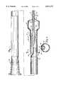
- FIG. 1is a sectional view of a first preferred embodiment of the balloon catheter of the present invention.
- FIG. 2is a sectional view along section 2--2 of FIG. 1.
- FIG. 3is a sectional view of a second preferred embodiment of the balloon catheter of the present invention.
- FIG. 4is a sectional view along section 4-4 of FIG. 3.
- FIG. 5is a detail view showing a brazed bond between the tube and core shown in FIG. 4.
- FIG. 6is a sectional view of a third preferred embodiment of the balloon catheter of the present invention.
- FIG. 7is an enlarged sectional view of a distal portion of the third preferred embodiment.
- FIG. 8is a sectional view along section 8--8 of FIG. 7.
- Catheter 10 shown in FIGS. 1 and 2is a dilatation balloon catheter which includes main catheter tube or shaft 12, balloon member 14, core member 16, and spring tip 18.
- Tube 12is an elongated flexible thin walled metal tube, preferably of stainless steel or of stainless steel with a low friction coating such as polytetrafluoroethylene.
- Luer fitting 20is mounted at the proximal end of tube 12 for connection to an inflation device (not shown) which provides fluid under pressure through the interior lumen of tube 12 for balloon inflation.
- tube 12At its distal end, tube 12 has a section 22 of reduced outside diameter and a formed recess 24 in which the proximal end of core member 16 is attached, preferably by brazing.
- Balloon member 14which is preferably a polymer material such as a polyolefin, has a proximal or waist segment 26, a distensible balloon segment 28, and a small diameter distal segment 30. Proximal segment 26 is bonded to the distal end of tube 12 and to core member 16. An adhesive and sealing material 32 (such as an epoxy) is provided to seal together tube 12 and core member 16 with the proximal segment 26 of balloon member 14.
- core member 16is generally aligned parallel with tube 12 and balloon member 14 and is coaxially aligned except for its proximal end.
- Core member 16has a proximal section 34 of larger outer diameter and a distal section 36 of smaller outer diameter.
- Central vent passage 38extends essentially the entire length of core member 16, and opens to the exterior of catheter 10 at the proximal end of core member 16.
- Vent opening 40provides communication between vent passage 38 and the interior of balloon member 14 to allow for the positive pressure purging of air out through vent opening 40, vent passage 38, and the open proximal end of core member 16.
- Distal segment 30 of balloon member 14is bonded (such as by an epoxy) to the distal end of core segment 36.
- core segment 36extends out slightly beyond the end of distal segment 30, and spring tip 18 is attached to core segment 36, such as by brazing or soldering.
- Spring tip 18includes a solid core segment 42 (which blocks the distal end of vent passage 38), coiled spring 44, and brazed safety button 46. The more proximally located portions of spring 44 are preferably bonded or otherwise attached to the outer end of distal core segment 36.
- Distensible segment 28 of balloon member 14has (by special shaping, wall thickness, or material treatment) a greater tendency to expand under fluid pressure than waist segment 26.
- catheter 10is shown in a condition in which distensible balloon segment 28 is inflated.
- catheter 10Before being inserted into the patient, catheter 10 is connected to an inflation device (not shown) and liquid is supplied under pressure through the interior of tube 12 to the interior of balloon member 14. This liquid purges air contained within the interior of catheter 10 out through vent opening 40 and vent passage 38 to the exterior of catheter 10. Vent opening 40 and passage 38 are sized so that fluid pressure can be supplied to inflate balloon segment 28 without significant leaking of the inflation liquid, and so that air and a small plug of liquid will enter passage 38.
- the inflation deviceis then used to draw the liquid back so as to collapse balloon segment 28 around core member 16. This provides a low profile while catheter 10 is being inserted into the patient.
- the plug of liquid within vent passage 38blocks air from re-entering the interior of balloon segment 28.
- the advance of the contrast liquid into passage 38is controlled by two factors. First, the liquid column is forced through the vent opening 40 by pressure applied to the liquid, and liquid flow is resisted to an extent by the small diameter (about 0.001 to about 0.003 inch) of vent opening 40. Second, once the liquid has entered the passage 38, capillary action which is governed by the surface tension between the liquid and the surface characteristics and diameter of passage 38 will allow the liquid into the core along a certain length until a state of equilibrium is reached. At this point, more pressure would be required to begin movement of the liquid in the column than catheter 10 can be subject to, and therefore the liquid advances no further. This applies to both the application of positive pressure and vacuum.
- catheter 10is not only ventable through vent opening 40 and passage 38, but is also self-sealing. No additional seal or valve is required to prevent liquid and pressure from bleeding off through this vent passage.
- the flow characteristics of the radiopaque liquid in the coreare dependent on optimization of the capillary action and static breakaway pressure shears.
- Catheter 10is then inserted into the patient and its distal end is advanced through the patient's vascular system to the location of the stenosis which is to be treated.
- a significant advantage of the present inventionis the improved "steerability", “pushability” and “torqueability” (i.e., torque transfer) characteristics which are provided by tube 12.
- the thin walled metal tube 12 used in catheter 10 of the present inventionprovides sufficient flexibility to traverse bends, while having improved pushability and improved torque transmitting characteristics.
- FIGS. 3 and 4show dilatation catheter 50, which is another embodiment of the present invention.
- Catheter 50includes metal tube 52, balloon member 54, core member 56, spring tip 58 and luer fitting 60.
- Tube 52is an elongated flexible thin walled metal tube of a material such as 304 stainless steel.
- Tube 52preferably has a low coefficient of friction coating, such as polytetrafluoroethylene.
- metal tube 52has a length of about 43 inches, an inside diameter of about 0.020 inch and an outside diameter of about 0.024 inch.
- luer fitting 60At the proximal end of metal tube 52 is luer fitting 60.
- An inflation device(not shown) is connected to fitting 60 for balloon inflation/deflation.
- Balloon member 54is mounted at the distal end of metal tube 52, and is preferably an axially stretchable thermoplastic balloon material which has the ability to have small inside diameter and outside diameter dimensions and a thin wall, while still maintaining an acceptably high burst rating (for example, ten to twelve atmospheres) and a compliance comparable to other balloons used in angioplasty dilatation catheters.
- Balloon member 54has a proximal or waist segment 62, a distensible balloon segment 64 and a distal segment 66. Balloon segment 64 is shown in FIG. 3 in its fully inflated condition.
- proximal waist segment 62has a length of about 12 inches, an outside diameter of about 0.034 inch and a wall thickness of about 0.0045 inch.
- the proximal end of waist segment 62overlaps and is bonded by epoxy bond 68 to the distal end of metal tube 52 and to a portion of core member 56.
- Proximal end 70 of waist segment 62is beveled to provide a smooth profile as catheter 50 is withdrawn from the patient.
- the wall thickness of balloon segment 64has a wall thickness which varies from about 0.0045 inch at the end which joins waist segment 62, to a minimum thickness of about 0.001 to about 0.003 inch in central section 64A, (depending on balloon outside diameter) to a wall thickness of about 0.004 inch at the end which joins to distal segment 66.
- Central segment 64Ais about 0.8 inch in length.
- Distal segment 66is bonded by an epoxy bond 72 to spring tip coil 58, which in turn is attached by braze joint 73 to core member 56.
- the outside diameter of distal segment 66is about 0.022 inch and the inside diameter is about 0.014 inch.
- spring tip coil 58has an outside diameter of about 0.011 inch to about 0.012 inch, and has a similar or slightly larger outside diameter distal to the bonding region.
- the diameter of the coil wire forming spring tip coil 58is about 0.003 inch.
- Spring tip coil 58extends about 0.8 inch beyond the distal segment 66, and is connected to the distal end of core 56 by a braze bond or safety button 74.
- core member 56includes vent tube core 76 and solid distal core 78, which are connected together in end-to-end fashion by braze joint and marker 80.
- Vent tube core 76has four sections 76A-76D of differing outside diameters.
- segment 76Ahas an outside diameter of about 0.012 inch
- segment 76Bhas an outside diameter of about 0.009 inch
- segment 76Chas an outside diameter of about 0.007 inch
- segment 76Dhas an outside diameter of about 0.006 inch.
- This transition of decreasing outside diameter in the direction toward the distal endtakes advantage of typical curvature of anatomy that catheter 50 will experience in the human body.
- segment 76Bhas a length of about 4.5 inches and is flexible enough to pass through the aortic arch when the balloon segment 64 is trying to cross the lesion.
- Segment 76C of vent tube core 76is preferably about 6 inches in length and is more flexible in order to negotiate the coronary arteries which are typically more tortuous than the aortic arch.
- vent passageway 82Extending through vent tube core 76 is vent passageway 82, which opens to the interior of balloon segment 64 near the proximal end through vent opening 84 and opens to the exterior of catheter 50 through opening 86.
- Plug 87blocks the proximal end of vent passage 82 so that pressurized fluid from the interior of metal tube 52 cannot directly enter the proximal end passage 82 and flow out through opening 86.
- segment 76A of vent tube core 76is positioned in slot 88 which is formed in the distal end of metal tube 52.
- slot 88is about 0.011 inch wide (which is slightly narrower than the outside diameter of segment 76A) and is about 0.025 inch long.
- Slot 88is preferably formed by electrodischarge machining, and segment 76A is brazed in position in slot 88 so that a seal is formed between segment 76A and tube 52.
- vent tube core 76This preferred bonding of vent tube core 76 to metal tube 52 has the advantage that tube 52 and core 76 maintain good straightness with respect to one other (which is critical for torqueability requirements to prevent whipping of the distal end of catheter 52 as torque is applied to tube 52).
- the flow lumenis not as restricted as it would be without the presence of slot 88.
- both the surfaces of vent tube core 76 and metal tube 52are exposed during processing, the weld can be more reliably made.
- vent core tube 76from an off-axis connection to tube 52 to a generally coaxial position in more distal portions is much more gradual than shown.
- Solid distal core 78has a segment 78A which has the same outside diameter (0.006 inch) as segment 76D, a segment 78B having an outside diameter of 0.004 inch, and a flat ribbon segment 78C within spring tip 58 which is about 0.001 inch thick and about 0.003 inch wide.
- vent tube core 76 and solid distal core 78are made of the same material, which is preferably a high strength stainless steel or other high strength alloy. 17-7 PH stainless, 18-8 PH stainless or 400 Series heat treatable stainless steel are examples of such high strength materials.
- the high strength characteristics of vent tube core 76 and solid distal core 78reduces the chances of them taking on a permanent set when forced through a typical tortuous human anatomy.
- core member 56is a single solid core member.
- the vent passageway shown in FIG. 3is not used, and core member 56 can be formed from a single solid wire core and then machined to the desired dimensions.
- this alternative embodiment of FIG. 5is that generally a solid wire has somewhat greater strength and hardness than a tube of the same outside diameter.
- core member 56is an integral member, a bond between two sections of the core member is not required.
- a conventional vacuum purgecan be used.
- FIGS. 6, 7 and 8show dilatation catheter 100, which is another embodiment of the present invention.
- Catheter 100includes manifold 102, metal tube 104, core 106, waist tube 108, balloon member 110 and spring tip 112.
- Manifold 102has a luer fitting 114 at its proximal end, for connection to an inflation device (not shown) which provides fluid under pressure to catheter 100.
- Lure fitting 114is connected to a first end cap 116, which in turn is connected to a manifold body 118.
- Manifold body 118has a reduced distal end portion 120, onto which is threadably mounted a second end cap 122. Retained between second end cap 122 and distal end portion 120 are an annual compression sleeve 124 and a manifold washer 126.
- Distal end portion 120 of manifold body 118, sleeve 124, washer 126 and second end cap 122all have central longitudinal openings therethrough for reception of a strain relief tube 128, as seen in FIG. 6.
- strain relief tube 128,Received within strain relief tube 128, (which is preferably formed from a polyolefin copolymer material and adhered to tube 104) is a proximal end portion of metal tube 104, with that proximal end portion extending proximally through distal end portion 120 of manifold body 118 and into an internal cavity 130 in manifold body 118.
- One or more inserts 132are also in cavity 130, to take up the space therein and reduce the need for inflation fluid in the catheter 100.
- First end cap 116also has a central opening therethrough, to permit inflation fluid to flow between the luer fitting 114 and cavity 130.
- luer fitting 114 and first end cap 116are secured together by an adhesive material, as are first end cap 116 and manifold body 118.
- second end cap 122is preferably secured by an adhesive to distal end portion 120 of manifold body 118, in addition to the threaded engagement thereof. Tightening of the second end cap 122 onto distal end portion 120 of manifold body 118 compresses sleeve 124 to create a seal about strain relief tube 128.
- Tube 104is an elongated flexible thin walled metal tube, preferably a stainless hypotube with a low friction coating such as polytetrafluoroethylene.
- metal tube 104has a length of about 44 inches, an inside diameter of about 0.017 inch, and an outside diameter of about 0.024 inch (1.8 French).
- tube 104has a longitudinal slot 150 formed therein.
- slot 150is about 0.011 inch wide, is about 0.25 inch long.
- Core 106is an elongated member which is preferably formed from a high-strength stainless steel or other high-strength alloy, and which is connected to tube 104 at a first bonding region 152. 17-7 PH stainless, 18-8 PH stainless, and 300 or 400 series stainless steel are examples of such high-strength materials.
- the high strength characteristics of core 106reduces the chances of it taking on a permanent set when forced through a typically tortuous human anatomy.
- a proximal end 154 of core 106is received within slot 150 and brazed or soldered thereto to securely fasten core 106 to tube 104 to define first bonding region 152.
- core 106is a single solid core wire, which is reduced in cross-section by elongated tapers or stepped reductions (e.g., taper 155) as it extends distally from tube 104. This reduction in cross-section further enhances the flexibility of core 106 as it extends distally, and through balloon 110.
- This preferred bonding of core 106 to metal tube 104has the advantage that tube 104 and core 106 maintain good straightness with respect to one another (which is critical for torqueability requirements in order to prevent whipping of the distal end of the catheter 100 as torque is applied to tube 104).
- proximal end 154 of core 106is offset from the axis of catheter 100, but assumes a central axial alignment distally of tube 104, as it extends through waist tube 108 and balloon 110.
- the drawings hereinare not to scale. In FIG. 7, for example, the transition of core 106 from an off-axis connection (to tube 104) to a generally coaxial position distally therefrom is more gradual than shown.
- core 106may have an outside diameter of about 0.012 inch, reducing in size distally (for increased distal flexibility) until it is received within spring tip 112.
- core 106may be formed as a thin, flat ribbon segment within spring tip 112, which is then secured to spring tip 112 at the distal end thereof by a welded safety button 156.
- radiopaque markers 157are secured to core 106 and spring tip 112 is formed from radiopaque material (such as a platinum alloy) to aid in locating catheter 100 in the patient's vascular system by fluoroscopy.
- Waist tube 108is an elongated flexible tube, also mounted to tube 104 as seen in FIG. 7, and is preferably formed from a polymer material such a high density polyethylene (which is a relatively lubricious, flexible and high strength material).
- a proximal end 158 of waist tube 108extends proximally over distal end 145 of tube 104.
- Proximal end 158 of waist tube 108is secured concentrically about tube 104 by a suitable adhesive 159 (such as cyanoacrylate), at a second bonding region 160 proximally spaced from first bonding region 152 between tube 104 and core 106.
- suitable adhesive 159such as cyanoacrylate
- Waist tube 108extends distally about core 106 from tube 104. At its proximal end 158, waist tube 108 has an outer diameter of about 0.031 inch, and tapers down to an outer diameter of about 0.026 inch distally therefrom. In this reduced distal section, the inner diameter of waist tube 108 is about 0.021 inch, and this reduced section is about 11.10 inches long. Preferably, the wall thickness of waist tube 108 is about 0.0025 inch.
- the reduction in diameters of waist tube 108 (and accordingly, catheter 100)allows better flexibility and "trackability" for catheter 100 in the patient's vascular system. By injecting radiopaque dyes therein, the patient's arterial lumens are made visible on a fluoroscope. Reducing the diameter of catheter 100 allows more dye to flow adjacent and around catheter 100, thus making the lumen areas more visible which further aids in the positioning of catheter 100 in the artery and evaluation of dilatation performance.
- first bonding region 152By mounting proximal end 158 of waist tube 108 to tube 104 proximally of first bonding region 152 between tube 104 and core 106, a smoother external surface transition is presented and made between components of catheter 100 adjacent distal end 145 of tube 104. Further, there are no material discontinuities or bumps adjacent first bonding region 152 external of catheter 100. This arrangement also provides a more uniform bond structure (annular with no obstructions) for securing waist tube 108 to tube 104 than might otherwise be possible (see, e.g., FIG. 8).
- waist tube 108is connected to a proximal balloon segment or waist 162 of balloon 110, using a suitable adhesive and sealing material 163 (such as an epoxy) thereby defining a third bonding region 163A.
- balloon 110is preferably formed from an axially-stretchable thermoplastic balloon material which has the ability to have small inside diameter and outside diameter dimensions, and a thin wall, while still maintaining an acceptably high burst rating (for example, 10 to 12 atmospheres) and a compliance comparable to other balloons used in angioplasty dilatation catheters.
- this balloon materialis formed from a polymer material such as polyolefin copolymer.
- Balloon 110has a distensible balloon segment 164 (shown in FIG. 7 in its fully inflated condition) and a distal balloon segment or waist 166.
- proximal waist 162has a length of about 0.50 inch, an outer diameter of about 0.031 inch and a wall thickness of about 0.005 inch.
- the wall thickness of distensible balloon segment 164varies from about 0.005 inch at the end which joins waist 162, to a minimum thickness of about 0.0018 inch to about 0.0025 inch in central section 164A (depending upon balloon outside diameter) to a wall thickness of about 0.005 inch at the end which joins to distal waist 166.
- Central segment 64Ais about 0.80 inch in length.
- Distal waist 166 of balloon 110is bonded by an adhesive bond 168 (such as cyanoacrylate) to spring tip 112 (thereby defining a fourth bonding region 168A), which is in turn attached by weld joint 156 to core 106.
- the outer diameter of distal waist 166is about 0.021 inch to 0.029 inch (depending upon balloon outside diameter) and the inner diameter is about 0.016 inch.
- spring tip 112has an outer diameter of about 0.014 inch.
- the diameter of the coil wire which is helically wound to form spring tip 112is about 0.003 inch.
- Spring tip 112extends about 0.89 inch beyond distal waist 166 of balloon 110. Although not shown in FIG. 7, spring tip 112 is also connected to core 106 proximally of joint 156 by a brazed or soldered bond within fourth bonding region 168A, as illustrated for the similar catheter spring tip structure seen in FIG. 3.
- a vent tube 175is disposed within balloon 110.
- Vent tube 175has a proximal end 177 and a distal end 179. At its distal end 179, vent tube 175 is flattened and secured within epoxy bond material 168 of fourth bonding region 168A. Vent tube 175 extends proximally therefrom through the interior of balloon 110 and has its proximal end 177 secured within epoxy bond 163 of third bonding region 163A between waist tube 108 and proximal waist 162 of balloon 110. At its proximal end 177, vent tube 175 has an outlet 181 which is open to the exterior of catheter 100.
- vent tube 175Adjacent its distal end 179 and within the interior of balloon 110, vent tube 175 has one or more inlets 183 to facilitate the passage of gases from the interior of balloon 110 into vent tube 175 and to outlet 181.
- vent tube 175has an outer diameter of about 0.003 inch and an inner diameter (vent lumen) of about 0.002 inch, and is made of material such as polyimide.
- catheter 100Prior to use in a patient, catheter 100 is connected to an inflation device (not shown) through luer fitting 114 and inflation fluid (typically, a 50/50 solution of radiopaque dye and saline) is supplied under pressure through the interior of tube 104 and waist tube 108 to the interior of balloon member 110.
- inflation fluidtypically, a 50/50 solution of radiopaque dye and saline
- This fluidpressurizes balloon 110 and purges air contained within the interior of catheter 100 out through inlet 183 of vent tube 175 and through tube 175 to the catheterts exterior via outlet 181.
- Vent tube 175 and its openingsare sized such that fluid pressure can be supplied to inflate balloon 110 without significant leaking of inflation fluid, and so that air and a small plug of fluid will enter vent tube 175.
- the inflation deviceWhen the air has been purged from the interior of catheter 100, the inflation device is then used to draw the fluid back so as to depressurize catheter 100 and collapse balloon 110 around core 106 (waist tube 108 does not collapse, however, because it is formed from a high strength material). This provides a low profile for balloon 110 while catheter 100 is being inserted into the patient's vascular system. The plug of liquid within vent tube 175, however, blocks air from re-entering the interior of balloon 110.
- vent tube 175The advance of inflation fluid into vent tube 175 is controlled by the same factors as discussed above with respect to the advance of contrast liquid into passage 38 in the embodiment illustrated in FIGS. 1 and 2. Again, this applies both during the application of positive pressure and vacuum. Accordingly, catheter 100 is not only ventable through vent 175, but also self-sealing in that no additional seal or valve is required to prevent inflation fluid and pressure from bleeding off vent tube 175.
- catheter 100is used by inserting it into the patient's vascular system until its distal end is advanced to the location of the stenosis to be treated.
- the use of a thin-walled metal tuberesults in significant advantages in steerability, pushability and torqueability characteristics for catheter 100.
- Thin-walled metal tube 104provides sufficient flexibility through traverse bends in the vascular system, yet has pushability and torque transmitting characteristics not found in prior art fixed wire catheters.
- the use of a hypotube for the relatively long proximal section of the catheter tubeprovides a tube with a smaller outer diameter, thereby providing enhanced trackability during the angioplasty procedure.
- the present inventionis an improved angioplasty dilatation balloon catheter of the "non-over-the-wire" type. In other words, it does not require a guide wire which passes through its entire length. With the present invention, a very low shaft diameter can be achieved without sacrificing pushability or torque transfer characteristics.
Landscapes
- Health & Medical Sciences (AREA)
- Life Sciences & Earth Sciences (AREA)
- Heart & Thoracic Surgery (AREA)
- Hematology (AREA)
- Engineering & Computer Science (AREA)
- Anesthesiology (AREA)
- Biomedical Technology (AREA)
- Pulmonology (AREA)
- Biophysics (AREA)
- Animal Behavior & Ethology (AREA)
- General Health & Medical Sciences (AREA)
- Public Health (AREA)
- Veterinary Medicine (AREA)
- Vascular Medicine (AREA)
- Child & Adolescent Psychology (AREA)
- Media Introduction/Drainage Providing Device (AREA)
Abstract
Description
Claims (18)
Priority Applications (2)
| Application Number | Priority Date | Filing Date | Title |
|---|---|---|---|
| US07/782,242US6071273A (en) | 1988-02-29 | 1991-10-23 | Fixed wire dilatation balloon catheter |
| US08/473,477US5567203A (en) | 1988-02-29 | 1995-06-07 | Balloon dilatation catheter with proximal hypotube |
Applications Claiming Priority (3)
| Application Number | Priority Date | Filing Date | Title |
|---|---|---|---|
| US07/162,004US4943278A (en) | 1988-02-29 | 1988-02-29 | Dilatation balloon catheter |
| US43371189A | 1989-11-13 | 1989-11-13 | |
| US07/782,242US6071273A (en) | 1988-02-29 | 1991-10-23 | Fixed wire dilatation balloon catheter |
Related Parent Applications (1)
| Application Number | Title | Priority Date | Filing Date |
|---|---|---|---|
| US43371189AContinuation | 1988-02-29 | 1989-11-13 |
Related Child Applications (1)
| Application Number | Title | Priority Date | Filing Date |
|---|---|---|---|
| US08/473,477ContinuationUS5567203A (en) | 1988-02-29 | 1995-06-07 | Balloon dilatation catheter with proximal hypotube |
Publications (1)
| Publication Number | Publication Date |
|---|---|
| US6071273Atrue US6071273A (en) | 2000-06-06 |
Family
ID=26858365
Family Applications (4)
| Application Number | Title | Priority Date | Filing Date |
|---|---|---|---|
| US07/782,242Expired - LifetimeUS6071273A (en) | 1988-02-29 | 1991-10-23 | Fixed wire dilatation balloon catheter |
| US07/796,901Expired - LifetimeUS5702364A (en) | 1988-02-29 | 1991-11-22 | Fixed-wire dilatation balloon catheter |
| US07/806,588Expired - LifetimeUS5387225A (en) | 1988-02-29 | 1991-12-12 | Dilatation catheter with transition member |
| US08/473,477Expired - LifetimeUS5567203A (en) | 1988-02-29 | 1995-06-07 | Balloon dilatation catheter with proximal hypotube |
Family Applications After (3)
| Application Number | Title | Priority Date | Filing Date |
|---|---|---|---|
| US07/796,901Expired - LifetimeUS5702364A (en) | 1988-02-29 | 1991-11-22 | Fixed-wire dilatation balloon catheter |
| US07/806,588Expired - LifetimeUS5387225A (en) | 1988-02-29 | 1991-12-12 | Dilatation catheter with transition member |
| US08/473,477Expired - LifetimeUS5567203A (en) | 1988-02-29 | 1995-06-07 | Balloon dilatation catheter with proximal hypotube |
Country Status (1)
| Country | Link |
|---|---|
| US (4) | US6071273A (en) |
Cited By (49)
| Publication number | Priority date | Publication date | Assignee | Title |
|---|---|---|---|---|
| US6585719B2 (en)* | 2001-01-04 | 2003-07-01 | Scimed Life Systems, Inc. | Low profile metal/polymer tubes |
| US20040054323A1 (en)* | 2001-11-01 | 2004-03-18 | Wantink Kenneth L. | Catheter having improved rapid exchange junction |
| US6786887B2 (en) | 2001-01-26 | 2004-09-07 | Scimed Life Systems, Inc. | Intravascular occlusion balloon catheter |
| US20050059890A1 (en)* | 2003-07-31 | 2005-03-17 | Wislon-Cook Medical Inc. | System and method for introducing multiple medical devices |
| US20050070879A1 (en)* | 2003-09-26 | 2005-03-31 | Medtronic Vascular, Inc | Transition section for a catheter |
| US20050070881A1 (en)* | 2003-09-26 | 2005-03-31 | Richard Gribbons | Transition section for a catheter |
| US20050137622A1 (en)* | 2003-12-23 | 2005-06-23 | Scimed Life Systems, Inc. | Catheter with distal occlusion |
| US20050143770A1 (en)* | 2003-07-31 | 2005-06-30 | Carter Matthew P. | Distal wire stop |
| US20050197669A1 (en)* | 2004-03-03 | 2005-09-08 | Conor Medsystems, Inc. | Rapid exchange balloon catheter with braided shaft |
| US20050197667A1 (en)* | 2004-03-02 | 2005-09-08 | Scimed Life Systems, Inc. | Occlusion balloon catheter with external inflation lumen |
| US20050267442A1 (en)* | 2004-05-27 | 2005-12-01 | Randolf Von Oepen | Catheter having main body portion with coil-defined guidewire passage |
| US20050267408A1 (en)* | 2004-05-27 | 2005-12-01 | Axel Grandt | Catheter having first and second guidewire tubes and overlapping stiffening members |
| US20060030864A1 (en)* | 2003-07-31 | 2006-02-09 | Wilson-Cook Medical Inc. | Catheter with splittable wall shaft and peel tool |
| US20060071371A1 (en)* | 2004-09-29 | 2006-04-06 | Abbott Laboratories Vascular Enterprises Ltd. | Method for connecting a catheter balloon with a catheter shaft of a balloon catheter |
| US20060184112A1 (en)* | 2005-02-17 | 2006-08-17 | Horn Daniel J | Medical devices |
| US20070016165A1 (en)* | 2004-05-27 | 2007-01-18 | Randolf Von Oepen | Catheter having plurality of stiffening members |
| US20070016132A1 (en)* | 2004-05-27 | 2007-01-18 | Oepen Randolf V | Catheter having plurality of stiffening members |
| US20070021771A1 (en)* | 2004-05-27 | 2007-01-25 | Oepen Randolf V | Catheter having plurality of stiffening members |
| US20070060910A1 (en)* | 2004-05-27 | 2007-03-15 | Axel Grandt | Multiple lumen catheter and method of making same |
| US20070078439A1 (en)* | 2004-05-27 | 2007-04-05 | Axel Grandt | Multiple lumen catheter and method of making same |
| US20070083188A1 (en)* | 2004-05-27 | 2007-04-12 | Axel Grandt | Catheter having overlapping stiffening members |
| US20070112422A1 (en)* | 2005-11-16 | 2007-05-17 | Mark Dehdashtian | Transapical heart valve delivery system and method |
| US20090005754A1 (en)* | 2007-06-29 | 2009-01-01 | Wilson-Cook Medical Inc. | Distal wire stop having adjustable handle |
| US20090216185A1 (en)* | 2008-02-26 | 2009-08-27 | Boston Scientific Scimed, Inc. | Balloon catheter with durable tip portion |
| US20110015728A1 (en)* | 2009-07-14 | 2011-01-20 | Edwards Lifesciences Corporation | Transapical delivery system for heart valves |
| US20110238166A1 (en)* | 2000-09-12 | 2011-09-29 | Shlomo Gabbay | Method for direct implantation of a heart valve prosthesis |
| US8157766B2 (en) | 2005-09-01 | 2012-04-17 | Medrad, Inc. | Torqueable kink-resistant guidewire |
| US8323432B2 (en) | 2002-12-31 | 2012-12-04 | Abbott Laboratories Vascular Enterprises Limited | Catheter and method of manufacturing same |
| US9055937B2 (en) | 2011-04-01 | 2015-06-16 | Edwards Lifesciences Corporation | Apical puncture access and closure system |
| WO2015123313A1 (en)* | 2014-02-11 | 2015-08-20 | Cornell University | Method and apparatus for manipulating the side wall of a body lumen or body cavity so as to provide increased visualization of the same and/or increased access to the same, and/or for stabilizing instruments relative to the same |
| US9226824B2 (en) | 2010-11-30 | 2016-01-05 | Edwards Lifesciences Corporation | Surgical stabilizer and closure system |
| US9381082B2 (en) | 2011-04-22 | 2016-07-05 | Edwards Lifesciences Corporation | Devices, systems and methods for accurate positioning of a prosthetic valve |
| US9687345B2 (en) | 2014-05-29 | 2017-06-27 | Edwards Lifesciences Cardiaq Llc | Prosthesis, delivery device and methods of use |
| US9764067B2 (en) | 2013-03-15 | 2017-09-19 | Boston Scientific Scimed, Inc. | Superhydrophobic coating for airway mucus plugging prevention |
| US9924853B2 (en) | 2009-12-15 | 2018-03-27 | Cornell University | Method and apparatus for stabilizing, straightening, expanding and/or flattening the side wall of a body lumen and/or body cavity so as to provide increased visualization of the same and/or increased access to the same, and/or for stabilizing instruments relative to the same |
| US9986893B2 (en) | 2009-12-15 | 2018-06-05 | Cornell University | Method and apparatus for manipulating the side wall of a body lumen or body cavity so as to provide increased visualization of the same and/or increased access to the same, and/or for stabilizing instruments relative to the same |
| US10149757B2 (en) | 2013-03-15 | 2018-12-11 | Edwards Lifesciences Corporation | System and method for transaortic delivery of a prosthetic heart valve |
| US10149601B2 (en) | 2009-12-15 | 2018-12-11 | Lumendi Ltd. | Method and apparatus for manipulating the side wall of a body lumen or body cavity so as to provide increased visualization of the same and/or increased access to the same, and/or for stabilizing instruments relative to the same |
| USRE47379E1 (en) | 2006-05-03 | 2019-05-07 | Teleflex Innovations S.A.R.L. | Coaxial guide catheter for interventional cardiology procedures |
| US10485401B2 (en) | 2009-12-15 | 2019-11-26 | Lumendi Ltd. | Method and apparatus for manipulating the side wall of a body lumen or body cavity so as to provide increased visualization of the same and/or increased access to the same, and/or for stabilizing instruments relative to the same |
| US10751514B2 (en) | 2016-12-09 | 2020-08-25 | Teleflex Life Sciences Limited | Guide extension catheter |
| US10946177B2 (en) | 2018-12-19 | 2021-03-16 | Teleflex Life Sciences Limited | Guide extension catheter |
| US10953197B2 (en) | 2019-01-07 | 2021-03-23 | Teleflex Life Sciences Limited | Guide extension catheter |
| US10974028B2 (en) | 2015-05-26 | 2021-04-13 | Teleflex Life Sciences Limited | Guidewire fixation |
| US11524142B2 (en) | 2018-11-27 | 2022-12-13 | Teleflex Life Sciences Limited | Guide extension catheter |
| US11877722B2 (en) | 2009-12-15 | 2024-01-23 | Cornell University | Method and apparatus for manipulating the side wall of a body lumen or body cavity |
| US11986150B2 (en) | 2009-12-15 | 2024-05-21 | Lumendi Ltd. | Method and apparatus for manipulating the side wall of a body lumen or body cavity so as to provide increased visualization of the same and/or increased access to the same, and/or for stabilizing instruments relative to the same |
| US12022998B2 (en) | 2020-11-16 | 2024-07-02 | Lumendi Ltd. | Methods and apparatus for inverting a hollow sleeve and thereafter reverting an inverted hollow sleeve |
| US12121209B2 (en) | 2014-02-11 | 2024-10-22 | Cornell University | Method and apparatus for providing increased visualization and manipulation of a body side wall |
Families Citing this family (126)
| Publication number | Priority date | Publication date | Assignee | Title |
|---|---|---|---|---|
| US5454788A (en)* | 1991-04-24 | 1995-10-03 | Baxter International Inc. | Exchangeable integrated-wire balloon catheter |
| US5571087A (en)* | 1992-02-10 | 1996-11-05 | Scimed Life Systems, Inc. | Intravascular catheter with distal tip guide wire lumen |
| WO1994004216A1 (en) | 1992-08-25 | 1994-03-03 | Bard Connaught | Dilatation catheter with stiffening wire |
| US5500180A (en)* | 1992-09-30 | 1996-03-19 | C. R. Bard, Inc. | Method of making a distensible dilatation balloon using a block copolymer |
| US5549580A (en)* | 1995-01-23 | 1996-08-27 | Cordis Corporation | Catheter having a flexible distal tip and method of manufacturing |
| US5749851A (en) | 1995-03-02 | 1998-05-12 | Scimed Life Systems, Inc. | Stent installation method using balloon catheter having stepped compliance curve |
| US6235007B1 (en)* | 1995-11-27 | 2001-05-22 | Therox, Inc. | Atraumatic fluid delivery devices |
| US6068623A (en) | 1997-03-06 | 2000-05-30 | Percusurge, Inc. | Hollow medical wires and methods of constructing same |
| US6022336A (en) | 1996-05-20 | 2000-02-08 | Percusurge, Inc. | Catheter system for emboli containment |
| CA2209366C (en)* | 1996-09-13 | 2004-11-02 | Interventional Technologies, Inc. | Incisor-dilator with tapered balloon |
| US5810869A (en)* | 1996-11-18 | 1998-09-22 | Localmed, Inc. | Methods for loading coaxial catheters |
| US5690613A (en)* | 1996-12-06 | 1997-11-25 | Medtronic, Inc. | Rapid exchange high pressure transition for high pressure catheter with non-compliant balloon |
| US6355016B1 (en) | 1997-03-06 | 2002-03-12 | Medtronic Percusurge, Inc. | Catheter core wire |
| US6190332B1 (en) | 1998-02-19 | 2001-02-20 | Percusurge, Inc. | Core wire with shapeable tip |
| US5830183A (en) | 1997-06-30 | 1998-11-03 | Schneider (Usa) Inc | Clip device for vascular catheter |
| US6371943B1 (en) | 1997-09-08 | 2002-04-16 | Epimed International, Inc. | Spring tip needle combination |
| US6099926A (en)* | 1997-12-12 | 2000-08-08 | Intella Interventional Systems, Inc. | Aliphatic polyketone compositions and medical devices |
| US6093463A (en)* | 1997-12-12 | 2000-07-25 | Intella Interventional Systems, Inc. | Medical devices made from improved polymer blends |
| US6228072B1 (en) | 1998-02-19 | 2001-05-08 | Percusurge, Inc. | Shaft for medical catheters |
| US6120522A (en)* | 1998-08-27 | 2000-09-19 | Scimed Life Systems, Inc. | Self-expanding stent delivery catheter |
| US6139524A (en)* | 1998-10-16 | 2000-10-31 | Scimed Life Systems, Inc. | Stent delivery system with perfusion |
| US6102890A (en) | 1998-10-23 | 2000-08-15 | Scimed Life Systems, Inc. | Catheter having improved proximal shaft design |
| US6059813A (en)* | 1998-11-06 | 2000-05-09 | Scimed Life Systems, Inc. | Rolling membrane stent delivery system |
| US6544278B1 (en)* | 1998-11-06 | 2003-04-08 | Scimed Life Systems, Inc. | Rolling membrane stent delivery system |
| US6254609B1 (en) | 1999-01-11 | 2001-07-03 | Scimed Life Systems, Inc. | Self-expanding stent delivery system with two sheaths |
| US6458867B1 (en) | 1999-09-28 | 2002-10-01 | Scimed Life Systems, Inc. | Hydrophilic lubricant coatings for medical devices |
| US6299595B1 (en) | 1999-12-17 | 2001-10-09 | Advanced Cardiovascular Systems, Inc. | Catheters having rapid-exchange and over-the-wire operating modes |
| US6589207B1 (en)† | 1999-12-21 | 2003-07-08 | Advanced Cardiovascular Systems, Inc. | Rapid exchange catheter having a support mandrel |
| US6702843B1 (en) | 2000-04-12 | 2004-03-09 | Scimed Life Systems, Inc. | Stent delivery means with balloon retraction means |
| US6364894B1 (en)* | 2000-06-12 | 2002-04-02 | Cordis Corporation | Method of making an angioplasty balloon catheter |
| US6663648B1 (en) | 2000-06-15 | 2003-12-16 | Cordis Corporation | Balloon catheter with floating stiffener, and procedure |
| US7008535B1 (en) | 2000-08-04 | 2006-03-07 | Wayne State University | Apparatus for oxygenating wastewater |
| US6527732B1 (en) | 2000-10-17 | 2003-03-04 | Micro Therapeutics, Inc. | Torsionally compensated guidewire |
| US6656211B1 (en) | 2000-10-26 | 2003-12-02 | Scimed Life Systems, Inc. | Stent delivery system with improved tracking |
| US6736839B2 (en)* | 2001-02-01 | 2004-05-18 | Charles Cummings | Medical device delivery system |
| US6645238B2 (en) | 2001-07-09 | 2003-11-11 | Scimed Life Systems, Inc. | Skids stent delivery system |
| US6679909B2 (en)* | 2001-07-31 | 2004-01-20 | Advanced Cardiovascular Systems, Inc. | Rapid exchange delivery system for self-expanding stent |
| US7004963B2 (en) | 2001-09-14 | 2006-02-28 | Scimed Life Systems, Inc. | Conformable balloons |
| US10258340B2 (en)* | 2001-11-09 | 2019-04-16 | DePuy Synthes Products, Inc. | Reloadable sheath for catheter system for deploying vasoocclusive devices |
| US6716223B2 (en) | 2001-11-09 | 2004-04-06 | Micrus Corporation | Reloadable sheath for catheter system for deploying vasoocclusive devices |
| US7300534B2 (en)* | 2002-01-15 | 2007-11-27 | Boston Scientific Scimed, Inc. | Bonds between metals and polymers for medical devices |
| US7112357B2 (en) | 2002-01-23 | 2006-09-26 | Boston Scientific Scimed, Inc. | Medical devices comprising a multilayer construction |
| US7785340B2 (en)* | 2002-02-04 | 2010-08-31 | Boston Scientific Scimed, Inc. | Bonding sleeve for medical device |
| US20040236366A1 (en)* | 2002-05-16 | 2004-11-25 | Kennedy Kenneth C. | Non-buckling balloon catheter |
| US20030236495A1 (en)* | 2002-05-16 | 2003-12-25 | Kennedy Kenneth C. | Non-buckling balloon catheter |
| US7549974B2 (en)* | 2002-06-01 | 2009-06-23 | The Board Of Trustees Of The Leland Stanford Junior University | Device and method for medical interventions of body lumens |
| US7115134B2 (en) | 2002-07-22 | 2006-10-03 | Chambers Technology, Llc. | Catheter with flexible tip and shape retention |
| US7488304B2 (en)* | 2002-10-08 | 2009-02-10 | Boston Scientific Scimed, Inc. | Covered hypotube to distal port bond |
| US7485139B1 (en) | 2002-10-10 | 2009-02-03 | Ciamacco Jr Sam | Stent delivery and deployment system |
| JP4713057B2 (en)* | 2002-12-06 | 2011-06-29 | フクダ電子株式会社 | Catheter balloon and method for manufacturing the same |
| US7198636B2 (en) | 2003-01-17 | 2007-04-03 | Gore Enterprise Holdings, Inc. | Deployment system for an endoluminal device |
| US7753945B2 (en)* | 2003-01-17 | 2010-07-13 | Gore Enterprise Holdings, Inc. | Deployment system for an endoluminal device |
| US20040193179A1 (en) | 2003-03-26 | 2004-09-30 | Cardiomind, Inc. | Balloon catheter lumen based stent delivery systems |
| EP2226040A1 (en) | 2003-03-26 | 2010-09-08 | Cardiomind, Inc. | Stent delivery system with torsionally compressed stent |
| US7771463B2 (en) | 2003-03-26 | 2010-08-10 | Ton Dai T | Twist-down implant delivery technologies |
| US8685053B2 (en)* | 2003-05-22 | 2014-04-01 | Boston Scientific Scimed, Inc. | Tether equipped catheter |
| DE602004032127D1 (en) | 2003-05-23 | 2011-05-19 | Boston Scient Ltd | STENTS WITH RUNNING BELTS |
| US7367967B2 (en)* | 2003-09-17 | 2008-05-06 | Boston Scientific Scimed, Inc. | Catheter with sheathed hypotube |
| US7867271B2 (en) | 2003-11-20 | 2011-01-11 | Advanced Cardiovascular Systems, Inc. | Rapid-exchange delivery systems for self-expanding stents |
| US7641631B2 (en)* | 2004-02-17 | 2010-01-05 | Scimed Life Systems, Inc. | Dilatation balloon having a valved opening and related catheters and methods |
| US7651521B2 (en) | 2004-03-02 | 2010-01-26 | Cardiomind, Inc. | Corewire actuated delivery system with fixed distal stent-carrying extension |
| US8337543B2 (en) | 2004-11-05 | 2012-12-25 | Boston Scientific Scimed, Inc. | Prosthesis anchoring and deploying device |
| US7699862B2 (en)* | 2005-01-25 | 2010-04-20 | Micrus Corporation | Resheathing tool |
| US20060270977A1 (en)* | 2005-05-26 | 2006-11-30 | Conor Medsystems, Inc. | Rapid exchange balloon catheter with reinforced shaft |
| US20070043389A1 (en)* | 2005-08-05 | 2007-02-22 | Shintech, Llc | System for treating chronic total occlusion caused by lower extremity arterial disease |
| US20070100414A1 (en) | 2005-11-02 | 2007-05-03 | Cardiomind, Inc. | Indirect-release electrolytic implant delivery systems |
| US20070167972A1 (en)* | 2006-01-17 | 2007-07-19 | Euteneuer Charles L | Balloon apparatus and methods |
| US20070167876A1 (en)* | 2006-01-17 | 2007-07-19 | Euteneuer Charles L | Occluding guidewire and methods |
| US20070167877A1 (en)* | 2006-01-17 | 2007-07-19 | Euteneuer Charles L | Medical catheters and methods |
| US20080236593A1 (en)* | 2006-06-22 | 2008-10-02 | Nellcor Puritan Bennett Llc | Endotracheal cuff and technique for using the same |
| US8434487B2 (en) | 2006-06-22 | 2013-05-07 | Covidien Lp | Endotracheal cuff and technique for using the same |
| US7654264B2 (en) | 2006-07-18 | 2010-02-02 | Nellcor Puritan Bennett Llc | Medical tube including an inflatable cuff having a notched collar |
| US9339632B2 (en)* | 2006-09-27 | 2016-05-17 | Boston Scientific Scimed, Inc. | Catheter shaft designs |
| US7630066B2 (en) | 2007-03-30 | 2009-12-08 | Adc Telecommunications, Inc. | Optical fiber inspection tool |
| US20080306441A1 (en)* | 2007-04-10 | 2008-12-11 | Wilson-Cook Medical Inc. | Non-buckling balloon catheter with spring loaded floating flexible tip |
| US8092416B2 (en) | 2008-03-28 | 2012-01-10 | Vitalmex Internacional S.A. De C.V. | Device and method for connecting a blood pump without trapping air bubbles |
| EP2410926A4 (en)* | 2009-03-25 | 2012-12-05 | Svelte Medical Systems Inc | BALLOON EQUIPMENT AND METHOD FOR THE PRODUCTION AND USE THEREOF |
| US8657870B2 (en) | 2009-06-26 | 2014-02-25 | Biosensors International Group, Ltd. | Implant delivery apparatus and methods with electrolytic release |
| CA2789394C (en)* | 2010-02-09 | 2016-09-13 | Medinol Ltd. | Catheter tip assembled with a spring |
| US10342570B2 (en) | 2014-02-03 | 2019-07-09 | Medinol Ltd. | Device for traversing vessel occlusions and method of use |
| WO2012054178A1 (en) | 2010-10-21 | 2012-04-26 | Boston Scientific Scimed, Inc. | Stent delivery system with a rolling membrane |
| US8784468B2 (en) | 2010-11-17 | 2014-07-22 | Boston Scientific Scimed, Inc. | Stent delivery systems and locking members for use with stent delivery systems |
| EP3375413B1 (en) | 2010-11-17 | 2025-03-26 | Boston Scientific Scimed, Inc. | Stent delivery system |
| EP2640324B1 (en) | 2010-11-17 | 2015-02-18 | Boston Scientific Scimed, Inc. | Stent delivery system |
| CN107096111A (en)* | 2011-05-26 | 2017-08-29 | 雅培心血管系统有限公司 | The conduit of thin hypotube is cut with stairstepping |
| WO2013067168A1 (en) | 2011-11-02 | 2013-05-10 | Boston Scientific Scimed, Inc. | Stent delivery systems and methods for use |
| USD684258S1 (en)* | 2012-03-29 | 2013-06-11 | Biotronik Ag | Hypotube hub |
| US9789283B2 (en) | 2014-02-03 | 2017-10-17 | Medinol Ltd. | Catheter tip assembled with a spring |
| US9433427B2 (en) | 2014-04-08 | 2016-09-06 | Incuvate, Llc | Systems and methods for management of thrombosis |
| US9901722B2 (en) | 2014-06-01 | 2018-02-27 | White Swell Medical Ltd | System and method for treatment of pulmonary edema |
| CN205287203U (en) | 2014-09-04 | 2016-06-08 | 雅培心血管系统有限公司 | balloon catheter |
| CN206355424U (en) | 2014-09-04 | 2017-07-28 | 雅培心血管系统有限公司 | Balloon catheter |
| EP3202452B1 (en)* | 2014-09-30 | 2019-04-10 | Piolax Medical Devices, Inc. | Balloon catheter |
| US10159587B2 (en) | 2015-01-16 | 2018-12-25 | Boston Scientific Scimed, Inc. | Medical device delivery system with force reduction member |
| CA2980018C (en) | 2015-03-19 | 2018-02-20 | Prytime Medical Devices, Inc. | System and method for low-profile occlusion balloon catheter |
| CN106166323A (en) | 2015-05-19 | 2016-11-30 | 雅培心血管系统有限公司 | Balloon catheter |
| EP3095480B1 (en) | 2015-05-19 | 2021-01-13 | Abbott Cardiovascular Systems, Inc. | Catheter having monolithic multilayer distal outer member |
| US20170100142A1 (en) | 2015-10-09 | 2017-04-13 | Incuvate, Llc | Systems and methods for management of thrombosis |
| US11351048B2 (en) | 2015-11-16 | 2022-06-07 | Boston Scientific Scimed, Inc. | Stent delivery systems with a reinforced deployment sheath |
| JP6686156B2 (en) | 2016-02-26 | 2020-04-22 | ボストン サイエンティフィック サイムド,インコーポレイテッドBoston Scientific Scimed,Inc. | Methods of manufacturing medical devices and stent delivery systems |
| US10912873B2 (en) | 2017-03-02 | 2021-02-09 | White Swell Medical Ltd | Systems and methods for reducing pressure at an outflow of a duct |
| CA3082315A1 (en) | 2017-11-22 | 2019-05-31 | Front Line Medical Technologies Inc. | Devices and method for blood vessel occlusion |
| US11013627B2 (en) | 2018-01-10 | 2021-05-25 | Boston Scientific Scimed, Inc. | Stent delivery system with displaceable deployment mechanism |
| EP3752237A4 (en) | 2018-02-13 | 2021-11-17 | White Swell Medical Ltd | INTRAVASCULAR CATHETERS |
| US11819229B2 (en) | 2019-06-19 | 2023-11-21 | Boston Scientific Scimed, Inc. | Balloon surface photoacoustic pressure wave generation to disrupt vascular lesions |
| CH715110A2 (en)* | 2018-06-19 | 2019-12-30 | Tecpharma Licensing Ag | Injection device for administering a medical substance, comprising a coil spring, and such a coil spring. |
| JP7399971B2 (en) | 2019-02-13 | 2023-12-18 | ボストン サイエンティフィック サイムド,インコーポレイテッド | stent delivery system |
| US11660426B2 (en)* | 2019-02-26 | 2023-05-30 | White Swell Medical Ltd | Devices and methods for treating edema |
| US11793996B2 (en) | 2019-02-26 | 2023-10-24 | White Swell Medical Ltd | Devices and methods for treating edema |
| US11717652B2 (en) | 2019-02-26 | 2023-08-08 | White Swell Medical Ltd | Devices and methods for treating edema |
| US11724095B2 (en) | 2019-02-26 | 2023-08-15 | White Swell Medical Ltd | Devices and methods for treating edema |
| CA3135225A1 (en)* | 2019-02-26 | 2020-09-03 | White Swell Medical Ltd | Devices and methods for treating edema |
| US11931560B2 (en) | 2019-02-26 | 2024-03-19 | White Swell Medical Ltd | Devices and methods for treating edema |
| US12402946B2 (en) | 2019-06-19 | 2025-09-02 | Boston Scientific Scimed, Inc. | Breakdown of laser pulse energy for breakup of vascular calcium |
| US12280223B2 (en) | 2019-06-26 | 2025-04-22 | Boston Scientific Scimed, Inc. | Focusing element for plasma system to disrupt vascular lesions |
| US12102384B2 (en) | 2019-11-13 | 2024-10-01 | Bolt Medical, Inc. | Dynamic intravascular lithotripsy device with movable energy guide |
| US12274497B2 (en) | 2019-12-18 | 2025-04-15 | Bolt Medical, Inc. | Multiplexer for laser-driven intravascular lithotripsy device |
| US20210290286A1 (en) | 2020-03-18 | 2021-09-23 | Bolt Medical, Inc. | Optical analyzer assembly and method for intravascular lithotripsy device |
| US12295654B2 (en) | 2020-06-03 | 2025-05-13 | Boston Scientific Scimed, Inc. | System and method for maintaining balloon integrity within intravascular lithotripsy device with plasma generator |
| US12207870B2 (en) | 2020-06-15 | 2025-01-28 | Boston Scientific Scimed, Inc. | Spectroscopic tissue identification for balloon intravascular lithotripsy guidance |
| US12016610B2 (en) | 2020-12-11 | 2024-06-25 | Bolt Medical, Inc. | Catheter system for valvuloplasty procedure |
| EP4277548B1 (en) | 2021-01-12 | 2025-06-04 | Bolt Medical, Inc. | Balloon assembly for valvuloplasty catheter system |
| US20220323729A1 (en)* | 2021-04-07 | 2022-10-13 | Medtronic Vascular, Inc. | Catheter assembly including extruded polymer material for stiffness |
| US11806075B2 (en) | 2021-06-07 | 2023-11-07 | Bolt Medical, Inc. | Active alignment system and method for laser optical coupling |
| US11839391B2 (en) | 2021-12-14 | 2023-12-12 | Bolt Medical, Inc. | Optical emitter housing assembly for intravascular lithotripsy device |
| WO2023154327A1 (en)* | 2022-02-14 | 2023-08-17 | Bolt Medical, Inc. | Manifold integrated handle assembly for intravascular lithotripsy device |
Citations (39)
| Publication number | Priority date | Publication date | Assignee | Title |
|---|---|---|---|---|
| US32348A (en)* | 1861-05-21 | Water-elevator | ||
| US2912981A (en)* | 1958-04-10 | 1959-11-17 | Frank J Keough | Inflatable retention catheter |
| US4085757A (en)* | 1976-04-29 | 1978-04-25 | P Pevsner | Miniature balloon catheter method and apparatus |
| US4137906A (en)* | 1977-05-05 | 1979-02-06 | Koken Co., Ltd. | Catheter apparatus with occlusion and flow diverting means |
| US4213461A (en)* | 1977-09-15 | 1980-07-22 | Pevsner Paul H | Miniature balloon catheter |
| US4261339A (en)* | 1978-03-06 | 1981-04-14 | Datascope Corp. | Balloon catheter with rotatable support |
| GB2078114A (en)* | 1980-06-20 | 1982-01-06 | Sherwood Medical Ind Inc | Dilator |
| US4311146A (en)* | 1980-05-08 | 1982-01-19 | Sorenson Research Co., Inc. | Detachable balloon catheter apparatus and method |
| US4323071A (en)* | 1978-04-24 | 1982-04-06 | Advanced Catheter Systems, Inc. | Vascular guiding catheter assembly and vascular dilating catheter assembly and a combination thereof and methods of making the same |
| US4327709A (en)* | 1978-03-06 | 1982-05-04 | Datascope Corp. | Apparatus and method for the percutaneous introduction of intra-aortic balloons into the human body |
| US4413989A (en)* | 1980-09-08 | 1983-11-08 | Angiomedics Corporation | Expandable occlusion apparatus |
| US4561439A (en)* | 1982-02-05 | 1985-12-31 | Matburn (Holdings) Limited | Thrombectomy catheter |
| US4582181A (en)* | 1983-08-12 | 1986-04-15 | Advanced Cardiovascular Systems, Inc. | Steerable dilatation catheter |
| US4597755A (en)* | 1984-05-30 | 1986-07-01 | Advanced Cardiovascular Systems, Inc. | Large bore catheter having flexible tip construction |
| WO1986006285A1 (en)* | 1985-05-02 | 1986-11-06 | C. R. Bard, Inc. | Microdilatation probe and system for performing angioplasty |
| US4638805A (en)* | 1985-07-30 | 1987-01-27 | Advanced Cardiovascular Systems, Inc. | Self-venting balloon dilatation catheter and method |
| USRE32348E (en) | 1976-04-29 | 1987-02-10 | Miniature balloon catheter method and apparatus | |
| WO1988000844A1 (en)* | 1986-08-08 | 1988-02-11 | Scimed Life Systems, Inc. | Angioplasty dilating guide wire |
| US4771778A (en)* | 1987-01-06 | 1988-09-20 | Advanced Cardiovascular Systems, Inc. | Steerable low profile balloon dilatation catheter |
| US4771776A (en)* | 1987-01-06 | 1988-09-20 | Advanced Cardiovascular Systems, Inc. | Dilatation catheter with angled balloon and method |
| US4790315A (en)* | 1986-09-02 | 1988-12-13 | Advanced Cardiovascular Systems, Inc. | Perfusion dilatation catheter and method of manufacture |
| US4793350A (en)* | 1987-01-06 | 1988-12-27 | Advanced Cardiovascular Systems, Inc. | Liquid filled low profile dilatation catheter |
| US4821722A (en)* | 1987-01-06 | 1989-04-18 | Advanced Cardiovascular Systems, Inc. | Self-venting balloon dilatation catheter and method |
| US4838268A (en)* | 1988-03-07 | 1989-06-13 | Scimed Life Systems, Inc. | Non-over-the wire balloon catheter |
| US4877031A (en)* | 1988-07-22 | 1989-10-31 | Advanced Cardiovascular Systems, Inc. | Steerable perfusion dilatation catheter |
| US4896670A (en)* | 1988-04-19 | 1990-01-30 | C. R. Bard, Inc. | Kissing balloon catheter |
| US4906241A (en)* | 1987-11-30 | 1990-03-06 | Boston Scientific Corporation | Dilation balloon |
| US4917088A (en)* | 1985-05-02 | 1990-04-17 | C. R. Bard, Inc. | Balloon dilation probe |
| EP0368523A2 (en)* | 1988-11-10 | 1990-05-16 | C.R. Bard, Inc. | Balloon dilatation catheter with integral guidewire |
| US4940062A (en)* | 1988-05-26 | 1990-07-10 | Advanced Cardiovascular Systems, Inc. | Guiding member with deflectable tip |
| US4953553A (en)* | 1989-05-11 | 1990-09-04 | Advanced Cardiovascular Systems, Inc. | Pressure monitoring guidewire with a flexible distal portion |
| US4964409A (en)* | 1989-05-11 | 1990-10-23 | Advanced Cardiovascular Systems, Inc. | Flexible hollow guiding member with means for fluid communication therethrough |
| US4998917A (en)* | 1988-05-26 | 1991-03-12 | Advanced Cardiovascular Systems, Inc. | High torque steerable dilatation catheter |
| US4998923A (en)* | 1988-08-11 | 1991-03-12 | Advanced Cardiovascular Systems, Inc. | Steerable dilatation catheter |
| US5002532A (en)* | 1987-01-06 | 1991-03-26 | Advanced Cardiovascular Systems, Inc. | Tandem balloon dilatation catheter |
| US5032113A (en)* | 1989-04-13 | 1991-07-16 | Scimed Life Systems, Inc. | Innerless catheter |
| US5042985A (en)* | 1989-05-11 | 1991-08-27 | Advanced Cardiovascular Systems, Inc. | Dilatation catheter suitable for peripheral arteries |
| US5231989A (en)* | 1991-02-15 | 1993-08-03 | Raychem Corporation | Steerable cannula |
| US5275151A (en)* | 1991-12-11 | 1994-01-04 | Clarus Medical Systems, Inc. | Handle for deflectable catheter |
Family Cites Families (53)
| Publication number | Priority date | Publication date | Assignee | Title |
|---|---|---|---|---|
| US2687131A (en)* | 1952-09-17 | 1954-08-24 | Davol Rubber Co | Female incontinence catheter |
| US2936760A (en)* | 1956-09-10 | 1960-05-17 | Davol Rubber Co | Positive pressure catheter |
| US3225762A (en)* | 1963-10-25 | 1965-12-28 | Yolan R Guttman | Intravenous stylet catheter |
| SU627828A1 (en)* | 1975-08-06 | 1978-10-15 | Borisenko Valentin A | Catheter |
| DE2828447C2 (en)* | 1978-06-29 | 1980-05-14 | Willy Ruesch Gmbh & Co Kg, 7053 Kernen | Laryngeal tube |
| US4276874A (en)* | 1978-11-15 | 1981-07-07 | Datascope Corp. | Elongatable balloon catheter |
| US4468224A (en)* | 1982-01-28 | 1984-08-28 | Advanced Cardiovascular Systems, Inc. | System and method for catheter placement in blood vessels of a human patient |
| US4662368A (en)* | 1983-06-13 | 1987-05-05 | Trimedyne Laser Systems, Inc. | Localized heat applying medical device |
| USRE33166E (en)* | 1983-08-12 | 1990-02-20 | Advanced Cardiovascular Systems, Inc. | Steerable dilatation catheter |
| US4705507A (en)* | 1984-05-02 | 1987-11-10 | Boyles Paul W | Arterial catheter means |
| SU1251914A1 (en)* | 1984-05-04 | 1986-08-23 | Челябинский государственный институт по проектированию металлургических заводов "Челябгипромез" | Pneumatic cardiodilator |
| US4573470A (en)* | 1984-05-30 | 1986-03-04 | Advanced Cardiovascular Systems, Inc. | Low-profile steerable intraoperative balloon dilitation catheter |
| US4664113A (en)* | 1984-05-30 | 1987-05-12 | Advanced Cardiovascular Systems, Inc. | Steerable dilatation catheter with rotation limiting device |
| DE3442736C2 (en)* | 1984-11-23 | 1987-03-05 | Tassilo Dr.med. 7800 Freiburg Bonzel | Dilatation catheter |
| US5232445A (en)* | 1984-11-23 | 1993-08-03 | Tassilo Bonzel | Dilatation catheter |
| US5104376A (en)* | 1985-05-02 | 1992-04-14 | C. R. Bard, Inc. | Torsionally rigid balloon dilatation probe |
| US5242394A (en)* | 1985-07-30 | 1993-09-07 | Advanced Cardiovascular Systems, Inc. | Steerable dilatation catheter |
| US4641654A (en)* | 1985-07-30 | 1987-02-10 | Advanced Cardiovascular Systems, Inc. | Steerable balloon dilatation catheter assembly having dye injection and pressure measurement capabilities |
| US4655746A (en)* | 1985-12-02 | 1987-04-07 | Target Therapeutics | Catheter device |
| US5040548A (en)* | 1989-06-01 | 1991-08-20 | Yock Paul G | Angioplasty mehtod |
| US5061273A (en)* | 1989-06-01 | 1991-10-29 | Yock Paul G | Angioplasty apparatus facilitating rapid exchanges |
| US4798598A (en)* | 1986-05-23 | 1989-01-17 | Sarcem S.A. | Guide for a catheter |
| US4846174A (en)* | 1986-08-08 | 1989-07-11 | Scimed Life Systems, Inc. | Angioplasty dilating guide wire |
| US4976720A (en)* | 1987-01-06 | 1990-12-11 | Advanced Cardiovascular Systems, Inc. | Vascular catheters |
| US4748982A (en)* | 1987-01-06 | 1988-06-07 | Advanced Cardiovascular Systems, Inc. | Reinforced balloon dilatation catheter with slitted exchange sleeve and method |
| US4771777A (en)* | 1987-01-06 | 1988-09-20 | Advanced Cardiovascular Systems, Inc. | Perfusion type balloon dilatation catheter, apparatus and method |
| US4988356A (en)* | 1987-02-27 | 1991-01-29 | C. R. Bard, Inc. | Catheter and guidewire exchange system |
| US4824435A (en)* | 1987-05-18 | 1989-04-25 | Thomas J. Fogarty | Instrument guidance system |
| US4820349A (en)* | 1987-08-21 | 1989-04-11 | C. R. Bard, Inc. | Dilatation catheter with collapsible outer diameter |
| US4881547A (en)* | 1987-08-31 | 1989-11-21 | Danforth John W | Angioplasty dilitation balloon catheter |
| US5050606A (en)* | 1987-09-30 | 1991-09-24 | Advanced Cardiovascular Systems, Inc. | Method for measuring pressure within a patient's coronary artery |
| US4848344A (en)* | 1987-11-13 | 1989-07-18 | Cook, Inc. | Balloon guide |
| JPH01145074A (en)* | 1987-12-01 | 1989-06-07 | Terumo Corp | Balloon catheter |
| US4892519A (en)* | 1987-12-03 | 1990-01-09 | Advanced Cardiovascular Systems, Inc. | Steerable perfusion dilatation catheter |
| US4921478A (en)* | 1988-02-23 | 1990-05-01 | C. R. Bard, Inc. | Cerebral balloon angioplasty system |
| US4944745A (en)* | 1988-02-29 | 1990-07-31 | Scimed Life Systems, Inc. | Perfusion balloon catheter |
| US4943278A (en)* | 1988-02-29 | 1990-07-24 | Scimed Life Systems, Inc. | Dilatation balloon catheter |
| US5171222A (en)* | 1988-03-10 | 1992-12-15 | Scimed Life Systems, Inc. | Interlocking peel-away dilation catheter |
| EP0344530A1 (en)* | 1988-05-27 | 1989-12-06 | Advanced Cardiovascular Systems, Inc. | Vascular catheter assembly with a guiding sleeve |
| US4875481A (en)* | 1988-07-01 | 1989-10-24 | Cordis Corporation | Catheter with coiled wire attachment |
| ES2064416T3 (en)* | 1988-10-20 | 1995-02-01 | Terumo Corp | CATHETER GIVEN WITH AN EXPANDABLE ELEMENT AND MANUFACTURING METHOD THEREOF. |
| FR2638364A1 (en)* | 1988-10-27 | 1990-05-04 | Farcot Jean Christian | APPARATUS FOR PERFORMING PROLONGED ANGIOPLASTY |
| US5147377A (en)* | 1988-11-23 | 1992-09-15 | Harvinder Sahota | Balloon catheters |
| US5035705A (en)* | 1989-01-13 | 1991-07-30 | Scimed Life Systems, Inc. | Method of purging a balloon catheter |
| US5035686A (en)* | 1989-01-27 | 1991-07-30 | C. R. Bard, Inc. | Catheter exchange system with detachable luer fitting |
| US4946466A (en)* | 1989-03-03 | 1990-08-07 | Cordis Corporation | Transluminal angioplasty apparatus |
| US4928693A (en)* | 1989-03-13 | 1990-05-29 | Schneider (Usa), Inc. | Pressure monitor catheter |
| US5047045A (en)* | 1989-04-13 | 1991-09-10 | Scimed Life Systems, Inc. | Multi-section coaxial angioplasty catheter |
| US5003989A (en)* | 1989-05-11 | 1991-04-02 | Advanced Cardiovascular Systems, Inc. | Steerable dilation catheter |
| US5180367A (en)* | 1989-09-06 | 1993-01-19 | Datascope Corporation | Procedure and balloon catheter system for relieving arterial or veinal restrictions without exchanging balloon catheters |
| US5318529A (en)* | 1989-09-06 | 1994-06-07 | Boston Scientific Corporation | Angioplasty balloon catheter and adaptor |
| US5034001A (en)* | 1989-09-08 | 1991-07-23 | Advanced Cardiovascular Systems, Inc. | Method of repairing a damaged blood vessel with an expandable cage catheter |
| US5180368A (en)* | 1989-09-08 | 1993-01-19 | Advanced Cardiovascular Systems, Inc. | Rapidly exchangeable and expandable cage catheter for repairing damaged blood vessels |
- 1991
- 1991-10-23USUS07/782,242patent/US6071273A/ennot_activeExpired - Lifetime
- 1991-11-22USUS07/796,901patent/US5702364A/ennot_activeExpired - Lifetime
- 1991-12-12USUS07/806,588patent/US5387225A/ennot_activeExpired - Lifetime
- 1995
- 1995-06-07USUS08/473,477patent/US5567203A/ennot_activeExpired - Lifetime
Patent Citations (43)
| Publication number | Priority date | Publication date | Assignee | Title |
|---|---|---|---|---|
| US32348A (en)* | 1861-05-21 | Water-elevator | ||
| US2912981A (en)* | 1958-04-10 | 1959-11-17 | Frank J Keough | Inflatable retention catheter |
| US4085757A (en)* | 1976-04-29 | 1978-04-25 | P Pevsner | Miniature balloon catheter method and apparatus |
| USRE32348E (en) | 1976-04-29 | 1987-02-10 | Miniature balloon catheter method and apparatus | |
| US4137906A (en)* | 1977-05-05 | 1979-02-06 | Koken Co., Ltd. | Catheter apparatus with occlusion and flow diverting means |
| US4213461A (en)* | 1977-09-15 | 1980-07-22 | Pevsner Paul H | Miniature balloon catheter |
| US4346698A (en)* | 1978-03-06 | 1982-08-31 | Datascope Corp. | Balloon catheter with rotatable support |
| US4261339A (en)* | 1978-03-06 | 1981-04-14 | Datascope Corp. | Balloon catheter with rotatable support |
| US4261339B1 (en)* | 1978-03-06 | 1990-09-25 | Datascope Corp | |
| US4327709A (en)* | 1978-03-06 | 1982-05-04 | Datascope Corp. | Apparatus and method for the percutaneous introduction of intra-aortic balloons into the human body |
| US4323071B1 (en)* | 1978-04-24 | 1990-05-29 | Advanced Cardiovascular System | |
| US4323071A (en)* | 1978-04-24 | 1982-04-06 | Advanced Catheter Systems, Inc. | Vascular guiding catheter assembly and vascular dilating catheter assembly and a combination thereof and methods of making the same |
| US4311146A (en)* | 1980-05-08 | 1982-01-19 | Sorenson Research Co., Inc. | Detachable balloon catheter apparatus and method |
| GB2078114A (en)* | 1980-06-20 | 1982-01-06 | Sherwood Medical Ind Inc | Dilator |
| US4413989A (en)* | 1980-09-08 | 1983-11-08 | Angiomedics Corporation | Expandable occlusion apparatus |
| US4561439A (en)* | 1982-02-05 | 1985-12-31 | Matburn (Holdings) Limited | Thrombectomy catheter |
| US4582181A (en)* | 1983-08-12 | 1986-04-15 | Advanced Cardiovascular Systems, Inc. | Steerable dilatation catheter |
| US4597755A (en)* | 1984-05-30 | 1986-07-01 | Advanced Cardiovascular Systems, Inc. | Large bore catheter having flexible tip construction |
| US4917088A (en)* | 1985-05-02 | 1990-04-17 | C. R. Bard, Inc. | Balloon dilation probe |
| WO1986006285A1 (en)* | 1985-05-02 | 1986-11-06 | C. R. Bard, Inc. | Microdilatation probe and system for performing angioplasty |
| US5102390A (en)* | 1985-05-02 | 1992-04-07 | C. R. Bard, Inc. | Microdilatation probe and system for performing angioplasty in highly stenosed blood vessels |
| US4638805A (en)* | 1985-07-30 | 1987-01-27 | Advanced Cardiovascular Systems, Inc. | Self-venting balloon dilatation catheter and method |
| WO1988000844A1 (en)* | 1986-08-08 | 1988-02-11 | Scimed Life Systems, Inc. | Angioplasty dilating guide wire |
| US4790315A (en)* | 1986-09-02 | 1988-12-13 | Advanced Cardiovascular Systems, Inc. | Perfusion dilatation catheter and method of manufacture |
| US4771778A (en)* | 1987-01-06 | 1988-09-20 | Advanced Cardiovascular Systems, Inc. | Steerable low profile balloon dilatation catheter |
| US5002532A (en)* | 1987-01-06 | 1991-03-26 | Advanced Cardiovascular Systems, Inc. | Tandem balloon dilatation catheter |
| US4821722A (en)* | 1987-01-06 | 1989-04-18 | Advanced Cardiovascular Systems, Inc. | Self-venting balloon dilatation catheter and method |
| US4793350A (en)* | 1987-01-06 | 1988-12-27 | Advanced Cardiovascular Systems, Inc. | Liquid filled low profile dilatation catheter |
| US4771776A (en)* | 1987-01-06 | 1988-09-20 | Advanced Cardiovascular Systems, Inc. | Dilatation catheter with angled balloon and method |
| US4906241A (en)* | 1987-11-30 | 1990-03-06 | Boston Scientific Corporation | Dilation balloon |
| US4838268A (en)* | 1988-03-07 | 1989-06-13 | Scimed Life Systems, Inc. | Non-over-the wire balloon catheter |
| US4896670A (en)* | 1988-04-19 | 1990-01-30 | C. R. Bard, Inc. | Kissing balloon catheter |
| US4998917A (en)* | 1988-05-26 | 1991-03-12 | Advanced Cardiovascular Systems, Inc. | High torque steerable dilatation catheter |
| US4940062A (en)* | 1988-05-26 | 1990-07-10 | Advanced Cardiovascular Systems, Inc. | Guiding member with deflectable tip |
| US4877031A (en)* | 1988-07-22 | 1989-10-31 | Advanced Cardiovascular Systems, Inc. | Steerable perfusion dilatation catheter |
| US4998923A (en)* | 1988-08-11 | 1991-03-12 | Advanced Cardiovascular Systems, Inc. | Steerable dilatation catheter |
| EP0368523A2 (en)* | 1988-11-10 | 1990-05-16 | C.R. Bard, Inc. | Balloon dilatation catheter with integral guidewire |
| US5032113A (en)* | 1989-04-13 | 1991-07-16 | Scimed Life Systems, Inc. | Innerless catheter |
| US4964409A (en)* | 1989-05-11 | 1990-10-23 | Advanced Cardiovascular Systems, Inc. | Flexible hollow guiding member with means for fluid communication therethrough |
| US5042985A (en)* | 1989-05-11 | 1991-08-27 | Advanced Cardiovascular Systems, Inc. | Dilatation catheter suitable for peripheral arteries |
| US4953553A (en)* | 1989-05-11 | 1990-09-04 | Advanced Cardiovascular Systems, Inc. | Pressure monitoring guidewire with a flexible distal portion |
| US5231989A (en)* | 1991-02-15 | 1993-08-03 | Raychem Corporation | Steerable cannula |
| US5275151A (en)* | 1991-12-11 | 1994-01-04 | Clarus Medical Systems, Inc. | Handle for deflectable catheter |
Cited By (107)
| Publication number | Priority date | Publication date | Assignee | Title |
|---|---|---|---|---|
| US9414912B2 (en) | 2000-09-12 | 2016-08-16 | Edwards Lifesciences Cardiaq Llc | Method for direct implantation of a heart valve prosthesis |
| US20110238166A1 (en)* | 2000-09-12 | 2011-09-29 | Shlomo Gabbay | Method for direct implantation of a heart valve prosthesis |
| US20030199851A1 (en)* | 2001-01-04 | 2003-10-23 | Scimed Life Systems, Inc. | Low profile metal/polymer tubes |
| US6719748B2 (en)* | 2001-01-04 | 2004-04-13 | Scimed Life Systems, Inc. | Low profile metal/polymer tubes |
| US6585719B2 (en)* | 2001-01-04 | 2003-07-01 | Scimed Life Systems, Inc. | Low profile metal/polymer tubes |
| US6786887B2 (en) | 2001-01-26 | 2004-09-07 | Scimed Life Systems, Inc. | Intravascular occlusion balloon catheter |
| US20040181189A1 (en)* | 2001-01-26 | 2004-09-16 | Scimed Life Systems, Inc. | Intravascular occlusion balloon catheter |
| US7641669B2 (en) | 2001-01-26 | 2010-01-05 | Boston Scientific Scimed, Inc. | Intravascular occlusion balloon catheter |
| US20040054323A1 (en)* | 2001-11-01 | 2004-03-18 | Wantink Kenneth L. | Catheter having improved rapid exchange junction |
| US7273470B2 (en)* | 2001-11-01 | 2007-09-25 | Advanced Cardiovascular Systems, Inc. | Catheter having improved rapid exchange junction |
| US8323432B2 (en) | 2002-12-31 | 2012-12-04 | Abbott Laboratories Vascular Enterprises Limited | Catheter and method of manufacturing same |
| US8211087B2 (en) | 2003-07-31 | 2012-07-03 | Cook Medical Technologies Llc | Distal wire stop |
| US20050059990A1 (en)* | 2003-07-31 | 2005-03-17 | Ayala Juan Carlos | System and method for introducing multiple medical devices |
| US20110087234A1 (en)* | 2003-07-31 | 2011-04-14 | Wilson-Cook Medical Inc. | System and method for introducing multiple medical devices |
| US7967830B2 (en) | 2003-07-31 | 2011-06-28 | Cook Medical Technologies Llc | System and method for introducing multiple medical devices |
| US20050059890A1 (en)* | 2003-07-31 | 2005-03-17 | Wislon-Cook Medical Inc. | System and method for introducing multiple medical devices |
| US20050143770A1 (en)* | 2003-07-31 | 2005-06-30 | Carter Matthew P. | Distal wire stop |
| US20060030864A1 (en)* | 2003-07-31 | 2006-02-09 | Wilson-Cook Medical Inc. | Catheter with splittable wall shaft and peel tool |
| US8206320B2 (en) | 2003-07-31 | 2012-06-26 | Cook Medical Technologies Llc | System and method for introducing multiple medical devices |
| US8591563B2 (en) | 2003-07-31 | 2013-11-26 | Cook Medical Technologies Llc | Catheter with splittable wall shaft and peel tool |
| US8512389B2 (en) | 2003-07-31 | 2013-08-20 | Cook Medical Technologies, LLC | System and method for introducing multiple medical devices |
| US20050070794A1 (en)* | 2003-07-31 | 2005-03-31 | Deal Stephen E. | System for introducing multiple medical devices |
| US20050070879A1 (en)* | 2003-09-26 | 2005-03-31 | Medtronic Vascular, Inc | Transition section for a catheter |
| US20050070881A1 (en)* | 2003-09-26 | 2005-03-31 | Richard Gribbons | Transition section for a catheter |
| US9232948B2 (en) | 2003-12-23 | 2016-01-12 | Stryker Corporation | Catheter with distal occlusion apparatus |
| US20050137622A1 (en)* | 2003-12-23 | 2005-06-23 | Scimed Life Systems, Inc. | Catheter with distal occlusion |
| US7468051B2 (en) | 2004-03-02 | 2008-12-23 | Boston Scientific Scimed, Inc. | Occlusion balloon catheter with external inflation lumen |
| US20090105643A1 (en)* | 2004-03-02 | 2009-04-23 | Boston Scientific Scimed, Inc. | Occlusion balloon catheter with external inflation lumen |
| US20050197667A1 (en)* | 2004-03-02 | 2005-09-08 | Scimed Life Systems, Inc. | Occlusion balloon catheter with external inflation lumen |
| US20120289898A1 (en)* | 2004-03-03 | 2012-11-15 | Innovational Holdings, Llc. | Rapid exchange balloon catheter with braided shaft |
| US8252014B2 (en) | 2004-03-03 | 2012-08-28 | Innovational Holdings Llc. | Rapid exchange balloon catheter with braided shaft |
| US9126026B2 (en)* | 2004-03-03 | 2015-09-08 | Innovation Holdings LLC | Rapid exchange balloon catheter with braided shaft |
| US20050197669A1 (en)* | 2004-03-03 | 2005-09-08 | Conor Medsystems, Inc. | Rapid exchange balloon catheter with braided shaft |
| US20070083188A1 (en)* | 2004-05-27 | 2007-04-12 | Axel Grandt | Catheter having overlapping stiffening members |
| US20050267408A1 (en)* | 2004-05-27 | 2005-12-01 | Axel Grandt | Catheter having first and second guidewire tubes and overlapping stiffening members |
| US7625353B2 (en) | 2004-05-27 | 2009-12-01 | Abbott Laboratories | Catheter having first and second guidewire tubes and overlapping stiffening members |
| US7658723B2 (en) | 2004-05-27 | 2010-02-09 | Abbott Laboratories | Catheter having plurality of stiffening members |
| US7785318B2 (en) | 2004-05-27 | 2010-08-31 | Abbott Laboratories | Catheter having plurality of stiffening members |
| US20070016132A1 (en)* | 2004-05-27 | 2007-01-18 | Oepen Randolf V | Catheter having plurality of stiffening members |
| US7794448B2 (en) | 2004-05-27 | 2010-09-14 | Abbott Laboratories | Multiple lumen catheter and method of making same |
| US7815627B2 (en) | 2004-05-27 | 2010-10-19 | Abbott Laboratories | Catheter having plurality of stiffening members |
| US20070021771A1 (en)* | 2004-05-27 | 2007-01-25 | Oepen Randolf V | Catheter having plurality of stiffening members |
| US7628769B2 (en) | 2004-05-27 | 2009-12-08 | Abbott Laboratories | Catheter having overlapping stiffening members |
| US20050267442A1 (en)* | 2004-05-27 | 2005-12-01 | Randolf Von Oepen | Catheter having main body portion with coil-defined guidewire passage |
| US20070016165A1 (en)* | 2004-05-27 | 2007-01-18 | Randolf Von Oepen | Catheter having plurality of stiffening members |
| US7527606B2 (en) | 2004-05-27 | 2009-05-05 | Abbott Laboratories | Catheter having main body portion with coil-defined guidewire passage |
| US20070060910A1 (en)* | 2004-05-27 | 2007-03-15 | Axel Grandt | Multiple lumen catheter and method of making same |
| US20070078439A1 (en)* | 2004-05-27 | 2007-04-05 | Axel Grandt | Multiple lumen catheter and method of making same |
| US8092634B2 (en) | 2004-09-29 | 2012-01-10 | Abbott Laboratories Vascular Enterprises Limited | Method for connecting a catheter balloon with a catheter shaft of a balloon catheter |
| US20060071371A1 (en)* | 2004-09-29 | 2006-04-06 | Abbott Laboratories Vascular Enterprises Ltd. | Method for connecting a catheter balloon with a catheter shaft of a balloon catheter |
| US20100319848A1 (en)* | 2004-09-29 | 2010-12-23 | Abbott Laboratories Vascular Enterprises Limited | Method for connecting a catheter balloon with a catheter shaft of a balloon catheter |
| US7785439B2 (en) | 2004-09-29 | 2010-08-31 | Abbott Laboratories Vascular Enterprises Limited | Method for connecting a catheter balloon with a catheter shaft of a balloon catheter |
| US8852146B2 (en) | 2005-02-17 | 2014-10-07 | Boston Scientific Scimed, Inc. | Reinforced medical balloon |
| US8048028B2 (en) | 2005-02-17 | 2011-11-01 | Boston Scientific Scimed, Inc. | Reinforced medical balloon |
| US20060184112A1 (en)* | 2005-02-17 | 2006-08-17 | Horn Daniel J | Medical devices |
| US8157766B2 (en) | 2005-09-01 | 2012-04-17 | Medrad, Inc. | Torqueable kink-resistant guidewire |
| US9662207B2 (en) | 2005-11-16 | 2017-05-30 | Edwards Lifesciences Corporation | Transapical method of delivering prosthetic heart valve |
| US12121438B2 (en) | 2005-11-16 | 2024-10-22 | Edwards Lifesciences Corporation | Transapical heart valve delivery system |
| US8764820B2 (en) | 2005-11-16 | 2014-07-01 | Edwards Lifesciences Corporation | Transapical heart valve delivery system and method |
| US20070112422A1 (en)* | 2005-11-16 | 2007-05-17 | Mark Dehdashtian | Transapical heart valve delivery system and method |
| US11266500B2 (en) | 2005-11-16 | 2022-03-08 | Edwards Lifesciences Corporation | Transapical heart valve delivery system |
| US10314702B2 (en) | 2005-11-16 | 2019-06-11 | Edwards Lifesciences Corporation | Transapical method of supplanting an implanted prosthetic heart valve |
| USRE47379E1 (en) | 2006-05-03 | 2019-05-07 | Teleflex Innovations S.A.R.L. | Coaxial guide catheter for interventional cardiology procedures |
| US8292872B2 (en) | 2007-06-29 | 2012-10-23 | Cook Medical Technologies Llc | Distal wire stop having adjustable handle |
| US20090005754A1 (en)* | 2007-06-29 | 2009-01-01 | Wilson-Cook Medical Inc. | Distal wire stop having adjustable handle |
| US20090216185A1 (en)* | 2008-02-26 | 2009-08-27 | Boston Scientific Scimed, Inc. | Balloon catheter with durable tip portion |
| US20110015729A1 (en)* | 2009-07-14 | 2011-01-20 | Edwards Lifesciences Corporation | Transapical delivery system for heart valves |
| US11458014B2 (en) | 2009-07-14 | 2022-10-04 | Edwards Lifesciences Corporation | Methods of heart valve delivery on a beating heart |
| US10500044B2 (en) | 2009-07-14 | 2019-12-10 | Edwards Lifesciences Corporation | Systems of heart valve delivery on a beating heart |
| US8439970B2 (en) | 2009-07-14 | 2013-05-14 | Edwards Lifesciences Corporation | Transapical delivery system for heart valves |
| US8475522B2 (en) | 2009-07-14 | 2013-07-02 | Edwards Lifesciences Corporation | Transapical delivery system for heart valves |
| US20110015728A1 (en)* | 2009-07-14 | 2011-01-20 | Edwards Lifesciences Corporation | Transapical delivery system for heart valves |
| US8945208B2 (en) | 2009-07-14 | 2015-02-03 | Edwards Lifesciences Corporation | Methods of valve delivery on a beating heart |
| US9717594B2 (en) | 2009-07-14 | 2017-08-01 | Edwards Lifesciences Corporation | Methods of valve delivery on a beating heart |
| US11998169B2 (en) | 2009-12-15 | 2024-06-04 | Lumendi Ltd. | Method and apparatus for manipulating the side wall of a body lumen or body cavity so as to provide increased visualization of the same and/or increased access to the same, and/or for stabilizing instruments relative to the same |
| US9924853B2 (en) | 2009-12-15 | 2018-03-27 | Cornell University | Method and apparatus for stabilizing, straightening, expanding and/or flattening the side wall of a body lumen and/or body cavity so as to provide increased visualization of the same and/or increased access to the same, and/or for stabilizing instruments relative to the same |
| US9986893B2 (en) | 2009-12-15 | 2018-06-05 | Cornell University | Method and apparatus for manipulating the side wall of a body lumen or body cavity so as to provide increased visualization of the same and/or increased access to the same, and/or for stabilizing instruments relative to the same |
| US11877722B2 (en) | 2009-12-15 | 2024-01-23 | Cornell University | Method and apparatus for manipulating the side wall of a body lumen or body cavity |
| US10149601B2 (en) | 2009-12-15 | 2018-12-11 | Lumendi Ltd. | Method and apparatus for manipulating the side wall of a body lumen or body cavity so as to provide increased visualization of the same and/or increased access to the same, and/or for stabilizing instruments relative to the same |
| US11986150B2 (en) | 2009-12-15 | 2024-05-21 | Lumendi Ltd. | Method and apparatus for manipulating the side wall of a body lumen or body cavity so as to provide increased visualization of the same and/or increased access to the same, and/or for stabilizing instruments relative to the same |
| US10874286B2 (en) | 2009-12-15 | 2020-12-29 | Cornell University | Method and apparatus for manipulating the side wall of a body lumen or body cavity so as to provide increased visualization of the same and/or increased access to the same, and/or for stabilizing instruments relative to the same |
| US10485401B2 (en) | 2009-12-15 | 2019-11-26 | Lumendi Ltd. | Method and apparatus for manipulating the side wall of a body lumen or body cavity so as to provide increased visualization of the same and/or increased access to the same, and/or for stabilizing instruments relative to the same |
| US12207790B2 (en) | 2009-12-15 | 2025-01-28 | Cornell University | Method and apparatus for manipulating the side wall of a body lumen or body cavity so as to provide increased visualization of the same and/or increased access to the same, and/or for stabilizing instruments relative to the same |
| US11076743B2 (en) | 2009-12-15 | 2021-08-03 | Lumendi Ltd. | Method and apparatus for manipulating the side wall of a body lumen or body cavity so as to provide increased visualization of the same and/or increased access to the same, and/or for stabilizing instruments relative to the same |
| US10874285B2 (en) | 2009-12-15 | 2020-12-29 | Cornell University | Method and apparatus for stabilizing, straightening, expanding and/or flattening the side wall of a body lumen and/or body cavity so as to provide increased visualization of the same and/or increased access to the same, and/or for stabilizing instruments relative to the same |
| US9226824B2 (en) | 2010-11-30 | 2016-01-05 | Edwards Lifesciences Corporation | Surgical stabilizer and closure system |
| US9055937B2 (en) | 2011-04-01 | 2015-06-16 | Edwards Lifesciences Corporation | Apical puncture access and closure system |
| US9999503B2 (en) | 2011-04-22 | 2018-06-19 | Edwards Lifesciences Corporation | Devices, systems and methods for accurate positioning of a prosthetic valve |
| US9381082B2 (en) | 2011-04-22 | 2016-07-05 | Edwards Lifesciences Corporation | Devices, systems and methods for accurate positioning of a prosthetic valve |
| US10758353B2 (en) | 2011-04-22 | 2020-09-01 | Edwards Lifesciences Corporation | Devices, systems and methods for accurate positioning of a prosthetic valve |
| US11844693B2 (en) | 2011-04-22 | 2023-12-19 | Edwards Lifesciences Corporation | Devices, systems and methods for accurate positioning of a prosthetic valve |
| US9764067B2 (en) | 2013-03-15 | 2017-09-19 | Boston Scientific Scimed, Inc. | Superhydrophobic coating for airway mucus plugging prevention |
| US11896485B2 (en) | 2013-03-15 | 2024-02-13 | Edwards Lifesciences Corporation | System and method for transaortic delivery of a prosthetic heart valve |
| US10149757B2 (en) | 2013-03-15 | 2018-12-11 | Edwards Lifesciences Corporation | System and method for transaortic delivery of a prosthetic heart valve |
| WO2015123313A1 (en)* | 2014-02-11 | 2015-08-20 | Cornell University | Method and apparatus for manipulating the side wall of a body lumen or body cavity so as to provide increased visualization of the same and/or increased access to the same, and/or for stabilizing instruments relative to the same |
| US12121209B2 (en) | 2014-02-11 | 2024-10-22 | Cornell University | Method and apparatus for providing increased visualization and manipulation of a body side wall |
| CN105025973B (en)* | 2014-02-11 | 2019-11-08 | 康奈尔大学 | Method and apparatus for manipulating a body lumen or side wall of a body lumen |
| CN105025973A (en)* | 2014-02-11 | 2015-11-04 | 康奈尔大学 | Methods and apparatus for manipulating a body lumen or sidewall of a body cavity to provide enhanced visualization of the sidewall and/or enhanced access to the sidewall, and/or for stabilizing an instrument relative to the sidewall |
| US9687345B2 (en) | 2014-05-29 | 2017-06-27 | Edwards Lifesciences Cardiaq Llc | Prosthesis, delivery device and methods of use |
| US10974028B2 (en) | 2015-05-26 | 2021-04-13 | Teleflex Life Sciences Limited | Guidewire fixation |
| US12337125B2 (en) | 2015-05-26 | 2025-06-24 | Teleflex Life Sciences Llc | Guidewire fixation |
| US10751514B2 (en) | 2016-12-09 | 2020-08-25 | Teleflex Life Sciences Limited | Guide extension catheter |
| US11712544B2 (en) | 2016-12-09 | 2023-08-01 | Teleflex Life Sciences Limited | Guide extension catheter |
| US11524142B2 (en) | 2018-11-27 | 2022-12-13 | Teleflex Life Sciences Limited | Guide extension catheter |
| US10946177B2 (en) | 2018-12-19 | 2021-03-16 | Teleflex Life Sciences Limited | Guide extension catheter |
| US10953197B2 (en) | 2019-01-07 | 2021-03-23 | Teleflex Life Sciences Limited | Guide extension catheter |
| US12022998B2 (en) | 2020-11-16 | 2024-07-02 | Lumendi Ltd. | Methods and apparatus for inverting a hollow sleeve and thereafter reverting an inverted hollow sleeve |
Also Published As
| Publication number | Publication date |
|---|---|
| US5387225A (en) | 1995-02-07 |
| US5702364A (en) | 1997-12-30 |
| US5567203A (en) | 1996-10-22 |
Similar Documents
| Publication | Publication Date | Title |
|---|---|---|
| US6071273A (en) | Fixed wire dilatation balloon catheter | |
| US4943278A (en) | Dilatation balloon catheter | |
| US5156595A (en) | Dilatation balloon catheter and method of manufacturing | |
| US5439447A (en) | Balloon dilation catheter with hypotube | |
| EP0403555B1 (en) | Non-over-the-wire balloon catheter | |
| US5449343A (en) | Steerable dilatation catheter | |
| US5382234A (en) | Over-the-wire balloon catheter | |
| US5242394A (en) | Steerable dilatation catheter | |
| US6733487B2 (en) | Balloon catheter with distal guide wire lumen | |
| JP4437158B2 (en) | Intravascular catheter with guidewire distal lumen and intermediate member | |
| EP1234594B1 (en) | Catheter shaft | |
| US5100381A (en) | Angioplasty catheter | |
| CA1324052C (en) | Dilatation catheter with thin guide wire | |
| CA1337040C (en) | Vascular catheter with releasably secured guidewire | |
| US5545138A (en) | Adjustable stiffness dilatation catheter | |
| US5921958A (en) | Intravascular catheter with distal tip guide wire lumen | |
| US5312340A (en) | Balloon dilatation catheter having dual sealing plugs | |
| US5256145A (en) | Dilatation catheter strain relief assembly | |
| EP0347023A2 (en) | Side by side balloon cathether | |
| US5441484A (en) | Balloon dilatation catheter having a free core wire | |
| WO1994000170A1 (en) | Intravascular catheter | |
| US7189215B2 (en) | Catheter with full-length core wire shaft for core wire interchangeability | |
| US5417658A (en) | Balloon dilatation catheter having a torsionally soft component | |
| WO1994003229A1 (en) | Catheter with distal tip guide wire lumen | |
| CA2183214A1 (en) | Balloon dilation catheter with hypotube |
Legal Events
| Date | Code | Title | Description |
|---|---|---|---|
| AS | Assignment | Owner name:SCIMED LIFE SYSTEMS, INC. A CORP. OF MINNESOTA, M Free format text:ASSIGNMENT OF ASSIGNORS INTEREST.;ASSIGNORS:EUTENEUER, CHARLES L.;MATTISON, RICHARD C.;ADAMS, DANIEL O.;AND OTHERS;REEL/FRAME:006133/0173 Effective date:19920422 | |
| AS | Assignment | Owner name:SCIMED TECHNOLOGY, INC., MINNESOTA Free format text:ASSIGNMENT OF ASSIGNORS INTEREST;ASSIGNOR:SCIMED LIFE SYSTEMS, INC.;REEL/FRAME:007792/0698 Effective date:19960131 | |
| FEPP | Fee payment procedure | Free format text:PAYOR NUMBER ASSIGNED (ORIGINAL EVENT CODE: ASPN); ENTITY STATUS OF PATENT OWNER: LARGE ENTITY | |
| STCF | Information on status: patent grant | Free format text:PATENTED CASE | |
| FPAY | Fee payment | Year of fee payment:4 | |
| AS | Assignment | Owner name:SCIMED LIFE SYSTEMS, INC., MINNESOTA Free format text:MERGER;ASSIGNOR:SCIMED TECHNOLOGY, INC.;REEL/FRAME:018463/0612 Effective date:19971231 Owner name:BOSTON SCIENTIFIC SCIMED, INC., MINNESOTA Free format text:CHANGE OF NAME;ASSIGNOR:SCIMED LIFE SYSTEMS, INC.;REEL/FRAME:018463/0619 Effective date:20050101 | |
| FPAY | Fee payment | Year of fee payment:8 | |
| FPAY | Fee payment | Year of fee payment:12 |